groundwater flow model evaluation of aac …€¦ · 7.0 groundwater flow model evaluation of aac...
TRANSCRIPT
- - - - - - -- -- -- -- --
7.0 GROUNDWATER FLOW MODEL EVALUATION OF AAC AND CB LINING
A S T U D Y O N S E E P A G E A N D S U B S U R F A C E INFLOWS T O S A L T O N S E A A N D A D J A C E N T W E T L A N D S
7.0 GROUNDWATER FLOW MODEL EVALUATION OF AAC AND
CB LINING
7.1 NET SEEPAGE RATES AFTER LINING
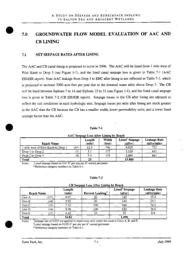
The AAC and CB canal lining is projected to occur in 2006. The AAC will be lined from 1 mile west of
Pilot Knob to Drop 3 (see Figure 1 - I ) , and the lined canal seepage loss is given in Table 7-1 (AAC
EISEIR report). Note AAC leakage from Drop 3 to EHC after lining is not reflected in Table 7-1, which
is projected to increase 2000 acre-feet per year due to the lowered water table above Drop 3. The CB
will be lined between Siphons 7 to 14 and Siphons 15 to 31 (see Figure 1-I) , and the lined canal seepage
loss is given in Table 7-2 (CB EISEIR report). Seepage losses in the CB after lining are adjusted to
reflect the soil conditions in each hydrologic unit. Seepage losses per mile after lining are much greater
in the AAC than the CB because the CB has a smaller width; lower permeability soils; and a lower lined
seepage factor than the AAC.
Table 7-1
[ Total 23 15,800 1 Notes: ' ~ i n e d seepage based on 0.07 ft3 per day per ft2 wetted perimeter
* Reference category numbers on Table 6- 1.
AAC Seepage Loss After Lining by Reach
Table 7-2
Reach Name 1 mile west of Pilot Knob to Drop 1 (6*) Drop 1 to Drop 2 (7) Drop 2 to Drop 3 (8)
CB Seepage Loss After Lining by Reach Length I ~ i n e d ~ Seepage I Leakage Rate I
Tetra Tech, Inc.
Leakage Rate (af7ydmile)
722 65 1 64 1
Length (mile) 12.5 5.1 5.4
Reach Name Unit A (13*)
Unit B (14)
Unit C (1 5 ) Unit D (16) Unit E ( 1 7) Total
July 1999
Width (feet) 196 177 174
Notes: 'seepage rate of 0.035 not applied to impervious soils under the canal in Units A, B, and E. 2 ~ i n e d seepage based on 0.035 ft3 per day per ft2 wetted perimeter * Reference category numbers on Table 6- 1 .
(mile) 9.07 5.92
. 7.32 8.09 4.42 34.82
~ i n e d l Seepage (affyr) 9.020 3,320 3,460
Percent ~ e a k i n ~ ' 20 30 1 00 1 00 10
(af/y r) 140 140 5 60 620 30
1,490
(aflyrlmile) 15.4 23.7 76.5 76.6 6.8

A STUDY O N S E E P A G E A N D S U B S U R F A C E I N F L O W S T O SALTON S E A A N D A D J A C E N T W E T L A N D S
7.2 PREDICTED POSTLINING GROUNDWATER LEVELS
The groundwater model is used to predict the changes in groundwater levels and aquifer flow rates that
result from the AAC and CB lining projects. The newly lined canals are simulated to begin operation in
2006.
The groundwater model presented in Section 6 simulated the steady-state condition prior to the lining of
the first 49 miles of the CB and transient conditions from 1980 through 2006 after the first 49 miles of
the CB were lined. For the model predictions of the AAC and CB lining projects, nearly all model
parameters were maintained at the same values used in the steady-state and transient calibration. The
only exceptions are that the iined canal leakance parameters were modified to reproduce the leakage rates
given in Tables 7-1 and 7-2; the model boundary heads were modified to account for future changes in
regional groundwater conditions (see Section 7.2.1); and wetland acreage and the amount of water
applied to wetlands was modified according to the mitigation measures defined in the AAC and CB
EISEIR report (see Section 7.2.3). Note that the alignment of the new lined canals was assumed to be
close enough to the original alignment, relative to the one-half mile model grid block size, to represent
the newly lined canals with the same locations used in model calibration.
7.2.1 Future Boundary Conditions
Future boundary conditions for the model are not known with certainty. As discussed in Section 3, there
are no long-term trends apparent in the regional groundwater conditions. Groundwater conditions in
Mexicali Valley are stable in the long-term with short-term fluctuations due to pumping in Mexicali and
excess Colorado River flows. This long-term trend is anticipated for the period from 1998 to 2006, and
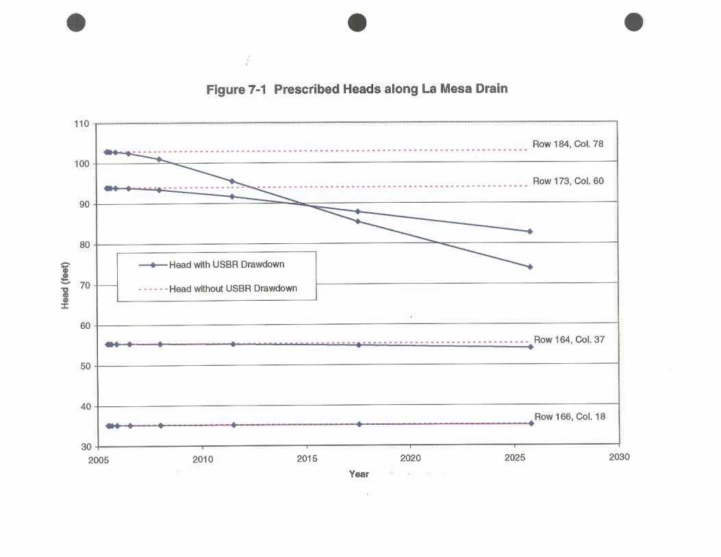
was projected into the future as illustrated in Figure 7-1. For the period from 2006 through 2025,
regional water levels may also exhibit a long-term decline in the northern Mexicali Valley due to the
lining of the AAC.
The USBR East Mesa Groundwater Model (Bureau of Reclamation 1984, 1987) was used to estimate the
declining water levels in the northern Mexicali Valley due to the lining of the AAC. The USBR model is
regional in scale covering the East Mesa, Mexicali Valley, and portions of central Imperial Valley as
depicted in Figure 6-1. This model has previously been calibrated to the rise in East Mesa and northern
Tetra Tech, Inc. 7 - 2 July 1999

A S T U D Y O N S E E P A G E A N D SUBSURFACE INFLOWS T O SAL'TON S E A A N D ADJACENT W E T L A N D S
e Mexicali Valley water levels from 1939 to 1972 due to the seepage from the AAC and the CB (Bureau of
Reclamation 1984).
The USBR model was used to account for the head response at the Seepage Study model/specified-head
boundaries due to lining the AAC from one mile west of Pilot Knob to Drop 3 (the section of the CB to
be lined is outside the boundary of the USBR model). The southern boundary of the Seepage Study
model coincides with the La Mesa Drain and is defined as a specified head boundary. This boundary is
relatively close to the AAC, so the head response from lining the AAC will affect the specified head
values. The USBR model was used for this purpose because it covers a larger area than the Seepage
Study model.
Durlng the time period of 2006 through 2026, specified heads for the Seepage Study model were
calculated by subtracting "drawdown" predicted by the USBR model from the average heads for 1979
through 1993 which were prescribed at the CHD boundary in the last stress period of transient simulation
( 1 998-2006). Thus the USBR modeled head response was used as a correction to the average regional
head. This correction was calculated and applied in each stress period for the predictive simulation (the
stress periods are shown in Table 6- 5). Corrected and uncorrected heads are shown at representative
CHD cells on Figure 7-1.
Several modifications were made to the USBR model for purposes of its application to the Seepage
Study. A summary of the modifications is presented below:
1 . Assigned the AAC recharge factor to be 0; used injection wells instead to simulate seepage
from the AAC. The injection rates were defined based on the Seepage Study's observed
flow rates for the AAC east of Drop 3.
2. Increased fault permeabilities in layer 1 by a factor of 100, to agree with the Seepage Study's
interpretation that the fault permeabilities decrease with depth.
3. Assigned storage coefficients to be 0.3 in layer 1; 1 . 6 ~ 1 0 ' ~ in layer 2; lxlo-' in layer 3, based
on calibrated Seepage Study model values.
4. Changed the cell width to 15,594.0 ft (4.753 km), and rotated the grid 5.58 degrees counter
clockwise, to match data contained in Plate 5 of the October 1987 USBR model report. The
Tetra Tech, Inc. 7-5 July I999
A S T U D Y O N SEEPAGE A N D S U B S U R F A C E INFLOWS T O S A L T O N S E A A N D A D J A C E N T W E T L A N D S
model origin (lower left comer) is at 2,219,481.75 feet Easting and -105,370.75 feet
Northing (California State Plane 1927).
5. Installed a subroutine to output a MODFLOW-style unformatted head file.
6. Performed minor modifications to input and output file formats.
7. Provided an independent FORTRAN program to transfer USBR modeled drawdowns to
Seepage Study model CHD cells.
These modifications were designed to make the USBR model compatible and internally consistent with
the Seepage Study MODFLOW model. For this study, the USBR model was used to simulate the
following two stress periods:
Continued seepage from the AAC and northern CB during the period from 2000 to 2006; and
The decline in water levels during the period 2006 to 2025 due to the AAC lining.
The Lower Colorado Water Supply Project calls for pumping up to 10,000 acre-feet per year of
groundwater from wells located near the Interstate 8 rest stop in the Sand Hills area. The water is for
exchange with the City of Needles and various other parties and pumping may begin some time in the
next several years. Pumping from this well was not included in this analysis in order to define impacts
solely attributed to the canal lining projects without interference from the effects of Lower Colorado
Water Supply Project.
7.2.2 Transient Simulation from 2006 through 2026 Without Mitigation
The SSA seepage study model predictions using the modified canal seepage rates and boundary
conditions assumed for lining the AAC and CB (i.e., without model changes reflecting the project
mitigation measures) are given for the period from 2006 to 2026 in Tables 7-3 and 7-4 and Figures 7-2
through 7-5. Figure 7-2 shows predicted evapotranspiration rates at the AAC Drop 3/Drop 4 wetlands
complex for the period from 2006 to 2026. Evapotranspiration rates at the AAC Drop 3/Drop 4 wetlands
complex drop roughly 22 percent to 4,139 acre-feet per year by 2026 without mitigation. Figure 7-3
Tetra Tech, Inc. 7-6 J& I999

A S T U D Y O N S E E P A G E A N D S U B S U R F A C E I N F L O W S T O S A L T O N S E A A N D A D J A C E N T W E T L A N D S
Table 7-3
Observed and Calibrated Model 2026 Water Balance
accuracy. Observed value is reduced to account for lining the AAC reach between Drop 2 and Drop 3. "Greater than" sign signifies that seepage west of Dro 3 IS expected to increase after lining the AAC. Less than" sign signifies that ~ ~ e d r a i n seepage is expected to decrease after lining the AAC. "Greater than" sign signifies that EHC canal seepage is expected to increase after lining the AAC. "Less than" sign sjgnjfies that discharge to the Salton Sea from the east shore is expected to decrease after lining the second 37 miles of the CB. Evapotranspiration is expected to decrease after lining the AAC and second 37 miles of the CB. Evapotranspiration along the first 49 miles of the CB is expected to be near zero after lining the first 49 miles, but
ublished estimates are not available. based on sum of mountain front recharge plus rising geothermal water. minus discharge as Salt Creek baseflow (Table 3-3). "Greater than" s i p signifies that available data are insufficient to estimate the applicable rate of rising eothermal water.
kising geothermal water is expected to exist east of the first 49 miles of the CB, but published estimates are not available.
"' 2026 underflow is expected to be greater than the published value for the 1960s. because the first 49 miles of the CB was lined after 1979 and the AAC and second 37 miles of the CB were lined after 2005.
I ' 2026 underflow is expected to be less than the published value for 1980 to 1993, because the AAC and second 37 miles of the CB were lined after 2005.
Tetra Tech, Inc. 7-7 July 1999

A S T U D Y O N S E E P A G E A N D S U B S U R F A C E I N F L O W S T O S A L T O N S E A A N D A D J A C E N T W E T L A N D S
shows predicted evapotranspiration rates at the CB wetlands for the period from 2006 to 2026.
Evapotranspiration rates at the CB wetlands drop 35 percent to 24,643 acre-feet per year by 2026 without
mitigation.
Table 7-4
Salton Sea Observed and Modeled 2026 Water Budget
Figures 7-2 and 7-3 also show the predicted long-term steady-state seepage rates. The steady-state
seepage rates for the AAC wetlands drop 56 percent to 2,333 acre-feet per year, and steady-state seepage
rates for the CB wetlands drop 63 percent to 14,218 acre-feet per year. The transient and steady-state
seepage rates shown in Figures 7-2 and 7-3 define upper and lower limits for the actual seepage rate in
2026. The steady-state seepage rate could be reached before 2026, if the actual specific yield value is
significantly less than the modeled value of 0.25. Smaller values of specific yield are possible given the
uncertainty associated with the available data. The specific yield value has no effect on the computed
steady-state seepage rate; it only affects the time when the steady-state rate will be reached (smaller
values of specific yield cause steady-state conditions to occur sooner). Thus, the percentage drop in
seepage rates by 2026 ranges from 22 to 56 percent for the AAC and from 35 to 63 percent for the CB.
For comparison, the Draft EIR mitigates for a 75 percent drop in the CB wetlands within 10 years.
Inflow from Groundwater Discharge Surface Inflow Precipitation Evaporation
Stage
Evaporation Rate
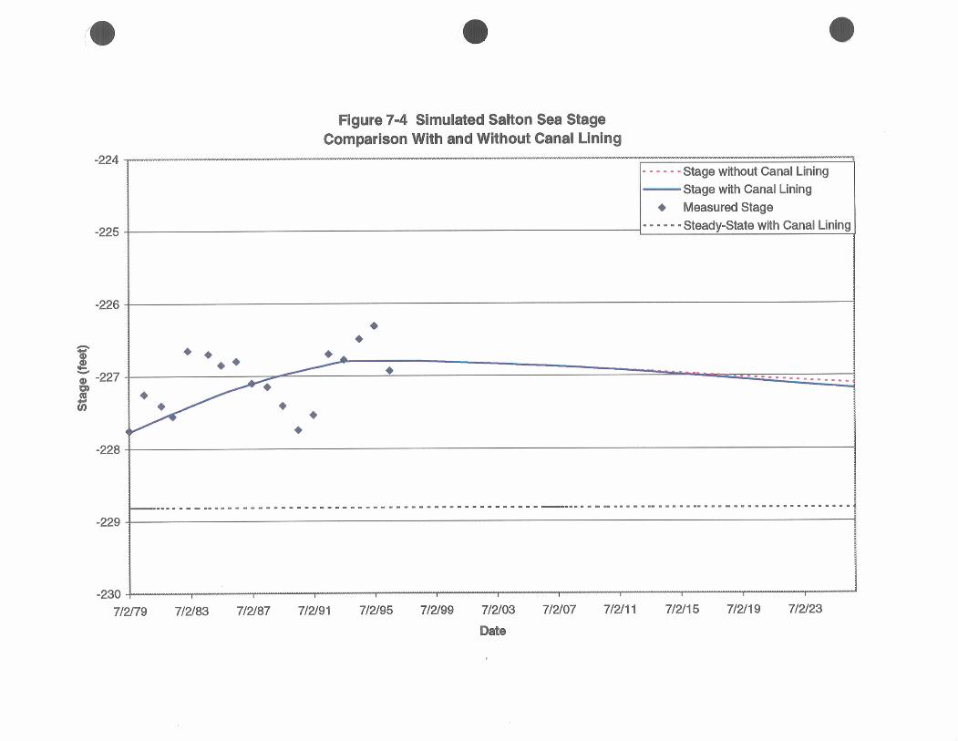
Figure 7-4 shows predicted stage of the Salton Sea for the period 2006 through 2026. The Salton Sea
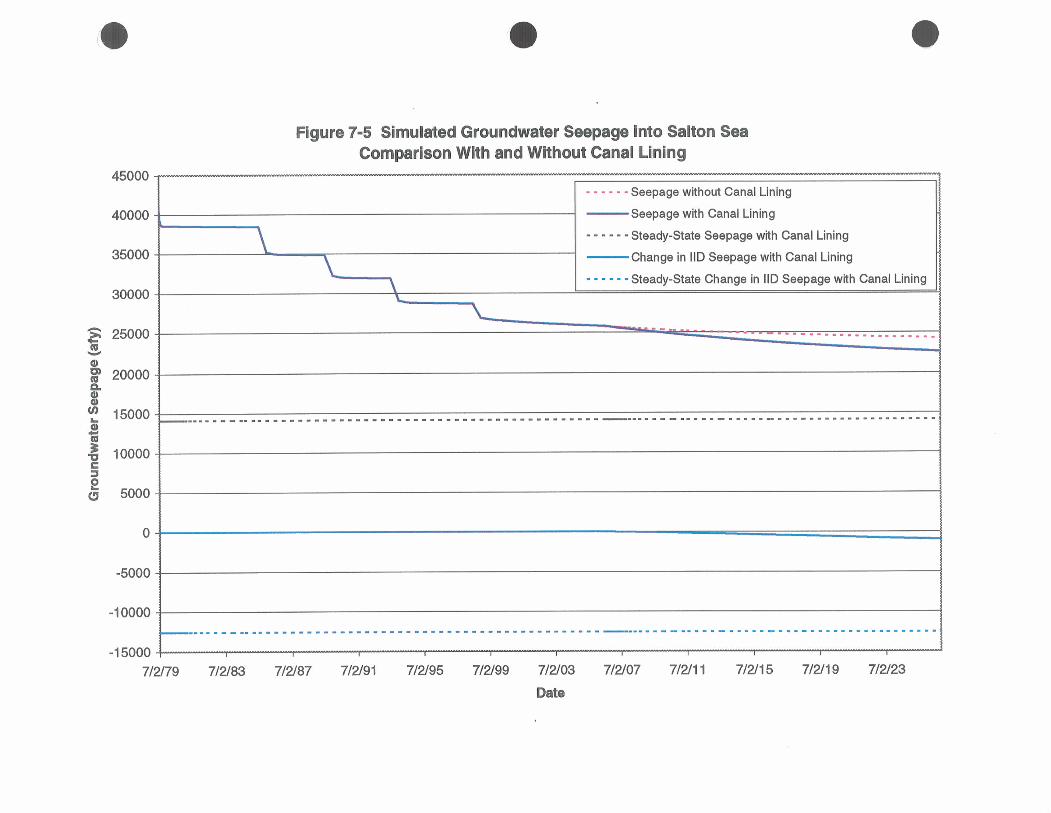
stage may drop by a range of less than 1 inch to 1.7 feet by the end of the simulation. Figure 7-5 shows
predicted groundwater seepage rate to the Salton Sea for the period 2006 through 2026. The groundwater
Tetra Tech, Inc. 7-8 July 1999
Notes: ' Model output values are shown in bold type. Values are rounded only to the nearest aflyr for convenience in verifying against model output files. Rounding to the nearest 1,000 aflyr is appropriate to indicate the degree of predictive accuracy. ' aflyr = acre-feet per year
'observed Surface Inflow after 1993 was adjusted to match a steady-state Salton Sea budget calculated for 1993 conditions. This assumes future surface inflow will be similar to the 1993 value.
'observed evaporation for 2026 is expected to be less than the 1993 value, because the Salton Sea stage will fall after the AAC and CB canals are lined. amsl = above mean sea level
Observed Value 1 3 3 17 aflyr2
1,368,306 aflyr 3 1,500 aflyr
(< 1,428,060) aflyr
(> 226.78)' ft. ams15
5.78 Wyr
Modeled value' 22,605 aflyr
1,368,306 aflyr 31,500 aflyr
(1,426,442) aflyr
(227.18) ft. amsl
5.78 Wyr
Timing 2006 to ?
1994 to ? 1959 to 1962
2026
2026
1948 to 1962
Reference CVWD
calculated3 USGS 486-C Univ. of Redlands Bathimetry CRBC (Tostrud, 1997) USGS 486-C


Wgure 7-3 Evapotranspiration Rate Along Coachella Branch
- EVT with Canal Lining ---- EVT without Canal Lining - ....-, Steadystate EVT with Canal Lining
7/7/05 711 2/05
Date
0009 1-
0000 L-
0009-
0
0009
0000 1
0009 1
0000z
0009Z
ooOo€
ooolie
OOOOP
0009P

A S T U D Y O N S E E P A G E A N D S U B S U R F A C E I N F L O W S T O S A L T O N S E A A N D A D J A C E N T W E T L A N D S
a seepage rate into the Salton Sea may decline by a range of 1,715 acre-feet per year to 10,208 acre-feet per
year by the end of the simulation.
Net discharge into the East Highline Canal southern segment ceases by 2026. Recharge due to increased
seepage along the entire East Highline Canal may increase by a range of 746 acre-feet per year to
11,521 acre-feet per year by 2026. Discharge into the New and Alamo Rivers may decrease by a range of
9 acre-feet per year to 114 acre-feet per year by 2026, which is an insignificant change. Discharge into
the IID irrigation system may decrease by a range of 971 acre-feet per year to 12,542 acre-feet per year in
2026, which is a net change of 4 to 58 percent.
7.2.3 Transient Simulation from 2006 through 2026 with Mitigation
Mitigation measures have been proposed for both the AAC and CB lining projects to permit their
implementation with no significant loss of environmental resources, where the primary concerns are the
loss of seepage-induced wetlands along the canals and the reduction in canal fish population. The
mitigation measures proposed for each project were evaluated to quantify the amount of water that may
be lost to the Salton Sea and adjacent wetlands due to the implementation of the mitigation measures as
@ pan of the AAC and CB canal lining projects.
7.2.3.1 Mitigation Measures
AAC Mitigation Measures. The following mjtigation measures were defined for the AAC lining project
(Bureau of Reclamation 1994):
Enlarge the wetlands complex between Drops 3 and 4 by adding 43 acres of mesquite and
cottonwood/willow and 1 acre of marsh to compensate for the loss of 100 acres of isolated
wetlands and 24 acres of canal vegetation above Drop 3;
Acre-for-acre replacement of 587 acres of desert scmb habitat and 916 acres of sand dune
habitat which would be lost due to the project;
Funding of $100,000 to improve backwater along the lower Colorado River to ensure the
AAC lining project does not cause an adverse change to wetlands along the Colorado River;
and
Tetra Tech, Inc. 7-17 July 1999

A S T U D Y O N S E E P A G E A N D S U B S U R F A C E I N F L O W S T O S A L T O N S E A A N D A D J A C E N T W E T L A N D S
Installation of artificial reefs to maintain recreational fishery habitat.
There are no impacts on the groundwater system along the AAC from the last three mitigation measures.
For the first mitigation measure, there could be an impact on the groundwater system along the AAC due
to the water supply requirements for the 44 acres of wetlands added between Drops 3 and 4. The AAC
EISEIR project (Bureau of Reclamation 1994) does not specify a water supply requirement nor a water
source for the 44 acres of wetlands added between Drops 3 and 4. However, it is probable that the added
wetlands would be sustained naturally by the shallow groundwater between Drops 3 and 4, and pumping
groundwater or diverting water from the nearby canal will not be necessary. If that is the case, the only
impact of the mitigation measures on the aquifer would be a modest increase in evapotranspiration
between Drops 3 and 4.
Thus, the only impact of the proposed mitigation increasing the Drop 31Drop 4 wetland complex acreage
from its current value of 1,422 acres to 1,466 acres is to increase total annual evapotranspiration from its
current value of 6,941 aflyr to 7,156 aftyr. For model predictions of post-lining conditions, the net effect
of the AAC mitigation measures is not simulated by the groundwater model because the model simulates
evapotranspiration from a deep water table whereas the mitigation measures call, for surface application
of water. This surface application will be consumed by evapotranspiration before reaching the water
table, and therefore, this shallow evapotranspiration is additive to any evapotranspiration predicted by the
model. This also assumes that the shallow watering of wetlands undertaken for project mitigation will
not at all effect the model predictions of evapotranspiration from a deep water table.
CB Mitigation Measures The following mitigation measures were defined for the CB lining project
(Bureau of Reclamation, 1993):
Establish an additional 1,276 acres of mesquite, cottonwood/willow, and California palm in
the Salt Creek Area of Critical Environmental Concern (ACEC);
Replacement of lost mature trees at a ratio of two trees for every tree destroyed;
Funding of $30,000 to improve backwater along the lower Colorado River to ensure the CB
lining project does not cause an adverse change to wetlands along the Colorado River; and
Tetra Tech, Inc. 7-18 July 1999

A STUDY O N S E E P A G E A N D SUBSURFACE INFLOWS T O S A L T O N S E A A N D A D J A C E N T W E T L A N D S
Installation of artificial reefs to maintain recreational fishery habitat.
There are no impacts on the groundwater system along the CB from the last three mitigation measures.
For the first mitigation measure, there could be an impact on the groundwater system along the CB due to
the water supply requirements for the 1,276 acres of wetlands added to the Salt Creek ACEC. The CB
EISIEIR project (Bureau of Reclamation 1993) specifies a water supply requirement of 7,125 acre-feet
per year for the ACEC, which includes a commitment to maintain baseflow in Salt Creek to protect the
desert pupfish. The mitigation water supply would be arranged so that runoff from the wetlands would
supply Salt Creek.
Water supply would be derived from existing wells and springs in the Dos Palmas area; new wells
developing up to 2,000 acre-feet per year of lower-quality artesian water near the canal; and diversions
from the canal. Maximizing the amount of water available from other sources, however, will minimize
the water diverted from the canal. The water supply requirements of the 1,276 acres of wetlands added at
Salt Creek ACEC also depends upon the response of the existing ACEC wetlands to the canal lining.
There are currently 3,014 acres of wetlands in the ACEC (mostly salt cedar) and 667 acres are projected
to remain after the CB lining without mitigation. Approximately 3,335 acre-feet per year of regional
groundwater will be required to support the remaining 667 acres of wetlands.
The impact of the proposed mitigation would be to increase ACEC wetland complex acreage from its
projected future value of 667 acres to 1,943 acres. Water requirements for mitigation will be supplied by
5,125 acre-feet per year of artesian discharge from existing wells/springs and 2,000 acre-feet per year
from new wells in the deeper aquifer, unless the capacity of these sources is inadequate in which case
canal water may be diverted.
For modeling purposes, the post-lining CB mitigation measures will be simulated by setting an overall
evapotranspiration target of 14,200 aflyr in the ACEC wetlands complex (to account for the removal of
salt cedar and mitigation with native vegetation). The 14,200 target includes the pumping rate from a
deep artesian well located near the canal between siphons 26 and 27 (490,600 feet Northing and
3,132,000 feet Easting or model row 20 and column 52). In the event that the shallow aquifer can sustain
14,200 aflyr of evapotranspiration, no water will be applied to the wetlands by pumping the deep well. In
the event that the shallow aquifer cannot sustain 14,200 aflyr of evapotranspiration, up to 2,000 acre-feet
per year of additional water will be pumped from the deep well. In the event that the shallow aquifer
Tetra Tech, Inc. 7-19 July 1999

A S T U D Y O N S E E P A G E A N D S U B S U R F A C E I N F L O W S T O S A L T O N S E A A N D A D J A C E N T W E T L A N D S
cannot sustain 12,200 aflyr of evapotranspiration, the full 2,000 acre-feet per year will be pumped from
the deep well and any additional water required to sustain 12,200 aflyr of evapotranspiration will be
diverted from the canal for surface application to maintain the prescribed evapotranspiration rate required
to support the 2,695 acres of wetlands.
7.2.3.2 Simulation Results
The SSA seepage study model predictions without mitigation measures are given in Section 7.1. The
SSA seepage study model predictions with mitigation measures are adjusted as discussed in
Section 7.2.1. All mitigation measures requiring surface application of water to wetlands are addressed
outside of the numerical model framework; the only mitigation measure which would require adjusting
the model is the pumping of 2,000 acre-feet per year near the Salt Creek area. However, since the steady-
state wetlands evapotranspiration rate is above the target level of 14,200 acre-feet per year, this
mitigation measure would not be required based on the mode1 used for this study. Thus, there are no
model revisions needed to address the mitigation measures, and the model results given in Section 7.2.2
can be used to define the post-mitigation seepage conditions.
After mitigation, the evapotranspiration rates at the AAC Drop 3/Drop 4 wetlands are maintained at
5,546 acre-feet per year through 2026. This will require mitigation measures that apply 220 acre-feet per
year of water to develop new wetlands in the Drop 3/Drop 4 complex, and 1,187 to 2,993 acre-feet per
year of water to existing wetlands in the Drop 3/Drop 4 complex to compensate for lower
evapotranspiration rates from the deeper water table beneath the Drop 3JDrop 4 complex.
Evapotranspiration rates at the CB wetlands are predicted to range from 14,218 to 24,643 acre-feet per
year by 2026 with or without mitigation, as mitigation measures did not raise evapotranspiration rates in
this area during this time period. The mitigation measures do not impact groundwater seepage rate into
the Salton Sea; specifically, there is a decline ranging from 1,715 to 10,208 acre-feet per year by the end
of the simulation with or without mitigation. Discharges into the East Highline Canal, the New and
Alamo Rivers, and the I D irrigation drains are not effected by the project mitigation measures. Net
discharge into the East Highline Canal southern segment ceases by 2026. Recharge due to increased
seepage along the entire East Highline Canal may increase by a range of 746 acre-feet per year to
11,521 acre-feet per year by 2026. Discharge into the New and Alamo Rivers may decrease by a range of
9 acre-feet per year to 114 acre-feet per year by 2026, which is an insignificant change. Discharge into
the I D irrigation system may decrease by a range of 971 acre-feet per year to 12,542 acre-feet per year in
2026, which is a net change of 4 to 58 percent.
Tetra Tech, Inc. 7-20 July 1999