grounding of multi cable transits for on-shore use
TRANSCRIPT
1
Grounding of Multi-Cable Transits
Mathieu Melenhorst
Alewijnse Marine Nijmegen
P.O. Box 6973
6541 CX Nijmegen, the Netherlands
Mark van Helvoort
Philips Healthcare
MRI Development
Best, the Netherlands
Abstract— Multi-Cable Transits are for transferring piping
and cabling between sealed compartments.
Keywords—EMC, shielding, cabling.
I. INTRODUCTION
Multi-Cable Transits (MCT’s) are used for transferring cabling and piping between two sealed compartments in order to prevent the spread of fire, water, gas and chemicals. More recently E-MCT’s have been introduced which offer additional protection against electromagnetic pulse and interference. Traditionally these are applied in naval and offshore applications [1][2].
In this paper we study the application of E-MCT’s in on-shore building cable entry points [4]. In these situations there is no full metal bulkhead available for mounting and grounding the frame of the E-MCT. We show that proper grounding of the frame is of main importance in addition to the grounding of the individual modules.
Corrosion prevention, especially in on-shore applications where dissimilar metals might be joined, will not be covered. However it requires attention.
The organization of this paper is as follows. First we provide a description of E-MCT’s in Section II. Subsequently, we discuss the coupling paths in Section III. We discuss lightning protection as a use case in Section IV. The measurement setup is described in Section V and the results are shown in Section VI. Conclusions will be presented in Section VII.
II. BACKGROUND
MCT’s are basically rubber blocks, modules, which form a gas- and watertight barrier between two compartments. Special EMC versions, E-MCT’s, exist that also provide electromagnetic attenuation by conductively contacting the cable shields to the metallic enclosing frame, hence providing an alternative path for the shield currents to flow.
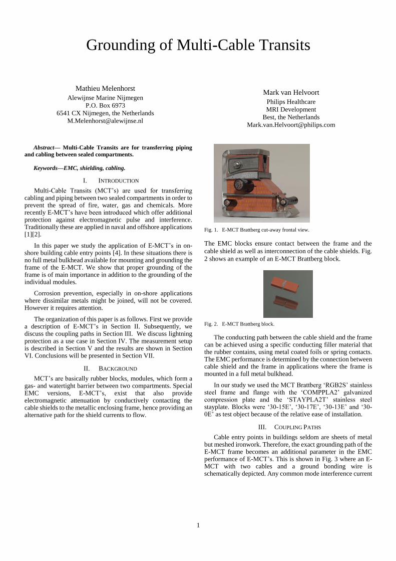
Fig. 1. E-MCT Brattberg cut-away frontal view.
The EMC blocks ensure contact between the frame and the
cable shield as well as interconnection of the cable shields. Fig.
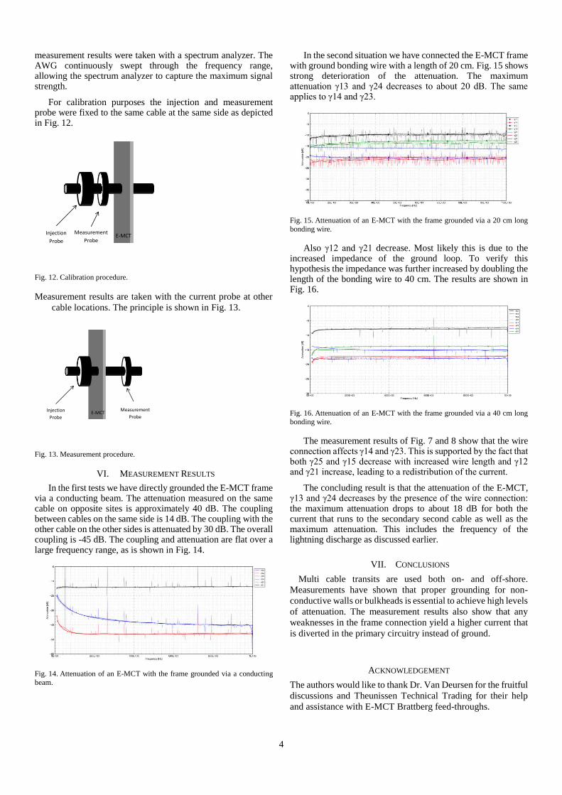
2 shows an example of an E-MCT Brattberg block.
Fig. 2. E-MCT Brattberg block.
The conducting path between the cable shield and the frame can be achieved using a specific conducting filler material that the rubber contains, using metal coated foils or spring contacts. The EMC performance is determined by the connection between cable shield and the frame in applications where the frame is mounted in a full metal bulkhead.
In our study we used the MCT Brattberg ‘RGB2S’ stainless steel frame and flange with the ‘COMPPLA2’ galvanized compression plate and the ‘STAYPLA2T’ stainless steel stayplate. Blocks were ‘30-15E’, ‘30-17E’, ‘30-13E’ and ‘30-0E’ as test object because of the relative ease of installation.
III. COUPLING PATHS
Cable entry points in buildings seldom are sheets of metal but meshed ironwork. Therefore, the exact grounding path of the E-MCT frame becomes an additional parameter in the EMC performance of E-MCT’s. This is shown in Fig. 3 where an E-MCT with two cables and a ground bonding wire is schematically depicted. Any common mode interference current

2
that flows over cables 1 and 2 will flow back to the ground plane via the ground bonding wire. The common mode currents on the primary and secondary site are mutually coupled as designated by 𝑀𝑝𝑠 [5].
Fig. 3. Mutual coupling of loops formed by the ground bonding wire.
All current paths between currents on the primary side to the
secondary side are depicted in Fig. 4.
Fig. 4. Current paths in an E-MCT.
The overall current distribution in the setup is expressed by the following matrix:
In which ‘R’ represents the resistance of the wire connection. In case only cable 1 would be fed through the E-MCT, the secondary current can be calculated using:
𝐼𝑐 =𝑗𝜔𝑀𝑎𝑐 + 𝑅
𝑍𝑐∙ 𝐼𝑎
Which reduces to 𝐼𝑐 =𝑅
𝑍𝑐∙ 𝐼𝑎 for DC.
With: 𝑍𝑐 = 𝑅𝑐,1 + 𝑅𝑐,2 + 𝑅
The resistances ‘Rc,1’ and ‘Rc,2’ represent the conductor resistances. It becomes clear from these expressions that the
resistance ‘R’ between the mounting frame and the ground connection plays a dominant role in coupling between the circuits when 𝑅 ≫ 𝑅𝑐,1 + 𝑅𝑐,2
Lightning discharges will likely cause an excitation of cable bundles that are routed through the E-MCT. The lightning discharge current will therefore represent a common-mode current: 𝐼𝑐𝑚,𝑝 = 𝐼1 + 𝐼2 and 𝐼𝑐𝑚,𝑠 = 𝐼3 + 𝐼4. The frame-to-
ground resistance remains 𝑅. The secondary induced current will now be expressed by:
𝐼𝑐𝑚,𝑠 =(𝑗𝜔𝑀𝑝𝑠 + 𝑅)
𝑍𝑐𝑚,𝑠∙ 𝐼𝑐𝑚,𝑝
This expression shows that the resistance is of major importance as is the coupling between the primary and the secondary cable loops which is determined by the physical layout of the cabling. This in turn also includes the gound bond wire that is represented by its resistance, R.
IV. LIGHTNING USE CASE
MCTs are used on-shore where cables enter buildings in the
soil. The main objective of the MCTs is to provide a watertight
barrier between the outside world and the building’s innards.
Large installations that are stretched over large areas like
chemical plants, oil refineries, infrastructural projects and
others are subject to direct or indirect lightning strokes. The
economic and social impact can be tremendous if service is lost.
Lightning protection is one of the important on-shore
applications for E-MCTs as partial lightning discharge currents
travel via the braids of shielded cables. Lightning currents are
then diverted at the boundary of the building as Fig. 5 shows.
Fig. 5. Building cable entry.
The lightning current is characterized by the 10/350 µs pulse.
The rise time of the pulse coincides with a sine wave for which
its frequency can be calculated via:
𝑓 =sin−1(0.9)
2𝜋𝑡10%−90%[Hz]
This yields f = 18 kHz which corresponds to [3]. Both
transient and sine wave are shown in Fig. 6. The frame to
building bonding is important since lightning is a common-
mode phenomenon meaning that connection number 5 of Fig. 4
acts like a pigtail. In addition, proper corrosion protection and
inspection is required to avoid non-linearity’s that might occur.
1
2
Primary Secondary
E-M
CT
3
4
5
−1𝑗𝜔𝑀𝑏𝑎 + 𝑅
𝑍𝑎
𝑗𝜔𝑀𝑐𝑎 + 𝑅
𝑍𝑎
𝑗𝜔𝑀𝑑𝑎 + 𝑅
𝑍𝑎𝑗𝜔𝑀𝑎𝑏 + 𝑅
𝑍𝑏−1
𝑗𝜔𝑀𝑐𝑏 + 𝑅
𝑍𝑏
𝑗𝜔𝑀𝑑𝑏 + 𝑅
𝑍𝑏𝑗𝜔𝑀𝑎𝑐 + 𝑅
𝑍𝑐
𝑗𝜔𝑀𝑏𝑐 + 𝑅
𝑍𝑐−1
𝑗𝜔𝑀𝑑𝑐 + 𝑅
𝑍𝑐𝑗𝜔𝑀𝑎𝑑 + 𝑅
𝑍𝑑
𝑗𝜔𝑀𝑏𝑑 + 𝑅
𝑍𝑑
𝑗𝜔𝑀𝑐𝑑 + 𝑅
𝑍𝑑−1
𝐼𝑎
𝐼𝑏
𝐼𝑐
𝐼𝑑
= 0
Mps

3
Fig. 6. Lightning pulse and sine wave front.
The attenuation of the E-MCT for lightning phenomena can thus be evaluated using a current with f = 18 kHz.
A practical example of a retrofit is shown in Fig. 7.
Fig. 7. Roxtec feedthrough, modified to EMC version
The effect of introducing any such pigtail for diverting
lightning currents is measured. Fig. 8 shows the achieved
attenuation with the E-MCT frame grounded using a
conducting beam.
The attenuation is expressed as 𝛾𝑚𝑛 = 𝐼𝑚 − 𝐼𝑛[𝑑𝐵]
Fig. 8. Attenuation of the E-MCT when grounded via a conducting beam.
Fig. 7 shows the situation where an existing Roxtec feed-
through is upgraded with EMC blocks in order to divert
lightning currents that travel on the cable’s shields. The effect
of grounding the frame with a wire (pigtail) is shown in Fig. 9.
Fig. 9. Attenuation of the E-MCT, grounded via 20 cm wire.
The wire length in this case is 20 cm. It has little impact on
the attenuation of the 18 kHz current diversion. However, an
extensive length of the pigtail will deteriorate the attenuation.
V. MEASUREMENT SETUP
The measurement setup is shown in Fig. 10. The cable or tube
is terminated at both ends to the solid ground plane. Current is
injected at the primary side where it is attenuated by the E-MCT
and the conducting beam or an isolating beam with a wire. The
wire length is either 20 cm or 40 cm.
Fig. 10. Measurement setup.
The E-MCT is either mounted directly in contact with the
ground plane or via a ground bonding wire. We fed a standard
braided cable (YMvKAS) through the E-MCT and a copper
tube as reference conductor.
Fig. 11. Measurement setup.
The full attenuation matrix has been determined by means of the bulk current injection probe method, similar to the setup reported in [2]. The injection probe was mounted on the primary site, alternatively around the YMVkAS cable and the copper tube. Current on all cables were measured with the measurement probe on both primary and secondary side. An arbitrary waveform generator with an amplifier acted as source while the
Primary Secondary
Termination block
Termination block
Beam
E-MCT
Cable Cable
Wire
(if applicable)
4
measurement results were taken with a spectrum analyzer. The AWG continuously swept through the frequency range, allowing the spectrum analyzer to capture the maximum signal strength.
For calibration purposes the injection and measurement probe were fixed to the same cable at the same side as depicted in Fig. 12.
Fig. 12. Calibration procedure.
Measurement results are taken with the current probe at other
cable locations. The principle is shown in Fig. 13.
Fig. 13. Measurement procedure.
VI. MEASUREMENT RESULTS
In the first tests we have directly grounded the E-MCT frame via a conducting beam. The attenuation measured on the same cable on opposite sites is approximately 40 dB. The coupling between cables on the same side is 14 dB. The coupling with the other cable on the other sides is attenuated by 30 dB. The overall coupling is -45 dB. The coupling and attenuation are flat over a large frequency range, as is shown in Fig. 14.
Fig. 14. Attenuation of an E-MCT with the frame grounded via a conducting
beam.
In the second situation we have connected the E-MCT frame with ground bonding wire with a length of 20 cm. Fig. 15 shows strong deterioration of the attenuation. The maximum attenuation γ13 and γ24 decreases to about 20 dB. The same applies to γ14 and γ23.
Fig. 15. Attenuation of an E-MCT with the frame grounded via a 20 cm long
bonding wire.
Also γ12 and γ21 decrease. Most likely this is due to the increased impedance of the ground loop. To verify this hypothesis the impedance was further increased by doubling the length of the bonding wire to 40 cm. The results are shown in Fig. 16.
Fig. 16. Attenuation of an E-MCT with the frame grounded via a 40 cm long
bonding wire.
The measurement results of Fig. 7 and 8 show that the wire connection affects γ14 and γ23. This is supported by the fact that both γ25 and γ15 decrease with increased wire length and γ12 and γ21 increase, leading to a redistribution of the current.
The concluding result is that the attenuation of the E-MCT, γ13 and γ24 decreases by the presence of the wire connection: the maximum attenuation drops to about 18 dB for both the current that runs to the secondary second cable as well as the maximum attenuation. This includes the frequency of the lightning discharge as discussed earlier.
VII. CONCLUSIONS
Multi cable transits are used both on- and off-shore.
Measurements have shown that proper grounding for non-
conductive walls or bulkheads is essential to achieve high levels
of attenuation. The measurement results also show that any
weaknesses in the frame connection yield a higher current that
is diverted in the primary circuitry instead of ground.
ACKNOWLEDGEMENT
The authors would like to thank Dr. Van Deursen for the fruitful
discussions and Theunissen Technical Trading for their help
and assistance with E-MCT Brattberg feed-throughs.
Measurement
Probe
Injection
Probe E-MCT
Measurement
Probe
Injection
Probe E-MCT

5
REFERENCES
[1] IEEE STD45-2002, Recommended Practice for Electric Installations on Shipboard
[2] J.G. Bergsma, B.J.A.M. van Leersum, M.J.E. Melenhorst, F.B.J. Leferink, Effectiveness of Cable Transits, and how it is easily void, EMC Europe 2013, p. 16-19
[3] G. Bargboer, p. 8, 21, Measurements and modeling of EMC applied to cabling and wiring, PhD Thesis, Eindhoven University of Technology, May 2011.
[4] International Electrotechnical Commission (IEC )
[5] M.J.A.M. van Helvoort and M.J.E. Melenhorst, EMC van Installaties (in Dutch).