ground-water data-collection protocols … · one of the greatest challenges faced by water- ... c...
TRANSCRIPT
GROUND-WATER DATA-COLLECTION PROTOCOLS AND PROCEDURES
FOR THE NATIONAL WATER-QUALITY ASSESSMENT PROGRAM:
COLLECTION AND DOCUMENTATION OF WATER-QUALITY
SAMPLES AND RELATED DATA
____________________________________________________________________________________________________________________________________________________________________
U.S. GEOLOGICAL SURVEY
Open-File Report 95-399
NATIONAL WATER-QUALITY ASSESSMENT PROGRAM
National Water-Quality Assessment Study Unit

GROUND-WATER DATA-COLLECTION PROTOCOLS AND PROCEDURES
FOR THE NATIONAL WATER-QUALITY ASSESSMENT PROGRAM:
COLLECTION AND DOCUMENTATION OF WATER-QUALITY
SAMPLES AND RELATED DATA
By Michael T. Koterba, Franceska D. Wilde, and Wayne W. Lapham
______________________________________________________________
U.S. Geological Survey
Open-File Report 95-399
Reston, Virginia
1995

U.S. DEPARTMENT OF THE INTERIOR
BRUCE BABBITT, Secretary Seal
U.S. GEOLOGICAL SURVEY
Gordon P. Eaton, Director
Any use of trade, product, or firm names in this publication is for descriptive purposes onlyand does not imply endorsement by the U.S. Government.
_________________________________________________________________________
For additional information, write to: Copies of this report can be purchased from:
NAWQA - Mail Stop 413 U.S. Geological SurveyU.S. Geological Survey Earth Science Information Center12201 Sunrise Valley Drive Open-File Reports SectionReston, Virginia 22092 Box 25286, MS 517
Denver Federal CenterDenver, Colorado 80225
FOREWORD
The mission of the U.S. Geological Survey(USGS) is to assess the quantity and quality of theearth resources of the Nation and to provide informa-tion that will assist resource managers and policymak-ers at Federal, State, and local levels in making sounddecisions. Assessment of water-quality conditions andtrends is an important part of this overall mission.
One of the greatest challenges faced by water-resources scientists is acquiring reliable informationthat will guide the use and protection of the Nation'swater resources. That challenge is being addressed byFederal, State, interstate, and local water-resourceagencies and by many academic institutions. Theseorganizations are collecting water-quality data for ahost of purposes that include: compliance with permitsand water-supply standards; development of remedia-tion plans for specific contamination problems; opera-tional decisions on industrial, wastewater, or water-supply facilities; and research on factors that affectwater quality. An additional need for water-qualityinformation is to provide a basis on which regional-and national-level policy decisions can be based. Wisedecisions must be based on sound information. As asociety we need to know whether certain types ofwater-quality problems are isolated or ubiquitous,whether there are significant differences in conditionsamong regions, whether the conditions are changingover time, and why these conditions change fromplace to place and over time. The information can beused to help determine the efficacy of existing water-quality policies and to help analysts determine theneed for and likely consequences of new policies.
To address these needs, the U.S. Congress appropri-ated funds in 1986 for the USGS to begin a pilot pro-gram in seven project areas to develop and refine theNational Water-Quality Assessment (NAWQA) Pro-gram. In 1991, the USGS began full implementation ofthe program. The NAWQA Program builds upon anexisting base of water-quality studies of the USGS, aswell as those of other Federal, State, and local agencies.The objectives of the NAWQA Program are to:
- Describe current water-quality conditions for alarge part of the NationÕs freshwater streams,rivers, and aquifers.
- Describe how water quality is changing overtime.
- Improve understanding of the primary naturaland human factors that affect water-qualityconditions.
This information will help support the developmentand evaluation of management, regulatory, and moni-toring decisions by other Federal, State, and localagencies to protect, use, and enhance water resources.
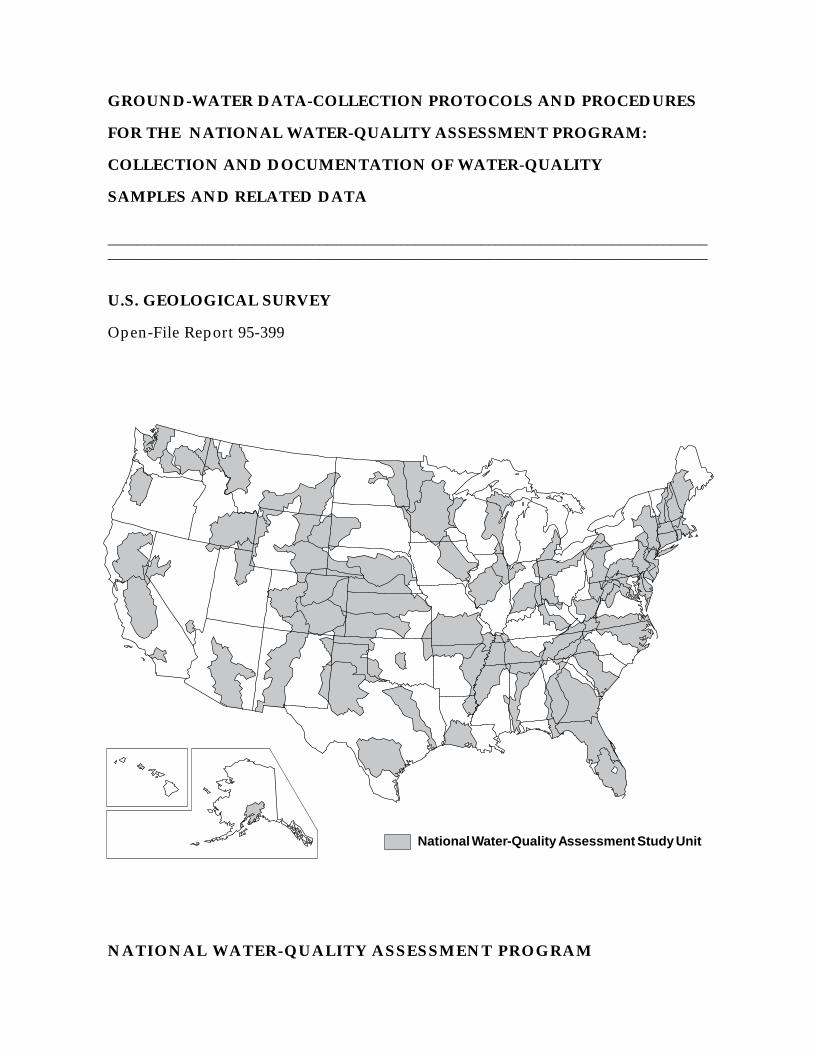
The goals of the NAWQA Program are beingachieved through ongoing and proposed investigationsof 60 of the Nation's most important river basins andaquifer systems, which are referred to as study units.These study units are distributed throughout theNation and cover a diversity of hydrogeologic settings.More than two-thirds of the Nation's freshwater useoccurs within the 60 study units and more than two-thirds of the people served by public water-supply sys-tems live within their boundaries.
National synthesis of data analysis, based onaggregation of comparable information obtained fromthe study units, is a major component of the program.This effort focuses on selected water-quality topicsusing nationally consistent information. Comparativestudies will explain differences and similarities inobserved water-quality conditions among study areasand will identify changes and trends and their causes.The first topics addressed by the national synthesis arepesticides, nutrients, volatile organic compounds, andaquatic biology. Discussions on these and other water-quality topics will be published in periodic summariesof the quality of the Nation's ground and surface wateras the information becomes available.
This report is an element of the comprehensivebody of information developed as part of the NAWQAProgram. The program depends heavily on the advice,cooperation, and information from many Federal,State, interstate, Tribal, and local agencies and thepublic. The assistance and suggestions of all aregreatly appreciated.
Robert M. HirschChief Hydrologist
(signed)

CONTENTS
Page
Foreword............................................................................................................................ iiiAbstract .............................................................................................................................. 1Introduction......................................................................................................................... 1
Background.................................................................................................................. 2Purpose and scope ....................................................................................................... 3Quality assurance and quality control ......................................................................... 3Acknowledgments ...................................................................................................... 4
Collection and documentation of water-quality samples and related data ......................... 5Data-quality requirements ........................................................................................... 5Plans and preparations................................................................................................. 8
Site visits.............................................................................................................. 9Selection and purchase of equipment and supplies ............................................. 9
Pump systems .............................................................................................. 17Field instruments ......................................................................................... 20Water-quality vehicles.................................................................................. 22Storage facilities ........................................................................................... 23Timing of purchases ..................................................................................... 23
Training................................................................................................................ 24Field evaluation.................................................................................................... 24Design of ground-water-quality sampling schedules........................................... 26Design of quality-control sampling and schedules ............................................. 30
Routine quality-control-samples: type, number, site selection, and timing . 33Example of routine quality-control design: a case study ............................. 39Topical quality-control samples .................................................................. 42
Sample coding and data management ................................................................. 42Final presampling plans and preparations ........................................................... 48
Field protocols and recommended procedures ........................................................... 51Equipment setup................................................................................................... 52Well purging, grab samples, and field measurements ........................................ 52
Acceptable deviations from standard purge protocols ................................ 56Purging with different flow rates ................................................................. 58Purging different types of wells ................................................................... 59Grab samples for titrations and volatile-sample preservation ..................... 61Final assessment of chemical stability ......................................................... 63
Sample collection and processing........................................................................ 63Field-team functions..................................................................................... 68Special considerations for selected sample types......................................... 68
Decontamination of field equipment ................................................................... 70Preparation of blank samples .............................................................................. 76Preparation of other routine quality-control samples and field extracts
of pesticide samples...................................................................................... 76Pesticide and volatile-organic-compound (VOC) spiked samples .............. 80Pesticide solid-phase extractions ................................................................. 80VOC trip-blank and trace-element standard reference samples ................... 82
Handling and shipping of samples....................................................................... 82References cited ................................................................................................................. 84Appendix. Examples of field forms for the collection of ground-water data and
samples for the National Water-Quality Assessment Program........................ 87
iv

ILLUSTRATIONS
Page
Figure 1. Distribution of wells selected for pesticide field spikes in relation to themajor-ion composition of (A) natural and agriculturally affected ground-waters, and (B) ground-water samples in which pesticides weredetected in the Delmarva Peninsula ................................................................. 40
2. Schematic of equipment setup for well purge and sample collection............... 55
TABLES
Page
Table 1. Summary of current (1995) required, recommended, and optional water-quality constituents to be measured in the three ground-water componentsof the Occurrence and Distribution Assessment, National Water-QualityAssessment Program......................................................................................... 6
2. Information to obtain when planning water-quality data-collection activities . 103. Equipment, supplies, and suppliers for ground-water-quality sampling for
the National Water-Quality Assessment Program ............................................ 114. Example of a method to determine pump-system suitability as a function
of selected well and pump characteristics......................................................... 185. Requirements for meters and sensors used for field measurements taken
at ground-water-quality sites of the National Water-Quality AssessmentProgram ............................................................................................................ 21
6. Recommended sequence of training-related activities to prepare forNational Water-Quality Assessment (NAWQA) Program ground-water-quality data collection....................................................................................... 25
7. Example of a sampling schedule for a 28-well Land-Use Study...................... 278. Basic considerations in designing annual ground-water-quality sampling
schedules for Study-Unit components of the National Water-QualityAssessment Program......................................................................................... 28
9. Requirements for the design of National Water-Quality AssessmentProgram ground-water-quality sampling schedules to enhance data quality.... 29
10. Quality-control samples for ground-water components of the NationalWater-Quality Assessment (NAWQA) Program.............................................. 31
11. Procedures to identify the type and schedule the annual collection ofroutine quality-control data for ground-water components of theNational Water-Quality Assessment Program.................................................. 34
12. Required type and minimum number (or frequency) of routine quality-control samples for a Land-Use Study of the National Water-QualityAssessment Program......................................................................................... 35
13. Well- and site-selection criteria for routine quality-control samplescollected for ground-water components of the National Water-QualityAssessment Program......................................................................................... 36
14. Sample container coding requirements for ground-water-quality androutine quality-control samples of the National Water-Quality Assessment(NAWQA) Program.......................................................................................... 43
15. Storage and coding requirements for ground-water-quality andquality-control samples and data of the National Water-QualityAssessment Program......................................................................................... 45
16. Activities related to final plans and preparations before sampling begins ....... 49
v

TABLES--Continued
Page
17. Initial field-team setup activities related to on-site protocols and proceduresat wells used for ground-water-quality and routine quality-control datacollection for the National Water-Quality Assessment Program...................... 53
18. Field-team activities for purging a well for water-quality and quality-control data collection....................................................................................... 54
19. Standard protocols and recommended procedures for conducting andassessing well purging for the National Water-Quality Assessment Program . 57
20. Field-titration procedures for ground-water samples from the NationalWater-Quality Assessment Program................................................................. 62
21. Collection order, processing, preservation, and field storage requiredfor ground-water-quality and replicate samples for the National Water-Quality Assessment Program............................................................................ 64
22. Decontamination of small equipment used for sample collection.................... 7123. Decontamination of setup equipment used for sample collection .................... 7224. Estimation of decontamination solution volumes for standpipe and
sample-wetted tubing........................................................................................ 7525. Field-blank sample-collection protocols and procedures for ground-water
components of the National Water-Quality Assessment Program ................... 7726. Sample handling for shipment of ground-water-quality and quality-control
samples.............................................................................................................. 83
vi

CONVERSION FACTORS AND ABBREVIATIONS
___________________________________________________________________________________________
Multiply By To obtain___________________________________________________________________________________________
Length
inch (in) 25.4 millimeter2.54 centimeter
foot (ft) 0.3048 metermile (mi) 1.609 kilometer
Area
square mile (mi2) 2.590 square kilometer
Volume
gallon (gal) 3.785 liter3785 milliliter
Flow
gallon per minute (gal/min) 0.06308 liter per second
Physical and Chemical Water-Quality Units
Temperature: Water and air temperature are given in degrees Celsius (°C), which can beconverted to degrees Fahrenheit (°F) by use of the following equation:
°F = 1.8(°C) + 32
Specific electrical conductance of water is expressed in microsiemens per centimeter at 25degrees Celsius (µS/cm). This unit is equivalent to micromhos per centimeter at 25 degreesCelsius.
method detection limit (MDL): The minimum concentration of a substance that can be identified,measured, and reported with 99-percent confidence that the analyte concentration is greater thanzero; determined from analysis of a sample in a given matrix containing analtye.
minimum reporting level (MRL): The smallest measured concentration of a constituent that maybe reliably reported using a given analytical method. In many cases, the MRL is used whendocumentation for the method detection limit is not available.
micrometer (µm), or “micron”: The millionth part of the meter--the pore diameter of filtermembranes is given in micrometer units.
milligrams per liter (mg/L) ormicrograms per liter (µg/L): Milligrams per liter is a unit express-ing the concentration of chemical constituents in solution as weight (milligrams) of solute perunit volume (liter) or water. One thousand micrograms per liter is equivalent to one milli-gram per liter. For concentrations less than 7,000 mg/L, the numerical value is the same as forconcentrations in parts per million.
millivolt (mV): A unit of electromotive force equal to one thousandth of a volt.
vii

CONVERSION FACTORS AND ABBREVIATIONS--Continued
nephelometric turbidity unit (NTU): A measure of turbidity in a water sample, roughly equiva-lent to Formazin turbidity unit (FTU) and Jackson turbidity unit (JTU).
normality, N (equivalents/L): The number of equivalents of acid, base, or redox-active speciesper liter of solution. Examples: a solution that is 0.01 formal in HCl is 0.01N in H+. Asolution that is 0.01 formal in H2SO4 is 0.02N in H+.
____________________________________________________________________________
viii

1
GROUND-WATER DATA-COLLECTION PROTOCOLS AND PROCEDURES
FOR THE NATIONAL WATER-QUALITY ASSESSMENT PROGRAM:
COLLECTION AND DOCUMENTATION OF WATER-QUALITY SAMPLES
AND RELATED DATA
By Michael T. Koterba, Franceska D. Wilde, and Wayne W. Lapham
ABSTRACT
Protocols for ground-water sampling are described in a report written in 1989 as part of thepilot program for the National Water-Quality Assessment (NAWQA) Program of the U.S. Geo-logical Survey (USGS). These protocols have been reviewed and revised to address the needsof the full-scale implementation of the NAWQA Program that began in 1991. This report, whichis a collaborative effort between the NAWQA Program and the USGS Office of Water Quality,is the result of that review and revision.
This report describes protocols and recommended procedures for the collection of water-quality samples and related data from wells for the NAWQA Program. Protocols and recom-mended procedures discussed include (1) equipment setup and other preparations for data col-lection; (2) well purging and field measurements; (3) collecting and processing ground-water-quality samples; (4) equipment decontamination; (5) quality-control sampling; and (6) samplehandling and shipping.
INTRODUCTION
The full-scale implementation of the National Water-Quality Assessment (NAWQA)Program in 1991 required updating the ground-water protocols prepared for the NAWQA pilotprogram (Hardy and others, 1989) and more detailed information for collecting ground-water-quality data in the NAWQA Program. That effort has resulted in this report and a companionreport by Lapham and others (in press). Broader based reports that establish and documentground-water data-collection protocols and procedures for all U.S. Geological Survey (USGS)programs include Radtke and Wilde (in press) and two planned companion reports.1
This report describes protocols and recommended procedures for collecting ground-water-quality samples and related data (hereafter referred to as ground-water-quality data) specificallyfor the Occurrence and Distribution Assessment component of the full-scale NAWQA Program.In addition to updating and expanding the report by Hardy and others (1989), this report com-plements other reports prepared for the NAWQA Program, including those that describeNAWQA well installation, selection, and documentation (Lapham and others, in press), designof the NAWQA Program (Gilliom and others, 1995; Alley and Cohen, 1991), the conceptual
1For further information about the status of these planned reports contact the Office of Water Quality,U.S. Geological Survey, 412 National Center, Reston, VA 22092.

2
framework of the NAWQA Program (Leahy and Wilber, 1991; Hirsch and others, 1988; Cohenand others, 1988), an implementation plan for the NAWQA Program (Leahy and others, 1990),and a description of a quality-assurance (administrative) plan for the NAWQA pilot program(Mattraw and others, 1989).
For the purposes of this report, a protocol identifies a course of action that is mandatoryunder most circumstances as a consequence of USGS and NAWQA policies. For example, theroutine collection of quality-control samples throughout the period during which ground-water-quality data are being collected is a protocol, and the requirement that equipment be decontam-inated between uses according to prescribed methods to avoid cross-contamination of water-quality samples and the wells being sampled is a protocol. A recommended procedure is onethat generally is preferred over other procedures that are available or commonly used. A proce-dure generally is recommended for the purpose of conforming to rules for good field practicesand is expected to result in reproducible data of a desired and defined quality. Recommendedprocedures are not protocols because they are either too restrictive or possibly inappropriate insome situations. For example, one recommended procedure is to measure the water level in thewell before ground-water-quality data are collected; this is not possible for some water-supplywells. Another recommended procedure is that equipment decontamination, which is required,be conducted in the field immediately after use; this, however, is not possible for some field-siteconditions.
Although modifications are likely as new technologies evolve, the protocols and recom-mended procedures for data collection and documentation described in this report are consideredcapable of producing representative data of known quality that are suitable for assessment, whilealso being feasible to employ, given limitations of time and funds. Their use promotes consis-tency and comparability of ground-water data among Study Units in the NAWQA Program.
Background
The USGS began full-scale implementation of the NAWQA Program in 1991. The goalsof the NAWQA Program are to (1) provide a nationally consistent description of current water-quality conditions for a large part of the Nation's water resources; (2) define long-term trends inwater quality; and (3) identify, describe, and explain major factors that could affect observedwater-quality conditions and trends (Hirsch and others, 1988).
The design concepts of the NAWQA Program are based in part on a pilot program thatbegan in 1986. The NAWQA pilot program consisted of seven Study Units conducting water-quality assessment in separate study areas. These study areas were distributed geographicallythroughout the continental United States and represented diverse hydrologic environments andwater-quality conditions. Four of the pilot assessments focused on surface water and threefocused on ground water. The ground-water pilot study areas were the Carson River Basin inNevada and California (Welch and Plume, 1987); the Central Oklahoma Aquifer in Oklahoma(Christenson and Parkhurst, 1987); and the Delmarva Peninsula in Delaware, Maryland, andVirginia (Bachman and others, 1987).

3
The NAWQA Program design that has evolved from the pilot program consists of twomajor components: (1) Study-Unit Investigations of both surface and ground water, and (2)National Assessment activities, which combine results of individual Study Units for selectedtopics. This design provides information on water quality for policymakers and managers atlocal, State, regional, and national scales.
Components and attributes of the current ground-water-sampling design for a Study Unitare described in Lapham and others (in press) and Gilliom and others (1995). In brief, for thefull-scale NAWQA Program, investigations of 60 Study Units, ranging in area from 1,200 tomore than 60,000 square miles, are ongoing or planned. The 60 Study Units include parts ofmost of the major river basins and aquifer systems in the Nation, and incorporate about 60 to 70percent of the Nation's water use and population served by public water supply. Investigationsin each Study Unit are being conducted on a rotational rather than a continuous basis. One-thirdof the Study Units are being studied intensively at any given time. For each Study Unit, a 3-to 4-year intensive period of data collection and analysis will be alternated with a 6- to 7-yearperiod of low-intensity assessment activities. The first intensive period of study for 20 of the 60Study Units, which is referred to as the Occurrence and Distribution Assessment, began in 1993.
Data from each Occurrence and Distribution Assessment will be aggregated and comparedfor selected topics from all Study Units, as well as from other programs, to obtain regional andnational perspectives on water quality. Consistent methods of data collection by the Study Unitsare needed for comparability of data. The protocols and recommended procedures described inthis report are intended to ensure that consistency.
Purpose and Scope
This report describes protocols and recommended procedures to be used by the NAWQAProgram for the collection of ground-water-quality data from wells. Protocols and recommend-ed procedures discussed relate to the plans and preparations for ground-water sampling, andthe collecting, processing, and handling of ground-water samples, including well purging, fieldmeasurements taken during purging, equipment decontamination, quality-control sampling, andsample documentation, handling, and shipping. Quality-assurance protocols and procedures areincorporated for each data-collection activity.
Quality Assurance and Quality Control
In this report, quality assurance refers to activities that control or guide data-collectionmethods, such as protocols, recommended procedures, and work plans and schedules. Qualitycontrol refers to the data or measurements generated to quantify measurement bias and variabil-ity associated with the data-collection process. The quality assurance (QA) activities and qualitycontrol (QC) data associated with NAWQA protocols and recommended procedures describedin this report are best carried out as an integral part of the plans, preparations, implementation,and documentation used to obtain ground-water-quality data (Shampine and others, 1992). Toemphasize the importance of an integrated approach, and the need for all NAWQA ground-waterstaff to participate, the protocols and recommended procedures that relate to QA and QC appear
4
throughout this report in relation to a variety of responsibilities and activities, rather than beingsegregated in a separate section.
An integrated approach to QA and QC helps to clarify what needs to be done, when, andby whom through QA activities that are logically and efficiently coordinated with other activitiesand through the collection of data to assess that the ground-water data collected are of a qualitysuitable for Study-Unit and National Assessments. In order of discussion, the data-qualityrequirements for NAWQA ground-water sampling and the role of QC sampling are described in“Data-Quality Requirements.” Equipment and supplies specific to QC sampling are described,along with those generally required to obtain water-quality data, in “Selection and Purchaseof Equipment and Supplies.” The QA requirements for field instruments and water-qualityvehicles are incorporated under the respective topics (see “Field Instruments” and “Water-Quality Vehicles”). The design for selecting QC sample types and scheduling their collectionare described immediately following the discussion of the design of water-quality samplingschedules.
Protocols and recommended procedures to be followed in collecting QC samples are incor-porated as part of a number of activities that occur in chronological order and that define theoverall data-collection process at a well. For example, the collection of replicate ground-watersamples is described after well purging, and as part of the discussion on the collection of water-quality samples (see “Sample Collection and Processing”), whereas the collection of field blanksis described after equipment decontamination (see “Preparation of Blank Samples”). Preparingspecial types of samples, including QC samples such as field spikes, is described after the sectionon field blanks because that is when field-spiked samples for pesticides and volatile organiccompounds will be prepared (see “Preparation of Other Routine Quality-Control Samples andField Extracts of Pesticide Samples”). Finally, documentation activities relating directly to QAand QC are described throughout this report.
Although this report includes many QA-QC protocols and recommended procedures, itdoes not replace the need for individual Study Units to assess, review, and possibly expand onthose described. Study Units are encouraged to publish their QA-QC plans and results indepen-dent of any work performed at the national level of the NAWQA Program, and as appropriatefor their particular needs.
Acknowledgments
The authors gratefully acknowledge the contributions and assistance of many colleagueswithin the USGS in producing this document. In particular, thorough and thoughtful reviews anddiscussions were provided by Mark A. Hardy, William H. Werkheiser, and Neil M. Dubrovskyof the USGS on preliminary drafts, and by David W. Clark, Dorinda J. Gellenbeck, and W. BrianHughes of the USGS National Water-Quality Assessment Program on subsequent drafts of thisreport. Editorial assistance was provided by Iris M. Collies.

5
COLLECTION AND DOCUMENTATION OF WATER-QUALITYSAMPLES AND RELATED DATA
Ground-water-quality data for the Occurrence and Distribution Assessment of theNAWQA Program are to be collected and documented in accordance with the specific protocolsand recommended procedures described in this report and in Lapham and others (in press). Pro-tocols and recommended procedures are provided that cover plans and preparations, collectionmethods, and the documentation of activities before, during, and after water-quality data are col-lected. The principles underlying these protocols and recommended procedures have beenshown to produce data suitable for the Occurrence and Distribution Assessments of NAWQA inselected pilot areas (Christenson and Rea, 1993; Hamilton and others, 1993; Koterba and others,1993; and Rea, in press).
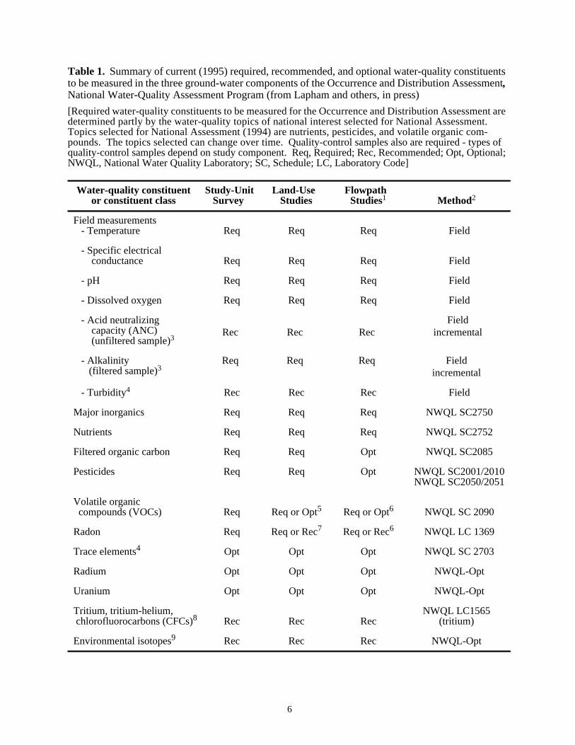
The NAWQA ground-water protocols and recommended procedures are applicable fordata commonly collected for all three ground-water components (Study-Unit Surveys, Land-UseStudies, and Flowpath Studies) of the NAWQA Program (table 1). Although they are consistentwith general guidelines for USGS ground-water data collection (F.D. Wilde, U.S. GeologicalSurvey, written commun., 1995--see footnote 1), these protocols and recommended proceduresreflect NAWQA Program objectives, and could differ in some aspects from those of other USGSprograms. In particular, because of the perennial nature of the NAWQA Program, methods usedby individual Study Units are constrained by the need for national consistency in the quality ofdata collected and by the degree and type of documentation required.
Data-Quality Requirements
The importance of national consistency in data collection cannot be overstated. Inconsis-tent methods can lead to variable and biased data measurements.2 Modifications to collectionand analytical methods potentially result in data whose measurements vary or are biased in re-lation to previously collected data. If not quantified and documented, such modifications com-plicate trend analysis (Smith and Alexander, 1989).
The protocols and recommended procedures for NAWQA are designed to reduce inconsis-tencies and enhance the quality of data used in spatial and trend analysis. The purpose of data-quality requirements is to ensure that data-collection methods are consistent, and that the dataobtained meet study needs. The NAWQA Program has three requirements related to sample col-lection: (1) document the methods used to collect ground-water-quality data and all quality-assurance and quality-control measures, (2) ensure that the quality of data collected is known,and (3) demonstrate that the quality of data obtained is suitable for assessment objectives. Inmeeting these requirements, it is necessary that data-collection and analytical methods be de-signed, planned, and executed as consistently as possible. This will help reduce bias and vari-ability among the data collected within a single Study Unit and among Study Units.
2The term “bias” is defined in this report as a systematic error that is manifested as a consistent positiveor negative deviation from the known or true value. “Variability” is defined as measurement reproducibilityor the degree of similarity among independent measurements of the same quantity, often measured as a vari-ance or relative standard deviation and without reference to the known probable or true value.
6
Table 1. Summary of current (1995) required, recommended, and optional water-quality constituentsto be measured in the three ground-water components of the Occurrence and Distribution Assessment,National Water-Quality Assessment Program (from Lapham and others, in press)
[Required water-quality constituents to be measured for the Occurrence and Distribution Assessment aredetermined partly by the water-quality topics of national interest selected for National Assessment.Topics selected for National Assessment (1994) are nutrients, pesticides, and volatile organic com-pounds. The topics selected can change over time. Quality-control samples also are required - types ofquality-control samples depend on study component. Req, Required; Rec, Recommended; Opt, Optional;NWQL, National Water Quality Laboratory; SC, Schedule; LC, Laboratory Code]
Water-quality constituentor constituent class
Study-Unit Survey
Land-Use Studies
Flowpath Studies1 Method2
Field measurements - Temperature Req Req Req Field
- Specific electrical conductance Req Req Req Field
- pH Req Req Req Field
- Dissolved oxygen Req Req Req Field
- Acid neutralizing capacity (ANC) (unfiltered sample)3
Rec Rec Rec Field
incremental
- Alkalinity (filtered sample)3
Req Req Req Fieldincremental
- Turbidity4 Rec Rec Rec Field
Major inorganics Req Req Req NWQL SC2750
Nutrients Req Req Req NWQL SC2752
Filtered organic carbon Req Req Opt NWQL SC2085
Pesticides Req Req Opt NWQL SC2001/2010NWQL SC2050/2051
Volatile organic compounds (VOCs) Req Req or Opt5 Req or Opt6 NWQL SC 2090
Radon Req Req or Rec7 Req or Rec6 NWQL LC 1369
Trace elements4 Opt Opt Opt NWQL SC 2703
Radium Opt Opt Opt NWQL-Opt
Uranium Opt Opt Opt NWQL-Opt
Tritium, tritium-helium, chlorofluorocarbons (CFCs)8 Rec Rec Rec
NWQL LC1565(tritium)
Environmental isotopes9 Rec Rec Rec NWQL-Opt

7
Table 1. Summary of current (1995) required, recommended, and optional water-quality constituentsto be measured in the three ground-water components of the Occurrence and Distribution Assessment,National Water-Quality Assessment Program (from Lapham and others, in press)--Continued_________________________________________________________________________________
1Selection of constituents for measurement in Flowpath Studies is determined by Flowpath-Study objectives. During at least the first round of sampling, however, the broad range ofconstituents measured in Study-Unit Surveys and Land-Use Studies will be measured.
2Schedules and laboratory codes listed are required for Study Units that began their intensivephase in 1991 or 1994, and apply until changed by National Program directive. Schedules forradium and uranium can be selected by the Study Unit, but require NAWQA Quality-AssuranceSpecialist approval. A detailed discussion is found in the “Sample Collection and Processing”section of this report.
3ANC (formerly referred to as unfiltered alkalinity) is measured on an unfiltered sample.Alkalinity is measured on a filtered sample. A Study Unit could have collected ANC, alkalinity,or both to date.
4Turbidity measurements are required whenever trace-element samples are collected toevaluate potential colloidal contributions to measured concentrations of iron, manganese, andother elements.
5VOCs are required at all urban Land-Use Study wells, but are optional in agricultural Land-Use Studies. If VOCs are chosen as part of an agricultural Land-Use Study, then they should bemeasured in at least 20 of the Land-Use Study wells.
6VOCs are required at all urban flowpath wells for at least the first round of sampling. IfVOCs are measured in an agricultural Land-Use Study, then they should be measured at allFlowpath-Study wells within that Land-Use Study for at least the first round of sampling.
7Radon is required at any Land-Use or Flowpath Study well if that well also is part of a Study-Unit Survey; otherwise radon collection is recommended for Land-Use or Flowpath-Study wellslocated in likely source areas.
8Collection of tritium, tritium-helium, chlorofluorocarbons (CFCs), and (or) other samplesfor dating ground water is recommended, depending on the hydrogeologic setting. For tritiummethods, see NWQL catalog; for CFCs, see Office of Water Quality Technical MemorandumNo. 95.02 (unpublished document located in the USGS Office of Water Quality, MS 412,Reston, VA 22092).
9For a general discussion of the use of environmental isotopes in ground-water studies, seeAlley (1993).

8
This report comprises a substantial part of the documentation requirement. Because of di-verse site conditions, well types, equipment requirements, and staff experience, situations couldarise where NAWQA protocols and recommended procedures described in this report need to bemodified. Modifications at the program level will be made in a systematic manner and initiallydocumented through internal, regional, or national memorandums. For modifications internal toStudy Units, the chief of the Study Unit is responsible for ensuring that the proposed modifica-tion is discussed with the NAWQA Program Quality-Assurance (QA) Specialist before imple-mentation, and that any modifications used are clearly documented in Study-Unit publications.It also is necessary for the NAWQA Program or individual Study Units to provide evidence ofthe effect, or lack thereof, of modifications on data quality.
To ensure data quality and suitability (the second and third data-quality requirements) eachStudy Unit will routinely follow protocols and recommended procedures that are described indetail in the following sections. The QA-QC measures include (1) the collection of selected QCsamples in the field to test equipment and methods before data collection begins, and (2) the rou-tine collection of selected QC samples (such as blanks, replicates, and spiked replicate samples)during ground-water-quality sampling. Additional QC samples and QA measures will be takenif modifications in methods of sample and data collection occur that require quantification.
Individual NAWQA Study Units or National Synthesis teams may find it necessary toexpand QC data collection to identify specific sources of measurement bias or variability. Inaddition, it has been necessary in some cases to enhance collection of QC data in order to inter-pret the corresponding ground-water-quality data (Koterba and others, 1991; Ferree and others,1992; and Koterba and others, 1994). Study-Unit and National-Synthesis-Team budgets, plans,and preparations need to remain flexible to allow for the possibility that additional QC data couldbe needed.
Plans and Preparations
Plans and preparations for ground-water sampling are completed well in advance of data-collection activities, yet must remain flexible enough to be modified if circumstances dictate.Preparations include becoming familiar with the protocols and recommended procedures de-scribed in this document. Sampling equipment and supplies need to be obtained in time for sam-pling and for the staff to be trained in their use. The ground-water staff also needs to becomefamiliar with and develop the documentation and management of samples and data, includingthat for QC samples. Finally, the ground-water staff should make detailed plans and preparationsfor the first field season, which for most Study Units commonly will begin early in the first yearof the Occurrence and Distribution Assessment.
As the Study-Unit Investigation progresses, subsequent plans and preparations for eachfield season are required annually, and are developed as part of the general workplan. StudyUnits commonly will complete preparations for sampling several weeks in advance of each fieldseason. Documenting site conditions, water-quality data collection, and reviewing collected dataare processes that begin before each field season, continue during data collection, and oftenextend months beyond each field season.
9
Five key elements to consider in the initial and (in some cases) annual plans and prepara-tions include (1) site visits to assess conditions that could affect sample and data collection; (2)selecting and obtaining sampling equipment and supplies early, to ensure that those eventuallyused best meet field conditions and fall within NAWQA Program requirements or recommenda-tions; (3) training, to prepare field teams; (4) conducting a field evaluation, to determine that theequipment and procedures will provide high-quality data and that planned documentation andmanagement activities are adequate; and (5) developing detailed schedules that clearly describestaff responsibilities before, during, and after each field season. Each of these planning and prep-aration elements is described below in detail.
Site Visits
Wells selected or installed for each ground-water component are visited at least once beforesampling. During this or any other visit, site data are reviewed to determine if information isneeded to (1) complete documentation requirements (Lapham and others, in press), and (2)plan water-quality sampling activities (table 2). In addition, plans currently (1995) are beingdeveloped for screening wells for high concentrations (10µg/L or greater) of volatile-organic-compound (VOC) contamination (John Zogorski, VOC National Synthesis Team, U.S. Geolog-ical Survey, written commun., 1995). This could add to the information that needs to be collect-ed during these site visits for selected wells sampled after 1995.
Selection and Purchase of Equipment and Supplies
Because of the need to obtain nationally consistent data over many years on a wide varietyof chemical constituents (table 1), most equipment and supplies not provided by the Study Unitgenerally should be obtained from one of three USGS suppliers: the Hydrologic InstrumentationFacility, Quality Water Service Unit, and National Water Quality Laboratory (table 3). Each ofthese suppliers offers the advantage of stocking equipment that otherwise would have to beobtained from multiple sources. These suppliers also conduct QC checks and provide QC datafor selected supplies and equipment distributed to USGS personnel. For these reasons, these sup-pliers are designated as the required or sole-source supplier for such items (table 3, USGS sup-plier with “S” designation). The USGS suppliers also are recommended as sources for otherequipment (table 3, USGS supplier with “R” designation) in order to reduce the time, effort,paperwork, and cost to the Study Unit to locate and obtain equipment. Should the need arise,each supplier also can provide equipment not previously available.

10
Table 2. Information to obtain when planning water-quality data-collection activities______________________________________________________________________________
1. Type of Well Hookup for Sampling: Determine if a hookup to a garden-hose-threadedflow valve (common for water-supply wells) or to a portable, submersible pump (commonfor monitoring wells) is needed for sample collection.
2. Depth Measurements: Measure the depth of the well and depth to the water level in thewell to check well-construction integrity and to determine pump lift, height of water column,volume of standing water held in the well, and purge volume.1
3. Site Conditions and Restrictions: Note road or access conditions to the well, areas oflow clearance, limits on arrival and departure times, or presence of roaming animals (forexample, livestock or pets) that could create problems for a field team.
4. Contact Person: Obtain land- or well-owner name and telephone numbers (business andhome) and contact owner before or upon arrival, and perhaps upon departure.
5. Local Maps and Photographs: Locate well on maps, site sketches, or photographs, andindicate the measuring point for well-depth measurements, as well as areas for equipmentsetup and waste discharge.
6. Travel Maps and Travel Times: Identify route and travel times from District office orprevious site, and possible tunnel or bridge restrictions on the transport of gasoline,bottled gas, or methanol (or other organic cleaning agent).
______________________________________________________________________________1Measurements are made in accordance with National Water-Quality Assessment Program and
U.S. Geological Survey protocols (Lapham and others, in press). Purge volume is defined as threetimes the volume of standing water in the well casing or, in absence of a casing, the borehole.

11
Table 3. Equipment, supplies, and suppliers for ground-water-quality sampling for the NationalWater-Quality Assessment Program
[OM, open market; HIF, U.S. Geological Survey Hydrologic Instrument Facility, Stennis Space Center,Miss.; R, recommended supplier; QWSU, Quality Water Service Unit, Ocala, Fla,; SU, Study Unit;µm,micrometer; mm, millimeter; S, sole (required) source of supplies indicated; NWQL, National WaterQuality Laboratory, Arvada, Colo.; mL, milliliter; L, liter; ASTM, American Society for Testing andMaterials; SC, NWQL analytical schedule; FA, filtered and acidified sample; FU, filtered (unacidified)sample; RU, raw (unfiltered) sample; FCC, filtered, chilled (no preservative added) sample;µS/cm,microsiemens per centimeter at 25 degrees Celsius; mg/L, milligrams per liter; DIW, deionized water;BTD&QS, Branch of Technical Development and Quality Systems, Arvada, Colo.]_____________________________________________________________________________________
Equipment and supplies Suppliers_____________________________________________________________________________________
1. Well-head setup or connection• Monitoring well: submersible pump and reel system OM1
• Water-supply well: hook-up segment with garden-hose thread HIF2, R
2. Sample-flow transfer system from pump reel to collection point• Antibacksiphon device, Teflon, connected in line HIF, R3
• Extension lines for sample flow, Teflon, with connectors HIF, R• Manifold, with connectors and Teflon valves, for routing sample flow HIF, R• Sample-collection equipment that has connectors to manifold:
Radon collector with septa, and connectors to manifold HIF, RGlass syringe with leur-locked stainless-steel needles QWSU, RTeflon, line with connector to manifold, either open ended for turbidity HIF, Rsample collection, or with connector to flowthrough turbidimeter
• Sample-collection and processing chamber frame, PVC or inert HIF, Rmaterial with sample-flow-transfer port
• Preservation-chamber frame, PVC or inert material HIF, R• Transparent disposable covers and plastic clips to hold covers inside SU, HIF, R4
frames for sample and preservation chamber frames• Flowthrough chamber with field-instrument ports, manifold connections, OM5
and waste line
3. Sample-filtration equipmentOrganic carbon, filtered fractions
• Stainless-steel cylinder unit with nitrogen-gas deso-quick connect, gas HIF, Rscrubber, and gas line with connector to secondary regulator
• Nitrogen gas tank, with primary and secondary regulators OM• Filter membranes, 0.45-µm, 47-mm diameter, silver QWSU, S• Safety belts, to secure gas tank OM• Container, to collect spent silver nitrate membranes SU
Pesticides• Aluminum or stainless-steel unit OM, NWQL6
• Filter membranes, 0.7-µm, 142-mm diameter, baked, GF/F gradeglass microfiber QWSU, S
• Connector from filter unit to sample-chamber outflow tube SU6

12
Table 3. Equipment, supplies, and suppliers for ground-water-quality sampling for the NationalWater-Quality Assessment Program--Continued______________________________________________________________________________
Equipment and supplies Suppliers______________________________________________________________________________
Inorganic (major ions, nutrients, and trace elements)• Filter units, capsule with self-contained 0.45-µm7, pleated, Supor capsule QWSU, S• Convoluted (spiral configuration) Teflon sample-flow lines from filter OM
unit to sample-chamber outflow tube8
4. Sample Bottles (sample containers, caps, and protective foam sleeves)
Organic samples• Volatile organic sample (SC2090), 40-mL amber vial, baked (Teflon-
lined cap)--three vials per sample (Also includes trip blanks.) NWQL, S• Pesticides (SC2001 or 2010) sample: 1-L amber bottle, baked (Teflon- QWSU, S
lined cap)• Pesticides (SC2050 or 2051) sample: 1-L amber bottle, baked (Teflon- QWSU, S
lined cap)• Organic carbon (SC2085) samples (filtered): 125-mL, amber bottle, QWSU, S
baked (Teflon-lined cap)• Sleeves, foam, for 40-mL, 1-L, and 125-mL containers QWSU, S
Inorganic samples• Radon (LC1369) sample: scintillation vial (one per transport tube) NWQL, S• Major cations (SC2750): filtered, acid-rinsed, 250-mL clear polyethylene QWSU, S
bottle (with clear cap), FA--two per sample (one archived by SU)• Trace elements (SC2703, SC172, LC112 for arsenic and LC87 for QWSU, S
selenium for field blanks): acid-rinsed, 250-mL clear polyethylenebottle (with clear cap), FA--one per sample
• Major anions (SC2750): 500-mL, clear polyethylene bottle labeled QWSU, S9
FU, clear 28-mm neck (with black cap)--one per sample• Nutrients (SC2752): 125-mL amber polyethylene bottle (with black QWSU, S
cap), FCC--one per sample• Unfiltered sample (SC2750) RU for laboratory measurements: QWSU, S
250-mL clear polyethylene bottle (with black cap)--one per sample(Order black caps for 28-mm bottle neck separately) QWSU, S
5. Sample and Shipping Forms and Shipping Supplies• Field form (standard National Water Quality Field Form or District analog)10SU• Analytical Services Request (ASR) forms for NWQL NWQL, S• Sample Reply Form (Study Unit to NWQL) and return envelope, SU
self-addressed, stamped (see appendix, fig. A20, for example)• Overnight shipping labels Contract Carrier• Surface-mail shipping labels (supplied and prepared at District Office) SU

13
Table 3. Equipment, supplies, and suppliers for ground-water-quality sampling for the NationalWater-Quality Assessment Program--Continued______________________________________________________________________________
Equipment and supplies Suppliers______________________________________________________________________________
• Coolers, with latch lid and drain port, maximum loaded weight of 50-60 lbs. OM(for overnight sample delivery)
• Heavy cardboard boxes, maximum loaded weight, 20 lbs. (surface delivery) OM• Plastic bags, heavy, 4-mil (for holding ice and overnight samples in cooler) OM• Plastic bags, resealable (for holding ASR and other forms mailed with samples) OM• Filament tape (to secure lid and drain cap of cooler, and surface-delivery boxes) OM
6. Field-titration equipment11
• Digital or other titrator meeting USGS specifications QWSU, R• Acid cartridges (for digital titrator)--0.16 and 1.6 Normal sulfuric acid QWSU, S• Extra acid-delivery tubes for digital titrator, clear plastic QWSU, R• Glass beakers (250 mL) OM• Volumetric pipets, glass, Class A (for preparing filtered samples) OM• Magnetic stirrer and small Teflon-coated stir bars OM
7. Field instruments11
• pH (electrometric) meter OM• pH electrodes and refill solutions (specify type of electrode) QWSU, R• Specific electrical conductance meter OM• Dissolved-oxygen (amperometric) meter and associated equipment OM or QWSU
(sensor cable, membrane and solution kit)• Pocket barometer (used for pressure correction to dissolved-oxygen meter) HIF, R• Calibration wand and cup (for dissolved oxygen) HIF, R12
• Turbidity (nephelometric) meter (turbidity measurement generally is OMrecommended, but required for trace-element sampling)
• Temperature measurement: thermistor thermometer (recommended),possibly part of other field meters. Also need a liquid-in-glass QWSU, Rthermometer, ASTM certified, 0.1°C-graduated range of -5 to 45°C OM, R(for calibrating thermistor thermometer)
8. Miscellaneous equipment and supplies• Parafilm HIF, R• Forceps (tweezers), Teflon-tipped stainless steel (to handle filter membranes OM
for organic and inorganic samples); or steel forceps (for flat glass-fiber andsilver membranes) and plastic forceps (for cellulose nitrate or other inorganic-sample membranes)
• Plastic beakers and small cups, used to hold solutions for calibrating or OM, Rchecking field-instrument sensors

14
Table 3. Equipment, supplies, and suppliers for ground-water-quality sampling for the NationalWater-Quality Assessment Program---Continued______________________________________________________________________________
Equipment and supplies Suppliers______________________________________________________________________________
9. Decontamination equipment and supplies• District deionized water (DIW) (conductivity≤1 µS/cm), quality controlled SU• Inorganic-free blank water (IBW) (quality controlled for major ions and QWSU, S13
trace elements)• Pesticide-free blank water (PBW) or volatile and pesticide-free blank NWQL, S13
water (VPBW) (for pesticides or volatile organics)• Methanol, pesticide-grade high purity (organic-sampling equipment) OM• Laboratory detergent, phosphate free, concentrated: diluted to a QWSU, R
0.1 percent decontamination solution, by volume, with DIW• Wash bottles, polyethylene, 250 mL or 500 mL (for DIW and IBW) QWSU, R• Wash bottles, Teflon, 500 mL (for PBW and VPBW) QWSU, R• Wash bottle, for methanol or other organic solvent, 250 mL OM
• Laboratory gloves, powderless (latex or vinyl) (for decontaminationand sample collection) QWSU, R
• Plastic trays (3) HIF, R• Pump standpipes (glass graduated cylinders or pipette jars are preferred) HIF, R14
• Forced-hot-air dryer, portable, vehicle-powered (for evaporating methanol OMresidues)
• Teflon bags, small (for small organic-sampling equipment and pump intake) HIF, R• Heavy aluminum foil (for wrapping organic-carbon and pesticide-filter-unit
inlets and outlets OM• Plastic bags, resealable (for small inorganic sampling equipment) OM• Plastic bags, large, for enclosing cleaned pump reel, extension lines, HIF, R
and other large equipment• Paper tissues, lint free, soft, disposable, large and small sizes (for example, OM
Kimwipes)
10. Safety equipment OM15
• Fire extinguishers (A-B-C type) with mounts• Safety goggles or glasses• Eye-wash bottle• Emergency spill kits for any chemicals being used• Approved containers for transporting pure and used methanol• Safety cones, large• Material Safety Data Sheets
11. Chemical reagents (kits include equipment for dispensing reagent)Preservatives
• VOC samples (SC2090) -- 1:1 hydrochloric acid (kit) NWQL, S• Acrolein and acrylonitrile samples (SC1401) -- 1:1 hydrochloric acid NWQL, S16
• VOC samples in chlorinated water matrix--ascorbic acid (with scoop) NWQL, S17
• Inorganic (FA) samples for major cations (SC2750) and trace elements QWSU, S18
(SC2703)--nitric acid, 1-mL glass ampoule, one per sample

15
Table 3. Equipment, supplies, and suppliers for ground-water-quality sampling for the NationalWater-Quality Assessment Program--Continued_____________________________________________________________________________
Equipment and supplies Suppliers_____________________________________________________________________________
Standards• pH standard buffers (pH 4, 7, and 10) QWSU, S• Specific electrical conductance standards (50 to 50,000µS/cm; for QWSU, S19
low-conductivity waters of≤20 µS/cm, use pH 4.31 buffer)• Turbidity standards--Formazin OM• Dissolved-oxygen “zero” standard dilutions, freshly prepared with OM20
reagent grade sodium sulfite and cobalt chloride
Spike and other solutions• VOCs (SC2090, SC2091, SC2092): standard NAWQA spike solution
and spike-solution kit NWQL, S• Pesticides (SC2050 or 2051 and SC2001 or 2010): standard NAWQA
spike solution and spike-solution kits NWQL, S• Mixtures, required for trace elements (SC2703) BTD&QS, S• IBW, PBW, VPBW (see no. 9, “Decontamination equipment and supplies”) NWQL and
QWSU, S
12. Optional Equipment21
• Equipment for isotope, radiochemical, and other special samples--for example, OMdeuterium-oxygen, tritium, uranium, radium, mercury, chlorofluorocarbons
• Field solid-phase-extraction equipment for pesticide samples NWQL, S_____________________________________________________________________________________________
1That meets NAWQA Program requirements; see text.
2To remove oils and other manufacturing or shipping residues, and before assembling HIF or other equipment that
includes Teflon tubing (without metal fittings), soak tubing for 30 minutes in a 5 percent hydrochloric acid solutionrinsed with tap water until rinsate has pH similar to tap water, then final rinse three times with DIW. For a 5-percentacid solution, add 5 milliliters of 12 normal (concentrated) acid (specific gravity 1.19 and trace-element free) to each100 milliliters of DIW (specific conductance not to exceed 1.0 microsiemens at 25 degrees Celsius).
3Required for each portable pump system (monitoring wells) or hook-up setup (water-supply wells). Purchase
separately from pump system; a single unit can be interchanged between portable-pump and hook-up systems.4Recommended design that allows cover to be attached inside frame with small, plastic clips.
5Flowthrough chamber from HIF meets design criteria for use with individual field instruments--pH, dissolved
oxygen, specific electrical conductance, and temperature--required for ground-water-quality sample collection.6For aluminum filter unit purchased through NWQL that is set up for solid-phase extraction, SU supplies a short
Teflon tube (1/2-inch outer diameter, 3/8-inch inner diameter) that slips over standard nipple connection on filter unitand is connected by a 5/8-inch outer diameter by 1/2-inch inner diameter Teflon sleeve to the tube extending from thesample chamber frame to the filter unit.
7For ground water that contains colloidal material, filter membranes with a pore size less than 0.45µm are
required if the filtrate data must represent ion concentrations in solution. The filter pore size in general should notexceed 0.2µm.
8Commonly sold in 5-foot lengths and can be cut into small lengths. Convoluted is preferred over corrugated
type because latter is prone to trapping sediment, and must be replaced frequently (Johnson and Swanson, 1994).9RU sample is not needed with trace-element schedule SC2703 if field conductivity is recorded on trace-element
ASR form, along with a notation (in comment line to laboratory) that there is “no RU sample.”

16
Table 3. Equipment, supplies, and suppliers for ground-water-quality sampling for the NationalWater-Quality Assessment Program--Continued______________________________________________________________________________
10To be filed with ASR Forms (SU copy) every time samples are collected at well (see appendix, fig. A8, for
example).11
Refer to table 5 and Radtke and Wilde (in press) for descriptions of equipment and equipment specifications.12
Use air-calibration-chamber-in-water method (Radtke and Wilde, in press, Sec. 6.2).13
IBW, PBW and VPBW are laboratory-produced waters quality-controlled for specified analyses. The primaryuse of these waters is for blank samples, but they also can be used in small quantities for ultraclean decontaminationprocedures. PBW and VPBW contain about 0.1 mg/L of organic carbon (NWQL Technical Memorandum 92.01--un-published document available from NWQL, 5293 Ward Road, Arvada, CO 80002), but analyses could differ amonglots.
14Glass is the preferred standpipe material for decontaminating pump equipment because it does not readily absorb
contaminants (Reynolds and others, 1990), especially if used repeatedly after equipment exposure to volatileorganic compounds.
15Contact District Safety Officer for suppliers and specifications.
16Acrolein requires careful acidification to pH between 4 and 5 (acrylonitrile can withstand acidification to pH
less than 2).17
Only required if sample water for VOC analyses is chlorinated; ascorbic acid will be supplied with the VOCpreservative kit (NWQL) upon request. Otherwise, obtain ascorbic acid from the OM. DO NOT SUBSTITUTESODIUM THIOSULFATE for ascorbic acid.
18Ultrapure nitric acid also available in 1-mL glass or Teflon ampoules.
19Purchase standards that bracket water-quality sample values.
20Prepare dissolved-oxygen standard solution fresh on day of use instead of repeatedly purchasing and discarding
commercially available solutions.21
For assistance with (1) isotope, radiochemical, and other specialized equipment, contact the NAWQA QualityAssurance Specialist; (2) solid-phase extraction equipment, contact the NWQL, Methods Research and DevelopmentProgram; and (3) chlorofluorocarbons (CFCs), contact Niel Plummer or Ed Busenberg, USGS National ResearchProgram, MS 432, Reston, VA 22092.
17
Equipment not commonly provided by the Study Unit or USGS suppliers usually can beobtained on the open market (table 3, OM under supplier) and includes portable pumps forcollecting samples at monitoring wells, and field instruments, vehicles, and storage facilitiesassociated with ground-water-quality data collection. Each of these items is discussed separatelybelow.
Pump systems
Several low-discharge, submersible pumps are available for collecting water-qualitysamples from wells. These pumps contain sample-wetted parts that consist mainly of Teflon andcorrosion-resistant 316-stainless steel. On the basis of pump characteristics and results from de-contamination tests (F.D. Wilde, U.S. Geological Survey, written commun., 1995--see footnote1) these pumps are suitable for collecting a wide array of samples, including those required forNAWQA (table 1).
Use of low-discharge, submersible, portable pumps (such as the Fultz Model No. SP-300,Keck Model No. SP-84, Grundfos Model No. Redi-Flo2, and Bennett Model No. 180 or 1800) isrequired for NAWQA when sample collection from monitoring wells involves microgram-per-liter concentrations of VOCs, pesticides, or possibly trace elements. These pumps also are suit-able for the collection of major ion, nutrient, and selected radionuclide samples.
From among suitable pump types, the choice for each Study Unit comes down to weighingthe differences in pump performance characteristics (for example, pump diameter, lift capability,flow rate, portability, repairability, and power requirements) against characteristics of wells inthe network (for example, well internal diameter, accessibility, purge volumes and times, and liftrequirements) to determine the pump(s) that best meet Study-Unit needs. This decision processis illustrated for three pumps and shallow wells (table 4). (A similar process can be used to eval-uate other pumps and deeper wells than those illustrated in table 4.) To select which of thesepumps best meets sampling needs, the Study Unit can compare selected pump characteristics--primarily lift potential and pumping rate--with anticipated well or site characteristics--primarilydepth to water level (lift), purge volume, and purge time (which, for practical reasons, is best keptto less than about 2 hours). If more than one pump type is adequate, other factors, such as repair-ability, power requirements, or cost can be used to refine the selection process. If most wells canbe sampled with one pump type, and only a few wells require a second pump type (for example,deep wells), the Study Unit should consider collaborating with other Study Units or projects with-in the District to obtain the second pump to collect samples. (Well development is not at issue inthis discussion. Pumps to be used for the collection of water-quality samples are not designed,and should not be used, to develop wells.)

18
1Required purge volumes (in gallons) as a function of well diameter and water-column height.
Well diameter Water-column height (in feet) (in inches) 20 40 60 80 100 120 140 160 180 200 240 260
Required purge volume (in gallons)_________________________________________________________
2 10 20 29 39 49 59 69 78 88 98 108 1184 39 78 118 157 196 235 274 313 353 392 431 4706 88 176 264 353 441 529 617 705 793 881 969 1,058
Wherepurge volumeequals three times the borehole or casing volume. The borehole or casing volume,V (in gallons), is calculated as V= 0.0408 x H x D2, where H is thewater-column height (in feet), and Dis the welldiameter (in inches).
2In these examples, therequired lift is equivalent to total dynamic head and is estimated as the depthto water in the well. This assumes that the purge takes place with the pump intake at the top of the watercolumn, and that the water level in the well does not decline appreciably with pumping. Note that for sub-mersible pumps (for example, helical rotor gear, progressing cavity, bladder, and piston pumps) Lift =pump depth + frictional tubing loss; for centrifugal-pump designs, this is more accurately described as totaldynamic head (TDH), where TDH = depth to water + frictional tubing loss.
Table 4. Example of a method to determine pump-system suitability as a function of selected welland pump characteristics[in, inches; ft, feet; gal, gallons; ---, not applicable]
Well characteristics Pump characteristics and suitability
WellDiameter
(in)
Water-columnheight
(ft)
Requiredpurge
volume1
(gal)
Requiredlift ortotal
dynamichead2
(ft)
Maximum pumpedvolume at given lift in2 hours for indicated
pump system3,4 Pump- system suitability5,6
1 2 20 10 25 120 (Fultz SP-300) Suitable
1 2 20 10 25 144 (Keck SP-84) Suitable
1 2 20 10 25 840 (Grunfos Redi-Flo2)
Suitable
2 4 60 118 75 96 (Fultz SP-300) Unsuitable
2 4 60 118 75 132 (Keck SP-84) Suitable
2 4 60 118 75 768 (Grunfos Redi-Flo2)
Suitable
3 2 40 20 160 ---7 (Fultz SP-300) Unsuitable7
3 2 40 20 160 ---7 (Keck SP-84) Unsuitable7
3 2 40 20 160 538 (Grunfos Redi-Flo2)
Suitable

19
Table 4. Example of a method to determine pump-system suitability as a function of selected welland pump characteristics--Continued_____________________________________________________________________________
3Maximum pumped volume is calculated using the pumping rate for a given pump system from man-ufacturer’s specifications at the required lift (or TDH) multiplied by an assumed purging time of 2 hours.
Example pumping rates in gallons per minute (gpm) as a function of lift (TDH) for selected pumpsystems from manufacturer’s specifications. With antibacksiphon device, extension lines, and directional-control flow valves that follow pump-reel system, effective pumping rate is assumed to be 80 percent of thatgiven by the manufacturer. Actual rates, particularly as lifts approach the limit of each system, could be lessthan those specified.
4For practical reasons, and except when quality-control samples are taken, field teams aim to completeall activities at each well within 4 to 6 hours. Thus, purge times generally need to be kept under 2 1/2 hours,with the pumping rate during the last half hour equal to the sampling rate (no more than about one tenth ofa gallon per minute).
5Pump-system suitability is determined as follows:Suitable if themaximum pumped volume at a given lift (or TDH) in 2 hours for the indicated pump
type is equal to or greater than therequired purge volume.Unsuitable if themaximum pumped volume at a given lift in 2 hours for the indicated pump system
is less than therequired purge volume or if therequired lift (or TDH) exceeds the maximum for thepump.
6When two or more pump types meet requirements outlined above, other factors considered in pump se-lection include ability of pump system to be decontaminated adequately, portability, susceptibility of pumpto seizure, ease of repair and use in the field, and cost. It is assumed comparison is among pumps that areconstructed and can be operated in a manner suitable for NAWQA sampling.
7Required lift exceeds maximum lift of the pump; therefore, pump is unsuitable under conditionsgiven in this example.
Lift (in feet)
Pump system 0 25 50 75 100 125 150 175 200 225 250 275
Pumping rate (gpm)
Fultz Model No. SP-300 1.1 1.0 0.9 0.8 0.7 0.5 0.4 --- --- --- --- ---
Keck Model No. SP-84 1.3 1.2 1.2 1.1 1.0 0.9 0.8 --- --- --- --- ---
Grunfos Model No. Redi-Flo2 7.2 7.0 6.7 6.4 6.0 5.7 5.0 4.4 3.8 3.0 2.1 ---
Examplemaximum pumped volume (gal) as a function of lift for the three pump systems given above,assuming pumping time is 2 hours.
Lift (in feet)
Pump system 0 25 50 75 100 125 150 175 200 225 250 275
Maximum pumped volume in 2 hours (in gallons)
Fultz Model No. SP-300 132 120 108 96 84 60 48 --- --- --- --- ---
Keck Model No. SP-84 156 144 144 132 120 108 96 --- --- --- --- ---
Grunfos Model No. Redi-Flo2 864 840 804 768 720 684 600 538 456 360 252 ---

20
Regardless of the pump type chosen, the pump system (pump intake, tubing, and reel) mustmeet certain requirements. The pump can be purchased without an antibacksiphon because asuitable antibacksiphon is to be added by the Study Unit (table 3). The pump line should be sol-id, high-density Teflon tubing. Teflon-lined polypropylene or other tubing is not recommendedbecause the exterior tubing often is not as inert as Teflon. In addition, the outer tubing can sep-arate from the Teflon lining, causing the thin-walled Teflon tubing to pinch or collapse. Suitablepump tubing can be ordered in 50-ft segments connected with 316-stainless steel (SS-316) quickconnections, which makes it possible to use the shortest length of tubing needed for each well.In addition, it is recommended that the reel that holds the tubing be designed to turn (while rais-ing or lowering the pump intake and tubing), while the pump is in operation, and while the pump-reel outlet is connected to an extension line that runs to the remainder of the sample-collectionsetup.
Other types of equipment (bailers, bladder pumps, peristaltic pumps) can be considered forsome site conditions, or special data-collection needs. The use of such equipment generally isnot recommended. Most alternative sample-collection devices are either limited in their liftpotential, constructed of materials that are unsuitable or difficult to decontaminate, or deliver thesample in a manner (for example, under suction) that they cannot be used for most sites, or donot provide data of suitable quality for all NAWQA constituents (F.D. Wilde, U.S. GeologicalSurvey, written commun., 1995--see footnote 1).
Study Unit staff that need to collect ground-water-quality samples using equipment otherthan that specified (table 3) must discuss their plans with the NAWQA QA Specialist. At a min-imum, it is expected that sufficient QC data are available, or will be collected, to verify that theground-water data obtained with the alternative equipment is similar in quality to data beingobtained by the NAWQA Program in general.
Field instruments
Each Study Unit is to obtain suitable field instruments to collect data for pH, specific elec-trical conductance (SC), dissolved oxygen (DO), and temperature (T). If samples for traceelements (such as iron, manganese, aluminum, or uranium) are collected, sample turbidity (TU)also is measured. These data (pH, SC, DO, T, and possibly TU) are part of the required water-quality record for each ground-water sampling site (table 1), and also serve as QC measures thatare used to assess the chemical variability of water before and at the time samples for otherchemical constituents are collected. In collecting these data, however, the field instruments usedmust meet certain requirements (table 5).

21
1Slope test and temperature correction are described in Radtke and Wilde (in press).2Use spectrophotometric or iodometric method for accurate measurements of dissolved-oxygen
concentrations less than 1 mg/L (Radtke and Wilde, in press).
Table 5. Requirements for meters and sensors used for field measurements taken at ground-water-quality sites of the National Water-Quality Assessment Program (modified from Radtkeand Wilde, in press)
[°C, degrees Celsius; mV, millivolt; ∆mv/∆pH, change in millivolts divided by change in pH at measure-ment temperature (in°C); ≥, greater than or equal to; µS/cm, microsiemens per centimeter at 25°C;≤, less than or equal to; >, greater than; mg/L, milligrams per liter; NTU, nephelometric turbidity units;NWIS-I, National Water Information System-I]
Field measurement Performance requirements
Temperature (°C)(recommend thermistor-type thermometer)
Reading to 0.1°C for temperatures from -5 to 45°C; bias within0.2°C. (Requirement applies to any thermistors used in associ-ation with other field measurements, including those containedin other field-measurement systems. Sampling thermal systemscan require readings and calibration to 52°C.)
pH (standard units; requireelectrometric method)and field titrations
Reading to 0.1 standard unit (or 0.05 unit for instruments thatdisplay more than two digits to the right of the decimal). Tem-perature compensating; mV readout; rapid electrode response--maximum 15- to 20-second elapsed time for reading to “lock-on” the low pH calibration buffer after meter is calibrated withhigh pH 7 buffer; pH electrode must pass slope-test [(∆mv/∆pH) ≥ 0.94 x (Theoretical Nernst slope)], corrected for temper-ature.1
Specific electricalconductance(µS/cm at 25°C)
Reading within 5 percent of full scale at≤100µS/cm or within3 percent of full scale at >100µS/cm; temperature compensa-tion range from -2 to 45°C or greater, if needed. Instrumentmust compensate for temperature to provide readings at 25°C,or temperature readings are required to apply correction factorand report measurement at 25°C.
Dissolved oxygen2
(require amperometricmethod)
Reading to 0.3 mg/L or less for concentrations≥1 mg/L. Tem-perature compensation and temperature measurement required.Field barometer needed to determine barometric pressurecorrection factor.
Turbidity (recommendnephelometric method)
Select instrument designed to provide precise and unbiasedmeasurements at 0 to 40 NTU. Reading within 5 percent fullscale for 1 to 500 NTU, and within 0.02 NTU for turbidity lessthan 1 NTU. Turbidity entered into the NWIS-I data base mustbe made using nephelometric measurements.

22
Water levels are to be determined whenever possible before other water-quality data arecollected from wells (Lapham and others, in press). The static water level within a few hundredfeet below land surface is measured using a chalked steel tape, and the measurement is repeateduntil two consecutive measurements differ by no more than 0.02 ft, or until the reason for lessprecise measurements is determined and documented. In addition, the depth from land surfaceto the bottom of the well is measured during each site visit whenever possible to verify the integ-rity of the well construction.
Each field instrument must be calibrated, operated, maintained, and stored, and the neces-sary calibration and test results documented according to USGS protocols. The protocols forground-water-quality field measurements are described in Radtke and Wilde (in press).
Water-quality vehicles
Different vehicle designs will be used among Study Units because of differences in terrain,accessibility of sites, travel distances, trip duration, and other factors. In selecting and modifyinga vehicle for water-quality data collection, however, it is recommended that safety and qualitycontrol be given high priorities. Study Unit staff also are encouraged to research designs alreadyin use and to dedicate vehicle(s) solely to the collection of water-quality data.
Safety is a vital concern. The most important thing a water-quality vehicle will carry is thefield team. To protect the team, all equipment is secured and properly stored behind passengerbarriers when in transit, and without affecting the driver’s visibility. In addition, vehicle suppliesshould include safety cones; safety glasses; fire extinguishers; first-aid, eye-wash, and chemical-spill kits; and Material Safety Data Sheets--all placed where they are readily accessible. If sam-ple collection or processing occurs inside the vehicle, ventilation must be adequate and theremust be sufficient room to operate. Flex hose is used to vent combustion exhaust away from avehicle that is stationary with the engine running, and is stored and transported outside of thesampling vehicle. Flammable solvents (such as methanol) and pressurized gases (such as nitro-gen) are transported according to local and State regulations. Regular service and maintenanceand before-departure safety inspections of the vehicle are scheduled by the field team. If ques-tions arise in regard to safety or inspection procedures, methods, or equipment, contact theDistrict safety officer.
Quality assurance of the sampling vehicle is critical to a successful investigation. Thisvehicle should enable the field team to collect high-quality samples and data. Despite diverseexternal conditions, the vehicle should provide a clean environment for sampling and equipment,and a suitable environment for protecting equipment from damage during transport. The vehicledesign also should provide temporary protection of field instruments, chemical reagents, buffers,preservatives, standards, and most water-quality samples from extreme heat and cold. It alsomust provide for the temporary (and contaminant-free) storage of some samples (VOCs, pesti-cides, nutrients), and some reagents (for example, spike solutions for pesticides and VOCs andVOC acid preservative) at near-freezing temperatures. If the vehicle interior is used for the col-lection or processing of water-quality samples, then adequate lighting, plumbing, and counterspace are needed. Sample collection and preservation chambers are used whether working insideor outside the vehicle. These reduce contamination of and from the vehicle interior.
23
Obtain and design vehicles that can be dedicated solely to water-quality sampling. Avehicle used for water-quality data collection is not used for the storage (even temporary) of agenerator using gasoline or other types of fume-producing fuels, or of heavily soiled equipment,clothing, or tools. Nor should a vehicle previously used for such storage be converted to a water-quality vehicle. One might even question the adoption of a used water-quality vehicle if sampleswere collected and, in particular, preserved within the vehicle without regard to possible vehiclecontamination. In each case above, there is a risk that the vehicle will be, or has been, perma-nently contaminated.
Storage facilities
Field vehicles are not suitable for storage of most supplies and some equipment used forwater-quality data collection. When not in operation, the vehicles cannot provide adequate pro-tection from extreme heat or cold, which can destroy or degrade chemical standards, buffers, andother reagents, as well as damage some field instruments. Especially during extremes in tem-perature, remove sensitive supplies and equipment from an idle vehicle to a safe indoor locationon a daily basis. Clean and secure facilities, which are separate from those used for other typesof NAWQA equipment (such as generators, fuel, drilling supplies and materials, and permanent-ly soiled gear), are needed for longer periods of storage.
Timing of purchases
Durable equipment and supplies (such as vehicles, pump systems, plastic bottles) areordered well in advance of the first field season, and thereafter on an as-needed basis. Beginvehicle purchase and modification(s) 12 to 14 months before the vehicle is needed for water-quality data collection. Nonperishable, and limited quantities of perishable supplies (see below)are purchased and on hand at least 3 to 6 months before water-quality data collection begins.Pump systems and other sample-collection equipment also can take up to several months toobtain, assemble, and modify to complement vehicle design.
Some supplies, such as most chemical solutions, have a limited shelf life. As part of theirplanning, Study Units should (1) follow manufacturer’s recommendations on storage, and (2)query their suppliers about shelf life for any preservatives, buffers, standards, and reference sam-ples, as well as for blank, spike, surrogate, and instrument-sensor solutions, or any other chem-ical reagents. This will prevent overstocking and reduce waste. Upon receiving these supplies,the date of receipt and the expiration date should be marked clearly on time-sensitive supplies.Study Units also are required to record supply lot numbers. Without these records, the QA andQC information that exists for these supplies, and provided by lot number, cannot be utilized bythe Study-Unit or NAWQA National Program. This is one of the quality-assurance measuresthat could be needed to correctly interpret water-quality QC data.
Study-Unit staff are likely to select the most appropriate vehicle design, pump system, andrelated equipment after information from site visits is obtained, and after sampling teams havehad some training (see “Training” below). Following training, the field teams need their equip-ment and supplies for practice, and to verify that they are suitable for water-quality data collec-

24
tion (see “Field Evaluation” below). Therefore, most nonperishable equipment and supplies needto be on hand at least 3 to 6 months in advance of the first field season of data collection.
Training
Modifications in USGS protocols and recommended procedures (F.D. Wilde, U.S. Geolog-ical Survey, written commun., 1995--see footnote 1), and the need for consistency dictate thattraining in the collection and management of water-quality data is required for most Study-Unitstaff. This training is to be obtained through USGS Level I courses and field experience, ideallybefore water-quality data collection begins (table 6).
Field Evaluation
Each Study Unit is required to test and evaluate the sample-collection equipment and pro-cedures that commonly will be used (table 6, no. 4). This is separate from, and occurs after, thefield training with Study-Unit equipment. To avoid unnecessary delay in planned data collectionwhile awaiting laboratory results, this test should be conducted at least 2 months before sampleand data collection begin. Ideally, the evaluation can occur toward the end or after the field ex-ercise devoted to equipment shakedown and cross-training (table 6, no. 3).
To conduct the test, the Study Unit selects a well with measurable concentrations of asmany of the following contaminants as possible: VOCs, pesticides, nutrients, and (if targeted forinvestigation by the Study Unit) trace elements. The field team collects samples for all constit-uents (in the order and manner in which samples commonly are going to be collected--see “Sam-ple Collection and Processing”). After sample collection, equipment is decontaminated. Fieldblanks for all constituents are collected with the decontaminated equipment. Two field-spiked,blank samples are prepared for the VOC schedule and for each pesticide schedule. One blanksample for the VOC schedule is spiked by one field-team member, and its replicate is spiked bythe other field-team member. One field-team member also spikes the blank sample for one pes-ticide schedule; the other field-team member spikes the other blank sample for the second pesti-cide schedule. (Definition of QC samples is provided in “Design of Quality-Control Samplingand Schedules.”) All ground-water-quality samples and QC samples are sent to the NWQL foranalysis.
Data from the ground-water-quality and QC samples are evaluated by the Study Unit, andthe evaluation and data are forwarded as soon as possible to the National Program (NAWQA QASpecialist). These data are to confirm that (1) the ground water contained measurable levels ofsome contaminants, (2) decontamination procedures removed contaminants from equipment, and(3) the procedures used to prepare spiked blanks led to acceptable recoveries of selected VOCsand pesticides.
The evaluation assures the field team, Study Unit, and National Program that the protocolsand procedures are satisfactory. Potential problems identified by the Study Unit(s) are correctedbefore sample and data collection begins.
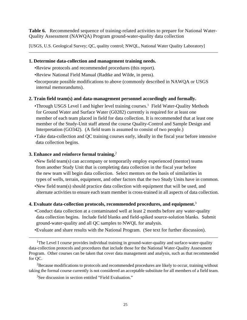
25
Table 6. Recommended sequence of training-related activities to prepare for National Water-Quality Assessment (NAWQA) Program ground-water-quality data collection
[USGS, U.S. Geological Survey; QC, quality control; NWQL, National Water Quality Laboratory]______________________________________________________________________________
1. Determine data-collection and management training needs.•Review protocols and recommended procedures (this report).
•Review National Field Manual (Radtke and Wilde, in press).
•Incorporate possible modifications to above (commonly described in NAWQA or USGSinternal memorandums).
2. Train field team(s) and data-management personnel accordingly and formally.
•Through USGS Level I and higher level training courses.1 Field Water-Quality Methodsfor Ground Water and Surface Water (G0282) currently is required for at least onemember of each team placed in field for data collection. It is recommended that at least onemember of the Study-Unit staff attend the course Quality-Control and Sample Design andInterpretation (GO342). (A field team is assumed to consist of two people.)
•Take data-collection and QC training courses early, ideally in the fiscal year before intensive data collection begins.
3. Enhance and reinforce formal training.2
•New field team(s) can accompany or temporarily employ experienced (mentor) teamsfrom another Study Unit that is completing data collection in the fiscal year beforethe new team will begin data collection. Select mentors on the basis of similarities intypes of wells, terrain, equipment, and other factors that the two Study Units have in common.
•New field team(s) should practice data collection with equipment that will be used, andalternate activities to ensure each team member is cross-trained in all aspects of data collection.
4. Evaluate data-collection protocols, recommended procedures, and equipment.3
•Conduct data collection at a contaminated well at least 2 months before any water-qualitydata collection begins. Include field blanks and field-spiked source-solution blanks. Submitground-water-quality and all QC samples to NWQL for analysis.
•Evaluate and share results with the National Program. (See text for further discussion).______________________________________________________________________________
1The Level I course provides individual training in ground-water-quality and surface-water-qualitydata-collection protocols and procedures that include those for the National Water-Quality AssessmentProgram. Other courses can be taken that cover data management and analysis, such as that recommendedfor QC.
2Because modifications to protocols and recommended procedures are likely to occur, training withouttaking the formal course currently is not considered an acceptable substitute for all members of a field team.
3See discussion in section entitled “Field Evaluation.”

26
Design of Ground-Water-Quality Sampling Schedules
As part of planning for field sampling, schedules are prepared annually or more frequently,if needed, for the collection of ground-water-quality and QC data for each ground-water compo-nent (Study-Unit Survey, Land-Use Study or Flowpath Study) targeted for investigation eachyear. These schedules list the daily activities for the field team, data managers, and support staff.
For ground-water-quality samples, the schedule describes the timing and order in whichwells for each ground-water component are targeted for data collection (table 7). General sched-uling considerations include component factors, travel times, personnel requirements, and siteconditions (table 8). Each schedule is designed over a period of several months, and before anyground-water-quality samples are collected.
Study Units will pay particular attention to factors that enhance the consistency and qualityof samples and data obtained and provide the Study Unit and National Program with the neces-sary data to determine the quality and suitability of data collected for NAWQA assessments(table 9). The design and scheduling of QC data collection, which are critical and integral partsof water-quality data and data collection (Shampine and others, 1992), are discussed in detail inthe next section. For most of the other factors (tables 8 and 9), it is assumed that the informationneeded is obtained through staff planning meetings and site visits conducted before data collec-tion begins.
As a general rule, except for Flowpath Studies, most Study Units will find that a single,two-person field team often needs a day to conduct data-collection activities at one well. Withexperience, and under the optimum field conditions, some teams will be able to collect data frommore than one well per day. In the case of Flowpath Studies, the close proximity and shallowdepths of wells also could permit sampling at more than one well per day. In addition, wellstargeted for QC data collection could require an additional team member to complete activitiesin a single day.

27
Table 7. Example of a sampling schedule for a 28-well Land-Use Study
[Assumes (a) one (two-person) field team generally collects samples on a weekly run (Monday-Thursday);(b) incorporation of general scheduling considers component factors, travel times, personnel, and siteconditions (table 8), as well as requirements to enhance data quality (table 9); and (c) routine quality-controlsampling occurs at selected wells distributed throughout the collection period (third person possibly joinsteam). SRS, standard reference samples for trace elements; VOC, volatile organic compound]____________________________________________________________________________________________
Period of activity Activity to be conducted by team____________________________________________________________________________________________
Week 1 Day 1 (M) Depart for Well 1: collect ground-water (GW) samples. 2 (T) Well 2: Collect GW and quality-control (QC) samples. 3 (W) Well 3: Collect GW samples. 4 (Th) Well 4: Collect GW samples, return to office, unload vehicle. 5 (F) Evaluation and preparation: Study Unit reviews progress, plans, sampling
schedule, and completes final preparations for following week’s activities.
Week 2 Days 8-12 Wells 5-8: Similar schedule as week 1, but without QC data collection.
Week 3 Day 15 (M) Well 2: Review QC data and continue sampling if no problems appear;decision to sample two wells per day when possible is made.
16 (T) Team and staff complete preparations, team departs office. 17 (W) Well 9: Collect GW and QC samples (including one SRS). 18 (Th) Wells 10 and 11: Collect GW samples. 19 (F) Team returns to office and, aided by staff, unloads and cleans vehicle.
Week 4 Days 22-26 Wells 12-15: Similar to schedule for week 2.
Week 5 Day 29 (M) Well 9: Review QC data and continue sampling if no problems appear.Team, aided by staff, completes preparations, and departs office.
30 (T) Wells 16 and 17: Collect GW samples. 31 (W) Well 18: Collect GW samples. 32 (Th) Well 19: Collect GW and QC samples (with VOC trip blank, as planned);
team returns to office late in day. 33 (F) Team and staff unload, clean, and restock vehicle.
Week 6 Days 36-40 Wells 20-23: Similar to schedule for week 2.
Week 7 Day 43 (M) Well 24: Team departs office, collects GW samples. 44 (T) Well 25: Collect GW samples. 45 (W) Wells 26 and 27: Collect GW samples. 46 (Th) Well 28: Collect GW and QC samples, team returns to office
and with staff unloads and cleans vehicle. 47 (F) Vehicle goes in for regular service and maintenance.
Week 8 Day 50 (M) Team and staff receive QC data (wells 19 and 28). If QC data aresatisfactory, sample collection continues unabated. Team andstaff prepare for next component to be sampled. Remaining twoSRS samples needed for the year will be included in data collectionfor the next component.
_____________________________________________________________________________________________

28
Table 8. Basic considerations in designing annual ground-water-quality sampling schedules forStudy-Unit components (Land-Use Studies, Study-Unit or Subunit Surveys, and FlowpathStudies) of the National Water-Quality Assessment Program______________________________________________________________________________
1. Component factors• Number of each type of component.• Number of wells per component.
2. Travel times• Between office and wells.• Between wells.• Between well and overnight shipping sites.
3. Personnel• Number of field teams.• Number of individuals per team (generally consider two members; possibly third person
at wells that include QC sample collection).• Experience of personnel in team.• Office staff support.
4. Site and seasonal conditions• Equipment setup time (water-supply or monitoring well).• Purge time.• Data-collection requirements (ground-water quality only or ground-water quality
and quality control).• Duration of field season.
______________________________________________________________________________
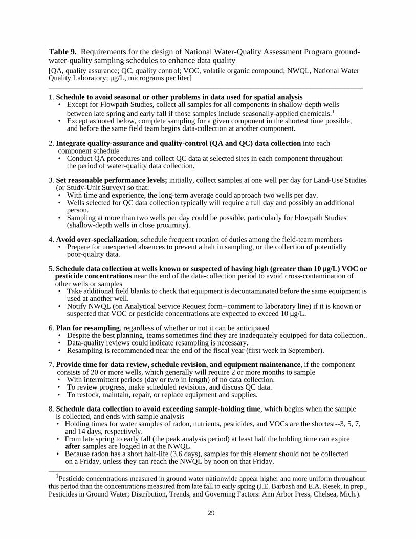
29
Table 9. Requirements for the design of National Water-Quality Assessment Program ground-water-quality sampling schedules to enhance data quality[QA, quality assurance; QC, quality control; VOC, volatile organic compound; NWQL, National WaterQuality Laboratory;µg/L, micrograms per liter]____________________________________________________________________________________
1. Schedule to avoid seasonal or other problems in data used for spatial analysis• Except for Flowpath Studies, collect all samples for all components in shallow-depth wells
between late spring and early fall if those samples include seasonally-applied chemicals.1
• Except as noted below, complete sampling for a given component in the shortest time possible,and before the same field team begins data-collection at another component.
2. Integrate quality-assurance and quality-control (QA and QC) data collectioninto eachcomponent schedule• Conduct QA procedures and collect QC data at selected sites in each component throughout
the period of water-quality data collection.
3. Set reasonable performance levels;initially, collect samples at one well per day for Land-Use Studies (or Study-Unit Survey) so that:
• With time and experience, the long-term average could approach two wells per day.• Wells selected for QC data collection typically will require a full day and possibly an additional
person.• Sampling at more than two wells per day could be possible, particularly for Flowpath Studies
(shallow-depth wells in close proximity).
4. Avoid over-specialization; schedule frequent rotation of duties among the field-team members• Prepare for unexpected absences to prevent a halt in sampling, or the collection of potentially
poor-quality data.
5.Schedule data collection at wellsknown or suspected of having high (greater than 10µg/L) VOC orpesticide concentrations near the end of the data-collection period to avoid cross-contamination ofother wells or samples• Take additional field blanks to check that equipment is decontaminated before the same equipment is
used at another well.• Notify NWQL (on Analytical Service Request form--comment to laboratory line) if it is known or
suspected that VOC or pesticide concentrations are expected to exceed 10µg/L.
6. Plan for resampling, regardless of whether or not it can be anticipated• Despite the best planning, teams sometimes find they are inadequately equipped for data collection..• Data-quality reviews could indicate resampling is necessary.• Resampling is recommended near the end of the fiscal year (first week in September).
7. Provide time for data review, schedule revision, and equipment maintenance, if the componentconsists of 20 or more wells, which generally will require 2 or more months to sample• With intermittent periods (day or two in length) of no data collection.• To review progress, make scheduled revisions, and discuss QC data.• To restock, maintain, repair, or replace equipment and supplies.
8. Schedule data collection to avoid exceeding sample-holding time, which begins when the sampleis collected, and ends with sample analysis• Holding times for water samples of radon, nutrients, pesticides, and VOCs are the shortest--3, 5, 7,
and 14 days, respectively.• From late spring to early fall (the peak analysis period) at least half the holding time can expire
after samples are logged in at the NWQL.• Because radon has a short half-life (3.6 days), samples for this element should not be collected
on a Friday, unless they can reach the NWQL by noon on that Friday._____________________________________________________________________________________
1Pesticide concentrations measured in ground water nationwide appear higher and more uniform throughoutthis period than the concentrations measured from late fall to early spring (J.E. Barbash and E.A. Resek, in prep.,Pesticides in Ground Water; Distribution, Trends, and Governing Factors: Ann Arbor Press, Chelsea, Mich.).

30
Design of Quality-Control Sampling and Schedules
Each Study Unit is required to collect similar types of QC samples (table 10). Those thatare collected regularly throughout each field season are referred to as “routine QC samples.”Additional QC samples, referred to as “topical QC samples,” occasionally could be collected bysome or all Study Units to isolate and resolve problems or evaluate modifications to NAWQAfield methods.
The data obtained from routine or topical QC sampling are used to estimate the potentialbias (either from contamination or in recovery) and measurement variability for selected ana-lytes. Routine QC samples provide the data required by the NAWQA Program to make generalinferences about bias and variability for all water-quality data collected. Bias and variabilitymeasurements from routine QC samples reflect combined field and laboratory errors that occurduring data collection. Measurements obtained from topical QC sampling will reflect errorsassociated with a specific field or laboratory procedure employed by NAWQA and targeted forstudy.
Study Units can use QC data in several ways. Those that can derive bias and variabilityestimates from routine QC sampling in a timely manner can use the results not only to assess thequality of data being collected, but also, in some cases, to identify wells that need to be resampled(Koterba and others, 1991). In the case of topical QC data, sources of sample contamination orbias that occur as a result of sample collection and processing, initially identified through routineQC sampling, can be isolated and eliminated (Rea, in press; Koterba and others, 1991).
Bias and variability estimates also can be used during data analysis and interpretation ofground-water-quality data. For each ground-water component, the magnitude of these error es-timates provide an indication of the quality of ground-water data collected (Koterba and others,1991 and 1993). In addition, as water-quality data from different Land-Use Studies or SubunitSurveys are compared, contrasted, or combined, the corresponding routine estimates of bias andvariability from QC data also can be compared, contrasted, and combined to make inferencesabout the quality and suitability of the aggregated water-quality data that are being used forStudy-Unit or National Assessments.
In some cases, data analysis and interpretation can depend on the timely analysis of routineand topical QC data obtained in the field combined with timely discussion of these data with theNational Program and the NWQL. Examples of the above, which led to modifications in Study-Unit field methods and in the QC sampling design, and ultimately improved data quality, analy-sis, and interpretation include studies by Ferree and others (1992) and Koterba and others (1994).Their experience indicates how critical it is for Study-Unit plans to remain flexible. These plansmust allow for the possible modification of the initial designs for routine QC sampling (as de-scribed below), or the methods used to collect these and ground-water-quality samples (de-scribed later in this report). Such modification could prove critical to correctly identifying theoccurrence and distribution of contaminants in ground water and their relation to Study-Unitlandscape and subsurface features.

31
Table 10. Quality-control samples for ground-water components of the NationalWater-Quality Assessment (NAWQA) Program
[Definitions are consistent with those of the U.S. Geological Survey Branch of Technical Develop-ment and Quality Systems (BTD&QS) and the Office of Water Quality. NWQL, National WaterQuality Laboratory; VOCs, volatile organic compounds]
Sample type Description Purpose
1. Blanks1 Types include field, source-solution, and trip.
Assess bias from contamination ofblank water.
•Field Blank water passed throughequipment in the field, and col-lected in a manner similar to thatused to collect water-qualitydata, but after equipment is usedand decontaminated.
Verify that decontamination proce-dures are adequate, and that fieldand laboratory protocols and rec-ommended procedures do notcontaminate samples.
•Source solution2 Blank water placed directly in thesample container, but in a cleanenvironment.
Verify that blank water is contami-nant-free just before it is used for afield blank.
•Trip Blank water placed in samplecontainer by NWQL, shipped tostudy with empty containers, andreturned unopened by Study Unitfrom field for analysis.
Verify that shipping, handling, andintermittent storage of containersdoes not result in contamination orcross-contamination of samples.
2. Replicates3 Two or more ground-water-quality samples collected sequen-tially for the same analytes.
Assess combined effects of fieldand laboratory procedures onmeasurement variability.
3. Field spikes4 Types include samples preparedfrom blank water or from groundwater.
Assess recovery bias of analytes inspike solution.
•Source-solutionwater5
Two source-solution blanks towhich identical volumes of spikesolution are added, but by differ-ent members of field team. ForVOCs, preserve with NWQLacid before spiking.
Verify equipment and proceduresfor field spiking, handling, ship-ping, and analysis lead to similarresults among Study Units.
•Ground water Two or more replicate ground-water-quality samples to whichidentical volumes of spike solu-tion are added in a manner thatdoes not substantially alter sam-ple matrix. For VOCs, preservewith NWQL acid before spiking.
Assess recovery bias and variabil-ity in relation to different ground-water matrices.

32
1Blank water is certified by supplier as free of analytes of interest at concentrations thatexceed NAWQA detection or reporting level. A trip blank is only required for VOCs.
2Because blank solutions are not regularly analyzed for dissolved organic carbon (DOC),source-solution blanks are required along with field blanks for this analyte. A source-solution blankfor DOC is required each time a field blank for DOC is taken.
3Chemical composition of water entering the well and being collected is assumed constantduring time needed to collect sequential samples (including replicates).
4Spike solutions for NAWQA contain either selected VOC or pesticide analytes; solutionsare obtained and used in accordance with instructions from the NWQL. At least one unspiked(background) ground-water sample from the same well used to obtain the samples for fieldspikes is analyzed in conjunction with field-spiked samples (see text).
5Preserved and spiked source-solution blanks for pesticides and VOCs are prepared onlyas part of the initial evaluation of equipment and procedures before data collection begins.
Sample type Description Purpose
4. Standard reference (mixtures)
Prepared by BTD&QS as mix-tures, sent to Study Units collect-ing trace-element samples,shipped unopened from field toNWQL for analysis.
Assess recovery bias andvariability of selected traceelements.
Table 10. Quality-control samples for ground-water components of the NationalWater-Quality Assessment (NAWQA) Program--Continued

33
Routine quality-control samples: type, number, site selection, and timing
The current NAWQA QC sampling design for ground water is based on the integrated ap-proach described by Shampine and others (1992). Under this design, it is recommended that eachStudy Unit follow similar procedures (tables 11 and 12) to identify (1) the types of routine QCsamples collected, (2) the wells at which these samples will be obtained, and (3) the timing ofQC sample collection for each of the ground-water components scheduled for data collection ineach field season. These procedures ensure that the data obtained for each routine QC sampletype (1) represent major differences in the major ion chemistry (sample matrix) of ground watertargeted for study, (2) are suitable for estimating measurement bias and variability for the ana-lytes of interest, and (3) reflect possible temporal variations in field and laboratory methods dur-ing the time period that ground-water-quality data are collected (table 13).
It would be ideal in terms of planning, efficiency in the field, and costsif similar routineQC designs could be used forall ground-water components. Because Land-Use Studies, Study-Unit (or Subunit) Surveys, and Flowpath Studies differ in their design and scope, the types andnumbers of routine QC samples, the wells selected for collecting these samples, and the timing ofvisits to the wells selected will differ somewhat among these components.
It would be ideal in terms of planning, efficiency, and costs ifall routine QC samples couldbe collected at thesame well sites for each ground-water component. Representative and suit-able QC data, however, often can only be obtained by scheduling the collection of different typesof routine QC samples at different wells within a given component (see below), or, in the case ofthe VOC trip blank and (possibly) trace-element standard reference samples, at wells selectedfrom among several components sampled in the same field season (table 13, footnote 1).
Land-Use Studies.A typical Land-Use Study is focused primarily on one major land-useclassification, and for ground water, involves the collection of samples for a variety of analytes(table 1) from each of a relatively small number of wells (about 30, including reference wells)completed at shallow depths and often in a single aquifer. Therefore, a typical design for routineQC data collection requires the collection of many different QC sample types to cover the varietyof analytes being investigated (table 12). It also requires a minimal number of samples for eachQC-sample type because differences in the quality of ground water among wells are assumed toreflect chiefly the intensity of a single land use on the shallow part a single aquifer.
Some wells in the Land-Use Study will need to be chosen (if possible, and according tomethods described later in this section) specifically to collect the required number of routine, rep-licate ground-water samples and routine field blanks (table 13). These wells are chosen, in part,because they are likely to provide samples with measurable (greater-than-method-reporting-level) concentrations. (Estimating the variability of measurements for a given analyte usingreplicate samples requires that these samples contain measurable, greater-than- or equal-to-method reporting-level concentrations for that analyte.) They also are selected, if possible, toprovide a range in measurable concentrations that reflect the effects of that land use on shallowground-water quality.

34
Table 11. Procedures to identify the type and schedule the annual collection of routine quality-control data for ground-water components of the National Water-Quality Assessment Program_____________________________________________________________________________
1. Identify analyte groups for which water-quality data will be collected that field season
• On the basis of national requirements (table 1).
• To which are added local Study-Unit interests, such as trace elements.
2. Identify routine quality-control (QC) data to be collected
• On the basis of the Study-Unit component (for example, see table 12).
• Determine QC sample types by analyte group to be collected.
• Determine number (or frequency) of each type to be collected.
3. Identify wells and develop schedules for routine QC data collection for each
component1
• Select wells to provide suitable and representative QC data (see text and table 13).
• Schedule visits to these wells to provide QC data collection for each analyte group
throughout the months that water-quality data for that analyte group and component
are being collected (see text and table 13).
_____________________________________________________________________________1If volatile-organic-compound (VOC) and trace-element samples are collected during a given
field season, then at least one VOC trip blank, in addition to field blanks and spiked replicate samples,and at least three trace-element standard-reference samples are sent from the field to the NationalWater Quality Laboratory for analysis.

35
Table 12. Required type and minimum number (or frequency) of routine quality-controlsamples for a Land-Use Study of the National Water-Quality Assessment Program
[Field blanks and field-spiked, source-solution blanks taken during the evaluation of methods are not includedbelow. Assume study consists of 25 to 30 wells. Trace-element field blanks use National Water Quality Laboratory(NWQL) Schedule SC172 with selenium (LC0087) and arsenic (LC0112). All other routine quality-control samplesuse the same NWQL schedule or laboratory code used for the corresponding water-quality samples. DOC, dissolved(filtered) organic carbon; ALK, alkalinity (field-titration, filtered ground-water sample); and ANC, acid-neutraliz-ing capacity (field titration, unfiltered ground-water sample; VOCs, volatile organic compounds]_____________________________________________________________________________________________
Routine quality-controlAnalyte groupa sample type Required number (frequency)
_____________________________________________________________________________________________
1. Commonly present in Field blanks Minimally at 2, but preferablymeasurable concentrations: at 3, well sites.major ions, nutrients, andDOC. (ALK and ANC-- Source-solution blanks (Every time a DOC field blankreplicates only) is taken, only for DOC.)
Replicate (2) ground- Minimally from 2, but prefer-water samples per well ably from 3 wells at different
sites.
2. Commonly present inmeasurable concentrationsin some, but usually not all,areas:
• Pesticides or VOCs Field blanks Minimally at 2, but preferablyat 3, well sites.
Trip blank (One per field season, only forVOCs.)
Field-spiked, replicate Minimally at 2 well sites.(2) samples per well
• Trace elements (such as Field blanks Minimally at 3 to 5 well sites.c
NWQL SC2703)b
Standard-reference- (Three per field season.)sample mixtures
Replicate (2) ground- Minimally from 3 to 5 wellssamples per well at different sites.
• Radionuclides (such as Replicate (2) ground- Minimally from 3 wells atradon) samples per well different sites.
____________________________________________________________________________________________aFor tritium, deuterium-oxygen isotopes, or chlorofluorocarbons, contact a National Water-Quality
Assessment Program Quality-Assurance Specialist.bThrough 1995, some Study Units collected and temporarily archived water-quality and quality-control
samples.cIf trace-element concentrations of interest are low (less than 10µg/L), collect the maximum number of
field blanks, and the minimum number of replicate sample sets specified. For high concentrations, collect theminimum number of field blanks, and maximum number of replicate sample sets.

36
Table 13. Well- and site-selection criteria for routine quality-control samples collected forground-water components of the National Water-Quality Assessment Program
[Field blanks and field-spiked, source-solution blanks taken during the evaluation of data-collection methodsare not considered below. DOC, dissolved (filtered) organic carbon; VOC, volatile organic compounds; NWQL,National Water Quality Laboratory]____________________________________________________________________________________________
Well (site) selection criteria for Study-Unit (or Subunit) Survey,Routine QC sample type or Land-Use or Flowpath Study ground-water components____________________________________________________________________________________________
Field blanks (all analytes, Select wells where it is known or suspected that ground water (1) atexcept radon) each well contains measurable (greater-than-method-reporting-level)
concentrations of most to all analytes and (2) collectively, for the wellschosen, reflects some of the diversity in ground-water-quality condi-tions (range in concentrations for these analytes) for which the ground-water component is designed.a
Source-solution blanks Use the same well sites selected for DOC field blanks (above) for(DOC) each component.
Trip blank (VOC) Sent from one randomly selected well site from among all well sitesfor all components at which VOC samples are collected during thesame field season.
Replicate ground-water samples Use the same wells selected for field blanks (above) for each(inorganic analytes, radio- component.a
nuclides (radon), and DOC)
Field-spiked, replicate, Select wells where it is known or suspected that ground water at eachground-water samples well (1) contains measurable concentrations of inorganic analytes and(VOC and pesticides) DOC (similar to those found at routine QC sites selected for field
blanks and replicate ground-water samples), but (2) do not containmeasurable concentrations of those VOCs or pesticides found inNAWQA-NWQL spike solutions and of interest to the Study Unit foreach component.a
Standard-reference Sent from 3 well sites selected from among all well sites for allsamples(trace elements) components at which trace-element samples are collected during the
same field season.a
____________________________________________________________________________________________aSchedule data collection for selected wells so that water-quality and routine QC samples are obtained from
at least one of these wells early, at least another of these wells mid-way through, and at least at still anotherof these wells near the end of the entire time period during which water-quality data that relate to the type ofQC sample type specified are being collected for the component or, in the case of trace-element standardreference samples, for the field season.

37
Field blanks are collected at the same wells used to obtain replicate ground-water samples;namely, at wells likely to have measurable concentrations of analytes in ground water. Thismakes it possible to verify that (1) the sampling equipment was exposed to measurable concen-trations of contaminants, and (2) equipment decontamination procedures were effective. (Thelatter cannot be verified if the wells selected for field blanks contain no measurable contami-nants.)
Additional Land-Use Study wells that differ from those selected for replicate ground-watersamples and field blanks need to be selected for VOC and pesticide field-spiked samples. Criteriafor selection of wells for spiked samples (table 13) ensure that the QC data are representative--reflect the type(s) of ground water in the Land-Use Study area where VOC or pesticide contam-inants are found but that unspiked samples do not contain the VOCs or pesticides of interest. Thismeans that recovery estimates from spiked samples (in which the analytes of interest have beenadded in the spike solution) are likely to reflect recoveries from ground-water samples that con-tain these same analytes in similar concentrations.
The criteria also ensure that the field-spiked QC data are suitable--reflect recoveries that areunbiased. Samples that contain measurable concentrations of pesticides or VOCs--in excess of afew tenths of a microgram per liter--and that are spiked with similar VOCs or pesticides in accor-dance with current NWQL protocols generally will provide recovery estimates that have apositive bias. The bias results because the recovery generally is calculated on the basis of themeasured concentration divided by the theoretical concentration of the spiked sample, where thelatter is estimated from the amount of analyte added in the spike solution. Recovery estimatescannot be determined precisely by correcting for the background (unspiked) sample concentra-tion, unless at least triplicate unspiked, and triplicate spiked, samples are collected.
The scheduling (timing) of routine QC data collection for the Land-Use Study is determinedafter the wells for routine QC data collection have been selected. This involves scheduling sitevisits at these wells such that routine QC data are obtained early, about mid-way through, andnear the end of the 1- to 3-month period it commonly takes to complete data collection for a Land-Use Study. This implies that the ground-water sampling schedule for a Land-Use Study, or anyother ground-water component, cannot be finalized until the routine QC sampling design is de-veloped (table 7).
Study-Unit (or Subunit) Surveys. A typical Study-Unit Survey is designed to obtainoccurrence and distribution data on a variety of analytes (table 1). In this respect, a Study-UnitSurvey is somewhat similar to a Land-Use Study. A Study-Unit Survey differs from a Land-UseStudy in some respects, which affects the routine QC design.
A Study-Unit Survey can involve data collection from as many as 100 to 120 wells associ-ated with multiple, rather than one, land use. These wells also often will be distributed amongseveral Subunit Surveys, each consisting of about 30 wells. The 30 wells in each Subunit Surveyoften will be completed in shallow and deep parts of one or more aquifers. Thus, wells in a sub-unit generally will reflect a greater diversity in land-use and water-quality conditions than thatassociated with a single Land-Use Study. Overall, data collection from these Subunit Surveyscollectively will take more time to complete than it will take to complete a single Land-UseStudy.

38
Because Study-Unit or Subunit Surveys and Land-Use Studies often will involve the col-lection of similar types of ground-water-quality data, the types of routine QC samples requiredfor a survey for each analyte are similar to those required for a Land-Use Study (table 12). Theminimum number of each type of QC sample required for each Subunit Survey is at least thesame number as that required for a Land-Use Study. Because of the potential for a greater di-versity in landscape and subsurface conditions in Subunit Surveys compared to Land-Use Stud-ies, however, it is recommended that at least one or two additional sites be selected for replicateground-water samples for the inorganic analytes (major ions, nutrients, alkalinity, acid neutral-izing capacity, dissolved organic carbon, and possibly trace elements) and the field blanks ineach Subunit Survey.
If the Study-Unit Survey is designed as a single entity (not conducted using Subunit Sur-veys), then the minimum number of QC samples required for each sample type for the survey isincreased in direct proportion to the number required for a Land-Use Study (table 12) on the basisof the total number of wells being sampled for the survey divided by the total number of wellsbeing sampled for a Land-Use Study (which for the purposes of this calculation is taken as 25).Thus, a survey that involves 50 wells requires twice the minimum number of each type of QCsample than generally is required for a Land-Use Study.
Survey wells are selected for routine QC samples and scheduled for data collection usingthe same approach outlined above for a Land-Use Study. Different wells are selected for the dif-ferent types of QC samples to provide QC data that are representative of differences in waterquality, suitable for providing estimates of measurement bias, variability, and recovery, and cov-er the time period during which the Survey ground-water-quality data are collected (table 13).
Flowpath Studies. A typical Flowpath Study will assess spatial differences and possiblytemporal variability in each of a selected number of analytes among wells located in differentparts of a local ground-water flow system. The number of wells used for water-quality data col-lection commonly will be less than 20, with most wells completed in a single aquifer that under-lies a single land use.
The routine QC design for a Flowpath Study involves the selection of routine QC sampletypes (as described in table 12) that relate to only those analytes that are targeted for investigationby the Study Unit. These routine QC sample types are to be collected at selected sites the firsttime the flowpath wells are sampled and, thereafter, at sites and times that reflect Flowpath Studyobjectives--such as evaluating spatial or temporal differences in analyte concentrations. As ageneral rule, the sites selected and frequency of routine QC sample collection are to be sufficientto establish that possible spatial differences or temporal trends in analyte concentrations at, oramong, flowpath wells are not primarily a function of measurement bias or variability that resultfrom field and laboratory methods.
Nested Studies. Ideally, the ground-water design for a Study Unit calls for Flowpath Stud-ies to be located in selected Land-Use Study areas, and that each Land-Use Study be located ina (Subunit) Survey area. Theoretically, this implies that routine QC data collected for one com-ponent could serve as routine QC data for another component. Ideally, this also is efficient interms of planning, field work, and costs. Use of this approach, however, requires the routine QCdesign requirements be met for each individual component.
39
To ensure that routine QC data from one component are valid routine QC data for anothercomponent, one component must be geographically nested within the other. That is, at least onewell must be part of both components--the well that will be used to obtain the QC data commonto both components. Data collection for both components must overlap in time, and occur at thewell targeted to provide the required ground-water and routine QC data needed for both compo-nents during that period of data-collection overlap.
Example of routine quality-control design: a case study
Regardless of the ground-water component, the design, and in particular, selection of sitesfor routine QC data collection commonly will be determined using limited information. In par-ticular, to obtain representative QC data, the wells selected are to reflect the diversity of water-quality conditions likely to be found among the wells used to collect ground-water data in eachcomponent. In a number of cases, however, the quality of ground water in terms of analyte con-centrations at each well will not be known until after NAWQA data are collected.
When water-quality data are lacking, other types of data are used to make inferences aboutthe likely quality of water at each well. Useful ancillary data include (1) water-quality data fromnearby wells (retrospective data), (2) data on surface features (such as land use, crop types, andassociated chemical use) from site visits and published data, and (3) data on subsurface features(such as lithology and well depth) which are obtained during well selection (or installation) andfrom published data on aquifer characteristics.
An inferential approach to identify and evaluate routine QC-sample data-collection sitesand data was employed in the Delmarva Peninsula pilot NAWQA study. In this study, Hamiltonand others (1992) used retrospective water-quality data (primarily major cations and anions) todescribe spatial and depth-related differences in ground water throughout the Study Unit, and toidentify agriculturally-affected ground water as well as unaffected (or natural) types of groundwater in the study area (fig. 1-A, encircled regions). To design QC sampling for this Study-UnitSurvey, Koterba and others (1991) used the above information along with data on surface fea-tures (general land use, and different agricultural activities such as crop type and related liming,and fertilizer and pesticide use) and subsurface features (well depth and aquifer lithology) at eachwell to select those for replicate routine QC samples (except those for field spikes) and somefield blanks. The combined ancillary data described above indicated that different types ofground water were likely to be encountered (fig. 1-A), and that most analytes (major ions, nutri-ents, organic carbon, trace elements, and perhaps pesticides) were likely to be found at detectable(above detection level, but less than reporting level) or higher concentrations at the selectedwells.
Additional wells for QC data collection were selected that reflected a diversity in ground-water types, but where it was initially inferred that pesticides found in NAWQA spike solutionsand of interest to the Delmarva Peninsula Study-Unit staff (primarily triazines and acetanilides)were not likely to be found in samples from this second set of wells. These wells were used toobtain samples for pesticide field spikes.

40
Figure 1. Distribution of wells selected for pesticide spikes in relation to the major-ion composition of(A) natural and agriculturally-affected ground waters, and (B) ground-water samples in which pesticideswere detected in the Delmarva Peninsula (Koterba and others, 1993).
A
Na +
K
60
80
60
20
0
100
80
40
20
0
40
20
60
80
60
20
40
80
100
HCO
3
SO4+C
l Ca + M
g
40
60
80
60
20
0
100
80
40
20
0
40
20
60
80
60
20
40
80
100
HCO
3
SO4+C
l
Na +
K
Ca + M
g
EXPLANATION
Ground-water samples in whichpesticides were detected
Pesticide-spiked ground-watersamples
Natural ground waters in study area
Agriculturally-affected ground watersin study area
B
(Axes are in percent for concentrations
41
As water-quality samples and data were obtained by the Delmarva Study Unit, the major-ion data were plotted, including data from those wells selected for routine QC sampling. In gen-eral, plots illustrated that the different types of ground water described by Hamilton and others(1992) were being collected, and in particular, that the sites chosen for QC data collection alsoreflected most of the different types of ground water found in the Study-Unit Survey area (fig.A1, plotted points). Thus, the QC data were considered representative of the types of ground-water quality found in the study area.
Another key element addressed by the staff of the Delmarva Peninsula Study was to assessthe suitability of replicate ground-water sample or field-spiked ground-water sample QC data toprovide estimates of the method (field and laboratory) variability in concentration measurementsor method bias in recovery, respectively, for selected analytes. This was done in part by usingfield-blank and unspiked (background) concentration data. In the Delmarva Peninsula Study,field blanks (12) were collected at different sites and times, and in each case, after equipmentwas contaminated (as later verified by the ground-water samples collected), and then field de-contamination procedures were conducted. Blank data provided no evidence that samples(ground-water or other QC, including replicate or field-spiked samples) were subject to contam-ination in the field (by ambient conditions or equipment cross-contamination) or thereafter (dur-ing handling, shipping, and laboratory analysis). Further evidence that the QC data from field-spiked samples was suitable also came from the corresponding unspiked ground-water samples.Of 21 wells selected for field-spiked samples, only one yielded an unspiked sample that had ameasurable concentration for any of the pesticides of interest. Thus, on the basis of field-blankand background-sample concentration data, it was demonstrated that there was: (1) no evidencesamples of any type were contaminated during or after their collection, (2) that field decontam-ination procedures were adequate, and (3) that replicate and field-spiked data were not compro-mised by ambient or cross-contamination, and were suitable for estimating, in an unbiasedmanner, the method variability in concentration measurements and the method bias in recoveryfor selected analytes.
Additional data plots (for example, fig. 1-B) were constructed to illustrate that the wellschosen for pesticide field spikes generally reflected the types of ground water in which thesesame pesticides appeared as a result of what was considered normal pesticide use in the Study-Unit Survey area. Thus, it was argued that field-spiked sample data were representative of thetypes of ground water in which pesticides sometimes were found.
In terms of estimating pesticide recovery and measurement variability, only one of the 21wells chosen by the Delmarva Peninsula Study-Unit staff for field spikes yielded a backgroundsample with measurable concentrations of some of the pesticides found in NAWQA spike solu-tions and of interest to the Study Unit. This implied that, except for the data from that one well,the field-spiked sample data were suitable for obtaining unbiased recovery and variability esti-mates for those pesticides of primary interest to the Study Unit. Thus, for most of the pesticideanalytes in question, recovery and measurement variability estimates were obtained using spikedsamples from all 21 wells (Koterba and others, 1993). In the case of the one analyte found in thebackground sample from one well, the data from only 20 wells was used to estimate recoveryand measurement variability.
42
The preceding discussion offers one approach that made it possible to select wells and de-sign ground-water and routine QC sampling schedules each year to provide representative andsuitable QC data for a 100-well Study-Unit Survey, which took 2 years to complete sample col-lection. Although the example above is for a Study-Unit Survey, the approach also is applicableto Land-Use and Flowpath Studies.
The above approach also illustrates how a Study Unit can graphically demonstrate that thewells selected for routine QC data collection represent different types of ground-water qualityfound in a component study area. If this visual analysis of QC data is made in a timely manner(before ground-water sampling for a component is complete), it is possible to incorporate wellsnot yet sampled, or initially selected, into the routine QC design to improve the representativenature of the QC data.
Topical quality-control samples
Field and laboratory equipment and methods for the collection of ground-water-qualitydata, including those for QC, could be modified as a result of routine QC data analysis, shifts inNational Program priorities, or results from other studies. Modifications will be designed andimplemented in a systematic manner, preceded by a NAWQA memorandum that explains thenature of the modification, the reason for the modification, and the manner in which the modifi-cation will be documented and evaluated. As part of this modification process, which is consid-ered topical in nature, Study-Unit participation could be requested by the National Program. Onsome occasions, this could require additional QC samples be collected by some or all StudyUnits.
Individual Study Units could find additional QC samples are necessary to address a topicof local concern. For example, additional field and trip blanks could be required to verify thatVOC contaminants are in the ground water, and are not being introduced during and after samplecollection (Rea, in press). In other cases, additional blanks and spiked samples could be requiredto correctly assess method-related problems (Koterba and others, 1994).
Sample Coding and Data Management
The current electronic systems for sample and data management (LIMS-NWQL, NWIS-I-QWDATA, and NWIS-I-QADATA) do not provide a simple means of relating or differentiatingamong ground-water-quality and QC samples obtained from a single well. Although there areseveral ways to overcome this problem, the need to aggregate ground-water-quality and QC dataon a regular basis at the Study Unit and National Program level requires consistent coding andmanagement of samples and data among Study Units. For this reason, protocols for coding andelectronically storing routine QC samples and data were developed (tables 14 and 15). In thecase of topical QC data, coding is provided as part of each national topical QC-data request.

43
Table 14. Sample container coding requirements for ground-water-quality and routine quality-control samples of the National Water-Quality Assessment (NAWQA) Program
[NWQL, National Water Quality Laboratory, Denver, Colo.; SC, laboratory schedule; LC, laboratorycode (in lieu of schedule); FA, filtered and acidified (nitric acid); RU, raw (unfiltered) and untreated;FU, filtered and untreated]_____________________________________________________________________________________
1. Routine ground-water sample-bottle labels:
• NAWQA and Study-Unit four-letter code: for example, “NAWQA-POTO” (for Potomac NAWQAStudy Unit)
• Local well identifier code• Bottle type--NWQL sample designation schedule or laboratory code: for example, FA-SC2750• Date of sample collection (MM-DD-YY, month-day-year), for example, 06-31-94
• Time of sample collection (HH:00, hours-minutes, military time)a for example, 12:00
2. Routine quality-control sample-bottle labels:
• NAWQA and Study-Unit four-letter code, same as above• Local well identifier code, same as above• Bottle type--NWQL schedule or laboratory code, where schedule or laboratory code used is given below
• Date of sample collection (MM-DD-YY, month-day-year), same as above• Time of sample collection (HH:MM, hours-minutes, military time) where minutes are assigned
values other than 00, according to the following format:
Time Routine QC-sample type time-of-collection codes.b
HH:01 Replicate--organic-carbon, nutrient, pesticide, volatile-organic, radon or major ionsamples, use SC2085, SC2752, SC2001 and SC2050, SC2090, SC2091, or SC2092,LC1369, and SC2750 (FA, RU, and FU), respectively. (For replicate cartridges, useSC2010 and SC2050, in lieu SC2001 and SC2051, respectively. Replicates for pesticideand volatile-organic compounds are optional.)
HH:02 Field spike-1st--for pesticide or volatile-organic samples, use same schedules cited un-der replicates above.
HH:03 Field spike-2nd--for pesticide or volatile-organic samples, use same schedules citedunder replicates above.
HH:04 Field spike-3rd (optional)--for pesticides or volatile-organic samples, use schedulescited under replicates above.
HH:05 Field blank--pesticide, volatile-organic, organic-carbon samples--(which requireNWQL pesticide and VOC-free blank water, or if no field blank for VOCs taken,require NWQL pesticide-free blank water),use same schedules cited for replicatesabove. Field blank--nutrient samples (which require QWSU inorganic-free blankwater), for SC2752.
HH:06 Field blank--major-ion (which require QWSU inorganic-free blank water) forSC2750.
HH:07 Solution blank--organic carbon only, (required because NWQL blank water is notanalyzed for organic carbon),use SC2085.

44
Table 14. Sample container coding requirements for ground-water-quality and routine quality-control samples of the National Water-Quality Assessment (NAWQA) Program--Continued_____________________________________________________________________________________
Time Routine QC-sample type time-of-collection codes.b
HH:08b Trip blank--volatile organic samples only (which requires NWQL trip blanksfound in box that sample vials are obtained in), use SC2090.
HH:09b Primary trace-element ground-water-quality sample, such as for SC2703.
HH:10b Replicate trace-element ground-water-quality sample,such as for SC2703.
HH:11b Field blank--trace-element samples only (which require QWSU inorganic-freewater), and in lieu of SC2703 use SC172 and add LC0112 (arsenic) and LC0087(selenium).
HH:12b Standard Reference Sample--for trace-element samples only, such as for SC2703._____________________________________________________________________________________
aThis is a generic time value--the nearest hour to the true time--that is the basis for linking samplestaken from a well during a particular visit. Some situations, or samples, require the true time of collectionalso be recorded--for example, to identify the time at which radon is taken. True time can be recorded,along with the reason it is being recorded, on the field form, as in the case of radon, in the message to thelaboratory section on the NWQL-ASR form.
bExcept for trace elements (for example, SC2703), additional sample bottles under other schedules canbe added under the above time codes if and only if (1) they do not contain analytes in common with thesamples and schedules already listed, and (2) if they are composed of blank water, it is the same type ofblank water being used for the samples already listed above. If these conditions cannot be met, use othertime codes (and NWQL analytical service request forms) for the additional samples. Note that for traceelements, unique time codes are required.

45
Table 15. Storage and coding requirements for ground-water-quality and quality-control samplesand data of the National Water-Quality Assessment Program
[NWIS-I, National Water Inventory System; QWDATA, Quality of Water Data Base; QADATA,Quality-Assurance Data Base; NWQL, National Water Quality Laboratory; BTD&QS, Branch ofTechnical Development and Quality Systems; QWSU, Quality Water Service Unit; mL, milliliters]______________________________________________________________________________
1. Data Storage(check District policy):
• Routine ground-water-quality data in NWIS-I (QWDATA) database.• Routine quality-control data in NWIS-I (QADATA) database.• Topical quality-control data in NWIS-I (QADATA) database.
2. Sample and Data Coding on Analytical Service Request (ASR) Forms:• Use same local well identifier as on sample container, add corresponding station
identification code (15-digit latitude-longitude-sequence number) and use same date forall ground-water and quality-control samples collected at a well during a site visit.
• Use different time-of-sample collection codes for quality-control samples.1
• Use additional codes below for quality-control samples (in accordance with BTD&QS):2
For BLANKS: Coding requiredBlank Blank Blank
Blank Sample Sample solution solution sampletype medium type type source type
(99100) (99101) (99102)Trip Q 2 10, 40, or 50 10, 60, or 80 30Equipment Q 2 10, 40, or 50 10, 60, or 80 80Field Q 2 10, 40, or 50 10 or 80 only 100Solution Q 2 10, 40, or 50 10 or 80 only 1
where Q denotes an artificial sample; 2 implies a blank sample; blanksolution type 10, 40, or 50 implies inorganic-free, pesticide-free,or volatile-organic-free blank water, respectively; blank solutionsource 10, 60, or 80, implies blank water from the NWQL,District, or QWSU (Ocala), respectively; blank sample type 30,80, 100, and 1 correspond to the blank types specified in the firstcolumn, respectively. Only NWQL or QWSU water should beused for field blanks. Record lot number of blank solution onASR form.3
For REPLICATES: Coding requiredSample Sample Replicatemedium type type
(99105)Regularsample 6 7 20Secondsample S 7 20
where 6 implies a ground-water sample; S implies a replicate ground-watersample; 7 implies replicate samples; and 20 implies samples werecollected sequentially.

46
Table 15. Storage and coding requirements for ground-water-quality and quality-control samplesand data of the National Water-Quality Assessment Program--Continued_____________________________________________________________________________
2. Sample and Data Coding on Analytical Service Request (ASR) Forms--continued
•Use additional codes below for quality-control samples (in accordance with BTD&QS)2--continued
For SPIKED SAMPLES (pesticides and volatile organic compounds):
Coding requiredVolume
Sample Sample Replicate Type of Source of of spikemedium type type spike spike (mL)
(99105) (99106) (99107) (99108)For eachspiked sample S 1 20 10 or 20 10 0.1
where S denotes a replicate ground-water sample; 1 implies a spiked sample;20 implies a sequentially-collected sample; 10 or 20 implies spike wasdone in field, or at NWQL, respectively, 10 implies source of spikesolution was the NWQL (required); 0.1 implies a 100-microliter volumeof spike solution was used. Record lot number of spike vial on ASRform.3
For REFERENCE SAMPLES (of trace elements, obtained from BTD&QS):
Coding requiredSample Sample Referencemedium type type
(99103)For eachreference Q 3 35sample
where Q denotes an artificial sample; 3 implies a reference sample; and 35 impliesa reference sample that is a blend of standards. Record reference samplebottle code as received from BTD&QS on ASR form.3
______________________________________________________________________________1Use different time codes to distinguish QC samples and prevent data overwrites (see table 14).2Storage of ground-water-quality and quality-assurance data in NWIS, Branch of Quality Assurance
Memorandums 90.03 and 92.01 (unpublished memorandums located in the USGS BTD&QS, P.O. Box25046, Mail Stop 414, Denver Federal Center, Lakewood, CO 80225).
3Write message to lab on comment line on ASR form.

47
To easily group ground-water-quality and QC data from selected sites, the containers forthese samples are coded in a systematic manner that employs some common codes (table 14--NAWQA Study-Unit code, local well-identifier code, schedule or laboratory code, and date ofcollection). For example, ground-water-quality and routine QC samples from the same well andtime of site visit are given the same local well-identifier code (on sample containers), and thesame local well and 15-digit (latitude-longitude-sequence number) identification codes inNWIS-I, and the same date of collection (on containers and in NWIS-I). These common codesfacilitate linking selected types of samples (field blanks with the ground-water sample collectedbefore the blank was taken, one replicate sample with another, or a spiked sample with an un-spiked sample). If common codes are not used, recoding, or the creation of additional codes bythe Study Unit, will be needed to link data requested by the National Program. In either case,the Study Unit will be adding unnecessarily to its workload.
To manage sample data efficiently, and reduce confusion, it is best if routine QC sampledata are stored and managed through NWIS-I QADATA, and ground-water-quality sample dataare stored and managed through NWIS-I QWDATA (table 15). Efficient data management, re-duced data loss, and improved ease of interpretation also are best achieved if different routineQC-sample types, taken in relation to the same well and time of site visit, are uniquely coded inat least some respects, and ancillary information that relates to each routine QC-sample type isdocumented on the ASR form (tables 14 and 15). Thus, different time, medium, and QC-samplecodes are used for different types of routine QC samples. Ancillary information, such as the lotnumber of the blank water or the spike solution, also is coded and essential to interpreting QCdata correctly. Illustrations of how data and codes are to be stored are provided for each type ofQC sample routinely collected (see appendix).
Consistent coding benefits each Study Unit in several ways. First, except for a few codes,such as time of sample collection, most sample containers and forms generally can be filled outbefore the field team departs for sampling. Most of this same information also can be loggedinto NWIS-I in advance. This report (tables 14 and 15 along with the appendix) provides a com-prehensive summary of appropriate codes that are needed to complete these presampling codingand management activities.
The prescribed codes will reduce the loss of data through overwrites. Data overwrites canoccur in several ways. For example, one of the most common overwrite problems occurs whentwo different sample containers and their corresponding ASR forms have the same identification,date, and time codes, and one inadvertently requests analyses that involve at least one commonanalyte (parameter code) for both samples. Another common problem arises when one makescorrections to NWIS-I (QADATA or QWDATA), but does not have these processed throughNWQL-LIMS. In either case, corrections are overwritten and data can be lost electronicallywhen the NWQL submits or resubmits analytical results to NWIS-I through LIMS originalrecord or provides updates to this record. To avoid problems, the Study Unit must code samplescorrectly. In addition, if corrections are made in the District, the Study Unit also must requestthe corrections be processed through the NWQL-LIMS system.

48
The prescribed codes will ensure that the sample container for a particular analysis is usedfor that analysis. For example, if sample containers are sent for major ions (SC2750--FA) andtrace elements (SC2703--FA), they must be sent under separate ASR forms with different timesto ensure that the trace-element analysis is done using the SC2703 sample and not the SC2750sample. Because of potential differences in filter loading that affect filtrate concentrationsbetween these two samples, it is critical that trace-element data come from an analysis of theSC2703 sample.
Finally, use of the prescribed codes (tables 14 and 15) is necessary for requests from theNational Program for ground-water and QC data. If alternative coding is used, the data will needto be recoded by the Study Unit before the data are forwarded to the National Program.
Final Presampling Plans and Preparations
During the last month or two before the first field season for data collection begins, theStudy Unit will complete presampling plans and preparations. This will involve a number ofactivities (table 16) that, in addition to scheduling water-quality and QC sampling, will includethe following:
1. Creating a field file that contains copies of all the information needed for the currentsampling run;
2. Preparing sample containers and filter units;
3. Checking that all the equipment and supplies needed for sample collection at each welllisted in the file have been obtained and safely stored in the vehicle; and
4. Checking that the vehicle is in good and safe working condition, and that safety equip-ment is present and functioning properly.
In addition to the well schedule (table 7), the field file contains information critical to com-pleting activities at each well (table 16), which could differ among wells. As sampling contin-ues, the file is updated regularly in terms of those wells scheduled for data collection throughoutthe remainder of the field season.

49
Table 16. Activities related to final plans and preparations before sampling begins_____________________________________________________________________________
1. Create a field file, in part, from previously collected information, that contains:• A well schedule (chronological list of wells to be sampled during the scheduled run).• A checklist of the sample and data-collection activities to be carried out at each well--
(a) a list of analytes to be sampled--by bottle type (for example, FA), in order of collection and processing, including quality-control samples,
(b) a list of information required, and the necessary forms, to complete any documentationnot completed during previous site visits, and
(c) a form for noting changes in, or providing additional information on, land use.• Copies of site, well, measurement point, and sampling setup location maps and
photographs for each well.• Notes on any special site conditions that could affect sample and data collection at a well,
including roaming animals and locked gates, or a well, that on the basis ofscreening tests, might require special QC sampling and decontamination procedures.
• The contact person’s (well or land-owner’s) name and telephone number for each well.• Field cover, well-purge, Analytical Service Request, and field-instrument calibration
forms--completed to extent possible for each well. Also include some extra, blank copiesof each form. (Calibration notebooks can be used instead of individual forms.)
• Overnight-mail shipping forms and labels, completed to extent possible, and the shipper’stelephone number.
• Study-Unit (SU) sample-transfer and temperature-check form for NWQL (Sample login)with SU-addressed, stamped envelope for each well. (Also have the telephone number forNWQL (Sample login)).
• Calibration notebook(s) for field meters.• Copies of the NAWQA protocols for sample and data collection, and the U.S. Geological
Survey National Field Manual for Collection of Water-Quality Data (Radtke and Wilde,in press).
2. Prepare sample containers and filter unitsthat are:• Cleaned if necessary,• Labeled to the extent possible, and• Bagged, for each well,• With each container tightly capped. (Recommend plastic container be half filled with DIW.)
3. Provide routine checks that cover the equipment and supplies stored in field vehicles(see table 3 for detailed list), for:• Calibration and use of field meters for temperature, pH, acid-neutralization capacity,
alkalinity, specific electrical conductance, dissolved oxygen, and possibly turbidity.• Collection, processing, preservation, and, possibly field extraction of ground-water and
quality-control samples.• Field-equipment decontamination.• Sample shipment or temporary storage.• Disposal or temporary storage of waste materials.
4. Provide predeparture checks each time the field team leaves the District office or a well that:• Cover vehicle safety and condition.• Ensure all field equipment is properly and safely stored.
______________________________________________________________________________

50
As part of the final presampling preparations, some sample containers require rinsing(table 16). For example, it is required that all sample containers and caps for filtered and acidi-fied samples (FA designation), which includes those for major ions and trace elements, be rinsedat least three times with either QWSU IBW or DIW -- ASTM Type 1 water (conductivity lessthan 1.0µS/cm at 25°C). It is recommended, however, that FU, RU, and FCC containers alsobe rinsed as described above before use. After the final rinse, it also is recommended, as a QCmeasure on the container seal, that each container be half-filled with the same water used forrinsing and capped before storing the container for transport to the field. If the container is lessthan half full when pulled from storage in the field, the container is discarded, and another sim-ilarly rinsed container is used in its place. This implies that several additional containers for eachsample type are prepared as above and in advance of at least the first field-team trip. After rins-ing, sample containers can be labeled with the appropriate codes, except for date and time of col-lection, before they are transported to the field. This will reduce the time necessary to completesetup activities in the field before samples are collected.
Although at least three different filter units commonly will be used (table 3), only the onefor filtered inorganic samples, the 0.45-µm fibrous filter (capsule), can be prepared before thefield team departs for the field. It is required that 1.0 L of QWSU water or DIW (ASTM-Type-1) be passed through this filter before it is used. Preconditioning is to occur within 5 days beforeuse. A peristaltic pump head with Tygon tubing, or a Teflon diaphragm pump head with convo-luted Teflon tubing can be used to force the preconditioning water through the capsule filter. Thepump also is used to force as much water as possible from the capsule after it is preconditioned.To avoid mildew, the preconditioned capsules are placed in nested, resealable plastic bags andstored in a cool environment (refrigerator or cooler with ice) before use.
Different filter units might need to be prepared to address topics of interest germane to aspecific Study Unit component. A Flowpath Study that involves geochemical modeling and oth-er techniques to interpret dissolved inorganic chemical data from ground water requires addi-tional samples be obtained with these samples filtered through a membrane with a pore size of0.2 or 0.1µm or less. Currently, only flat (plate) filter membranes are available with a pore sizeof 0.1µm or less. Preparation of these membranes and the equipment needed is described in aninternal document (F.D. Wilde, U.S. Geological Survey, written commun., 1995--see footnote1). To determine the appropriate filter type and pore size, it is recommended that a comparisonsample analysis be made between data obtained from NAWQA samples passed through 0.45−µm capsule filters and Study-Unit samples passed through 0.1−µm membranes to determine ifthere is an appreciable difference in trace-element concentrations.
Final plans before sample collection include the office support effort required to maintainthe field effort. The field effort typically involves repeating activities (such as those in table 16)on a regular basis during a single field season. To plan for the office support needed, considerthat each time the field team returns: (1) the sampling vehicle(s) generally is (are) unloaded,cleaned, and restocked; (2) forms and other information are transferred from field to office files;(3) the field file is restocked with information on the next set of wells to be sampled; (4) samplesbrought from the field are archived or shipped from the office; and (5) field and sample-relateddata and forms are transferred to data managers, with copies being archived into NAWQA sitefiles.

51
If the planning document or workplan assigns all of the above activities solely to the fieldteam, their field schedule must allow ample time to complete these activities. The workplan alsoshould reflect that team members could have a backlog of work pending as a result of their ab-sence. A field team that keeps good records in the field--of supplies that are running low, or ofequipment that is in need of repair or replacement--can expedite preparations for the next fieldeffort. While in the field, mobile phones also provide an efficient means of communicatingneeds in advance or when emergencies arise.
During final preparations, Study-Unit data managers integrate their plans to review thedata-collection process. Workplans, developed during the last month or two before samplingbegins, include verification of field forms returned by field teams, the login of sample and datainformation from these forms, and the updating of any new information (such as changes in landuse). Workplans also include regular retrievals and quality-control checks on NWQL data re-turns. Of particular importance is the timely retrieval and evaluation of routine QC data, whichcan be used to assure field teams that data collection can continue unabated. Finally, data man-agement workplans are to include the development of NAWQA water-quality files for wells atwhich ground-water samples are collected. These files generally are distinct from other files,such as the GWSI file, in that they chiefly contain records and information pertaining to ground-water-quality sampling. Thus, each of these files contains copies of sample-collection fieldforms, NWQL and other laboratory request forms, and water-quality-data summaries (in partic-ular, NWIS-I site and time-specific lists (WATLISTS) of water-quality data).
Field Protocols and Recommended Procedures
A field team could spend 2 to 5 hours traveling to and from each well that is scheduled forthe collection of ground-water-quality samples. At each well, the team will perform some, orall, of the following activities:
(1) Equipment setup.
(2) A well purge, to remove standing water, and field measurements.
(3) Sample collection and processing.
(4) Decontamination of field equipment, including possible breakdown and storageof sampling equipment.
(5) Preparation of blank samples.
(6) Preparation of other routine quality-control samples and field extracts forpesticide samples.
(7) Handling and shipping of samples, including completion and verification of field, laboratory, and other forms.
Each activity is described below in its approximate chronological order of occurrence.
52
Equipment Setup
Upon arrival, the field team contacts the land or well owner (if necessary), and locates thewell and areas for conducting on-site activities (table 17). The field team carries out the remain-ing setup and other on-site activities after selecting one field-team member, hereafter referred toasTeam Member A, who is responsible for the collection of all water-quality samples through-out the day. From this point on,Team Member A generally performs only those on-site activ-ities that are least likely to lead to the contamination of samples during or after collection. Theother field person,Team Member B, also performs activities required in order to collect sam-ples and data, but in some cases the activities performed potentially heighten the risk of samplecontamination if that person also were to collect water-quality samples.
Field team roles, which are maintained throughout the day regardless of the number ofwells visited, are alternated between team members on a regular, preferably day-to-day, basis.This ensures that each team member can perform all on-site activities associated with ground-water-quality data collection.
It is recommended that team members wear clothing appropriate to their assigned activi-ties. Team Member A wears clothing that is tightly knit and not likely to shed lint. Powderlesslatex (when using methanol) or powderless vinyl gloves are required.Team Member Binitiallywears work gloves and coveralls over attire, similar to that of Team Member A. Work glovesand overalls are removed after the completion of setup activities that involve handling equip-ment that could be heavily soiled or contaminated (table 17).Team Member B also is requiredto wear powderless latex or vinyl gloves during sample handling and preservation. Safetygoggles or glasses are worn whenever either team member is handling chemical reagents that arepotentially toxic or hazardous.
Well Purging, Grab Samples, and Field Measurements
Before water-quality samples are collected, the well is purged of standing water. Grabsamples taken near the end of the purge are used to determine (1) the amount of NWQL hydro-chloric acid needed to acidify the VOC samples, and (2) the normality of QWSU sulfuric acidto use for field titrations. Field data are obtained during the latter stage of the purge, immediatelybefore sample collection. The purge, as well as grab-sample analyses and field measurements,are carried out in an efficient, and to the extent possible, consistent manner throughout theNAWQA Program (table 18).
The well purge ensures that the field-measurement and sample data that are subsequentlycollected reflect the chemistry of water in the aquifer, and not that of the water that has beenstanding in the well. The purge also conditions sampling equipment and reduces turbidity (sed-iment and colloids) caused by either the lowering and start-up of a portable pump, or the start-up of a water-supply pump.

53
Table 17. Initial field-team setup activities related to on-site protocols and procedures at wellsused for ground-water-quality and routine quality-control data collection for the National Water-Quality Assessment Program______________________________________________________________________________
1. Field team arrives, consults field file (table 16), and carries out initial setup activities as follows:
•Contacts land or well owner (if necessary)•Verifies following points and areas of interest (modify site-file maps and update photographsand forms as necessary):
Land use and land cover in vicinity of well1
Well location and water-level measurement pointParking areas for vehicle(s)Areas for field-equipment setup and well-water discharge
2. To provide quality assurance, the field team divides remaining setup duties, which are carried out as follows:
•Team Member A
Calibrates and sets up field instruments for titrations, turbidity, and flowthrough chamber2
Assembles sample-wetted equipment for purge and collection3
Completes labeling of sample containers and forms (primarily by adding date and time ofcollection)4
•Team Member BSets up safety cones (as needed)Measures water levels (if possible, static depth to water and depth of well)3
Checks for oil residues in well (on measurement tape)Calculates purge volume (from well diameter and depth measurements, otherwise assumes itequals three casing (or wellbore) volumes)5
Attaches waste lines to purge setup (see fig. 2, routes to prevent flooding in work areaand near power supplies)Sets up pump system (as needed, fig.2, for monitoring well, in well drained area)Sets up power supply (for portable pump, avoids wastewater areas; using vehicle power,checks fuel is sufficient, attaches exhaust hose(s) to vehicle(s), and voids exhaust downwindof work areas; using portable generator, checks and, if necessary, fills fuel tank)
______________________________________________________________________________1See appendix, figure A1, and update as necessary.2According to “Field Instruments” section and appendix, figures A2 to A6.3See text and figure 2.4According to “Sample Coding and Data Management” section and appendix, figures A8 to A20.5See appendix, figure A7.
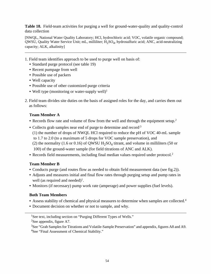
54
Table 18. Field-team activities for purging a well for ground-water-quality and quality-controldata collection
[NWQL, National Water Quality Laboratory; HCl, hydrochloric acid; VOC, volatile organic compound;QWSU, Quality Water Service Unit; mL, milliliter; H2SO4, hydrosulfuric acid; ANC, acid-neutralizingcapacity; ALK, alkalinity]______________________________________________________________________________
1. Field team identifies approach to be used to purge well on basis of:• Standard purge protocol (see table 19)• Recent pumpage from well• Possible use of packers• Well capacity• Possible use of other customized purge criteria
• Well type (monitoring or water-supply well)1
2. Field team divides site duties on the basis of assigned roles for the day, and carries them out as follows:
Team Member A
• Records flow rate and volume of flow from the well and through the equipment setup.2
• Collects grab samples near end of purge to determine and record:3
(1) the number of drops of NWQL HCl required to reduce the pH of VOC 40-mL sample to 1.7 to 2.0 (to a maximum of 5 drops for VOC sample preservation), and(2) the normality (1.6 or 0.16) of QWSU H2SO4 titrant, and volume in milliliters (50 or
100) of the ground-water sample (for field titrations of ANC and ALK).
• Records field measurements, including final median values required under protocol.2
Team Member B• Conducts purge (and routes flow as needed to obtain field measurement data (see fig.2)).• Adjusts and measures initial and final flow rates through purging setup and pump rates in
well (as required and needed)1.• Monitors (if necessary) pump work rate (amperage) and power supplies (fuel levels).
Both Team Members
• Assess stability of chemical and physical measures to determine when samples are collected.4
• Document decision on whether or not to sample, and why.______________________________________________________________________________
1See text, including section on “Purging Different Types of Wells.”2See appendix, figure A7.3See “Grab Samples for Titrations and Volatile-Sample Preservation” and appendix, figures A8 and A9.4See “Final Assessment of Chemical Stability.”
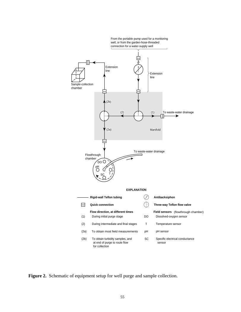
55
Figure 2. Schematic of equipment setup for well purge and sample collection.
Sample-collection chamber
Extension line
(2b)
(2a)
(2) (1) To waste-water drainage
Manifold
To waste-water drainage
SC T
DOpH
Flowthrough chamber
Extension line
From the portable pump used for a monitoring well, or from the garden-hose-threaded connection for a water-supply well
(1) During initial purge stage
(2) During intermediate and final stages
(2a) To obtain most field measurments
(2b) To obtain turbidity samples, and at end of purge to route flow for collection
EXPLANATION
Rigid-wall Teflon tubing
Quick connection
Dissolved-oxygen sensor
Temperature sensor
pH sensor
Specific electrical conductance sensor
DO
T
SC
pH
Antibacksiphon
Three-way Teflon flow valve
Field sensorsFlow direction, at different times (flowthrough chamber)
To obtain most field measurements

56
Despite differences in scientific opinion as to when and how much purging are necessary,and the criteria used to assess when purging is complete, NAWQA field teams will use the stan-dard USGS procedures and criteria for purging and collecting field measurements (table 19). Inapplying the purge protocols, the equipment and procedures used can differ in some respects onthe basis of recent pumping, well capacity, study component, and well type (see below). Withsome exceptions, the same equipment (fig. 2), criteria (table 19), and similar procedures are usedto purge and collect ground-water-quality samples. Deviations from the standard purge proto-cols that are not described below are discussed in advance, if possible, with the NAWQA QASpecialist.
Acceptable deviations from standard purge protocols
Four possible exceptions to the standard purge procedures are recognized and accepted.The first relates to recent pumping. If it can be documented that a volume of water equivalent tothe purge volume already has been pumped from a water-supply or monitoring well within the24-hour period before the field team arrives, sample collection can begin after equipment hasbeen flushed or “conditioned” with ground water and field measurements have been shown to bestable. This effectively reduces the purge time to that needed to achieve stable field measure-ments (table 19, minimally about 15 to 25 minutes).
The second exception to the standard purge protocols relates to well capacity. When thepermeability of the aquifer is low, and a slow recovery limits well capacity, it often is possibleto quickly evacuate the standing water from the well. For a monitoring well, the field team low-ers the pump intake slowly, and evacuates the well at a pump rate that does not suspend sedi-ments. Field measurements and samples are obtained after the water level has recovered to atleast 90 percent of the level measured before evacuation, and provided recovery occurs within24 hours of evacuation.
The third exception to the standard purge protocols also relates to well capacity. Whenpackers have been placed in a well to restrict the zone of water withdrawal, the purge volume isequivalent to three times the volume between the packers. Given that this purge volume couldbe quite small, the field team again could find that only a 15- to 25-minute purge at the low flowrate is needed to remove the necessary water and obtain stable field measurements. As a quality-control measure, pressure transducers, installed above and below the packers, are recommendedto determine that leakage is not occurring across packers or from above or below the zoneisolated for sampling.
The fourth exception to the standard purge protocols is related to the ground-water compo-nent sampled. When purge criteria can be customized for the well and in relation to specific sam-pling objectives, these purge criteria can be used in place of the standard criteria. Thisexception is most appropriate for investigations that focus on a specific, but limited group ofanalytes, such as in a NAWQA Flowpath Study (table 1). In fact, it is recommended that StudyUnits develop and use purging procedures and criteria that best correlate with the concentrationsof analytes being investigated. For example, a customized purge criteria for sampling VOCs isdescribed by Gibs and Imbrigiotta (1990).

57
Table 19. Standard protocols and recommended procedures for conducting and assessingwell purging for the National Water-Quality Assessment Program (modified from F.D. Wilde,U.S. Geological Survey, written commun., 1995--see footnote 1)[Assumes that well capacity is not a limiting factor; see text for further discussion of exceptions.°C, degrees Celsius; %, percent;≤, less than or equal to; >, greater than; <, less than;µS/cm, micro-siemens per centimeter at 25°C; mg/L, milligrams per liter; NTU, nephelometric turbidity units]_____________________________________________________________________________________________
1. Purge a minimum volume of water equal to three times the casing (or wellbore) volume.1
2. Reduce rate of flow from well, if possible, but at least through setup, to no more than about0.1 gallon (~500 milliliters) per minute for 15 to 25 minutes near end of purge (sample-collection rate).2
3. Monitor pH, temperature, specific electrical conductance, and dissolved oxygen through-out the purging process, but particularly during last 15 to 25 minutes. (If trace-elementsamples are being collected, include turbidity measurements as part of monitoring.)
4. The well is considered purged after at least three casing volumes have been removedand values of monitored parameters between 5 successive measurements separated byabout 3- to 5-minute time intervals are within the allowable difference specified below:
Parameter Allowable difference or value pH ± 0.1 units (± 0.05 units if instrument displays
2 or more digits to the right of the decimal)
Temperature ± 0.2°C (thermistor)
Specific electrical conductance (SC) ± 5%, for SC≤ 100µS/cm± 3%, for SC > 100µS/cm
Dissolved oxygen (DO) ± 0.3 mg/L
Turbidity (TU) ± 10%, for TU < 100 NTU: ambient TU is<5NTU for most ground-water systems(visible TU > 5 NTU)
•If measurements appear stable, the median value of the last five measurements for eachparameter (except for pH) is recorded on the appropriate forms (see appendix, figs. A7 and A8),and the field team proceeds with sample collection. For pH, only the last measurement isrecorded.
•If criteria for stability is not achieved, purging is continued until either the field measure-ments stabilize, or the equivalent of five or more wellbore or casing volumes have beenremoved, depending on the judgment of the field team. The field team records the final fieldmeasurements in the manner noted above, and notes any parameters which remain unstable.
•If measurements remain unstable, the field team must decide whether or not to continue withsample collection.
•A lack of stability, indicated by a consistent trend in values upward or downward for pH, SC,DO, and TU, indicates possible problems in well design, or purging setup or technique. It isrecommended that samples not be collected from a well if the setup or technique cannot bealtered to obtain stable measurements.
_____________________________________________________________________________________________1Standing volume is calculated from depth to water and depth of well measurements (see appendix,
fig. A7).2If a high initial rate is used, reduce rate of flow from well and through purge-collection setup to
this rate.

58
Each of the above exceptions actually fulfills the intent of the standard protocols. In eachcase, the procedures and criteria used ensure the removal of stagnant water, and the chemical andphysical stability in flow before samples are collected. In addition, and regardless of what purgecriteria are used, the standard field measurements (DO, SC, T, pH, and, if trace-element samplesare collected, TU) also are determined and documented. They are part of the NAWQA data col-lected at each well (table 1). Thus, except for pH, the median value of the last five stable valuesfor each standard measurement, and any customized purge criterion, are recorded as part of thedata of record. For pH, only the last measurement is recorded.
Purging with different flow rates
With the exception of some Study-Unit Survey Flowpath-Study components (table 1),wells used by NAWQA generally are completed at relatively shallow depths in water-tableaquifers. As a general rule, the purge procedures described above are completed within about2 to 2 1/2 hours, which includes the 15- to 25-minute period at the low flow rate required forsample collection (about 0.1 gal/min or 500 mL).
A low flow rate is required at the end of the purge (and during sample collection) for con-sistency and technical reasons. In combination with a portable, submersible pump, a low flowrate:
(1) is obtainable and maintainable for most, if not all, wells;(2) reflects a discharge that can be sustained at low pump amperage and without surging;(3) reduces the likelihood that sources of ground water entering the well will change (Reilly
and others, 1989);(4) is likely to lead to uniform, or at least less turbulent, flow;(5) reduces the potential for degassing of some constituents, such as VOCs and radon;(6) reduces the likelihood of entraining colloids and other artifacts dislodged and suspended
by turbulence; and(7) provides a rate of flow that is manageable during sample collection.
To achieve some of the above in sampling water-supply wells when the rate of flowthrough the well is high and uncontrollable, part of the flow is diverted (through the equipmentsetup) at the required low rate.
Although use of a higher rate of flow throughout the purge and sample-collection periodthan that required near the end of the purge reduces purge and sample-collection times, it alsoreduces the likelihood that the benefits described above will be achieved. As a compromise thataids in reducing field times, while maintaining some consistency and quality control, higher flowrates (during the initial part of the purge) than the required low flow rate (near the end of thepurge) can be used provided these conditions are met: (1) that the high flow is sustainable, (2)that the high flow is not highly turbulent, (3) that field measurements, including turbidity, whichcould change precipitously at first under the high flow, stabilize relatively quickly, and remainabout the same (no abrupt changes), and (4) that turbidity, in particular, does not remain elevat-ed, but approaches a generally acceptable value (table 19).

59
Purging different types of wells
Perhaps the most substantial differences among wells that the field team could encounterin applying the standard purging protocol (table 19), or one of the acceptable deviations to thatprotocol, occurs in relation to well type (monitoring or water-supply well). Because water-supply wells for NAWQA are chosen on the basis of suitable construction for ground-water-quality data collection (Lapham and others, in press), they are equipped with pumps that can beused to obtain water samples. The location of the well pump intake and the pump rate, however,generally cannot be controlled by the field team. This implies that the field team only has limitedcontrol of some aspects of the purge and sample-collection process at these wells. This is notthe case for most monitoring wells. Because data collection at most monitoring wells selectedby NAWQA will require the use of a portable pump whose intake location and flow rate can bemodified, the field team has considerable control over the purge and sample collection processfor this type of well. Despite the differences in level of control between water-supply and mon-itoring wells, and to promote consistency in purging and data collection from these two types ofwells, it is required that field teams follow the standard procedures (table 19), when possible, orfollow acceptable alternative procedures for purging each type of well. Further guidance onpurging either type of well is provided below.
Water-Supply Wells. Water-supply wells used by NAWQA are selected, in part, becausethey have pumps deemed suitable for producing samples of suitable quality. The field team,however, generally cannot alter the rate at which these pumps operate, nor the location of thepump intake. Generally, the field team only can control the flow rate through their own equip-ment when purging or collecting samples.
To determine the manner in which the purge of a water-supply well is conducted, the fieldteam first estimates the volume of water that will be removed from the well using the ground-water supply-pump rate and the final 15 to 25 minutes of purging (when stability measurementsmust be made). If the estimated volume is about equal to or exceeds the required purge volume,then evacuation of the required purge volume will take only about 15 to 25 minutes. In this case,the field team sets up the equipment and then conducts the purge. This situation commonly aris-es for small water-supply wells, such as those used for single dwellings. Setting the equipmentup first, and then purging this type of well will prevent overpurging, which could adversely af-fect the quality of data obtained by NAWQA for some VOCs (Gibs and Imbrigotta, 1990).
For a water-supply well that requires a purge time considerably longer than 15 to 25 min-utes (for example, more than 2 hours), the field team has the option to request that the well pumpbe turned on before they arrive. This approach commonly is needed for high-capacity wells usedfor irrigation or drinking-water supplies. The field team arrives, however, in time to set upequipment, complete the final 15- to 25-minute phase of purging using the low flow rate throughtheir equipment, and obtain stable field measurements before the required purge volume is evac-uated. If this option is used, the field team also requests that static water-level data be collectedby the pump operator before pumping begins.
As a final consideration in purging a water-supply well, the field team keeps the water-supply pump operating throughout the purge and sample collection. This ensures the removal

60
of standing water from the well, and clears standing water from any plumbing lines leading to thesampling equipment.
To ensure the water-supply well continues to operate, the field team can open more flowvalves than just the one connected to their equipment. This also will reduce the likelihood of back-flow of water stored in plumbing lines that could be connected to the line that transports water tothe sample-collection setup. Backflow often occurs if the plumbing system is not equipped withantibacksiphons. Antibacksiphons generally are absent in secondary distribution lines on low-capacity supply wells, such as those used by rural homeowners for local supplies.
Since water-supply pumps operate continuously during the purge and sample collection,there is a chance that the supply pump could burn out. Although most commercial pumps are de-signed to operate for hours without problems, old, worn pumps are a potential problem. If a pumpburns out, the field team generally should expect to replace it upon the owner’s request. To limitthe chance of pump burnout, the field team needs to work quickly and efficiently to keep the totalpumping time required to purge and sample as short as possible. If this is achieved by using a highflow rate, through setup equipment, this flow rate is reduced to about 0.1 gal (500 mL) per minuteduring the final stage of the purge and during sample collection.
Monitoring Wells . Because the field team supplies the pump, they control the rate at whichwater is pumped from the well and through their equipment, as well as the location of the pumpintake in the well. During the purge of a monitoring well, it is important to recognize that pumpintake rate, emplacement, and location can influence the quality of the water obtained. Thus, it isimportant that these pumps be used in a consistent manner for the purge and sample collection atdifferent monitoring wells.
As in the case of a water-supply well, the first step in applying the purge protocol to a mon-itoring well is to determine if the required purge volume can be evacuated in the 15 to 25 minutesneeded for field measurements at the required low-flow rate for sample collection. For this 15- to25-minute period, and a rate of about 0.1 gal (500 mL) per minute, about 1.5-2.5 gal (7-11 L) willbe evacuated from the well. If the required purge volume is less than or equal to this volume, thefield team sets up all equipment and then purges the well at this low rate. If the required purgevolume exceeds about 1.5-2.5 gal, the field team can purge the well at an initially high, but accept-able, flow rate (as described earlier) to reduce the purge time, and then reduce the flow rate to thesample-collection rate for the final 15 to 25 minutes of the purge, and take and document final fieldmeasurements.
Pump intake emplacement is a consideration in the purge of a monitoring well. To reducethe suspension of sediments in the well, the pump intake always is lowered slowly into the well.Initially, the intake is placed just below the surface of the water standing in the well.
With the setup equipment properly configured to route flow directly to waste (fig. 2), thepump is turned on at an initially low rate to avoid sediment suspension in the well. If the requiredpurge volume is small, and the entire purge can be conducted within 2 hours at the low rate re-quired for final field measurements and sample collection, the pump rate is slowly adjusted to arate of about 0.1 gal (500 mL) per minute. This rate is verified by measuring the outflow from thewaste line, and recorded (appendix, fig. A7).

61
If the required purge volume is high, and an initially high pump rate is desired, the pumprate is slowly increased until either the maximum acceptable flow (as described earlier) or pump-ing capacity is reached (because of pump limitations or well capacity). In general, unless thewell capacity is extremely low and purging cannot be completed within 2 to 2 1/2 hours, rapidevacuation of the standing water in the well is avoided. As noted earlier, the initial flow rate ismeasured at the waste-line outflow and recorded (appendix, fig. A7).
After the initial flow rate has been measured, the flow is rerouted through the instrumentedflowthrough chamber (fig. 2) and the purge continues. Field measurements are made and record-ed from this point on (appendix, fig. A7).
As the purge continues, and to enhance the evacuation of all standing water, the pump in-take in unpacked wells is lowered slowly until it resides a distance above the open (perforated,or screened) interval that is equal to 7 to 10 times the diameter of the well casing (borehole).Assuming the monitoring well was designed correctly with a short open interval of 2 to 10 ft(Lapham and others, in press), this final location of the intake aids in promoting the flow of waterfrom the entire screened interval to the pump intake.
Any substantial changes in pump intake location (lift) could affect the flow rate. Thus, allchanges in pump intake location are completed before the final 15- to 25-minute stage of thepurge. At this time, any high pump intake rate is reduced to about 0.1 gal (500 mL) per minute,and the last five sets of successive field measurements are taken, while the last of the requiredpurge volume is evacuated from the monitoring well.
Grab samples for titrations and volatile-sample preservation
During the final 15 to 25 minutes of the purge, or whenever measurements appear stablein relation to the purge criteria (table 19), two grab samples are taken. The first is a 100-mLsample which, if the pH exceeds 4.5, is quickly titrated to roughly determine the acid neutraliz-ing capacity (ANC) of the sample (Radtke and Wilde, in press). From the ANC value, the fieldteam determines the optimum sample volumes and titrant normality (1.6N or 0.16N sulfuricacid) to be used for subsequent, quantitative field titrations (table 20). If the sample pH is 4.5or less, no field titrations for ANC or alkalinity are required.
If VOC samples are scheduled for collection at the well, a second 40-mL grab sample isobtained in a clean glass beaker to determine the amount of NWQL hydrochloric acid needed topreserve VOC samples (from March 31, 1993 to January 31, 1994, samples were preserved withNWQL-concentrated hydrochloric acid). The acid is added drop by drop to this beaker, the sam-ple is stirred or mixed, and the pH is measured after each acid addition until it is between 1.7 and2.0. The number of drops of NWQL acid used must be recorded on field forms (appendix, figs.A8, A10-A, A11-A, A12-A, and A13-A). To avoid damage to NWQL instruments, however,no more than 5 drops of NWQL hydrochloric acid are to be added to a VOC sample (BruceDarnel, VOC National Synthesis Team, U.S. Geological Survey, written commun., 1995).

62
Table 20. Field-titration procedures for ground-water samples of the National Water-QualityAssessment Program[mg/L, milligrams per liter; mL, milliliters]______________________________________________________________________________
• Except when replicate titrations are scheduled at selected wells, one filtered, and(optionally) one unfiltered, sample will be titrated at each site.1
• The unfiltered sample is titrated for acid-neutralizing capacity (ANC, mg/L2). The filteredsample is titrated for alkalinity (ALK, as mg/L CaCO3; carbonate, as mg/L CO3
–2,
bicarbonate, as mg/L HCO3–; and hydroxide, as mg/L OH–).
• Conducted in the field on fresh samples by the incremental addition of titrant, generallywith digital equipment, and the recommended volume of sample and normality of titrant,as follows:
Parameter(s) Expected Value Sample Volume Titrant Normality
ANC or ALK 0.0-50 mg/L as CaCO3 100 mL 0.16
ANC or ALK 50-200 mg/L as CaCO3 50 mL 0.16
ANC or ALK 200-1,000 mg/L as CaCO3 100 mL 1.6
ANC or ALK Exceeds 1,000 mg/L as CaCO3 50 mL 1.6
• Estimates of ANC, ALK, and contributing species are determined by the Inflection-PointMethod (Radtke and Wilde, in press). Inflection points to determine ANC or ALK andcontributing species are near pH values of about 8.2 and 4.5 for most waters buffered bythe carbonate system.
• If difficulties arise in determining titration endpoints--which could be encountered for saline,low-conductivity, low-alkalinity, anoxic, or organic-rich ground waters--the Gran-FunctionPlot Method is recommended (Radtke and Wilde, in press).
• Field titration data are recorded (appendix, fig. A9) and later stored electronically underthe appropriate parameter codes in NWIS-I QWDATA (for primary ground-water samples)or NWIS-I QADATA (for replicate ground-water samples).
______________________________________________________________________________1Before 1996, titration of an unfiltered sample was required and titration of a filtered sample was
optional.2Reporting values above assigns carbonate chemical species as the primary sources of neutralizing
capacity. At this writing, appropriate parameter codes are not available to enter data above in NWIS-Iin milliequivalent units.

63
Final assessment of chemical stability
The field team decides whether or not to collect ground-water-quality samples on the basisof the relative stability of field measurements taken near the end of the purge, as the last of therequired purge volume is evacuated from the well (table 19). It is recommended that samplesnot be collected if unstable field measurements persist. Unstable measurements generally indi-cate one or more of the following is true: (1) that the source of water entering the well is changingwith time, (2) that a decreasing proportion of water leaving the well is water that initially wasstanding in the well, or (3) that water is entering the well in a disproportionate manner as timeelapses from a new source or from several sources. Thus, the resulting water-quality data ob-tained from sampling a well with unstable field measurements may or may not relate to the landuse, aquifer, or other conditions being investigated.
Sample Collection and Processing
Sample collection begins when purge criteria have been met. The type and number of in-dividual ground-water-quality and QC samples obtained, however, depend on the ground-watercomponent (Study Unit Survey, Land-Use Study, or Flowpath Study) for which samples arebeing collected (table 1). Study-Unit (or Subunit) Surveys and Land-Use Studies commonlyinclude the collection of samples for organic, inorganic, and possibly trace-element, radio-chemical, and isotopic analyses. Flowpath Studies generally are limited in scope and requirefewer samples than either Surveys or Land-Use Studies. For each component, routine, andpossibly topical, quality-control samples also are scheduled for collection at selected wells.
Regardless of the particular component under investigation, protocols and procedures arefollowed in a consistent, timely, efficient, and quality-controlled manner. The protocols andprocedures that follow describe the sample-collection methods to be used for NAWQA ground-water-quality studies (table 21), and include the collection and processing (filtration, preserva-tion, handling, and shipment) of water-quality and QC samples for a given analysis. In addition,the protocols also specify an order or sequence in which groups of samples for different analytesare collected under these protocols, which generally is to be similar at each well in a given com-ponent, and among components with similar data-collection requirements.
Overall, the NAWQA sample-collection protocols and recommended procedures (table21) follow USGS protocols and procedures (F.D. Wilde, U.S. Geological Survey, writtencommun., 1995--see footnote 1). Thus, samples for organic analytes (unfiltered, then filtered)are collected first, followed by samples for inorganic analytes (filtered, then unfiltered), whichin turn are followed by the collection of samples for other (ancillary) analytes--isotopes, radio-chemicals, and chlorofluorocarbons (table 21). Routine replicate ground-water-quality samples,including those for field spikes, are collected in conjunction with the primary ground-water-quality samples (table 21). (Routine QC samples that use blank water are collected in thefield after ground-water-quality samples and after the decontamination of sample-collectionequipment.)
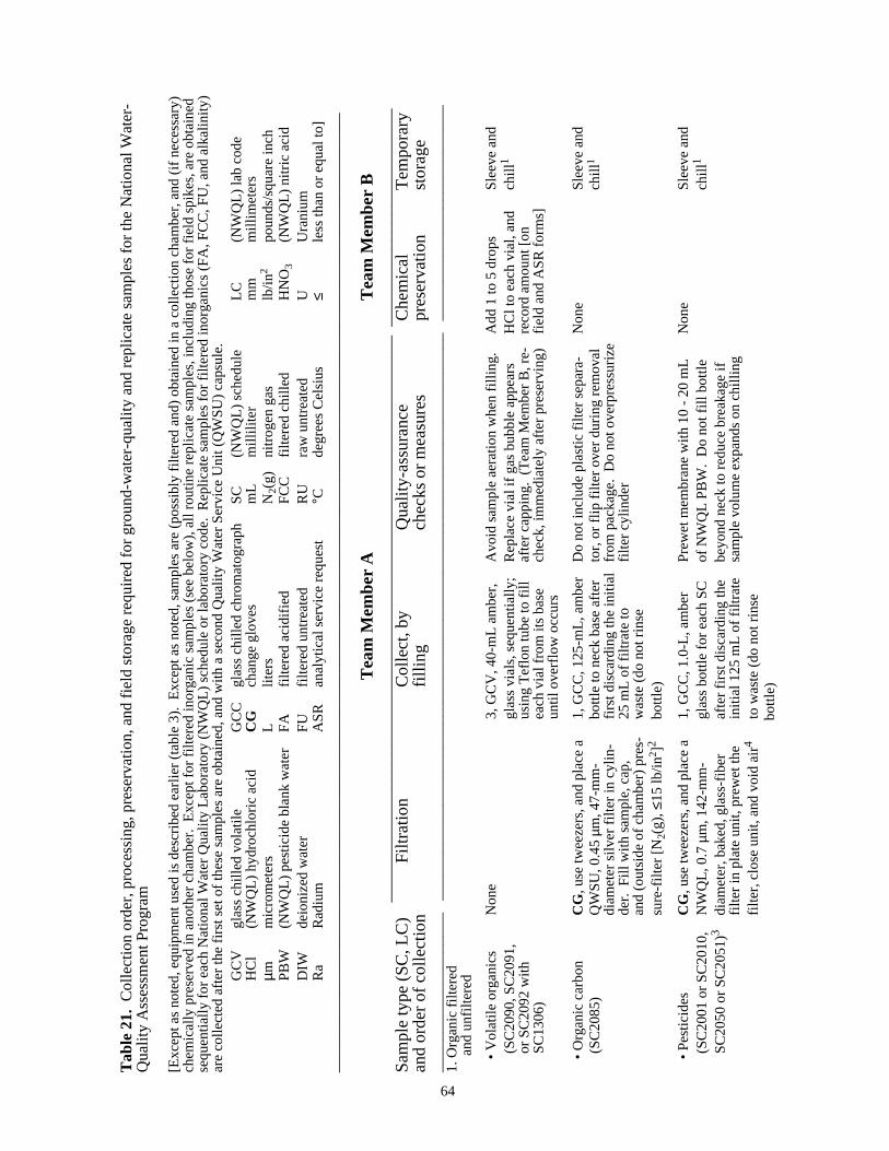
Tab
le 2
1. C
olle
ctio
n or
der,
pro
cess
ing,
pre
serv
atio
n, a
nd fi
eld
stor
age
requ
ired
for
grou
nd-w
ater
-qua
lity
and
repl
icat
e sa
mpl
es fo
r th
e N
atio
nal W
ater
-Q
ualit
y A
sses
smen
t Pro
gram
[Exc
ept a
s no
ted,
equ
ipm
ent u
sed
is d
escr
ibed
ear
lier
(tab
le 3
). E
xcep
t as
note
d, s
ampl
es a
re (
poss
ibly
filte
red
and)
obt
aine
d in
a c
olle
ctio
n ch
ambe
r, a
nd (
if ne
cess
ary)
chem
ical
ly p
rese
rved
in a
noth
er c
ham
ber.
Exc
ept f
or fi
ltere
d in
orga
nic
sam
ples
(se
e be
low
), a
ll ro
utin
e re
plic
ate
sam
ples
, inc
ludi
ng th
ose
for
field
spi
kes,
are
obt
aine
dse
quen
tially
for
each
Nat
iona
l Wat
er Q
ualit
y La
bora
tory
(N
WQ
L) s
ched
ule
or la
bora
tory
cod
e. R
eplic
ate
sam
ples
for
filte
red
inor
gani
cs (
FA
, FC
C, F
U, a
nd a
lkal
inity
)ar
e co
llect
ed a
fter
the
first
set
of t
hese
sam
ples
are
obt
aine
d, a
nd w
ith a
sec
ond
Qua
lity
Wat
er S
ervi
ce U
nit (
QW
SU
) ca
psul
e.G
CV
glas
s ch
illed
vol
atile
GC
Cgl
ass
chill
ed c
hrom
atog
raph
SC
(NW
QL)
sch
edul
eLC
(NW
QL)
lab
code
HC
l(N
WQ
L) h
ydro
chlo
ric a
cid
CG
chan
ge g
love
sm
Lm
illili
ter
mm
mill
imet
ers
µmm
icro
met
ers
Llit
ers
N 2(g)
nitr
ogen
gas
lb/in2
poun
ds/s
quar
e in
chP
BW
(NW
QL)
pes
ticid
e bl
ank
wat
erF
Afil
tere
d ac
idifi
edF
CC
filte
red
chill
edH
NO
3(N
WQ
L) n
itric
aci
dD
IWde
ioni
zed
wat
erF
Ufil
tere
d un
trea
ted
RU
raw
unt
reat
edU
Ura
nium
Ra
Rad
ium
AS
Ran
alyt
ical
ser
vice
req
uest
°Cde
gree
s C
elsi
us≤
less
than
or
equa
l to]
____
____
____
____
____
____
____
____
____
____
____
____
____
____
____
____
____
____
____
____
____
____
____
____
____
____
____
____
____
____
Tea
m M
embe
r A
Tea
m M
embe
r B
__
____
____
____
____
____
____
____
____
____
____
____
____
____
____
____
___
___
____
____
____
____
____
__S
ampl
e ty
pe (
SC
, LC
)F
iltra
tion
Col
lect
, by
Qua
lity-
assu
ranc
eC
hem
ical
Tem
pora
ryan
d or
der
of c
olle
ctio
nfil
ling
chec
ks o
r m
easu
res
pres
erva
tion
stor
age
____
____
____
____
____
__
____
____
____
____
____
____
____
____
____
____
____
____
____
____
____
____
____
_ _
____
____
____
____
____
____
__1.
Org
anic
filte
red
and
unf
ilter
ed
• V
olat
ile o
rgan
ics
Non
e3,
GC
V, 4
0-m
L am
ber,
Avo
id s
ampl
e ae
ratio
n w
hen
fillin
g.A
dd 1
to 5
dro
psS
leev
e an
d(S
C20
90, S
C20
91,
glas
s vi
als,
seq
uent
ially
;R
epla
ce v
ial i
f gas
bub
ble
appe
ars
HC
l to
each
via
l, an
dch
ill1
or S
C20
92 w
ithus
ing
Tef
lon
tube
to fi
llaf
ter
capp
ing.
(T
eam
Mem
ber
B, r
e-re
cord
am
ount
[on
SC
1306
)ea
ch v
ial f
rom
its
base
chec
k, im
med
iate
ly a
fter
pres
ervi
ng)
field
and
AS
R fo
rms]
until
ove
rflo
w o
ccur
s
• O
rgan
ic c
arbo
nC
G, u
se tw
eeze
rs, a
nd p
lace
a1,
GC
C, 1
25-m
L, a
mbe
rD
o no
t inc
lude
pla
stic
filte
r se
para
-N
one
Sle
eve
and
(SC
2085
)Q
WS
U, 0
.45µm
, 47-
mm
-bo
ttle
to n
eck
base
afte
rto
r, o
r fli
p fil
ter
over
dur
ing
rem
oval
chill
1
diam
eter
silv
er fi
lter
in c
ylin
-fir
st d
isca
rdin
g th
e in
itial
from
pac
kage
. D
o no
t ove
rpre
ssur
ize
der.
Fill
with
sam
ple,
cap
,25
mL
of fi
ltrat
e to
filte
r cy
linde
ran
d (o
utsi
de o
f cha
mbe
r) p
res-
was
te (
do n
ot r
inse
sure
-filt
er [N
2(g)
,≤15
lb/in
2 ]2
bottl
e)
• P
estic
ides
CG
, use
twee
zers
, and
pla
ce a
1, G
CC
, 1.0
-L, a
mbe
rP
rew
et m
embr
ane
with
10
- 20
mL
Non
eS
leev
e an
d(S
C20
01 o
r S
C20
10,
NW
QL,
0.7µm
, 142
-mm
-gl
ass
bottl
e fo
r ea
ch S
Cof
NW
QL
PB
W.
Do
not f
ill b
ottle
chill
1
SC
2050
or
SC
2051
)3
diam
eter
, bak
ed, g
lass
-fib
eraf
ter
first
dis
card
ing
the
beyo
nd n
eck
to r
educ
e br
eaka
ge if
filte
r in
pla
te u
nit,
prew
et th
ein
itial
125
mL
of fi
ltrat
esa
mpl
e vo
lum
e ex
pand
s on
chi
lling
filte
r, c
lose
uni
t, an
d vo
id a
ir4to
was
te (
do n
ot r
inse
bottl
e)
64
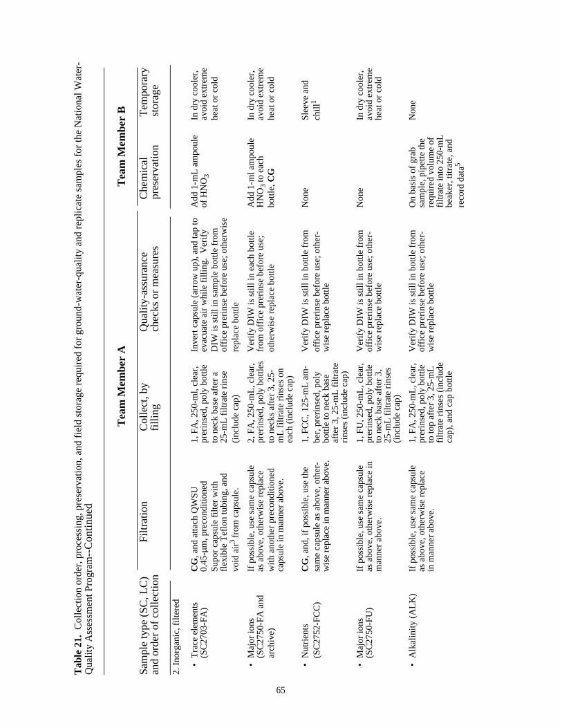
Tab
le 2
1. C
olle
ctio
n or
der,
pro
cess
ing,
pre
serv
atio
n, a
nd fi
eld
stor
age
requ
ired
for
grou
nd-w
ater
-qua
lity
and
repl
icat
e sa
mpl
es fo
r th
e N
atio
nal W
ater
-Q
ualit
y A
sses
smen
t Pro
gram --
Con
tinue
d__
____
____
____
____
____
____
____
____
____
____
____
____
____
____
____
____
____
____
____
____
____
____
____
____
____
____
____
Tea
m M
embe
r A
Tea
m M
embe
r B
___
____
____
____
____
____
____
____
____
____
____
____
____
____
____
____
__ _
____
____
____
____
____
____
Sam
ple
type
(S
C, L
C)
Filt
ratio
nC
olle
ct, b
yQ
ualit
y-as
sura
nce
Che
mic
alT
empo
rary
and
orde
r of
col
lect
ion
fillin
gch
ecks
or
mea
sure
spr
eser
vatio
nst
orag
e__
____
____
____
___
__
____
____
____
____
____
____
____
____
____
____
____
____
____
____
____
__
____
____
____
____
____
____
__2.
Inor
gani
c, fi
ltere
d
•T
race
ele
men
tsC
G, a
nd a
ttach
QW
SU
1, F
A, 2
50-m
l, cl
ear,
Inve
rt c
apsu
le (
arro
w u
p), a
nd ta
p to
Add
1-m
L am
poul
eIn
dry
coo
ler,
(SC
2703
-FA
)0.
45-µm
, pre
cond
ition
edpr
erin
sed,
pol
y bo
ttle
evac
uate
air
whi
le fi
lling
. V
erify
of H
NO
3av
oid
extr
eme
Sup
or c
apsu
le fi
lter
with
to n
eck
base
afte
r a
DIW
is s
till i
n sa
mpl
e bo
ttle
from
heat
or
cold
flexi
ble
Tef
lon
tubi
ng, a
nd25
-mL
filtr
ate
rinse
offic
e pr
erin
se b
efor
e us
e; o
ther
wis
evo
id a
ir3fr
om c
apsu
le.
(incl
ude
cap)
repl
ace
bottl
e
•M
ajor
ions
If po
ssib
le, u
se s
ame
caps
ule
2, F
A, 2
50-m
L, c
lear
,V
erify
DIW
is s
till i
n ea
ch b
ottle
Add
1-m
l am
poul
eIn
dry
coo
ler,
(SC
2750
-FA
and
as a
bove
, oth
erw
ise
repl
ace
prer
inse
d, p
oly
bottl
esfr
om o
ffice
pre
rinse
bef
ore
use;
HN
O3
to e
ach
avoi
d ex
trem
ear
chiv
e)w
ith a
noth
er p
reco
nditi
oned
to n
ecks
afte
r 3,
25-
othe
rwis
e re
plac
e bo
ttle
bottl
e,C
Ghe
at o
r co
ldca
psul
e in
man
ner
abov
e.m
L fil
trat
e rin
ses
onea
ch (
incl
ude
cap)
•N
utrie
nts
CG
, and
, if p
ossi
ble,
use
the
1, F
CC
, 125
-mL
am-
Ver
ify D
IW is
stil
l in
bottl
e fr
omN
one
Sle
eve
and
(SC
2752
-FC
C)
sam
e ca
psul
e as
abo
ve, o
ther
-be
r, p
rerin
sed,
pol
yof
fice
prer
inse
bef
ore
use;
oth
er-
chill
1
wis
e re
plac
e in
man
ner
abov
e.bo
ttle
to n
eck
base
wis
e re
plac
e bo
ttle
afte
r 3,
25-
mL
filtr
ate
rinse
s (in
clud
e ca
p)
•M
ajor
ions
If po
ssib
le, u
se s
ame
caps
ule
1, F
U, 2
50-m
L, c
lear
,V
erify
DIW
is s
till i
n bo
ttle
from
Non
eIn
dry
coo
ler,
(SC
2750
-FU
)as
abo
ve, o
ther
wis
e re
plac
e in
prer
inse
d, p
oly
bottl
eof
fice
prer
inse
bef
ore
use;
oth
er-
avoi
d ex
trem
em
anne
r ab
ove.
to n
eck
base
afte
r 3,
wis
e re
plac
e bo
ttle
heat
or
cold
25-m
L fil
trat
e rin
ses
(incl
ude
cap)
•A
lkal
inity
(A
LK)
If po
ssib
le, u
se s
ame
caps
ule
1, F
A, 2
50-m
L, c
lear
,V
erify
DIW
is s
till i
n bo
ttle
from
On
basi
s of
gra
bN
one
as a
bove
, oth
erw
ise
repl
ace
prer
inse
d, p
oly
bottl
eof
fice
prer
inse
bef
ore
use;
oth
er-
sam
ple,
pip
ette
the
in m
anne
r ab
ove.
to to
p af
ter
3, 2
5-m
Lw
ise
repl
ace
bottl
ere
quire
d vo
lum
e of
filtr
ate
rinse
s (in
clud
efil
trat
e in
to 2
50-m
Lca
p), a
nd c
ap b
ottle
beak
er, t
itrat
e, a
ndre
cord
dat
a5
65

Tab
le 2
1. C
olle
ctio
n or
der,
pro
cess
ing,
pre
serv
atio
n, a
nd fi
eld
stor
age
requ
ired
for
grou
nd-w
ater
-qua
lity
and
repl
icat
e sa
mpl
es fo
r th
e N
atio
nal W
ater
-Q
ualit
y A
sses
smen
t Pro
gram --
Con
tinue
d__
____
____
____
____
____
____
____
____
____
____
____
____
____
____
____
____
____
____
____
____
____
____
____
____
____
____
____
__
Tea
m M
embe
r A
Tea
m M
embe
r B
___
____
____
____
____
____
____
____
____
____
____
____
____
____
____
____
__ _
____
____
____
____
____
____
___
Sam
ple
type
(S
C, L
C)
Filt
ratio
nC
olle
ct, b
yQ
ualit
y-as
sura
nce
Che
mic
alT
empo
rary
and
orde
r of
col
lect
ion
fillin
gch
ecks
or
mea
sure
spr
eser
vatio
nst
orag
e__
____
____
____
___
___
____
____
____
____
____
____
____
____
____
____
____
____
____
____
____
__
____
____
____
____
____
____
___
2. In
orga
nic
unfil
tere
d
•M
ajor
ions
Non
e1,
RU
, 500
-ml,
clea
r, p
rerin
sed
Ver
ify D
IW is
stil
l in
bottl
e fr
omN
one
In d
ry c
oole
r,(S
C27
50-R
U)
poly
bot
tle to
nec
k ba
se a
fter
3of
fice
prer
inse
bef
ore
use;
oth
er-
avoi
d ex
trem
e25
-mL
rinse
s w
ith r
aw s
ampl
ew
ise
repl
ace
bottl
ehe
at o
r co
ld.
(incl
ude
cap)
•A
cid-
neut
raliz
atio
nN
one
1, F
A, 2
50-m
L, c
lear
, pre
rinse
dV
erify
DIW
is s
till i
n bo
ttle
from
On
basi
s of
gra
bN
one
capa
city
(A
NC
),po
ly b
ottle
to to
p af
ter
3, 2
5-of
fice
prer
inse
bef
ore
use;
oth
er-
sam
ple,
pip
ette
the
reco
mm
ende
dm
L rin
ses
with
raw
sam
ple
wis
e re
plac
e bo
ttle
requ
ired
volu
me
(incl
ude
cap)
into
a c
lean
, 250
-mL
beak
er, t
itrat
e, a
ndre
cord
dat
a5
3. O
ther
Sam
ples
•T
race
ele
men
tsC
G, a
nd a
ttach
pre
con-
1, F
A, 1
-L, c
lear
, pre
rinse
d,V
erify
DIW
is s
till i
n bo
ttle
from
CG
, and
add
2 H
NO 3
In d
ry c
oole
r,(1
.0-L
sam
ples
, for
ditio
ned
caps
ule
in m
an-
poly
bot
tle to
nec
k ba
se fo
rof
fice
prer
inse
bef
ore
use,
oth
er-
ampo
ules
to e
ach
avoi
d ex
trem
eex
ampl
e, U
, and
Ra)
ner
sim
ilar
to th
at u
sed
each
ele
men
t afte
r a
25-m
Lw
ise
repl
ace
bottl
ebo
ttle
heat
or
cold
.fo
r S
C27
03 a
bove3
rinse
of b
ottle
and
cap
•T
ritiu
m is
otop
esN
one
1, 1
.0-L
, cle
ar, p
rerin
sed
poly
Ver
ify D
IW is
stil
l in
bottl
e fr
omN
one
In d
ry c
oole
r,bo
ttle,
fille
d to
top
afte
r 3,
offic
e pr
erin
se b
efor
e us
e, o
ther
-av
oid
extr
eme
25-m
L rin
ses
(incl
ude
cap
wis
e re
plac
e bo
ttle.
Lea
ve n
oco
ld o
r he
at.
with
con
ical
inse
rt)
head
spac
e in
bot
tle
•D
eute
rium
-Oxy
gen
Non
e1,
125
-ml,
glas
s, a
mbe
rLe
ave
no h
eads
pace
in b
ottle
Non
eIn
dry
coo
ler,
isot
opes
bottl
e to
top
afte
r 3,
25-
ml
avoi
d ex
trem
erin
ses
(incl
ude
cap
with
heat
or
cold
.co
nica
l ins
ert)
66
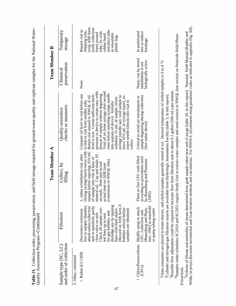
Tab
le 2
1. C
olle
ctio
n or
der,
pro
cess
ing,
pre
serv
atio
n, a
nd fi
eld
stor
age
requ
ired
for
grou
nd-w
ater
-qua
lity
and
repl
icat
e sa
mpl
es fo
r th
e N
atio
nal W
ater
-Q
ualit
y A
sses
smen
t Pro
gram --
Con
tinue
d__
____
____
____
____
____
____
____
____
____
____
____
____
____
____
____
____
____
____
____
____
____
____
____
____
____
____
____
__
Tea
m M
embe
r A
Tea
m M
embe
r B
___
____
____
____
____
____
____
____
____
____
____
____
____
____
____
____
__
____
____
____
____
____
____
___
Sam
ple
type
(S
C, L
C)
Filt
ratio
nC
olle
ct, b
yQ
ualit
y-as
sura
nce
Che
mic
alT
empo
rary
and
orde
r of
col
lect
ion
fillin
gch
ecks
or
mea
sure
spr
eser
vatio
nst
orag
e__
____
____
____
__
___
____
____
____
____
____
____
____
____
____
____
____
____
____
____
____
__
____
____
____
____
____
____
____
3. O
ther
, con
tinue
d
•R
adon
(LC
1369
)D
isco
nnec
t ext
ensi
on1,
rad
on s
cint
illat
ion
vial
, afte
rC
ompa
re o
il le
vel i
n vi
al b
efor
e us
eN
one
Rep
ack
vial
inlin
e to
sam
ple
cham
ber,
rinsi
ng s
yrin
ge b
arre
l tw
ice
with
to th
at in
via
l fro
m a
noth
er tu
be.
ship
ping
tube
,at
tach
rad
on-c
olle
ctio
nsa
mpl
e be
fore
inje
ctin
g 10
.0 m
L R
etur
n vi
al u
nuse
d to
NW
QL
if oi
lw
rap
AS
R fo
rmun
it to
man
ifold
, par
tlyof
sam
ple
into
via
l at b
ase
ofle
vel i
s lo
w.
Cre
ate
suffi
cien
t bac
k-(w
ith c
olle
ctio
ncl
ose
valv
e on
uni
t.m
iner
al o
il. C
ap a
nd s
hake
10
pres
sure
in d
evic
e to
cre
ate
easy
with
-tim
e) a
roun
dC
heck
all
sam
ple-
wet
-se
cond
s. N
ote
and
reco
rddr
awal
of s
ampl
e w
ithou
t deg
assi
ng.
tube
, fix
with
ted
lines
up
to u
nit
actu
al ti
me
on A
SR
form
Voi
d al
l air
from
syr
inge
afte
r se
cond
rubb
er b
and,
for
gas
bubb
les,
and
(com
men
ts-t
o-N
WQ
L lin
e)rin
se b
efor
e in
sert
ing
syrin
ge n
eedl
ean
d pl
ace
tube
disl
odge
any
by
tapp
ing
into
sep
tum
of d
evic
e. I
nitia
llyin
res
eala
ble
lines
with
har
d ob
ject
.w
ithdr
aw 1
5 m
L of
sam
ple,
inve
rtpl
astic
bag
.(R
ecor
d on
AS
R fo
rm if
syrin
ge [n
eedl
e up
], vo
id s
ampl
e to
bubb
les
refo
rm b
efor
ele
ave
10.0
mL
in s
yrin
ge b
arre
l, re
-sa
mpl
es a
re o
btai
ned)
inse
rt n
eedl
e (d
own)
into
via
l to
colle
ct
• C
hlor
oflu
oroc
arbo
nsM
odify
set
up to
atta
chT
hree
to fi
ve C
FC
via
ls fi
lled
Crit
ical
to a
void
air
entr
ainm
ent o
rN
one;
can
be
stor
edIn
par
titio
ned
(C
FC
s)C
FC
--co
llect
ion
unit
acco
rdin
g to
pro
cedu
res
used
sam
ple
dega
ssin
g du
ring
colle
ctio
nin
defin
itely
if n
otbo
x to
red
uce
(Bus
enbe
rg a
nd P
lum
-by
Bus
enbe
rg a
nd P
lum
mer
(See
rad
on a
bove
)bi
olog
ical
ly a
ctiv
ebr
eaka
gem
er, 1
992)
to m
anifo
ld(1
992)
or p
ump
tubi
ng o
utle
t__
____
____
____
____
____
____
____
____
____
____
____
____
____
____
____
____
____
____
____
____
____
____
____
____
____
____
____
____
____
____
____
____
___
1 Gla
ss c
onta
iner
s ar
e pl
aced
in fo
am s
leev
es, a
nd c
hille
d sa
mpl
es g
ener
ally
sto
red
in ic
e. D
esire
d te
mpe
ratu
re o
f chi
lled
sam
ples
is 0
to 4
°C2 C
ylin
der
and
nitr
ogen
-gas
filtr
atio
n sy
stem
are
ava
ilabl
e fr
om H
ydro
logi
c In
stru
men
ts F
acili
ty (
tabl
e 3,
in th
is r
epor
t).
3 Pos
sibl
e flo
w a
djus
tmen
t cou
ld b
e re
quire
d to
incr
ease
flow
from
filtr
atio
n un
it to
abo
ut 0
.1 g
allo
n (5
00 m
L) p
er m
inut
e.4 S
ampl
es u
nder
sch
edul
es S
C20
10 a
nd S
C20
51 r
equi
re S
tudy
Uni
t to
extr
act w
ater
sam
ples
and
sen
d ex
trac
ts to
NW
QL
(see
sec
tion
on P
estic
ide
Sol
id-P
hase
Ext
ract
ion)
.5 V
olum
e of
filtr
ate
and
norm
ality
of t
itran
t det
erm
ined
from
gra
b sa
mpl
e ta
ken
near
end
of p
urge
(ta
ble
20, i
n th
is r
epor
t).
Nat
iona
l F
ield
Man
ual (
Rad
tke
and
Wild
e, in
pre
ss)
disc
usse
s in
crem
enta
l and
Gra
n tit
ratio
n m
etho
ds a
nd c
alcu
latio
ns.
For
NW
IS-I
, rec
omm
end
usin
g pa
ram
eter
cod
es a
s in
dica
ted
in a
ppen
dix
(fig
. A8)
.
67

68
Field-team functions
The setup (fig. 2) used to purge the well is modified slightly for sample collection. Theshort turbidity-collection line is replaced by an extension line that runs to the sample-collectionchamber. The flow, which has been passing through an instrumented flowthrough chamber, isrerouted (for example, using the second three-way flow valve as shown in fig. 2) through thisextension line that is connected to the sample-collection chamber. The rate of flow through thesample-collection setup is about 0.1 gal (500 mL) per minute.
In general, samples are obtained and, with one or two exceptions, processed (for example,filtered) byTeam Member A (table 21). Except for radon and chlorofluorocarbons, which re-quire special collection equipment, and dissolved organic carbon, which requires a pressurizedfiltration, samples are obtained (sample containers are opened, if necessary, final rinsed, filled,and closed) only within the collection chamber. As each sample container is removed from thechamber, it is set aside on a clean surface, and not handed directly toTeam Member B. Thisreduces the likelihood of contamination ofTeam Member A, the chamber, and subsequent sam-ples, as collection continues.
In general,Team Member B, who has removed coveralls and work gloves, preserves (ifnecessary) and temporarily stores samples (table 21).Team Member B also performs fieldtitrations.
Chemical preservation of NAWQA samples currently (1995) requires a single preservationchamber (for NWQL hydrochloric and nitric acids). This chamber is separate from that used tocollect samples (table 3). During preservation, samples are opened, preserved, and closed in thischamber byTeam Member B.
Throughout the collection process, the field-team members frequently replace their glovesat logical intervals to further reduce sample contamination (table 21, CG). If either one leavesthe collection or preservation areas to perform other tasks, gloves must be replaced before activ-ities in these areas are resumed.
Near the end of the sample-collection process, field titrations (particularly when replicatefiltered (ALK) or unfiltered (ANC) samples are taken) generally will require most ofTeamMember B’s time. Therefore,Team Member A often will complete the collection of all sam-ples after that for ANC with little or no assistance (table 21).
Special considerations for selected sample types
With adequate training and preparation, collection procedures for most sample types re-quire no more than a conscientious effort to rinse and fill a bottle in a clean setting to obtain high-quality data. Situations arise, however, which necessitate processing samples simultaneouslywith their collection, or which require modifications to the general field-equipment setup andprotocols described (table 21).
Filtered Samples. To obtain high-quality samples, care must be taken in the use of filterunits and to avoid overpressurizing these units. The NWQL aluminum plate filter (for pesticide

69
samples) is prepared in the collection chamber (table 21) and has a simple nipple fitting, whichis connected to the sample outflow orifice inside the sample chamber by a short piece of Teflontube. Air is evacuated from the plate unit using the trip valve on top of the unit as it is filled byraw sample flow. After evacuating the air, the trip valve is closed. Initially, some filtrate is dis-carded before any samples are collected (table 21).
The sample for dissolved (filtered) organic carbon (DOC) is collected directly in the DOCfilter cylinder in the collecting chamber. The DOC cylinder subsequently is capped, removedfrom the chamber, and the sample filtered under N2 gas at a low (15 lbs/in2 or less) internal pres-sure. (Pressures in excess of 15 lbs/in2 can be hazardous and can rupture the filter membrane andinvalidate the sample.)
Routine NAWQA 0.45-µm-filtered inorganic samples are obtained using the QWSU cap-sule filter (for inorganic samples). The capsule is preconditioned before use (see “Final Pre-sampling Plans and Preparations”). The capsule nipples are attached to flexible Teflon lines,which allow the capsule to be inverted (arrow on capsule denotes direction of flow) during itsfinal rinse and use. Inverting the capsule so that the flow is vertically upward while the capsuleinitially fills with water, combined with tapping the side of the capsule several times while it fills,forces most air out of the capsule. Purging most of the air from the capsule filter helps preventoxidation and possible precipitation of redox-sensitive analytes (for example, iron, manganese,aluminum, and uranium) that would (negatively) bias filtrate concentrations. Procedures for fil-tering inorganic samples that require filters with 0.2-µm or smaller pores are described in an in-ternal document (F.D. Wilde, U.S. Geological Survey, written commun., 1995--see footnote 1).
In some instances, filter clogging by fine sediment, or even finer colloids, could markedlyreduce the rate of sample flow through the filter units described. Field teams are not to increaseflow by forcing water through a filter unit under increasing pressure. Instead, either clean theclogged unit (see “Decontamination of Field Equipment” below) and reinstall the cleaned filter,or simply replace the clogged unit with a second filter unit of similar type. It is most efficient tohave a second unit available. A second capsule filter unit also is required for the collection ofreplicate, filtered inorganic ground-water samples.
Radon and Chlorofluorocarbon (CFC) Samples.Collection of these samples occursoutside the sample-collection chamber and requires modifying the sample collection setup--replace the extension line from the flow manifold to the sample-collection chamber with theappropriate collection device (fig. 2). In either case, sample extension and pump-reel lines areinspected to determine if gas bubbles are forming inside the line, or if any air is being drawn intothe sample flow at any connection. If these lines are adequately insulated to prevent warming ofthe sample flow and connections are air tight, bubbles generally are not present. The presenceof bubbles indicates possible degassing of radon and CFCs from sample flow or entrainment ofCFCs from air that enters loose connections. Initially, bubbles often can be dislodged and evac-uated with sample flow by striking the extension or pump-reel line sharply with a hard, bluntobject. Connections can be tightened to prevent air entrainment. This, combined with back-pressure created by partially closing the valve on the radon-collection unit or backpressurecreated in the operation of the CFC collection unit, often will reduce degassing during samplecollection.

70
For radon samples, the collection unit valve is partially closed, the glass syringe needle isinserted through the septum port of the unit, and the unit valve is further closed until there is suf-ficient backpressure to create an almost effortless withdrawal of water into the syringe. Thesyringe is partially filled, withdrawn from the septum, inverted (needle up), and the water ejectedto waste. This syringe rinse is repeated at least one time. After the final rinse, and with thesyringe plunger completely depressed (no air or water in syringe barrel) the needle is reinsertedthrough the septum, and about 15 mL of sample are withdrawn slowly into the syringe barrel toavoid suction and degassing. The needle is withdrawn from the septum, the syringe inverted(needle up), and the sample slowly ejected to waste until only 10.0 mL remains in syringe barrel.The syringe needle is tipped downwards, and the needle tip inserted into the mineral oil, andto the bottom of the radon sample vial. The 10.0 mL sample is injected slowly, the syringeremoved, the vial firmly capped, and the actual time (in military format) of sample collectionis recorded (see appendix, fig. A10). If no replicate sample is taken, the vial is shaken for 15seconds, repacked in tube, the tube capped, and the NWQL-ASR form (lab copy) for radon(LC1369) is wrapped around the tube, secured with a rubber band, and the tube temporally stored(table 21). If a replicate sample also is collected, the height of the oil levels in the two vials iscompared before either sample is collected and should be similar. If levels are noticeably dif-ferent, return the vial with the low oil level to NWQL with a note explaining the problem.
Because it can take a considerable amount of time to set up and collect samples for chlo-rofluorocarbons (CFCs), they generally are the last samples collected at a well. As in the caseof radon, their collection requires that the sample-collection setup be modified. The CFC unitused to collect samples (Busenberg and Plummer, 1992) replaces the extension line and sample-collection chamber, or the CFC unit can be connected directly to the portable pump outlet(fig. 2). Before connecting the CFC unit, it is recommended that flow be routed through theflowthrough chamber, and field measurements be taken to characterize conditions at the onsetof CFC sampling. The procedures for collecting CFC samples are described in Busenberg andPlummer (1992).
Decontamination of Field Equipment
Decontamination is the cleaning process used to remove contaminants from equipment.Sample-wetted equipment used by NAWQA is decontaminated after sample collection at eachwell, preferably before the equipment dries. Decontamination is conducted in clean and protect-ed environments (in field area, vehicle, or chamber) as is appropriate to the equipment beingcleaned. If this is not possible, the equipment is at least flushed and rinsed, preferably with alow-phosphate detergent, followed by a clean water (DIW) rinse, before it is temporarily storedfor thorough cleaning at a later date and before it is reused to collect samples.
On the basis of NAWQA pilot studies, studies conducted by the Office of Water Quality,and data reported from other sources, the decontamination protocols and procedures forNAWQA (tables 22 and 23) generally are capable of removing a broad suite of contaminantsfrom equipment affected by (a) milligram-per-liter contaminant levels for metals and metal com-plexes, and (b) microgram per liter contaminant levels for pesticides and volatile organic com-pounds. The decontamination protocols and recommended procedures for NAWQA assumeequipment was (or will be) used to collect filtered and unfiltered samples for most analytes
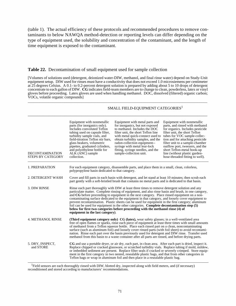
71
(table 1). The actual efficiency of these protocols and recommended procedures to remove con-taminants to below NAWQA method-detection or reporting levels can differ depending on thetype of equipment used, the solubility and concentration of the contaminant, and the length oftime equipment is exposed to the contaminant.
Table 22. Decontamination of small equipment used for sample collection
[Volumes of solutions used (detergent, deionized water-DIW, methanol, and final rinse water) depend on Study-Unitequipment setup. DIW used for rinses must have a conductivity that does not exceed 1.0 microsiemens per centimeterat 25 degrees Celsius. A 0.1- to 0.2-percent detergent solution is prepared by adding about 5 to 10 drops of detergentconcentrate to each gallon of DIW.CG indicates field-team members are to change to clean, powderless, latex or vinylgloves before proceeding. Latex gloves are used when handling methanol. DOC, dissolved (filtered) organic carbon;VOCs, volatile organic compounds]_____________________________________________________________________________________________
SMALL FIELD-EQUIPMENT CATEGORIES1
_____________________________________________________________________________________________
Equipment with nonmetallic Equipment with metal parts and Equipment with nonmetallicparts (for inorganics only). for inorganics, but not exposed parts, and rinsed with methanolIncludes convoluted Teflon to methanol. Includes the DOC for organics. Includes pesticidetubing used on capsule filter, filter unit, the short Teflon line filter unit, the short Teflonturbidity sample vials, and with metal quick-connect used to tubes for VOC sample-collec-field-titration Teflon stir bars, obtain turbidity samples, and the tion and for attaching pesticideglass beakers, volumetric radon-collection equipment-- filter unit to a sample-chamberpipettes, graduated cylinders, syringe with metal leur-lock outflow port, tweezers, and theand polyethylene bottle for fitting, syringe needles, and the short Teflon-metal hook-up
DECONTAMINATION ALK (ANC) sample sample-collection unit. line (without plastic garden-STEPS BY CATEGORY collection. hose-threaded fitting to well).________________________________________________________________________________________________________
1. PREPARATION For each equipment category, disassemble parts, and place them in a small, clean, colorless,polypropylene basin dedicated to that category.
2. DETERGENT WASH Cover and fill parts in each basin with detergent, and let stand at least 10 minutes; then scrub eachpart gently with a soft-bristled brush that contains no metal parts and is dedicated to that basin.
3. DIW RINSE Rinse each part thoroughly with DIW at least three times to remove detergent solution and anyparticulate matter. Complete rinsing of equipment, and also rinse basin and brush, in one category,andCG before proceeding to equipment in the next category. Place rinsed equipment on a non-contaminating surface dedicated to the equipment in that category, and loosely cover equipment toprevent recontamination. Plastic sheets can be used for equipment in the first category; aluminumfoil can be used for equipment in the other categories.Complete decontamination step (5)below for first two categories before proceeding with the methanol rinse (4) ofequipment in the last category).
4. METHANOL RINSE (Third equipment category only) CG (latex),wear safety glasses; in a well-ventilated areafree of open flames or sparks, rinse each piece of equipment at least three times with small amountsof methanol from a Teflon squeeze bottle. Place each rinsed part on a clean, noncontaminatingsurface (such as aluminum foil) and loosely cover rinsed parts (with foil sheet) to avoid recontami-nation. Rinse each part over the basin previously used for detergent and DIW rinse. Transfer usedmethanol from this basin to a waste container after all parts are rinsed, and before drying parts.
5. DRY, INSPECT, CG and use a portable dryer, or air dry, each part, in clean area. After each part is dried, inspect it.and STORE Replace chipped or cracked glassware, or scratched turbidity vials. Replace tubing if mold, mildew,
or imbedded sediment are present. Replace filter seals if cracked or severely crimped. Store equip-ment in the first category in two nested, resealable plastic bags, and that from other categories inTeflon bags or wrap in aluminum foil and then place in a resealable plastic bag.
________________________________________________________________________________________________________ 1Field sensors are each thoroughly rinsed with DIW, blotted dry, inspected along with field meters, and (if necessary)reconditioned and stored according to manufacturers’ recommendations.

72
Table 23. Decontamination of setup equipment used for sample collection
[Volumes of solutions used (detergent, deionized water (DIW), methanol, and final-rinse water) depend on the Study-Unit equipment setup used. DIW used for final rinse must have a specific conductance that does not exceed 1.0 mi-crosiemens per centimeter at 25 degrees Celsius. For methanol-rinsed equipment, it also should be volatile-organic-compound-free and pesticide-free. A 0.1- to 0.2-percent detergent solution is prepared by adding about 5 to 10 dropsof detergent concentrate to each gallon of DIW.CG indicates the field-team members are to change to clean, powder-less latex or vinyl gloves before proceeding. Use latex gloves when handling methanol.]________________________________________________________________________________________________________
Exterior of portable pump intake Interior of pump intake and sample-wettedDECONTAMINATION and pump tubing drawn from tubing1; including that from reel, flow manifold,STEP pump reel flowthrough chamber, and all extension lines
________________________________________________________________________________________________________
1. PREPARATION CG, raise intake from well, coil Place pump intake2 in clean standpipe.3 Route flowtubing onto plastic sheet set to from pump intake through setup to sample chamber.drain, or into plastic basin, and Temporarily attach one end of a Teflon return-flowdisconnect tubing at pump-reel line to the outflow tube in the sample chamber, andthat runs to remainder of setup. run the other end of this line back to the standpipe.
2. DETERGENT Pour detergent solution over Fill standpipe with detergent solution to level above WASH pump intake and tubing. Scrub pump intake. Begin pumping, and note the time
both gently with a soft-bristled when return-flow line has filled. Direct flow frombrush that has no metal parts. this line back into standpipe, and cycle detergent at
500 milliliters per minute for at least 5 cycles, or 10minutes. At end of cycling, add more detergent to thestandpipe, route flow to partially fill field-instrumentflowthrough chamber and waste lines. Stop pump.
3. DIW RINSE CG, raise intake and tubing CG, rinse standpipe and intake, individually, at leastabove sheet or basin, and rinse 3 times to remove detergent. Reroute flow back toat least 3 times with DIW sample chamber, add DIW to standpipe, and pump,to remove detergent and any without cycling, until grab samples from the openparticulates. Proceed to end of return-flow line (now directed to waste) indi-inspection and storage (Steps cate DIW rinse is detergent free (no sudsing). HaltNo. 6 and 7). pump. Shake flowthrough chamber to suspend any
sediment, then drain detergent from this chamber andwaste lines. Add more DIW to standpipe, start pump,route flow to the flowthrough chamber, and rinsechamber several times to remove detergent. Repeatfor waste lines. (Flowthrough chamber and wastelines are inspected and stored at this time, see below.If methanol is not required, go to Step No. 5, FINALRINSE, second paragraph).
4. METHANOL None. (Detergent scrub Reroute flow to sample chamber, and put free end of RINSE4 considered effective for return-flow line near the methanol waste container.
cleaning exterior of pump CG, rinse intake and standpipe, individually 3 times,intake and pump tubing.) place intake in standpipe, and, if possible, force air
into first several feet of pump tubing (to mark end ofDIW and beginning of methanol rinse.) Fill the standpipe with methanol to level above pump intake. Addand pump at least 2 liters of methanol into setup. If thesetup storage is less than 2 liters, collect methanolas it leaves from end of return-flow line in waste con-tainer. Halt pump. Put methanol left in standpipeinto waste container. Pump air if possible into tub-ing (to mark end of methanol). Proceed to final rinse.

73
Table 23. Decontamination of setup equipment used for sample collection--Continued________________________________________________________________________________________________________
Exterior of portable pump intake Interior of pump intake, and sample-wettedDECONTAMINATION and pump tubing drawn from tubing, including that from reel, flow manifold,STEP pump reel flowthrough chamber, and all extension lines
________________________________________________________________________________________________________
5. FINAL RINSE) None CG, and DIW rinse standpipe and intake individual- (DIW) ly at least 3 times. Add and pump DIW through setup
to sample-collection chamber and out return-flowline. On basis of air marking, line storage, and pumprate, collect methanol from return-flow line as it isforced out by final rinse. Pump at least an additional0.1 gallons of DIW through setup for every 10 feetof methanol-wetted tubing, including return-flow line,to waste after used methanol is collected.
Disconnect sample chamber from manifold, discardused chamber bag, DIW-rinse chamber frame, anddry. Repeat above for the preservation chamber.DIW rinse and dry exterior of extension lines andflow manifold. Inspect and store each piece ofequipment as it is dried according to proceduresbelow.
6. INSPECTION Simultaneously dry, inspect, and Inspect to ensure flowthrough chamber and wasterecoil tubing on pump reel. Dry lines are free of sediment. Extensions lines alsowith large, disposable, lint-free are inspected for stains, cuts, or serious abrasions.towels. Check for stains, cuts, and sediment. The flow manifold also is checkedor abrasions, and repair or replace for stains or sediment, and to ensure valves andas necessary. Check and repair quick-connect fittings are in good working order.pump intake and antibacksiphon Repair or replace as necessary to eliminate anyfor loose or missing screws. problems.
7. STORAGE Except for pump intake and suf- Store flowthrough chamber, waste lines, looped andficient pump tubing to place in- recoupled extension lines, and flow manifold in cleantake in standpipe, cover the pumpplastic bags. Place pump intake inside Teflon or otherreel and recoiled tubing with a noncontaminating bag, and then under material usedclean, plastic sheet or bag or other to cover pump-reel assembly. Fit sample and preser-noncontaminating material. Clean vation chambers with clean bags. Unless field blankspump intake as described on right. are taken, store equipment in vehicle for transport.
________________________________________________________________________________________________________1 Before their initial use, all sample lines are acid washed to remove oils and other manufacturing residues. (See
table 3.)2 Pump intake and reel tubing are that used on-site to collect samples. For a hook-up connection that attached setup
to a garden-threaded-hose valve on a water-supply pump, a small, portable pump, such as a Teflon diaphragm pumphead mounted on a 12-volt electric drive pump, or a valveless metering pump with a ceramic piston (for example, FluidMetering Instrument Model QB1-CSC or CSV) with 12-volt power can be used. Either pump is fitted with Teflonconvoluted or rigid-wall tubing (acid-washed when first obtained). The outflow tube from the pump is fitted with theappropriate quick-connect to attach it to the extension line that ran from the hook-up connection to the flow manifold(fig. 2).
3 Standpipe is of sufficient height to supply necessary head for pump intake to operate. For some pumps, such asthe Grundfos Redi-Flo2, this head requirement is critical. Standpipe also must not absorb methanol (table 3).
4 Performed when it is known or suspected that equipment was exposed to pesticides or volatile organiccompounds.

74
In general, decontamination by NAWQA field teams includes a low-phosphate, dilute-detergent wash and scrub of equipment, followed by multiple rinses with DIW (tables 22 and23). A methanol wash also is used on selected equipment that is likely to have been contaminat-ed by volatile organic compounds or pesticides.
Except for CFCs, the equipment required for decontamination, including that for safe han-dling of methanol, has been described (table 3). Decontamination of CFC sample-collectionequipment is to be done by the supplier of that equipment (Eurybiades Busenberg, U.S. Geolog-ical Survey, written commun., 1995).
During field decontamination of NAWQA equipment, it is essential that the cleaning so-lutions used be completely removed as part of the decontamination process before equipment isreused. The residual presence in sample-collection equipment of detergent and methanol canbias some measurements. Reports of organic carbon samples being affected by residues of de-tergent and methanol have been verified. Removal of methanol and detergent from pump-reellines or the purge and collection setup (fig.2) requires that adequate volumes of rinse water arepassed through these lines. Study Units can calculate the storage volume of these lines (table24). The sample-collecting setup storage volume is not only useful in estimating the amount ofdilute detergent and DIW needed for decontamination, but also is needed to determine the vol-ume of high-purity water needed for field blanks.
Ideally, the final rinse water after the methanol rinse (table 23) should not contain detect-able quantities of the analytes of interest. Study Units need to ensure that rinse-water composi-tion does not lead to equipment contamination that can ultimately compromise the interpretationof the water-quality data.
To obtain the suitable quality of DIW final rinse water for methanol-rinsed equipment,ASTM Type 1 DIW is passed through a charcoal filtration system, stored in noncontaminatingcontainers under noncontaminating conditions, and periodically analyzed to ascertain that it isfree of the compounds of interest at the method detection limit. Alternatively, NWQL volatile-and pesticide-free blank water (VPBW) can be used for the final DIW rinse.
Decontamination of equipment exposed to high concentrations of contaminants (for exam-ple, VOCs in excess of 10µg/L) could require procedures that are more rigorous than the proto-cols and recommended procedures described here and involve cleaning agents that differ fromthose commonly used (such as hexane). Whatever procedures are used, they must be document-ed by the Study Unit. This enables the National Program to identify potential problems and mod-ify procedures accordingly. Questions regarding equipment decontamination and the use ofother decontamination procedures can be directed to the NAWQA QA Specialist.

75
Table 24. Estimation of decontamination solution volumes for standpipe and sample-wettedtubing_____________________________________________________________________________________
The storage volume, Vs, of a set of pump-reel and extension lines can be estimated as follows:
Vs = [(Lp x Cp) + (Le x Ce)] + [Csp x Vsp]
where Vs is storage volume, in gallonsLp is length of pump-line segment being cleaned, in feetLe is length of extension lines, in feetCp (or Ce) = 0.023 gallons per foot for a 3/8-inch internal-diameter (ID) line
or = 0.041 gallons per foot for a 1/2-inch ID lineCsp = 0.264 gallons per liter,Vsp is volume of solution needed to fill standpipe to minimum level required tooperate pump, in liters.1
Examples:
Given: (1) Lp; the sample-wetted line segment is 100 feet for a pump-reel system that hasa 1/2-inch ID line;
(2) Le; two 10-foot, 3/8-inch ID extension lines, one running from the pump-reel outlet to the sample collection chamber, and another running from the
chamber back to the pump-reel (return-flow line to standpipe), and(3) Lsp; that the minimum volume of solution required in the standpipe to operate
the pump is 0.8 liter.
(A) Estimate the volume of detergent solution needed for the detergent wash cycle.Answer:
Vs= [(100 x 0.041)+ (20 x 0.023)] + [0.264 x 0.8] = 4.87 gallons
(B) Estimate volume of District deionized water needed to displace detergent solution.Answer: Vs, ideally.2
(C) Estimate volume of high-purity water needed to displace 2 liters of methanol just pumpedinto the system.Answer: Vs, ideally.3
_____________________________________________________________________________________1The minimal volume is that which corresponds to a level of solution in the standpipe which, if
maintained, allows the pump to operate without entraining air into flow. Once this level is reached,remove pump and measure this volume.
2Estimate assumes no mixing of the two solutions and ignores potential for detergent to adhere totubing walls. As a general rule, it is recommended that outflow from end of return-flow line be checkedfor sudsing to determine when detergent has been removed.
3Estimate assumes no mixing at the interface of the two solutions and ignores potential for methanolto adhere to tubing walls. As a general rule, it is recommended that an additional 0.1 gallons (~ 0.4 liters)of high-purity water for each 10 feet of pump and extension line used bedisplaced from sample-wettedlines (pump-reel line-to-sample chamber) to remove methanol residues. Thus in the example above,another 0.2 (= [(100 + 10) x (0.1/20)]) gallons (4 L) of DIW would be pumped from the system. Thisimplies a total of about 6.1 (= 4.9 + 1.2) gallons (24 L) of water would be used to remove methanol fromthe setup equipment.

76
Preparation of Blank Samples
To verify that decontamination is adequate, field and possibly other blanks are prepared atselected well sites in each ground-water component (see “Routine Quality-Control Samples:Type, Number, Site Selection, and Timing”; and appendix, figs. A13 (A,B), A14, A18, andA19). These field blanks are collected immediately after the equipment that was used to collectsamples at the well has been decontaminated. Methods used to obtain, process, preserve, tem-porarily store, and analyze field blanks (table 25) generally are similar to those used for corre-sponding ground-water samples (table 21). With the exception of trace-element field blanks,field blanks are analyzed using the same NWQL schedules used to analyze ground-water-qualitysamples.
Study Units are required to use specific types of water for field blanks (table 3). Generally,NWQL VPBW is required for VOC field blanks, and either NWQL VPBW or NWQL PBW isrequired for pesticide field blanks. Field blanks for dissolved organic carbon are obtained usingeither NWQL water types, but a DOC source-solution blank also must be taken (table 25, foot-note 3; and appendix, fig. A14). The QWSU IBW is required for trace-element, major-ion, andnutrient field blanks. These blank solutions are analyzed regularly (by lot number) by theNWQL to certify that they are free of measurable concentrations of NAWQA analytes. Lot num-bers are recorded by the field team as part of the required data record for NAWQA field, solu-tion, and trip blanks (see appendix, figs. A13, A14, and A19).
Except for trace elements, all field blanks are analyzed using the analytical NWQL sched-ule or laboratory code used for the corresponding ground-water-quality samples. For trace-element field blanks, NWQL schedule SC172 and laboratory codes LC0112 (As) and LC0087(Se) are used in lieu of SC2703 to obtain concentration data at method detection limits (equal toor in excess of 0.1 µg/L).
Preparation of Other Routine Quality-Control Samples andField Extracts of Pesticide Samples
As part of their data-collection activities, field teams will sometimes need to obtain, pre-pare, or process selected types of samples at some sites on the basis of required routine QC sam-pling for each ground-water component (for example, table 12). For example, the field teamoccasionally will collect replicate ground-water-quality samples at selected wells and field spikethese samples with known amounts of selected VOCs or pesticides. If VOC samples are beingcollected for a Study-Unit (or Subunit) Survey or Land-Use Study, spiked VOC ground-watersamples are required at selected sites. The field team also will submit at least one trip blank perfield season for VOCs from the field. If pesticide ground-water samples are being collected, pes-ticide field spikes are required. The field team also has the option of either extracting pesticides(under NWQL schedules SC2010 and SC2051) from spiked or unspiked ground-water samples,or sending these water-quality samples to the NWQL for extraction (under NWQL schedulesSC2001 and SC2050). Finally, if trace-element samples (SC2703) are collected, the field teamwill send three standard reference samples per field season from the field to the NWQL for anal-ysis. Each of these activities requires that special equipment be used, or that specific proceduresbe followed (described below). It is strongly recommended that field spikes, solid-phase extrac-tion, and the preparation of trip-blank and reference samples be done after all ground-water sam-ples have been collected, equipment has been decontaminated, and (if applicable) field blankshave been collected.

77
Table 25. Field-blank sample-collection protocols and procedures for ground-water componentsof the National Water-Quality Assessment Program
[DIW, District deionized water with specific conductance less than 1.0 microsiemens per liter; NWQL-VPBW, National Water Quality Laboratory volatile organic and pesticide-free blank water; NWQL-PBW, pesticide-free blank water; QWSU-IBW, Quality Water Service Unit inorganic-free blank water;DOC, dissolved (filtered) organic carbon; gal, gallons; L, liters; ~, approximately]_____________________________________________________________________________________
1. Assumptions: Equipment just used to collect ground-water samples has been decontaminatedand, except for the pump intake being in a standpipe, is set up on site in the same manner as itwas for the collection of ground-water samples.
2. Determine Blank-Solution Types and Volumes Required1:_____________________________________________________________________________________
MinimumField blank(s) Required blank- volume Required procedurecollected solution type in gal (L)
_____________________________________________________________________________________
VOCs and DOC2 NWQL-VPBW 1.5 (~ 6) Waste 0.5 gal, then collect fieldor pesticides NWQL-PBW blanks; can use DIW to forceand DOC last of VPBW or PBW water
through the system.
VOCs, DOC, NWQL-VPBW 2.0 (~ 8) Waste 0.5 gal, then collect fieldand pesticides blanks; can use DIW to force
last of VPBW or PBW waterthrough the system.
Major ions, and QWSU-IBW 1.0 (~ 4) Waste 0.5 gal, then collect fieldnutrients, or blanks; can use DIW to forcetrace elements last of IBW water through the
system.
Major ions and QWSU-IBW 1.5 (~ 6) Waste 0.5 gal, then collect fieldnutrients, and blanks; if necessary, use DIW totrace elements force last of IBW water through
the system.
Combinations of NWQL-VPBW or 1.5 to 2.0 Waste 0.5 gal of the VPBW ororganics and in- NWQL-PBW and PBW water, then collect organicorganics above QWSU-IBW 1.0 to 1.5 field blanks; can use the IBW water
to force the VPBW or PBW waterthrough the system; waste 0.5gal of IBW water, then can collectinorganic field blanks using DIWto force IBW water through thesystem.

78
Table 25. Field-blank sample-collection protocols and procedures for ground-water componentsof the National Water-Quality Assessment Program--Continued_____________________________________________________________________________________________
3. General Field-Blank Collection Procedure--The procedure for collection of blanks assumes or-ganic (VOC--SC2090, SC2091, or SC2092, Pesticide--SC2001 or SC2010 and SC2050 or SC2051,and DOC--SC2085) and inorganic (Trace-element--SC2703, Major ion--SC2750, and Nutrient--SC2752) field blanks are collected. This is the most complex type of field-blank collection.3
• Divide Field-Team Duties--Recommend that a three-person team be used. The standard two-person field team collects samples in a manner similar to that used to collect ground.-water samples;the third person adds blank water(s) to standpipe, and controls flow through system as needed tofacilitate field-blank collection.
• Check Flow Setup--from standpipe to sample collection chamber (fig.2), ensure that adequate vol-umes of DIW and the required blank water(s) are arranged in order and within easy reach of personstationed at standpipe.
• Set Low Flow Rate--Once pumping is initiated, set flow (on basis of measurement at chamber out-flow) to about 0.1 gal. (500 mL) per minute or less to avoid wasting excessive amounts of blankwater.
• Route blank solutions in presorted manner--As solutions are changed, pump operator should changeto clean gloves, empty residual solution from standpipe, and rinse pump intake and standpipe, indi-vidually, at least three times each, with the next solution, and attempt to pump air segment into pumpline before adding next solution to standpipe to mark change in solution type.
If air segment cannot be used to mark end of one solution and beginning of next, then the change insolutions is determined solely on the basis of the storage volume in lines (table 24) divided by thepumping rate (estimated above) to determine the time it takes for the solution to travel from thestandpipe to the outflow chamber. Once pump is started, and this time has elapsed, it is assumedthe correct solution is flowing from chamber outflow.
Regardless of whether air segments or timed flow or both are used to assess when the desiredsolution arrives at the chamber, 0.5 gal (~ 2 L) of the solution are passed to waste before the fieldblanks that require that water type are collected.
To limit the amount of blank water used, and left standing in pump-reel or extension lines after allsamples that require that blank-water type have been collected, one type of water can be used toforce the last of another type from the lines and to the chamber for collection.
• Collect field blanks in prescribed manner --The order, manner, and quality-control measures andchecks associated with obtaining, processing, preserving, and temporarily storing field blanks areidentical to the order, manner, and quality-control measures and checks that would be used to collecta corresponding set of ground-water-quality samples (see table 21).

79
Table 25. Field-blank sample-collection protocols and procedures for ground-water componentsof the National Water-Quality Assessment Program--Continued_____________________________________________________________________________________________
4. Break Down Equipment Setup--After field blanks have been collected, equipment is broken downand stored, accordingly (see tables 22 and 23). Exceptions include filter units using filter mem-branes that are removed and discarded, and the sample preservation chamber. If filters for organics(pesticides and DOC) were used, the units are opened and filters discarded. Units are final rinsed,reassembled and stored (see table 22, step 5, and table 23, step 7). The sample-preservation chamberalso is decontaminated before it is stored.
____________________________________________________________________________________________1If portable pump was used, the same pump and length of pump line used to collect ground-water samples is
decontaminated and used to obtain field blanks.2Note that VPBW and PBW are not certified free of organic carbon. A solution blank of that lot of water used
for the DOC field blank is sent to the NWQL for DOC analysis (see footnote no. 3 below).3NWQL-PBW cannot be used for VOC field blanks. Either NWQL water type can be used for DOC field blank,
but both water types contain about 0.1 mg/L of organic carbon. A solution blank sample of water from the same lotof NWQL water used for DOC field blank, poured directly into DOC 125-mL amber sample bottle) is required forevery DOC field blank. The lot number of the water used for the solution blank is recorded on the ASR form (seeappendix, fig. A14).
4With one exception, samples are analyzed using NAWQA schedules. The exception is trace-element fieldblanks, for which the low-level NWQL blank schedule (SC172 with laboratory codes added for arsenic andselenium) is recommended (see appendix, fig. A18).

80
Pesticide and volatile-organic-compound (VOC) spiked samples
Required equipment and procedures to spike ground-water samples in the field are ob-tained from the NWQL in kits prepared for the NAWQA Program (table 3). Training in fieldspiking is required, and can be obtained through the basic course required for NAWQA ground-water field teams (table 6). Because of the need for recovery and variability data on field spikesfor the National Program, Study Units that wish to modify spike equipment or procedures as de-scribed below, or in NWQL kits for the NAWQA Program, by using different spike solutions orvolumes for routine QC spiked samples, are to discuss their plans with the National Program(NAWQA QA Specialist).
At each site where pesticide field spikes are scheduled, at least three 1.0-L ground-watersample bottles are required foreach NWQL pesticide schedule (SC2001 or SC2010 and SC2050or SC2051). These samples are collected sequentially during the collection of ground-water-quality samples and chilled (table 21). One bottle for each schedule serves as the ground-water-quality sample for the well. It also serves as a background sample (to determine what pesticides,if any, were present in the other two sample bottles before they were spiked). The other two sam-ple bottles are used for replicate field spikes. Each of these is spiked with 100µL of NWQL-pesticide-spike solution.
Currently, for VOC field spikes (SC2090, SC2091, or SC2092), at least seven sample vialsof ground water are collected sequentially and chilled (table 21). Three vials are needed for theground-water-quality sample, which also is the background sample for the field-spiked samples.Replicate, field-spiked VOC samples (consisting of two vials each) are prepared by spiking eachvial with 100µL of NWQL-VOC-spike solution.
In general, all samples (pesticide or VOC) are spiked with 100µL of spike solution, whichresults in a concentration of about 1 to 3 mg/L, depending on the analyte. If the background sam-ple concentration of the analyte (in the unspiked sample) exceeds about one-tenth the concentra-tion in spiked samples, the recovery data from spiked samples generally is considered positivelybiased (dependent in part on the amount of analyte present before spiking). Use of a volume ofspike solution in excess of 100µL, or a spike solution with higher concentrations than that com-monly prepared by the NWQL, could reduce the bias. Recovery data from the use of such a spikesolution, however, will relate only to the high, and not the low, concentrations of the analyte.
Once prepared, field-spiked samples are chilled to 0 to 4°C, and generally treated in a man-ner identical to that of the corresponding background sample. Important information that relatesto the spiked sample (lot number, volume, and source of spike solution) are recorded on fieldand NWQL ASR forms (appendix, fig. A12).
Pesticide solid-phase extractions
The option is available for Study Units to extract pesticides from ground-water-qualitysamples (unspiked and spiked) or field blanks in the field, rather than having extractions done atthe NWQL. Extracts are collected on solid-phase cartridges and sent to the NWQL for analysisunder SC2010 and SC2051. Extraction equipment and procedures, prepared by the NWQL for

81
NAWQA, can be obtained from HIF or NWQL (table 3). Training in the extraction procedureis required, and is obtained through the basic course required for NAWQA ground-water sam-pling field teams (table 6).
The decision to submit solid-phase extracts instead of water samples to the NWQL requirescareful consideration. Field extractions are practical and should be considered in situationswhere transporting glass bottles, shipping weights, or shipping times pose a serious problem.Extraction is recommended if pesticide water samples (for SC2001 and SC2050) cannot beshipped and reach the laboratory within 72 hours after collection, or when information is avail-able that indicates the analytes of interest could degrade rapidly during transit. Field extractionsalso are recommended if the transportation of large, glass, sample bottles, or the sheer weight ofwater samples, poses a hazard for the samples or the field team (for example, if wells are locatedin remote areas that are accessible only by foot or light plane).
For Study Units that require a quick turnaround time on analytical results, sending fieldextractions rather than water samples, particularly at peak production times at the NWQL, couldexpedite data returns. The Study Unit should contact the NWQL in advance of adopting thisstrategy, however, as there may be no backlog in analysis. In addition, special handling toexpedite analysis can be arranged with the NWQL at an additional cost.
Sending field extractions instead of water samples has another potential benefit. Field ex-tractions allow the field team to extract less than a liter of sample, which is useful if water sam-ples are known or suspected to contain concentrations that exceed the linear operating range ofNWQL methods (currently about 100µg/L). In such cases, a measured (by weight difference)sub-volume of the original 1-L water sample can be extracted. As an alternative, however, thefield team can request that the NWQL extract only part of a water sample (use comment line onNWQL ASR form), and thereby achieve the same results.
Field extractions can reduce the costs of NWQL analysis and overnight shipping, particu-larly if the Study Unit is some distance from the NWQL. Whether or not sending field extrac-tions instead of water samples is cost effective depends on whether or not the reduced costs inanalysis and shipping are less than the cost of obtaining, using, and maintaining extraction equip-ment and related supplies. The cost and time of labor associated with extracting samples alsoshould be factored into the decision. A 1-L sample typically requires one field-team memberabout 45 minutes to extract, not including the time and labor cost needed for equipment assemblyand decontamination. Overall, Johnson and Swanson (1994) found laboratory processing re-quired 32 percent fewer hours than on-site processing of extracts by a field team for each of twoprototype sites in the Central Nebraska Study Unit.
The time involved to set up equipment, conduct the extraction, and decontaminate, disas-semble, and store this equipment can make it difficult for a two-person field team to perform ex-tractions on-site at every well, given all the other on-site activities that the field team typicallyis required to perform. Therefore, extractions usually are performed after most other on-site ac-tivities are completed. Alternatively, extractions can be performed by a third person, perhapsoff-site at a designated facility. This is probably the only practical method to field extract nu-merous pesticide samples in the field. For example, each routine QC site for pesticides requires

82
a minimum of six field extractions (one 1-L ground-water sample, plus two 1-L spiked ground-water samples for each of the two pesticide schedules).
VOC trip-blank and trace-element standard reference samples
Two types of routine QC samples require no sample collection, but are routinely sent fromselected sites in the field--the VOC trip blank and the standard trace-element reference sample(table 10). Neither is ever opened by Study Unit personnel.
The VOC trip blank can be found in the box in which NWQL VOC vials are shipped.When shipped by the NAWQA team from the field, the lot number (if not on the vial) can befound on the box, and is recorded on the NWQL ASR form sent with the vial (appendix, fig.A15).
Each Study Unit that conducts trace-element sampling in a given field season must requestthree standard trace-element reference samples from the BTD&QS (table 10). These referencesamples are sent from different ground-water sites by the field team during that field season. Ateach site, the field team records on the NWQL ASR form the original sample identification codefound on each bottle and relabels the bottle with the site identification code (appendix, fig. A19)before the sample is shipped.
Handling and Shipping of Samples
Handling and shipping protocols divide ground-water-quality and routine QC samples col-lected at a well into three groups (table 26). One group requires samples be shipped overnightat less than 4°C. Another group can be shipped by surface (first class) mail at an ambient tem-perature. The third group is stored by the Study Unit, and possibly shipped for analysis at a laterdate by surface mail.
To ensure that the samples collected will provide the data desired, the field team verifiesthat all sample containers required from the well are present, and that all the information requiredon container labels and field, NWQL-ASR, and other forms, is complete. It is important that thecontainers are properly labeled, and that all forms contain the information needed by the NWQLand the Study-Unit data manager (see appendix).
Samples that require overnight shipping (table 26, Group One) can undergo physical, bio-logical, or radiochemical transformation or degradation within a short period of time. This isreflected in their maximum holding times (elapsed time between sample collection and analy-sis). The maximum holding time for Group One samples is 3 to 5 days, except for VOCs, whichhave a 14-day holding time. Holding times for most of these samples are dependent on main-taining low sample temperature (less than 4°C). During the period when most samples are beingsent to the NWQL (about April through October), at least half the holding time can expire afterthese samples reach NWQL login and before they are analyzed. Thus, all of these samples mustbe shipped without delay. In addition, and except for radon, these samples also must be packedin a sufficient amount of ice to maintain low temperatures until received at NWQL and refriger-ated.

83
Table 26. Sample handling for shipment of ground-water-quality and quality-control samples
[°C, degrees Celsius; lbs, pounds; mil, manufacturer bag thickness; SASE, self addressed and stampedenvelope; NWQL, National Water Quality Laboratory; ASR, Analytical Service Request; SC or LC,NWQL schedule or laboratory code; FCC, FA, FU, and RU are bottle-type designations; CFC,chlorofluorocarbon]
Sample Shipping Procedures
Group One:Volatiles--SC2090, SC2091, and SC2092Pesticides--SC2001 and SC2050 or SC2010 and SC2051Nutrients--SC2752-FCCOrganic Carbon--SC2085(Add small (250-mL) poly-ethylene bottle filled with waterand labeled “For TemperatureCheck, at Login.”)
Overnight at 0 to4°C, and for safehandling, at weightless than 50 lbs.
Place samples in mesh bag andplace “Temperature Check”bottle in middle of sample contain-ers. Place a large, 4-mil plastic bagin cooler, add layer of ice, andplace mesh bag on ice inside plas-tic bag. Surround and cover meshbag with ice, then twist and sealouter plastic bag with waterprooftape.
Radon--LC1369 Overnight (withabove or separatefrom above).
Place resealable plastic bag con-taining radon tube(s) atop largeplastic bag above. Combine ASRforms with Study-Unit Login replyform and SASE in nested, reseal-able, plastic bags, and tape toinside of cooler lid. Put returnaddress on inside of lid. Close lid,secure it, and cooler drain cap withstrong tape. Attach air bill.
Group Two:Major ions--SC2750--FA FU, and RUTrace elements--samplesSC2703 (blanks--SC172)
Surface, first-classmail, at ambient tem-perature and, for safehandling, weight lessthan 50 lbs.
Place trace-element samples in twonested, resealable plastic bags andplace sealed bags in a heavy card-board container; pack in bubblepack, enclose forms (ASR andlogin-reply forms, and SASE) innested, resealable plastic bags.Seal container with strong tape andattach mailing label with returnaddress.
Group Three:Isotopes of tritium, deuterium,and oxygen; major-ion (archive)sample (SC2750--FA); andpossibly CFC samples
Initially archive in adry, cool, and cleanstorage area; possi-bly ship (via regularsurface mail).
Archive individual samples in apartitioned, heavy cardboard con-tainer. List sample types and dateon side of container. Also archiveASR and any other forms.

84
To verify that low temperatures are maintained, each overnight shipment includes a small(250-mL) polyethylene bottle filled with uncontaminated water (for example, deionized),marked “For Temperature Check at Login.” This bottle is placed in the middle of the other sam-ples being shipped. The NWQL login personnel will check the temperature of the water in thisbottle, record it on the Study-Unit’s “Login-Reply Return Form” (appendix, fig. A20), and re-turn this form via the self-addressed and stamped envelope provided by the Study Unit. Thisform and envelope initially are included with the NWQL ASR forms, which are double baggedin resealable plastic bags, and taped to the inside of the shipping cooler (table 26). Study-Unitdata managers are to file the return forms, and keep a record of sample temperatures, particularlythose that exceeded 4°C.
As a rule, water-quality samples with 3- to 5-day holding times should not be collectedon a Friday, particularly Fridays associated with 3-day weekends, because 3 to 5 days couldelapse before samples are analyzed. Radon, with a short half-life of approximately 3.6 days, isdefinitely not collected if it cannot be shipped within 24 hours of collection and arrive at NWQLlogin before 12:00 p.m. on any Friday.
Samples sent by regular surface mail (first class) have longer holding times than overnightsamples and do not need to be chilled (table 26, Group Two). It is recommended, however, thatthese samples be shipped within a week or two of collection.
Samples archived by the Study Unit (table 26, Group Three) can include replicates (distinctfrom those required for routine QC samples) of major ions (SC2750, FA bottle only), trace ele-ments (for example, SC2703), isotope samples (for tritium, deuterium, and oxygen), and chlo-rofluorocarbon (CFC) samples. Archived major-ion and trace-element samples should bediscarded as soon as it is known that analytical reruns are not required. Isotope samples can beheld for several years provided bottles remain sealed. Samples for CFCs can be held for at leastseveral years, provided they are not biologically active (Eurybiades Busenberg, U.S. GeologicalSurvey, written commun., 1995).
REFERENCES CITED
Alley, W.M., ed., 1993, Regional ground-water quality: New York, Van Nostrand Reinhold, 634 p.
Alley, W.M., and Cohen, Philip, 1991, A scientifically based nationwide assessment of ground-water quality in the United States: Environmental Geology and Water Science, v. 17, no. 1,p. 17-22.
Bachman, L.J., Shedlock, R.J., and Phillips, P.J., 1987, Ground-water-quality assessment of theDelmarva Peninsula, Delaware, Maryland, and Virginia--Project description: U.S. Geologi-cal Survey Open-File Report 87-112, 18 p.
Busenberg, Eurybiades, and Plummer, L.N., 1987, pH measurement of low-conductivity waters:U.S. Geological Survey Water-Resources Investigations Report 87-4060, 22 p.
Busenberg, Eurybiades, and Plummer, L.N., 1992, Use of chlorofluorocarbons (CCl3F and CCl2F2)as hydrologic tracers and age-dating tools--the alluvium and terrace system of central Okla-homa: Water Resources Research, v. 28, no. 9, p. 2257-2283.

85
Christenson, S.C., and Parkhurst, D.L., 1987, Ground-water-quality assessment of the CentralOklahoma aquifer, Oklahoma--Project description: U.S. Geological Survey Open-FileReport 87-235, 30 p.
Christenson, S.C., and Rea, A.H., 1993, Ground-water quality in the Oklahoma City urban area,inAlley, W.M., ed., Regional Ground-Water Quality: New York, Von Nostrand Reinhold,p. 589-611.
Cohen, Philip, Alley, W.M., and Wilber, W.G., 1988, National water-quality assessment--futuredirections of the U.S. Geological Survey: American Water Resources Association, WaterResources Bulletin, v. 24, no. 6, p. 1147-1151.
Ferree, D.M., Christenson, S.C., Rea, A.H., and Meander, B.A., 1992, Ground-water-qualityassessment of the Central Oklahoma aquifer, Oklahoma--Hydrologic, water-quality, andquality-assurance data, 1987-90: U.S. Geological Survey Open-File Report 92-641, 193 p.
Gibs, Jacob, and Imbrigotta, Thomas, 1990, Well-purging criteria for sampling purgeable organiccompounds: Ground Water, v. 28, no. 1, p. 68-78.
Gilliom, R.J., Alley, W.M., and Gurtz, M.E., 1995, Design of the National Water-Quality Assess-ment Program--occurrence and distribution of water-quality conditions: U.S. GeologicalSurvey Circular 1112, 33 p.
Hamilton, P.A., Denver, J.M., Phillips, P.J., and Shedlock, R.J., 1993, Water-quality assessmentof the Delmarva Peninsula, Delaware, Maryland, and Virginia--effects of agricultural activ-ities on, and distribution of, nitrate and other inorganic constituents in the surficial aquifer:U.S. Geological Survey Open-File Report 93-40, 87 p.
Hamilton, P.A., Shedlock, R.J., and Phillips, P.J., 1992, Water-quality assessment of the DelmarvaPeninsula, Delaware, Maryland, and Virginia--analysis of available ground-water-qualitydata through 1987: U.S. Geological Survey Water-Supply Paper 2355-B, 65 p.
Hardy, M.A., Leahy, P.O., and Alley, W.M., 1989, Well installation and documentation, andground-water sampling protocols for the pilot national water-quality assessment program:U.S. Geological Survey Open-File Report 98-396, 36 p.
Hirsch, R.M., Alley, W.M., and Wilber, W.G., 1988, Concepts for a national water-quality assess-ment program: U.S. Geological. Survey Circular 1021, 42 p.
Johnson, S.M., and Swanson, R.B., 1994, Operational procedures for collecting water-quality sam-ples at monitoring sites on Maple Creek near Nickerson and the Platte River at Louisville,Eastern Nebraska: U.S. Geological Survey Open-File Report 94-121, 24 p.
Koterba, M.T., Banks, W.S.L., and Shedlock, R.R., 1993, Pesticides in shallow ground-water inthe Delmarva Peninsula: Journal of Environmental Quality, v. 22, no. 3, p. 500-518.
Koterba, M.T., Dysart, J.E., Phillips, S.W., and Zynjuk, L.D., 1994, Use and value of quality-control data in studies in the Chesapeake Bay Region,in Proceedings of the National Sym-posium on Water-Quality, American Water Resources Association, Chicago, Ill., November5-11, p. 65-74.
Koterba, M.T., Shedlock, R.J., Bachman, L.J., and Phillips, P.J., 1991, Regional and targetedground-water-quality networks in the Delmarva Peninsula, chapter 6,in Nash, R.G., andLeslie, A.R., eds., Ground-Water Residue Sampling Design, American Chemical Sympo-sium Series 465, American Chemical Society, Washington DC, p. 111-138.

86
Lapham, W.W., Wilde, F.D., and Koterba, M.T., in press, Ground-water data-collection protocolsand procedures for the National Water-Quality Assessment Program--selection, installation,and documentation of wells, and collection of related data: U.S. Geological Survey Open-File Report 95-398.
Leahy, P.P., Rosenshein, J.S., and Knopman, D.S., 1990, Implementation plan for the NationalWater-Quality Assessment program: U.S. Geological Survey Open-File Report 90-174, 10 p.
Leahy, P.P., and Wilber, W.G., 1991, The National Water-Quality Assessment (NAWQA) Pro-gram--A basis for water-resource policy development: Irrigation and Drainage Proceedings,July 22-26, 1991, IR Div/ASCE, Honolulu, Hawaii, p. 711-717.
Mattraw, H.C., Jr., Wilber, W.G., and Alley, W.M., 1989, Quality-assurance plan for the pilotnational water-quality assessment program: U.S. Geological Survey Open-File Report89-726, 21 p.
Radtke, D.B., and Wilde, F.D., eds., in press, National field manual for collection of water-qualitydata--Field measurements: U.S. Geological Survey Techniques of Water-Resources Investiga-tions, book 9, chap. A6.
Rea, A.H., in press, Factors related to water quality in the Central Oklahoma aquifer,in Christen-son, Scott and Havens, J.S., eds., Ground-water-quality assessment of the Central Oklahomaaquifer--results of investigations: U.S. Geological Survey Open-File Report 93-441.
Reilly, T.E., Franke, O.L., and Bennett, G.D., 1989, Bias in groundwater samples caused by well-bore flow: Hydraulic Engineering Journal, v. 115, no. 2, p. 270-276.
Reynolds, G.W., Hoff, J.T., and Gillham, R.W., 1990, Sampling bias caused by materials used tomonitor halocarbons in ground water: Envrionmental Science & Technology, v. 24, no. 1,p. 135-142.
Shampine, W.J., Pope, L.M., and Koterba, M.T., 1992, Integrating quality assurance in projectwork plans of the U.S. Geological Survey: U.S. Geological Survey Open-File Report 92-162, 12 p.
Smith, R.A. and Alexander, R.B., 1989, Reply To: Discussion by A.R. Russell and K.H. Coale on“Trends in lead concentrations in major U.S. rivers and their relation to historical changes ingasoline-lead consumption”: Water Resources Bulletin, v. 25, no. 6, p. 1279-1281.
van der Kamp, G., and Keller, C.K., 1993, Casing leakage in monitoring wells--detection, confir-mation, and prevention: Ground Water Monitoring & Remediation, v. 13, no. 4, p. 136-141.
Welch, A.H., and Plume, R.W., 1987, Water-quality assessment of the Carson River ground-waterbasin, Nevada and California--project description: U.S. Geological Survey Open-File Report87-104, 27 p.

APPENDIX. EXAMPLES OF FIELD FORMS FOR THE COLLECTION OFGROUND-WATER DATA AND SAMPLES FOR THE NATIONAL WATER-QUALITY
ASSESSMENT PROGRAM
Examples of field and analytical service request forms for the National Water QualityLaboratory are provided in this appendix. Included are forms for the following:
A1. Land-use and land-cover field sheet for the 1991 Study Units, National Water-Quality AssessmentProgram.1
A2. Example of quality-control and calibration form for the dissolved-oxygen sensor and meter.A3. Example of quality-control and calibration form for the specific electrical conductance sensor and
meter.A4. Example of quality-control form for a thermistor thermometer.A5. Example of quality-control form for a pH sensor and meter.A6. Theoretical slope values of Nerst equation for pH electrode (modified from Plummer and
Busenberg, 1981).A7. Example of a purge form for a well.A8. Example of a ground-water-quality sample-collection field form.A9. Example of field-titration form.A10-A. Example of an analytical service request form for primary ground-water-quality samples that
require overnight shipping.A10-B. Example of an analytical service request form for primary ground-water-quality samples that can
be shipped surface (first class) mail.A11-A. Example of an analytical service request form for replicate ground-water-quality samples that
require overnight shipping.A11-B. Example of an analytical service request form for replicate ground-water-quality samples that can
be shipped surface (first class) mail.A12-A. Example of an analytical service request form for replicate field-spiked, ground-water samples for
pesticides and volatile organic compounds: first set, TIME: HH:02.A12-B. Example of analytical service request form for replicate field-spiked, ground-water samples for
pesticides and volatile organic compounds: second set, TIME: HH:03. (If optional third set istaken, use a third form similar to the one above but with TIME: HH:04.)
A13-A. Example of analytical service request form for field blanks that require National Water QualityLaboratory blank waterand overnight shipping.
A13-B. Example of an analytical service request form for field blanks that require Quality of Water ServiceUnit inorganic-free blank water (QWSU-IBW)and surface mail shipping.
A14. Example of an analytical service request form for dissolved (filtered) organic carbon (DOC)solution blank composed of either NWQL volatile pesticide-free blank water (VPBW) orpesticide-free blank water (PBW).
A15. Example of an analytical service request form for a volatile-organic-compound (VOC) trip blank.A16. Example of an analytical service request form for a primary trace-element ground-water sample
(SC2703).A17. Example of an analytical service request form for a replicate trace-element ground-water sample
(SC2703).A18. Example of an analytical service request form for a ground-water trace-element (SC2703) field
blank.A19. Example of an analytical service request form for a standard-reference trace-element (SC2703)
sample for ground water.A20. Example of Study Unit login reply form sent with samples shipped by overnight mail.
1Land-use and land-cover field sheet for the 1991 Study Units is being evaluated for use by the 1994 Study Units.
87
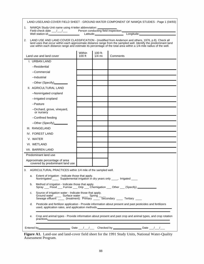
LAND-USE/LAND-COVER FIELD SHEET - GROUND-WATER COMPONENT OF NAWQA STUDIES - Page 1 (04/93)
1. NAWQA Study-Unit name using 4-letter abbreviation: ____________Field-check date ___/___/___ Person conducting field inspection:__________________________________Well station-id: ___________________ Latitude:__________________ Longitude:_______________________
2. LAND USE AND LAND COVER CLASSIFICATION - (modified from Anderson and others, 1976, p.8). Check allland uses that occur within each approximate distance range from the sampled well. Identify the predominant landuse within each distance range and estimate its percentage of the total area within a 1/4-mile radius of the well.
3. AGRICULTURAL PRACTICES within 1/4 mile of the sampled well.
a. Extent of irrigation - Indicate those that apply.Nonirrigated ____ Supplemental irrigation in dry years only ____, Irrigated ____
b. Method of irrigation - Indicate those that apply.Spray ___ Flood ___ Furrow ___ Drip ___ Chemigation ___ Other ___ (Specify) ____________
c. Source of irrigation water - Indicate those that apply.Ground water ____ Surface water ____ Spring __ __Sewage effluent ____ (treatment): Primary ____ Secondary ____ Tertiary ____
d. Pesticide and fertilizer application - Provide information about present and past pesticides and fertilizersused, application rates, and application methods.____________________________________________________________________________________________________________________________________
e. Crop and animal types - Provide information about present and past crop and animal types, and crop rotationpractices.__________________________________________________________________________________________________________________________________________________________________
Entered by____________________ Date ___/___/___ Checked by __________________ Date ___/___/___
Figure A1. Land-use and land-cover field sheet for the 1991 Study Units, National Water-QualityAssessment Program.
Land use and land coverWithin100 ft
100 ft-1/4 mi Comments
I. URBAN LAND
--Residential
--Commercial
--Industrial
--Other (Specify)________
II. AGRICULTURAL LAND
--Nonirrigated cropland
--Irrigated cropland
--Pasture
--Orchard, grove, vineyard, or nursery
--Confined feeding
--Other (Specify)________
III. RANGELAND
IV. FOREST LAND
V. WATER
VI. WETLAND
VII. BARREN LAND
Predominant land use
Approximate percentage of areacovered by predominant land use
88

LAND-USE/LAND-COVER FIELD SHEET - GROUND-WATER COMPONENT OF NAWQA STUDIES-Page 2 (04/93)
Well station-id: ______________________________ Field-check date: ____/____/____
4. LOCAL FEATURES - Indicate all local features that may affect ground-water quality which occur within eachapproximate distance range from the sampled well.
Figure A1. Land-use and land-cover field sheet for the 1991 Study Units, National Water-QualityAssessment Program--Continued.
Feature within100 ft
100 ft -1/4 mi
Comments
Gas station
Dry cleaner
Chemical plant orstorage facility
Airport
Military base
Road
Pipeline or fuelstorage facility
Septic field
Waste disposal pond
Landfill
Golf course
Stream, river, or creekPerennial __Ephemeral __
Irrigation canalLined __ Unlined __
Drainage ditchLined __ Unlined __
LakeNatural __ Manmade __
ReservoirLined __ Unlined __
Bay or estuary
Spring Geothermal (> 25 C)__ Nongeothermal__
Salt flat or playaDry __ Wet __
Mine, quarry, or pitActive __Abandoned__
Oil well
Major withdrawal well
Waste injection well
Recharge injection well
Other ______________
89

LAND-USE/LAND-COVER FIELD SHEET - GROUND-WATER COMPONENT OF NAWQA STUDIES -Page 3 (04/93)
Well station-id: ______________________________ Field-check date: ____/____/____
5. LAND-USE CHANGES - Have there been major changes in the last 10 years in land use within 1/4 mile ofthe sampled well? Yes __, Probably __, Probably not __, No __ If yes, describe major changes.__________________________________________________________________________________
__________________________________________________________________________________
__________________________________________________________________________________
__________________________________________________________________________________
__________________________________________________________________________________
__________________________________________________________________________________
6. ADDITIONAL COMMENTS - Emphasize factors that might influence local ground-water quality.__________________________________________________________________________________
__________________________________________________________________________________
__________________________________________________________________________________
__________________________________________________________________________________
__________________________________________________________________________________
Remarks
Figure A1. Land-use and land-cover field sheet for the 1991 Study Units, National Water-QualityAssessment Program--Continued
90

Tabl
e 1:
Mod
el _
____
____
____
____
____
____
___;
Ser
ial N
umbe
r (W
) __
____
____
____
____
__
Ele
ctro
de C
ondi
tion
Cal
ibra
tion
Dat
eT
ime
Mem
bran
eM
embr
ane
chan
ged
last
Gol
dca
thod
ean
d si
lver
anod
e
Ele
ctro
-ly
teB
atte
ryR
ed-
line
Zer
o
Met
er1
tem
per-
atur
e(o C
)
Sat
urat
edD
O a
tte
mpe
ratu
re(m
g/L)
Atm
o-sp
heric
.pr
essu
re(m
m H
g)
Cor
rect
ion
fact
or
Cal
ibra
-tio
nD
O(m
g/L)
Adj
uste
d (
Y o
r N
)
Initi
als
of
test
or
o C =
deg
rees
Cel
sius
; mg/
L =
mill
igra
m p
er li
ter;
mm
Hg
= m
illim
eter
s of
mer
cury
1 See
tem
pera
ture
qua
lity-
cont
rol f
orm
for
ther
mis
tor
used
with
this
inst
rum
ent (
fig. A
4).
Fig
ure
A2.
Exa
mpl
e of
qua
lity-
cont
rol a
nd c
alib
ratio
n fo
rm fo
r th
e di
ssol
ved-
oxyg
en (
DO
) se
nsor
and
met
er.
91
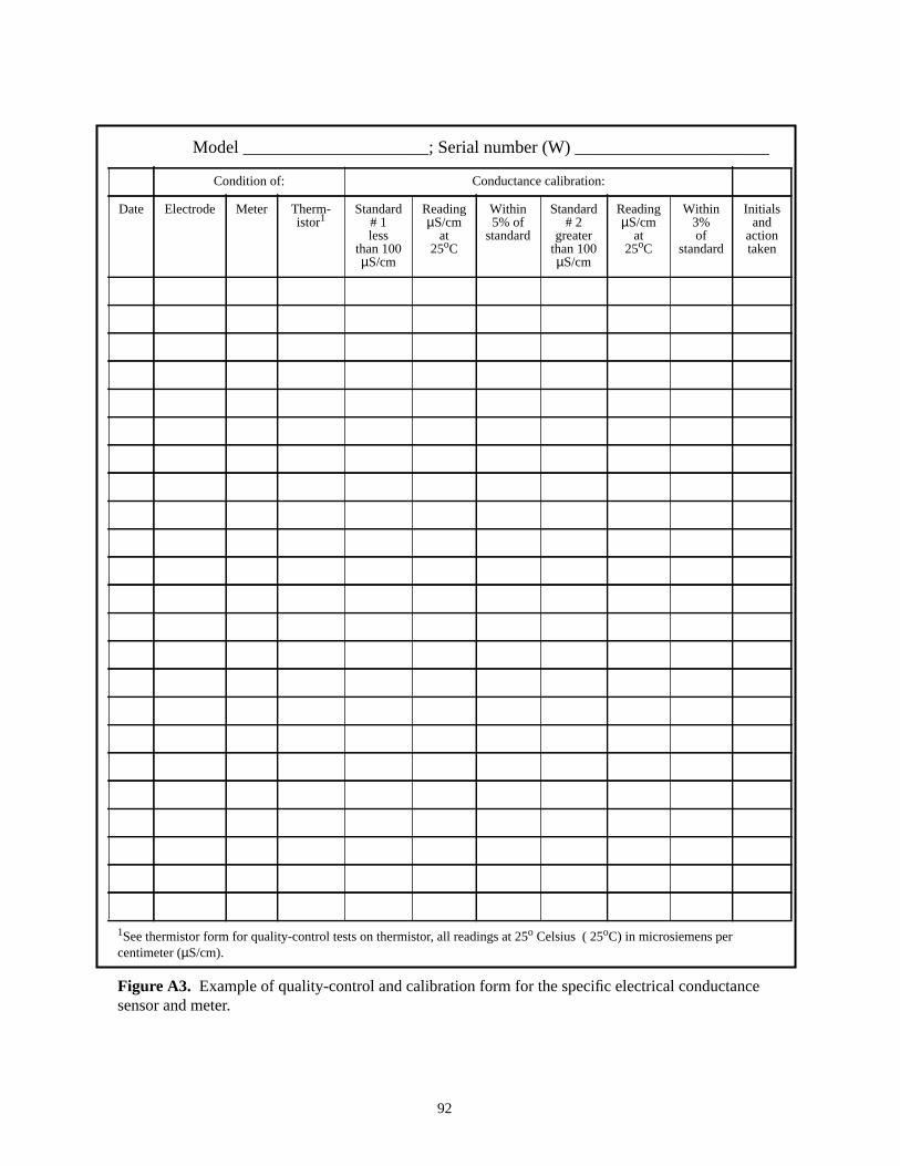
Table 1: Model _____________________; Serial number (W) ______________________
Condition of: Conductance calibration:
Date Electrode Meter Therm-istor1
Standard# 1less
than 100µS/cm
ReadingµS/cm
at25oC
Within5% of
standard
Standard# 2
greaterthan 100µS/cm
ReadingµS/cm
at25oC
Within3%of
standard
Initialsand
actiontaken
1See thermistor form for quality-control tests on thermistor, all readings at 25o Celsius ( 25oC) in microsiemens percentimeter (µS/cm).
Figure A3. Example of quality-control and calibration form for the specific electrical conductancesensor and meter.
92

Table 2: Model ____________________ Serial number (W) __________________
Low temperature (0 to 5oC) High temperature (15 to 35oC)
Date ASTMthermometer1
reading (oC)
Meterreading (oC)
Within0.2oC?
ASTMthermometerreading (oC)
Meterreading (oC)
Within0.2oC?
Actiontaken
Initials
1American Society for Testing and Materials (ASTM) thermometer, serial number _______________________.Specify thermistor use by checking one below:pH ____ Specific electrical conductance ____ Dissolved oxygen ____ Turbidity ____ Temperature _____
Figure A4. Example of quality-control form for a thermistor thermometer measuring degrees Celsius (oC).
93

Table 3:
Reading Reading
Date LowpH
buffer
HighpH
buffer
mVlow
mVhigh
pHlow
pHhigh
Buffertemper-ature(oC)
Actualslope1
∆mV/∆pH
Theoret-ical
slope attemper-ature2
Sloperatio3
(%)
Pass(YorN)
Responsetime4
(seconds)
Initials/actiontaken5
1Actual slope =∆mV/∆pH, where∆mV is difference in millivolt readings between low and high pH buffers, and∆pH is difference inmeasured pH (that meter locks on) between low and high pH buffers.
2Theoretical slope of Nernst equation (see fig. A6) as function of buffer temperature in degrees Celsius (oC).3Slope ratio in percent = (actual slope/theoretical slope) x 100. An acceptable ratio is one greater than or equal to 95.0 percent.4Response time for meter to lock onto low pH buffer after calibration on high pH buffer. An acceptable value is less than or equal to
15 seconds.5Initials of person performing quality control, and action taken by that person. See temperature quality-control form for thermistor used
with this instrument (fig. A4).
Figure A5. Example of quality-control form for a pH sensor and meter.
94

Table 4:
Temperature1 Theoretical slope2 Temperature Theoretical slope
0 54.197 21 58.364
1 54.396 22 58.562
2 54.594 23 58.761
3 54.792 24 58.959
4 54.991 25 59.157
5 55.189 26 59.356
6 55.388 27 59.554
7 55.586 28 59.753
8 55.784 29 59.951
9 55.983 30 60.149
10 56.181 31 60.348
11 56.380 32 60.546
12 56.578 33 60.745
13 56.777 34 60.943
14 56.975 35 61.141
15 57.173 36 61.340
16 57.372 37 61.538
17 57.570 38 61.737
18 57.769 39 61.935
19 57.967 40 62.133
20 58.1651Degrees Celsius, record to nearest tenth of degree.2Interpolate theoretical slope for buffer temperatures between whole degree values.
Figure A6. Theoretical slope values of Nerst equation for pH electrode at temperaturespecified (modified from Plummer and Busenberg, 1981).
95

Table 5:
WATER-LEVEL MEASUREMENTS, PURGE VOLUME, AND FIELD MEASUREMENTS BEFORE SAMPLING
USGS I.D.: ________________________________ Date _____________________________ Time _____________________
Local Well I.D.: ____________________________ Field Team I.D.: __________________________
Well diameter (D, inches): _____________ Depth to water1 (feet): ______________ Depth of well1 (feet):_______________
Height of water column (H, feet): ___________________ Casing (borehole) wetted volume (= 0.0408HD2, gallons)
___________________________________________
Purge volume (= 3 x casing volume, gallons): _____________________ Pump type: ___________________________________
Time(min.)
Pumpdepth(feet)
Pumprate
(gpm)
Volumepumped
(gal)
Waterappearance
(clear,cloudy, etc.)
Temper-ature(oC)
Dissolvedoxygen(mg/L)
pH Specificconductance(µS/cm at
25oC)
Turbidity(NTU)
Except for pH, median values of final 5 measurements; tobe used on ASR forms and field sample-collection forms(fig. A9).2
min. = minutes; gpm = gallons per minute; gal = gallons;oC = degrees Celsius; mg/L = milligrams per liter;µS/cm at25oC = microsiemens per centimeter at 25oC; NTU = nephelometric turbidity unit1Reference datum was measurement point ___________________ Land surface datum (surveyed) _____________________
Equipment used _____________________________________________________ Accuracy _______________________
2For pH, after other final measurements are taken, temporarily divert flow and use final pH value obtained on standing water inflowthrough chamber.
Figure A7. Example of purge form for a well.
96

LOCAL ID RECORD #
1
Station identification number Type Date Timelat. long. seq. Y M D
1 2 16 17 18 23 24 27
Local Well Number Site Geologic Unit Hydrologic Unit
State District County
Sampled by ______________________
Location ___________________________________________________________________
*
4010 = thief sample
Yield whensampling (GPM)
Code Value Remarks
00059
Minutes pumped 72004before sampling
Sampling 82398method
4020 = bailer4030 = suction pump4040 = submersible pump4050 = squeeze pump
4060 = gas reciprocating4070 = air lift4080 = peristaltic pump4090 = jet pump4100 = flowing well
Sampling 72006condition0.10 = site was being pumped0.11 = site had been pumped recently
4. = flowing8. = pumping30. = seeping
Code Value RemarksStatic waterlevel (feet)
72019
Altitudelsd (feet)
72000
Depth to topsample interval
72015
Depth to bottomsample interval
72016
Finished welldepth (feet)
72008
Hole depth(feet)
72001
pHfield
00400
Alkalinity 39086
Bicarbonate 00453
Carbonatetotal field
00452
Acid neutrali-zation capacity*
00419
Watertemperature
00010
Air 00020
Specific 00095
Dissolvedoxygen
00300
Turbidity 72008
temperature
conductance
total field*
total field
Bottles Filled Volume Treatment__________________________________________________________________
______________________________________________________
______________________________________________________
Comments:Quality-control samples taken?
Any land-use changes?
VOCs--acid used:
Was form updated?
Yes No
Yes No
Yes No
Drops to pH 2 Drops used
*For Gran-method titrations, values of Alk and ANC inmg/L have parameter codes 29802 and 29813, respectively.
Figure A8. Example of a ground-water-quality sample-collection field form.
97

Table 1:
Unitsof acid
pH ∆ pH ∆ unitsacid
∆ ph/∆ units
Unitsof acid
pH ∆ pH ∆ unitsacid
∆ ph/∆ units
Station identifier Date Time
Normality of acid Volume of acid to pH ~ 8.3
Type of titration Volume of acid to pH ~ 4.5
Incremental,inflection point
ANC, mg/L CaCo3a Comments:
Alk, mg/L CaCo3b
Bicarbonate, mg/L HCO3-
Carbonate, mg/L CO3=
aANC - acid neutralizing capacity; onunfilteredsample from inflection point at about pH = 4.5.
bALK - alkalinity, carbonate, and bicarbonate, onfiltered sample from inflection points at about pH =8.3 and 4.5.
Figure A9. Example of field-titration form.
98

aUse 7 if any replicate ground-water samples are taken for the above schedules or those on figure A10-B.bIf 9 used for sample type, add all P-codes, including those under field values, except for 99105, which is leftblank. If 7 used for sample type, inlcude P code 99105. Also add P codes to QWDATA record for sample.
cThis is a priority message, must appear.dOvernight shipping is recommended for all samples. Do not put radon tube in ice.
Figure A10-A. Example of an analytical service request form for primary ground-water-quality samples(including radon) that require overnight shipping.
99
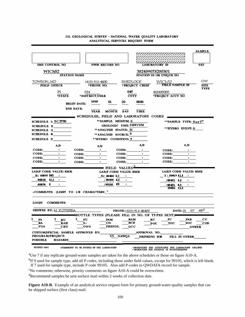
aUse 7 if any replicate ground-water samples are taken for the above schedules or those on figure A10-A.bIf 9 used for sample type, add all P codes, including those under field values, except for 99105, which is left blank.If 7 used for sample type, include P code 99105. Also add P-codes to QWDATA record for sample.
cNo comments; otherwise, priority comments on figure A10-A could be overwritten.dRecommend samples be sent surface mail within 2 weeks of collection date.
Figure A10-B. Example of an analytical service request form for primary ground-water-quality samples that canbe shipped surface (first class) mail.
100

aAdd P codes noted above to form and to QADATA record for this sample.bThis is a priority message, must appear.cOvernight shipping with primary samples (fig. A10-A) is recommended.
Figure A11-A. Example of an analytical service request form for replicate ground-water-quality samples(including radon) that require overnight shipping.
101

aAdd P codes noted above to form and to QADATA record for this sample.bNo comments; otherwise, priority comments on figure A11-A could be overwritten.cSurface (first-class) shipping with primary samples (fig. A10-B) is recommended.
Figure A11-B. Example of an analytical service request form for replicate ground-water-quality samples thatcan be shipped surface (first class) mail.
102

aUse indicated spiked-sample P codes; include in QADATA record for sample.bInclude lot number of each spike vial used with each schedule.cShip overnight with primary unspiked (background) ground-water samples (fig. A10-A).
Figure A12-A. Example of an analytical service request form for replicate field-spiked, ground-water samplesfor pesticides and volatile organic compounds; first set, TIME: HH:02.
103

aUse indicated spiked-sample P codes; include in QADATA record for sample.bInclude lot number of each spike vial used with each schedule.cShip overnight with primary unspiked (background) ground-water samples (fig. A10-A).
Figure A12-B. Example of an analytical service request form for replicate field-spiked, ground-water samplesfor pesticides and volatile organic compounds; second set, TIME: HH:03. (If optional third set is taken, use athird form similar to the one above but with TIME: HH:04.)
104

aAdd all P-codes to form and to QADATA record for sample.bPriority comment, blank water lot number. If SC2090 not taken, NWQL pesticide-free blank water can beused, and if it is used, change the P code 99100 to “40” and the comment to “NWQL PBW: lot no.”cShip blank samples with corresponding ground-water-quality samples.
Figure A13-A. Example of an analytical service request form for field blanks that require National WaterQuality Laboratory blank waterand overnight shipping.
105

aAdd all P codes to form and to QADATA record for this sample.bPriority comment, must appear.cRecommend field-blank samples be shipped surface mail with corresponding ground-water samples(see figs. A10-A,B).
Figure A13-B. Example of an analytical service request form for field blanks that require Quality of WaterService Unit inorganic-free blank water (QWSU-IBW)and surface mail shipping.
106
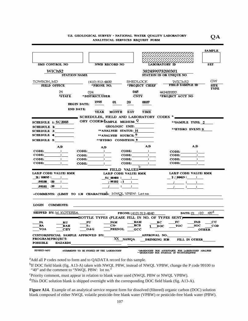
aAdd all P codes noted to form and to QADATA record for this sample.bIf DOC field blank (fig. A13-A) taken with NWQL PBW, instead of NWQL VPBW, change the P code 99100 to“40” and the comment to “NWQL PBW: lot no.”
cPriority comment, must appear in relation to blank water used (NWQL PBW or NWQL VPBW).dThis DOC solution blank is shipped overnight with the corresponding DOC field blank (fig. A13-A).
Figure A14. Example of an analytical service request form for dissolved (filtered) organic carbon (DOC) solutionblank composed of either NWQL volatile pesticide-free blank water (VPBW) or pesticide-free blank water (PBW).
107
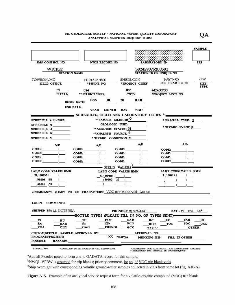
aAdd all P codes noted to form and to QADATA record for this sample.bNWQL VPBW isassumed for trip blanks; priority comment,lot no.of VOC trip blank vials.cShip overnight with corresponding volatile ground-water samples collected in vials from same lot (fig. A10-A).
Figure A15. Example of an analytical service request form for a volatile-organic-compound (VOC) trip blank.
108

aAdd all P codes noted to form and to QADATA record for this sample.bIf a replicate trace-element sample is collected (fig. A17), code sample type as 7; otherwise, code as 9.cAdd labcodes for arsenic (LC0112) and selenium (LC0087).dInclude field measurements (median values), particularly for specific electrical conductance (SC) at 25 degreesCelsius (P code 00095), and note on comment line if SC exceeds 2,000.
eRecommend sample be shipped surface mail with other primary inorganic samples (see fig. A10-B).fOnly the FA sample bottle is required if Study Unit acidifies sample, provides field SC value, and indicates incomment field if SC exceeds 2,000 microsiemens per centimeter at 25 degrees Celsius.
Figure A16. Example of an analytical service request form for a primary trace-element ground-water sample(SC2703).
109

aAdd all P codes noted to form and to QADATA record for this sample.bAdd labcodes for arsenic (LC0112) and selenium (LC0087).cInclude field measurements (median values), particularly for specific electrical conductance (SC) at 25 degreesCelsius (P code 00095), and note on comment line if SC exceeds 2,000.
dRecommend sample be shipped surface mail with other primary inorganic samples (see fig. A10-B).eOnly the FA sample bottle is required if Study Unit acidifies sample, provides field SC value, and indicates incomment field if SC exceeds 2,000 microsiemens per centimeter at 25 degrees Celsius.
Figure A17. Example of an analytical service request form for a replicate trace-element ground-water sample(SC2703).
110
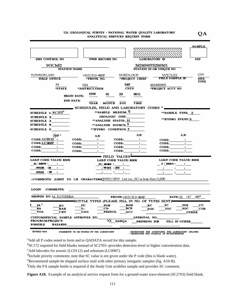
aAdd all P codes noted to form and to QADATA record for this sample.bSC172 required for field blanks instead of SC2703--provides detection-level or higher concentration data.cAdd labcodes for arsenic (LC0112) and selenium (LC0087).dInclude priority comments; note that SC value is not given under the P code (this is blank water).eRecommend sample be shipped surface mail with other primary inorganic samples (fig. A10-B).fOnly the FA sample bottle is required if the Study Unit acidifies sample and provides SC comment.
Figure A18. Example of an analytical service request form for a ground-water trace-element (SC2703) field blank.
111

aAdd all P codes noted to form and to QADATA record for this sample.bAdd labcodes for arsenic (LC0112) and selenium (LC0087).cInclude priority comments; note that SC value is not given under the P code (this is blank water). Specifybottle codeoriginally foundonbottleasreceivedfrom BTD&QS.
dRecommend sample be shipped surface mail with other primary inorganic samples (fig. A10-B).eOnly the FA sample bottle is required if the Study Unit acidifies sample and provides the SC comment.
Figure A19. Example of an analytical service request form for a standard-reference trace-element (SC2703)sample for ground water.
112

LOGIN REPLY SHEET
Date Mailed: __________________ Person sending shipment: ______________________
Place from which shipment was mailed: ___________________________________
Shipped via: _________________________________________________________
Type of Sample (circle one): ORG NUT PEST VOC RADON INORG
Station Numbers of Samples in This Shipment
____________________________________ __________________________________
____________________________________ __________________________________
____________________________________ __________________________________
____________________________________ __________________________________
____________________________________ __________________________________
LOGIN STAFF:Please enter the following information on this form and mail the form back to us with the attached
self-addressed, franked envelope. Note that there is an 8-ounce bottle of tap water in this shipment marked“TEMPERATURE” for use in measuring water temperature.
Person logging in shipment: ________________________________________
Date Shipment Arrived:
Water Temperature:
Comments (if applicable):
If you have any questions about this shipment, please contact:
Name: _________________________________________
Telephone: ( ) __________ - _______________
E-mail or Internet: _______________________________
Thank You For Your Participation in This Quality Assurance Program.
Figure A20. Example of Study Unit login reply form sent with samples shipped by overnightmail.
113

Errata for Open-File Report 95-399
Corrections are by Michael Koterba; January 24, 1996
Page 16, Table 3, Footnote 21, Item (1)--change from:
"For assistance with (1) isotope, radiochemical, and other specialized equipment, contact the NAWQA QualityAssurance Specialist;"
to:
"For assistance with (1) deuterium-oxygen isotopes, and quality-assured sample bottles and caps for theseisotopes, contact Tyler Coplen, Isotope Fractionation, USGS National Research Program, MS 431, Reston, Va.(via [email protected]); for assistance with tritium isotopes, and quality-assured sample bottles and caps for theseisotopes, contact Robert Michel, Isotope Tracers, MS 434, USGS National Research Program, Menlo Park, Calif. ([email protected]);"
Page 66, Table 21, 3. Other Samples--Columns for Tritium isotopes and Deuterium-Oxygen isotopeschangefrom:
.
Team Member A
Sample type (SC, LC)and order of collection
Collect, byfilling
Quality-assurancechecks or measures
• Tritium isotopes 1, 1.0-L, clear, prerinsed polybottle, filled to top after 3,25-mL rinses (include capwith conical insert)
Verify DIW is still in bottle from
office prerinse before use, other-wise replace bottle. Leave noheadspace in bottle
• Deuterium-Oxygen isotopes
1, 125-ml, glass, amberbottle to top after 3, 25-mlrinses (include cap withconical insert)
Leave no headspace in bottle
to:
Team Member A
Sample type (SC, LC)and order of collection
Collect, byfilling
Quality-assurancechecks or measures
• Tritium isotopes 1, 1.0-L, dry, high-density-poly (preferred) or glassbottle, without prerinsing,until it overflows, and sealwith a cap with conical insert
To reduce breakage of glassbottles caused by samples freez-ing during shipment, pour outsample until the water level is atthe bottle shoulder seam.
• Deuterium-Oxygen isotopes
1, 60-mL, dry, clear, glass(preferred) or poly bottle,without prerinsing, until itoverflows, and seal with a capwith conical insert
To reduce breakage of glassbottles caused by samples freez-ing during shipment, pour outsample until the water level is atthe bottle shoulder seam. Sam-ples collected in poly bottles aresent immediately for analysis,and are unsuitable for archiving.