ground monitoring system fault investigation north ... papers/0517_ground_monitoring_fault...ground...
TRANSCRIPT

Ground Monitoring System Fault Investigation North Antelope Rochelle Mine
Lyle Hunt / Scott Svoboda - Peabody EnergyDavid Shipp / Mike Peters - Eaton Electrical Engineering Services
WMEA Spring ConferenceDenver, CO May 31, 2017
Photo of NARM site here?

Background, Mine
• 2 Mines Combined
• 22-24 Trains/Day
• Low Sulphur Coal
• Supplies Generation Industry
• 250T / 400T Trucks
• 13,000,000 lbs. Excavator
• Preceding Week – Multiple Ground Faults (6) / GF Tripping
• Arc Flash Event Involving Ground and Personnel

General Background on NARM
• The North Antelope Rochelle Mine is the world’s largest
coal mine. The mine sold nearly 93 million tons of
compliance coal during 2016 and more than 2 billion
tons since the mine began.
• The complex uses 4 draglines and 15 shovels.
• Coal is currently delivered to more than 60 electricity
generating customers throughout the United States.
• The complex currently has a workforce of approximately
1,145 people and annually injects approximately $2.3
billion into the regional economy in direct and indirect
benefits.

Ground Fault Event
• On 2/8/16 there was a low level arc flash event at NARM on a stationary substation (PS34). 69 kV to 22.9 kV
• Sub was immediately removed from service
• Root Cause – DCS – Gary Sorenson
• Bruno Engineering – Confirmed RCA
• WESCO –
• Eaton Engineering – Grounding Expert – David Shipp

PS-34 Function
• 69kV / 22.9 kV Sub
• 15 MVA Txmr
• 25 Amp NGR
• 2 Ground Mats
• Grounding Conductor Monitor
• NGR Integrity Relay
• Feeds Excavator

Ground Fault Event
• Trouble-shooting GrdFault
• Reclosed Breaker
• Grd Monitor Relay / Control Panel Failed on Reclosing
• Low Level Arc Flash Occurred. Approx. 1.2 Calorie Event

Ground Fault Event

Investigation; Involved Ground Mats
• On-Site Investigation
• Lightning?
• Installation Errors?
• MSHA Requirements
• Transferred Earth Potentials
• Transient Over Voltages
• Earth Megger Meas.
• Tripping Data
• Open Neutral in Txmr / NGR

MSHA Requirements at PS34
• Protect Personnel• Protect Equipment• A Mine System is not an Industrial Plant!• MSHA Design
– Involves Transferred Earth Potentials– “Transfer by Grounded Conductor”– 2 Ground Mats (+Safety Ground Mat/Borehole Grd
Mat/Isolation Grd Mat)– 100V GF Touch / Step Potential Max at Shovel– (25A)(4 ohms Max in Trailing Cable Ground Conductor) =
100V– MSHA Required Protection

Mining Installation - Without
Safety Ground Bed – Xfer by
Grded Conductor
∆ Eg = Vman = GMR = IgZm
Remote Earth
∆ Eg

Mining Installation - With Safety
Ground Mat – Xfer to Safety Ground Mat – not to
the Man
Remote Earth
∆ Eg
∆ Eg = GMR = IgZm≠ Vman

Mining Installation - With Safety
Ground Mat – Grd Fault at Shovel – Vman = 100V
Max
Remote Earth
∆ Eg = Igf(Zgc) < 100V= Vgc drop = Vman
∆ Eg
Vmax = Vlg = Vng
Igf

On-Site Investigation
• NGR Monitor Cable Arced to control cables and Sub Frame Ground
• GC Monitor Failed / Arced to Sub Frame Ground
• Zm1 = Zm-sub = 0.68 ohms
• Zm2 = Zs-gm = 1.86 ohms
• Zm1-m2 = 2.24 ohms
• NGR = 528 ohms (no open Neutrals)
• All Grounds Installed Correctly
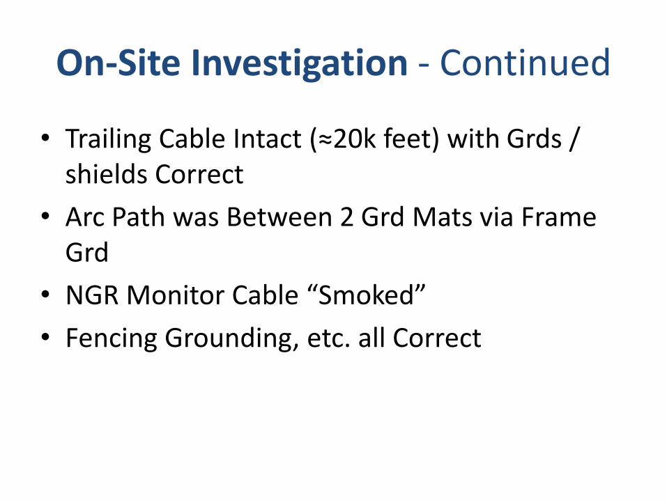
On-Site Investigation - Continued
• Trailing Cable Intact (≈20k feet) with Grds / shields Correct
• Arc Path was Between 2 Grd Mats via Frame Grd
• NGR Monitor Cable “Smoked”
• Fencing Grounding, etc. all Correct
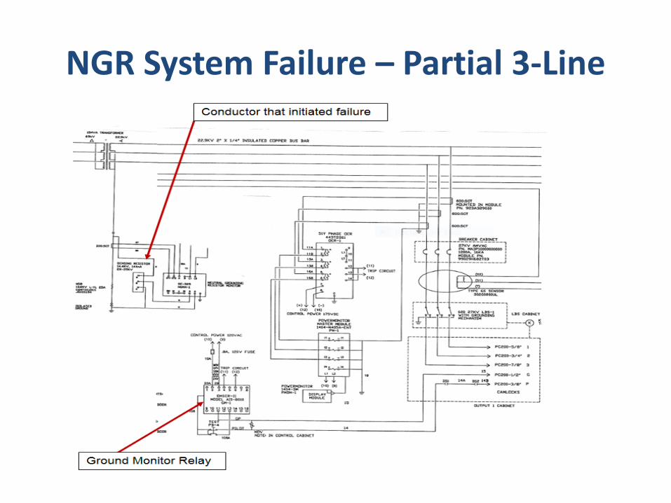
NGR System Failure – Partial 3-Line

NGR Monitor Cable Failure –“Smoked”
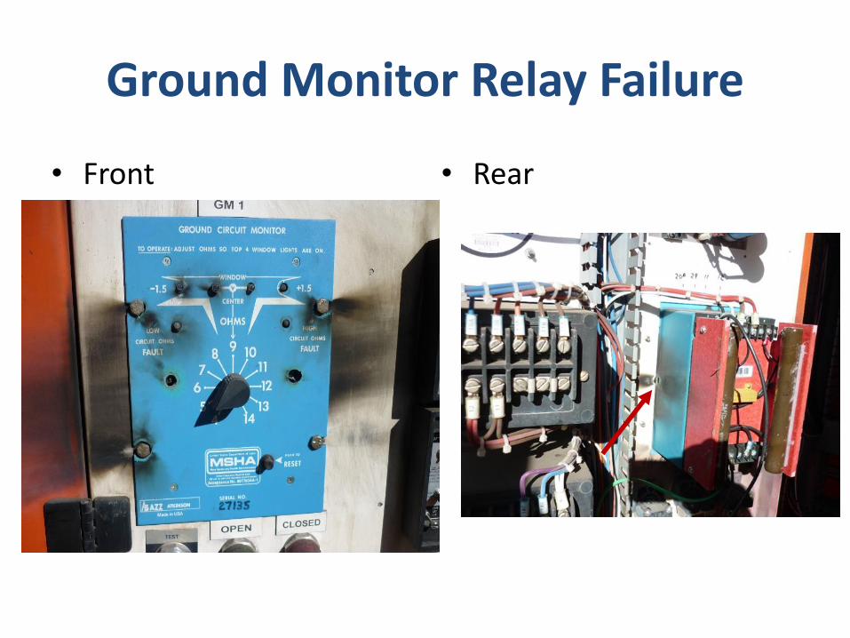
Ground Monitor Relay Failure
• Front • Rear

Grd Conductor Monitor – Arced Thru Hinges to Main Sub Grd (Grded
Frame)• Arced Thru Hinges to Main Sub Ground

Substation Ground Design

Failure Analysis – Investigated Everything that
Could Cause This Type of Failure
• Open neutral in Txmr / NGR
• Open circuit ground wire to excavator
• Loose connections
• 1 or both ground mat issues – such as too high of ohmic values
• Open ground wire to safety ground mat
• Excessive length of trailing cable (too much cable capacitance).
• Lightning strikes
• Improperly grounded lightning arresters
• Too much or too little ohms between the 2 ground mats.
• Wire routing?
• Path for current to flow bypassing neutral grounding resistor (NGR)

Failure Analysis – Investigated Trailing Cable Lengths
• All Items in Black Were Found to be Correct (NGR, Txmr, Basic MSHA Required Components, etc.). Red were Found Deficient
• Transient Over Voltages Due to Arcing Grd Fault
– If Capacitive Charging Current (thru Insulation to grd) > Resistive Grd Fault Current, then Voltages can Escalate with Respect to Grd. About 700%V Burns into Massive fault.
– Icapac = Ingr at 24.3k feet – still within limits at 20K ft

Failure Analysis – Wire Routing• NGR Monitor Wire
• Under GF, Vng Estimated to be between 6 kV and 13.2 kV (input to monitor voltage divider).
• This Wire entered Substation Instrument Room and was Tie Wrapped to the Control Wires for lights, etc. (MV wire tie wrapped to LV control Wires)
• When NGR Monitor relay was removed, this MV wire was not completely removed. – This Conductor was involved to substation Grd Mat

Failure Analysis – NGR Bypassed
• GC Monitor Relay Indicated High Current arced thru it to Sub Grd
• NGR Monitor is Tied to Safety Grd Mat but Physically Installed on Substation Grded Steel.
• NGR Monitor also Mounted on Sub Steel but ties to Txmr N point and to Safety Grd Mat.
• Both Relays Will Have Substantial voltages Across them Under GF Conditions (Between 2 Grd Mats)

Step 1 - Ground Fault Path; Then Arcs
thru NGR Monitor Wire to Sub Grd Mat – Vng 6.3 to 13.2 kV

Step 2; Current Bypasses NGR thru Zm1-m2; ∆Eg now across GC Monitor

Step 2; ∆Eg Exceeds GC Monitor Limits
• ∆Eg Estimated at 2240V+
• MOV Fails
• GF Current Estimated at 1000A’s +/-
• GFCT Saturates and GF Relay never Operates.
• Relay Fails Internally

Step 3: Ground Monitor Relay Failure

Step 3: Ground Monitor Relay Failure
• Fault Path Bypasses Zm1-m2 (2.24 ohms)
• Current Increases greater than 1800A’s
• Phase Instantaneous (device 50) trips (phase CTs do not saturate)
• Arc Blast from around GC Monitor Engulfs Personnel in Close Proximity Causing Arc Flash Incident

Conclusions
• Failure was Initiated by Wire Routing
• Initial Failure Allowed NGR to be Bypassed
• High Fault Current Resulted in CT Saturation / No GF Tripping
• Sustained and/or Repeated Voltages between 2 Ground Mats Caused GC Monitor to Fail Internally.
• Failed GC Monitor now Bypassed Zm1-m2
• Ultimate Arc Flash Condition Occurred with Igf >1800A’s

Recommendations
• ALWAYS separate MV / LV Wiring from Each Other.
• NGR and GC Relays Connect Both Grd Mats Together
• Be Aware that GrdWires between 2 GrdMats Must be Treated as MV
• Investigate Using a PT in Lieu of the Voltage Divider for NGR Monitor
• Redesign Substation Ground Monitoring System. Include Sustained Grd Fault and Lightning Conditions
• Survey other Substations
• Test Ground Mats Yearly

Solution
• Redesign substation ground monitoring system to prevent / improve personnel and safety and prevent recurrence of ground fault event.1. Maintain the system grounding integrity
a. Yearly Inspection of entire system (offline)
b. Insure best practices are used in setting up system.
c. Develop SOP’s on how to maintain system/install grounding system.
d. Monthly Testing of Protection functions
2. Educate Employees how to Maintain system and why.
3. Develop recommendations to minimize exposure to personnel

THANK YOU
ANY QUESTIONS??