grit collection & classification case studies · grit collection & classification case...
TRANSCRIPT
Grit Collection & Classification Case
Studies
OWEA2010 Specialty Biosolids Specialty
Workshop
Brian F. McNamara, HRSD
Definition of Grit
Metcalf & Eddy 2nd Edition 1979
“…grit, consisting of sand, gravel, cinders, or other heavy solid materials that have subsiding velocities or specific gravities substantially greater than those of the organic putrescible solids,… Grit also includes eggshells, bone chips, seeds, coffee grounds, and large organic particles, such as food waste.”
Grit Design Parameters
Grit Removal Equipment is designed for 2.65 SG and 1 fps horizontal velocities**
Collection systems design velocities for 2 fps peak diurnal flow.
Velocity for grit re-suspension is ~ 5.0 fps
** Metcalf & Eddy 2nd Edition 1979
Notes that if the native grit specific gravity is less than 2.65, then grit removal equipment designs should be adjusted accordingly or less than 1 ft/sec horizontal velocity.
Operator View of Grit
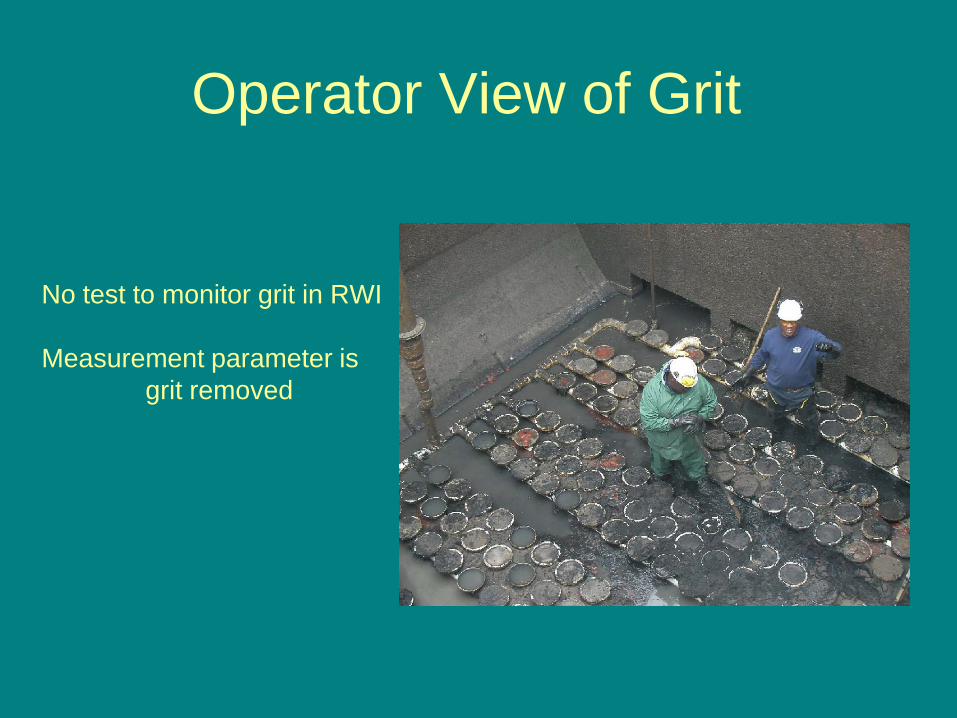
No test to monitor grit in RWI
Measurement parameter isgrit removed
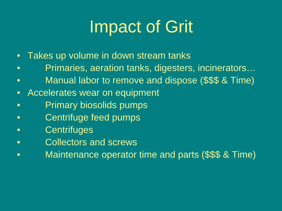
Impact of Grit• Takes up volume in down stream tanks• Primaries, aeration tanks, digesters, incinerators…• Manual labor to remove and dispose ($$$ & Time)• Accelerates wear on equipment• Primary biosolids pumps• Centrifuge feed pumps• Centrifuges• Collectors and screws• Maintenance operator time and parts ($$$ & Time)
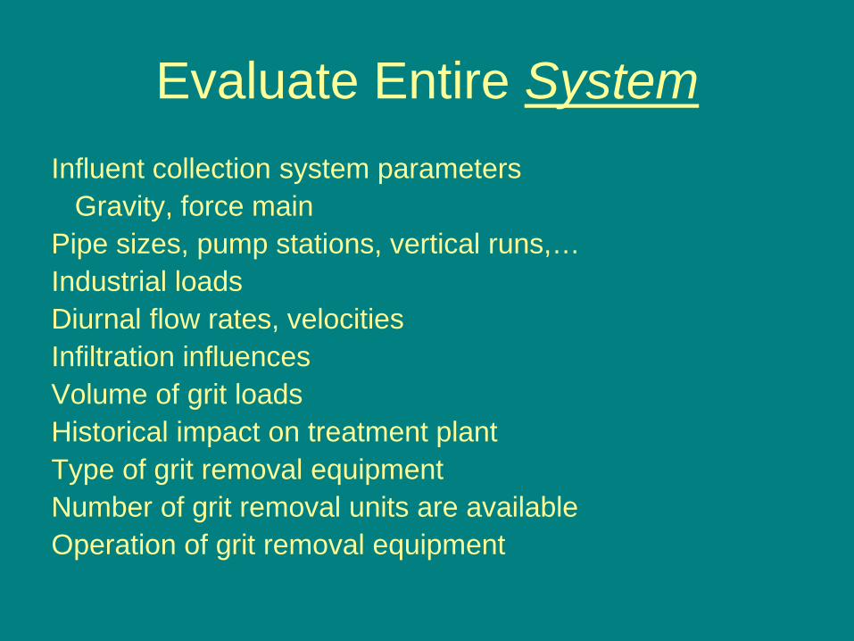
Evaluate Entire SystemInfluent collection system parameters
Gravity, force mainPipe sizes, pump stations, vertical runs,…Industrial loadsDiurnal flow rates, velocitiesInfiltration influencesVolume of grit loadsHistorical impact on treatment plantType of grit removal equipmentNumber of grit removal units are availableOperation of grit removal equipment
How to…?• How to sample grit?• How to analyze grit?• How to quantify?• How to conduct a process review?• How to conduct an equipment
review?• How to find historical effect of grit
on treatment processes?
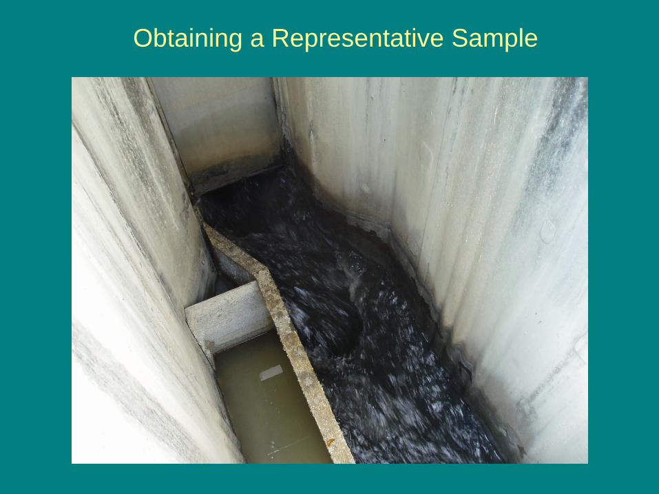
Obtaining a Representative Sample
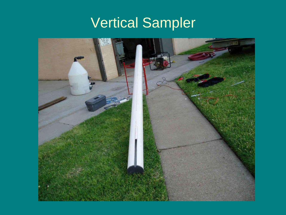
Vertical Sampler
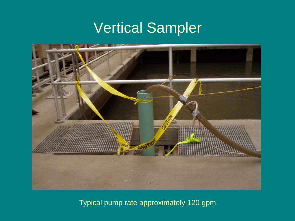
Vertical Sampler
Typical pump rate approximately 120 gpm
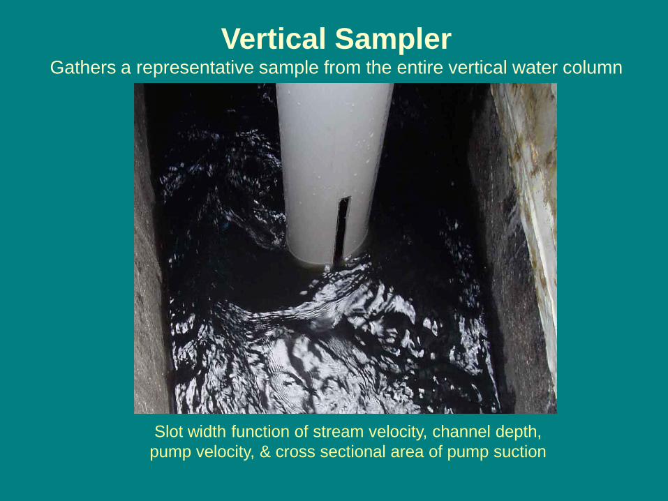
Vertical SamplerGathers a representative sample from the entire vertical water column
Slot width function of stream velocity, channel depth, pump velocity, & cross sectional area of pump suction
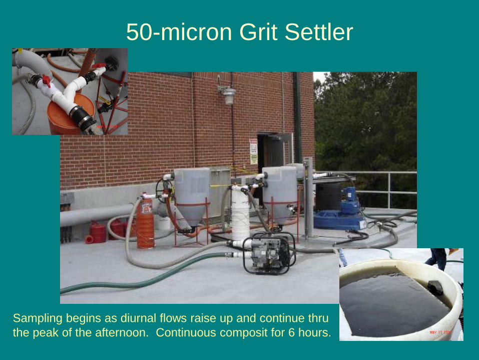
50-micron Grit Settler
Sampling begins as diurnal flows raise up and continue thru the peak of the afternoon. Continuous composit for 6 hours.
Post-Sampling Activities
• Decant sample from settler• Rinse loose floatable organics from
sample• Drain off liquid • Volume & Weight of total sample
recorded• Wet-sieve
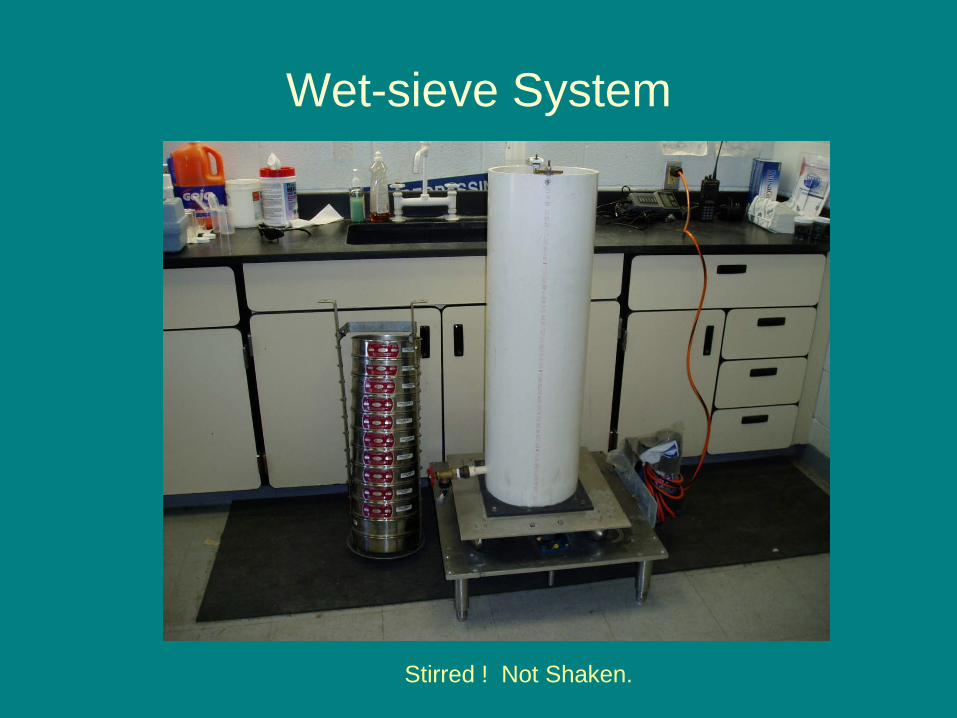
Wet-sieve System
Stirred ! Not Shaken.
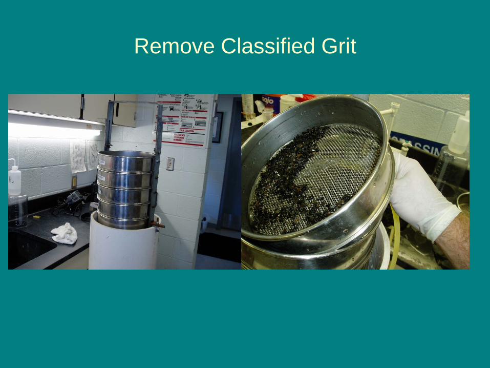
Remove Classified Grit
Laboratory Analysis & Calculations
Fixed Solids Determination
Flow weighted calculations for quantity of grit per MGD
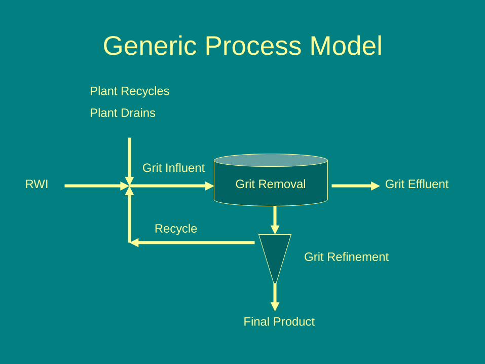
Generic Process Model
Grit Removal Grit Effluent
Grit Refinement
Final Product
RWI
Plant Recycles
Plant Drains
Grit Influent
Recycle
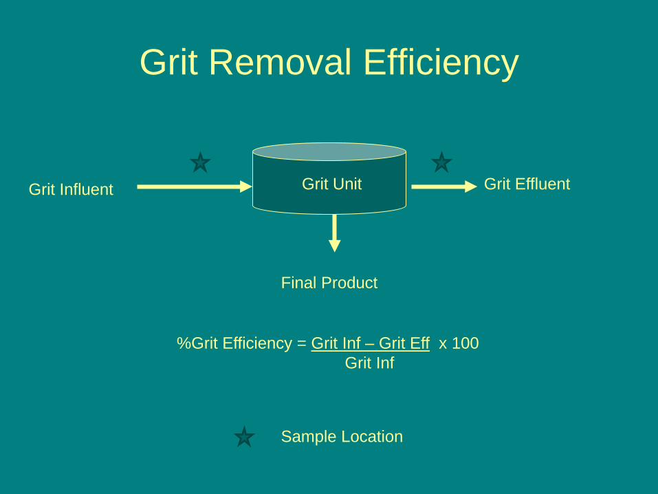
Grit Removal Efficiency
Grit Unit Grit Effluent
Final Product
Grit Influent
Sample Location
%Grit Efficiency = Grit Inf – Grit Eff x 100Grit Inf
Grit vs. Grit
Pilot Evaluation Comparing Two Grit Removal Technologies
Brian F. McNamara, Thomas Kochaba, Jimmie Griffiths, David Book
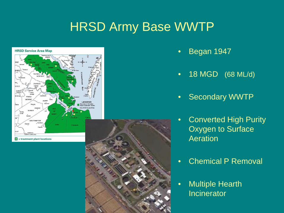
HRSD Army Base WWTP
• Began 1947
• 18 MGD (68 ML/d)
• Secondary WWTP
• Converted High Purity Oxygen to Surface Aeration
• Chemical P Removal
• Multiple Hearth Incinerator
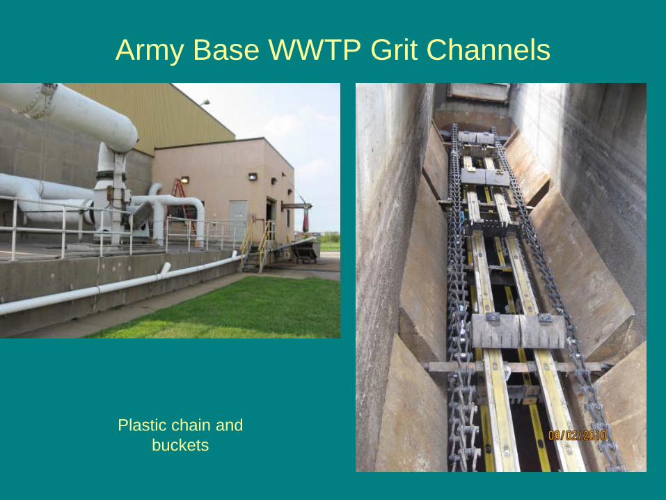
Army Base WWTP Grit Channels
Plastic chain and buckets
Army Base WWTP
• Present: Grit Channels
– Inefficient system, cannot handle slug loads
• Consequences– Increased wear on primary biosolids pumps– Grit removed from aeration tanks– Grit removed from holding tank
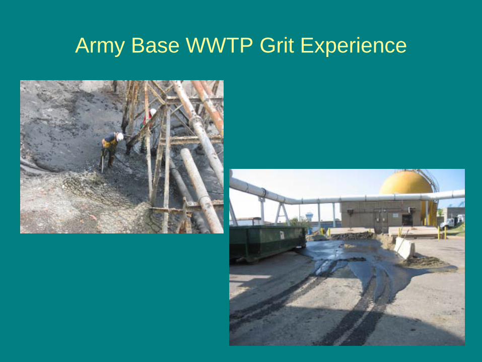
Army Base WWTP Grit Experience
2010 Plant Improvement
• 18 MGD (68 ML/d)• Five Stage Bardenpho
– Methanol Addition• Distributive Control System• Nitrification Enhancement Facility• New Pretreatment Headworks
– Ban Screens– Self Cleaning Wetwell– Grit Removal???
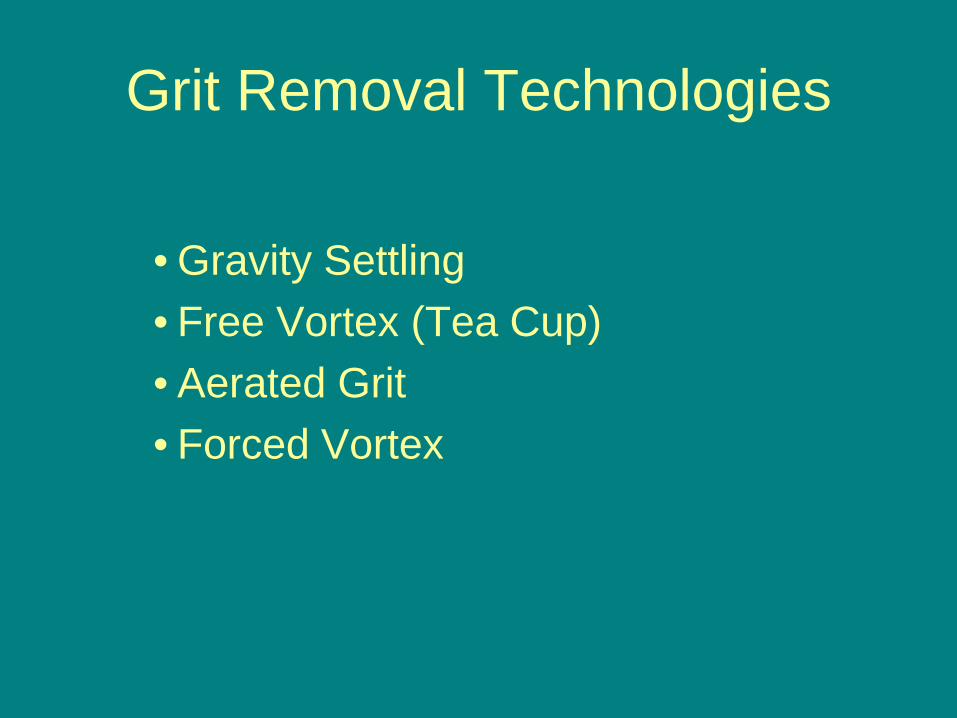
Grit Removal Technologies
• Gravity Settling• Free Vortex (Tea Cup)• Aerated Grit• Forced Vortex
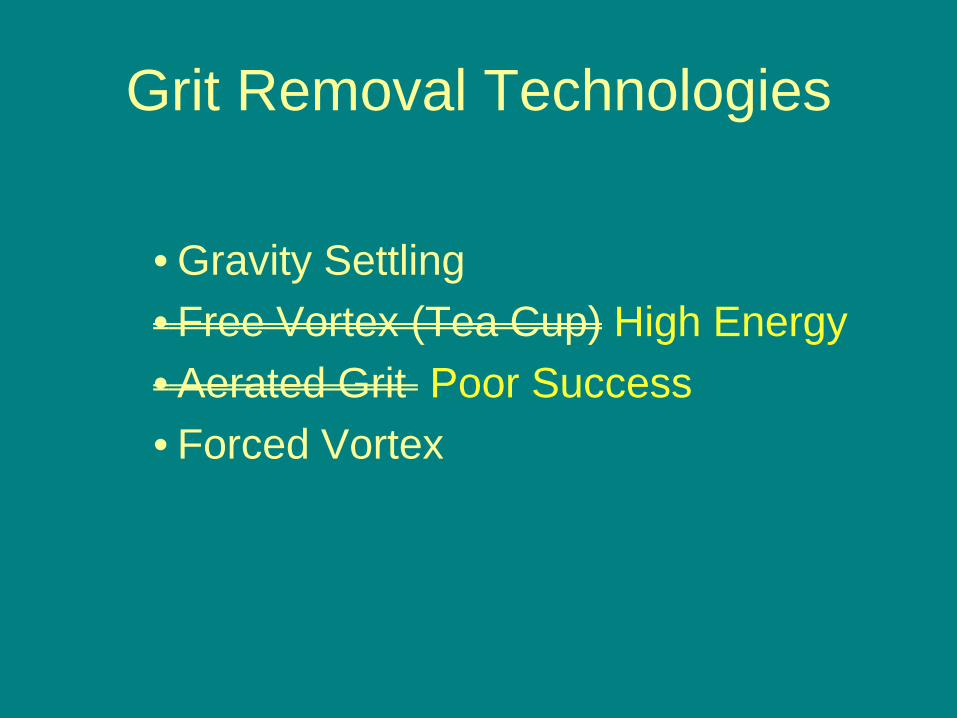
Grit Removal Technologies
• Gravity Settling• Free Vortex (Tea Cup) High Energy• Aerated Grit Poor Success• Forced Vortex
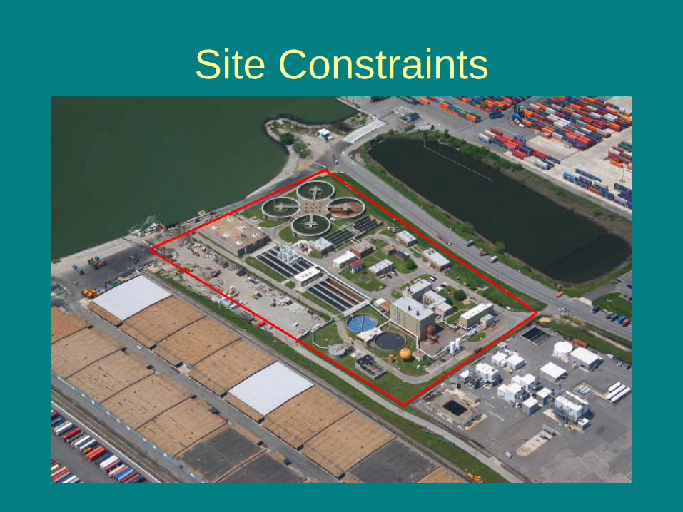
Site Constraints
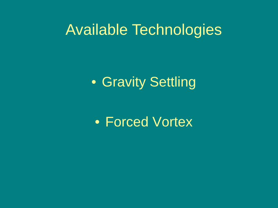
• Gravity Settling
• Forced Vortex
Available Technologies
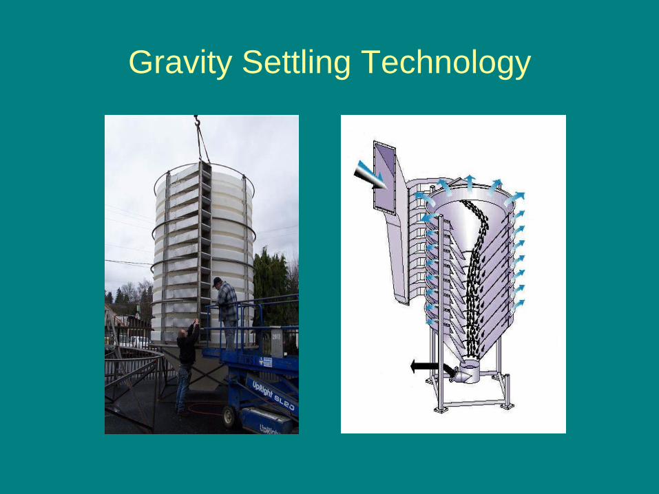
Gravity Settling Technology
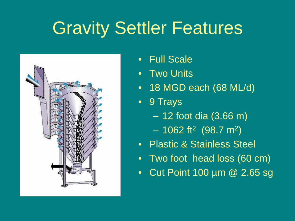
Gravity Settler Features• Full Scale• Two Units• 18 MGD each (68 ML/d)• 9 Trays
– 12 foot dia (3.66 m)– 1062 ft2 (98.7 m2)
• Plastic & Stainless Steel• Two foot head loss (60 cm)• Cut Point 100 µm @ 2.65 sg
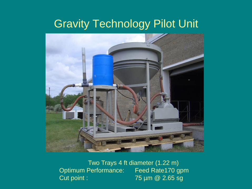
Gravity Technology Pilot Unit
Two Trays 4 ft diameter (1.22 m)Optimum Performance: Feed Rate170 gpm Cut point : 75 µm @ 2.65 sg
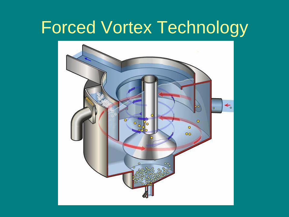
Forced Vortex Technology
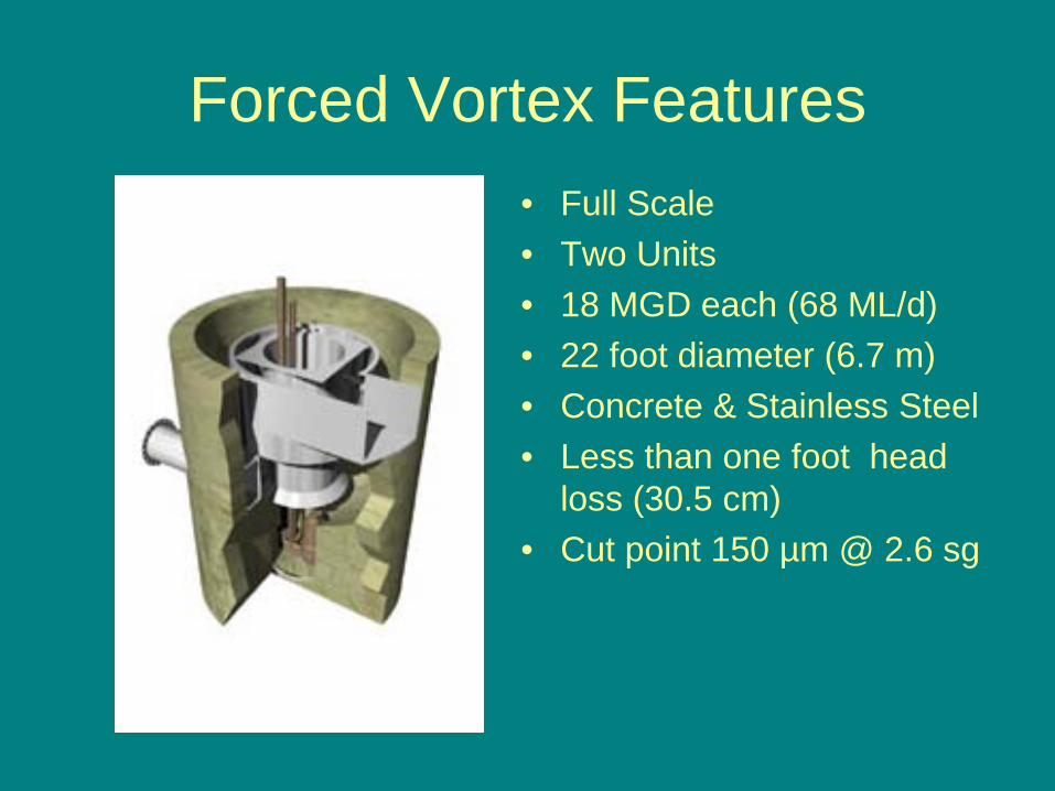
Forced Vortex Features• Full Scale• Two Units• 18 MGD each (68 ML/d)• 22 foot diameter (6.7 m)• Concrete & Stainless Steel• Less than one foot head
loss (30.5 cm)• Cut point 150 µm @ 2.6 sg
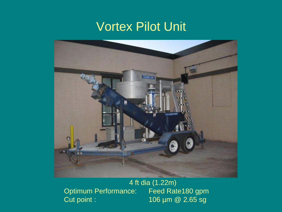
Vortex Pilot Unit
4 ft dia (1.22m)Optimum Performance: Feed Rate180 gpm Cut point : 106 µm @ 2.65 sg
Test Protocol
• Simultaneous Parallel testing• Same day testing• Use native grit from plant RWI• Comparable flow rates• Applicable full scale flow rates• Same test procedures• Same analysis• One laboratory
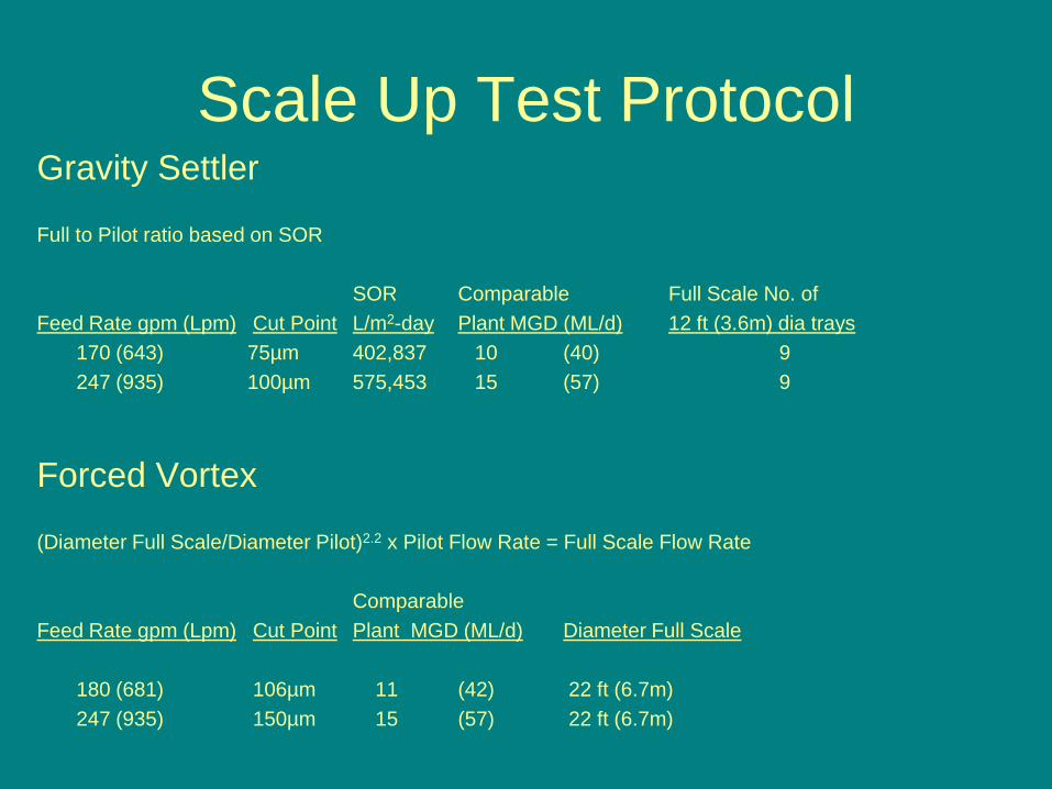
Scale Up Test ProtocolGravity Settler
Full to Pilot ratio based on SOR
SOR Comparable Full Scale No. ofFeed Rate gpm (Lpm) Cut Point L/m2-day Plant MGD (ML/d) 12 ft (3.6m) dia trays
170 (643) 75µm 402,837 10 (40) 9247 (935) 100µm 575,453 15 (57) 9
Forced Vortex
(Diameter Full Scale/Diameter Pilot)2.2 x Pilot Flow Rate = Full Scale Flow Rate
ComparableFeed Rate gpm (Lpm) Cut Point Plant MGD (ML/d) Diameter Full Scale
180 (681) 106µm 11 (42) 22 ft (6.7m)247 (935) 150µm 15 (57) 22 ft (6.7m)
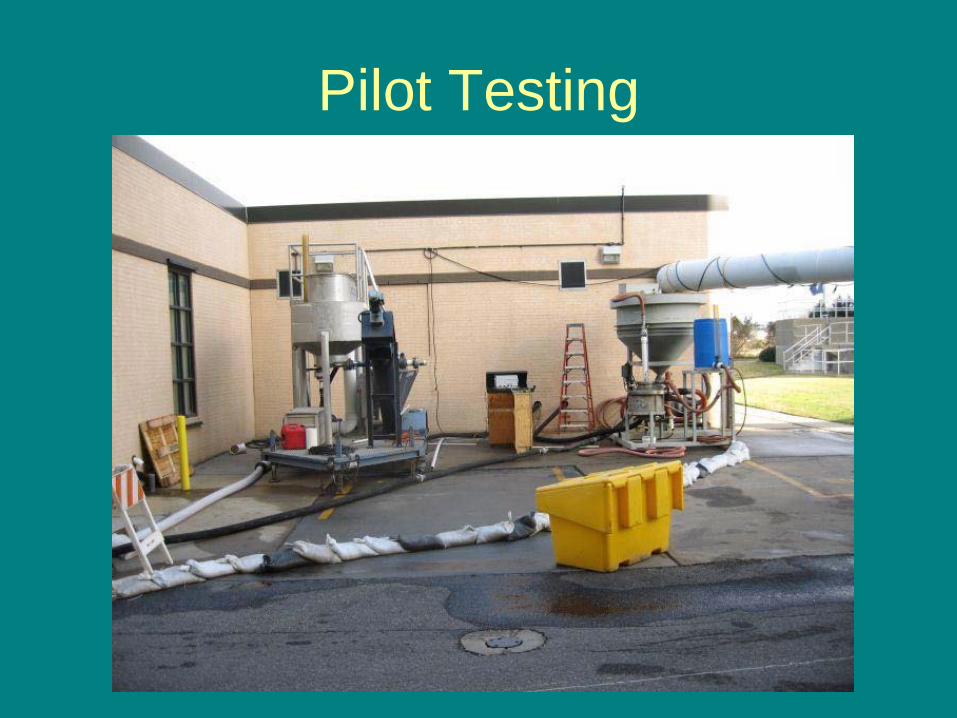
Pilot Testing
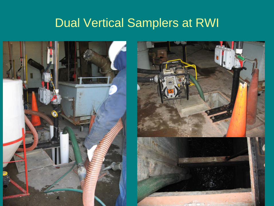
Dual Vertical Samplers at RWI
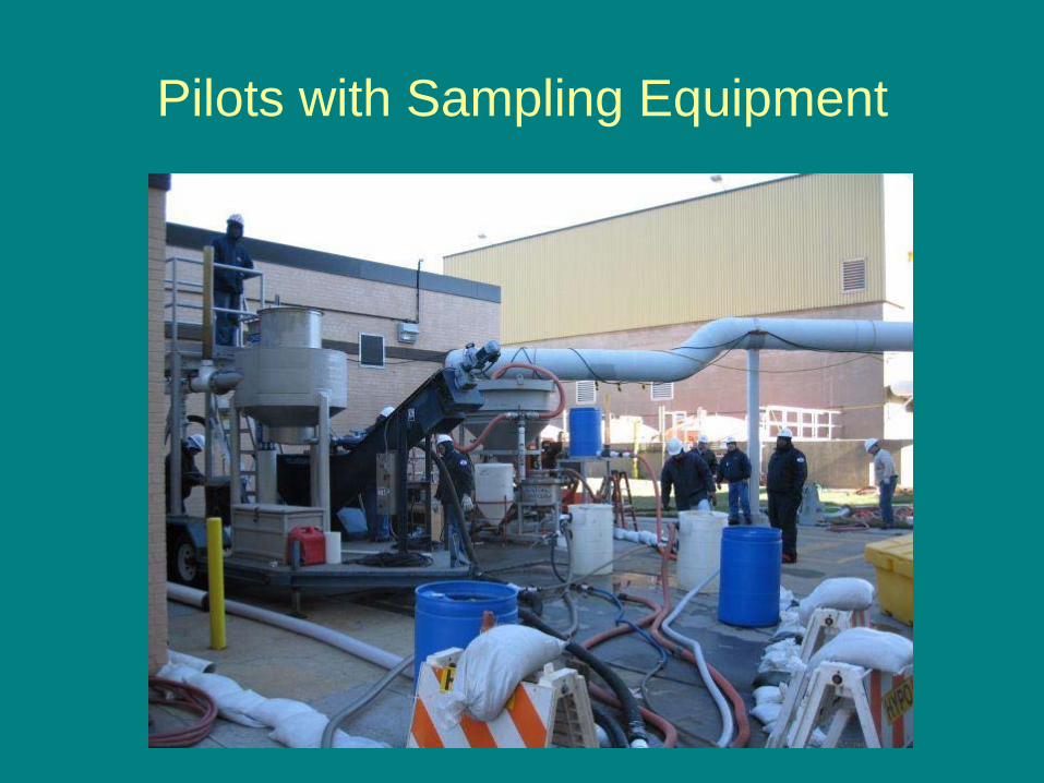
Pilots with Sampling Equipment
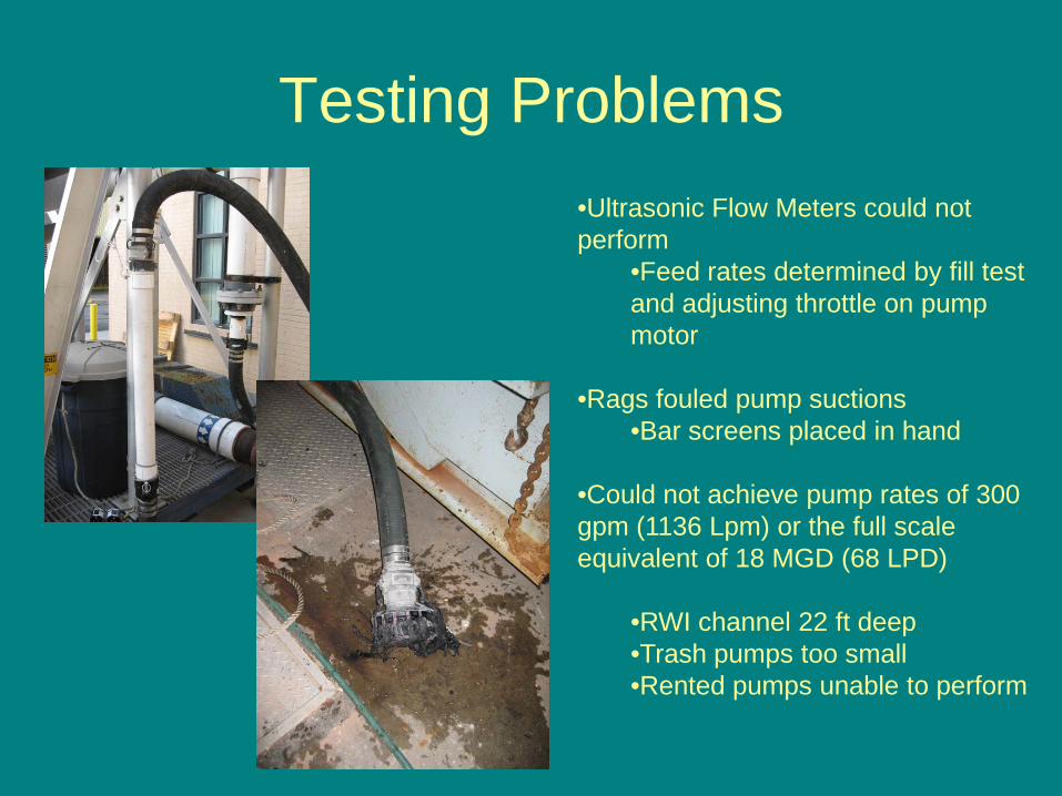
Testing Problems•Ultrasonic Flow Meters could not perform
•Feed rates determined by fill test and adjusting throttle on pump motor
•Rags fouled pump suctions•Bar screens placed in hand
•Could not achieve pump rates of 300 gpm (1136 Lpm) or the full scale equivalent of 18 MGD (68 LPD)
•RWI channel 22 ft deep•Trash pumps too small•Rented pumps unable to perform
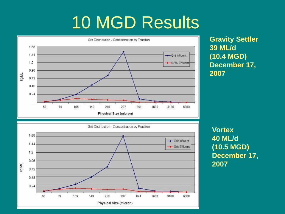
10 MGD ResultsGravity Settler 39 ML/d (10.4 MGD) December 17, 2007
Vortex 40 ML/d (10.5 MGD) December 17, 2007
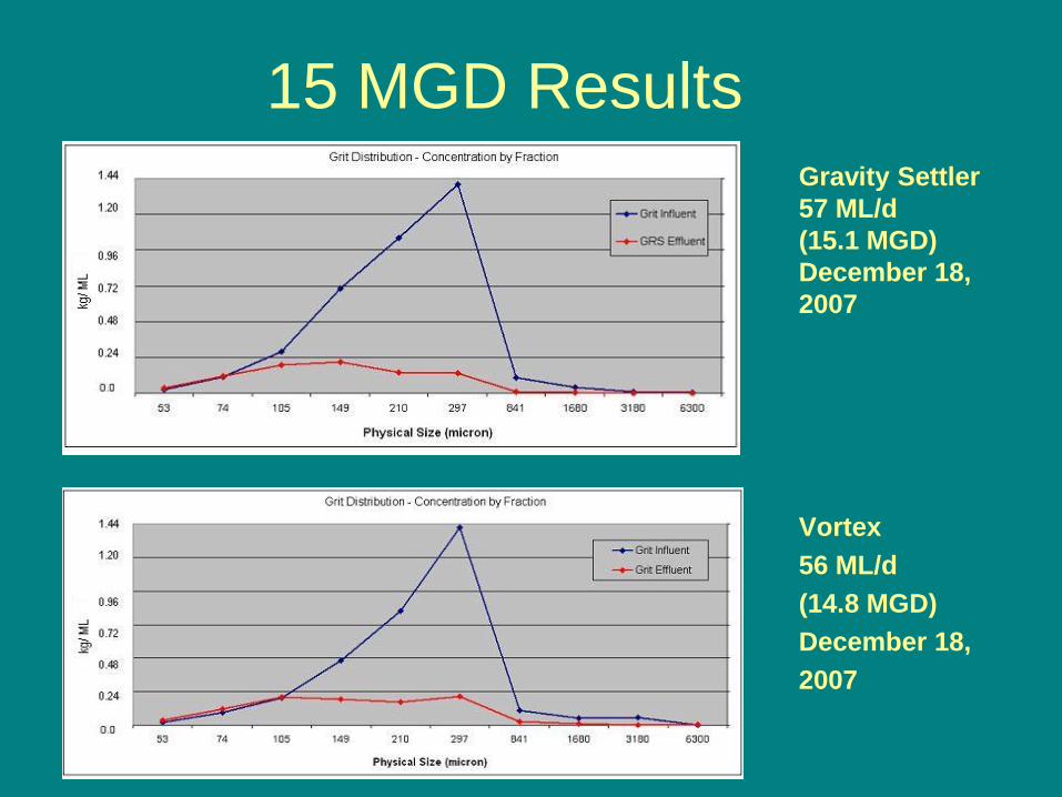
15 MGD Results
Vortex 56 ML/d (14.8 MGD)December 18,2007
Gravity Settler 57 ML/d (15.1 MGD) December 18, 2007
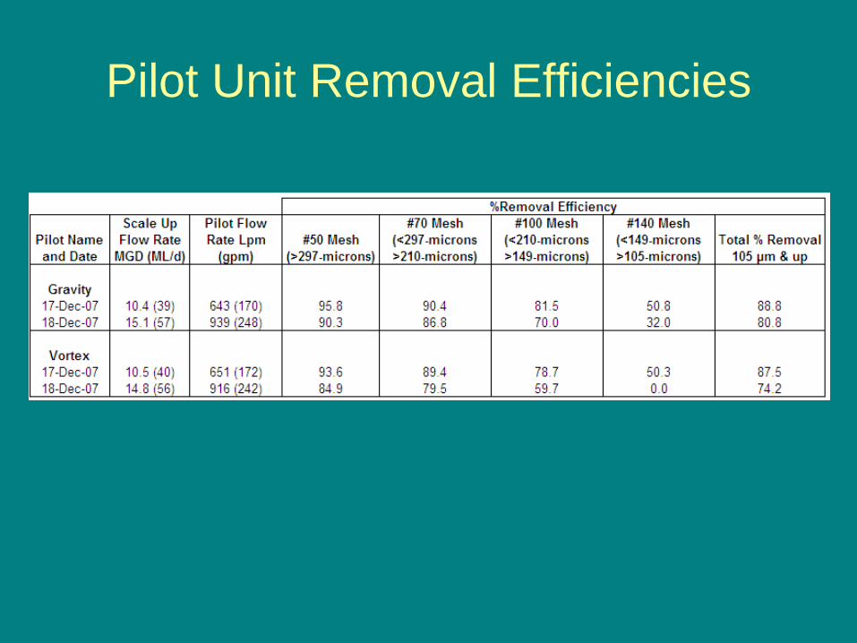
Pilot Unit Removal Efficiencies
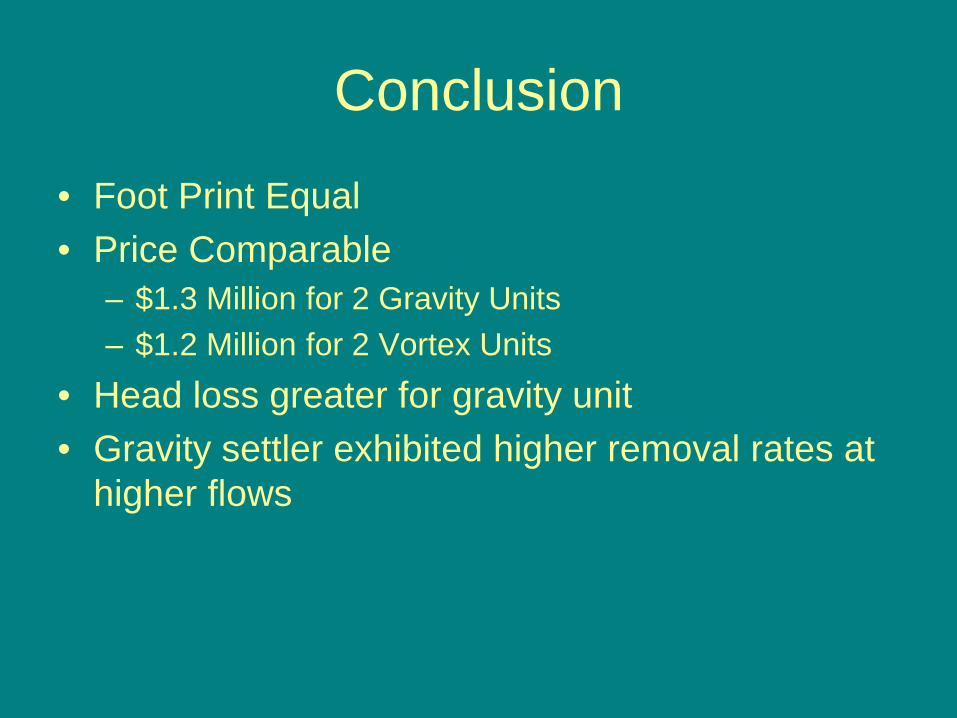
Conclusion
• Foot Print Equal• Price Comparable
– $1.3 Million for 2 Gravity Units– $1.2 Million for 2 Vortex Units
• Head loss greater for gravity unit• Gravity settler exhibited higher removal rates at
higher flows
True Grit
Full-Scale Performance Assessment of Three Common Grit Removal
Technologies
Brian F. McNamara, HRSD
Jimmie Griffiths
Dave Book
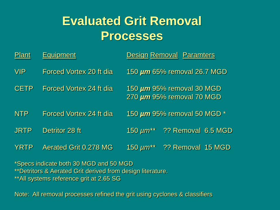
Plant Equipment Design Removal Paramters
VIP Forced Vortex 20 ft dia 150 µm 65% removal 26.7 MGD
CETP Forced Vortex 24 ft dia 150 µm 95% removal 30 MGD270 µm 95% removal 70 MGD
NTP Forced Vortex 24 ft dia 150 µm 95% removal 50 MGD *
JRTP Detritor 28 ft 150 µm** ?? Removal 6.5 MGD
YRTP Aerated Grit 0.278 MG 150 µm** ?? Removal 15 MGD
*Specs indicate both 30 MGD and 50 MGD**Detritors & Aerated Grit derived from design literature. **All systems reference grit at 2.65 SG
Note: All removal processes refined the grit using cyclones & classifiers
Evaluated Grit Removal Processes
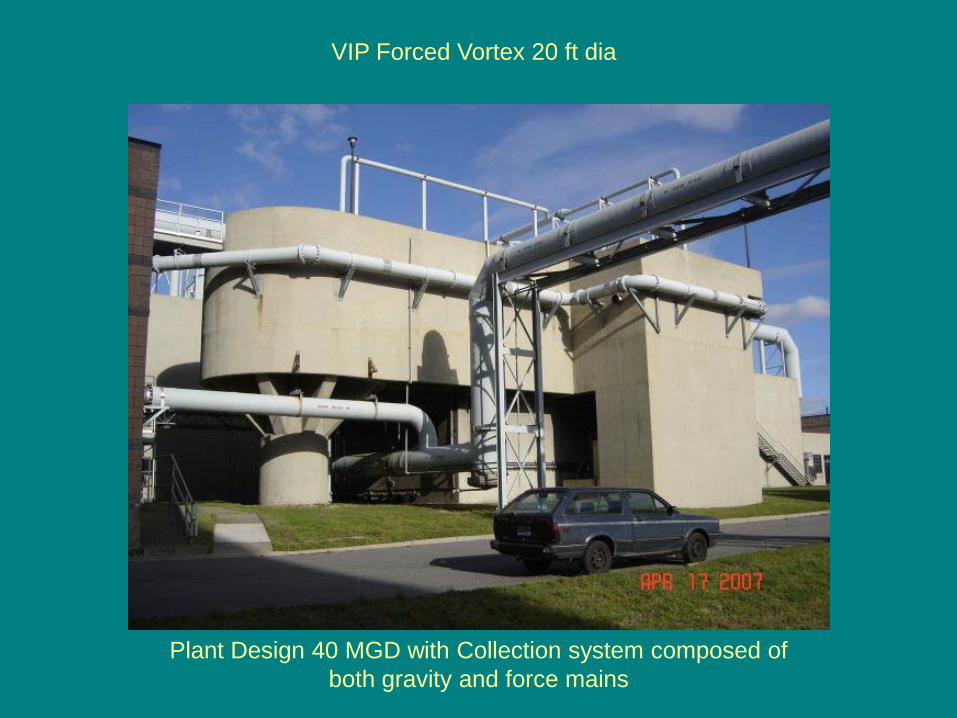
VIP Forced Vortex 20 ft dia
Plant Design 40 MGD with Collection system composed of both gravity and force mains
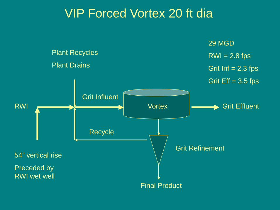
Vortex Grit Effluent
Grit Refinement
Final Product
RWI
Plant Recycles
Plant Drains
Grit Influent
Recycle
VIP Forced Vortex 20 ft dia
54” vertical rise
Preceded by RWI wet well
29 MGD
RWI = 2.8 fps
Grit Inf = 2.3 fps
Grit Eff = 3.5 fps
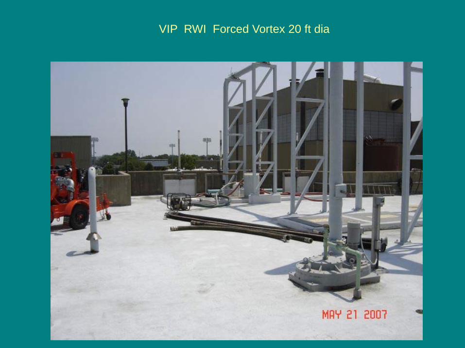
VIP RWI Forced Vortex 20 ft dia

Grit Influent and
Grit Effluent
VIP Forced Vortex 20 ft dia
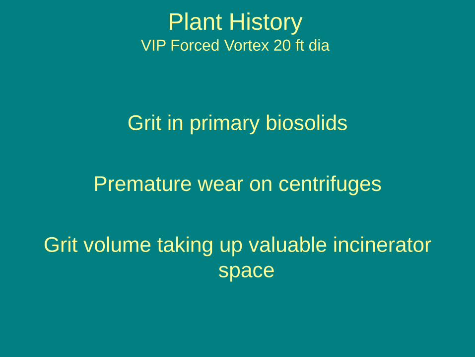
Grit in primary biosolids
Premature wear on centrifuges
Grit volume taking up valuable incinerator space
Plant HistoryVIP Forced Vortex 20 ft dia
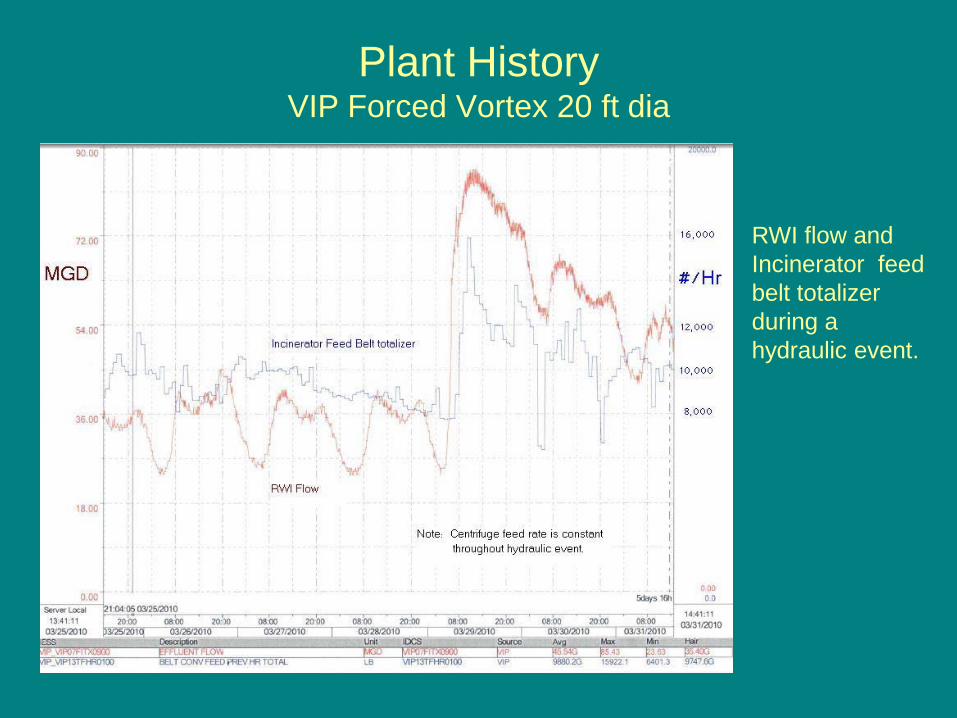
Plant HistoryVIP Forced Vortex 20 ft dia
RWI flow and Incinerator feed belt totalizer during a hydraulic event.
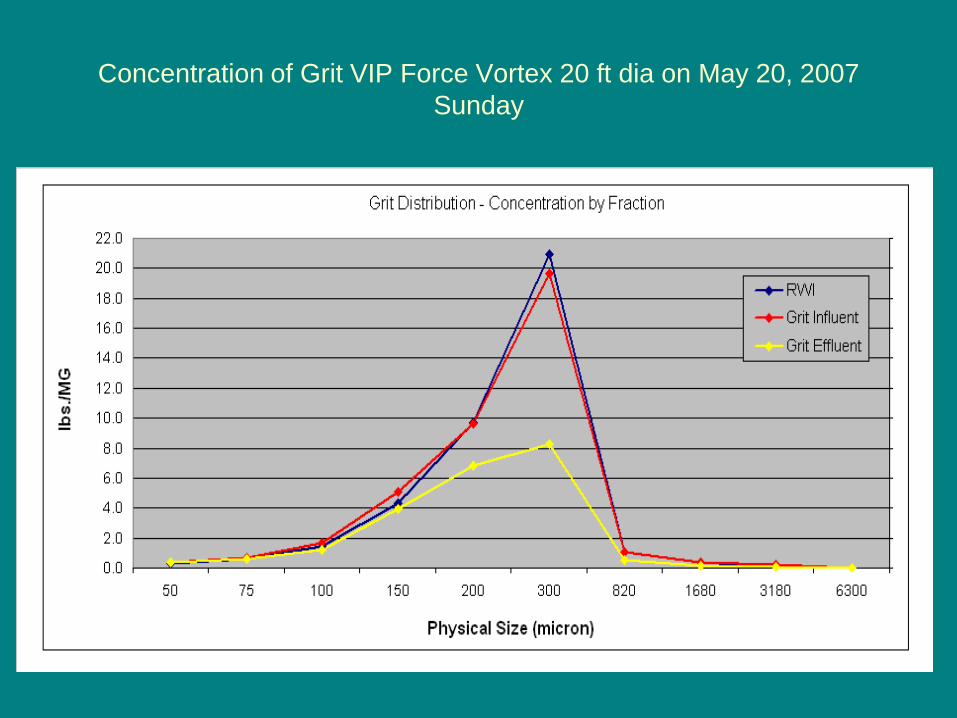
Concentration of Grit VIP Force Vortex 20 ft dia on May 20, 2007Sunday
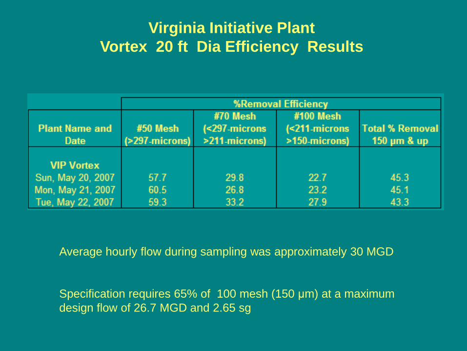
Average hourly flow during sampling was approximately 30 MGD
Specification requires 65% of 100 mesh (150 μm) at a maximum design flow of 26.7 MGD and 2.65 sg
Virginia Initiative PlantVortex 20 ft Dia Efficiency Results
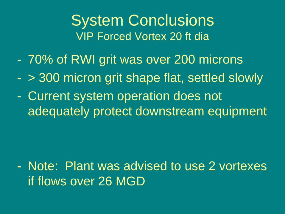
System ConclusionsVIP Forced Vortex 20 ft dia
- 70% of RWI grit was over 200 microns- > 300 micron grit shape flat, settled slowly- Current system operation does not
adequately protect downstream equipment
- Note: Plant was advised to use 2 vortexes if flows over 26 MGD
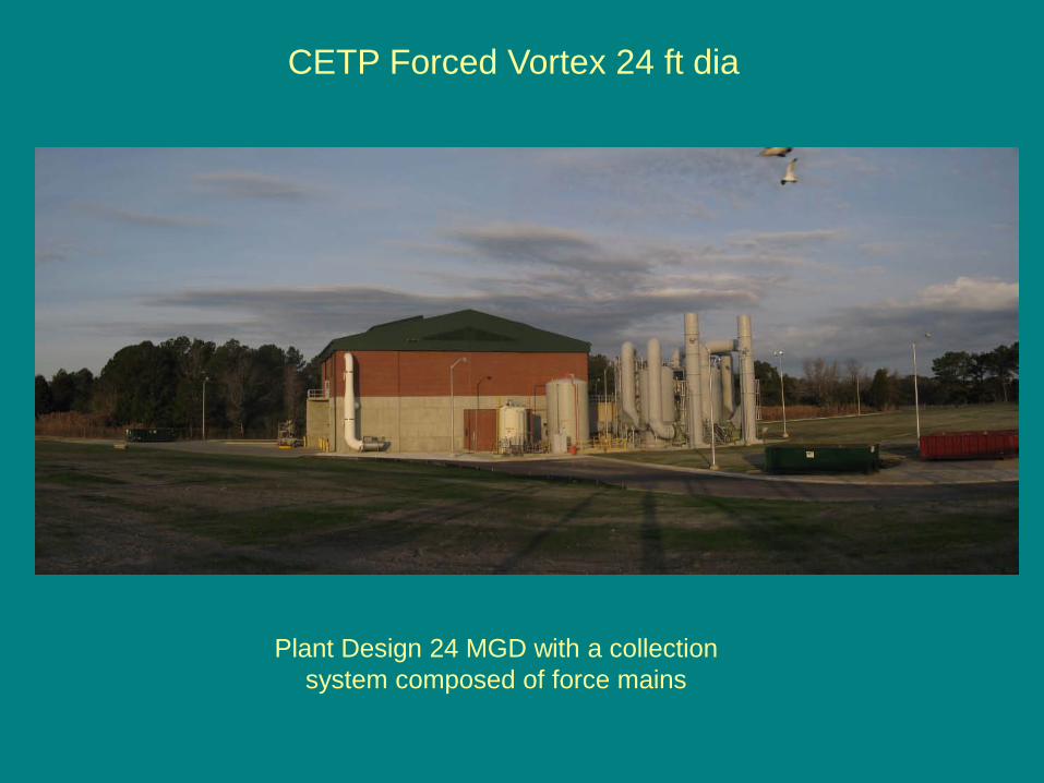
CETP Forced Vortex 24 ft dia
Plant Design 24 MGD with a collection system composed of force mains
Vortex Grit Effluent
Grit Refinement
Final Product
RWI
Plant Recycles
Plant Drains
Grit Influent
Recycle
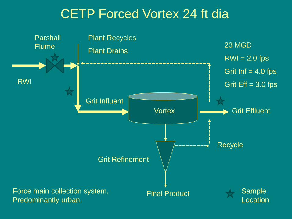
CETP Forced Vortex 24 ft dia
Force main collection system. Predominantly urban.
23 MGD
RWI = 2.0 fps
Grit Inf = 4.0 fps
Grit Eff = 3.0 fps
Parshall Flume
Sample Location
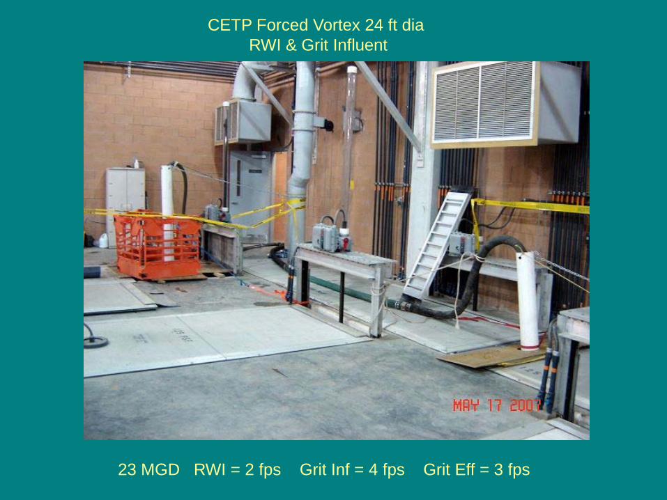
CETP Forced Vortex 24 ft dia RWI & Grit Influent
23 MGD RWI = 2 fps Grit Inf = 4 fps Grit Eff = 3 fps
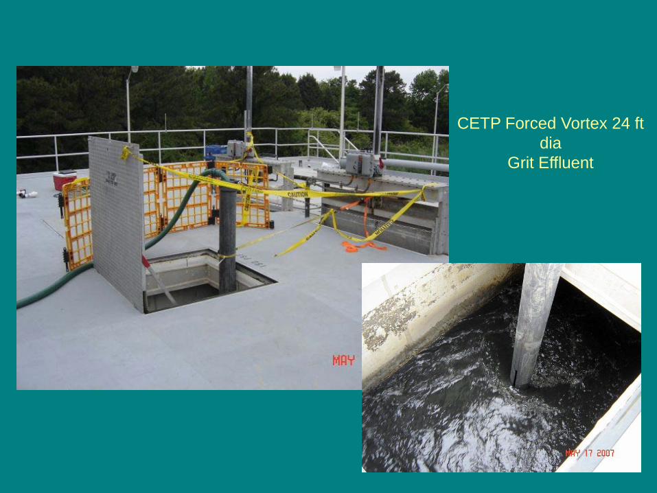
CETP Forced Vortex 24 ft dia
Grit Effluent
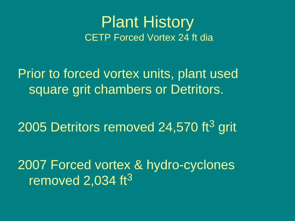
Plant HistoryCETP Forced Vortex 24 ft dia
Prior to forced vortex units, plant used square grit chambers or Detritors.
2005 Detritors removed 24,570 ft3 grit
2007 Forced vortex & hydro-cyclones removed 2,034 ft3
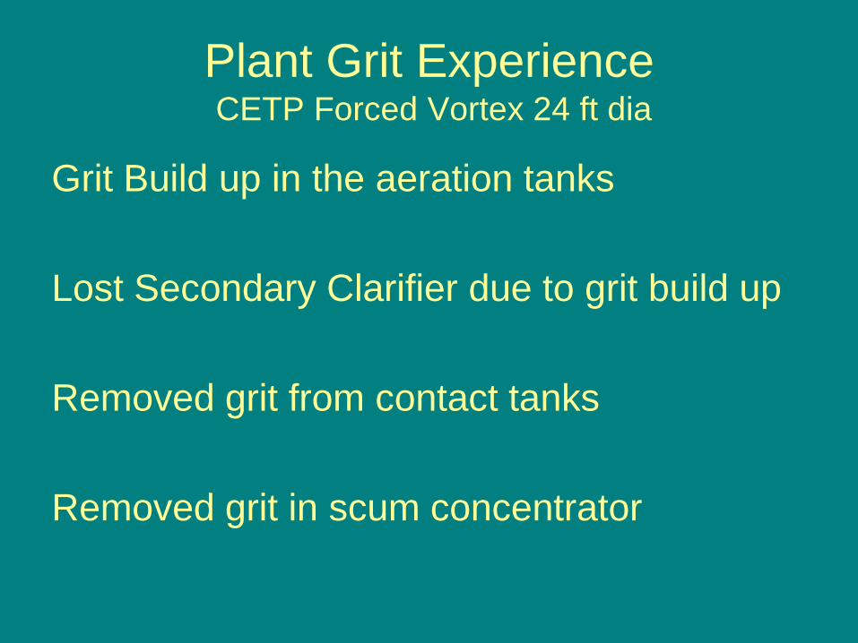
Plant Grit ExperienceCETP Forced Vortex 24 ft dia
Grit Build up in the aeration tanks
Lost Secondary Clarifier due to grit build up
Removed grit from contact tanks
Removed grit in scum concentrator
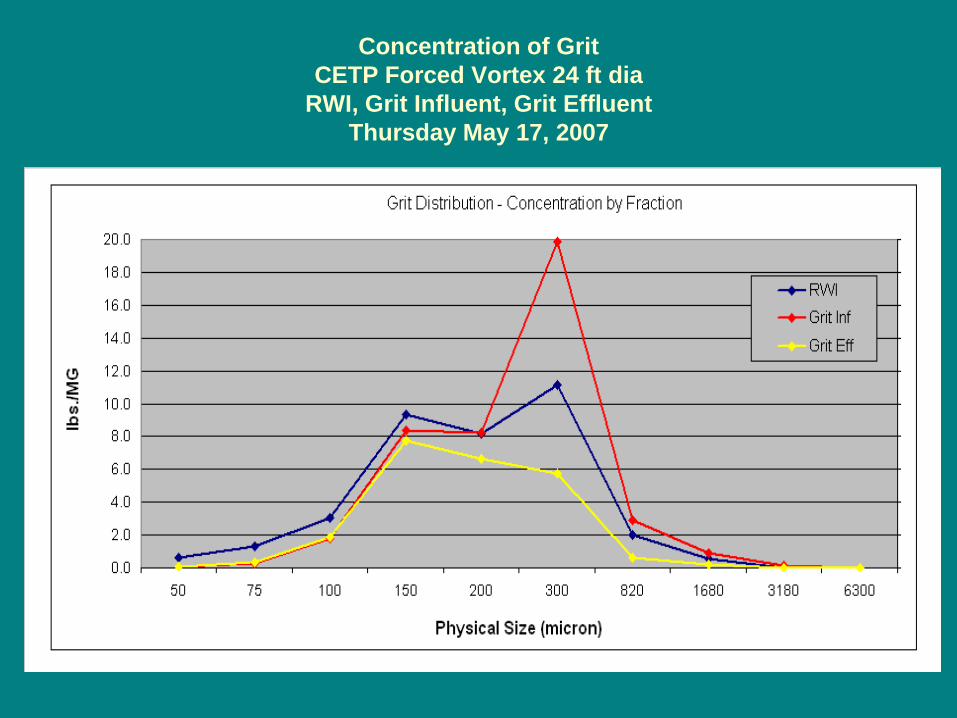
Concentration of Grit CETP Forced Vortex 24 ft dia
RWI, Grit Influent, Grit EffluentThursday May 17, 2007
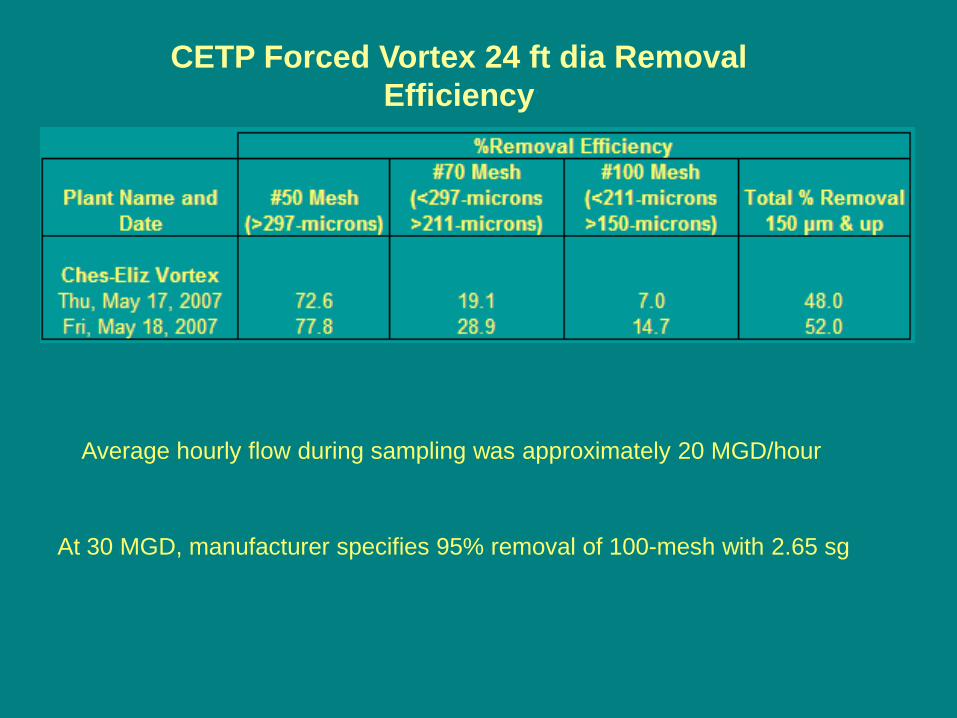
CETP Forced Vortex 24 ft dia Removal Efficiency
At 30 MGD, manufacturer specifies 95% removal of 100-mesh with 2.65 sg
Average hourly flow during sampling was approximately 20 MGD/hour
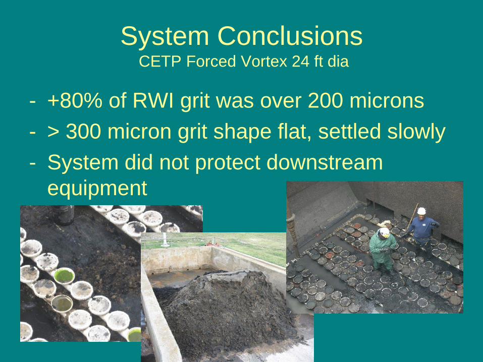
System ConclusionsCETP Forced Vortex 24 ft dia
- +80% of RWI grit was over 200 microns- > 300 micron grit shape flat, settled slowly- System did not protect downstream
equipment
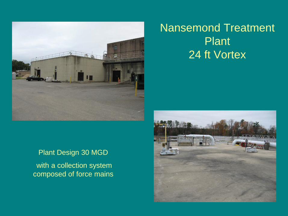
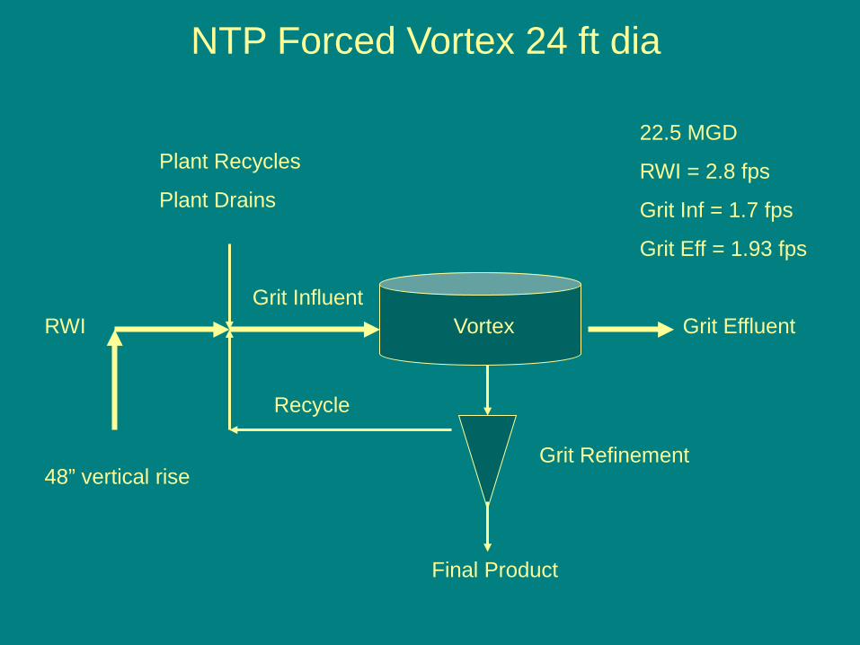
Nansemond Treatment Plant
24 ft Vortex
Plant Design 30 MGD
with a collection system composed of force mains
Vortex Grit Effluent
Grit Refinement
Final Product
RWI
Plant Recycles
Plant Drains
Grit Influent
Recycle
NTP Forced Vortex 24 ft dia
48” vertical rise
22.5 MGD
RWI = 2.8 fps
Grit Inf = 1.7 fps
Grit Eff = 1.93 fps
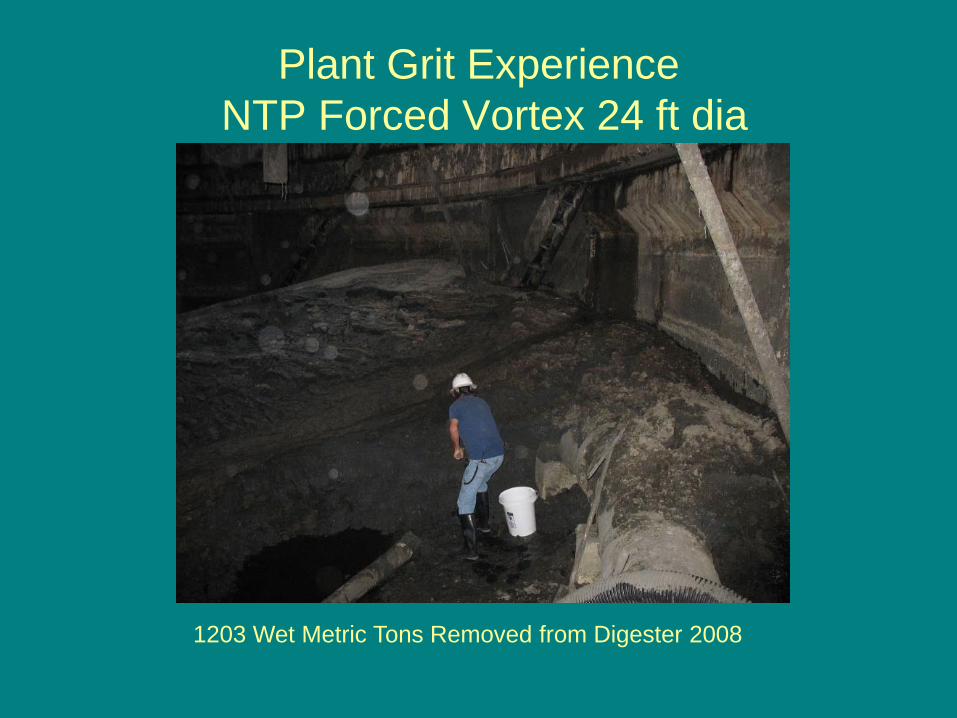
Plant Grit ExperienceNTP Forced Vortex 24 ft dia
1203 Wet Metric Tons Removed from Digester 2008
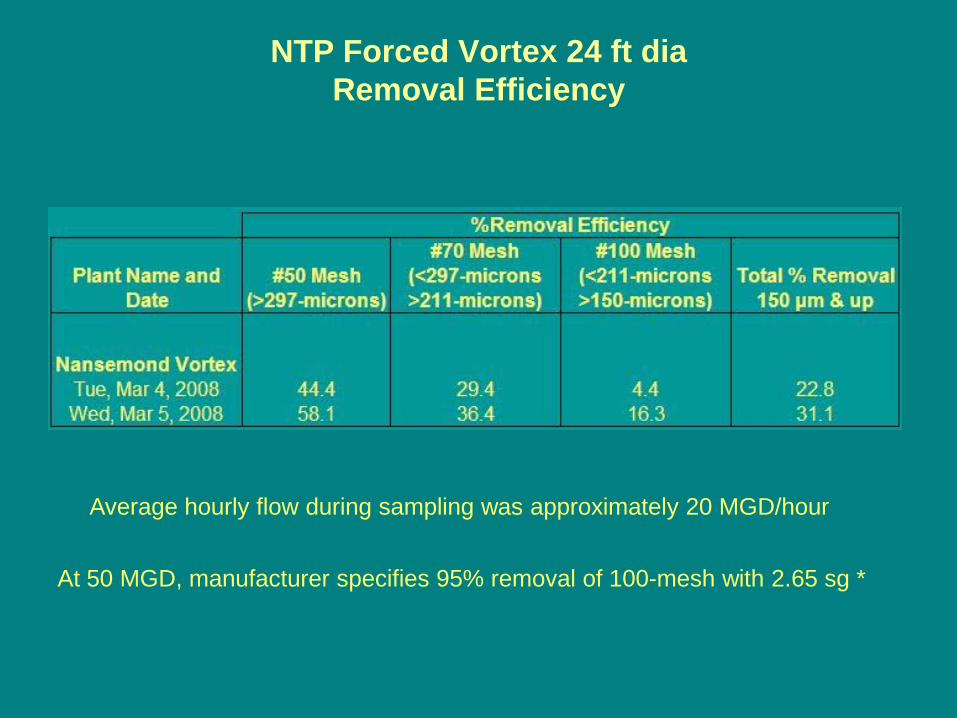
NTP Forced Vortex 24 ft dia Removal Efficiency
Average hourly flow during sampling was approximately 20 MGD/hour
At 50 MGD, manufacturer specifies 95% removal of 100-mesh with 2.65 sg *
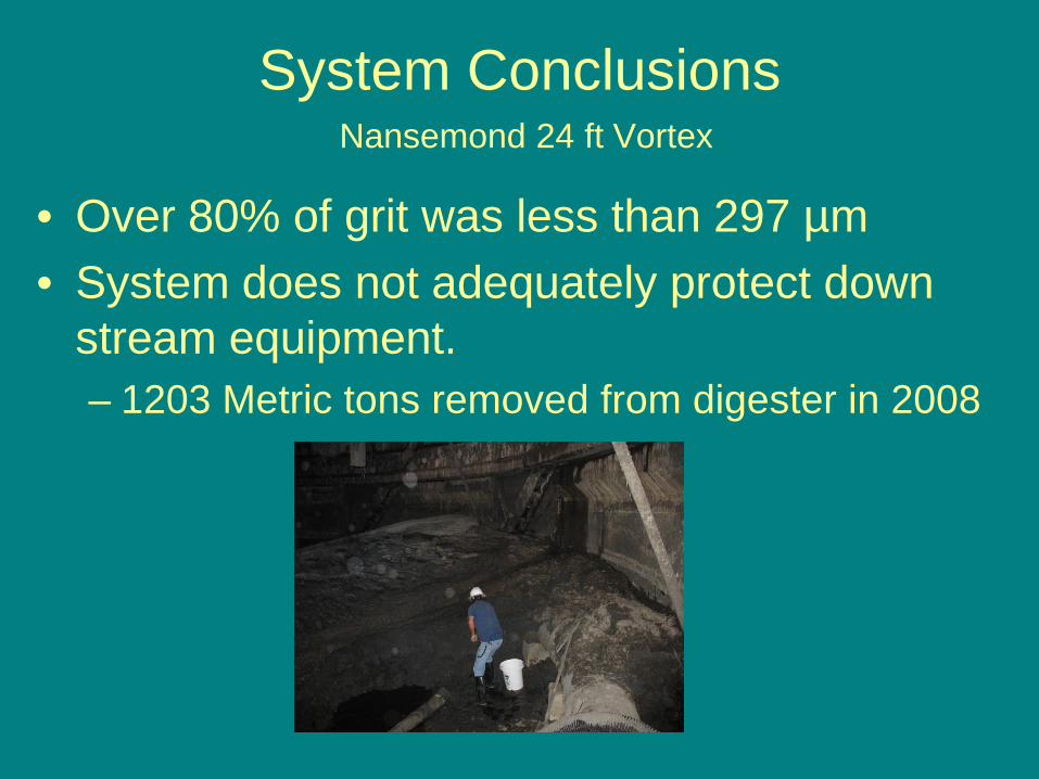
System ConclusionsNansemond 24 ft Vortex
• Over 80% of grit was less than 297 µm• System does not adequately protect down
stream equipment.– 1203 Metric tons removed from digester in 2008
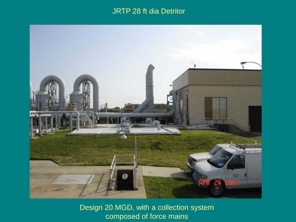
JRTP 28 ft dia Detritor
Design 20 MGD, with a collection system composed of force mains
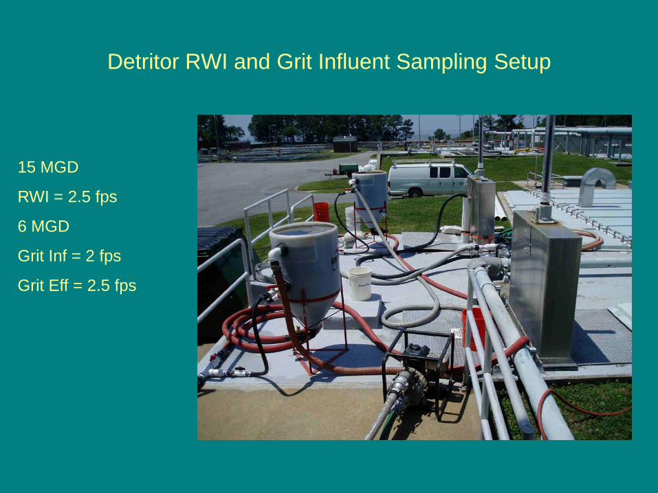
Detritor RWI and Grit Influent Sampling Setup
15 MGD
RWI = 2.5 fps
6 MGD
Grit Inf = 2 fps
Grit Eff = 2.5 fps
Plant Grit ExperienceDetritor
No down stream grit accumulations
Digesters have not accumulated appreciable amounts of grit
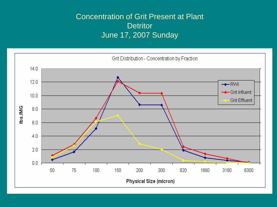
Concentration of Grit Present at Plant Detritor
June 17, 2007 Sunday
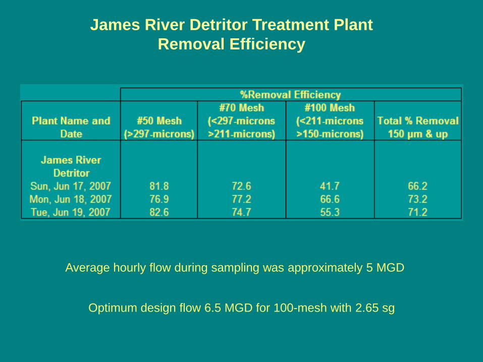
Average hourly flow during sampling was approximately 5 MGD
James River Detritor Treatment Plant Removal Efficiency
Optimum design flow 6.5 MGD for 100-mesh with 2.65 sg
System ConclusionsDetritor
- >40% of RWI grit was over 200 microns. Data suggest large grit deposits in collection system.
- System operated within design flows- Plant operated with 3 detritors, providing
adequate protection of downstream equipment
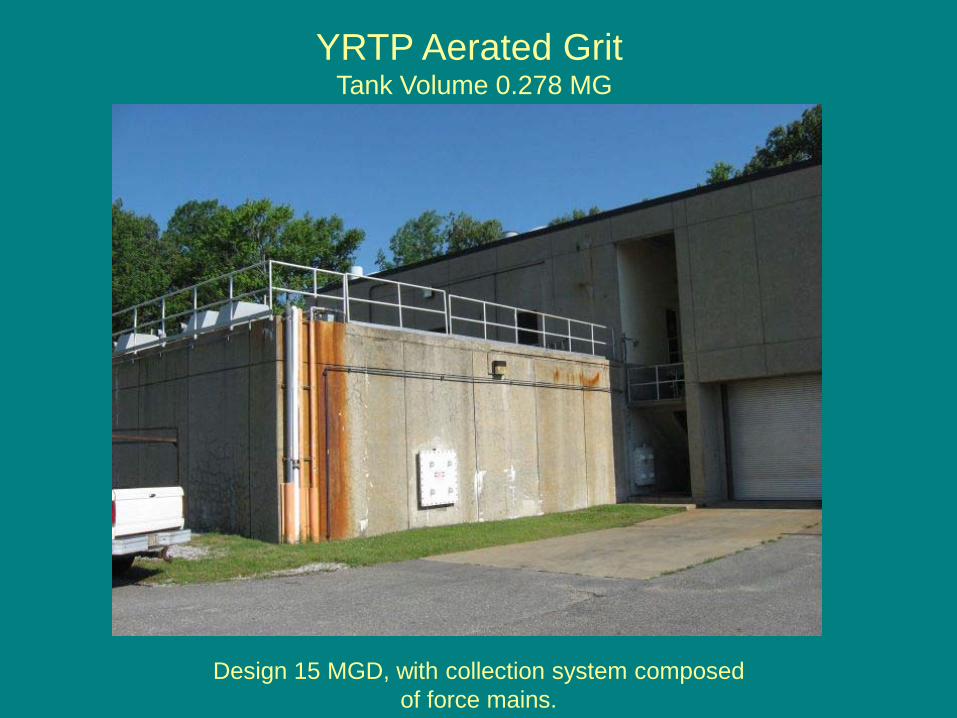
YRTP Aerated Grit Tank Volume 0.278 MG
Design 15 MGD, with collection system composed of force mains.
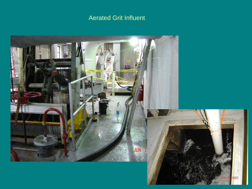
Aerated Grit Influent
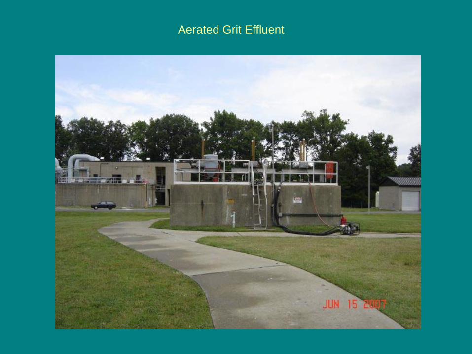
Aerated Grit Effluent
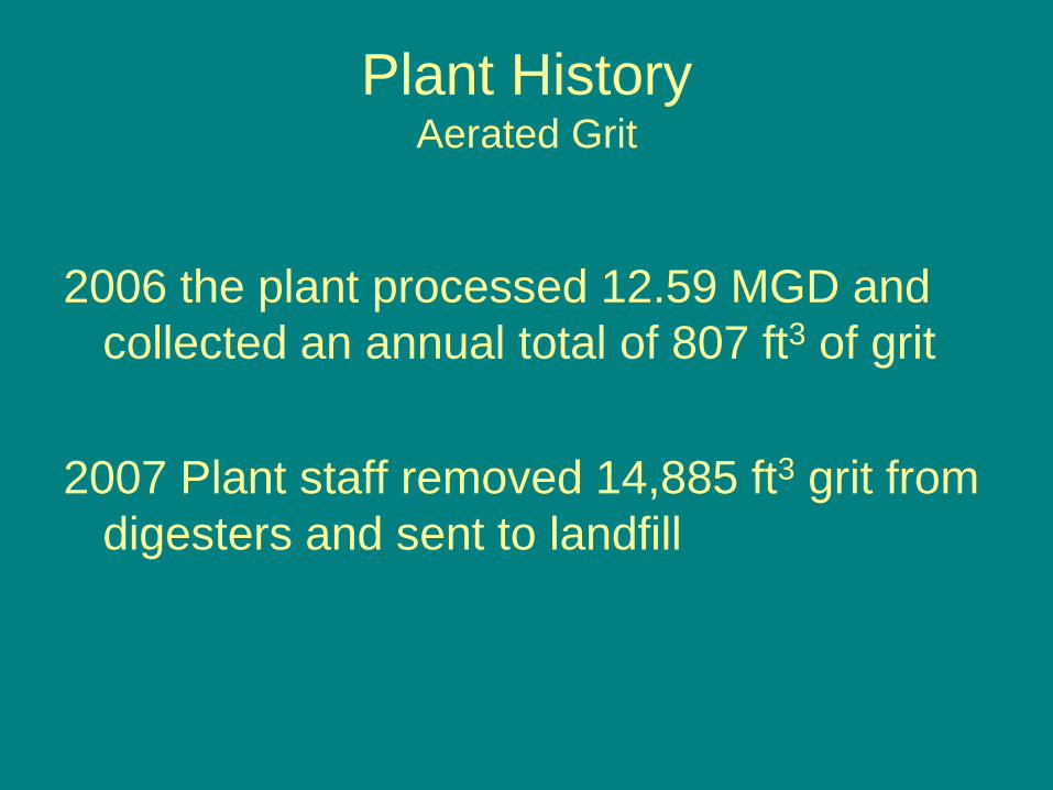
Plant HistoryAerated Grit
2006 the plant processed 12.59 MGD and collected an annual total of 807 ft3 of grit
2007 Plant staff removed 14,885 ft3 grit from digesters and sent to landfill
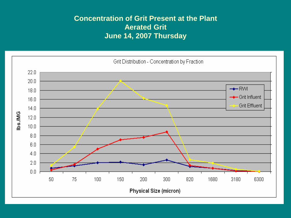
Concentration of Grit Present at the Plant Aerated Grit
June 14, 2007 Thursday
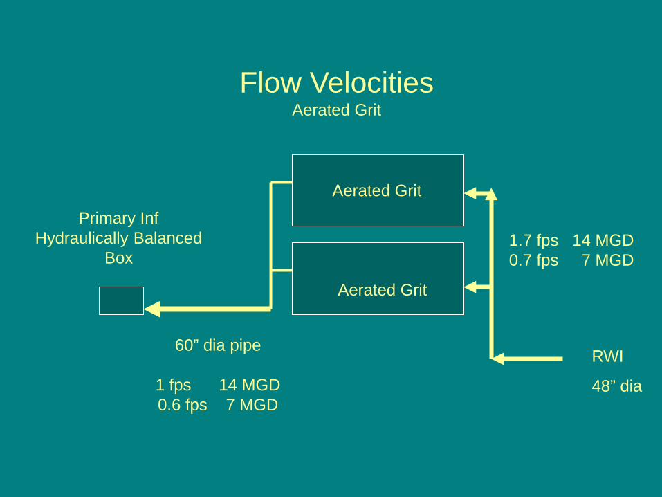
Aerated Grit
RWI
48” dia
60” dia pipe
1 fps 14 MGD0.6 fps 7 MGD
Primary Inf Hydraulically Balanced
Box
Flow VelocitiesAerated Grit
1.7 fps 14 MGD0.7 fps 7 MGD
Aerated Grit
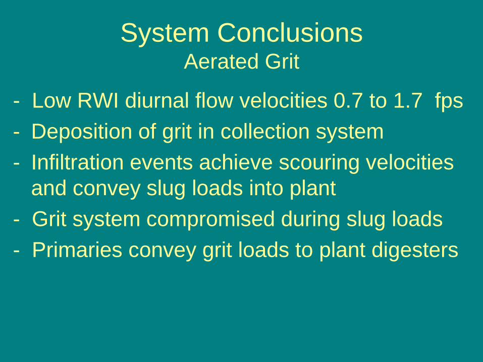
System ConclusionsAerated Grit
- Low RWI diurnal flow velocities 0.7 to 1.7 fps- Deposition of grit in collection system- Infiltration events achieve scouring velocities
and convey slug loads into plant- Grit system compromised during slug loads- Primaries convey grit loads to plant digesters
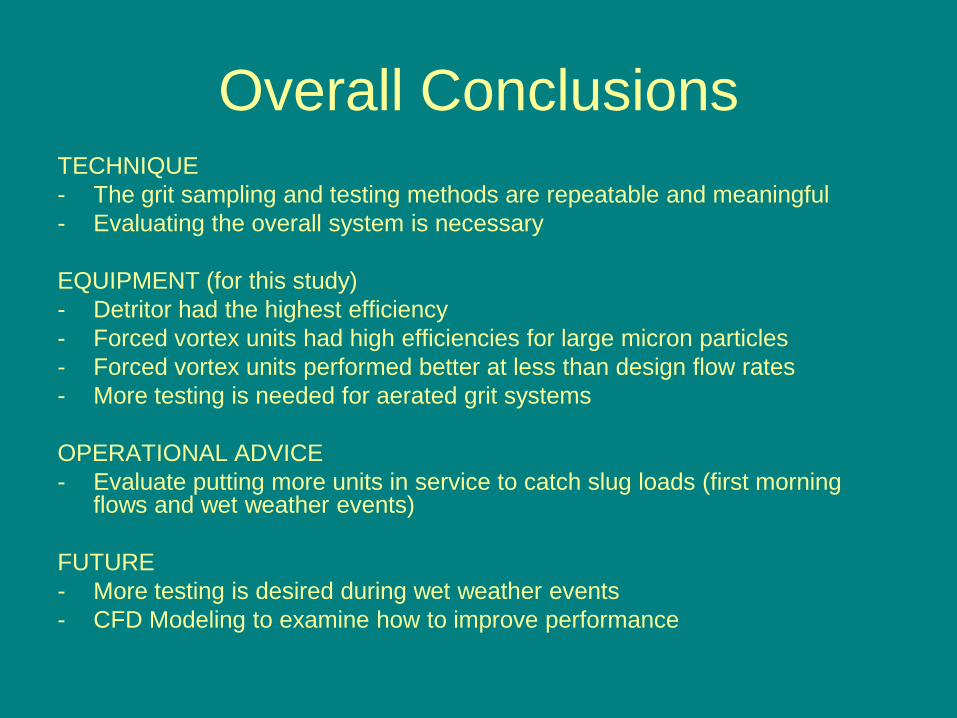
Overall ConclusionsTECHNIQUE- The grit sampling and testing methods are repeatable and meaningful- Evaluating the overall system is necessary
EQUIPMENT (for this study)- Detritor had the highest efficiency- Forced vortex units had high efficiencies for large micron particles- Forced vortex units performed better at less than design flow rates- More testing is needed for aerated grit systems
OPERATIONAL ADVICE- Evaluate putting more units in service to catch slug loads (first morning
flows and wet weather events)
FUTURE- More testing is desired during wet weather events- CFD Modeling to examine how to improve performance
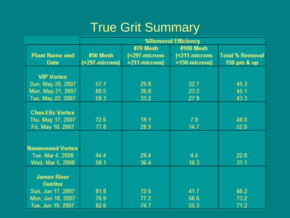
True Grit Summary

Special Thanks to my Editor
Mardane McLemore
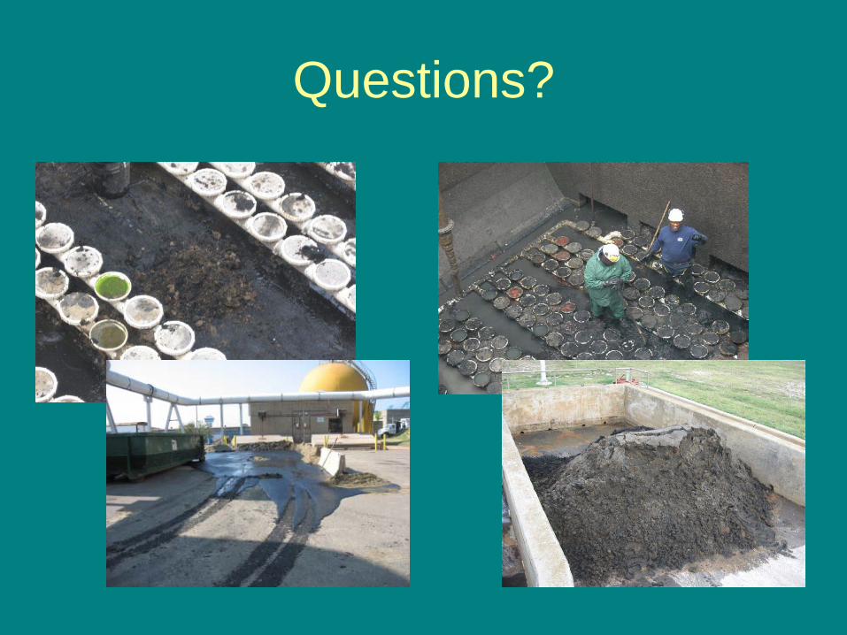
Questions?