gridcooler installation manual 175 lr final3
DESCRIPTION
ingenieria navalTRANSCRIPT

R.W. Fernstrum & Company
Installation andMaintenance ManualForm 175
GRIDCOOLER®
KEEL COOLER

Maintenance Manual 7/10/12 10:11 AM Page 2
installation and maintenance manual form 170 index
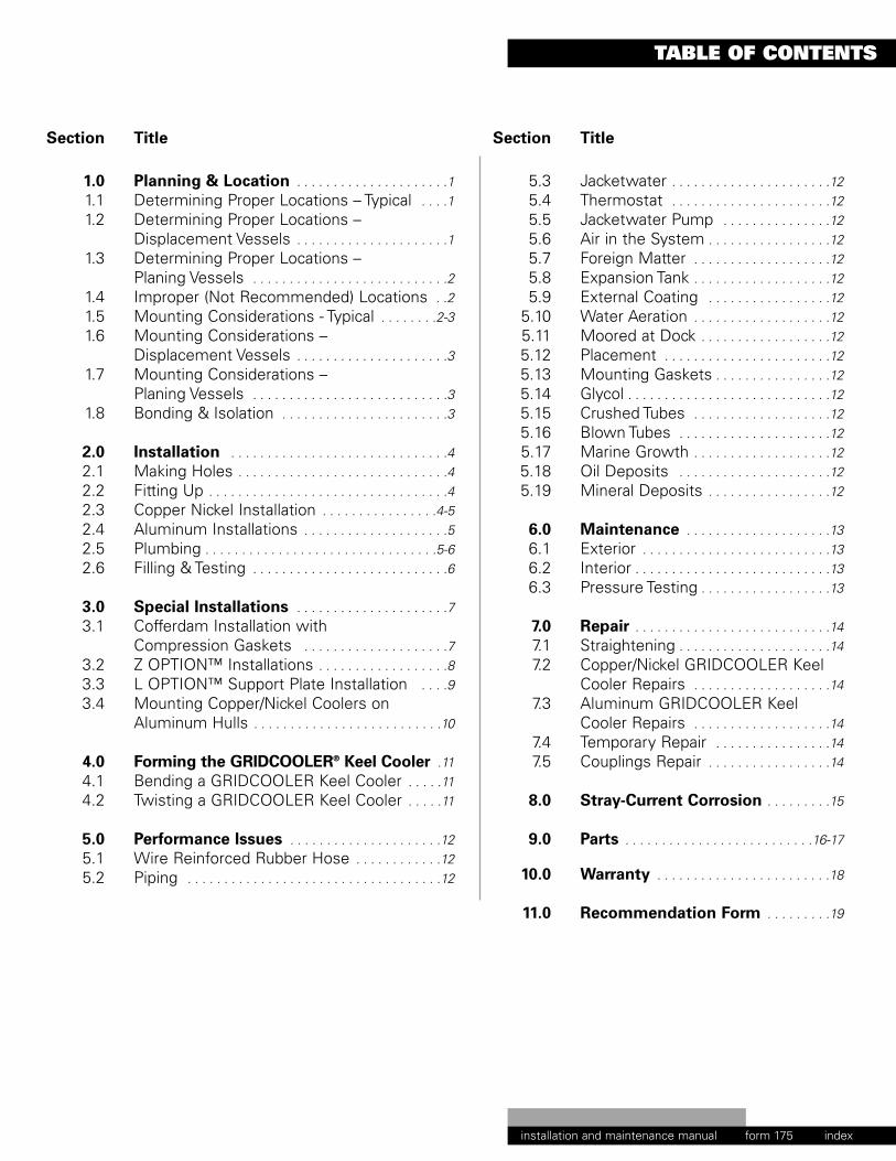
TABLE OF CONTENTS
Section Title
1.0 Planning & Location . . . . . . . . . . . . . . . . . . . . .11.1 Determining Proper Locations – Typical . . . .11.2 Determining Proper Locations –
Displacement Vessels . . . . . . . . . . . . . . . . . . . . .11.3 Determining Proper Locations –
Planing Vessels . . . . . . . . . . . . . . . . . . . . . . . . . . .21.4 Improper (Not Recommended) Locations . .21.5 Mounting Considerations - Typical . . . . . . . .2-31.6 Mounting Considerations –
Displacement Vessels . . . . . . . . . . . . . . . . . . . . .31.7 Mounting Considerations –
Planing Vessels . . . . . . . . . . . . . . . . . . . . . . . . . . .31.8 Bonding & Isolation . . . . . . . . . . . . . . . . . . . . . . .3
2.0 Installation . . . . . . . . . . . . . . . . . . . . . . . . . . . . . .42.1 Making Holes . . . . . . . . . . . . . . . . . . . . . . . . . . . . .42.2 Fitting Up . . . . . . . . . . . . . . . . . . . . . . . . . . . . . . . . .42.3 Copper Nickel Installation . . . . . . . . . . . . . . . .4-52.4 Aluminum Installations . . . . . . . . . . . . . . . . . . . .52.5 Plumbing . . . . . . . . . . . . . . . . . . . . . . . . . . . . . . . .5-62.6 Filling & Testing . . . . . . . . . . . . . . . . . . . . . . . . . . .6
3.0 Special Installations . . . . . . . . . . . . . . . . . . . . .73.1 Cofferdam Installation with
Compression Gaskets . . . . . . . . . . . . . . . . . . . .73.2 Z OPTION™ Installations . . . . . . . . . . . . . . . . . .83.3 L OPTION™ Support Plate Installation . . . .93.4 Mounting Copper/Nickel Coolers on
Aluminum Hulls . . . . . . . . . . . . . . . . . . . . . . . . . .10
4.0 Forming the GRIDCOOLER® Keel Cooler .114.1 Bending a GRIDCOOLER Keel Cooler . . . . .114.2 Twisting a GRIDCOOLER Keel Cooler . . . . .11
5.0 Performance Issues . . . . . . . . . . . . . . . . . . . . .125.1 Wire Reinforced Rubber Hose . . . . . . . . . . . .125.2 Piping . . . . . . . . . . . . . . . . . . . . . . . . . . . . . . . . . . .12
Section Title
5.3 Jacketwater . . . . . . . . . . . . . . . . . . . . . .125.4 Thermostat . . . . . . . . . . . . . . . . . . . . . .125.5 Jacketwater Pump . . . . . . . . . . . . . . .125.6 Air in the System . . . . . . . . . . . . . . . . .125.7 Foreign Matter . . . . . . . . . . . . . . . . . . .125.8 Expansion Tank . . . . . . . . . . . . . . . . . . .125.9 External Coating . . . . . . . . . . . . . . . . .12
5.10 Water Aeration . . . . . . . . . . . . . . . . . . .125.11 Moored at Dock . . . . . . . . . . . . . . . . . .125.12 Placement . . . . . . . . . . . . . . . . . . . . . . .125.13 Mounting Gaskets . . . . . . . . . . . . . . . .125.14 Glycol . . . . . . . . . . . . . . . . . . . . . . . . . . . .125.15 Crushed Tubes . . . . . . . . . . . . . . . . . . .125.16 Blown Tubes . . . . . . . . . . . . . . . . . . . . .125.17 Marine Growth . . . . . . . . . . . . . . . . . . .125.18 Oil Deposits . . . . . . . . . . . . . . . . . . . . .125.19 Mineral Deposits . . . . . . . . . . . . . . . . .12
6.0 Maintenance . . . . . . . . . . . . . . . . . . . .136.1 Exterior . . . . . . . . . . . . . . . . . . . . . . . . . .136.2 Interior . . . . . . . . . . . . . . . . . . . . . . . . . . .136.3 Pressure Testing . . . . . . . . . . . . . . . . . .13
7.0 Repair . . . . . . . . . . . . . . . . . . . . . . . . . . .147.1 Straightening . . . . . . . . . . . . . . . . . . . . .147.2 Copper/Nickel GRIDCOOLER Keel
Cooler Repairs . . . . . . . . . . . . . . . . . . .147.3 Aluminum GRIDCOOLER Keel
Cooler Repairs . . . . . . . . . . . . . . . . . . .147.4 Temporary Repair . . . . . . . . . . . . . . . .147.5 Couplings Repair . . . . . . . . . . . . . . . . .14
8.0 Stray-Current Corrosion . . . . . . . . .15
9.0 Parts . . . . . . . . . . . . . . . . . . . . . . . . . .16-17
10.0 Warranty . . . . . . . . . . . . . . . . . . . . . . . .18
11.0 Recommendation Form . . . . . . . . .19
Maintenance Manual 7/10/12 10:11 AM Page 3
form 175

Maintenance Manual 7/10/12 10:11 AM Page 4

section 1 PLANNING & LOCATIONinstallation and maintenance manual form 170 page 1
PLANNING & LOCATION
1.0 PLANNING & LOCATION
To function properly, the FERNSTRUM® GRIDCOOLER® KeelCooler must be properly located on your vessel’s hull. Pleaseconsider the following before installing your keel cooler onmost types of vessels. For additional details on displacementor planning hulls, refer to the appropriate sections:
1.1 DETERMINING PROPER LOCATION –TYPICAL
1.1.1 Sea water must flow over the entire length of the unit.1.1.2 Always install the unit parallel, not transverse,
to the skeg or keel. See Figures 1 & 2.
FIG. 1 External type installation with E1 OPTIONend-mounted zinc anodes using fairing blocksfor protection and streamlining.
FIG. 2 Recess type installation with E1 OPTIONend-mounted zinc anodes for reduced drag inhigh-speed craft.
1.1.3 When using a two-circuit cooling system, consisting of ahigh temperature jacketwater circuit and a low temperatureaftercooler circuit, make certain the aftercooler circuitcooler is placed forward of the jacketwater circuit cooler.When room allows, they can be installed side by side withthe aftercooler circuit lower on the hull (i.e. closer to theskeg or keel) and a divider plate between the high and lowtemperature units.
1.1.4 When the GRIDCOOLER unit is used on a generator set orif your application requires sizing for a hull speed of 0knots, make sure that sea water can freely circulate pastthe cooler tubes. Do not recess a generator set unit on thebottom of a flat bottom boat unless the hull section wherethe unit will be mounted inclines a minimum of 20 degrees(from forward to aft) to avoid entrapping raw hot wateraround the tubes. See Figure 3.
1.2 DETERMINING PROPER LOCATION –DISPLACEMENT VESSELS
1.2.1 On vessels performing pushing, towing, dragging or pullingoperations, install the unit as near to the propelleras possible (but not directly above it) to take advantageof its slip-stream during extreme towing operations.See Figure 3.
FIG. 3 Recessed installation is made by welding ina box-shaped recess in the underside of the hull.Note aft end of recess is tapered to prevent hotwater entrapment.
1.2.2 When installing a unit on the side of a hull, position it wellbelow the water line to avoid aerated surface water. Takethe bow wave into consideration. Aeration reduces heattransfer and can cause overheating. See Figure 4.
Maintenance Manual 7/10/12 10:11 AM Page 5
form 175

FIG. 6 Example of external guarding
section 1 PLANNING & LOCATIONinstallation and maintenance manual form 170 page 2
PLANNING & LOCATION
FIG. 4 Side mounted coolers well below water line.
1.3 DETERMINING PROPER LOCATION –PLANING VESSELS
1.3.1 For planing hull vessels, locate the unit as far aft aspossible to avoid aeration.
1.4 IMPROPER (NOT RECOMMENDED) LOCATIONS
1.4.1 The area of the hull where the GRIDCOOLER® Keel Cooleris installed must not vibrate or flex severely.
1.4.2 To eliminate unnecessary stress and vibration on thecooler, do not locate the unit directly below engine mountsor above the propeller(s).
1.4.3 Make sure that hot water is not discharged on or nearthe unit.
1.4.4 Do not locate the unit on the front 1/3 of the hull fordisplacement hulls. Bowthruster coolers could be anexception, depending on the vessel.
1.4.5 The GRIDCOOLER Keel Cooler is designed to be mounteddirectly to the hull. Do not mount the unit to any externalstructure without first consulting the factory.
1.5 MOUNTING CONSIDERATIONS – TYPICAL
1.5.1 Some classed vessels (ABS or Coast Guard, for example)may require cofferdams, check with your local officials formore information. For this type of installation, seeCofferdam Installation in Section 3.1.
1.5.2 The GRIDCOOLER unit can be canted from the hull(sideways) to vertically align the nozzles. This canreduce interference problems with stringers oncofferdam installations. See Figure 5.(referred to section 3.1 for cofferdam installation)
FIG. 5 Canted Installation with Cofferdam.
1.5.3 If the unit is recessed into the hull, make sure that it has a1-1/2 in. (38 mm) minimum clearance on all sides (this doesnot include between the hull and the top of the cooler). Therecess should be no deeper than 1/2 in. (13 mm) plus thehull projection (listed on installation drawing) of the cooler.
1.5.4 In extreme cases, where logs, debris, or dragging bottommay endanger the unit, a protective guard may be mountedover the unit. Make certain the grill guard does not covermore than 25% of the face opening. For examples ofprotective guards and different installations that have beenused, see Figures 6 and 7.
Maintenance Manual 7/10/12 10:11 AM Page 6
form 175

section 1 PLANNING & LOCATIONinstallation and maintenance manual form 170 page 3
PLANNING & LOCATION
FIG. 7 Side mounted coolers
1.5.5 The unit can be bent to conform to the hull. The bendingcan be done at the yard or by R. W. Fernstrum & Company.Contact us if you are considering bending a unit. SeeSection 4.0 – Forming the GRIDCOOLER® Keel Cooler.
1.6 MOUNTING CONSIDERATIONS –DISPLACEMENT VESSELS
1.6.1 Owners of vessels with displacement hulls moving at lessthan 10 knots may find an external mounting with fairingblocks to their advantage; provided there isn’t much chanceof the unit being damaged in their operating environment
1.6.2 When recessing the unit into the side of the hull forgenerator sets and/or equipment operating at dockside,angle the top of the recess box to allow convection currentover the cooler. See Figure 8.
FIG. 8 Side Mounted Recess.
NOTE: Recess box with angled top suggested forgenerator set and equipment operating at dockside only. NOT required for propulsion engines.
1.6.3 When installing a multiple-pass unit on an incline, makesure that the nozzles are at the high end to avoid airentrapment. See Figure 9.
1.6.4 If coolers must be installed with the nozzles at the low end,special units can be ordered with additional vents in thestud end of the cooler.
FIG. 9 U-Flow unit with E1 OPTION end mounted zincanodes mounted on rake of vessel.
1.6.5 If side plates and fairing blocks are used, make sure thatthe side plates are scalloped (notched) out so they will notentrap water. Fairing blocks are most effective wheninstalled with a 4 to 1 slope. See Figures 1 & 6.
1.7 MOUNTING CONSIDERATIONS –PLANING VESSELS
1.7.1 If you aren’t sure as to whether or not you should recessthe unit, we recommend using a recess on planing hullsand vessels moving at 10 or more knots.
1.7.2 High speed applications (10+ knots) can reduce the 1-1/2in. clearance in section 1.3.4 to 1/2 in. minimum due toincreased raw water flow over the cooler at high speed.
1.7.3 High speed applications and others that use E1 OPTION™coolers should take into consideration the removal andreplacement of zinc electrodes when sizing the length of arecess. See Figure 2.
1.8 BONDING OR ISOLATIONTO MINIMIZE CORROSION
1.8.1 It is recommended that the installer consult with acorrosion engineer to review the corrosion protectionsystem of the vessel to determine the best mode ofinstallation for their particular situation.Typically it is common practice to isolate the heatexchanger from the hull. This ensures that the antifoulingproperty of the copper nickel is at full potential. However,there are other variables that may effect the decisionwhether to isolate or bond the unit.
Maintenance Manual 7/10/12 10:11 AM Page 7
form 175

FIG. 10 Mounting Parts Placement
NOTE: IF CONCAVE WASHERS ARE USED,MAKE SURE CONCAVE SIDE IS DOWN ONGASKET. FOR NIPPLE WASHERS THAT ARECAST, PLACE THE ROUGH SIDE AGAINSTTHE GASKET.
section 2 INSTALLATIONinstallation and maintenance manual form 170 page 4
INSTALLATION
2.0 INSTALLATION
Once you have decided on he correct location, use thefollowing steps as a guideline for installing yourGRIDCOOLER® Keel Cooler:
2.1 MAKING HOLES
2.1.1 Measure the distance between the Inlet & Outlet nozzlesfrom center to center (also measure to the centers of thesupport studs when applicable) before cutting holes forthem in the ship’s hull.
2.1.2 Make the holes through the hull 1/4 in. (6.4 mm) diameteroversized.
2.1.3 Make sure that the hull surfaces where the unit will bemounted are smooth and properly aligned (on steel hulls, ifyou burn the holes, grind the edges smooth afterwards).This will allow the gaskets to seal properly and insure thatno undue stress will be placed on the cooler.
2.2 FITTING UP
2.2.1 Under normal conditions, the compression of the mountinggaskets puts sufficient tension on the nozzle nuts (andsupport bolt nuts when applicable) to prevent them fromworking loose. To seal out water, apply a polysulfide rubbersealant like BoatLIFE Caulk or 3M Marine Sealant 101around the gaskets, washers, and the points where thenozzles and support bolts penetrate the hull beforeassembly. Remember to tighten the nuts a second time,after the caulking has set.
NOTE: BoatLIFE is available from Life Industries(www.boatlife.com), call 800-382-9706 for adealer near you. Marine Sealant 101 is availablefrom 3M (www.3m.com), call 888-364-3577 for adealer near you.
2.3 COPPER/NICKEL INSTALLATION
2.3.1 Mounting gaskets supplied with the GRIDCOOLER KeelCooler must be used to provide proper spacing betweenthe unit and the ship’s hull. See Figure 10.
NOTE: EXTERIOR GASKETS: All “BN” & “CN” SeriesModels have 1/2 in. (12.7 mm) gaskets asstandard. All legacy “B” & “C” Series Modelshave 1/4 in. (6.4 mm) gaskets standard. The“D” Series Models have 3/4 in. (19 mm) gasketsstandard, however, 1/4 in. gaskets are availableupon request.
NOZZLE NUT
NOZZLE (MACHINED) WASHER(FINISHED FACE TOWARD NUT)
HOSE CONNECTOR
NOZZLE
HULL
BEAD OF SEALANT
DRAIN PLUG
NOZZLE GASKET
BEAD OF SEALANT
INSULATOR(CUSTOMER PROVIDED PVC PIPE
CUT TO HULL THICKNESS)
HEADER GASKET
ZINC ELECTRODE
Maintenance Manual 7/10/12 10:11 AM Page 8
form 175
COPPER/NICKEL UNITNUT TORQUES FT.-LBS. (KG-M)
NOZZLE THREAD SIZE
HEADER STUD SUPPORT BOLT
.75”19mm
50 - 60(7 - 8)
.625 - .75”16 - 19mm
35 - 40(5 - 5.5)
.5 - .75”13 - 19mm
20 - 25(3 - 3.5)
1”25.4mm
50 - 60(7 - 8)
1 - 1.5”25 - 38mm
75 - 100(10 - 14)
2”51mm
125 - 150(17 - 21)
2.5 - 3.5”63 - 89mm
200 - 250(28 - 35)
section 2 INSTALLATIONinstallation and maintenance manual form 170 page 5
INSTALLATION
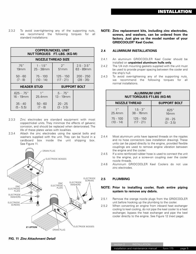
2.3.2 To avoid over-tightening any of the supporting nuts,we recommend the following torques for allstandard installations:
2.3.3 Zinc electrodes are standard equipment with mostcopper/nickel units. They minimize the effects of galvaniccorrosion, and should be replaced when deteriorated. Thelife of these plates varies with localities.
2.3.4 Attach the zinc electrodes using the special bolts andwashers supplied with the unit. They can be found in acardboard box inside the unit shipping box.See Figure 11.
FIG. 11 Zinc Attachment Detail
NOTE: Zinc replacement kits, including zinc electrodes,screws, and washers, can be ordered from thefactory. Just give us the model number of yourGRIDCOOLER® Keel Cooler.
2.4 ALUMINUM INSTALLATIONS
2.4.1 An aluminum GRIDCOOLER Keel Cooler should beinstalled on unpainted aluminum hulls only.
2.4.2 The 1/4 inch mounting gaskets supplied with the unit mustbe used to provide proper spacing between the cooler andthe ship’s hull.
2.4.3 To avoid over-tightening any of the supporting nuts,we recommend the following torques for allnormal installations.
2.4.4 Most aluminum units have tapered threads on the nipplesand no hose connectors (see installation drawing). Theseunits can be piped directly to the engine, provided flexiblecouplings are used to remove engine vibration betweenthe engine and the cooler.
2.4.5 If a wire reinforced rubber hose is used to connect the unitto the engine, put a screw-on coupling over the coolernozzle threads.
2.4.6 Aluminum GRIDCOOLER Keel Coolers do not usezinc electrodes.
2.5 PLUMBING
NOTE: Prior to installing cooler, flush entire pipingsystem to remove any debris.
2.5.1 Remove the orange nozzle plugs from the GRIDCOOLERunit before hooking up the plumbing to the cooler.
2.5.2 When converting an engine from inboard heat exchangercooling to keel cooling, do not pipe the keel cooler to a heatexchanger, bypass the heat exchanger and pipe the keelcooler directly to the engine. See Figure 12 (next page).
ALUMINUM UNITNUT TORQUES FT-LBS (KG-M)
NOZZLE THREAD SUPPORT BOLT
1”25.4mm
75 - 100(10 - 14)
1.5 - 3”38 - 76mm
125 - 150(17 - 21)
.625”16mm
20 - 25(3 - 3.5)
DRAIN PLUG
ELECTRODE BOSSES
ZINCELECTRODE
PLATE
ELECTRODEWASHERS
ELECTRODESCREWS
ZINCELECTRODE
PLATE
ELECTRODEWASHERS
ELECTRODESCREWS
ELECTRODE BOSSES
DRAIN PLUGE1 OPTION
Maintenance Manual 7/10/12 10:11 AM Page 9
form 175

section 2 INSTALLATIONinstallation and maintenance manual form 170 page 6
INSTALLATION
FIG. 12 Plumb keel cooler directly to the engine(simplified)
2.5.3 As a rule-of-thumb, the expansion tank for your coolingsystem should be able to hold approximately 10% of thetotal cooling system coolant. Contact your engine dealerfor the exact size.
2.5.4 When piping, do not use tubing or fittings smaller than theengine or keel cooler connections. If those on the engineare larger than those on the keel cooler, reduce the pipingat the keel cooler, not the engine. Use a minimum ofelbows, and check all connections for leaks. All high areasin piping must be vented.
2.5.5 To avoid transmitting engine vibrations to theGRIDCOOLER unit, use wire reinforced rubber hoses andclamps at the engine and keel cooler connections.
2.5.6 When installing a multiple-pass unit in a side mountedposition, the inlet line should be connected to the lowernozzle to force air up and out of the cooling system. Specialunits can be ordered with additional air bleeding vents inthe stud end of the cooler.
2.5.7 To avoid air pockets that would restrict water flow throughthe cooling system and cause overheating, install thepiping between the engine and the cooler so that it is self-venting.
NOTE: Depending on installation, special air bleedingvents are available as an option.
2.5.8 For piping diagrams for multiple cooler installations, seeFigures 13 through 16.
FIG. 13 Coolers connected in parallel
FIG. 14 Multiple-pass coolers connected in parallel
FIG. 15 Coolers connected in series
FIG. 16 Coolers connected in series parallel
2.6 FILLING & TESTING
NOTE: Do not exceed 35 PSI (2.41 Bar) when pressuretesting a GRIDCOOLER® Keel Cooler.
2.6.1 Always premix ethylene glycol (antifreeze) with waterbefore adding it to the cooling system. Contact your enginedealer for the proper antifreeze type and percentage foryour engine. We do not recommend the use of propyleneglycol in your cooling system.
2.6.2 Never mix ethylene and propolyene glycol basedantifreezes in your cooling system.
2.6.3 When installing a GRIDCOOLER Keel Cooler in a sidemounted position, it is important that the unit is completelyfilled with water before launching the vessel. This can beaccomplished by using the following procedure: 1. At the outlet end of the unit, remove the upper drain plugand fill the unit with cooling water. See Figure 172. When water runs out of the upper drain, replace theplug. 3. The unit is now filled with water. If the system is everdrained, you must repeat this procedure.
NOTE: Do not exceed 35 PSI (2.41 Bar) when pressuretesting a GRIDCOOLER® Keel Cooler.
FIG. 17 Remove upper drain plug to bleed airfrom the system.
Maintenance Manual 7/10/12 10:12 AM Page 10
form 175

FIG. 18 Compression Sealing Parts Placement
section 3 SPECIAL INSTALLATIONSinstallation and maintenance manual form 170 page 7
SPECIAL INSTALLATIONS
3.0 SPECIAL INSTALLATIONS
3.1 COFFERDAM INSTALLATION WITHCOMPRESSION GASKETS(see Figure 18)
3.1.1 Place a continuous bead of sealant around the headergasket that separates the GRIDCOOLER® unit from theouter hull. Customers have reported good success withpolysulfide rubber sealants such as 3M Marine Sealant 101or BoatLIFE Caulk.
NOTE: BoatLIFE is available from Life Industries(www.boatlife.com), call 800-382-9706 for adealer near you. Marine Sealant 101 is availablefrom 3M (www.3m.com), call 888-364-3577 for adealer near you.
3.1.2 Hoist the unit up into the mounting position. The exteriorheader gasket must be in full contact with the hull.
3.1.3 Place a second continuous bead of sealant on the inner hullaround the nipple. This bead must be in contact with thehull and the nipple.
3.1.4 Place the nipple gasket (harder of the two interior gaskets)down over the nozzle as far as possible.
3.1.5 Place the unfinished cast washer down over the nipple asfar as possible. The side of the washer marked “up” mustface away from the hull.
3.1.6 Place the compression gasket (softer of the two interiorgaskets) down over the nipple as far as possible.
3.1.7 Place the semi finished washer down over the nipple,finished side away from the hull.
3.1.8 Run the nut down over the nipple and torque to spec. (Seechart in Section 2.3.2)
3.1.9 Torque the nut to spec a second time after the sealant hasset.
NOZZLE NUT
NOZZLE (MACHINED) WASHER(FINISHED FACE TOWARD NUT)
HOSE CONNECTOR
NOZZLE
HULL
BEAD OF SEALANT
DRAIN PLUG
BEAD OF SEALANT
HEADER GASKET
ZINC ELECTRODE
COMPRESSION GASKET(SOFT GASKET)
NOZZLE GASKET(HARDER GASKET)
COMPRESSION (UNFINISHED) WASHER(TAPERED SIDE UP)
INSULATOR(CUSTOMER PROVIDED PVC PIPE
CUT TO HULL THICKNESS)
Maintenance Manual 7/10/12 10:12 AM Page 11
form 175

FLANGE NUT TORQUE SPECIFICATIONS
.625” diameter orlarge stud
35-40 Ft. Lbs. 20-25 Ft. Lbs.
.500” diameter stud
OPTION: For ease of installation and maintenance, pipeto the side of the cofferdams. (see Figure 19)
FIG. 19 Pipe to side of cofferdam
FIG. 20 Z OPTION mounting detail
3.2 Z OPTION™ INSTALLATIONS
3.2.1 The Z OPTION GRIDCOOLER Keel Cooler replaces thetypical through-hull nozzle mounting/connecting meanswith a copper-nickel flange, fused to the header. This flangeutilizes a plurality of stainless steel mounting studs lockedin place by setscrews to allow replacement in the event ofdamage.
3.2.2 The unit is also supplied with mating ASTM steel flangesand flange mounting hardware. The supplied hardwareillustrated in Figure 20 includes nylon shoulder washerscombined with neoprene gaskets to allow isolation fromthe vessel’s hull. Special extra heavy lock nuts and washersare provided for a secure installation.
3.2.3 Flange mounting hardware can be found in a cardboard boxinside the unit shipping box.
3.2.4 The mating steel flange is welded to a pipe stub extendingfrom the hull of the vessel. This pipe stub must be longenough to allow access to the flange lock nuts fortightening. Alignment of the flanges on the hull is critical.We suggest that a template be made of the cooler to aidwith the proper alignment of the flanges.
NOTE: Temporarily remove nylon shoulder washerswhile welding. Re-insert prior to mounting cooler
3.2.5 The torque specification for the flange nuts is as follows:
NOTE: Z OPTION units utilize our L OPTION™ supportplates for intermediate mounting of the cooler.See the next section for L OPTION mountinginstructions.
GRIDCOOLER HEAD
STAINLESS SET SCREW
1/8” GASKET (THICK)
STEEL FLANGE
ENGINE PIPING
HULL
WASHER
SHOULDER WASHER(NYLON)
STAINLESS LOCKNUT
section 3 SPECIAL INSTALLATIONSinstallation and maintenance manual form 170 page 8
SPECIAL INSTALLATIONS
Maintenance Manual 7/10/12 10:12 AM Page 12
form 175

FIG. 22 L OPTION support plate with angle welded to hull
FIG. 21 L OPTION support plate with stud welded to hull
section 3 SPECIAL INSTALLATIONSinstallation and maintenance manual form 170 page 9
SPECIAL INSTALLATIONS
3.3 L OPTION™ SUPPORT PLATE INSTALLATION
The L OPTION support plates do not require a through-hullpenetration. These support plates extend beyond the sides ofthe keel cooler allowing the customer the option to weld amounting stud directly to the hull or to weld a short piece ofangle to the hull as a securing means. The customer can
then install the appropriate fasteners for the support plates.Figures 21 and 22 show examples of this style of mounting.The combination of the neoprene gasket and the nylonshoulder washer provide isolation of the cooler from the hull.
NEOPRENE GASKET
SHOULDER WASHER(INSULATOR)
STAINLESS STEELWASHER
STAINLESS STEEL LOCK NUT
STAINLESS STEEL STUD(WELD TO HULL)
“L” OPTIONSUPPORT PLATE
HULL
NEOPRENE GASKET
SHOULDER WASHER(INSULATOR)
STAINLESS STEEL WASHER
STAINLESS STEEL LOCK NUT
STAINLESS STEEL BOLT
“L” OPTIONSUPPORT PLATE
HULL
STAINLESS STEEL WASHERANGLE
Maintenance Manual 7/10/12 10:12 AM Page 13
form 175

section 3 SPECIAL INSTALLATIONSinstallation and maintenance manual form 170 page 10
SPECIAL INSTALLATIONS
3.4 MOUNTING COPPER/NICKEL COOLERSON ALUMINUM HULLS
An electrical barrier must be placed between theGRIDCOOLER® unit and the hull. R. W. Fernstrum &Company does not formally approve any method ofinstalling a copper/nickel GRIDCOOLER Keel Cooler onaluminum hulled vessels. However, the followingtechnique has been used on hundreds of boats.
3.4.1 Sandblast the area of the hull where the unit will beinstalled.
3.4.2 Coat the sandblasted area with a two-part fiberglass epoxyresin.
3.4.3 Spray the resin on in four separate coats. Don’t use anymatting. Spray each coat just heavy enough so that itdoesn’t start to run off.
3.4.4 After spraying on the fourth coat, and while the resin is stilltacky, prime the entire area with the hull priming paint usedon the rest of the vessel’s hull.
3.4.5 Apply the final bottom paint, and then install the cooler.
Maintenance Manual 7/10/12 10:12 AM Page 14
form 175

FIG. 23 Creating a bend in a cooler usinga hydraulic press
FIG. 24 Creating a bend in a cooler usinga hydraulic press
FIG. 25 Locate twisting hook as close as possibleto the nozzle or stud
FIG. 26 Carefully apply downward force to imparta twist in the cooler
section 4 FORMING GRIDCOOLER KEEL COOLERinstallation and maintenance manual form 170 page 11
FORMING GRIDCOOLER KEEL COOLER
4.0 FORMING THE GRIDCOOLER®
KEEL COOLER
4.1 BENDING A GRIDCOOLER KEEL COOLER When bending a cooler in a press, support the cooler fromunderneath with wood blocking across the entire width ofthe unit. Blocking is also placed on top of the cooler,centrally located between the wood blocking underneaththe cooler. The location of the wood blocking on the top ofthe cooler will determine the location of the bend. Sincethis method of bending exerts pressure on only a smallarea, the cooler will need to be repositioned multiple timesto produce an even bend over the length of the cooler. Caremust be taken to ensure that the unit is not bent too far atany one point. A tape measure or other measuringinstrument, along with a template of the hull profile can beused to measure your progress. See Figures 23 and 24.
4.2 TWISTING A GRIDCOOLER KEEL COOLER To produce a twist, first fabricate a hook onto the end of ashort length of pipe using barstock. Hook this bar acrossthe header as close to the nipple or stud as possible. Thecooler may be secured in a press or placed on sawhorseswith a person at each end. By placing your weight on theend of the pipe, you can produce a twist in the cooler. (SeeFigures 25 and 26).
NOTE: Do Not Bend greater than 1” over 12” ofcooler length.Do Not Twist beyond 1° over 12” ofcooler length.
Maintenance Manual 7/10/12 10:12 AM Page 15
form 175

section 5 PERFORMANCE ISSUESinstallation and maintenance manual form 170 page 12
PERFORMANCE ISSUES
5.0 PERFORMANCE ISSUES
Determining the cause of overheating can be difficult. Hereare some things to look for:
5.1 Wire Reinforced Rubber Hose:Could the rubber hose part of the piping between theengine and the cooler be collapsed? This could cut thecooling water supply to the unit and reduce its efficiency.Be sure you are using wire reinforced rubber hose.
5.2 Piping:Is the piping between the engine and the cooler as large orlarger than the engine and cooler connections? (Seesection 2.4.4 under plumbing.) The piping should also beself-venting and arranged so that a minimum number ofelbows are used.
5.3 Jacketwater:Is the jacketwater circulating through the cooler? It may betaking a path of least resistance through the bypass (if oneexists).
5.4 Thermostat:Could the thermostat be stuck or could the wrongthermostat be in use? If so, it could give you a faultytemperature.
5.5 Jacketwater Pump:Is the jacketwater pump working properly? If not, it couldreduce the cooling systems efficiency.
5.6 Air in the System:Was the unit installed in a way to allow all the air in thesystem to escape? When a multiple-pass unit is mountedon the rake of the vessel, make sure that the nozzles aremounted in the up or high position. See sections 1.6.3,2.4.6, 2.4.7, & 2.5.3 under Installation. See Figure 9
5.7 Foreign Matter:Could anything have gotten into the cooler nozzles? Makesure that the orange plastic cap plugs covering the ends ofthe hose connectors were removed and that no foreignmatter, such as a rag, was dropped into the cooler nozzles.
5.8 Expansion Tank:Could the water level be too low in the expansion tank?This can reduce the cooling system’s efficiency.
5.9 External Coating:Is the cooler painted or covered with any other coating?This will have an insulating effect and will greatly reducethe heat transfer rate of the unit. The standardrecommendation is to not coat the keel cooler.
5.10 Water Aeration:Could the water around the cooler be aerated in any way?Aeration will reduce the heat transfer rate of the keelcooler.
5.11 Moored at Dock:Is the engine temperature rising while the vessel ismoored in dock? If the unit is installed near the propeller,engage the propeller to circulate water past the unit, aftertaking the proper safety precautions.
5.12 Placement:Is an aftercooler circuit overheating? Make sure that thelow temperature cooling circuit is mounted forward of orcloser to the skeg or keel than the jacketwater coolers.
5.13 Mounting Gaskets:Were the mounting gaskets put in place when the unit wasinstalled? The mounting gaskets supplied with the coolermust be used to provide adequate spacing between theunit and the ship’s hull. This will allow water to flow freelyover the cooler tubes.
5.14 Glycol:How much glycol (antifreeze) is in the system? Perhaps thecooler was not sized for the use of glycol in the system.
NOTE: Always premix glycol with water before adding itto the cooling system.
NOTE: Never mix ethylene and propolyene glycol.
5.15 Crushed Tubes:Have the rectangular tubes on the cooler been crushed orpinched? This could restrict the internal water flow.
5.16 Blown Tubes:Could the rectangular tubes on the unit have been blown orbulged by unusually high pressures? If so, the exteriorwater flow past the unit tubes could be impaired, retardingheat transfer.
5.17 Marine Growth:Has your vessel been in dock for several months? You mayfind marine growth on the unit which will hinder the unit’sheat transfer rate. See Maintenance Section.
5.18 Oil Deposits:Have you had engine problems? Oil may have gotten intothe cooling water system and collected in the cooler,coating it with an oil film. See Maintenance Section.
5.19 Mineral Deposits:Could you be using hard water in the system? MineralDeposits can collect on the tube in the cooler, lining theinside with lime, calcium, etc. See Maintenance Section.
Maintenance Manual 7/10/12 10:12 AM Page 16
form 175

section 6 MAINTENANCEinstallation and maintenance manual form 170 page 13
MAINTENANCE
6.0 MAINTENANCE
A GRIDCOOLER® Keel Cooler that is clean inside and outwill dissipate heat most efficiently. To keep your unit clean,a periodic check of the cooling system is recommended.What follows are some ways to clean your GRIDCOOLERunit.
6.1 EXTERIOR
If the GRIDCOOLER Keel Cooler is used regularly, the90/10 copper/nickel alloy in conjunction with the unit’soperating temperature will tend to keep the exterior of theunit relatively free of marine growth. However, if the unit isnot in operation for extended periods of time, marinegrowth may result. Below are some ways of removingmarine growth, paint, etc. from the exterior of theGRIDCOOLER unit:
6.1.1 Scrape:Scraping is an effective way of removing larger matter froma cooler. The use of a rectangular instrument works best.
6.1.2 High Pressure Water Blast:This cleaning method is effective in cleaning many thingsoff of a cooler (paint is a notable exception).
6.1.3 Sandblast:Sandblasting is also very effective, but very fine sand suchas 40 to 60 grit blasting media at a maximum blastpressure of 90 psi (6.21 BAR) should be used.
6.1.4 Painting:Coolers do not require painting. Doing so will decrease theunits efficiency.
6.1.5 Zinc Electrodes:Zinc electrodes are standard equipment with mostcopper/nickel units. They minimize the effects of galvaniccorrosion, and should be replaced when deteriorated. Thelife of these electrodes varies with localities.Zinc replacement kits, including zinc electrodes, screws,and washers, can be ordered from the factory. Just give usthe model number of your GRIDCOOLER Keel Cooler.
NOTE: Zinc electrodes installed on coolers provideimmediate protection to the cooler only. Whenusing protective systems, the cooler should betaken into consideration during the hull survey.
NOTE: Zinc electrodes installed on coolers provideimmediate protection to the cooler only. Whenusing protective systems, the cooler should betaken into consideration during the hull survey.
NOTE: Never sandblast an ALUMINUMGRIDCOOLER unit.
6.2 INTERIOR
The interior of your GRIDCOOLER unit may need periodiccleaning to remove oil, old glycol, mineral deposits, etc. Theeasiest and most convenient way of doing this is the useof a radiator flush. Contact your engine dealer for theproper radiator flush type for your engine.
6.3 PRESSURE TESTING
Do not exceed 35 PSI (2.41 Bar) when pressuretesting a GRIDCOOLER® Keel Cooler.
Maintenance Manual 7/10/12 10:12 AM Page 17
form 175

section 7 REPAIRinstallation and maintenance manual form 170 page 14
REPAIR
7.0 REPAIR
For a unit in warranty, attempt no repairs without firstcontacting the manufacturer, otherwise your warranty willbe void. For a unit out of warranty, if the unit is accidentallydamaged while in use, you can make minor shipyardrepairs as follows:
7.1 STRAIGHTENING
If the tubes are accidentally bent, they can be straightenedwith a hard wood block and a mallet. See Figure 27.
FIG. 27 Straightening tubes with a wooden block &mallet
7.2 COPPER/NICKEL GRIDCOOLER®
KEEL COOLER REPAIRS
7.2.1 Brazing:Drain the cooler before brazing. Clean the area or joint tobe brazed thoroughly with a good degreasing solventfollowed by wire brushing. The braze wire should be 56%silver. Use 3/32 in. (2.24 mm) diameter braze 560 wire,with low temperature brazing flux. See Figure 28.
FIG. 28 Brazing repair
7.3 ALUMINUM GRIDCOOLER KEEL COOLERREPAIRS
7.3.1 Tig Weld:Drain the cooler before welding. Clean the area or joint tobe welded thoroughly with a good degreasing solventfollowed by stainless steel wire brushing. The aluminumfiller rod used in the GRIDCOOLER Keel Cooler is R 5554series aluminum, 3/32 in. (2.24 mm) diameter wire.
7.4 TEMPORARY REPAIR
For temporary repairs, liberally apply an epoxy compoundsimilar to Devcon UW (Part Number: 11800) under waterand Interguard 822 for above water repairs.
Before applying the epoxy compound, clean the surface ofthe GRIDCOOLER unit and relieve any internal pressure.
NOTE: Devcon UW is available from the DevconCorporation (www.devcon.com), call (978) 777-1100 fora dealer near you. Interguard 822 is available from theInternational Paint Company (www.international-marine.com), call (800) 525-6824 for a dealer near you.
For major repairs not covered by our Limited Warranty,contact us by Phone (906) 863-5553 orFax (906) 863-5634. Give us a complete description of thedamage, and we’ll tell you if and how your unit can berepaired.
7.5 COUPLINGS REPAIRS
A damaged section of tube can be replaced with twocouplings and a replacement length of tube.
FIG. 29 Replacing a section of tube
A single coupling can be split on one narrow end, slid overthe tube, and brazed into place to patch a hole in a tube.
FIG. 30 Patching a hole in a tube
DAMAGED SECTIONOF TUBE TUBE
COUPLING
COUPLING
COUPLING
COUPLING
NEW SECTIONOF TUBE
NEW SECTIONOF TUBE
HOLE IN TUBE
SPLIT COUPLING
Maintenance Manual 7/10/12 10:12 AM Page 18
form 175
section 8 STRAY-CURRENT CORROSIONinstallation and maintenance manual form 170 page 15
STRAY-CURRENT CORROSION
8.0 STRAY-CURRENT CORROSION
Since Fernstrum’s involvement in the design of anyparticular marine vessel is limited to the heat transferrequirements of the vessel, grounding or bonding of thekeel cooler is best left to the person responsible for thedesign of the corrosion protection system. If the customerneeds guidance on this issue it’s suggested to isolate thecooler from the hull and monitor closely the condition ofthe cooler, zincs and surrounding hull area for the first fewmonths. This is for the simple fact that it is easier to grounda cooler after installation than it is to isolate it.
If an impressed current system is used, it is best toconsult the manufacturer of the system for theirrecommendations as to grounding and bonding ofequipment mounted to the hull.
Most corrosion experts feel that isolating the keel coolerfrom the steel hull is the best practice (with cathodicprotection in particular). As for bonding the unit, there issometimes a difference of opinion. In an ideal situation (i.e.no sources of stray current, no defects in the electricalsystem either onboard or at dockside), experts will typicallyrecommend bonding the unit. However, in an imperfectworld it’s found that in some cases the opposite is the best.
Ultimately the best plan of action is to have a corrosionengineer evaluate the corrosion protection scheme of thevessel and verify its proper function.
As for the issue of the product warranty, it is not affectedby how the keel cooler is configured into the corrosionprotection system, as it covers defects in materialand workmanship, not failure due to galvanic or straycurrent corrosion.
Maintenance Manual 7/10/12 10:12 AM Page 19
form 175
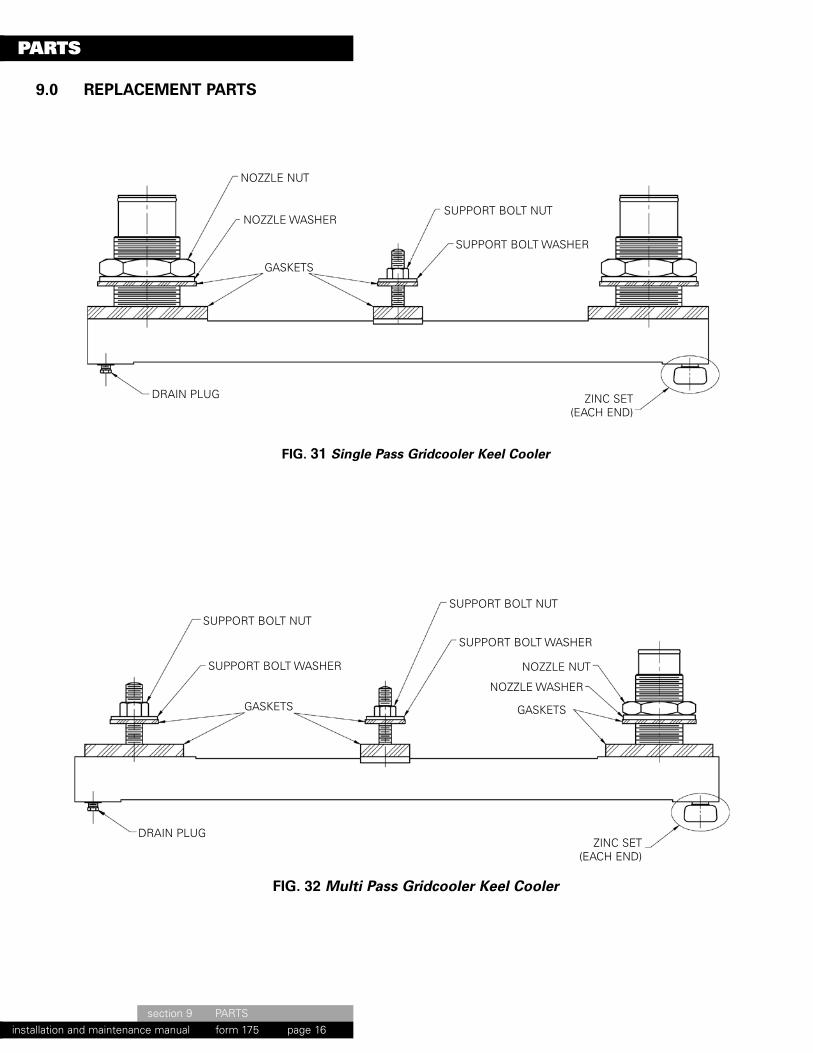
9.0 REPLACEMENT PARTS
section 9 PARTSinstallation and maintenance manual form 170 page 16
PARTS
DRAIN PLUG
SUPPORT BOLT NUT
SUPPORT BOLT NUT
NOZZLE NUT
NOZZLE WASHER
GASKETS
SUPPORT BOLT WASHER
GASKETS
SUPPORT BOLT WASHER
DRAIN PLUG
SUPPORT BOLT NUT
NOZZLE NUT
NOZZLE WASHER
GASKETS
SUPPORT BOLT WASHER
FIG. 31 Single Pass Gridcooler Keel Cooler
FIG. 32 Multi Pass Gridcooler Keel Cooler
ZINC SET(EACH END)
ZINC SET(EACH END)
Maintenance Manual 7/10/12 10:12 AM Page 20
form 175

section 9 PARTSinstallation and maintenance manual form 170 page 17
PARTS
NOTE: All gaskets are sold in a complete set. Sets includeall internal gaskets, exterior gaskets and isolators.
NOTE: Zincs are sold in sets consisting of two (2) zincanodes, four (4) mounting bolts and four (4)washers. One (1) Keel Cooler requires one (1) set.Keel Cooler model number is needed to identifycorrect set.
DRAIN PLUG
NOTE: Visit website for standard Keel Cooler replacementparts listed. www.fernstrum.comFor specials call factory direct.
FIG. 33 Z-Option Single Pass Gridcooler Keel Cooler
FIG. 34 Z-OPTION MULTI PASS GRIDCOOLER KEEL COOLER
SET SCREW
FLANGE GASKET
FLANGEINSULATOR
(NYLON)
FLANGE STUD BOLT
LOCKNUT
WASHERGASKET
SUPPORT PLATEINSULATOR
(NYLON)
STEEL FLANGE
DRAIN PLUG
SUPPORT PLATEINSULATOR
(NYLON)
GASKETS
FLANGE GASKET
FLANGEINSULATOR
(NYLON)
FLANGE STUD BOLT
LOCKNUT
WASHER
SET SCREW
STEEL FLANGE
ZINC SET(EACH END)
ZINC SET(EACH END)
Maintenance Manual 7/10/12 10:12 AM Page 21
form 175

section 10 WARRANTYinstallation and maintenance manual form 170 page 18
WARRANTY
10.0 LIMITED WARRANTY
The R.W. Fernstrum & Company, manufacturer, carefullytests and inspects each GRIDCOOLER® Keel Coolerbefore it leaves the point of manufacture. Themanufacturer makes no representations or warranties,express or implied, statutory or otherwise, except thoseherein expressly contained and shall not be held liable onany account except for repair or replacement under theterms following.
The manufacturer will, as to each GRIDCOOLER KeelCooler unit registered with it by the purchaser, repair orreplace free of charge, such Keel Cooler unit as is foundupon manufacturer’s inspection to be defective becauseof material or workmanship providing the same had beenreturned to the manufacturer’s factory, or a moreconvenient point as designated by the manufacturer,transportation prepaid, and received by the manufacturerwithin ninety (90) days from the date of delivery, withrespect to the aluminum GRIDCOOLER Keel Cooler, andwithin two (2) years with respect to the copper/nickelGRIDCOOLER Keel Cooler. The manufacturer’s obligationhereunder shall be limited to such time period and to thedirect cost of replacement and shall not include labortransportation, haul-out, launch, towing or storagecharges, mechanic travel time, inconvenience, loss oftime or income, removal and replacement and/ormodification of any boat parts to facilitate repairs or othersuch expenses incurred by purchaser.
This limited warranty shall not be effective with respectto GRIDCOOLER Keel Cooler to which repairs oralterations have been made unless authorized orperformed by the manufacturer, nor to defects arisingbecause of improper installation, misuse, accident orother causes beyond the control of the manufacturer.
Should any disputes arise with regard to their respectiverights, duties and responsibilities under the LimitedWarranty, all such disputes shall be governed by the lawsof the State of Michigan to the extent that the same donot conflict with the laws of the United States and anylitigation growing out of any such dispute shall becommenced in Circuit Court for Menominee County, inthe State of Michigan, U.S.A
PLEASE KEEP THIS FORM ON THE VESSEL FITTED WITH THE GRIDCOOLER UNITS.THE INFORMATION BELOW WILL BE OF USE FOR FUTURE REFERENCE.
ENGINE INFORMATION GRIDCOOLER INFORMATION
MAKE OF ENGINE MODEL OF ENGINEHP/RPM
(KW/RPM) QUANTITYMODEL OF GRIDCOOLER
Maintenance Manual 7/10/12 10:12 AM Page 22
form 175

section 11 RECOMMENDATION FORMinstallation and maintenance manual form 170 page 19
RECOMMENDATION FORM
ENGINE INFO
TYPE Propulsion � Bowthruster � Generator � Other
MANIFOLD Wet � Dry �Make
Model
HP & RPM
Heat Rejection
Fresh Water Flow Rate
Fresh Water Temp into Cooler
Fresh Water Temp Out or Drop Across Cooler
Minimum Hull Speed at Full Rated Power under full load) (If Speed is0 knots, or the engine is used as a generator size for 1/2 mph)
Maximum Sea Water Temp Engine Age % Antifreeze Used
Make & Model of Gear
Type of Boat (ferry, trawler, pleasure boat, etc.)
Hull Construction Steel � Fiberglass � Wood � Aluminum �Comments
CUSTOMER
PHONE
FAX
Date
Initials
� Drop� Out
� Painted� Unpainted
Maintenance Manual 7/10/12 10:12 AM Page 23
form 175

fernstrum.comPhone: 906.863.5553 • Fax: 906.863.5203 • Email: [email protected]
P.O. Box 97 • 1716 11th Avenue • Menominee, Michigan 49858 • USA
© 2013 R.W. Fernstrum & Company. All Rights Reserved. FERNSTRUM® and GRIDCOOLER® are registered trademarks of R.W. Fernstrum & Company.