grid generation for cfd analysis and design of a variety
TRANSCRIPT
designs
Article
Grid Generation for CFD Analysis and Design of aVariety of Twin Screw Machines
Sham Rane 1,2,*, Ahmed Kovacevic 1 and Nikola Stošic 1
1 Centre for Compressor Technology, City, University of London, London EC1V 0HB, UK;[email protected] (A.K.); [email protected] (N.S.)
2 Department of Engineering Science, University of Oxford, Oxford OX2 0ES, UK* Correspondence: [email protected]
Received: 28 May 2019; Accepted: 15 June 2019; Published: 25 June 2019�����������������
Abstract: A detailed study of the fluid flow and thermodynamic processes in positive displacementmachines requires 3D CFD modeling in order to capture their real geometry, including leakage gaps.However, limitations in the conventional computational grids, used in commercial software packages,exclude their use for classical twin screw machines. The screw compressor rotor grid generator(SCORG) is a customized grid generation tool developed to overcome these limitations. This papershows how it can be further extended to include non-conventional rotor designs, such as those withvariable lead or profile variation and even internally geared machines with conical rotors. Otherarrangements possible with this improvement include multiple gate rotors to increase volumetricdisplacement or dual lead, high wrap angle rotors for very high-pressure differences and vacuumapplications. A case study of a water-injected twin screw compressor is included to demonstrate itsuse for both detailed flow analysis and design.
Keywords: rotary screw machines; CFD; grid generation; screw compressor; screw expander; screwpump; variable geometry rotor
1. Introduction
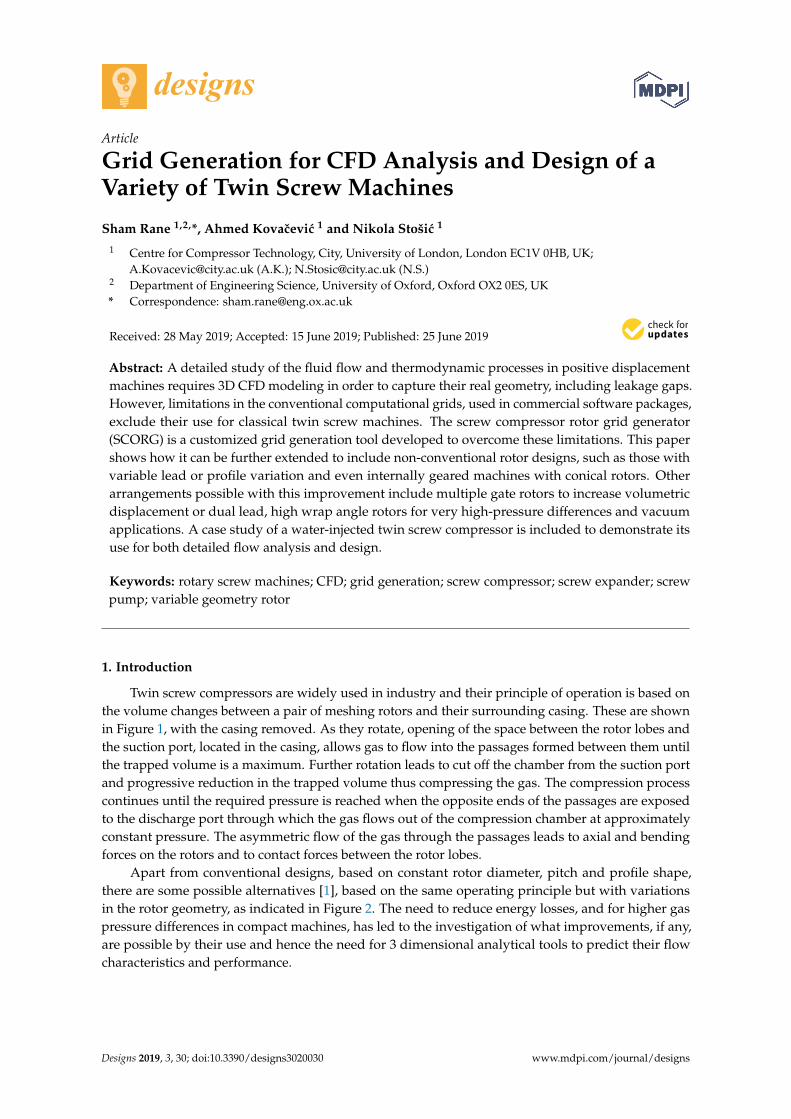
Twin screw compressors are widely used in industry and their principle of operation is based onthe volume changes between a pair of meshing rotors and their surrounding casing. These are shownin Figure 1, with the casing removed. As they rotate, opening of the space between the rotor lobes andthe suction port, located in the casing, allows gas to flow into the passages formed between them untilthe trapped volume is a maximum. Further rotation leads to cut off the chamber from the suction portand progressive reduction in the trapped volume thus compressing the gas. The compression processcontinues until the required pressure is reached when the opposite ends of the passages are exposedto the discharge port through which the gas flows out of the compression chamber at approximatelyconstant pressure. The asymmetric flow of the gas through the passages leads to axial and bendingforces on the rotors and to contact forces between the rotor lobes.
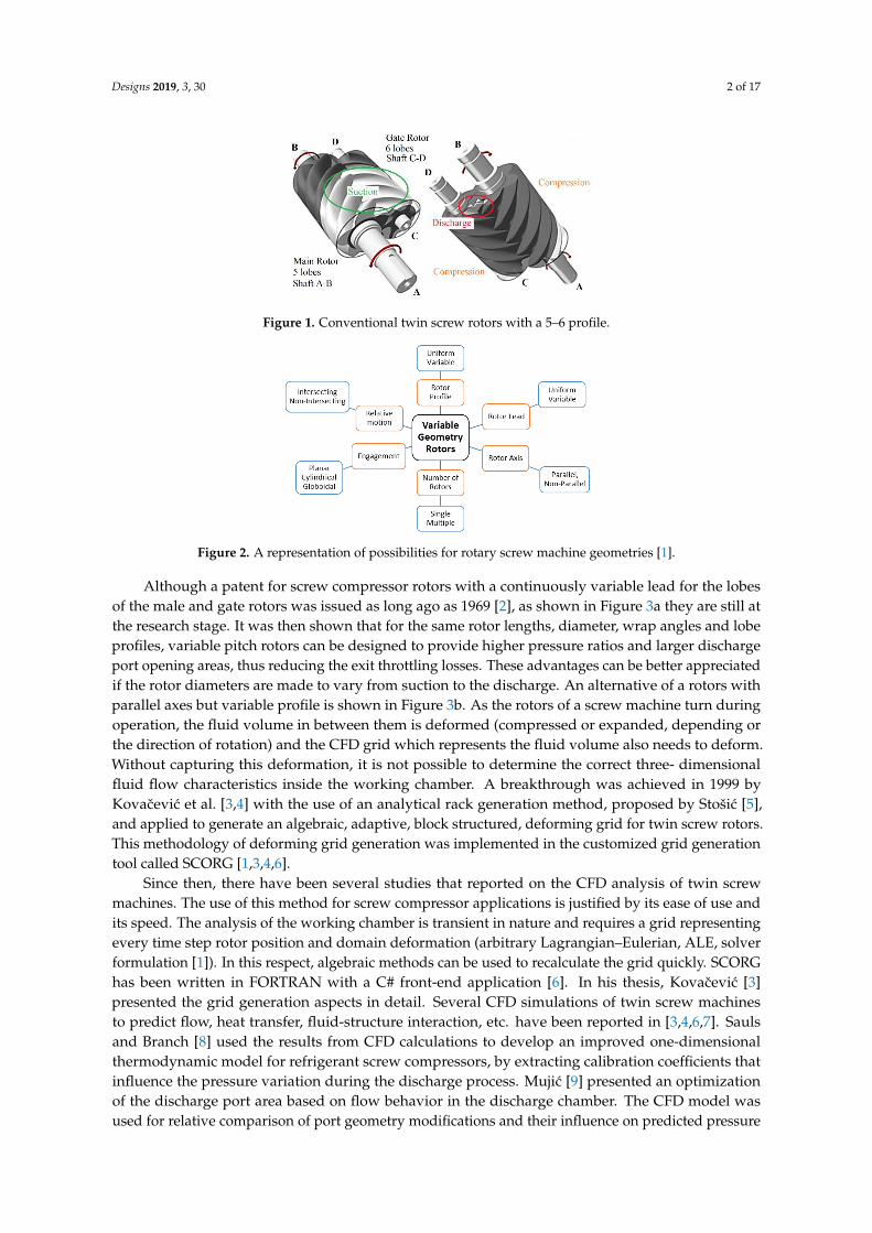
Apart from conventional designs, based on constant rotor diameter, pitch and profile shape,there are some possible alternatives [1], based on the same operating principle but with variationsin the rotor geometry, as indicated in Figure 2. The need to reduce energy losses, and for higher gaspressure differences in compact machines, has led to the investigation of what improvements, if any,are possible by their use and hence the need for 3 dimensional analytical tools to predict their flowcharacteristics and performance.
Designs 2019, 3, 30; doi:10.3390/designs3020030 www.mdpi.com/journal/designs
Designs 2019, 3, 30 2 of 17
Designs 2019, 3, x FOR PEER REVIEW 2 of 17
Figure 1. Conventional twin screw rotors with a 5–6 profile.
Figure 2. A representation of possibilities for rotary screw machine geometries [1].
Although a patent for screw compressor rotors with a continuously variable lead for the lobes
of the male and gate rotors was issued as long ago as 1969 [2], as shown in Figure 3a they are still at
the research stage. It was then shown that for the same rotor lengths, diameter, wrap angles and
lobe profiles, variable pitch rotors can be designed to provide higher pressure ratios and larger
discharge port opening areas, thus reducing the exit throttling losses. These advantages can be better
appreciated if the rotor diameters are made to vary from suction to the discharge. An alternative of a
rotors with parallel axes but variable profile is shown in Figure 3b. As the rotors of a screw machine
turn during operation, the fluid volume in between them is deformed (compressed or expanded,
depending or the direction of rotation) and the CFD grid which represents the fluid volume also
needs to deform. Without capturing this deformation, it is not possible to determine the correct three-
dimensional fluid flow characteristics inside the working chamber. A breakthrough was achieved in
1999 by Kovačević et al. [3,4] with the use of an analytical rack generation method, proposed by Stošić
[5], and applied to generate an algebraic, adaptive, block structured, deforming grid for twin screw
rotors. This methodology of deforming grid generation was implemented in the customized grid
generation tool called SCORG [1,3,4,6].
Since then, there have been several studies that reported on the CFD analysis of twin screw
machines. The use of this method for screw compressor applications is justified by its ease of use and
its speed. The analysis of the working chamber is transient in nature and requires a grid representing
every time step rotor position and domain deformation (arbitrary Lagrangian–Eulerian, ALE, solver
formulation [1]). In this respect, algebraic methods can be used to recalculate the grid quickly. SCORG
has been written in FORTRAN with a C# front-end application [6]. In his thesis, Kovačević [3]
presented the grid generation aspects in detail. Several CFD simulations of twin screw machines to
predict flow, heat transfer, fluid-structure interaction, etc. have been reported in [3,4,6,7]. Sauls and
Branch [8] used the results from CFD calculations to develop an improved one-dimensional
thermodynamic model for refrigerant screw compressors, by extracting calibration coefficients that
influence the pressure variation during the discharge process. Mujić [9] presented an optimization of
the discharge port area based on flow behavior in the discharge chamber. The CFD model was used
for relative comparison of port geometry modifications and their influence on predicted pressure
pulsations to judge the sound spectrum and noise level from the compressor. These noise levels
Figure 1. Conventional twin screw rotors with a 5–6 profile.
Designs 2019, 3, x FOR PEER REVIEW 2 of 17
Figure 1. Conventional twin screw rotors with a 5–6 profile.
Figure 2. A representation of possibilities for rotary screw machine geometries [1].
Although a patent for screw compressor rotors with a continuously variable lead for the lobes
of the male and gate rotors was issued as long ago as 1969 [2], as shown in Figure 3a they are still at
the research stage. It was then shown that for the same rotor lengths, diameter, wrap angles and
lobe profiles, variable pitch rotors can be designed to provide higher pressure ratios and larger
discharge port opening areas, thus reducing the exit throttling losses. These advantages can be better
appreciated if the rotor diameters are made to vary from suction to the discharge. An alternative of a
rotors with parallel axes but variable profile is shown in Figure 3b. As the rotors of a screw machine
turn during operation, the fluid volume in between them is deformed (compressed or expanded,
depending or the direction of rotation) and the CFD grid which represents the fluid volume also
needs to deform. Without capturing this deformation, it is not possible to determine the correct three-
dimensional fluid flow characteristics inside the working chamber. A breakthrough was achieved in
1999 by Kovačević et al. [3,4] with the use of an analytical rack generation method, proposed by Stošić
[5], and applied to generate an algebraic, adaptive, block structured, deforming grid for twin screw
rotors. This methodology of deforming grid generation was implemented in the customized grid
generation tool called SCORG [1,3,4,6].
Since then, there have been several studies that reported on the CFD analysis of twin screw
machines. The use of this method for screw compressor applications is justified by its ease of use and
its speed. The analysis of the working chamber is transient in nature and requires a grid representing
every time step rotor position and domain deformation (arbitrary Lagrangian–Eulerian, ALE, solver
formulation [1]). In this respect, algebraic methods can be used to recalculate the grid quickly. SCORG
has been written in FORTRAN with a C# front-end application [6]. In his thesis, Kovačević [3]
presented the grid generation aspects in detail. Several CFD simulations of twin screw machines to
predict flow, heat transfer, fluid-structure interaction, etc. have been reported in [3,4,6,7]. Sauls and
Branch [8] used the results from CFD calculations to develop an improved one-dimensional
thermodynamic model for refrigerant screw compressors, by extracting calibration coefficients that
influence the pressure variation during the discharge process. Mujić [9] presented an optimization of
the discharge port area based on flow behavior in the discharge chamber. The CFD model was used
for relative comparison of port geometry modifications and their influence on predicted pressure
pulsations to judge the sound spectrum and noise level from the compressor. These noise levels
Figure 2. A representation of possibilities for rotary screw machine geometries [1].
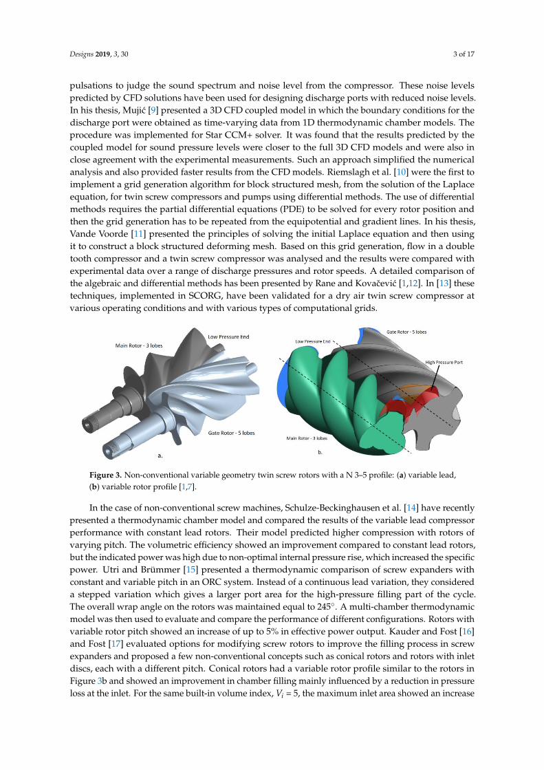
Although a patent for screw compressor rotors with a continuously variable lead for the lobesof the male and gate rotors was issued as long ago as 1969 [2], as shown in Figure 3a they are still atthe research stage. It was then shown that for the same rotor lengths, diameter, wrap angles and lobeprofiles, variable pitch rotors can be designed to provide higher pressure ratios and larger dischargeport opening areas, thus reducing the exit throttling losses. These advantages can be better appreciatedif the rotor diameters are made to vary from suction to the discharge. An alternative of a rotors withparallel axes but variable profile is shown in Figure 3b. As the rotors of a screw machine turn duringoperation, the fluid volume in between them is deformed (compressed or expanded, depending orthe direction of rotation) and the CFD grid which represents the fluid volume also needs to deform.Without capturing this deformation, it is not possible to determine the correct three- dimensionalfluid flow characteristics inside the working chamber. A breakthrough was achieved in 1999 byKovacevic et al. [3,4] with the use of an analytical rack generation method, proposed by Stošic [5],and applied to generate an algebraic, adaptive, block structured, deforming grid for twin screw rotors.This methodology of deforming grid generation was implemented in the customized grid generationtool called SCORG [1,3,4,6].
Since then, there have been several studies that reported on the CFD analysis of twin screwmachines. The use of this method for screw compressor applications is justified by its ease of use andits speed. The analysis of the working chamber is transient in nature and requires a grid representingevery time step rotor position and domain deformation (arbitrary Lagrangian–Eulerian, ALE, solverformulation [1]). In this respect, algebraic methods can be used to recalculate the grid quickly. SCORGhas been written in FORTRAN with a C# front-end application [6]. In his thesis, Kovacevic [3]presented the grid generation aspects in detail. Several CFD simulations of twin screw machinesto predict flow, heat transfer, fluid-structure interaction, etc. have been reported in [3,4,6,7]. Saulsand Branch [8] used the results from CFD calculations to develop an improved one-dimensionalthermodynamic model for refrigerant screw compressors, by extracting calibration coefficients thatinfluence the pressure variation during the discharge process. Mujic [9] presented an optimizationof the discharge port area based on flow behavior in the discharge chamber. The CFD model wasused for relative comparison of port geometry modifications and their influence on predicted pressure
Designs 2019, 3, 30 3 of 17
pulsations to judge the sound spectrum and noise level from the compressor. These noise levelspredicted by CFD solutions have been used for designing discharge ports with reduced noise levels.In his thesis, Mujic [9] presented a 3D CFD coupled model in which the boundary conditions for thedischarge port were obtained as time-varying data from 1D thermodynamic chamber models. Theprocedure was implemented for Star CCM+ solver. It was found that the results predicted by thecoupled model for sound pressure levels were closer to the full 3D CFD models and were also inclose agreement with the experimental measurements. Such an approach simplified the numericalanalysis and also provided faster results from the CFD models. Riemslagh et al. [10] were the first toimplement a grid generation algorithm for block structured mesh, from the solution of the Laplaceequation, for twin screw compressors and pumps using differential methods. The use of differentialmethods requires the partial differential equations (PDE) to be solved for every rotor position andthen the grid generation has to be repeated from the equipotential and gradient lines. In his thesis,Vande Voorde [11] presented the principles of solving the initial Laplace equation and then usingit to construct a block structured deforming mesh. Based on this grid generation, flow in a doubletooth compressor and a twin screw compressor was analysed and the results were compared withexperimental data over a range of discharge pressures and rotor speeds. A detailed comparison ofthe algebraic and differential methods has been presented by Rane and Kovacevic [1,12]. In [13] thesetechniques, implemented in SCORG, have been validated for a dry air twin screw compressor atvarious operating conditions and with various types of computational grids.
Designs 2019, 3, x FOR PEER REVIEW 3 of 17
predicted by CFD solutions have been used for designing discharge ports with reduced noise levels.
In his thesis, Mujić [9] presented a 3D CFD coupled model in which the boundary conditions for the
discharge port were obtained as time-varying data from 1D thermodynamic chamber models. The
procedure was implemented for Star CCM+ solver. It was found that the results predicted by the
coupled model for sound pressure levels were closer to the full 3D CFD models and were also in close
agreement with the experimental measurements. Such an approach simplified the numerical analysis
and also provided faster results from the CFD models. Riemslagh et al. [10] were the first to
implement a grid generation algorithm for block structured mesh, from the solution of the Laplace
equation, for twin screw compressors and pumps using differential methods. The use of differential
methods requires the partial differential equations (PDE) to be solved for every rotor position and
then the grid generation has to be repeated from the equipotential and gradient lines. In his thesis,
Vande Voorde [11] presented the principles of solving the initial Laplace equation and then using it
to construct a block structured deforming mesh. Based on this grid generation, flow in a double tooth
compressor and a twin screw compressor was analysed and the results were compared with
experimental data over a range of discharge pressures and rotor speeds. A detailed comparison of
the algebraic and differential methods has been presented by Rane and Kovačević [1,12]. In [13] these
techniques, implemented in SCORG, have been validated for a dry air twin screw compressor at
various operating conditions and with various types of computational grids.
Figure 3. Non-conventional variable geometry twin screw rotors with a N 3–5 profile: (a) variable
lead, (b) variable rotor profile [1,7].
In the case of non-conventional screw machines, Schulze-Beckinghausen et al. [14] have recently
presented a thermodynamic chamber model and compared the results of the variable lead
compressor performance with constant lead rotors. Their model predicted higher compression with
rotors of varying pitch. The volumetric efficiency showed an improvement compared to constant lead
rotors, but the indicated power was high due to non-optimal internal pressure rise, which increased
the specific power. Utri and Brümmer [15] presented a thermodynamic comparison of screw
expanders with constant and variable pitch in an ORC system. Instead of a continuous lead variation,
they considered a stepped variation which gives a larger port area for the high-pressure filling part
of the cycle. The overall wrap angle on the rotors was maintained equal to 245°. A multi-chamber
thermodynamic model was then used to evaluate and compare the performance of different
configurations. Rotors with variable rotor pitch showed an increase of up to 5% in effective power
output. Kauder and Fost [16] and Fost [17] evaluated options for modifying screw rotors to improve
the filling process in screw expanders and proposed a few non-conventional concepts such as conical
rotors and rotors with inlet discs, each with a different pitch. Conical rotors had a variable rotor
profile similar to the rotors in Figure 3b and showed an improvement in chamber filling mainly
influenced by a reduction in pressure loss at the inlet. For the same built-in volume index, 𝑉𝑖 = 5, the
maximum inlet area showed an increase from 540 to 1080 mm2. All these studies were done with the
intention of predicting the performance and characteristics of screw machines at the design stage and
optimizing the geometry and control parameters for a given application and operating condition. The
Figure 3. Non-conventional variable geometry twin screw rotors with a N 3–5 profile: (a) variable lead,(b) variable rotor profile [1,7].
In the case of non-conventional screw machines, Schulze-Beckinghausen et al. [14] have recentlypresented a thermodynamic chamber model and compared the results of the variable lead compressorperformance with constant lead rotors. Their model predicted higher compression with rotors ofvarying pitch. The volumetric efficiency showed an improvement compared to constant lead rotors,but the indicated power was high due to non-optimal internal pressure rise, which increased the specificpower. Utri and Brümmer [15] presented a thermodynamic comparison of screw expanders withconstant and variable pitch in an ORC system. Instead of a continuous lead variation, they considereda stepped variation which gives a larger port area for the high-pressure filling part of the cycle.The overall wrap angle on the rotors was maintained equal to 245◦. A multi-chamber thermodynamicmodel was then used to evaluate and compare the performance of different configurations. Rotors withvariable rotor pitch showed an increase of up to 5% in effective power output. Kauder and Fost [16]and Fost [17] evaluated options for modifying screw rotors to improve the filling process in screwexpanders and proposed a few non-conventional concepts such as conical rotors and rotors with inletdiscs, each with a different pitch. Conical rotors had a variable rotor profile similar to the rotors inFigure 3b and showed an improvement in chamber filling mainly influenced by a reduction in pressureloss at the inlet. For the same built-in volume index, Vi = 5, the maximum inlet area showed an increase

Designs 2019, 3, 30 4 of 17
from 540 to 1080 mm2. All these studies were done with the intention of predicting the performanceand characteristics of screw machines at the design stage and optimizing the geometry and controlparameters for a given application and operating condition. The use of Computational Fluid Dynamicsfor screw machine design is to be encouraged as it would provide better insight into the internal flowdynamics as a result of the vast improvements in computational technology and the availability ofmore accurate calculation methods. A CFD model of compressors with such non-conventional rotorshapes, was studied by the authors in [1,7,18]. In this paper, recent advances in the implementationof a differential grid [19,20], in the SCORG grid generator is demonstrated, using a PDE solution ofthe Poisson’s form. The quality of the numerical cells and their distribution is greatly improved bythis differential method making the grid suitable for multiphase models such as oil injected screwcompressors [21,22], (Video S2). A special procedure has been introduced that completely smoothsthe transition of the partitioning rack curve between the two rotors thus improving the grid nodemovement and the robustness of the CFD solver [20]. Further, applications of the SCORG tool areshown for a variety of screw machines such as variable geometry rotors with lead or profile variation,internally geared conical screw machines, multiple gate rotors and dual lead, high wrap angle rotors.A case study of a water-injected twin screw compressor [23] has been presented to demonstrate theuse of the developed grid generation tools in analysis and design.
2. SCORG—Customized Rotor CFD Grid Generation
An analytical grid generation of the screw machine working domain is explained inKovacevic et al. [3,4]. It includes separating domains of the screw rotors with a rack curve [5] andforming independent flow domains around each of the rotors. After the grid points are distributedon boundaries, an initial grid is obtained by trans-finite interpolation (TFI). Recently, in order toachieve a conformal single domain mesh, Rane and Kovacevic [12,13] introduced a new approach tobackground blocking. In this procedure, the outer boundary in each background block (Figure 4a),a coarse analytically generated mesh, is defined as a combination of the rack segment and the casingcircle segment. The rack segment stretches between the bottom and top cusp points and is closed bythe casing. The distribution obtained on the outer boundaries of the two blocks is used to constrain thedistribution on rotor profile as shown in Figure 4a.
Designs 2019, 3, x FOR PEER REVIEW 4 of 17
use of Computational Fluid Dynamics for screw machine design is to be encouraged as it would
provide better insight into the internal flow dynamics as a result of the vast improvements in
computational technology and the availability of more accurate calculation methods. A CFD model
of compressors with such non-conventional rotor shapes, was studied by the authors in [1,7,18]. In
this paper, recent advances in the implementation of a differential grid [19,20], in the SCORG grid
generator is demonstrated, using a PDE solution of the Poisson’s form. The quality of the numerical
cells and their distribution is greatly improved by this differential method making the grid suitable
for multiphase models such as oil injected screw compressors [21,22], (Video S2). A special procedure
has been introduced that completely smooths the transition of the partitioning rack curve between
the two rotors thus improving the grid node movement and the robustness of the CFD solver [20].
Further, applications of the SCORG tool are shown for a variety of screw machines such as variable
geometry rotors with lead or profile variation, internally geared conical screw machines, multiple
gate rotors and dual lead, high wrap angle rotors. A case study of a water-injected twin screw
compressor [23] has been presented to demonstrate the use of the developed grid generation tools in
analysis and design.
2. SCORG—Customized Rotor CFD Grid Generation
An analytical grid generation of the screw machine working domain is explained in Kovačević
et al. [3,4]. It includes separating domains of the screw rotors with a rack curve [5] and forming
independent flow domains around each of the rotors. After the grid points are distributed on
boundaries, an initial grid is obtained by trans-finite interpolation (TFI). Recently, in order to achieve
a conformal single domain mesh, Rane and Kovacevic [12,13] introduced a new approach to
background blocking. In this procedure, the outer boundary in each background block (Figure 4a), a
coarse analytically generated mesh, is defined as a combination of the rack segment and the casing
circle segment. The rack segment stretches between the bottom and top cusp points and is closed by
the casing. The distribution obtained on the outer boundaries of the two blocks is used to constrain
the distribution on rotor profile as shown in Figure 4a.
Figure 4. Background blocking used in SCORG for differential mesh.
The rack curve used to partition the two rotor domains, and the boundary distribution so
obtained, is shown in Figure 4b. This is employed to generate a 2D mesh using TFI. The blocking
approach then allows both a conformal and a non-conformal boundary map to produce a fully
hexahedral 3D grid. The nodes on the rack segment between the main and the gate rotor grids
together with a conformal boundary map are shown in Figure 4c. The 3D mesh generated from such
2D cross sections allows the rotor domains of the male and female rotors to be combined into a single
rotor mesh. This avoids inaccuracies and instabilities that may arise due to the interface mismatch in
a non-conformal boundary map. The resultant grids are recommended for oil injected multiphase
flow modelling and have been described in more detail by Rane and Kovacevic in [20,22] (Video S2).
However, even with this approach, during operation, as the rotors revolve, the rack curve comes to
a position when it changes with a relatively large deformation between two consecutive steps. The
algebraic method results in this transition as a step change at certain positions. One of the objectives
Figure 4. Background blocking used in SCORG for differential mesh.
The rack curve used to partition the two rotor domains, and the boundary distribution so obtained,is shown in Figure 4b. This is employed to generate a 2D mesh using TFI. The blocking approachthen allows both a conformal and a non-conformal boundary map to produce a fully hexahedral3D grid. The nodes on the rack segment between the main and the gate rotor grids together witha conformal boundary map are shown in Figure 4c. The 3D mesh generated from such 2D crosssections allows the rotor domains of the male and female rotors to be combined into a single rotormesh. This avoids inaccuracies and instabilities that may arise due to the interface mismatch in anon-conformal boundary map. The resultant grids are recommended for oil injected multiphase
Designs 2019, 3, 30 5 of 17
flow modelling and have been described in more detail by Rane and Kovacevic in [20,22] (Video S2).However, even with this approach, during operation, as the rotors revolve, the rack curve comes toa position when it changes with a relatively large deformation between two consecutive steps. Thealgebraic method results in this transition as a step change at certain positions. One of the objectives ofthe elliptic PDE mesh generation implemented in SCORG was to improve the time transition of thepartitioning rack curve between the two rotor domains.
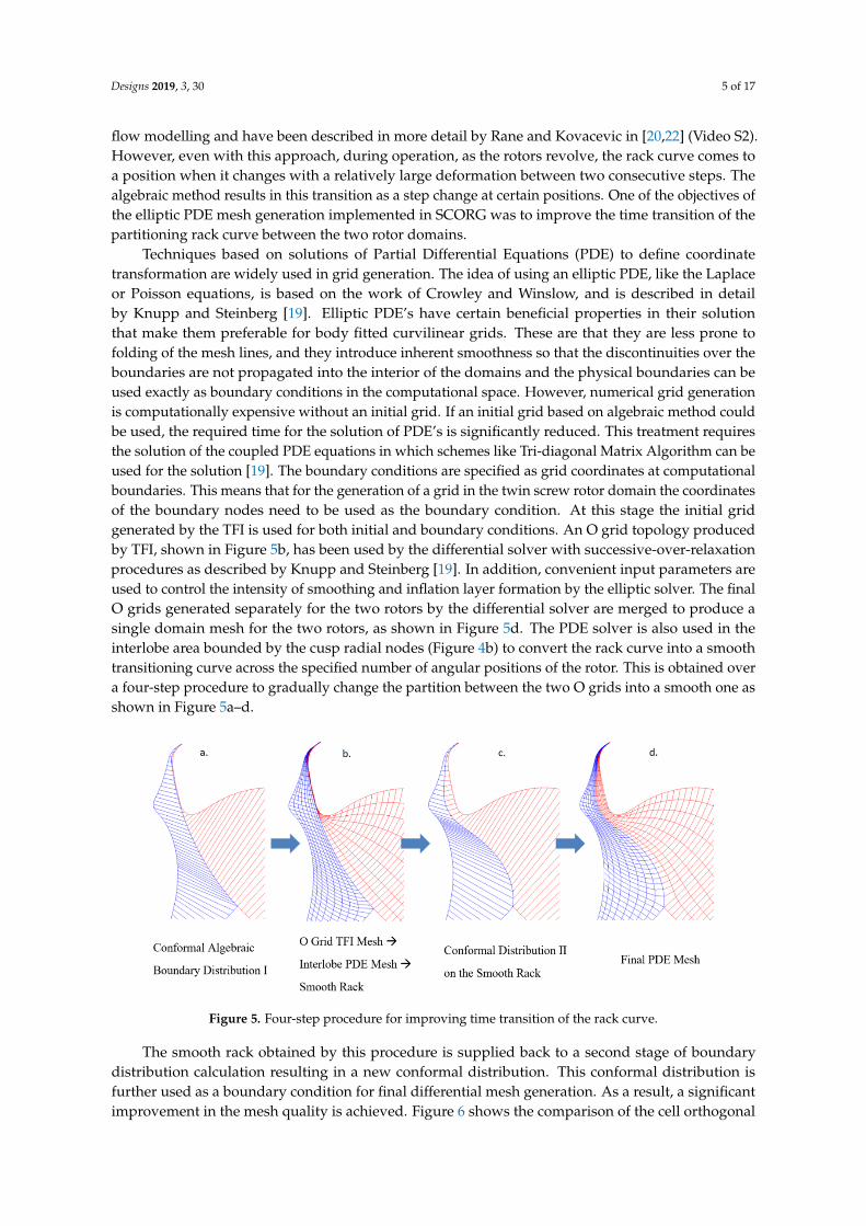
Techniques based on solutions of Partial Differential Equations (PDE) to define coordinatetransformation are widely used in grid generation. The idea of using an elliptic PDE, like the Laplaceor Poisson equations, is based on the work of Crowley and Winslow, and is described in detailby Knupp and Steinberg [19]. Elliptic PDE’s have certain beneficial properties in their solutionthat make them preferable for body fitted curvilinear grids. These are that they are less prone tofolding of the mesh lines, and they introduce inherent smoothness so that the discontinuities over theboundaries are not propagated into the interior of the domains and the physical boundaries can beused exactly as boundary conditions in the computational space. However, numerical grid generationis computationally expensive without an initial grid. If an initial grid based on algebraic method couldbe used, the required time for the solution of PDE’s is significantly reduced. This treatment requiresthe solution of the coupled PDE equations in which schemes like Tri-diagonal Matrix Algorithm can beused for the solution [19]. The boundary conditions are specified as grid coordinates at computationalboundaries. This means that for the generation of a grid in the twin screw rotor domain the coordinatesof the boundary nodes need to be used as the boundary condition. At this stage the initial gridgenerated by the TFI is used for both initial and boundary conditions. An O grid topology producedby TFI, shown in Figure 5b, has been used by the differential solver with successive-over-relaxationprocedures as described by Knupp and Steinberg [19]. In addition, convenient input parameters areused to control the intensity of smoothing and inflation layer formation by the elliptic solver. The finalO grids generated separately for the two rotors by the differential solver are merged to produce asingle domain mesh for the two rotors, as shown in Figure 5d. The PDE solver is also used in theinterlobe area bounded by the cusp radial nodes (Figure 4b) to convert the rack curve into a smoothtransitioning curve across the specified number of angular positions of the rotor. This is obtained overa four-step procedure to gradually change the partition between the two O grids into a smooth one asshown in Figure 5a–d.
Designs 2019, 3, x FOR PEER REVIEW 5 of 17
of the elliptic PDE mesh generation implemented in SCORG was to improve the time transition of
the partitioning rack curve between the two rotor domains.
Techniques based on solutions of Partial Differential Equations (PDE) to define coordinate
transformation are widely used in grid generation. The idea of using an elliptic PDE, like the Laplace
or Poisson equations, is based on the work of Crowley and Winslow, and is described in detail by
Knupp and Steinberg [19]. Elliptic PDE’s have certain beneficial properties in their solution that make
them preferable for body fitted curvilinear grids. These are that they are less prone to folding of the
mesh lines, and they introduce inherent smoothness so that the discontinuities over the boundaries
are not propagated into the interior of the domains and the physical boundaries can be used exactly
as boundary conditions in the computational space. However, numerical grid generation is
computationally expensive without an initial grid. If an initial grid based on algebraic method could
be used, the required time for the solution of PDE’s is significantly reduced. This treatment requires
the solution of the coupled PDE equations in which schemes like Tri-diagonal Matrix Algorithm can
be used for the solution [19]. The boundary conditions are specified as grid coordinates at
computational boundaries. This means that for the generation of a grid in the twin screw rotor
domain the coordinates of the boundary nodes need to be used as the boundary condition. At this
stage the initial grid generated by the TFI is used for both initial and boundary conditions. An O grid
topology produced by TFI, shown in Figure 5b, has been used by the differential solver with
successive-over-relaxation procedures as described by Knupp and Steinberg [19]. In addition,
convenient input parameters are used to control the intensity of smoothing and inflation layer
formation by the elliptic solver. The final O grids generated separately for the two rotors by the
differential solver are merged to produce a single domain mesh for the two rotors, as shown in Figure
5d. The PDE solver is also used in the interlobe area bounded by the cusp radial nodes (Figure 4b) to
convert the rack curve into a smooth transitioning curve across the specified number of angular
positions of the rotor. This is obtained over a four-step procedure to gradually change the partition
between the two O grids into a smooth one as shown in Figure 5(a–d).
Figure 5. Four-step procedure for improving time transition of the rack curve.
The smooth rack obtained by this procedure is supplied back to a second stage of boundary
distribution calculation resulting in a new conformal distribution. This conformal distribution is
further used as a boundary condition for final differential mesh generation. As a result, a significant
improvement in the mesh quality is achieved. Figure 6 shows the comparison of the cell orthogonal
quality between the algebraic meshes and the elliptic meshes. Figure 6(a–d) are algebraic meshes and
Figure 6(e–h) are elliptic meshes in the respective rotor positions. The algebraic method results in the
transition of the rack curve as a step change at certain positions as shown in Figures 6b and 6c.
Figure 5. Four-step procedure for improving time transition of the rack curve.
The smooth rack obtained by this procedure is supplied back to a second stage of boundarydistribution calculation resulting in a new conformal distribution. This conformal distribution isfurther used as a boundary condition for final differential mesh generation. As a result, a significantimprovement in the mesh quality is achieved. Figure 6 shows the comparison of the cell orthogonal

Designs 2019, 3, 30 6 of 17
quality between the algebraic meshes and the elliptic meshes. Figure 6a–d are algebraic meshes andFigure 6e–h are elliptic meshes in the respective rotor positions. The algebraic method results in thetransition of the rack curve as a step change at certain positions as shown in Figure 6b,c.Designs 2019, 3, x FOR PEER REVIEW 6 of 17
Figure 6. Comparison of cell orthogonal quality between algebraic (a–d) and elliptic (e–h) meshing.
The values for the minimum orthogonal angle of the algebraic meshes in Figure 6 (top) drop to
about 8 degrees after the rack curve transitions from position b to c. The majority of cells are in the
range 40–60 degrees orthogonality. Low orthogonality values are also noticed in position d. However,
in the case of elliptic meshing, the overall orthogonality has greatly improved so that the minimum
orthogonal angle is 25 degrees. Most of the cells are in the range 75–90 degrees orthogonality. There
is one cell at the bottom cusp which shows low orthogonality of about 15 degrees in both sets of
meshes, which is the consequence of the discontinuity at the cusp point and cannot be avoided.
However, the overall mesh quality is greatly improved. With these techniques, a good quality
quadrilateral cell structure can be constructed in the 2D cross sections of the rotor. Data from the 2D
cross sections is then combined to construct the full 3D grid representing the main and gate rotor
positions, and a set of such 3D grids needs to be generated with successive increments in the rotor
position and provided to the flow solver during numerical analysis [1].
2.1. Conventional Twin Screw Machine
Figure 7 shows the computational grid of a conventional twin screw machine. This example is
that of a water-injected twin screw compressor [23]. The case study analysis is presented in Section
3. SCORG generates a set of 2D cross sections with quadrilateral cells, as seen in one rotor profile
position in Figure 7. These sets of 2D sections are then assembled as 3D rotor domain grids, as seen
in Figure 7, for one rotor position. Several such 3D rotor node positions are produced by SCORG and
supplied to the flow solver during computations. A priori generation of 3D grid data for all the
cyclically repeating rotor positions ensures that the solver will function robustly (without failing due
to cell degeneration) during the simulation.
A choice of hexahedral structure allows for ease of re-use of the database, and at the same time
ALE formulations in the solver can be utilized that only demand accurate node positions with time
in order to capture grid deformation. Decomposition of the working chamber consists of splitting the
flow region into three main blocks as shown in Figure 7. This gives the flexibility to treat mesh
generation in these blocks independently, in the choice of the grid generation methods. In a single
domain mesh, both the rotors are contained in one deforming grid block thereby eliminating the non-
conformal interface between the rotors. The deforming rotor grid has non-conformal interfaces with
static ports and the water injection port.
Figure 6. Comparison of cell orthogonal quality between algebraic (a–d) and elliptic (e–h) meshing.
The values for the minimum orthogonal angle of the algebraic meshes in Figure 6 (top) drop toabout 8 degrees after the rack curve transitions from position b to c. The majority of cells are in therange 40–60 degrees orthogonality. Low orthogonality values are also noticed in position d. However,in the case of elliptic meshing, the overall orthogonality has greatly improved so that the minimumorthogonal angle is 25 degrees. Most of the cells are in the range 75–90 degrees orthogonality. There isone cell at the bottom cusp which shows low orthogonality of about 15 degrees in both sets of meshes,which is the consequence of the discontinuity at the cusp point and cannot be avoided. However,the overall mesh quality is greatly improved. With these techniques, a good quality quadrilateral cellstructure can be constructed in the 2D cross sections of the rotor. Data from the 2D cross sections isthen combined to construct the full 3D grid representing the main and gate rotor positions, and a set ofsuch 3D grids needs to be generated with successive increments in the rotor position and provided tothe flow solver during numerical analysis [1].
2.1. Conventional Twin Screw Machine
Figure 7 shows the computational grid of a conventional twin screw machine. This example isthat of a water-injected twin screw compressor [23]. The case study analysis is presented in Section 3.SCORG generates a set of 2D cross sections with quadrilateral cells, as seen in one rotor profile positionin Figure 7. These sets of 2D sections are then assembled as 3D rotor domain grids, as seen in Figure 7,for one rotor position. Several such 3D rotor node positions are produced by SCORG and supplied tothe flow solver during computations. A priori generation of 3D grid data for all the cyclically repeatingrotor positions ensures that the solver will function robustly (without failing due to cell degeneration)during the simulation.
A choice of hexahedral structure allows for ease of re-use of the database, and at the same timeALE formulations in the solver can be utilized that only demand accurate node positions with timein order to capture grid deformation. Decomposition of the working chamber consists of splittingthe flow region into three main blocks as shown in Figure 7. This gives the flexibility to treat meshgeneration in these blocks independently, in the choice of the grid generation methods. In a singledomain mesh, both the rotors are contained in one deforming grid block thereby eliminating the

Designs 2019, 3, 30 7 of 17
non-conformal interface between the rotors. The deforming rotor grid has non-conformal interfaceswith static ports and the water injection port.Designs 2019, 3, x FOR PEER REVIEW 7 of 17
Figure 7. Flow domain and rotor grid of a water-injected twin screw compressor [23].
2.2. Variable Lead Twin Screw Machine
Figure 3a shows the gearing of twin screw rotors with a variable helix lead. SCORG can be used
to generate the deforming rotor domain grid for such variable lead rotors [1,7]. A pitch variation
function is specified for the rotors and used to derive a relation between the fixed angular increments
from one section to the other, and the required variable axial displacements (Δz), for each cross
section of the rotor. Thus, the grid vertex data generated for one interlobe are reused but positioned
in the axial direction with variable Δz such that the pitch variation function gets applied. An example
rotor and the pitch function are shown in Figure 8, where the suction side pitch is 130 mm and the
discharge side pitch is 40 mm.
Figure 8. Variable lead screw rotor grid with 3/5 ‘N’ profile ([1,7], Video S1).
In [1], a comparative study was presented between uniform pitch (85 mm) with built in volume
index 𝑉𝑖 of 1.8 and 2.2, and those with a variable pitch with 𝑉𝑖 > 1.8 is shown in Figure 8. A wrap
angle of 285° was maintained for both the rotors, as shown in Figure 8. The analysis showed that by
varying the rotor lead continuously from the suction to the discharge ends, it is possible to achieve a
Figure 7. Flow domain and rotor grid of a water-injected twin screw compressor [23].
2.2. Variable Lead Twin Screw Machine
Figure 3a shows the gearing of twin screw rotors with a variable helix lead. SCORG can be usedto generate the deforming rotor domain grid for such variable lead rotors [1,7]. A pitch variationfunction is specified for the rotors and used to derive a relation between the fixed angular incrementsfrom one section to the other, and the required variable axial displacements (∆z), for each cross sectionof the rotor. Thus, the grid vertex data generated for one interlobe are reused but positioned in theaxial direction with variable ∆z such that the pitch variation function gets applied. An example rotorand the pitch function are shown in Figure 8, where the suction side pitch is 130 mm and the dischargeside pitch is 40 mm.
Designs 2019, 3, x FOR PEER REVIEW 7 of 17
Figure 7. Flow domain and rotor grid of a water-injected twin screw compressor [23].
2.2. Variable Lead Twin Screw Machine
Figure 3a shows the gearing of twin screw rotors with a variable helix lead. SCORG can be used
to generate the deforming rotor domain grid for such variable lead rotors [1,7]. A pitch variation
function is specified for the rotors and used to derive a relation between the fixed angular increments
from one section to the other, and the required variable axial displacements (Δz), for each cross
section of the rotor. Thus, the grid vertex data generated for one interlobe are reused but positioned
in the axial direction with variable Δz such that the pitch variation function gets applied. An example
rotor and the pitch function are shown in Figure 8, where the suction side pitch is 130 mm and the
discharge side pitch is 40 mm.
Figure 8. Variable lead screw rotor grid with 3/5 ‘N’ profile ([1,7], Video S1).
In [1], a comparative study was presented between uniform pitch (85 mm) with built in volume
index 𝑉𝑖 of 1.8 and 2.2, and those with a variable pitch with 𝑉𝑖 > 1.8 is shown in Figure 8. A wrap
angle of 285° was maintained for both the rotors, as shown in Figure 8. The analysis showed that by
varying the rotor lead continuously from the suction to the discharge ends, it is possible to achieve a
Figure 8. Variable lead screw rotor grid with 3/5 ‘N’ profile ([1,7], Video S1).

Designs 2019, 3, 30 8 of 17
In [1], a comparative study was presented between uniform pitch (85 mm) with built in volumeindex Vi of 1.8 and 2.2, and those with a variable pitch with Vi > 1.8 is shown in Figure 8. A wrap angleof 285◦ was maintained for both the rotors, as shown in Figure 8. The analysis showed that by varyingthe rotor lead continuously from the suction to the discharge ends, it is possible to achieve a steeperinternal pressure build up. Varying the rotor lead also allows a larger discharge port area, therebyreducing throttling losses, and an increase in volumetric efficiency (ηv) by reducing the sealing linelength in the high pressure zone. Uniform rotors show the highest volumetric efficiency at 2.0 bar.But with Vi = 2.2 the efficiency was lower than that of the variable pitch rotors due to a comparableinternal pressure rise and a comparatively shorter sealing line length. The variable lead rotors werefound to improve ηv by 2.2% at 2.0 bar and by 2.0% at 3.0 bar discharge pressure.
2.3. Variable Profile Twin Screw Machine
The SCORG grid generation algorithm was extended to variable profile rotors in [1]. The functionalityalso allows a covariation of rotor lead as well as rotor profile. An example of uniform lead and variableprofile rotor is shown in Figure 3b and the grid generated by SCORG is shown in Figure 9. In thisalgorithm, additional computational effort is required to calculate the 2D grid data in every crosssection as compared to that of a uniform pitch rotor grid generation calculation. The assembly of thegrid from a 2D to a 3D structure was completely redesigned in order to provide flexibility to generategrids for variable geometry rotors. The inputs for the geometry of the rotors can be provided as aset of profile coordinate files for the main and gate rotors in each cross section. These data pointscan be extracted from CAD models. In the case of profiles such as the ‘N’ profile which are definedby a generating rack, a set of rack coordinate files for each of the rotor cross section could be used.A comparative study between uniform profile and variable profile rotors has been presented in [1].In the case of the variable profile, the addendum on the suction end of the rotors was 33mm whileon the discharge side it was reduced to 21mm. The addendum on the uniform profile rotors had aconstant value 28.848mm. Due to variation of the addendum, the outer diameter of the male rotorchanges while the inner diameter remains constant and vice versa for the female rotor, as shown inFigure 9. The volumetric displacement of these rotors was smaller than that of the uniform profilerotors. Analysis of the variable profile rotors showed a steeper internal pressure rise but there was noreduction of the sealing line length and blow-hole area for the same size of rotors. The increase in rootdiameter of the female rotors with variable profile certainly helps in producing stiffer rotors for highpressure applications. There was not much gain in ηv at 3.0bar with the variable profile rotors due tothere being no significant reduction in the sealing line length.
Designs 2019, 3, x FOR PEER REVIEW 8 of 17
steeper internal pressure build up. Varying the rotor lead also allows a larger discharge port area,
thereby reducing throttling losses, and an increase in volumetric efficiency (𝜂𝑣) by reducing the
sealing line length in the high pressure zone. Uniform rotors show the highest volumetric efficiency
at 2.0 bar. But with 𝑉𝑖 = 2.2 the efficiency was lower than that of the variable pitch rotors due to a
comparable internal pressure rise and a comparatively shorter sealing line length. The variable lead
rotors were found to improve 𝜂𝑣 by 2.2% at 2.0 bar and by 2.0% at 3.0 bar discharge pressure.
2.3. Variable Profile Twin Screw Machine
The SCORG grid generation algorithm was extended to variable profile rotors in [1]. The
functionality also allows a covariation of rotor lead as well as rotor profile. An example of uniform
lead and variable profile rotor is shown in Figure 3b and the grid generated by SCORG is shown in
Figure 9. In this algorithm, additional computational effort is required to calculate the 2D grid data
in every cross section as compared to that of a uniform pitch rotor grid generation calculation. The
assembly of the grid from a 2D to a 3D structure was completely redesigned in order to provide
flexibility to generate grids for variable geometry rotors. The inputs for the geometry of the rotors
can be provided as a set of profile coordinate files for the main and gate rotors in each cross section.
These data points can be extracted from CAD models. In the case of profiles such as the ‘N’ profile
which are defined by a generating rack, a set of rack coordinate files for each of the rotor cross section
could be used. A comparative study between uniform profile and variable profile rotors has been
presented in [1]. In the case of the variable profile, the addendum on the suction end of the rotors
was 33mm while on the discharge side it was reduced to 21mm. The addendum on the uniform
profile rotors had a constant value 28.848mm. Due to variation of the addendum, the outer diameter
of the male rotor changes while the inner diameter remains constant and vice versa for the female
rotor, as shown in Figure 9. The volumetric displacement of these rotors was smaller than that of the
uniform profile rotors. Analysis of the variable profile rotors showed a steeper internal pressure rise
but there was no reduction of the sealing line length and blow-hole area for the same size of rotors.
The increase in root diameter of the female rotors with variable profile certainly helps in producing
stiffer rotors for high pressure applications. There was not much gain in 𝜂𝑣 at 3.0bar with the
variable profile rotors due to there being no significant reduction in the sealing line length.
Figure 9. Variable profile screw rotor grid with 3/5 ‘N’ profile [1,7].
A 1.2% reduction in 𝜂𝑣 was observed at 2.0 bar due to the smaller capacity of the machine and
the higher internal pressure rise resulting in over-compression. The uniform rotors show the highest
adiabatic efficiency (𝜂𝑎 ) at 2.0 bar. However, with 𝑉𝑖 = 2.2 their 𝜂𝑎 was lower than that of the
variable geometry rotors. At 3.0 bar, the uniform rotors have a reduced adiabatic efficiency, but this
is still 0.7% higher than that of the variable geometry rotors. Both the variable pitch and the variable
Figure 9. Variable profile screw rotor grid with 3/5 ‘N’ profile [1,7].
Designs 2019, 3, 30 9 of 17
A 1.2% reduction in ηv was observed at 2.0 bar due to the smaller capacity of the machine andthe higher internal pressure rise resulting in over-compression. The uniform rotors show the highestadiabatic efficiency (ηa) at 2.0 bar. However, with Vi = 2.2 their ηa was lower than that of the variablegeometry rotors. At 3.0 bar, the uniform rotors have a reduced adiabatic efficiency, but this is still 0.7%higher than that of the variable geometry rotors. Both the variable pitch and the variable profile rotorsshow an increment in adiabatic efficiency due to a balanced internal pressure rise. The improvementwas found to be 2.8% at 2.0 bar and 1.0% at 3.0 bar with the variable lead rotors and 1.1% at bothpressures with the variable profile rotors.
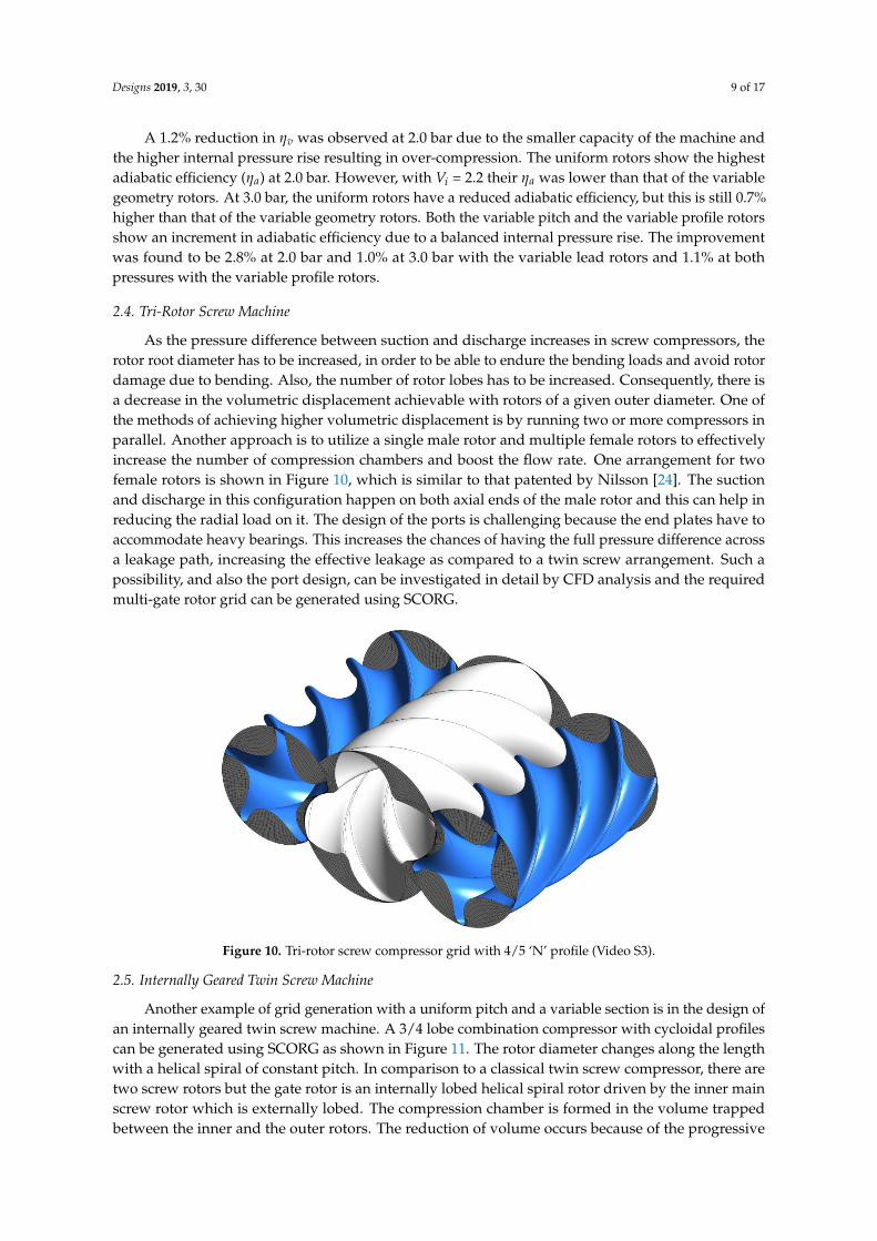
2.4. Tri-Rotor Screw Machine
As the pressure difference between suction and discharge increases in screw compressors, therotor root diameter has to be increased, in order to be able to endure the bending loads and avoid rotordamage due to bending. Also, the number of rotor lobes has to be increased. Consequently, there isa decrease in the volumetric displacement achievable with rotors of a given outer diameter. One ofthe methods of achieving higher volumetric displacement is by running two or more compressors inparallel. Another approach is to utilize a single male rotor and multiple female rotors to effectivelyincrease the number of compression chambers and boost the flow rate. One arrangement for twofemale rotors is shown in Figure 10, which is similar to that patented by Nilsson [24]. The suctionand discharge in this configuration happen on both axial ends of the male rotor and this can help inreducing the radial load on it. The design of the ports is challenging because the end plates have toaccommodate heavy bearings. This increases the chances of having the full pressure difference acrossa leakage path, increasing the effective leakage as compared to a twin screw arrangement. Such apossibility, and also the port design, can be investigated in detail by CFD analysis and the requiredmulti-gate rotor grid can be generated using SCORG.
Designs 2019, 3, x FOR PEER REVIEW 9 of 17
profile rotors show an increment in adiabatic efficiency due to a balanced internal pressure rise. The
improvement was found to be 2.8% at 2.0 bar and 1.0% at 3.0 bar with the variable lead rotors and
1.1% at both pressures with the variable profile rotors.
2.4. Tri-Rotor Screw Machine
As the pressure difference between suction and discharge increases in screw compressors, the
rotor root diameter has to be increased, in order to be able to endure the bending loads and avoid
rotor damage due to bending. Also, the number of rotor lobes has to be increased. Consequently,
there is a decrease in the volumetric displacement achievable with rotors of a given outer diameter.
One of the methods of achieving higher volumetric displacement is by running two or more
compressors in parallel. Another approach is to utilize a single male rotor and multiple female rotors
to effectively increase the number of compression chambers and boost the flow rate. One
arrangement for two female rotors is shown in Figure 10, which is similar to that patented by Nilsson
[24]. The suction and discharge in this configuration happen on both axial ends of the male rotor and
this can help in reducing the radial load on it. The design of the ports is challenging because the end
plates have to accommodate heavy bearings. This increases the chances of having the full pressure
difference across a leakage path, increasing the effective leakage as compared to a twin screw
arrangement. Such a possibility, and also the port design, can be investigated in detail by CFD
analysis and the required multi-gate rotor grid can be generated using SCORG.
Figure 10. Tri-rotor screw compressor grid with 4/5 ‘N’ profile (Video S3).
2.5. Internally Geared Twin Screw Machine
Another example of grid generation with a uniform pitch and a variable section is in the design
of an internally geared twin screw machine. A 3/4 lobe combination compressor with cycloidal
profiles can be generated using SCORG as shown in Figure 11. The rotor diameter changes along the
length with a helical spiral of constant pitch. In comparison to a classical twin screw compressor,
there are two screw rotors but the gate rotor is an internally lobed helical spiral rotor driven by the
inner main screw rotor which is externally lobed. The compression chamber is formed in the volume
trapped between the inner and the outer rotors. The reduction of volume occurs because of the
progressive reduction of the rotor diameter due to scaling of the profile along the spiral. This in turn
causes internal compression and increase in pressure. In operation, the outer rotor is positioned on a
central axis while the inner rotor rotates about an eccentric axis with varying centre distance from the
suction to the discharge ends. Both axes are stationary in space.
Figure 10. Tri-rotor screw compressor grid with 4/5 ‘N’ profile (Video S3).
2.5. Internally Geared Twin Screw Machine
Another example of grid generation with a uniform pitch and a variable section is in the design ofan internally geared twin screw machine. A 3/4 lobe combination compressor with cycloidal profilescan be generated using SCORG as shown in Figure 11. The rotor diameter changes along the lengthwith a helical spiral of constant pitch. In comparison to a classical twin screw compressor, there aretwo screw rotors but the gate rotor is an internally lobed helical spiral rotor driven by the inner mainscrew rotor which is externally lobed. The compression chamber is formed in the volume trappedbetween the inner and the outer rotors. The reduction of volume occurs because of the progressive

Designs 2019, 3, 30 10 of 17
reduction of the rotor diameter due to scaling of the profile along the spiral. This in turn causes internalcompression and increase in pressure. In operation, the outer rotor is positioned on a central axis whilethe inner rotor rotates about an eccentric axis with varying centre distance from the suction to thedischarge ends. Both axes are stationary in space.Designs 2019, 3, x FOR PEER REVIEW 10 of 17
Figure 11. Grid of the working chamber of conical internally geared screw rotors ([1], Video S4).
2.6. Dual Lead Twin Screw Machine
In liquid pumping application with a very high pressure difference between suction and
discharge, or in vacuum pumps, a conventional screw rotor has a very high wrap angle of the order
of 1080º. In comparison, a twin screw compressor has a wrap angle in the range of 250o–310º. The
large wrap angle severely reduces the volumetric capacity of such pump rotors. One of the means of
increasing displacement is to use a dual lead rotor as shown in Figure 12. SCORG can generate a rotor
grid for such high wrap angle rotors and can construct dual/multiple lead sections.
Figure 12. Grid of the working chamber of dual lead, high wrap angle, screw pump rotors.
3. Application of SCORG Grid for Analysis of Water-Injected Twin Screw Compressor
There are industrial processes requiring clean compressed air where oil contamination is not
acceptable such as in food and pharmacy plants. In the absence of oil in the compression chamber,
leakage and thermal deformation significantly limit the delivery pressures that can be achieved in
one compression stage. Accordingly, multistage compression with intercooling has been employed
which adds immensely to the cost of the compressor plant. Injection of liquid water into twin screw
air compressors has been pursued for a long time to gain thermodynamic benefits over dry air
compression. When water is used in small quantities during the compression process, internal
Figure 11. Grid of the working chamber of conical internally geared screw rotors ([1], Video S4).
2.6. Dual Lead Twin Screw Machine
In liquid pumping application with a very high pressure difference between suction and discharge,or in vacuum pumps, a conventional screw rotor has a very high wrap angle of the order of 1080o.In comparison, a twin screw compressor has a wrap angle in the range of 250◦–310◦. The large wrapangle severely reduces the volumetric capacity of such pump rotors. One of the means of increasingdisplacement is to use a dual lead rotor as shown in Figure 12. SCORG can generate a rotor grid forsuch high wrap angle rotors and can construct dual/multiple lead sections.
Designs 2019, 3, x FOR PEER REVIEW 10 of 17
Figure 11. Grid of the working chamber of conical internally geared screw rotors ([1], Video S4).
2.6. Dual Lead Twin Screw Machine
In liquid pumping application with a very high pressure difference between suction and
discharge, or in vacuum pumps, a conventional screw rotor has a very high wrap angle of the order
of 1080º. In comparison, a twin screw compressor has a wrap angle in the range of 250o–310º. The
large wrap angle severely reduces the volumetric capacity of such pump rotors. One of the means of
increasing displacement is to use a dual lead rotor as shown in Figure 12. SCORG can generate a rotor
grid for such high wrap angle rotors and can construct dual/multiple lead sections.
Figure 12. Grid of the working chamber of dual lead, high wrap angle, screw pump rotors.
3. Application of SCORG Grid for Analysis of Water-Injected Twin Screw Compressor
There are industrial processes requiring clean compressed air where oil contamination is not
acceptable such as in food and pharmacy plants. In the absence of oil in the compression chamber,
leakage and thermal deformation significantly limit the delivery pressures that can be achieved in
one compression stage. Accordingly, multistage compression with intercooling has been employed
which adds immensely to the cost of the compressor plant. Injection of liquid water into twin screw
air compressors has been pursued for a long time to gain thermodynamic benefits over dry air
compression. When water is used in small quantities during the compression process, internal
Figure 12. Grid of the working chamber of dual lead, high wrap angle, screw pump rotors.
Designs 2019, 3, 30 11 of 17
3. Application of SCORG Grid for Analysis of Water-Injected Twin Screw Compressor
There are industrial processes requiring clean compressed air where oil contamination is notacceptable such as in food and pharmacy plants. In the absence of oil in the compression chamber,leakage and thermal deformation significantly limit the delivery pressures that can be achieved inone compression stage. Accordingly, multistage compression with intercooling has been employedwhich adds immensely to the cost of the compressor plant. Injection of liquid water into twin screw aircompressors has been pursued for a long time to gain thermodynamic benefits over dry air compression.When water is used in small quantities during the compression process, internal cooling and sealingcan be achieved while a condenser fitted downstream of the compressor can strain the water out of thedelivered high pressure air. In such a system or when there are no condensers employed it is desirableto inject an optimum quantity of water into the compression chamber to gain evaporative cooling.Recent studies have shown that using CFD models for dry air and oil injected air compressors achieveda good agreement with measurements, in the prediction of performance parameters [22]. In thesesimulations, Eulerian-Eulerian multiphase modelling has been applied. Implementation of the samemodel for water injected compressors presents an additional challenge in that the liquid water injectedinto the compression chamber changes phase and evaporates depending on local saturation andthermodynamic conditions [23]. Water also forms a liquid film on the rotor and housing and therebyinfluences thermal changes. The objective of the present analysis was to estimate the temperaturedistribution inside the compressor, identify non-uniformity and provide data to estimate thermaldeformation due to high temperatures. A CFD model was used to calculate four different operatingconditions with gradually increasing water content. The analysis indicates that with an increasedamount of water injection into the compression chamber it is possible to control the gas dischargetemperature within the limit of 200 ◦C to ensure the safe operation of the bearings and seals.
3.1. CFD Model and Operating Conditions
A detailed description of typical CFD modeling for twin screw compressors is presented inRane [1,12,13]. The whole working domain of the compressor was split into four main sub-domains,namely the rotor domain, the suction port, the discharge end leakage gap and the discharge port.All the sub-domains were connected in the solver by non-conformal interfaces. The grid for the rotordomain was generated using SCORG while grids for all stationary domains were obtained usingANSYS meshing. The ANSYS CFX solver was used in this study. Inhomogeneous formulation treatsmomentum transport for each phase separately and can account for high slip conditions. Evaporationof the water-liquid phase is defined as per Equation (1) and the saturation temperature Tsat,p = 184.06◦C is specified with latent heat L = 1998.55 kJ/kg in Equation (2) corresponding to 11.0 bar deliverypressure. An empirical form of the Lee model [23] has been used in the present study. It is assumed thatduring the entire compression process from suction pressure to discharge pressure, secondary phasewater-liquid changes phase to water-vapour only when its temperature Tw exceeds the saturationtemperature at a discharge pressure corresponding to Tsat,p_d. Such high temperatures can occurinside the compression chamber due to the heat addition of compression and reheating of the leakagegas. Possible internal over-compression is another contributor. Another crude assumption is that thephase change is unidirectional i.e., only evaporation occurs and no condensation. It is anticipated thatcondensation if it has to occur will happen in the discharge pipes and not in the compression chamberwhere continuous heat addition occurs. As the discharge piping is not a part of the computationaldomain, condensation can be ignored. Once the water-liquid is evaporated it is artificially removedfrom the domain. The entire enthalpy of evaporation is extracted from the primary phase air resultingin its cooling. In empirical form the evaporation mass transfer rate for water-liquid phase is

Designs 2019, 3, 30 12 of 17
If Tw > Tsat,p_d (Evaporation)
.mwv = ce αwρw
(Tw−Tsat,p
Tsat,p
)Lee Model
.mwv = −c′e αwρw Empirical form
(1)
Such that, Tw � Tsat,p
c′e = ce
(Tw − Tsat,p
Tsat,p
)=
1∆t
The enthalpy source in energy equation applied for air phase is defined as
Qva = −.
mwv·L (2)
where L is the latent heat due to evaporation at discharge pressure. Such an empirical model alsoenables the use of constant thermodynamic properties for the water-liquid in the calculations. Fourcases were calculated in this study. The corresponding operating conditions are as shown in Table 1.
Table 1. Evaluated CFD cases and resultant discharge temperatures at 11.0 bar.
Speed (rpm) Water (kg/s) Remark Average Discharge Temperature (◦C)
Case1 6000 0.018 Twice the saturation mass 325Case2 4500 0.009 Saturation mass 262Case3 4500 0.045 Five times the saturation mass 205Case4 6000 0.090 Ten times the saturation mass 187
The fluid properties are defined in Table 2 with air as the primary phase and water-liquid as thesecondary phase. Pressure boundary conditions were specified at the suction and discharge. Solverparameters were set at higher stability conditions. The SST k-Omega turbulence model was applied.Results from CFD analysis are presented in this section. They reflect a state when full 11.0 bar dischargepressure has been reached in the discharge port and 1–2 cycles of calculation were continued at theseoperating conditions. The cycle averaged temperature data were collected during the simulation.
Table 2. Fluid properties.
Property Air Water Liquid Units
Density Ideal GasLaw 997.0 Kg/m3
Dynamic Viscosity 1.83 × 10⁻⁵ 8.889 × 10⁻⁴ Kg/m-sThermal Conductivity 2.61 × 10⁻² 0.6069 W/m-KSpecific heat capacity 1004.4 4181.7 J/kg-K
3.2. Internal Compression Chamber Pressure
Figure 13 shows the rise of pressure in the compression chamber with main rotor rotation forCase1 at 6000 rpm and 0.018 kg/s water mass flow rate condition. Both air and water are at the samepressure inside the chamber. Because of the high under-compression which can be observed by thesteep pressure rise at 350◦ rotor angle, a strong pressure pulse is generated in the discharge port.

Designs 2019, 3, 30 13 of 17
Designs 2019, 3, x FOR PEER REVIEW 12 of 17
𝑄𝑣𝑎 = −��𝑤𝑣 ∙ 𝐿 (2)
where 𝐿 is the latent heat due to evaporation at discharge pressure. Such an empirical model also
enables the use of constant thermodynamic properties for the water-liquid in the calculations. Four
cases were calculated in this study. The corresponding operating conditions are as shown in Table 1.
Table 1. Evaluated CFD cases and resultant discharge temperatures at 11.0 bar.
Speed
(rpm)
Water
(kg/s) Remark Average Discharge Temperature (℃)
Case1 6000 0.018 Twice the saturation mass 325
Case2 4500 0.009 Saturation mass 262
Case3 4500 0.045 Five times the saturation mass 205
Case4 6000 0.090 Ten times the saturation mass 187
The fluid properties are defined in Table 2 with air as the primary phase and water-liquid as the
secondary phase. Pressure boundary conditions were specified at the suction and discharge. Solver
parameters were set at higher stability conditions. The SST k-Omega turbulence model was applied.
Results from CFD analysis are presented in this section. They reflect a state when full 11.0 bar
discharge pressure has been reached in the discharge port and 1–2 cycles of calculation were
continued at these operating conditions. The cycle averaged temperature data were collected during
the simulation.
Table 2. Fluid properties.
Property Air Water Liquid Units
Density Ideal Gas Law 997.0 Kg/m3
Dynamic Viscosity 1.83 × 10⁻⁵ 8.889 × 10⁻⁴ Kg/m-s
Thermal Conductivity 2.61 × 10⁻² 0.6069 W/m-K
Specific heat capacity 1004.4 4181.7 J/kg-K
3.2. Internal Compression Chamber Pressure
Figure 13 shows the rise of pressure in the compression chamber with main rotor rotation for
Case1 at 6000 rpm and 0.018 kg/s water mass flow rate condition. Both air and water are at the same
pressure inside the chamber. Because of the high under-compression which can be observed by the
steep pressure rise at 350° rotor angle, a strong pressure pulse is generated in the discharge port.
Figure 13. Internal chamber pressure variation during a compression cycle.
The indicated power at 6000 rpm was 21.0 kW and at 4500 rpm it was 15.0 kW. The average
torque on the main rotor was close to 30.0 Nm while that on the gate rotor was close to 3.69 Nm. The
direction of gate rotor torque was opposite to that of the main rotor. All four cases were calculated at
11.0 bar discharge pressure and the resultant rotor torque was in a similar range in all cases.
Figure 13. Internal chamber pressure variation during a compression cycle.
The indicated power at 6000 rpm was 21.0 kW and at 4500 rpm it was 15.0 kW. The average torqueon the main rotor was close to 30.0 Nm while that on the gate rotor was close to 3.69 Nm. The directionof gate rotor torque was opposite to that of the main rotor. All four cases were calculated at 11.0 bardischarge pressure and the resultant rotor torque was in a similar range in all cases.
3.3. Gas Temperature Distribution
If water was not injected into the compressor, the air temperature would have exceeded 380 ◦C at11.0 bar discharge pressure. In the analysed cases, water was injected at 10 ◦C. Table 1 presents theaverage air temperature at discharge in the four cases. It can be observed that for a low water massflow rate of 0.009 kg/s the cooling effect was stronger in Case 2 at 4500 rpm compared to Case 1 at6000 rpm, which had twice the water mass flow compared to Case 2.
A water mass of 0.009 kg/s was determined so as to achieve saturated air at the exit with powerdissipation of approximately 30 kW. But these estimates did not account for transient effects. The CFDcalculation therefore resulted in higher than saturation exit temperatures. Additionally, leakage of gasduring compression adds to the accumulation of energy in the compression chamber which furtherraises the gas temperature. Cases 2 and 4 were designed so that the mass flow rate of water is 5 and10 times that of the saturation mass of Case 2, respectively, with the aim of achieving a dischargetemperature lower than 200 ◦C . The limit of 200 ◦C is due to the maximum temperature that thecompressor bearings and housing can withstand during operation. It can be observed from Table 1 thatthe temperature of 205 ◦C is achieved at 4500 rpm and 187 ◦C is achieved at 6000 rpm with increasedmass flow of water. Figure 14 presents the distribution of air temperature inside the compressor.An iso-surface generated with a water-liquid volume fraction of 0.01% is also shown in the figure.The air temperature in the suction port is lower on the gate rotor side, but on the main rotor side itis higher. This indicates that the leakage is higher from the tip of the main rotor than that from thegate rotor and also that the cooling is more effective on the gate rotor side than on the main rotor sidefor the same mass of injected water. The temperature on the gate rotor is higher than on the mainrotor close to the discharge port. Water-liquid is observed in the region where the air temperatureis below the saturation temperature at 11.0 bar. An evaporation effect is visible in the compressionchamber opened to the discharge port and also in the discharge port, i.e., no liquid water is presentthere. In comparison to Case 2, Case3 resulted in about 50 ◦C lower cycle averaged temperature.

Designs 2019, 3, 30 14 of 17
Designs 2019, 3, x FOR PEER REVIEW 13 of 17
3.3. Gas Temperature Distribution
If water was not injected into the compressor, the air temperature would have exceeded 380 °C
at 11.0 bar discharge pressure. In the analysed cases, water was injected at 10 °C. Table 1 presents the
average air temperature at discharge in the four cases. It can be observed that for a low water mass
flow rate of 0.009 kg/s the cooling effect was stronger in Case 2 at 4500 rpm compared to Case 1 at
6000 rpm, which had twice the water mass flow compared to Case 2.
A water mass of 0.009 kg/s was determined so as to achieve saturated air at the exit with power
dissipation of approximately 30 kW. But these estimates did not account for transient effects. The
CFD calculation therefore resulted in higher than saturation exit temperatures. Additionally, leakage
of gas during compression adds to the accumulation of energy in the compression chamber which
further raises the gas temperature. Cases 2 and 4 were designed so that the mass flow rate of water
is 5 and 10 times that of the saturation mass of Case 2, respectively, with the aim of achieving a
discharge temperature lower than 200 ℃. The limit of 200 ℃ is due to the maximum temperature that
the compressor bearings and housing can withstand during operation. It can be observed from Table
1 that the temperature of 205 ℃ is achieved at 4500 rpm and 187 ℃ is achieved at 6000 rpm with
increased mass flow of water. Figure 14 presents the distribution of air temperature inside the
compressor. An iso-surface generated with a water-liquid volume fraction of 0.01% is also shown in
the figure. The air temperature in the suction port is lower on the gate rotor side, but on the main
rotor side it is higher. This indicates that the leakage is higher from the tip of the main rotor than that
from the gate rotor and also that the cooling is more effective on the gate rotor side than on the main
rotor side for the same mass of injected water. The temperature on the gate rotor is higher than on
the main rotor close to the discharge port. Water-liquid is observed in the region where the air
temperature is below the saturation temperature at 11.0 bar. An evaporation effect is visible in the
compression chamber opened to the discharge port and also in the discharge port, i.e., no liquid water
is present there. In comparison to Case 2, Case3 resulted in about 50 ℃ lower cycle averaged
temperature.
Figure 14. Iso-surface of liquid water and cycle averaged air temperature distribution.
Figure 14. Iso-surface of liquid water and cycle averaged air temperature distribution.
3.4. Evaporation Effect
Representation of water-vapour formation and cooling of the air is shown in Figure 15. The airtemperature distribution on the main rotor surface, in the end leakage and in a plane through thedischarge port is shown in Figure 15a. The region where liquid water is getting converted to vapour isshown in Figure 15b. The distribution of liquid water on the main rotor surface is shown in Figure 15cand the removal of energy by the latent heat, removed from air the in regions where evaporation isactive is shown in Figure 15d.
Designs 2019, 3, x FOR PEER REVIEW 14 of 17
3.4. Evaporation Effect
Representation of water-vapour formation and cooling of the air is shown in Figure 15. The air
temperature distribution on the main rotor surface, in the end leakage and in a plane through the
discharge port is shown in Figure 15a. The region where liquid water is getting converted to vapour
is shown in Figure 15b. The distribution of liquid water on the main rotor surface is shown in Figure
15c and the removal of energy by the latent heat, removed from air the in regions where evaporation
is active is shown in Figure 15d.
Figure 15. Visualization of Case 2: (a) air temperature distribution; (b) regions of water evaporation;
(c) liquid water distribution; and (d), regions of liquid latent heat transfer.
The air temperature and presence of liquid water can be correlated to the regions of vapour
formation and heat extraction in this figure. Due to the very low mass of water (0.009 Kg/s) in Case
2, the local air temperature reaches up to about 290 ℃. In Case 3 which had a 5 times higher mass
injection than in Case 2 the peak air temperature dropped to below 200 ℃ as shown in Figure 14.
4. Discussion
Rotary screw machines in their current form have been in operation for a long time and the basic
design has not changed. Classical twin screw and single screw rotor arrangements have been
successfully used as compressors, pumps and expanders. With ever-increasing demands for higher
efficiency, operating pressure ratio and reliability, designers are constantly exploring non-
conventional rotary arrangements. 3D CFD models are being used more and more to improve rotary
machine design by optimizing the rotors, ports and the interaction of flow within the working
chambers but the use of 3D CFD for exploring non-conventional design space has been mainly
constrained by the non-availability of computational mesh generation tools.
The test case of a water-injected twin screw compressor is an example of multi-phase flow
consisting of two fluids, air and water. A single domain structured numerical mesh of the flow
domain was generated using the recently developed boundary blocking, analytical grid generation,
and elliptical smoothing of SCORG. Analysis of the test cases indicated the following design
performance:
Results show higher cooling at 4500 rpm than at 6000 rpm for the same water mass flow rate.
The total mass of water injected and its residence time in the compression chamber is higher at
lower speed resulting in greater heat transfer and cooling. At 4500 rpm the compression power
Figure 15. Visualization of Case 2: (a) air temperature distribution; (b) regions of water evaporation;(c) liquid water distribution; and (d), regions of liquid latent heat transfer.
The air temperature and presence of liquid water can be correlated to the regions of vapourformation and heat extraction in this figure. Due to the very low mass of water (0.009 Kg/s) in Case

Designs 2019, 3, 30 15 of 17
2, the local air temperature reaches up to about 290 ◦C . In Case 3 which had a 5 times higher massinjection than in Case 2 the peak air temperature dropped to below 200 ◦C as shown in Figure 14.
4. Discussion
Rotary screw machines in their current form have been in operation for a long time and thebasic design has not changed. Classical twin screw and single screw rotor arrangements have beensuccessfully used as compressors, pumps and expanders. With ever-increasing demands for higherefficiency, operating pressure ratio and reliability, designers are constantly exploring non-conventionalrotary arrangements. 3D CFD models are being used more and more to improve rotary machinedesign by optimizing the rotors, ports and the interaction of flow within the working chambers butthe use of 3D CFD for exploring non-conventional design space has been mainly constrained by thenon-availability of computational mesh generation tools.
The test case of a water-injected twin screw compressor is an example of multi-phase flowconsisting of two fluids, air and water. A single domain structured numerical mesh of the flow domainwas generated using the recently developed boundary blocking, analytical grid generation, andelliptical smoothing of SCORG. Analysis of the test cases indicated the following design performance:
• Results show higher cooling at 4500 rpm than at 6000 rpm for the same water mass flow rate.The total mass of water injected and its residence time in the compression chamber is higher atlower speed resulting in greater heat transfer and cooling. At 4500 rpm the compression poweris lower than at 6000 rpm. Therefore the same mass of water will provide higher cooling atlower speeds.
• When water mass required just for saturation is injected, the exit temperature exceeds 300 ◦C .By injecting with a five times higher water mass flow rate, a cycle average temperature close to200 ◦C could be achieved.
• In this compressor design, the water cooling effect was higher on the Gate rotor side due to earlyinjection. Accordingly, an increase in the water injection on the main rotor side can help to achievebetter temperature uniformity.
• Tip leakage was higher on the main rotor side and this resulted in non-uniform temperature ofthe housing.
The test case demonstrated that the analysis of a physical mechanism such as water injection in thecompression chamber and evaporation during the compression cycle is still at a primitive level wheresimplification of the evaporation mechanism was required to avoid excessively high computationalresource and facilitate numerical stability of the flow solver. This implies the need to further developnumerical models and flow solvers to be suitable for the design and analysis of rotary screw machines.
5. Conclusions
It is anticipated that more customized grid generation tools such as SCORG will need tobe developed as further positive displacement screw machine designs are explored and theircomputational models are needed. In this paper, SCORG, a customized grid generation tool that has aframework developed for classical twin screw machines has been presented as applied to a varietyof screw machines. It was possible to extend the grid generation to a variety of variable geometryrotors such as rotor lead variation or rotor profile variation. Similarly, a completely non-conventionalinternally geared conical screw machine could be analysed. Other arrangements include multiple gaterotors intended to increase volumetric displacement or dual lead high wrap angle rotors intended forvery high-pressure differences. The availability of a computational grid for such screw rotors nowmakes it possible to evaluate the flow and thermal field in the working chambers of these machines.Additional 3D CFD methods that can provide robust grid re-meshing algorithms, or meshless methods,that can be used for flow computation in the complex deforming domains of these machines will alsoneed to be evolved.
Designs 2019, 3, 30 16 of 17
Supplementary Materials: The following are available online at http://www.mdpi.com/2411-9660/3/2/30/s1,Video S1: Variable lead rotors; Video S2: CFD simulation of oil injected twin screw compressor; Video S3: Tri-rotorscrew machine; Video S4: SCORG grid for internal screw rotors.
Author Contributions: Conceptualization, S.R., A.K., and N.S.; Methodology, S.R., A.K., and N.S.; Investigation,S.R., A.K., and N.S.; Writing—original draft preparation, S.R.; Writing—review and editing, A.K., and N.S.;Supervision, N.S.; Project administration, S.R. and A.K.
Funding: This research was funded by the Centre for Compressor Technology, City, University of London.
Acknowledgments: Authors would like to thank Ian K Smith, Center for Compressor Technology, City, Universityof London for supporting the research, and Graham Stupple and Andreas Korner from Jäcklin GmbH forwater-injected screw compressor technical inputs.
Conflicts of Interest: The authors declare no conflicts of interest.
Nomenclature
ALE Arbitrary Lagrangian–EulerianCFD Computational fluid dynamicsPDE Partial differential equationsTFI Trans-finite interpolationL Latent heatTw Water temperatureρw Water densityηv Volumetric efficiencyTsat,p Saturation temperature at vapor partial pressureQva Evaporation enthalpy source.
mwv Evaporation mass source∆t Solver time step sizece Lee–Mass transfer coefficientc′e Empirical mass transfer coefficientp Vapor partial pressureαw Water volume fraction
ηa Adiabatic efficiencySCORG Screw compressor rotor grid generator
References
1. Rane, S. Grid Generation and CFD Analysis of Variable Geometry Screw Machines. Ph.D. Thesis, Universityof London, London, UK, 2015.
2. Gardner, J.W. Variable Lead Compressor. U.S. Patent No 3,424,373, 28 January 1969.3. Kovacevic, A. Three-Dimensional Numerical Analysis for Flow Prediction in Positive Displacement Screw
Machines. Ph.D. Thesis, University of London, London, UK, 2002.4. Kovacevic, A. Boundary Adaptation in Grid Generation for CFD Analysis of Screw Compressors. Int. J.
Numer. Methods Eng. 2005, 64, 401–426. [CrossRef]5. Stošic, N.; Smith, I.K.; Kovacevic, A. Screw Compressors: Mathematical Modeling and Performance Calculation,
Monograph; Springer: Berlin, Gernmany, 2005; ISBN 3-540-24275-9.6. Kovacevic, A.; Stošic, N.; Smith, I.K. Screw Compressors—Three Dimensional Computational Fluid dynamics and
Solid Fluid Interaction; Springer: Berlin/Heidelberg, Gernmay; New York, NY, USA, 2007; ISBN 3-540-36302-5.7. Rane, S.; Kovacevic, A.; Stošic, N.; Kethidi, M. Deforming grid generation and CFD analysis of variable
geometry screw compressors. Comput. Fluids 2014, 99, 124–141. [CrossRef]8. Sauls, J.; Branch, S. Use of CFD to develop improved one-dimensional thermodynamic analysis of refrigerant
screw compressors. In 8th International Conference on Compressors and Their Systems; IOP Publishing: Bristol,UK, 2013; p. 591.
9. Mujic, E. A Numerical and Experimental Investigation of Pulsation Induced Noise in Screw Compressors.Ph.D. Thesis, University of London, London, UK, 2008.

Designs 2019, 3, 30 17 of 17
10. Riemslagh, K.; Vierendeels, J.; Dick, E. An arbitrary Lagrangian-Eulerian finite-volume method for thesimulation of rotary displacement pump flow. Appl. Numer. Math. 2000, 32, 419–433. [CrossRef]
11. Voorde Vande, J.; Vierendeels, J. A grid manipulation algorithm for ALE calculations in screw compressors.In Proceedings of the 17th AIAA Computational Fluid Dynamics Conference, Toronto, ON, Canada,6–9 June 2005. [CrossRef]
12. Rane, S.; Kovacevic, A. Algebraic generation of single domain computational grid for twin screw machines.Part I. Implementation. Adv. Eng. Softw. 2017, 107, 38–50. [CrossRef]
13. Kovacevic, A.; Rane, S. Algebraic generation of single domain computational grid for twin screw machinesPart II—Validation. Adv. Eng. Softw. 2017, 107, 31–43. [CrossRef]
14. Schulze-Beckinghausen, P.; Hauser, J.; Beinert, M.; Herlemann, S. Advanced analysis of twin screwcompressors with variable rotor pitch using one-dimensional thermodynamic simulation. In Proceedings ofthe 9th International Conference on Screw Compressor, Dortmund, Germany, 23–24 September 2014; Volume2228, pp. 237–248.
15. Utri, M.; Brümmer, A. A comparative examination of the potential of screw expanders with variable rotorpitch. In Proceedings of the 9th International Conference on Screw Compressor, Dortmund, Germany,23–24 September 2014; Volume 2228, pp. 249–266.
16. Kauder, K.; Fost, C. Investigations about the Improvement of the Filling Process of a Screw-Type Engine, Part III;VDI-Berichte Report; TU Dortmund: Dortmund, Germany, 23–24 September 2002.
17. Fost, C. Geometrical Variations at the Inlet of Screw–Type Engines. In Proceedings of the International ScrewCompressor Conference, Dortmund, Germany, 25–26 September 2006.
18. Rane, S.; Kovacevic, A.; Stošic, N.; Kethidi, M. Grid Deformation Strategies for CFD Analysis of ScrewCompressors. Int. J. Refrig. 2013, 36, 1883–1893. [CrossRef]
19. Knupp, P.; Steinberg, S. The Fundamentals of Grid Generation; CRC Press: Boca Raton, FL, USA, 2002;ISBN 9780849389870.
20. Rane, S.; Kovacevic, A. Application of numerical grid generation for improved CFD analysis of multiphasescrew machines. In IOP Conference Series: Materials Science and Engineering; IOP Publishing: Bristol, UK, 2017;Volume 232. [CrossRef]
21. Crowe, T.C. Multiphase Flow Handbook; CRC Press, Taylor and Francis: Boca Raton, FL, USA, 2006;ISBN 0-8493-1280-9.
22. Rane, S.; Kovacevic, A.; Stošic, N. CFD Analysis of Oil Flooded Twin Screw Compressors. In Proceedings ofthe 23rd International Compressor Engineering Conference at Purdue 2016, West Lafayette, IN, USA, 11–14July 2016; p. 2392.
23. Rane, S.; Kovacevic, A.; Stošic, N.; Stupple, G. On Numerical Investigation of Water Injection to ScrewCompressors. In ASME 2018 International Mechanical Engineering Congress and Exposition; American Societyof Mechanical Engineers: New York, NY, USA, 2018; Volume 6A, p. V06AT08A031. [CrossRef]
24. Nilsson, H.R. Rotary Multiple Helical Rotor Machine. U.S. Patent No 2,481,527, 13 September 1949.
c© 2019 by the authors. Licensee MDPI, Basel, Switzerland. This article is an open accessarticle distributed under the terms and conditions of the Creative Commons Attribution(CC BY) license (http://creativecommons.org/licenses/by/4.0/).