greg lecheminant - agilent · greg lecheminant - agilent. jan 10, 2002 page 2 ... am p tech...
TRANSCRIPT

Jan 10, 2002Page 1
Measurement problems for serial optics
• Accurate bathtub curves for transmitter jitter verification• Producing reliable stressed eyes for receiver verification
Greg LeCheminant - Agilent
Jan 10, 2002Page 2
Test and measurement perspective anddevelopments for transceiver verification• Several problems identified• Implications of the problems• Identifying some sources of the problems• Potential solutions• Results to date

Jan 10, 2002Page 3
Transmitter jitter verification problems
• Bathtub jitter: Great in theory but difficult to achieve in practice• Functional devices appear out of specification• Questions on the limitations of the test equipment
Jan 10, 2002Page 4
Receiver verification through stressed eyesensitivity tests
• Again…great theory but difficult to achieve at the bench• Difficult to build the various components of the degraded signal in a
systematic, well controlled manner• High power penalties to tolerate stress• Test equipment also suspect

Jan 10, 2002Page 5
We have taken a two-pronged approach toproducing accurate bathtub curves
• Optimization of the error detector in BER test sets• Alternate measurement approach based on high-speed sampling
oscilloscopes
Jan 10, 2002Page 6
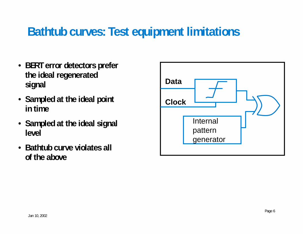
Bathtub curves: Test equipment limitations
• BERT error detectors preferthe ideal regeneratedsignal
• Sampled at the ideal pointin time
• Sampled at the ideal signallevel
• Bathtub curve violates allof the above
Internalpatterngenerator
Data
Clock
Jan 10, 2002Page 7
Transmitter bathtub curves
• A “raw” transmitter signal is being presented to the error detector• Significantly different situation than checking for error on the
output of a receiver/decision circuit• Although the functionality of an error detector is logical in concept, it
is built with high-speed circuitry• RF/analog performance limitations• Depending upon the quality of the design, there can be pattern
dependencies etc that can mask the quality of the signal beingmeasured
• The typical error detector may not be viable for 10 GbEn transmitterbathtubs
Jan 10, 2002Page 8
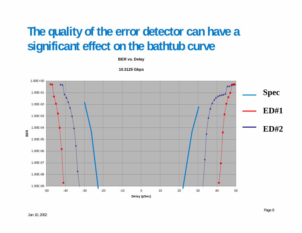
The quality of the error detector can have asignificant effect on the bathtub curve
BER vs. Delay
10.3125 Gbps
1.00E-09
1.00E-08
1.00E-07
1.00E-06
1.00E-05
1.00E-04
1.00E-03
1.00E-02
1.00E-01
1.00E+00
-50 -40 -30 -20 -10 0 10 20 30 40 50
Delay (pSec)
BER
Spec
ED#1
ED#2

Jan 10, 2002Page 9
Jitter can also be characterized using a wide-bandwidth oscilloscope
• Histogram at the eye diagramcrossing point
• Simple, but with limitations• Oscilloscope jitter can mask
true performance• Need to differentiate random
from deterministic• Difficult to assess low
probability events
Jan 10, 2002Page 10
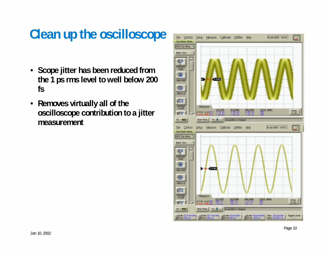
Clean up the oscilloscope
• Scope jitter has been reduced fromthe 1 ps rms level to well below 200fs
• Removes virtually all of theoscilloscope contribution to a jittermeasurement
Jan 10, 2002Page 11
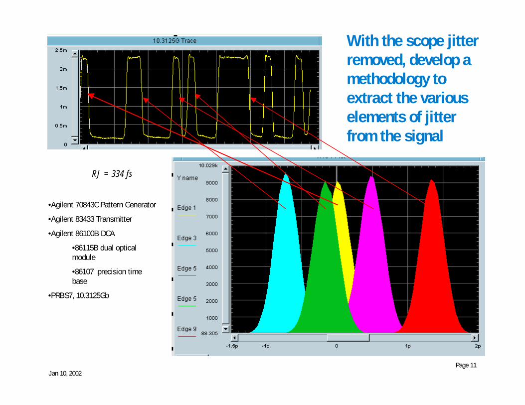
With the scope jitterremoved, develop amethodology toextract the variouselements of jitterfrom the signal
•Agilent 70843C Pattern Generator
•Agilent 83433 Transmitter
•Agilent 86100B DCA
•86115B dual opticalmodule
•86107 precision timebase
•PRBS7, 10.3125Gb
RJ = 334 fs

Jan 10, 2002Page 12
Examine the data edge locations relative to theideal
• Clock signal serves as the idealtime reference
• Long patterns consume time• Techniques being developed to
optimize the analysis for timeefficiency
Jan 10, 2002Page 13
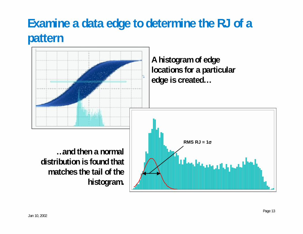
Examine a data edge to determine the RJ of apattern
A histogram of edgelocations for a particularedge is created…
…and then a normaldistribution is found that
matches the tail of thehistogram.
RMS RJ = 1σσσσ
Jan 10, 2002Page 14
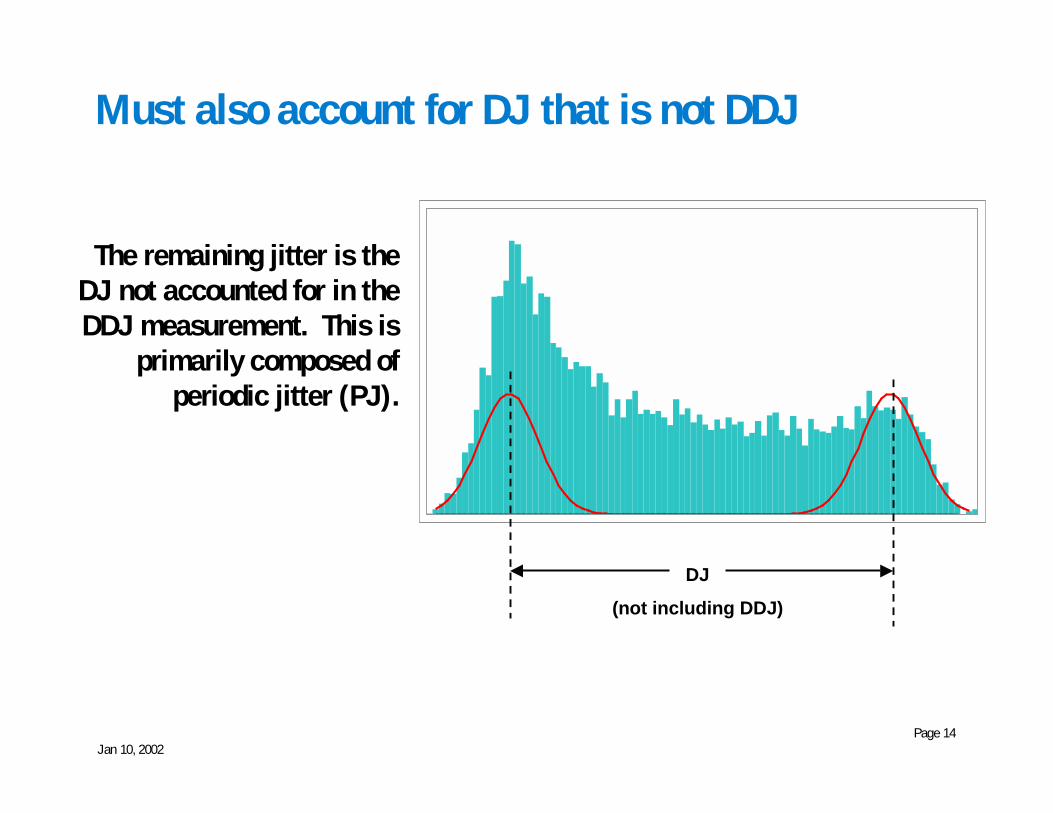
Must also account for DJ that is not DDJ
The remaining jitter is theDJ not accounted for in theDDJ measurement. This is
primarily composed ofperiodic jitter (PJ).
DJ
(not including DDJ)
Jan 10, 2002Page 15
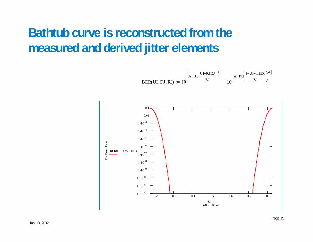
Bathtub curve is reconstructed from themeasured and derived jitter elements
0.2 0.3 0.4 0.5 0.6 0.7 0.81 .10 12
1 .10 11
1 .10 10
1 .10 9
1 .10 8
1 .10 7
1 .10 6
1 .10 5
1 .10 4
1 .10 3
0.01
0.1
Unit Interval
Bit
Erro
r Rat
e
BER UI 0.35, 0.015,( )
UI
BER UI DJ, RJ,( ) 10A B
UI 0.5DJ−RJ
2⋅−
��� 10
A B1 UI− 0.5 DJ⋅−
RJ���
��
2⋅−
���
�
+:=
Jan 10, 2002Page 16
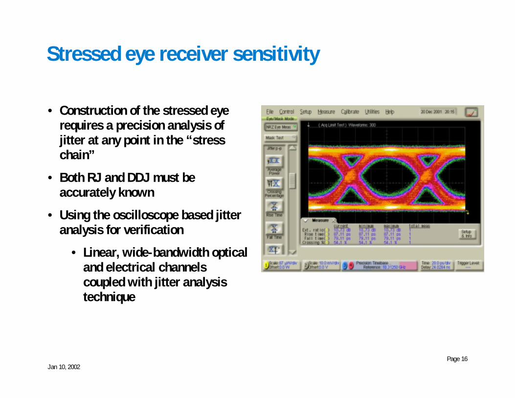
Stressed eye receiver sensitivity
• Construction of the stressed eyerequires a precision analysis ofjitter at any point in the “stresschain”
• Both RJ and DDJ must beaccurately known
• Using the oscilloscope based jitteranalysis for verification
• Linear, wide-bandwidth opticaland electrical channelscoupled with jitter analysistechnique

Jan 10, 2002Page 17
Optical Stressed Eye Generation Setup
whitenoisesource
Agilent 346B
47dBAmp
Agilent 8447F
2^23-1PRBS
Agilent70843C
PG
BiasT
Agilent11612A
-350mv
DCA
trigger
11' coax
LimitAmp
TechcenterLimbert
13Eval brd
-100mV to -600mVModulator
Driver Modulator
1550 nMLasersource
3Ghz 4th orderBessel-Thomson
low-pass filter
OpticalAttenuator
Agilent 8156A
Agilent 83433
clock
86100 with 86107precision timebase
JitterAnalysissoftware
adjust bias to add DCD
Jan 10, 2002Page 18
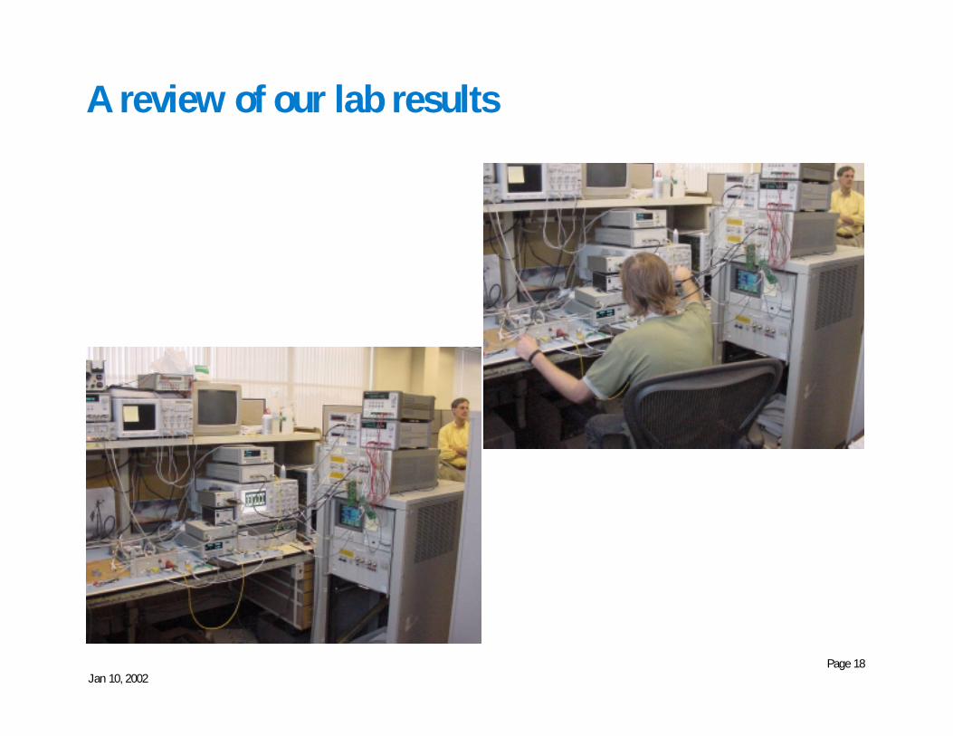
A review of our lab results
Jan 10, 2002Page 19
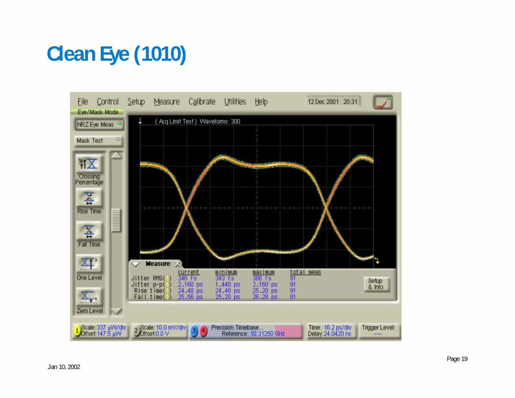
Clean Eye (1010)
Jan 10, 2002Page 20
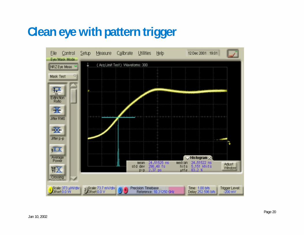
Clean eye with pattern trigger
Jan 10, 2002Page 21
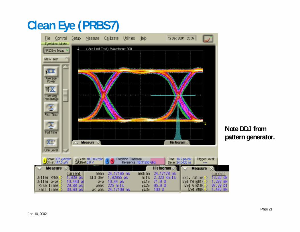
Clean Eye (PRBS7)
Note DDJ frompattern generator.

Jan 10, 2002Page 22
RJ generated by noise source followed by limitamp
Clean Eye:
RJ is adjustable.802.3ae specifiesσσσσ = 1.5ps
Jan 10, 2002Page 23
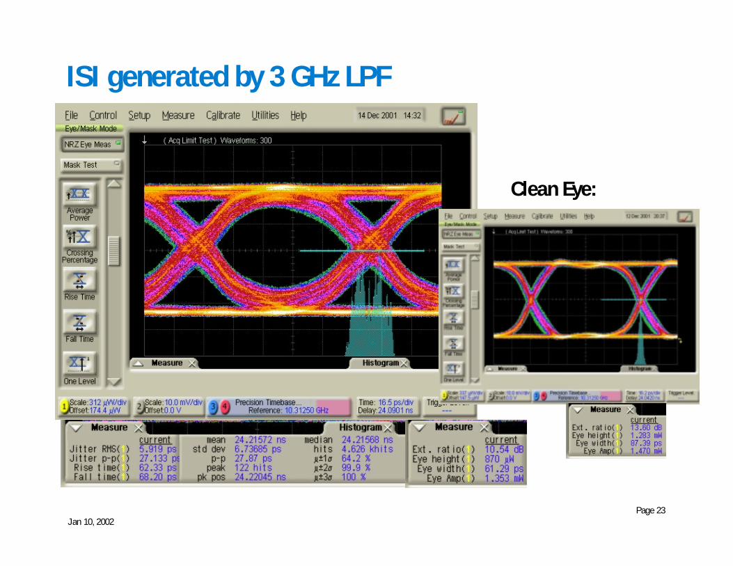
ISI generated by 3 GHz LPF
Clean Eye:
Jan 10, 2002Page 24
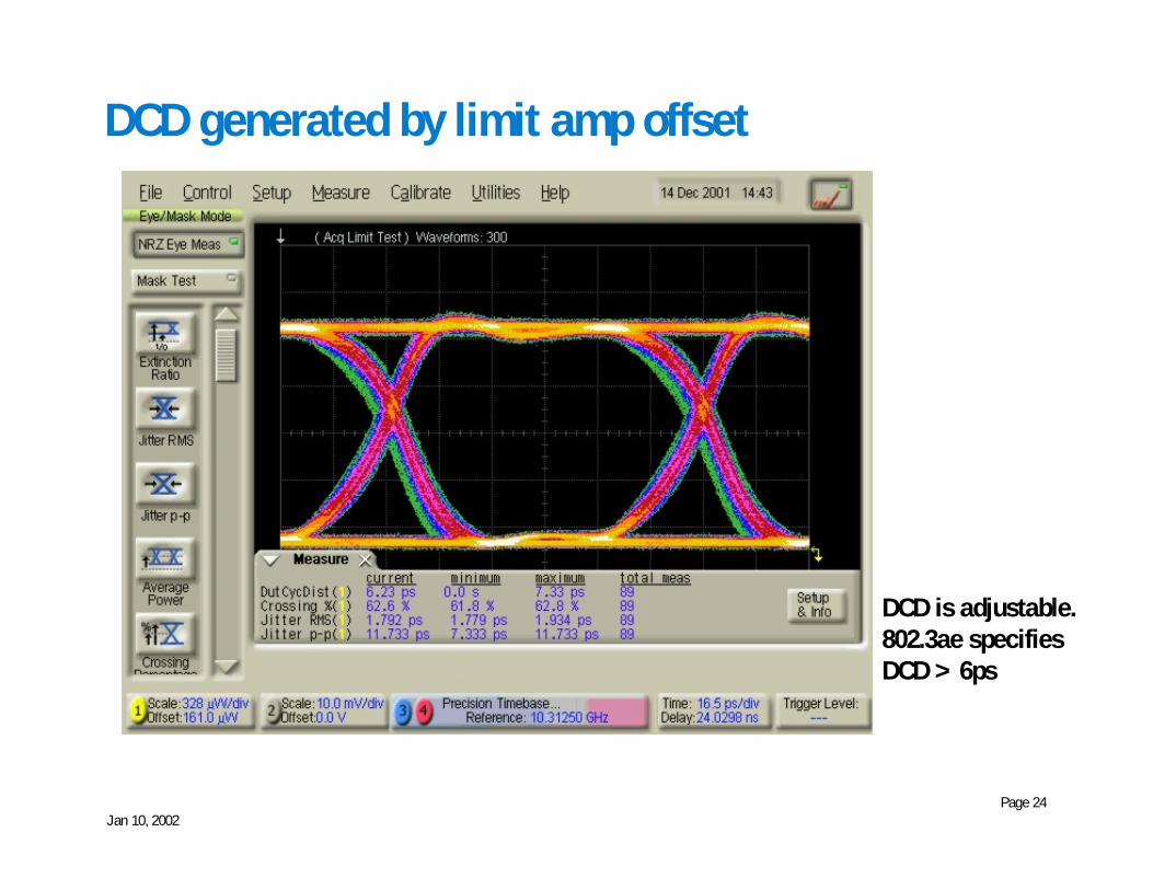
DCD generated by limit amp offset
DCD is adjustable.802.3ae specifiesDCD > 6ps
Jan 10, 2002Page 25
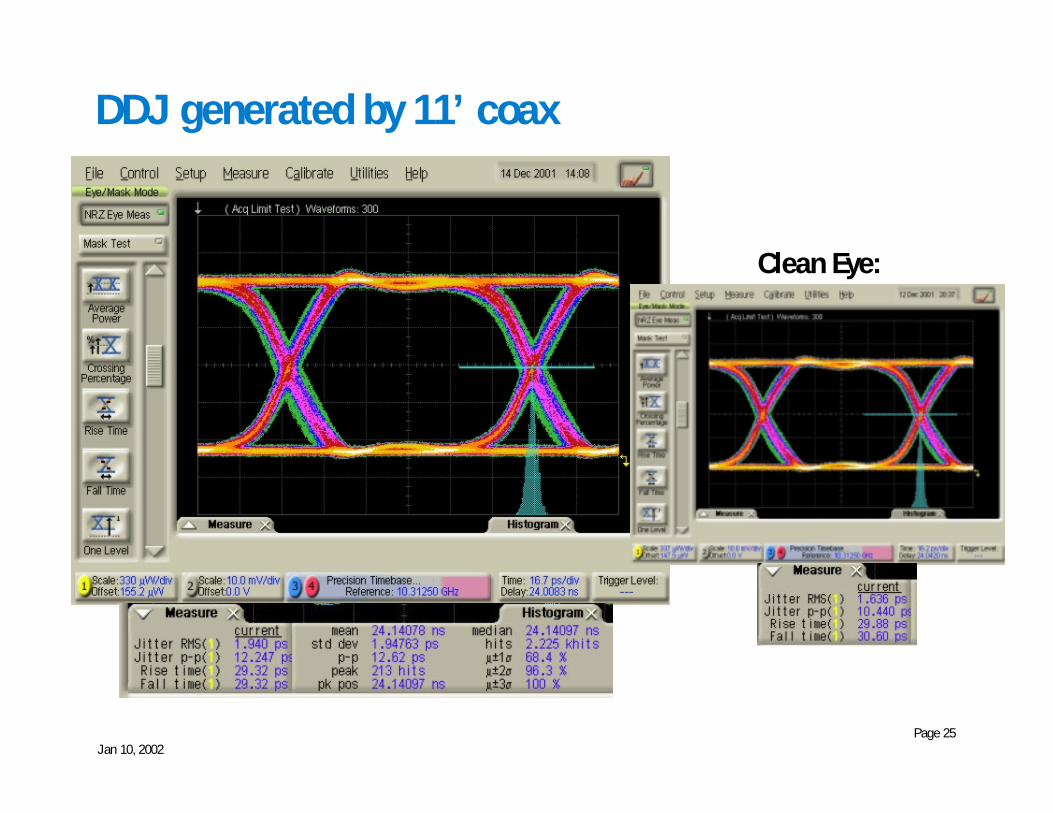
DDJ generated by 11’ coax
Clean Eye:
Jan 10, 2002Page 26
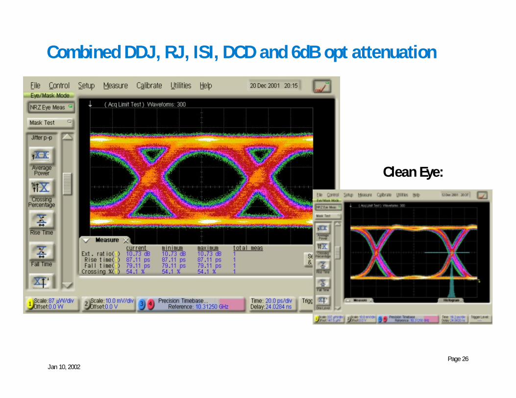
Combined DDJ, RJ, ISI, DCD and 6dB opt attenuation
Clean Eye:
Jan 10, 2002Page 27
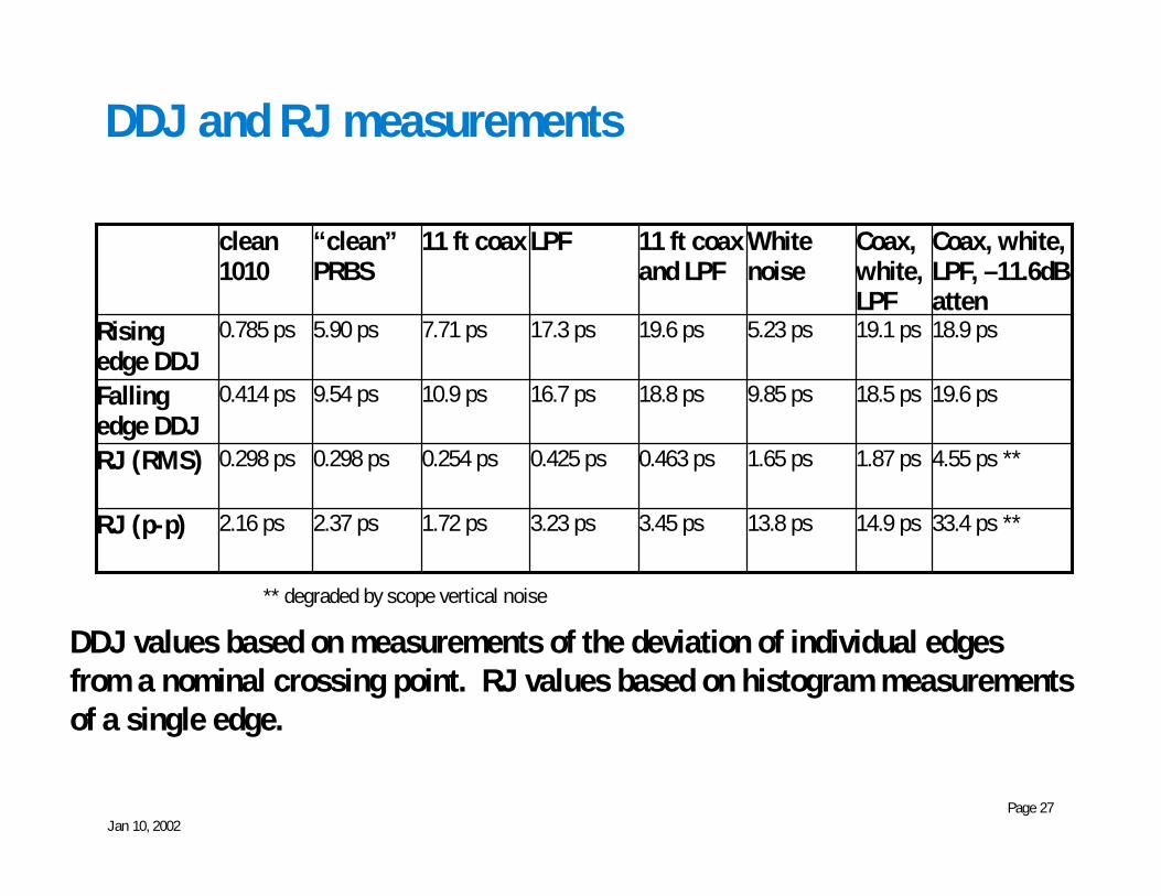
DDJ and RJ measurements
14.9 ps
1.87 ps
18.5 ps
19.1 ps
Coax,white,LPF
4.55 ps **1.65 ps0.463 ps0.425 ps0.254 ps0.298 ps0.298 psRJ (RMS)
19.6 ps9.85 ps18.8 ps16.7 ps10.9 ps9.54 ps0.414 psFallingedge DDJ
3.45 ps
19.6 ps
11 ft coaxand LPF
13.8 ps
5.23 ps
Whitenoise
2.16 ps
0.785 ps
clean1010
1.72 ps
7.71 ps
11 ft coax
3.23 ps
17.3 ps
LPF
18.9 ps5.90 psRisingedge DDJ
33.4 ps **2.37 psRJ (p-p)
Coax, white,LPF, –11.6dBatten
“clean”PRBS
DDJ values based on measurements of the deviation of individual edgesfrom a nominal crossing point. RJ values based on histogram measurementsof a single edge.
** degraded by scope vertical noise
Jan 10, 2002Page 28
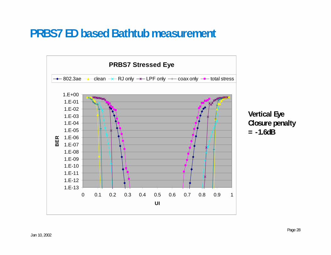
PRBS7 ED based Bathtub measurement
PRBS7 Stressed Eye
1.E-131.E-121.E-111.E-101.E-091.E-081.E-071.E-061.E-051.E-041.E-031.E-021.E-011.E+00
0 0.1 0.2 0.3 0.4 0.5 0.6 0.7 0.8 0.9 1
UI
BER
802.3ae clean RJ only LPF only coax only total stress
Vertical EyeClosure penalty= -1.6dB
Jan 10, 2002Page 29
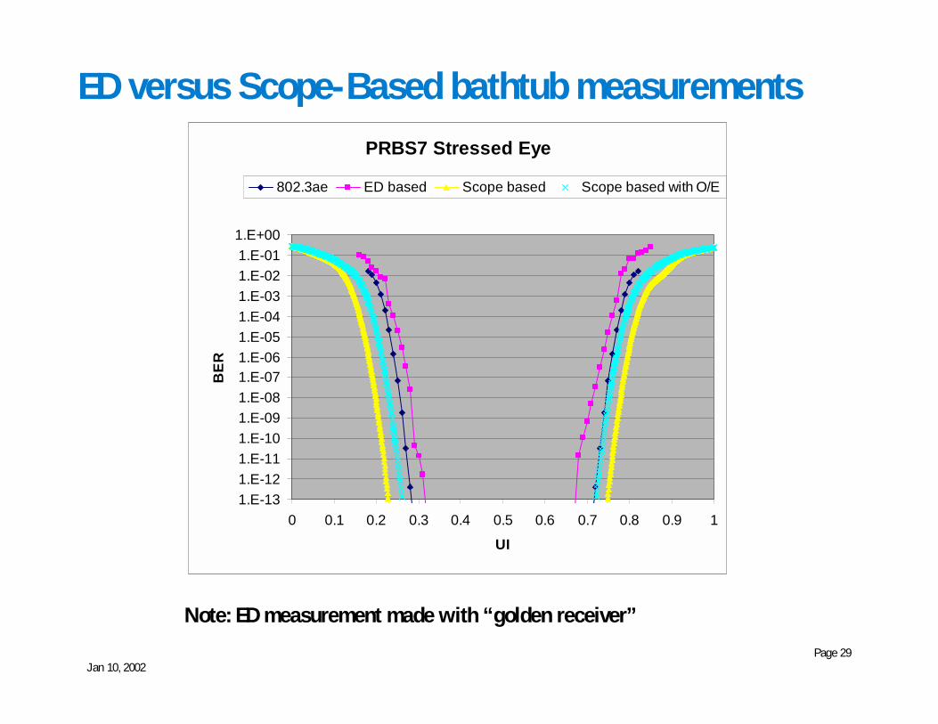
ED versus Scope-Based bathtub measurements
Note: ED measurement made with “golden receiver”
PRBS7 Stressed Eye
1.E-131.E-121.E-111.E-101.E-091.E-081.E-071.E-061.E-051.E-041.E-031.E-021.E-011.E+00
0 0.1 0.2 0.3 0.4 0.5 0.6 0.7 0.8 0.9 1
UI
BER
802.3ae ED based Scope based Scope based with O/E
Jan 10, 2002Page 30
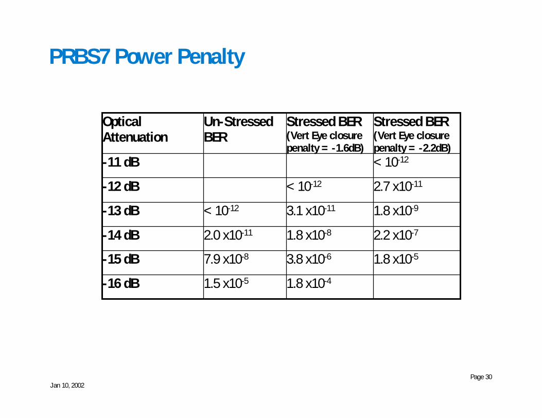
PRBS7 Power Penalty
< 10-12-11 dB
1.8 x10⁻⁴
3.8 x10⁻⁶
1.8 x10⁻⁸
3.1 x10⁻¹¹
< 10-12
Stressed BER(Vert Eye closurepenalty = -1.6dB)
1.8 x10⁻⁵
2.2 x10⁻⁷
1.8 x10⁻⁹
2.7 x10⁻¹¹
Stressed BER(Vert Eye closurepenalty = -2.2dB)
1.5 x10⁻⁵-16 dB7.9 x10-8-15 dB2.0 x10-11-14 dB< 10-12-13 dB
-12 dB
Un-StressedBER
OpticalAttenuation
Jan 10, 2002Page 31
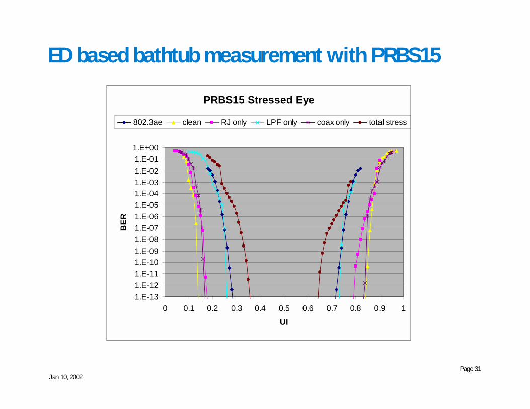
ED based bathtub measurement with PRBS15
PRBS15 Stressed Eye
1.E-131.E-121.E-111.E-101.E-091.E-081.E-071.E-061.E-051.E-041.E-031.E-021.E-011.E+00
0 0.1 0.2 0.3 0.4 0.5 0.6 0.7 0.8 0.9 1
UI
BER
802.3ae clean RJ only LPF only coax only total stress
Jan 10, 2002Page 32
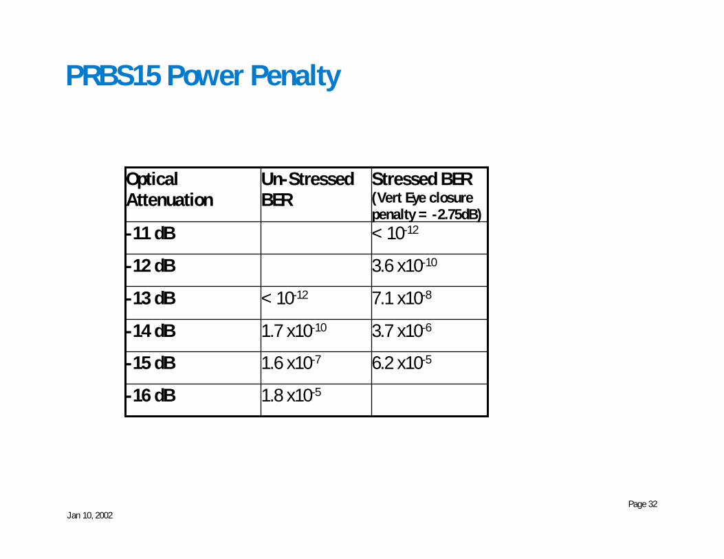
PRBS15 Power Penalty
< 10-12-11 dB
6.2 x10⁻⁵
3.7 x10⁻⁶
7.1 x10⁻⁸
3.6 x10⁻¹⁰
Stressed BER(Vert Eye closurepenalty = -2.75dB)
1.8 x10⁻⁵-16 dB1.6 x10-7-15 dB1.7 x10-10-14 dB< 10-12-13 dB
-12 dB
Un-StressedBER
OpticalAttenuation

Jan 10, 2002Page 33
Some caveats
• We only have access to “instrumentation” grade receivers andtransmitters
• Need to verify bathtub curves on “real” 10 GbEn transmittercomponents
• Need to verify stressed eye performance on “real” 10 GbEn receivercomponents