greensmaster 3300, 3400, 3320, 3420 triflex diagnostic
TRANSCRIPT

TRIFLEX DIAGNOSTIC FAULT CODE QUICK REFERENCE TABLE – Revision B Page 1
GREENSMASTER 3300, 3400, 3320, 3420 TRIFLEX
DIAGNOSTIC FAULT CODE QUICK REFERENCE TABLE
Fault Number
Fault Title Controller Affected
Fault Condition/Circuit Description
Additional Notes Service Actions
11 Reel Speed Potentiometer Bad
Master This fault is reported when the reel speed potentiometer reading is out of range, indicating either an open or short circuit.
1) Test the circuit wiring 2) Replace the potentiometer
12 Line Contactor is Open
S/G This fault is reported when the line contactor fault indicates a fault associated with control of the 48 Vdc contactor. If the 48 Vdc logic and Bus voltage of the starter/generator have more than an 8 Vdc difference when the contactor is engaged, this fault will be reported.
The main contactor exists in the 48 Vdc system to connect the 48 Vdc battery pack with the starter/generator and reel motor controllers. The starter/generator controller determines when the main contactor is engaged.
1) Check the voltage across the coil of the contactor. If the coil is energized by the starter/generator, the voltage should be approximately 48 Vdc.
2) Check the voltage across the contactor. It should be 0 Vdc if the contactor is closed.
3) Manually test the functionality of the contactor using the battery and jumpers.
4) Replace the contactor if tests fail.
13 High Temperature Warning - Cutting
Unit 1
Cutting unit
This fault is reported when the cutting unit controller temperature exceeds 90 °C (195 °F). When the 90 °C threshold is reached, the fault reports and the current being sent to the motor is limited on a linear basis until 100 °C (212 °F) is reached. If either the motor controller or the cutting unit motor reach 100 °C, the cutting unit is shut down. This fault is not produced by a bad sensor.
If the fault continues to occur at relatively low loads, replace the cutting unit electric motor.
1) Let the machine cool. 2) Inspect the cutting unit to ensure
the reel spins freely, without binding.
3) Reduce the reel speed. 4) Reduce the mowing speed. 5) If the fault is intermittent, check
the 48 Vdc ground to the motor.
TRIFLEX DIAGNOSTIC FAULT CODE QUICK REFERENCE TABLE – Revision B Page 2
Fault Number
Fault Title Controller Affected
Fault Condition/Circuit Description
Additional Notes Service Actions
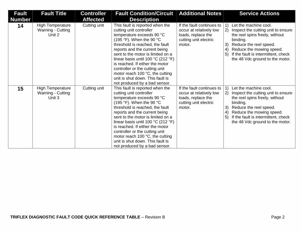
14 High Temperature Warning - Cutting
Unit 2
Cutting unit This fault is reported when the cutting unit controller temperature exceeds 90 °C (195 °F). When the 90 °C threshold is reached, the fault reports and the current being sent to the motor is limited on a linear basis until 100 °C (212 °F) is reached. If either the motor controller or the cutting unit motor reach 100 °C, the cutting unit is shut down. This fault is not produced by a bad sensor.
If the fault continues to occur at relatively low loads, replace the cutting unit electric motor.
1) Let the machine cool. 2) Inspect the cutting unit to ensure
the reel spins freely, without binding.
3) Reduce the reel speed. 4) Reduce the mowing speed. 5) If the fault is intermittent, check
the 48 Vdc ground to the motor.
15 High Temperature Warning - Cutting
Unit 3
Cutting unit This fault is reported when the cutting unit controller temperature exceeds 90 °C (195 °F). When the 90 °C threshold is reached, the fault reports and the current being sent to the motor is limited on a linear basis until 100 °C (212 °F) is reached. If either the motor controller or the cutting unit motor reach 100 °C, the cutting unit is shut down. This fault is not produced by a bad sensor.
If the fault continues to occur at relatively low loads, replace the cutting unit electric motor.
1) Let the machine cool. 2) Inspect the cutting unit to ensure
the reel spins freely, without binding.
3) Reduce the reel speed. 4) Reduce the mowing speed. 5) If the fault is intermittent, check
the 48 Vdc ground to the motor.

TRIFLEX DIAGNOSTIC FAULT CODE QUICK REFERENCE TABLE – Revision B Page 3
Fault Number
Fault Title Controller Affected
Fault Condition/Circuit Description
Additional Notes Service Actions
16 High Temperature Warning –
Starter/Generator
Starter/Generator This fault is reported when the starter/generator controller temperature exceeds the design limit set point. When the overtemp region is entered, motor current is limited on a linear basis until the absolute overtemp value is reached. This fault is not produced by a bad sensor.
Once current becomes limited, the starter/generator motor output power will be limited. This could result to a 48 Vdc system undervoltage warning or fault. In both instances, the Master TEC will cut the PTO and the operator will not be able to mow until the batteries have recovered.
1) Clean the air intake screen of the starter/generator.
2) Reduce the reel speed. 3) Reduce the mowing speed.
17 Motor Speed Stall - CU1
Cutting unit This fault is reported when the cutting unit is active, yet remains at zero rpm for more than three seconds.
Swap motors between cutting units to test the motor. If the fault follows the motor, replace the motor. If the fault stays with the cutting unit, inspect the cutting unit for binding.
1) Check cutting unit 1 for any debris clogging the reel.
2) Check the bedknife adjustment of cutting unit 1.
3) Check to see if the motor can spin without a load.
18 Motor Speed Stall – CU2
Cutting unit This fault is reported when the cutting unit is active, yet remains at zero rpm for more than three seconds.
Swap motors between cutting units to test the motor. If the fault follows the motor, replace the motor. If the fault stays with the cutting unit, inspect the cutting unit for binding.
1) Check cutting unit 2 for any debris clogging the reel.
2) Check the bedknife adjustment of cutting unit 2.
3) Check to see if the motor can spin without a load.
TRIFLEX DIAGNOSTIC FAULT CODE QUICK REFERENCE TABLE – Revision B Page 4
Fault Number
Fault Title Controller Affected
Fault Condition/Circuit Description
Additional Notes Service Actions
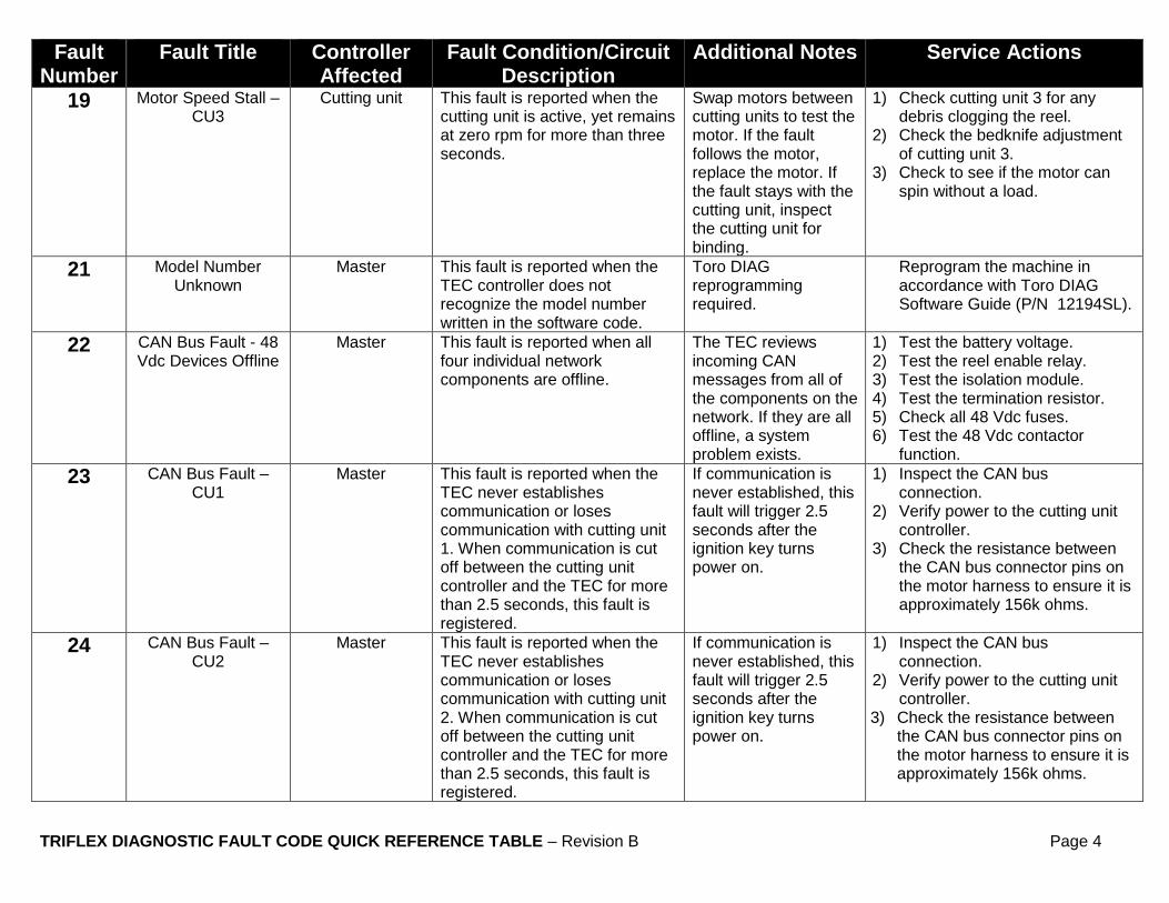
19 Motor Speed Stall – CU3
Cutting unit This fault is reported when the cutting unit is active, yet remains at zero rpm for more than three seconds.
Swap motors between cutting units to test the motor. If the fault follows the motor, replace the motor. If the fault stays with the cutting unit, inspect the cutting unit for binding.
1) Check cutting unit 3 for any debris clogging the reel.
2) Check the bedknife adjustment of cutting unit 3.
3) Check to see if the motor can spin without a load.
21 Model Number Unknown
Master This fault is reported when the TEC controller does not recognize the model number written in the software code.
Toro DIAG reprogramming required.
Reprogram the machine in accordance with Toro DIAG Software Guide (P/N 12194SL).
22 CAN Bus Fault - 48 Vdc Devices Offline
Master This fault is reported when all four individual network components are offline.
The TEC reviews incoming CAN messages from all of the components on the network. If they are all offline, a system problem exists.
1) Test the battery voltage. 2) Test the reel enable relay. 3) Test the isolation module. 4) Test the termination resistor. 5) Check all 48 Vdc fuses. 6) Test the 48 Vdc contactor
function.
23 CAN Bus Fault – CU1
Master This fault is reported when the TEC never establishes communication or loses communication with cutting unit 1. When communication is cut off between the cutting unit controller and the TEC for more than 2.5 seconds, this fault is registered.
If communication is never established, this fault will trigger 2.5 seconds after the ignition key turns power on.
1) Inspect the CAN bus connection.
2) Verify power to the cutting unit controller.
3) Check the resistance between the CAN bus connector pins on the motor harness to ensure it is approximately 156k ohms.
24 CAN Bus Fault – CU2
Master This fault is reported when the TEC never establishes communication or loses communication with cutting unit 2. When communication is cut off between the cutting unit controller and the TEC for more than 2.5 seconds, this fault is registered.
If communication is never established, this fault will trigger 2.5 seconds after the ignition key turns power on.
1) Inspect the CAN bus connection.
2) Verify power to the cutting unit controller.
3) Check the resistance between the CAN bus connector pins on the motor harness to ensure it is approximately 156k ohms.
TRIFLEX DIAGNOSTIC FAULT CODE QUICK REFERENCE TABLE – Revision B Page 5
Fault Number
Fault Title Controller Affected
Fault Condition/Circuit Description
Additional Notes Service Actions
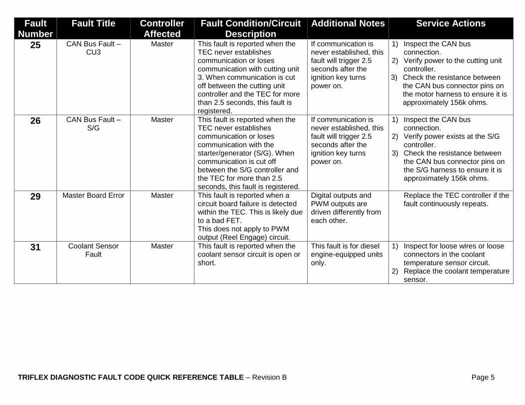
25 CAN Bus Fault – CU3
Master This fault is reported when the TEC never establishes communication or loses communication with cutting unit 3. When communication is cut off between the cutting unit controller and the TEC for more than 2.5 seconds, this fault is registered.
If communication is never established, this fault will trigger 2.5 seconds after the ignition key turns power on.
1) Inspect the CAN bus connection.
2) Verify power to the cutting unit controller.
3) Check the resistance between the CAN bus connector pins on the motor harness to ensure it is approximately 156k ohms.
26 CAN Bus Fault – S/G
Master This fault is reported when the TEC never establishes communication or loses communication with the starter/generator (S/G). When communication is cut off between the S/G controller and the TEC for more than 2.5 seconds, this fault is registered.
If communication is never established, this fault will trigger 2.5 seconds after the ignition key turns power on.
1) Inspect the CAN bus connection.
2) Verify power exists at the S/G controller.
3) Check the resistance between the CAN bus connector pins on the S/G harness to ensure it is approximately 156k ohms.
29 Master Board Error Master This fault is reported when a circuit board failure is detected within the TEC. This is likely due to a bad FET. This does not apply to PWM output (Reel Engage) circuit.
Digital outputs and PWM outputs are driven differently from each other.
Replace the TEC controller if the fault continuously repeats.
31 Coolant Sensor Fault
Master This fault is reported when the coolant sensor circuit is open or short.
This fault is for diesel engine-equipped units only.
1) Inspect for loose wires or loose connectors in the coolant temperature sensor circuit.
2) Replace the coolant temperature sensor.

TRIFLEX DIAGNOSTIC FAULT CODE QUICK REFERENCE TABLE – Revision B Page 6
Fault Number
Fault Title Controller Affected
Fault Condition/Circuit Description
Additional Notes Service Actions
32 Engine Hot - Engine Kill
Master This fault is reported when the TEC sensed the engine temperature to be beyond 115 ºC (240 ºF) for more than 10 seconds.
This fault is for diesel engine-equipped units only. The TEC will shut the engine down to prevent damage.
1) Allow the machine to cool off for 30 minutes.
2) Check the coolant level. 3) Check the cooling fan for proper
function. 4) Inspect the radiator airflow
passageways to ensure they are clear of debris.
5) Test the temperature sender wiring.
6) Test the coolant temperature sender for proper function.
33 48 Vdc Logic (Keyswitch)
Undervolt – CU1
Cutting unit This fault is reported when the 48 Vdc system voltage drops below 32 Vdc at cutting unit 1.
The TEC will shut the cutting units (PTO) down.
1) Check all 48 Vdc fuses. 2) Check the logic power
connection to the cutting unit motor.
3) If more than one device is reporting this fault, check the battery voltage with the engine off.
4) If the battery voltage is ok with engine off, but not when the engine is running, test the S/G for proper generator function.
34 48 Vdc Logic (Keyswitch)
Undervolt – CU2
Cutting unit This fault is reported when the 48 Vdc system voltage drops below 32 Vdc at cutting unit 2.
The TEC will shut the cutting units (PTO) down.
1) Check all 48 Vdc fuses. 2) Check the logic power
connection to the cutting unit motor.
3) If more than one device is reporting this fault, check the battery voltage with the engine off.
4) If the battery voltage is ok with engine off, but not when the engine is running, test the S/G for proper generator function.
TRIFLEX DIAGNOSTIC FAULT CODE QUICK REFERENCE TABLE – Revision B Page 7
Fault Number
Fault Title Controller Affected
Fault Condition/Circuit Description
Additional Notes Service Actions
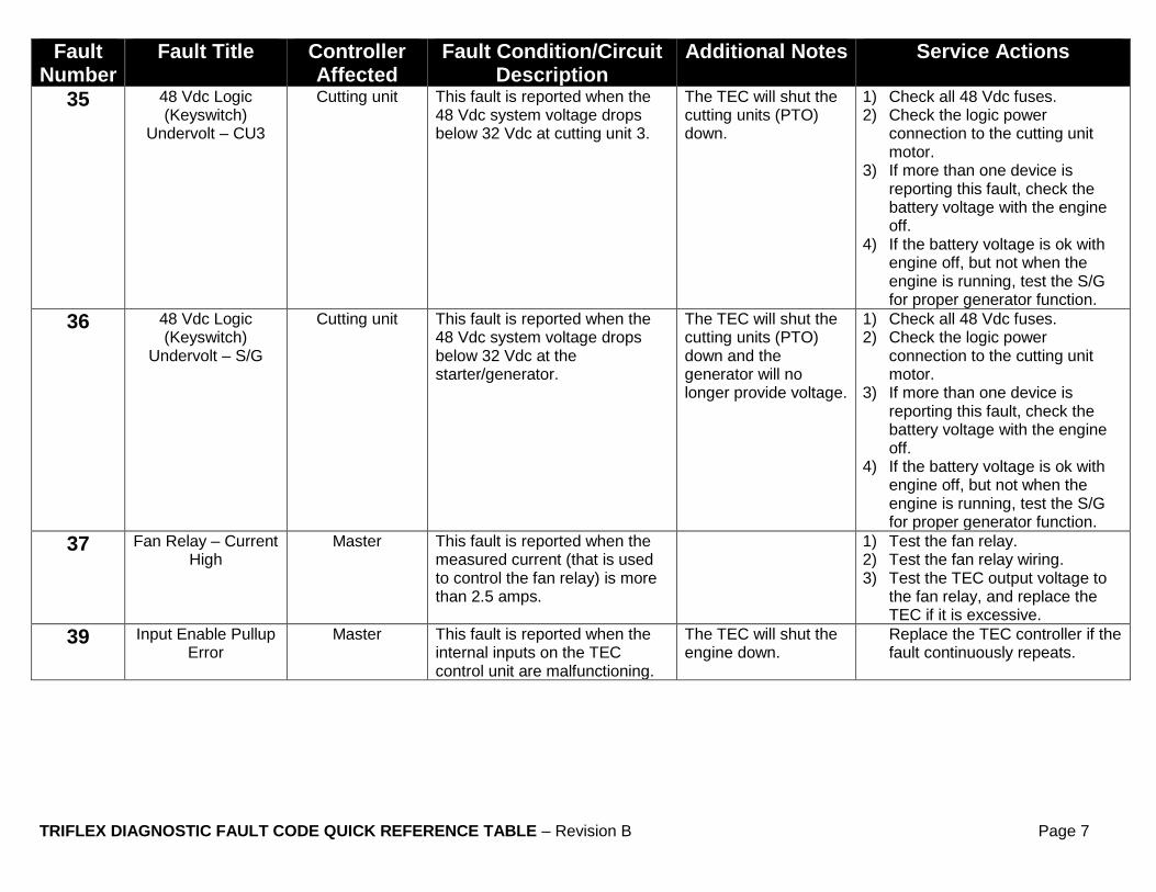
35 48 Vdc Logic (Keyswitch)
Undervolt – CU3
Cutting unit This fault is reported when the 48 Vdc system voltage drops below 32 Vdc at cutting unit 3.
The TEC will shut the cutting units (PTO) down.
1) Check all 48 Vdc fuses. 2) Check the logic power
connection to the cutting unit motor.
3) If more than one device is reporting this fault, check the battery voltage with the engine off.
4) If the battery voltage is ok with engine off, but not when the engine is running, test the S/G for proper generator function.
36 48 Vdc Logic (Keyswitch)
Undervolt – S/G
Cutting unit This fault is reported when the 48 Vdc system voltage drops below 32 Vdc at the starter/generator.
The TEC will shut the cutting units (PTO) down and the generator will no longer provide voltage.
1) Check all 48 Vdc fuses. 2) Check the logic power
connection to the cutting unit motor.
3) If more than one device is reporting this fault, check the battery voltage with the engine off.
4) If the battery voltage is ok with engine off, but not when the engine is running, test the S/G for proper generator function.
37 Fan Relay – Current High
Master This fault is reported when the measured current (that is used to control the fan relay) is more than 2.5 amps.
1) Test the fan relay. 2) Test the fan relay wiring. 3) Test the TEC output voltage to
the fan relay, and replace the TEC if it is excessive.
39 Input Enable Pullup Error
Master This fault is reported when the internal inputs on the TEC control unit are malfunctioning.
The TEC will shut the engine down.
Replace the TEC controller if the fault continuously repeats.
TRIFLEX DIAGNOSTIC FAULT CODE QUICK REFERENCE TABLE – Revision B Page 8
Fault Number
Fault Title Controller Affected
Fault Condition/Circuit Description
Additional Notes Service Actions
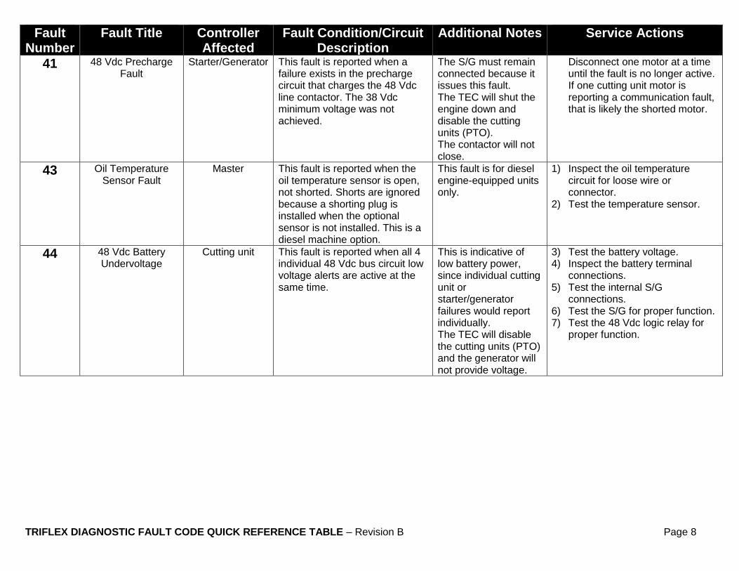
41 48 Vdc Precharge Fault
Starter/Generator This fault is reported when a failure exists in the precharge circuit that charges the 48 Vdc line contactor. The 38 Vdc minimum voltage was not achieved.
The S/G must remain connected because it issues this fault. The TEC will shut the engine down and disable the cutting units (PTO). The contactor will not close.
Disconnect one motor at a time until the fault is no longer active. If one cutting unit motor is reporting a communication fault, that is likely the shorted motor.
43 Oil Temperature Sensor Fault
Master This fault is reported when the oil temperature sensor is open, not shorted. Shorts are ignored because a shorting plug is installed when the optional sensor is not installed. This is a diesel machine option.
This fault is for diesel engine-equipped units only.
1) Inspect the oil temperature circuit for loose wire or connector.
2) Test the temperature sensor.
44 48 Vdc Battery Undervoltage
Cutting unit This fault is reported when all 4 individual 48 Vdc bus circuit low voltage alerts are active at the same time.
This is indicative of low battery power, since individual cutting unit or starter/generator failures would report individually. The TEC will disable the cutting units (PTO) and the generator will not provide voltage.
3) Test the battery voltage. 4) Inspect the battery terminal
connections. 5) Test the internal S/G
connections. 6) Test the S/G for proper function. 7) Test the 48 Vdc logic relay for
proper function.
TRIFLEX DIAGNOSTIC FAULT CODE QUICK REFERENCE TABLE – Revision B Page 9
Fault Number
Fault Title Controller Affected
Fault Condition/Circuit Description
Additional Notes Service Actions
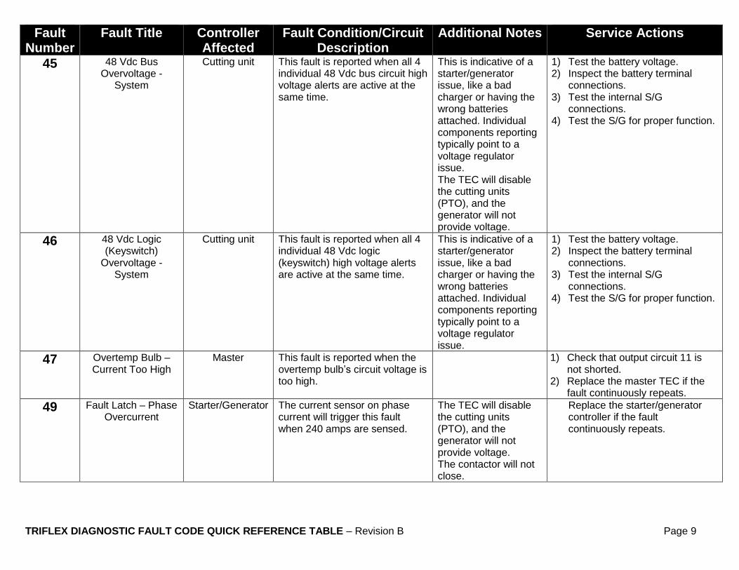
45 48 Vdc Bus Overvoltage -
System
Cutting unit This fault is reported when all 4 individual 48 Vdc bus circuit high voltage alerts are active at the same time.
This is indicative of a starter/generator issue, like a bad charger or having the wrong batteries attached. Individual components reporting typically point to a voltage regulator issue. The TEC will disable the cutting units (PTO), and the generator will not provide voltage.
1) Test the battery voltage. 2) Inspect the battery terminal
connections. 3) Test the internal S/G
connections. 4) Test the S/G for proper function.
46 48 Vdc Logic (Keyswitch)
Overvoltage - System
Cutting unit This fault is reported when all 4 individual 48 Vdc logic (keyswitch) high voltage alerts are active at the same time.
This is indicative of a starter/generator issue, like a bad charger or having the wrong batteries attached. Individual components reporting typically point to a voltage regulator issue.
1) Test the battery voltage. 2) Inspect the battery terminal
connections. 3) Test the internal S/G
connections. 4) Test the S/G for proper function.
47 Overtemp Bulb – Current Too High
Master This fault is reported when the overtemp bulb’s circuit voltage is too high.
1) Check that output circuit 11 is not shorted.
2) Replace the master TEC if the fault continuously repeats.
49 Fault Latch – Phase Overcurrent
Starter/Generator The current sensor on phase current will trigger this fault when 240 amps are sensed.
The TEC will disable the cutting units (PTO), and the generator will not provide voltage. The contactor will not close.
Replace the starter/generator controller if the fault continuously repeats.

TRIFLEX DIAGNOSTIC FAULT CODE QUICK REFERENCE TABLE – Revision B Page 10
Fault Number
Fault Title Controller Affected
Fault Condition/Circuit Description
Additional Notes Service Actions
51 Alternator Master This fault is reported when the alternator generation is faulty. This is determined by the TEC in conjunction with S/G rpm data.
Hydraulic models use indicator lights on the machine to diagnose.
1) Test the alternator function. 2) Inspect the alternator wiring. 3) Test the TEC input.
52 Charging System – Charge Voltage Too
High
Master This fault is reported when the alternator is producing voltage beyond the high limit as determined by the TEC.
1) Check voltage regulator in the 12 Vdc system.
2) Test the alternator function.
57 Preheat Relay/LD Alarm – Current Too
High
Master This fault is reported when the Preheat Relay/LD Alarm current is too high.
This fault is for diesel engine-equipped units only.
1) Ensure the circuit is not shorted. 2) Test the relay for proper
resistance.
59 Line Contactor – Closed Fault
Starter/Generator This is associated with control of the 48 Vdc contactor. The S/G will monitor both sides of the contactor and This fault is reported when the voltages are not supposed to be identical, but they are.
The TEC will disable the cutting units (PTO), and the generator will not provide voltage.
1) Check the voltage across the contactor with the key off. Voltage should be 48 Vdc.
2) Check the voltage across the coil of the contactor with the key OFF. Voltage should be 0 Vdc.
3) Test the functionality of the contactor using the battery and jumpers.
4) Replace the contactor if it fails the test.
63 ID Module Fault Master This fault is reported when the TEC has recognized at least one of the cutting unit electronic addresses is not valid. There is either contention on the bus for the same ID voltage, or an ID module is not functioning.
The master has recognized an issue with the way one or more of the module IDs are functioning.
1) Test the resistance between the ID Pin of the reel motors and 48 Vdc ground. The measurement should be between 17k and 20k ohms.
2) Check for any loose wires. 3) Inspect connectors to ensure
that they are seated fully. 4) Replace the ID module.
64 Main Power Relay Master This fault is reported when the TEC has sensed a main power relay failure and all VBATTs are affected. When only one VBATT is affected, a more likely cause is a bad fuse (see fuse faults in this list).
1) Test the functionality of the main power relay.
2) If the relay passes, ensure the TEC is getting 12 Vdc from the relay.
3) Replace the TEC if everything else checks out and the fault continuously repeats.

TRIFLEX DIAGNOSTIC FAULT CODE QUICK REFERENCE TABLE – Revision B Page 11
Fault Number
Fault Title Controller Affected
Fault Condition/Circuit Description
Additional Notes Service Actions
66 Software Version Incompatibility
Master This fault is reported when one or more of the bus component controllers (cutting unit controllers or the S/G controller) have software that is incompatible with the TEC master controller.
The TEC will disable the engine.
Reprogram the machine using Toro DIAG.
67 S1 Enable - Current Too High
Master This fault is reported when the TEC determines that the S1 coil current is too high.
1) Test the circuit wiring to ensure no short conditions exist.
2) Test the resistance of the solenoid.
3) Replace the TEC if the harness and solenoid tests pass and the fault continuously repeats.
69 Line Contactor - Overcurrent
Starter/Generator The S/G controller monitors the current on both sides of the 48 Vdc contactor. This fault is reported when the contactor’s internal current is too high.
The TEC will disable the cutting units (PTO), and the generator will not provide voltage. The contactor will not close.
1) Test the contactor for proper function
2) Replace the S/G controller if the fault continuously repeats.
71 S2 Lower – Current Too High
Master This fault is reported when the TEC determines that the S2 solenoid coil current is too high.
1) Test the circuit to ensure no short conditions exist.
2) Test the resistance of the S2 solenoid.
74 S3 CU2 and CU3 – Current Too High
Master This fault is reported when the TEC determines that the S3 solenoid coil current is too high.
1) Test the circuit to ensure no short conditions exist.
2) Test the resistance of the S3 solenoid.
76 S4 CU1 – Current Too High
Master This fault is reported when the TEC determines that the S4 solenoid coil current is too high.
1) Test the circuit to ensure no short conditions exist.
2) Test the resistance of the S4 solenoid.
78 SRV Engage Too High
Master This fault is reported when the TEC determines that the SRV solenoid coil current is too high.
1) Test the circuit to ensure no short conditions exist.
2) Test the resistance of the SRV solenoid.

TRIFLEX DIAGNOSTIC FAULT CODE QUICK REFERENCE TABLE – Revision B Page 12
Fault Number
Fault Title Controller Affected
Fault Condition/Circuit Description
Additional Notes Service Actions
81 Start Relay – Current Too High
Master This fault is reported when the current from the TEC to the start relay is too high.
1) Test the circuit to ensure no short conditions exist.
2) Test the resistance of the starter solenoid.
83 Master Contention Fault
Master This fault is reported when the TEC receives a message from another TEC controller on the same bus.
The TEC will disable the engine.
1) Inspect the machine to ensure there are not 2 TEC master controllers on the CAN bus.
2) Reprogram the machine using Toro DIAG.
84 E-reel Enable – Current Too High
Master This fault is reported when the cutting unit enable current exceeds 5 amps.
1) Test the output circuit 12 to ensure no short conditions exist.
2) Test the cutting unit function. 3) If all 3 cutting units function
properly, replace the master TEC.
86 48V Bus Overvolt – CU1
Cutting unit This fault is reported when the 48 Vdc Bus circuit exceeds 67.5 Vdc at cutting unit 1. This fault will cause the TEC to disable the cutting unit motor. Note: This fault can also occur if the generator is faulting and not generating.
All of the machine’s 48 Vdc devices connect to the same 48 Vdc bus. If this is a system issue, the TEC master controller will combine all 4 component 48 Vdc Bus Overvolt faults into a single 48 Vdc Bus Overvolt fault (Fault 45). The TEC will disable the cutting units (PTO). If the lightning bolt in the S/G icon is black, the S/G is generating.
1) If the other 48 Vdc devices are reporting this fault, check the batteries. If the batteries are ok with the engine off, the generator is not generating correctly.
2) Test the generator to see if it is generating correctly.
3) Ensure all S/G motor-to-controller connections are correct and secure.

TRIFLEX DIAGNOSTIC FAULT CODE QUICK REFERENCE TABLE – Revision B Page 13
Fault Number
Fault Title Controller Affected
Fault Condition/Circuit Description
Additional Notes Service Actions
87 48V Bus Overvolt – CU2
Cutting unit This fault is reported when the 48 Vdc Bus circuit exceeds 67.5 Vdc at cutting unit 2. This fault will cause the TEC to disable the cutting unit motor. Note: This fault can also occur if the generator is faulting and not generating.
All of the machine’s 48 Vdc devices connect to the same 48 Vdc bus. If this is a system issue, the TEC master controller will combine all 4 component 48 Vdc Bus Overvolt faults into a single 48 Vdc Bus Overvolt fault (Fault 45). The TEC will disable the cutting units (PTO). If the lightning bolt in the S/G icon is black, the S/G is generating.
1) If the other 48 Vdc devices are reporting this fault, check the batteries. If the batteries are ok with the engine off, the generator is not generating correctly.
2) Test the generator to see if it is generating correctly.
3) Ensure all S/G motor-to-controller connections are correct and secure.
88 48V Bus Overvolt – CU3
Cutting unit This fault is reported when the 48 Vdc Bus circuit exceeds 67.5 Vdc at cutting unit 3. This fault will cause the TEC to disable the cutting unit motor. Note: This fault can also occur if the generator is faulting and not generating.
All of the machine’s 48 Vdc devices connect to the same 48 Vdc bus. If this is a system issue, the TEC master controller will combine all 4 component 48 Vdc Bus Overvolt faults into a single 48 Vdc Bus Overvolt fault (Fault 45). The TEC will disable the cutting units (PTO). If the lightning bolt in the S/G icon is black, the S/G is generating.
1) If the other 48 Vdc devices are reporting this fault, check the batteries. If the batteries are ok with the engine off, the generator is not generating correctly.
2) Test the generator to see if it is generating correctly.
3) Ensure all S/G motor-to-controller connections are correct and secure.

TRIFLEX DIAGNOSTIC FAULT CODE QUICK REFERENCE TABLE – Revision B Page 14
Fault Number
Fault Title Controller Affected
Fault Condition/Circuit Description
Additional Notes Service Actions
89 48V Bus Overvolt – S/G
Starter/Generator This fault is reported when the 48 Vdc Bus circuit exceeds 65 Vdc at the starter/generator. This fault will cause the TEC to disable the starter/generator. Note: This fault can also occur if the generator is faulting and not generating.
All of the machine’s 48 Vdc devices connect to the same 48 Vdc bus. If this is a system issue, the TEC master controller will combine all 4 component 48 Vdc Bus Overvolt faults into a single 48 Vdc Bus Overvolt fault (Fault 45). The TEC will disable the cutting units (PTO), and the generator will not provide voltage. If the lightning bolt in the S/G icon is black, the S/G is generating.
1) If the other 48 Vdc devices are reporting this fault, check the batteries. If the batteries are ok with the engine off, the generator is not generating correctly.
2) Test the generator to see if it is generating correctly.
3) Ensure all S/G motor-to-controller connections are correct and secure.
94 48V Bus Undervolt – CU1
Cutting unit This fault is reported when the 48 Vdc Bus system voltage is below 32 Vdc at cutting unit 1. This fault only reports when the S/G contactor is closed.
All of the machine’s 48 Vdc devices connect to the same 48 Vdc bus. If this is a system issue, the TEC master controller will combine all 4 component 48 Vdc Bus Overvolt faults into a single 48 Vdc Bus undervolt fault (Fault 44). The TEC will disable the cutting units (PTO).
1) Check the 48 Vdc bus fuse. 2) Check the 2-pin 48 Vdc cutting
unit bus connector.
TRIFLEX DIAGNOSTIC FAULT CODE QUICK REFERENCE TABLE – Revision B Page 15
Fault Number
Fault Title Controller Affected
Fault Condition/Circuit Description
Additional Notes Service Actions
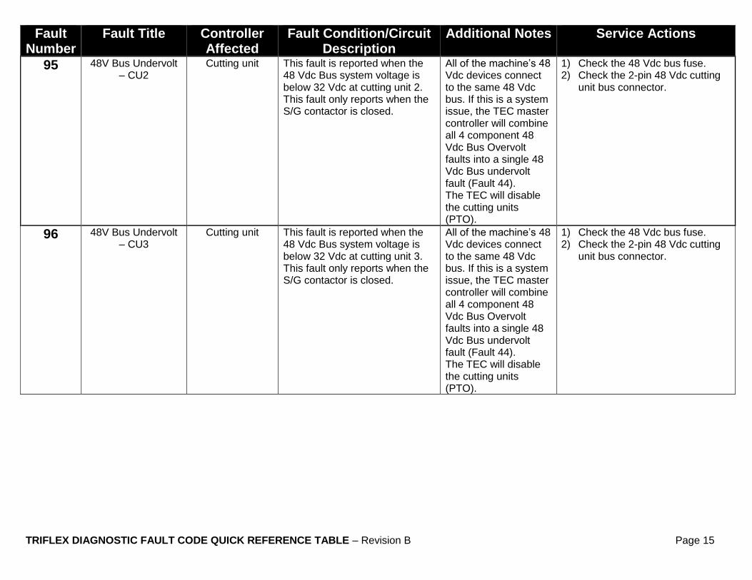
95 48V Bus Undervolt – CU2
Cutting unit This fault is reported when the 48 Vdc Bus system voltage is below 32 Vdc at cutting unit 2. This fault only reports when the S/G contactor is closed.
All of the machine’s 48 Vdc devices connect to the same 48 Vdc bus. If this is a system issue, the TEC master controller will combine all 4 component 48 Vdc Bus Overvolt faults into a single 48 Vdc Bus undervolt fault (Fault 44). The TEC will disable the cutting units (PTO).
1) Check the 48 Vdc bus fuse. 2) Check the 2-pin 48 Vdc cutting
unit bus connector.
96 48V Bus Undervolt – CU3
Cutting unit This fault is reported when the 48 Vdc Bus system voltage is below 32 Vdc at cutting unit 3. This fault only reports when the S/G contactor is closed.
All of the machine’s 48 Vdc devices connect to the same 48 Vdc bus. If this is a system issue, the TEC master controller will combine all 4 component 48 Vdc Bus Overvolt faults into a single 48 Vdc Bus undervolt fault (Fault 44). The TEC will disable the cutting units (PTO).
1) Check the 48 Vdc bus fuse. 2) Check the 2-pin 48 Vdc cutting
unit bus connector.

TRIFLEX DIAGNOSTIC FAULT CODE QUICK REFERENCE TABLE – Revision B Page 16
Fault Number
Fault Title Controller Affected
Fault Condition/Circuit Description
Additional Notes Service Actions
97 48V Bus Undervolt – S/G
Cutting unit This fault is reported when the 48 Vdc Bus system voltage is below 36 Vdc at the starter/generator. This fault only reports when the S/G contactor is closed.
All of the machine’s 48 Vdc devices connect to the same 48 Vdc bus. If this is a system issue, the TEC master controller will combine all 4 component 48 Vdc Bus Overvolt faults into a single 48 Vdc Bus undervolt fault (Fault 44). The TEC will disable the cutting units (PTO), and the generator will not provide voltage.
1) Check to see if a precharge fault exists because the contactor won't engage.
2) Test the contactor for proper function.
3) Inspect the S/G connector.
98 48V Keyswitch Overvolt – CU1
Cutting unit This fault is reported when the 48 Vdc low current logic circuit exceeds 67.5 Vdc at cutting unit 1. This fault will cause the TEC to disable the motor.
If this is a system issue, the TEC master controller will combine all 4 component 48 Vdc Bus Overvolt faults into a single 48 Vdc Bus overvolt fault (Fault 46). The TEC will disable the cutting units (PTO). If the lightning bolt in the S/G icon is black, the S/G is generating.
1) If the other 48 Vdc devices are reporting this fault, check the batteries. If the batteries are ok with the engine off, the generator is not generating correctly.
2) Test the generator to see if it is generating correctly.
3) Ensure all S/G motor-to-controller connections are correct and secure.

TRIFLEX DIAGNOSTIC FAULT CODE QUICK REFERENCE TABLE – Revision B Page 17
Fault Number
Fault Title Controller Affected
Fault Condition/Circuit Description
Additional Notes Service Actions
99 48V Keyswitch Overvolt – CU2
Cutting unit This fault is reported when the 48 Vdc low current logic circuit exceeds 67.5 Vdc at cutting unit 2. This fault will cause the TEC to disable the motor.
If this is a system issue, the TEC master controller will combine all 4 component 48 Vdc Bus Overvolt faults into a single 48 Vdc Bus overvolt fault (Fault 46). The TEC will disable the cutting units (PTO). If the lightning bolt in the S/G icon is black, the S/G is generating.
1) If the other 48 Vdc devices are reporting this fault, check the batteries. If the batteries are ok with the engine off, the generator is not generating correctly.
2) Test the generator to see if it is generating correctly.
3) Ensure all S/G motor-to-controller connections are correct and secure.
101 48V Keyswitch Overvolt – CU3
Cutting unit This fault is reported when the 48 Vdc low current logic circuit exceeds 67.5 Vdc at cutting unit 3. This fault will cause the TEC to disable the motor.
If this is a system issue, the TEC master controller will combine all 4 component 48 Vdc Bus Overvolt faults into a single 48 Vdc Bus overvolt fault (Fault 46). The TEC will disable the cutting units (PTO). If the lightning bolt in the S/G icon is black, the S/G is generating.
1) If the other 48 Vdc devices are reporting this fault, check the batteries. If the batteries are ok with the engine off, the generator is not generating correctly.
2) Test the generator to see if it is generating correctly.
3) Ensure all S/G motor-to-controller connections are correct and secure.

TRIFLEX DIAGNOSTIC FAULT CODE QUICK REFERENCE TABLE – Revision B Page 18
Fault Number
Fault Title Controller Affected
Fault Condition/Circuit Description
Additional Notes Service Actions
102 48V Keyswitch Overvolt – S/G
Starter/Generator This fault is reported when the 48 Vdc low current logic circuit exceeds 65 Vdc at the S/G. This fault will cause the TEC to disable the S/G.
If this is a system issue, the TEC master controller will combine all 4 component 48 Vdc Bus Overvolt faults into a single 48 Vdc Bus overvolt fault (Fault 46). The TEC will disable the cutting units (PTO), and the generator will not provide voltage. If the lightning bolt in the S/G icon is black, the S/G is generating.
1) If the other 48 Vdc devices are reporting this fault, check the batteries. If the batteries are ok with the engine off, the generator is not generating correctly.
2) Test the generator to see if it is generating correctly.
3) Ensure all S/G motor-to-controller connections are correct and secure.
103 Temperature Sensor Fault
Master This fault is reported when the FET temperature sensor and the Motor temperature sensor in the S/G controller have both failed.
The TEC will disable the cutting units (PTO), and the generator will not provide voltage.
Replace the S/G controller if the fault continuously repeats.
104 Over Current Disable – CU1
Cutting unit This fault is reported when the hardware in CU1 detects an overcurrent condition and disables the PWM to stop the motor. This happens when the FET current is measured in excess of a design limit set point.
This can be reported as hardware overcurrent or overvoltage. This fault exists to protect this system in case the SW does not limit the current and voltage correctly. The TEC will disable the cutting units (PTO).
Replace the cutting unit motor.
TRIFLEX DIAGNOSTIC FAULT CODE QUICK REFERENCE TABLE – Revision B Page 19
Fault Number
Fault Title Controller Affected
Fault Condition/Circuit Description
Additional Notes Service Actions
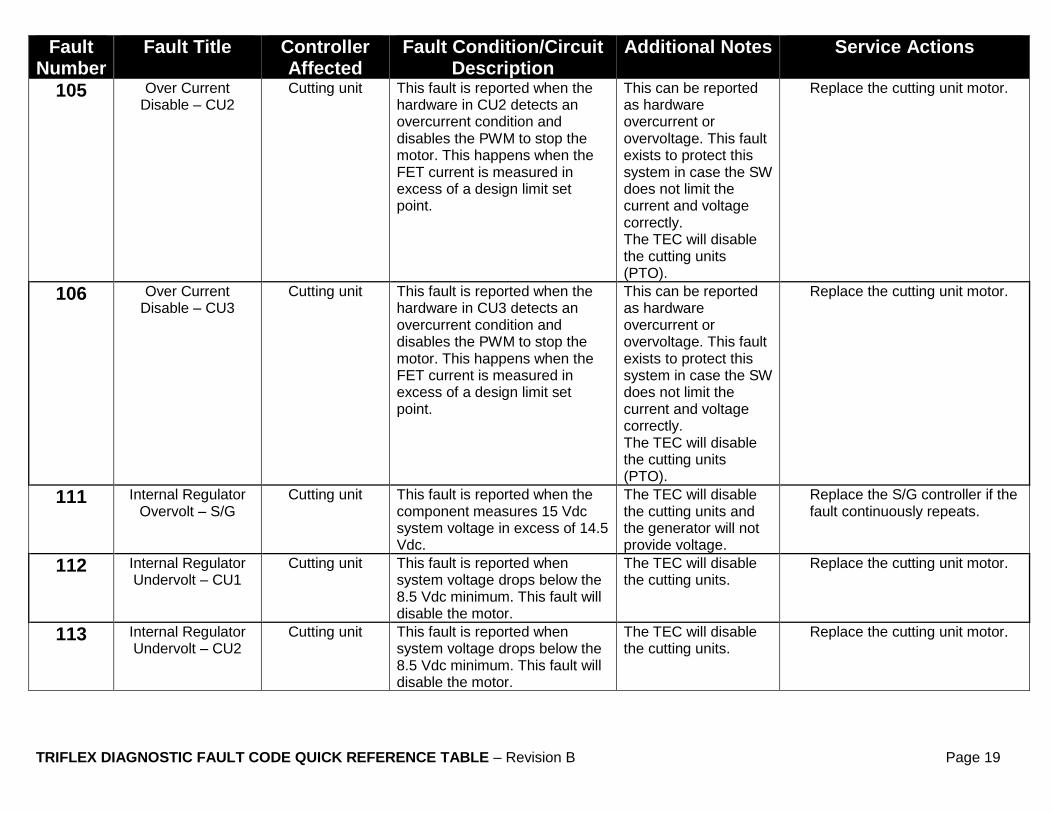
105 Over Current Disable – CU2
Cutting unit This fault is reported when the hardware in CU2 detects an overcurrent condition and disables the PWM to stop the motor. This happens when the FET current is measured in excess of a design limit set point.
This can be reported as hardware overcurrent or overvoltage. This fault exists to protect this system in case the SW does not limit the current and voltage correctly. The TEC will disable the cutting units (PTO).
Replace the cutting unit motor.
106 Over Current Disable – CU3
Cutting unit This fault is reported when the hardware in CU3 detects an overcurrent condition and disables the PWM to stop the motor. This happens when the FET current is measured in excess of a design limit set point.
This can be reported as hardware overcurrent or overvoltage. This fault exists to protect this system in case the SW does not limit the current and voltage correctly. The TEC will disable the cutting units (PTO).
Replace the cutting unit motor.
111 Internal Regulator Overvolt – S/G
Cutting unit This fault is reported when the component measures 15 Vdc system voltage in excess of 14.5 Vdc.
The TEC will disable the cutting units and the generator will not provide voltage.
Replace the S/G controller if the fault continuously repeats.
112 Internal Regulator Undervolt – CU1
Cutting unit This fault is reported when system voltage drops below the 8.5 Vdc minimum. This fault will disable the motor.
The TEC will disable the cutting units.
Replace the cutting unit motor.
113 Internal Regulator Undervolt – CU2
Cutting unit This fault is reported when system voltage drops below the 8.5 Vdc minimum. This fault will disable the motor.
The TEC will disable the cutting units.
Replace the cutting unit motor.

TRIFLEX DIAGNOSTIC FAULT CODE QUICK REFERENCE TABLE – Revision B Page 20
Fault Number
Fault Title Controller Affected
Fault Condition/Circuit Description
Additional Notes Service Actions
114 Internal Regulator Undervolt – CU3
Cutting unit This fault is reported when system voltage drops below the 8.5 Vdc minimum. This fault will disable the motor.
The TEC will disable the cutting units.
Replace the cutting unit motor.
121 Invalid Hall State – CU1
Cutting unit This fault is reported when an invalid hall state is indicated.
This fault does not report until the cutting until motor begins to spin.
Replace the motor on cutting unit 1.
122 Invalid Hall State – CU2
Cutting unit This fault is reported when an invalid hall state is indicated.
This fault does not report until the cutting unit motor begins to spin.
Replace the motor on cutting unit 2.
123 Invalid Hall State – CU3
Cutting unit This fault is reported when an invalid hall state is indicated.
This fault does not report until the cutting unit motor begins to spin.
Replace the motor on cutting unit 3.
124 Invalid Hall State – S/G
Cutting unit This fault is reported when an invalid hall state is indicated.
This fault will not disable the machine’s functionality.
Replace the Starter/Generator motor.
125 Short Detected – CU1
Master This fault is reported when the CU1 controller circuit board has an internal short.
The TEC will stop the engine and open the contactor.
1) Unplug both of the connectors from cutting unit 1 to start the vehicle.
2) Replace the motor on cutting unit 1.
126 Short Detected – CU2
Master This fault is reported when the CU2 controller circuit board has an internal short.
The TEC will stop the engine and open the contactor.
1) Unplug both of the connectors from cutting unit 2 to start the vehicle.
2) Replace the motor on cutting unit 2.
127 Short Detected – CU3
Master This fault is reported when the CU3 controller circuit board has an internal short.
The TEC will stop the engine and open the contactor.
1) Unplug both of the connectors from cutting unit 3 to start the vehicle.
2) Replace the motor on cutting unit 3.
128 Short Detected – CU Unknown
Master This fault is reported when an unidentified circuit board has an internal short. CAN bus network communication still exists with all cutting units.
The TEC will stop the engine and open the contactor.
Unplug both of the connectors from all 3 cutting units to start the vehicle.
TRIFLEX DIAGNOSTIC FAULT CODE QUICK REFERENCE TABLE – Revision B Page 21
Fault Number
Fault Title Controller Affected
Fault Condition/Circuit Description
Additional Notes Service Actions
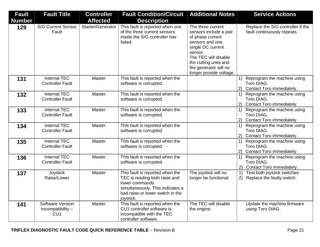
129 S/G Current Sensor Fault
Starter/Generator This fault is reported when one of the three current sensors inside the S/G controller has failed.
The three current sensors include a pair of phase current sensors and one single DC current sensor. The TEC will disable the cutting units and the generator will no longer provide voltage.
Replace the S/G controller if the fault continuously repeats.
131 Internal TEC Controller Fault
Master This fault is reported when the software is corrupted.
1) Reprogram the machine using Toro DIAG.
2) Contact Toro immediately.
132 Internal TEC Controller Fault
Master This fault is reported when the software is corrupted.
1) Reprogram the machine using Toro DIAG.
2) Contact Toro immediately.
133 Internal TEC Controller Fault
Master This fault is reported when the software is corrupted.
1) Reprogram the machine using Toro DIAG.
2) Contact Toro immediately.
134 Internal TEC Controller Fault
Master This fault is reported when the software is corrupted.
1) Reprogram the machine using Toro DIAG.
2) Contact Toro immediately.
135 Internal TEC Controller Fault
Master This fault is reported when the software is corrupted.
1) Reprogram the machine using Toro DIAG.
2) Contact Toro immediately.
136 Internal TEC Controller Fault
Master This fault is reported when the software is corrupted.
1) Reprogram the machine using Toro DIAG.
2) Contact Toro immediately.
137 Joystick Raise/Lower
Master This fault is reported when the TEC is reading both raise and lower commands simultaneously. This indicates a bad raise or lower switch in the joystick.
The joystick will no longer be functional.
1) Test both joystick switches 2) Replace the faulty switch.
141 Software Version Incompatibility –
CU1
Master This fault is reported when the CU1 controller software is incompatible with the TEC controller software.
The TEC will disable the engine.
Update the machine firmware using Toro DIAG.

TRIFLEX DIAGNOSTIC FAULT CODE QUICK REFERENCE TABLE – Revision B Page 22
Fault Number
Fault Title Controller Affected
Fault Condition/Circuit Description
Additional Notes Service Actions
142 Software Version Incompatibility –
CU2
Master This fault is reported when the CU2 controller software is incompatible with the TEC controller software.
The TEC will disable the engine.
Update the machine firmware using Toro DIAG.
143 Software Version Incompatibility –
CU3
Master This fault is reported when the CU3 controller software is incompatible with the TEC controller software.
The TEC will disable the engine.
Update the machine firmware using Toro DIAG.
144 Software Version Incompatibility –
S/G
Master This fault is reported when the S/G controller software is incompatible with the TEC controller software.
The TEC will disable the engine.
Update the machine firmware using Toro DIAG.
145 Software Version Incompatibility –
InfoCenter
Master This fault is reported when the InfoCenter controller software is incompatible with the TEC controller software.
The TEC will disable the engine.
Update the machine firmware using Toro DIAG.
146 CAN Bus Fault – InfoCenter
Master This fault is reported because the TEC never established communication or lost communication with the InfoCenter for 5 seconds.
This fault has occurred when error frames are on the CAN bus.
1) Replace the InfoCenter 2) Unplug the cutting units one by
one until the fault stops reporting.
3) Replace the cutting unit that is identified as causing the fault.
147 Traction Potentiometer Bad
Master This fault is reported when the TEC is reading a traction potentiometer ADC value that is out of range.
The operator can continue mowing without Clip Control by turning it OFF. The fault is only present when Clip Control is ON. When the fault is present, the machine will automatically set the CU reel speed to the 1-9 setting.
1) Check the wiring to the sensor. 2) Ensure the mounting position of
the sensor is correct. 3) Check the sensor wiring to the
TEC controller 4) Replace the sensor.