grand central terminal mep handbook 110510 · grand central terminal new york, ny mechanical,...
TRANSCRIPT

GRAND CENTRAL TERMINAL NEW YORK, NY
MECHANICAL, ELECTRICAL AND PLUMBING TENANT
DESIGN CRITERIA HANDBOOK
December 17, 1996 Rev. 1: July 9, 1998
Rev. 2: Issued October 27, 2009 Rev. 3: Issued May 10, 2011

Page 2
TABLE OF CONTENTS I. GENERAL REQUIREMENTS
II. ENGINEERING DESIGN CRITERIA
A. HVAC B. Electrical C. Plumbing D. Flow Meter Installation Criteria E. Pipe Insulation Criteria F. Sprinkler G. Fire Alarm
III. SUSTAINABLE DESIGN CRITERIA
A. General B. Water Use Reduction C. Energy and Atmosphere D. Indoor Air Quality
IV. SPECIAL DESIGN AND INSTALLATION CRITERIA FOR FOOD SERVICE
TENANTS
A. Kitchen Equipment B. Kitchen Exhaust and Make-Up
1. Restaurant & Café Tenants 2. Lower Concourse Food Retail & Café Tenants 3. All Food Service Tenants
V. SPECIFIC AREA CRITERIA
A. Main Concourse 1. Incoming Concourse/Main Train Room (MC-1A, 1B, 1D, 1E & MC-
2 thru MC-4) 2. Biltmore Room (MC-1) 3. Eddie’s Shoeshine (MC-1C) 4. Small Retail
a. Incoming Concourse (MC-5, MC-6) b. Shuttle Passage (MC-7, MC-15, MC-17) c. Main Concourse (MC-11 thru MC-14, MC-21 thru MC-25) d. 42nd St. Passage (MC-26 thru MC-30). e. Graybar Passage (MC-31 thru MC-39) f. Lexington Passage (MC-60 thru MC-86)

Page 3
g. Vanderbilt Entry (B-60) h. 43rd & Vanderbilt (B-72)
5. Large Retail a. Shuttle Passage (MC-8 thru MC-10) b. 42nd St. Retail (B-54 thru B-59)
6. Ticket W0indows (MC-24) 7. Vanderbilt Room (Waiting Room) 8. Roosevelt Passage (MC-90 thru MC-92)
B. Major Restaurants 1. Balcony Restaurants 2. Campbell Apartment
C. Grand Central Market D. Upper Level 43rd St. Market (416 Lexington Street) E. Lower Concourse
1. Food Retail (LC-1 thru LC-13, LC-23 thru LC-29, LC-33) 2. Cafes (LC-17, LC-19, LC-31, LC-35) 3. Alcoves (LC-42A thru LC-49A) 4. Kiosks (K-1 thru K-7, including storage) 5. Bars (K-8, K-9) 6. Food Court Storage (LCS-1A thru LCS-1N, LCS-11, LCS-12)
F. Tenant Dry Storage
VI. TENANT SUBMISSION FORMS & SCHEDULES
1. Tenant Electrical Data Form 2. Electrical Panelboard Schedule 3. Tenant HVAC Equipment Schedule 4. Tenant Sprinkler Design Basis Form 5. Tenant MEP Review Checklist Form 6. Allowable Pipe Material for Various Systems Pipe Sizes 4”, 125 PSI
Max. Working Pressure 7. Allowable Piping Material for Tenant Steam Systems 8. Allowable Piping Material for Tenant Chilled Water Systems
Page 4
I. GENERAL CRITERIA
(1) All plans, specifications and calculations shall be prepared under the supervision of a Registered Professional Engineer holding a current valid registration in New York in the applicable field of engineering. All mechanical and electrical drawings, with the exception of details and part plans, are to be at the scale as the corresponding architectural drawings.
(2) Complete plans and specifications, with supporting schedules and tabulations, including
complete tenant data on forms provided by the Landlord, shall be submitted to the Landlord for approval in accordance with Landlord’s Tenant Submissions Requirements. At the completion of Tenant’s construction, Tenant shall provide Landlord with reproducible record drawings of the complete installation.
(3) The current editions of the following Codes, Standards, and regulations will govern all
Work performed in Grand Central Terminal:
For Grand Central Terminal, Metro-North follows the current editions of The Uniform Fire Prevention and Building Code of New York State consisting of several subunits, each based on a model code developed by the International Code Council. The following publications are each incorporated by reference into Title 19 of the Official Compilation of Codes, Rules and Regulations of the State of New York (19 NYCRR), and in combination comprise the substantive provisions of the Uniform Code:
• Residential Code of New York State • Building Code of New York State • Existing Building Code of New York State • Plumbing Code of New York State • Mechanical Code of New York State • Fuel Gas Code of New York State • Fire Code of New York State • Property Maintenance Code of New York State • Energy Conservation Construction Code of New York State
Compliance with NFPA 130 is required. For Fire active fire protection systems, sprinkler kitchen exhaust systems and natural gas service, compliance is required with the more restrictive of the codes identified above and the City of New York Mechanical Code. Other Standards and Regulations are referred to only if such other Standards and Regulations are referred to in the codes identified above.
a. ASHRAE Standard 62.1, “Ventilation for Acceptable Indoor Air Quality” b. ASHRAE 90.1, “Energy Standard for Buildings Except Low-Rise Residential
Buildings” c. ASHRAE Standard 55, “Thermal Environmental Conditions for Human
Occupancy” d. Requirements of the Landlord’s insurance carrier
Page 5
Additionally, prepared food service facilities must adhere to the pertinent New York City Department of Health regulations, and fresh food service facilities (i.e. Grand Central Market) must adhere to the New York State Department of Agriculture and Markets regulations. Where conflicts arise among the above, the more stringent shall apply.
(4) Tenant shall provide fire alarm initiation, monitoring and control devices in accordance
with Fire Alarm Criteria below.
(5) Plan review of proposed Tenant designs for Code compliance, including issuance of building permits and compliance inspections, shall be by Metro North Code Review Department. Additionally, food service facilities shall be subject to inspection by the governing Health Department.
(6) Landlord approval of the Tenant’s design is intended to ensure that the Tenant’s design
respects the limitations of the proposed base building systems; to ensure that interfaces between the Tenant’s systems and the base building services can be satisfied; and to ensure that Tenant designs are generally in conformance with good engineering practice. Landlord approval does not ensure satisfactory performance of Tenant systems, nor compliance with any Federal, State or Local codes, regulations, or ordinances. It is the Tenants’ sole responsibility to ensure that Tenant systems meet all regulatory requirements and will perform to the Tenants’ satisfaction.
(7) General reference on Tenant’s drawings to the Tenant MEP Design Criteria or to
“Landlord’s requirements” is not sufficient means of complying with the requirements of this Handbook. It is the responsibility of Tenant’s designers to convey specific applicable criteria to contractors through design drawings and specifications.
(8) Tenant’s engineer shall refer to the lease, Description of Landlord and Tenant Work, and
the Tenant Architectural Design Criteria handbook, for submission requirements and other governing criteria for the design and construction of tenant’s premises. The lease shall govern responsibility.
(9) When Tenant’s premises are remodeled, or when Tenant will occupy a previously
occupied Tenant space, existing construction and equipment within Tenant‘s premises may be reused where beneficial to Tenant. However, reuse of existing construction and equipment does not exempt Tenant from the responsibility to comply with the Design Criteria of Tenant’s lease. Tenant is responsible for surveying existing conditions in Tenant’s premises and reflecting existing conditions in the design. Landlord may require Tenant to make modifications to existing conditions where Landlord finds that existing conditions do not comply with the requirements of Tenant’s lease.
(10) All values and allowances expressed in terms of “per square foot” shall be evaluated
based on Tenant’s leasable square footage within the demised premises.
(11) Tenant’s design shall respect the limitations of the maximum allowable utility service capacities for each utility service as indicated in the Specific Area Criteria. Any tenant

Page 6
requiring additional service capacity beyond the maximum allowable service capacities shall be responsible for all costs associated with providing such additional capacity, including engineering costs.
(12) All dimensions listed in this document for pipe and raceway sizes are intended as
minimums. Tenant should refer to Lease Outline Drawings and/or Base Building drawings for actual design dimensions. Tenant is responsible for any required verification of dimensions in the field prior to completing the design.
(13) Allowable floor loading is 125 psf. Allowable ceiling-supported loading is 10 psf, due to
constraints of the existing structure in many areas of the building. Specific Landlord approval is required for all point loads to be hung from existing ceilings, such as air handlers, transformers, water heaters, heavy light fixtures or piping, etc. (Suspended ceilings may be supported from existing ceilings in most locations.) Coordinate with base building structural engineer prior to issue of design documents.
(14) The design and appearance of all light fixtures and ductwork exposed to public view and
all supports for fixtures, ductwork and piping which are visible to the public (from the shopping areas or from above) are critical to the overall visual effect of the interior design of Grand Central Terminal, and are subject to detailed review and approval by the Landlord. In certain areas, where necessary for consistency in appearance and visual effect, lighting fixtures and other items will be furnished and/or installed by Landlord at Tenant’s expense.
(15) All piping and ductwork to be installed as high as reasonably possible. No holes will be
allowed through structural members without specific Landlord approval.
(16) All tenant work exposed to public view must be painted to match Landlord’s finishes.
(17) Tenant shall restore any materials or finishes (including, but not limited to, fireproofing) damaged by installation of Tenant’s fixtures and equipment, or damaged during the course of Tenant’s construction work.
(18) Tenant shall provide access to all base building MEP system controls located within
Tenant’s premises.
(19) Tenant work in areas outside of Tenant’s Leased Premises, including work over tracks and track platforms below Tenant’s Premises, work in Common Areas, work in Landlord’s mechanical or electrical equipment rooms, and some work over occupied Tenant space below Tenant’s Premises (as directed by the Landlord), shall be performed by the Landlord (or Landlord’s designated contractor) at Tenant expense. Design for such work shall be by Tenant. At tenant’s option, Tenant may furnish equipment or materials for such work, for installation by Landlord.
(20) All work shall be performed in a workmanlike manner and shall be in good usable
condition when completed. Tenant shall require any person performing such work to

Page 7
guarantee the work to be free from defects in workmanship and materials for one (1) year from date of beneficial use or acceptance. Tenant shall also require any such person to be responsible for replacement or repair, without additional charge, of any and all work done or furnished within one (1) year after date of beneficial use or acceptance. The correction of such work shall include, without additional charge, all expenses and damages in connection with such removal, replacement or repair of any part of the work which may be damaged or disturbed thereby. All warranties or guarantees as to materials or workmanship on or with respect to Tenant’s work shall be contained in the Contract or Subcontract which shall be so written that such guarantees or warranties shall inure to the benefit of both Landlord and Tenant, as their respective interests appear, and can be directly enforced by either. Tenant covenants to give Landlord any assignment or assurances necessary to affect the same.
(21) Tenant’s work shall be coordinated with work being performed by the Landlord and other
Tenants in the building, to such extent that the Tenant’s work will not interfere with or delay the completion of any other construction work in the building. Tenant shall provide public liability and property damage insurance for all work performed by Tenant’s Contractors, Subcontractors and/or their suppliers in accordance with the Lease Agreement. Tenant agrees to deliver to the Landlord, within 60 days of substantial completion of Tenant’s construction, a complete release from all liens arising out of the Tenant’s construction work.
(22) For tenant spaces with an area constituting less than 75% of the total building area, sub-
metering equipment shall be installed to measure and record energy uses within the tenant spaces.
(23) For special criteria for each Tenant, refer to Specific Area Criteria.

Page 8
II. ENGINEERING DESIGN CRITERIA
A. HVAC (1) Landlord will provide HVAC capacity for the design conditions below in public
areas, in tenant retail areas, and in merchandise zones only of certain food tenants, when tenant’s lighting and equipment load does not exceed the values stated for each area in the Specific Area Criteria. Landlord provides one of the following configurations of HVAC systems for each Tenant, as indicated in the Specific Area Criteria for each area:
a. Landlord provides a full HVAC system in some areas. (In Grand Central
Market, Tenant shall provide ductwork and diffusers to serve the “back-of-house” areas.)
b. Landlord provides chilled water connections and an outside air duct in or near
Tenant’s space in some areas. Tenant shall provide service valves, fan coil unit, distribution ductwork, diffuser, heating coils, controls, etc., and all related portions of the HVAC system as required for Tenant’s use.
c. Landlord provides ductwork from a central air handling system in some areas,
with a bypass type VAV box in Tenant’s premises and a thermostat temporarily hung at the VAV box. Tenant shall provide branch ductwork and diffusers, and shall install the thermostat as required for Tenant’s use. Tenant shall not obstruct or interfere with return air openings provided by Landlord in Tenant’s demising partitions.
Refer to Air Handling Unit Mounting Detail for illustration of selected criteria.
Capacity will be provided to maintain indoor conditions of 75°F +/-2°F DB, 50% RH on cooling, and 70°F DB on heating, when outdoor conditions are no higher than 92°F DB and 74°F WB, and no lower than 10°F, during operating hours of Grand Central Terminal as defined by Landlord. Building temperature during unoccupied periods may be allowed to drop to 55°F DB during the heating season.
Where Landlord provides entire HVAC system, temperature (measured at the thermostat location) will be maintained within +/-2°F DB of thermostat setting based on the above temperature conditions.
Where heating is required, electric heating coils for the HVAC systems will be installed by each Tenant, except as noted under Specific Area Criteria.
(2) Chilled water shall be used for space conditioning only; chilled water may not be used for refrigeration. Chilled water will not be available on a 24 hour/day basis. Tenants will be supplied chilled water with a pressure differential of at least 20 feet at the point of connection at Tenant’s premises, at an average supply temperature of 46°F
Page 9
(ranging from 40°F to 50°F), to be returned at an average temperature of 56°F (ranging from 50°F to 60°F). Tenant design shall be based on a 10 degree chilled water temperature differential. Chilled water supply will be provided from one hour before Grand Central Terminal opens until the closing time as established by the Landlord, in accordance with the Lease Agreement.
(3) Chilled water piping shall be type L or heavier copper, or Schedule 40 or heavier
galvanized or black steel. Condensate piping shall be copper (type DWV or heavier). Chilled water and condensate piping shall be insulated. Refer to Pipe Insulation criteria below. Tenant shall provide dielectric fittings at all junctions of dissimilar metals in piping systems.
(4) Except where specifically noted otherwise in the Specific Area Criteria, all air
conditioning, heating and ventilating systems and equipment will be furnished and installed by Tenant at Tenant’s expense and subject to Landlord approval. Landlord does not provide any compressed air for Tenant temperature controls. All calculations for the design of Tenant systems shall be in accordance with the latest edition of the ASHRAE Fundamentals Handbook, all applicable codes and requirements, and good engineering practice.
a. Heating Load: Heat loss from the spaces shall be based on maintaining a
minimum of 70°F DB when the temperature outdoors is 10°F DB with a 15 mph wind, with the equipment sized for daytime heating loads.
b. Cooling Load: Cooling load calculations shall be based on maintaining design
indoor conditions when the outdoor conditions do not exceed 92°F DB and 74°F WB, with a 7.5 mph wind. Cooling load calculations shall take into account all interior heat producing items.
c. Cooling load calculations shall include sensible heat gain of 275 Btuh/person
and latent heat gain of 275 Btuh/person, including food, for food service uses; and 250 Btuh/person sensible heat gain and 250 Btuh/person latent, for dry retail.
(5) Tenant shall have the following cooling and heating load calculations prepared by a
registered professional engineer and submitted to Landlord for approval:
a. Block peak load calculations and design airflows for each HVAC system or terminal unit.
b. Calculation of static pressure required from tenant provided air conditioning
equipment. c. Toilet room exhaust air calculation and calculation of static pressure required. d. Exhaust quantities and static pressure calculations for kitchen exhaust.
Page 10
e. Make-up air quantity and static pressure calculations for make-up air.
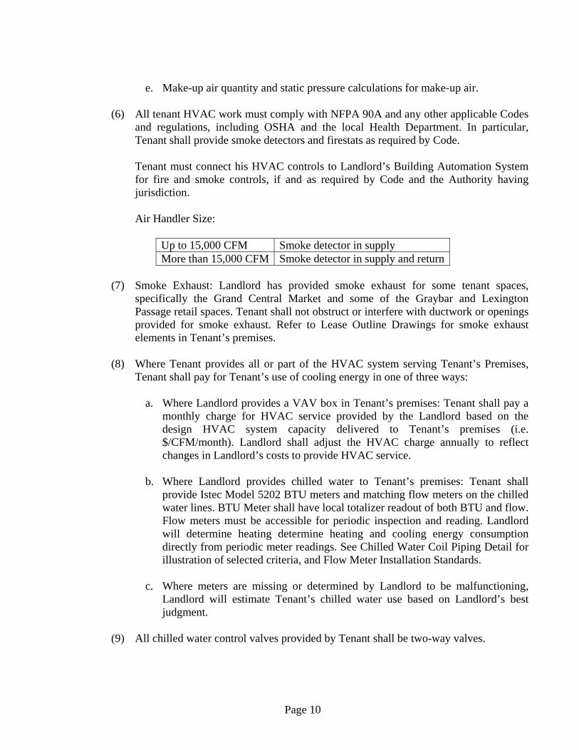
(6) All tenant HVAC work must comply with NFPA 90A and any other applicable Codes
and regulations, including OSHA and the local Health Department. In particular, Tenant shall provide smoke detectors and firestats as required by Code.
Tenant must connect his HVAC controls to Landlord’s Building Automation System for fire and smoke controls, if and as required by Code and the Authority having jurisdiction.
Air Handler Size:
Up to 15,000 CFM Smoke detector in supply More than 15,000 CFM Smoke detector in supply and return
(7) Smoke Exhaust: Landlord has provided smoke exhaust for some tenant spaces,
specifically the Grand Central Market and some of the Graybar and Lexington Passage retail spaces. Tenant shall not obstruct or interfere with ductwork or openings provided for smoke exhaust. Refer to Lease Outline Drawings for smoke exhaust elements in Tenant’s premises.
(8) Where Tenant provides all or part of the HVAC system serving Tenant’s Premises,
Tenant shall pay for Tenant’s use of cooling energy in one of three ways:
a. Where Landlord provides a VAV box in Tenant’s premises: Tenant shall pay a monthly charge for HVAC service provided by the Landlord based on the design HVAC system capacity delivered to Tenant’s premises (i.e. $/CFM/month). Landlord shall adjust the HVAC charge annually to reflect changes in Landlord’s costs to provide HVAC service.
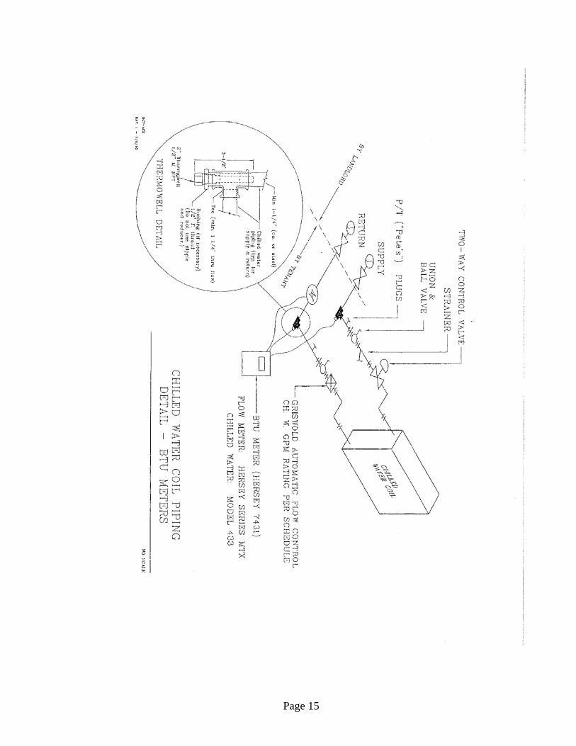
b. Where Landlord provides chilled water to Tenant’s premises: Tenant shall
provide Istec Model 5202 BTU meters and matching flow meters on the chilled water lines. BTU Meter shall have local totalizer readout of both BTU and flow. Flow meters must be accessible for periodic inspection and reading. Landlord will determine heating determine heating and cooling energy consumption directly from periodic meter readings. See Chilled Water Coil Piping Detail for illustration of selected criteria, and Flow Meter Installation Standards.
c. Where meters are missing or determined by Landlord to be malfunctioning,
Landlord will estimate Tenant’s chilled water use based on Landlord’s best judgment.
(9) All chilled water control valves provided by Tenant shall be two-way valves.
Page 11
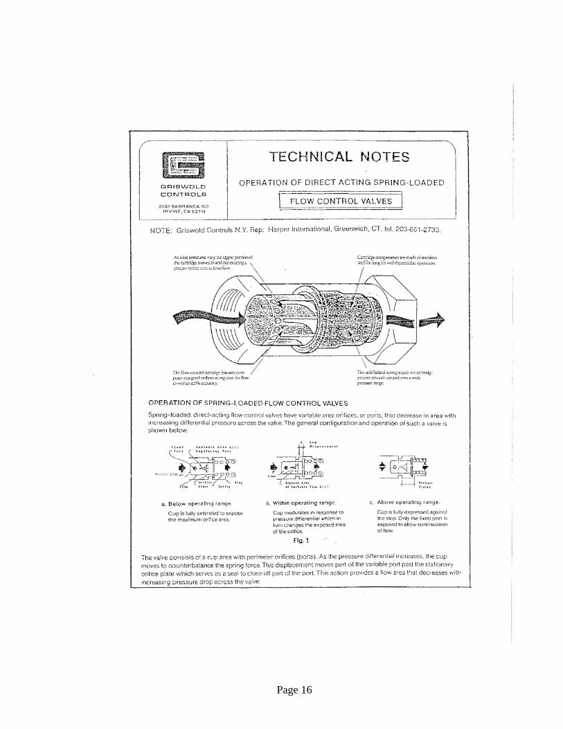
(10) Tenant must provide a non-adjustable automatic flow control valve, similar to Griswold automatic flow control valves (see Flow Control Valve Detail), at each connection to Landlord’s chilled water system. Automatic flow control valve shall be factory set for the lowest standard available flow rate which equals or just exceeds the flow rate specified for each service to that Tenant according to the Specific Area Criteria. Design drawing must give the specific GPM rating for each automatic flow control valve being installed by Tenant.
(11) Steam service will be available to selected tenants, as indicated in the Specific Area
Criteria. Steam supply will be at 5 psig minimum, 15 psig maximum. Tenant shall provide all required steam system elements and controls to meet Tenant’s requirements.
Tenant shall provide steam consumption metering where required in the Specific Area Criteria. Where all steam supplied can be returned as condensate, Tenant shall provide a steam condensate receiver, condensate pump, and meter to measure steam usage, Condensate meter shall be similar to Hersey Series MTX, Model 414, installed on the discharge side of the condensate pump. See Flow Meter Installation Standards below. Where condensate is not recoverable (e.g. steam humidification), Tenant shall provide a steam consumption meter acceptable to the Landlord. Where Tenant’s steam or condensate meter is missing or determined by Landlord to be non-functional, Landlord shall estimate Tenant’s steam use based on Landlord’s best judgment.
(12) Where outside air ductwork is provided to Tenant, Tenant’s air conditioning system
shall provide mechanical outside air ventilation in accordance with the greatest of: (a) Recommendations of the current edition of ASHRAE Standard 62.1; (b) The outside air ventilation quantity required by current Code; and (c) Outside air quantity equal to 120% of the design mechanical exhaust quantity other than kitchen exhaust. Tenant shall connect to outside air duct provided by Landlord. Landlord’s outside air fan provides approximately ¼”wc static pressure in the main outside air duct, and Landlord preheats the outside air to 45°F (except where specifically indicated otherwise in the Specific Area Criteria). Tenant shall provide a pressure-independent airflow control device on the outside air connection, similar to Aldes “Constant Air Regulator” (tel.951-351-3441 or 1-800-225-7749), factory set for the approved outside airflow rate, or a pressure independent constant airflow terminal box set for the approved outside airflow rate.
(13) Noise Criteria
Mechanical and related equipment installed by Tenant must conform to the following noise and vibration limits:
a. When in operation, Tenant’s equipment must not increase the sound level in any
adjacent occupied space (not occupied by the Tenant) to a level higher than NC-
Page 12
40 when measured by an octave-band analyzer sound level meter inside the adjacent space.
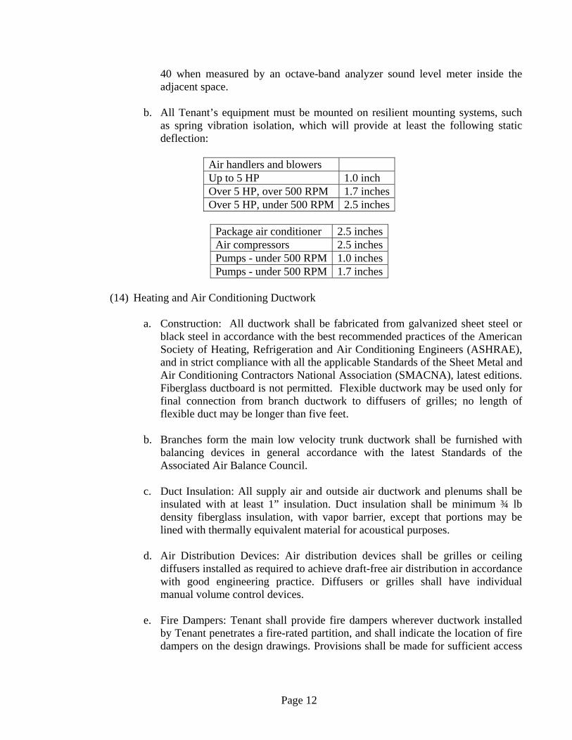
b. All Tenant’s equipment must be mounted on resilient mounting systems, such
as spring vibration isolation, which will provide at least the following static deflection:
Air handlers and blowers Up to 5 HP 1.0 inch Over 5 HP, over 500 RPM 1.7 inchesOver 5 HP, under 500 RPM 2.5 inches
Package air conditioner 2.5 inchesAir compressors 2.5 inchesPumps - under 500 RPM 1.0 inchesPumps - under 500 RPM 1.7 inches
(14) Heating and Air Conditioning Ductwork
a. Construction: All ductwork shall be fabricated from galvanized sheet steel or
black steel in accordance with the best recommended practices of the American Society of Heating, Refrigeration and Air Conditioning Engineers (ASHRAE), and in strict compliance with all the applicable Standards of the Sheet Metal and Air Conditioning Contractors National Association (SMACNA), latest editions. Fiberglass ductboard is not permitted. Flexible ductwork may be used only for final connection from branch ductwork to diffusers of grilles; no length of flexible duct may be longer than five feet.
b. Branches form the main low velocity trunk ductwork shall be furnished with
balancing devices in general accordance with the latest Standards of the Associated Air Balance Council.
c. Duct Insulation: All supply air and outside air ductwork and plenums shall be
insulated with at least 1” insulation. Duct insulation shall be minimum ¾ lb density fiberglass insulation, with vapor barrier, except that portions may be lined with thermally equivalent material for acoustical purposes.
d. Air Distribution Devices: Air distribution devices shall be grilles or ceiling
diffusers installed as required to achieve draft-free air distribution in accordance with good engineering practice. Diffusers or grilles shall have individual manual volume control devices.
e. Fire Dampers: Tenant shall provide fire dampers wherever ductwork installed
by Tenant penetrates a fire-rated partition, and shall indicate the location of fire dampers on the design drawings. Provisions shall be made for sufficient access

Page 13
to each fire damper. All fire dampers must carry evidence of UL approval for the rating required for the wall in which they are installed.
f. Where any ductwork and/or diffusers or outlets are provided by Tenant, Tenant
shall engage the services of an AABC or NEBB certified air balance contractor to adjust and completely balance Tenant’s portion of the system to the design air quantities, and Tenant shall provide to Landlord a copy of the certified air balance report showing design and measured air quantities, static pressures, fan motor RPM and motor current.
(15) Tenant air handling units and/or fan coil units shall be as manufactured by Trane,
Carrier, Magic-Aire, McQuay, or approved equal.

Page 14
Page 15
Page 16
Page 17
B. ELECTRICAL
(1) The design capacity of the tenant’s electrical system shall not exceed the capacity given under the Specific Area Criteria for the applicable area without prior written approval by the Landlord, and shall be based on the design conditions which follow.
(2) Electrical service provided for the tenant will be as defined under Specific Area
Criteria for the Applicable area. Where the electrical service is 480V, Tenant will provide his own dry-type transformer to provide 120/208 volt, three phase, four wire for his own use as required. Where Tenant provides a transformer, Tenant shall provide grounding for the 120/208 volt neutral to a base building cold water pipe or to the building structure.
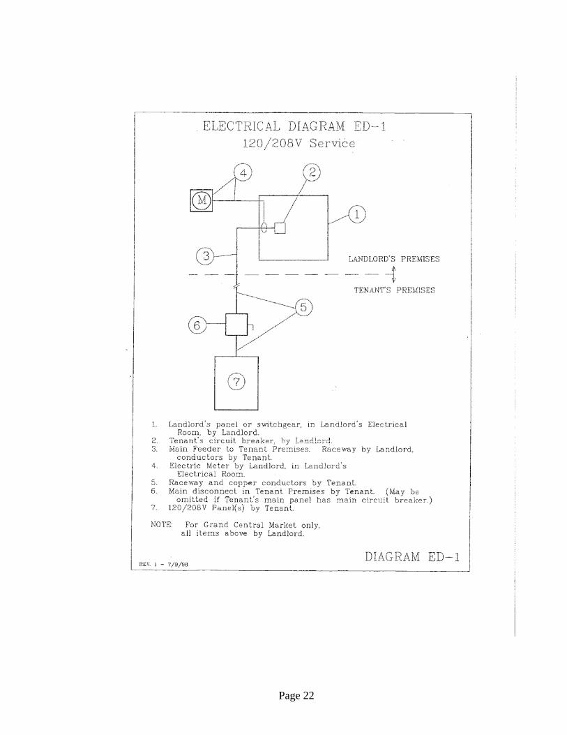
(3) Landlord will make provision for electrical service to Tenant’s premises as indicated
in the Specific Area Criteria for each tenant space. Tenants shall refer to specific Electrical Distribution (ED) diagrams as indicated for each tenant in the Specific Area Criteria. Tenant shall provide a single main disconnect within the space, or other single means of disconnecting all power to the space, such that it will be possible to shut off all power to the space from within the space with a single action.
(4) Landlord shall provide a kilowatt-hour electric meter in Landlord’s electrical room,
installed on Tenant’s main feeder. (5) Landlord provides no emergency power for emergency lighting within Tenant’s
premises. Tenant must provide emergency power and lighting and illuminated exit signs within his Premises if, and as, required by Code. Battery-pack emergency lighting exposed to public view (such as the sales area of Tenant’s space) must be acceptable in appearance. The following emergency light and illuminated exit sign has been approved for installation in locations exposed to public view:
Emergency Light: Lightalarms Series RC (recessed wall/ceiling) Exit Sign: Emergi-Lite X40 Series (edge lit)
Other types of emergency lights exposed to public view must be submitted for specific Landlord review.
(6) Tenant shall provide time clock control for lighting in the Display Zone of the space
in accordance with the lighting criteria of the Tenant Architectural Design Criteria. Time control shall have seven day clock with at least 10 hour battery back-up, and shall be set to light all lighting within the Display Zone of the space during Grand Central Terminal operating hours, as defined by Landlord.
(7) Tenant shall provide a ceiling access panel plus a light and a convenience outlet
(similar to Leviton 9726-C) near all Tenant mechanical equipment located above the ceiling. Wall mounted light switch similar to Leviton 5226 shall be located near the access panel to ceiling space and shall have lighted pilot for ease of location.

Page 18
(8) Tenant’s engineer shall refer to the Tenant Architectural Design Criteria guidelines specified as it pertains to tenant’s space lighting. Complete descriptive information must be submitted to Landlord, including pictorial representation, for approval of all lighting fixtures exposed to public view. Particular care must be taken to select fixtures which will present a neat, finished appearance when viewed from above in any location where the top of the fixtures is exposed to public view.
(9) Materials, products and equipment, including components thereof, shall be new and
be identified by Underwriter Laboratories, Inc. as suitable for the purpose, and shall meet the requirements of the National Electrical Code, of any local Electrical Codes, and of local authorities having jurisdiction. Materials, products and equipment, including components thereof, shall be sized in conformity with the requirements of the National Electrical Code, shall be approved by UL and/or NEMA for the purpose, and shall meet the requirements of other recognized standards, such as ASTM, IEEE, IPCEA, and NFPA, where the requirements of such standards are more stringent than those cited above.
(10) All conductors shall be soft-drawn annealed copper. Aluminum conductors are not
allowed. All wire and cable shall be NEC types XHHW, THHN or THWN, VW-1 rated, 600 volt. Minimum size shall be #12 AWG.
Generally all wires shall be run in conduit, all conduit runs embedded in concrete or through concrete walls shall be rigid galvanized steel. EMT conduit with compression type fittings shall be used elsewhere. Set screw fittings are not permitted.
Branch circuits run concealed in hung ceilings or in stubbed partitions may be run in flexible metal conduit or Type MC cable. NEC Type AC cable (“BX”) is not permitted.
(11) The following color coding shall be used for all Tenant 120/208V wiring:
Phase A Red Phase B BlackPhase C Blue
(12) Tenant’s distribution and lighting panelboards shall be of the three phase, four wire
distributed phasing type, unless otherwise noted, and Tenant’s circuiting shall be arranged to present, as nearly as possible, an evenly balanced load on all phases. All circuit breakers shall be bolt-on. Provide breaker locks on circuits serving emergency lighting and any time clocks.
(13) Switches shall be provided for all lighting. Circuit breakers may be used as a switch
only if the circuit breakers are switching duty (SWD) rated circuit breakers. (14) Motors shall be designed to latest NEMA Standards. Motors rated ½ HP and larger
shall be three phase. Motors rated less than ½ HP may be single phase. Manual motor
Page 19
starters with overload protection may be used for fractional horsepower motors. Three – phase starters shall be provided with overload relay in each phase. Magnetic motor starter shall be used for integral horsepower motors. Combination starters, when used, shall contain fusible switches. Reduced voltage starters shall be used for all motors larger than 100 HP.
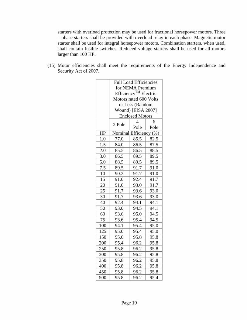
(15) Motor efficiencies shall meet the requirements of the Energy Independence and
Security Act of 2007.
Full Load Efficiencies for NEMA Premium EfficiencyTM Electric
Motors rated 600 Volts or Less (Random
Wound) [EISA 2007] Enclosed Motors
2 Pole 4
Pole 6
Pole HP Nominal Efficiency (%) 1.0 77.0 85.5 82.5 1.5 84.0 86.5 87.5 2.0 85.5 86.5 88.5 3.0 86.5 89.5 89.5 5.0 88.5 89.5 89.5 7.5 89.5 91.7 91.0 10 90.2 91.7 91.0 15 91.0 92.4 91.7 20 91.0 93.0 91.7 25 91.7 93.6 93.0 30 91.7 93.6 93.0 40 92.4 94.1 94.1 50 93.0 94.5 94.1 60 93.6 95.0 94.5 75 93.6 95.4 94.5 100 94.1 95.4 95.0 125 95.0 95.4 95.0 150 95.0 95.8 95.8 200 95.4 96.2 95.8 250 95.8 96.2 95.8 300 95.8 96.2 95.8 350 95.8 96.2 95.8 400 95.8 96.2 95.8 450 95.8 96.2 95.8 500 95.8 96.2 95.4
Page 20
(16) The following equipment shall be identified with engraved plastic nameplates as to
name and/or function: distribution panels, lighting panels, motor starters, push button stations and transformers.
(17) All electrical work shall be installed so as to be readily accessible for operating,
servicing, maintaining, and repairing. Hangers shall include all miscellaneous steel, such as channels, rods, etc., necessary for the installation of the work and shall be fastened of steel, concrete or masonry, but not to piping. (Specific approval is required for any point loads attached to the ceiling.) Hangers and support systems are an integral part of the visual environment, and all hangers and supports exposed to public view, from surrounding areas, or from above, must be shown in detail on plans submitted to Landlord for review, and are subject to Landlord’s approval for appearance. All hangers must be uniformly spaced and neatly installed, with no excess material beyond what is required for the support function. Select accessories and hardware for a smooth, neat finished appearance. All conduits shall be concealed where possible. Exposed conduit shall be in straight lines parallel with, or at right angles to, column lines or beams and separated by at least 3 inches from water lines whenever they run alongside or across such lines. Conductors shall be in conduit, ducts or approved raceways. All exposed conduit and associated supports installed by Tenant must be painted by Tenant to match Landlord finish.
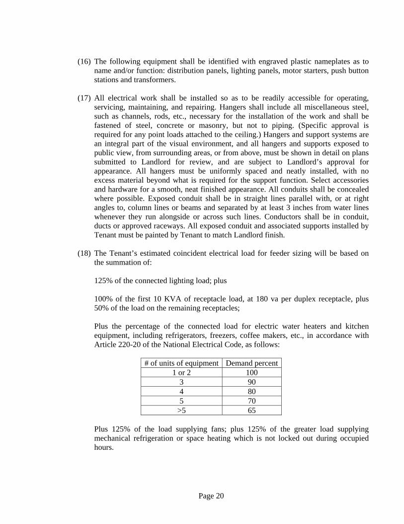
(18) The Tenant’s estimated coincident electrical load for feeder sizing will be based on
the summation of: 125% of the connected lighting load; plus
100% of the first 10 KVA of receptacle load, at 180 va per duplex receptacle, plus 50% of the load on the remaining receptacles;
Plus the percentage of the connected load for electric water heaters and kitchen equipment, including refrigerators, freezers, coffee makers, etc., in accordance with Article 220-20 of the National Electrical Code, as follows:
# of units of equipment Demand percent
1 or 2 100 3 90 4 80 5 70
>5 65 Plus 125% of the load supplying fans; plus 125% of the greater load supplying mechanical refrigeration or space heating which is not locked out during occupied hours.

Page 21
Equipment connected loads shall be based on nameplate volt-amperes (va). Lighting loads shall be computed based on lamp wattage for incandescent loads. For fluorescent and HID loads, use rated lamp wattage plus ballast loss, and add a 10% power factor correction rounded off to the nearest 25 va.
Tenant shall refer to Tenant Electrical Data form for feeder load calculations. Tenant’s calculated feeder load shall not exceed the allowable demand load specified in the lease and the Specific Area Criteria.
(19) Tenant shall perform all electrical work and shall submit all calculations in
accordance with the National Electrical Code and all other authorities having jurisdiction, and in accordance with good engineering practice. All calculations shall conform to the appropriate articles in the National Electrical Code. Calculations shall include all branch circuits and feeder (service) tabulation. All calculations shall be expressed in volt-amperes (va) or kilovolt-amperes (KVA).
(20) Tenant shall submit complete plans and specifications for Landlord’s approval for all
electrical work, including lighting and power plans, light fixture schedule, and one-line riser diagrams. Tenant shall also submit completed Tenant Electrical Data Form and Electrical Panel Board Schedules in the format provided by the Landlord. The tenant shall obtain Landlord’s written approval before any work is started.
(21) Except where otherwise indicated, Landlord will provide, at Tenant’s expense, an
empty raceway from Telephone Company service point to a point in or adjacent to Tenant’s premises for Tenant’s telephone service. Tenant shall install telephone cabling from the telephone connection into the Tenant’s space, as needed. Tenant must arrange for telephone service directly with the Telephone Company.
(22) Landlord will provide an empty raceway from Landlord’s cable television service
point to a point in or adjacent to Tenant’s premises for cable television service to Restaurant tenants. Cable television service may be made available to other tenants, at Tenant expense, subject to special arrangement with the Landlord.
(23) No equipment or devices, including, but not limited to, light fixtures, signs, antennas,
etc., shall be affixed to the exterior walls or roof of Landlord’s building without Landlord’s specific written approval. Requests for such permission must be accompanied by detailed drawings showing specific details of methods of attachment and waterproofing, as well as line of sight drawings showing visibility from public areas.
(24) Tenant will provide, at his own expense, waterproofed sleeves as shown in the Detail
of Interior Waterproof Sleeve Penetration for any Tenant raceway which passes through floor slabs.
Page 22

Page 23
Page 24
C. PLUMBING
(1) Water, sewer and vent connections will be provided by Landlord in the sizes indicated
under the Specific Area Criteria for each Restaurant or Café space and located in the area shown on the Lease Outline Drawing for each Restaurant or Café space. Sewer connections will be located below the floor slab in the ceiling plenum of the tenant below. Vent connections will be located above the ceiling level of Tenant’s Premises.
(2) Landlord’s domestic water system is designed to provide minimum static pressure of
60 psig at the floor level of the Main Concourse. Any tenant requiring additional water pressure shall provide a local booster pump.
(3) All tenants using domestic water must furnish and install domestic water check meters
similar to Hersey MTX (Model 433 for cold water). See Flow Meter Installation Standards. Where Tenant’s domestic water meters are missing or determined by Landlord to be non-operational, Landlord shall estimate Tenant’s water consumption based on Landlord’s best judgment.
(4) Tenant will provide waterproofed sleeves as shown in the Detail of Interior
Waterproof Sleeve Penetration for Tenant piping which passes through floor slabs. (5) Floor slabs in kitchens and food preparation areas will be waterproofed by Tenant at
Tenant’s expense, prior to installation of Tenant’s flooring or equipment. Floor drains shall have flashing collars and/or flange collars provided by Tenant to receive fluid applied waterproofing membrane (similar to Laticrete) applied by Tenant to maintain area waterproofing. Floors must slope to floor drains.
(6) Location of all openings through floor slabs and waste piping in the ceiling space of
the tenant space below to be approved in writing prior to coring and completed by Landlord at Tenant’s expense. No openings can be located through a post-tensioned beam or post-tensioned slab.
(7) All waste piping designed and installed for the drainage of kitchen equipment
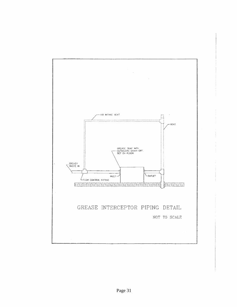
(specifically including the waste lines from pot sinks, scullery sinks, dishwasher scraper tables, water-wash kitchen hoods, wok ranges, and other fixtures as determined by the local Plumbing Inspector or Landlord) shall discharge through a grease interceptor prior to their connection to Landlord’s sanitary system. Garbage disposers shall discharge through a solids interceptor before connection to a grease trap. Dishwasher hot water sanitizing (180°F) rinse shall not discharge through a grease interceptor (see Grease Interceptor Piping Detail). Floor drains shall not be permitted near fixtures requiring discharge to a grease interceptor.
All grease interceptors shall have automatic grease draw-off feature (e.g. Zurn Ejecto-Matic or Smith Series 8000GT), and must be installed above the floor. Grease

Page 25
interceptors installed through the floor slab will not be permitted. Grease interceptors shall be readily accessible for cleaning.
(8) Each tenant requiring domestic hot water shall furnish and install an electric hot water
heater as required to meet tenant’s hot water needs. Restaurant tenants may provide steam water heaters where steam is available. Water heater shall be fully insulated and steel jacketed. Instantaneous water heaters or water heaters with less than 1.5 gallons of tank capacity may not be used.
Water heaters may not be set directly on the floor in food service areas, in order to avoid creating an area of the floor which cannot be adequately cleaned. Water heaters may be mounted on metal stands or on brackets supported from the walls at least 10” above the floor (with appropriate structural support), or on top of walk-in coolers where space is available. Coordinate with base building structural engineer prior to issue of design documents.
(9) All tenants must provide rest rooms for their customers and staff if and as required by
Code and the Authority Having Jurisdiction. (10) Plumbing fixtures provided by Tenant must be new, of first quality, and designed for
the purpose, manufactured by American Standard Company, Kohler, Eljer, or similar. All fixtures must be supported from the floor, directly or by means of floor-mounted supports.
(11) Natural gas piping shall be installed in accordance with requirements of the National
Fuel Gas Code (NFPA 54), and shall be approved in writing by the Landlord. Gas service will be available for cooking purposes and for direct-fired makeup air heat only, and only where so indicated under Specific Area Criteria, and in the quantities indicated under Specific Area Criteria. Tenant must obtain Landlord’s specific approval of any gas installation before the Tenant’s main gas service valve may be opened.
(12) Tenant shall provide for future installation of a natural gas meter in Tenant’s premises
as follows: Tenant’s design plans shall identify a location for the future gas meter; the gas meter must be located below the suspended ceiling within Tenant’s premises, in a dry location not subject to damage or abuse. Tenant’s main gas service line must pass directly above the future meter location, upstream of any connections to Tenant’s gas-fired equipment. At the future meter location in the main gas line, Tenant shall provide a length of straight pipe 15” to 20” long, with unions at both ends, to facilitate future installation of the gas meter.
(13) Tenant’s use of natural gas shall be estimated or measured by one of the following
methods:
a. Each Tenant using natural gas will pay a portion of Landlord’s gas bill based on Tenant’s proportionate share of the total connected gas load on the Landlord’s

Page 26
metered gas service. Landlord shall determine Tenant’s connected gas load based on information from Tenant’s design drawings or based on a survey of Tenant’s gas-fired equipment. Sub-metered gas usage will be excluded from this procedure.
b. If directed by the Landlord, whether during Tenant’s initial construction or at
any subsequent time, Tenant shall install an approved gas sub-meter in the “future” gas meter location described above. Upon installation of the sub-meter, Tenant will be charged for natural gas usage based on the metered usage, using the local gas utility’s rate tariff then in effect. Tenant’s gas meter must be sized for Tenant’s full connected gas load at a pressure loss no greater than 1½” wc.
(14) All piping systems must be compatible with the type of materials used by Landlord,
and shall comply with the following requirements:
a. Drainage, vent pipe and fittings: Service weight hubless cast iron pipe and fittings. Joints: rubber sealing sleeve and stainless steel coupling with stainless steel clamps and bolts as manufactured by Tyler Pipe or equal. Pipe and joining coupling to be from same manufacturer. PVC piping will not be permitted.
b. Water piping above grade: Type L copper tubing, seamless drawn, hard temper
with plain ends ASTM B-88. Fittings: wrought copper with socket ends for 95/5 solder.
c. Gas piping: Black steel pipe schedule 40, ASTM A-53 with threaded ends and
malleable iron threaded fittings, except that gas piping 4” and larger will be welded.
Tenant shall provide dielectric fittings at all connections between dissimilar metals in piping systems.
(15) All valves for domestic water to be 125 test all bronze wedge gate valves or line size
quarter-turn ball valves. Valves for gas piping systems shall be all bronze lubricated plug valve, threaded for screwed pipe.
(16) Pipe to be supported securely from hangers as follows:
a. “Direct Tension” type hangers shall not be used in cinder filled slabs. Specific Landlord approval must be obtained for all point loads attached to the ceiling.
b. Pipe hangers to be supported from structural steel beams by means of beam
clamps. Beam clamps shall be steel with bolt, nut and socket threaded for rod connection as manufactured by F&S, Grinnell, Central Foundry.
c. Hangers are not to be supported from steel floor and/or roof decking.
Page 27
d. Where required, and upon Landlord approval, Tenant’s plumbing contractor is responsible to install additional intermediate structural supports for hangers.
e. Hangers must not pierce insulation vapor barrier. f. All steel hangers, rods, beam clamps, etc. exposed to public view shall be
painted to match Landlord finishes. g. Appearance and spacing of hangers in spaces exposed to public view, from
surrounding areas or from above, is an important aspect of the final visual environment: Specific details of support methods and location of hangers must be indicated on drawings submitted to Landlord for review, and are subject to Landlord’s approval. All hangers must be evenly spaced and grouped as much as possible with supports for other trades to minimize visual clutter in the upper portions of all spaces exposed to public view. Support systems must be neat and workmanlike, and free of extra length of support rods below the supported member. Hardware and accessories must be selected for a smooth finished appearance to the completed support assembly.
h. Minimum hanger rod diameter shall not be less than, and maximum spacing of
supports for steel and copper horizontal piping must not be greater than the recommended values in the chapter on Pipe, Tube, and Fittings in the current edition of the ASHRAE Equipment Handbook. Cast iron pipe must be supported at least every five feet, and at every joint and fitting. Cast iron pipe branches without support must have hangers four foot maximum on center.
(17) Provide cast brass escutcheons with set screw, deep type, to cover sleeves or fitting
projections. Provide escutcheons for all exposed piping through floors, at floor and exposed ceiling slab.

Page 28
D. Flow meter Installation Standards (1) All meter readout units shall be mounted together in a single location within the
tenant’s space, readily accessible for reading. Meter readout units shall be securely and neatly mounted, and shall be clearly and permanently labeled.
(2) All meters and other system components (temperature sensors, control valves, etc.)
shall be accessible for periodic inspection and servicing. Minimum 18”x18” access opening must be provided for meters located above the ceiling. All such components must be within 18” of an access opening.
(3) Refer to design plans and manufacturers’ instructions for installation details.
Water Meters: Water meters for domestic water BTU service shall be Hersey Measurements Series MTX, Model 433. Steam condensate meters shall be Hersey Measurement Series MTX, Model 414. (Hersey Measurement New York Distributor: MV Controls, tel.973-927-9090) Recommended meter sizing (based on maximum design flows) is as follows:
Domestic Water Chilled Water/Steam ¾” Up to 15 gpm Up to 10 gpm (4 tons) 1” Up to 36 gpm Up to 25 gpm (10 tons)
1 ½” 25 – 65 gpm 20 – 40 gpm (8 – 18 tons) 2” 40 – 95 gpm 30 – 60 gpm (12 – 30 tons)
Notes:
1. 1” meter is usually sufficient for domestic water for tenants other than
restaurants larger than 1,000 sq. ft.
2. If meter larger than 2” required, use Hersey Measurement Series WPX, Model 211.
Remote readouts: Meters which are not readily accessible for reading (including all meters located more than 4 ft. above floor level) shall have remote readouts. Remote readouts shall be Omron Model H7EC-BL with panel adaptor (Omron part no.Y92F-76) for mounting. (Omron New York distributor: Equiptech, tel. 914-668-4841.) Chilled water BTU meters: BTU calculator shall be Istec Model 5202 (with temperature sensors provided with the meter). Istec Corporation New York Distributor: Leonard Powers, Inc., tel.212-244-8878.

Page 29
E. Pipe Insulation
(1) Insulate all domestic hot and cold water, chilled water, steam, heating hot water, and air conditioning condensate lines, and all horizontal waste piping above occupied space, including the vertical portion thereof penetrating the floor slab. Insulation shall be of the type specified below, and at least of minimum thickness specified in the current edition of the New York State Energy Code. Domestic cold water piping shall be covered with ½” thick pipe insulation. Horizontal waste piping located above occupied space shall be covered with ½” thick insulation. All waste piping exposed to potential freezing ambient conditions (e.g. above train tracks) shall be insulated, and traps shall be heat traced.
(2) All insulation (including insulation jacket or facing and adhesives used to adhere the
facing or jacket to the insulation) shall have complete fire and smoke hazard ratings as tested by procedure ASTM E-84, NFPA 225 and UL 723, not to exceed flame spread = 25 and smoke developed = 50. Glass fiber insulation shall be of the type having a 4.0 lb density and a k-factor of 0.25.
(3) Insulation at hangers on piping larger than 1¼” shall be protected by a section of
calcium silicate pipe insulation, or a section of compressed glass fiber pipe insulation with a metal saddle on the outside of the insulation.
(4) Pipe insulation on piping expected to carry fluids cooler than 60°F shall have a vapor
barrier. All vapor barriers shall be sealed and continuous throughout, and completely sealed against moisture penetration. Do not use staples on vapor barrier jackets.
(5) For fittings and valves, use manufactured pre-molded fittings of the same material and
thickness as the pipe insulation. Where pre-molded fittings are not manufactured, insulate all fittings and valves with mitered segments of the same density as the adjoining pipe covering. Provide Zeston PVC jackets, or equal, flame spread and smoke developed ratings not exceeding 25 and 50, and suitable for field painting, on all fittings exposed to public view.
(6) All insulation in areas exposed to public view shall be applied neatly, follow
manufacturer specifications for installation and be subject to the approval of the Landlord for appearance.

Page 30
Page 31

Page 32
F. SPRINKLER
(1) All modifications to the Base Building fire protection systems to suit tenant layout will be designed and installed by the Tenant’s sprinkler contractor, at Tenant’s expense.
(2) Tenant design drawings must include a sprinkler plan with at least the following
elements:
a. Sprinkler head layout showing complete sprinkler coverage of Tenant’s demised premises, except for areas where the base building provides no sprinkler coverage.
b. The design basis for sprinkler protection in accordance with applicable edition
of NFPA 13, (e.g. Ordinary Hazard, Group I; 0.15 gpm/sq. ft. over 1,500 sq. ft.). Where different areas of Tenant’s premises will have different uses, the design basis for each area must be specified. See Tenant Sprinkler Design Bases form.
c. Specification of sprinkler types (e.g. flush, semi-recessed, etc.)
d. Identification of any specialized sprinkler requirements (e.g. dry pendant
sprinklers for walk-in coolers and freezers, or high temperature sprinklers near heat-producing equipment).
e. Sprinkler shutdown, fill up and final connections shall be performed by the
Landlord at Tenant’s expense.
Page 33
G. FIRE ALARM
(1) Tenants shall provide the following minimum fire alarm functions and devices:
Note: Open kiosk type tenants will not be required to provide any fire alarm devices, but will be “covered” by the base building system.
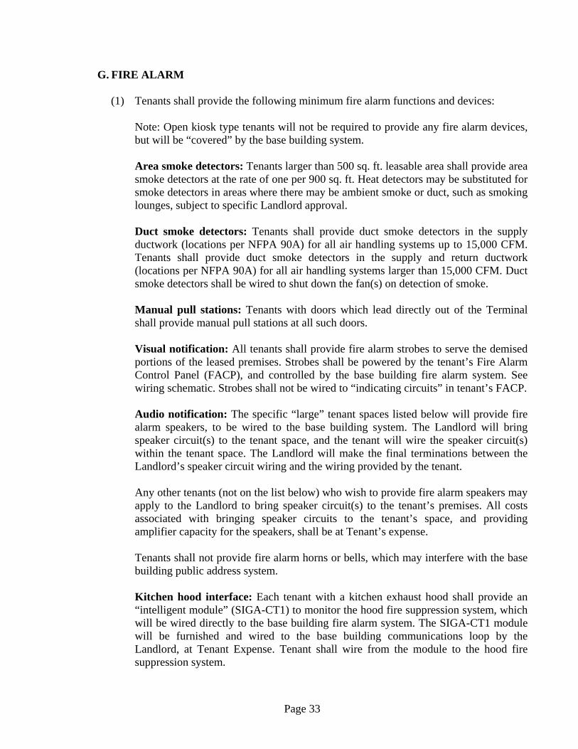
Area smoke detectors: Tenants larger than 500 sq. ft. leasable area shall provide area smoke detectors at the rate of one per 900 sq. ft. Heat detectors may be substituted for smoke detectors in areas where there may be ambient smoke or duct, such as smoking lounges, subject to specific Landlord approval.
Duct smoke detectors: Tenants shall provide duct smoke detectors in the supply ductwork (locations per NFPA 90A) for all air handling systems up to 15,000 CFM. Tenants shall provide duct smoke detectors in the supply and return ductwork (locations per NFPA 90A) for all air handling systems larger than 15,000 CFM. Duct smoke detectors shall be wired to shut down the fan(s) on detection of smoke.
Manual pull stations: Tenants with doors which lead directly out of the Terminal shall provide manual pull stations at all such doors.
Visual notification: All tenants shall provide fire alarm strobes to serve the demised portions of the leased premises. Strobes shall be powered by the tenant’s Fire Alarm Control Panel (FACP), and controlled by the base building fire alarm system. See wiring schematic. Strobes shall not be wired to “indicating circuits” in tenant’s FACP.
Audio notification: The specific “large” tenant spaces listed below will provide fire alarm speakers, to be wired to the base building system. The Landlord will bring speaker circuit(s) to the tenant space, and the tenant will wire the speaker circuit(s) within the tenant space. The Landlord will make the final terminations between the Landlord’s speaker circuit wiring and the wiring provided by the tenant.
Any other tenants (not on the list below) who wish to provide fire alarm speakers may apply to the Landlord to bring speaker circuit(s) to the tenant’s premises. All costs associated with bringing speaker circuits to the tenant’s space, and providing amplifier capacity for the speakers, shall be at Tenant’s expense.
Tenants shall not provide fire alarm horns or bells, which may interfere with the base building public address system.
Kitchen hood interface: Each tenant with a kitchen exhaust hood shall provide an “intelligent module” (SIGA-CT1) to monitor the hood fire suppression system, which will be wired directly to the base building fire alarm system. The SIGA-CT1 module will be furnished and wired to the base building communications loop by the Landlord, at Tenant Expense. Tenant shall wire from the module to the hood fire suppression system.
Page 34
(2) System configuration and wiring:
See Tenant Fire Alarm Wiring Schematic. The Landlord provides two “intelligent modules” (SIGA-CT1 and SIGA-CR) in each tenant space for monitoring and control of tenant fire alarm systems. Connections to the two modules shall be performed by Landlord’s contractor at Tenant’s expense. Each tenant will provide a fire alarm control panel (FACP), and will wire all initiating devices (except for kitchen hood interface) to the tenant’s FACP. The Tenant’s FACP will be monitored (for alarm and trouble) by the SIGA-CT1 module provided by the base building. Tenant strobes will be powered by the power supply in Tenant’s FACP, and will be controlled by the base building SIGA-CR module. “Large” tenants listed below will provide stand-alone addressable fire-alarm control panels (with individual addressable fire alarm devices), with interface to the base building system (monitoring and control of strobes) as described above. Addressable FACP locations shall be coordinated with Metro North, so that FACP will be reasonably accessible to the Police and Fire Departments.
The base building system is an Edwards Signature Series system. Tenants may provide FACPs (and equipment) by Edwards, Ademco, Gamewall, Notifier, or Simplex. Tenants are advised that Metro North maintenance staff is capable of maintaining Edwards equipment, at Tenant’s request; if equipment by other vendors is provided, Metro North may not be able to assist the Tenant.
(3) “Large” tenants: The Landlord will bring fire alarm audio notification (speaker)
circuits to the following tenant spaces. These tenants will also provide addressable fire alarm systems:
Space B-1 (Campbell Apartment) Spaces MC-7, MC-8, MC-9 and MC-10 Spaces B-54, B-56 and B-57 Space B-53 (Hall C, Restaurant #4)
(4) General: All fire alarm system installation and wiring shall comply with NFPA 72, the
National Electrical Code, and the Tenant Handbook.

Page 35

Page 36

Page 37
Page 38
III. SUSTAINABLE DESIGN CRITERIA A. General
(1) This guideline includes general requirements and procedures for compliance with certain USGBC LEED prerequisites and credits needed for Grand Central Terminal to obtain LEED certification based on the 2009 version of LEED – Interior Design and Construction for Retail applications.
B. Water Use Reduction:
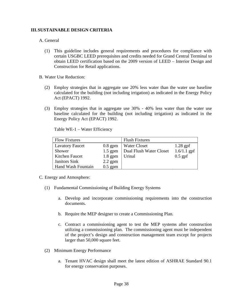
(2) Employ strategies that in aggregate use 20% less water than the water use baseline
calculated for the building (not including irrigation) as indicated in the Energy Policy Act (EPACT) 1992.
(3) Employ strategies that in aggregate use 30% - 40% less water than the water use
baseline calculated for the building (not including irrigation) as indicated in the Energy Policy Act (EPACT) 1992.
Table WE-1 – Water Efficiency Flow Fixtures Flush Fixtures Lavatory Faucet 0.8 gpm Water Closet 1.28 gpf Shower 1.5 gpm Dual Flush Water Closet 1.6/1.1 gpf Kitchen Faucet 1.8 gpm Urinal 0.5 gpf Janitors Sink 2.2 gpm Hand Wash Fountain 0.5 gpm
C. Energy and Atmosphere:
(1) Fundamental Commissioning of Building Energy Systems a. Develop and incorporate commissioning requirements into the construction
documents. b. Require the MEP designer to create a Commissioning Plan. c. Contract a commissioning agent to test the MEP systems after construction
utilizing a commissioning plan. The commissioning agent must be independent of the project’s design and construction management team except for projects larger than 50,000 square feet.
(2) Minimum Energy Performance
a. Tenant HVAC design shall meet the latest edition of ASHRAE Standard 90.1 for energy conservation purposes.
Page 39
b. Install ENERGY STAR qualified equipment for 50% of ENERGY STAR
eligible equipment. Eligible equipment includes appliances, office equipment, electronics and commercial food service equipment.
(3) Fundamental Refrigerant Management
a. The use of CFC refrigerants in Tenant HVAC systems is prohibited.
(4) Optimize Energy Performance – Lighting Power
a. Refer to Architectural Design Criteria for detailed information.
(5) Optimize Energy Performance – Lighting Controls
a. Refer to Architectural Design Criteria for detailed information.
(6) Optimize Energy Performance – HVAC
a. Tenant HVAC design shall incorporate one or both of the following strategies:
1. Option 1
i. Specify HVAC equipment that meets the New Building Institute, Inc.’s “Advanced Buildings Core Performance Guide Sections 1.4: Mechanical System Design, 2.9: Mechanical Equipment Efficiency and 3.10: Variable Speed Control.”
ii. Zone tenant fit out of spaces such that every solar exposure must
have a separate zone control, interior spaces are separately zoned and private offices and special occupancies (conference rooms, kitchens, etc.) must have active controls capable of sensing space use and modulating the HVAC system in response to space demand.
2. Option 2
i. Demonstrate that HVAC system component performance criteria used for tenant space are 15% or 30% better than ASHRAE standard 90.1-2007 or later.
(7) Enhanced Commissioning
a. Proceed with the following commissioning activities with a commissioning agent who is an independent firm from the MEP design firm:

Page 40
1. Conduct a commissioning design review of the owner’s project requirements, basis of design and design documents prior to the mid-construction documents phase and back-check the review comments in the subsequent design submission.
2. Conduct a review of the tenant spaces energy related systems
contractor submittals. 3. Develop a retro-commissioning plan. 4. Verify proper training will be given to facility staff for any new
energy related systems.
D. Indoor Environmental Quality (1) Minimum IAQ Performance
a. Meet the minimum requirements of ASHRAE Standard 62.1 – 2007, or latest
edition. (2) Outdoor Air Delivery Monitoring
b. Provide capacity for ventilation system monitoring to help sustain long term
occupant comfort and wellbeing by requiring the following:
1. Installation of a CO2 sensor for spaces equal or greater than 25 people/1,000 square feet.
2. Installation of an outdoor airflow measurement device measuring
within 15% of the design minimum out door air rate for all other spaces indicated above.
(3) Increased Ventilation
a. For Increased Ventilation credit, the ventilation shall be designed to deliver at
least 30% above ASHRAE standard 62.1 – 2007, or latest edition minimum ventilation rates.
(4) Construction IAQ Management Plan – During Construction
a. Prevent indoor air quality problems resulting from construction by requiring the
following measures:
1. Development and implementation of an Indoor Air Quality (IAQ) Management Plan.
Page 41
2. Construction process meets SMACNA IAQ Guidelines for Occupied Buildings Under Construction, 2nd Edition 2007.
3. The use of MERV 8 filters at each AHU if ran during construction. 4. Replace all filter media immediately prior to occupancy.
(5) Construction IAQ Management Plan – Before Occupancy
a. Reduce indoor air quality problems resulting from construction prior to
occupancy by requiring either one of the following two procedures: 1. Install new filtration media and conduct a flush-out of the tenant
space by supplying a total air volume of 14,000 CFM of outdoor air per square foot of floor area while maintaining an internal temperature of at least 60 F and, where mechanical cooling is operated, relative humidity no higher than 60%.
If occupancy is desired prior to completion of the flush out, the space may be occupied following a delivery of a minimum of 3,500 CFM of outside air per square foot of floor area. Once the space is occupied, it must be ventilated at a minimum rate of 0.30 CFM of outside air per square foot or the design minimum outside air rate determined in Minimum IAQ Performance, whichever is greater, until 14,000 CFM of outside air per square foot has been delivered to the space.
2. Conduct a baseline IAQ test measuring contaminants concentration
levels.
(6) Indoor Chemical and Pollutant Source Control a. Minimize exposure of building occupants to potentially hazardous particulates
by requiring the following: 1. Segregate janitorial areas with deck to deck portions with separate
ducted exhaust. 2. Provide regularly occupied areas of the tenant space with MERV 13
filtration.
(7) Controllability of Systems – Lighting
a. Refer to Architectural Design Criteria for detailed information. (8) Controllability of Systems – Thermal Comfort
Page 42
a. Tenant engineer shall design and provide a high level of thermal and ventilation
controls for individual’s occupants, and specific groups in multi-occupant spaces.
(9) Thermal Comfort – Design
a. Temperature and humidity levels shall comply with ASHRAE standard 55-
2004, or latest edition. (10) Thermal Comfort – Verification
a. A permanent monitoring system shall be provided to ensure HVAC system
complies with ASHRAE standard 55-2004, or latest edition. Agree to conduct a thermal comfort survey of tenant space occupants within 6 to 18 months after occupancy. Agree to develop a plan for corrective action if the survey results indicate that more than 20% of occupants are dissatisfied.

Page 43
IV. SPECIAL DESIGN AND INSTALLATION CRITERIA FOOD SERVICE TENANTS
The preceding Criteria apply to work by all tenants. These special design and installation criteria apply to certain work performed only by Food Service Tenants in addition to all of the requirements of the other Criteria above.
A. KITCHEN EQUIPMENT
(1) Tenant design drawings shall include Kitchen Equipment Plans and a Kitchen
Equipment List, identifying and providing the following information for each item of kitchen equipment: Item number, description, manufacturer, model number, and utility requirements (piping connections, electrical voltage, phase, amperage, horsepower, etc.). Tenant shall submit catalog cut sheets for each item of kitchen equipment. Cut sheets shall be tagged with item numbers coordinated with the equipment list on Tenant’s drawings, and shall include photographs or drawings, complete dimensional information, and utility requirements.
(2) Tenant’s submission to Landlord shall include:
a. Complete list of all gas-fired equipment, giving make, model, description, rated
input, and quantity of each item of gas equipment b. Manufacturer’s cut sheets for each item of gas-fired equipment indicating model
numbers, dimensions, and rated gas input c. Class K fire extinguishers.
(3) All gas-fired equipment furnished and/or installed by Tenant must have A.G.A and
M.E.A. approval. Evidence of such approval must be visible on the nameplate of any gas-fired equipment delivered to the Premises and on equipment cut sheets submitted to the Landlord for review.
B. KITCHEN EXHAUST AND MAKE-UP
(1) Restaurant and Cafe Tenants:
a. Restaurant and Café tenants shall provide individual kitchen exhaust systems
where kitchen exhaust is permitted under the Specific Area Criteria. Landlord shall provide a kitchen exhaust duct from Tenant’s Premises to outdoors as described in the Specific Area Criteria for each area. Where Tenant’s exhaust fan will be located in Landlord’s mechanical equipment space, Tenant will furnish the fan and Landlord shall install the fan at Tenant’s expense. Tenant shall provide all required system elements within the Tenant’s Premises. Where Tenant’s hood exhaust requirement is less than the exhaust quantity required to maintain the Code minimum air velocity of 1,500 ft/min at all points in the exhaust ductwork, Tenant shall provide a direct make-up air connection to the

Page 44
exhaust duct as shown in the Make-up Air Bypass Detail to increase the air velocity in the duct to the Code minimum.
Tenant is responsible to coordinate his duct routing and exhaust fan location(s) with Landlord, working within the allocated areas as shown on the Lease Outline Drawing, and for making such openings as are required for Tenant’s ductwork and resealing partitions at those openings.
b. All kitchen exhaust fans shall be provided with ¾” drain and gasketed cleanout
door, and shall be installed in accordance with NFPA 96 and all applicable Codes. Drains shall be capped for intermittent manual cleaning, or piped to a grease interceptor, subject to space and plumbing system availability. Tenant fans and ductwork must not drip grease on Landlord’s building or roof.
c. Where make-up air is provided by the Landlord: Tenant’s system shall be
designed and constructed so that 85% of the kitchen hood exhaust air quantity will be replaced by Tenant furnished and installed make-up air systems to prevent the migration of odors and/or heat and cooling to other occupied premises or to the public area. The remaining 15% of the exhaust quantity shall be drawn from the public area. Landlord will furnish and install a make-up air intake duct system with a connection for each Restaurant and Cafe Tenant. (See Lease Outline Drawings and Base Building Drawings). Landlord shall provide a make-up air unit in Landlord’s mechanical equipment room at Tenant’s expense. Tenant shall provide all other required system elements. The make-up unit shall provide steam heat, but not air conditioning. Tenant shall provide a steam meter and shall pay the operating costs of the make-up air unit. Tenant may provide chilled water duct coil(s) for the make-up air system within Tenant’s premises, as field conditions permit. Tenant’s make-up air unit shall be interlocked with Tenant’s exhaust fan to run together and be controlled by a single operating control in Tenant’s premises. There shall be no local control for the make-up air fans readily accessible for operation by the occupants.
d. Restaurant and Cafe Tenant’s HVAC system shall be equipped by tenant with
smoke detectors and engineered smoke control provisions for Tenant’s Premises as required by Code. Where, and if, required by Code or the authority having jurisdiction, Landlord will provide, at Tenant’s expense, extension and/or expansion of the main building fire alarm and monitoring system to cover Tenant’s Premises.
(2) Lower Concourse Food Retail and Cafe Tenants:
a. Food Retail and Cafe Tenants with food cooking equipment (including ovens,
grilles, fryers, etc.) shall provide kitchen exhaust hoods. Landlord will provide a master kitchen exhaust duct and fan system with provisions to serve each Food Retail and Café Tenant, as indicated in the Specific Area Criteria. Tenant will provide branch ductwork to connect to his kitchen hood(s). Because there is no

Page 45
means to adjust airflow to individual tenant exhaust hoods on the master exhaust system, Tenant shall carefully coordinate his exhaust hood selection and the design and installation of Tenant’s exhaust ductwork with Landlord to match Tenant’s system to the capabilities of Landlord’s system.
b. When directed by Landlord, Tenant shall provide a direct bypass air connection
to the master exhaust duct within Tenant’s premises, as shown in the Make-up Air Bypass/Non-Grease Exhaust Branch Connection Detail. Direct bypass air connections will be required in some locations to achieve Code minimum air velocity in the main exhaust ductwork.
c. Landlord provides no independent source of make-up air to replace Tenant
kitchen exhaust. All make-up air shall be drawn from the Common Areas. Tenant’s design must provide adequate open area to permit passage of air from the Common Areas to Tenant’s hood, with air velocity not exceeding 400ft. /min. through any opening.
d. At the completion of Tenant’s construction, Landlord’s balancing contractor
will measure Tenant’s exhaust airflow and adjust direct bypass connections, at Tenant’s expense.
(3) All Food Service Tenants:
a. All cooking Tenants will design and install kitchen exhaust and makeup air
systems in accordance with the following.
1. Design and installation of the entire kitchen exhaust system must comply with all applicable codes.
2. Kitchen hoods installed by tenants must be factory fabricated, tested
and approved for the purpose, and bear evidence of UL approval. Shop fabricated hoods are not acceptable. Exhaust hoods for Lower Concourse Food Retail and Cafe tenants shall be UL Listed hoods with fire damper.
3. Tenant shall furnish, install and maintain in proper working order, a
Listed wet or dry chemical fire extinguishing system, or an equivalent approved system, to protect all cooking equipment, kitchen hoods, and exhaust ductwork. Fire extinguishing system must be approved by Landlord, and meet the requirements of NFPA 96, applicable Codes, and Landlord’s insurance carrier. Tenant’s make-up air fan must shut off upon actuation of Tenant’s hood fire protection system.

Page 46
4. Actuation of Tenant’s kitchen hood fire suppression system shall shut off the fuel supply to all equipment under the hood, including gas and electric elements such as outlets that are used or not used.
5. Internal (“short circuit”) make-up air supply to Tenant hoods shall be
limited to the difference between the total hood exhaust and an estimate of the minimum airflow required to completely capture the thermal plume produced by the cooking equipment under the hood. In no case shall short circuit make-up air supply exceed 30% of the hood exhaust.
6. Tenant shall provide electric heating coils, steam heating coils
(where steam is available), or direct fired natural gas heat to heat any makeup air not introduced directly into short-circuit exhaust hoods, to heat the make-up air to at least 65°F. Indirect fired gas furnaces requiring a flue connection will not be allowed for heating makeup air.
b. Kitchen exhaust and make-up air ductwork furnished and installed by the tenant
shall be constructed and installed according to the following criteria:
1. Make-up air ductwork and ductwork for exhaust systems designed for odor or heat removal only shall be fabricated from galvanized sheet metal in strict accordance with the current Duct Construction Standards of the Sheet Metal and Air Conditioning Contractors National Association of America. Tenant will insulate make-up air and exhaust ductwork and plenums in accordance with the HVAC Criteria above.
2. Grease exhaust ductwork shall be constructed in accordance with
NFPA 96 and the New York City Building Code (16 ga. up to 155 sq. in. cross-sectional duct area, 14 ga. up to 200 sq. in., 12 ga. up 255 sq. in., and 10 ga. greater than 255 sq. in.) Continuously weld all longitudinal joints. Weld all transverse joints or provide flanges with 2”x2”x1/8” structural rolled angles with high temperature gasket and sealer. Where applicable, ducts shall be enclosed in a fire resistance rated enclosure as required by NFPA 96.
3. Ductwork for dishwasher exhaust shall be rectangular low pressure
type 304 stainless steel or aluminum ductwork of 24 gage minimum thickness. Ductwork shall be properly pitched to drain to the hood connection with all longitudinal joints soldered and all transverse joints welded. Dishwasher duct shall connect to Tenant’s grease exhaust duct, with fire damper and volume dampers as shown in the Make-up Air Bypass/Non-Grease Exhaust Branch Connection Detail.
Page 47
4. Extra care must be taken with the appearance of all ductwork
exposed to public view from the surrounding areas or from above. Ducts must be only spiral duct or rectangular sheet metal construction. Joints and seams must have a neat, completely finished appearance. Hangers must be evenly spaced and neatly finished off. Hanger types and location must be shown in detail on plans submitted for Landlord review, and all hangers and support systems are subject to Landlord’s approval for visual coordination. No strap type hangers will be permitted.
c. Cleanout doors shall be provided by Tenant on the side of the grease exhaust
duct no greater than 12 ft intervals, on center, for horizontal ductwork, at each change of direction of the duct, and on each floor for vertical ductwork. Access shall be provided at the top of the vertical riser to accommodate descent. Bottom edge of cleanout door shall be not less than 2” above the bottom of the duct. Every tenant shall have at least one cleanout door. Provide a cleanout door and grease drain at the base of each vertical section of kitchen exhaust duct. Provide 1/8” thick high temperature gasket, approved for use on kitchen exhaust ducts, between frame and duct and between door and frame.
d. Tenants providing water wash type hoods must provide direct connected hot
and cold water supply lines, as recommended by the grease extractor manufacturer, and a full size waste water connection running to a grease trap above the floor provided by Tenant in Tenant’s Premises.
e. Display cooking under a kitchen hood will be allowed in the display zone of
Tenant’s premises only if the installation makes adequate provision for safety and hygiene, and is arranged so that it will not have a deleterious effect on Common Area air conditioning. Refer to Display Cooking Kitchen Hood Diagram for Additional Criteria. Restaurant and Cafe tenants may locate Display Cooking anywhere within the enclosed storefront of the Leased Premises, providing the same installation requirements are observed. Display cooking will be permitted in Food Retail tenant spaces only with Landlord’s specific review and written approval.
1. Tenant’s engineer shall refer to the Tenant Architectural Design
Criteria for guard panel specifications. Guard panels shall be located on the display cooking surface as described the Tenant Architectural Design Criteria to protect the public from any spatter, to separate the cooking surface from the public area, and to provide better containment of smoke and fumes generated in the cooking process. Guard panels should extend from below the height of the cooking surface to within ½” of the lower edge of the hood.
Page 48
2. Kitchen Hood inlet area must exceed the cooking area on all sides to provide proper capture. Provide at least 9” clearance between the inside edge of the hood and the outside edge of the cooking surface on each of the three sides with guards. Inside edge of the kitchen hood opening (inside edge of makeup air plenum) should overhang the edge of the cooking surface on the operator side by 12”.
f. Balancing, testing and commissioning criteria for kitchen exhaust to be
performed by a Landlord approved commissioning agent:
1. Review the installed exhaust fan technical data to confirm flow rate capacity characteristics.
2. Review the existing sequence of operations for the various typical
modes (occupied and emergency/standby) of operation. 3. Review the existing system documents and generate a survey plan
for implementation. In the event as-builts or accurate single-line documents are inaccurate, we will work with the Operations staff to generate a representative working red-line sketch for use during evaluation.
4. Coordinate with Engineering to determine the section of duct for
each space connected to the exhaust fan system and survey the ductwork associated to highlight areas that vary from design.
5. Perform a vibration analysis of the installed exhaust fan. 6. Instrumentation will be utilized to measure and record vibration
levels, in velocity, displacement, and acceleration on all bearings in the vertical, axial, and horizontal planes at the highest speed, and if required at other critical frequencies associated with drives.
7. All equipment faults detected will be scrutinized to determine the
cause of the fault and to provide a recommendation for corrective action by a contractor.
8. A comprehensive report is then issued with a complete description of
the mechanical operating conditions, the causes of the faults, and the recommended solutions.
9. Review the existing contractor performed start-up, testing and/or
ongoing maintenance documentation for the installed exhaust fan and dampers to baseline evaluation parameters.
10. Present a preliminary Evaluation Report for review by Engineering.

Page 49
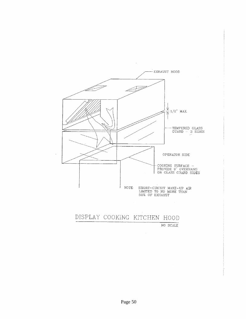
Page 50

Page 51
V. SPECIFIC AREA CRITERIA A. Main Concourse
(1) Incoming Concourse/Main Train Room (MC-1A, 1B, 1D, 1E, MC-2 – MC-4)
HVAC
The Landlord provides a complete HVAC system to serve the large open space of the Incoming Train Room (spaces MC-1 – MC-1E)
Tenants in spaces MC-2 – MC-4 shall provide their own complete HVAC systems as needed. Up to 0.016 gpm chilled water per sq. ft GLA is available. Landlord provides an outside air duct to a point in or adjacent to Tenant’s premises, with sufficient capacity to deliver 0.3 CFM outside air per sq. ft. GLA. Outside air is heated to 45°F in the winter, and is not conditioned. Tenant shall provide an approved constant airflow regulator on the outside air supply. Tenant shall provide all equipment, ductwork, controls, and accessories as required Tenant’s system. Tenant’s requiring space heat shall provide electric heat.
Kitchen exhaust is not available. Cooking requiring exhaust to outdoors is not permitted.
PLUMBING
Plumbing services listed below are available for the following spaces: MC-1A and MC-2
Gas is not available Water Connection 1” Sewer Connection 3” Vent Connection 2” ELECTRICAL
Maximum design capacity for Tenant’s electrical system: Space MC-1: 12 va/sq. ft Other spaces: 40 va/sq. ft.
Refer to diagram ED-1.
Landlord provides empty ¾” telephone raceway from Tenant’s premises to Landlord’s telephone room. All Tenant telephone equipment shall be located within Tenant’s premises. Tenant shall arrange telephone service directly with the telephone company.

Page 52
(2) Biltmore Room (MC-1)
HVAC
The Landlord provides a complete HVAC system to serve the large open space of the Incoming Train Room (spaces MC-1 – MC-1E). Currently air handling unit AH-1, located in the mechanical room 28217, is providing 16,000 CFM of conditioned air to the space. The cooling coil for AH-1 is rated for 544 MBH. The design entering air temperature is 80ºDB/ 67ºWB. The design supply temperature to the space is 57.4ºDB/56.1ºWB. AH-1 is also responsible for the only outside air delivered to the space. Outside air is delivered to AH-1 via fan S-01 which is located in room 281-P northwest of the BR. S-01 is designed to supply 4,000 CFM to the mechanical room housing AH-1. Outside air is heated to 45°F in the winter, and is not conditioned
If desired, Tenant may provide additional supplemental cooling or heating in the space at Tenant’s expense. Installation of supplemental air conditioning systems must comply with the restrictions on alteration of the building’s historic elements. The use of CFC refrigerants for supplemental HVAC equipments is prohibited. Supplemental cooling systems should be designed to deliver relatively cool air (65°-68°F) at relatively low velocity, to minimize uncomfortable drafts, and should draw return air relatively close to the floor. Supplemental cooling shall be provided via air cooled DX equipment. Chilled water is not available for supplemental cooling. Kitchen exhaust is not available. Cooking requiring exhaust to outdoors is not permitted.
PLUMBING
Plumbing services listed below are available for the following spaces: MC-1A and MC-2
Gas is not available Water Connection 1” Sewer Connection 3” Vent Connection 2” ELECTRICAL
Maximum design capacity for Tenant’s electrical system: Space MC-1: 12 va/sq. ft Other spaces: 40 va/sq. ft.
Refer to diagram ED-1.
Landlord provides empty ¾” telephone raceway from Tenant’s premises to Landlord’s telephone room. All Tenant telephone equipment shall be located within

Page 53
Tenant’s premises. Tenant shall arrange telephone service directly with the telephone company.
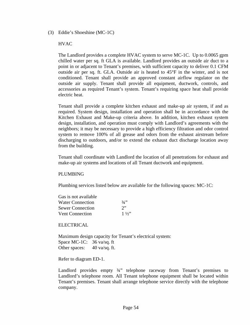
Page 54
(3) Eddie’s Shoeshine (MC-1C) HVAC
The Landlord provides a complete HVAC system to serve MC-1C. Up to 0.0065 gpm chilled water per sq. ft GLA is available. Landlord provides an outside air duct to a point in or adjacent to Tenant’s premises, with sufficient capacity to deliver 0.1 CFM outside air per sq. ft. GLA. Outside air is heated to 45°F in the winter, and is not conditioned. Tenant shall provide an approved constant airflow regulator on the outside air supply. Tenant shall provide all equipment, ductwork, controls, and accessories as required Tenant’s system. Tenant’s requiring space heat shall provide electric heat.
Tenant shall provide a complete kitchen exhaust and make-up air system, if and as required. System design, installation and operation shall be in accordance with the Kitchen Exhaust and Make-up criteria above. In addition, kitchen exhaust system design, installation, and operation must comply with Landlord’s agreements with the neighbors; it may be necessary to provide a high efficiency filtration and odor control system to remove 100% of all grease and odors from the exhaust airstream before discharging to outdoors, and/or to extend the exhaust duct discharge location away from the building.
Tenant shall coordinate with Landlord the location of all penetrations for exhaust and make-up air systems and locations of all Tenant ductwork and equipment.
PLUMBING
Plumbing services listed below are available for the following spaces: MC-1C:
Gas is not available Water Connection ¾” Sewer Connection 2” Vent Connection 1 ½” ELECTRICAL
Maximum design capacity for Tenant’s electrical system: Space MC-1C: 36 va/sq. ft Other spaces: 40 va/sq. ft.
Refer to diagram ED-1.
Landlord provides empty ¾” telephone raceway from Tenant’s premises to Landlord’s telephone room. All Tenant telephone equipment shall be located within Tenant’s premises. Tenant shall arrange telephone service directly with the telephone company.

Page 55
(4) Small Retail Incoming Concourse (MC-5, MC-6)
Shuttle Passage (MC-7, MC-15, MC-17) Main Concourse (MC-11 – MC-14, MC-21 - MC-25) 42nd Street Passage (MC-26 – MC-30) Graybar Passage (MC-31 – MC- 39) Lexington Passage (MC-60 - MC-86) Vanderbilt Entry (B-60) 43rd & Vanderbilt (V-72)
HVAC
Landlord provides each tenant either chilled water and outside air, or a bypass variable air volume (VAV) box which delivers conditioned supply air. Refer to page 35 for a plan indication which Graybar and Lexington Passage tenants receive VAV supply air. All other tenants receive chilled water and outside air. Outside air to spaces MC-2, 3, 4, 5, and 7 is not preheated.
Chilled Water Tenants:
Each tenant shall provide his own complete heating and air conditioning system. Up to 0.012 gpm chilled water per sq. ft. GLA is available. Landlord provides an outside air duct to a point in or adjacent to Tenant’s premises, with sufficient capacity to deliver 0.3 CFM outside air per sq. ft GLA Outside air is heated to 45°F in the Winter, and is not conditioned. Tenant shall provide an approved constant airflow regulator on the outside air supply. Tenant shall provide all equipment, ductwork, controls, and accessories as required for Tenant’s system. Tenant’s requiring space heat shall provide electric heat.
VAV Tenants:
Landlord provides one or more bypass VAV boxes in Tenant’s premises, with a thermostat temporarily mounted at the VAV box. Tenant shall provide ductwork, diffusers, and accessories as required, and shall reinstall the thermostat on the wall. Tenants requiring space heat shall provide electric heat. Up to 2.5 CFM per sq. ft. GLA is available.
Toilet exhaust and kitchen exhaust are not available.
PLUMBING
Gas is not available Water Connection min. ¾” Sewer Connection min. 2” Vent Connection min. 2”

Page 56
Refer to Lease Outline Drawings for exact connection sizes.
ELECTRICAL
Electrical Service: 120/208V, 3-ph, 4-wire. Refer to ED-1.
Maximum design capacity for Tenant’s electrical system: Space MC-6, MC-11, MC-17, MC-30, MC-73 = 45 va/sq ft Spaces MC-15, MC-31 = 75 va/sq ft All other spaces = 16 va/sq. ft.
Landlord provides empty ¾” telephone raceway from Tenant’s premises to Landlord’s telephone room. All Tenant telephone equipment shall be located within Tenant’s premises. Tenant shall arrange telephone service directly with the telephone company.
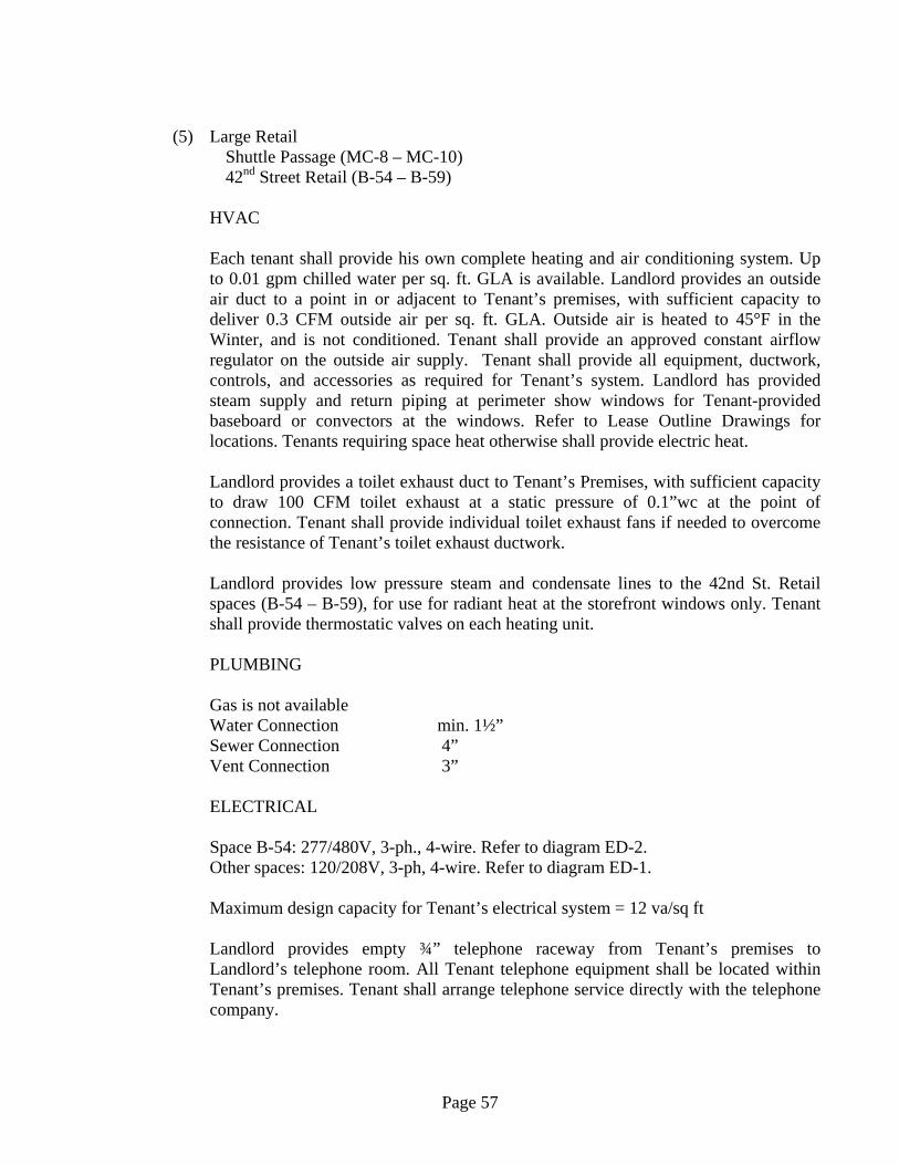
Page 57
(5) Large Retail
Shuttle Passage (MC-8 – MC-10) 42nd Street Retail (B-54 – B-59)
HVAC
Each tenant shall provide his own complete heating and air conditioning system. Up to 0.01 gpm chilled water per sq. ft. GLA is available. Landlord provides an outside air duct to a point in or adjacent to Tenant’s premises, with sufficient capacity to deliver 0.3 CFM outside air per sq. ft. GLA. Outside air is heated to 45°F in the Winter, and is not conditioned. Tenant shall provide an approved constant airflow regulator on the outside air supply. Tenant shall provide all equipment, ductwork, controls, and accessories as required for Tenant’s system. Landlord has provided steam supply and return piping at perimeter show windows for Tenant-provided baseboard or convectors at the windows. Refer to Lease Outline Drawings for locations. Tenants requiring space heat otherwise shall provide electric heat.
Landlord provides a toilet exhaust duct to Tenant’s Premises, with sufficient capacity to draw 100 CFM toilet exhaust at a static pressure of 0.1”wc at the point of connection. Tenant shall provide individual toilet exhaust fans if needed to overcome the resistance of Tenant’s toilet exhaust ductwork.
Landlord provides low pressure steam and condensate lines to the 42nd St. Retail spaces (B-54 – B-59), for use for radiant heat at the storefront windows only. Tenant shall provide thermostatic valves on each heating unit.
PLUMBING Gas is not available Water Connection min. 1½” Sewer Connection 4” Vent Connection 3”
ELECTRICAL
Space B-54: 277/480V, 3-ph., 4-wire. Refer to diagram ED-2. Other spaces: 120/208V, 3-ph, 4-wire. Refer to diagram ED-1.
Maximum design capacity for Tenant’s electrical system = 12 va/sq ft
Landlord provides empty ¾” telephone raceway from Tenant’s premises to Landlord’s telephone room. All Tenant telephone equipment shall be located within Tenant’s premises. Tenant shall arrange telephone service directly with the telephone company.
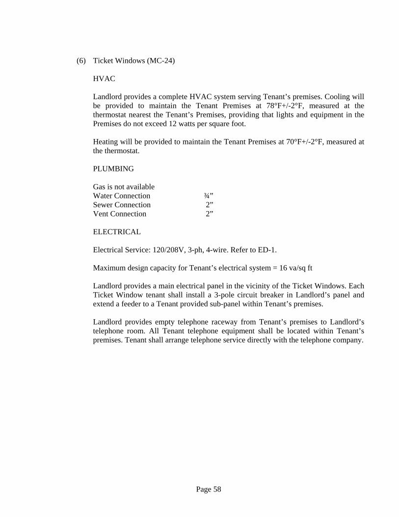
Page 58
(6) Ticket Windows (MC-24)
HVAC
Landlord provides a complete HVAC system serving Tenant’s premises. Cooling will be provided to maintain the Tenant Premises at 78°F+/-2°F, measured at the thermostat nearest the Tenant’s Premises, providing that lights and equipment in the Premises do not exceed 12 watts per square foot.
Heating will be provided to maintain the Tenant Premises at 70°F+/-2°F, measured at the thermostat.
PLUMBING
Gas is not available Water Connection ¾” Sewer Connection 2” Vent Connection 2”
ELECTRICAL
Electrical Service: 120/208V, 3-ph, 4-wire. Refer to ED-1.
Maximum design capacity for Tenant’s electrical system = 16 va/sq ft
Landlord provides a main electrical panel in the vicinity of the Ticket Windows. Each Ticket Window tenant shall install a 3-pole circuit breaker in Landlord’s panel and extend a feeder to a Tenant provided sub-panel within Tenant’s premises.
Landlord provides empty telephone raceway from Tenant’s premises to Landlord’s telephone room. All Tenant telephone equipment shall be located within Tenant’s premises. Tenant shall arrange telephone service directly with the telephone company.

Page 59
(7) Vanderbilt Room (Waiting Room)
HVAC
Cooling will be provided to maintain Tenant’s Premises at 78°F +/-2°F, measured at the thermostat nearest Tenant’s Premises, providing that Tenant provided lights and equipment in Tenant’s Premises do not exceed 15 watts per square foot.
Heating will be provided to maintain the Tenant Premises at 70°F+/-2°F, measured at the thermostat.
PLUMBING
No plumbing is available.
ELECTRICAL
One 120V, 20A dedicated duplex receptacles will be provided for each kiosk location.
One data/telephone outlet with capacity for two telephone lines will be provided for each kiosk location. Tenant shall arrange for telephone service through Landlord’s telephone service vendor.
Page 60
(8) Roosevelt Passage (MC-90 – MC-920
HVAC/Plumbing
No HVAC or Plumbing services are provided to Roosevelt Passage Tenants.
ELECTRICAL
Service: 120/208V, 3-ph, 4-wire. Refer to ED-1.
Maximum design capacity for Tenant’s electrical system = 16 va/sq ft
Landlord provides empty ¾” telephone raceway from Tenant’s premises to Landlord’s telephone room. All Tenant telephone equipment shall be located within Tenant’s premises. Tenant shall arrange telephone service directly with the telephone company.

Page 61
B. Major Restaurants (1) Balcony Restaurants (2) Campbell Apartment
HVAC
Each Balcony Restaurant Tenant shall provide his own complete heating and air conditioning system for all portions of Tenant’s premises other than the open balcony areas.
Balcony areas:
The Main Concourse will be heated and air conditioned by the Landlord. The Landlord’s system will provide fresh air and is designed to maintain conditions no higher than 78°F and 55% RH at the floor level of the Main Concourse in accordance with the N.Y. State Energy Code design criteria. However, the Landlord’s HVAC system is not designed to maintain comfort conditions in the balcony seating areas without supplemental cooling. For the East and West balconies, the Landlord has provided supplementary fan coil units. These units are installed consistent with the landmark architecture and will provide approximately 11.5 tons of additional cooling and 192 MBH heating. Base building drawings are available for review. Tenant should request intentions to modify the controls and/or discharge grilles of the fan coil units on the design drawings. The Landlord will make any agreed upon modifications.
If desired, Tenant may provide additional supplemental cooling or heating in the balcony seating areas. Installation of supplemental air conditioning systems must comply with the restrictions on alteration of the building’s historic elements. The use of CFC refrigerants for supplemental HVAC equipments is prohibited. Where Tenant will build platforms to create raised seating areas above the balcony, the supplemental cooling may be incorporated into the platforms, with floor registers on top of the platform and low sidewall registers on the sides of the platforms facing lower seating areas. With some care, the platform structure itself may serve as a pressurized supply air plenum, eliminating the need for ductwork within the platform. Supplemental cooling systems should be designed to deliver relatively cool air (65°-68°F) at relatively low velocity, to minimize uncomfortable drafts, and should draw return air relatively close to the floor.
The Landlord provides chilled water and steam for Tenant’s use to provide complete HVAC for the rest of Tenant’s premises, and to provide supplemental cooling for the balcony seating areas. Landlord provides chilled water and steam for heating. Tenant shall provide meters to record chilled water and steam usage, as described elsewhere in this handbook.
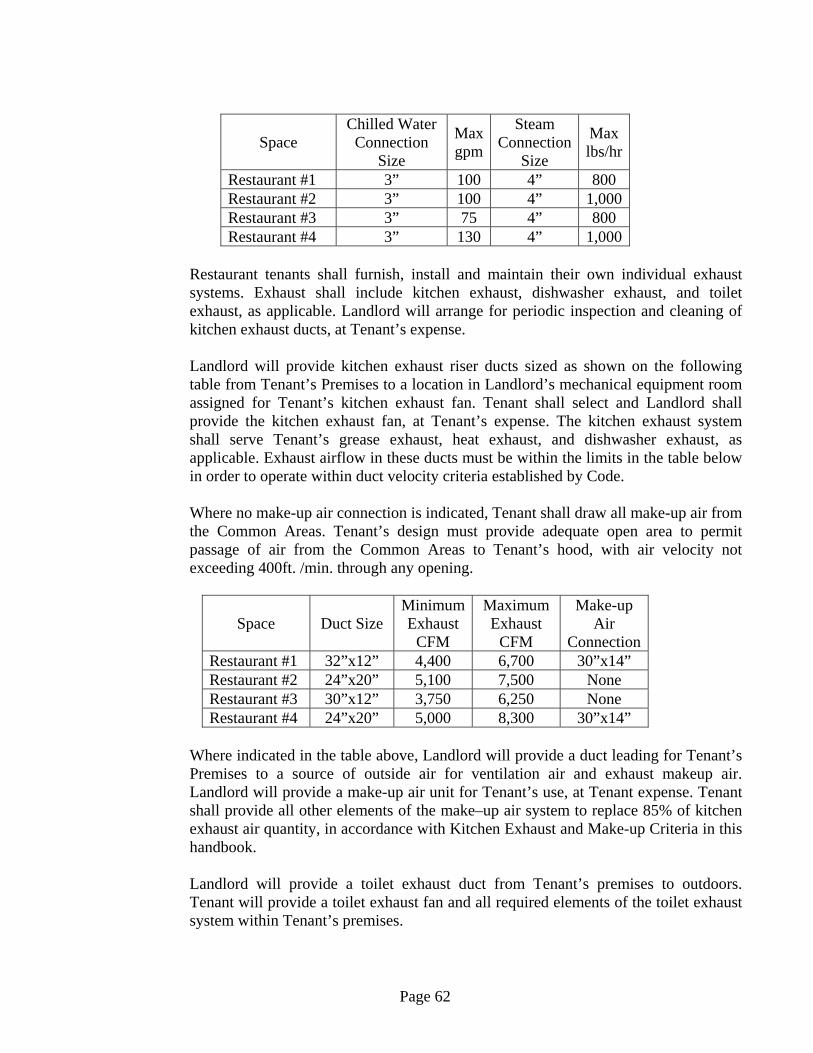
Page 62
Space Chilled Water
Connection Size
Max gpm
Steam Connection
Size
Max lbs/hr
Restaurant #1 3” 100 4” 800 Restaurant #2 3” 100 4” 1,000 Restaurant #3 3” 75 4” 800 Restaurant #4 3” 130 4” 1,000
Restaurant tenants shall furnish, install and maintain their own individual exhaust systems. Exhaust shall include kitchen exhaust, dishwasher exhaust, and toilet exhaust, as applicable. Landlord will arrange for periodic inspection and cleaning of kitchen exhaust ducts, at Tenant’s expense.
Landlord will provide kitchen exhaust riser ducts sized as shown on the following table from Tenant’s Premises to a location in Landlord’s mechanical equipment room assigned for Tenant’s kitchen exhaust fan. Tenant shall select and Landlord shall provide the kitchen exhaust fan, at Tenant’s expense. The kitchen exhaust system shall serve Tenant’s grease exhaust, heat exhaust, and dishwasher exhaust, as applicable. Exhaust airflow in these ducts must be within the limits in the table below in order to operate within duct velocity criteria established by Code. Where no make-up air connection is indicated, Tenant shall draw all make-up air from the Common Areas. Tenant’s design must provide adequate open area to permit passage of air from the Common Areas to Tenant’s hood, with air velocity not exceeding 400ft. /min. through any opening.
Space Duct Size Minimum Exhaust
CFM
Maximum Exhaust
CFM
Make-up Air
Connection Restaurant #1 32”x12” 4,400 6,700 30”x14” Restaurant #2 24”x20” 5,100 7,500 None Restaurant #3 30”x12” 3,750 6,250 None Restaurant #4 24”x20” 5,000 8,300 30”x14”
Where indicated in the table above, Landlord will provide a duct leading for Tenant’s Premises to a source of outside air for ventilation air and exhaust makeup air. Landlord will provide a make-up air unit for Tenant’s use, at Tenant expense. Tenant shall provide all other elements of the make–up air system to replace 85% of kitchen exhaust air quantity, in accordance with Kitchen Exhaust and Make-up Criteria in this handbook. Landlord will provide a toilet exhaust duct from Tenant’s premises to outdoors. Tenant will provide a toilet exhaust fan and all required elements of the toilet exhaust system within Tenant’s premises.

Page 63
Design and installation of HVAC system must comply with specific restrictions on equipment and duct locations shown on the Lease Outline Drawings. PLUMBING Gas is available on request 2200 CFH @ 8”wc Gas Connection 4” Water Connection 2” Sewer Connection 4” Vent Connection 3” ELECTRICAL Maximum design capacity for each tenant’s electrical system for Tenant’s lights and equipment (277/480V, 3-ph, 4 wire) = 35 va/sq ft Landlord shall provide an empty raceway from Landlord’s electric room to Tenant’s premises. Tenant shall provide an electrical feeder from Landlord’s electric room to Tenant’s premises in the Landlord’s raceway, and shall provide all elements of the electrical system within Tenant’s premises, as indicated in Diagram ED-2. The following table lists the approximate lengths of the empty conduits form Landlord’s electric room to Tenant’s premises:
Space Max.
Service (A)
Approx. length of
empty raceway
Approx. terminus of empty raceway
Restaurant #1 400 100 ft. Campbell Apt. Restaurant #2 400 400 ft. Hall A Restaurant #3 400 50 ft. Hall B Restaurant #4 400 100 ft. North side of East
Balcony Landlord provides empty ¾” telephone raceway from Tenant’s premises to Landlord’s telephone room. All Tenant telephone equipment shall be located within Tenant’s premises. Tenant shall arrange telephone service directly with the telephone company.
Page 64
C. Grand Central Market
REFIGERATION EQUIPMENT
All Tenant refrigeration equipment, including walk-in coolers and freezers, refrigerated display cases, and ice makers, with compressors rated greater than ¼ HP (or with rated power input greater than 700 va) shall be supplied by Tenant with remote refrigeration condensing units. Tenant shall install refrigeration condensing units on the roof above the second floor of the Market building, or racks provided by the Landlord. Tenant shall install refrigeration and electrical lines to the roof through chases and roof openings provided by the Landlord.
All walk-in coolers and freezers shall be provided with insulated floor panels.
HVAC
Landlord will provide a complete HVAC system to maintain the Common Areas of the Grand Central Market and Tenant’s Display Zone between 70°F and 78°F, measured at the thermostat nearest Tenant’s Premises, provided that heat gain from Tenant lighting and equipment located in the Display Zone (diversified load) does not exceed the equivalent of 25 watts per square foot of that area.
Additionally, for those Grand Central Market Tenants whose space includes a Work Zone, Landlord provides one capped air conditioning branch duct connection, with balancing damper, from Landlord’s low pressure distribution ductwork. Tenant shall extend to Tenant’s Work Zone as required, to provide up to 2 CFM supply air per sq. ft. of the Work Zone.
No cooking is permitted in the Grand Central Market.
No exhaust is available in the Grand Central Market.
PLUMBING
Gas is not available Water Connection 1” Sewer Connection 3” Vent Connection 2”
Landlord will provide at least one floor drain in or accessible to the Display Zone of Tenant’s Premises.
ELECTRICAL
Landlord will provide a 120/208V, 3-ph, 4-wire feeder form Landlord’s electrical room to a circuit breaker panel in or near Tenant’s premises (as indicated on the Lease Outline
Page 65
Drawings), a main circuit breaker in Tenant’s panel, and an electric meter on Tenant’s main feeder, located in Landlord’s electric room. The feeder and main circuit breaker will be either 60A or 100A, depending on Tenant’s GLA. Tenant shall provide branch circuit breakers and wiring as required for Tenant’s lighting and electrical equipment, including Landlord provided lighting track in Tenant’s premises. All wiring passing through other Tenant spaces or Common Areas will be installed by the Landlord at Tenant’s expense.
Maximum design capacity for Tenant’s electrical system = 50 va/sq ft
Landlord provides empty ¾” telephone raceway from Tenant’s premises to Landlord’s telephone room. All Tenant telephone equipment shall be located within Tenant’s premises. Tenant shall arrange telephone service directly with the telephone company.
Page 66
D. Upper Level 43rd St. Market (416 Lexington Street)
HVAC
Landlord provides a complete HVAC unit for 416 Lexington Ave. tenant, at Tenant’s expense. Tenant shall provide ductwork, diffusers, additional controls, and accessories as needed, and shall adjust the unit operation as needed to meet Tenant’s needs.
Tenant shall provide a complete toilet exhaust system as needed.
Tenant shall provide a complete kitchen exhaust and make-up air system, if and as required. System design, installation and operation shall be in accordance with the Kitchen Exhaust and Make-up criteria above. In addition, kitchen exhaust system design, installation, and operation must comply with Landlord’s agreements with the neighbors; it may be necessary to provide a high efficiency filtration and odor control system to remove 100% of all grease and odors from the exhaust airstream before discharging to outdoors, and/or to extend the exhaust duct discharge location away from the building.
Tenant shall coordinate with Landlord the location of all roof penetrations for exhaust and make-up air systems and locations of all Tenant ductwork and equipment on the roof. All roofing work shall be performed by Landlord’s selected roofing contractor, at Tenant’s expense.
PLUMBING
Gas is available on request 2200 CFH @ 8”wc Gas Connection 4”
Water Connection 2” Sewer Connection 4” Vent Connection 3”
ELECTRICAL
Service: 277/480V, 3-ph, 4-wire. 400A service provided. Refer to diagram ED-2.
Maximum design capacity for Tenant’s electrical system = 35 va/sq ft
Landlord provides empty ¾” telephone raceway from Tenant’s premises to Landlord’s telephone room. All Tenant telephone equipment shall be located within Tenant’s premises. Tenant shall arrange telephone service directly with the telephone company.
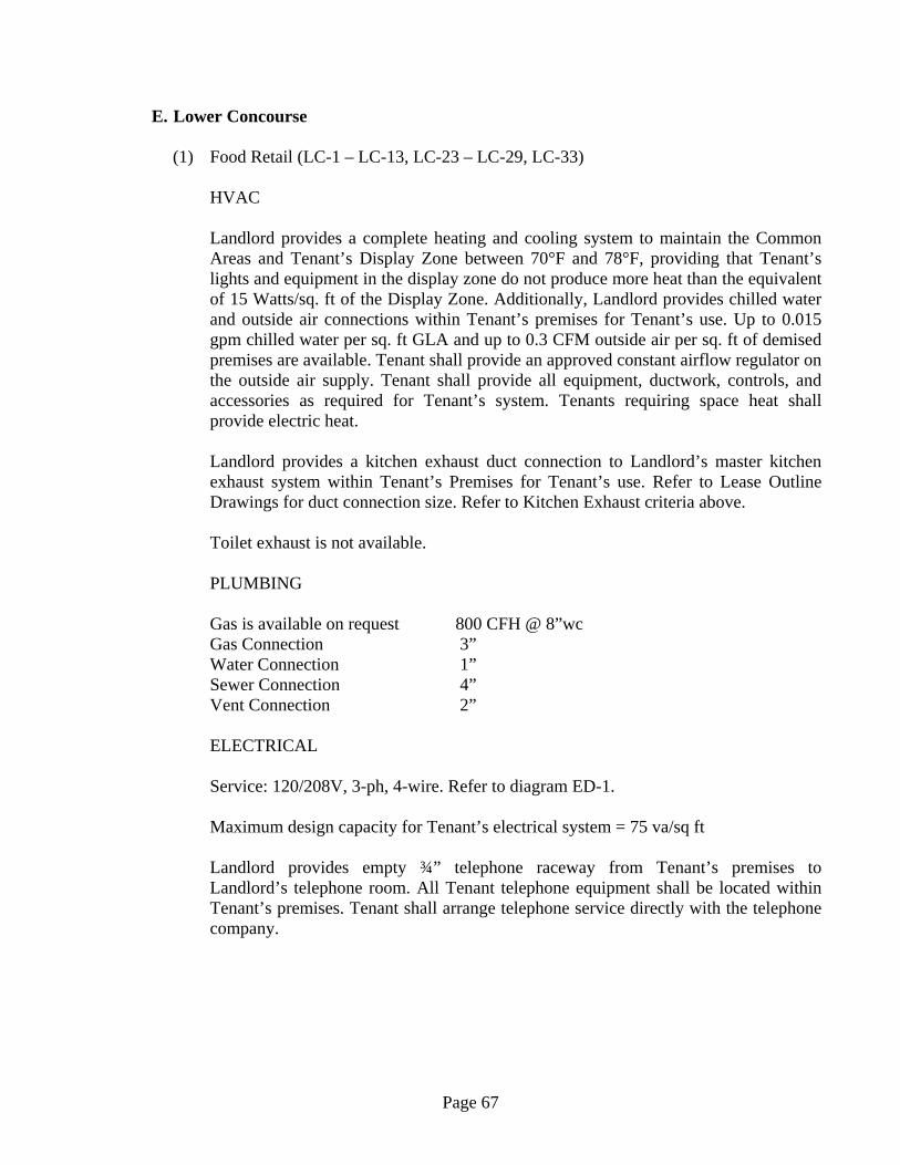
Page 67
E. Lower Concourse (1) Food Retail (LC-1 – LC-13, LC-23 – LC-29, LC-33)
HVAC
Landlord provides a complete heating and cooling system to maintain the Common Areas and Tenant’s Display Zone between 70°F and 78°F, providing that Tenant’s lights and equipment in the display zone do not produce more heat than the equivalent of 15 Watts/sq. ft of the Display Zone. Additionally, Landlord provides chilled water and outside air connections within Tenant’s premises for Tenant’s use. Up to 0.015 gpm chilled water per sq. ft GLA and up to 0.3 CFM outside air per sq. ft of demised premises are available. Tenant shall provide an approved constant airflow regulator on the outside air supply. Tenant shall provide all equipment, ductwork, controls, and accessories as required for Tenant’s system. Tenants requiring space heat shall provide electric heat.
Landlord provides a kitchen exhaust duct connection to Landlord’s master kitchen exhaust system within Tenant’s Premises for Tenant’s use. Refer to Lease Outline Drawings for duct connection size. Refer to Kitchen Exhaust criteria above.
Toilet exhaust is not available.
PLUMBING
Gas is available on request 800 CFH @ 8”wc Gas Connection 3” Water Connection 1” Sewer Connection 4” Vent Connection 2”
ELECTRICAL Service: 120/208V, 3-ph, 4-wire. Refer to diagram ED-1. Maximum design capacity for Tenant’s electrical system = 75 va/sq ft Landlord provides empty ¾” telephone raceway from Tenant’s premises to Landlord’s telephone room. All Tenant telephone equipment shall be located within Tenant’s premises. Tenant shall arrange telephone service directly with the telephone company.
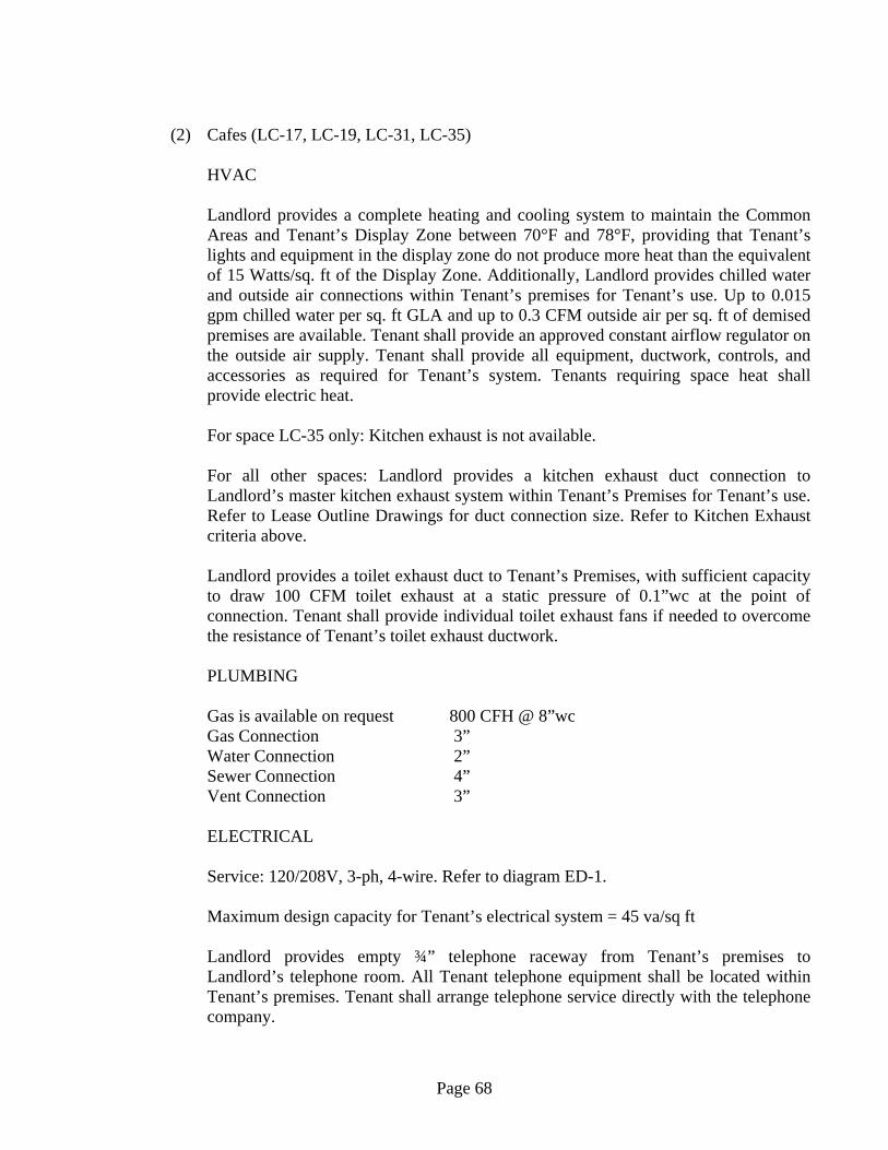
Page 68
(2) Cafes (LC-17, LC-19, LC-31, LC-35)
HVAC
Landlord provides a complete heating and cooling system to maintain the Common Areas and Tenant’s Display Zone between 70°F and 78°F, providing that Tenant’s lights and equipment in the display zone do not produce more heat than the equivalent of 15 Watts/sq. ft of the Display Zone. Additionally, Landlord provides chilled water and outside air connections within Tenant’s premises for Tenant’s use. Up to 0.015 gpm chilled water per sq. ft GLA and up to 0.3 CFM outside air per sq. ft of demised premises are available. Tenant shall provide an approved constant airflow regulator on the outside air supply. Tenant shall provide all equipment, ductwork, controls, and accessories as required for Tenant’s system. Tenants requiring space heat shall provide electric heat.
For space LC-35 only: Kitchen exhaust is not available.
For all other spaces: Landlord provides a kitchen exhaust duct connection to Landlord’s master kitchen exhaust system within Tenant’s Premises for Tenant’s use. Refer to Lease Outline Drawings for duct connection size. Refer to Kitchen Exhaust criteria above.
Landlord provides a toilet exhaust duct to Tenant’s Premises, with sufficient capacity to draw 100 CFM toilet exhaust at a static pressure of 0.1”wc at the point of connection. Tenant shall provide individual toilet exhaust fans if needed to overcome the resistance of Tenant’s toilet exhaust ductwork.
PLUMBING
Gas is available on request 800 CFH @ 8”wc Gas Connection 3” Water Connection 2” Sewer Connection 4” Vent Connection 3”
ELECTRICAL Service: 120/208V, 3-ph, 4-wire. Refer to diagram ED-1. Maximum design capacity for Tenant’s electrical system = 45 va/sq ft Landlord provides empty ¾” telephone raceway from Tenant’s premises to Landlord’s telephone room. All Tenant telephone equipment shall be located within Tenant’s premises. Tenant shall arrange telephone service directly with the telephone company.
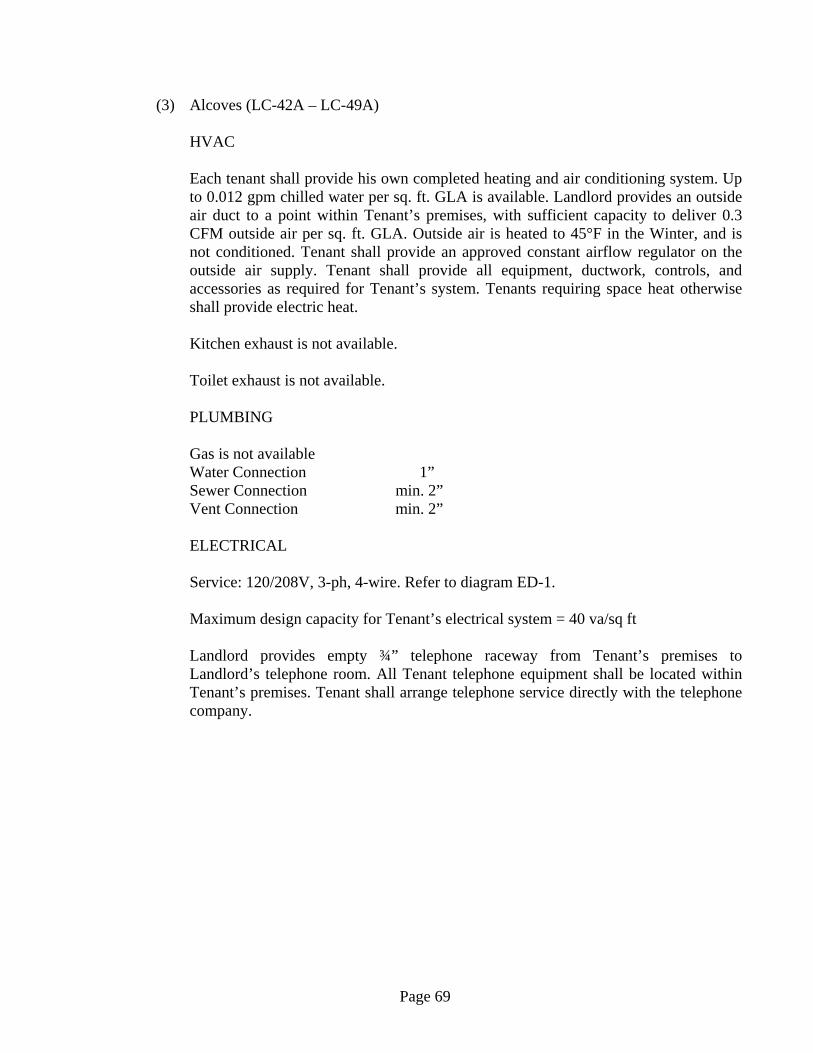
Page 69
(3) Alcoves (LC-42A – LC-49A)
HVAC
Each tenant shall provide his own completed heating and air conditioning system. Up to 0.012 gpm chilled water per sq. ft. GLA is available. Landlord provides an outside air duct to a point within Tenant’s premises, with sufficient capacity to deliver 0.3 CFM outside air per sq. ft. GLA. Outside air is heated to 45°F in the Winter, and is not conditioned. Tenant shall provide an approved constant airflow regulator on the outside air supply. Tenant shall provide all equipment, ductwork, controls, and accessories as required for Tenant’s system. Tenants requiring space heat otherwise shall provide electric heat.
Kitchen exhaust is not available.
Toilet exhaust is not available.
PLUMBING Gas is not available Water Connection 1” Sewer Connection min. 2” Vent Connection min. 2”
ELECTRICAL Service: 120/208V, 3-ph, 4-wire. Refer to diagram ED-1. Maximum design capacity for Tenant’s electrical system = 40 va/sq ft Landlord provides empty ¾” telephone raceway from Tenant’s premises to Landlord’s telephone room. All Tenant telephone equipment shall be located within Tenant’s premises. Tenant shall arrange telephone service directly with the telephone company.
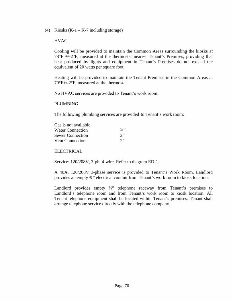
Page 70
(4) Kiosks (K-1 – K-7 including storage)
HVAC
Cooling will be provided to maintain the Common Areas surrounding the kiosks at 78°F +/-2°F, measured at the thermostat nearest Tenant’s Premises, providing that heat produced by lights and equipment in Tenant’s Premises do not exceed the equivalent of 20 watts per square foot.
Heating will be provided to maintain the Tenant Premises in the Common Areas at 70°F+/-2°F, measured at the thermostat.
No HVAC services are provided to Tenant’s work room.
PLUMBING The following plumbing services are provided to Tenant’s work room:
Gas is not available Water Connection ¾” Sewer Connection 2” Vent Connection 2”
ELECTRICAL Service: 120/208V, 3-ph, 4-wire. Refer to diagram ED-1. A 40A, 120/208V 3-phase service is provided to Tenant’s Work Room. Landlord provides an empty ¾” electrical conduit from Tenant’s work room to kiosk location. Landlord provides empty ¾” telephone raceway from Tenant’s premises to Landlord’s telephone room and from Tenant’s work room to kiosk location. All Tenant telephone equipment shall be located within Tenant’s premises. Tenant shall arrange telephone service directly with the telephone company.
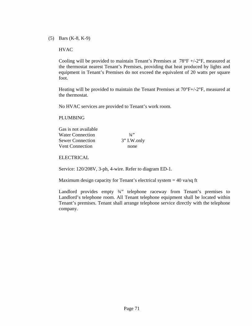
Page 71
(5) Bars (K-8, K-9)
HVAC
Cooling will be provided to maintain Tenant’s Premises at 78°F +/-2°F, measured at the thermostat nearest Tenant’s Premises, providing that heat produced by lights and equipment in Tenant’s Premises do not exceed the equivalent of 20 watts per square foot.
Heating will be provided to maintain the Tenant Premises at 70°F+/-2°F, measured at the thermostat.
No HVAC services are provided to Tenant’s work room.
PLUMBING
Gas is not available Water Connection ¾” Sewer Connection 3” I.W.only Vent Connection none
ELECTRICAL
Service: 120/208V, 3-ph, 4-wire. Refer to diagram ED-1.
Maximum design capacity for Tenant’s electrical system = 40 va/sq ft
Landlord provides empty ¾” telephone raceway from Tenant’s premises to Landlord’s telephone room. All Tenant telephone equipment shall be located within Tenant’s premises. Tenant shall arrange telephone service directly with the telephone company.
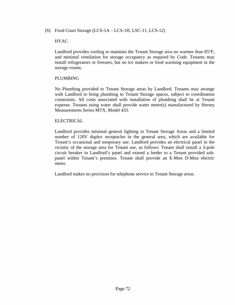
Page 72
(6) Food Court Storage (LCS-1A – LCS-1H, LSC-11, LCS-12)
HVAC
Landlord provides cooling to maintain the Tenant Storage area no warmer than 85°F, and minimal ventilation for storage occupancy as required by Code. Tenants may install refrigerators or freezers, but no ice makers or food warming equipment in the storage rooms.
PLUMBING
No Plumbing provided to Tenant Storage areas by Landlord. Tenants may arrange with Landlord to bring plumbing to Tenant Storage spaces, subject to coordination constraints. All costs associated with installation of plumbing shall be at Tenant expense. Tenants using water shall provide water meter(s) manufactured by Hersey Measurements Series MTX, Model 433.
ELECTRICAL
Landlord provides minimal general lighting in Tenant Storage Areas and a limited number of 120V duplex receptacles in the general area, which are available for Tenant’s occasional and temporary use. Landlord provides an electrical panel in the vicinity of the storage area for Tenant use, as follows: Tenant shall install a 3-pole circuit breaker in Landlord’s panel and extend a feeder to a Tenant provided sub-panel within Tenant’s premises. Tenant shall provide an E-Mon D-Mon electric meter.
Landlord makes no provision for telephone service to Tenant Storage areas.
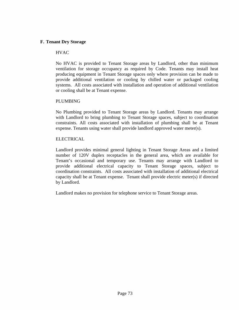
Page 73
F. Tenant Dry Storage
HVAC
No HVAC is provided to Tenant Storage areas by Landlord, other than minimum ventilation for storage occupancy as required by Code. Tenants may install heat producing equipment in Tenant Storage spaces only where provision can be made to provide additional ventilation or cooling by chilled water or packaged cooling systems. All costs associated with installation and operation of additional ventilation or cooling shall be at Tenant expense.
PLUMBING
No Plumbing provided to Tenant Storage areas by Landlord. Tenants may arrange with Landlord to bring plumbing to Tenant Storage spaces, subject to coordination constraints. All costs associated with installation of plumbing shall be at Tenant expense. Tenants using water shall provide landlord approved water meter(s).
ELECTRICAL
Landlord provides minimal general lighting in Tenant Storage Areas and a limited number of 120V duplex receptacles in the general area, which are available for Tenant’s occasional and temporary use. Tenants may arrange with Landlord to provide additional electrical capacity to Tenant Storage spaces, subject to coordination constraints. All costs associated with installation of additional electrical capacity shall be at Tenant expense. Tenant shall provide electric meter(s) if directed by Landlord.
Landlord makes no provision for telephone service to Tenant Storage areas.

Page 74
VI. TENANT SUBMISSION FORMS AND SCHEDULES
1. Tenant Electrical Data Form 2. Electrical Panelboard Schedule
3. Mechanical Equipment Schedule
4. Tenant Sprinkler Design Basis Form
5. MEP Review Checklist Form
6. Allowable Pipe Material for Various Systems Pipe Sizes 4”, 125 psi Maximum Working
Pressure
7. Allowable Piping Material for Tenant Steam Systems
8. Allowable Piping Material for Tenant Chilled Water Systems

Page 75

Page 76
CONNECTED KVA
SIZING FACTOR*
FEEDER KVA
General Loads
Lighting 125%
Sign 125%
Receptacles See NEC 220-3(c) (5)
Water Heater See NEC 220-20
@ Kitchen Equipment See NEC 220-20
@ Miscellaneous Appliances See NEC 220-20
HVAC Loads
Fans 125%
+ A/C Compressors
+ Duct Heating Coils
Other Heat (unit heaters, baseboard heat, etc.) 125%
TOTALS
* Feeder sizing factor per NEC 220-10(b), NEC 220-20, etc.@ Provide an equipment list showing each piece of equipment and its nameplate electrical data.+ Larger of coincident loads at 125%, other at 0%
Largest Motor is _____ HP ____ phase
Service Size Calculation
Feeder Amps = Feeder = __________ = _______ Amps1.732 x kV 1.732 x _____
(Note "kV" = 0.208 or 0.480)
Requested Service: ________Amps Minimum Wire Size: _________
Prepared by: ____________________________ Signature ___________________________
Firm: __________________________________ Telephone: _________________________
For Landlord Use:
Approved Service Size: ________ Amps Service: _____________________
LOAD ITEM
Tenant _______________________________ Space_____________________ GLA____________
TENANT ELECTRICAL DATA
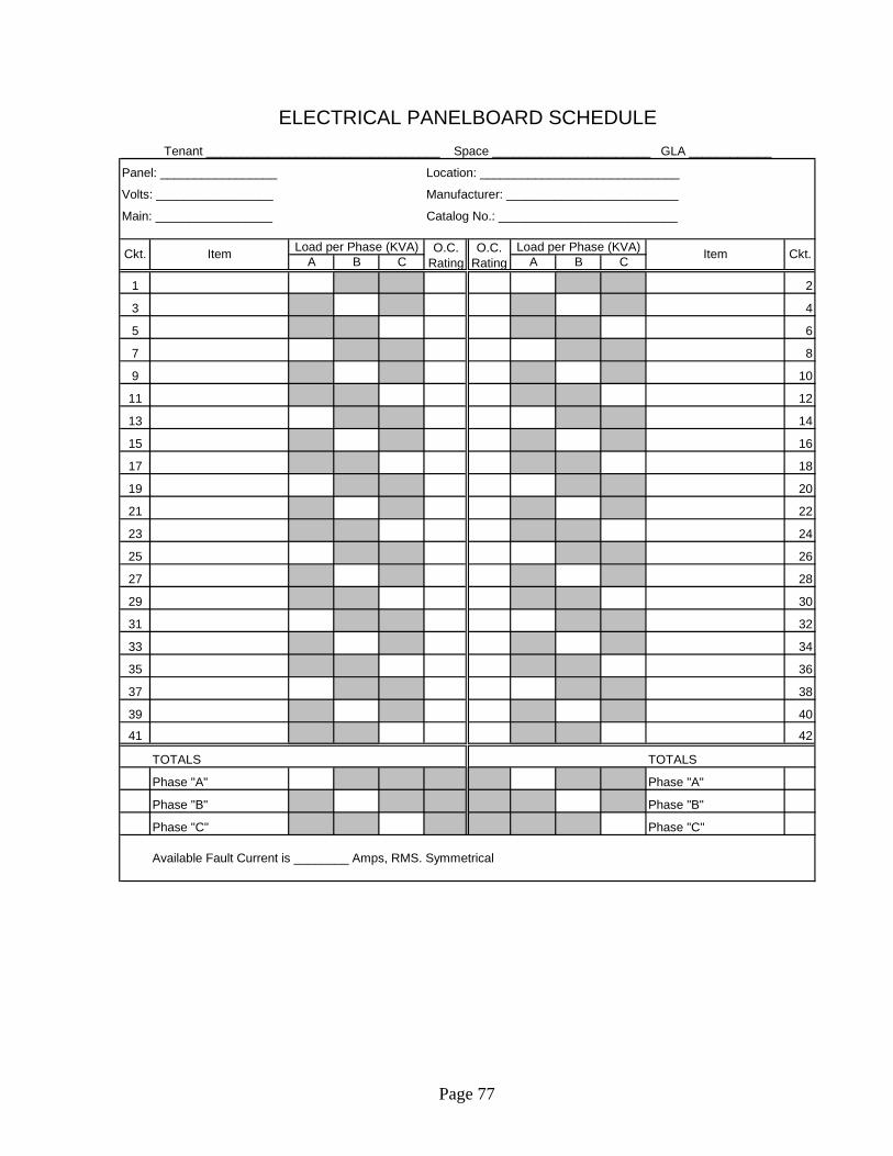
Page 77
Panel: _________________ Location: _____________________________
Volts: _________________ Manufacturer: _________________________
Main: _________________ Catalog No.: __________________________
A B C A B C
1 2
3 4
5 6
7 8
9 10
11 12
13 14
15 16
17 18
19 20
21 22
23 24
25 26
27 28
29 30
31 32
33 34
35 36
37 38
39 40
41 42
TOTALS TOTALS
Phase "A" Phase "A"
Phase "B" Phase "B"
Phase "C" Phase "C"
Available Fault Current is ________ Amps, RMS. Symmetrical
O.C. Rating
O.C. Rating
ELECTRICAL PANELBOARD SCHEDULE
Tenant __________________________________ Space _______________________ GLA ____________
Load per Phase (KVA) Load per Phase (KVA)Item ItemCkt. Ckt.

Page 78
Unit Tag #
Serves
Fan Total CFM (e.g. Supply Air)
Outside Air CFM
Total Cooling Btuh
Sensible Cooling Btuh
Chilled Water GPM
Chilled Water Pressure Drop (ft)
Entering Chilled Water Temperature (F) 45F 45F 45F 45F
Leaving Chilled Water Temperature (F)
Heating Btuh
Electric Coil kW (if applicable)
Steam lbs/hr (if applicable)
Steam Supply Pressure (psi)
Voltage/Phase
Supply Fan FLA
Manufacturer
Model
TENANT HVAC EQUIPMENT SCHEDULETO BE COMPLETED BY TENANT'S ENGINEER
Tenant __________________________ Space ____________ GLA __________
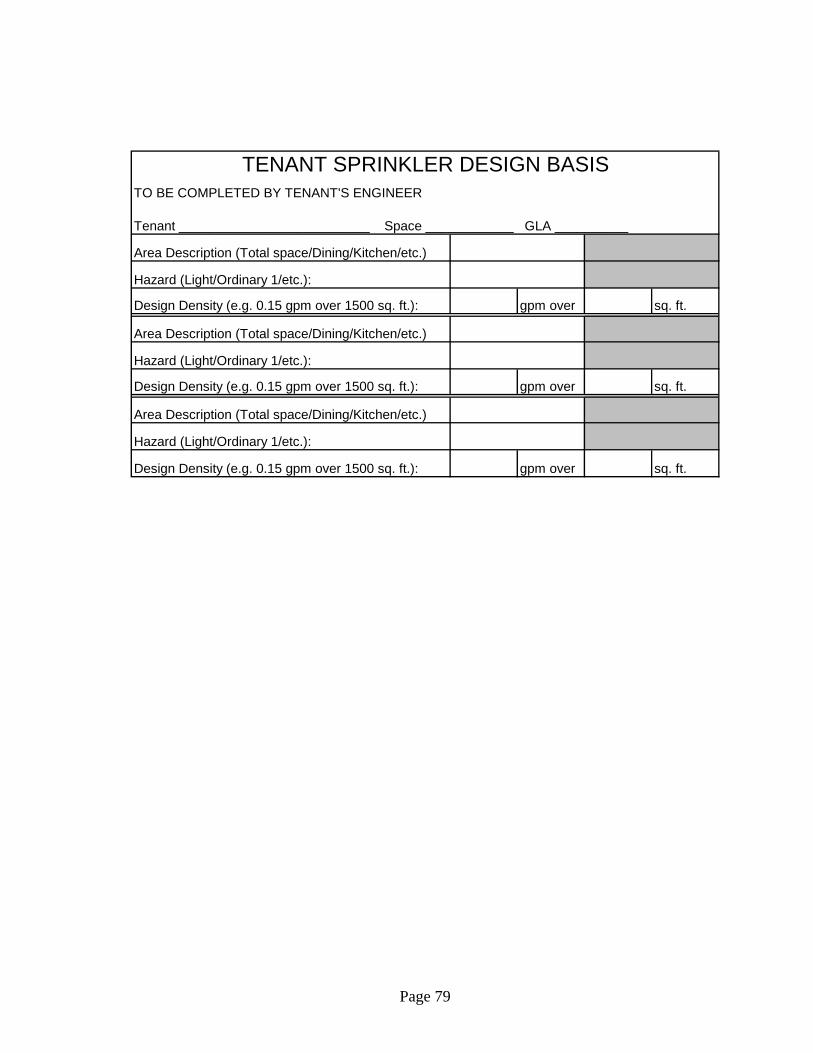
Page 79
Area Description (Total space/Dining/Kitchen/etc.)
Hazard (Light/Ordinary 1/etc.):
Design Density (e.g. 0.15 gpm over 1500 sq. ft.): gpm over sq. ft.
Area Description (Total space/Dining/Kitchen/etc.)
Hazard (Light/Ordinary 1/etc.):
Design Density (e.g. 0.15 gpm over 1500 sq. ft.): gpm over sq. ft.
Area Description (Total space/Dining/Kitchen/etc.)
Hazard (Light/Ordinary 1/etc.):
Design Density (e.g. 0.15 gpm over 1500 sq. ft.): gpm over sq. ft.
TENANT SPRINKLER DESIGN BASISTO BE COMPLETED BY TENANT'S ENGINEER
Tenant __________________________ Space ____________ GLA __________
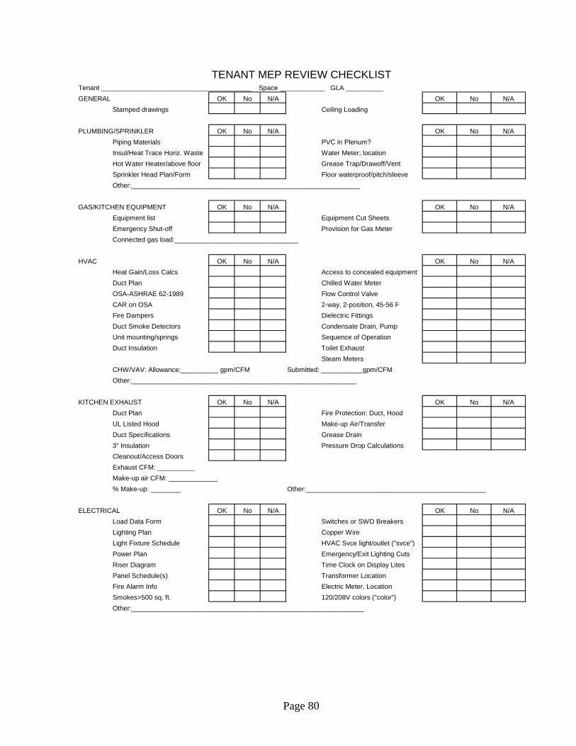
Page 80
GENERAL OK No N/A OK No N/A
Stamped drawings Ceiling Loading
PLUMBING/SPRINKLER OK No N/A OK No N/A
Piping Materials PVC in Plenum?
Insul/Heat Trace Horiz. Waste Water Meter; location
Hot Water Heater/above floor Grease Trap/Drawoff/Vent
Sprinkler Head Plan/Form Floor waterproof/pitch/sleeve
Other:_____________________________________________________________
GAS/KITCHEN EQUIPMENT OK No N/A OK No N/A
Equipment list Equipment Cut Sheets
Emergency Shut-off Provision for Gas Meter
Connected gas load:_________________________________
HVAC OK No N/A OK No N/A
Heat Gain/Loss Calcs Access to concealed equipment
Duct Plan Chilled Water Meter
OSA-ASHRAE 62-1989 Flow Control Valve
CAR on OSA 2-way, 2-position, 45-56 F
Fire Dampers Dielectric Fittings
Duct Smoke Detectors Condensate Drain, Pump
Unit mounting/springs Sequence of Operation
Duct Insulation Toilet Exhaust
Steam Meters
CHW/VAV: Allowance:__________ gpm/CFM Submitted: ___________gpm/CFM
Other:____________________________________________________________
KITCHEN EXHAUST OK No N/A OK No N/A
Duct Plan Fire Protection: Duct, Hood
UL Listed Hood Make-up Air/Transfer
Duct Specifications Grease Drain
3" Insulation Pressure Drop Calculations
Cleanout/Access Doors
Exhaust CFM: __________
Make-up air CFM: _____________
% Make-up: ________ Other:________________________________________________
ELECTRICAL OK No N/A OK No N/A
Load Data Form Switches or SWD Breakers
Lighting Plan Copper Wire
Light Fixture Schedule HVAC Svce light/outlet ("svce")
Power Plan Emergency/Exit Lighting Cuts
Riser Diagram Time Clock on Display Lites
Panel Schedule(s) Transformer Location
Fire Alarm Info Electric Meter, Location
Smokes>500 sq. ft. 120/208V colors ("color")
Other:______________________________________________________________
TENANT MEP REVIEW CHECKLISTTenant ________________________________________ Space ____________ GLA __________
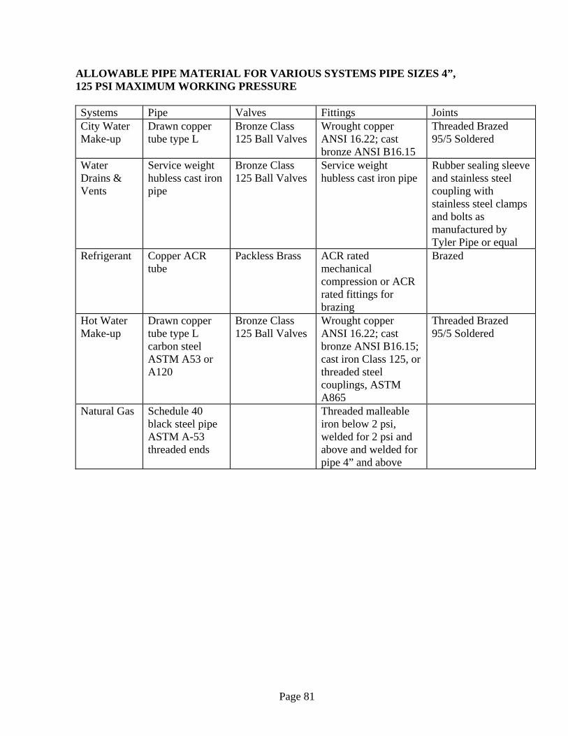
Page 81
ALLOWABLE PIPE MATERIAL FOR VARIOUS SYSTEMS PIPE SIZES 4”, 125 PSI MAXIMUM WORKING PRESSURE Systems Pipe Valves Fittings Joints City Water Make-up
Drawn copper tube type L
Bronze Class 125 Ball Valves
Wrought copper ANSI 16.22; cast bronze ANSI B16.15
Threaded Brazed 95/5 Soldered
Water Drains & Vents
Service weight hubless cast iron pipe
Bronze Class 125 Ball Valves
Service weight hubless cast iron pipe
Rubber sealing sleeve and stainless steel coupling with stainless steel clamps and bolts as manufactured by Tyler Pipe or equal
Refrigerant Copper ACR tube
Packless Brass ACR rated mechanical compression or ACR rated fittings for brazing
Brazed
Hot Water Make-up
Drawn copper tube type L carbon steel ASTM A53 or A120
Bronze Class 125 Ball Valves
Wrought copper ANSI 16.22; cast bronze ANSI B16.15; cast iron Class 125, or threaded steel couplings, ASTM A865
Threaded Brazed 95/5 Soldered
Natural Gas Schedule 40 black steel pipe ASTM A-53 threaded ends
Threaded malleable iron below 2 psi, welded for 2 psi and above and welded for pipe 4” and above

Page 82
ALLOWABLE PIPING MATERIAL FOR TENANT STEAM SYSTEMS Service Pressure Pipe Sizes up to 4”
Steam up to 15 psi
Piping: Carbon steel - Threaded schedule 40 seamless ASTM A120 or ASTM A53 Fittings: Threaded - steel couplings ASTM A 865 malleable iron Class 150 ANSI 16.3, cast iron Class 125 ANSI 16.4 Valves: Threaded - cast iron Class 125 ASTM A126 ductile iron Class 150 ASTM A395, malleable iron Class 150 ASTM A 197
Low Pressure Steam Condensate
Piping: Carbon steel - Threaded schedule 80 seamless ASTM A120 or ASTM A53 Fittings: Threaded - steel couplings ASTM A 865 malleable iron Class 150 ANSI 16.3, cast iron Class 125 ANSI 16.4 Valves: Threaded - cast iron Class 125 ASTM A126 ductile iron Class 150 ASTM A395, malleable iron Class 150 ASTM A 197
Steam above 15 psi
Not applicable
High Pressure Steam Condensate
Not applicable
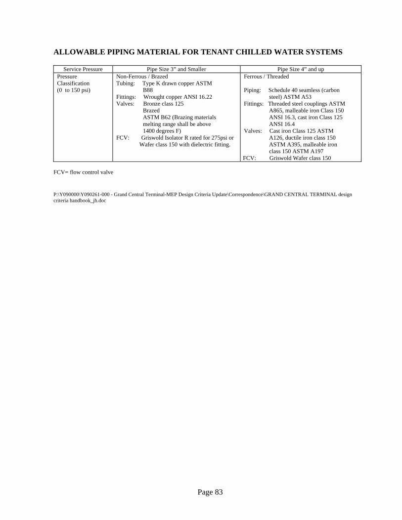
Page 83
ALLOWABLE PIPING MATERIAL FOR TENANT CHILLED WATER SYSTEMS
Service Pressure Pipe Size 3” and Smaller Pipe Size 4” and up Pressure Classification (0 to 150 psi)
Non-Ferrous / Brazed Tubing: Type K drawn copper ASTM B88 Fittings: Wrought copper ANSI 16.22 Valves: Bronze class 125 Brazed ASTM B62 (Brazing materials melting range shall be above 1400 degrees F) FCV: Griswold Isolator R rated for 275psi or
Wafer class 150 with dielectric fitting.
Ferrous / Threaded Piping: Schedule 40 seamless (carbon steel) ASTM A53 Fittings: Threaded steel couplings ASTM A865, malleable iron Class 150 ANSI 16.3, cast iron Class 125 ANSI 16.4 Valves: Cast iron Class 125 ASTM A126, ductile iron class 150 ASTM A395, malleable iron class 150 ASTM A197 FCV: Griswold Wafer class 150
FCV= flow control valve
P:\Y090000\Y090261-000 - Grand Central Terminal-MEP Design Criteria Update\Correspondence\GRAND CENTRAL TERMINAL design criteria handbook_jh.doc