grade descriptions - homepage – general...
TRANSCRIPT

� GRADE DESCRIPTIONSPAGE 86
� CARBIDE SELECTION GUIDEPAGE 87
� WORKPIECE MATERIAL DATAPAGE 88
� GUIDELINESPAGE 91
� DR SOLID CARBIDE GUIDELINESPAGE 94
� GUIDELINESPAGE 95

� CHAMFER RINGSPAGE 100
� SLIP-FITPAGE 102
� GUIDELINESPAGE 103
� GUIDELINESPAGE 109
� GUIDELINESPAGE 111
1286
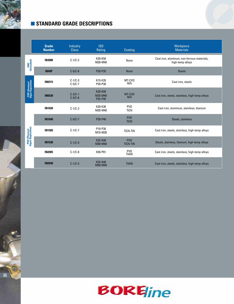
� STANDARD GRADE DESCRIPTIONSU
NC
(Unc
oate
d)CV
D (C
hem
ical
Vapo
r Dep
ositi
on)
PVD
(Phy
sica
lVa
por D
epos
ition
)
Grade Industry ISO WorkpieceNumber Class Rating Coating Materials
IN30M C-1/C-2 K20-K50None
Cast iron, aluminum, non-ferrous materials,M20-M40 high-temp alloys
IN40P C-5/C-6 P20-P35 None Steels
IN6515 C-1/C-3 K15-K35 MT-CVD Cast iron, steelsC-5/C-7 P20-P30 Al2O3
C-2/C-1K20-K50
MT-CVD ,IN6530 M25-M40 Cast iron, steels, stainless, high-temp alloysC-5/C-6 P25-P45
Al2O3
IN1030 C-1/C-2K20-K30 PVD Cast iron, aluminum, stainless, titanium
M20-M40 TiCN
IN1040 C-5/C-7 P20-P40 PVD Steels, stainlessTiCN
IN1505 C-1/C-7 P10-P30 Cast iron, steels, stainless, high-temp alloysM10-M30 TiCN-TiN
IN1530 C-1/C-5K25-K40 PVD
Steels, stainless, titanium, high-temp alloysM30-M40 TiCN-TiN
IN2005 C-1/C-8 K50-P01 PVD Cast iron, steels, stainless, high-temp alloysTiAlN
IN2030 C-1/C-5 K25-K40 Cast iron, steels, stainless, high-temp alloysM30-M40 TiAIN

1387
� CARBIDE SELECTION GUIDE
Grade
Material
Directionof
Use
Wear Resistance
Toughness Toughness Toughness
Wear ResistanceWear Resistance
Increase Speed
Increase Feed Increase Feed Increase Feed
Increase Speed Increase Speed
C1 C2 C3 C4
K50 K45 K40 K35 K30 K25 K20 K15 K10 K05 K01
Short Chipping Malleable Iron, Non-Ferrous Metal,Hardened Iron, Chilled Iron, Cast Iron
Free Cutting Steels, Malleable Iron, Steel Casting, Steel
C5 C6 C7 C8
P50 P45 P40 P35 P30 P25 P20 P15 P10 P05 P01
High-Temp Alloys, AlloyIron, Steel Casting,
Manganese
M50 M40 M30 M20 M10Coat
ing
IN30M
IN40P
IN6515
IN6530
IN1030
IN1040
IN1505
IN1530
IN2005
IN2030
IN40P
IN6515 IN6515
IN6530
IN1505
IN6530
IN1030
IN1505
IN1040
IN1530IN1530
IN1030
IN30M
IN6530
IN30M
PVD
C
VD
U
ncoa
ted
IN2005
IN2030
IN2005
IN2030 IN2030
IN2005
88
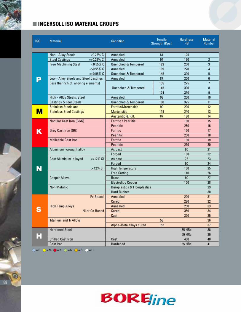
(CONT.)ISO Material Condition Tensile Hardness Material
Strength (Kpsi) HB Number
Non - Alloy Steels <0.25% C Annealed 61 125 1 Steel Castings =>0.25% C Annealed 94 190 2Free Machining Steel <0.55% C Quenched & Tempered 123 250 3
=>0.55% C Annealed 109 220 4=>0.55% C Quenched & Tempered 145 300 5
Low - Alloy Steels and Steel Castings Annealed 87 200 6(less than 5% of alloying elements) 135 275 7
Quenched & Tempered 145 300 8174 350 9
High - Alloy Steels, Steel Annealed 99 200 10Castings & Tool Steels Quenched & Tempered 160 325 11Stainless Steels and Ferritic/Martensitic 99 200 12Stainless Steel Castings Martensitic 119 240 13
Austenitic & P.H. 87 180 14Nodular Cast Iron (GGG) Ferritic / Pearlitic 180 15
Pearlitic 260 16Grey Cast Iron (GG) Ferritic 160 17
Pearlitic 250 18Malleable Cast Iron Ferritic 130 19
Pearlitic 230 20Aluminum wrought alloy As cast 60 21
Forged 100 22Cast Aluminum alloyed <=12% Si As cast 75 23
Forged 90 24> 12% Si High Temperature 130 25
Free Cutting 110 26Copper Alloys Brass 90 27
Electrolitic Copper 100 28Non Metallic Duroplastics & Fiberplastics 29
Hard Rubber 30Fe Based Annealed 200 31
Cured 280 32High Temp Alloys Annealed 250 33
Ni or Co Based Cured 350 34Cast 320 35
Titanium and Ti Alloys 58 36Alpha+Beta alloys cured 152 37
Hardened Steel 55 HRc 3860 HRc 39
Chilled Cast Iron Cast 400 40Cast Iron Hardened 55 HRc 41
P
M
K
N
S
H
� INGERSOLL ISO MATERIAL GROUPS
= P =M = K = N = S = H
89
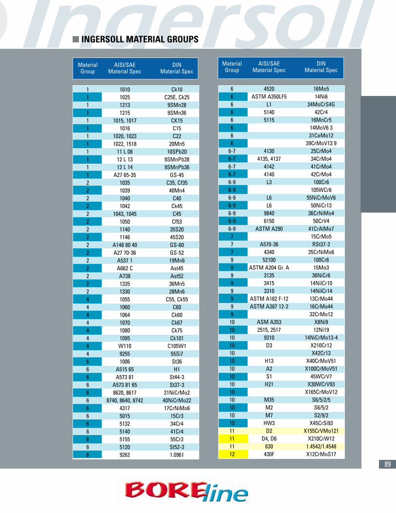
Material AISI/SAE DINGroup Material Spec Material Spec
1 1010 Ck101 1025 C25E, Ck251 1213 9SMn281 1215 9SMn361 1015, 1017 CK151 1016 C151 1020, 1023 C221 1022, 1518 20Mn51 11 L 08 10SPb201 12 L 13 9SMnPb281 12 L 14 9SMnPb361 A27 65-35 GS-452 1035 C35, Cf352 1039 40Mn42 1040 C402 1042 Ck452 1043, 1045 C452 1050 Cf532 1140 35S202 1146 45S202 A148 80 40 GS-602 A27 70-36 GS-522 A537 1 19Mn62 A662 C Ast452 A738 Ast522 1335 36Mn52 1330 28Mn64 1055 C55, Ck554 1060 C604 1064 Ck604 1070 Ck674 1080 Ck754 1095 Ck1014 W110 C105W14 9255 55Si76 1006 St366 A515 65 H16 A573 81 St44-36 A573 81 65 St37-36 8620, 8617 21NiCrMo26 8740, 8640, 8742 40NiCrMo226 4317 17CrNiMo66 5015 15Cr36 5132 34Cr46 5140 41Cr46 5155 55Cr36 5120 St52-36 9262 1.0961
Material AISI/SAE DINGroup Material Spec Material Spec
6 4520 16Mo56 ASTM A350LF5 14Ni66 L1 34MoCrS4G6 5140 42Cr46 5115 16MnCr56 14MoV6 36 31CeMo126 39CrMoV13 9
6-7 4130 25CrMo46-7 4135, 4137 34CrMo46-7 4142 41CrMo46-7 4140 42CrMo46-9 L3 100Cr66-9 105WCr66-9 L6 55NiCrMoV66-9 L6 50NiCr136-9 9840 36CrNiMo46-9 6150 50CrV46-9 ASTM A290 41CrAlMo77 15CrMo57 A570-36 RSt37-27 4340 35CrNiMo69 52100 100Cr69 ASTM A204 Gr. A 15Mo39 3135 36NiCr69 3415 14NilCr109 3310 14NilCr149 ASTM A182 F-12 13CrMo449 ASTM A387 12-2 16CrMo449 32CrMo1210 ASM A353 X8Ni910 2515, 2517 12Ni1910 9310 14NiCrMo13-410 D3 X210Cr1210 X42Cr1310 H13 X40CrMoV5110 A2 X100CrMoV5110 S1 45WCrV710 H21 X30WCrV9310 X165CrMoV1210 M35 S6/5/2/510 M2 S6/5/210 M7 S2/9/210 HW3 X45CrSi9311 D2 X155CrVMo12111 D4, D6 X210CrW1211 630 1.4542/1.454812 430F X12CrMoS17
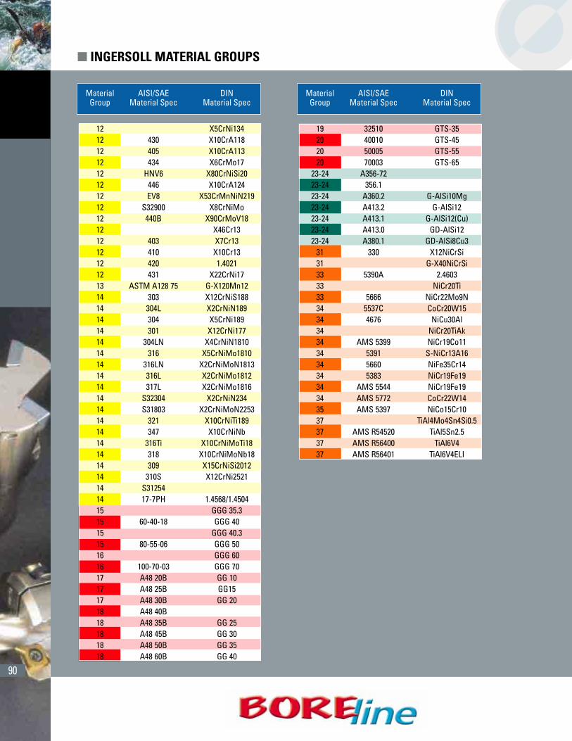
� INGERSOLL MATERIAL GROUPS
90
Material AISI/SAE DINGroup Material Spec Material Spec
12 X5CrNi13412 430 X10CrA11812 405 X10CrA11312 434 X6CrMo1712 HNV6 X80CrNiSi2012 446 X10CrA12412 EV8 X53CrMnNiN21912 S32900 X8CrNiMo12 440B X90CrMoV1812 X46Cr1312 403 X7Cr1312 410 X10Cr1312 420 1.402112 431 X22CrNi1713 ASTM A128 75 G-X120Mn1214 303 X12CrNiS18814 304L X2CrNiN18914 304 X5CrNi18914 301 X12CrNi17714 304LN X4CrNiN181014 316 X5CrNiMo181014 316LN X2CrNiMoN181314 316L X2CrNiMo181214 317L X2CrNiMo181614 S32304 X2CrNiN23414 S31803 X2CrNiMoN225314 321 X10CrNiTi18914 347 X10CrNiNb14 316Ti X10CrNiMoTi1814 318 X10CrNiMoNb1814 309 X15CrNiSi201214 310S X12CrNi252114 S3125414 17-7PH 1.4568/1.450415 GGG 35.315 60-40-18 GGG 4015 GGG 40.315 80-55-06 GGG 5016 GGG 6016 100-70-03 GGG 7017 A48 20B GG 1017 A48 25B GG1517 A48 30B GG 2018 A48 40B18 A48 35B GG 2518 A48 45B GG 3018 A48 50B GG 3518 A48 60B GG 40
Material AISI/SAE DINGroup Material Spec Material Spec
19 32510 GTS-3520 40010 GTS-4520 50005 GTS-5520 70003 GTS-65
23-24 A356-7223-24 356.123-24 A360.2 G-AlSi10Mg23-24 A413.2 G-AlSi1223-24 A413.1 G-AlSi12(Cu)23-24 A413.0 GD-AlSi1223-24 A380.1 GD-AlSi8Cu3
31 330 X12NiCrSi31 G-X40NiCrSi33 5390A 2.460333 NiCr20Ti33 5666 NiCr22Mo9N34 5537C CoCr20W1534 4676 NiCu30Al34 NiCr20TiAk34 AMS 5399 NiCr19Co1134 5391 S-NiCr13A1634 5660 NiFe35Cr1434 5383 NiCr19Fe1934 AMS 5544 NiCr19Fe1934 AMS 5772 CoCr22W1435 AMS 5397 NiCo15Cr1037 TiAl4Mo4Sn4Si0.537 AMS R54520 TiAl5Sn2.537 AMS R56400 TiAl6V437 AMS R56401 TiAl6V4ELI
� INGERSOLL MATERIAL GROUPS

91
1 450 - 550 .001" - .003"2 450 - 550 .001" - .003"3 450 - 550 .001" - .003"4 450 - 550 .001" - .003"5 450 - 550 .001" - .003"6 450 - 550 .001" - .003"7 450 - 550 .001" - .003"8 450 - 550 .001" - .003"9 450 - 550 .001" - .003"
10 450 - 550 .001" - .003"11 450 - 550 .001" - .003"12 400 - 500 .001" - .003"13 300 - 400 .001" - .003"14 400 - 500 .001" - .003"15 300 - 400 .002" - .004"16 300 - 400 .002" - .004"17 450 - 550 .002" - .004"18 450 - 550 .002" - .004"19 450 - 550 .002" - .004"20 450 - 550 .002" - .004"21 1500 - 3000 .002" - .004"22 1500 - 3000 .002" - .004"23 1500 - 3000 .002" - .004"24 1500 - 3000 .002" - .004"25 1500 - 3000 .002" - .004"26 1500 - 3000 .002" - .004"27 1500 - 3000 .002" - .004"28 1500 - 3000 .002" - .004"293031 100 - 200 .001" - .003"32 100 - 200 .001" - .003"33 100 - 200 .001" - .003"34 100 - 200 .001" - .003"35 100 - 200 .001" - .003"36 130 - 230 .001" - .003"37 130 - 230 .001" - .003"38 50 - 100 .001" - .003"39 50 - 100 .001" - .003"40 50 - 100 .001" - .003"41 50 - 100 .001" - .003"
P
M
K
N
S
H
Material Cutting Feed (in./rev.)ISO Number Speed ø.189-ø.292
(SFM)
1 260 - 430 .006" - .010"2 260 - 430 .006" - .010"3 230 - 390 .006" - .010"4 230 - 390 .006" - .010"5 230 - 390 .006" - .010"6 130 - 430 .006" - .010"7 130 - 430 .006" - .010"8 130 - 430 .006" - .010"9 130 - 430 .006" - .010"10 130 - 260 .005" - .008"11 130 - 260 .005" - .008"12 70 - 160 .004" - .006"13 70 - 160 .004" - .006"14 70 - 160 .004" - .006"15 260 - 460 .010" - .014"16 260 - 460 .010" - .014"17 300 - 590 .010" - .014"18 300 - 590 .010" - .014"19 300 - 590 .010" - .014"20 300 - 590 .010" - .014"21 260 - 520 .010" - .014"22 260 - 520 .010" - .014"23 260 - 520 .010" - .014"24 260 - 520 .010" - .014"25 260 - 520 .010" - .014"26 260 - 520 .010" - .014"27 260 - 520 .010" - .014"28 260 - 520 .010" - .014"293031 70 - 160 .003" - .005"32 70 - 160 .003" - .005"33 70 - 160 .003" - .005"34 70 - 160 .003" - .005"35 70 - 160 .003" - .005"36 70 - 160 .004" - .006"37 70 - 160 .004" - .006"38 70 - 160 .004" - .006"39 70 - 160 .004" - .006"40 70 - 160 .004" - .006"41 70 - 160 .004" - .006"
P
M
K
N
S
H
Material Cutting Feed (in./rev.)ISO Number Speed ø.189-ø.292
(SFM)
� OPERATING GUIDELINES- SERIES FAK AND SERIES Y
SERIES “FAK” DRILL SERIES “Y” (SPOT IN) DRILL
= P =M = K = N = S = H
92
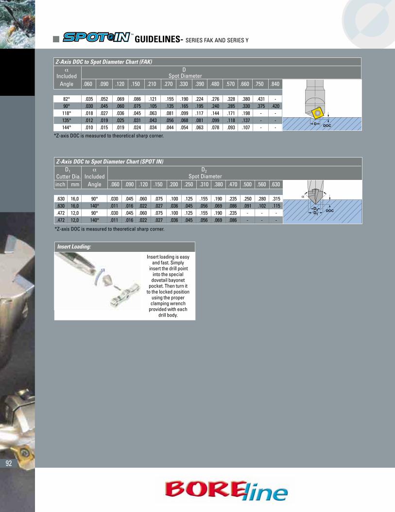
*Z-axis DOC is measured to theoretical sharp corner.
� DIncluded Spot Diameter
Angle .060 .090 .120 .150 .210 .270 .330 .390 .480 .570 .660 .750 .840
82° .035 .052 .069 .086 .121 .155 .190 .224 .276 .328 .380 .431 -90° .030 .045 .060 .075 .105 .135 .165 .195 .240 .285 .330 .375 .420118° .018 .027 .036 .045 .063 .081 .099 .117 .144 .171 .198 - -135° .012 .019 .025 .031 .043 .056 .068 .081 .099 .118 .137 - -144° .010 .015 .019 .024 .034 .044 .054 .063 .078 .093 .107 - -
Z-Axis DOC to Spot Diameter Chart (FAK)
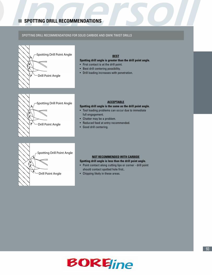
Insert loading is easyand fast. Simply
insert the drill pointinto the special
dovetail bayonetpocket. Then turn it
to the locked positionusing the properclamping wrench
provided with eachdrill body.
*Z-axis DOC is measured to theoretical sharp corner.
Z-Axis DOC to Spot Diameter Chart (SPOT IN)D1 � D2
Cutter Dia. Included Spot Diameterinch mm Angle .060 .090 .120 .150 .200 .250 .310 .380 .470 .500 .560 .630
.630 16,0 90° .030 .045 .060 .075 .100 .125 .155 .190 .235 .250 .280 .315
.630 16,0 140° .011 .016 .022 .027 .036 .045 .056 .069 .086 .091 .102 .115
.472 12,0 90° .030 .045 .060 .075 .100 .125 .155 .190 .235 - - -
.472 12,0 140° .011 .016 .022 .027 .036 .045 .056 .069 .086 - - -
Insert Loading:
� GUIDELINES- SERIES FAK AND SERIES Y
93
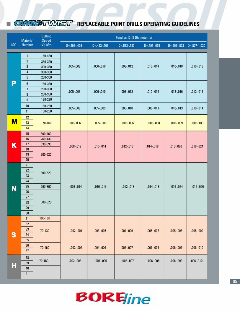
SPOTTING DRILL RECOMMENDATIONS FOR SOLID CARBIDE AND QWIK TWIST DRILLS
Spotting Drill Point Angle
Drill Point Angle
Spotting Drill Point Angle
Drill Point Angle
ACCEPTABLESpotting drill angle is the same as the drill point angle.• Tool loading problems can occur due to immediate
full engagement.• Chatter may be a problem.• Reduced feed at entry recommended.• Good drill centering.
BESTSpotting drill angle is greater than the drill point angle.• First contact is at the drill point.• Best drill centering possibility.• Drill loading increases with penetration.
Spotting Drill Point Angle
Drill Point Angle
NOT RECOMMENDED WITH CARBIDESpotting drill angle is less than the drill point angle.• Point contact along cutting lips or corner - drill point
should contact spotted hole first..• Chipping likely in these areas.
� SPOTTING DRILL RECOMMENDATIONS

94
(CONT.)
� DR SOLID CARBIDE DRILLS OPERATING GUIDELINES
P
M
K
N
S
H
Material Cutting Feed (in/rev) Feed (in/rev) Feed (in/rev) Feed (in/rev)ISO Number Speed (SFM) ø.118 - ø.185 ø.189 - ø.292 ø.295 - ø.396 ø.397 - ø.500
1 250 - 450 .002" - .006" .003" - .007" .005" - .010" .006" - .012"2 250 - 450 .002" - .006" .003" - .007" .005" - .010" .006" - .012"3 150 - 400 .002" - .004" .003" - .005" .005" - .008" .006" - .010"4 150 - 400 .002" - .004" .003" - .005" .005" - .008" .006" - .010"5 150 - 400 .002" - .004" .003" - .005" .005" - .008" .006" - .010"6 120 - 250 .002" - .004" .002" - .005" .004" - .007" .005" - .009"7 120 - 250 .002" - .004" .002" - .005" .004" - .007" .005" - .009"8 120 - 250 .002" - .004" .002" - .005" .004" - .007" .005" - .009"9 120 - 250 .002" - .004" .002" - .005" .004" - .007" .005" - .009"
10 100 - 240 .002" - .004" .002" - .004" .004" - .006" .005" - .009"11 100 - 240 .002" - .004" .002" - .004" .004" - .006" .005" - .009"12 190 - 230 .002" - .004" .002" - .004" .003" - .006" .005" - .008"13 160 - 200 .002" - .004" .002" - .005" .004" - .007" .006" - .009"14 110 - 200 .002" - .004" .002" - .004" .003" - .006" .005" - .008"15 230 - 300 .005" - .008" .007" - .011" .009" - .015" .012" - .020"16 230 - 300 .005" - .008" .007" - .011" .009" - .015" .012" - .020"17 260 - 330 .006" - .010" .008" - .013" .011" - .017" .013" - .024"18 260 - 330 .006" - .010" .008" - .013" .011" - .017" .013" - .024"19 260 - 330 .006" - .010" .008" - .013" .011" - .017" .013" - .024"20 260 - 330 .006" - .010 .008" - .013" .011" - .017" .013" - .024"21 300 - 400 .004" - .010" .007" - .014" .009" - .017" .012" - .020"22 300 - 400 .004" - .010" .007" - .014" .009" - .017" .012" - .020"23 300 - 400 .004" - .010" .007" - .014" .009" - .017" .012" - .020"24 300 - 400 .004" - .010 .007" - .014" .009" - .017" .012" - .020"25 300 - 400 .004" - .010" .007" - .014" .009" - .017" .012" - .020"26 300 - 400 .003" - .007" .007" - .014" .009" - .017" .012" - .020"27 300 - 400 .003" - .007" .007" - .014" .009" - .017" .012" - .020"28 300 - 400 .003" - .007" .007" - .014" .009" - .017" .012" - .020"293031 30 - 80 .001" - .003" .002" - .003" .003" - .004" .004" - .005"32 30 - 80 .001" - .003" .002" - .003" .003" - .004" .004" - .005"33 30 - 80 .001" - .003" .002" - .003" .003" - .004" .004" - .005"34 30 - 80 .001" - .003" .002" - .003" .003" - .004" .004" - .005"35 30 - 80 .001" - .003" .002" - .003" .003" - .004" .004" - .005"36 70 - 140 .001" - .003" .002" - .004" .003" - .006" .004" - .008"37 70 - 140 .001" - .003" .002" - .004" .003" - .006" .004" - .008"38 50 - 100 .001" - .002" .001" - .003" .001" - .003" .002" - .004"39 50 - 100 .001" - .002" .001" - .003" .001" - .003" .002" - .004"40 50 - 100 .001" - .002" .001" - .003" .001" - .003" .002" - .004"41 50 - 100 .001" - .002" .001" - .003" .001" - .003" .002" - .004"
= P =M = K = N = S = H
95
D=.268-.429 D=.433-.508 D=.512-.587 D=.591-.665 D=.669-.823 D=.827-1.020
160-430
330-390300-360 .005-.008 .006-.010 .008-.012 .010-.014 .010-.018 .010-.018
300-390230-300
160-360230-360
.005-.008 .006-.010 .008-.012 .010-.014 .012-.016 .012-.018200-300130-230
160-260 .005-.008 .005-.009 .006-.010 .008-.011 .010-.013 .010-.014130-230
300-460260-430330-590 .008-.012 .010-.014 .012-.016 .014-.018 .016-.020 .016-.024
300-520
70-160 .003-.006 .005-.009 .005-.006 .006-.008 .006-.009 .006-.011
300-520
260-390 .008-.014 .010-.016 .012-.018 .014-.018 .016-.024 .016-.026
300-520
100-160
70-130 .002-.004 .003-.005 .004-.006 .005-.007 .005-.008 .005-.009
70-160 .002-.005 .004-.006 .005-.007 .006-.008 .006-.009 .006-.010
70-160 .002-.005 .004-.006 .005-.007 .006-.008 .006-.009 .006-.010
Cutting SpeedVc sfm
MaterialNumberISO
Feed vs. Drill Diameter ipr
� REPLACEABLE POINT DRILLS OPERATING GUIDELINES
P
K
M
N
S
H
12345
6789
1011
121314
1516171819202122232425262728293031323334353637
38394041
96
� REPLACEABLE POINT DRILLS
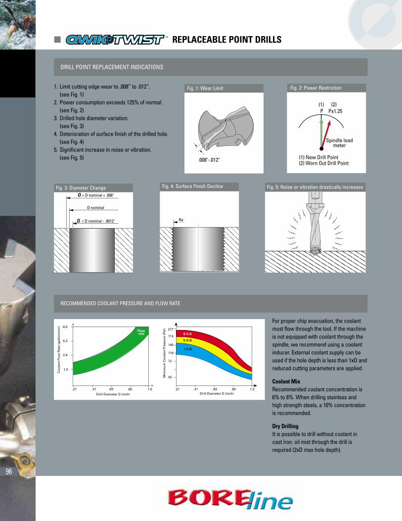
DRILL POINT REPLACEMENT INDICATIONS
Fig. 1: Wear Limit Fig. 2: Power Restriction
.008"-.012"
P Px1.25(1) (2)
Spindle loadmeter
(1) New Drill Point(2) Worn Out Drill Point
Fig. 3: Diameter Change Fig. 4: Surface Finish Decline Fig. 5: Noise or vibration drastically increases
1. Limit cutting edge wear to .008” to .012”.(see Fig. 1)
2. Power consumption exceeds 125% of normal. (see Fig. 2)
3. Drilled hole diameter variation.(see Fig. 3)
4. Deterioration of surface finish of the drilled hole.(see Fig. 4)
5. Significant increase in noise or vibration. (see Fig. 5)
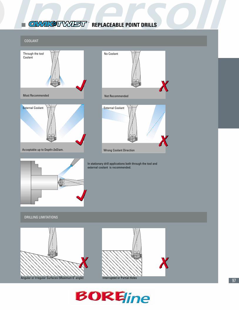
For proper chip evacuation, the coolantmust flow through the tool. If the machineis not equipped with coolant through thespindle, we recommend using a coolantinducer. External coolant supply can beused if the hole depth is less than 1xD andreduced cutting parameters are applied.
Coolant MixRecommended coolant concentration is6% to 8%. When drilling stainless andhigh strength steels, a 10% concentrationis recommended.
Dry DrillingIt is possible to drill without coolant incast iron. oil mist through the drill isrequired (2xD max hole depth).
RECOMMENDED COOLANT PRESSURE AND FLOW RATE
97
COOLANT
Through the toolCoolant
No Coolant
External Coolant
Acceptable up to Depth=2xDiam.
External Coolant
Wrong Coolant Direction
Most Recommended Not Recommended
In stationary drill applications both through the tool and external coolant is recommended.
DRILLING LIMITATIONS
Angular or Irregular Surfaces (Maximum 6˚ angle) Interrupted or Partial Holes
� REPLACEABLE POINT DRILLS
98
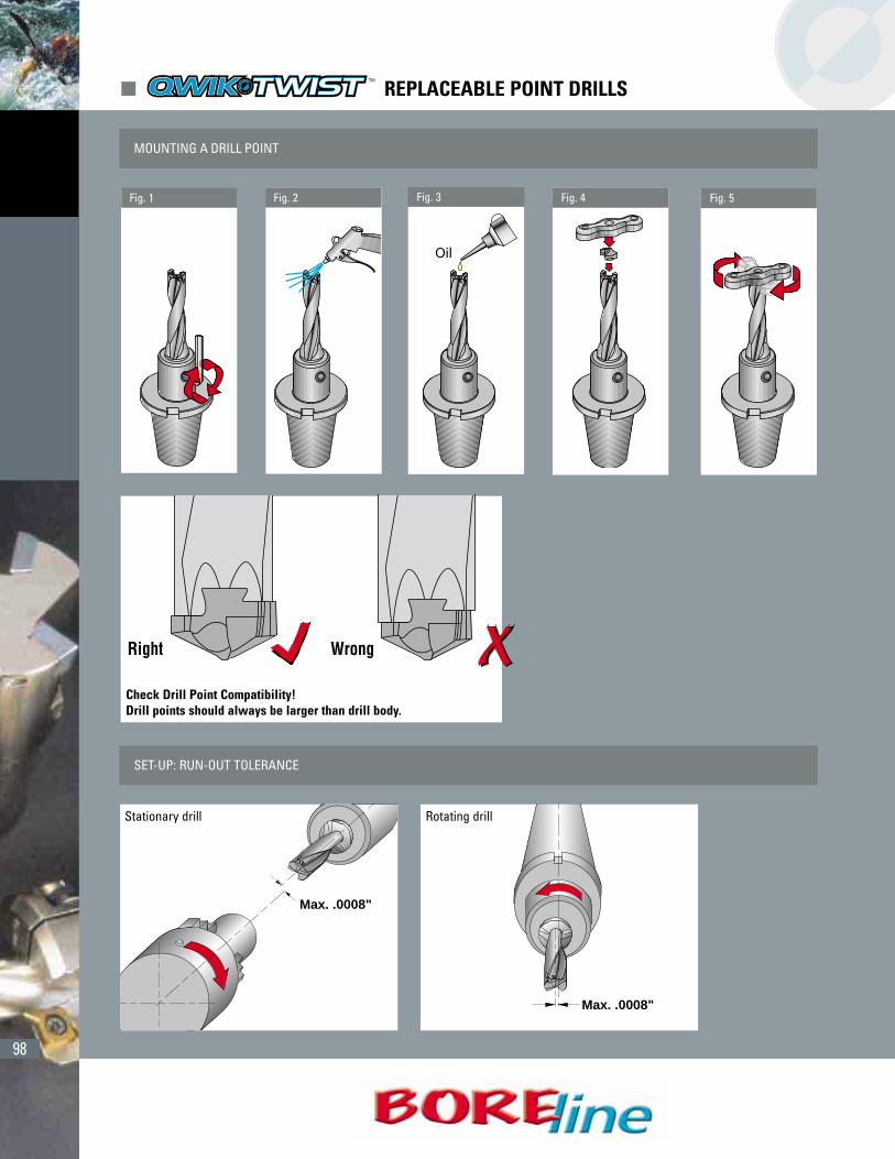
MOUNTING A DRILL POINT
Fig. 1
Check Drill Point Compatibility!Drill points should always be larger than drill body.
Fig. 2 Fig. 4 Fig. 5
SET-UP: RUN-OUT TOLERANCE
Max. .0008"
Stationary drill
Max. .0008"
Rotating drill
� REPLACEABLE POINT DRILLS
Fig. 3

99
POWER/FORCE REQUIREMENTS
Material: SAE 4340 Values change according to different materials andSpeed: 330 SFM drilling conditions.Feed: .008 ipr
QWIK•TWIST 8:1 DRILLS
• In case of stationary applications- on lathes- a high degree of radial and angular alignment between the chuck and the turret is required.
• The recommended cutting parameters for 8:1 drills is 20% lower than the cutting speeds used for the 3:1 and 5:1 drills.
Starter Hole Guide
We strongly recommend the use of a 3:1 Qwik•Twist drill of thesame diameter to drill a centering starter hole. The use of a centering starter hole improves hole location, accuracy, roundness,straightness and surface finish.
Starter Hole Depth
� REPLACEABLE POINT DRILLS

100
� CHAMFER RINGS
DRILLING AND CHAMFERING IN ONE OPERATION
Mounting Instructions:
1 Insert the Chamfer Ring on the drill body and slide to the desired position (1).
2 Rotate the ring clockwise until the stopper engages the flute edge.
3 Tighten the ring clamp screw according to the maximum tightening torque indicated in the table below.
4 Mount the chamfer insert. (Torque 35 in. lbs.).
5 Mount the Qwik•Twist Drill Point..
(1) Mount the ring on the drill body subject to the limitations shown in the drawing to the right and the position possibilities in the table “Chamfer Ring Position Range” on the next page.
Before drilling insure that:
• There exists a very small gap beween the chamfer insert and the drill body, butwithout contact (i.e., chamfer insert should not be in contact with the drill body).
• The cutting edge point (45˚) is aligned with the flute edge.
Maximum Tightening Torque- Ring Clamp ScrewRing Number Ring Clamp Screw Torque
CB100-01 thru CB150-01 SD050-A5 62 in. lbs.CB160-01 thru CB200-01 SD060-20 88 in. lbs.

101
User GuideRecommendation for better stability:
• Use 3xD drill instead of 5xD, if possible.
• Mount the ring as close as possible to the drill shank.
• In order to get better chamfer insert life, it is suggested to apply coolant to the chamfer insert in addition to the through the drill coolant and/or external coolant..
• A wider difference “X” between the drill body and the replaceable point size is preferred (i.e., for .575” replaceable point select .551” drill body rather than .571”). A slightly larger “X” dimension can dramatically increase the chamfer insert life.
Trouble Shooting
• Bad chamfer surface finish (vibrations)
Solutions:• Use a shorter drill.• Move the ring closer to the drill shank.• Reduce the cutting speed while cutting th chamfer.
• Chips packed on the ring flutes:• Ensure that the ring is positioned as shown in the mounting instructions.• Adjust the cutting speed.• Use a pecking cycle.
Chamfer Ring Position RangeDrill Drill Body 3xD Drill Body 5xD Maximum
Diameter L (min-max) L (min-max) Chamfer Size.394 .31-.63 .59-1.42.413 .31-.71 .67-1.54.433 .31-.75 .71-1.61.453 .31-.83 .79-1.73.472 .31-.87 .83-1.81.492 .31-.94 .91-1.93 .06.512 .31-.98 .94-2.01.531 .31-1.06 1.02-2.13.551 .35-1.14 1.10-2.24.571 .35-1.22 1.18-2.36.591 .35-1.18 1.14-2.36.630 .35-1.30 1.26-2.56.699 .43-1.38 1.34-2.72.709 .43-1.50 1.46-2.91 .08.748 .43-1.65 1.61-3.15.787 .43-1.77 1.73-3.35
The “L” dimension shown is for a .04” chamfer.For other sizes, adjust “L” accordingly.
� CHAMFER RINGS
102
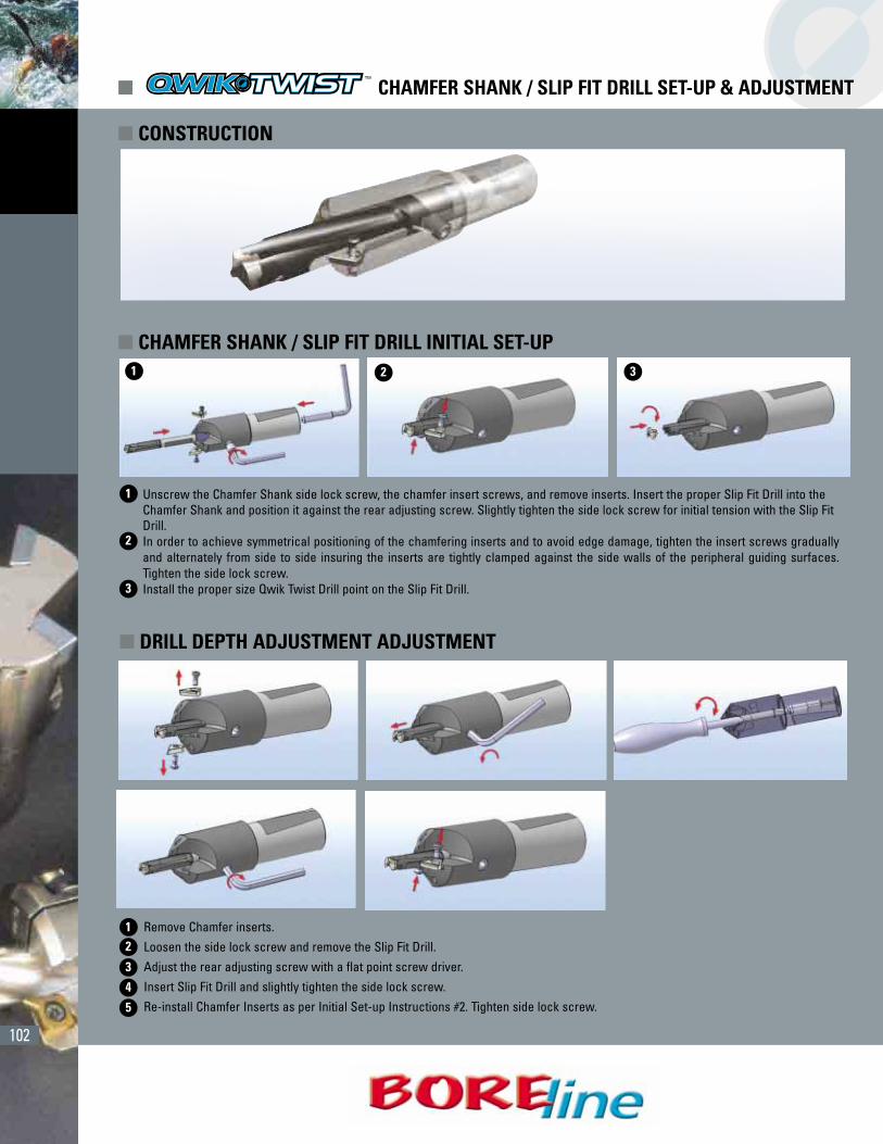
Remove Chamfer inserts.Loosen the side lock screw and remove the Slip Fit Drill.Adjust the rear adjusting screw with a flat point screw driver.Insert Slip Fit Drill and slightly tighten the side lock screw.Re-install Chamfer Inserts as per Initial Set-up Instructions #2. Tighten side lock screw.
� CHAMFER SHANK / SLIP FIT DRILL SET-UP & ADJUSTMENT
� CHAMFER SHANK / SLIP FIT DRILL INITIAL SET-UP
� DRILL DEPTH ADJUSTMENT ADJUSTMENT
� CONSTRUCTION
Unscrew the Chamfer Shank side lock screw, the chamfer insert screws, and remove inserts. Insert the proper Slip Fit Drill into the Chamfer Shank and position it against the rear adjusting screw. Slightly tighten the side lock screw for initial tension with the Slip FitDrill.In order to achieve symmetrical positioning of the chamfering inserts and to avoid edge damage, tighten the insert screws graduallyand alternately from side to side insuring the inserts are tightly clamped against the side walls of the peripheral guiding surfaces.Tighten the side lock screw.Install the proper size Qwik Twist Drill point on the Slip Fit Drill.
1
1
2
2
3
12
3
4
5
3
103
� PRODUCTIVITY TIPS
QuadDrills are One-Effective. Indexabledrills are one-effective cutting geometryregardless of the number of inserts in thetool. This is extremely important whenestablishing feeds and speeds for a givenoperation.
Rigidity. A high degree of rigidity of themachine and fixturing is critical for index-able drilling.
Spindle Rigidity. If the spindle is not tightor properly adjusted, the drill will cut off-center, producing oversize holes. Insertchipping or low tool life may also resultand hole finish will be affected.
Fixture Rigidity. Workpiece strength isessential. Flimsy or inadequately support-ed workpieces will render indexable drillsvirtually ineffective.
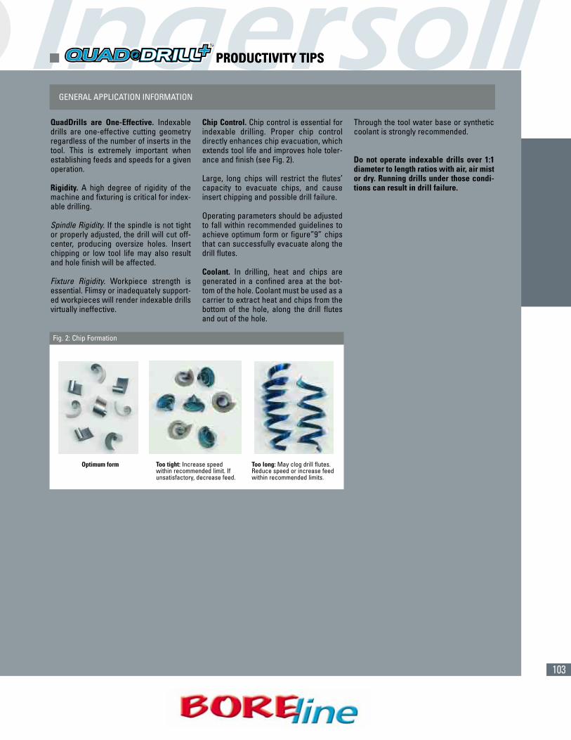
Chip Control. Chip control is essential forindexable drilling. Proper chip controldirectly enhances chip evacuation, whichextends tool life and improves hole toler-ance and finish (see Fig. 2).
Large, long chips will restrict the flutes’capacity to evacuate chips, and causeinsert chipping and possible drill failure.
Operating parameters should be adjustedto fall within recommended guidelines toachieve optimum form or figure”9” chipsthat can successfully evacuate along thedrill flutes.
Coolant. In drilling, heat and chips aregenerated in a confined area at the bot-tom of the hole. Coolant must be used as acarrier to extract heat and chips from thebottom of the hole, along the drill flutesand out of the hole.
Through the tool water base or syntheticcoolant is strongly recommended.
Do not operate indexable drills over 1:1diameter to length ratios with air, air mistor dry. Running drills under those condi-tions can result in drill failure.
GENERAL APPLICATION INFORMATION
Optimum form Too tight: Increase speedwithin recommended limit. Ifunsatisfactory, decrease feed.
Too long: May clog drill flutes.Reduce speed or increase feedwithin recommended limits.
Fig. 2: Chip Formation
� PRODUCTIVITY TIPS

104
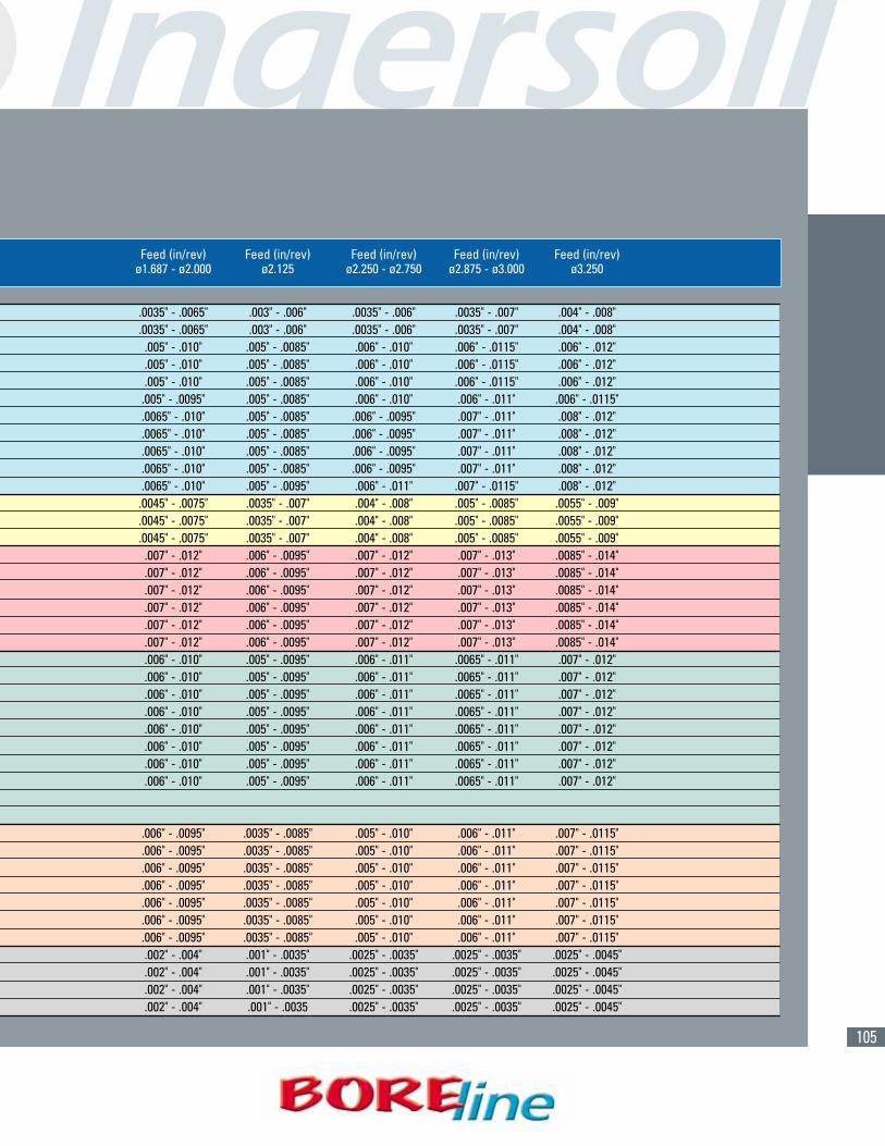
(CONT.)Material Cutting Feed (in/rev) Feed (in/rev) Feed (in/rev) Feed (in/rev) Feed (in/rev)
ISO Number Speed (SFM) ø.500 - ø.594 ø.625 - ø.813 ø.843 - ø1.063 ø1.094 - ø1.312 ø1.343 - ø1.625
1 800 - 1000 .002" - .004" .0025" - .004" .0025" - .005" .003" - .005" .003" - .006"2 800 - 1000 .002" - .004" .0025" - .004" .0025" - .005" .003" - .005" .003" - .006"3 500 - 800 .002" - .004" .003" - .006" .004" - .007" .005" - .0085" .005" - .0095"4 800 - 1000 .002" - .004" .003" - .006" .004" - .007" .005" - .0085" .005" - .0095"5 600 - 800 .002" - .004" .003" - .006" .004" - .007" .005" - .0085" .005" - .0095"6 500 - 800 .002" - .004" .003" - .0055" .004" - .007" .005" - .0085" .005" - .009"7 400 - 700 .002" - .005" .003" - .006" .004" - .007" .005" - .008" .006" - .009"8 400 - 600 .002" - .005" .003" - .006" .004" - .007" .005" - .008" .006" - .009"9 300 - 550 .002" - .005" .003" - .006" .004" - .007" .005" - .008" .006" - .009"
10 400 - 600 .002" - .005" .003" - .006" .004" - .007" .005" - .008" .006" - .009"11 400 - 550 .002" - .005" .003" - .006" .004" - .008" .005" - .009" .006" - .0095"12 550 - 800 .002" - .004" .003" - .006" .003" - .006" .0035" - .0065" .004" - .007"13 500 - 700 .002" - .004" .003" - .006" .003" - .006" .0035" - .0065" .004" - .007"14 500 - 700 .002" - .004" .003" - .006" .003" - .006" .0035" - .0065" .004" - .007"15 500 - 800 .002" - .004" .003" - .0065" .005" - .008" .006" - .010" .006" - .011"16 500 - 800 .002" - .004" .003" - .0065" .005" - .008" .006" - .010" .006" - .011"17 600 - 800 .002" - .004" .003" - .0065" .005" - .008" .006" - .010" .006" - .011"18 600 - 800 .002" - .004" .003" - .0065" .005" - .008" .006" - .010" .006" - .011"19 600 - 800 .002" - .004" .003" - .0065" .005" - .008" .006" - .010" .006" - .011"20 500 - 700 .002" - .004" .003" - .0065" .005" - .008" .006" - .010" .006" - .011"21 1300 - 2000 .002" - .005" .003" - .006" .004" - .008" .005" - .009" .0055" - .009"22 1000 - 1300 .002" - .005" .003" - .006" .004" - .008" .005" - .009" .0055" - .009"23 1300 - 2000 .002" - .005" .003" - .006" .004" - .008" .005" - .009" .0055" - .009"24 1000 - 1300 .002" - .005" .003" - .006" .004" - .008" .005" - .009" .0055" - .009"25 1000 - 1300 .002" - .005" .003" - .006" .004" - .008" .005" - .009" .0055" - .009"26 800 - 1000 .002" - .005" .003" - .006" .004" - .008" .005" - .009" .0055" - .009"27 750 - 900 .002" - .005" .003" - .006" .004" - .008" .005" - .009" .0055" - .009"28 800 - 1000 .002" - .005" .003" - .006" .004" - .008" .005" - .009" .0055" - .009"293031 100 - 250 .002" - .004" .0025" - .0055" .003" - .007" .004" - .0085" .0055" - .009"32 100 - 250 .002" - .004" .0025" - .0055" .003" - .007" .004" - .0085" .0055" - .009"33 100 - 250 .002" - .004" .0025" - .0055" .003" - .007" .004" - .0085" .0055" - .009"34 100 - 250 .002" - .004" .0025" - .0055" .003" - .007" .004" - .0085" .0055" - .009"35 100 - 250 .002" - .004" .0025" - .0055" .003" - .007" .004" - .0085" .0055" - .009"36 100 - 250 .002" - .004" .0025" - .0055" .003" - .007" .004" - .0085" .0055" - .009"37 100 - 200 .002" - .004" .0025" - .0055" .003" - .007" .004" - .0085" .0055" - .009"38 50 - 150 .001" - .002" .001" - .002" .001" - .003" .002" - .003" .002" - .003"39 50 - 150 .001" - .002" .001" - .002" .001" - .003" .002" - .003" .002" - .003"40 50 - 150 .001" - .002" .001" - .002" .001" - .003" .002" - .003" .002" - .003"41 50 - 150 .001" - .002" .001" - .002" .001" - .003" .002" - .003" .002" - .003"
Recommendations are starting parameters only and can be effected by cutting conditions such as spindal and fixture rigidity. Minimum150 psi coolant through the tool is required for proper drill performance. If not possible, then cutting parameters may have to be reduced. Start at the midpoint of the range and adjust the cutting parameters according to your cutting conditions.
For drills that are 4:1 length to diameter ratio, it may be necessary to reduce your feed by 40% for the first .06" of drilling depth. Thenincrease to full feed rate for the remainder of the cut.
� OPERATING GUIDELINES
P
M
K
N
H
S
= P =M = K = N = S = H
105
Feed (in/rev) Feed (in/rev) Feed (in/rev) Feed (in/rev) Feed (in/rev)ø1.687 - ø2.000 ø2.125 ø2.250 - ø2.750 ø2.875 - ø3.000 ø3.250
.0035" - .0065" .003" - .006" .0035" - .006" .0035" - .007" .004" - .008"
.0035" - .0065" .003" - .006" .0035" - .006" .0035" - .007" .004" - .008".005" - .010" .005" - .0085" .006" - .010" .006" - .0115" .006" - .012".005" - .010" .005" - .0085" .006" - .010" .006" - .0115" .006" - .012".005" - .010" .005" - .0085" .006" - .010" .006" - .0115" .006" - .012"
.005" - .0095" .005" - .0085" .006" - .010" .006" - .011" .006" - .0115"
.0065" - .010" .005" - .0085" .006" - .0095" .007" - .011" .008" - .012"
.0065" - .010" .005" - .0085" .006" - .0095" .007" - .011" .008" - .012"
.0065" - .010" .005" - .0085" .006" - .0095" .007" - .011" .008" - .012"
.0065" - .010" .005" - .0085" .006" - .0095" .007" - .011" .008" - .012"
.0065" - .010" .005" - .0095" .006" - .011" .007" - .0115" .008" - .012".0045" - .0075" .0035" - .007" .004" - .008" .005" - .0085" .0055" - .009".0045" - .0075" .0035" - .007" .004" - .008" .005" - .0085" .0055" - .009".0045" - .0075" .0035" - .007" .004" - .008" .005" - .0085" .0055" - .009"
.007" - .012" .006" - .0095" .007" - .012" .007" - .013" .0085" - .014"
.007" - .012" .006" - .0095" .007" - .012" .007" - .013" .0085" - .014"
.007" - .012" .006" - .0095" .007" - .012" .007" - .013" .0085" - .014"
.007" - .012" .006" - .0095" .007" - .012" .007" - .013" .0085" - .014"
.007" - .012" .006" - .0095" .007" - .012" .007" - .013" .0085" - .014"
.007" - .012" .006" - .0095" .007" - .012" .007" - .013" .0085" - .014"
.006" - .010" .005" - .0095" .006" - .011" .0065" - .011" .007" - .012"
.006" - .010" .005" - .0095" .006" - .011" .0065" - .011" .007" - .012"
.006" - .010" .005" - .0095" .006" - .011" .0065" - .011" .007" - .012"
.006" - .010" .005" - .0095" .006" - .011" .0065" - .011" .007" - .012"
.006" - .010" .005" - .0095" .006" - .011" .0065" - .011" .007" - .012"
.006" - .010" .005" - .0095" .006" - .011" .0065" - .011" .007" - .012"
.006" - .010" .005" - .0095" .006" - .011" .0065" - .011" .007" - .012"
.006" - .010" .005" - .0095" .006" - .011" .0065" - .011" .007" - .012"
.006" - .0095" .0035" - .0085" .005" - .010" .006" - .011" .007" - .0115"
.006" - .0095" .0035" - .0085" .005" - .010" .006" - .011" .007" - .0115"
.006" - .0095" .0035" - .0085" .005" - .010" .006" - .011" .007" - .0115"
.006" - .0095" .0035" - .0085" .005" - .010" .006" - .011" .007" - .0115"
.006" - .0095" .0035" - .0085" .005" - .010" .006" - .011" .007" - .0115"
.006" - .0095" .0035" - .0085" .005" - .010" .006" - .011" .007" - .0115"
.006" - .0095" .0035" - .0085" .005" - .010" .006" - .011" .007" - .0115".002" - .004" .001" - .0035" .0025" - .0035" .0025" - .0035" .0025" - .0045".002" - .004" .001" - .0035" .0025" - .0035" .0025" - .0035" .0025" - .0045".002" - .004" .001" - .0035" .0025" - .0035" .0025" - .0035" .0025" - .0045" .002" - .004" .001" - .0035 .0025" - .0035" .0025" - .0035" .0025" - .0045"
106
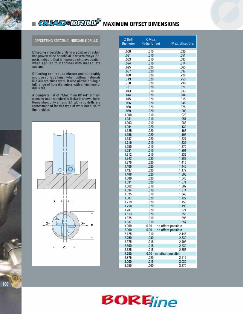
OFFSETTING ROTATING INDEXABLE DRILLS
Offsetting indexable drills in a positive directionhas proven to be beneficial in several ways. Re-ports indicate that it improves chip evacuationwhen applied to machines with inadequatecoolant.
Offsetting can reduce chatter and noticeablyimprove surface finish when cutting materialslike 316 stainless steel. It also allows drilling afull range of hole diameters with a minimum ofdrill sizes.
A complete list of “Maximum Offset” dimen-sions for each standard drill size is shown here.Remember, only 2:1 and 3:1 L/D ratio drills arerecommended for this type of work because oftheir rigidity.
Z Drill X Max. Diameter Radial Offset Max. offset Dia.
.500 .010 .520
.531 .010 .551
.563 .010 .583
.594 .010 .614
.625 .020 .665
.657 .020 .697
.688 .020 .728
.719 .020 .759
.750 .020 .790
.781 .020 .821
.813 .010 .833
.844 .020 .884
.875 .020 .915
.906 .020 .946
.938 .020 .978
.969 .020 1.0091.000 .010 1.0201.031 .010 1.0511.063 .010 1.0831.094 .020 1.1341.125 .020 1.1651.156 .020 1.1961.187 .020 1.2271.219 .010 1.2391.250 .010 1.2701.281 .010 1.3011.312 .010 1.3321.343 .020 1.3831.375 .020 1.4151.406 .020 1.4461.437 .020 1.4771.468 .020 1.5081.500 .020 1.5401.531 .020 1.5711.562 .010 1.5821.594 .010 1.6141.625 .010 1.6451.687 .020 1.7271.719 .020 1.7591.750 .020 1.7901.781 .020 1.8211.813 .020 1.8531.875 .010 1.8951.937 .010 1.9571.969 0.00 - no offset possible2.000 0.00 - no offset possible2.125 .010 2.1452.250 .040 2.3302.375 .015 2.4052.500 .015 2.5302.625 .015 2.6552.750 0.00 - no offset possible2.875 .020 2.9153.000 .015 3.0303.250 .060 3.370
� MAXIMUM OFFSET DIMENSIONS
107
� PRODUCTIVITY TIPS
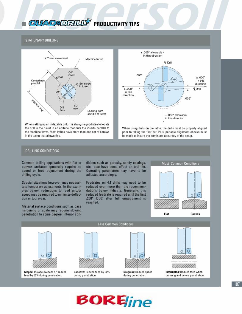
STATIONARY DRILLING
DRILLING CONDITIONS
When setting up an indexable drill, it is always a good idea to locatethe drill in the turret in an attitude that puts the inserts parallel tothe machine ways. Most lathes have more than one set of screwsin the turret that allows this.
When using drills on the lathe, the drills must be properly alignedprior to taking the first cut. Plus, periodic alignment checks mustbe made to insure the continued accuracy of the setup.
Less Common Conditions
Common drilling applications with flat orconvex surfaces generally require nospeed or feed adjustment during thedrilling cycle.
Special situations however, may necessi-tate temporary adjustments. In the exam-ples below, reductions to feed and/orspeed may be required to minimize deflec-tion or tool wear.
Material surface conditions such as casehardening or scale may require slowingpenetration to some degree. Interior con-
ditions such as porosity, sandy castings,etc., also have some effect on tool life.Operating parameters may have to beadjusted accordingly.
Feedrates on 4:1 drills may need to bereduced even more than the recommen-dations below indicate. Generally, thisreduced feedrate is required until the first.200” DOC after full engagement isreached.
Most Common Conditions
Flat Convex
Sloped: If slope exceeds 5°, reducefeed by 50% during penetration.
Interrupted: Reduce feed whencrossing and before penetration.
Concave: Reduce feed by 60%during penetration.
Irregular: Reduce speedduring penetration.
108
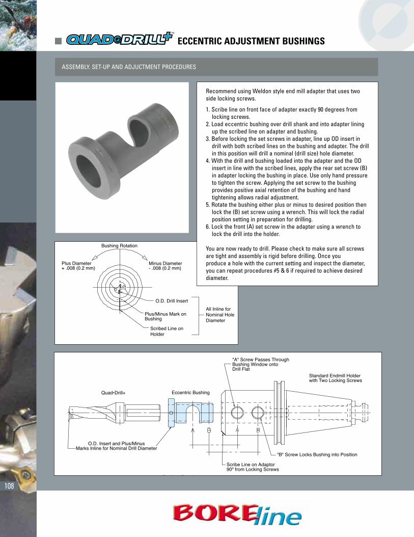
� ECCENTRIC ADJUSTMENT BUSHINGS
ASSEMBLY. SET-UP AND ADJUCTMENT PROCEDURES
Recommend using Weldon style end mill adapter that uses twoside locking screws.
1. Scribe line on front face of adapter exactly 90 degrees fromlocking screws.
2. Load eccentric bushing over drill shank and into adapter liningup the scribed line on adapter and bushing.
3. Before locking the set screws in adapter, line up OD insert indrill with both scribed lines on the bushing and adapter. The drillin this position will drill a nominal (drill size) hole diameter.
4. With the drill and bushing loaded into the adapter and the ODinsert in line with the scribed lines, apply the rear set screw (B)in adapter locking the bushing in place. Use only hand pressureto tighten the screw. Applying the set screw to the bushingprovides positive axial retention of the bushing and handtightening allows radial adjustment.
5. Rotate the bushing either plus or minus to desired position thenlock the (B) set screw using a wrench. This will lock the radialposition setting in preparation for drilling.
6. Lock the front (A) set screw in the adapter using a wrench tolock the drill into the holder.
You are now ready to drill. Please check to make sure all screwsare tight and assembly is rigid before drilling. Once youproduce a hole with the current setting and inspect the diameter,you can repeat procedures #5 & 6 if required to achieve desireddiameter.

109
(CONT.)Material Cutting Feed (in/rev) Feed (in/rev) Feed (in/rev) Feed (in/rev) Insert
ISO Number Speed (SFM) E.500 - E.750 E1.000 E.813 - E1.500 E1.625 - E2.000 Grade*
1 500 - 1000 .002" - .006" .004" - .007" .005" - .008" .006" - .010"2 500 - 1000 .002" - .006" .004" - .007" .005" - .008" .006" - .010"3 400 - 900 .002" - .006" .003" - .006" .004" - .007" .005" - .0085" IN 20054 700 - 900 .002" - .006" .003" - .006" .004" - .007" .005" - .0085"5 700 - 900 .002" - .006" .003" - .006" .004" - .007" .005" - .0085"6 500 - 800 .002" - .006" .003" - .0055" .004" - .007" .005" - .0085" IN 10307 500 - 800 .002" - .005" .003" - .006" .004" - .007" .005" - .008"8 500 - 800 .002" - .005" .003" - .006" .004" - .007" .005" - .008"9 500 - 800 .002" - .005" .003" - .006" .004" - .007" .005" - .008" IN 6515
10 350 - 550 .002" - .005" .003" - .006" .004" - .007" .005" - .008"11 350 - 550 .002" - .005" .003" - .006" .004" - .008" .005" - .009"12 450 - 750 .002" - .005" .004" - .006" .007" - .009" .008" - .010" IN 200513 375 - 600 .002" - .005" .004" - .006" .007" - .009" .008" - .010"14 375 - 600 .002" - .005" .004" - .006" .007" - .009" .008" - .010" IN 103015 500 - 800 .002" - .005" .003" - .0065" .004" - .007" .005" - .008"16 500 - 800 .002" - .005" .003" - .0065" .004" - .007" .005" - .008" IN 651517 600 - 800 .002" - .005" .003" - .0065" .004" - .007" .005" - .008"18 600 - 800 .002" - .005" .003" - .0065" .004" - .007" .005" - .008" IN 200519 600 - 800 .002" - .005" .003" - .0065" .004" - .007" .005" - .008"20 500 - 700 .002" - .005" .003" - .0065" .004" - .007" .005" - .008" IN 103021 1100 - 1800 .003" - .006" .004" - .006" .006" - .008" .007" - .010"22 800 - 1100 .003" - .006" .004" - .006" .006" - .008" .007" - .010" IN 30M23 1100 - 1800 .003" - .006" .004" - .006" .006" - .008" .007" - .010"24 800 - 1100 .003" - .006" .004" - .006" .006" - .008" .007" - .010" IN 103025 800 - 1100 .003" - .006" .004" - .006" .006" - .008" .007" - .010"26 600 - 800 .003" - .006" .004" - .006" .006" - .008" .007" - .010" IN 200527 550 - 700 .003" - .006" .004" - .006" .006" - .008" .007" - .010"28 600 - 800 .003" - .006" .004" - .006" .006" - .008" .007" - .010" IN 1030293031 100 - 250 .002" - .004" .003" - .005" .004" - .006" .005" - .007"32 100 - 250 .002" - .004" .003" - .005" .004" - .006" .005" - .007" IN 200533 100 - 250 .002" - .004" .003" - .005" .004" - .006" .005" - .007"34 100 - 250 .002" - .004" .003" - .005" .004" - .006" .005" - .007"35 100 - 250 .002" - .004" .003" - .005" .004" - .006" .005" - .007"36 100 - 250 .002" - .004" .003" - .005" .004" - .006" .005" - .007" IN 103037 100 - 200 .002" - .004" .003" - .005" .004" - .006" .005" - .007"38 50 - 150 .001" - .002" .001" - .002" .001" - .003" .002" - .003" IN 651539 50 - 150 .001" - .002" .001" - .002" .001" - .003" .002" - .003"40 50 - 150 .001" - .002" .001" - .002" .001" - .003" .002" - .003" IN 200541 50 - 150 .001" - .002" .001" - .002" .001" - .003" .002" - .003"
� 15S OPERATING GUIDELINES
P
M
K
N
S
H
= P =M = K = N = S = H

110
(CONT.)Material Cutting Feed (in/rev) Feed (in/rev) Feed (in/rev) Feed (in/rev) InsertISO Number Speed (SFM) E.438 - ø.719 E.812 E1.000 - ø1.500 E1.750 - ø2.000 Grade*
1 500 - 1000 .004" - .010" .006" - .011" .008" - .014" .010" - .016"2 500 - 1000 .004" - .010" .006" - .011" .008" - .014" .010" - .016"3 400 - 900 .004" - .010" .004" - .011" .007" - .012" .010" - .017" IN 20054 700 - 900 .004" - .010" .004" - .011" .007" - .012" .010" - .017"5 700 - 900 .004" - .010" .004" - .011" .007" - .012" .010" - .017"6 500 - 800 .004" - .010" .004" - .011" .007" - .012" .010" - .017" IN 10307 500 - 800 .004" - .009" .004" - .011" .007" - .012" .009" - .015"8 500 - 800 .004" - .009" .004" - .011" .007" - .012" .009" - .015"9 500 - 800 .004" - .009" .004" - .011" .007" - .012" .009" - .015" IN 6515
10 350 - 550 .004" - .009" .004" - .011" .007" - .012" .009" - .015"11 350 - 550 .004" - .009" .004" - .011" .008" - .014" .010" - .016"12 450 - 750 .004" - .009" .006" - .010" .012" - .016" .014" - .018" IN 200513 375 - 600 .004" - .009" .006" - .010" .012" - .016" .014" - .018"14 375 - 600 .004" - .009" .006" - .010" .012" - .016" .014" - .018" IN 103015 500 - 800 .004" - .009" .004" - .010" .007" - .013" .010" - .015"16 500 - 800 .004" - .009" .004" - .010" .007" - .013" .010" - .015" IN 651517 600 - 800 .004" - .009" .004" - .010" .007" - .013" .010" - .015"18 600 - 800 .004" - .009" .004" - .010" .007" - .013" .010" - .015" IN 200519 600 - 800 .004" - .009" .004" - .010" .007" - .013" .010" - .015"20 500 - 700 .004" - .009" .004" - .010" .007" - .013" .010" - .015" IN 103021 1100 - 1800 .006" - .011" .006" - .010" .012" - .015" .013" - .018"22 800 - 1100 .006" - .011" .006" - .010" .012" - .015" .013" - .018" IN 30M23 1100 - 1800 .006" - .011" .006" - .010" .012" - .015" .013" - .018"24 800 - 1100 .006" - .011" .006" - .010" .012" - .015" .013" - .018"25 800 - 1100 .006" - .011" .006" - .010" .012" - .015" .013" - .018" IN 103026 600 - 800 .006" - .011" .006" - .010" .012" - .015" .013" - .018"27 550 - 700 .006" - .011" .006" - .010" .012" - .015" .013" - .018"28 600 - 800 .006" - .011" .006" - .010" .012" - .015" .013" - .018" IN 1030293031 100 - 250 .004" - .007" .004" - .008" .007" - .011" .009" - .013"32 100 - 250 .004" - .007" .004" - .008" .007" - .011" .009" - .013" IN 200533 100 - 250 .004" - .007" .004" - .008" .007" - .011" .009" - .013"34 100 - 250 .004" - .007" .004" - .008" .007" - .011" .009" - .013"35 100 - 250 .004" - .007" .004" - .008" .007" - .011" .009" - .013"36 100 - 250 .004" - .007" .004" - .008" .007" - .011" .009" - .013" IN 103037 100 - 200 .004" - .007" .004" - .008" .007" - .011" .009" - .013"38 50 - 150 .002" - .003" .002" - .003" .002" - .005" .004" - .006" IN 651539 50 - 150 .002" - .003" .002" - .003" .002" - .005" .004" - .006"40 50 - 150 .002" - .003" .002" - .003" .002" - .005" .004" - .006" IN 200541 50 - 150 .002" - .003" .002" - .003" .002" - .005" .004" - .006"
� 15C OPERATING GUIDELINES
P
M
K
N
S
H
= P =M = K = N = S = H

111
(CONT.)
P
M
K
N
S
H
Material Cutting Speed Cutting Speed Cutting SpeedISO Number (SFM) (SFM) (SFM)
ø.078 - ø.197 ø.198 - ø.512 ø.513 - ø1.575
1 230 - 300 260 - 360 230 - 3302 230 - 300 260 - 360 230 - 3303 165 - 230 200 - 260 165 - 2304 230 - 300 260 - 360 230 - 3305 165 - 230 200 - 260 165 - 2306 200 - 260 230 - 300 200 - 2607 165 - 230 200 - 260 165 - 2308 165 - 230 200 - 260 165 - 2309 165 - 230 200 - 260 165 - 23010 165 - 230 200 - 260 165 - 23011 165 - 230 200 - 260 165 - 23012 165 - 230 165 - 230 165 - 23013 165 - 230 165 - 230 165 - 23014 165 - 230 165 - 230 165 - 23015 200 - 260 230 - 300 230 - 30016 200 - 260 230 - 300 230 - 30017 200 - 260 230 - 300 230 - 30018 200 - 260 230 - 300 230 - 30019 200 - 260 230 - 300 230 - 30020 200 - 260 230 - 300 230 - 30021 230 - 590 330 - 1000 330 - 100022 230 - 590 330 - 1000 330 - 100023 230 - 590 330 - 1000 330 - 100024 230 - 590 330 - 1000 330 - 100025 230 - 590 330 - 1000 330 - 100026 230 - 390 330 - 520 260 - 53027 230 - 390 330 - 520 260 - 53028 230 - 390 330 - 520 260 - 53029303132333435363738394041
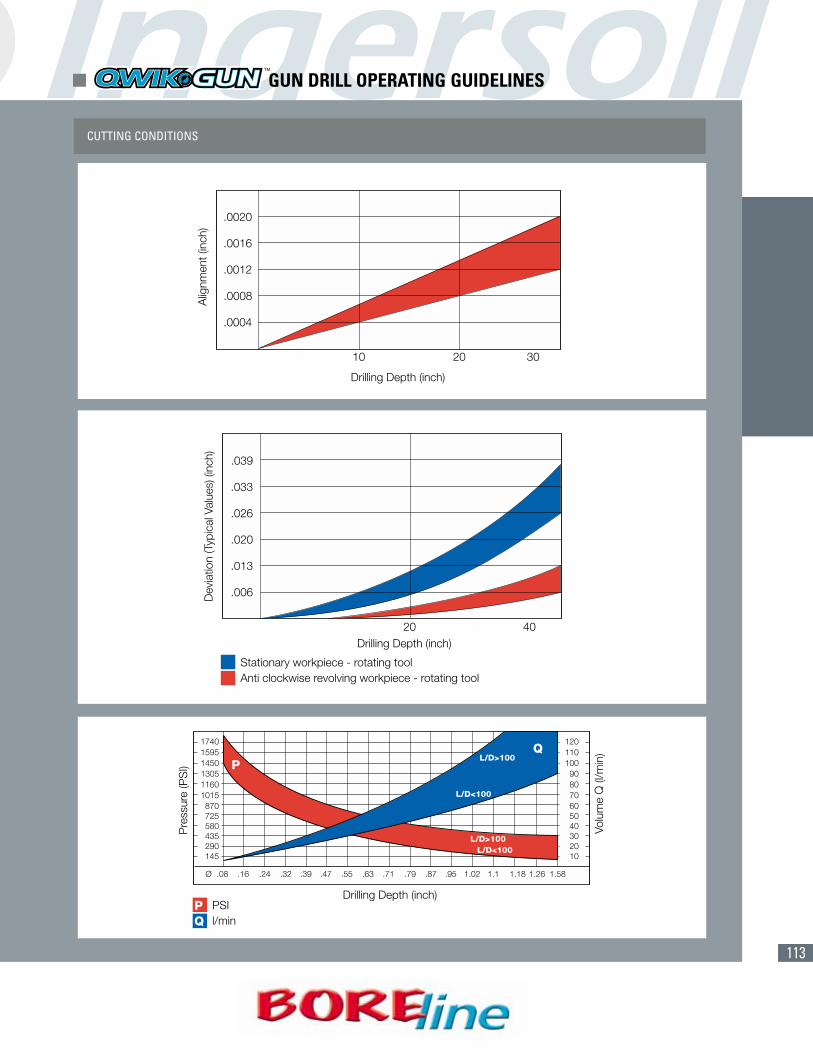
� GUN DRILL OPERATING GUIDELINES
112
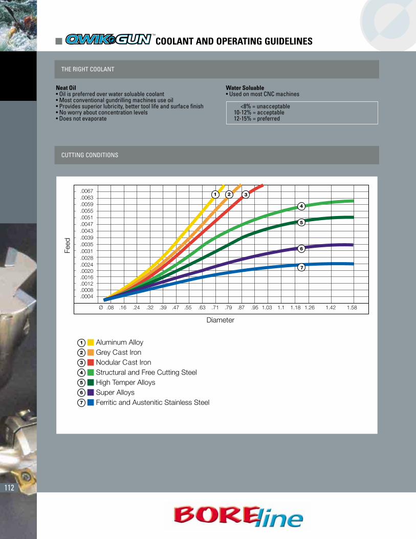
� COOLANT AND OPERATING GUIDELINES
THE RIGHT COOLANT
CUTTING CONDITIONS
Neat Oil• Oil is preferred over water soluable coolant• Most conventional gundrilling machines use oil• Provides superior lubricity, better tool life and surface finish• No worry about concentration levels• Does not evaporate
Water Soluable• Used on most CNC machines
<8% = unacceptable10-12% = acceptable12-15% = preferred
113
CUTTING CONDITIONS
� GUN DRILL OPERATING GUIDELINES