gps l1 civil signal modernization (l1c) · navstar global positioning system space and missile...
TRANSCRIPT

THE INTERAGENCY GPS EXECUTIVE BOARD
STEWARDSHIP PROJECT #204
GPS L1 Civil Signal Modernization (L1C)
JULY 30, 2004
Kenneth W. Hudnut, Ph.D. L1C Project Civil Co-Leader Department of the Interior United States Geological Survey (626)583-7232 [email protected]
Bryan Titus, Captain, USAF L1C Project Military Co-Leader Navstar Global Positioning System Space and Missile Systems Center (310)363-6899 [email protected]

This report represents an input to the U.S. Government based on astudy sponsored and funded by the Interagency GPS Executive Board. The findings and recommendations in the report do not represent anofficial policy of the U.S. Government or programmatic decision of anyacquisition executive of the U.S. Government.

L1C Project i Final Report
Table of Contents
1.0 EXECUTIVE SUMMARY .............................................................................................. 1
2.0 INTRODUCTION............................................................................................................. 3
3.0 PROJECT OBJECTIVES................................................................................................ 4
4.0 PROCESS DESCRIPTION ............................................................................................. 5
4.1 Overview ............................................................................................................................ 5
4.2 Technical Feasibility Determination ............................................................................... 7
4.3 Expert Presentations and Questionnaires ...................................................................... 8
4.4 User Group Interviews ................................................................................................... 10
5.0 EXPERT INTERVIEW RESULTS AND ANALYSIS ............................................... 10
5.1 Technical Feasibility Results.......................................................................................... 10
5.2 Expert Interview Results................................................................................................ 13
5.2.1 Response Statistics and Summary ............................................................................ 13
5.2.2 Should L1C be Implemented? .................................................................................. 16
5.2.3 Modulation Preferences ............................................................................................ 17
5.2.4 The Message Data Rate Dilemma............................................................................. 18
5.2.5 Data Rate Analysis and Recommendation................................................................ 21
5.3 Expert Interview Signal Recommendations ................................................................. 24
6.0 MARKET SEGMENT SIGNAL NEEDS AND USER FEEDBACK ........................ 25
6.1 Single-Frequency Applications Dominate .................................................................... 26
6.2 Which will be the Single Frequency of Choice?........................................................... 27
6.3 Market Segments ............................................................................................................ 29
6.3.1 Consumer Product Needs for a New Signal ............................................................. 29
6.3.2 Aviation Signal Requirements .................................................................................. 30
6.3.3 Professional and Scientific Signal Requirements ..................................................... 31
6.4 User Interviews................................................................................................................ 32
7.0 CONCLUSIONS AND RECOMMENDATIONS........................................................ 33
8.0 ACKNOWLEDGEMENTS: .......................................................................................... 34

L1C FINAL REPORT
TABLE OF ATTACHMENTS
A-1.0: L1C Initial Presentation at CGSIC; Portland, Oregon; September 8, 2003 ...........A 2A-1.1: Presentation and Questionnaire Provided at NAVCEN Booth
during ION GPS-2003............................................................................ A 13A-1.2: GPS World article on L1C Project (October 2003 issue) ........................ A 18
A-2.0: L1C Presentation at GPS System Engineering Forum (GSEF); Los Angeles,California; October 28-29, 2003 ........................................................................ A 19
A-3.0: L1C Paper presented at International Civil Aviation Organization (ICAO) - AirNavigation Conference (ANC), Navigation Systems Panel (NSP); Canberra,Australia; November 11, 2003 ........................................................................... A 44A-3.1: L1C ‘flimsy’ for ICAO ANC NSP feedback .......................................... A 48A-3.2: ICAO Contracting States listing ............................................................. A 54
A-4.0: L1C Presentation at International GPS Service (IGS) 10th Annual Meeting; Berne,Switzerland; March 3, 2004 ............................................................................... A 59A-4.1: L1C Poster – presented at IGS Meeting.................................................. A 74
A-5.0: L1C Presentation (Parts I & II) at IEEE PLANS; Monterey, California; April 28,2004 .................................................................................................................. A 75
A-6.0: Annotated L1C Technical Interview Presentation ............................................ A 108A-6.1: Questionnaire Used for Experts Survey................................................ A 134
A-7.0: L1C Technical Questionnaire Responses (55 responses included).................... A 136
A-8.0: Civil User Benefits .......................................................................................... A 347A-8.1: User Group Guidelines......................................................................... A 392
A-9.0: Economic Benefits........................................................................................... A 395
ii

L1C Project 1 Final Report 7/30/04 5:05 PM
1.0 Executive Summary The objective of this document is to report the findings of the L1 Civil Signal Modernization (L1C) Stewardship Project (Technical Project #204) to the Interagency GPS Executive Board (IGEB) in support of policy decisions about whether or not to endorse a 4th civil signal on the Navstar Global Positioning System (GPS). The report also provides support for decisions about what characteristics are most important for this potential new civil GPS signal. The IGEB funded this project in August of 2003 to provide recommendations (based both on technical work and stakeholder feedback) on whether or not a modernized civil signal (L1C) could and should be added at L1. Because of funding restrictions, the objectives and the results were limited to:
1. Determine if it would be possible, technically, to insert a new civil GPS navigation signal at the L1 frequency in addition to the C/A code, P(Y) code, M code, and Interplex code.
Our technical team evaluated this issue and concluded it is possible to add L1C
while maintaining a constant transmitted signal amplitude and preserving “flex” power control options.
2. Determine if a broad and representative range of civil GPS experts and users want L1C in
addition to the current C/A code.
Based on small group presentations followed by questionnaires to centers of GPS expertise, including U.S. government agencies, GPS equipment manufacturers, and university departments specializing in GPS applications, 55 responses were received from around the world. The survey result is unambiguous that L1C is desired, even at the expense of a slight reduction in the C/A signal power.
3. Determine what L1C signal characteristics would be most desirable for the widest range
of user applications. In particular, two key characteristics were evaluated:
a. Modulation waveform, with the options being BOC(1,1) and BOC(5,1). (Note: BOC(1,1) was accepted as the modulation template through EU/US negotiations during the course of this project. At one time the Galileo team was evaluating subtle alternatives to BOC(1,1). If a better modulation is found which meets the EU/US agreements on signal compatibility, the U.S. should be prepared to implement it instead of BOC(1,1). However, such a replacement would have to be studied very carefully, justified thoroughly, and is very unlikely.)
The survey result is clear that most experts prefer BOC(1,1) for all L1C
potential applications.
b. Message data rate and content, with the options being 25, 50, and 100+ bits per second (bps)

L1C Project 2 Final Report
The answer is clear, although with less unanimity, that L1C should provide a data rate of 25 bps with no additional messages. This optimizes signal robustness for all applications. An equal number of requests were made for a higher data rate, although for at least three different and conflicting requirements, not all of which could be accommodated concurrently. This recommendation leaves differential GPS signals, integrity messages, long duration orbit and clock parameters, or simply faster orbit and clock parameters to other communication services, which either exist now or are rapidly developing, and which are better suited to these specialized tasks.
Had the originally requested funding been available, this project would have next addressed specific technical design issues in order to prepare high-level L1C signal recommendations to guide development and documentation of L1C signal details, including:
A proposed specific method of adding L1C to the existing suite of L1 signals Details of the recommended modulation waveform, e.g., BOC(1,1) A recommended code generation method, and recommended code lengths, for each of
the two L1C signal components A recommended forward error correction algorithm and additional message content if
needed Should additional funding be made available, we recommend these follow-on actions and would be pleased to continue our work:
Contact all the survey respondents and additional interested parties, asking them to review this report in order to fully validate or, if necessary, slightly modify its conclusions
Perform technical studies to determine how best to incorporate the L1C signal Review forward error correction (FEC) options to determine if changing from the
current L2C and L5 standard would be worth the potential improvement in error rate Propose specific code generation methods and code lengths for each L1C signal
component Prepare a top level signal description to enable the Interface Control Working Group
(ICWG) to develop detailed specifications Interact with the GPS/Galileo interoperability working groups to optimize the
worldwide civil user benefits while protecting allied military effectiveness This IGEB Stewardship Project has been successful in establishing the feasibility, desirability, and some of the key characteristics of an L1C signal. The processes used to reach these conclusions included (a) assembly of a technical team to conduct analyses and then reach conclusions during a two-day meeting at the GPS Joint Program Office (JPO), (b) public presentations and papers that supported the overall goals of the project, answered questions, and elicited feedback, (c) individual technical presentations to GPS experts in government agencies, GPS companies, and at universities to obtain specific recommendations on an L1C questionnaire, and (d) interviews with user groups to determine the benefits GPS now provides and what improvements would be most helpful to their applications. This report documents the processes,

L1C Project 3 Final Report
the materials created, the results obtained, and the conclusions and recommendations reached, as delineated at the beginning of this Executive Summary. The L1C team wishes to express its thanks to the IGEB Senior Steering Group (SSG) and the Director’s office of the IGEB Executive Secretariat for enabling this study and for guidance during this nearly year-long effort. We also are particularly grateful for the time and effort of the many organizations and their staff who participated in the expert group briefings and responded with meaningful answers, comments, and suggestions. Without this volunteer work, from around the world, the project could not have succeeded. Through it all, it was gratifying to find clear answers to important questions about the future of GPS. Finally, it is important to highlight the splendid working relationship between the GPS JPO and the USGS. Both parties worked cooperatively to fully protect national security interests while providing civil users the best possible service. This project has been an excellent example of dual-use GPS stewardship. 2.0 Introduction GPS is in the midst of a radical, albeit gradual, transformation. From launch of the first GPS satellite in 1978 through all of 2003 there have been only three navigation signals on only two frequencies. With these signals, GPS has completely changed how the world navigates. However, over the next several years the number of navigation signals will increase from three to seven and the number of frequencies from two to three. In addition, the new signals will have substantially better characteristics, including a pilot carrier, much longer codes, the use of forward error correction, and a more flexible message structure with much better resolution. New and modern civil signals will be on L2 and on the new L5 frequency. The current GPS modernization plan, however, leaves the L1 frequency with only the outdated C/A signal for civil applications. With the addition of L1C, all three GPS frequencies would then provide a modernized civil signal, completing the GPS modernization process. There is good reason to concentrate attention on L1. Today it carries C/A, the only civil GPS signal. In the future, even with new and modern L2 and L5 signals, L1 is expected to remain the most important civil frequency. This is primarily because it is less affected by ionospheric refraction error than L2 or L5. (L1 has only 61% of the L2 error and 56% of the L5 error.) This inherent advantage relative to L2 and L5 helps motivate the basic goal of this project. The L1C project was initiated to determine whether it would be technically possible to add L1C to an already crowded suite of L1 signals, to determine whether GPS users could use and would welcome L1C, and to determine what L1C characteristics would be most valuable for the broadest range of GPS users. This report documents the activities, the presentation materials, the processes used, the results we have obtained, and the conclusions we have reached. Section 3.0, immediately below, reviews the Project Objectives. It recognizes that the objectives had to be narrowed because of funding restrictions, and it defines the steps that would have been taken next without these restrictions (or that can be taken next if funds become available).

L1C Project 4 Final Report
Section 4.0 then provides a description of the processes used to achieve these objectives. The overview in Section 4.1 includes a review of supporting activities, including multiple presentations, literally around the world. Section 4.2 then describes the evaluation process used to determine whether L1C technically can be added to the other L1 signals. Section 4.3 defines the process of reaching out to a wide range of worldwide GPS experts, defining the L1C issues through multiple presentations to small government, industry, and academic centers, and obtaining valuable answers and comments from the overwhelming majority. Section 4.4 describes the parallel process of interviewing many GPS users to determine how GPS is valuable and what improvements they would most appreciate. Section 5.0 presents and evaluates the expert interview results. Included in Section 5.1 is a discussion of the technical evaluation of the GPS L1 signal structure to determine whether one more signal can be added, while retaining the required characteristics of a constant amplitude composite signal and the ability to control the allocation of power to each individual signal. Section 5.2 reports the results from the expert surveys, statistically evaluating the source of the responses, whether the experts support the addition of L1C, which modulation is preferred by the experts, the apparent data rate dilemma, and how the dilemma was resolved. Section 5.3 summarizes the signal recommendations based on the expert interviews. Section 6.0 provides an overview of user signal requirements by market segment. It then summarizes results from informal user group interviews. Users were asked why and how GPS is useful and important now and what improvements would be most appreciated. Section 7.0 presents the Project Conclusions and Recommendations, and Section 8.0 offers acknowledgements to the key participants. This report also includes a large number of attachments. These include most of the presentation materials used during the project. Of particular importance are:
Attachment 6.0 Presentation given to most of the GPS experts, explains the issues and the options
Attachment 6.1 Questionnaire the experts were asked to return with answers and comments
Attachment 7.0 The 55 individual responses to the questionnaires Attachment 8.0 Review of user group needs and perspectives
3.0 Project Objectives The objectives have been narrowed since this project was first proposed in August 2003. There are two reasons for this. First, the funding was about half what had been requested, so we de-scoped accordingly, reducing our planned level of effort on both the technical work and stakeholder feedback work. Second, the U.S. and the European Union (EU) commenced and recently completed negotiations about the compatibility of Galileo L1 signals with both military and civil GPS signals. As part of these negotiations, the U.S. Department of State offered that the U.S. would implement a new signal on L1 with BOC(1,1) modulation if Europe would do the same on Galileo. Although there is room for both sides to deviate somewhat from this particular

L1C Project 5 Final Report
modulation, as long as the compatibility requirements are met, the specific modulation question was no longer as important a question for this project to resolve. Therefore, the narrowed L1C project objectives have been to:
1. Determine technical feasibility of adding another civil GPS navigation signal at the L1 frequency in addition to the C/A code, P(Y) code, M code, and Interplex code signals.
2. Determine, by means of presentations and interviews, if a broad and representative range of civil GPS experts and users want an L1C in addition to the current C/A code.
3. Determine what L1C signal characteristics would be most desirable for the widest range of user applications. In particular, two key characteristics were evaluated:
a. Modulation waveform, with the options being BOC(1,1) and BOC(5,1) (Note: BOC(1,1) was chosen as the preferred modulation template through US/EU negotiations during the course of this project, although there is room for further evaluation and a different agreement by both parties.)
b. Message data rate and content, with the options being 25, 50, and 100+ bps
4. Prepare a high-level L1C signal specification to guide development of the signal details, including:
c. A proposed method of adding L1C to the existing suite of L1 signals d. A recommended modulation waveform, e.g., BOC(1,1) e. Recommended code generation and code lengths for the two L1C signal components f. Recommended data rate, forward error correction, and additional message content if
needed
Objectives 1, 2 and 3 have been accomplished to the extent possible with resources available, on time and on budget. The 4th objective has not been realized due to limited resources. The following section describes the methods we used to achieve the first three objectives. 4.0 Process Description 4.1 Overview Three main activities were used to achieve the project objectives. The first was to determine the feasibility of adding another signal to the already crowded L1 signal structure. Ever since the start of GPS there have been two signals at L1, the C/A code and the P(Y) code, which are transmitted in phase quadrature. A key objective has always been for the composite signal to have a constant amplitude in order to maximize transmitter efficiency. Thus, to add the two components of the new military M code required some clever engineering. Chip by chip multiplexing of the M code is used to provide both a data signal component and a data-less, or pilot carrier, signal component in a single bi-phase composite signal. To achieve a constant transmitted signal amplitude, a fourth “Interplex” signal was then introduced. Therefore, to add the two components of an L1C signal while maintaining a constant amplitude was seen as quite a challenge. This activity also assessed the potential interference of L1C to legacy C/A receivers, recognizing that full backward compatibility is essential. After considerable preliminary work, a

L1C Project 6 Final Report
two-day technical meeting was held early in the project to address L1C feasibility as well as other issues related to design and implementation of the L1C signal (see Section 4.2). The second activity was to obtain feedback from GPS experts around the world on whether or not, and – if so – how best to configure an L1 modernized signal. Based on this expert input, recommendations would be made on what specific L1C characteristics would best serve the worldwide user base. Section 4.3 describes this process and Section 5 describes the results. The third activity was to obtain feedback from GPS user communities about the benefits GPS now provides and what improvements would be most helpful to their applications. We did not expect technical guidance from these interviews, but it was important to get an overall impression of what applications were being served, what was working well, and what type of improvements would be most beneficial. The following sections explain these three activities in more detail, but before that it also is important to characterize the scope of related meetings, presentations, and papers which supported the overall goals of this project. For example, multiple presentations were made to inform stakeholders about the L1C Project, to answer their questions, and to elicit their feedback. This effort began at the 42nd CGSIC meeting forum on 8 September 2003 in Portland, Oregon (Attachment 1.0). Immediately after the CGSIC meeting the presentation was continuously shown at the USCG NAVCEN booth throughout ION GPS-2003 and a document which combined the presentation with a questionnaire (Attachment 1.1) was made available. Subsequently, GPS World published an article introducing the L1C Project to the global GPS user community (Attachment 1.2). Additional major L1C presentations included the following, all of which are documented in attachments to this report:
(A) The L1C Project group technical meeting, held at the GPS JPO on 8-9 October, 2003. Material developed for and presented at this meeting led to the GPS System Engineering Forum (GSEF) technical review presentation on 28-29 October, 2003 in Los Angeles, California (Attachment 2.0). See Section 4.2 of this report.
(B) International Civil Aviation Organization (ICAO) - Air Navigation Conference (ANC), Navigation Systems Panel (NSP); Canberra, Australia Nov. 11, 2003 (Attachments 3.0, 3.1 and 3.2). Presentations and user feedback by Taylor and Dorfler.
(C) Meeting with the Japan GPS Council (JGPSC) stakeholder group in Tokyo, Japan on 23 January 2004 using the expert group presentation and questionnaire (Attachments 6.0 and 6.1). Presentations and user feedback by Titus and Stansell.
(D) The International GPS Service (IGS) 10th annual symposium; invited presentation and poster on 3-4 March 2004 in Berne, Switzerland (Attachments 4.0 & 4.1) by Stansell.
(E) The L1C Project presentations and stakeholder feedback sessions formed a prominent part of the IEEE PLANS conference special session on GPS Modernization on 28 April 2004 at Monterey, California (Attachments 5.1 & 5.2). Presentations and user feedback by Hudnut and Stansell.
We also expect to present our findings at upcoming meetings of the CGSIC, the ION, and other groups during the upcoming year, as requested and as opportunities arise.

L1C Project 7 Final Report
A summary and chronology of L1C project presentations and meetings is given in Table 4.1.
Table 4.1 - Chronology of L1C Project Presentations and Meetings:
Date Event 7 August 2003 Joint L1C team planning meeting (at GPS JPO) 28 August Joint L1C team planning meeting (at GPS JPO) w/ D. Turner 3 September Joint meeting with Aerospace for GPS III briefing (at GPS JPO) 5 September Meeting re. L1C Project with Mr. Mike Shaw (at GPS JPO)
5 Sept. (late a.m.) Meeting with Aerospace experts on worst case aggregate global interference calculations (at GPS JPO)
8 September CGSIC 42nd Meeting: L1C presentation and participation in panel open forum; Mr. Hank Skalski, chairman (Portland) http://www.navcen.uscg.gov/cgsic/meetings/default.htm
10-12 September ION Meeting L1C display at USCG NAVCEN booth 23 September Civil IFOR meeting; Mr. Hank Skalski, chairman (DC) 24 September L1C core group strategy & planning meeting (at GPS JPO) 8-9 October L1C Project – Initial Technical Meeting (at GPS JPO) 20 October L1C user meeting with Larry Young, NASA/JPL (at USGS) 28-29 October GSEF Meeting presentation (at ARINC) 11 November ICAO ANC NSP, Canberra, Australia 23 January L1C Meeting with JGPSC, Tokyo, Japan
3-4 March L1C Presentation & Poster at International GPS Service (IGS) 10th Annual Meeting, Berne, Switzerland
10 March CGSIC 43rd Mtg.: L1C Presentation (Hothem); Arlington, VA http://www.navcen.uscg.gov/cgsic/meetings/default.htm
20 April Joint team progress review meeting (at GPS JPO)
22 April L1C Presentation at ION Southern California Section http://www.ion.org/sections/southcalifornia.cfm
28 April L1C Presentation and Group Interview at IEEE PLANS, session and forum on GPS Modernization, Monterey, California --- all presentations available at http://www.igeb.gov/outreach/
29 June Joint team progress review meeting (at GPS JPO)
20-21 Sept. CGSIC Long Beach, CA --- Invited --- L1C Project Final Report (will speak and be an open forum panel participant)
4.2 Technical Feasibility Determination The L1 frequency now carries two GPS signals, C/A and P(Y). Beginning in 2005, IIR-M satellites will be launched with two additional signals on L1, M code and the Interplex code which is there only to maintain a constant transmitter signal amplitude. Another important requirement on all new satellites is “flex power”, the ability to command a relative power increase or decrease on any of the signal components. With the existing signals and the constraints of constant amplitude and flex power, adding yet another L1 signal could be difficult at best. Therefore, the initial question was whether adding L1C technically was feasible.
L1C Project 8 Final Report
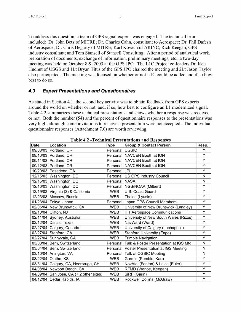
To address this question, a team of GPS signal experts was engaged. The technical team included: Dr. John Betz of MITRE; Dr. Charles Cahn, consultant to Aerospace; Dr. Phil Dafesh of Aerospace; Dr. Chris Hegarty of MITRE; Karl Kovach of ARINC; Rich Keegan, GPS industry consultant; and Tom Stansell of Stansell Consulting. After a period of analytical work, preparation of documents, exchange of information, preliminary meetings, etc., a two-day meeting was held on October 8-9, 2003 at the GPS JPO. The L1C Project co-leaders Dr. Ken Hudnut of USGS and 1Lt Bryan Titus of the GPS JPO chaired the meeting and 2Lt Jason Taylor also participated. The meeting was focused on whether or not L1C could be added and if so how best to do so. 4.3 Expert Presentations and Questionnaires As stated in Section 4.1, the second key activity was to obtain feedback from GPS experts around the world on whether or not, and, if so, how best to configure an L1 modernized signal. Table 4.2 summarizes these technical presentations and shows whether a response was received or not. Both the number (54) and the percent of questionnaire responses to the presentations was very high, although some invitations to receive a presentation were not accepted. The individual questionnaire responses (Attachment 7.0) are worth reviewing.
Table 4.2 -Technical Presentations and Responses Date Location Type Group & Contact Person Resp. 09/08/03 Portland, OR Personal CGSIC Y 09/10/03 Portland, OR Personal NAVCEN Booth at ION Y 09/11/03 Portland, OR Personal NAVCEN Booth at ION Y 09/12/03 Portland, OR Personal NAVCEN Booth at ION Y 10/20/03 Pasadena, CA Personal JPL Y 12/15/03 Washington, DC Personal US GPS Industry Council N 12/15/03 Washington, DC Personal NASA N 12/16/03 Washington, DC Personal NGS/NOAA (Milbert) Y 12/19/03 Virginia (2) & California WEB U.S. Coast Guard Y 12/23/03 Moscow, Russia WEB Thales (Lyusin) Y 01/23/04 Tokyo, Japan Personal Japan GPS Council Members Y 02/06/04 New Brunswick, CA WEB University of New Brunswick (Langley) Y 02/10/04 Clifton, NJ WEB ITT Aerospace Communications Y 02/11/04 Sydney, Australia WEB University of New South Wales (Rizos) Y 02/12/04 Dallas, Texas WEB NavWard (Ward) Y 02/27/04 Calgary, Canada WEB University of Calgary (Lachapelle) Y 02/27/04 Stanford, CA WEB Stanford University (Enge) Y 02/27/04 Sunnyvale, CA WEB Trimble Navigation Y 03/03/04 Bern, Switzerland Personal Talk & Poster Presentation at IGS Mtg. N 03/04/04 Bern, Switzerland Personal Poster Presentation at IGS Meeting N 03/10/04 Arlington, VA Personal Talk at CGSIC Meeting N 03/22/04 Olathe, KS WEB Garmin (Pemble, Kao) Y 03/31/04 Calgary, CA, Heerbrugg, CH WEB NovAtel (Fenton) & Leica (Euler) Y 04/08/04 Newport Beach, CA WEB RFMD (Warloe, Keegan) Y 04/09/04 San Jose, CA (+ 2 other sites) WEB SiRF (Garin) Y 04/12/04 Cedar Rapids, IA WEB Rockwell Collins (McGraw) Y

L1C Project 9 Final Report
04/22/04 El Segundo, CA Personal Southern California ION Section Meeting N 04/28/04 Monterey, CA Personal PLANS Conference Y 05/14/04 Columbus, OH WEB Ohio State University (Brzezinska) Y 06/29/04 Campbell, CA WEB Qualcomm (Krasner) Y 06/29/04 Lexington, MA WEB MIT Lincoln Laboratory Y 07/02/04 Frederick, MD WEB AOPA Y 07/09/04 Athens, OH WEB Ohio University (Braasch) Y
Almost immediately after the L1C project was approved there were important opportunities to begin technical outreach. Therefore, a technical presentation and a questionnaire (Attachments 1.0 and 1.1) were prepared quickly and taken to the September 2003 CGSIC and ION GPS meetings in Portland, Oregon. Dr. Ken Hudnut participated on a CGSIC GPS Modernization panel and gave the L1C presentation on September 8. During the ION meeting the presentation was continuously shown at the NAVCEN exhibit booth, a stack of questionnaires was available, and Tom Stansell was present to answer questions. The initial questionnaire was intended to be self-explanatory, showing the presentation material in the left column and questions on the right. These early efforts resulted in a gratifying number of useful responses. The same questionnaire also was used in a technical discussion at the Jet Propulsion Laboratory on October 20, 2003. By December of 2003 the issues were in better focus and both a new presentation and a simplified questionnaire were created. Minor improvements were made to these documents in the months to follow. The final version of the presentation, with a written explanation for each chart, and the final questionnaire are included as Attachments 6.0 and 6.1. Reading this material will help you interpret the individual questionnaire responses included as Attachment 7.0 and evaluated below. Table 4.2, above, lists the date of each presentation or other outreach effort, the audience, and whether or not there was a response. It is always difficult to obtain meaningful feedback from a questionnaire, but we are pleased with both the quantity and the quality of responses received. It should be noted that although many of the presentations were made in person by one of the team members, a large number were presented remotely over the Internet. Some of these were to several sites simultaneously. Each site projected a web browser page on a conference room screen. The presenter controlled which slide was being shown, could move a pointer on the screen, and verbally communicated by speakerphone. For example, on December 19, 2003, a presentation was made simultaneously to U.S. Coast Guard facilities at Alexandria, VA, Portsmouth, VA, and Petaluma, CA. Using the web permitted worldwide participation, including presentations in Australia, Canada, Russia, and Switzerland. The technical presentations were intended for GPS experts who could provide guidance in what signal characteristics would most benefit their constituents. This included Government agencies and laboratories, GPS companies, and University professors and graduate students. These experts provided valuable feedback from most GPS application perspectives, including land, sea, air, and space, and with requirements ranging from the highest possible precision to the lowest possible cost.

L1C Project 10 Final Report
4.4 User Group Interviews As described in Section 4.1, the third activity was to conduct interviews with user groups in order to gain non-technical feedback on L1C design considerations. Making use of the User Group Guidelines (Attachment 8.1), members of the L1C Project team were asked to identify users and speak with them about the project. Furthermore, additional information was gleaned from reports that had been developed previously for related purposes. The interviews were intended to evoke responses that might either confirm or refute previously understood user interests in the range of possible capabilities of L1C, depending on which signal design parameter is used. For example, users who would benefit most from a low data rate would be those wishing to have better performance in wooded, urban, or even indoor environments. The interviews also were used to capture new considerations about ways in which L1C could better meet the navigation requirements of user groups. 5.0 Expert Interview Results and Analysis 5.1 Technical Feasibility Results Section 4.2 is a review of the process used to determine whether an additional signal could be added to the already-planned suite of L1 signals. The challenge was not simply to add a new signal but at the same time to maintain a constant total signal amplitude. This is needed to maximize satellite power efficiency. Also, it is important to be able to adjust the relative power level of each signal component (flex power). Several ways were found to achieve these objectives, so the question of technical feasibility was answered in the affirmative. Another aspect of the study was to evaluate the compatibility of L1C with the existing C/A signal, with the military M code signal, and with potential Galileo signals. Every signal in the L1 band interferes to some degree with all the others. Current civil users do not want L1C to adversely affect performance by significantly raising the noise floor of C/A receivers. National security interests require sufficient spectral separation of L1C from the M code signal, and it also limits the total power of both L1 civil signals combined. As with C/A signals, L1C signals interfere with each other. Therefore, it is important to set power levels with all these parameters in mind. The technical meeting confirmed ways to evaluate these factors and made preliminary assessments. Figure 5.1 illustrates that spectral separation of signals in the L1 band was a very important consideration. Figure 5.2 illustrates that an important part of the analysis was to consider signal “hot spots”, i.e., places on earth where the total power received from all satellites in view reaches a maximum during some part of the day. These are areas where interference between signals is at its worst during part of each day. These calculations not only depend on the satellite orbits but, importantly, they depend on assumptions about the gain of receiver antennas.

L1C Project 11 Final Report
Fig. 5.1 – Spectral Separation Considerations
Combined constellation (GPS & Galileo) results for global aggregate power. (Raghavan and Cooper, The Aerospace Corp.)
Fig. 5.2 – Illustration of Signal Hot Spot Analysis

L1C Project 12 Final Report
Fig. 5.3 – Power Allocation Presentation Slide 15 (Attachment 6.0)
As a result of these efforts, decisions were reached about which signals and what power levels would best fit the constraints. A summary of these results was presented soon afterwards by Hudnut and Titus, at the invitation of the GPS Systems Engineering Forum (GSEF), at their meeting on October 28-29, 2003 (see Attachment 2.0). Also, Figure 5.3 was developed and has been a key part of the presentation to GPS experts (Slide 15 of Attachment 6.0). The following paragraphs are a brief summary of the October 8-9, 2003 meeting and its key decisions. An initial classified session, led by Titus and including nearly all of the participants in the following main meeting, identified the power level and signal modulation options considered acceptable to the U.S. Government. A range of several possible signal modulations was reviewed, and trade-offs were carefully considered. The BOC(1,1) signal modulation arose as being both acceptable and also preferred by most participants as the best overall solution. Signal aggregate power was discussed and reviewed. The evaluation approach and algorithms which had been used by Titus and Betz during negotiations with the EU Galileo team were applied to this analysis as well. It was agreed that L1C would carry at least the same messages that will be carried by L2C and L5. Discussion of signal structure and modulation options, as well as multiplexing and coding techniques, led to the conclusion that design and implementation of L1C is feasible. Partly because of the 1.5 dB increase in specified minimum C/A signal power, L1C can be added without negative impact on C/A receivers. It was decided that the C/A signal will be continued indefinitely. The promise of a data-less channel and increased power, as well as enhanced GNSS interoperability, were agreed to be main user benefits from a technical standpoint.

L1C Project 13 Final Report
It was agreed that user feedback, primarily from technical experts throughout the GPS manufacturing and international community, would be gathered as a next step. Now that a limited and concrete number of questions could be asked, this greatly simplified the questionnaire. That is, the form distributed after our initial presentation (Attachment 1.1) asked for user feedback on a wider range of issues, some of which were decided on at our technical meeting. Following that, we were able to identify just those key few questions upon which user feedback would be most critical to L1C design. So, the interview process was modified and a new questionnaire developed to accompany the technical interview process from this point forward. The new technical presentation (annotated slide set in Attachment 6.0) and questionnaire (Attachment 6.1) became highly effective tools for gaining technical stakeholder input on those questions where a range of options remained open. After the technical sessions were completed, the meeting participants then discussed and agreed to help with a process of eliciting stakeholder feedback using an approach suggested by Joe Dorfler. The approach is based on his prior experience with similar efforts determining user requirements for WAAS and GPS III. The approach is to gain input from non-technical GPS users, and the results have been developed into the material described in Section 4.4. 5.2 Expert Interview Results A key element of the L1C project was to interview GPS experts around the world to determine:
• If a broad and representative range of civil GPS experts and users wanted an L1C signal in addition to the present C/A code, although with slightly reduced C/A signal power
• What L1C signal characteristics would be most desirable for the widest range of user
applications. In particular, two key characteristics were evaluated: Modulation waveform, with the options being BOC(1,1) and BOC(5,1) Message data rate and content, with the options being 25, 50, and 100+ bps
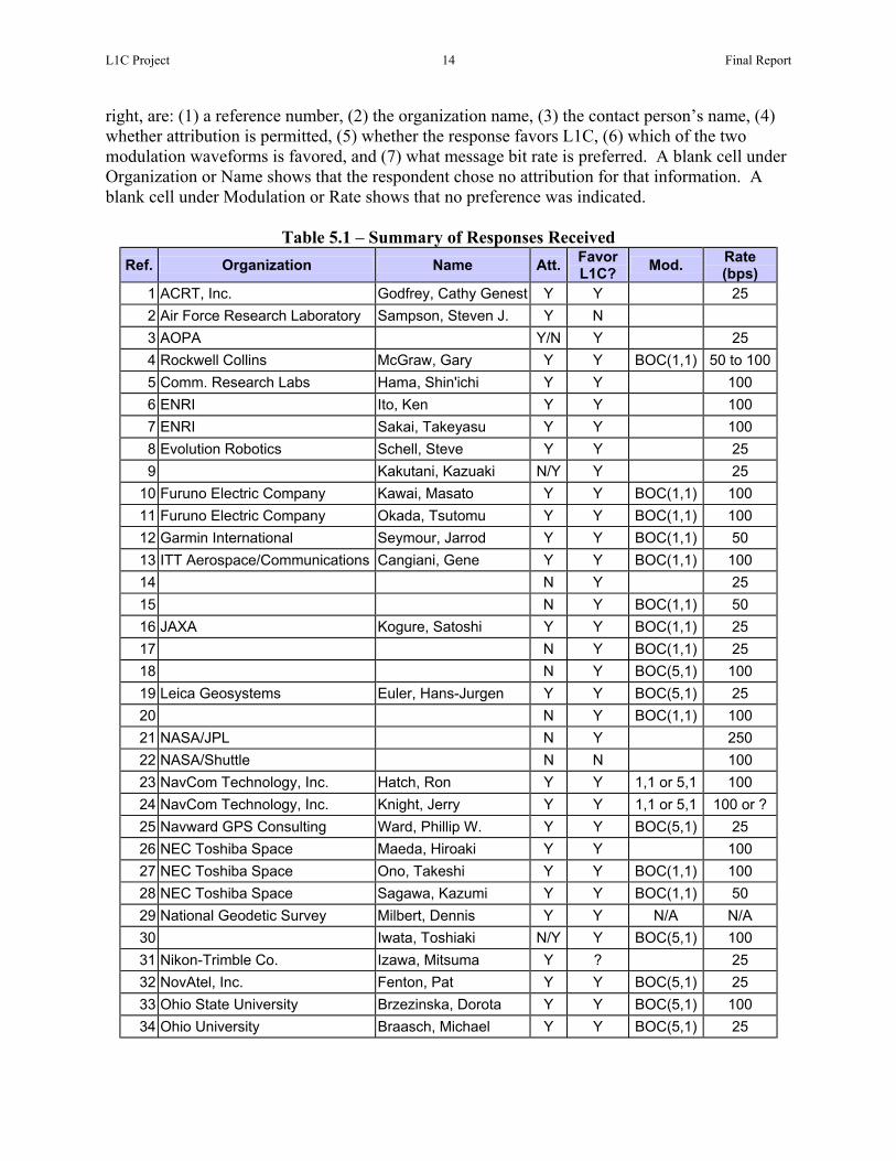
Attachment 6.0 is an annotated version of the presentation, and Attachment 6.1 is the expert’s questionnaire form. This Section 5.2 of the report is an evaluation and analysis of the expert responses, which are individually included in Attachment 7.0. Subsection 5.2.5 of this section offers conclusions and recommendations based on the expert responses. 5.2.1 Response Statistics and Summary In many cases an organization would create one consolidated response after a presentation. In other cases several people from an organization would respond separately, often with different recommendations. Therefore, it isn’t straightforward to imply an organizational response from differing personal responses. In the opposite sense, an organizational response may actually represent the opinion of just one person or, at most, a very few people. Recognizing these difficulties and accepting the potential distortion caused by mixing personal and presumed organizational responses, the following statistics are based simply on the number of responses received. Answers to key questions are summarized in Table 5.1. The headings, from left to
L1C Project 14 Final Report
right, are: (1) a reference number, (2) the organization name, (3) the contact person’s name, (4) whether attribution is permitted, (5) whether the response favors L1C, (6) which of the two modulation waveforms is favored, and (7) what message bit rate is preferred. A blank cell under Organization or Name shows that the respondent chose no attribution for that information. A blank cell under Modulation or Rate shows that no preference was indicated.
Table 5.1 – Summary of Responses Received Ref. Organization Name Att. Favor
L1C? Mod. Rate (bps)
1 ACRT, Inc. Godfrey, Cathy Genest Y Y 25 2 Air Force Research Laboratory Sampson, Steven J. Y N 3 AOPA Y/N Y 25 4 Rockwell Collins McGraw, Gary Y Y BOC(1,1) 50 to 100 5 Comm. Research Labs Hama, Shin'ichi Y Y 100 6 ENRI Ito, Ken Y Y 100 7 ENRI Sakai, Takeyasu Y Y 100 8 Evolution Robotics Schell, Steve Y Y 25 9 Kakutani, Kazuaki N/Y Y 25
10 Furuno Electric Company Kawai, Masato Y Y BOC(1,1) 100 11 Furuno Electric Company Okada, Tsutomu Y Y BOC(1,1) 100 12 Garmin International Seymour, Jarrod Y Y BOC(1,1) 50 13 ITT Aerospace/Communications Cangiani, Gene Y Y BOC(1,1) 100 14 N Y 25 15 N Y BOC(1,1) 50 16 JAXA Kogure, Satoshi Y Y BOC(1,1) 25 17 N Y BOC(1,1) 25 18 N Y BOC(5,1) 100 19 Leica Geosystems Euler, Hans-Jurgen Y Y BOC(5,1) 25 20 N Y BOC(1,1) 100 21 NASA/JPL N Y 250 22 NASA/Shuttle N N 100 23 NavCom Technology, Inc. Hatch, Ron Y Y 1,1 or 5,1 100 24 NavCom Technology, Inc. Knight, Jerry Y Y 1,1 or 5,1 100 or ? 25 Navward GPS Consulting Ward, Phillip W. Y Y BOC(5,1) 25 26 NEC Toshiba Space Maeda, Hiroaki Y Y 100 27 NEC Toshiba Space Ono, Takeshi Y Y BOC(1,1) 100 28 NEC Toshiba Space Sagawa, Kazumi Y Y BOC(1,1) 50 29 National Geodetic Survey Milbert, Dennis Y Y N/A N/A 30 Iwata, Toshiaki N/Y Y BOC(5,1) 100 31 Nikon-Trimble Co. Izawa, Mitsuma Y ? 25 32 NovAtel, Inc. Fenton, Pat Y Y BOC(5,1) 25 33 Ohio State University Brzezinska, Dorota Y Y BOC(5,1) 100 34 Ohio University Braasch, Michael Y Y BOC(5,1) 25

L1C Project 15 Final Report
35 Panasonic Automotive Systems Ishigaki, Toshihiro Y Y 100 36 pcisys (?) Lee, Ron Y N 37 Pioneer Corporation Ando, Hitoshi Y Y 50 38 Pioneer Corporation Kigure, Yoshiyuki Y Y BOC(1,1) 39 Qualcomm Krasner, Norman Y Y BOC(1,1) 100 40 RF Micro Devices (RFMD) Warloe, Andreas Y Y BOC(1,1) 25 41 SiRF Technology, Inc Garin, Lionel Y Y BOC(1,1) 25 42 Stanford University Enge, Per Y Y BOC(1,1) 25 43 Thales Navigation Lyusin, Sergey Y Y BOC(1,1) 100 44 Thales Navigation Snow, Robert Y Y BOC(1,1) 50 45 University of New Brunswick Beran, Tomas Y Y BOC(1,1) 25 46 University of New Brunswick Wang, Chaochao Y Y BOC(1,1) 25 47 University of New South Wales Babu, Ravindra Y Y BOC(1,1) 100 48 University of New South Wales Jia, Xiaodong Y Y BOC(1,1) 25 49 University of New South Wales Mumford, Peter Y Y 25 50 University of New South Wales Rizos, Chris Y Y BOC(1,1) 100 51 University of Calgary Lachapelle & Team Y Y BOC(1,1) 50 52 University of Sydney Quigley, Aaron Y Y BOC(1,1) 25
53 US Coast Guard, C2CEN Wolfe, Parsons, Cleveland Y Y BOC(1,1) 25
54 US Coast Guard, NAVCEN Schutzenhofer, John Y Y BOC(1,1) 25 55 Trimble Y/N
Note: The last input (Ref. # 55) was received after the following analyses were completed. Therefore, because this input also did not address the specific questions, it was not included in the statistics.
Of the first 54 total responses to the survey, it is interesting to see where in the world they originated. Figure 5.1 shows the distribution. The largest number, but less than half, were from the U.S. The second largest number were from Japan. A number of these were the result of our activities at the September 2003 CGSIC and ION GPS meetings in Portland, OR. A larger number were stimulated by one presentation to multiple companies at the Japan GPS Council (JGPSC) meeting in Tokyo on January 23, 2004. Together the U.S. and Japan produced 80% of all responses. Primarily because of academic interest and a response from NovAtel, Australia and Canada produced the third and fourth largest number of responses. Finally, there was one response from Russia on behalf of Thales Navigation and one from Switzerland for Leica Geosystems.
Fig. 5.1 – Distribution of Responses by Country

L1C Project 16 Final Report
The lack of response from Europe was not for lack of trying. There were as many, if not more, European companies and delegates at the September ION meeting as Japanese delegates. A number of European companies and universities were invited directly, but there was no response. A paper and a poster display were presented in Bern Switzerland at an IGS meeting during March, 2004 with no results. Perhaps some Europeans considered interest in L1C to be controversial with respect to the Galileo program. 5.2.2 Should L1C be Implemented?
Figure 5.2 shows the distribution of responses to the question of whether a new civil GPS signal should be added at the L1 frequency, even at the expense of reduced C/A signal power, or conversely whether a more powerful C/A signal should be the only civil signal on L1. The results are overwhelming and unambiguous that Government agencies, GPS manufacturers, and University researchers agree that
L1C is desirable. This is true for all realms of use: Land, Sea, Air, and even Space. (Note there were two different responses from NASA, one from JPL and the other from the Shuttle program. The first wanted L1C and the second didn’t, even though the Shuttle response asked for a 100 bps data rate which would be possible only if L1C were implemented.) The full spectrum of user equipment requirements, from the highest precision products to products requiring the lowest possible cost, were favorable to having L1C. The advantages of having a data-less pilot carrier, of having longer codes to reduce or eliminate cross-correlation and narrowband interference problems, of a higher precision and more flexible message structure, and of forward error correction and other message improvements clearly are recognized as desirable improvements for essentially all applications.
Fig. 5.2 – Is L1C Wanted?
The nearly unanimous desire to add L1C is tempered by the insistence that C/A code remain for the indefinite future in order to support many millions of legacy receivers. It would not be acceptable to substitute L1C for C/A, it must be an additional signal. (However, the signal designers must define a way for L1C to continue if, several decades from now, it does become feasible to discontinue the C/A signal. In other words, turning C/A off is not planned but if it were to happen it must not affect what then perhaps could be a billion or more L1C receivers.)

L1C Project 17 Final Report
5.2.3 Modulation Preferences Figure 5.3 shows the distribution of responses to the question of which modulation waveform is preferred for L1C, i.e., BOC(1,1) or BOC(5,1). Fifty percent of the respondents selected BOC(1,1) and 33% had no preference. A relatively small 13% preferred BOC(5,1), and the remaining 4% would be satisfied with either waveform. From a purely statistical perspective, BOC(1,1) is the “winner”. Although this preference may have been greatly iboth GPS and Galileo, a number of the waveform over the other, and it is instruresponses which preferred BOC(5,1), th
a) The reason of BOC(5,1), we chpresent L1 C/A. (Leica Geosys
b) Expecting advances in signal p
of BOC(5,1) will be feasible in University, Ref. # 33)
c) Both the BOC (1,1) and the BO
provides less interference bothtracking accuracy. (Ohio Unive
Of the 27 respondents who preferred BO
d) We have concerns that the widdifficult to design and produce BOC(1,1) is preferred. (Rockw
e) BOC (1,1) appears to be a safe
grounds. (Ref. # 20)
f) BOC(1,1) with 2X Minimum C/Aboth autonomous and wireless
g) Select BOC(1,1) signal since th
BOC(5,1) has a much wider basampling rate. The BOC(1,1) smany code edges than a normDevices, Ref. # 40)
h) We believe BOC(1,1) is the be
lower bandwidth, and therefore
Fig. 5.3 – Modulation Preference
nfluenced by the US/EU agreement to use BOC(1,1) on respondents had solid reasons for preferring one ctive to review some of these comments. Of the seven ree had supporting comments, which were:
ose it because it will be able to minimize the interference with tems, Ref. # 19)
rocessing to continue at the current pace, the implementation the planned time frame for modernization. (Ohio State
C (5,1) are acceptable. The BOC (5,1) is preferred since it to M-code and the C/A-code and it can offer better code-loop rsity, Ref. # 34)
C(1,1), some of the key comments were:
er bandwidth of the BOC(5,1) signal would make it extremely a practical Navwar prevent notch filter. For this reason, the ell Collins, Ref. # 4)
choice at this time based on both technical and political
power is a good compromise to improvement in sensitivity in assisted modes. (Qualcomm, Ref. # 39)
e full bandwidth can be supported by consumer chipsets. The ndwidth [therefore] requiring a wider Rx bandwidth and higher ignal can improve code tracking since there are twice as
al C/A code without the wider bandwidth penalties. (RF Micro
st modulation scheme for the modern signal because of its lower power consumption. Combined with the longer code

L1C Project 18 Final Report
suggested below, it will also support our cross-correlation requirements. (SiRF Technology, Ref. # 41)
i) On balance, I would expect that BOC(1,1) would be more readily useable by aviation,
because of correlation subpeak ambiguities. To my recollection, BOC(1,1) has subpeaks every 150 meters, whereas BOC(5,1) would have subpeaks every 30 meters. Failure to correctly resolve the BOC(1,1) subpeak would be readily detectable by RAIM, but the 30 meter ambiguity may be difficult to detect using RAIM. Hence, it has a greater prospect of hazardously misleading information (HMI). This risk can be offset by using multiple correlation samples per satellite, but this practice increases the cost of the avionics. In addition, the precision advantage of BOC(5,1) is not that important to aviation, because we use carrier smoothing. (Stanford University, Ref. # 42)
j) BOC(5,1) is undesirable, because wide bandwidth will lead to the following disadvantages for
consumer products: a) high sampling frequency and as result bigger power consumption; b) problems with harmonics and digital noise because of wideband RF. (Thales Navigation, Ref. # 43)
k) In order to have more robust position solutions, the BOC(1,1) signal appears to have better
characteristics than the BOC(5,1) because of its more isolated and lower autocorrelation secondary peaks (relative to the main peak), even if this implies a slightly higher multipath impact. It is however likely that in the coming years, new techniques will reduce this impact of multipath to a smaller scale. (University of Calgary, Ref. # 51)
Overall, it seems BOC(1,1) is a safe and effective choice. To choose BOC(5,1) would require much more study and a very convincing rationale. It also would require revision of the current EU/US agreement to use BOC(1,1) as the template for the new L1 signal. Although this is very unlikely, it is not impossible, because BOC(5,1) meets the EU/US negotiated compatibility criteria somewhat better than BOC(1,1). 5.2.4 The Message Data Rate Dilemma
Whereas there is near universal agreement that a modernized L1C signal would be desirable, there seems to be a complete stalemate on the question of message bit rate. As shown by Figure 5.4, 41% of the total responses support a 25 bps data rate and another 41% support 100 bps or higher. Only 11% support retaining the traditional 50 bps rate, and 7% have no preference. Those who support 25 bps are
unified on a single goal, which is to receive the GPS messages under marginal signal conditions, whether those conditions are due to foliage attenuation, weak indoor signals, or if operating in a high interference environment. That the supporters of 25 bps are unified is an important observation and it affects the interpretation of results. Pertinent comments from supporters of 25 bps include:
Fig. 5.4 – Message Bit Rate Preference

L1C Project 19 Final Report
1) L1 C/A is great, but we still have trouble - lots of trouble - under tree canopy, coverage is
spotty. Improved use in wooded area important to us. We often work under trees and in urban areas. Indoor use would open up a whole new industry. (ACRT Inc., Ref. # 1)
2) Based on the discussions during the briefing, it appears that the new L-1C should focus on
the 25bps option. (AOPA, Ref. # 3)
3) Improved performance indoors and under foliage would be most desirable. (Evolution Robotics, Ref. # 8)
4) The lower data rate (25 bps) is preferred since it extends system performance in low signal-
strength environments. The TTFF concerns can easily be eliminated simply by placing a day’s worth of ephemeris messages onto the web and other media. (Rockwell Collins, Ref. # 34)
5) The 25bps choice is my choice since it makes decoding bits possible at phase lock threshold
of the un-modulated carrier component. The downside is that it will take twice as long to get the ephemeris. That is somewhat mitigated by the new message structure being proposed. (RF Micro Devices, Ref. # 40)
6) For sensitivity improvement, we would like to go as low as possible in bit rate, 25bits per
second. (SiRF Technology, Ref. # 41) 7) On balance, I prefer the low data rate alternative, since the highest available data rate of 100
bps would have a hard time supporting aviation time to alarm requirements. Our time to alarm requirement for Category I precision approach is 6 seconds, which probably allows one second for message duration. At 100 bps, this dictates a maximum message length of 100 bits. Of these, 24-32 bits must be used for error detection (parity), and so the messaging efficiency would be at between 68% and 76%, which is low compared to today’s systems like WAAS. (Stanford University, Ref. # 42)
8) It will be useful to maintain lock in foliated areas. The users who may benefit from that could
be land surveyors, automobile navigation users and GPS-equipped cell phone users. (University of New Brunswick, Ref. # 45)
9) High speed of data is not the objective of GPS. It can be addressed with satellite
communication. (etc.) (University of New South Wales, Ref. # 48)
10) I need signals under trees (University of New South Wales, Ref. # 49) 11) I chose 25 bps over 50 bps since I feel it is more important to be able to acquire a message
in poor signal conditions than having a faster TTFF. (Rockwell Collins, Ref. # 54) In contrast, supporters of 100+ bps have three completely different and mutually exclusive objectives. The first group wants GPS to provide integrity and/or differential correction messages, much like an SBAS system. Galileo signal designers presumably intend to use their L1 OS signal for this purpose, transmitting messages at 125 bps. Note that comment (6) above from Professor Per Enge of Stanford University suggests that 100 bps may not be adequate for that purpose. Comments from this group include:
12) Correction for ionospheric delay and integrity information (new messages) (ENRI, Ref. # 6)
L1C Project 20 Final Report
13) Ionospheric corrections; Integrity for public transportation; Messaging space allowing regional governments to broadcast serious disaster/weather information to their nations (ENRI, Ref. # 7)
14) Forecast of signal outage (similar to NANU); Troposphere delay map like WAAS Iono-Delay
Map, but with smaller grid intervals (Furuno Electric Company, Ref. # 10)
15) Integrity, more accurate ephemeris data, search and rescue information (new msg's) (ITT Aerospace/Communications, Ref. # 13)
16) I believe it wouldn’t be a challenge for GPS III to exceed the performance offered by GPS-
WAAS. In fact, exceeding the performance of GPS-WAAS would be a good criterion for GPS III to meet. The navigation data rate of 50 bps is adequate for aviation. It may take 100 bps data rate from GPS satellites to match the performance of GPS-WAAS. (Ref. # 20)
17) Could add real time differential correction to data to greatly improve user accuracy and
integrity. Should the GPS data rate be increased to provide additional messages? Integrity: No DGPS: Yes mainly for added accuracy. With GPS+Galileo, would RAIM be sufficient for integrity? Yes. My applications benefit most from transmitting DGPS corrections via the data message. (NASA JPL, Ref. # 21)
18) Self 'differential' corrections, e.g., clock & orbit (new msg's)
(NavCom Technology, Ref. # 24)
19) Wants integrity and DGPS data in message (NEC Toshiba Space, Ref. # 26)
20) Precise ionosphere correction message; integrity message; satellite anomaly should be broadcast immediately via message (NEC Toshiba Space, Ref. # 27)
21) Differential corrections, ionosphere in particular (it would make sense if the user receives all
the relevant information from one source), integrity information (Ohio State University, Ref. # 33)
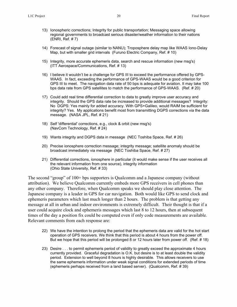
The second “group” of 100+ bps supporters is Qualcomm and a Japanese company (without attribution). We believe Qualcomm currently embeds more GPS receivers in cell phones than any other company. Therefore, when Qualcomm speaks we should play close attention. The Japanese company is a leader in GPS for car navigation. Both would like GPS to send clock and ephemeris parameters which last much longer than 2 hours. The problem is that getting any message at all in urban and indoor environments is extremely difficult. Their thought is that if a user could acquire clock and ephemeris messages which last 8 to 12 hours, then at subsequent times of the day a position fix could be computed even if only code measurements are available. Relevant comments from each response are:
22) We have the intention to prolong the period that the ephemeris data are valid for the hot start operation of GPS receivers. We think that this period is about 4 hours from the power off. But we hope that this period will be prolonged 8 or 12 hours later from power off. (Ref. # 18)
23) Desire . . . to permit ephemeris period of validity to greatly exceed the approximate 4 hours
currently provided. Graceful degradation is O.K. but desire is to at least double the validity period. Extension to well beyond 8 hours is highly desirable. This allows receivers to use the same ephemeris information under weak signal conditions for extended periods of time (ephemeris perhaps received from a land based server). (Qualcomm, Ref. # 39)

L1C Project 21 Final Report
The third group of 100+ bps supporters wants no additional messages at all. They want a higher data rate to minimize the time to first fix (TTFF) and also to minimize the time from first acquiring a “fresh” satellite (one for which there is no valid, stored clock and ephemeris data) before it can be used for navigation or for a snapshot position fix. Comments from this group include:
24) Faster TTFF will be desirable (Furuno Electric Company, Ref. # 11)
25) It would be useful to transmit ephemeris at a faster rate so the TTFF could be reduced (Garmin, Ref. # 12)
26) Quick-repeating ephemeris (ex. less than 15 seconds) and almanac (ex. less than 6.25
minutes). (Note contradictory input in comment 21, although with a similar objective.) (Ref. # 18.)
27) I hope no additional messages. I want to get ephemeris faster. My expectations for new
L1C signal are as follows: (1) Reduce effect of interference (2) Improve TTFF. (Panasonic Automotive Systems, Ref. # 35)
28) I have placed fast messaging as my preference to help with fast TTFF.
(University of New South Wales, Ref. # 50) Therefore, in contrast to the 41% of respondents who all want a 25 bps data rate to improve system performance in difficult signal conditions, the 41% who want 100+ bps are divided, some wanting extra integrity and accuracy messages, some wanting extra messages to extend the validity interval of the clock and ephemeris parameters, and some wanting no extra messages but a higher data rate to minimize TTFF and time to use a fresh satellite signal. Not to be left out, 11% of the respondents want to continue with the traditional rate of 50 bps. These respondents in general had no strong reason for selecting 50 bps. 5.2.5 Data Rate Analysis and Recommendation The previous section makes it clear there is a major conflict of interests about how best to enhance the messaging performance of L1C. We believe a simple assessment of these conflicts actually is the best assessment. Figure 5.4 shows that if we consider only those who expressed a preference and then arbitrarily split the group wanting 100+ bps into three equal subgroups: 15% for accuracy and integrity messages, 15% for longer lastransmission with no additional messasee there is no way to reconcile these expressed an opinion want 25 bps to m
Fig. 5.4 – Bit Rate Preference for Those Who Care
ting orbit and clock messages, and 15% for faster ges, then note that 12% would be happy with 50 bps, we minority positions. In contrast, 43% of those who ake the signal more robust and to enhance system

L1C Project 22 Final Report
performance under difficult signal conditions. Based on “winner take all”, 25 bps would be the obvious selection. More careful analysis shows this is to be a reasonable outcome. Take the case of flying toward an area for which the FAA has issued a NOTAM alerting aviators that GPS performance may be unreliable in that region. Let’s assume the GPS receiver will drop lock and stop providing navigation information 50 miles from the center of this region. With a bit rate of 25 bps, loss of message data and loss of lock will occur at about the same 50 mile radius. However, at 100 bps the message data would become unreliable over a 100 mile radius. It is unlikely a certified receiver would be allowed to continue giving navigation information without message reception even if the receiver were locked to the GPS signals and continued to provide pseudorange measurements. At 25 bps the area affected by message loss and by signal drop lock is about the same. At 100 bps the radius affected by message loss is twice as large and the area affected is four times as large. Although for different reasons, the same relative performance issues apply to navigation in forests, along tree-lined roads, and inside buildings. The penalty for this more robust message performance is that the time required to obtain clock and ephemeris parameters from each satellite is from 36 to 48 seconds as compared with 18 to 48 seconds with C/A today. The quickest time is worse but the longest time is the same. Because certified aircraft receivers now require receipt of two identical messages from a satellite before its signal can be used, the minimum time needed by an aviation receiver to obtain C/A ephemeris and clock data actually is 48 to 78 seconds. Because the modernized message on L1C will have a strong cyclic redundancy check (CRC) and will identify the specific satellite it describes, crosscorrelation problems are eliminated and we expect certified receivers will be allowed to begin using a satellite signal after receiving only one CRC-validated message. Therefore, for aviation, we compare 36 to 48 seconds using L1C at 25 bps with 48 to 78 seconds with C/A today. Not only are the message and drop lock thresholds approximately the same at 25 bps in areas with high levels of interference, the aviation TTFF would be faster with L1C than today. Integrity and DGPS Messaging One of our team members is Karl Kovach of ARINC who probably has more experience with GPS messaging issues than any other professional in the field. He was asked to comment on using GPS messaging for some of the desired high rate features. His responses are quoted in the following discussions. There are problems trying to use GPS messages for integrity and/or for differential GPS (DGPS). With respect to integrity messages, Karl stated: “the sense I have is that most folks are starting to realize that trying to turn GPS III into a clone of WAAS for integrity and DGPS is not such a smart idea. Really, if you think about it - - since WAAS can't meet the 5.2 second [time to alert] requirement with a real-time data link at 250 bps (500 sps), then why would anyone think GPS III can meet it with a real-time data link at 100 bps (200 sps)?” This same perspective is expressed by Professor Per Enge of Stanford University in response # 42 of Attachment 7.0. SBAS employs a ground station to uplink integrity and DGPS messages to a communication satellite which then re-broadcasts these messages at the GPS L1 frequency to users within its antenna coverage “footprint”. However, there are jurisdictional problems, at least for aviation

L1C Project 23 Final Report
navigation. No sovereign nation (or in the case of the EU, group of nations) is willing to relinquish control of aviation in its territory to another sovereign entity. It is unlikely other nations would allow GPS, under U.S. control, to define integrity within their territory. It also seems clear the U.S. Government will not allow other nations to control the signals GPS broadcasts over their sovereign territory. This would be a jurisdictional and logistics nightmare. It is far better for individual nations to use local means to provide integrity and DGPS messages. Karl Kovach continues: “For integrity, the idea that is starting to take hold is simply to prevent integrity failures right at the source. For satellites, that means a fail-safe clock system like [that] on the IIR birds. For the OCS, that means pre-validating the upload data before uplink. There is an old saying which is appropriate here: ‘An ounce of prevention is worth a pound of cure’.” Regarding DGPS messages, there are other problems. For example, the DGPS message structure is different for different applications. Single frequency DGPS has different requirements than dual frequency DGPS. Even if these differences can be bridged, local monitor stations would have to forward correction messages to the satellites, which requires either a much larger, worldwide, GPS ground monitor network or for the U.S. to accept and use measurements from international stations. Compared with local means of providing DGPS signals, this seems more cumbersome than it is worth. Furthermore, such a service would directly compete with commercial systems already in place. It also appears that in the GPS III era, dual frequency autonomous GPS navigation may approach one decimeter accuracy. For most applications, external DGPS will not be necessary. Therefore, it will be used only for quite specialized applications to achieve even better accuracy, and such very high accuracy and specialized applications are not logically supported by a global system. We conclude that not only is there disagreement about how to use a 100+ bps GPS data rate, it is cumbersome and impractical to use GPS for integrity and differential messages. Faster TTFF Two competing methods were proposed to improve TTFF. One was to transmit longer lasting orbit and clock data, and the other was to not transmit additional data but to transmit the required minimum orbit and clock data at a faster bit rate. The groups who wanted this capability were focused on GPS embedded in cell phones or on car navigation applications. The problem is real. Drive out of a city parking lot after a few hours and it often takes many blocks of driving before GPS begins to provide navigation. In some cases it is necessary to stop in an open area for awhile. Driving in obstructed areas can briefly interrupt the signal and thus prevent whole messages from being acquired. Even if the data were provided at a faster rate, that does not prevent brief outages which prevent reception of whole messages. Furthermore, some satellite signals may not be visible except when passing through an intersection, and this brief time is not adequate to receive a whole message.

L1C Project 24 Final Report
It would seem the best solution is to provide users in urban environments with an alternate way to obtain GPS orbit and clock parameters. We agree that orbit and clock information which is valid for 8 to 12 hours or more also would be very beneficial. However, urban environments are where other technologies are emerging which can provide alternate communication links. For example, wireless wideband Internet access is becoming more readily available. By the time L1C could be available on most GPS satellites (perhaps by 2020), such access will be common on cell phones. Automobiles are likely to be equipped with wireless Internet access as well, which could be used not only to provide long duration GPS orbit and clock parameters but also local traffic congestion reports and routing support. A commuter also could use a home Internet connection with a wireless link to the car in the garage to obtain traffic and orbit information in the morning before leaving for work. Long term orbits would still be valid on the commute home that evening. With the vast increase in number of users, there will be commercial incentives to make such navigation and traffic support functions readily available at very low marginal cost. Karl Kovach suggests there will be no objection for the GPS Control Segment to make long term orbit and clock parameters available over the Internet. The equivalent already is available from the Jet Propulsion Laboratory (JPL) and other computational centers associated with the International GPS Service (IGS). We conclude that not only is it impossible to agree that the best way to use a 100+ bps data rate is to enhance TTFF, we believe it is functionally better to solve this problem in a more elegant and effective way by using local communication services. Cell phones are communication devices, and the bandwidth of these links is getting faster. Wireless Internet access is proliferating rapidly, and this application could further increase the incentive. Not only will an external solution work better, it can provide other useful information as well, such as warnings about local traffic congestion and suggestions for alternate routing. 5.3 Expert Interview Signal Recommendations Based on analysis of responses from GPS experts in a wide range of specialties, this L1C project concludes:
1. It is technically feasible to add a modernized civil signal on the GPS L1 frequency.
2. There is a nearly universal desire for an additional, modernized L1 civil signal.
3. The modulation preference clearly is BOC(1,1) rather than BOC(5,1).
4. Although with less unanimity, the best choice of data rate is 25 bps. This optimizes signal robustness for all applications but leaves DGPS, integrity messaging, long duration orbit and clock parameters, and faster orbit and clock parameters to local communication services that are inherently better suited to this task.
5. The following additional tasks are recommended:

L1C Project 25 Final Report
Review this report and its conclusions with the respondents and other interested
parties to fully validate or, if necessary, slightly modify the conclusions Perform technical studies to determine how best to incorporate the L1C signal Review forward error correction options to determine if changing from the current
L2C and L5 standards would be worth the potential improvement in error rate Propose specific code generators and code lengths for each L1C signal component Review waveforms similar to BOC(1,1) which may give slightly better performance Prepare a top level signal description to enable the Interface Control Working Group
(ICWG) process to develop detailed specifications Interact with the GPS/Galileo interoperability working groups to optimize benefits for
the worldwide civil user population while protecting national security interests 6.0 Market Segment Signal Needs and User Feedback This section examines several key segments of the GPS market from the perspective of signal needs. At this time every market segment depends on the GPS C/A code, so in that sense the C/A code has proven to be adequate for all existing applications. However, when companies developed today’s products there were no signal options; they could use only the one available signal. GPS modernization will provide two other civil signals, L2C and L5, and GPS III now offers the opportunity to design a new civil signal at L1. Therefore, the present question is what new L1 signal characteristics will best serve the full spectrum of existing and future applications. Some have suggested that all civil signals should be considered as a package when developing a new L1 signal. In other words, GPS will provide a civil service consisting of at least three signals: C/A at 1575.46 MHz (L1), L2C at 1227.6 MHz (L2), and L5 at 1176.45 MHz (L5). Each of these not only are at different frequencies, they have three different modulation waveforms, two different data rates, and two different message formats. In addition, Galileo is expected to provide similar Open Service (OS) signals at L1 and at L5 (E5a). (Galileo also intends to provide other signals as well, but none of the others shares a frequency with GPS, and access to most could require a user fee. The U.S. Government has made it clear that all civil GPS signals will be provided free of charge to all users, worldwide. Therefore, when developing a new GPS signal it would be inappropriate to take into account anything but the free Galileo OS signals which overlay GPS.) Should L1C, therefore, be developed to enhance the overall package of already-planned GPS and the common OS Galileo signals? Our answer to the previous question is “no”. This is because the largest number of users, by a vast margin, is expected to use only one of the common GPS and Galileo frequencies. In most cases we think this will be L1, although L5 also may be selected for many single-frequency applications. The following section examines the reasons for this conclusion. In either case, if L1C is likely to be used widely for single-frequency navigation, such receivers must rely on that one signal for all its navigation information. It can’t take some data from one frequency, other information from a second frequency, etc. Therefore, L1C must be designed to support single frequency navigation applications and, in that sense, be able to function independently of all other GPS signals.

L1C Project 26 Final Report
On the other hand, it might be helpful for L1C to have somewhat different characteristics than L5 to give companies a broader range of choices when considering which signal to use for single frequency applications. 6.1 Single-Frequency Applications Dominate Some will find this assertion troubling. After all, won’t technology make dual-frequency receivers practical for all applications, and isn’t dual-frequency removal of ionospheric refraction error of vital interest to most users? We believe the answers are “no” and “no”. Until recently car navigation has been the largest GPS application. In the near future, if not already, embedded GPS in cell phones will be the largest application. Consider that, worldwide, between 400 and 500 million cell phones are sold annually. Expected trends are for cell phone sales to climb and for inclusion of GPS to increase. As a result, industry experts believe GPS will be available to a billion worldwide users within the next 15 years. Although the original impetus for GPS was to support the wireless E-911 service, other market forces are pushing the market toward greater use of GPS. For example, recent Nextel ads read: “WHERE TO TURN FOR DIRECTION. Nextel’s GPS-enabled phones get you there with audible turn-by-turn directions.” GPS offers wireless providers another competitive feature and another source of revenue. It offers subscribers additional safety, directions to and advice about services, a way to remember the way back to favorite places or to record the location of a photograph, and perhaps customers will allow merchants to alert them when near certain stores on an approved list. All of these require more continuous use of GPS. Car navigation is expected to be the second largest GPS application. There are many millions of car navigators in use today, and the number will grow dramatically over the next decade or two. When annual production quantities are numbered in the millions, or the hundreds of millions, the dominant consideration is minimum product cost to meet performance requirements. The pressure on embedded GPS makers is to lower the chip cost to well under a dollar, perhaps reaching 25 cents. A large fraction of the overall GPS cost, therefore, is the antenna and the RF bandpass filter, which are substantially less expensive for single frequency reception. In cell phones, the most important antenna function is revenue-producing communication, and communication performance is not being sacrificed to add today’s single frequency GPS much less to incorporate a more elaborate two-frequency antenna. When fractions of a penny count and when consumers don’t demand it, it’s almost inconceivable that dual frequency receivers will ever be used in high volume cell phones. The same cost pressures exist for car navigation, although with less emphasis, so far, to combine a GPS antenna with a cell phone antenna. If consumers demanded ionospheric refraction correction and were willing to pay for better GPS accuracy, manufacturers would be happy to supply the products. However, unless the improvement is free, as with SBAS (Satellite Based Augmentation System), this isn’t happening. SBAS provides differential and ionospheric correction signals at the L1 frequency, so the added cost to have this service in the GPS receiver is practically negligible. Other differential correction signals also are available, but they require an extra receiver, which consumers have shown no interest in buying. Better antennas and wider bandwidth receivers with improved

L1C Project 27 Final Report
signal processing can minimize multipath error, but suppliers continue to stress low cost rather than better accuracy. Japan has a network of differential correction stations which provide signals via sidetones on FM broadcast stations. Reception is included in the car radio at negligible extra expense, so the service is in wide use. Such systems also may provide traffic alerts to help navigation routing adapt to local traffic conditions. For the user, this is a low cost way not only to achieve better accuracy but also to obtain a potentially important routing benefit. The conclusion seems to be that although better accuracy may be desirable, manufacturers and consumers don’t perceive it as worth increasing GPS cost or complexity, especially if even better accuracy is available for free, such as with an SBAS signal. (The Wide Area Augmentation System, or WAAS, is the U.S. SBAS, and SBAS is automatically included in almost all current consumer products.) If traffic information plus differential GPS corrections can be broadcast locally, there also would be both a public and a private incentive to incorporate such signals in GPS car navigation products, especially because the consumer also obtains these benefits essentially for free. Therefore, we conclude that the vast majority of GPS applications will be for consumers and that consumers predominantly will use single frequency GPS receivers. Single frequency GPS receivers thus will vastly outnumber more complex receivers, and the resulting difference in production volume will further increase the cost differential. As a result, the L1C signal must be designed for stand-alone navigation service, providing all necessary information to its users. 6.2 Which will be the Single Frequency of Choice? Current plans limit the choice of which signal to use for single frequency applications to L1 and L5. This is because improved satellite geometry (more satellites) is an extremely valuable asset, especially in environments where signal blockage by terrain, trees, or buildings is a problem, and these are common problems for most consumer applications. Therefore the ability to use both Galileo and GPS satellites offers a benefit to the user which can’t be ignored. Previous paragraphs have established that the vast majority of consumer products will use only one frequency, and the EU is designing Galileo to transmit only two signals which overlap GPS frequencies, namely L1 and L5 (E5a). Therefore, these are the only two signals which will allow use of all GPS and Galileo satellites while retaining the simplicity of a single-frequency design. There are two key advantages to L5. It is expected to be the most powerful civil GPS and Galileo signal. The minimum received L5 power specification for GPS is between –154 and –154.9 dBW into a circularly polarized antenna. The equivalent L1 C/A code specification today is –158.5 dBW, or from 3.6 to 4.5 dB weaker. (Measurements show that transmitted C/A signals are 1 to 2 dB stronger than the specification, so the practical difference may be only 1.6 to 3.5 dB.) The proposed L1C signal could be specified to have a minimum signal of –155.5 dBW, or only 0.6 to 1.5 dB weaker than the L5 specification. Even so, signal power is extremely important and may drive the signal selection toward L5 for single frequency use. The second key L5 advantage is signal bandwidth, because it has a 10 MHz (actually 10.23 MHz) code clock rate. This provides 10 dB better rejection of narrowband in-band interference than the 1 MHz C/A code and 5.2 dB better rejection than the BOC(1,1) signal. These can be

L1C Project 28 Final Report
important for some applications and, along with more signal power, may drive design decisions toward L5. The case for L1 rests on three points. The first is the effect of the ionosphere on received signals. At certain latitudes, and especially during times of peak solar storms, scintillation causes signal fading and can cause loss of lock. The problem is more severe at lower frequencies, e.g., L5 versus L1. Probably more important, ionospheric refraction error is inversely proportional to the square of the signal center frequency. Therefore, L5 ionospheric errors always are 1.8 times worse than L1 errors. If the ionospheric error at L1 is 3 meters, at L5 it will be 5.4 meters. L1 provides better single frequency accuracy than L5, even when SBAS ionospheric corrections are applied. The second key point is the inverse of the L5 bandwidth advantage. The 10 MHz L5 code practically fills the allotted signal bandwidth. Therefore, it is important for the RF filter to be wide enough to accept most of the L5 signal energy but with sharp bandpass skirts to reject out of band interference. This type of filter requires more “poles” and thus is more expensive to manufacture. (Remember that we are talking about a penny of cost being important for consumer applications.) In contrast, the main spectral lobes of a BOC(1,1) signal occupy only the central ±2 MHz of the ±10 MHz allotted signal bandwidth. This gives designers the choice to use a wide bandwidth filter with sharp skirts for applications requiring maximum accuracy or, to minimize cost for consumer applications, to use a relatively narrow bandwidth filter with fewer poles and wider skirts. Current consumer GPS products typically use a narrow bandwidth filter to save cost even though better accuracy could be obtained with a wider filter and faster processing circuitry. Another result of the bandwidth difference between L1 and L5 is that by using a narrower bandwidth RF filter the consumer product can digitally process the signal with a lower clock rate. This may be an important difference for battery powered products such as cell phones. (Today, cell phone power is saved by shutting down the GPS receiver when not in use. Because the initial objective was only for E-911 positioning, GPS is used very seldom. In the future, however, people will begin to expect and to use more continuous navigation services, so concern for battery consumption will increase.) Consider also the wrist watch navigator, where power is even more limited. Better narrowband interference protection from the 10 MHz L5 code is countered at L1 in two ways. First, it is known that the L5 band contains more interference than the remarkably quiet L1 band. Narrowband interference of current L1 receivers is practically unknown. Second, by using a narrowband RF filter there is less bandwidth exposed to interference. In other words, the filter attenuates many interfering signals that otherwise would affect an equivalent signal in the L5 band. The final L1 advantage is experience. Many millions of L1 C/A receivers are in use around the world. Receiver companies and end users have vast experience with the L1 band. It will be many years before enough L5 and E5a signals are available to support a robust navigation service. During this time L1 use will continue to expand rapidly. Experience will favor the continued selection of L1 as the single-frequency signal of choice.

L1C Project 29 Final Report
Ultimately the market will determine whether L1 or L5 becomes the dominant single-frequency signal. We believe it will be L1. However, even if L5 becomes the ultimate signal of choice, it would be unacceptable to design L1C without the ability to optimally support single-frequency GPS navigation. 6.3 Market Segments In order to characterize market needs, we characterize the market segments as follows:
Table 6.1 – Primary Market Segments
Professional & Scientific
Commercial
Consumer
Land Marine Aviation
The “professional and scientific” column is intended to stress applications where very high accuracy is required. This includes GIS data collection, land survey, machine control, earthquake, volcano, and structure monitoring, and weather prediction. Although GIS data collection products typically require sub-meter accuracy, the others require accuracy of a centimeter or better. The “commercial” category represents products which are used by companies as a business tool. Such products include truck and taxicab tracking and routing systems, navigation systems for small commercial vessels to supertankers, and aircraft navigation systems for business aircraft to jetliners. By “consumer” products we mean items which are sold to individuals rather than companies. Such products range from GPS embedded in a cell phone to navigation systems for cars, boats, and airplanes. The following paragraphs discuss likely signal requirements for each major column of the table as well as for some of the rows, e.g., aviation. 6.3.1 Consumer Product Needs for a New Signal The most important driver for consumer products tends to be achieving the lowest possible cost to achieve competitive performance requirements. For navigation applications, better map displays and routing software are more important differentiators than improved GPS receiver characteristics. For embedded GPS, low power as well as low cost are the drivers. For these reasons, we expect most, although not all, consumer applications will use single-frequency receivers. Because satellite geometry and visibility are so vital to adequate performance, we also expect most consumer products to use both GPS and Galileo on a common frequency. The key exception to single frequency consumer products is likely to be navigation equipment for general aviation, where WAAS support of dual-frequency receivers will significantly improve available accuracy with integrity, availability, continuity, and coverage. These improvements will allow general aviation aircraft to make precision approaches to all approved airports without needing other equipment.

L1C Project 30 Final Report
Although the L1C waveform will be chosen by the Government, it seems likely that consumer companies would prefer BOC(1,1) over BOC(5,1). With its narrower bandwidth, BOC(1,1) gives companies the opportunity to choose between L5 for the advantages of a wide bandwidth signal or L1C for the reciprocal advantages of a narrower bandwidth signal. This is an important consideration for very low cost applications, but even general aviation companies probably would prefer BOC(1,1) to avoid any concern about tracking a sub-peak of the BOC(5,1) correlation function. The most contentious issue is data rate. Four nearly orthogonal needs have been defined. These are: (1) for a high data rate to provide additional accuracy and integrity messages, (2) for a high data rate to minimize the time needed to collect the clock and ephemeris messages and begin using a fresh satellite signal or to begin navigating (TTFF), (3) for a high data rate to provide messages with longer-lasting orbit and clock parameters, such as 8 to 12 hours, so subsequent position fixes don’t require reception of a new message, and (4) for a low data rate to maximize the chance of receiving any message at all in challenged signal environments. These clearly are conflicting requirements, and there is no way to favor one without hurting the others. We must seek a solution which provides the best possible performance to all users, and the key to this may be through other ways to deliver messages. The data-less or pilot carrier component of L1C is an advantage for all users. This permits receivers in challenged conditions to acquire and track signals at lower S/N levels than would be possible without a pilot carrier. This is an advantage for all applications, but especially for indoor use. 6.3.2 Aviation Signal Requirements Aviation users are facing a major transition and therefore a dilemma. Unlike other users, certification requirements for aircraft and equipment make it more expensive to upgrade a navigation receiver than simply buying a new product and plugging it in. Every certified aviation receiver today employs the single frequency C/A code. In the future there will be at least three and possibly four civil GPS signals. Galileo will provide signals at L1 and at L5 (E5a), so these two signals will give access both to GPS and to Galileo, practically doubling the number of visible satellites. Galileo also intends to have an E5b signal not only for navigation but also to send integrity data to aviators. Although of limited interest within the U.S., E5b may be mandated in Europe and could require a user charge. The aviation community recognizes that these major changes are coming, and it is understood that performance will be improved significantly. However, there is very little incentive to make any change until the new options and their advantages are clearly defined, the signals are specified, the services are nearly available, and certified equipment is available at a reasonable price. For example, although WAAS already has been commissioned for use in the U.S., very few certified receivers are available and very few are being installed. Owners don’t want to invest in a new receiver just to add single frequency WAAS when another replacement may be desired or required in a few years because of all the new options on the way.

L1C Project 31 Final Report
The FAA urged and sponsored development of the L5 signal. The main advantage of L5 for aviation is to permit dual-frequency navigation with both signals (L1 and L5) in Aeronautical Radio-Navigation Service (ARNS) bands. (L2C will be available several years sooner than L5, but it is not in an ARNS band.) Although L5 alone must support navigation if L1 is not available, its 80% larger ionospheric error makes it a significantly less desirable single-frequency signal than L1, even with SBAS corrections. When combined with L1 to eliminate ionospheric refraction errors, aviation performance, especially with SBAS, is greatly improved. (Dual frequency receivers with SBAS support are expected to provide the equivalent of Category I precision guidance.) Therefore, L1 will continue to be the most important signal for aviation, and development of L1C offers a chance to further improve performance. Some aviation experts have recommended a higher data rate on L1C so GPS can provide integrity and differential correction messages directly, thus eliminating the need for a separate SBAS signal. In contrast, other aviation experts want a very low data rate so L1C remains usable as close to areas for which the FAA has issued a NOTAM alerting aviators that GPS performance may be unreliable in that region. It is important to seek an answer which provides benefit to both points of view. Once again, resolving this conflict of objectives may have to rely on other data sources. 6.3.3 Professional and Scientific Signal Requirements High precision applications include Geographical Information System (GIS) data collection where half meter accuracy is needed, land survey where centimeter accuracy is required, and machine control where centimeter accuracy under harsh dynamic conditions is needed. Also included is monitoring of structures such as bridges and dams where sub-centimeter accuracy is desired. Finally, this same type of equipment is used for a variety of scientific applications such as volcano and earthquake monitoring, determination of polar motion and continental drift, and atmospheric observations for weather prediction. With the exception of GIS data collection, all of these applications require dual frequency carrier phase measurements. These are available today using C/A measurements on L1 with codeless or semi-codeless measurements of L2, aided by L1 tracking. A major improvement for these applications is on the way because, for the first time in GPS history, a civil code on L2 (L2C) will be provided. With this code, L2 measurements will be far more robust, and eventually the complex and expensive codeless and semi-codeless circuits no longer will be needed. When L5 becomes available from most satellites, it also will be incorporated. Three frequency receivers are expected to extend the range over which high precision measurements can be made and provide quicker results over conventional distances. These improvements also will be enhanced by access to both GPS and Galileo signals. Because Professional and Scientific receivers have access to all signals and all messages, and because the primary measurement is of carrier phase, there are no major concerns with any L1C signal option. The primary benefit will be the pilot carrier. Otherwise, there are no problems using BOC(1,1) or BOC(5,1), and with access to all messages there is no particular benefit to a higher or a lower data rate on L1C. The one exception is that accuracy is the most important

L1C Project 32 Final Report
consideration for this group. Anything that could be added to the message to further improve accuracy would be welcome. 6.4 User Interviews Section 4.4 outlined the process whereby user groups would be surveyed to determine their current use of and dependence on GPS and what improvements they would appreciate the most. The approach is documented in Attachment 8.0 and the results are documented in Attachment 8.0. The approach was to identify a potential benefit to users from each main technical improvement expected from L1C. Major established GPS user groups were identified by discipline or interest (see User Benefits Matrix in Table 6.2 below), and a priori assessments made of how L1C parameter choices might impact each user group positively. For these cases, an ‘X’ was assigned in this matrix, and an explanation of user potential benefits was created. During the interview process with users, these potential benefits were discussed and validated, and additional comments were elicited by the process.
Table 6.2 – Benefit of Each L1C Improvement to User Applications
In Section A of Attachment 8.0, the potential user benefits for each L1C performance enhancement are explained for the non-technical GPS user. Section B is the matrix above, and Section C contains an explanation and user response information for each of the major application areas given in the matrix. For each ‘X’ in the matrix, a description of the potential benefit for that user group is given in Attachment 8.0. In all cases, the users who were

L1C Project 33 Final Report
interviewed believed that modernizing L1C would be of positive benefit to them in their GPS applications. For example, all user groups clearly would benefit from reduced susceptibility to self-interference by adding L1C instead of simply boosting L1 C/A power levels. These user survey data also make it clear that, in particular, a more robust and powerful GPS L1C signal would be very welcome. The user interviews verified and strengthened our conclusion that L1C would be a valuable asset to GPS and should be implemented. 7.0 Conclusions and Recommendations We conclude that:
1. L1C is technically feasible, 2. The need for L1C is strongly supported by stakeholders, and
3. Experts prefer the following signal characteristics:
a. BOC(1,1) signal modulation b. 25 bps data rate
These three points reflect our primary findings on the first three L1C Project objectives, which were achieved on schedule and on budget, as described in detail within this report (including the documentation provided in the attachments). Recommendations to the IGEB are as follows:
1) Implement L1C as soon as feasible (it makes sense to complete GPS modernization across all three GPS frequency bands)
2) Retain C/A indefinitely, but implement L1C such that C/A can be discontinued in the
distant future without a negative impact on L1C users 3) Implement BOC(1,1) as the L1C modulation. (At one time the Galileo team was
evaluating subtle alternatives to BOC(1,1). If a better modulation is found which meets the EU/US agreements on signal compatibility, the U.S. should be prepared to implement it instead of BOC(1,1). However, such a replacement would have to be studied very carefully, justified thoroughly, and is very unlikely.)
4) Implement L1C with a data rate of 25 bps and with no additional messages. This yields
the greatest global benefit by making the signal more robust for all users without sacrificing robustness for the sake of a particular set of users. Therefore, DGPS signals, integrity messages, long duration orbit and clock parameters, and faster orbit and clock parameters should be provided by local or regional communication services which are inherently better suited to these tasks and also may include added value information.
The fourth L1C Project objective, to define the detailed signal specification for L1C, has not been achieved. This work should be done soon, however, in preparation for GPS III acquisition

L1C Project 34 Final Report
(e.g., CDD and ICWG processes) and for the next steps in international GNSS cooperation on system interoperability with Galileo and QZSS. We consider this forthcoming technical work to be best addressed by the technical team that has molded L1C up to this point, and this report contains our recommendations for that future work (in the Executive Summary and Section 5.3). We stand ready to continue, resources permitting, and of course pending decisions of the IGEB. 8.0 Acknowledgements: We greatly appreciate the ideas and time contributed by all questionnaire respondents, and the major in-kind support of all corporations and agencies whose employees participated. We especially acknowledge the JGPSC in Japan and the DOTARS group in Australia for their assistance in distributing and encouraging feedback throughout the duration of the L1C Project. GPS JPO officers serving under Col Rick Reaser, former Chief GPS Engineer, have guided and provided their input and ideas to the L1C Project. Initially, Maj Pat Harrington and Capt Reginald Victoria were involved in framing and successfully proposing the project. Capt Bryan Titus then brought the L1C Project through its main phases of technical development, while simultaneously working with the international GNSS community to ensure interoperability between GPS and Galileo. Lt Jason Taylor assisted by effectively presenting the L1C Project at the ANC Navigation Systems Panel in Canberra, Australia. During final stages of the project, Col(S) Mark Crews, LtCol Douglas Brown and Capt Dominic Alcocer have seen everything through to completion. This project was made possible through the devoted and talented engineers and GPS experts working as contractors for the government. In particular, Mr. Tom Stansell played a crucial role in all aspects of design and strategy, as well as technical interviewing, throughout the duration of the project, and he wrote major sections of this report. Along with Mr. Stansell, Charlie Cahn, Rich Keegan, Karl Kovach, Chris Hegarty, Phil Dafesh, and John Betz also participated significantly in technical deliberations over signal design considerations. Joe Dorfler led the collection of information from the GPS user community through the user benefits feedback approach and by accessing previously conducted reports and information. Members of the Aerospace GPS III group helped in various capacities (Clark, Yowell, Jamison, Raghavan, Cooper and others), and we appreciate their support and the information they provided. We appreciate the reviews provided by Bill Leith and Nancy King of USGS, as well as the support of Lucy Jones and Bill Ellsworth of the USGS National Earthquake Program. Finally, last but certainly not least, we are also especially grateful for the support of Larry Hothem (IGEB SSG member for DOI) and Dave Turner (Director, IGEB Executive Secretariat), whose guidance at many points along the way, from initiation to completion, made this project possible.

L1C FINAL REPORT
TABLE OF ATTACHMENTS
A-1.0: L1C Initial Presentation at CGSIC; Portland, Oregon; September 8, 2003 ...........A 2A-1.1: Presentation and Questionnaire Provided at NAVCEN Booth
during ION GPS-2003............................................................................ A 13A-1.2: GPS World article on L1C Project (October 2003 issue) ........................ A 18
A-2.0: L1C Presentation at GPS System Engineering Forum (GSEF); Los Angeles,California; October 28-29, 2003 ........................................................................ A 19
A-3.0: L1C Paper presented at International Civil Aviation Organization (ICAO) - AirNavigation Conference (ANC), Navigation Systems Panel (NSP); Canberra,Australia; November 11, 2003 ........................................................................... A 44A-3.1: L1C ‘flimsy’ for ICAO ANC NSP feedback .......................................... A 48A-3.2: ICAO Contracting States listing ............................................................. A 54
A-4.0: L1C Presentation at International GPS Service (IGS) 10th Annual Meeting; Berne,Switzerland; March 3, 2004 ............................................................................... A 59A-4.1: L1C Poster – presented at IGS Meeting.................................................. A 74
A-5.0: L1C Presentation (Parts I & II) at IEEE PLANS; Monterey, California; April 28,2004 .................................................................................................................. A 75
A-6.0: Annotated L1C Technical Interview Presentation ............................................ A 108A-6.1: Questionnaire Used for Experts Survey................................................ A 134
A-7.0: L1C Technical Questionnaire Responses (55 responses included).................... A 136
A-8.0: Civil User Benefits .......................................................................................... A 347A-8.1: User Group Guidelines......................................................................... A 392
A-9.0: Economic Benefits........................................................................................... A 395
A1 of 406

U.S. Department of the InteriorU.S. Geological Survey
1
L1 Modernization Project (L1C)
CGSIC 42nd Meeting
Portland, Oregon; September 8, 2003
Ken Hudnut, Ph.D. Lt Bryan TitusProject Manager Navstar GPS JPO, Co-LeadGeophysicist, USGS Sat. Nav. Engineer, USAF
A2 of 406

2
Purpose
To solicit comments from civil and other GPSstakeholders about:
whether or not a modernized GPS L1 civil signal should beadded - and, if so -
what types of modernization would be most valuable, andwhy
The U.S. Government has not yet determined whethera modernized GPS L1 civil signal should be added
3 of 406

3
Why Modernize? L1 C/A is Excellent
L1 C/A works well; it supports millions of users Accuracy is astounding
Absolute accuracy is a few meters (good for most users) Differential navigation can give sub-meter accuracy Surveyors and scientists rely upon sub-centimeter
differential results
Interference is minimal It’s being used for safety-of-life navigation
Why consider changing anything so successful? “If it isn’t broken, why fix it”… there’s room for improvement
4 of 406

4
What are Opportunities for Improvement?
Any of the longer-coded L1C options would be lesssusceptible to narrowband interference than L1 (C/A)
Could improve cross-correlation properties: Improve indoor or wooded area use Increase number of satellites and code signal power without
causing unacceptable self-interference Improve receiver signal acquisition threshold
Navigation message could contain more: Precision, flexibility, and forward error correction (FEC)
Signal tracking and data demodulation thresholds(robustness) would be better with a modernized signal
GPS III schedule presents an opportunity -requirements need to go into a CDD by Aug. 2004
5 of 406

5
Proposed Objectives
Compatible signal for legacy C/A receivers Continue to provide the C/A code
Minimize added noise for C/A receivers
New signals with better performance than C/A Better correlation properties (longer codes)
More signal power and better threshold tracking Improved performance indoors and under foliage
Improved message structure, precision, etc.
Improved narrowband interference protection
6 of 406

6
L1C Data Rate Tradeoff
L1C modernized data presumably will besimilar to or the same as for L2C and L5 Forward error correction (FEC) also will be used
Some data rate options: 25 bps (L2C) provides data in challenged
situations Urban canyons, indoors, in wooded areas
50 bps (L5) same as C/A now 100 bps would allow additional messages (e.g.,
integrity warnings)
What is best for your applications?
7 of 406
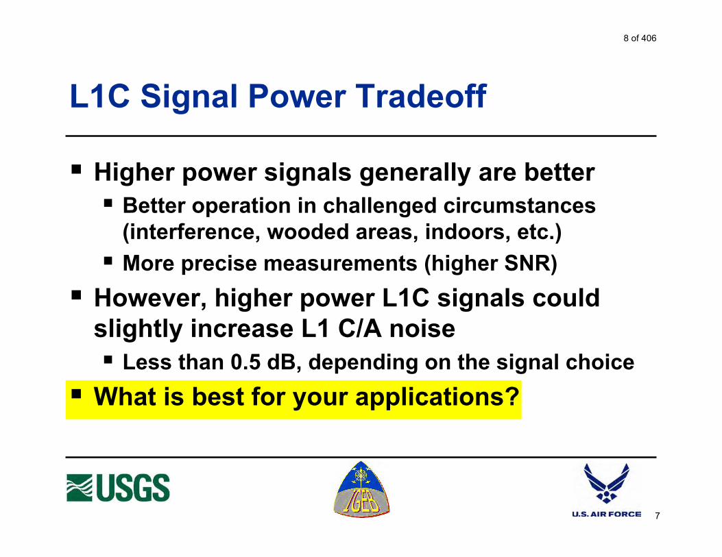
7
L1C Signal Power Tradeoff
Higher power signals generally are better Better operation in challenged circumstances
(interference, wooded areas, indoors, etc.)
More precise measurements (higher SNR)
However, higher power L1C signals couldslightly increase L1 C/A noise Less than 0.5 dB, depending on the signal choice
What is best for your applications?
8 of 406

8
L1C Code Length Tradeoff
The C/A code length is 1,023 chips (short)
Modernized codes are at least 10 times longer
Longer codes have major advantages: Eliminate cross-satellite interference
Reduce effect of narrowband interference
Enable more and more powerful satellite signals
But, acquisition time (per correlator) is longer Technology now permits thousands of correlators
What is best for your applications?
9 of 406

9
Adding L1C Messages - Which Ones?
GPS messages are only for navigation
Added value messages might provide: Integrity warnings of “bad” satellite signals or
weather, rescue, or other NAV-related messages
What is the best integrity source ? Ground signals, GEO satellites, RAIM, or GPS ?
With GPS plus other GNSS, is RAIM sufficient ?
What is best for your applications?
10 of 406

10
L1C Almanac & Ephemeris Precision
C/A ephemeris precision is about 1 meter
L1C ephemeris may have 1 cm precision
Is this of any benefit for your applications?
L1C “compact almanac” may be less precisethan C/A to cover more satellites faster
Is this change desirable or not?
Note: almanac contains coarse orbit data, broadcast by each SV for allSV’s, whereas ephemeris contains precise data broadcast by each SV foronly its own orbit & clock parameters
11 of 406
11
Your Reaction to L1C Modernization
Do you favor L1 civil signal modernization?
What are your concerns?
What are your desires?
Why? Please fill out the questionnaire
12 of 406

1
L1 Modernization Project (L1C) ION GPS/GNSS 2003
Portland, Oregon; September 10-12, 2003
Purpose
To solicit comments from civil and other GPS stakeholders about: Whether or not a modernized GPS L1 civil signal
should be added - and, if so -
What types of modernization would be most valuable, and why
The U.S. Government has not yet determined whether a modernized GPS L1 civil signal should be added
Why Modernize? L1 C/A is Excellent
L1 C/A works well; it supports millions of users
Accuracy is astounding Absolute accuracy is a few meters (good for most
users)
Differential navigation can give sub-meter accuracy
Surveyors and scientists rely upon sub-centimeter differential results
Interference is minimal
It’s being used for safety-of-life navigation
Why consider changing anything so successful?
“If it isn’t broken, why fix it” (there’s room for improvement)
Comments
A13 of 406

2
What are Opportunities for Improvement?
Any of the longer-coded L1C options would be less susceptible to narrowband interference than L1 (C/A)
Could improve cross-correlation properties: Improve indoor or wooded area use
Increase number of satellites and code signal power without causing unacceptable self-interference
Improve receiver signal acquisition threshold
Navigation message could contain more: Precision, flexibility, with forward error correction (FEC)
Signal tracking and data demodulation thresholds (robustness) would be better with a modernized signal
GPS III schedule presents an opportunity - requirements need to go into a CDD by Aug. 2004
Comments
Proposed Objectives
Compatible signal for legacy C/A receivers Continue to provide the C/A code
Minimize added noise for C/A receivers
New signals with better performance than C/A Better correlation properties (longer codes)
More signal power and better threshold tracking
Improved performance indoors and under foliage
Improved message structure, precision, etc.
Improved narrowband interference protection
Comments
14 of 406

3
L1C Data Rate Tradeoff
L1C modernized data presumably will be similar to or the same as for L2C and L5 Forward error correction (FEC) also will be used
Some data rate options: 25 bps (L2C) provides data in challenged situations
Urban canyons, indoors, in wooded areas
50 bps (L5) same as C/A now
100 bps would allow additional messages (e.g., integrity warnings)
What is best for your applications?
Response Rank: 1 = best Importance: 10 = very important 5 = moderate 0 = not important
Data Rate
Your Rank
Import
25 bps 50 bps 100 bps
L1C Signal Power Tradeoff
Higher power signals generally are better Better operation in challenged circumstances
(interference, wooded areas, indoors, etc..)
More precise measurements (higher SNR)
However, higher power L1C signals could slightly increase L1 C/A noise Less than 0.5 dB, depending on the signal choice
What is best for your applications?
Response Increase Signal Power:
Yes or No Comment:
L1C Code Length Tradeoff
The C/A code length is 1,023 chips (short)
Modernized codes are at least 10 times longer
Longer codes have major advantages: Eliminate cross-satellite interference
Reduce effect of narrowband interference
Enable more and more powerful satellite signals
But, acquisition time (per correlator) is longer Technology now permits thousands of correlators
What is best for your applications?
Response The L1C code normally used for signal acquisition should be:
10,230 chips
20,460 chips
Longer
Comment:
15 of 406

4
Adding L1C Messages – Which Ones?
GPS messages are only for navigation
Added value messages might provide: Integrity warnings of “bad” satellite signals or weather,
rescue, or other NAV-related messages
What is the best integrity source ? Ground signals, GEO satellites, RAIM, or GPS ?
With GPS plus Galileo, is RAIM sufficient ?
What is best for your applications?
Response Should the GPS data rate be increased to provide additional messages? Integrity: Yes No DGPS: Yes No Other: Yes No With GPS+Galileo, would RAIM be sufficient for integrity? Yes No
L1C Almanac & Ephemeris Precision
C/A ephemeris precision is about 1 meter
L1C ephemeris may have 1 cm precision
Is this of any benefit for your applications?
L1C “compact almanac” may be less precise than C/A to cover more satellites faster
Is this change desirable or not?
Response Would increased precision of the GPS ephemeris be valuable?
Yes No Would decreased precision of the almanac to provide more satellites quicker be valuable?
Yes No
Your Reaction to L1C Modernization
Do you favor L1 civil signal modernization?
What are your concerns?
What are your desires?
Why?
Reaction Favor L1 Modernization?
Yes No
16 of 406

5
Respond to one of the following:
E-mail: [email protected] FAX: 626-583-7827 Mail: L1C GPS, 525 South Wilson Ave., Pasadena, CA 91106-3212 Your Printed Name: Title or Position: Organization: Contact Information: Additional Comments:
17 of 406

Attachment 1.2: GPS World article on L1C Project (October 2003)
A18 of 406

U.S. Department of the InteriorU.S. Geological Survey
1
IGEB L1C Stewardship Project
GSEF – October 28-29, 2003
Program Considerations
Dr. Ken Hudnut, USGS
1Lt. Bryan Titus, GPS JPO
∞
A 19 of 406

2
IGEB L1C Stewardship Project
Project funded at $355K (IGEB memo July, 2003)
Co-chaired1Lt. Bryan Titus, GPS JPO
Dr. Ken Hudnut, USGS, Pasadena
Funding split $120K to JPO; $235K to USGS (MIPR dated 8/15/03; performance period 8/19/03-8/19/04)
Coordinated and cooperative activities
20 of 406
3
CGSIC/ION in Portland and IFOR
Hudnut presentation at CGSIC, Portland (9/8/03)
‘Civil Input on Future GNSS Signals’ issues panel, chaired by Hank Skalski (on CGSIC www)
Feedback and discussion during panel Q&A
Covered in October issue of GPS World (pg. 14)
NAVCEN booth at ION conference (9/10-12/03)
Slide presentation on laptop, one-on-one discussions, and ~ 60 questionnaires distributed
Civil IFOR presentation (9/23/03)
Larry Hothem, DOI/USGS
21 of 406

4
Feedback and Lessons Learned
FeedbackFour completed forms and three ‘free-form’ e-mail comments (most responses from technically inclined NASA and FAA employees/contractors)
Lessons have been learned – we are now redirecting our survey efforts
Low response rate from general questionnaireThere is definite interest in the GPS communityOutreach must be more direct and “personal”
22 of 406

5
L1C Technical and Strategy Meeting
Four sessions on 8-9 October at the JPO1. Navwar issues (classified) 2. Code structure and interference issues3. Message structure discussions4. Application advantages and outreach planning
ParticipantsChaired by Titus and Hudnut Included Betz, Cahn, Dafesh, Dorfler, Hegarty, Keegan, Kovach, Stansell, and Taylor
L1C benefits by user group being compiled
23 of 406

6
Next Steps
Prepare two types of surveyConduct surveys, domestic and internationalConsolidate the survey resultsUpdate the technical approach detailsPrepare final IGEB report, including:
Process descriptionSurvey results and cost estimatesPolicy recommendations Signal design recommendations
If a new signal is proposed
24 of 406

U.S. Department of the InteriorU.S. Geological Survey
7
IGEB L1C Stewardship Project
GSEF – October 28-29, 2003
Program Considerations
Dr. Ken Hudnut, USGS
1Lt. Bryan Titus, GPS JPO ∞
25 of 406

8
Technical Considerations
L1C technical meeting at JPO on Oct. 8 – 9Compatibility with US/Allied security
Backward compatibility with legacy C/A receivers
Signal design
Message options
Technical trade-offs for user benefits
26 of 406

9
US/Allied Security Compatibility
Classified session on 8 Oct. Navwar scenario and impacts were presented to technical experts
Group agreed there are three viable modulations
BPSK-R(2)
BOC(1,1)
BOC(5,1)
Other modulations will not be considered
27 of 406

10
C/A Legacy Compatibility
Any new GPS L1 signal must be RF compatible with legacy C/A receivers
Previous experience with M code and Galileo produced useful analysis tools
US/EU agreed Assumptions Document
US agreed Methodology for Analysis of GNSS Interference Effects
Considered scenarios with and without Galileo OS
28 of 406

11
Increased C/A Headroom
Prior to January of 2003, the minimum specified C/A signal power was –160 dBW
Worst case calculations show YMCA interference degrades received C/N0 to 31.2 dB-Hz
Minimum C/A signal power specificationincreased to –158.5 dBW to give headroom for new GPS and Galileo signals
Releasing JPO margin raises C/N0 to 32.7 dB-Hz
The effect of new GPS and Galileo signals is dependent on modulation and signal power
29 of 406

12
Analysis assumes GPS L1C and Galileo OS use the same BOC(1,1) modulation
Three scenarios are consideredYMCA only
(a) Today, (b) Better power control, (c) Triple the min. C/A power
L1C or OS (At 3 dB more min power than min C/A)
L1C and OS (Each 3 dB more min power than min C/A)
Power control in satellites limits the max interfering C/A, L1C, and OS power levels
C/A Legacy Compatibility Analysis
30 of 406

13
C/A Compatibility Analysis Results
YMCA is with C/A signals only, no L1C, no Galileo
L1C and OS results assume BOC(1,1)
Increasing C/A power x3 yields only x2 result
BOC(1,1) w/ power control is better for C/A than now
The BOC(1,1) signal power is twice the C/A power
31 of 406

14
L1C Signal Design
Minimum L1C Signal Power = –155.5 dBWTwice the minimum C/A power
Center frequency = 1575.42 MHz
Modulation: BPSK(2), BOC(1,1), or BOC(5,1)
Components: data and data-less channelsTracking sensitivity 6 dB better than C/A channel
FEC gives 5 dB of data threshold improvement
32 of 406
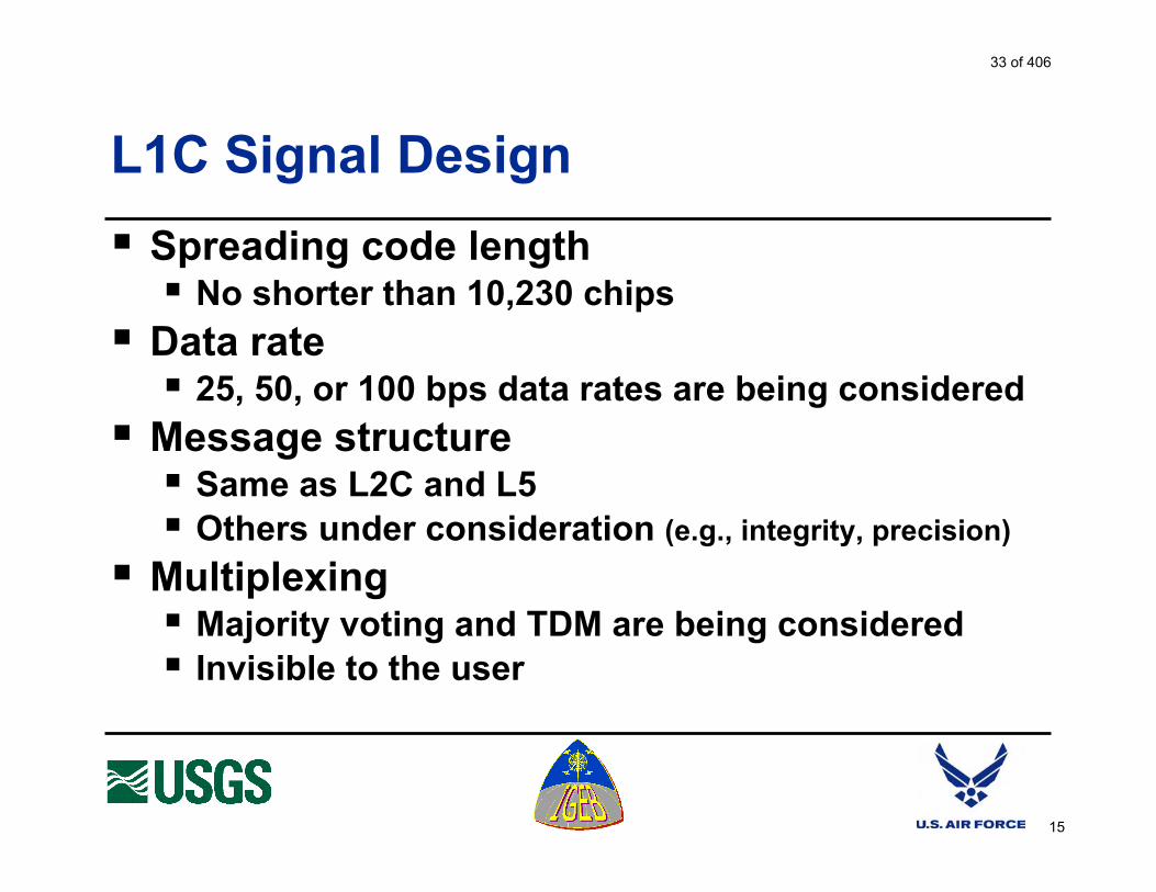
15
L1C Signal Design
Spreading code lengthNo shorter than 10,230 chips
Data rate 25, 50, or 100 bps data rates are being considered
Message structureSame as L2C and L5Others under consideration (e.g., integrity, precision)
MultiplexingMajority voting and TDM are being consideredInvisible to the user
33 of 406

16
Requirements Surveys
Review of prior studies conducted for GPS III
Two survey methods will be usedUser surveys based on L1C benefits
15 user groups identified (next slide)
Expert surveys based on L1C design choicesGovernment agencies
GPS manufacturers
GPS service providers
University GPS faculty
GPS industry experts
ION section meetings
34 of 406

17
User Trade-offs and Benefits
Fifteen user groups have been identified
Location based services
Scientific
Aviation
Agriculture
Surface transportation
Mining and Construction
Surveying/Civil engineering
Public safety
Timing
Rail
Recreation
Space
Environment
Maritime
Security
35 of 406

18
User Technical Trade-offs and Benefits
Each user group is assigned a team member
Face to face meetings/interviews with representatives from each user group
A “checklist” of items will be covered
L1C user benefits will be explained e.g.: Increased robustness to interference
e.g.: Improved ability to acquire and track indoors
Requirements and preferences will be gathered from the user community
36 of 406

19
Compilation of User Requirements
Information gathered in the meeting/interview phase will be compiled and compared
Plan to have statistically significant input from the GPS user community
Signal recommendation will be the result of the users’ input
37 of 406

20
Expert Survey Technique
?
TripleMinimum
C/A Power
Add ModernSignal at
2X MinimumC/A Power
?
BOC(5,1)
BOC(1,1)
BPSK(2)
?
100 bps orfaster
50 bps
25 bps
What NewMessages?
Experts asked to help choose the best path to modernization for their applications,
define applications, and explain why
38 of 406

21
Conclusions
Preparation is well underway
Expect to submit final report by Sept., ‘04
Budget should be sufficient
39 of 406

22
Backup Slides
40 of 406

23
C/A Signal Power Measurements
1.5 dB of JPO margin
was released
Raising the minimum specifiedC/N0 from 31.2 dB-Hz
to 32.7 dB-Hz
41 of 406

24
GPS III with IIF Antenna Pattern
42 of 406

25
GPS III with IIR-M Antenna Pattern
43 of 406

Attachment 3.0: L1C Paper: ANC Canberra – ICAO Navigation Systems Panel
NSP/WP/
NAVIGATION SYSTEMS PANEL WORKING GROUP MEETING
Canberra, Australia
Agenda Item XX
GLOBAL POSITIONING SYSTEM CIVIL FREQUENCY (L1)MODERNIZATION OPPORTUNITY
(Presented by the United States of America)
SUMMARY
The Global Positioning System (GPS) provides a solid foundation forenhancing CNS/ATM systems and services. Programs are underwayto add additional GPS civil frequencies (L2C and L5) and upgrade theground control network. There is a unique and exciting opportunity toadd a modernized civil signal to the L1 frequency to further improveGPS civil services.
This paper provides a brief overview of the L1 modernizationopportunity, technical examples/benefits of modernization, and aspecific point of contact for Meeting attendees and other userrepresentatives to enable them to provide direct information to thepersonnel responsible for L1 modernization.
1. INTRODUCTION
1.1 Global Navigation Satellite Systems (GNSS) signals and services are progressivelybecoming a critical element for the modernization of global communications, navigation,surveillance and air traffic management (CNS/ATM) infrastructures.
Assessments in recent years, such as those made at the 1995 SpecialCommunications/Operations Divisional Meeting, have suggested that GNSS-basedoperations may not reach their full potential until additional civil signals or core satelliteconstellations are available.
A44 of 406
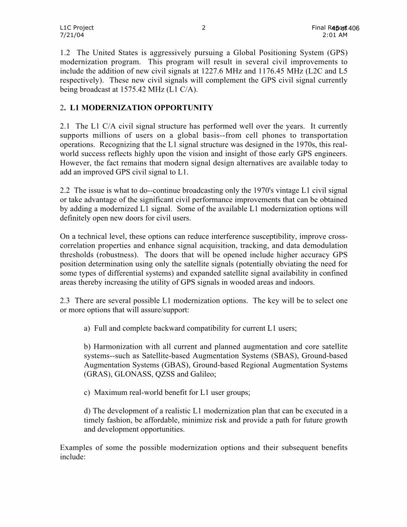
L1C Project 2 Final Report7/21/04 2:01 AM
1.2 The United States is aggressively pursuing a Global Positioning System (GPS)modernization program. This program will result in several civil improvements toinclude the addition of new civil signals at 1227.6 MHz and 1176.45 MHz (L2C and L5respectively). These new civil signals will complement the GPS civil signal currentlybeing broadcast at 1575.42 MHz (L1 C/A).
2. L1 MODERNIZATION OPPORTUNITY
2.1 The L1 C/A civil signal structure has performed well over the years. It currentlysupports millions of users on a global basis--from cell phones to transportationoperations. Recognizing that the L1 signal structure was designed in the 1970s, this real-world success reflects highly upon the vision and insight of those early GPS engineers.However, the fact remains that modern signal design alternatives are available today toadd an improved GPS civil signal to L1.
2.2 The issue is what to do--continue broadcasting only the 1970's vintage L1 civil signalor take advantage of the significant civil performance improvements that can be obtainedby adding a modernized L1 signal. Some of the available L1 modernization options willdefinitely open new doors for civil users.
On a technical level, these options can reduce interference susceptibility, improve cross-correlation properties and enhance signal acquisition, tracking, and data demodulationthresholds (robustness). The doors that will be opened include higher accuracy GPSposition determination using only the satellite signals (potentially obviating the need forsome types of differential systems) and expanded satellite signal availability in confinedareas thereby increasing the utility of GPS signals in wooded areas and indoors.
2.3 There are several possible L1 modernization options. The key will be to select oneor more options that will assure/support:
a) Full and complete backward compatibility for current L1 users;
b) Harmonization with all current and planned augmentation and core satellitesystems--such as Satellite-based Augmentation Systems (SBAS), Ground-basedAugmentation Systems (GBAS), Ground-based Regional Augmentation Systems(GRAS), GLONASS, QZSS and Galileo;
c) Maximum real-world benefit for L1 user groups;
d) The development of a realistic L1 modernization plan that can be executed in atimely fashion, be affordable, minimize risk and provide a path for future growthand development opportunities.
Examples of some the possible modernization options and their subsequent benefitsinclude:
45 of 406

L1C Project 3 Final Report7/21/04 2:01 AM
a) A different data rate for this new L1 civil signal from the current 50 bps rate. Benefitsfrom a slower data rate (25 bps) include an improved ability to obtain the satellitemessage inside and under cover, resulting in better signal acquisition in environmentssuch as heavily forested areas. Benefits from an upward adjustment (100 bps) couldinclude an opportunity to add additional information, such as an integrity message.
b) Signal Waveform modernization (e.g. BOC (1,1), (5,1), BPSK (2)) will significantlyimprove performance in interference environments and improve receiver accuracy.
c) Increased power levels (-158.5 to -155.5 dbW) will provide better signal acquisitionand tracking, and better coverage as a result of greater signal availability.
d) Longer code length (recognizing that 10230 will be the minimum length) will reduceself-interference and increase resistance to both intentional and unintentional narrowband interference and jamming (e.g. VHF transmitters).
e) The addition of error corrections (FEC Rate _, k=7 or better) will enable the user toobtain navigation data at much lower power levels; _ or less compared to the current C/Aperformance.
f) Modernization of the message content (e.g. similar to L5 and L2C with the possibleaddition of integrity, authentication, over the air NANUS, additional ionospherecorrection terms, etc.) will provide better navigation performance in terms of positionaccuracy, integrity and timing.
2.4 One of the first challenges will be to document service improvements that are desiredby the myriad of domestic and international L1 users. The planned approach will be toobtain inputs from a cross-section of L1 users, such as government organizations,manufacturers, and end-state users.
After compiling the data, it will be analyzed and categorized according to desired end-state improvements and the user group/direct benefit of the improvement, such as: RailTransportation--better signal acquisition and tracking in heavily forested areas.
The second challenge will be to estimate the real-world value of the end-stateimprovement. Given there is a clear understanding of the direct user benefit, it seemsreasonable to assume that the benefit will be of some value.
Current thinking is that there are fundamentally two broad classes for determining"value". The first and most important is the inherent safety related value. Measuring thevalue of safety is difficult if not impossible to reasonably determine for some usergroups. For others, there reportedly are methods for measuring the "value" of safetyimprovements.
The second class of benefits are those that likely can be estimated by a majority of theuser groups in terms of tangible resources. For instance, if L1 were modernized to enable
46 of 406

L1C Project 4 Final Report7/21/04 2:01 AM
the production of GNSS receivers at a lower cost, then one should be able to reasonablydetermine the cost savings, or the potential value of this L1 modernization option.
For these reasons, the US Interagency GPS Executive Board (IGEB) has approved andfunded an effort led by the United States Geological Survey and Department of DefenseGlobal Positioning System Joint Program Office to interact with domestic andinternational user groups for the purpose of assuring the broadest range of information isobtained to support the best L1 modernization decisions.
3. CONCLUSION
3.1 The Panel members and meeting attendees are encouraged to participate in the L1modernization opportunity by contacting Lt. Jason Taylor, Chief International GPSSigna l Requ i r emen t s , Te l ephone : (310) 363-3259 , E -ma i l :[email protected] and providing information regarding desired L1 serviceimprovements and subsequent benefits. Inquiries may also be addressed to the projectemail address at [email protected]. Additionally, all are invited to widely distributethis paper to colleagues and user groups with a recommendation to make contact and beinvolved in shaping the L1 future.
47 of 406

NAVIGATION SYSTEMS PANEL WORKING GROUP MEETINGCanberra, Australia
November 10-21, 2003
Questionnaire to provide a common point of reference for Panel input forL1C modernization.
The US has an opportunity to provide a modernized signal at L1 improving civilperformance. It is also technically possible to improve the signal withoutjeopardizing current L1 C/A civil uses--assuring full backward compatibility.
Attached are the range of potential L1C modernization improvements underconsideration, possible benefits, and explanations as to why this L1Cimprovement can provide a benefit.
Before making a decision whether or not/how to proceed with L1Cmodernization, we would like to determine and document if Aviation wouldactually obtain real-world benefits from a modernized L1C signal.
Hence, we would appreciate receiving your responses to the followingpoints/questions:
1. Based on your knowledge and personal experience could you highlight someof the ways GPS is being used today by Aviation other than those already listedin the SARPs.
2. One L1C modernization option, which may benefit the Aviation community, isgreater resistance to radio frequency interference (both intentional andunintentional) thereby improving the overall navigation performance and reliabilityfor both manned and unmanned aircraft/vehicles.
• Do you believe such a modernization will benefit the Aviation community?
• If it is a benefit, what do you think the benefit is “worth”, in terms of money,time saved, degree of safety improvement, operational savings—wouldappreciate any type of measure we can use to establish the benefit value.
• Approximately how many Aviation community users do you think willbenefit from these suggested L1C modernization improvements?
3. What other L1C modernization options—based on the attached list—do youthink will benefit Aviation users? For each option, please provide the specific
A48 of 406

benefit, the “worth” of the benefit, and how many Aviation users will realize thebenefit.
4. An alternative option may be to simply increase the transmitted power of theL1 C/A-code power (e.g., by 4 dB or 5 dB). What do you think of this option?
5. Finally, based on your knowledge and Aviation experience, how rapidly doyou think GPS use will grow over the next 5-10 years?
Thank You!!
49 of 406

L1CImprovement
⇒
Application⇓
LowerSignal
Thresholdsfor
Navigation(Power &DatalessChannel)
More RobustAutonomousNavigation
(Power, FEC& Data Rate)
LessSusceptible
toInterference
(Power &Code
Structure)
HigherDynamicsTracking
(Power andDatalessChannel)
Reduced Cross-correlation
(LongerSpreading
Codes)
ImprovedAccuracy(Increased
signalbandwidth)
Location BasedServices X X X X X
Scientific X X X
Aviation X X
Agriculture X X X X
SurfaceTransportation
X X X X X
Mining &Construction
X X X X X
Surveying/CivilEngineering
X X X X
Public Safety X X X X X
Timing X X
Rail X X X X
Recreation X X X X X
Space X X
Environment X X X
Maritime X X X X
Security X X X X X
50 of 406

L1C Improvement User Benefit Explanation
Lower Signal Thresholds forNavigation
(Power & Dataless Channel)
The user will be more likely to navigate(a) in difficult signal conditions, such
as in a forest, in a city, inside abuilding, on a tree lined road, etc., i.e.,where GPS signals are attenuated, as
well as (b) in the presence of GPSradio interference.
A stronger signal and the datalesschannel allow the receiver to track and
make navigation measurements in moredifficult signal conditions than now. The
improvement is at least 6 dB.
More Robust AutonomousNavigation
(Power, FEC, & Data Rate)
The user will be more likely to obtainthe satellite messages needed to
begin navigation (a) in difficult signalconditions, such as in a forest, in a
city, inside a building, on a tree linedroad, etc., i.e., where GPS signals are
attenuated, as well as (b) in thepresence of GPS radio interference.
The “time to first fix” after the GPSreceiver is turned on depends on
receiving an “ephemeris” messagefrom each available satellite.
A stronger signal and Forward ErrorCorrection (FEC) will permit messagerecovery with weaker signals or with
more radio noise. The improvement is5 dB at 50 bps and 8 dB at 25 bps. The8 dB improvement makes it possible toobtain messages even with the weakest
GPS signal the receiver can track.
Note that once the ephemeris messageis received, it lasts for one to threehours, so continuous reception of
messages is not required, but time tofirst fix depends on receiving messagesquickly after the receiver is turned on.
This benefit relates to “autonomous”navigation, meaning that ephemeris
messages are received from thesatellites and not provided by a network,
as is often done for E-911 use.
51 of 406

L1C Improvement User Benefit Explanation
Less Susceptible to Interference(Power & Code Structure)
The user will be more likely to navigatein the presence of GPS radio
interference.
Interference protection is part of theimprovements noted above (highersignal power, the dataless channel,
FEC, and a lower data rate). However, itis repeated here to point out that
although code structure does not helpwith weaker signals, it does help in theface of certain types of RF interference.(It does not help against wideband UWB
interference.)
Higher Dynamics Tracking(Power and Dataless Channel)
Precise measurements will be moredependable in physically difficult
situations, such as GPS guidance ofan earthmover blade as it hits rocksand concrete – transmitting intense
shock and vibration to the GPSantenna.
Some of the most demanding accuracyrequirements are in severe physical
conditions, such as GPS guidance ofconstruction and earthmoving
machinery. These environments aresubject to high levels of shock andvibration (jerk and acceleration). A
stronger signal and a dataless channelpermits the tracking loop to remain
locked with 64 times higher levels of jerkand 16 times higher levels ofacceleration at the antenna.
Reduced Cross-correlation(Longer Spreading Codes)
Reduces the possibility of tracking anincorrect satellite without needing
verification algorithms in the receiver.Improves performance in challengedenvironments when there are weak
and strong signals visible.
Using long codes will reduce cross-correlation between satellite signals,
reduce the self-interference experiencedby C/A code, and increase the amount
of dynamic range possible betweensatellites.
52 of 406

Improved Accuracy (Increasedsignal bandwidth)
More accurate position locations arepossible in the same challenged
environments.
All of the modulations underconsideration have at least 3 dB more
bandwidth than C/A code. This willimprove accuracy for the same level of
receiver complexity, and is primarilybeneficial for lower cost receivers.
53 of 406

ICAO Contracting States
ÉTATS CONTRACTANTS / CONTRACTING STATES / ESTADOS CONTRATANTES /________________ ___________
(English / French / Spanish / Russian)
Afghanistan / Afghanistan / Afganistán / __________Albania / Albanie / Albania / _______Algeria / Algérie / Argelia / _____Andorra / Andorre / Andorra / _______Angola / Angola / Angola / ______Antigua and Barbuda / Antigua-et-Barbuda / Antigua y Barbuda / _______ _ _______Argentina / Argentine / Argentina / _________Armenia / Arménie / Armenia / _______Australia / Australie / Australia / _________Austria / Autriche / Austria / _______Azerbaijan / Azerbaïdjan / Azerbaiyán / ___________
Bahamas / Bahamas / Bahamas / _________ _______Bahrain / Bahreïn / Bahrein / _______Bangladesh / Bangladesh / Bangladesh / _________Barbados / Barbade / Barbados / ________Belarus / Bélarus / Belarús / ________Belgium / Belgique / Bélgica / _______Belize / Belize / Belice / _____Benin / Bénin / Benin / _____Bhutan / Bhoutan / Bhután / _____Bolivia / Bolivie / Bolivia / _______Bosnia and Herzegovina / Bosnie-Herzégovine / Bosnia y Herzegovina / ______ _ ___________Botswana / Botswana / Botswana / ________Brazil / Brésil / Brasil / ________Brunei Darussalam / Brunéi Darussalam / Brunei Darussalam / ______-__________Bulgaria / Bulgarie / Bulgaria / ________Burkina Faso / Burkina Faso / Burkina Faso / _______-____Burundi / Burundi / Burundi / _______
Cambodia / Cambodge / Camboya / ________Cameroon / Cameroun / Camerún / _______Canada / Canada / Canadá / ______Cape Verde / Cap-Vert / Cabo Verde / ____-_____Central African Republic / République centrafricaine / República Centroafricana /_____________________ __________Chad / Tchad / Chad / ___Chile / Chili / Chile / ____China / Chine / China / _____Colombia / Colombie / Colombia / ________Comoros / Comores / Comoras / _________ _______Congo / Congo / Congo / _____Cook Islands / Îles Cook / Islas Cook / _______ ____Costa Rica / Costa Rica / Costa Rica / _____-____Côte d’Ivoire / Côte d’Ivoire / Côte d’Ivoire / ___-_’_____Croatia / Croatie / Croacia / ________
Attachment 2
A54 of 406

Cuba / Cuba / Cuba / ____Cyprus / Chypre / Chipre / ____Czech Republic / République tchèque / República Checa / _______ __________
Democratic People’s Republic of Korea / République populaire démocratique de Corée / RepúblicaPopular Democrática de Corea / _________ _______-_______________ __________Democratic Republic of the Congo / République démocratique du Congo / República Democrática delCongo / _______________ __________ _____Denmark / Danemark / Dinamarca / _____Djibouti / Djibouti / Djibouti / _______Dominican Republic / République dominicaine / República Dominicana / _____________ __________
Ecuador / Équateur / Ecuador / _______Egypt / Égypte / Egipto / ______El Salvador / El Salvador / El Salvador / _________Equatorial Guinea / Guinée équatoriale / Guinea Ecuatorial / ______________ ______Eritrea / Érythrée / Eritrea / _______Estonia / Estonie / Estonia / _______Ethiopia / Éthiopie / Etiopía / _______
Fiji / Fidji / Fiji / _____Finland / Finlande / Finlandia / _________France / France / Francia / _______
Gabon / Gabon / Gabón / _____Gambia / Gambie / Gambia / ______Georgia / Géorgie / Georgia / ______Germany / Allemagne / Alemania / ________Ghana / Ghana / Ghana / ____Greece / Grèce / Grecia / ______Grenada / Grenade / Granada / _______Guatemala / Guatemala / Guatemala / _________Guinea / Guinée / Guinea / ______Guinea-Bissau / Guinée-Bissau / Guinea-Bissau / ______-_____Guyana / Guyana / Guyana / ______
Haiti / Haïti / Haití / _____Honduras / Honduras / Honduras / ________Hungary / Hongrie / Hungría / _______
Iceland / Islande / Islandia / ________India / Inde / India / _____Indonesia / Indonésie / Indonesia / _________Iran (Islamic Republic of) / Iran (République islamique d’) / Irán (República Islámica del) / ____(_________ __________)Iraq / Iraq / Iraq / ____Ireland / Irlande / Irlanda / ________Israel / Israël / Israel / _______Italy / Italie / Italia / ______
Jamaica / Jamaïque / Jamaica / ______Japan / Japon / Japón / ______Jordan / Jordanie / Jordania / ________
55 of 406

Kazakhstan / Kazakhstan / Kazajstán / _________Kenya / Kenya / Kenya / _____Kiribati / Kiribati / Kiribati / ________Kuwait / Koweït / Kuwait / ______Kyrgyzstan / Kirghizistan / Kirguistán / __________
Lao People’s Democratic Republic / République démocratique populaire lao / República DemocráticaPopular Lao / ________ _______-_______________ __________Latvia / Lettonie / Letonia / ______Lebanon / Liban / Líbano / _____Lesotho / Lesotho / Lesotho / ______Liberia / Libéria / Liberia / _______Libyan Arab Jamahiriya / Jamahiriya arabe libyenne / Jamahiriya Árabe Libia / _________ __________________Lithuania / Lituanie / Lituania / _____Luxembourg / Luxembourg / Luxemburgo / __________
Madagascar / Madagascar / Madagascar / __________Malawi / Malawi / Malawi / ______Malaysia / Malaisie / Malasia / ________Maldives / Maldives / Maldivas / ________Mali / Mali / Malí / ____Malta / Malte / Malta / ______Marshall Islands / Îles Marshall / Islas Marshall / __________ _______Mauritania / Mauritanie / Mauritania / __________Mauritius / Maurice / Mauricio / ________Mexico / Mexique / México / _______Micronesia (Federated States of) / Micronésie (États fédérés de) / Micronesia (Estados Federados de) /__________ (____________ _____)Monaco / Monaco / Mónaco / ______Mongolia / Mongolie / Mongolia / ________Morocco / Maroc / Marruecos / _______Mozambique / Mozambique / Mozambique / ________Myanmar / Myanmar / Myanmar / ______
Namibia / Namibie / Namibia / _______Nauru / Nauru / Nauru / _____Nepal / Népal / Nepal / _____Netherlands / Pays-Bas / Países Bajos / __________New Zealand / Nouvelle-Zélande / Nueva Zelandia / _____ ________Nicaragua / Nicaragua / Nicaragua / _________Niger / Niger / Níger / _____Nigeria / Nigéria / Nigeria / _______Norway / Norvège / Noruega / ________
Oman / Oman / Omán / ____
Pakistan / Pakistan / Pakistán / ________Palau / Palaos / Palau / _____Panama / Panama / Panamá / ______Papua New Guinea / Papouasie-Nouvelle-Guinée / Papua Nueva Guinea / _____-_____ ______Paraguay / Paraguay / Paraguay / ________Peru / Pérou / Perú / ____Philippines / Philippines / Filipinas / _________
56 of 406

Poland / Pologne / Polonia / ______Portugal / Portugal / Portugal / __________
Qatar / Qatar / Qatar / _____
Republic of Korea / République de Corée / República de Corea / __________ _____Republic of Moldova / République de Moldova / República de Moldova / __________ _______Romania / Roumanie / Rumania / _______Russian Federation / Fédération de Russie / Federación de Rusia / __________ _________Rwanda / Rwanda / Rwanda / ______
Saint Kitts and Nevis / Saint-Kitts-et-Nevis / Saint Kitts y Nevis / ____-____ _ _____Saint Lucia / Sainte-Lucie / Santa Lucía / ____-_____Saint Vincent and the Grenadines / Saint-Vincent-et-les Grenadines / San Vicente y las Granadinas /____-_______ _ _________Samoa / Samoa / Samoa / _____San Marino / Saint-Marin / San Marino / ___-______Sao Tome and Principe / Sao Tomé-et-Principe / Santo Tomé y Príncipe / ___-____ _ ________Saudi Arabia / Arabie saoudite / Arabia Saudita / __________ ______Senegal / Sénégal / Senegal / _______Seychelles / Seychelles / Seychelles / ___________ _______Sierra Leone / Sierra Leone / Sierra Leona / ______-_____Singapore / Singapour / Singapur / ________Slovakia / Slovaquie / Eslovaquia / ________Slovenia / Slovénie / Eslovenia / ________Solomon Islands / Îles Salomon / Islas Salomón / __________ _______Somalia / Somalie / Somalia / ______South Africa / Afrique du Sud / Sudáfrica / _____ ______Spain / Espagne / España / _______Sri Lanka / Sri Lanka / Sri Lanka / ___-_____Sudan / Soudan / Sudán / _____Suriname / Suriname / Suriname / _______Swaziland / Swaziland / Swazilandia / _________Sweden / Suède / Suecia / ______Switzerland / Suisse / Suiza / _________Syrian Arab Republic / République arabe syrienne / República Árabe Siria / _________ __________________
Tajikistan / Tadjikistan / Tayikistán / ___________Thailand / Thaïlande / Tailandia / _______The former Yugoslav Republic of Macedonia / L’ex-République yougoslave de Macédoine / La exRepública Yugoslava de Macedonia / ______ ___________ __________ _________Togo / Togo / Togo / ____Tonga / Tonga / Tonga / _____Trinidad and Tobago / Trinité-et-Tobago / Trinidad y Tabago / ________ _ ______Tunisia / Tunisie / Túnez / _____Turkey / Turquie / Turquía / ______Turkmenistan / Turkménistan / Turkmenistán / ____________
Uganda / Ouganda / Uganda / ______Ukraine / Ukraine / Ucrania / _______United Arab Emirates / Émirats arabes unis / Emiratos Árabes Unidos / ____________ _______________United Kingdom / Royaume-Uni / Reino Unido / ___________ ___________United Republic of Tanzania / République-Unie de Tanzanie / República Unida de Tanzanía /
57 of 406

____________ __________ ________United States / États-Unis / Estados Unidos / ___________ _____ _______Uruguay / Uruguay / Uruguay / _______Uzbekistan / Ouzbékistan / Uzbekistán / __________
Vanuatu / Vanuatu / Vanuatu / _______Venezuela / Venezuela / Venezuela / _________Viet Nam / Viet Nam / Viet Nam / _______
Yemen / Yémen / Yemen / _____Yugoslavia / Yougoslavie / Yugoslavia / _________
Zambia / Zambie / Zambia / ______Zimbabwe / Zimbabwe / Zimbabwe / ________
Total: 188
58 of 406

U.S. Department of the InteriorU.S. Geological Survey
1
Improving the GPS L1 SignalGPS III Offers the Opportunity
IGS Symposium, Bern3 March 2004
A59 of 406

2
Introducing L1C Project Leadership
2Lt. Jason TaylorTom
Stansell
1Lt. BryanTitus
Co-Chair,JPO
Dr. Ken HudnutCo-Chair, USGS
60 of 406

3
An Invitation: Contact Information
E-mail: [email protected]
FAX: 626-583-7827
Mail: L1C GPS
Attn: Ken Hudnut
525 South Wilson Ave.
Pasadena, CA 91106-3212
61 of 406

4
Historic Changes and New Initiative
GPS has had only 3 navigation signals L1 C/A, L1 P/Y, L2 P/Y
GPS modernization will add at least 4 more L1 M, L2 M, L2C, and L5
All were designed without asking preferences Even L5, designed by an RTCA committee
Historic initiative: The IGEB has funded the L1C Project to seek input
on the best approach for a new L1 civil signal
62 of 406

5
First L1C Modernization Question
GPS III offers an opportunity toimprove the L1 Civil signal
How?
TripleMinimum
C/A Power
Add NewModernized
Signal
C/A also isRetained
63 of 406

6
Constrained to Fit Between M & C/A
-95
-90
-85
-80
-75
-70
-65
-60
-55
-10 -5 0 5 10
Offset from 1575.42 MHz Center Frequency (MHz)
Po
wer
Sp
ectr
al D
ensi
ty (
dB
W/H
z)
C/A Code
M Code
P(Y) is the“old” military
signal
So, fittingbetween C/Aand M codesis the focus
Note changein frequency
scale
64 of 406

7
Such As BOC(1,1) (OK for M and for C/A)
BOC(1,1)Spectral
SeparationCoefficient
(SSC)
For C/A =-67.8 dB/Hz
For M =-82.4 dB/Hz
65 of 406

8
News: Galileo Signal Decisionhttp://europa.eu.int/rapid/start/cgi/guestfr.ksh?p_action.gettxt=gt&doc=IP/04/264|0|RAPID&lg=EN&display=
Loyola de Palacio welcomes the outcome of EU/US discussions onGALILEO
The United States and the European Commission, joined by theEuropean Union Member States, held a successful round ofnegotiations in Brussels on 24-25 February 2004. The delegations builtupon progress made in The Hague and in Washington and were able toreach agreement on most of the overall principles of GPS/Galileocooperation.---------------------------------------------------------------------------------------------------------------------------------------------------------------
• Adoption of a common baseline signal structure for their respectiveopen services (the future GPS intends to use a BOC 1,1 signalwhereas the Galileo open service intends to use a fully compatibleoptimized version of the same signal which guarantees an high-levelof performance).
66 of 406

9
GPS III Power Control Thinking
Total C/A + L1C(-151.2 dBW Max)
L1C (-153 dBW Max)
Future C/A(-158.5 dBW Min at
5 degrees El.)
Current C/AMeasurements
67 of 406
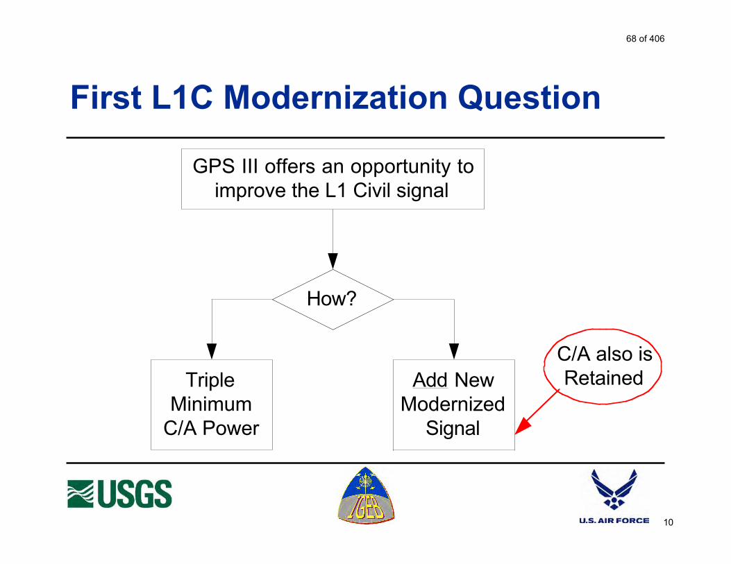
10
First L1C Modernization Question
GPS III offers an opportunity toimprove the L1 Civil signal
How?
TripleMinimum
C/A Power
Add NewModernized
Signal
C/A also isRetained
68 of 406

11
Add New Modernized Signal atDouble the Minimum C/A Power
Modulation
BOC(5,1)BOC(1,1)
Bit Rate
25 bps100 bps or
higher50 bps
What NewMessages?
CodeStructure ?
CodeStructure ?
Presume Equal Power Split between Dataand Data-less (pilot carrier) components
as in all modern GNSS signals
Demodulation ThresholdCompared to C/A at 50 bps:
100 bps is +5 - 3 - 3 = -1 dB 50 bps is +5 - 3 = +2 dB 25 bps is +5 - 3 + 3 = +5 dB
Next L1C Modernization Questions
?
69 of 406

12
?
TripleMinimum
C/A Power
Add ModernSignal at
2X MinimumC/A Power
?
BOC(5,1)
BOC(1,1)
?
100 bps orfaster
50 bps
25 bps
What NewMessages?
Choose One After Each Diamond
What is best foryour applications?
(?)
70 of 406

13
Questionnaire Page 1
71 of 406
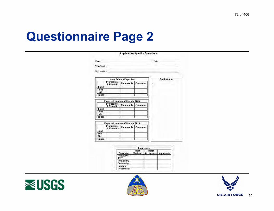
14
Questionnaire Page 2
72 of 406

15
Schedule a Web-Based Interview
E-mail: [email protected]: 626-583-7827Mail: L1C GPS
Attn: Ken Hudnut525 South Wilson Ave.Pasadena, CA 91106-3212
See Tom Stansell at the L1C [email protected]
73 of 406

A74 of 406

U.S. Department of the InteriorU.S. Geological Survey
1
L1 Modernization Project (L1C)
IEEE PLANS Meeting
Monterey, California; April 28, 2004
Ken Hudnut, Ph.D. Lt Bryan TitusProject Manager Navstar GPS JPO, Co-LeadGeophysicist, USGS Sat. Nav. Engineer, USAF
A75 of 406

2
Project Objectives
Obtain feedback from all GPS stakeholders on whether or not,and – if so – how best to add, a modernized signal on L1. Assess interference to legacy L1 C/A receivers, recognizing that
full backwards compatibility is essential.
Form recommendations to the IGEB on whether or not, andhow, the GPS L1 civil signal should be modernized.
The U.S. Government has not yet determined whether amodernized GPS L1 civil signal should be added.
76 of 406

3
Technical Considerations
Compatibility with US/Allied security
Backward compatibility with legacy C/A receivers
Signal design
Message options
Technical trade-offs for user benefits e.g., data rate
77 of 406

4
Stakeholder Interviews
Conducting surveys with domestic andinternational users Technical - interview to be conducted next here Non-technical - conducted user interviews
Consolidating the survey results First interim report recently submitted to IGEB Assessing which user groups remain - please
contact us at [email protected] to arrange fora full interview with your organization
78 of 406

5
L1C Project Interviews Conducted
CGSICNAVCEN Booth Activities at IONJPLUS GPS Industry CouncilNASANGS/NOAAU.S. Coast GuardThales NavigationJapan GPS Council MembersUniversity of New BrunswickLincoln LaboratoryITT Aerospace CommunicationsUniversity of New South Wales
NavWardUniversity of CalgaryStanford UniversityTrimble NavigationTalk and Poster at IGS MeetingTalk at CGSIC MeetingGarminNovAtelLeicaRFMDSiRFRockwell-CollinsIEEE - PLANS 2004 Meeting
79 of 406

6
Final Steps
Will conduct second technical meeting
Will prepare final IGEB report, including: Process descriptions Survey results Cost-benefit analysis Policy recommendations Signal design recommendations
80 of 406

U.S. Department of the InteriorU.S. Geological Survey
1
Improving the GPS L1 Signal
GPS III Offers the Opportunity
81 of 406

2
Introducing
2Lt. Jason TaylorTom
Stansell
1Lt. Bryan Titus
Co-Chair, JPO
Dr. Ken HudnutCo-Chair, USGS
82 of 406

3
Estimated Signal Availability
2005 2006 2007 2008 2009 2010 2011 2012 2013
28
24
20
16
12
8
4
0
L2C
L5
~ 2.7 Yrs.
Est
imat
ed N
o. o
f L2C
, L5,
& L
1C G
PS
Sig
nals
2014 2015 2016
L1C
~ 7.7 Yrs.
~ 5 Yrs.
Assumes eight IIR-M satellites and average of
three successful
launches per year
Not Official
83 of 406

4
First L1C Modernization Question
GPS III offers an opportunity toimprove the L1 Civil signal
How?
TripleMinimum
C/A Power
Add NewModernized
Signal
C/A also isRetained
84 of 406

5
Where To Fit a New L1 Signal ?
-95
-90
-85
-80
-75
-70
-65
-60
-55
-20 -15 -10 -5 0 5 10 15 20
Offset from 1575.42 MHz Center Frequency (MHz)
Po
wer
Sp
ectr
al D
ensi
ty (
dB
W/H
z)
L1 C/A Code
L1 P(Y) Code
L1 M Code
L1 Spectrum
L1 already will have C/A, P(Y),
and M code signals
Finding space for a new signal is a challenge
Compromise is required
85 of 406
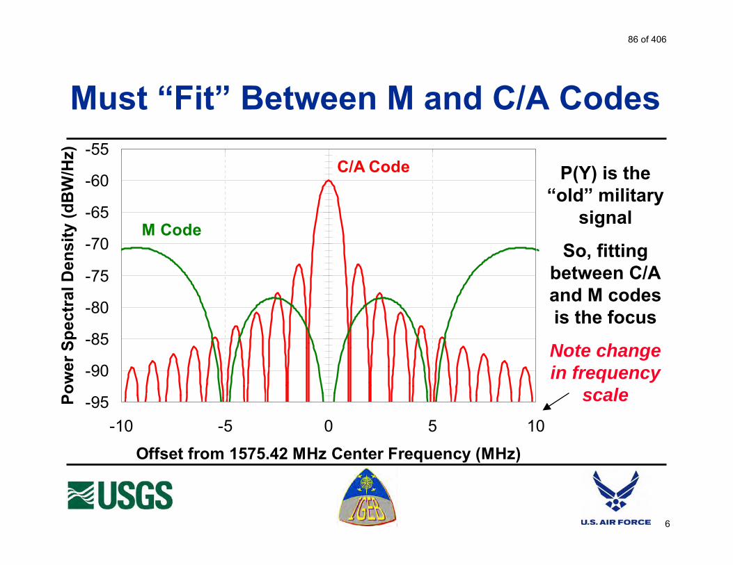
6
Must “Fit” Between M and C/A Codes
-95
-90
-85
-80
-75
-70
-65
-60
-55
-10 -5 0 5 10
Offset from 1575.42 MHz Center Frequency (MHz)
Po
wer
Sp
ectr
al D
ensi
ty (
dB
W/H
z)
C/A Code
M Code
P(Y) is the “old” military
signal
So, fitting between C/A and M codes is the focus
Note change in frequency
scale
86 of 406

7
Such As BOC(1,1) (OK for M and for C/A)
BOC(1,1) Spectral
Separation Coefficient
(SSC)
For C/A = -67.8 dB/Hz
For M =-82.4 dB/Hz
87 of 406

8
What’s a BOC ?
BOC = Binary Offset Carrier
The code is modulated by a square wave
M code is a BOC(10,5)5 MHz code modulated with a 10 MHz square wave
BOC(1,1)1 MHz code modulated with a 1 MHz square wave
Code Chips 1, 0 Square Wave Transmit Signal
88 of 406

9
Two U.S. Signal Spectrum Candidates
Government will decide
BOC(1,1)OK C/A and M Compatibility
Permits 4 MHz receiver bandwidthThe Leading Candidate
BOC(5,1) (?)Better C/A and M Compatibility
8 dB better code loop S/NConcern about correlation sub-peaks
Requires >= 12 MHz receiver bandwidth
BOC(1,1)
BOC(5,1)
89 of 406

10
Galileo Signal Decision http://europa.eu.int/rapid/start/cgi/guestfr.ksh?p_action.gettxt=gt&doc=IP/04/264|0|RAPID&lg=EN&display=
Loyola de Palacio welcomes the outcome of EU/US discussions on GALILEO
The United States and the European Commission, joined by the European Union Member States, held a successful round of negotiations in Brussels on 24-25 February 2004. The delegations built upon progress made in The Hague and in Washington and were able to reach agreement on most of the overall principles of GPS/Galileocooperation. ---------------------------------------------------------------------------------------------------------------------------------------------------------------
• Adoption of a common baseline signal structure for their respective open services (the future GPS intends to use a BOC 1,1 signal whereas the Galileo open service intends to use a fully compatible optimized version of the same signal which guarantees an high-level of performance).
90 of 406

11
Autocorrelation Functions (Absolute Value)
BOC(5,1)
BOC(1,1) Government will decide
BOC(1,1)OK C/A and M Compatibility
Permits 4 MHz receiver bandwidthThe Leading Candidate
BOC(5,1) (?)Better C/A and M Compatibility
8 dB better code loop S/NConcern about correlation sub-peaks
Requires >= 12 MHz receiver bandwidth
91 of 406

12
Multipath Defined
92 of 406

13
0 1000500Multipath Delay (nsec)
BOC(1,1)
BOC(5,1)
MultipathMitigation
Narrow Correlator Multipath Error
Not intended to be precise
Short delays generally cause the most trouble
93 of 406

14
Multipath Performance
With multipath mitigation, there is no effective difference in multipath error
Requires wide bandwidth receiver processing
Without multipath mitigation, higher code clock rates do reduce multipath error
However, short delay multipath generally causes more trouble and affects all signal options
Local reflections tend to be stronger
Phase change tends to be much slower, so filtering is less effective (carrier-aided code smoothing)
94 of 406

15
GPS III Power Control Thinking
Total C/A + L1C (-151.2 dBW Max)
L1C (-153 dBW Max)
Future C/A(-158.5 dBW Min at
5 degrees El.)
Current C/A Measurements
95 of 406

16
First L1C Modernization Question
GPS III offers an opportunity toimprove the L1 Civil signal
How?
TripleMinimum
C/A Power
Add NewModernized
Signal
C/A also isRetained
96 of 406

17
Triple Minimum C/A Power (4.77 dB)
Advantages
Simple improvement
Increase minimum C/A power by 4.77 dB
No receiver change to benefit
Helps all C/A users, one launch at a time
(Also could hurt)
Disadvantages
Raises C/A noise floor 1.8 dB
Net is 4.8 – 1.8 = 3.0 dB (x3 yields x2 effectiveness)
Data also only 3 dB better
Retains fixed data format
Unimproved crosscorrelation(Increased strong-to-weak signal correlation may force receiver software updates if not a receiver replacement)
Not a “competitive” signal
97 of 406

18
New L1C Signal Improvements
Twice the minimum C/A signal powerLonger codes (10,230 chips minimum)
Eliminate cross-satellite correlation interferenceReduce effect of narrowband interference
Message improvementsHigher resolution, reduced error rate, more flexible
Data-less signal componentPilot carrier improves tracking thresholdBetter for high precision phase measurements
Increase signal bandwidth (code clock rate)Added interference protection, less code noise
98 of 406

19
Add New Modernized Signal atDouble the Minimum C/A Power
Modulation
BOC(5,1)BOC(1,1)
Bit Rate
25 bps100 bps or
higher50 bps
What NewMessages?
CodeStructure ?
CodeStructure ?
Presume Equal Power Split between Dataand Data-less (pilot carrier) components
as in all modern GNSS signals
Demodulation ThresholdCompared to C/A at 50 bps:
100 bps is +5 - 3 - 3 = -1 dB 50 bps is +5 - 3 = +2 dB 25 bps is +5 - 3 + 3 = +5 dB
Next L1C Modernization Questions
?
99 of 406

20
L1C Modulation Choices
Choice will be made by the Government and must balance between interference to legacy C/A users and national security
BOC(1,1) seems to be the best compromise
BOC(5,1) is better for interference but risks tracking the wrong autocorrelation peak and forces a wide receiver bandwidth
Longer codes solve the C/A crosscorrelation problem (strong signal interference with weak signals)
100 of 406
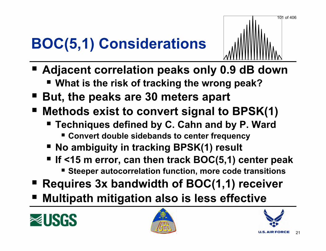
21
BOC(5,1) Considerations
Adjacent correlation peaks only 0.9 dB downWhat is the risk of tracking the wrong peak?
But, the peaks are 30 meters apartMethods exist to convert signal to BPSK(1)
Techniques defined by C. Cahn and by P. WardConvert double sidebands to center frequency
No ambiguity in tracking BPSK(1) resultIf <15 m error, can then track BOC(5,1) center peak
Steeper autocorrelation function, more code transitions
Requires 3x bandwidth of BOC(1,1) receiverMultipath mitigation also is less effective
101 of 406

22
Data Structure Improvements
A modern signal would share message structure improvements with L2C and L5
Forward Error Correction (FEC) improves data threshold by 5 dB
High resolution ephemeris (1 cm)
Compact almanac (7 satellites in one message block)
Staggered almanac timing speeds collection
Message will define the satellite
102 of 406

23
100 bps Data Rate or Faster
Advantages
Permits additional messagesIntegrity data?
Differential corrections?
What new messages would you want?
Disadvantages
Requires more signal power to receive any message
100 bps requires 4 times more signal power than 25 bps (6 dB)
Signal must be 6 dB above tracking threshold to obtain messages
Autonomous, not assisted, tracking threshold
103 of 406

24
25 bps Data Rate
Advantages
Messages can be acquired at the autonomous signal tracking threshold(not Assisted GPS threshold)
Especially helps in poor signal conditions such as in a forest, on a tree-lined road, indoors, or with interference
In a tough environment can be the difference between working and not working
Disadvantages
Requires twice as long to obtain messages compared with 50 bps
Clock & Ephemeris in: • 18 to 24 sec at 50 bps• 36 to 48 sec at 25 bps
Time To First Fix (TTFF) can be 24 seconds longer than with 50 bps (traditional rate)
104 of 406

25
?
TripleMinimum
C/A Power
Add ModernSignal at
2X MinimumC/A Power
?
BOC(5,1)
BOC(1,1)
?
100 bps orfaster
50 bps
25 bps
What NewMessages?
Choose One After Each Diamond
What is best for your applications?
(?)
105 of 406

26
Questionnaire Page 1
106 of 406

27
Questionnaire Page 2
107 of 406

L1C Technical Presentation These pages present the slides used in the technical presentation. Some of the presentations were made in a conference room setting, but most were presented over the WEB to one or more locations at a time. After the presentation, participants were asked to fill in and submit a questionnaire to express their L1C preferences. Below is the title slide.
The title slide is used to explain that this is an Interagency GPS Executive Board (IGEB) Stewardship Project with two sponsors: the U.S. Geological Survey (USGS) and the U.S. Air Force GPS Joint Program Office. It also points out that the subject is whether and how to improve the GPS civil signal on the L1 frequency and that the GPS III program offers an opportunity to introduce signal changes.
U.S. Department of the InteriorU.S. Geological Survey
1
Improving the GPS L1 Signal
GPS III Offers the Opportunity
A108 of 406

Because not everyone could be involved in each discussion, Slide 2 introduces the key participants in these technical presentations. The co-chairs are Dr. Ken Hudnut of the USGS earthquake research office in Pasadena, CA. Bryan Titus, now Capt. Titus, has been the co-chair from the GPS Joint Program Office. It was anticipated that Capt. Titus would transfer out of the JPO before this project ended, and his anticipated replacement was to have been Lt. Jason Taylor, shown above. However, plans change, and Bryan’s replacement on this project is Capt. Dominic (Dom) Alcocer.
2
Introducing
2Lt. Jason TaylorTom
Stansell
1Lt. Bryan Titus
Co-Chair, JPO
Dr. Ken HudnutCo-Chair, USGS
109 of 406

Slide 3 was a late addition to the presentation to give a sense of the L1C schedule relative to other new GPS civil signals. The plot is NOT official and DOES NOT reflect a plan or a promise by the U.S. Government. The plot assumes that on average there will be three successful GPS satellite launches per year for the indefinite future. Some will say that GPS III satellites may be launched two or more at a time and pressure to improve civil and military performance will fund a faster launch rate. Others will argue that IIR, IIR-M, and IIF satellites may last longer than IIA satellites and budget constraints will continue the policy of launching only when a replacement satellite is needed. Therefore, it is reasonable to assume 3 per year. The chart shows the estimated number of new civil signals being transmitted in 2005 and beyond. The first IIR-M probably will be launched early in 2005 with L2C, the first modernized civil signal. Only 8 IIR-M satellites will be launched. After that the IIF series will commence, providing both L2C and L5. (Note that the first IIF may be launched before 2007. However, this will not accelerate the availability of L5, because all of the IIR-M satellites eventually will be launched, delaying availability of L5 relative to L2C by 8 launches. At 3 per year, this is approximately 2.7 years, as shown on the plot. Current plans call for the first GPS III to be launched by 2012. Presumably this would be the first time an improved L1 signal (L1C) could be available. The plot assumes that starting in late 2005 only GPS III satellites will be launched. This is extremely optimistic, so a delay of more than 7.7 years relative to L2C is likely, unless later versions of the IIF are modified to carry L1C. Note that L2C and L1C share the characteristic that they are adding capability to existing signals. Thus, the first signals are valuable, because they will be used in conjunction with the existing signals. In contrast, L5 does not exist today, so many launches are required to provide a service.
3
Estimated Signal Availability
2005 2006 2007 2008 2009 2010 2011 2012 2013
28
24
20
16
12
8
4
0
L2C
L5
~ 2.7 Yrs.
Est
ima
ted
No
. o
f L
2C
, L
5,
& L
1C
GP
S S
ign
als
2014 2015 2016
L1C
~ 7.7 Yrs.
~ 5 Yrs.
Assumes eight IIR-M satellites and average of
three succe ssful
launches per year
Not Official
110 of 406

Slide 4 asks the primary question of whether a new L1 signal is wanted or needed. On the left is the alternative of “simply” increasing the power of the existing C/A signal. Presumably that would improve performance for all current users and avoid the difficulties of providing a new signal. On the right is the other approach of adding a new, modernized civil signal at the L1 frequency. This idea has raised much concern that C/A would be discontinued and replaced with a new signal. To address this concern, it was a ground-rule of this study that the C/A signal would be retained indefinitely. A new signal would be an addition not a substitution. On the other hand, there are those who can envision a time, many decades from now, when the number of legacy users dependant on C/A will have all but disappeared. This will occur naturally as all new receiver designs become compatible with the modernized signals. A new generation of GPS experts will then have to decide whether to discontinue C/A and transfer it’s power to the modernized signal. This is of no concern for today’s users, because C/A will be retained indefinitely. However, it is important for signal designers to assure that a path exists so C/A could be discontinued in the distant future without then disrupting legacy L1C use.
4
First L1C Modernization Question
GPS III offers an opportunity toimprove the L1 Civil signal
How?
TripleMinimum
C/A Power
Add NewModernized
Signal
C/A also isRetained
111 of 406

Slide 5 shows the challenge of fitting a new signal in the GPS L1 Spectrum which seems full with the two existing C/A and P/Y signals plus the future M Code military signal. This and the next plot show power spectral density in dBW/Hz, which allows us to see very weak signal components throughout the GPS L1 band. The challenge is to insert a new signal which doesn’t add significant noise to existing C/A code receivers and which can be locally denied, along with the C/A code, by an allied military force while preserving use of the new M code military signal.
5
Where To Fit a New L1 Signal ?
-95
-90
-85
-80
-75
-70
-65
-60
-55
-20 -15 -10 -5 0 5 10 15 20
Offset from 1575.42 MHz Center Frequency (MHz)
Po
wer
Sp
ectr
al D
ensi
ty (
dB
W/H
z)L1 C/A Code
L1 P(Y) Code
L1 M Code
L1 Spectrum
L1 already will have C/A, P(Y),
and M code signals
Finding space for a new signal is a challenge
Compromise is required
112 of 406

Slide 6 emphasizes that the main requirement of a new signal is to fit between the new M code and the C/A code signals. M code was developed specifically to provide spectral separation between civil and military signals, so there must be significant separation between any new civil signal and the M code. In addition, a new civil signal must not interfere with legacy C/A code users.
6
Must “Fit” Between M and C/A Codes
-95
-90
-85
-80
-75
-70
-65
-60
-55
-10 -5 0 5 10
Offset from 1575.42 MHz Center Frequency (MHz)
Po
we
r S
pe
ctr
al D
en
sit
y (
dB
W/H
z)C/A Code
M Code
P(Y) is the “old” military
signal
So, fitting between C/A and M codes is the focus
Note change in frequency
scale
113 of 406

Slide 7 shows the spectrum of a BOC(1,1) signal, which is the leading candidate for a new civil signal. The main lobes of the signal are close enough to the spectrum center that there is “OK” separation from M code, and with a null at the center there is sufficient separation from the C/A code. The measure of separation is the Spectral Separation Coefficient (SSC) which is obtained from convolving the spectra of the two signals. The SSC quantifies the effect of the interference from one signal to a linear receiver of the other signal. For example, the SSC between a BOC(1,1) signal and the C/A code is –67.8 dB/Hz. To determine the interference caused by the aggregate power of all incident BOC(1,1) signals to a C/A code receiver, the aggregate power at a worst case time and position (the “hot spot”) is transformed by the SSC into the noise power density affecting a C/A code receiver. From other evaluations, the hot spot power is about 11.5 dB higher than the peak power transmitted by each satellite, depending on the user equipment antenna pattern. The peak L1C power from each satellite is taken from Slide 15 to be –153 dBW. Therefore, the hot spot power is about –141.5 dBW. Based on the BOC(1,1) SSC value, the resultant interference to a C/A receiver is –209.3 dBW/Hz, which is well under the –201 dBW/Hz noise floor of a C/A receiver with a 3 dB noise figure. Even so, at the hot spot this would cause a 0.6 dB increase in the C/A receiver noise floor, which is one reason the GPS Joint Program Office recently revised the minimum C/A power specification from –160 to –158.5 dBW. This 1.5 dB increase in specified minimum power more than compensates for all the new signals expected in the L1 frequency band. This discussion included assumptions which may be different in other evaluation scenarios. For example, the maximum power transmitted by the satellites and the user equipment antenna pattern are assumptions. Whether or not Galileo or other L1 signals are included makes a difference. In fact, the results also depend on whether C/A to C/A mutual interference is included or not. The purpose here is to show the concept, not to draw definitive conclusions.
7
Such As BOC(1,1) (OK for M and for C/A)
BOC(1,1) Spectral
Separation Coefficient
(SSC)
For C/A = -67.8 dB/Hz
For M =-82.4 dB/Hz
114 of 406

Slide 8 describes the BOC waveform. For BOC(1,1), the diagram at the bottom shows two code chips, the modulating square wave, and the resulting transmitted signal.
8
What’s a BOC ?
BOC = Binary Offset Carrier
The code is modulated by a square wave
M code is a BOC(10,5)5 MHz code modulated with a 10 MHz square wave
BOC(1,1)1 MHz code modulated with a 1 MHz square wave
Code Chips 1, 0 Square Wave Transmit Signal
115 of 406

Slide 9 shows the spectrum of the two waveform candidates being offered for consideration: BOC(1,1) and BOC(5,1). The red question mark was added after the U.S. and the European Union (EU) announced tentative agreement on BOC(1,1) as the prototype civil signal that both GPS and Galileo would transmit in the L1 band. Although it would seem that BOC(1,1) has been anointed, the actual agreement was that the waveform must meet a specific set of compatibility criteria relative to the C/A and M codes. In this regard, BOC(5,1) is better than BOC(1,1) on both counts. It is likely the US and the EU will use identically the same waveform on L1, but it can be any waveform which meets the criteria. Some have proposed that BOC(5,1) would give better performance than BOC(1,1). If BOC(5,1) receives significant industry support, it remains possible for the US and EU negotiators to select BOC(5,1). The main performance advantage of BOC(5,1) is that it has 9.5 “transitions” per microsecond versus 1.5 for BOC(1,1). As a result, with adequate receiver bandwidth the code tracking loop S/N is 8 dB better than with BOC(1,1). Opponents would argue that this is of little significance because with carrier aided code smoothing the C/A code, which has only 0.5 transitions per microsecond, achieves code tracking performance of a few centimeters and that ionospheric and multipath errors, not the loop S/N, are the dominant sources of code noise. A key difference in the waveforms is that BOC(1,1) can be processed with a receiver bandwidth as little as 4 MHz whereas BOC(5,1) requires a minimum bandwidth of 12 MHz. Proponents of BOC(1,1) say that very low cost, low power, embedded receivers benefit from a narrow bandwidth signal rather than having to increase clock rates and employ a more complex filter for a wider bandwidth signal. Proponents of BOC(5,1) counter that the advance of technology should solve both these problems.
9
Two U.S. Signal Spectrum Candidates
Government will decide
BOC(1,1)OK C/A and M Compatibility
Permits 4 MHz receiver bandwidthThe Leading Candidate
BOC(5,1) (?)Better C/A and M Compatibility
8 dB better code loop S/NConcern about correlation sub-peaks
Requires >= 12 MHz receiver bandwidth
BOC(1,1)
BOC(5,1)
116 of 406

Slide 10 highlights a key part of the agreement reached between the US and the EU. As quoted from a press release by Loyola de Palacio, the US and the EU adopted a “common baseline signal structure” on L1 for both GPS and Galileo. The phrase “optimized version of the same signal” shows that EU experts are evaluating other waveforms which meet the agreed compatibility criteria. These could include BOC(5,1) or minor variations of BOC(1,1). Because proposed launch schedules require the EU to commit to a waveform before the US, it is very unlikely the US would select a waveform which does not perform as well as the Galileo signal. In fact, it is likely the waveforms provided by GPS and by Galileo will be identical. The main point is that the US and the EU have agreed on compatibility criteria for selecting a waveform and BOC(1,1) is the initial choice but other variants are being considered.
10
Galileo Signal Decision http://europa.eu.int/rap id/start/cgi/guestfr.ksh?p_action.gettxt=gt&doc=IP/04/264|0|R APID&lg=EN&display=
Loyola de Palacio welcomes the outcome of EU/US discussions on GALILEO
The United States and the European Commission, joined by the European Union Member States, held a successful round of negotiations in Brussels on 24-25 February 2004. The delegations built upon progress made in The Hague and in Washington and were able to reach agreement on most of the overall principles of GPS/Galileocooperation.
---------------------------------------------------------------------------------------------------------------------------------------------------------------
• Adoption of a common baseline signal structure for their respective open services (the future GPS intends to use a BOC 1,1 signal whereas the Galileo open service intends to use a fully compatible optimized version of the same signal which guarantees an high-level of performance).
117 of 406

Slide 11 compares the absolute value of the BOC(1,1) and the BOC(5,1) autocorrelation functions. As you recall, the C/A code, BPSK(1) autocorrelation function has the same width but only one peak at the center. BOC(1,1) has three peaks, but the sub-peaks are at half (voltage) amplitude relative to the correct center peak. This 6 dB power difference is considered easy to detect, so if receivers are designed to avoid a false lock, the probability of tracking the wrong peak is considered negligible. The slope of the center of the BOC(1,1) autocorrelation function is 3 times steeper than the slope of a BPSK(1) autocorrelation function because there are 1.5 signal transitions per microsecond for BOC(1,1) and 0.5 transitions for BPSK(1). The central peak slope of the BOC(5,1) autocorrelation function is 6.33 times that of the BOC(1,1) slope because the BOC(5,1) waveform has 9.5 transitions per microsecond. This characteristic improves code loop S/N, but as shown in the figure it introduces concern a receiver could falsely lock to and track a sub-peak. The concern is heightened because the sub-peaks on either side of the central peak are only 0.9 dB below the central peak.
11
Autocorrelation Functions (Absolute Value)
BOC(5,1)
BOC(1,1) Government will decide
BOC(1,1)OK C/A and M Compatibility
Permits 4 MHz receiver bandwidthThe Leading Candidate
BOC(5,1) (?)Better C/A and M Compatibility
8 dB better code loop S/NConcern about correlation sub-peaks
Requires >= 12 MHz receiver bandwidth
118 of 406

Slide 12 is in case a respondent doesn’t understand the physical nature of multipath. The desired signal is the direct signal from the satellite to the receiver antenna. However, the antenna also receives the same signal when reflected from any surface in view. The only valuable signal is the direct signal. All reflected signals introduce distortions and noise which hurt accuracy and can cause significant signal fading. Several methods are used to reduce the amplitude and minimize the effect of these multipath signals. The satellite signals are transmitted with left hand circular polarization, and good user antennas match that polarization because the polarization of one-bounce multipath signals are reversed to right hand circular. Thus, good circular polarization of user antennas helps attenuate multipath signals. Antennas which can be hard mounted often are designed to minimize the reception of signals near or below the horizon because most multipath signals arrive at a low or negative elevation angle. Within the receiver there are two main ways to minimize the impact of multipath. The first is carrier aided code tracking. Because the L1 carrier wavelength is 19 centimeters, the multipath effect is measured in centimeters. On the other hand, the multipath effect on code tracking is measured in meters. The carrier signal very precisely measures the change in range between the satellite and the user, but unlike the code signal it doesn’t provide an absolute measure of the total pseudorange. Carrier aided code smoothing combines the precision of carrier measurements with unambiguous code measurements to provide information with far less multipath noise. The second receiver technique is to employ a multipath mitigation code correlator. The earliest version of this is the “narrow correlator” which significantly reduces the impact of multipath signals. More effective techniques also have been developed and are in use.
12
Multipath Defined
119 of 406

Slide 13 addresses the issue of whether the choice of signal waveform will affect receiver multipath performance. The graphic is not intended to be precise but to illustrate the issues. The plot shows the error caused by a single multipath signal, when tracking with a narrow correlator, as a function of its arrival time relative to the direct signal. Delays beyond just over 1000 nanoseconds (ns) have no effect because the reflected signal is completely de-correlated by the pseudorandom code which has a chip period of 1000 ns. As the carrier phase of the multipath signal changes relative to the carrier phase of the direct signal the code error slowly oscillates between the limits defined by the figure. A BPSK(1) signal like the C/A code has an error profile which rises from zero to the two maxima and remains there until just beyond 1000 ns. The BOC(1,1) profile (shown in blue) is the same except that at the half way point the polarity of the error limits is reversed and the amplitude becomes one third that during the first half. This, of course, is due to the 1 MHz square wave modulating the 1 MHz code. The BOC(5,1) signal (shown in red) has nine reversals of polarity and the error amplitude is reduced after each one. On the surface it would seem that either of these would be better than the BPSK(1) C/A code, but the reality is more complicated. In particular, most multipath signals, especially those which do the most harm, have a short delay. Studies have shown that in most circumstances there is little or no multipath energy beyond a delay of 300 ns, and the amplitude falls off rapidly over this range. In addition, use of a multipath mitigation correlator, as illustrated in green, means to first order that there is no difference in performance with either of the signal waveforms. Performance is determined by the receiver design. Although this is true with one of the several types of multipath mitigation correlator, the most often used such correlator, such as the double delta or Strobe correlator, suffers another “secondary” multipath response at each polarity change. From this perspective, it would be better to use the double delta or Strobe type correlator with the BOC(1,1) waveform than with the BOC(5,1) correlator.
13
0 1000500Multipath Delay (nsec)
BOC(1,1)
BOC(5,1)
MultipathMitigation
Narrow Correlator Multipath Error
Not intended to be precise
Short delays generally cause the most trouble
120 of 406

Slide 14 summarizes the points made with the previous slide. If multipath mitigation is used, there is no effective difference regardless of which waveform is chosen, except that with a double delta or Strobe type of correlator the secondary multipath responses with a BOC(5,1) waveform are closer to the origin where most of the multipath energy is found. All multipath mitigation correlators require a wide bandwidth receiver to function effectively.
14
Multipath Performance
With multipath mitigation, there is no effective difference in multipath error
Requires wide bandwidth receiver processing
Without multipath mitigation, higher code clock rates do reduce multipath error
However, short delay multipath generally causes more trouble and affects all signal options
Local reflections tend to be stronger
Phase change tends to be much slower, so filtering is less effective (carrier-aided code smoothing)
121 of 406

Slide 15 shows the proposed L1C and C/A power sharing ideas. It is based on the premise that GPS III will be able to precisely control the power of each of its signal components. Note first that the specified minimum C/A signal power received by a +3 dBi linearly polarized antenna, oriented to receive the minimum signal power, is –158.5 dBW at 5 degrees of elevation and above. Although the critical elevation angle is 5 degrees, the specified minimum power is the same at all elevation angles above 5 degrees. The fact that signal power does increase at higher elevation angles is an artifact of satellite antenna design limitations. The ideal satellite antenna would deliver constant power at every elevation angle. The small circles represent actual C/A signal power measurements from many GPS satellites as a function of elevation angle. Clearly there is more C/A signal power than the specified minimum. Although not official, and still under evaluation, the GPS JPO suggested that it would be acceptable for the maximum total civil signal power on L1 to be –151 dBW. This may have to be reduced somewhat not only for national security reasons but also to limit inter-signal interference, especially when the total GPS plus Galileo signal power is considered. However, working with these numbers it would be possible to increase the current C/A signal to the total power curve at the top of the figure. On the other hand, to provide the best new L1C performance, C/A power would be reduced to the lower curve, leaving room for L1C to be more powerful than any of the current C/A signals. The reduced C/A power would more than meet the current signal specification, and there would be seven or more years before the first GPS III launch, in 2012 or beyond, for a large fraction of current receivers to be replaced by L1C-enabled versions. Legacy C/A-only receivers still in use would receive signals closer to the specification level than now from the new satellites. In this way, legacy signals are preserved while encouraging users to upgrade to receivers compatible not only with L1C but also the expected new Galileo signals. For a smooth transition it is important for US and EU authorities to publish complete signal specifications as soon as possible.
122 of 406

Slide 16 is not reproduced here. Having covered the background material, Slide 16 was a repeat of Slide 4 to return to the basic question of whether simply to increase the C/A signal power or to add a new signal, such as a BOC(1,1) L1C signal, while also retaining the C/A code. Slide 17 examines the advantages and disadvantages of simply increasing the C/A signal power. The suggested increase of 4.8 dB would be with respect to the specified minimum signal power of –158.5 dBW. Presumably this option would be relatively simple, and every legacy C/A user could benefit. Unfortunately, there are disadvantages as well. The SSC of one C/A signal with respect to another is 6 dB worse than the effect of BOC(1,1) signals on C/A. With the suggested power increase, as shown in Slide 15, the maximum power of each C/A signal would be –151.2 dBW, so the hot spot discussed with Slide 7 would be at –139.7 dBW. The resultant interference to a C/A receiver is –201.3 dBW/Hz, which is barely under the –201 dBW/Hz noise floor of a C/A receiver with a 3 dB noise figure. At the hot spot this would cause a 2.8 dB increase in the C/A receiver noise floor, based on the same assumptions used with Slide 7 for a BOC(1,1) signal. Most important, both analyses ignore all other interference sources. Regardless of the assumptions, however, it is clear that simply increasing C/A power is not an effective way to improve the L1 civil signal.
17
Triple Minimum C/A Power (4.77 dB)
Advantages
Simple improvement
Increase minimum C/A power by 4.77 dB
No receiver change to benefit
Helps all C/A users, one launch at a time
(Also could hurt)
Disadvantages
Raises C/A noise floor 1.8 dB
Net is 4.8 – 1.8 = 3.0 dB (x3 yields x2 effectiveness)
Data also only 3 dB better
Retains fixed data format
Unimproved crosscorrelation(Increased strong-to-weak signal correlation may force receiver software updates if not a receiver replacement)
Not a “competitive” signal
123 of 406

Slide 18 lists a number of L1C improvements relative to C/A in addition to more signal power (“twice the minimum C/A signal power”). Every modernized GPS signal (L2C, L5, and M code) employs a much longer code than the 1023 chip C/A code. The minimum code length for L2C and for L5 is 10,230 chips, and undoubtedly this would be the same for L1C. This will greatly reduce and practically eliminate cross-satellite interference which is a significant problem with C/A code. (A powerful GPS signal can be acquired by a C/A receiver looking for a different satellite because the code provides as little as 21 to 23 dB of crosscorrelation protection.) A longer code also reduces the impact of narrowband interference. L1C naturally would provide the modernized message structure which will be implemented on L2C and L5. This includes higher resolution (a few centimeters rather than ~40 cm), use of forward error correction (FEC), a strong cyclic redundancy check (CRC) to validate individual messages, and a more flexible message structure. Very importantly, L1C also will provide two signal components, one with data and one without data, i.e., a pilot carrier, which improves tracking threshold by a minimum of 3 dB. Finally, L1C will have a broader spectrum (more waveform transitions) than C/A code, which adds some interference protection and improves code loop S/N. The strong CRC alone can be an important improvement. For example, certified aviation receivers today are required to receive two identical copies of the ephemeris message before it can be used for navigation. This is because the check sum error detection employed today is not strong enough to guarantee no errors after receiving just one message. The modern CRC is sufficient to guarantee no errors with just one message. This by itself can accelerate time to first fix (TTFF) or time to first use of a newly acquired signal.
18
New L1C Signal Improvements
Twice the minimum C/A signal powerLonger codes (10,230 chips minimum)
Eliminate cross-satellite correlation interferenceReduce effect of narrowband interference
Message improvementsHigher resolution, reduced error rate, more flexible
Data-less signal componentPilot carrier improves tracking thresholdBetter for high precision phase measurements
Increase signal bandwidth (code clock rate)Added interference protection, less code noise
124 of 406

Slide 19 asks the next key questions. If you prefer having a modernized signal, which modulation waveform do you recommend, BOC(1,1) or BOC(5,1)? Also, what message bit rate do you prefer? The advantages and disadvantages of the two modulation waveforms have been covered adequately in previous slides. To help make the bit rate decision, a small table is included on the slide. If we compare the L1C signal to a C/A signal of equal power, the L1C signal will have a 2 dB better data demodulation threshold than the C/A signal. This is mostly because forward error correction (FEC) will be used. The FEC algorithm adopted for L2C and L5 yields a 5 dB improvement in threshold. (An improved algorithm may be considered for GPS III.) This is reduced by 3 dB because the power of modern signals is divided equally between data and data-less components. The net at 50 bps is an improvement of 2 dB. If a 100 bps data rate is chosen there is another reduction of 3 dB because only half the energy is available per bit. The result is a 1 dB performance penalty relative to a 50 bps C/A signal. Conversely, choosing a 25 bps rather than 50 bps gains 3 dB, giving a 5 dB advantage over C/A code. The advantage of higher data rates is having more data in the same time or the same amount of data quicker. The advantage of 25 bps is that the message recovery threshold is approximately the same as the signal acquisition and tracking threshold. If a user can barely acquire and track the signal in a challenged environment, 25 bps also allows the message to be acquired so navigation can begin. At higher data rates a stronger signal is required to demodulate the message. Responses occur in three general groups. One wants a faster data rate so additional integrity or differential correction messages can be provided. The second group wants a faster rate so necessary messages can be acquired sooner to improve TTFF or to use a fresh satellite quicker. The third group is concerned about using GPS in challenged environments, such as in a forest, inside a building, or when subject to interference, so they want a slower rate to assure navigation.
19
Add New Modernized Signal atDouble the Minimum C/A Power
Modulation
BOC(5,1)BOC(1,1)
Bit Rate
25 bps100 bps or
higher50 bps
What NewMessages?
CodeStructure ?
CodeStructure ?
Presume Equal Power Split between Dataand Data-less (pilot carrier) components
as in all modern GNSS signals
Demodulation ThresholdCompared to C/A at 50 bps:
100 bps is +5 - 3 - 3 = -1 dB 50 bps is +5 - 3 = +2 dB 25 bps is +5 - 3 + 3 = +5 dB
Next L1C Modernization Questions
?
125 of 406

Slide 20 summarizes the L1C modulation choices. The choice will be made by the Government, and it will be greatly influenced by the US/EU negotiations regarding compatibility and interoperability of GPS and Galileo signals.
20
L1C Modulation Choices
Choice will be made by the Government and must balance between interference to legacy C/A users and national security
BOC(1,1) seems to be the best compromise
BOC(5,1) is better for interference but risks tracking the wrong autocorrelation peak and forces a wide receiver bandwidth
Longer codes solve the C/A crosscorrelation problem (strong signal interference with weak signals)
126 of 406
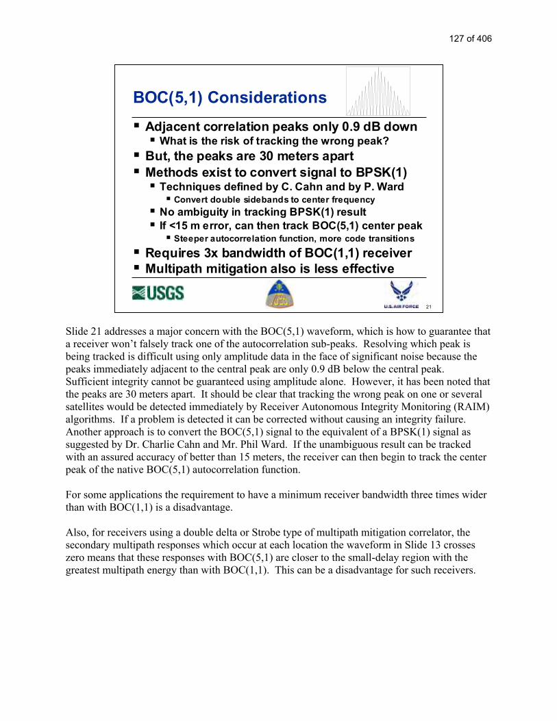
Slide 21 addresses a major concern with the BOC(5,1) waveform, which is how to guarantee that a receiver won’t falsely track one of the autocorrelation sub-peaks. Resolving which peak is being tracked is difficult using only amplitude data in the face of significant noise because the peaks immediately adjacent to the central peak are only 0.9 dB below the central peak. Sufficient integrity cannot be guaranteed using amplitude alone. However, it has been noted that the peaks are 30 meters apart. It should be clear that tracking the wrong peak on one or several satellites would be detected immediately by Receiver Autonomous Integrity Monitoring (RAIM) algorithms. If a problem is detected it can be corrected without causing an integrity failure. Another approach is to convert the BOC(5,1) signal to the equivalent of a BPSK(1) signal as suggested by Dr. Charlie Cahn and Mr. Phil Ward. If the unambiguous result can be tracked with an assured accuracy of better than 15 meters, the receiver can then begin to track the center peak of the native BOC(5,1) autocorrelation function. For some applications the requirement to have a minimum receiver bandwidth three times wider than with BOC(1,1) is a disadvantage. Also, for receivers using a double delta or Strobe type of multipath mitigation correlator, the secondary multipath responses which occur at each location the waveform in Slide 13 crosses zero means that these responses with BOC(5,1) are closer to the small-delay region with the greatest multipath energy than with BOC(1,1). This can be a disadvantage for such receivers.
21
BOC(5,1) Considerations
Adjacent correlation peaks only 0.9 dB downWhat is the risk of tracking the wrong peak?
But, the peaks are 30 meters apartMethods exist to convert signal to BPSK(1)
Techniques defined by C. Cahn and by P. WardConvert double sidebands to center frequency
No ambiguity in tracking BPSK(1) resultIf <15 m error, can then track BOC(5,1) center peak
Steeper autocorrelation function, more code transitions
Requires 3x bandwidth of BOC(1,1) receiverMultipath mitigation also is less effective
127 of 406

Slide 22 summarizes data structure improvements with a modernized signal. Presumably would use the same message structure already designed for L2C and for L5. These include FEC yielding at least 5 dB. Given the steady advance of chip technology (Moore’s Law), it may be appropriate to employ an FEC for L1C which exceeds the performance of the currently selected FEC. This would require the receiver chip to have somewhat more data storage and processing power, but Moore’s Law should make this possible at little or no meaningful cost. The new message provides a slant range (pseudorange) orbit and clock resolution (not necessarily accuracy) on the order of one centimeter. The resolution of today’s message is about 40 centimeters. Because orbit and clock accuracy is rapidly approaching 10 centimeters, better resolution is needed to prevent the message structure from limiting ultimate GPS accuracy. The potential for a “compact almanac” is being studied. The idea is to pack as many satellites into an almanac message as possible by assuming each orbit is perfectly circular. This approximation allows one message to provide up to seven satellite orbits. The penalty is that unknown orbit ellipticity can cause 300 to 500 Hz of signal frequency uncertainty which could increase acquisition time. Because almanac data also can be obtained in other ways, the decision may be to transmit a more accurate orbit description at a lower rate. Almanac acquisition also can be accelerated by having satellites transmit different almanac messages at the same time, taking maximum advantage of multi-channel receivers. The final point is more significant than it would seem. Certified aviation receivers now must compare every received ephemeris to a recent almanac to verify that the orbit is correct for the assumed satellite being tracked. This is because the poor crosscorrelation performance of the C/A code allows one strong signal to be mistaken for another satellite. Longer codes will eliminate this problem, but to make absolutely sure the message will identify the source satellite.
22
Data Structure Improvements
A modern signal would share message structure improvements with L2C and L5
Forward Error Correction (FEC) improves data threshold by 5 dB High resolution ephemeris (1 cm)
Compact almanac (7 satellites in one message block)
Staggered almanac timing speeds collection
Message will define the satellite
128 of 406

Slide 23 presents advantages and disadvantages of a higher data rate such as 100 bps or faster. The slide assumed there was only one reason for a faster rate, which would be to transmit additional information. Therefore it asks the respondent to identify what new messages would be desired, such as integrity or differential correction data. Late in the interview process it became clear that another group of users wanted a faster data rate in order to reduce time to first fix or time to use a fresh satellite signal. These users would not want additional messages which, from their perspective, would defeat the purpose for a faster data rate. The disadvantage is that a stronger signal is required to demodulate the message than is required to acquire and track the signal. One example of this disadvantage is that aircraft flying toward an area for which the FAA has issued a NOTAM to alert aviators that GPS will be unreliable in that region will be affected first by message loss before the receiver actually stops making reliable pseudorange measurements. At 25 bps, message demodulation and pseudorange measurements would be lost at about the same location. At 100 bps, message loss would occur about twice as far from the center of this region than loss of pseudorange tracking.
23
100 bps Data Rate or Faster
Advantage s
Permits additional messagesIntegrity data?
Differential corrections?
What new messages would you want?
Disadvantages
Requires more signal power to receive any message
100 bps requires 4 times more signal power than 25 bps (6 dB)
Signal must be 6 dB above tracking threshold to obtain messages
Autonomous, not assisted, tracking threshold
129 of 406

Slide 24 compares the advantages and disadvantages of a 25 bps data rate. The key advantage is that the message demodulation threshold is almost exactly the same as the signal tracking threshold. (Note that this statement assumes unassisted GPS operation with the potential for modest dynamics. Assisted GPS, e.g., for E-911 applications, has been shown to permit use with signals so weak the message could not possibly be demodulated.) For example, receivers operating under forest cover or aviation receivers operating near an area for which the FAA has issued a NOTAM alerting aviators that GPS in that region will be unreliable, can still obtain the satellite message with signals as weak as the receiver tracking threshold. In difficult environments this can mean the difference between having GPS navigation or not. The key disadvantage of 25 bps is that the data comes slower. The new message structure provides clock and ephemeris data in 18 to 24 seconds at 50 bps. That would be 9 to 12 seconds at 100 bps if additional messages are not added. At 25 bps the clock and ephemeris data requires 36 to 48 seconds. Therefore, time to first fix at 25 bps would be 24 seconds longer than at 50 bps and could be as much as 36 seconds longer than at 100 bps.
24
25 bps Data Rate
Advantages
Messages can be acquired at the autonomous signal tracking threshold(not Assisted GPS threshold)
Especially helps in poor signal conditions such as in a forest, on a tree-lined road, indoors, or with interference
In a tough environment can be the difference between working and not working
Disadvantages
Requires twice as long to obtain messages compared with 50 bps
Clock & Ephemeris in: • 18 to 24 sec at 50 bps• 36 to 48 sec at 25 bps
Time To First Fix (TTFF) can be 24 seconds longer than with 50 bps (traditional rate)
130 of 406

Slide 25 summarizes the questions being asked of the GPS experts. Starting at the left, the first question is whether simply to increase the C/A code power or to reduce the C/A power somewhat in order to add a modern L1C signal. If the respondent prefers the new signal, the next pair of questions address which waveform and which data rate is preferred. Two waveforms are offered, BOC(5,1) and BOC(1,1). The red question mark next to BOC(5,1) was added to signify that the US and the EU have agreed to have the same basic type of signal on L1, with the initial template being BOC(1,1). However, if respondents strongly support BOC(5,1) it would be possible for the US and the EU to change the template. The most difficult issue is data rate. As stated before, many want a higher data rate in order to transmit more information such as integrity messages and/or differential correction data. Others want a higher rate without additional messages in order to shorten time to first fix (TTFF). A third group is concerned about operation in challenged environments. They want a lower data rate in order to receive GPS messages any place the signal can be acquired and tracked. (Note that this does not apply to low dynamic, assisted GPS applications, such as E-911, where measurements can be made with even weaker signals.)
25
?
TripleMinimum
C/A Power
Add ModernSignal at
2X MinimumC/A Power
?
BOC(5,1)
BOC(1,1)
?
100 bps orfaster
50 bps
25 bps
What NewMessages?
Choose One After Each Diamond
What is best for your applications?
(?)
131 of 406

Slide 26 shows the top of the questionnaire form. Each respondent is asked to circle his or her choice, to list any additional messages they want GPS to transmit, and to provide comments as extensive as possible. Not shown, at the bottom of the page each respondent has the opportunity to designate whether his or her name and/or organization is for attribution or not. All responses are included in the final report. The name and/or organization, as well as other identifying information, for those requested non-attribution are deleted. However, the technical response and comments are retained.
26
Questionnaire Page 1
132 of 406

Slide 27 is the last in the presentation. It asks respondents to indicate their area(s) of greatest expertise, to list the applications of most interest to them, and to predict for these areas what number of GPS receivers will be in use in the years 2005 and 2020. It also asks respondents to rank order the importance of GPS characteristics such as accuracy, TTFF, availability, etc., and to indicate the range of performance from the best that could be used to the worst that would be acceptable.
27
Questionnaire Page 2
133 of 406

1
L1C Questionnaire Name: Date: Title/Position Organization Address Phone: E-Mail: Circle Preferences:
What new messages: Comments: Signature: For Attribution?: Your Name: Yes No Your Organization: Yes No
A134 of 406

2
Application Specific Questions Name: Date: Title/Position Organization
Your Primary Expertise
Professional & Scientific
Commercial Consumer
Land Sea Air
Space
Expected Number of Users in 2005
Professional & Scientific
Commercial Consumer
Land Sea Air
Space
Expected Number of Users in 2020
Professional & Scientific
Commercial Consumer
Land Sea Air Space
Applications 1.
Value
Parameter Best
Desired Worst
Acceptable
Importance Accuracy TTFF Availability Continuity Integrity Robustness
Importance: 1 = Very, 3 = Moderate, 5 = Not Significant
135 of 406

L1C Questionnaire Responses
The Following is Reference # 1
A136 of 406

137 of 406

138 of 406

139 of 406

140 of 406

141 of 406

142 of 406

Intentionally Left Blankto Separate Responses
The Following is Reference # 2
143 of 406

144 of 406

145 of 406

Intentionally Left Blankto Separate Responses
The Following is Reference # 3
146 of 406

1
L1C Questionnaire
Name: Date: Tuesday, July 06, 2004
Title/Position
Organization Aircraft Owners and Pilots Association
Address 421 Aviation Way, Frederick, MD 21701
Phone: 301-695-2211 E-Mail:
Circle Preferences:
What new messages:
Intentionally left blank.
Comments:
It is our observation that the future improvements to space based positioning, navigation, and timing
(PNT) are in a state of flux. Both the United States and European Union are planning to offer high
performance systems in the future. General aviation pilots use PNT services for thousands of flights
daily. Space based PNT is often the pilots’ only electronic navigation system onboard the aircraft.
Pilots also use these systems for other onboard features such as terrain awareness, traffic avoidance,
147 of 406

2
weather in the cockpit, electronic charting of airspace boundaries and temporary flight restriction
airspace depiction. Pilots increasingly rely on PNT for all weather access to general aviation airports.
Because general aviation is increasingly using space based PNT for daily operations, we offer the
following comments:
The general aviation community should not be expected to upgrade their aircraft navigation
systems frequently.
General aviation requires space-based PNT to be available constantly, without degradation.
Intentional or accidental interference is increasingly difficult to tolerate.
Other performance parameters of importance to general aviation include accuracy and
integrity. Providing aircraft with three-dimensional flight guidance to every runway improves
safety. Ensuring that the positioning information is valid is extremely crucial when relying on
the information for aeronautical purposes.
AOPA views these changes to space based PNT as an opportunity to dramatically improve the
quality of navigation globally. Therefore, a strategy needs to be in place to ensure that each
improvement is complementary of the one before.
Based on the discussions during the briefing, it appears that the new L-1C should focus on the
25bps option. This determination was made without the benefit of consultation from other
elements of the decision making process. The FAA should also be consulted to validate
assumptions that went into reaching this decision.
As a result of the recent developments in the United States and around the world, AOPA
believes that dialogue should commence to ensure that there is a coordinated strategic vision
for the evolution of PNT. The vision should include demarcation where new equipment will
be required to receive the benefits, or where existing services will be altered or eliminated.
The correct modification to the L-1C signal will then be easier to identify by end-user
organizations such as AOPA.
Signature:
For Attribution?: Your Name: Yes No Your Organization: Yes No
148 of 406

3
Application Specific Questions
Name: Date: Tuesday, July 06, 2004
Title/Position
Organization Aircraft Owners and Pilots Association
Your Primary Expertise
Professional& Scientific
Commercial Consumer
Land
Sea
Air X
Space
Expected Number of Users in 2005
Professional& Scientific
Commercial Consumer
Land
Sea
Air400,000-600,000
Space
Expected Number of Users in 2020
Professional& Scientific
Commercial Consumer
Land
Sea
Air 100%
Space
Applications
1. Electronic aeronautical navigation.
2. Terrain and traffic awareness applications, used avoid unplanned impact with terrain and mid-air collisions.
Value
ParameterBest
DesiredWorst
Acceptable Importance
Accuracy X 1
TTFF X 3
Availability X 1
Continuity X 3
Integrity X 1
Robustness X 1
Importance: 1 = Very, 3 = Moderate, 5 = Not Significant
149 of 406

Intentionally Left Blankto Separate Responses
The Following is Reference # 4
150 of 406

1
L1C Questionnaire
Name: Gary A. McGraw Date: 4/28/2004
Title/Position Principal Systems Engineer, Advanced Technology Center
Organization Rockwell Collins
Address 400 Collins Rd. NE, Cedar Rapids, IA 52498
Phone: 319-295-4578 E-Mail: [email protected]
Circle Preferences:
What new messages:
If GPS-III/Galileo will have built-in integrity channels, then higher data rate would make sense.
Comments:
Tripling minimum C/A power fails to address potential co-channel interference issues with L1-
C/A, so a modernized design makes the most sense. Commonality with Galileo is also
desirable.
We have concerns that the wider bandwidth of the BOC(5,1) signal would make it extremely
difficult to design and produce a practical Navwar prevent notch filter. For this reason, the
BOC(1,1) is preferred.
Note: This is a
consolidation of Rockwell
Collins comments.
151 of 406

2
Given that only a handful of satellites will have been launched with the L2C signal, is there an
opportunity to make the L2C signal design common with L1C? The actual receiver
development impact may not be that large with having three or more signal designs, but the
overall program costs of maintaining separate standards, etc., should not be discounted.
The increased power and the availability of a data-free signal component, makes lowering the
data rate to 25 bps unnecessary. A higher data rate than 50 bps would be useful if integrity data
is to be broadcast. For example, the six seconds required for a message on L5 could be
shortened to three seconds if the data rate were increased to 100 bps. Of course the impact on
tracking thresholds of a 200 sps rate would have to be assessed.
Signature:
For Attribution?: Your Name: Yes No Your Organization: Yes No
152 of 406

3
Application Specific Questions
Name: Date:
Title/Position
Organization
Your Primary Expertise
Professional& Scientific
Commercial Consumer
Land
Sea
Air x
Space
Expected Number of Users in 2005
Professional& Scientific
Commercial Consumer
Land
Sea
Air
Space
Expected Number of Users in 2020
Professional& Scientific
Commercial Consumer
Land
Sea
Air
Space
Applications
1. Civil aviation 2. Military
Value
ParameterBest
DesiredWorst
Acceptable Importance
Accuracy
TTFF
Availability
Continuity
Integrity
Robustness
Importance: 1 = Very, 3 = Moderate, 5 = Not Significant
153 of 406

Intentionally Left Blankto Separate Responses
The Following is Reference # 5
154 of 406

L1C Questionnaire
Name: Shin’ichi Hama Date: Feb. 12, 2004
Title/Position Group leader of the Quasi-zenith satellite system
Organization Communications Research Laboratory (Japan)
Address 4-2 Nukuikita-machi, Koganei, Tokyo, 184-8795 Japan
Phone: +81 42 327 5690 E-Mail: [email protected]
Circle Preferences:
What new messages:
e.g. GGTO (GPS to Galileo Time Offset)
Comments:
The undefined part of the new message may be used by a local system for future use.
Signature:
For Attribution?: Your Name: Yes No Your Organization: Yes No
6
155 of 406

Intentionally Left Blankto Separate Responses
The Following is Reference # 6
156 of 406

L1C Questionnaire
Name: Ken ITO Date: 12/Feb/2004
Title/Position Principal Researcher
Organization ENRI (Electronic Navigation Research Institute)
Address 7-42-23, Jndaiji-Higashi, Chofu, Tokyo
Phone: +81-422-41-3194 E-Mail: [email protected]
Circle Preferences:
What new messages:
Correction for ionospheric delay and integrity information
Comments:
Signature:
For Attribution?: Your Name: Yes No Your Organization: Yes No
9
157 of 406
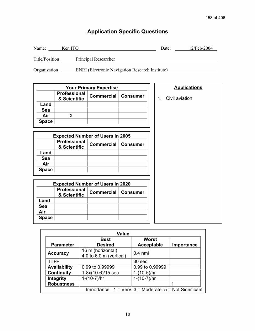
Application Specific Questions
Name: Ken ITO Date: 12/Feb/2004
Title/Position Principal Researcher
Organization ENRI (Electronic Navigation Research Institute)
Your Primary Expertise
Professional& Scientific
Commercial Consumer
Land
Sea
Air X
Space
Expected Number of Users in 2005
Professional& Scientific
Commercial Consumer
Land
Sea
Air
Space
Expected Number of Users in 2020
Professional& Scientific
Commercial Consumer
Land
Sea
Air
Space
Applications
1. Civil aviation
Value
ParameterBest
DesiredWorst
Acceptable Importance
Accuracy16 m (horizontal) 4.0 to 6.0 m (vertical)
0.4 nmi
TTFF 30 sec
Availability 0.99 to 0.99999 0.99 to 0.99999
Continuity 1-8x(10-6)/15 sec 1-(10-5)/hr
Integrity 1-(10-7)/hr 1-(10-7)/hr
Robustness 1
Importance: 1 = Very, 3 = Moderate, 5 = Not Significant
10
158 of 406

Intentionally Left Blankto Separate Responses
The Following is Reference # 7
159 of 406

L1C Questionnaire
Name: Takeyasu Sakai Date: 2/12/04
Title/Position Researcher
Organization Electronic Navigation Research Institute
Address 7-42-23 Jindaiji-Higashi, Chofu-shi, Tokyo 182-0012
Phone: +81-422-41-3194 E-Mail: [email protected]
Circle Preferences:
What new messages: Ionospheric Corrections.
Integrity Information for Public Transportation.
Messaging space allowing regional governments to broadcast
serious disaster/wheather information to their nations.
Comments:
Signature:
For Attribution?: Your Name: Yes No Your Organization: Yes No
11
160 of 406

Intentionally Left Blankto Separate Responses
The Following is Reference # 8
161 of 406

1
L1 Modernization Project (L1C) ION GPS/GNSS 2003
Portland, Oregon; September 10-12, 2003
Purpose
To solicit comments from civil and other GPS stakeholders about:
Whether or not a modernized GPS L1 civil signal should be added - and, if so -
What types of modernization would be most valuable, and why
The U.S. Government has not yet determined whether a modernized GPS L1 civil signal should be added
Why Modernize? L1 C/A is Excellent
L1 C/A works well; it supports millions of users
Accuracy is astounding
Absolute accuracy is a few meters (good for most users)
Differential navigation can give sub-meter accuracy
Surveyors and scientists rely upon sub-centimeter differential results
Interference is minimal
It’s being used for safety-of-life navigation
Why consider changing anything so successful?
“If it isn’t broken, why fix it” (there’s room for improvement)
Comments
162 of 406

2
What are Opportunities for Improvement?
Any of the longer-coded L1C options would be less susceptible to narrowband interference than L1 (C/A)
Could improve cross-correlation properties:
Improve indoor or wooded area use
Increase number of satellites and code signal power without causing unacceptable self-interference
Improve receiver signal acquisition threshold
Navigation message could contain more:
Precision, flexibility, with forward error correction (FEC)
Signal tracking and data demodulation thresholds (robustness) would be better with a modernized signal
GPS III schedule presents an opportunity - requirements need to go into a CDD by Aug. 2004
Comments
Proposed Objectives
Compatible signal for legacy C/A receivers
Continue to provide the C/A code
Minimize added noise for C/A receivers
New signals with better performance than C/A
Better correlation properties (longer codes)
More signal power and better threshold tracking
Improved performance indoors and under foliage
Improved message structure, precision, etc.
Improved narrowband interference protection
Comments
Improved performance indoors
and under foliage would be most
desirable.
163 of 406

3
L1C Data Rate Tradeoff
L1C modernized data presumably will be similar to or the same as for L2C and L5
Forward error correction (FEC) also will be used
Some data rate options:
25 bps (L2C) provides data in challenged situations
Urban canyons, indoors, in wooded areas
50 bps (L5) same as C/A now
100 bps would allow additional messages (e.g., integrity warnings)
What is best for your applications?
Response
Rank: 1 = best
Importance:
10 = very important
5 = moderate
0 = not important
Data
Rate
Your
Rank Import
25 bps 1 10
50 bps 2
100 bps 3
L1C Signal Power Tradeoff
Higher power signals generally are better
Better operation in challenged circumstances (interference, wooded areas, indoors, etc..)
More precise measurements (higher SNR)
However, higher power L1C signals could slightly increase L1 C/A noise
Less than 0.5 dB, depending on the signal choice
What is best for your applications?
Response
Increase Signal Power:
Yes
Comment:
Again, for indoors and other
challenging situations
L1C Code Length Tradeoff
The C/A code length is 1,023 chips (short)
Modernized codes are at least 10 times longer
Longer codes have major advantages:
Eliminate cross-satellite interference
Reduce effect of narrowband interference
Enable more and more powerful satellite signals
But, acquisition time (per correlator) is longer
Technology now permits thousands of correlators
What is best for your applications?
Response
The L1C code normally used for
signal acquisition should be:
10,230 chips
20,460 chips
Longer
Comment:
164 of 406

4
Adding L1C Messages – Which Ones?
GPS messages are only for navigation
Added value messages might provide:
Integrity warnings of “bad” satellite signals or weather, rescue, or other NAV-related messages
What is the best integrity source ?
Ground signals, GEO satellites, RAIM, or GPS ?
With GPS plus Galileo, is RAIM sufficient ?
What is best for your applications?
Response
Should the GPS data rate be
increased to provide additional
messages?
Integrity: No
DGPS: No
Other: No
With GPS+Galileo, would
RAIM be sufficient for
integrity?
Yes
L1C Almanac & Ephemeris Precision
C/A ephemeris precision is about 1 meter
L1C ephemeris may have 1 cm precision
Is this of any benefit for your applications?
L1C “compact almanac” may be less precise than C/A to cover more satellites faster
Is this change desirable or not?
Response
Would increased precision of the
GPS ephemeris be valuable?
Yes No
Would decreased precision of
the almanac to provide more
satellites quicker be valuable?
Yes No
Your Reaction to L1C Modernization
Do you favor L1 civil signal modernization?
What are your concerns?
What are your desires?
Why?
Reaction
Favor L1 Modernization?
Yes
165 of 406

5
Respond to one of the following:
E-mail: [email protected]
FAX: 626-583-7827
Mail: L1C GPS, 525 South Wilson Ave., Pasadena, CA 91106-3212
Your Printed Name: Steve Schell
Title or Position: Mechanical Engineer
Organization: Evolution Robotics
Contact Information: 130 W. Union St. Pasadena, CA 91103
626-535-2715
Additional Comments:
166 of 406

Intentionally Left Blankto Separate Responses
The Following is Reference # 9
167 of 406

168 of 406

2
The request of the signal form is thought to vary in the application.
Our company holds the business that OEM supplies a GPS receiver to a GPS receiver to build in
our company product, and other company.
Therefore goods request client’s receiver develop necessity.
From now on, the use field of GPS will spread out all the more, and furthermore a GPS use stage
will expand.
Therefore, it is expected to increase from now on, and there is a good requirement toward low
electric current on the circuit scale/gate number/channel several prizes of the correlation vessel
that accumulates it on the IC at the same time with the cost complying with, too.
1. Signal form.
It is about to hope because demand for the new machine happens if a new signal form is decided
when it thinks from the position of us receiver manufacturer.
But, when it thinks with the client’s position, it will reply it “It is fully satisfied in positioning
place precision being used with the present goods.”
Hesitation is born with the satisfied position for the new movement.
So, let’s think from the position that advantage convenience is more found, and see it.
There are many places where it was surrounded in geographical features by a mountain, and
there are many electric wires, street trees, obstacles such as a crossing overpass sidewalk, a high
layer building in Japan.
Furthermore, it is the environment which a satellite to see in the view in arrangement of the
satellite is scarce in.
A L1 wave is used in Japan, and there are many cases that Fix isn’t made in positioning place
operation very much about RTK in the city area that does positioning place of the high precision
a little more as a result.
(I want the number of the satellite increased under the present condition “that it can be hardly
used”).
From now on, the use field of GPS spreads out all the more, and furthermore a GPS use stage
will expand, too.
Then, there is much skill law that the poor function of the GPS system is made up for with, and it
is thought the thing that comes out to the market to extend a use range.
For example, they are combination with other GNSS systems and the use of the false satellite
system.
Though a conclusion is hard to give to this question, an idea becomes necessary very much with
the code system of present L1 in the employment side.
Modernization is thought necessity when it thinks from such an aspect, too.
It thinks that you had better put a new signal on GPS III from such a thing.
2. Modulation form.
BOC (5,1) has the danger that it locks in the wrong mountain which many correlation peaks
existed in.
It may think about the algorithm of the signal search Lock Tracking newly to avoid this
danger.
169 of 406

3
If it is BOC (1,1), even present algorithm is wrong, and the danger that Lock & Tracking is very
small.
Therefore, you must make the receiver of the extreme power low cost, and L1 signal treatment is
thought the form of the signal of BOC (1,1) to be favorable.
3. Data rate.
L1 is thought that you had better provide advantage convenience because the correspondence of
25 bps is being taken into consideration with the L2 plan. Therefore, it agrees with the one that a
rate is increased.
For example, it wants the information that the extreme power hastens TTFF, and DGPS
information.
And, it wants the satellite number information that a laser reflex mirror board is carried, too.
170 of 406

171 of 406

172 of 406

173 of 406
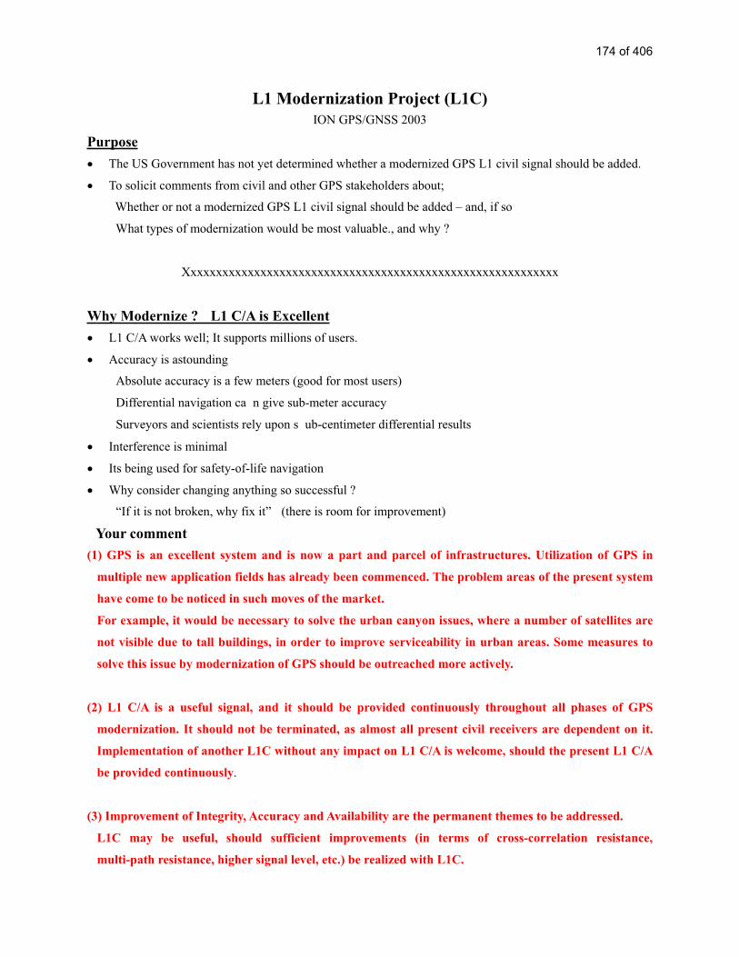
L1 Modernization Project (L1C)
ION GPS/GNSS 2003
Purpose
The US Government has not yet determined whether a modernized GPS L1 civil signal should be added.
To solicit comments from civil and other GPS stakeholders about;
Whether or not a modernized GPS L1 civil signal should be added – and, if so
What types of modernization would be most valuable., and why ?
Xxxxxxxxxxxxxxxxxxxxxxxxxxxxxxxxxxxxxxxxxxxxxxxxxxxxxxxxxxx
Why Modernize ? L1 C/A is Excellent
L1 C/A works well; It supports millions of users.
Accuracy is astounding
Absolute accuracy is a few meters (good for most users)
Differential navigation ca n give sub-meter accuracy
Surveyors and scientists rely upon s ub-centimeter differential results
Interference is minimal
Its being used for safety-of-life navigation
Why consider changing anything so successful ?
“If it is not broken, why fix it” (there is room for improvement)
Your comment
(1) GPS is an excellent system and is now a part and parcel of infrastructures. Utilization of GPS in
multiple new application fields has already been commenced. The problem areas of the present system
have come to be noticed in such moves of the market.
For example, it would be necessary to solve the urban canyon issues, where a number of satellites are
not visible due to tall buildings, in order to improve serviceability in urban areas. Some measures to
solve this issue by modernization of GPS should be outreached more actively.
(2) L1 C/A is a useful signal, and it should be provided continuously throughout all phases of GPS
modernization. It should not be terminated, as almost all present civil receivers are dependent on it.
Implementation of another L1C without any impact on L1 C/A is welcome, should the present L1 C/A
be provided continuously.
(3) Improvement of Integrity, Accuracy and Availability are the permanent themes to be addressed.
L1C may be useful, should sufficient improvements (in terms of cross-correlation resistance,
multi-path resistance, higher signal level, etc.) be realized with L1C.
174 of 406

L1C will be used and propagated, if good. Couldn't it be compatible with Galileo? Merits to users
might be greater, if L1C would be used for positioning in common with the signal provided by Galileo,
where more than 20 satellites of GPS and Galileo are visible all the time.
Xxxxxxxxxxxxxxxxxxxxxxxxxxxxxxxxxxxxxxxxxxxxxxxxxxxxxxxxxxx
What are Opportunities for Improvement ?
Any of the longer-coded L1C options would be less susceptible to narrowband interference than L1(C/A)
Could improve cross-correlation properties
Improve indoor or wooded area use
Increase number of satellites and code si gnal power without causing unacceptable self-interference
Improve receiver signal acquisition threshold
Navigation message could contain more
Precision, flexibility, wit h forward error correction (FEC)
Signal tracking and data demodulation thresholds (robustness) would be better with a modernized signal
GPS III schedule presents an opportunity - requirements need to go into a CDD by Aug. 2004
Your comment
Emphasis should not be placed on the merits too much. Instead, merits and demerits should be
weighed more on, say, longer code.
Xxxxxxxxxxxxxxxxxxxxxxxxxxxxxxxxxxxxxxxxxxxxxxxxxxxxxxxxxxx
Proposed Objectives
Compatible signal for legacy C/A receivers
Continue to provide the C/A code
Minimize added noise for C/A receivers
New signals with better performance than C/A
Better correlation properties (longer codes)
More signal power and better threshold tracking
Improved performance indoors and under foliage
Improved message structure, precision, etc
Improved narrowband interference protection
Your comment
The target values should not cause one-sided pressure on other infrastructures, including portable
phone systems.
175 of 406

Xxxxxxxxxxxxxxxxxxxxxxxxxxxxxxxxxxxxxxxxxxxxxxxxxxxxxxxxxxx
L1C Data Rate Tradeoff
L1C modernized data presumably will be similar to or the same as for L2C and L5
Forward error correction (FEC) also will be used
Some data rate options::
25 bps (L2C) provides data in challenged situations (such as urban canyons, indoors, in wooded areas)
50 bps (L5) same as C/A now
100 bps would allow additio nal messages (e.g.. Integrity warnings)
What is best for your applications ?
Response
Rank 1 = best
Importance
: 10 = very important
5 = moderate
0 = not important
xxxxxxxxxxxxxxxxxxxxxxxxxxxxxxxxxxxxxxxxxxxxxxxxxxxxxxxxxxx
L1C Signal Power Tradeoff
Higher power signals generally are better
Better operation in challenged circumstances (interference, wooded areas, indoors, etc.)
More precise measurements (higher SNR)
However, higher power L1C signals could slightly increase L1 C/A noise
Less than 0.5 dB, depending on the signal choice
What is best for your applications ?
Response
Increase Signal Power Yes
Comment
(1) The signal level must be enhanced. However, multi-channel receivers will become common- place,
when GLONASS, Galileo and other GNSS become available. Such issue should also be discussed.
(2) The signal power of L1 C/A should not be made higher than that of Block IIR, to avoid negative
impacts on the conventional receivers.
L1C should promote utilization of GPS in situations where use of present GPS is difficult.
Data Rate Your Rank Importance
25bps 1 10
50bps
100bps 1 5
176 of 406

L1C signal level may be increased, if it is feasible without causing adverse effects on the L1 C/A signal
power.
(3) However, in case the side effect of signal power enhancement is least, and in case signal(s) from other
GNSS (e.g., GLONASS, Galileo) besides GPS is/are received side by side at the analogue section of a
receiver, the same level of signal power as with those systems would be desirable.
Xxxxxxxxxxxxxxxxxxxxxxxxxxxxxxxxxxxxxxxxxxxxxxxxxxxxxxxxxxx
L1C Code Length Tradeoff
The C/A code length is 1.023 chips (short)
Modernized codes are at least 10 times longer
Longer codes have major advantages:
Eliminate cross-satellite interference
Reduce effect of narrowband interference
Enable more and more powerful satellite signals
But, acquisition time (per correlator) is longer
Technology now permits thousands of correlators
What is best for your applications ?
Response
The L1C code normally used for signal acquisition should be 10,230 chip
Comment
(1) Isn't it important to give information relative to the performance enhancement, including the change
of TTFF, should it be set at, say, ten(10) times?
(2) The size of circuit, the number of gate and the number of channel for correlator integrated in IC are
expected to be increased in the future, but there are strong demands for lower electric current on the
other hand.
In view of the electric current consumption, unlimited increase of code length will not be practical.
Accordingly, about ten (10) times the C/A code will be appropriate.
(3) The shorter the better with the signal acquisition time. However, there are some applications wherein
certain length of time is permissible on one hand, and there are some other application fields where
merits of longer code are fully utilized, on the other hand. (It is application dependent).
Xxxxxxxxxxxxxxxxxxxxxxxxxxxxxxxxxxxxxxxxxxxxxxxxxxxxxxxxxxx
177 of 406

Adding L1C Messages – Which Ones ?
GPS messages are only for navigation
Added value messages might provide
Integrity warnings of “bad” sa tellite signals or weather, rescue, or other NAV-related messages
What is the best integrity source ?
Ground signals, GEO satellites, RAIM, or GPS ?
With GPS plus Galileo, is RAIM sufficient ?
What is best for your applications?
Response
Should the GPS data rate be increased to provide additional messages
Integrity Yes
DGPS Yes
Others
With GPS + Galileo, would RAIM be sufficient for integrity
Yes
From the user stand point, rules should be established, as combines systems are likely increased in
the future.
Xxxxxxxxxxxxxxxxxxxxxxxxxxxxxxxxxxxxxxxxxxxxxxxxxxxxxxxxxxx
L1C Almanac & Ephemeris Precision
C/A ephemeris precision is about 1 meter
L1C ephemeris may have 1 cm precision
Is this of any benefit for your applications ?
L1C “compact almanac” may be less precise than C/A to cover more satellites faster
Is this change desirable or not?
Response
Would increased precision of the GPS ephemeris be valuable
Yes
Would decrease precision of the almanac to provide more satellite quicker be valuable
178 of 406

No
Your Reaction to L1C Modernization~
• Do you favor L1 civil signal modernization ?
Yes
What are your concerns ?
Enormous number of receivers with the present specification is placed in the market, and they will be
used for a prolonged period of time.
They will be used in the same environment with the receivers of new specification.
How are you going to decide the baseline standards of compatibility under such conditions?
What are your desires ?
Why ?
Respond to one of the following :
E-Mail: L1C [email protected]
Fax: +1-626-583-7827
Mail: L1C GPS, 525 South Wilson Ave., Pasadena, CA 91106-3212
Your Printed Name: Kazuaki Kakutani
Title of Position :
Organization :
Contact Information :
179 of 406

Intentionally Left Blankto Separate Responses
The Following is Reference # 10
180 of 406

L1C Questionnaire
Name: Masato Kawai Date: 2004/02/12
Title/Position Advising Research Engineer
Organization Furuno Electric Co., Ltd.
Address 9-52, Ashihara-cho, Nishinomiya-city, Hyogo, 662-8580, Japan
Phone: +81-798-63-1144 E-Mail: [email protected]
Circle Preferences:
What new messages:
(1) Forecast of signal outage on new message. (Similar to NANU information email)
(2) Toropsheric delay map like WAAS Iono-Delay Map, but with smaller grid intervals (if
possible) -> This may be done by future augmentation system.
Comments:
Nothing in particular
Signature:
For Attribution?: Your Name: Yes No Your Organization: Yes No
15
181 of 406

Intentionally Left Blankto Separate Responses
The Following is Reference # 11
182 of 406

L1C Questionnaire
Name: Tsutomu OKADA Date: 2004/02/19
Title/Position Assistant Chief
Organization Furuno Electric Co., Ltd.
Address 9-52 Ashihara-cho, Nishinomiya-shi, Hyogo 662-8580, Japan
Phone: +81-798-63-1144 E-Mail: [email protected]
Circle Preferences:
What new messages:
Interoperable messages with Galileo L1 OS signal
Comments:
I think L1C code and data rate should have interoperability with Galileo L1 OS signal. Also, faster
TTFF will be desirable. I give low priority for 25 bps because I cast GPS/IMU will displace
Assisted GPS.
Signature:
For Attribution?: Your Name: Yes No Your Organization: Yes No
16
183 of 406

Intentionally Left Blankto Separate Responses
The Following is Reference # 12
184 of 406

185 of 406

Comments:
We chose the 50bps mode to specify the effective data rate with forward error correction.
This would give us an actual bit rate of 100bps and that corresponds to 1 bit per code
length. This way we can have a better demodulation threshold and integrate over the
whole code length.
If there is an advantage to go to the 100bps(effective) rate that outweighs the ability to
integrate over the whole code length we don’t see it and would welcome any responses
on this issue.
Another possibility with the 50bps(effective) rate is not using FEC on the whole message.
What if just part of the message is FEC encoded and the other part is transmitted at
100bps. We would need some way to frame sync on the whole message, but it would be
useful to transmit ephemeris at a faster rate so the TTFF could be reduced if we have a
strong signal. In cases where the signal is weak, the ephemeris could be decoded and
verified with error correction bits. We could download multiple copies of ephemeris,
compare them, and along with the error correction bits determine where the bit errors are.
It is unclear if this would result in better thresholds but it is an idea. The advantage is
that in areas of good signal the TTFF is fast and just takes a little longer when the signal
is weak.
Thanks!
Jarrod Seymour
Garmin International
186 of 406

187 of 406

Intentionally Left Blankto Separate Responses
The Following is Reference # 13
188 of 406
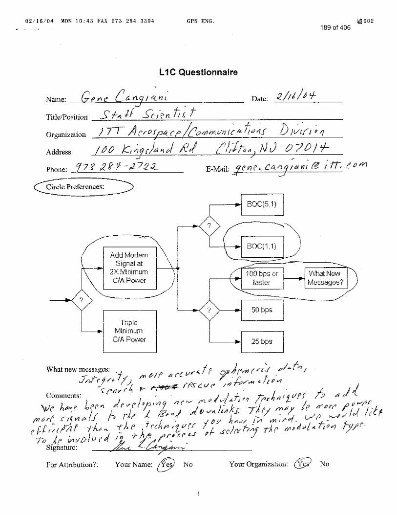
189 of 406

Intentionally Left Blankto Separate Responses
The Following is Reference # 14
190 of 406

L1C Questionnaire
Name: Date: 2004/02/12
Title/Position Associate Senior Engineer
Organization
Address
Phone: E-Mail:
Circle Preferences:
What new messages:
Comments:
Applications for indoor use will be expected to develop, so I think low data rate and more powerful
signal will be more useful in Japan.
Signature:
For Attribution?: Your Name: Yes No Your Organization: Yes No
3
191 of 406

Intentionally Left Blankto Separate Responses
The Following is Reference # 15
192 of 406

L1C Questionnaire
Name: Date: 2004/02/12
Title/Position Engineer
Organization
Address
Phone: E-Mail:
Circle Preferences:
What new messages:
Comments:
I think most GPS users like car navigation users are satisfied with present positioning accuracy.
So I want to continue the current data rate.
Signature:
For Attribution?: Your Name: Yes No Your Organization: Yes No
5
193 of 406

Intentionally Left Blankto Separate Responses
The Following is Reference # 16
194 of 406

L1C Questionnaire
Name: Satoshi Kogure Date: 2004.02.12
Title/Position Associate Senior Engineer
Organization Satellite Applications Center, Office of Space Applications, JAXA
Address 2-1-1 Sengen, Tsukuba, Ibaraki, 305-8505 JAPAN
Phone: +81-298-68-5511 E-Mail: [email protected]
Circle Preferences:
What new messages:
It is desired that L1C has enough rooms in its data message for local or regional augmentation
systems using same data message format. Integrity, disaster alarm etc. are to be added by local
operators through their own augmentation systems or L1C new NAV message.
Comments:
QZSS has a strong benefit for the users in bad circumstances such as in urban canyon and wooden
forest. If GPS L1C will enhance this characteristic, I believe that we will have great performance
for navigation by using L1C and QZSS correction data broadcasting. As for modulation method, I
hope Galileo will employ same signal structure as GPS L1C so as to facilitate to have
interoperability with GPS and QZSS.
Signature:
For Attribution?: Your Name: Yes No Your Organization: Yes No
1
195 of 406

Application Specific Questions
Name: Satoshi Kogure Date: 2004.02.12
Title/Position Associate Senior Engineer
Organization Satellite Applications Center, Office of Space Applications, JAXA
Your Primary Expertise
Professional& Scientific
Commercial Consumer
Land
Sea
Air
Space X
Expected Number of Users in 2005
Professional& Scientific
Commercial Consumer
Land 8 Millions
Sea
Air
Space
Expected Number of Users in 2020
Professional& Scientific
Commercial Consumer
Land 80 Millions
Sea
Air
Space
Applications
1. Navigation and LBS formobile users with cellular phone
2. Car navigation3. Land and maritime traffic
control
Value
ParameterBest
DesiredWorst
Acceptable Importance
Accuracy 0.5 - 1m* 1 - 3m* 2
TTFF 3
Availability 99.999% 99.99% 1
Continuity 1-10-5 /h 1-10-4/h 2
Integrity 10-7 /h* 10-6 /h* 1
Robustness 1
Importance: 1 = Very, 3 = Moderate, 5 = Not Significant* with correction data through QZSS signal
2
196 of 406

Intentionally Left Blankto Separate Responses
The Following is Reference # 17
197 of 406

L1C Questionnaire
Name: Date: 02/12/04
Title/Position Associate Senior Engineer
Organization
Address
Phone: E-Mail:
Circle Preferences:
What new messages:
Comments:
Signature:
For Attribution?: Your Name: Yes No Your Organization: Yes No
4
198 of 406

Intentionally Left Blankto Separate Responses
The Following is Reference # 18
199 of 406

1
L1C Questionnaire Name: Date: 06 Feb. '04
Title/Position Deputy General Manager
Organization
Address
Phone:
Circle Preferences:
What new messages: 1. Quick-repeating ephemeris (ex. less than 15 seconds) and almanac (ex. less than 6.25 minutes) 2. Other satellite's Ephemeris. Predicted ephemeris up to 12 hours later. (I will discuss this issue later.)
Comments: 1. The interference with present L1 C/A should be minimized. 2. The interference between GPS and Galileo should be minimized. 3. The items in "New L1C Signal Improvements" (P16) in the document "Improving the GPS L1 Signal (GPS III offers the Opportunity)" that is presented by Mr. Stansell on Jan. 23rd at Tokyo should be realized.
Signature:
For Attribution?: Your Name: Yes No Your Organization: Yes No
200 of 406

2
Application Specific Questions Name: Date: 06 Feb. '04
Title/Position
Organization
*1: This Number shows for Car Navigation only in Japan
Your Primary Expertise Professional& Scientific Commercial Consumer
Land - - X Sea - - X Air - - -
Space - - -
Expected Number of Users in 2005(annualy) Professional& Scientific Commercial Consumer
Land - - 2,500,000(*1)
Sea - - - Air - - -
Space - - -
Expected Number of Users in 2020(annualy) Professional& Scientific Commercial Consumer
Land - - - Sea - - - Air - - - Space - - -
Applications
1. Car Navigation 2. Marine Navigation
Value
ParameterBest
DesiredWorst
Acceptable ImportanceAccuracy X 1 TTFF 2Availability 2Continuity 2Integrity X 3Robustness 3
Importance: 1 = Very, 3 = Moderate, 5 = Not Significant
201 of 406

3
Additional Comment
1. The issue of cross-correlation There is an idea to change present C/A power to "Triple Minimum C/A Power" for L1C
modernization, we need to consider cross-correlation problem about this idea. The GPS receivers manufactured by JRC are almost installed for car navigation units.
This cross-correlation issue is going to influence the acquisition threshold level and the reacquisition threshold level of JRC GPS receivers.
If "Triple Minimum C/A Power" is adopted in the future, cross-correlation level may exceed the acquisition threshold level or the reacquisition threshold level. The acquisition and the reacquisition threshold levels are determined to consider the experimental result of receiving the satellites' signals at the fixed point. We describe the diagram of receiving the satellites' signals at the open sky fixed point in Figure 1.
Figure 1 Equipments for measurement
We received GPS signals over 48 hours using equipments in Figure 1. We confirmed that the maximum receiving signal power was -117dBm during that measurement. Meanwhile the maximum cross-correlation is -21.6dB(*2). Then we decided to set the acquisition and thereacquisition threshold at -137dBm that is 20dB lower than -117dBm. If the radiation power of L1 C/A triples, the receiving power will increase by 4.77dB, thenthe cross-correlation power of strong signals will exceed our acquisition and reacquisition threshold. JRC's GPS receivers may occur the positioning error often in such situation. JRC has produced GPS receivers for car navigation over six million at January, 2004. So, if the idea of "Triple C/A power" is put into operation, a lot of GPS users may be thrown into serious confusion. Therefore, we wish to be adopted the other idea instead of "Triple C/A power." The way we decided our acquisition and reacquisition threshold is confidential. Please keep it to yourself.
*2: J.J.Spilker,GPS Signal Structure and Performance Characteristics, Global Positioning System Volume I, Institute of Navigation, p46
GPS ANTENNA with LNA (open sky on the roof of the building)
JRC GPS RECEIVER
POWER SUPPLY
P.C
us
our
Our
We have
202 of 406

4
2. The issue of transmitting ephemeris data In case of adopting the method of over 100 bps transmitting rate of navigation data, we hope that the other satellite's ephemeris data will be transmitted from some satellite.
The purpose are described as follows.
1) We have the intention to prolong the period that the ephemeris data are valid for the hot start operation of GPS receivers. We think that this period is about 4 hours from the power off. But we hope that this period will be prolonged 8 or 12 hours later from power off.
2) If GPS receiver acquires the other satellites' ephemeris data(These ephemeris data haven't necessarily 2 cm accuracy to be aimed about L1C) and these ephemeris data are available in the future for example the data are available 8 hours or 12 hours later, there will be high possibility to get hot start operation at the time when GPS receivers are powered on 8 or 12 hours later because already acquired ephemeris data will be available at this moment.
According to this reason, GPS receivers are going to make progress about the availability and usefulness for car navigation application.
3. The reason of BOC(5,1) we chose We chose it because it will be able to minimize the interference with present L1 C/A.
203 of 406

L1 Modernization Project (L1C) ION GPS/GNSS 2003
Purpose
The US Government has not yet determined whether a modernized GPS L1 civil signal should be added.
To solicit comments from civil and other GPS stakeholders about;
Whether or not a modernized GPS L1 civil signal should be added – and, if so
What types of modernization would be most valuable., and why ?
Xxxxxxxxxxxxxxxxxxxxxxxxxxxxxxxxxxxxxxxxxxxxxxxxxxxxxxxxxxx
Why Modernize ? L1 C/A is Excellent
L1 C/A works well; It supports millions of users.
Accuracy is astounding
Absolute accuracy is a few meters (good for most users)
Differential navigation can give sub-meter accuracy
Surveyors and scientists rely upon sub-centimeter differential results
Interference is minimal
Its being used for safety-of-life navigation
Why consider changing anything so successful ?
“If it is not broken, why fix it” (there is room for improvement)
Your comment
L1 C/A signal has a number of application fields where it is used with full satisfaction in terms of
accuracy. Accordingly, continued utilization in the future should be guaranteed by warranting the
presently functional system.
In addition, L1 C/A dependant receiver is suitable for low priced, compact sized and low power
consuming products due to its attributes including comparatively easy signal acquisition and simple
structures.
It is anticipated that the receiver will be utilized readily in the current application fields and future
fields where L1 C/A accuracy will fully meet the requirements. For instance, L1 C/A signal is now just
like Real Time Clock (RTC) incorporated in almost all home electric appliances.
Thus, the new signal structure should ensure continued use of L1 C/A, even upon realization of L1C
signal under new GPS due to the reasons as explained above. Besides, higher accuracy and sensitivity
than those with the conventional L1 C/A signal are looked for with L1C.
204 of 406
Xxxxxxxxxxxxxxxxxxxxxxxxxxxxxxxxxxxxxxxxxxxxxxxxxxxxxxxxxxx
What are Opportunities for Improvement ?
Any of the longer-coded L1C options would be less susceptible to narrowband interference than L1(C/A)
Could improve cross-correlation properties
Improve indoor or wooded area use
Increase number of satellites and code signal power without causing unacceptable self-interference
Improve receiver signal acquisition threshold
Navigation message could contain more
Precision, flexibility, with forward error correction (FEC)
Signal tracking and data demodulation thresholds (robustness) would be better with a modernized signal
GPS III schedule presents an opportunity - requirements need to go into a CDD by Aug. 2004
Your comment
Improvements of signal acquisition sensitivity (tracking, acquisition, data demodulation), cross-
correlation performance and accuracy are hoped for.
Xxxxxxxxxxxxxxxxxxxxxxxxxxxxxxxxxxxxxxxxxxxxxxxxxxxxxxxxxxx
Proposed Objectives
Compatible signal for legacy C/A receivers
Continue to provide the C/A code
Minimize added noise for C/A receivers
New signals with better performance than C/A
Better correlation properties (longer codes)
More signal power and better threshold tracking
Improved performance indoors and under foliage
Improved message structure, precision, etc
Improved narrowband interference protection
Your comment
Higher signal power and improvement of accuracy are wanted.
Additional message-less signal is wanted to lower the threshold level of acquisition sensitivity.
Xxxxxxxxxxxxxxxxxxxxxxxxxxxxxxxxxxxxxxxxxxxxxxxxxxxxxxxxxxx
205 of 406

L1C Data Rate Tradeoff
L1C modernized data presumably will be similar to or the same as for L2C and L5
Forward error correction (FEC) also will be used
Some data rate options::
25 bps (L2C) provides data in challenged situations (such as urban canyons, indoors, in wooded areas)
50 bps (L5) same as C/A now
100 bps would allow additional messages (e.g.. Integrity warnings)
What is best for your applications ?
Response
Rank 1 = best
Importance
: 10 = very important
5 = moderate
0 = not important
xxxxxxxxxxxxxxxxxxxxxxxxxxxxxxxxxxxxxxxxxxxxxxxxxxxxxxxxxxx
L1C Signal Power Tradeoff
Higher power signals generally are better
Better operation in challenged circumstances (interference, wooded areas, indoors, etc.)
More precise measurements (higher SNR)
However, higher power L1C signals could slightly increase L1 C/A noise
Less than 0.5 dB, depending on the signal choice
What is best for your applications ?
Response
Increase Signal Power Yes
Comment
Higher sensitivity may be achieved, should there be a pilot signal without data modulation along with
enhanced signal power. Thus, addition of pilot signal without data modulation is requested
Xxxxxxxxxxxxxxxxxxxxxxxxxxxxxxxxxxxxxxxxxxxxxxxxxxxxxxxxxxx
Data Rate Your Rank Importance 25bps 0
50bps 5
100bps 1 10
206 of 406
L1C Code Length Tradeoff
The C/A code length is 1.023 chips (short)
Modernized codes are at least 10 times longer
Longer codes have major advantages:
Eliminate cross-satellite interference
Reduce effect of narrowband interference
Enable more and more powerful satellite signals
But, acquisition time (per correlator) is longer
Technology now permits thousands of correlators
What is best for your applications ?
Response
The L1C code normally used for signal acquisition should be 10,230 chip
Comment
A longer signal acquisition time would be required for enhanced code length, and deterioration of
TTFF becomes a matter of concern. On the other hand, a significant number of correlator might be
required to shorten TTFF.
For such reasons, about 10,230 of code length will be enough to eliminate cross correlation among the
signals-in space. Unnecessary enhancement of code length may result in complication with the receiver.
Besides, incorporation of some subtle measures (e.g., measure for an easy handover from L1 C/A code)
is requested.
Xxxxxxxxxxxxxxxxxxxxxxxxxxxxxxxxxxxxxxxxxxxxxxxxxxxxxxxxxxx
Adding L1C Messages – Which Ones ?
GPS messages are only for navigation
Added value messages might provide
Integrity warnings of “bad” satellite signals or weather, rescue, or other NAV-related messages
What is the best integrity source ?
Ground signals, GEO satellites, RAIM, or GPS ?
With GPS plus Galileo, is RAIM sufficient ?
What is best for your applications?
207 of 406

Response
Should the GPS data rate be increased to provide additional messages
Integrity Yes
DGPS Yes
Others Yes
With GPS + Galileo, would RAIM be sufficient for integrity
Yes
Xxxxxxxxxxxxxxxxxxxxxxxxxxxxxxxxxxxxxxxxxxxxxxxxxxxxxxxxxxx
L1C Almanac & Ephemeris Precision
C/A ephemeris precision is about 1 meter
L1C ephemeris may have 1 cm precision
Is this of any benefit for your applications ?
L1C “compact almanac” may be less precise than C/A to cover more satellites faster
Is this change desirable or not?
Response
Would increased precision of the GPS ephemeris be valuable
Yes
Would decrease precision of the almanac to provide more satellite quicker be valuable
Yes
Xxxxxxxxxxxxxxxxxxxxxxxxxxxxxxxxxxxxxxxxxxxxxxxxxxxxxxxxxxx
Your Reaction to L1C Modernization
Do you favor L1 civil signal modernization ?
Yes
What are your concerns ?
It is necessary to minimize adverse effects on L1 C/A code.
TTFF delay should be avoided as the result of enhanced code length..
208 of 406

What are your desires ?
Signal structure that can co-exist with L1 C/A code is wanted.
Why ?
Many users are already using L1 C/A signal in the world.
Respond to one of the following :
E-Mail: [email protected]
Fax: +1-626-583-7827
Mail: L1C GPS, 525 South Wilson Ave., Pasadena, CA 91106-3212
Your Printed Name:
Title of Position : GM Communications Equipment Division
Organization :
Contact Information :
Additional Cmments :
209 of 406

Intentionally Left Blankto Separate Responses
The Following is Reference # 19
210 of 406

1
L1C Questionnaire
Name: Dr. Hans-J ürgen Euler Date: April 7, 2004
Title/Position Leica Fellow in Research, Corporate Technology Center
Organization Leica Geosystems AG, Switzerland
Address CH-9435 Heerbrugg
Phone: +41 71 727 3388 E-Mail: Hans-J [email protected]
Circle Preferences:
What new messages:
Comments:
Signature:
For Attribution?: Your Name: Yes No Your Organization: Yes No
211 of 406

2
Application Specific Questions
Name: Dr. Hans-J ürgen Euler Date: April 7, 2004
Title/Position Leica Fellow in Research, Corporate Technology Center
Organization Leica Geosystems AG, Switzerland
Your Primary Expertise
Professional& Scientific
Commercial Consumer
Land X X
Sea
Air
Space
Expected Number of Users in 2005
Professional& Scientific
Commercial Consumer
Land
Sea
Air
Space
Expected Number of Users in 2020
Professional& Scientific
Commercial Consumer
Land
Sea
Air
Space
Applications
1. Surveying / Geodetic applications
2. Kinematic for precise vehicle tracking (1 cm) or better
3. Structural monitoring 4. Reference network
applications
Value
ParameterBest
DesiredWorst
Acceptable Importance
Accuracy X 1
TTFF X 3
Availability X 2
Continuity 3
Integrity X 2
Robustness X 2
Importance: 1 = Very, 3 = Moderate, 5 = Not Significant
212 of 406

Intentionally Left Blankto Separate Responses
The Following is Reference # 20
213 of 406

1
L1C Questionnaire
Name: Date: 07/03/04
Title/Position Senior Staff Member
Organization
Address
Phone: E-Mail:
Circle Preferences:
What new messages:
Satellite signal integrity
Comments:
Preferences:
Add modern signal at 2 x minimum C/A power
BOC (1, 1) appears to be a safe choice at this time based on both technical and political
grounds.
I expect 100 bps would be required.
214 of 406

2
The comments below pertain specifically to civil aviation navigation, a very specialized
application of GPS with stringent requirements. The number of receiver units sold may be
small, but the number of users is vast: all air travelers (that’s all of us).
In my view, the main requirements of aviation are:
assured positioning accuracy to each user (based on integrity monitoring implemented
in each receiver), and
robustness (which includes availability and continuity)
It’s a challenge to meet these requirements for precision approaches with GPS of today, even
with a dedicated and vastly expensive augmentation like WAAS. I believe it wouldn’t be a
challenge for GPS III to exceed the performance offered by GPS-WAAS. In fact, exceeding
the performance of GPS-WAAS would be a good criterion for GPS III to meet.
In order to meet the requirements stated above for precision approaches, GPS III would have
an advantage over the current system: It’d be in a position to exploit additional redundancies.
redundant systems (GPS and Galileo),
redundant satellites in each system,
redundant measurements from each satellite (at different frequencies), and
redundant differential corrections from multiple sources not required to be maintained
specifically for aviation (e.g., CORS sites and NDGPS).
With these options, it wouldn’t be a challenge for GPS III to exceed the performance of GPS-
WAAS.
RFI would continue to be a source of concern, and additional signal power and longer/faster
codes would help.
The navigation data rate of 50 bps is adequate for aviation. TTFF is not an issue, but time-to-
alarm (TTA) is, and TTA for category I precision approaches is 6 seconds. It may take 100
bps data rate from GPS satellites to match the performance of GPS-WAAS. The current fixed
format, however, must change to include different message types, FEC, and other features of
L2C and L5.
Signature:
For Attribution?: Your Name: No Your Organization: No
215 of 406

3
Application Specific Questions
Name: Date: 07/-3/04
Title/Position Senior Staff Member
Organization
Your Primary Expertise
Professional& Scientific
Commercial Consumer
Land
Sea
Air x
Space
Expected Number of Users in 2005
Professional& Scientific
Commercial Consumer
Land
Sea
Air 3000
Space
Expected Number of Users in 2020
Professional& Scientific
Commercial Consumer
Land
Sea
Air 10000
Space
Applications
1.
Value
ParameterBest
DesiredWorst
Acceptable Importance
Accuracy ~ 1 m 1
TTFF 30 s 3 min 5
Availability 0.99999 0.9999 1
Continuity 0.99999999 0.999999 1
Integrity 0.9999999 0.999999 1
Robustness 1 1 1
Importance: 1 = Very, 3 = Moderate, 5 = Not Significant
216 of 406

Intentionally Left Blankto Separate Responses
The Following is Reference # 21
217 of 406

1
L1 Modernization Project (L1C) ION GPS/GNSS 2003
Portland, Oregon; September 10-12, 2003
Purpose
To solicit comments from civil and other GPS stakeholders about:
Whether or not a modernized GPS L1 civil signal should be added - and, if so -
What types of modernization would be most valuable, and why
The U.S. Government has not yet determined whether a modernized GPS L1 civil signal should be added
Why Modernize? L1 C/A is Excellent
L1 C/A works well; it supports millions of users
Accuracy is astounding
Absolute accuracy is a few meters (good for most users)
Differential navigation can give sub-meter accuracy
Surveyors and scientists rely upon sub-centimeter differential results
Interference is minimal
It’s being used for safety-of-life navigation
Why consider changing anything so successful?
“If it isn’t broken, why fix it” (there’s room for improvement)
Comments
CA code spectral lines,
combined with other factors,
have caused a major failure of
GPS equipment in orbit. All four
GPS receivers on the Navy’ s
GFO ocean altimetry mission
were severely affected (not used
operationally) by the interplay of
the CA code and bias in the A/D
sampler.
A longer code would not have
exhibited the same problem.
218 of 406

2
What are Opportunities for Improvement?
Any of the longer-coded L1C options would be less susceptible to narrowband interference than L1 (C/A)
Could improve cross-correlation properties:
Improve indoor or wooded area use
Increase number of satellites and code signal power without causing unacceptable self-interference
Improve receiver signal acquisition threshold
Navigation message could contain more:
Precision, flexibility, with forward error correction (FEC)
Signal tracking and data demodulation thresholds (robustness) would be better with a modernized signal
GPS III schedule presents an opportunity - requirements need to go into a CDD by Aug. 2004
Comments
Improved cross-correlation
properties is especially important
when using pseudolites. It helps
to avoid an effect of the “near-
far problem”.
Could add realtime differential
correction to data to greatly
improve user accuracy and
integrity.
“Signal tracking and data
demodulation thresholds
(robustness) would be better
with a modernized signal”
Change “would be” to “could
be”.Reason: We may trade off
better accuracy, etc., for less
robustness.
Proposed Objectives
Compatible signal for legacy C/A receivers
Continue to provide the C/A code
Minimize added noise for C/A receivers
New signals with better performance than C/A
Better correlation properties (longer codes)
More signal power and better threshold tracking
Improved performance indoors and under foliage
Improved message structure, precision, etc.
Improved narrowband interference protection
Comments
Add better pseudorange
precision and lower multipath
error, both from higher chip rate
or use of BOC signals, to
objectives for new signals.
219 of 406

3
L1C Data Rate Tradeoff
L1C modernized data presumably will be similar to or the same as for L2C and L5
Forward error correction (FEC) also will be used
Some data rate options:
25 bps (L2C) provides data in challenged situations
Urban canyons, indoors, in wooded areas
50 bps (L5) same as C/A now
100 bps would allow additional messages (e.g., integrity warnings)
What is best for your applications?
Response
Rank: 1 = best
Importance:
10 = very important
5 = moderate
0 = not important
Data
Rate
Your
Rank Import
25 bps 5
50 bps 0 Redundant
to current
data
100 bps 5
0 bps 5 acquire
low-level
signals
250 bps 10 realtime
science
users
L1C Signal Power Tradeoff
Higher power signals generally are better
Better operation in challenged circumstances (interference, wooded areas, indoors, etc..)
More precise measurements (higher SNR)
However, higher power L1C signals could slightly increase L1 C/A noise
Less than 0.5 dB, depending on the signal choice
What is best for your applications?
Response
Increase Signal Power:
Yes
Comment:
Since I plan to exploit the new
signal, some more power is
better. There is a logical limit to
signal power. If the power
becomes much higher than
today’ s CA power, further
increases will not help, as the
system noise will then be
dominated by jamming from
other L1C signals, which will
also increase.
L1C Code Length Tradeoff
The C/A code length is 1,023 chips (short)
Response
The L1C code normally used for
220 of 406

4
Modernized codes are at least 10 times longer
Longer codes have major advantages:
Eliminate cross-satellite interference
Reduce effect of narrowband interference
Enable more and more powerful satellite signals
But, acquisition time (per correlator) is longer
Technology now permits thousands of correlators
What is best for your applications?
signal acquisition should be:
10,230 chips
20,460 chips
Longer
Comment:
We need to specify the code
repetition interval, which is the
period divided by the chipping
rate. One requirement I have is
that this interval be longer than
0.01 second.
221 of 406

5
Adding L1C Messages – Which Ones?
GPS messages are only for navigation
Added value messages might provide:
Integrity warnings of “bad” satellite signals or weather, rescue, or other NAV-related messages
What is the best integrity source ?
Ground signals, GEO satellites, RAIM, or GPS ?
I suggest GPS receivers on a few LEOs for 24 hr global integrity
monitor.
With GPS plus Galileo, is RAIM sufficient ?
What is best for your applications?
Response
Should the GPS data rate be
increased to provide additional
messages?
Integrity: No
DGPS: Yes mainly for
added accuracy
Other: Yes No
With GPS+Galileo, would
RAIM be sufficient for
integrity?
Yes
My applications benefit most
from transmitting DGPS
corrections via the data message
L1C Almanac & Ephemeris Precision
C/A ephemeris precision is about 1 meter
L1C ephemeris may have 1 cm precision
Is this of any benefit for your applications?
L1C “compact almanac” may be less precise than C/A to cover more satellites faster
Is this change desirable or not?
Response
Would increased precision of the
GPS ephemeris be valuable?
Yes
Would decreased precision of
the almanac to provide more
satellites quicker be valuable?
No
Your Reaction to L1C Modernization
Do you favor L1 civil signal modernization?
What are your concerns?
What are your desires? High chip rate,
Why?
Reaction
Favor L1 Modernization? Yes
concerns? Inaction could freeze
GPS into the current sub-optimal
civil signal on L1.
desires? High chip rate, high
data rate
Why? More precision, lower
multipath, improved realtime
accuracy.
222 of 406

Intentionally Left Blankto Separate Responses
The Following is Reference # 22
223 of 406

1
L1 Modernization Project (L1C) ION GPS/GNSS 2003
Portland, Oregon; September 10-12, 2003
Purpose
To solicit comments from civil and other GPS stakeholders about:
Whether or not a modernized GPS L1 civil signal should be added - and, if so -
What types of modernization would be most valuable, and why
The U.S. Government has not yet determined whether a modernized GPS L1 civil signal should be added
Why Modernize? L1 C/A is Excellent
L1 C/A works well; it supports millions of users
Accuracy is astounding
Absolute accuracy is a few meters (good for most users)
Differential navigation can give sub-meter accuracy
Surveyors and scientists rely upon sub-centimeter differential results
Interference is minimal
It’s being used for safety-of-life navigation
Why consider changing anything so successful?
“If it isn’t broken, why fix it” (there’s room for improvement)
Comments
Current implementation is
adequete for Shuttle.
224 of 406

2
What are Opportunities for Improvement?
Any of the longer-coded L1C options would be less susceptible to narrowband interference than L1 (C/A)
Could improve cross-correlation properties:
Improve indoor or wooded area use
Increase number of satellites and code signal power without causing unacceptable self-interference
Improve receiver signal acquisition threshold
Navigation message could contain more:
Precision, flexibility, with forward error correction (FEC)
Signal tracking and data demodulation thresholds (robustness) would be better with a modernized signal
GPS III schedule presents an opportunity - requirements need to go into a CDD by Aug. 2004
Comments
Slight benefit
Slight benefit
Slight benefit
Slight benefit
Proposed Objectives
Compatible signal for legacy C/A receivers
Continue to provide the C/A code
Minimize added noise for C/A receivers
New signals with better performance than C/A
Better correlation properties (longer codes)
More signal power and better threshold tracking
Improved performance indoors and under foliage
Improved message structure, precision, etc.
Improved narrowband interference protection
Comments
Would degrade current
MAGR-S C/A signal by ~ 0.5 dB
Slight benefit
225 of 406

3
L1C Data Rate Tradeoff
L1C modernized data presumably will be similar to or the same as for L2C and L5
Forward error correction (FEC) also will be used
Some data rate options:
25 bps (L2C) provides data in challenged situations
Urban canyons, indoors, in wooded areas
50 bps (L5) same as C/A now
100 bps would allow additional messages (e.g., integrity warnings)
What is best for your applications?
Response
Rank: 1 = best
Importance:
10 = very important
5 = moderate
0 = not important
Data
Rate
Your
Rank Import
25 bps 0
50 bps 5
100 bps 1 10
L1C Signal Power Tradeoff
Higher power signals generally are better
Better operation in challenged circumstances (interference, wooded areas, indoors, etc..)
More precise measurements (higher SNR)
However, higher power L1C signals could slightly increase L1 C/A noise
Less than 0.5 dB, depending on the signal choice
What is best for your applications?
Response
Increase Signal Power:
Yes or No
Comment: Shuttle MAGR
currently has good signal
reception; don’ t really need to
improve. Would cause 0.5 dB
degradation to current.
L1C Code Length Tradeoff
The C/A code length is 1,023 chips (short)
Modernized codes are at least 10 times longer
Longer codes have major advantages:
Eliminate cross-satellite interference
Reduce effect of narrowband interference
Enable more and more powerful satellite signals
But, acquisition time (per correlator) is longer
Technology now permits thousands of correlators
What is best for your applications?
Response
The L1C code normally used for
signal acquisition should be:
10,230 chips
20,460 chips
Longer
Comment:
Quick acquistion is important for
Shuttle; more difficult at orbital
speeds.
226 of 406

4
Adding L1C Messages – Which Ones?
GPS messages are only for navigation
Added value messages might provide:
Integrity warnings of “bad” satellite signals or weather, rescue, or other NAV-related messages
What is the best integrity source ?
Ground signals, GEO satellites, RAIM, or GPS ?
With GPS plus Galileo, is RAIM sufficient ?
What is best for your applications?
Response
Should the GPS data rate be
increased to provide additional
messages?
Integrity: Yes No
DGPS: Yes No
Other: Yes No
With GPS+Galileo, would
RAIM be sufficient for
integrity?
Yes No
L1C Almanac & Ephemeris Precision
C/A ephemeris precision is about 1 meter
L1C ephemeris may have 1 cm precision
Is this of any benefit for your applications?
L1C “compact almanac” may be less precise than C/A to cover more satellites faster
Is this change desirable or not?
Response
Would increased precision of the
GPS ephemeris be valuable?
Yes No
Possibly would allow precision
landings w/o MSBLS?
Would decreased precision of
the almanac to provide more
satellites quicker be valuable?
Yes No
Probably not due to difficulty
acquiring SV’ s at orbital speeds
Your Reaction to L1C Modernization
Do you favor L1 civil signal modernization?
What are your concerns?
What are your desires?
Why?
Reaction
Favor L1 Modernization?
Yes No
Probably not much benefit for
Shuttle, because would require
new receiver in order to take
advantage of.
227 of 406

Intentionally Left Blankto Separate Responses
The Following is Reference # 23
228 of 406

229 of 406

Intentionally Left Blankto Separate Responses
The Following is Reference # 24
230 of 406

231 of 406

Intentionally Left Blankto Separate Responses
The Following is Reference # 25
232 of 406

233 of 406

234 of 406

Intentionally Left Blankto Separate Responses
The Following is Reference # 26
235 of 406

L1 Modernization Project (L1C)
ION GPS/GNSS 2003
Purpose
The US Government has not yet determined whether a modernized GPS L1 civil signal should be added.
To solicit comments from civil and other GPS stakeholders about;
Whether or not a modernized GPS L1 civil signal should be added – and, if so
To be added
What types of modernization would be most valuable., and why ?
As to the coding of GPS messages, please make the deletion of ambiguity from the repeated use of 1 ms
PRN code easier by using Hoffman Code, etc. Also, please make arrangements so that necessary data
would be provided to users quickly through, for instance, adoption of CRC in the message code, or by
making the message structure more flexible..
Xxxxxxxxxxxxxxxxxxxxxxxxxxxxxxxxxxxxxxxxxxxxxxxxxxxxxxxxxxx
Why Modernize ? L1 C/A is Excellent
L1 C/A works well; It supports millions of users.
Accuracy is astounding
Absolute accuracy is a few meters (good for most users)
Differential navigation ca n give sub-meter accuracy
Surveyors and scientists rely upon s ub-centimeter differential results
Interference is minimal
Its being used for safety-of-life navigation
Why consider changing anything so successful ?
“If it is not broken, why fix it” (there is room for improvement)
Your comment
L1 signal is sufficiently useful, but there remains a room for improvement.
Xxxxxxxxxxxxxxxxxxxxxxxxxxxxxxxxxxxxxxxxxxxxxxxxxxxxxxxxxxx
What are Opportunities for Improvement ?
Any of the longer-coded L1C options would be less susceptible to narrowband interference than L1(C/A)
Could improve cross-correlation properties
Improve indoor or wooded area use
Increase number of satellites and code si gnal power without causing unacceptable self-interference
Improve receiver signal acquisition threshold
236 of 406

Navigation message could contain more
Precision, flexibility, wit h forward error correction (FEC)
Signal tracking and data demodulation thresholds (robustness) would be better with a modernized signal
GPS III schedule presents an opportunity - requirements need to go into a CDD by Aug. 2004
Your comment
L5 is longer-coded, and L2 is planned in a longer-code. So, no more longer-code is required. Instead,
the same level with the present L1 will be enough in view of quick initial acquisition. Much is expected
of the flexibility of navigation message format.
Besides, message code with CRC, etc. is also looked for. Transmission of modernized L1 signal from
GPS- is looked for..
Xxxxxxxxxxxxxxxxxxxxxxxxxxxxxxxxxxxxxxxxxxxxxxxxxxxxxxxxxxx
Proposed Objectives
Compatible signal for legacy C/A receivers
Continue to provide the C/A code
Minimize added noise for C/A receivers
New signals with better performance than C/A
Better correlation properties (longer codes)
More signal power and better threshold tracking
Improved performance indoors and under foliage
Improved message structure, precision, etc
Improved narrowband interference protection
Your comment
Signal and message structure compatible with the conventional C/A code receivers and improvement
of accuracy are looked for. .
Xxxxxxxxxxxxxxxxxxxxxxxxxxxxxxxxxxxxxxxxxxxxxxxxxxxxxxxxxxx
L1C Data Rate Tradeoff
L1C modernized data presumably will be similar to or the same as for L2C and L5
Forward error correction (FEC) also will be used
Some data rate options::
25 bps (L2C) provides data in challenged situations (such as urban canyons, indoors, in wooded areas)
50 bps (L5) same as C/A now
237 of 406

100 bps would allow additio nal messages (e.g.. Integrity warnings)
What is best for your applications ?
Response
Rank 1 = best
Importance
: 10 = very important
5 = moderate
0 = not important
xxxxxxxxxxxxxxxxxxxxxxxxxxxxxxxxxxxxxxxxxxxxxxxxxxxxxxxxxxx
L1C Signal Power Tradeoff
Higher power signals generally are better
Better operation in challenged circumstances (interference, wooded areas, indoors, etc.)
More precise measurements (higher SNR)
However, higher power L1C signals could slightly increase L1 C/A noise
Less than 0.5 dB, depending on the signal choice
What is best for your applications ?
Response
Increase Signal Power Yes
Comment
Slightly stronger signal would be preferable
Xxxxxxxxxxxxxxxxxxxxxxxxxxxxxxxxxxxxxxxxxxxxxxxxxxxxxxxxxxx
L1C Code Length Tradeoff
The C/A code length is 1.023 chips (short)
Modernized codes are at least 10 times longer
Longer codes have major advantages:
Eliminate cross-satellite interference
Reduce effect of narrowband interference
Enable more and more powerful satellite signals
But, acquisition time (per correlator) is longer
Technology now permits thousands of correlators
What is best for your applications ?
Data Rate Your Rank Importance
25bps 3 0
50bps 2 5
100bps 1 10
238 of 406

Response
The L1C code normally used for signal acquisition should be 10,230 chip
Comment
We are developing GPS receivers for use in space. The signal acquisition in the vast space is a subject
requiring intensive studies. Besides, the receiver being for space applications, thousands of correlator
cannot be incorporated. For this reason, merits of modernized L1 signal may not be available to us,
should the chip length be made longer..
Xxxxxxxxxxxxxxxxxxxxxxxxxxxxxxxxxxxxxxxxxxxxxxxxxxxxxxxxxxx
Adding L1C Messages – Which Ones ?
GPS messages are only for navigation
Added value messages might provide
Integrity warnings of “bad” sa tellite signals or weather, rescue, or other NAV-related messages
What is the best integrity source ?
Ground signals, GEO satellites, RAIM, or GPS ?
With GPS plus Galileo, is RAIM sufficient ?
What is best for your applications?
Response
Should the GPS data rate be increased to provide additional messages
Integrity Yes
DGPS Yes
Others
With GPS + Galileo, would RAIM be sufficient for integrity
No
GPS signal only may be received. In such event, it is preferable to have integrity
data incorporated in GPS signal
Xxxxxxxxxxxxxxxxxxxxxxxxxxxxxxxxxxxxxxxxxxxxxxxxxxxxxxxxxxx
L1C Almanac & Ephemeris Precision
C/A ephemeris precision is about 1 meter
L1C ephemeris may have 1 cm precision
Is this of any benefit for your applications ?
239 of 406

L1C “compact almanac” may be less precise than C/A to cover more satellites faster
Is this change desirable or not?
Response
Would increased precision of the GPS ephemeris be valuable
No
Would decrease precision of the almanac to provide more satellite quicker be valuable
No
Instead, please study the method of quicker Almanac broadcasting in the efforts for
flexible message format structure.
Xxxxxxxxxxxxxxxxxxxxxxxxxxxxxxxxxxxxxxxxxxxxxxxxxxxxxxxxxxx
Your Reaction to L1C Modernization
Do you favor L1 civil signal modernization ?
Yes
What are your concerns ?
Emphasis on the usefulness of long code is enough to cause concerns for possible termination of short
code.
What are your desires ?
Modernization of message is specifically looked for, while maintaining the conventional short code.
Why ?
Short signal acquisition time is to be maintained by continued use of short code.
Error of 1 ms code cycle is to be eliminated by Hoffman coding of messages (in the same manner
with the L5C messages).
Information such as Almanac is to be acquired quickly by flexible message format.
Inclusion of Integrity data and DGPS data in messages is expected.
Respond to one of the following :
240 of 406

E-Mail: [email protected]
Fax: +1-626-583-7827
Mail: L1C GPS, 525 South Wilson Ave., Pasadena, CA 91106-3212
Your Printed Name: Hiroaki Maeda
Title of Position : Assistant Manager, Satellite Solutions Planning Group
Organization : NEC Toshiba Space
Contact Information : maeda.hiroaki@ntspace. jp
Additional Cmments :
241 of 406

Intentionally Left Blankto Separate Responses
The Following is Reference # 27
242 of 406

L1C Questionnaire
Name: Takeshi Ono Date: Feb.10th.2004
Title/Position Engineering Manager
Organization NEC Toshiba Space Systems Ltd.
Address 4035 Ikebe-cho Tsuzuki-ku Yokohama Japan
Phone: +81-45-938-8345 E-Mail: [email protected]
Circle Preferences:
What new messages:
Precise Ionosphere Correction Message
Integrity message
Comments:
Satellite anomaly should be broadcast immediately via message.
Signature:
For Attribution?: Your Name: Yes No Your Organization: Yes No
12
243 of 406

Application Specific Questions
Name: Takeshi Ono Date: Feb.10th.2004
Title/Position Engineering Manager
Organization NEC Toshiba Space Systems Ltd.
Your Primary Expertise
Professional& Scientific
Commercial Consumer
Land X
Sea
Air
Space X
Expected Number of Users in 2005
Professional& Scientific
Commercial Consumer
Land 2000000
Sea
Air
Space 50
Expected Number of Users in 2020
Professional& Scientific
Commercial Consumer
Land 10000000
Sea
Air
Space 100
Applications
1. Time transfer Receiver 2. Satellite Orbit
Determination3. Ionosphere and
troposphere observationreceiver
Value
ParameterBest
DesiredWorst
Acceptable Importance
Accuracy 1m 10m 1
TTFF 180sec 60sec 2
Availability 99.999% 99.99% 2
Continuity 1-10-5 /h 1-10-4/h 2
Integrity 10-7 /h 10-6 /h 1
Robustness 2
Importance: 1 = Very, 3 = Moderate, 5 = Not Significant
13
244 of 406

Intentionally Left Blankto Separate Responses
The Following is Reference # 28
245 of 406

L1C Questionnaire
Name: Kazumi Sagawa Date: Feb.18th.2004
Title/Position Engineering Manager
Organization NEC Toshiba Space Systems Ltd.
Address 4035 Ikebe-cho Tsuzuki-ku Yokohama Japan
Phone: +81-45-938-8242 E-Mail: [email protected]
Circle Preferences:
What new messages:
Comments:
A necessary data rate may be sufficient for the GPS in 25bps.
But, the EIRP had better be big so that it will be able to expand it like SBAS.
Signature:
For Attribution?: Your Name: Yes No Your Organization: Yes No
14
246 of 406

Intentionally Left Blankto Separate Responses
The Following is Reference # 29
247 of 406

Date: Fri, 19 Dec 2003 14:23:45 -0500From: "Dennis Milbert" <[email protected]>To: [email protected]: [email protected], Dennis Milbert <[email protected]>, Charlie Challstrom <[email protected]>, [email protected]: NGS comments on L1 Modernization
Dear Tom,
Thanks again for the briefing. Here are our comments =====================================================
Responses to L1C Questionnaire:
Based on the the collected comments and discussion at the meeting, the following is the National Geodetic Survey, NOS, NOAA response. We note that other elements in NOS and in NOAA may have similar or differing viewpoints.
We prefer a modernized L1C signal. This would give the opportunity to provide a data-less signal component that would have useful carrier phase tracking properties.
We have no preference regarding BOC(1,1) vs. BOC(5,1). We are primarily interested in accurate carrier phase and ambiguity resolution. Pseudorange (PR) accuracy is a secondary, albeit, important item. Neither signal type has a major PR difference, particularly if narrow correlator multipath supression technology is utilized.
We have no preference regarding message bit rate.
We have no preference regarding new messages. We will be operating in a multifrequency mode, so L2C and L5 messaging will be available. We will have access to the messages on those channels.
The general comments from our group:
More robustness against cycle slips would be welcome.
Current signal options show no improvement to ambiguity resolution -- makes discussion less interesting.
Calibration of satellite antenna phase centers to center of mass of the satellite is crucial.
248 of 406

Calibration of signals, possibly permitting undifferenced ambiguity resolution would be very interesting.
Respectfully submitted,
Dr. Dennis G. Milbert Chief Geodesist NOAA, National Geodetic Survey, N/NGS 1315 East-West Hwy., SSMC3, Room 8635 Silver Spring, MD 20910-3282
phone: 301-713-3222 x144 fax: 301-713-4315 internet: [email protected]
249 of 406

Intentionally Left Blankto Separate Responses
The Following is Reference # 30
250 of 406

L1C Questionnaire
Name: Toshiaki Iwata Date: 2004/02/12
Title/Position Senior Research Scientist
Organization
Address
Phone: +81-29-861-5706 E-Mail:
Circle Preferences:
What new messages: the difference among GPS time, UTC(CRL) and UTC(NMIJ)
Comments:
Signature:
For Attribution?: Your Name: Yes No Your Organization: Yes No
7
251 of 406

Application Specific Questions
Name: Toshiaki Iwata Date: 2004/02/12
Title/Position Senior Research Scientist
Organization
Your Primary Expertise
Professional& Scientific
Commercial Consumer
Land
Sea
Air
Space
Expected Number of Users in 2005
Professional& Scientific
Commercial Consumer
Land 10
Sea
Air
Space
Expected Number of Users in 2020
Professional& Scientific
Commercial Consumer
Land 10000
Sea
Air
Space
Applications
1. Synchronization ofdistributed power supply.
2. Locational identificationof distributed power supply.
Value
ParameterBest
DesiredWorst
Acceptable Importance
Accuracy
TTFF
Availability
Continuity
Integrity
Robustness
Importance: 1 = Very, 3 = Moderate, 5 = Not Significant
8
252 of 406

Intentionally Left Blankto Separate Responses
The Following is Reference # 31
253 of 406

L1 Modernization Project (L1C)
ION GPS/GNSS 2003
Purpose
The US Government has not yet determined whether a modernized GPS L1 civil signal should be added.
To solicit comments from civil and other GPS stakeholders about;
Whether or not a modernized GPS L1 civil signal should be added – and, if so
What types of modernization would be most valuable., and why ?
Xxxxxxxxxxxxxxxxxxxxxxxxxxxxxxxxxxxxxxxxxxxxxxxxxxxxxxxxxxx
Why Modernize ? L1 C/A is Excellent
L1 C/A works well; It supports millions of users.
Accuracy is astounding
Absolute accuracy is a few meters (good for most users)
Differential navigation ca n give sub-meter accuracy
Surveyors and scientists rely upon s ub-centimeter differential results
Interference is minimal
Its being used for safety-of-life navigation
Why consider changing anything so successful ?
“If it is not broken, why fix it” (there is room for improvement)
Your comment
My personal basic conception is such that the full compatibility with the conventional C/A code
(meaning that the present code can be used without any change) should be the major premise of the
proposed change. If it is not feasible, the signal change should be abandoned regardless of the
development expenditures, because the impact on the end users is infinite..
Xxxxxxxxxxxxxxxxxxxxxxxxxxxxxxxxxxxxxxxxxxxxxxxxxxxxxxxxxxx
What are Opportunities for Improvement ?
Any of the longer-coded L1C options would be less susceptible to narrowband interference than L1(C/A)
Could improve cross-correlation properties
Improve indoor or wooded area use
Increase number of satellites and code si gnal power without causing unacceptable self-interference
Improve receiver signal acquisition threshold
Navigation message could contain more
Precision, flexibility, wit h forward error correction (FEC)
254 of 406

Signal tracking and data demodulation thresholds (robustness) would be better with a modernized signal
GPS III schedule presents an opportunity - requirements need to go into a CDD by Aug. 2004
Your comment
Comments on the foregoing are as follows:
Enhancement of cross-correlation performance will be valuable. It may be effective for removal of
multi-path.
Effectiveness for indoor or wooded area performance and interference signal resistance remains
uncertain. However, improvement of code-chip rate will contribute much to downsizing of equipments
and is wished for under the context.
Shorter navigation message is preferable for improvement of cold-start performance by quick
acquisition of Ephemeris.
The merits of robustness to actual users remain uncertain at present. Needless to say, it would be
important to make adjustment with the GPS schedule .
Xxxxxxxxxxxxxxxxxxxxxxxxxxxxxxxxxxxxxxxxxxxxxxxxxxxxxxxxxxx
Proposed Objectives
Compatible signal for legacy C/A receivers
Continue to provide the C/A code
Minimize added noise for C/A receivers
New signals with better performance than C/A
Better correlation properties (longer codes)
More signal power and better threshold tracking
Improved performance indoors and under foliage
Improved message structure, precision, etc
Improved narrowband interference protection
Your comment
Promotion of L1C is agreeable, if a higher priority is placed on the existing C/A code users. Comments
on other points are omitted here, as they are already mentioned above.
Xxxxxxxxxxxxxxxxxxxxxxxxxxxxxxxxxxxxxxxxxxxxxxxxxxxxxxxxxxx
255 of 406

L1C Data Rate Tradeoff
L1C modernized data presumably will be similar to or the same as for L2C and L5
Forward error correction (FEC) also will be used
Some data rate options::
25 bps (L2C) provides data in challenged situations (such as urban canyons, indoors, in wooded areas)
50 bps (L5) same as C/A now
100 bps would allow additio nal messages (e.g.. Integrity warnings)
What is best for your applications ?
Response
Rank 1 = best
Importance
: 10 = very important
5 = moderate
0 = not important
xxxxxxxxxxxxxxxxxxxxxxxxxxxxxxxxxxxxxxxxxxxxxxxxxxxxxxxxxxx
L1C Signal Power Tradeoff
Higher power signals generally are better
Better operation in challenged circumstances (interference, wooded areas, indoors, etc.)
More precise measurements (higher SNR)
However, higher power L1C signals could slightly increase L1 C/A noise
Less than 0.5 dB, depending on the signal choice
What is best for your applications ?
Response
Increase Signal Power No
Comment
A higher priority on the existing C/A code users.
There will not be any problem, even if it is not specifically high, as it has to be left to manufacturers'
efforts.
Xxxxxxxxxxxxxxxxxxxxxxxxxxxxxxxxxxxxxxxxxxxxxxxxxxxxxxxxxxx
L1C Code Length Tradeoff
The C/A code length is 1.023 chips (short)
Modernized codes are at least 10 times longer
Data Rate Your Rank Importance
25bps 1 10
50bps 2 5
100bps 3 0
256 of 406

Longer codes have major advantages:
Eliminate cross-satellite interference
Reduce effect of narrowband interference
Enable more and more powerful satellite signals
But, acquisition time (per correlator) is longer
Technology now permits thousands of correlators
What is best for your applications ?
Response
The L1C code normally used for signal acquisition should be 10,230 chip
Comment
About ten(10) times will be enough..
Xxxxxxxxxxxxxxxxxxxxxxxxxxxxxxxxxxxxxxxxxxxxxxxxxxxxxxxxxxx
Adding L1C Messages – Which Ones ?
GPS messages are only for navigation
Added value messages might provide
Integrity warnings of “bad” sa tellite signals or weather, rescue, or other NAV-related messages
What is the best integrity source ?
Ground signals, GEO satellites, RAIM, or GPS ?
With GPS plus Galileo, is RAIM sufficient ?
What is best for your applications?
Response
Should the GPS data rate be increased to provide additional messages
Integrity No
DGPS No
Others No
With GPS + Galileo, would RAIM be sufficient for integrity
Yes
Necessity of additional message is unclear in terms of effects and importance for user friendliness.
The ground base signal may serve for Integrity.
Xxxxxxxxxxxxxxxxxxxxxxxxxxxxxxxxxxxxxxxxxxxxxxxxxxxxxxxxxxx
257 of 406

L1C Almanac & Ephemeris Precision
C/A ephemeris precision is about 1 meter
L1C ephemeris may have 1 cm precision
Is this of any benefit for your applications ?
L1C “compact almanac” may be less precise than C/A to cover more satellites faster
Is this change desirable or not?
Response
Would increased precision of the GPS ephemeris be valuable
No
Would decrease precision of the almanac to provide more satellite quicker be valuable
Yes
Xxxxxxxxxxxxxxxxxxxxxxxxxxxxxxxxxxxxxxxxxxxxxxxxxxxxxxxxxxx
Your Reaction to L1C Modernization
Do you favor L1 civil signal modernization ?
It is difficult to say Yes or No at present.
What are your concerns ?
Coordination with the present C/A code users is the prerequisite.
GPS modernization project itself may be delayed by too hefty ideal.
Isn't it possible to cope with L2C that is already close at hand?
What are your desires ?
Our desires as below:
Support of multi-path removal through improved correlation performance.
Short Ephemeris acquisition time through reduced length of navigation message (less than 10
seconds).
With improvement of the present 1 ms C/A code chip rate. SS frequency diffusion is increased. Thus,
development of compact-size equipment as well as development of technology to reduce positioning
interval are made easier.
258 of 406

However, the foregoing may be realized by L2C as well.
Why ?
As per the above .
Respond to one of the following :
E-Mail: [email protected]
Fax: +1-626-583-7827
Mail: L1C GPS, 525 South Wilson Ave., Pasadena, CA 91106-3212
Your Printed Name: Mitsuma C. Izawa
Title of Position : Senior Manager
Organization : Nikon-Trimble Co Ltd
Contact Information : [email protected]
Additional Cmments :
259 of 406

Intentionally Left Blankto Separate Responses
The Following is Reference # 32
260 of 406

1
L1C Questionnaire
Name: Pat Fenton on behalf of NovAtel Inc. Date: April 2,2004
Title/Position Chief Technology Officer
Organization NovAtel Inc.
Address 1120 68th
Avenue N.E., Calgary Alberta Canada
Phone: (403) 295-4539 E-Mail: [email protected]
Circle Preferences:
What new messages:
Comments:
Signature: Pat F.
For Attribution?: Your Name: Yes No Your Organization: Yes No
261 of 406

2
Application Specific Questions
Name: Pat Fenton Date: April 2,2004
Title/Position Chief Technology Officer
Organization NovAtel Inc.
Your Primary Expertise
Professional& Scientific
Commercial Consumer
Land X X
Sea X X
Air X X
Space
Expected Number of Users in 2005
Professional& Scientific
Commercial Consumer
Land X000 X0,000
Sea X0 X00
Air X0 X00
Space X
Expected Number of Users in 2020
Professional& Scientific
Commercial Consumer
Land X0,000 X,000,000
Sea X00 X0,000
Air X00 X0,000
Space X0
Applications
1. We sell cards into mostapplication areas; air,land, sea, cars, trains,UAVs, surveyinstruments, seismic, Jettrainers, Aircraft landing,takeoff, in-route,deformation monitoring,Asset tracking, Timing,Ground referencenetworks,
Value
ParameterBest
DesiredWorst
Acceptable Importance
Accuracy 0.1m 1m1 (OEM)2 (Aviation)
TTFF 60 120 3
Availability 100 99% 2
Continuity 100 99% 2
Integrity Yes1(Aviation),3 (OEM)
Robustness Yes 1
Importance: 1 = Very 3 = Moderate 5 = Not Significant
262 of 406

Intentionally Left Blankto Separate Responses
The Following is Reference # 33
263 of 406

1
L1C Questionnaire
Name: Dorota Brzezinska, Charles Toth Date: May 21, 2004
Title/Position Associate Professor, Sr. Research Scientist
Organization The Ohio State University
Address 470 Hitchcock Hall, 2070 Neil Avenue, Columbus, OH 43210-1275
Phone: 614 292-8787 E-Mail: [email protected], [email protected]
Circle Preferences:
What new messages:
Differential corrections, ionosphere in particular (it would make sense if the user receives
all the relevant information from one source), integrity information
Comments:
Expecting advances in signal processing to continue at the current pace, the implementation
of BOC(5,1) will be feasible in the planned time frame for modernization.
Signature:
264 of 406

2
For Attribution?: Your Name: Yes No Your Organization: Yes No
265 of 406

3
Application Specific Questions
Name: Dorota Brzezinska, Charles Toth Date: May 21, 2004
Title/Position Associate Professor, Sr. Research Scientist
Organization The Ohio State University
Your Primary Expertise
Professional& Scientific
Commercial Consumer
Land X
Sea
Air X
Space
Expected Number of Users in 2005
Professional& Scientific
Commercial Consumer
Land No change Growing Growing
Sea
Air No change Growing Growing
Space
Expected Number of Users in 2020
Professional& Scientific
Commercial Consumer
Land Growing 10x 10x
Sea
Air Growing 2x 2x
Space
Applications
1. Land-based mobile mapping
2. Airborne mapping 3. RTK 4. Airborne and land-based
gravimetry
Value
ParameterBest
DesiredWorst
Acceptable Importance
Accuracy cm-level dm-level 1
TTFF 5
Availability 1
Continuity 3
Integrity 3
Robustness 3
Importance: 1 = Very, 3 = Moderate, 5 = Not Significant
266 of 406

Intentionally Left Blankto Separate Responses
The Following is Reference # 34
267 of 406

1
L1C Questionnaire
Name: Michael S. Braasch Date: July 9, 2004
Title/Position: Professor of Electrical Engineering
Organization: Ohio University / Avionics Engineering Center
Address 322D Stocker Center, Ohio University, Athens, OH 45701-2979
Phone: 740-593-0105 E-Mail: [email protected]
Circle Preferences:
What new messages: NONE
Comments: A new modernized signal is highly desirable. It allows us to take advantage of many if
not all of the improvements which have been identified or implemented elsewhere. These
improvements include longer codes (which reduce various forms of interference), message
improvements and a data-free signal component. Although there are both advantages and
disadvantages associated with increased and decreased message data rates, the lower data rate (25
bps) is preferred since it extends system performance in low signal-strength environments. The
TTFF concerns can easily be eliminated simply by placing a day’s worth of ephemeris messages onto
the web and other media. Both the BOC (1,1) and the BOC (5,1) are acceptable. The BOC (5,1) is
preferred since it provides less interference both to M-code and the C/A-code and it can offer better
code-loop tracking accuracy.
268 of 406

2
Signature: Michael S. Braasch
For Attribution?: Your Name: Yes Your Organization: Yes
269 of 406

3
Application Specific Questions
Name: Michael S. Braasch Date: July 9, 2004
Title/Position Professor of Electrical Engineering
Organization Ohio University / Avionics Engineering Center
Your Primary Expertise
Professional& Scientific
Commercial Consumer
Land
Sea
Air X x x
Space
Expected Number of Users in 2005
Professional& Scientific
Commercial Consumer
Land
Sea
Air 20,000 10,000 50,000
Space
Expected Number of Users in 2020
Professional& Scientific
Commercial Consumer
Land
Sea
Air 50,000 30,000 150,000
Space
Applications
1. Guidance, navigation, and surveillance of civilian aircraft (both unmanned and manned).
270 of 406

4
Value
ParameterBest
DesiredWorst
Acceptable Importance
Accuracy Centimeter-level
20 meters (horizontal)
3
TTFF Instantaneous 2 minutes 3
Availability 100%5 minutes per day of unavailability
1
Continuity 100%
Probabilityof loss of continuityless than 1e-5 per 120 seconds
1
Integrity 100%
Probabilityof loss of integrity less than 1e-7 per hour
1
Robustness ‘bulletproof’
Needs to be no worse than the existing C/A code
1
Importance: 1 = Very, 3 = Moderate, 5 = Not Significant
271 of 406

Intentionally Left Blankto Separate Responses
The Following is Reference # 35
272 of 406

1
L1C Questionnaire
Name: Toshihiro Ishigaki Date: 26 J anuary 2004
Title/Position Staff Engineer
Organization Matsushita Electric Industrial Co.,Ltd. Panasonic Automotive Systems Company
Address 600 Saedo-cho Tsuzuki-ku Yokohama J apan
Phone: +81 45 939 1249 E-Mail: [email protected]
Circle Preferences:
What new messages:
I hope no additional messages. I want to get ephemeris faster.
Comments:
I request strongly that the impact on existing C/A receivers is negligible.
My expectations for new L1C signal are as follows.
(1) Reduce effect of interference
(2) Improve TTFF
Signature:
For Attribution?: Your Name: Yes No Your Organization: Yes No
273 of 406

2
Application Specific Questions
Name: Toshihiro Ishigaki Date: 26 J anuary 2004
Title/Position Staff Engineer
Organization Matsushita Electric Industrial Co.,Ltd. Panasonic Automotive Systems Company
Your Primary Expertise
Professional& Scientific
Commercial Consumer
Land
Sea
Air
Space
Expected Number of Users in 2005
Professional& Scientific
Commercial Consumer
Land ?
Sea
Air
Space
Expected Number of Users in 2020
Professional& Scientific
Commercial Consumer
Land ?
Sea
Air
Space
Applications
1. Car Navigation System
Value
ParameterBest
DesiredWorst
Acceptable Importance
Accuracy 3
TTFF 1
Availability 3
Continuity 1
Integrity 1
Robustness 1
Importance: 1 = Very, 3 = Moderate, 5 = Not Significant
274 of 406

L1 Modernization Project (L1C)
ION GPS/GNSS 2003
Purpose
The US Government has not yet determined whether a modernized GPS L1 civil signal should be added.
To solicit comments from civil and other GPS stakeholders about;
Whether or not a modernized GPS L1 civil signal should be added – and, if so –
To be added
What types of modernization would be most valuable., and why ?
The same signal structure as with L2C or L5 is preferable.
Reasons It is not desirable to have more number of signals with different structures .
Xxxxxxxxxxxxxxxxxxxxxxxxxxxxxxxxxxxxxxxxxxxxxxxxxxxxxxxxxxx
Why Modernize ? L1 C/A is Excellent
L1 C/A works well; It supports millions of users.
Accuracy is astounding
Absolute accuracy is a few meters (good for most users)
Differential navigation can give sub-meter accuracy
Surveyors and scientists rely upon sub-centimeter differential results
Interference is minimal
Its being used for safety-of-life navigation
Why consider changing anything so successful ?
“If it is not broken, why fix it” (there is room for improvement)
Your comment
Certainly, L1 signal is sufficiently useful at present. However, it might be felt to be outdated, when L2C
and L5 have come to be provided, especially when Galileo services have come to be commenced.
Xxxxxxxxxxxxxxxxxxxxxxxxxxxxxxxxxxxxxxxxxxxxxxxxxxxxxxxxxxx
What are Opportunities for Improvement ?
Any of the longer-coded L1C options would be less susceptible to narrowband interference than L1(C/A)
Could improve cross-correlation properties
Improve indoor or wooded area use
Increase number of satellites and code signal power without causing unacceptable self-interference
Improve receiver signal acquisition threshold
Navigation message could contain more
Precision, flexibility, with forward error correction (FEC)
Signal tracking and data demodulation thresholds (robustness) would be better with a modernized signal
GPS III schedule presents an opportunity - requirements need to go into a CDD by Aug. 2004
275 of 406
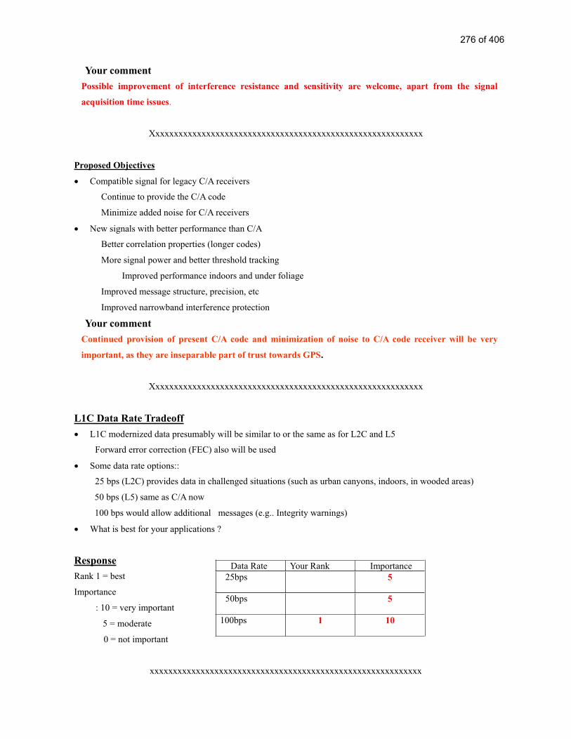
Your comment
Possible improvement of interference resistance and sensitivity are welcome, apart from the signal
acquisition time issues.
Xxxxxxxxxxxxxxxxxxxxxxxxxxxxxxxxxxxxxxxxxxxxxxxxxxxxxxxxxxx
Proposed Objectives
Compatible signal for legacy C/A receivers
Continue to provide the C/A code
Minimize added noise for C/A receivers
New signals with better performance than C/A
Better correlation properties (longer codes)
More signal power and better threshold tracking
Improved performance indoors and under foliage
Improved message structure, precision, etc
Improved narrowband interference protection
Your comment
Continued provision of present C/A code and minimization of noise to C/A code receiver will be very
important, as they are inseparable part of trust towards GPS.
Xxxxxxxxxxxxxxxxxxxxxxxxxxxxxxxxxxxxxxxxxxxxxxxxxxxxxxxxxxx
L1C Data Rate Tradeoff
L1C modernized data presumably will be similar to or the same as for L2C and L5
Forward error correction (FEC) also will be used
Some data rate options::
25 bps (L2C) provides data in challenged situations (such as urban canyons, indoors, in wooded areas)
50 bps (L5) same as C/A now
100 bps would allow additional messages (e.g.. Integrity warnings)
What is best for your applications ?
Response
Rank 1 = best
Importance
: 10 = very important
5 = moderate
0 = not important
xxxxxxxxxxxxxxxxxxxxxxxxxxxxxxxxxxxxxxxxxxxxxxxxxxxxxxxxxxx
Data Rate Your Rank Importance
25bps 5
50bps 5
100bps 1 10
276 of 406

L1C Signal Power Tradeoff
Higher power signals generally are better
Better operation in challenged circumstances (interference, wooded areas, indoors, etc.)
More precise measurements (higher SNR)
However, higher power L1C signals could slightly increase L1 C/A noise
Less than 0.5 dB, depending on the signal choice
What is best for your applications ?
Response
Increase Signal Power Yes
Comment
It is necessary to minimize the L1 C/A noise, but greater resistance against other noise sources is looked
for
Xxxxxxxxxxxxxxxxxxxxxxxxxxxxxxxxxxxxxxxxxxxxxxxxxxxxxxxxxxx
L1C Code Length Tradeoff
The C/A code length is 1.023 chips (short)
Modernized codes are at least 10 times longer
Longer codes have major advantages:
Eliminate cross-satellite interference
Reduce effect of narrowband interference
Enable more and more powerful satellite signals
But, acquisition time (per correlator) is longer
Technology now permits thousands of correlators
What is best for your applications ?
Response
The L1C code normally used for signal acquisition should be 10,230 chip
Comment
About this level would be appropriate in consideration of the signal acquisition time.
Xxxxxxxxxxxxxxxxxxxxxxxxxxxxxxxxxxxxxxxxxxxxxxxxxxxxxxxxxxx
Adding L1C Messages – Which Ones ?
GPS messages are only for navigation
Added value messages might provide
Integrity warnings of “bad” satellite signals or weather, rescue, or other NAV-related messages
What is the best integrity source ?
Ground signals, GEO satellites, RAIM, or GPS ?
With GPS plus Galileo, is RAIM sufficient ?
277 of 406

What is best for your applications?
Response
Should the GPS data rate be increased to provide additional messages
Integrity Yes
DGPS Yes
Others Yes
With GPS + Galileo, would RAIM be sufficient for integrity
No
Xxxxxxxxxxxxxxxxxxxxxxxxxxxxxxxxxxxxxxxxxxxxxxxxxxxxxxxxxxx
L1C Almanac & Ephemeris Precision
C/A ephemeris precision is about 1 meter
L1C ephemeris may have 1 cm precision
Is this of any benefit for your applications ?
L1C “compact almanac” may be less precise than C/A to cover more satellites faster
Is this change desirable or not?
Response
Would increased precision of the GPS ephemeris be valiable
Yes
Would decrease precision of the almanac to provide more satellite quicker be valiable
Yes
Xxxxxxxxxxxxxxxxxxxxxxxxxxxxxxxxxxxxxxxxxxxxxxxxxxxxxxxxxxx
Your Reaction to L1C Modernization
Do you favor L1 civil signal modernization ?
Yes
What are your concerns ?
Interference with the present C/A code and the issue of signal acquisition time
What are your desires ?
Establishment of compatibility and inter-operability with Galileo and QZSS
278 of 406

Why ?
Upon commencement of Galileo or QZSS services, they will be used side by side with GPS services in
general
Respond to one of the following :
E-Mail: [email protected]
Fax: +1-626-583-7827
Mail: L1C GPS, 525 South Wilson Ave., Pasadena, CA 91106-3212
Your Printed Name: Toshihiro Ishigaki
Title of Position : Chief Engineer, R&D Center
Organization : Matsushita, Panasonic Automotive Systems
Contact Information : [email protected]
Additional Cmments :
279 of 406

Intentionally Left Blankto Separate Responses
The Following is Reference # 36
280 of 406

From: [email protected]
Subject: L1C modernization input
Date: Thu, 9 Oct 2003 20:53:07 GMT
The overall survey is fundamentally flawed. It acts as though L1 C/A is the only signal. Well
before any L1C signal could be implemented L2C and L5 signals will be on-orbit. Thus the
overall improvement needs to be evaluated in terms of three signals. Many of the assumed
“shortfall” of L1 C/A should have been addressed in the design of L2C and L5.
The other major concern is the likelihood that current and future L1 C/A receivers in millions of
UE will be rendered obsolete by the proposed L1C signal when ultimately the power used to
transmit L1 C/A is diverted to other civil signals.
If there is ANY possibility that L1 C/A will be shut off then I am opposed to any minimal overall
benefits in transitioning from a L1 C/A, L2C, L5 nav signal architecture to a L1C, L2C, L5
architecture.
I am a daily user of GPS (aviation) with three receivers worth over $ 11,000. Under no
circumstance could I justify changing them out to even use L2C/L5 much less an " improved" L1
signal.
281 of 406

Intentionally Left Blankto Separate Responses
The Following is Reference # 37
282 of 406

L1 Modernization Project (L1C)ION GPS/GNSS 2003
Purpose• The US Government has not yet determined whether a modernized GPS L1 civil signal should be added.
• To solicit comments from civil and other GPS stakeholders about;
Whether or not a modernized GPS L1 civil signal should be added – and, if so
What types of modernization would be most valuable., and why ?
Xxxxxxxxxxxxxxxxxxxxxxxxxxxxxxxxxxxxxxxxxxxxxxxxxxxxxxxxxxx
Why Modernize ? L1 C/A is Excellent• L1 C/A works well; It supports millions of users.
• Accuracy is astounding
Absolute accuracy is a few meters (good for most users)
Differential navigation can give sub-meter accuracy
Surveyors and scientists rely upon sub-centimeter differential results
• Interference is minimal
• Its being used for safety-of-life navigation
• Why consider changing anything so successful ?
“If it is not broken, why fix it” (there is room for improvement)
Your commentThere is no problem with the present level of accuracy, when car navigation only is taken into thought.
What is required is the system being maintained stably and continuously in the foreseeable future as
well..Xxxxxxxxxxxxxxxxxxxxxxxxxxxxxxxxxxxxxxxxxxxxxxxxxxxxxxxxxxx
What are Opportunities for Improvement ?• Any of the longer-coded L1C options would be less susceptible to narrowband interference than L1(C/A)
• Could improve cross-correlation properties
Improve indoor or wooded area use
Increase number of satellites and code signal power without causing unacceptable self-interference
Improve receiver signal acquisition threshold
• Navigation message could contain more
Precision, flexibility, with forward error correction (FEC)
• Signal tracking and data demodulation thresholds (robustness) would be better with a modernized signal
• GPS III schedule presents an opportunity - requirements need to go into a CDD by Aug. 2004
Your commentPresent GPS is used for car navigation by augmenting its shortfalls by map-matching and inertial
navigation with gyro and car velocity pulse detection. Present GPS is satisfactory to that extent.
Xxxxxxxxxxxxxxxxxxxxxxxxxxxxxxxxxxxxxxxxxxxxxxxxxxxxxxxxxxx
Proposed Objectives
• Compatible signal for legacy C/A receivers
Continue to provide the C/A code
Minimize added noise for C/A receivers
• New signals with better performance than C/A
Better correlation properties (longer codes)
More signal power and better threshold tracking
Improved performance indoors and under foliage
Improved message structure, precision, etc
Improved narrowband interference protection
Your comment
283 of 406

Compatibility with the present system and continued provision of C/A code are indispensable. Nothing
more is required at present.
Xxxxxxxxxxxxxxxxxxxxxxxxxxxxxxxxxxxxxxxxxxxxxxxxxxxxxxxxxxx
L1C Data Rate Tradeoff• L1C modernized data presumably will be similar to or the same as for L2C and L5
Forward error correction (FEC) also will be used
• Some data rate options::
25 bps (L2C) provides data in challenged situations (such as urban canyons, indoors, in wooded areas)
50 bps (L5) same as C/A now
100 bps would allow additional messages (e.g.. Integrity warnings)
• What is best for your applications ?
Response
Rank 1 = best
Importance
: 10 = very important
5 = moderate
0 = not important
xxxxxxxxxxxxxxxxxxxxxxxxxxxxxxxxxxxxxxxxxxxxxxxxxxxxxxxxxxx
L1C Signal Power Tradeoff• Higher power signals generally are better
Better operation in challenged circumstances (interference, wooded areas, indoors, etc.)
More precise measurements (higher SNR)
• However, higher power L1C signals could slightly increase L1 C/A noise
Less than 0.5 dB, depending on the signal choice
• What is best for your applications ?
Response
Increase Signal Power Yes
Comment
Better resistance against interference is necessary for stable operation, but there is no specific problem
with the current level. It would become necessary upon identification of new interference sources that
have negative effects on GPS in the future.
Xxxxxxxxxxxxxxxxxxxxxxxxxxxxxxxxxxxxxxxxxxxxxxxxxxxxxxxxxxx
L1C Code Length Tradeoff• The C/A code length is 1.023 chips (short)
• Modernized codes are at least 10 times longer
• Longer codes have major advantages:
Eliminate cross-satellite interference
Reduce effect of narrowband interference
Enable more and more powerful satellite signals
• But, acquisition time (per correlator) is longer
Technology now permits thousands of correlators
• What is best for your applications ?
Response
Data Rate Your Rank Importance
25bps 3 0
50bps 1 10
100bps 2 0
284 of 406

The L1C code normally used for signal acquisition should be
Comment
1023 is a minimum requirement, as present 1023 chip is usable. The shorter the better for mobile
applications, as the signal acquisition time is prolonged with longer chips.
Xxxxxxxxxxxxxxxxxxxxxxxxxxxxxxxxxxxxxxxxxxxxxxxxxxxxxxxxxxx
Adding L1C Messages – Which Ones ?• GPS messages are only for navigation
• Added value messages might provide
Integrity warnings of “bad” satellite signals or weather, rescue, or other NAV-related messages
• What is the best integrity source ?
Ground signals, GEO satellites, RAIM, or GPS ?
With GPS plus Galileo, is RAIM sufficient ?
• What is best for your applications?
Response
Should the GPS data rate be increased to provide additional messages
Integrity No
DGPS No
Others No
With GPS + Galileo, would RAIM be sufficient for integrity
Reply is reserved, as it is not examined yet.
Xxxxxxxxxxxxxxxxxxxxxxxxxxxxxxxxxxxxxxxxxxxxxxxxxxxxxxxxxxx
L1C Almanac & Ephemeris Precision• C/A ephemeris precision is about 1 meter
• L1C ephemeris may have 1 cm precision
• Is this of any benefit for your applications ?
• L1C “compact almanac” may be less precise than C/A to cover more satellites faster
• Is this change desirable or not?
Response
Would increased precision of the GPS ephemeris be valuable
Yes (Talking about which is better)
Would decrease precision of the almanac to provide more satellite quicker be valuable
No
Xxxxxxxxxxxxxxxxxxxxxxxxxxxxxxxxxxxxxxxxxxxxxxxxxxxxxxxxxxx
Your Reaction to L1C Modernization• Do you favor L1 civil signal modernization ?
Yes
Welcome, if compatible.
• What are your concerns ?
Continuation of present compatibility and present system operation.
• What are your desires ?
285 of 406

Continued availability of free-of-charge services.
• Why ?
Continued provision of present services is wanted.
Respond to one of the following :
E-Mail: [email protected]
Fax: +1-626-583-7827
Mail: L1C GPS, 525 South Wilson Ave., Pasadena, CA 91106-3212
Your Printed Name: Hitoshi Ando
Title of Position : Manager Engineering Department
Organization : Pioneer Corporation, Mobile Entertainment Company
Contact Information : [email protected]
Additional Cmments :
286 of 406

Intentionally Left Blankto Separate Responses
The Following is Reference # 38
287 of 406

1
Questionnaire
Name: YOSHIYUKI KIGURE Date: 2004/2/6
Title/Position General Manajer Planinng&Coordination Division
Mobile Entertainment Company
Organization PIONEER CORPORATION
Address 1-4-1 MEGURO, MEGURO-KU TOKYO 135-8654 J APAN
Phone: +81-3-3495-4564
-Mail: [email protected]
Comments:
First, I choose the upper plan ,and next BOC(1.1) method pointed out by arrows.
288 of 406

2
Because, I’ m afraid the first lower plan ,that is Triple Minimum C/A power ,would
have the wrong influences to the weak signal and forces a wide receiver bandwidth that
are big disadvantages..
On the contrary, New LC1 Signal have much merits as written in documents .
On the next question ,I think BOC(1.1) method seem to be fit for the date structure
improvements in many ways, such as less effective multi path mitigation , lead to compact
almanac, and so on.
I do BOC(1.1) .
Signature: YOSHIYUKI KIGURE
289 of 406

Intentionally Left Blankto Separate Responses
The Following is Reference # 39
290 of 406

Dr. Norman F. Krasner
Vice President, Technology
Qualcomm
675 Campbell Technology Parkway, Suite 200, Campbell, CA. 95008
July 7, 2004
See Below
What New Messages: Desire for improvement in messaging to permit ephemeris period
of validity to greatly exceed the approximate 4 hours currently provided. Graceful
degradation is O.K. but desire is to at least double the validity period.
Comments: Below are general comments gotten from discussion with multiple parties at
Qualcomm. Qualcomm focuses upon use of GPS and assisted GPS in wireless
applications in which the signal received power is typically too weak to allow
demodulation with conventional GPS receivers—often 20 to 30 dB below typical
open sky conditions.
1. The BOC(1,1) with 2X Minimum C/A power is a good compromise to
improvement in sensitivity in both autonomous and wireless assisted modes.
2. We assume the L1C consists of equal power pilot and signaling components as
described in the presentation. Some additional comments are provided below.
291 of 406
3. The data message at 100 bps allows more rapid transmission of information and
also allows incorporation of new message information. We would like to see ephemeris
(including clock modeling) that has an extended time of applicability capability in excess
of the current 4 hours.
Discussion:
Extension beyond 4 hours can incur some loss of accuracy, but the degradation should be
gradual rather than severe, at the boundaries. Extension to well beyond 8 hours is highly
desirable. This allows receivers to use the same ephemeris information under weak
signal conditions for extended periods of time (ephemeris perhaps received from a land
based server).
4. We suggest considering encoding the message data with a rate ½ turbo code
rather than a simple short convolutional code.
Discussion:
Such a code, with interleaver length on the order of 300 bits, can provide performance
improvement of 2 dB or more over that of a convolutional code and in excess of 7 dB
improvement beyond an uncoded PSK signal, assuming coherent demodulation. A CRC
should be included for error detection. A downside of this approach is, assuming 100 Hz
data rate, the block length is around 3 seconds. This long decoding latency should be
weighed against the improved sensitivity.
5. The PN codes for the pilot channel should be designed to permit rapid acquisition
at very low SNR with practical hardware.
Discussion
The approach of using a product type PN code like that of L5 (or Galileo E5A) or Galileo
L1 is a good one—e.g. use a first PN code of length 10230 (10 msec) which is phase
reversed according to a second code, e.g. of length say 16 (in this case producing code
length 160 msec). This allows acquisition to be possible (but still somewhat complex) at
low SNR using the L1c pilot, which would probably be otherwise prohibitive.
6. The pilot channel and data channel of the L1c should have different orthogonal
PN codes.
Discussion
Under these situations the data channel would not affect the ability to acquire the pilot
channel. This will also enable the data channel symbols to be encoded as QPSK data,
advantageously, as discussed below in 7.
292 of 406

7. The L1c data channel if rate ½ encoded with an FEC can be advantageously be
encoded as a QPSK signal.
Discussion
The I component could be data bits (if a turbo code is used) and the Q component could
be parity bits. This will keep the symbol rate to a lower value (as compared to encoding
all data with BPSK) and perhaps improve bit and symbols synchronization performance.
8. We suggest that time of week information be encoded at a slow rate on the pilot
channel—e.g. at a rate of 1 bit every 160 msec or every 320 msec, for example.
Discussion
Providing time-of-week helps assisted GPS receivers set their time at very low received
levels, without requiring demodulation of SV data at these low levels (which may be
impossible). This still allows coherent integration of the pilot channel (for acquisition),
for example, over a period of 160 msec, or perhaps 320 msec, which is the practical limit
for most applications. Additional sensitivity is gotten by then performing incoherent
integration.
This suggestion may be combined advantageously with item 5 above in the following
way. Choose to transmit (time of week) data via code multiplexing. For example, send
bit 0 by sending PN code A and choose to send bit 1 by sending PN code B. PN codes A
and B can be constructed as a product type code from a first PN code, say F (e.g. of
length 10230 chips), but with two different low rate codes, H1 and H2, say each of length
16. H1 and H2 can be chosen, for example to be Walsh codes with low cross correlation
properties for small lags.
The above method of encoding this time data was suggested as orthogonal signals rather
than, say binary phase shift keying. Since the pilot channel may be used as a phase
reference for the data channel one would like to avoid phase modulation which can
reduce the effectiveness of the pilot channel as a carrier phase reference, particularly
under fading conditions. A negative effect of the orthogonal signaling is that when used
for acquisition of very weak signals, the detection sensitivity is slightly worse that if
antipodal (BPSK) signaling were used.
A short time-of-week word, e.g. 10 bits, would suffice for the purposes of time setting.
For example a 10 bit word, with bit periods 160 msec, corresponds to a time word sent
every 1.6 seconds, and hence an ambiguity of 210
1.6=1600 seconds (26.7 minutes),
which should be adequate for most purposes. Synchronizing to the time-of-week word
could be done by decoding enough symbols to determine that successive time-of-week
words differed from one another (arithmetically) by one.
293 of 406

Dr. Norman F. Krasner
Vice President, Technology
Qualcomm
July 7, 2004
XGPS Cell phones
for emergency
response and
value added
services
Uses wireless
assisted
primarily–server
provides
assistance data to
aid GPS
set–improves
sensitivity and
TTFF
2. Some
Commercial Use
for Fleet Tracking
100 Million
>1 Billion
H=high
M=moderate
L=low
HM
L
HH
H
5 M 10 M1 sec 10 sec
Notes:
Number of Users Indicates Number of Cellphones equipped with GPS receiving
capability. Not all users will choose to utilize the GPS capability.
Estimates for year 2020 based upon half the cellphones equipped with GPS capability.
By continuity, we assume this means continuity with current C/A code method. Very
large installed base at time of implementation makes continuity essential.
294 of 406

Accuracy is that associated with typical clear view of sky.
TTFF assumes message read from satellites and clear view of sky.
295 of 406

Intentionally Left Blankto Separate Responses
The Following is Reference # 40
296 of 406

1
L1C Questionnaire
Name: Andreas Warloe Date: July 9, 2004
Title/Position Engineering Manager, Mobile Apllications
Organization RF Micro Devices
Address 2 Executive Circle Suite 175, Irvine CA 92614
Phone: 949-863-3562 E-Mail: [email protected]
Circle Preferences:
What new messages:
Comments: 1. Add a modern L1 signal at twice the power. Just adding more power to the C/A does not solve the
basic problems of the signal structure. Those being the cross correlation problem - actually makes it worse with higher power, and the Bit Sync process that is the least robust process of acquisition. The new signal structure significantly reduces the cross correlation and Bits are unambiguously synchronized to code epochs. Additionally, there is a no-data component that permits much longer coherent integrations for lower signal acquisition, and lowers the tracking threshold.
2. Select BOC(1,1) signal since the full bandwidth can be supported by consumer chipsets. The BOC(5,1) has a much wider bandwidth if the advantages of such a signal are exploited, requiring a
297 of 406

2
wider Rx bandwidth and higher sampling rate. The BOC(1,1) signal can improve code tracking since there are twice as many code edges than a normal C/A code without the wider bandwidth penalties.
3. The 25bps choice (which is actually a 50sps signal with a rate 1/2 FEC code) is my choice since it makes decoding bits possible at phase lock threshold of the un-modulated carrier component, something that is not possible with the current C/A code. The downside is that it will take twice as long to get the ephemeris that is somewhat mitigated by the new message stucture that is being proposed.If this "threshold" feature is not important than I would vote for the fastest data rate possible to permit much quicker ephemeris gathering.
Signature:
For Attribution?: Your Name: Yes No Your Organization: Yes No
298 of 406

Intentionally Left Blankto Separate Responses
The Following is Reference # 41
299 of 406

1
L1C Questionnaire
Name: Lionel GARIN Date: 4/13/04
Title/Position Director System Architecture and Technology
Organization SiRF Technology,Inc.
Address 148 E Brokaw Road San J ose, CA95112
Phone: (408)467-0410 E-Mail: [email protected]
Circle Preferences:
What new messages:
-Ephemeris corrections to apply to the Ephemeris already broadcast on L1 C/A, to get the 1cm
resolution level. Only for the Broadcasting satellite
-PRN of the broadcasting satellite should be part of the message ( for direct identification of the
SAT from the message only, not the PRN sequence on which it was acquired)
Comments:
Our main concerns are sensitivity, MP mitigation and cross correlation improvements, at a
reasonable complexity, and power consumption. The capability to receive broadcast data is
secondary, especially if the L1 C/A is still broadcast.
New Message
300 of 406

2
Modulation characteristics:
-We believe BOC(1,1) is the best modulation scheme for the modern signal because of its lower
bandwidth, and therefore lower power consumption. Combined with the longer code suggested
below, it will also support our cross-correlation requirements.
-The modulation should be a split signal ( PRN-code and data modulated on I, PRN-code
modulated on Q)
Bit rate/PRN sequence rate:
-For sensitivity improvement, we would like to go as low as possible in bit rate, 25bits per second
Error correction/Bit-Symbol Duration/Bit transition Synchronization
-The Message would be FEC encoded at half rate, identical to L2C solution. Symbol period: 20ms.
-PRN sequence period: 10ms ( 2 PRN sequences per symbol).
-The L1C PRN sequence has to be synchronized onto the L1-C/A bit sequence
-The 2 bit half rate of the FEC (20ms) has to be synchronized onto the L1 C/A code nav bit
transitions.
-The L1C frame rate has to be a multiple of the L1 C/A frame, and synchronized with it
Broadcast message contents:
-As the broadcast message is still available in L1 C/A, we don’ t see the necessity to transmit the
same message content on this new signal. This is even compounded by the very low data rate,
which would force an unacceptable master frame update rate.
-We suggest ephemeris extension for the broadcasting satellite ONLY, to reach the 1cm resolution,
to apply to the Ephemeris already broadcast on L1 C/A.
-We would strongly recommend to add the PRN number of the broadcasting satellite as a separate
explicit field in the broadcast message.
Other General Comments:
In the case our suggestion is not retained, there is another approach we would recommend: to
reduce the size of the master frame, and improve the repetition rate, a subset of the neighboring
satellites( Ephemeris or almanacs) could be transmitted(4 to 6), instead of the full constellation.
Neighboring satellites are defined as the ones with the smallest angular distance with the satellite of
interest, form a center of earth vantage point of view.
We are definitely not interested in having a ASCII message capability in the broadcast message.
The data rate would be much too slow, and this information would not reach our end user anyway.
We would like to reiterate another comment we made during the presentation. It would be a bad
idea to have all commercially available signals optimized for the same type of application. It makes
much better sense to have L2C and L5 optimized for surveying or handheld applications, and keep
L1 and all the derivatives optimized for low cost, single frequency, very high volume applications
301 of 406
3
Signature:
For Attribution?: Your Name: Yes No Your Organization: Yes No
302 of 406

4
Application Specific Questions
Name: Lionel GARIN Date: 4/13/04
Title/Position Director System Architecture and Technology
Organization SiRF Technology,Inc.
Your Primary Expertise
Professional& Scientific
Commercial Consumer
Land X
Sea
Air
Space
Expected Number of Users in 2005
Professional& Scientific
Commercial Consumer
Land 40M
Sea
Air
Space
Expected Number of Users in 2020
Professional& Scientific
Commercial Consumer
Land 2B
Sea
Air
Space
Applications
1. E911/ Automotive/ ConsumerRecreational/PerosnalNavigation
Consumer Applications, very high volume
Enterprise Applications
Value
ParameterBest
DesiredWorst
Acceptable Importance
Accuracy 5
TTFF 1
Availability 2
Continuity 6
Integrity 3
Robustness 3
Importance: 1 = Very, 3 = Moderate, 6 = Not Significant
303 of 406

Intentionally Left Blankto Separate Responses
The Following is Reference # 42
304 of 406

1
L1C Questionnaire
Name: Per Enge Date: June 30, 2004
Title/Position Professor of Aeronautics & Astronautics, Director of the GPS Laboratory at Stanford
University
Organization Stanford University
Address 496 Lomita Mall, Durand Building, Room 250, Stanford University, Stanford
CA 94304-4035
Phone: (650) 723 2853 E-Mail: [email protected]
Circle Preferences:
Comments: All three issues are tough and difficult to resolve without more study.
On balance, I would expect that BOC(1,1) would be more readily useable by aviation, because of
correlation subpeak ambiguities. To my recollection, BOC(1,1) has subpeaks every 150 meters,
whereas BOC(5,1) would have subpeaks every 30 meters. Failure to correctly resolve the BOC(1,1)
subpeak would be readily detectable by RAIM, but the 30 meter ambiguity may be difficult to detect
using RAIM. Hence, it has a greater prospect of hazardously misleading information (HMI). This risk
can be offset by using multiple correlation samples per satellite, but this practice increases the cost of
305 of 406

2
the avionics. In addition, the precision advantage of BOC(5,1) is not that important to aviation,
because we use carrier smoothing.
On balance, I prefer the low data rate alternative, since the highest available data rate of 100 bps
would have a hard time supporting aviation time to alarm requirements. Our time to alarm
requirement for Category I precision approach is 6 seconds, which probably allows one second for
message duration. At 100 bps, this dictates a maximum message length of 100 bits. Of these 24-32
bits must be used for error detection (parity), and so the messaging efficiency would be at between
68% and 76%, which is low compared to today’s systems like WAAS.
Signature: Per Enge
For Attribution?: Your Name: Yes Your Organization: Yes
306 of 406

3
Application Specific Questions
Name: Per Enge Date: June 30, 2004
Title/Position Professor of Aeronautics & Astronautics
Organization Stanford University
Your Primary Expertise
Professional& Scientific
Commercial Consumer
Land some
Sea some
Air most
Space
Expected Number of Users in 2005
Professional& Scientific
Commercial Consumer
Land
Sea
Airprototypeonly at SU
Space
Expected Number of Users in 2020
Professional& Scientific
Commercial Consumer
Land
Sea
Airprototypeonly at SU
Space
Applications
1.
Value
ParameterBest
DesiredWorst
Acceptable Importance
Accuracy 3
TTFF 3
Availability 1
Continuity 1
Integrity 1
Robustness
Importance: 1 = Very, 3 = Moderate, 5 = Not Significant
307 of 406
Intentionally Left Blankto Separate Responses
The Following is Reference # 43
308 of 406

1
L1C Questionnaire
Name: Sergey Lyusin Date: J anuary 29 , 2004
Title/Position Technology Manager
Organization Thales Navigation, Inc.
Address Leninski Prospect 113/1, Moscow, Russia
Phone: 7 (09 5)9 56 59 6 4 E-Mail: [email protected]
Circle Preferences:
What new messages:
Long term ephemeris (24 hours or more) for in-door tracking.
May be it would be possible to combine advantages of 25 bps and 100 bps, for example: use
100 bps as base data rate, spent 50% of all bits for fast data transfer and other 50% for slow
data transfer by means of combining of four sequential bits into one slow bit (may be with
some internal modulation).
Comments:
1. BOC(5,1) is undesirable, because wide bandwidth will lead to the following
disadvantages for consumer products: a) high sampling frequency and as result bigger
309 of 406

2
power consumption; b) problems with harmonics and digital noise because of
wideband RF.
2. 10,230 code period is questionable, because this case code delay search will be 10 times
longer. It may be critical for in-door application.
Signature:
For Attribution?: Your Name: Yes Your Organization: Yes
310 of 406

3
Application Specific Questions
Name: Sergey Lyusin Date: J anuary 29 , 2004
Title/Position Technology Manager
Organization Thales Navigation, Inc.
Land Survey
Your Primary Expertise
Professional& Scientific
Commercial Consumer
Land + +
Sea
Air
Space
Expected Number of Users in 2005
Professional& Scientific
Commercial Consumer
Land
Sea
Air
Space
Expected Number of Users in 2020
Professional& Scientific
Commercial Consumer
Land
Sea
Air
Space
Applications
1. Car navigation 2. Cell phones 3. Land survey 4. GIS
Value
ParameterBest
DesiredWorst
Acceptable Importance
Accuracy 1 cm 2 cm 1
TTFF 20 sec 500 sec 3
Availability 95% 70% 1
Continuity 3
Integrity 3
Robustness 5
Importance: 1 = Very, 3 = Moderate, 5 = Not Significant
311 of 406

4
Cell phones
Value
ParameterBest
DesiredWorst
Acceptable Importance
Accuracy 1 m 50 m 3
TTFF 5 sec 50 sec 3
Availability 100 % 70 % 1
Continuity 1
Integrity 3
Robustness 3
Importance: 1 = Very, 3 = Moderate, 5 = Not Significant
312 of 406

Intentionally Left Blankto Separate Responses
The Following is Reference # 44
313 of 406

L1C Questionnaire
Name: Dr. Robert Snow Date: November 13, 2003
Title/Position Director of Reference Station Marketing and L1 C/A Survey Product
Organization Thales Navigation
Address 471 El Camino Real, Santa Clara, CA 95050
Phone: 408-615-5246 E-Mail: [email protected]
Circle Preferences:
1) Triple C/A Minimum Power or Add modernized signal (L1C)
2) BPSK(2) BOC(1,1) BOC(5,1)
3) 25 bps 50 bps 100 bps or higher
4) What new messages:
Comments:
Yes, modernization is worth doing and it’ s very important.
This process has been effective
Signature: Verbal OK Received
For Attribution?: Your Name: Yes No Your Organization: Yes No
314 of 406

Intentionally Left Blankto Separate Responses
The Following is Reference # 45
315 of 406

1
L1C Questionnaire
Name: Tomas Beran Date: February 16, 2004
Title/Position Ph.D. Student /Research Assistant
Organization GRL GPS Research Group, Dept. of GGE, UNB
Address P.O. Box 4400, Fredericton, NB, E3B 5A3
Phone: (506) 453-5088 E-Mail: [email protected]
Circle Preferences:
What new messages:
Comments:
It will be useful to maintain lock in foliated areas. The users who may benefit from that could be
land surveyors, automobile navigation users and GPS-equipped cell phone users.
Signature:
For Attribution?: Your Name: Yes No Your Organization: Yes No
316 of 406

2
Application Specific Questions
Name: Tomas Beran Date: February 16, 2004
Title/Position Ph.D. Student /Research Assistant
Organization GRL GPS Research Group, Dept. of GGE, UNB
Your Primary Expertise
Professional& Scientific
Commercial Consumer
Land x
Sea
Air x
Space x
Expected Number of Users in 2005
Professional& Scientific
Commercial Consumer
Land
Sea
Air
Space
Expected Number of Users in 2020
Professional& Scientific
Commercial Consumer
Land
Sea
Air
Space
Applications
1. automobile navigation2. cell-phone navigation3. agricultural apps.4. land surveying apps.
Value
ParameterBest
DesiredWorst
Acceptable Importance
Accuracy 5 cm 1 m 1
TTFF 5 sec 30 sec 2
Availability 100% 90% 1
Continuity 100% 99% 1
Integrity 2
Robustness 3
Importance: 1 = Very, 3 = Moderate, 5 = Not Significant
317 of 406

Intentionally Left Blankto Separate Responses
The Following is Reference # 46
318 of 406

1
L1C Questionnaire
Name: Chaochao Wang Date: Feb-06-2004
Title/Position Ph.D. Student
Organization University of New Brunswick, Canada
Address P.O. Pox 4400 Fredericton
Phone: 506-451-6855 E-Mail: [email protected]
Circle Preferences:
What new messages:
Comments:
The high accuracy ephemeris (1cm) will be very beneficial for the GPS meteorological research,
esp. in real time or near real time mode
Signature:
For Attribution?: Your Name: Yes No Your Organization: Yes No
319 of 406

2
Application Specific Questions
Name: Chaochao Wang Date: Feb-06-04
Title/Position Ph.D. student
Organization University of New Brunswick, Canada
Your Primary Expertise
Professional& Scientific
Commercial Consumer
Land
Sea
Air
Space
Expected Number of Users in 2005
Professional& Scientific
Commercial Consumer
Land
Sea
Air
Space
Expected Number of Users in 2020
Professional& Scientific
Commercial Consumer
Land
Sea
Air
Space
Applications
1. GPS meteorology 2. Kinematic positioning 3. Attitude Determination
Value
ParameterBest
DesiredWorst
Acceptable Importance
Accuracy 1
TTFF 5
Availability 2
Continuity 3
Integrity 2
Robustness 2
Importance: 1 = Very, 3 = Moderate, 5 = Not Significant
320 of 406

Intentionally Left Blankto Separate Responses
The Following is Reference # 47
321 of 406

1
L1C Questionnaire
Name: Ravindra Babu Date: 20th
Feb 2004
Title/Position PhD Student
Organization University of New South Wales
Address Sydney , New South Wales – 2052, Australia
Phone: (02) 9385-4206 E-Mail: [email protected]
Circle Preferences:
What new messages: Integrity Data
Comments:
Signature: Ravindra Babu
For Attribution?: Your Name: Yes No Your Organization: Yes No
322 of 406

2
Application Specific Questions
Name: Ravindra Babu Date: 20th
Feb 2004
Title/Position PhD Student
Organization University of New South Wales
Your Primary Expertise
Professional& Scientific
Commercial Consumer
LandGPS/INS integrated
systems
Sea
Air
Space
Expected Number of Users in 2005
Professional& Scientific
Commercial Consumer
Land >10000 >1 million >1 million
Sea
Air
Space
Expected Number of Users in 2020
Professional& Scientific
Commercial Consumer
Land >10000 >100 million >100 million
Sea
Air
Space
Applications
1. Automobile 2. Wireless 3. Georeferencing
Value
ParameterBest
DesiredWorst
Acceptable Importance
Accuracy 3 5 1
TTFF 3 1 3
Availability 3 5 1
Continuity 1 3 1
Integrity 1 3 1
Robustness 1 3 1
Importance: 1 = Very, 3 = Moderate, 5 = Not Significant
323 of 406

Intentionally Left Blankto Separate Responses
The Following is Reference # 48
324 of 406

325 of 406

Intentionally Left Blankto Separate Responses
The Following is Reference # 49
326 of 406
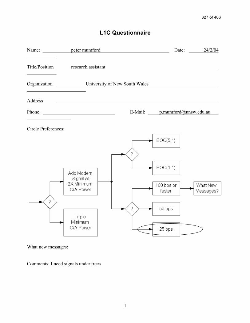
1
L1C Questionnaire
Name: peter mumford Date: 24/2/04
Title/Position research assistant
Organization University of New South Wales
Address
Phone: E-Mail: [email protected]
Circle Preferences:
What new messages:
Comments: I need signals under trees
327 of 406

2
Signature: peter mumford
For Attribution?: Your Name: Yes No Your Organization: Yes No
328 of 406

Intentionally Left Blankto Separate Responses
The Following is Reference # 50
329 of 406

1
L1C Questionnaire
Name: Chris Rizos Date: 12 February 2004
Title/Position Professor of Geodesy & Navigation
Organization School of Surveying & Spatial Information Systems
Address University of New South Wales, Sydney NSW 2052, Australia
Phone: +61-2-93854205 E-Mail: [email protected]
Circle Preferences:
What new messages:
Can’ t think of any at the moment! But we have years to think about this!
Comments:
I have placed fast messaging as my preference to help with fast TTFF. As a person interested in
surveying, and wants the gear to work in weak signal environments, I know this is not the optimal
choice. However I believe that we can use assisted-GPS to aid the receiver, so I’ m not concerned
about the possibility of not always being able to extract the data message under such (exceptional)
circumstances.
Signature: Chris Rizos
For Attribution?: Your Name: Yes No Your Organization: Yes No
330 of 406

2
Application Specific Questions
Name: Chris Rizos Date: 12 February 2004
Title/Position Professor of Geodesy & Navigation
Organization School of Surveying & Spatial Information Systems, UNSW
Your Primary Expertise
Professional& Scientific
Commercial Consumer
Land Y
Sea
Air
Space
Expected Number of Users in 2005
Professional& Scientific
Commercial Consumer
Land ?
Sea
Air
Space
Expected Number of Users in 2020
Professional& Scientific
Commercial Consumer
Land ?
Sea
Air
Space
Applications
1. Land surveying 2. Machine guidance/control3. Mobile mapping (land &
airborne)4. Geodesy 5. Deformation monitoring 6. High precision kinematic
positioning
Value
ParameterBest
DesiredWorst
Acceptable Importance
Accuracy <1cm 10cm 1
TTFF <10sec 2min 3
Availability 100% 90% 3
Continuity ?
Integrity ?
Robustness ?
Importance: 1 = Very, 3 = Moderate, 5 = Not Significant
331 of 406

Intentionally Left Blankto Separate Responses
The Following is Reference # 51
332 of 406

1
L1C Questionnaire
Names: Drs. G. Lachapelle, S. Skone, M.G. Petovello, and Mr. O. J ulien
Date: March 9, 2004
Organization Position Location and Navigation Group, Department of Geomatics Engineering,
The University of Calgary
Address 2500 University Drive NW, Calgary, AB, Canada, T2N 1N4
Phone: 403-220-5834 E-Mail: [email protected]
Circle Preferences:
What new messages:
Comments: See attached sheet
Signature:
For Attribution?: Your Name: Yes No Your Organization: Yes No
333 of 406

2
Application Specific Questions
Names: Drs. G. Lachapelle, S. Skone, M.G. Petovello, and Mr. O. J ulien
Date: March 9, 2004
Organization Department of Geomatics Engineering, The University of Calgary
Your Primary Expertise
Professional& Scientific
Commercial Consumer
Land X
Sea X
Air X
Space
Expected Number of Users in 2005
Professional& Scientific
Commercial Consumer
Land
Sea
Air
Space
Expected Number of Users in 2020
Professional& Scientific
Commercial Consumer
Land
Sea
Air
Space
Applications
1.
Value
ParameterBest
DesiredWorst
Acceptable Importance
Accuracy <1 cm 20 m 1
TTFF 0 s 30 s 3
Availability 100 % 100 % 1
Continuity Very High 3
Integrity Very High 3
Robustness Very High 3
Importance: 1 = Very, 3 = Moderate, 5 = Not Significant
334 of 406

3
Answer to the L1C Questionnaire
From Gérard Lachapelle, Susan Skone, Mark Petovello and Olivier J ulien, Department of
Geomatics Engineering, University of Calgary, Canada
The main fields of studies of the Department of Geomatics Engineering at the University of
Calgary related to GPS are (1) high accuracy positioning, (2) indoor or urban positioning and (3)
Use of GPS for atmospheric studies. Hereafter is a description of what would be expected from a
new GPS signal to improve the current performance of positioning and navigation in these two
areas. This description discusses only the signal itself and not the whole system.
For high accuracy positioning, there are two main sources of errors that limit the position accuracy:
multipath and atmospheric errors. To minimize multipath errors, a signal with low inherent
multipath-induced errors using a high chip rate and having a multipath-resistant correlation
function (essentially a narrow main peak) would be preferable. Atmospheric delay is the main
problem when medium to long baselines are considered. For this reason, atmospheric estimation
(that can include ionospheric first and second order delays as well as tropospheric bias) is
necessary. A strong signal power, reducing the impact of noise and the occurrence of cycle slips
would allow an easier and more robust atmospheric estimation process. The use of a signal
implementing these two propositions would provide a significant enhancement in the large numbers
of applications linked to high precision positioning such as RTK or meteorology.
For indoor and urban positioning, the main concern is the power loss when signals go through
materials. It often implies loss of lock, but also strong multipath environment as well as possible
cross-correlation problems. In order to improve navigation in such circumstances, a strong signal
with low cross-correlation peaks (long code) would be of tremendous benefit. Of course, a signal
with a high inherent resistance to multipath would be important as well. Finally, in order to have
more efficient acquisition and tracking in degraded environment, the presence of a data-less
channel is also needed to avoid squaring loss due to non-coherent integration.
For atmospheric studies, in particular for water vapour estimation, very precise broadcast orbits are
highly desirable. Thus a relatively high data rate for the navigation message would allow the more
frequent transmission of information which, with the proper structure, could lead to more precise
orbits. The latter would also improve single point positioning in real-time.
To summarize, although the idea of a very strong C/A code is seducing, the opportunity to have a
new signal that would better fit critical criteria such as the existence of a data-less channel or better
cross-correlation properties is more interesting. Moreover, the increase of the signal to noise ratio
through longer coherent integration decreases the problem of having a lower signal power. In order
to have more robust position solutions, the BOC(1,1) signal appears to have better characteristics
than the BOC(5,1) because of its more isolated and lower autocorrelation secondary peaks (relative
to the main peak), even if this implies a slightly higher multipath impact. It is however likely that in
the coming years, new techniques will reduce this impact of multipath to a smaller scale. A 50 Hz
data rate similar to the one currently used also seems appropriate.
335 of 406

Intentionally Left Blankto Separate Responses
The Following is Reference # 52
336 of 406

337 of 406

338 of 406

Intentionally Left Blankto Separate Responses
The Following is Reference # 53
339 of 406

1
L1C Questionnaire
Name: LT Parsons, Mr. Wolfe, Mr. Cleveland Date: 1/7/04
Title/Position: DGPS Project Engineering Staff
Organization: US Coast Guard Command and Control Engineering Center
Address 4000 Coast Guard Blvd, Portsmouth, VA 23435
Phone: (757) 686-4015 E-Mail: [email protected]
Circle Preferences:
What new messages: None
Comments: C2CEN would support a higher baud rate than 25 baud, if there were sufficient benefit
to justify it. For maritime applications, assuming that the receiver is tracking the legacy signal to
obtain clock and ephemeris data, it would be best if the 25 baud data stream on the BOC-1-1 signal
provided a means of enhancing user equipment integrity monitoring.
Signature: LT Parsons, Mr. Wolfe, Mr. Cleveland
For Attribution?: Your Name: Yes No Your Organization: Yes No
340 of 406

2
Application Specific Questions
Name: LT Parsons, Mr. Wolfe, Mr. Cleveland Date: 1/7/04
Title/Position DGPS Project Engineering Staff
Organization US Coast Guard Command and Control Engineering Center
Your Primary Expertise
Professional& Scientific
Commercial Consumer
Land X
Sea X
Air
Space
Expected Number of Users in 2005
Professional& Scientific
Commercial Consumer
Land Nationwide
Sea Nationwide
Air
Space
Expected Number of Users in 2020
Professional& Scientific
Commercial Consumer
Land Nationwide
Sea Nationwide
Air
Space
Applications
1. The US Coast Guard uses GPS to place and maintain aids to navigation.
2. The US Coast Guard uses GPS as a navigational tool aboard afloat platforms.
3. The US Coast Guard augments GPS with the N/DGPS system to provide users with better than 10 meter 2DRMS position accuracy and system integrity not inherent to GPS.
Value
ParameterBest
DesiredWorst
Acceptable Importance
Accuracy 10cm 30cm 1
TTFF 2min 15min 2
Availability 99.999% 99.9% 1
Continuity Not yet Defined Not yet Defined 3
Integrity Integral & Monitored Via Augmentation 1
Robustness <10events/1Mhrs <10events/1Mhrs 2
Importance: 1 = Very, 3 = Moderate, 5 = Not Significant
341 of 406

Intentionally Left Blankto Separate Responses
The Following is Reference # 54
342 of 406

1
L1C Questionnaire
Name: John Schutzenhofer Date: 1/13/04
Title/Position LT / Chief, DGPS Management Section
Organization USCG Navigation Center
Address 7323 Telegraph Rd. Alexandria, VA 22315
Phone: (703) 313-5939 E-Mail: [email protected]
Circle Preferences:
What new messages:
Comments:
I chose 25 bps over 50 bps since I feel it is more important to be able to acquire a message in poor signal
conditions than having a faster TTFF.
Signature: John Schutzenhofer
For Attribution?: Your Name: Yes Your Organization: Yes
343 of 406

2
Application Specific Questions
Name: John Schutzenhofer Date: 1/13/04
Title/Position LT / Chief, DGPS Management Section
Organization USCG Navigation Center
Your Primary Expertise
Professional& Scientific
Commercial Consumer
Land
Sea X
Air
Space
Expected Number of Users in 2005
Professional& Scientific
Commercial Consumer
Land
Sea
Air
Space
Expected Number of Users in 2020
Professional& Scientific
Commercial Consumer
Land
Sea
Air
Space
Applications
1. The Coast Guard uses GPS (DGPS) to accurately place Aids to Navigation.
2. The Coast Guard used GPS in the development of the differential correction signal (DGPS).
Value
ParameterBest
DesiredWorst
Acceptable Importance
Accuracy 10 cm 3 m 3
TTFF 1 min 15 min 5
Availability 99.999% 99.7% 1
Continuity
Integrity Alarm <5 sec Alarm >10 sec 3
Robustness 1
Importance: 1 = Very, 3 = Moderate, 5 = Not Significant
344 of 406

Intentionally Left Blankto Separate Responses
The Following is Reference # 55
345 of 406
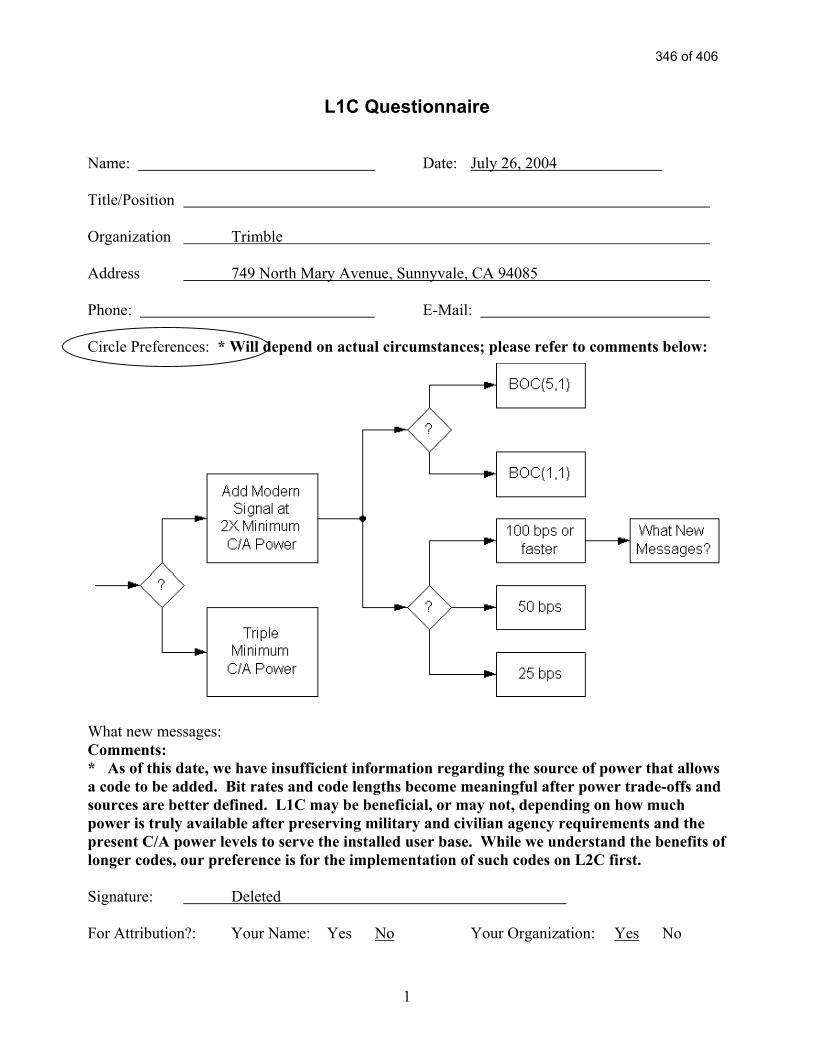
1
L1C Questionnaire Name: Date: July 26, 2004 Title/Position Organization Trimble Address 749 North Mary Avenue, Sunnyvale, CA 94085 Phone: E-Mail: Circle Preferences: * Will depend on actual circumstances; please refer to comments below:
What new messages: Comments: * As of this date, we have insufficient information regarding the source of power that allows a code to be added. Bit rates and code lengths become meaningful after power trade-offs and sources are better defined. L1C may be beneficial, or may not, depending on how much power is truly available after preserving military and civilian agency requirements and the present C/A power levels to serve the installed user base. While we understand the benefits of longer codes, our preference is for the implementation of such codes on L2C first. Signature: Deleted For Attribution?: Your Name: Yes No Your Organization: Yes No
346 of 406

CIVIL USER GROUP BENEFITS
The following attachment presents the benefits of the 4th civil signal, L1C. The first section, (A)Benefits, will provide the reader with a short understanding of each of the six categories that thispaper considers as the benefits of L1C. Section (B), Benefits Matrix, is a quick reference guide(first seen on page XX) that enables the reader to easily associate the benefits described withthose portions of the GPS civil user community (studied for this paper) that can reap the greatestreward from L1C’s introduction. Section (C), Benefits Explained, will show in great detail theunderstanding of how each studied user group us currently uses GPS and how the 4th civil signalwill enhance that particular groups productivity and effectiveness in the future. Specificexamples (that explain each “X” in the Matrix) are also provided in each user group’s section.Finally, section (D) Team Member POCs, provides a list of the personnel responsible forresearch on each user group.
A347 of 406

Section A: Benefits
L1C Improvement User Benefit Explanation
Lower Signal Thresholds forNavigation
(Power & Dataless Channel)
The user will be more likely to navigate(a) in difficult signal conditions, such
as in a forest, in a city, inside abuilding, on a tree lined road, etc., i.e.,where GPS signals are attenuated, as
well as (b) in the presence of radiofrequency interference (RFI) to GPS.
A stronger signal and the datalesschannel allow the receiver to track and
make navigation measurements in morechallenged signal conditions than now.
The improvement is at least 6 dB.
More Robust AutonomousNavigation
(Power, Forward Error Correction(FEC), & Data Rate)
The user will be more likely to obtainthe satellite messages needed to
begin navigation (a) in difficult signalconditions, such as in a forest, in a
city, inside a building, on a tree linedroad, etc., i.e., where GPS signals are
attenuated, as well as (b) in thepresence of RFI to GPS.
The “time to first fix” (TTFF) after theGPS receiver is turned on depends on
receiving an “ephemeris” messagefrom each available satellite.
As a result, the user will get a fasterTTFF.
A stronger signal and FEC will permitmessage recovery with weaker signals
or with more radio frequency noise. Theimprovement is 5 dB at 50 bps and 8 dB
at 25 bps. The 8 dB improvementmakes it possible to obtain messageseven with the weakest GPS signal the
receiver can track.
Note that once the ephemeris messageis received, it lasts for one to threehours, so continuous reception of
messages is not required, but time tofirst fix depends on receiving messagesquickly after the receiver is turned on.
This benefit relates to “autonomous”navigation, meaning that ephemeris
messages are received from thesatellites and not provided by a network,
as is often done for E-911 use.
348 of 406

L1C Improvement User Benefit Explanation
Less Susceptible to Interference(Power & Code Structure)
The user will be more likely to navigatein the presence of RFI to GPS.
Interference protection is part of theimprovements noted above (highersignal power, the dataless channel,
FEC, and a lower data rate). However, itis repeated here to point out that
although code structure does not helpwith weaker signals, it does help in theface of certain types of RF interference.(It does not help against Ultrawide Band
(UWB) interference.)
Higher Dynamics Tracking(Power and Dataless Channel)
Precise measurements will be moredependable in physically difficult
situations, such as GPS guidance ofan earthmover blade as it hits rocksand concrete – transmitting intense
shock and vibration to the GPSantenna.
Some of the most demanding accuracyrequirements are in severe physical
conditions, such as GPS guidance ofconstruction and earthmoving
machinery. These environments aresubject to high levels of shock andvibration (jerk and acceleration). A
stronger signal and a dataless channelpermit the tracking loop to remain lockedwith 64 times higher levels of jerk and 16times higher levels of acceleration at the
antenna.
Reduced Cross-correlation(Longer Spreading Codes)
Reduces the possibility of tracking anincorrect satellite without needing
verification algorithms in the receiver.Improves performance in challengedenvironments when there are weak
and strong signals visible.
Using long codes will reduce cross-correlation between satellites signals,
reduce the self-interference experiencedby C/A code, and increase the amount
of dynamic range possible betweensatellites.
Improved Accuracy (Increasedsignal bandwidth)
More accurate position locations arepossible in the same challenged
environments.
All of the modulations underconsideration have at least 3 dB more
bandwidth than C/A code. This willimprove accuracy for the same level of
receiver complexity, and is primarilybeneficial for lower cost receivers.
349 of 406

Section B: Benefits Matrix
L1C Improvement ⇒
Application⇓
Lower SignalThresholds for
Navigation (Power& DatalessChannel)
More RobustAutonomousNavigation
(Power, FEC &Data Rate)
Less Susceptibleto Interference(Power & Code
Structure)
HigherDynamicsTracking
(Power andDatalessChannel)
ReducedCross-
correlation(Longer
SpreadingCodes)
ImprovedAccuracy(Increased
signalbandwidth)
Location BasedServices/Recreation
X X X X X
Scientific X X X
Aviation X X
Agriculture X X X X
Surface Transportation X X X X X
Mining & Construction X X X X X
Surveying/Civil Engineering X X X X
Public Safety/Security X X X X X
Timing X X
Rail X X X X
Space X X
Environment X X X
Maritime and Waterways X X X X
Note: The last column “Improved Accuracy (Increased signal bandwidth)” greatly depends on the particular receiver used in each instance. Whileimproved accuracy is an added benefit of L1C in roughly half of the studied cases, it is largely dependent on the combination of the improved signaland improved receivers.
350 of 406

SECTION C: Benefits Explained
L1C ModernizationCivil Outreach Program
LOCATION BASED SERVICES/RECREATION
• APPLICATIONS
• Personal Productivity - Increased time efficiencies - Ease of use - Portability - Flexibility/Utility
• Resource/Management- Asset tracking/monitoring- Situational Awareness- Personal security- Location determination
• REQUIREMENTS• Accuracy: 1 meter or less• Availability/Coverage: Challenged Environments/Inside• Power Consumption• Jamming/Interference• Timing: 10 nanoseconds
References
Location-based services information was obtained from literature reviews, interviews,discussions with manufacturers and data obtained from documents submitted in support of theGPS-III program.
Location-based services can be viewed as a non-critical navigation and position determinationcategory pertaining to the personal/individual use of low cost GPS receivers for a broad range ofapplications. Consequently, the number of users will likely be the largest of all the categoriesunder consideration particularly when GPS navigation and position determination capabilities arecombined with a communications capability in a low cost/affordable, and practicalreceiver/transmitter.
Hand-held GPS devices, coupled with data base flexibility and communications capabilities, willlikely be as prevalent in the future, as cell phones are today. Users will want these hand helddevices to be smaller and inexpensive, longer-lasting and flexible.
351 of 406

As with the cell phone, use of future GPS equipment will not be tied to a specific platformapplication such as personal automobile navigation, rather, consumers will want to use a singledevice for multiple applications. For instance: recreation (e.g. boating, hiking, sightseeing);avoiding being lost (either outside or inside a building) tracking and/or monitoring resources(employees, vehicles, pets and family members) and emergency assistance (such as the currentE911 initiative).
The goals of the user will likely be focused on improving personal productivity by better timemanagement and reducing “down” time, managing and/or tracking resources, and situationalawareness.
To achieve these goals, the user will want GPS to be available everywhere—inside buildings, inurban canyons, parking garages, remote locations and challenged, high jamming/interferenceenvironments, etc. In addition, there will be a desire to use the receiver continuously resulting inpower consumption becoming increasingly critical, as will the size and functionality of thedisplay, ease of use (user friendliness), data base flexibility and completeness, operationalreliability, and overall cost—both initial purchase and user charges.
One vision of a fully functional personal unit satisfying these user requirements is a low-costwrist watch sized unit, similar to today’s digital watch but with a magnified display, capable ofremotely downloading a required data base on an as-needed basis.
The envisioned unit will be fully programmable (i.e. voice/command entry) to satisfy multiplefunctions (e.g. navigation. resource tracking etc.) The initial cost of the wrist watch unit willlikely be nominal, but will require a guaranteed subscription contract for data base andcommunications services for a minimum number of months/years.
Regardless, whether the individual unit be a wrist watch device or some other configuration, themotivation for purchasing the equipment will likely be driven by a desire to increase personalproductivity, manage resources and assure reliable situational awareness. User equipmentflexibility and subsequent personal utility will be the key factors in the decision to buy.Investment in GPS-based equipment for personal use will likely be evaluated on an individuallevel based on the cost of the unit, user equipment flexibility, immediate personal utility (solvingan immediate problem/concern), potential/future productivity improvements, and quality of lifebenefits associated with owning one or more units.
Data base availability and two-way data link (other enabling technologies) will likely dominatethe growth curve for development and sales of mobile personal units. Miniaturization, displayadvancements and power-cell improvements will be important, but they are not critical path“utility” enablers.
Utility will be optimized by having accurate, functionally supportive data readily available, on-demand, as conditions dictate. Preprogramming of a personal unit, advanced knowledge of allthe information required and sufficient personal unit storage capability will likely not be possiblein one unit. Hence the need for data link and on-demand database services.
352 of 406

Examples (Note: reference numbers (e.g. (1,1)… (3,5)…) correspond to the Xs in SectionB: Benefits Matrix)
(1,1) A stronger signal and data-less channel thereby improving the ability to rely on GPSservices in challenged environments, such as under forest cover, beside tree-lined roads, in urbancanyons and inside buildings (e.g., 911 applications).
(1,1) A stronger signal and data-less channel thereby expanding recreational uses in challengedenvironments, such as forested areas.
(1,2) Improved signal acquisition and tracking thereby expanding the utility of GPS forestablishing position location and monitoring movements in regions where the satellite signalsare weakest, such as high-rise buildings and city environments.
(1,2) Improved signal acquisition and tracking thereby increasing the utility of GPS to determinean initial position location and reducing the probability of loss of signal enabling continuousnavigation without disruption. Potential applications include improving the ability tofind/relocate trails, campsites, water accesses, wells, fishing locations, etc.
(1,3) Greater resistance to radio frequency interference (both intentional and unintentional)thereby increasing the reliability of GPS receivers for determining and maintaining positioninformation in locations susceptible to such radio interference.
(1,5) Longer spreading codes and reduced cross-correlation between satellite signals (i.e. selfinterference) thereby improving receiver performance in challenged environments where bothweak and strong satellite signals are available, such as inside buildings or under forest cover.
(1,6) Improved accuracy and position determination capability due to increased signalbandwidth thereby improving the location accuracy and identification of objects (e.g. firehydrants; water/gas meters, control valves utility poles, etc.) and people in challengingenvironments.
(1,6) Improved accuracy and position determination capability due to increased signalbandwidth thereby improving overall receiver utility (e.g. finding/relocating trails, campsites,water accesses, wells, fishing locations/nets, etc.).
353 of 406

L1C ModernizationCivil Outreach Program
SCIENTIFIC
• APPLICATIONS
• Resource Management - Manpower reduction - Time efficiency - Equipment placement
- Off-site preparation
• Improved Geodetic Database - Frequency of updates - Densification of network - Unification of Datum
• REQUIREMENTS
• Accuracy• Timing• Availability/Coverage
References
Scientific information was obtained from literature reviews, interviews, discussions withmanufacturers and data extracted from documents submitted in support of the GPS-III program.
Scientific uses of GPS span a broad range of applications; from space, atmospheric, oceanic, andearth research to the tracking and monitoring of migratory herds.
Some of the most demanding scientific requirements are found in the Geodetic Surveycommunity. Geodetic survey is a vital element for Geodesy. In turn, Geodesy is at the heart ofmany scientific applications because it is the science that specializes in determining the shapeand size of the Earth and its gravity field in three-dimensional space and time.
These three dimensional position coordinates and precise time on a unique terrestrial referenceframe are directly derived by using GPS services. Use of this information can be essential fororienting space/satellite sensor data to the location of points on the earth for: communicationsystems, weather systems, GIS systems that identify topography, land use, and ocean conditions.
354 of 406

Over the years GPS based methodologies have set the record in achieving highest positionaccuracy in near real-time by complementing creative observational methods, ground/spaceaugmentation and innovative data processing techniques. Geodetic surveyors would like a simplelow-cost, low-power, light-weight GPS receiver which can deliver 1 cm accuracy in real timeany where in the world at all times.
The improved accuracy, integrity and availability of service are important for variousgeophysical measurements. In many instances these measurements are taken in “challengedenvironments” and reliable signal availability can be a problem. For instance: data collected toentrap geophysical activity across the plate boundaries or in an earthquake zone are of greatimportance to forecast crustal movements.
The precise position coordinates and time on a unified global reference frame would provide aseamlessly interoperable global system with no loss of accuracy and integrity to the geodesists,geophysicists and navigators. The future vision of geodetic survey is to be able to complete asurvey project (which used to take days to weeks) almost in real time with 1000 times moreaccuracy. It is believed that worldwide capability of real time accurate 3D positioning (1 cm) atany given time is going to make the greatest impact on “our collective economic development.”
Improved real-time and post-processing algorithms are going to provide the power to extractevery bit of the possible accuracy from the measurements. Precise satellite calibration andsatellite body modeling are going to aid precise orbit determination, thereby improving theposition and timing accuracy.
Clearly GPS signal performance—in terms of reliability and availability—are a definite must forthe geodetic community. Reliability and availability are also critical for other scientificapplications, particularly those that involve tracking and monitoring the movement of objects.For instance: migratory herds, natural and manmade objects (e.g., ice flows, oil spills, buildings,bridges, etc.), precise placement of equipment for “building” data collection networks—sensors,monitors, etc.
Examples (Note: reference numbers (e.g. (1,1)… (3,5)…) correspond to the Xs in SectionB: Benefits Matrix)
(2,1) A stronger signal and data-less channel thereby improving positioning support forgeological mapping, tracking migratory wildlife, etc. in presence of foliage. Could expand thelarge range of uses of GPS services for recording the movements of tectonic plates, anddocumenting volcanic, earthquake and landslide activity.
(2,3) Greater resistance to radio frequency interference (both intentional and unintentional)thereby increasing the reliability of GPS services in places subject to such radio interference.
(2,5) Longer spreading codes and reduced cross-correlation between satellite signals (i.e., self-interference) thereby improving receiver performance in challenged environments where weakand strong satellite signals are available, such as areas with dense surrounding vegetation.
355 of 406

L1C ModernizationCivil Outreach Program
AVIATION
• APPLICATIONS
• Airspace System Efficiencies - Increased Capacity/Access - Reduced Separation - Lower Emissions/Noise - Safety Enhancement
• Operational Improvements - Optimized Scheduling - Delay Reduction - Fuel Savings - Situational Awareness
• REQUIREMENTS (Application Dependent)
• Accuracy• Integrity• Continuity of Service• Availability/Coverage
References
Aviation services information was obtained from, literature reviews, interviews, discussions withmanufacturers and data obtained from documents submitted in support of the GPS-III program.
The current GPS civil signals do not provide adequate levels of integrity, availability, andcontinuity of service to permit GPS to replace ground-based navigation aids for manned safety-of-life applications.
Augmentation systems such as the wide area augmentation system (WAAS) and local areaaugmentation system (LAAS) are being developed to address some aspects of current GPS civilsignal services, but there are many aspects of the current GPS that make it difficult to achieverequired performance levels, even with augmentations.
There are a number of key, underlying assumptions being made by the civil aviation communityin its use of GPS for high integrity applications and in the deployment of augmentations that maynot be widely recognized. Future GPS signal improvements need to consider these civil
356 of 406

assumptions to preserve the investments being made for augmentation systems and GPSequipment. These include:
• Single Satellite Fault Assumption. A key assumption made in the use of receiverautonomous integrity monitoring (RAIM) fault detection error (FDE) algorithmsin the civil airspace is that probability of multiple satellite failures is so small thatit can be ignored.
Proposed operational changes to provide navigation data uploads simultaneouslyto all satellites creates the risk of multiple satellite failures, since an incorrectephemeris/clock load could be propagated to all satellites at once. Even ifmonitoring could catch this quickly, this still presents a problem for overallconstellation availability and continuity.
• Signal Quality Monitoring Assumptions (SQM). Due to lack of detailedknowledge of satellite signal fault modes, the civil community has had to makeassumptions about the form and magnitude of signal anomalies. Thus, there arelimited assurances that current SQM designs will catch the most likely civil signaldistortions. Consequently, there is some risk that the investments being made inWAAS and LAAS ground equipment will not yield target levels of safety.
Other improvements that are desired by the aviation community include service guarantees in thefollowing areas:
• Reduction in satellite failure rate and improvement in constellation monitoringcould remove the need to do fault detection and exclusion.
• Increased numbers of satellites and more robust civil signals for improvedcoverage, availability and continuity, particularly in challenged environments.
• Increased guaranteed minimum signal power to improve interference margins.
• Velocity performance guarantees for GPS heads up display guidance, inertialalignment, and paired operations.
From a signal design perspective, ranging precision including multipath effects is not a dominanterror component for en route through precision approach (APV or LPV) using GPS/WAAS, butis a significant error source for LAAS Category II-III precision approaches (particularly whenthe provision of integrity is considered). For present-day WAAS, residual ionospheric errors aredominant. If, as planned, WAAS users migrate to using L1 and L5 for direct ionosphericmeasurements, then ranging precision may become a more significant factor. Improving rangingprecision over that provided by the C/A-code may also be important if GPS III is to provideintegrity from GPS without augmentation.
Examples (Note: reference numbers (e.g. (1,1)… (3,5)…) correspond to the Xs in SectionB: Benefits Matrix)
357 of 406

(3,3) Greater resistance to radio frequency interference (both intentional and unintentional)thereby improving the overall navigation performance and reliability for both manned andunmanned aircraft/vehicles.
(3,5) Longer spreading codes and reduced cross-correlation between satellite signals (i.e. selfinterference) and a data message which identifies the satellite, thereby improving receiverperformance, especially in challenging operational conditions where weak and strong satellitesignals are available.
358 of 406

L1C ModernizationCivil Outreach Program
AGRICULTURE
• APPLICATIONS
• Yield mapping• Soil Sampling, Soil Preparation• Irrigation• Precise, Real Time Surveying• Vehicle/equipment control• Harvesting/Product tracking• Government subsidizes/incentives
• REQUIREMENTS
• Accuracy: one meter or less• Availability: 99.9% or better• Integrity: 5 seconds or better• Repeatability
References
Agriculture information was obtained during interviews with US Department of Agriculture(USDA) representatives; discussions with equipment manufacturers, literature reviews and dataobtained from documents submitted in support of the GPS-III program.
Yield Mapping
GPS use has the potential of providing site-specific optimization of land use—Yield Mapping.Yield Mapping is a process of determining exactly what is needed to increase crop productionwhile reducing environmental impacts. Fertilizer application and insecticides/pesticides areprimary concerns. Nitrogen use/application is a dominant issue and application of nitrogenneeds to be site specific. One meter level accuracy or better is required and repeatability iscritical. Repeatability is the ability to return to the exact same spot at different times throughoutthe year.
Yield Mapping, made possible by improved GPS performance, is not a sole function of GPS. Itrelies on a total system/process properly integrated to achieve the desired result. Specifically,those systems/processes include a mechanism for accurate soil sampling, the application medium(e.g. farm equipment), and precise control of the application.
359 of 406

Soil Sampling/Soil Preparation
Soil sampling, or mapping of the soil, requires sub-meter accuracy to determine the variations ofsoil content and composition. Variations of soil content and composition will establish abaseline for initial soil preparation and soil maintenance. Currently, differential GPSaugmentations are available to achieve these accuracy levels. However, they are not inwidespread use and are relatively expensive.
Irrigation
Irrigation is another agricultural necessity that will benefit from GPS. Several mechanizedsystems are used to irrigate fields, such as large rotating arms with multiple rotating sprinklerheads and fixed irrigation pipe with rotating sprinklers. Precise irrigation will both increase peracre yield and reduce the amount of water used to achieve crop optimization. Increased,repeatable GPS accuracy will be needed to achieve improved irrigation, less than 10 meters, bothhorizontal and vertical.
Precise, Real Time Surveying
Real-time, precise surveys, (centimeter level accuracy) such as the ones needed for irrigation,could provide significant economic benefit to the farmer as well as improve environmentalconditions. An example of the benefits of real-time, precise surveys coupled with precise vehiclecontrol is as follows:
Harvesting/Product Tracking
Accurate, repeatable planting, cultivation, insecticides/pesticides applications, and harvesting areessential for per acre product optimization. In preparation for planting, farmers fertilize in theFall. When it is time to plant, they attempt to plant exactly where they fertilized, but this isobviously difficult to do. As a result, planting may not occur at the optimum fertilized location.To ensure this does not occur, farmers generally apply large amounts of fertilizer, both costly tothem and harmful to the environment (nitrogen). Cultivation requires sub-centimeter accuracy.A large machine moving between rows of crops must remain properly oriented and controlled,otherwise crop destruction will occur. The same conditions apply for harvesting. In addition, atwenty-four hour harvesting capability would theoretically double the value of a harvestingmachine and cut harvesting time by 50%. Centimeter level control would be needed, as well ashigh system availability/integrity (99.9%+/5 seconds or better), with an automatic equipmentshutdown feature in the event of a signal failure or loss.
Recording of product. As we move more towards genetically engineered crops, there will be aneed to trace the history of the end state product. For instance, aerial application of chemicalsmust be precisely known (e.g. path flown, type of chemical, etc.), methods used to engineercrops—this information will likely be needed for the Federal regulators, the people purchasingthe crop (Note: today’s regulations to qualify for an organically grown product), and the endstate consumer. Preservation of crop identity (Pharming) from soil preparation to thesupermarket will benefit from improved GPS and affordable equipment.
360 of 406

Vehicle/Equipment Control
Farm size and efficiencies are another area that could benefit from better GPS performance. Toremain in the farming business, farmers have had to expand. For example, the price of a bushelof wheat has not significantly increased in the past two decades, but the cost to produce thatbushel of wheat has gone up dramatically. To stay in business, the farmer has to produce morebushels of wheat. Small farms have gone by the wayside and farms are generally getting larger.Big farms require either more or bigger equipment to work the fields. Equipment has beengetting bigger to accommodate this need. Main reason is productivity. One person operating alarge machine can produce more than one person operating a small machine. But machine sizeand related expenses are not linear, in terms of both initial purchase price and cost ofoperations/maintenance. A machine capable of twice the output may cost ten times the price.Several small machines may be economically attractive, but their practical use in today’s world,is not viable. However, if an improved GPS-L1C, with reliable, sub-meter performance could beused to automatically control a fleet of small machines, day or night, the move to biggermachines may end. Integrity will be an important enabler of fleet farming—as a guide: 5seconds or better.
Government Subsidizes/Incentives
Farming is generally not a business. Survival is the key, keeping everything running from year-to-year. The Farm Bill is a major factor. This Bill keeps farmers alive, and it is taken veryseriously. If the Farm Bill levies a requirement to do something—like use a GPS basedsystem—to qualify for a subsidy, use of the GPS based system will likely occur.
The Environmental Protection Agency (EPA) is an extremely powerful motivator. Currently,nitrogen and pesticides are big issues in the EPA. If the EPA issued a regulation or gave afarmer relief from a regulation if a GPS-based system were used, then the GPS-based systemwould likely be used as soon as possible.
Examples (Note: reference numbers (e.g. (1,1)… (3,5)…) correspond to the Xs in SectionB: Benefits Matrix)
(4,1) A stronger signal and data-less channel thereby increasing the utility of relying on GPSservices in orchards and under tree canopies to enable an accurate assessment of crop conditionsand more reliable control of both field/soil maintenance and harvesting equipment.
(4,2) Improved signal acquisition and tracking thereby improving the ability to determine site-specific optimization of land production in places where satellite signals are weakest, e.g., undera tree canopy. Optimization of land production includes yield mapping—determining exactlywhat is required for improved crop production (e.g. insecticides, pesticides, fertilizers).
(4,4) Higher dynamics tracking of GPS signals enabling the ability to retain signal lock with 64times higher levels of “jerk” and 16 times higher levels of antenna acceleration thereby
361 of 406

improving the performance of earthmoving and land preparation machinery subject to strongshock and vibration.
(4,5) Longer spreading codes and reduced cross-correlation between satellite signals (i.e. selfinterference) thereby improving receiver performance in challenged environments where weakand strong satellite signals are available, such as in orchards/tree farms.
362 of 406

L1C ModernizationCivil Outreach Program
SURFACE TRANSPORTATION
• APPLICATIONS• Command and Control• Optimized Scheduling• Lower operating costs• Asset/Resource Tracking• Reduced Congestion• Fuel Savings• Lower Emissions• Increased road capacities• Increased Operator efficiencies/safety• Accident investigation• Collision avoidance
• REQUIREMENTS• Accuracy: 10 cm• Integrity: 10 seconds or less• Availability/Coverage: 99.9%• Fix Interval: 1-2 seconds
References
Surface Transportation information was obtained during discussions with Federal HighwaysAdministration (FHWA) personnel, literature reviews, discussions with equipmentmanufacturers, and data obtained from documents submitted in support of the GPS-III program.
The following summary of highway statistics and scenarios provide a relative framework forassessing the potential benefits of using GPS-based systems and services in the vehiculartransportation area:
More than 6,000,000 accidents happen on US highways every year, resulting in more than5,200,000 injuries and more than 41,000 fatalities every year.
The total cost of these mishaps are in excess of $150 Billion per year. It has been estimated thatas much as three-quarters of these accidents could be prevented if the driver's attention were notdiverted in the moments before the collision. The National Highway Safety Administrationestimates that 1.1 million (17%) of all crashes could be prevented if all vehicles had threedevices installed, (1) rear end notification, (2) roadway departure and (3) lane/change mergewarning.
363 of 406

GPS is an enabling technology for these devices. The estimated benefit of these devices wouldbe the saving of thousands of lives and at least $23 Billion per year.
An Automatic Collision notification device (like the Cadillac On-Star System) that sends out asignal giving time, location and notice that an air bag has deployed would help dispatchemergency services with reduced arrival times, which saves lives. Forty percent of all traveledmiles are on rural roads, but they account for 60% of all traffic fatalities because of slowemergency response, greater distances, and lack of precise accident location information in realtime. GPS use can provide precise accident location information regardless of the location,assuming adequate coverage and availability of signal services.
The use of GPS based technologies to exercise positive control and management of manned andunmanned fleet operations as well as real time asset and resource tracking is a growing business.Current uses include tracking and monitoring of platforms in real-time; logging/recordingvehicle location and issuing status/progress reports; initiating and/or commanding actions basedupon platform status, such as dispatching maintenance crews, changing delivery schedules,rerouting vehicle, and providing real time notification to end state users.
Use of GPS to further improve Fleet Management operations and provide bottom line dollarbenefits are expected to continue to expand based upon the availability and performance levels ofGPS services. Signal availability and coverage are critical path items for Fleet Managementgrowth, followed closely by user equipment cost and size. Coverage in the city canyons isneeded with availability at 99.9% or higher.
Fleet Management operations for companies that have drivers out in the field benefit by usingGPS coupled with communication capabilities. Typical users include electrical, plumbing,telecommunications, couriers, etc. A dispatcher collects vehicle data, such as maximum speed,vehicle location, length of time at specific location, and activation of specific events associatedwith vehicle operations. The information is then used to measure vehicle and driverproductivity. Management reports provide data in a variety of formats, including number ofstops, average stop length, and percentage of total time spent on service calls.
GPS supported Traffic/Highway Movement improvements are beginning to enter the inventoryand growth is anticipated in the following areas:
• Intersection collision avoidance. GPS is being considered as one potential sensor (alongwith onboard radars and road sensors) for this application.
• Automatic Vehicle Location (AVL) – This is a general category of systems that are
geared at determining vehicle position for fleet tracking, etc. Public safety users (e.g.,police cars, fire trucks) are leveraging research funded by the Department of Justice(DOJ) for Federal vehicle tracking. In larger metropolitan regions of the U.S. most busesare equipped with GPS for AVL. This is occurring mostly for driver/passengerprotection. An example was cited of a hijacked bus being quickly recovered because ofGPS-based AVL. Bus AVL equipage is growing, even in suburban/rural areas.
364 of 406

• Road construction/grading, surveys of roadside infrastructure – similar to most surveyingapplications, cm-level accuracy is required. Better surveying results in longer road-life.Caterpillar has been very involved in applying GPS technology in road constructionequipment.
• Road quality monitoring – Some vehicles are equipped with photographic equipment todetect road surface faults (cracks, potholes). GPS is used to locate the faults so that roadcrews can be sent for repairs. The accuracy required from GPS for these photo-loggingsystems is on the order of 1 m, 2-sigma.
• Traffic monitoring – several studies have placed GPS receivers on a number of privatecitizen automobiles in order to better understand typical driving habits. These studieshave concluded that questionnaires to determine driving habits are not very accurate – itwas found that in the questionnaires most respondents left out many trips
• Intelligent Transportation Systems (ITS): ITS involves the use of technology to improvehighway efficiency/safety. Cameras and magnetic loop sensors embedded in roadsprovide situational awareness to traffic operation centers (TOCs). Employees at theTOCs monitor traffic and post alerts as necessary on roadside variable message signs.Traffic information is also provided to the public via websites. Atlanta has perhaps themost sophisticated TOC, which was compared in appearance to something from “StarTrek.” One current trend is to increase the level of communication among various TOCs,so that travelers have advance notice of traffic at far-away destinations.
• Autonomous vehicle operations are a driver for both accuracy and integrity performance.An accuracy of 10 cm, to maintain lane orientation and a 10 second integrity threshold orbetter has been suggested as a performance requirement.
Examples (Note: reference numbers (e.g. (1,1)… (3,5)…) correspond to the Xs in SectionB: Benefits Matrix)
(5,1) A stronger signal and data-less channel thereby improving the ability to continuouslynavigate in challenged environments, such as beside tree-lined roads and in urban canyons.
(5,2) Improved signal acquisition and tracking thereby increasing the utility of GPS to determinean initial position location and reducing the probability of loss of signal enabling continuousnavigation without disruption.
(5,3) Greater resistance to radio frequency interference (both intentional and unintentional)thereby improving the efficiency and effectiveness of resource/asset monitoring, dispatch andcontrol—such as fleet operations.
(5,5) Longer spreading codes and reduced cross-correlation between satellite signals (i.e. selfinterference) thereby improving receiver performance in challenged environments where bothweak and strong satellite signals are available, such as in cities and along tree lined roads.
365 of 406

(5,6) Improved accuracy and position determination capability due to increased signalbandwidth thereby improving the efficiency and effectiveness of resource/asset monitoring,dispatch and control—such as fleet operations.
366 of 406

L1C ModernizationCivil Outreach Program
MINING/CONSTRUCTION
• APPLICATIONS• Centralized Precision Command and Control of Equipment• Remote Operations• Lower operating costs• Asset/Resource Tracking• Survey/Assessment• Material Placement• Resource/Equip Location• Personnel Assignments
• REQUIREMENTS• Accuracy: 5-10 cm• Integrity: unspecified• Availability: continuous (open pit mine, construction site mask angle
problems)
References
Mining/Construction information was obtained during discussions with equipmentmanufacturers, literature reviews and data obtained from documents submitted in support of theGPS-III program.
Mining and Construction activities are site specific operations. Consequently, the utility of GPSis a function of site characteristics, localized conditions and the subsequent availability of GPSsignals at the site location.
An initial requirement is to build, using GPS survey equipment, a precise GeographicalInformation System (GIS). For instance, mining operations depend upon a GIS reference database for information such as:
• Physical characteristics (Height, Spatial Location, etc.)• Micro Soil / Rock / Mineral Types• Record of Previous Excavations
Mining equipment, and to a certain extent construction equipment, can be autonomouslycontrolled through an integration of the GIS reference data base, equipment specific positioninformation and the desired task to be performed. Advanced computer vision applications canalso be applied thereby reducing and, in some instances, deleting the need for manual/labor-
367 of 406

intensive physical equipment operation. In particular, surface mining equipment may be outfittedto perform in this fashion.
Planning and resource management of mining operations are commonly governed by a resourceplanning system that uses the GIS reference data base as one of its main inputs for performingmining decision analyses. The decision analyses function of the resource planning systemdetermines the optimum use of available resources for completing specific tasks. In turn, a taskplan is developed, a schedule is produced, specific equipments functions are determined, etc. andthis information is provided to the decision maker(s) for execution.
Following equipment programming, the equipment autonomously navigates the entire areaperforming the activities in accordance with the plan. Typical activities include scraping,excavating/digging, leveling, loading of ore/surface debris into trucks for transport, reporting ofon-board sensors on the condition of the soil/minerals and plants (if any) by time and location forfuture evaluation/analysis, etc.
This typical scenario ends successfully when the task plan has been completed and all gatheredinformation has been provided to the resource planning system and/or the GIS reference databasehas been updated--as appropriate. The scenario ends unsuccessfully if the equipment is unable tocomplete the plan (e.g. due to an obstacle not in the plan, equipment failure, loss of position data,etc).
Specific benefits of evolving to this type of GPS based system for mining and constructionoperations include:
• Increased Automation of Mines/Construction Sites. Fewer required human heavy equipmentoperators onboard the actual equipment.
• Increased Safety. It may be the case that mining and construction operations can take placein areas where it may be too dangerous to send human operated equipment.
• Environment Mitigation. In many areas land reclamation is required after the miningoperations cease. Tracking of large topographic features can minimize and automate thereclamation effort
• Size and Cost of Mining/Construction Equipment. It is believed that the unit size of a pieceof mining equipment may become smaller, as it is believed equipment size has been driven tomaximize operator efficiency and productivity. Typically the cost of a larger version of apiece of equipment is substantially greater than the cost of a smaller variant.
Examples (Note: reference numbers (e.g. (1,1)… (3,5)…) correspond to the Xs in SectionB: Benefits Matrix)
(6,1) A stronger signal and data-less channel thereby improving the ability to continuouslynavigate and operate machinery in challenged environments, such as open pit mines or underfoliage.
368 of 406

(6,2) Improved signal acquisition and tracking thereby increasing the utility of GPS to determinean initial position location and reducing the probability of loss of signal enabling continuousnavigation without disruption.
(6,3) Greater resistance to radio frequency interference (both intentional and unintentional)thereby improving the performance of GPS receivers in locations subject to such radiointerference.
(6,4) Higher dynamics tracking of GPS signals enabling the ability to retain signal lock with 64times higher levels of “jerk” and 16 times higher levels of antenna acceleration therebyimproving the performance and guidance of earthmoving and construction equipment (e.g.graders, loaders, shovels, trucks, etc.).
(6,5) Longer spreading codes and reduced cross-correlation between satellite signals (i.e., selfinterference) thereby improving receiver performance in challenged environments where bothweak and strong satellite signals are available.
369 of 406

L1C ModernizationCivil Outreach Program
SURVEYING/CIVIL ENGINEERING
• APPLICATIONS• Static and Dynamic Survey• Movement/Motion Detection• Site Preparation• Material/Equipment Location-Placement• Lower operating costs
• REQUIREMENTS• Accuracy• Integrity• Availability• Repeatability• Reliability
References
Surveying/Civil Engineering information was obtained during discussions with equipmentmanufacturers, literature reviews and data obtained from documents submitted in support of theGPS-III program.
Surveying operations have been made more cost effective and efficient by relying on GPSsignals to augment and/or replace traditional methods. There are several manufacturers andsystems from which to choose, ranging from modular Bluetooth-enabled equipment fortopography, construction and boundary-survey applications to multiple frequency GPSaugmented systems (e.g. camera, inertial measurement units) for installation on land vehicles tocollect digital geo-referenced imagery in real time. Equipment is also available for hydrographicsurveying and other marine applications. In all instances, signal reliability, repeatability andavailability are paramount.
Precision GPS equipment has been integrated into bridge monitoring programs worldwide andhas produced positive results. A similar application is currently under consideration for tallbuildings in urban environments. Specifically, GPS-based building monitoring in Chicago isbeing examined to validate commercial wind tunnel testing. Generally scaled models of tallbuildings are tested in commercial wind tunnels during the design phase to determine the likelyloads under both service-level and extreme wind conditions. “Engineers must know howaccurately they are predicting building displacements and accelerations in the design phase,particularly when using wind tunnel studies, and how these responses affect daily performanceand operation of tall buildings from the habitability and serviceability”.
370 of 406

Urban GPS-based applications raise a number of issues/concerns, such as potential RFinterference and multipath interference. These “challenged environments” will have to beevaluated on an individual basis to assure GPS services can provide the desired level ofperformance.
Similar “challenged environment” concerns have also been expressed regarding GPS use inmobile mapping systems. For instance, “conventional road centerline surveys provide highaccuracy, sometimes to the sub-centimeter level, but present several difficulties such as surveycrew safety, disruptions to traffic flow, inaccessibility of some highways to survey, cost, slowproduction rate, and re-surveys”.
The Ohio Department of Transportation has responded to these real-world problems bysupporting the development of a mobile survey system based on a tightly integrated GPS/inertialreference system combined with a fast, down looking, color digital camera. Overall accuracy isin the centimeter range at speeds up to 35 miles per hour, and can support 65 mile per hour“surveys” if lower accuracy is acceptable. This capability results in an ability to surveyapproximately 60 lane miles of highway per day, as compared to traditional methods which cansurvey approximately 2 lane miles of highway per day.
GPS-based mobile surveying is also being used for other modes of transportation, such asdetecting situations where railroad tracks become shifted or buckled in order to fix them beforerailroad derailments are triggered. GPS receivers are put on locomotives and data is collectedduring each trip. This data is processed to determine the location of tracks relative to the distancefrom a common point. The distances between consecutive tracks are computed to measuremisalignments. When the distance exceeds a certain threshold, the track is repaired. In additionalto signal availability, repeatability and robustness, accuracy is also critical. A variation of 10 cmcan be significant and cause potential problems. Accuracy is important to avoid accidents as wellas prevent unnecessary repairs.
Examples (Note: reference numbers (e.g. (1,1)… (3,5)…) correspond to the Xs in SectionB: Benefits Matrix)
(7,1) A stronger signal and data-less channel thereby improving the ability to conduct surveysand engineering operations in challenged environments, such as under forest cover or in urbanenvironments.
(7,3) Greater resistance to radio frequency interference (both intentional and unintentional)thereby increasing the reliability of GPS receivers for determining and maintaining positioninformation in locations susceptible to such radio interference.
(7,4) Higher dynamics tracking of GPS signals enabling the ability to retain signal lock with 64times higher levels of “jerk” and 16 times higher levels of antenna acceleration therebypermitting continuous signal tracking even if the antenna is being jerked around or even dropped.
371 of 406

(7,5) Longer spreading codes and reduced cross-correlation between satellite signals (i.e. selfinterference) thereby improving receiver performance in challenged environments where weakand strong satellite signals are available, such as under forest cover.
372 of 406

L1C ModernizationCivil Outreach Program
PUBLIC SAFETY/SECURITY
• APPLICATIONS• Personnel Productivity• Manpower Reduction• Improved time efficiencies• Situational Awareness• Location determination• Navigation• Resource Management• Public Service/Emergency Vehicle Dispatch• Fleet Operations and Management• Asset Tracking and Monitoring• People/Equipment Tracking and Monitoring
• REQUIREMENTS• Availability• Coverage• Accuracy• Repeatability
References
Public Safety and security information was obtained during discussions with Federal Bureau ofInvestigation Engineering and Research representatives, literature reviews, discussions withequipment manufacturers, and data obtained from documents submitted in support of the GPS-IIIprogram..Summary
This set of applications involves a particularly wide range of uses for GPS, with different usesrequiring different capabilities. One overriding interest is use of GPS in challengingenvironments that incur limited visibility and significant attenuation of signals. Anotherimportant interest is for battery-operated receivers with very low power consumption. Sometypes of augmentations, as well as external assistance and aiding, might help contribute tomeeting these challenges.
373 of 406

Details
GPS services are currently being used for Public Safety and security purposes, such as dispatchand monitoring of emergency service vehicles and in the law enforcement area. Public Safetyapplications extend beyond the common notion of identifying and directing an emergencyresponse vehicle to the shortest path to the scene of an accident, to applications in the FleetManagement area to ensure resource optimization as well as record documentation.
Fleet Management in the Public Safety mission area is viewed as being able to coordinatemultiple emergency response vehicles to the scene of a critical accident/incident. Thiscoordination can involve several vehicle types (e.g. fire, police, rescue) and be over largedistances and long periods of time.
In such occasions it is also necessary to accurately record the actions and responses of eachvehicle for subsequent court actions, insurance purposes , training, etc. The GPS capability toprovide a common time reference and precise location information has simplified theincident/accident documentation process.
Improved personnel productivity, reduced errors and increased efficiencies have all beenidentified with introducing GPS technology in the Public Safety/Security areas area.
.
GPS in Law Enforcement/Security has a broad range of potential uses that include both highlyaccurate and less accurate requirements. Some uses would entail the location of a suspect usingGPS. In this specific use, accuracy in the 10-meter range would be adequate in order to locatethe suspect without running the risk of public revelation of highly sophisticated police toolsresulting from a subpoena of methods and techniques. Other uses, such as crime scenereconstruction, could pin an entire investigation on the precise location of a bullet hole or restingplace of a piece of evidence in the aftermath of an incident. For these uses, centimeter accuracyis of greater value.
In either case, a real concern and where improvements are definitely needed are: coverage, signalavailability, and service/signal protection. Public safety and security representatives haveindicated a definite need for more signal availability in city canyons and being able to easilyacquire the signal without worrying about equipment placement and antenna patterns.
A perfect scenario would be the ability to “slap-on” a GPS receiver under a bumper and beassured that the signal would be received regardless of where the vehicle traveled.
There is also some difficulty acquiring GPS signals at high speeds—200-300 knots. Being ableto remotely activate a GPS receiver on an aircraft while in flight in lieu of having to initialize thereceiver while the aircraft is on the ground is a desirable feature. Modification to the waveformmight render this high speed acquisition more possible.
374 of 406

Another user equipment feature of interest is intentional user equipment crippling and/or shutdown particularly when GPS is integrated into a vehicle control system. Remotely cripplingand/or shutting down a vehicle control system would benefit FBI field operations.
User equipment should be small, lightweight and power efficient. In addition, it should have thecapability of retrieving and storing data based upon specific operational requirements.Wristwatch size GPS, combined with a communications device, a tracking capability and a“help” feature is desirable.
User equipment power requirements limit operational utility. Power efficient systems are amust, as well as being able to remotely turn the equipment on or off and preprogram itsoperation.
Examples (Note: reference numbers (e.g. (1,1)… (3,5)…) correspond to the Xs in SectionB: Benefits Matrix)
(8,1) A stronger signal and data-less channel thereby improving the ability for emergencyresponse vehicles and personnel to continuously navigate in challenged environments, such asbeside tree lined roads, urban canyons and inside of buildings.
(8,1) A stronger signal and data-less channel thereby improving the ability to rely on GPSservices in challenged environments, such as foliage, under cover, inside of buildings. Potentialapplications include the monitoring, tracking and control of personnel and objects.
(8,2) Improved signal acquisition and tracking thereby increasing the utility and reliability formultiple vehicles and emergency personnel to coordinate efforts in response to criticalaccidents/incidents, such as highway accidents, fires and natural disasters in challenged signalenvironments such as beside tree lined roads, urban canyons and inside of buildings.
(8,2) Improved signal acquisition and tracking thereby expanding the utility of GPS forestablishing position location and monitoring movements in regions where the satellite signalsare weakest, such as inside buildings, city environments, and within/under vehicles.
(8,3) Greater resistance to radio frequency interference (both intentional and unintentional)thereby increasing the reliability of emergency response vehicles and personnel to effectivelyoperate in locations susceptible to such radio interference.
(8,3) Greater resistance to radio frequency interference (both intentional and unintentional)thereby increasing the security uses of GPS receivers in locations which might experience suchradio interference. Potential applications include coordinating, recording/documenting theactions of multiple security resources (e.g. people, vehicles) in response to a security threat.Note: accurate documentation facilitates follow-on activities such as court actions,investigations and insurance claims.
(8,5) Longer spreading codes and reduced cross-correlation between satellite signals (i.e. selfinterference) thereby improving receiver performance in challenged environments where both
375 of 406

weak and strong satellite signals are available, such as in forest areas, city environments,within/under vehicles and inside buildings.
(8,6) Improved accuracy and position determination capability due to increased signalbandwidth thereby being better able to coordinate multiple emergency response vehicles to thescene of a critical incident/accident.
(8,6) Improved accuracy and position determination capability due to increased signalbandwidth thereby improving the accuracy and repeatability of coordinating andrecording/documenting the actions of multiple security resources (e.g. people, vehicles) inresponse to a security threat. (Note: accurate documentation facilitates follow-on activities,such as court actions, investigations and insurance claims).
376 of 406

L1C ModernizationCivil Outreach Program
TIMING
• APPLICATIONS
• Systems Efficiencies - Data Transfer Rates - Lower deployment costs - Lower operating costs
• Infrastructure Optimization - Distributed synchronization - Increased robustness
• REQUIREMENTS
• Time Accuracy• Time Transfer Accuracy• Frequency Accuracy• Coverage/Availability: 99.7%• Protection
References
Timing information was obtained from literature reviews, interviews, discussions withmanufacturers and data extracted from documents submitted in support of the GPS-III program.
The majority of “timing” users reside in the telecommunications community. Althoughscientific applications have a more stringent requirement for frequency and time accuracy, thesheer volume and criticality of the telecommunication applications make this area a drivingconcern for GPS services.
As noted by P. Mann and E. Butterfield in an Institute of Navigation Paper: “Global PositioningSystem Use in Telecommunications:
“Synchronization is essential to the effective operation of telecommunicationnetworks. The digital switching and transmission systems implemented intelecommunications networks today require synchronization to realize the designefficiencies and prevent impairments. In fact, the quality of a telecommunicationcarrier’s services is based, in part, on the quality of the synchronization.”
377 of 406

As the nation’s (if not the world’s) telecommunication infrastructure becomes increasingdependent on GPS, the issue of the integrity and reliability of the synchronization will becomeextremely critical – perhaps exceeding those imposed by safety of life missions.
Time and frequency synchronization can be achieved by either common-view time transfer or byusing GPS or UTC time directly. Common-view time transfer, wherein two remote stationsobserve the same satellite(s) at the same time and then compare data to synchronize their clocks,yields the highest accuracy. Sub-nanosecond synchronization is routinely achieved. However,this requires additional communications infrastructure.
Conversely, users can synchronize their time or frequency standards independently with GPS,but this has relatively limited accuracy – on the order of 100 nanoseconds or so depending on thetype of receiving equipment used. Fortunately, this easily meets the Stratum-1 needs of mostcommercial and industrial users (≤ 1 microsecond).
Specific applications include the Public Switched Telephone Network (PSTN), SynchronousOptical Network (SONET), wireless, and internet. Wireless applications can be subdivided intothose that require both precise time and frequency references, such as CDMA, and those thatonly require precise frequency, such as GSM and TDMA.
Beyond telecommunications, power companies are using GPS for measuring phase differencesbetween power transmission stations, for event recording, for post disturbance analysis and formeasuring the relative frequency of power stations. GPS is being used for worldwide timetransfer synchronization of clocks for supporting astronomical observations such as Very LongBaseline Interferometry (VLBI)/Pulsar observations.
The current specification for frequency accuracy is 1 part in 1010. Relating this back to timingperformance, this can supported by a 10 nano-second (ns) level accuracy, assuming a longenough observation interval (e.g., greater than 100 sec). Since the short-term stability of the GPSsignal-in-space (SIS) interface is on the order of 1 part in 1012 for observation intervals of 100sec, the dominant error source is the user’s receiving equipment.
ANSI and ITU standards dictate that telecom carriers operate T1 line synchronization at afrequency accuracy of 1 part in 1011. This is currently done with Rubidium or Cesium atomicfrequency standards slaved to a GPS receiver to allow long observation intervals (e.g. 10,000seconds or more) where the mid-term stability of the GPS SIS interface is on the order of 1 partin 1013. To support this with just a GPS receiver implies high-end receiving equipment with (onthe order of) 1 ns performance.
Due to the criticality of timing for telecommunication applications, the requirements for a robust,distributed infrastructure leads to protection against loss of GPS signals (due to RFI orenvironmental conditions) as an important factor. Atomic frequency standards are currentlyemployed for “flywheel” time keeping to guard against temporary loss of GPS signals.
378 of 406

To reduce the need for multiple sites and high operating costs to support telecommunicationsrequirements, the enhanced availability of GPS in restricted urban areas, challengedenvironments, and indoor environments are important pacing factors.
It should be noted that the timing performance demanded by telecommunications also wouldbenefit other applications, such as meteorology and electric power systems.
Examples (Note: reference numbers (e.g. (1,1)… (3,5)…) correspond to the Xs in SectionB: Benefits Matrix)
(9,3) Greater resistance to radio frequency interference (both intentional and unintentional)thereby expanding the location options for installing GPS antennas in support of time/timetransfer applications.
(9,5) Longer spreading codes and reduced cross-correlation between satellite signals (i.e. selfinterference) thereby improving receiver performance in challenged environments where bothweak and strong satellite signals are available, such as on inside buildings.
379 of 406

L1C ModernizationCivil Outreach Program
RAIL TRANSPORTATION
• APPLICATIONS• Command and Control• Optimized Scheduling/Capacity Increase• Lower operating costs• Asset/Resource Tracking• Maintenance Efficiencies• - Infrastructure (e.g. track, bridge)• - Equipment (e.g. locomotive, cars)
• REQUIREMENTS• Accuracy: 1-2 meters• Integrity: 99.999 for Positive Train Control (PTC)• Availability: 99.9
References
Rail transportation information was obtained during discussions with the Federal RailroadAdministration (FRA), literature reviews, discussions with equipment manufacturers and dataobtained from documents submitted in support of the GPS-III program.
Operating and controlling passenger and freight traffic, tracking and scheduling shipments andcontainers, monitoring systems and health of equipment, providing arrival and departureestimates, and issuing warnings (e.g. railroad crossings) are day-to-day rail activities that willpotentially benefit from GPS services.
Numerous research and development programs are currently underway to determine the near andlong term benefits of incorporating GPS based technology into routine rail operations.
With respect to specific safety of life research, the September 8, 1999 Report of the RailroadSafety Advisory Committee to the Federal Railroad Administrator on Implementation of PositiveTrain Control, PTC initiative to: (1) prevent train-to-train collisions via positive trainseparation, (2) enforce speed restrictions, (3) provide protection for roadway workers and theirequipment, describes the status of efforts to develop, test, demonstrate and deploy PTC systems.The Federal Railroad Administrator (FRA) believes tragedies, such as the life ending collision inFlagstaff Arizona, are completely avoidable with today’s technology, and that the railroadswould find economic benefits with the same PTC systems. FRA cited a Draper Lab study thatpredicted PTC would reduce the probability of train-to-train collisions by a factor of 100.
380 of 406

An error by a single human can cause a fatal train accident (e.g. engineer falling asleep,dispatcher error). FRA estimates that it would cost $3B for the railroads to fully implement PTC(60% for equipment on locomotives, 20% for track-side equipment, and 20% for controlcenters). Once the investments were made, little further investment would be needed even ifadditional tracks were laid (in contrast to conventional track signaling, for which costs accrue bythe track mile).
FRA believes that the benefits of PTC would be greater than this $3B investment. It wasspeculated that the railroads understand that PTC is cost-benefit justified, but do not want topublicly admit it because then they would be forced to implement PTC by regulation. Therailroads do not want to be forced into PTC – mostly because of the financial burden.
The accuracy required for PTC is approximately 1 m. One of the more demanding PTCscenarios that results in this accuracy requirement is the avoidance of switch fouling. For trainposition determination, GPS is only needed to periodically update the primary location systemconsisting of an odometer/tachometer (one demonstration system also included a ring laser gyro– FRA believes this is overkill). Even after passing through long tunnels (e.g., the 8-9 mileCascade tunnel in Washington or the 6-7 mile Moffett tunnel in Colorado), along-track errors ofthe odometer are only on the order of less than 10 feet. Odometer outputs plus switch positionsensors can provide very accurate train location inputs to PTC systems.
Desired improvements to GPS:· If GPS could provide 1-2 m accuracy with integrity, then PTC could rely on stand-aloneGPS vice a differential system.· Additional signal availability would improve odometer calibration.
Several of the railroad companies (e.g. Burlington Northern) and local TransportationDepartments have been investing in programs that have produced positive results.
Examples of such programs include: the “Burlington Northern Santa Fe GPS Survey Project,”S. Sauer, Bulletin 758 – American Railway Engineering Association – This paper describes aBurlington Northern Railroad GPS surveying project to precisely record the locations of therailroad’s physical assets (e.g., tracks, grade, stations, mileposts, etc.); and the integration ofcommunications and GPS in the Oregon Department of Transportation’s APCO Project25—where GPS is being used to (1) control radio equipment based on location, (2) as part of theinstrumentation monitoring performance of the radio equipment under test, and (3) as part of anasset management application.
Examples (Note: reference numbers (e.g. (1,1)… (3,5)…) correspond to the Xs in SectionB: Benefits Matrix)
(10,1) A stronger signal and data-less channel thereby improving train operations and control inchallenged environments, such as along tree lined tracks.
(10,2) Improved signal acquisition and tracking thereby increasing the utility of GPS todetermine an initial position location and reducing the probability of loss of signal enabling
381 of 406

continuous service without disruption. Applications include the operation, control andmonitoring of engines/cars, as well as the construction, maintenance and repair of rails and railfoundations.
(10,5) Longer spreading codes and reduced cross-correlation between satellite signals (i.e. selfinterference) thereby improving receiver performance in challenged environments where bothweak and strong satellite signals are available, such as along tree lined tracks.
382 of 406

L1C ModernizationCivil Outreach Program
SPACE
• APPLICATIONS
• Space Platform Efficiencies - Reduced Weight - Fewer payload requirements - Lower production costs - Increased capabilities
• Lower Launch & Operational Costs - Reduced ground Control - Less ground infrastructure - Autonomous operations
• REQUIREMENTS• Attitude and Velocity Accuracy• Coverage/availability• Availability of low cost, space-qualified receivers.
References
Space information was obtained from, literature reviews, discussions with manufacturers/NASAand data obtained from documents submitted in support of the GPS-III program.
GPS use in space can generally be categorized as either improving space platform efficiencies orimproving space platform operations for both low orbiting platforms and satellites/vehiclesoperating outside of the GPS orbit altitude.
Due to the nature of varied space operations and demands placed on satellite performance, keyrequirements include coverage/signal availability and ultra-high attitude (0.1 - < 0.01 deg) andvelocity (1 mm/s - 0.1 mm/s) accuracy needs. The availability of low-cost, space-qualified GPSreceivers has also been a major impediment for the space user community.
In the near term, the major customer for GPS is NASA. However, this trend is projected toevolve as more civil and commercial groups develop sound business cases for developing space-based programs.
383 of 406

The commercial investment in space will likely be accelerated by a reduction in the overall costof developing, deploying and maintaining space based systems, and the bottom line profitabilityof the investment.
GPS will likely influence commercial growth as the insertion and integration of GPS technologyare relied on to reduce both production and operating costs.
GPS based space equipment will also be key in future scientific applications such as syntheticaperture radar and hyper-spectral imaging. The desired end-state is to develop and deploy aplatform in a cost-effective manner and have it autonomously operate for extended periods oftime.
Autonomous satellite “formation flying” for assuring relative platform positioning (in order toincrease constellation/system performance) has also been identified as a real-world benefit forequipping platforms with accurate GPS receivers.
Examples (Note: reference numbers (e.g. (1,1)… (3,5)…) correspond to the Xs in SectionB: Benefits Matrix)
(11,1) A stronger signal and data-less channel thereby improving the ability for tracking GPSsignals and making navigation measurements in difficult signal conditions.
(11,5) Longer spreading codes and reduced cross-correlation between satellite signals (i.e. selfinterference) thereby improving receiver performance in challenged environments where bothweak and strong satellite signals are available.
384 of 406

L1C ModernizationCivil Outreach Program
ENVIRONMENT
• APPLICATIONS
• Resource Management - Manpower reduction - Time efficiency - Equipment placement
- Off-site preparation
• Improved Environment- Land erosion- Noise Abatement- Natural and manmade events- Water management- Conservation- Land management
• REQUIREMENTS
• Accuracy• Timing• Availability/Coverage
References
Environmental information was obtained from literature reviews, interviews, discussions withmanufacturers and data extracted from documents submitted in support of the GPS-III program.
Environmental uses of GPS span a broad range of applications. Land erosion; noise abatement;natural and manmade event monitoring, control and management; conservation; watermanagement; land management, etc. are but a few of the real-world environmental applicationsand areas benefiting from GPS.
GPS civil signal performance desires are also as varied as the range of applications. Examples ofthese applications are offered to clarify this point:
1. Oil exploration and tracking/containing an oil spill: It is not unusual for untapped oilreserves to be located near an environmentally sensitive area, whether that reserve be
385 of 406

below ground or on the ocean floor. The point is that very precise and stable platformsare needed to perform drilling operations and to extract the oil reserve. Accurateplatform positioning and drilling—as specified by seismologists (hence a need forrepeatability)--saves time, resources and minimizes the overall impact to theenvironment. Civil signal performance requirements for this function are 5 meteraccuracy and 99%availability. These are the same civil signal requirements needed toclean-up/track/control and oil spill—except for the addition of a velocity requirement of.05m/sec.
An oil spill event can be a bit more difficult and certainly more environmentallysignificant than a drilling operation. When a spill occurs, emergency crews, oil companyrepresentatives and FEMA personnel are typically rushed to the site to begin immediateclean-up activities. This initial movement and location of equipment and personnel mustbe fully coordinated and accurately placed in all weather conditions and at night. Shouldconditions worsen and the spill perimeter expand, spill management personnel must haveimmediate and accurate notification and have sufficiently precise information toreallocate resources and/or request additional resources. GPS equipment satisfies theseand other oil spill recovery operations.
2. A more routine event—as compared to an oil spill—is the application of chemicals tomanage and control the land. Most often associated with the application of pesticides andherbicides, the inaccurate use of these chemicals can have disastrous and long lastingeffects—even more severe than an oil spill.
GPS provides several services in support of crop dusting/aerial spraying. For instance:GPS is used to initially survey the field. Based on the needs of the area to be sprayed, thesurvey data is used to map the area with respect to the type, level and intensity of thespraying. This survey information, the needs of the area to be spayed, the chemicalallocations and flight path obstacles/local features are given to the pilot/loaded into theaircraft. GPS equipment on-board the aircraft is then relied upon—with pilot control—toapply the chemicals. GPS requirements for this function are 0.01 meters of accuracy
Following application, measures are taken to record spraying activities to maintain acomplete record of the location, type, and extent of the process. In general, accuracyrequirements are 25 meters and repeatability and availability are a must for the accurateconstruction of a useable database.
Examples (Note: reference numbers (e.g. (1,1)… (3,5)…) correspond to the Xs in SectionB: Benefits Matrix)
(12,1) A stronger signal and data-less channel thereby enhancing the ability for a receiver totrack and navigate in challenged environments, such as under forest cover and inside ofbuildings. Potential applications include real-time mapping of wildfire perimeters during firecrisis and determining surface effects during severe weather conditions, such as tornados andhurricanes.
386 of 406

(12,2) Improved signal acquisition and tracking thereby increasing the utility of a GPS receiverto determine an initial position location and reducing the probability of loss of signal enablingcontinuous navigation without disruption. Potential applications include improving the ability tomonitor and track wildlife and migratory birds.
(12,5) Longer spreading codes and reduced cross-correlation between satellite signals (i.e. selfinterference) thereby improving receiver performance in challenged environments where bothweak and strong satellite signals are available, such as in a forest or along tree-lined roads.
387 of 406

L1C ModernizationCivil Outreach Program
MARITIME AND WATERWAYS
• APPLICATIONS
• Waterway/Harbor preparation, construction and marking• Navigation efficiencies• Vessel management, tracking and control• Shipment/Cargo management, tracking and control• Equipment management, tracking and control
• REQUIREMENTS
• Accuracy: 5-10 cm• Integrity• Velocity: 1/10 knot• Availability/Coverage: 99.9% (Waterway, Harbor)• Fix Interval: 1-2 seconds
References
Maritime and Waterways information was provided by the USCG Navigation Center, literaturereviews, discussions with equipment manufacturers and data obtained from documents submittedin support of the GPS-III program.
The following three organizations provide international standards for maritime GPS equipmentand services:
1. International Electrotechnical Commission (IEC) – The IEC (see www.iec.ch) is “…theinternational standards and conformity assessment body for all fields of electrotechnology.” IECTechnical Committee No. 80 (IECTC 80) is chartered for standards related to maritimenavigation and radiocommunication equipment and systems.2. International Association of Marine Aids to Navigation and Lighthouse Authorities (IALA) –IALA (see www.beta.ialahq.org) is a non-profit international technical association, focused onmarine navaids, established in 1957.3. International Maritime Organization (IMO) – The IMO (see www.imo.org) is “…the UnitedNations' specialized agency responsible for improving maritime safety and preventing pollutionfrom ships.”
388 of 406

The Federal Radionavigation Plan (FRP) provides marine requirements for various phases ofoperations. The most demanding requirement is 10-cm vertical accuracy for engineering andconstruction vessels. However, for dredging and construction purposes it was suggested that the10 cm figure was inadequate and 5-10 cm vertical accuracy was actually needed.
The stringent dredging and construction requirements are being met with private differential GPSsystems employing carrier-phase ambiguity resolution.
The USCG nationwide differential GPS (NDGPS) service specifications indicate a 10 meter,95% accuracy, but in reality, the performance is closer to 1-3 meters with the understanding thatend state accuracy is a function of the distance from the transmitter.
The inland waterway navigation requirement is 2-5 meters and in some locations, the NDGPSdoes not satisfy the requirement. After the additional civil signals are available, the belief is thatNDGPS accuracies will be closer to 0.5-1 meter, thereby satisfying the inland waterwayrequirement. NDGPS integrity is an issue since the current integrity monitors are only singlefrequency. Changes will be made as more frequencies are made available to the civil users.Neither multipath nor terrain masking are problems since most large ships have the GPSantennas as much as fifty feet or more above mean sea level. In addition, signal qualitymonitoring was not deemed an issue for marine navigation.
Velocity requirements can be as stringent as 1/10 knot for special maneuvering such ashorseshoe turns.
The USCG’s aid-to-navigation fleet is almost totally dependent on DGPS at present. Thesevessels place buoys and need an accurate position for accurate placement. An anecdote wasgiven about a veteran ship captain, who upon receiving a USCG demo of DGPS services,exclaimed “[I’ve been traveling up and down this river for years – [DGPS] explains why I’mseeing the buoys, for the first time, in a straight line!]”
Desired enhancements for Maritime and Waterways include:• Increased accuracies provided by standalone GPS (i.e., reduced broadcast clock and
ephemeris errors)• Reduction in maximum range and range rate errors• Signal structure features to facilitate ambiguity resolution• Sufficient number of satellites to: (1) prevent occurrences of dilutioin of precision
(DOP) holes (2) allow greater availability for Receiver Autonomous IntegrityMonitoring (RAIM) algorithms in user equipment.
• Higher inclination orbits for better DOPs• Flexibility to allow the system to more rapidly adapt to changing user needs (e.g.,
reprogrammable codes)
Examples (Note: reference numbers (e.g. (1,1)… (3,5)…) correspond to the Xs in SectionB: Benefits Matrix)
389 of 406

(13,2) Improved signal acquisition and tracking thereby increasing the utility of a GPS receiverto determine an initial position location and reducing the probability of loss of signal enablingcontinuous navigation without disruption. Potential applications include improved navigationwhile operating in lakes and inland waterways masked by foliage.
(13,3) Greater resistance to radio frequency interference (both intentional and unintentional)thereby increasing the maritime uses of GPS receivers in locations susceptible to such radiointerference sources, including onboard radio equipment and similar equipment in harbor andharbor approach areas and congested coastal environments.
(13,5) Longer spreading codes and reduced cross-correlation between satellite signals (i.e. selfinterference) thereby improving receiver performance in challenged environments where bothweak and strong satellite signals are available, such as lakes and inland waterways masked byfoliage.
(13,6) Improved accuracy and position determination capability due to increased signalbandwidth thereby increasing the utility of standalone GPS for all weather inland waterway,harbor and harbor approach navigation, dredging, and placement/maintenance of buoys andchannel markers.
390 of 406

Section D: Team Member POCs
Group POC
Location Based Services/Recreation (Stansell)
Scientific (Hudnut)
Aviation (Hegarty)
Agriculture (Hudnut)
Surface Transportation (Titus)
Mining & Construction (Stansell)
Surveying/Civil Engineering (Stansell)
Public Safety/Security (Betz)
Timing (Kovach)
Rail (Taylor)
Space (Titus)
Environment (Hudnut)
Maritime and Waterways (Dorfler)
391 of 406

User Group Guidelines
User Group Contact Methodology and Information Checklist
Background: The intent of the following User Group Contact Methodology and InformationChecklist is to standardize an approach for obtaining the requisite information/data to support theL1C modernization decision making process.
This document should be viewed as a tool for the interviewer and a template for recording theinformation obtained during the interview. The recorded information obtained from allinterviews will be consolidated, hence the reason for a standardized approach and reportingformat.
Each of the 10 Steps begins with the Objective of the Step followed by a suggested approach andin some cases, a method for completing the Step and obtaining the information/data.
1. Set the Stage: Introduce yourself and briefly describe the purpose of the meeting.
Consider the following: The GPS Joint Program Office has an opportunity to modernize theL1C signal to improve civil performance. And, they have determined it would be technicallypossible to improve the signal without jeopardizing the current L1 civil uses--assuring fullbackward compatibility.
The range of potential improvements includes:
• Improved accuracy for some applications• Better performance in interference environments• Better signal acquisition and tracking
But, before making a decision whether or not to modernize the signal and make the investment,they have been asked to contact Civil User groups to determine and document if they wouldactually obtain real-world benefits from a modernized signal.
I appreciate you taking the time to meet. Everything that is discussed will be “non-attribution”unless you have no objection to referencing your name/company with the information provided.Also, if you have time, I would like you to review my notes for accuracy and completenessbefore I submit them to the JPO.
2. Document those Attending: Exchange business cards. If this is not possible then obtain thefollowing for each person:
• Name• Title• Business/Address• Phone Number• Fax Number
A392 of 406
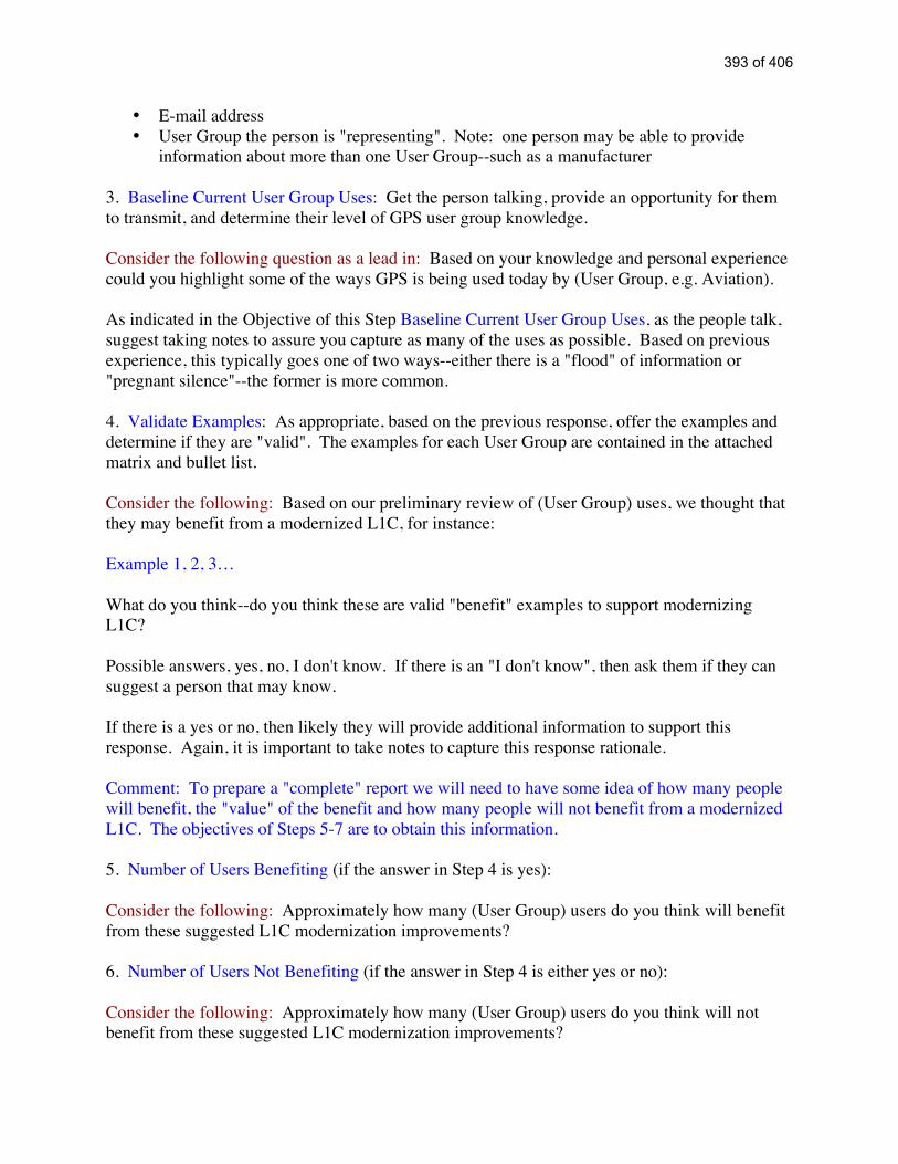
• E-mail address• User Group the person is "representing". Note: one person may be able to provide
information about more than one User Group--such as a manufacturer
3. Baseline Current User Group Uses: Get the person talking, provide an opportunity for themto transmit, and determine their level of GPS user group knowledge.
Consider the following question as a lead in: Based on your knowledge and personal experiencecould you highlight some of the ways GPS is being used today by (User Group, e.g. Aviation).
As indicated in the Objective of this Step Baseline Current User Group Uses, as the people talk,suggest taking notes to assure you capture as many of the uses as possible. Based on previousexperience, this typically goes one of two ways--either there is a "flood" of information or"pregnant silence"--the former is more common.
4. Validate Examples: As appropriate, based on the previous response, offer the examples anddetermine if they are "valid". The examples for each User Group are contained in the attachedmatrix and bullet list.
Consider the following: Based on our preliminary review of (User Group) uses, we thought thatthey may benefit from a modernized L1C, for instance:
Example 1, 2, 3…
What do you think--do you think these are valid "benefit" examples to support modernizingL1C?
Possible answers, yes, no, I don't know. If there is an "I don't know", then ask them if they cansuggest a person that may know.
If there is a yes or no, then likely they will provide additional information to support thisresponse. Again, it is important to take notes to capture this response rationale.
Comment: To prepare a "complete" report we will need to have some idea of how many peoplewill benefit, the "value" of the benefit and how many people will not benefit from a modernizedL1C. The objectives of Steps 5-7 are to obtain this information.
5. Number of Users Benefiting (if the answer in Step 4 is yes):
Consider the following: Approximately how many (User Group) users do you think will benefitfrom these suggested L1C modernization improvements?
6. Number of Users Not Benefiting (if the answer in Step 4 is either yes or no):
Consider the following: Approximately how many (User Group) users do you think will notbenefit from these suggested L1C modernization improvements?
393 of 406

7. Value of the Benefit (if the answer in Step 4 is yes):
Consider the following: Any idea or opinion on the value of these benefits, in terms of dollarvalue, time and effort saved, safety benefits, expanded demand for GPS receivers or anythingelse that could be used to determine the value of the L1C modernization benefits for the (UserGroup).
8. Other Potential Benefits of L1C Modernization (if the answer in Step 4 is either yes or no)
Consider the following: In light of the fact that a modernized L1C signal may improve accuracy,provide better performance in interference environments and be easier to acquire and track, canyou think of any other benefits that (User Group) may derive from a modernized L1C?
Likely answers to this question will either be yes or no. If yes, repeat Steps 5,6,7.
Comment: L1C modernization will take several years to be an end-state user reality. GPS usergrowth projections are available in various government and private reports, such as the DOCreport and Frost and Sullivan. But, believe it is reasonable to also get a growth projection for theperson(s) being interviewed.
9. Growth Projection:
Consider the following: Based on your knowledge and experience with (User Group) GPS users,how rapidly do you think GPS use will grow over the next 5-10 years?
10. Follow on Contact: It is not uncommon for an interviewee or interviewer to "think ofsomething else" or have follow-on questions.
Consider the following: Tell the interviewee that you are going to go back to the office and typeup a record of the discussion. Before submitting the record of discussion to the JPO, you wouldlike to send it to him/her for his review and comment--just to make certain you got theinformation right and in case he/she thinks of "something else". Also, mention—as in Step 1--Everything that has been discussed will be “non-attribution” unless you have no objection toreferencing your name/company with the information provided. Ask him/her if there is noobjection.
394 of 406

Economic Benefits
Determine a methodology for estimating the potential monetary benefits of L1modernization for the manufacturers and GPS user groups.
Quantification of the benefits for GPS civil applications is a complex task. Ultimately,the benefits to the civil community are measured in dollars. Improvements in safety areoften an important motivation for using GPS. In all cases, at a minimum, safety ispreserved (i.e. safety is never traded for increased profitability). However, in virtuallymost situations, the major motivation for implementing GPS applications is someeconomic benefit.
The economic benefit of a civil GPS/L1 modernization application is typically a functionof one or more of the practical uses that have been outlined in the individual user groupreports (attachment 2). The economic benefit may also be a function of other factors thathave nothing to do with GPS/L1. For example, regulatory and institutional factors canimpact the profitability of a GPS application irrespective of the actual real-worldrequirement. Also, the economic benefit of a civil GPS/L1 modernization applicationmay be a function of other enabling technologies, such as data communications (e.g.Public Safety/Security) and database capabilities (e.g. Surface Transportation).
Consequently, the assessment of the benefit of a civil application is often confounded bydependence on non-technical factors (such as regulatory and institutional issues) as wellas requirements for non-GPS enabling technologies.
The Team concluded that the ideal situation would be to obtain an estimate of theeconomic benefits associated with an L1 modernization option from each manufacturerand user group. In turn, this information could be used to develop a “business case” forinvestment in L1 modernization.
However, the Team recognized that the likelihood of this ideal situation was small and amore realistic methodology would be required. In light of the inter- and intra-dependencies discussed above, the likelihood of obtaining useful data from all of thosecontacted and completing such an effort from zero initial data would likely exceed theavailable time and resources.
Hence, the Team developed the following methodology for estimating economic benefitsof L1 modernization:
1. Obtain publicly available information from a cross-section of civil GPS marketanalyses, surveys and reports. Note: There are several commercial productscurrently available. However, the cost of obtaining these products is outside theallocated budget (e.g. Frost and Sullivan, Ovum, Allied Business Intelligence,Price Waterhouse Coopers, etc.).
A395 of 406

2. Obtain publicly available information used to justify the investment and planneddevelopment of Galileo.
3. Determine “high level” civil categories of use that will be in-line with theinformation obtained from the publicly available market analyses, surveys andreports and the civil user group categories studied in attachment 2 (e.g. LocationBased Services, Aviation, Agriculture, Timing, etc.)
4. As appropriate, place each of the civil user groups under the appropriate “highlevel” category. For instance: High Level Category—Telematics; possible CivilUser groups under this category could be: Aviation, Surface Transportation, Rail,Mining and Construction, Maritime and Waterways.
5. Using information obtained from interviews, literature searches, and JPO suppliedGPS-III data estimate the percent of increased GPS utility resulting from L1modernization for each of the civil user groups.
6. Estimate the overall percent of increased GPS utility for each of the High LevelCategories based on the estimated user group improvements.
7. Summarize the High Level Category estimates to determine the overall projectedeconomic benefit of an L1 modernization.
The Team recognized that this methodology would produce a rough order of magnitudeestimate of the civil economic benefit. However, resource and time constraints limitedother alternatives.
It was determined that a rigorous assessment to determine the civil economic benefits ofGPS would be a valuable tool for guiding future GPS modernization strategies andinvestments.
The remaining sections of this Attachment will address the specific steps taken todetermine a rough order of magnitude estimate of the civil economic benefits of L1modernization.
Step 1: Obtain publicly available information from a cross-section of civil GPS marketanalyses, surveys and reports. Note: There are several commercial products currentlyavailable. However, the cost of obtaining these products is outside the allocated budget(e.g. Frost and Sullivan, Ovum, Allied Business Intelligence, Price Waterhouse Coopers,etc.).
Although there are several commercial products, obtaining specific information regardingthe findings and conclusions of these market analyses, surveys and reports proved to be adefinite challenge. Fortunately, many of the companies “selling” their reports offeredsnapshot views of the findings in their sales literature and issued public statements/press
396 of 406

releases regarding the content of their reports. Based on these sources, and relying onpublicly available information, the following data was compiled:
Projections for Location Technologies and Associated Markets
Source Mkt Proj ($) Year MarketOnStar $2.3B 2005 TelematicsStrategis Group $5.3B 2005 TelematicsFrost & Sullivan $7.2B 2005 TelematicsOvum $20B 2006 Mobile Location ServicesOvum $4.7B 2004 Information ServicesThe Kelsey Group $11B 2005 Location ServicesDain Rauscher WesselsReport $19B 2005 Telematics
UBS Warburg $24B 2005 Wireless VehiclesAllied Business Intelligence $14B 2005 Commercial GPSAllied Business Intelligence $8B 2005 TelematicsRoland Berger StrategyConsultants $11B 2004 Telematics
UBS Warburg LLC $47.2B 2010 Telematics - AllUBS Warburg LLC $7B 2010 Telematics Service ProvidersStrategis Group $32B 2005 Wireless Location ServicesDataquest $3B 2003 Data Subscribers
ABI $8B 2005IVIS - In-Vehicle Information,Navigation, Communications andRoadside Technology
Allied Business Intelligence $60B 2005 Global GPS equipment shipmentmarket value
Allied Business Intelligence $10B 2005 GPS equipment shipments forcommunications
Allied Business Intelligence $22B 2005 GPS equipment shipments for in-vehicle navigation systems
Strategis Group $81B 2005 European Wireless Location Services
Allied Business Intelligence $40.7B 2006
Covers the US, Europe, Japan, LatinAmerica and the rest of the worldmarkets for LBS and wirelesssubscribers, service revenues, GPSequipment and components,mcommerce, vcommerce andBluetooth.
Bear Stearns $3 trillion 2005
iAppliances -- intelligent, internet-enabled devices and services -Mobile/Personal InformationSolutions, ConsumerElectronics/Entertainment Devices
397 of 406

Note: Lately, "telematics" has mainly been used to describe "automotive telematics," theuse of computers and telecommunications to enhance the functionality of motor vehicles;for example, wireless data applications in cars, trucks, and buses. However, the originaldefinition of telematics is the blending of computers and telecommunications.
An example of the type of available public information providing a GPS economicinsight is well illustrated in this January 5, 2004 Press Release from ABIresearch:
“As consumer awareness of global position systems (GPS) increases, so has productinnovation and total market revenue. While roughly half of the market today consists ofsales of automotive and asset-tracking equipment, these segments will still continue togrow at rates faster than that of the broader market for GPS equipment. Despite thestrength of these markets, new segments are constantly emerging for GPS applications,driving demand for gear as diverse as people-tracking devices and GPS golf systems. Thenet result will be a market worth over $22 billion by 2008, according to technologymarket research firm ABI.
Companies like Garmin, Wherify Wireless and Navman are synonymous with integratingGPS receivers into innovative form factors. Advances in GPS integrated circuits (ICs)will fuel this trend across the entire industry. Sony's recent announcement unveiling aminiature, single-chip IC provides further evidence that more of these novel applicationsare likely in an ever-increasing range of devices.
According to a recent study from ABI, unit growth in ICs, the brains behind the devices'positioning capabilities, will likely be at about 35% compounded annually over the nextfive years. Revenue growth will be strong, but not as spectacular as unit growth, duemainly to pricing pressure.
The study, "GPS World Markets: Opportunities for Equipment and IC Suppliers,"examines the current status and trends of the global positioning systems industry.Covered areas include wireless and in-vehicle navigation, as well as growing segmentssuch as recreation, communication, people tracking, marine and surveying, among others.For each segment, total market value is forecasted to 2008 in addition to regional totals.An analysis of key market drivers and barriers for each segment is presented. The reportalso quantifies the market for GPS IC shipments, ASP and revenue to 2008.
398 of 406

Step 2: Obtain publicly available information used to justify the investment and planneddevelopment of Galileo.
On 20 November 2001 PriceWaterhouseCoopers, with the support of Ovum, Willis,Denton Wilde Sapte, and Deutsche Bank, publicly released a report to support thedevelopment of a business plan for Galileo. This report provided the following cost-benefit information to justify a Galileo investment:
1. The estimated cost of Galileo was Euro 3.6 billion. The EC and ESA have budgeted Euro1.25 billion for the Development phase and application development. This leaves a balanceof Euro 2.35 billion to be spent on deploying the system. This will need to be met by acombination of public sector support and private sector funding.
2. It is very important that Galileo should commence service by 2008. The market will be in arapid growth phase by then, and GPS III (a more sophisticated version) is expected tocommence operations 1 or 2 years thereafter. Galileo will only become established if it is inthe market in time to gain acceptance in the launch of new equipment and services which willaccompany this change. If that is achieved we estimate that the annual sale of Galileo receiverswill increase from 100 [million] in 2010 to some 875 [million] by 2020; which representsmarket penetration rising from 13% to 52%.
3. Estimated Galileo Revenues in millions of Euros:
Table 2 Estimated revenues by application (Euro m 2001 prices)
Application 2010 2015 2020
Personal communications and location 48 276 288Commercial Aviation - 20 100Police and Fire (Pedestrian resource management) 1 10 20Oil and Gas – Rig Positioning 1 8 15Oil and Gas – Land and transition zone seismic exploration 2 9 10Others 14 47 82Total 66 370 515
399 of 406

Figure 3 Revenue scenarios (2001 prices)
20082009 201020112012 20132014201520162017 20182019202020212022 20232024202520262027
Blue line reflects a 5% chipset royalty; red line is a 2% chipset royalty
4. The benefits principally arise from air traffic control, marine navigation, and routeguidance for motor vehicles. The largest and most robust are generated from theaviation and maritime industries.
Table 4 Value of Main Benefits (Euro m 2000 prices)Description of Benefit Annual values NPV
2010
2020 2008-2020Improvements in air traffic control
cost savings for airlines 166 3,381
7,476Time savings for passengers 82 1,66
75,447
Marine navigation 81 2,638
4,864Total 329 7,68
617,787
The previous study for the Commission implied higher total benefits of Euro 27.2 billionNPV (using our discount rates) largely because it estimated greater benefits from routeguidance.
Even with these more conservative assumptions on user benefits and the exclusionof producer benefits we estimate total benefits at Euro 17.8 billion in NPV termsand costs at Euro 3.9 billion, implying a benefit:cost ratio of 4.6. This should beregarded as a strongly positive ratio. For example public sector transport projectsin the UK, on the underground railway and on roads, often proceed with rations ofabout 3.0.
400 of 406

Steps 3 & 4: Determine “high level” civil categories of use that will be in-line with theinformation obtained from the publicly available market analyses, surveys and reportsand the civil user group categories listed in attachment 2 (e.g. Location Based Services,Aviation, Agriculture, Timing, etc.)
As appropriate, place each of the civil user groups under the appropriate “high level”category. For instance: High Level Category—Telematics; Civil User groups under thiscategory: Aviation, Surface Transportation, Rail, Mining and Construction, Maritime andWaterways.
The Team developed the following set of user groups as a basis for assessing the realworld value of modernizing L1:
• Location Based Services/Recreation• Scientific• Aviation• Agriculture• Surface Transportation• Mining & Construction• Surveying/Civil Engineering• Public Safety/Security• Timing• Rail• Space• Environment• Maritime and Waterways
The individual reports for each of these user groups are contained in Attachment 2.
Steps 3 and 4 of the Team methodology proved to be closely linked with each other.Information obtained during Step 1 actually defined the “high level” civil categories forwhich there was publicly available information. Those categories are:
• Mobile and Wireless Location Services• Information/Data Services• Commercial GPS• In Vehicle Information and navigation services—“telematics”
401 of 406

The next task was to map the user groups into the “high level” civil categories. Thismapping was subjective. It was based upon a review of the user group responsesregarding how they actually use GPS and the perceived “population” that formed thebasis of the individual market analyses. The exact population is not known because theTeam did not have access to the actual market analyses.
The final Team mapping of the 13 user groups into the 4 “high level” civil categories isas follows:
Mobile and Wireless Location ServicesLocation Based Services/Recreation
Information/Data ServicesEnvironmentScientificPublic Safety/Security
Commercial GPS Mining & Construction
AgricultureTimingMaritime and WaterwaysSurveying/Civil Engineering
In Vehicle Information and navigation services—“telematics”Surface TransportationAviationRailSpace
One “high level” civil category referenced in the market analyses completed by AlliedBusiness Intelligence but did not correlate with the user group categories surveyed by theTeam was “GPS Equipment Shipments”. It was concluded that this category representedthe aggregate projected market value of equipment sales across the spectrum of all usergroups, both domestic and international. The Team agreed that these projected dollarvalues should be considered when estimating the projected dollar value of each of the 4high level civil categories.
The next task was to estimate the projected dollar value of each of the high level civilcategories. This estimate was based on the GPS market analyses information obtained inStep 1 and the Galileo investment information obtained in Step 2. The overall objectiveof this task was to approximate a “rough order of magnitude” dollar value, recognizingthat the approximation would be a Team consensus based on the publicly availableinformation.
402 of 406

The Team determined that the following figures for each of the high level civil categoriesrepresented a reasonable rough order of magnitude estimate of their 2005 projected dollarvalues:
• Mobile and Wireless Location Services: $16B• Information/Data Services : $2.5B• Commercial GPS : $11B• In Vehicle Information and navigation services—“telematics”: $7B
403 of 406

Step 5: Using information obtained from the interviews, literature searches, and JPOsupplied GPS-III data estimate the percent of increased GPS utility resulting from L1modernization for each of the civil user groups.
This task required a thorough review of the data/information provided in the attachments,discussion, and consensus on a reasonable estimate of the potential increase in GPSutility resulting from L1 modernization.
The degree of potential increase is clearly dependent upon the type of improvements thatwould be made to L1. For instance, if an L1 modernization decision was made to LowerSignal Thresholds for Navigation (Power & Dataless Channel) then there would be adefinite benefit for some user groups. Specifically, for the Location BasedServices/Recreation user group, a stronger signal and data-less channel improves theability to rely on GPS services in challenged environments, such as under forest cover,beside tree-lined roads, in urban canyons and inside buildings (e.g., 911 applications).
Recognizing that the extent and options for L1 modernization have not been determined,an attempt was made to estimate the range of potential increased GPS utility for eachindividual user group. For instance, continuing with the example in the precedingparagraph—if a positive decision was made to Lower Signal Thresholds for Navigation(Power & Dataless Channel), the percent of increased GPS utility for the Location BasedServices/Recreation user group would be greater as compared to the percent of increasedGPS utility if a decision was made not to Lower Signal Thresholds for Navigation (Power& Dataless Channel).
The Team decided to adopt a pessimistic/optimistic approach for determining the rangeof potential increased GPS utility for each user group. Clearly, the lower bound forincreased utility would be zero—assuming a worse possible case scenario. To estimatean upper bound, the information in Attachment 2 was carefully reviewed and analyzed.The upper bound for each of the user groups was estimated as follows:
• Location Based Services/Recreation: 4%• Scientific: 2%• Aviation: 0.5%• Agriculture: 3%• Surface Transportation: 4%• Mining & Construction: 3.5%• Surveying/Civil Engineering: 1%• Public Safety/Security: 3%• Timing: 0.5%• Rail: 2%• Space: 0.5%• Environment: 0.5%• Maritime and Waterways: 1%
404 of 406

Step 6: Estimate the overall percent of increased GPS utility for each of the High LevelCategories based on the estimated user group improvements.
Given the 13 user groups mapping into the 4 “high level” civil categories—Step 3/4 andthe estimated upper bound percent of increased GPS utility—Step 5—the percent ofpotential benefit for each of the high level civil categories is as follows:
Mobile and Wireless Location Services: 4%Location Based Services/Recreation: 4%
Information/Data Services: 5.5%Environment 0.5%Scientific: 2%Public Safety/Security: 3%
Commercial GPS: 9% Mining & Construction: 3.5%
Agriculture: 3%Timing: 0.5%Maritime and Waterways: 1%Surveying/Civil Engineering: 1%
In Vehicle Information and navigation services—“telematics”: 7%Surface Transportation: 4%Aviation: 0.5%Rail: 2%Space: 0.5%
405 of 406
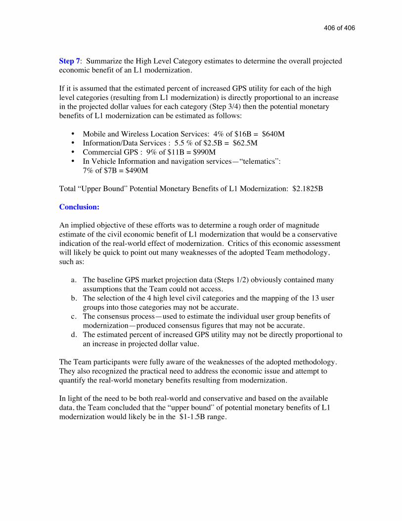
Step 7: Summarize the High Level Category estimates to determine the overall projectedeconomic benefit of an L1 modernization.
If it is assumed that the estimated percent of increased GPS utility for each of the highlevel categories (resulting from L1 modernization) is directly proportional to an increasein the projected dollar values for each category (Step 3/4) then the potential monetarybenefits of L1 modernization can be estimated as follows:
• Mobile and Wireless Location Services: 4% of $16B = $640M• Information/Data Services : 5.5 % of $2.5B = $62.5M• Commercial GPS : 9% of $11B = $990M• In Vehicle Information and navigation services—“telematics”:
7% of $7B = $490M
Total “Upper Bound” Potential Monetary Benefits of L1 Modernization: $2.1825B
Conclusion:
An implied objective of these efforts was to determine a rough order of magnitudeestimate of the civil economic benefit of L1 modernization that would be a conservativeindication of the real-world effect of modernization. Critics of this economic assessmentwill likely be quick to point out many weaknesses of the adopted Team methodology,such as:
a. The baseline GPS market projection data (Steps 1/2) obviously contained manyassumptions that the Team could not access.
b. The selection of the 4 high level civil categories and the mapping of the 13 usergroups into those categories may not be accurate.
c. The consensus process—used to estimate the individual user group benefits ofmodernization—produced consensus figures that may not be accurate.
d. The estimated percent of increased GPS utility may not be directly proportional toan increase in projected dollar value.
The Team participants were fully aware of the weaknesses of the adopted methodology.They also recognized the practical need to address the economic issue and attempt toquantify the real-world monetary benefits resulting from modernization.
In light of the need to be both real-world and conservative and based on the availabledata, the Team concluded that the “upper bound” of potential monetary benefits of L1modernization would likely be in the $1-1.5B range.
406 of 406