gpr applications by using uwb pulse …ethesis.nitrkl.ac.in/6508/1/e-18.pdf · 1 gpr applications...
TRANSCRIPT

1
GPR APPLICATIONS BY USING UWB PULSE GENERATION
A Thesis Submitted in Partial Fulfillment Of the Requirements for the Degree of
Bachelor of Technology In
Electronics and Instrumentation Engineering By ABHISEK PRUSTY
Department of Electronic & Communication Engineering
National Institute of Technology
2010-14
National Institute of Technology, Rourkela

2
NATIONAL INSTITUTE OF TECHNOLOGY ROURKELA
C E R T I F I C A T E This is to certify that the thesis entitled “GPR APPLICATIONS BY USING UWB
PULSE GENERATION”, submitted by ABHISEK PRUSTY (110EI0249 ) for the
award of Bachelor of Technology Degree in ‘ELECTRONICS and
INSTRUMENTATION’ Engineering at the National Institute of Technology (NIT),
Rourkela is under my supervision. DATE: Prof. SUBRATA MAITI
PLACE: Department of Electronics and Communication
NIT Rourkela
National Institute of Technology, Rourkela

3
ACKNOWLEDGEMENT I would like to take this opportunity to express my gratitude and sincere thanks to my respected
guide, Prof. SUBRATA MAITI for his guidance, insight, and support he has provided
throughout the course of this work. The present work would never have been possible without
his vital inputs and mentoring.
I would like to thank all my friends, faculty members and staff of the Department of Electronics
and Communication Engineering, N.I.T. Rourkela for their extreme help throughout course.
ABHISEK PRUSTY (110EI0249) National Institute of Technology, Rourkela
4
ABSTRACT
In this work of my last year venture I speak to a low many-sided quality and ease ultra-
wideband (UWB) pulse generator for GPR requisitions. Here I have actualized one UWB pulse
generator circuit. The UWB pulse generator is based on the avalanche transistor. This pulse
generator circuit provides a Gaussian pulse when it is given by a square wave of an external
triggered signal. And further more when it is enacted with 3 kHz square wave, it creates 13ns
span Gaussian pulse.
National Institute of Technology, Rourkela
5
Contents Pages
1 Ground Penetrating Radar 2……………………………………… 08-13
1.1 Introduction…………………………………………… 09
1.2 Applications…………………………………………... 09
1.3 GPR Principle …………………………………………10
1.4 Description of a time domain GPR…………………… 12
1.5 Goal of the thesis……………………………………… 13
1.6 Conclusion…………………………………………….. 13
2 UWB Pulse Generation Technology …………………………… 14-18
2.1 Introduction……………………………………………... 15
2.2 Methods to approach…………………………………….. 15
2.2.1Transistor based UWB pulse generator…………….. 15
2.2.2Avalanche transistor based UWB pulse generator…. 17
2.3 Conclusion………………………………………………. 18
3 IMPLEMENTATION OF THE PULSE GENERATOR CIRCUITS 20-25
3.1 Introduction ………………………………………………. 20
3.2. Avalanche transistor based UWB pulse generator……….. 20
3.3 Conclusion………………………………………………… 25
4 Summary and Conclusion …………………………………………. 26-27
4.1 Summary ………………………………………………….. 27
4.2 Scope of the future work …………………………………... 27
4.3 Conclusion ……………………………………………….... 27
BIBLIOGRAPHY……………………………………………………. 28
6
List of Figures Pages 1.1 Ground Penetrating Radar block diagram. . . . . . . . . . . . . . . . . . 12
2.1 BJT based Pulse generator architecture . . . . . . . . . . . . . . . . . . 16
2.2 Control Signals and generated Gaussian pulse. . . . . . . . . . . . . 16
2.3 Avalanche transistor UWB pulse generator. . . . . . . . . . . . . . . 17
7
3.1 UWB pulse Generator using avalanche transistor . . . . . . . . . . 21
3.2 Simulated circuit and Simulated Result . . . . . . . . . . . . . . . . . …21
3.3 Photo of the Implemented circuit on Breadboard. ……………..22
3.4 Photo of the OUTPUT of the Implemented circuit……………..24
.
8
Chapter 1
Ground Penetrating Radar
9
1.1 Introduction Ground Penetrating Radar is a subset of the entire radar frameworks. GPR is additionally
regularly called as Surface Penetrating Radar (SPR). These days, GPR is a tremendous and
quickly developing engineering and every day the amount of its provisions is as of now
developing. Finding pipes and links, civil designing (investigation of extension, seeking voids),
security, antiquarianism examination, geophysical overview & confirmation and ice mapping are
few illustrations of its requisition. The working rule of GPR is focused around Maxwell's
comparison of EM wave spread in inhomogeneous sub-surface media. It couples EM waves in
the ground and examines or accepts the backscattered echoes. The EM wave will be back-
scattered focused around any electrical parameters differentiates in the ground. The uncommon
property of GPR is that it can recognize echoes because of every one of the three sorts of
electrical parameters contrasts, i.e. Permeability, conductivity and electric resistivity. This
implies that a GPR framework has potential for recognizing and spotting both metallic and non-
metallic covered targets focused around the reverberation attributes.
1.2 Applications
Presently-a-days advancement of GPR has been one of proceeding specialized development
generally provisions driven, But according to the necessities GPR has gotten all the more
requesting, so the gear, different methods and Data handling routines have been created and
refined.
GPR has been used in the following applications:
• Examinations in Archeological
• Building condition assessment
• Bridge deck analysis
• Borehole inspection
• Land investigation
10
• Detection of buried and undergrounded mines
• Forensic investigations
• Geophysical investigations
• Medical imaging
• Pipes and cable detection
1.3 GPR Principle
In nowadays Ground Penetrating Radar (GPR) is turned into a standout amongst the most
guaranteeing advances for Close discovery and better identification of covered Anti-Personnel
and Anti-tank Landmines, on the grounds that it can catch non-metallic protests in the sub-
surface. The working rule of GPR is it sends the Electro-Magnetic waves into the ground and
specimens the backscattered Echoes. One of the way of GPR is that echoes could be recognized
from every one of the three sorts of electrical parameters contrasts, i.e. this kind of nature shows
that the GPR framework has the capacity for looking and recognizing both metallic and non-
metallic undergrounded targets. In GPR the reception apparatuses could be checked over the
surface near the ground. The EM wave controlled into the ground will backscatter on any
electrical parameter irregularity. At that point collector courses of action and specimens the
backscattered echoes after gained by beneficiary reception apparatus. FIG 1.1 shows a block
diagram of ground penetrating radar system [1]. Fundamentally first and the biggest
reverberation are a result of the interface between air and ground and the consequent echoes are
because of the impression of the target or because of the vicinity of jumble in the subsurface. A
2d or 3d picture could be handled by the GPR by moving the reception apparatuses on a 1d or 2d
framework. Not at all like the metal locator might the GPR be utilized to recognize non-metallic
targets, which discovers substantial requisition in AP land mine discover.
Ground Penetrating Radar is classified in 2 types.
• Time Domain GPR
Amplitude modulated GPR
Carrier free GPR
• Frequency Domain GPR
Linear Sweep GPR
Stepped Frequency GPR
11
Time domain GPR is further divided in to two categories 1st one is amplitude modulated and 2nd
one is carrier free GPR. The principle of time domain GPR is to send a pulse at a particular PRF
into the ground and then to record the scattered back echoes. The duration of the pulse is kept for
good depth resolution. A pulse along with a carrier frequency is sent by the amplitude modulated
GPR. The carrier frequency modulation is done by a square wave envelope. The short pulse
duration is achieved using a mono-cycle. The central frequency of the mono-cycle as a range of
few MHz to few GHz depending upon the application. The central frequency of mono-cycle is
same as the 3db bandwidth of the emitted pulse.
The increase in demand of a higher bandwidth let to a second category of time domain GPR i.e.
carrier free GPR. A pulse without carrier is sent by the GPR. The carrier free pulse width as the
order of some Pico-second. Any type of pulse can be used by this GPR, but generally a Gaussian
pulse is used. The carrier free GPR is also known as UWB GPR.
The second category of GPR system is frequency domain GPR. Which is classified into two
types one is linear sweep GPR and another is stepped frequency GPR. In the 1st type frequency
modulation of a continuous wave is done with a linear sweep and named as FMCW GPR. The
FMCW GPR system transmits continuously a time vary carrier frequency with a help of vco
between a given ranges of frequencies. The frequency is steeped in accordance to a saw tooth or
triangular function in a certain dwell time. The scattered back signal is received and mixed with
the emitted wave. The transmitted and received wave frequency difference is a function of the
depth of the target. The poor dynamic range is one of the major disadvantage of FMCW radar.
Simultaneous reception and transmission of the signal is done by FMCW. The smaller
backscattered signal is hidden by the leakage signal between the antennas. The following
drawback has led to the decrease in demand of FMCW for GPR and the demand of step
frequency RADAR has increased.
A step frequency GPR steps to a range of frequency with the help of a frequency synthesizer. A
carrier wave of higher stability is radiated and mixed with received signal at each frequency with
the help of quadrature mixer. The sampling of the I and Q base band signals is done with the help
of high precision and low speed AD converter. The comparison between the amplitude and phase
of the received and transmitted signal is done at each frequency.
12
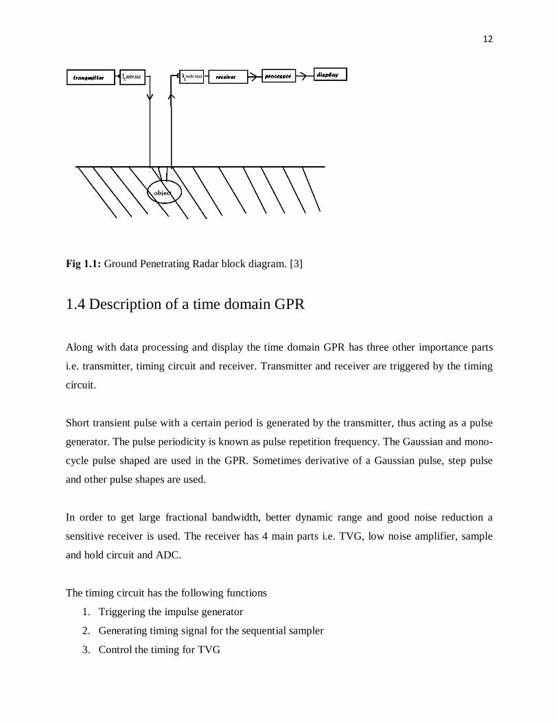
Fig 1.1: Ground Penetrating Radar block diagram. [3] 1.4 Description of a time domain GPR
Along with data processing and display the time domain GPR has three other importance parts
i.e. transmitter, timing circuit and receiver. Transmitter and receiver are triggered by the timing
circuit.
Short transient pulse with a certain period is generated by the transmitter, thus acting as a pulse
generator. The pulse periodicity is known as pulse repetition frequency. The Gaussian and mono-
cycle pulse shaped are used in the GPR. Sometimes derivative of a Gaussian pulse, step pulse
and other pulse shapes are used.
In order to get large fractional bandwidth, better dynamic range and good noise reduction a
sensitive receiver is used. The receiver has 4 main parts i.e. TVG, low noise amplifier, sample
and hold circuit and ADC.
The timing circuit has the following functions
1. Triggering the impulse generator
2. Generating timing signal for the sequential sampler
3. Control the timing for TVG

13
1.5 Goal of the thesis GPR can be used for both metallic and non-metallic objects in the subsurface. GPR, with a large
bandwidth system efficiently detects small targets buried into the air-ground interface. For a
better depth resolution and detailed echo a larger bandwidth is required. This need for a larger
bandwidth has led to the use of UWB GPR. The range resolution of a radar system is defined as
“the ability to distinguish between two targets solely by the measurement of their ranges
(distance from the radar); usually expressed in terms of the minimum distance by which two
targets of equal strength at the same azimuth and elevation angles must be spaced to be
separately distinguishable”.
In UWB GPR, UWB and ultra-short pulse is transmitted into the ground.one of the critical
functions in the UWB GPR is UWB pulse generation. Goal of my thesis is generating UWB
pulse using simple circuit elements like transistors, capacitors and resistors.
1.6 Conclusion
GPR is one of the most advanced and promising technology for buried object detection. The
range resolution is directly proportional to the bandwidth of the system. The UWB GPR has been
developed to meet the larger bandwidth requirement. The major challenges faced by GPR
research community are the generation and reception of UWB pulse and to design at a reliable
UWB GPR system at a releasable cost.
14
Chapter 2
UWB Pulse Generation
Technology
15
2.1 Introduction Pulsed UWB uses pulses with a very short pulse width, usually of the order of nanoseconds or
some nanoseconds. This helps in spreading of the radio power signal over a wider bandwidth.
This feature provides high time and range resolution, reduced multipath feeding, lower power
and complexity, high data rates and low probability of unwanted detection. Pulsed UWB
transceivers with low cost and low power find large application in wireless communication, bio-
medical instrumentation, wireless personal and sensor networks and inter-chip communication.
2.2 technique and methods I have approached:
Because of the limitation of the instruments and devices, we chosen UWB pulse generators
based on transistors. In this project we have chosen two transistor UWB pulse generators.
First one is based on normal transistors, and the second one based on avalanche transistor.
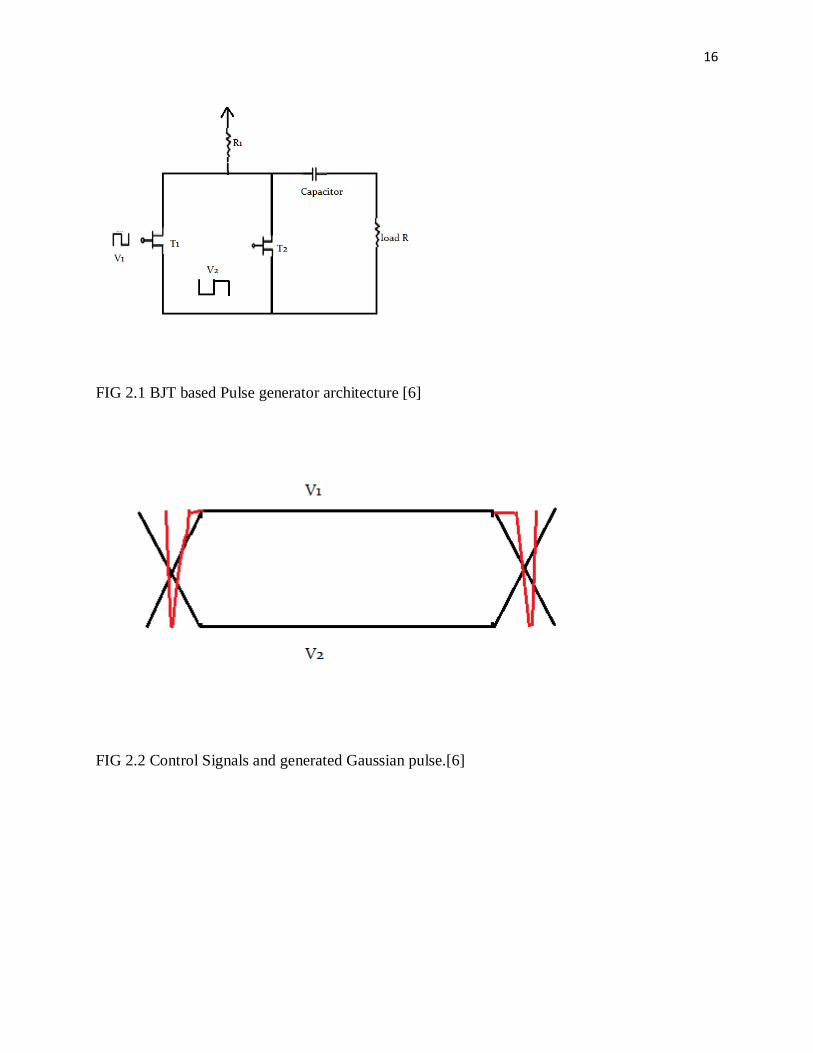
2.2.1 Transistor based UWB pulse generator: The circuit gives the Gaussian pulse when enacted by a square wave [4, 6]. This pulse generator
utilizes a basic normal emitter amplifier took after by RC high-pass filter. In this circuit we can
tune the pulse width term by differing the incline of the square wave. Beneath Figure indicating
that, V1 and V2 voltage level pole be in inverse stage. The two transistors along these lines are
individually in an off and on state. By assuming that transistor Tr1 is in "off "state and Tr2 in "on
"state, so V1 and V2 are individually low and high, the same transistors determined by the direct,
and inverse in stage, edge of the connected square wave indicator, create a Gaussian beat. The
focal point of the generator is low-unpredictability, minimal effort, and flexible, so we can utilize
this generator within a mixed bag of coordinated circuits UWB balance plans and systems.
16
FIG 2.1 BJT based Pulse generator architecture [6]
FIG 2.2 Control Signals and generated Gaussian pulse.[6]
17
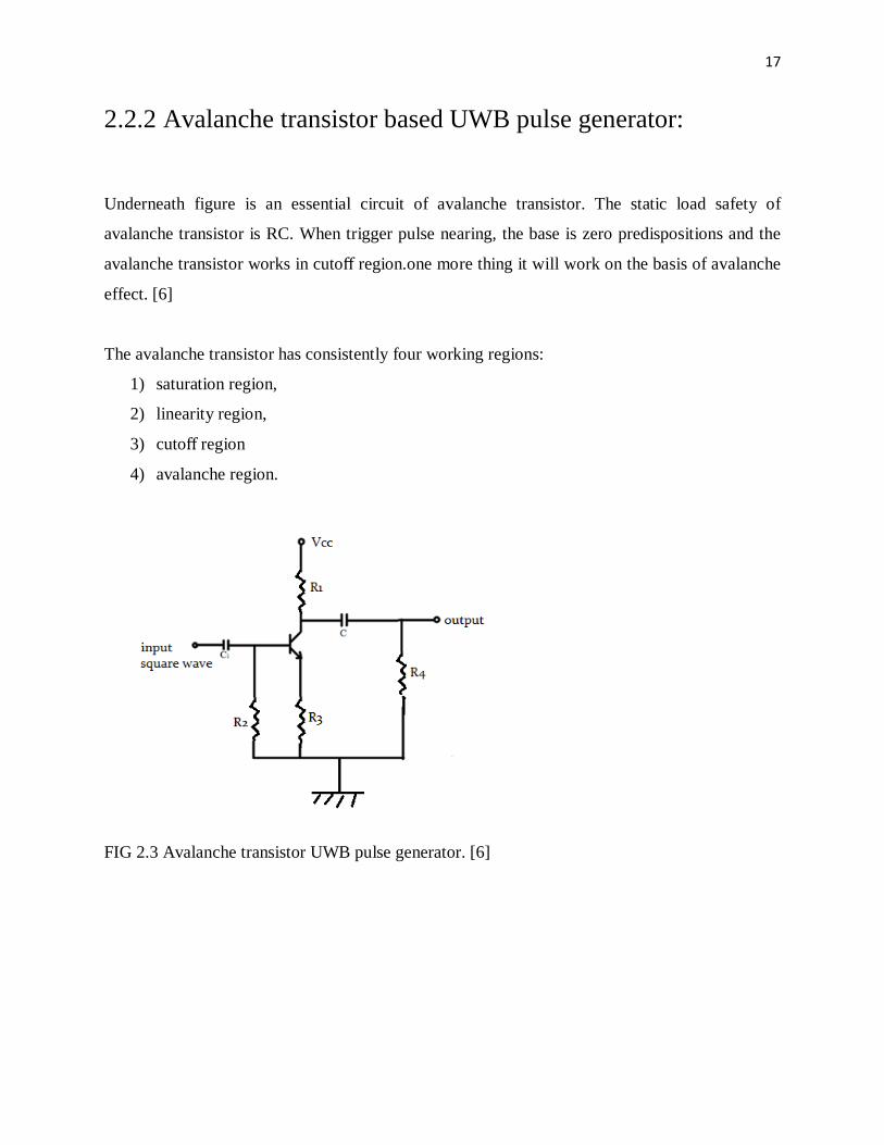
2.2.2 Avalanche transistor based UWB pulse generator:
Underneath figure is an essential circuit of avalanche transistor. The static load safety of
avalanche transistor is RC. When trigger pulse nearing, the base is zero predispositions and the
avalanche transistor works in cutoff region.one more thing it will work on the basis of avalanche
effect. [6]
The avalanche transistor has consistently four working regions:
1) saturation region,
2) linearity region,
3) cutoff region
4) avalanche region.
FIG 2.3 Avalanche transistor UWB pulse generator. [6]
18
2.3 Conclusion:
In view of the restriction of the instruments and gadgets, I picked UWB pulse generators focused
around transistors. In this venture we have picked two transistor UWB pulse generators. Initial
one is focused around ordinary transistors, and the second one focused around avalanche
transistor.
19
Chapter 3
IMPLEMENTATION OF
THE
PULSE GENERATOR
CIRCUITS
20
3.1 Introduction
In this work, I actualized one low-intricacy, ease UWB pulse generator circuits. I actualized the
the circuit is by utilizing the 2N5551 avalanche transistor, this circuit gives the Gaussian pulse
when initiated by a square wave data. This pulse generator utilizes a straightforward common
emitter amplifier took after by RC high-pass filter. In this circuit we can tune the pulse width
length of time by changing the incline of the square wave.
Anyway this one gave better and obliged yield in light of its avalanche effect.so I recognized just
this one. This pulse generator likewise utilizes a basic common emitter amplifier took after by
RC high-pass filter. This circuit likewise gives the Gaussian pulse when enacted by a square
wave.
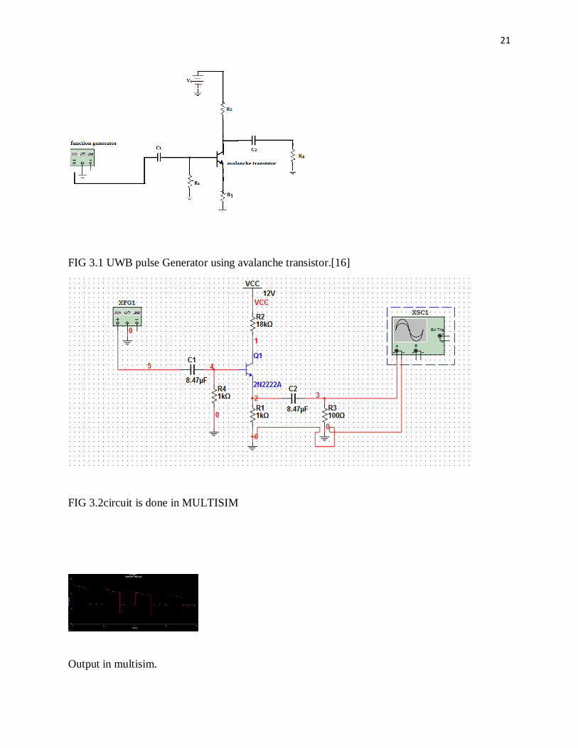
3.2 Avalanche transistor based UWB pulse generator
This pulse generator [15, 16] utilizes a straightforward common emitter amplifier emulated by
RC high-pass filter to produce UWB pulse. Here we utilized 2N5551 avalanche transistor to
produce UWB Gaussian pulse. What's more we utilized Rcc is 10 kilo ohm, Ccc is 0.47 µf, RBE
is 1 kilo ohm, RE is 1 kilo ohm and RL is 100 ohm. Also here we utilized dc power supply i.e.
Vcc is 12volts. Furthermore we reproduced the circuit by utilizing the MULTISIM 11.0
instrument. The reproduced circuit is indicated in figure below.
We mimicked or simulated the circuit. Here we utilized 3 khz square wave info with 10 volts
crest to top voltage, and we got the Gaussian pulse yield. At that point we actualized the same
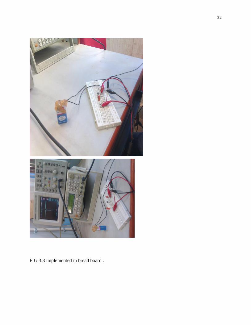
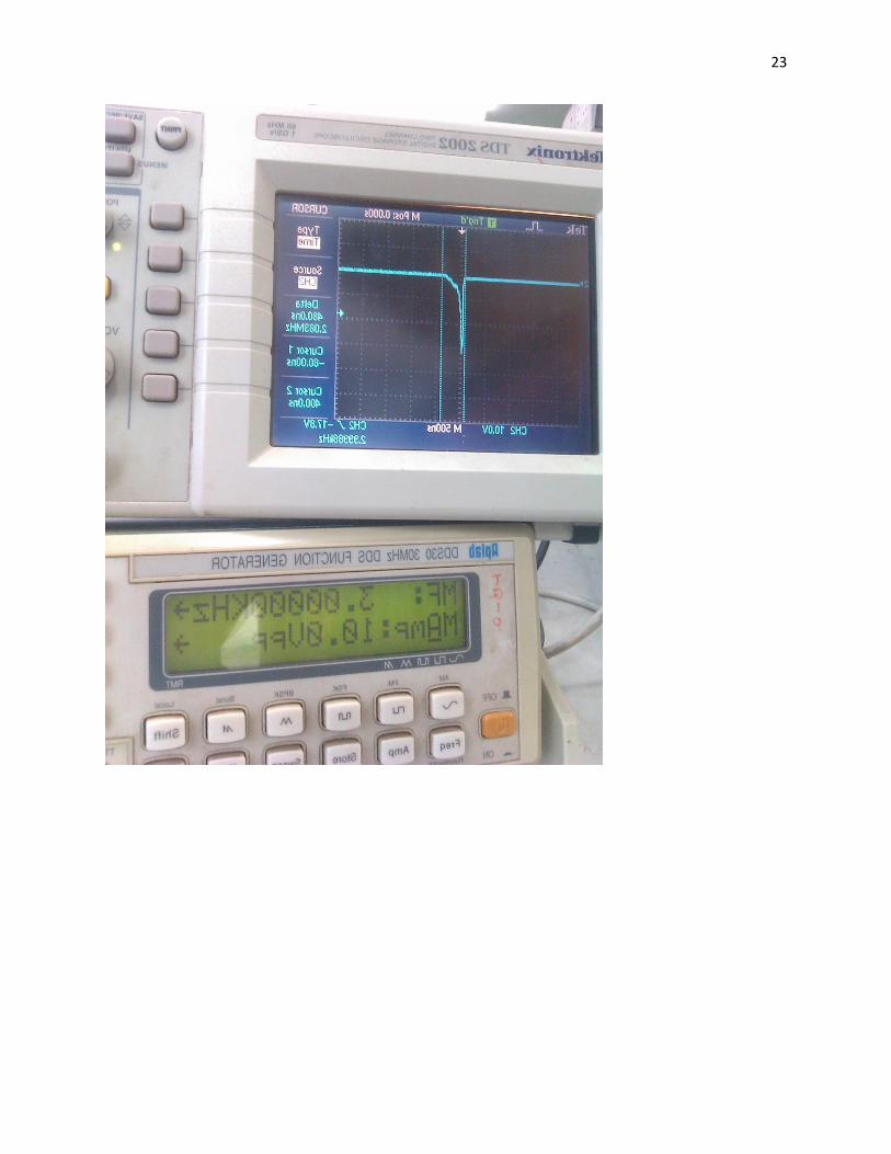
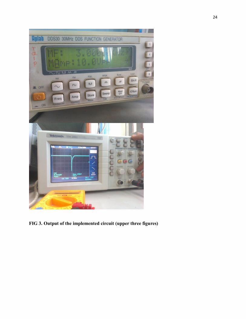
circuit with same values on the breadboard, and we accomplished the Gaussian beat basically. In
reproduction we got 2 ns length of time Gaussian pulse, however in handy usage we got 13ns
term Gaussian pulse (on bread board).
21
FIG 3.1 UWB pulse Generator using avalanche transistor.[16]
FIG 3.2circuit is done in MULTISIM
Output in multisim.
22
FIG 3.3 implemented in bread board .
23
24
FIG 3. Output of the implemented circuit (upper three figures)
25
3.3 Conclusion In this work we introduced a low many-sided quality and low UWB pulse generator building
design suitable for UWB GPR requisitions. The circuit gives a Gaussian beat when enacted by a
square wave indicator from signal generator. Here we utilized 3 kHz square wave info sign to
create Gaussian pulse. The recreated outcomes are given 2ns term Gaussian pulse, however the
handy comes about on breadboard given 13ns length of time Gaussian pulse. Here we showed
the Gaussian pulse era with lessened ringing levels, and great symmetry.

26
Chapter 4
Summary and Conclusion

27
4.1 Summary
In UWB GPR transmitter, one of the most critical function is UWB pulse generation. There are
many techniques that are used to generate UWB pulse. This project work implements one simple
circuit based on transistor to generate UWB pulse. The circuit is based on avalanche transistor.
The circuit was implemented on the breadboard and output waveform was observed on the
oscilloscope. The signal generator was used to generate the input signal. The practical result was
approximately equal to the simulated result.
4.2 Scope of the future work
There was a marginal difference between the simulated and practical result, a further theoretical
analysis can help us to understand this discrepancy. Simulation with other software like :
Multisim and P-Spice can help us understand the difference. Simulation with more practical
cases might give the comparable result. The results may improve by testing with precise
instruments. Proper soldering may also give good results.
4.3 Conclusion
One of the important blocks to realize high resolution GPR is UWB pulse generator. This
research work mostly focuses on a pulse generator based on a simple circuit. These circuits are
light weight and cost efficient. The UWB spec requirements are not met by the pulse generators.
Simulation tools and sophisticated instruments are required for high quality research in UWB
pulse generator. Further research to achieve cost efficient and reliable UWB generator will create
a huge impact in transforming the present generation of GPR technology.

28
Bibliography
[1] John C Cook. Radar transparencies of mine and tunnel rocks. Geophysics, 40(5):865–
885, 1975.
[2] David J Daniels. Ground penetrating radar. Institution of Electrical Engineers, 2004.
[3] Communications, Computers and Signal Processing (PacRim), 2011 IEEE Pacific Rim
Conference. Hao Zhang Dept. of Electr. Eng., Ocean Univ. of China, Qingdao, China
Xing Liu ; Na Li ; Gulliver, T.A.
[4] Lan H, "Working with avalanche transisors," Electronics World, 1996, 68(6), pp22-53.
[5] Qing Wang Coll. of Electron. Sci. & Eng., Jilin Univ., Changchun Xiaojian Tian ; Yang Liu ; Bo Li ; Bo Gao. Date of Conference: 12-14 Oct. 2008Print ISBN:978-1-4244-2107-
7INSPEC Accession Number:10345392Conference Location :DalianDigital Object Identifier
:10.1109/WiCom.2008.263 Publisher:IEEE.