governor characteristics for
TRANSCRIPT

F. R. Schleif
Engineering and Research Center
Bureau of Reclamation
February 1971
Governor Characteristics for Large Hydraulic Turbines -- -- - - -
-E.
114198 71A C- 1
F. R. Schleif
9. PERFORMING ORGANIZAT ION NAME AND ADDRESS
Engineering and Research Center Bureau of Reclamation Denver, Colorado 80225
2 . SPONSORING A G E N C Y N A M E A N D ADDRESS
Same
15. S U P P L E M E N T A R Y NOTES
16. A B S T R A C T
In considering appropriate parameters for large hyc characteristics to satisfv Dower svstem needs stror '
fundamental to control .characteristics which can be flywheel effect and penstock time constant. To aic combinations of parameters to satisfy the power systt interrelation was made. Results of the study are given with several new features for better speed control wc unit speed control and area load control. A guide for p
MAY 1 3 1971
Bureau of Reclamation Denver, Colorado
- 17. K E Y WORDS A N D DOCUMENT A N A L Y S I S
a. DESCRIPTORS-/ "hydraulic turbines/ *governors/ generators/ research and development/ hydroelectric power/ moments of inertial reliability/ power system stability/ characteristics1 control/ coordination/ interconnected systems/ sensitivity/ performance1 servomechanisms/ field tests/ load rejection
b. IDENTIFIERS-/ damping circuits
C . COSATI F ie ld /Group 1 3 ~ 21. NO. OF PAGE
19 22 . PRICE
$3.00
18. DISTRIBUTION STATEMENT
Avai lable from the Nat ional Technica l Information Service, Operations D iv is ion , Springf ield. V i rg in ia 2215 1.
19. SECURITY C L A S S ( T H I S REPORT)
U N C L A S S I F I E D 20. SECURITY C L A S S
( T H I S PAGE) 1 U N C L A S S I F I E D

GOVERNOR CHARACTERISTICS FOR LARGE HYDRAULIC TURBINES
by F. R. Schleif
February 1971
Electric Power Branch Division of General Research Engineering and Research Center Denver, Colorado
UNITED STATES DEPARTMENT O F T H E INTERIOR BUREAU OF RECLAMATION Rogers C. B. Morton Ellis L . Armstrong Secretary Commissioner

ACKNOWL EDGMENT
These studies were conducted with the close cooperation and assistanceof many engineers, both in the field and in the Denver Office,particularly C. G. Bates, B. G. Seitz, G. H. Johnson, and D. C. Ericksonof Hydraulic Machinery Section, Mechanical Branch, Division ofDesign .
The information contained in this report regardingcommercial products or firms may not be used foradvertising or promotional purposes and is not to beconstrued as an endorsement of any product or firmby the Bureau of Reclamation.

CONTENTS
The Problem. . . . . . . . . . . . . . . . . . . . . . . . .Selectionof OverallControlCharacteristics. . . . . . . . . . . . . . . . . .GovernorTypeand Control Characteristics . . . . . . . . . . . .Refinementof GovernorSystem ,....
General. . . . . . . . . . . . . . . . . . . . . . . . . . . . .TemporaryDroopGovernor. . . . . . . . . . . . . . . . . . .DoubleDerivativeGovernor. . . . . . . . . . . . . . . . . . . . . .EquivalentHigh-OrderGovernors . . . . . . . . . . . . . . . . .Alinement ,. . . . . . . . . . . .Refinementof ServomotorControl. . . . . . . . . . . . . . . .Verificationby FieldTests . . . . . . . . . . . . .
Severe Condition Performance"'
. . . . . . . . . . . . . . .
Startup. . . . . . . . . . . . . . . . . . . . . . .Full Load Rejection . . . . . . . . . . . . . . . . . . .Partial Load Rejection. . . . . . . . . . . . . . . . . . . . .
SynchronizingPerformance. . . . . . . . . . . . . . . . . . . . . . .Conclusions . . . . . . . . . . . . . . . . . . . . . . .Applicability. . . . . . . . . . . . . . . . . . . . . . . . .References. . . . . . . . . . . . . . . . . . . . . . . . . . . . .Glossaryof Symbols . . . . . . . . . . . . . . . . . . . .
LIST OF FIGURES
Figure
2
Relation of fundamental parameters Twand Tm of hydro-generating unit to governor control characteristics
Block diagram and transfer function of temporary droopgovernor for hydraulic turbines. . . . . . . . . . . . . .
Block diagram and transfer function of "doublederivative" governor for hydraulic turbines . . . . . . . . . .
Performance of temporary droop governor of Figure 2 andderivative governor of Figure 3 with parameters forGrand Coulee Third Powerplant units. . . . . . . . . . . . . . .
Performance of derivative governor of Figure 3 withshort and long integration times. . . . . . . . . . . . . . . . .
Block diagram and transfer function of cascade compen-sated governor for hydraulic turbines. . . . . . . . . . . . . . .
Block diagram and transfer function for terr,porary droopgovernor upgraded with two lead-lag terms to yieldperformance equivalent to Figure 3 or 6 '. . . . . . . . . . . . . .
Parallel configuration of proportional-integral-derivativegovernor. . . . . . . , . . . . . . . . . . . . . . . . .
Performance of parallel configuration of proportional-integral-derivative governor shown in Figure 8 withconventional and improved arrangement. . . . . . . . . . . . . .
. . . . . . .
3
4
5
6
7
8
9
Page
1123
344689
10
11
111314
1415151616
2
4
4
5
5
7
7
8
8

Figure
1011
12
13
14
1516171819
A
B
C
CONTENTS-Conti nued
Servosystemrepresentation. . . . . . . . . . . . . . . . . . .Responses of closed loop servosystem of Figure 10c to
step signals within proportional range of valves. . . . . . . . . . .Influence of gain and damping in servosystem upon
control of speed transients by derivative governor ofFigure 3 with a=0.05, T2 = 0.1, T4 = 0.1, T7 = 1.5,Tw = 1.85, Tm = 10.5 """"""""""Field test of closed loop servosystem on Unit G-4 inexistingGrandCouleePowerplant . . . . . . . . . . . . . . . .
Field test of governor systems on Unit G-4 in existingGrand CouleePowerplant . . . . . . . . . . . . . . . .
Startup with gate limit at 0.4 per unit. . . . . . . . . . . .Startup with gate limit at 0.2 per unit. . . . . . . . . . . . . . .Computed dynamic performance for rejection of rated load . . . .Computed performance for partial load rejection. . . . . . . . . . .Response of speed to speed change signal under
conditions for synchronizing. . . . . . . . . . . . . . .
APPENDIX
Analog diagram for double derivative governor withdampedservoloop. . . . . . . . . . . . . . .
Analog diagram of modified parallel path proportional-integral-derivative governor with damped servo loop
Analog diagram for study of large signal performanceof double derivative gover!l°r-startup, loadrejection, etc.
""""""""""'"
. . . . . . . . .
ii
Page
9
9
10
11
1112121314
15
17
18
19

THE PROBLEM
In considering appropriate parameters for largehydropower generating units, of which those for GrandCoulee Third Powerplant are a prime example, controlcharacteristics to satisfy power system needs stronglyinfluence economics of the design. Parametersfundamental to control characteristics, such as thepenstock water starting time and the mechanical inertiaor flywheel effect, are subject to control by thedesigner but if abnormal values are required theincrease is obtainable at appreciable incremental cost.To aid the designers with a basis for the mosteconomical combination of the parameters to satisfythe requirements, an analysis of the requirements andtheir interrelation was undertaken. In this approach thestarting point was a determination of the minimum ormost economical control characteristics which could beaccommodated by the power system into which theunits are to operate. Following this, the governingcharacteristics were studied to determine a range ofcombinations of inertia and water starting time to yieldthe necessary control characteristics.
At this point the scope of the problem expandedconsiderably. When the relations for flywheel effectand water starting time were established, on the basisof a conventional temporary droop type of governor,to meet the required overall control characteristics, theamounts of flywheel effect and water starting timerequired were clearly excessive. Any workablecombination of these parameters on this basisrepresented an excessive amount of added expense.Because of the important influence such large unitswould have on the power system the sacrifice of speedstability through bypassing of their governor dash potsto obtain workable responsiveness could not beconsidered acceptable. Relief to this constraint wasfound in special refinement of governing characteristicsto better suit the requirements in this problem. Sincethis departed from conventional practice, the studiesare recorded in this report.
SELECTION OF OVERALLCONTROL CHARACTERISTICS
Several important influences are placing stricterrequirements upon the controllability of largehydropower generating units. Principal among these isthe changing role of hydropower from baseload type ofoperation to daily peaking service. This is a result ofintegration of thermal and hydrosources throughsystem interconnection. The large thermal sourcesrequire appreciable time to change boiler output.Efficiency is degraded by manipulation. The large
steam turbines, for the benefit of slightly higherefficiency, develop a high percentage (roughly up to 80percent) of their total output through the reheat cyclewhich introduces an appreciable delay, with a timeconstant in the order of 16 seconds, in this largecomponent of their response. This yields somewhatsluggish governing characteristics. These factorscombine to relegate the thermal sources, so far aspracticable, to the role of baseload operation with aminimum of system regulating activity. Consequently,system needs are best served by exploiting thepotential controllability of hydropower. This potentialis high insofar as the energy of stored water is availablewith no more delay than that of opening the turbinegates and the associated time to accelerate the watercolumn.
In more definitive terms, the controllability for suchlarge hydropower units for daily peaking service shouldbe such as to permit each unit to be loaded within 30minutes while on regulation. Bypassing of thegoverning dash pot or its equivalent, as has often beendone with smaller units to expedite response to thecontrol signal, cannot be accepted without degradationof system performance. It has been adequatelydemonstrated by system experience in the Northwest,prior to 1964, that widespread bypassing of governordash pots leads to instability of system speedregulation. Analyses of the tieline oscillation problemsubsequent to that time have also shown that bypassingof governor dash pots would contribute substantially tothe lower frequency tieline oscillations. It is thereforeimportant that large hydropower units, such as the600-mw units for the Coulee Third Powerplant whichwould strongly influence the power system, be capableof completely stable speed regulating capability underany operating condition. This is particularly importantduring the load pickup period of the day whilegeneration schedules and loadings are changing rapidly.
A review of the control characteristics of the widerange of hydropower units of Bureau projects yieldedthe criteria that reasonable response to system controlsignals is represented by a response time constant of 30seconds. Slow response is characterized by a responsetime constant of 50 seconds and a response timeconstant of 75 seconds is very sluggish. For the CouleeThird Powerplant units the response should be noslower than that of the existing units, in other wordsno more than 30 seconds. There is a correspondingneed for sensitivity to speed deviations, rapidity ofspeed correction, and linearity of response maintainedfor small speed deviations. These characteristics will bediscussed under "Refinement of Governor System" butthey are sufficiently reflected in the gate response timeconstant for this to be a simple and useful criterion.

GOVERNOR TYPE ANDCONTROL CHARACTERISTICS
Control characteristics of the conventional temporarydroop-type governor may be obtained from theempirical formulae offered by Paynter1 , that is, for theoptimum response:
Tw Twtemporary droop, [)
= 0 4 T = 2.5-. m Tmand,
Twrecovery time, Tr =
0.17 = 5.9 Tw
where
T. . ~LV
w = water starting time =~and
T h. I .. N2WR2
m = mec amca starting time = 61.6 x hp x 10
The effective gate time constant T (actually acomposite of two-time constants for t~is temporarydroop type of governor) is approximated by therelation
[)TrTg~a
Substituting (1) and (2) into (3)
2.5 Tw 5.9 Tw 14.7 Tw2T ~-x-~- -g
Tm a a Tm
Supplying the usually employed numerical value of0.05 for the permanent droop IJ, the relation becomes
T 2~ wTg=300-
Tm
This relation, even though approximate, is neverthelessuseful for preliminary appraisal of parameters. Itidentifies the relation between Twand Tm for a givenresponsiveness and thus may facilitate preliminarydesign as will be ilJustrated later. Also, by inserting thepreliminary values of Tw = 2 seconds and Tm = 8seconds, a gate time constant, Tg = 150 seconds, isobtained for a temporary droop-type governor. Thisresponse would be exceedingly sluggish' andunsatisfactory for regulating purposes. To meet the
1Numbers refer to references at end of report.
desired performance an excessive departure of TwandTm from normal would be required.
(1 )
A more promising governing system for securing thedesired response is a "double derivative" governor.2This system in preceding investigations had yielded areduction of response time to about one-fourth that ofthe temporary droop type of governor. Anapproximate expression of response obtainable with itwould thus be
(2)
TW2Tg ~ 67 -
Tm
For the preliminary values of Tw = 2 and Tm = 8, Tgwould be about 33 seconds. This was considered toyield satisfactory prospect for accomplishing thedesired response, T g = 30 seconds, by a minoradjustment of Tw or Tm either of which is withinpractical range for the designer. A plot of this relationbetween Twand Tm for three degrees ofresponsiveness is shown in Figure 1. Although intended
2.8
<3UJ
":' 2.6
~
(3) UJ"2.4::ef-
~ 22f-a:<1~ 2.0a:UJf-<1 I 8~ 2 16 184 6 8 10 12 14
MECHANICALSTARTING TIME, Tm -SEC.
Figure 1. Relation of fundamental parameters Twand T mof hydrogenerating unit to governor control characteristics.
only as a preliminary guide it may be of interest tonote that the final design data for the Grand CouleeThird Powerplant units meet the guide quite closely forthe worst operating condition, full gate, at both theminimum and weighted average heads, as shown in thefollowing table:
2

Head~Horse-
Tw TmGate power
220 (mini- 1.0 570,000 2.60 15.2mum) seconds seconds
300 (average) 0.69 820,000 1.83 10.5(rated)
302.5 (criti- 1.0 964,000 2.18 9.0cal) (maximum)
355 (maxi- 0.6 964,000 1.55 9.0mum)
For usual operating conditions a slightly better degreeof responsiveness can probably be safely utilized.
REFINEMENT OF GOVERNORSYSTEM
General
Recognition of a need for refinement of speedgovernors for the hydraulic turbines of large powergenerating units had been brought about by a programof study and field tests for optimizing the adjustmentsof existing hydrogovernors. By helping to identify boththe power systems' present needs for speed governingand the limitations of the heretofore conventionalgoverning systems, that program of governorcoordination provided a basis for the refinements to bediscussed here.
The temporary droop type of governor has been sopredominant for controlling the hydraul ic turbines ofpower generating units in this country for the pastseveral decades that it is used here as the basis forcomparison and it is referred to as the "conventional"governor. A few electrohydraulic governors of variousconfigurations and with improved characteristics arenow beginning to appear? However, they are still inthe minority and none so far have incorporated all ofthe features this study has indicated to be bothdesirable and practical.
The temporary droop type of governor was a model ofsimplicity. It was well suited to themechanical-hydraulic means of accomplishing itsfunctions and it thereby established a predominantlysatisfactory reputation of reliability which has servedto excuse it from much critical study heretofore.Simultaneously, the results of growth andinterconnection of power systems have tended toobscure the limitations of this type of governor inkeeping up with the power systems present needs.
A decade or more ago when power systems wereisolated and smaller, the band of speed deviations waswider and an appreciable part of the governor'scapability was effective. The governor's sensitivity thenproduced reasonable activity to regulate the systemspeed. However, with the recent growth andinterconnection of systems the band of speeddeviations has been greatly reduced, a result of bothstatistical averaging of the random load variations andof the increased inertia of the interconnected system.Activity of the standard governors has reduced by anamount more than just in proportion to the speeddeviations. Activity has subsided still further becauseof friction, backlash, and valve nonl inearity in amountsformerly unnoticeable but now an appreciable part ofthe narrower band of speed deviations. Thus theconventional governors now tend to be inactivewithout util izing any perceptible part of theircapabil ity as speed governors to benefit the system.Some sort of speed governing fun~tion still resultsindirectly through the frequency bias action of the areaload controls because of their presently highersensitivity but this governing influence is rather crudebecause (1) the signal originates remote from thecontrolled units and merely reflects a sampling of thearea speed, not necessarily representative of angularvelocity, at the controlled generating unit, and (2) theintentional delays in this path, while quite appropriateand satisfactory for the area load control function, aretoo long to permit the most effective speed governingfunction.
Assessment of the current need for governing functionas such is not complete until it is considered that theinitial reduction of speed deviations whichaccompanies the interconnection of systems does notdirectly alleviate the need for governing. It tendsmainly to transfer part of the evidences from localspeed deviations to remote tieline load deviations. Theimbalances of load and generation which were formerlyreflected entirely by speed deviations, after extensionof system interconnections become reflected partly byspeed deviations and partly by deviations of load onthe interconnections. The relatively wide deviations ofload on the longer system interconnections is now afamiliar phenomenon to system operators.4
Obviously the system control problem could besignificantly relieved by not only (1) improving thegovernor's speed of response to the area load controlsignal as previously discussed, but by (2) improving thegovernor's sensitivity and speed of response to the localspeed deviations so as to handle promptly and directlyas much as possible of that component of the control
3

function, thus freeing capability of the area loadcontrol for better handling of its share of control.
The respective shares of the control function betweenthe speed governors and the area load control areestablished by the coordination of area frequency biasand speed droop. Hence, there is no conflict inrestoring the governor's sensitivity to speed deviationsto the same order as that of the area load control.Instead, the coordination is improved. However, thiscooperative overlap in the hierarchy of system controlshould be accompanied by separation of the responsetimes of the two layers of control. The governor shouldrespond preferentially to speed deviation. Its responseto the load control signal should not be so fast as toinduce a speed deviation or to supersede correction ofspeed deviation.
Temporary Droop Governor
The temporary droop type of governor for hydraul icturbine control is shown schematically in Figure 2. Ithas the virtue of simplicity but that simplicity alsolimits its capability. As revealed by its transferfunction, also shown in Figure 2, its dash pot providesonly one term (1 + TrS), to compensate for the lags inthe entire control loops, of which the water startingtime is only one.
Speedref.a t -
LoadSignal
Pilot Servomotor
IT7S
SpeedN
GateSignalG1
Dash ot
8 Tr SI tTr S
llGI=
ItTrS
II N CTt (T7 t CT Tr t 8 Tr) StT7 Tr S2
Figure 2. Block diagram and transfer' function oftemporary droop governor for hydraulic turbines. (Seeglossary for symbols.)
The servomotor system is not in reality a perfectintegrator as implied by the simplified representation1IT 7S, It is in fact, besides an integrator, a cascade ofdelays including mainly two for the valve system andone for the main servomotor itself. These incidentaldelays may have as much degrading influence onoverall performance as the water starting time.
An additional limitation of this form of governor is itsinability to compensate for the incidental delays andnonl inearity of the servomotor system. With thosedelays in a simple cascade, performance of a very largeunit such as for Grand Coulee Third Powerplant, wouldbe exceedingly poor.
Double Derivative Governor
A superior form of governor developed in associatedstudies, particularly to accomplish better system loadcontrol without conflicting with stable speed control,is the "double derivative" governor shown in Figure 3.This is a special form of proportional-integral-derivativegovernor. Its superior performance is evident in Figure4 (C and D) compared with performance of thetemporary droop governor shown in Figure 4 (A andB).
SpeedN
1st Deriv.
SI+T2S
KI
2nd Deriv.
~I+T4S
Pilot Servomotor
IT7S
GateSignal
GI
~GI_I+(T2+T4tKdSt(T2T4tKIT4tK2)S2llN - (ItT2S)(ltT4S)(CTtT7S)
Figure 3. Block diagram and transfer function of "double
derivative" governor for hydraulic turbines.
4

05 20
fINt;P B
00 20 SEC00 40 SEC2010
0.5 20
Ml'.P
I40 SEC.
l'.GlIT
00 020 SEC. 010
Figure 4. Performance of temporary droop governor of
Figure 2 and derivative governor of Figure 3 with
parameters for Grand Coulee Third Powerplant units (T w =1.83, T m = 10.5, a = 0.05).
A. Temporary droop governor: Speed transient after
load increment, isolated operation (0 = 0.48, T r =15,T7=0.1).
B. Temporary droop governor: Gate response to loadsignal, system operation without speed deviation (T g
= 147 seconds),C. Derivative governor: Speed transient after load
increment, isolated operation (K1 = 5.2, K2 = 7.4,
T7 = 1.5).
D. Derivative governor: Gate response to load signal,
system operation without speed deviation (T g = 30seconds) .
It is an interesting property of this and otherhigh-order derivative governors to be described laterthat there is not just one optimum adjustment but afamily of optimum adjustments. For each integrationtime chosen for the pilot servomotor there is adifferent optimum combination of derivative terms.Over a wide range of these optimum adjustments,control of the speed transient is essentially the same;however, movement of the turbine gates takes ondifferent characteristics especially the response to aload control signal. It is this flexibility that makes thistype of governor superior for reconciling the otherwise
confl icting needs of (1) speed control without sacrificeof stability, and (2) rapid response to system loadcontrol without conflict with speed control. Forillustration, performance of the governor with twowidely differing sets of adjustment is shown in Figures
5A and 58. In each case the speed deviation is lim itedto about the same magnitude but other characteristicsare different.
In Figure 5A the servomotor integration time was quiteshort, 1.5 seconds. With this short integration timeonly modest amounts of th'e derivative terms arenecessary for stability. Response of the gate system isI ively with appreciable overtravel for a short period toquickly accelerate the inertia back to normal speed.Corresponding response of the gates to a load controlsignal is shown by the bottom curve in Figure 5A to bequite prompt, with a time constant of 30 seconds. Thisset of adjustments would be proper for normalinterconnected power system where activity for speedcontrol is modest but where good response to loadcontrol is needed.
1-05z:wenz: l'.N~l'.PI-aww55 00
05
020 SEC 0
20 SEC. 0
I
10
10
I20 SEe.
20 SEC.
10
0 10I-z:~ l'.G~ l'.P<I I0::I-WI-<I<:)
t75l'.G
Lz: l'.L
~
10 10+---~O o~<:) 0 20 40 SEC 0 20 40 SEe.
A B
Figure 5. Performance of derivative governor of Figure 3with short and long integration times.
A. Short integration time: T7 = 1.5, K1 = 5.3, K2=7.4,a=0.05, Tg=T7/a=30.
B. Long integration time: T 7 = 4, K1 = 10, K2 = 15, a=0.05, Tg =T 7/a=80.
In Figure 58 the servomotor integration time is muchlonger, 4 seconds. With this long integration time thederivatives must be much stronger to make the
5

governor active enough for good stability. Response ofthe gate system is conservative. Note that overtravel ofthe gates is quite modest but this overtravel is sustainedfor a longer period while the inertia is graduallyaccelerated back to normal speed. The magnitude ofspeed deviation is not greater but the recovery takeslonger. This set of adjustments was chosen to illustrateconservation of servomotor energy or activity. It wouldbe applicable on a widely fluctuating load where theremight be a need to minimize burden on the governoroil supply and where load control would not beneeded. As shown by the bottom curve in Figure 58,response to a load control signal would be exceedinglysluggish with a time constant of 80 seconds. Fewapplications exist anymore which would be benefitedby the characteristics in Figure 58 but the comparisonis revealing.
Advantages of this double derivative governor stemboth from its higher order of compensation and fromits particular form. The first derivative of speed issufficient to accomplish the equivalent function of thetemporary droop feedback in the more conventionalgovernor, that is, each produces a single lead term ofthe form, (1 + TS), in the numerator of the transferfunction. This operates to compensate a dominant lagin the control loop, primarily that of the penstockwater column. A second derivative of speed used in thisconfiguration provides an additional lead term forcompensating other lag in the control loop from theservosystem.
The tandem configuration for combining the speedsignal, its first derivative and its second yieldsadditional advantages, both technical and practical.This combination has flexibility such that thecompensating terms may be complex, that is, thequadratic expression in the numerator of the transferfunction may have complex roots. The significance ofthis is that still faster rise time of the control signal ispossible so that performance can be approximatelyequivalent to third order compensation, but withoutthe extra circuitry.
A practical advantage of this tandem configuration isthat the derivative paths do not transmit anyfundamental component. Therefore any drift ofoperational amplifiers used to perform these functionsdoes not accumulate in a cascade product. Hence, driftis minimized.
Another peculiar flexiblity of this tandem arrangementis the ability to use separate speed sensors for thefundamental and for the derivative paths, if desired, tobetter utilize characteristics of the respective sensors.For the fundamental path, stability of the sensor isimportant as this controls the long-term stability of the
governor, but response time for this path may bemodest. For the derivative paths, a fast response signalis needed but since any long-term drift is nottransmitted through these stages the driftcharacteristics of this sensor are not critical.
Finally, the derivative configuration allows freedom toinsert the load control signal after the derivative stages.This retains for the speed control channel thecompensation specifically tailored for best speedcontrol but does not impose this compensation on theload control which should not be allowed to conflict.
Without this feature of detouring the governorcompensation with the load control signal, conflictwould come from the practice of proportioning theload control function by breaking up this signal into aseries of intermittent, arbitrarily timed pulses to thegovernor speed level mechanisms. Worse still, it hasbeen common practice to employ one such controllerto generate control pulses for all units in a plant andsometimes more. Sampling rates for generation of thecontrol pulses may range from 4 seconds to 5minutes.s Augmentation of the fronts of thesearbitrarily timed pulses by the speed controlcompensation not only accomplishes nothing beneficialfor system control but actually contributes to randomswings or system "noise." This influence is easilyrelieved by inserting the load control signal after thespeed control compensation. This achieves smootherbut nevertheless rapid control.
Equivalent High-Order Governors
Extension of the study to identify some other governorconfigurations capable of the desired performanceyielded the configuration shown in Figure 6. Thisgovernor employs a cascade of lead-lag stages for thecompensation instead of the tandem path method ofFigure 3. Three lead-lag stages are necessary toaccomplish performance equivalent to the tandem pathmethod of Figure 3 but technical performance is goodand considerable flexibility of adjustment is available.This configuration would be confined to only onespeed signal input for all functions but whether thatconstitutes a limitation depends upon the quality ofspeed sensor employed. The cascaded stages wouldtend to amplify any drift problem but this should beregarded merely as imposing stricter drift specificationswithin the individual stages.
While it might appear that only two lead-lag stagesshould be equivalent to the tandem path method withfirst and second derivatives, that is not the case. Thereis no cross coupling between successive lead-lag stages
6

Cascade Compensator(I+T,5)(I+T35)(1 +T55)
( I + T2 5) ( I + T4 5){ I + T65)
5 eedN
Pilot 5ervomotor
IT75
Gate5i nalGI
~G1 (I+TI5)(I+T35)( I +T55)-:~N (I+Tz5)(I+T45)(I+T65)(()+T75)
Figure 6. Block diagram and transfer function of cascade
compensated governor for hydraulic turbines.
to generate the more rapid rise time reflected bycomplex roots in the tandem compensation. Onlyterms with real roots are produced by the lead-lagstages, consequently one more stage is required togenerate equivalent performance in the signal shaping(electronic) circuitry.
The computer simulations show that by permittingunderdamping of the succeeding servocontrol loop,seemingly equivalent performance would be obtainedwith only two lead-lag stages. However, this should notbe accepted as truly equivalent. The servocontrolsystem actually contains many nonlinearities such asvalve ports, friction in the gate mechanism, andcompressibility of the unavoidably somewhat aeratedservomotor oil system. It is subject to variables such asthe oil pressure and hydraulic thrust upon the turbinegates at different gate openings. Thus, considering thatthe servocontrol loop is a high energy loop of massivemoving parts with many nonlinearities and variables, itis clearly preferable that this loop of the overall controlsystem be kept well damped and the required rise timebe generated in the compensating network wherecomputer-grade electronic circuitry can be employed.
Another governor configuration capable ofperformance equivalent to that of the tandem or"double derivative" system is shown in Figure 7. Thisis functionally a minor variation of Figure 6 in whichone of the compensating terms is enclosed along withthe pilot servomotor within the permanent droop
SpeedN
Speed-ref. a +
LoodSignal -
GateSignal
G1
Droop
(J
b.GI (I+T1 S)(I+T3S) (1+1;S)
b.N - (J + T2S)( 1+ T4S) @"t ( (J T5 + T7) S + TsT7S2]
Figure 7. Block diagram and transfer function for
temporary droop governor upgraded with two lead-lag
terms to yield performance equivalent to Figure 3 or 6.
feedback loop. The significance of this configuration isthat it represents upgrading of the temporarydroop-type governor system, with two additionallead-lag stages of compensation, to accomplishperformance equivalent to the other high-ordergovernor systems described. A temporary droopgovernor improved with one lead-lag function has beendescribed by Schiott.6 Although the block diagram ofFigure 7 shows the third compensating termaccomplished with a lead-lag, it could also beaccomplished with the temporary droop feedback.Both methods reduce to the same mathematicalexpression.
This configuration somewhat reduces freedom tobypass the load control signal around thecom pensation designed for speed control. Th isconfinement is minor if the last stage is used for one ofthe shorter time constants of the compensation. Whenthis is done performance is essentially the same asFigure 4 (C and 0) and it is therefore not shownseparately.
A parallel configuration of proportional-integral-derivative governor, sometimes referred to as anindustrial controller, is shown in Figure 8. Thisconfiguration of governor can yield the same transferfunction as the "double derivative" governor of Figure3 with certain modifications. For best performance thespeed droop feedback should be returned to theintegral stage only as shown by the sol id Iine rather
7

Ref + 5peedN
Proportional
LlG' 1+ {T4 + K, T7)5 + (K1 T4 T7 + K2 T7) 52LlN = (I + T4 5) (cr + T7 5 + T2 T7 52)
Figure 8. Parallel configuration ofpro po rtional-integral-derivative governor. Conventional
arrangement is shown by dotted lines. Improvedarrangement is shown by solid lines.
than summed with the speed signal for all three termsas shown by the dotted Iine. The difference inperformance is shown in Figure 9A. Similarly, the loadcontrol signal should also be delivered only to theintegral term as shown by the solid line rather than toall three terms. This avoids initial augmentation ofresponse to the load control signals through theproportional and derivative terms whose function iscorrect only for speed control. The difference inperformance is shown in Figure 9B.
Relative advantages between the P-I-D configuration ofFigure 8 and the "double derivative" configuration ofFigure 3 depend strongly upon associated apparatus.With the P.I-D configuration of Figure 8 sufficientlyprompt response of the pilot servomotor (with a lagtime constant not greater than 0.1 second) is moredifficult to obtain than with the configurations ofFigures 3, 6, or 7 where the pilot servomotor itself canperform the function of integration.
Alinement
These higher-order governors offer three or fouradjustments to be optimized. While alinement mayseem somewhat complex compared with the temporarydroop-type governor for which guides are available,? ~
A
l'.N
l'.P
Droop feedback
~ ..,../-
to ref. junctiun
\~ Droop feedback
\ /( to integral stage/ ,
""- ......
-"
00
~...--
-~
10 sec. 20 30
2 B
l'.G
l'.L
Load signal to
ref. junctionI
I
\\\\ Load signal to
/- integral stage/
20 40
,
60sec.
Figure 9. Performance of parallel configuration of
proportional-integral-derivative governor shown in Figure 8
with conventional and improved arrangement.
A. Response of speed to load change.
B. Response of gates to load control signal.
this is actually not a serious consideration. Someguidance has been offered in connection with Figure 5.Adjustments for loaded operation can be computed byany of several means: analog, digital, or by Bode plots.Although hel pful, such computation is not essential.Field alinement by simulated isolation is quite simpleand rapid.9
To fully exploit capability of the higher-ordergovernors, a different adjustment should be availablefor synchroni zing than for loaded operation. Theadjustment for synchronizing will differ from theadjustment for loaded operation in that the pilotservomotor may be faster. Its integration time may beas little as one-tenth the value for loaded operation.
8

Refinement of Servomotor Control
The best servocontrol heretofore ava ilable has beenaccomplished by enclosing the pilot valve, main valve,and servomotor in a closed loop as shown in Figure 10
G
Gate
BSigna I
G1
Valve s and ServomotorK
ItTvl S)(I+Tv2S)(ltTs S)S
GatePosition
G
c
Position feed back
Valves and Servomotor
KI tTvlS)(ltT V2S)(I+ Ts S) S
GatePosit ion
G
Damping terms
Figure 10. 8ervosystem representation.A. Component functions.B. Combined functions of components.C. Closed loop.
and driving that loop by a pilot servomotor in whichthe governor's integration function is performed withhigher accuracy. This simple feedback loop around themain servomotor system is quite hel pful butperformance is still limited because of the presence ofthree time constants in the loop which requires thatgain be kept low to preserve stability. Because of thelow gain, linearization and the reduction of responsetime by this technique are still modest.
Exploration of additional measures to improveresponse has included valve ports, oil viscosity, barriersto control oil aeration, and phase correction ordamping terms in the feedback loop. The latter showedsuch promise as to supersede all the other reliefmeasures considered. It permits increasing the servoloop gain by a factor approaching 10 with goodstability. This accomplishes both linearization andreduction of response time.
For units as large as those for Grand Coulee ThirdPowerplant the valve delays might be held to the order
of 0.2 second. Extrapolating from a servomotor lagterm of 0.12 second measured on the existing 108-mwCoulee units, a servomotor lag time constant in theorder of 0.5 second for the 600-mw units might beexpected. With these values a simple feedback loop asshown in Figure 11A would be restricted to 0.75 perunit gain and response would require over 2 seconds.
A
WI-(f)
::J I
~ G(f)G'
~ 0:!:wI-
i(tJu..0(f)I.LJ(f)z:0a..(f)I.LJa::
B
G
dr00 2
DI
6I
4I
SEC.
Figure 11. Responses of closed loop servosystem of Figure
10C to step signals within proportional range of valves, T 1v; 0.2, T 2; 0.2, Ts; 0.5.v
A. Gain K ; 0.75, no damping.
B. Gain K ; 3.3, no damping.
C. Gain K ; 3.3, velocity damping; 0.578.
D. Gain K ; 10, velocity and acceleration damping;
0.418 + 0.08582((1 + 0.18).
If the gain is increased to 3.3 per unit, the responsebecomes underdamped and approaching instability asshown in Figure 11 B. By the addition of velocityfeedback the response becomes su itably damped, asshown in Figure 11C. Still further improvement ofresponse and linearity would become possible throughthe addition of some acceleration feedback to thedamping signal. Gain could then be increased to 10 forthe response shown in Figure 11D. Ideal stability athigh gain would result ,from the combined use ofvelocity and acceleration to supplement thedisplacement feedback, but some practical aspectswarrant consideration.
9

It would be essential that the hydraulically operatedmain servosystem, the power "muscle" part of thegovernor, be sufficiently invulnerable to failure of anyelectrical or electronic component or power supply asto remain safely controllable. But mechanical-hydraulicmeans of generating a velocity signal are somewhatawkward, and for generation of an acceleration signalare still more difficult. The most accurate andconvenient means of generating these signals iselectrical or electronic, but these signals, from orthrough a separate power source, could conceivably belost while the main hydraulic power source remains. Ifthis were to happen, some degradation of performancecould be accepted provided safe control could never belost.
Thus, unless unusual independence or fail safeinterlocking could be devised, it would be prudent toconfine gain in the main servo loop to a value justbelow the point of instability without the stabilizingterms of the feedback. Then if the stabilizing termswere accidentally lost, servomotor response mightbecome underdamped as in Figure 11 B but oscillationwould subside rather than increase.
This consideration would limit the gain to the ordershown for Figure 11C and although with the additionof velocity feedback the damping is not yet ideal, thatis not essential for this minor loop of the overallcontrol system. Control of the speed transient becomesquite satisfactory as shown in Figure 12B. Theimprovement is substantial over that of Figure 12Awhere no velocity feedback has been employed and theservomotor response is that of Figure 11 A.
The ideal combination of velocity and accelerationsignals for stabilizing the servomotor loop, Figure 11 D,might be considered usable if sufficient velocity signalwere generated by mechanical-hydraulic or similarlyindependent means, so as to keep the loop frombecoming unstable if the acceleration component werelost. Control of the speed transient would then be asshown by Figure 12C. While that modest furtherimprovement may be attractive, it is at some risk andcomplication.
It is to be recognized that the substantial reduction of.response time of the main servosystem made possiblethrough u.se of velocity feedback and thecorresponding improvement of control of the speedtransient are only part of the improvement. Since thelinearity is improved also, the response will remaineffective at much smaller speed deviations.
a.. .25~:z<J
I--Zw.25(/)z<ta:::I--awwa..(/) .25
0.5
B
A
/-"""'"(
c
20 30 SEC.100
Figure 12. Influence of gain and damping in servosystemupon control of speed transients by derivative governor of
Figure 3 with a = 0.05, T2 = 0.1, T4 =0.1, T7 = 1.5, Tw =
1.85, T m = 10.5.
A. Servo loop gain 0.75, no damping (Figure 11A);governor settings K1 = 5.83, K2 = 2.66.
B. Servo loop gain 3.3, velocity damping (Figure 11C);governor settings K1 = 4.85, K2 = 3.54.
C. Servo loop gain 10, velocity and accelerationdamping (Figure 11D); governor settings K1 = 3.77,
K2 = 3.74.
Verification by Field Tests
Practical ity of the refinements indicated by thesestudies were verified by field tests on one of the largestunits available, Grand Coulee Unit G-4. That unit wastemporarily controlled according to the variousschemes using a small analog computer and appropriatetransducers.
The result of high gain in a servocontrol loop withoutdamping is shown in Figure 13A. This result compareswell with the study shown in Figure 11B. The
10

A
:)a.. ,
'~ in;~ n n n
f1n :
,n,
. .
~:WJvvvv~-.j 1--. 10 S~c.
B
:)a..C\J
wQ
~ -'-:c.9 I
ir--T-
Figure 13. Field test of closed loop servosystem on Unit
G-4 in existing Grand Coulee Powerplant. Response to 0.02per unit step signal with loop gain of 7.
A. Position feedback only, no damping.B. With velocity feedback damping.
difference in usable gain is because the time constantsin the existing units are not as long as those expectedin future larger units. When velocity feedback dampingis added, the response becomes nearly ideal as shown inFigure 138. The result compares well with the study ofFigure 11C. While the improvement in response time isevident, the reduction of nonlinearity can be inferredfrom the reciprocal of gain improvement; that is, toone-seventh.
Performance of the conventional mechanicaltemporary droop type of governor is shown in the fieldtest result of Figure 14A while Figure 148 shows thefield test performance of the more refined type ofgovernor of Figure 3 and with a high gain, dampedservo loop with characteristics shown in Figure 138.These field test results compare well with the studyresults of Figure 4. A minor difference is that themechanical temporary droop governor performanceshown in Figure 14A does not have benefit of aclosed-loop servosystem, while benefit of that featureis represented in the study shown in Figure 4A. Withallowance for that difference the field test results areconsidered a close verification of the improvedperformance to be expected from the refinementsindicated by these studies.
SEVERE CONDITION PERFORMANCE
The conditions under which a governor must functionencompass a rather wide range. Rapid, linear, and
N
::>IWC\J0 .
A ~1 !
~Tj~ I- 10 Sec.
'\
N>IwC\J00
8 81-wa..(f)
T
.-- f
Figure 14. Field test of governor systems on Unit G-4 inexisting Grand Coulee Powerplant. Speed transient response
to 0.03 per unit load increment by simulated isolation.A. Mechanical temporary droop-type governor.B. Electronic derivative governor of Figure 3 with
closed loop servo system response as in Figure 13B.
stable response to the small deviations of systemfrequency and to system load control signals in normaloperation is only part of the governing requirement. Ofconsiderable importance also is the performance underthe extreme conditions of startup, and various degreesof load rejection ranging up to rejection of full load.Performance under these conditions can be classified aslarge signal performance. It is characterized by certainunavoidable nonlinearities such as gate limits and valvelimits. It was considered appropriate to examineperformance under these conditions to establishdynamic ranges required for the respective signals andto choose simple but adequate auxiliary controlfeatures such as for automatic startup.
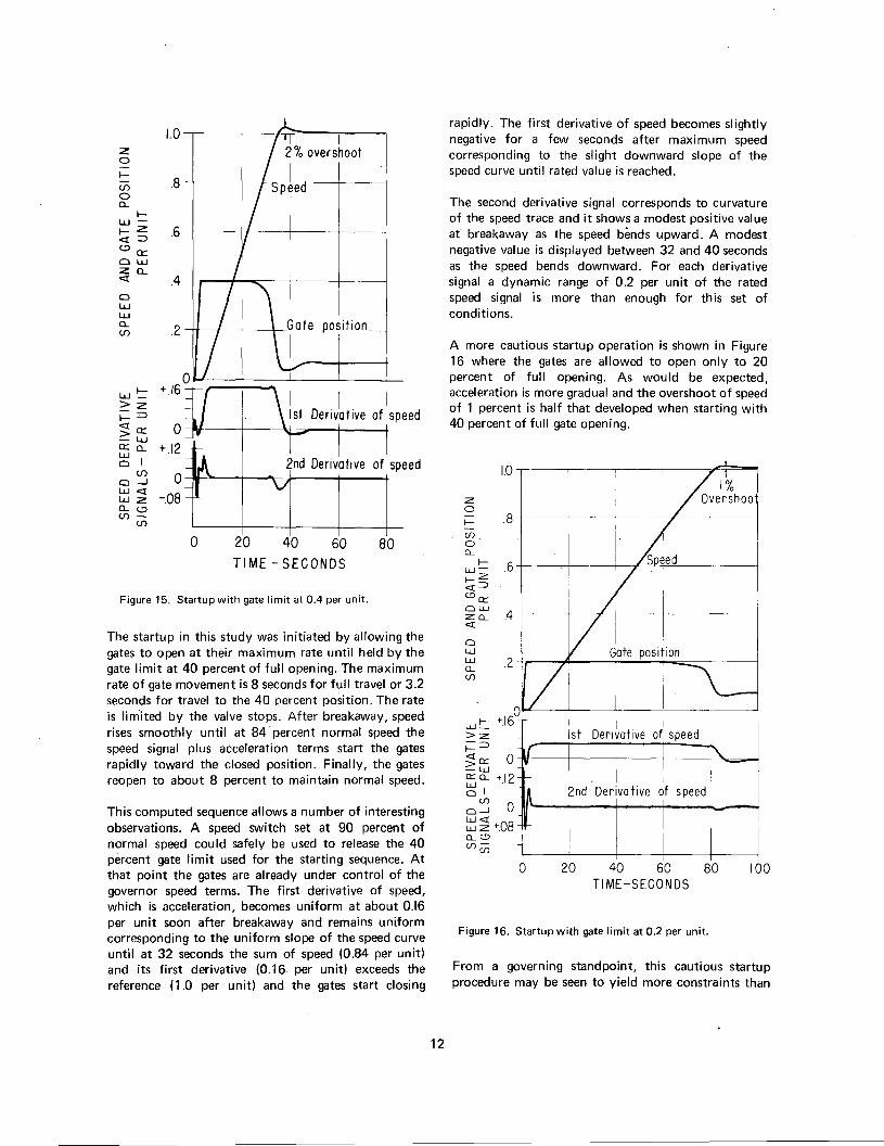
Startu p
Well controlled startup performance is especiallyimportant for peaking plants where the units may bestarted and stopped daily. Computed performanceduring startup in which the gates are allowed to opento 40 percent is shown in Figure 13. This wascomputed for a derivative governor of the type shownin Figure 3, servocontrol system of Figure 11 C, andbasic parameters as for Figure 4 (C and D).Performance is seen to be quite satisfactory withoutauxiliary control, overshoot of speed being only 2percent and reverting to stable speed for synchronizingin about 50 seconds.
11
1.0 IT 1Z 2 % over shoot0
II-.8(f) Speed
0a...
I-w -I-Z .6<:[=><..:)Q::0 wza...<:[ .40wwa...
.2(f)
z0f- .8(f)aa...
f- .6w-f-Z<:[=><..:)Q::ow
4za...<:[
0ww .2a...(f)
0w ~ +.16>zf==><:[Q:: 02:w~ a... +1201
o~ 0~ ~ -08a...<..:)(f) -(f)
0 20 40 60
TIME - SECONDS80
Figure 15. Startup with gate limit at 0.4 per unit.
The startup in this study was initiated by allowing thegates to open at their maximum rate until held by thegate limit at 40 percent of full opening. The maximumrate of gate movement is 8 seconds for full travel or 3.2seconds for travel to the 40 percent position. The rateis limited by the valve stops. After breakaway, speedrises smoothly until at 84 percent normal speed thespeed signal plus acceleration terms start the gatesrapidly toward the closed position. Finally, the gatesreopen to about 8 percent to maintain normal speed.
This computed sequence allows a number of interestingobservations. A speed switch set at 90 percent ofnormal speed could safely be used to release the 40percent gate limit used for the starting sequence. Atthat point the gates are already under control of thegovernor speed terms. The first derivative of speed,which is acceleration, becomes uniform at about 0.16per unit soon after breakaway and remains uniformcorresponding to the uniform slope of the speed curveuntil at 32 seconds the sum of speed (0.84 per unit)and its first derivative (0.16 per unit) exceeds thereference (1.0 per unit) and the gates start closing
rapidly. The first derivative of speed becomes slightlynegative for a few seconds after maximum speedcorresponding to the slight downward slope of thespeed curve until rated value is reached.
The second derivative signal corresponds to curvatureof the speed trace and it shows a modest positive valueat breakaway as the speed bEmds upward. A modestnegative value is displayed between 32 and 40 secondsas the speed bends downward. For each derivativesignal a dynamic range of 0.2 per unit of the ratedspeed signal is more than enough for this set ofconditions.
A more cautious startup operation is shown in Figure16 where the gates are allowed to open only to 20percent of full opening. As would be expected,acceleration is more gradual and the overshoot of speedof 1 percent is half that developed when starting with40 percent of full gate opening.
0w ~ +16>2:f==><:[~ 0:=:w~a... +.12
01(f)
0--1 0
~ ~ +08a...<..:)(f)(i)
10
H-1
I
of speed
0 20 40 60TIME-SECONDS
80 100
Figure 16. Startup with gate limit at 0.2 per unit.
From a governing standpoint, this cautious startupprocedure may be seen to yield more constraints than
12
benefits. The time for speed to become stable at setvalue is 100 seconds or twice as long as the timerequired when starting with 40 percent gate, yet thereduction of overshoot is of small consequence since alarger value could easily be tolerated. Furthermore, thespeed signals do not assume control of the gates untilthe speed reaches 94 percent of normal. If the 20percent gate limit for starting is to be released by aspeed switch, its setting must not be less than 95percent of normal, a more exacting setting than thatrequired when starting with 40 percent of full gateopening.
From these computations it is evident that governingneeds impose no restriction against the more rapidstarting proced'ure. Hence, final choice of procedurecan be made on the basis of mechanical, structural, orhydraulic conditions.
A few comment~ concerning parameters represented inthese computations are in order here. The governorcharacteristics, water hammer, and mechanical inertiawere all adequately represented in these runs by analogcomputer. The turbine torque versus speedchara{;teristic was represented as constant whereas inreality the torque of a Francis-type turbine is higher atreduced speed. More rigorous representation wouldshow the speed to rise a little more steeply at first,diminishing to the slopes shown near rated speed.However, since the correct value is represented forrated speed, the dynamic behavior near rated speed isaccurate and this is the region of prinicpal interesthere.
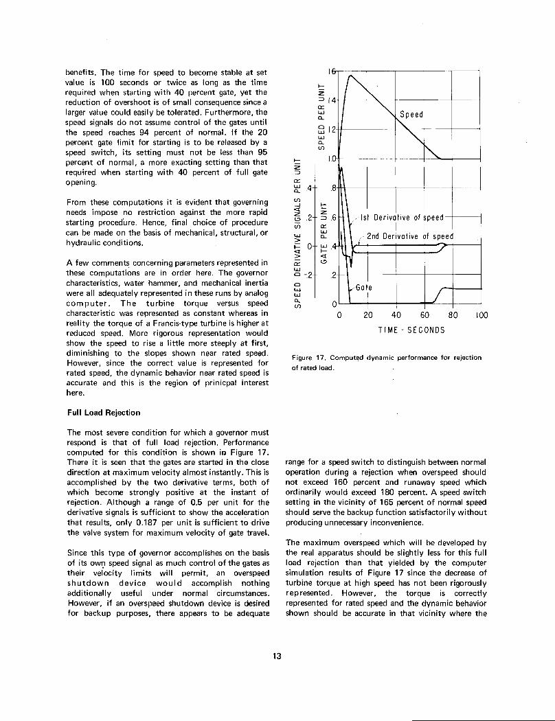
Full Load Rejection
The most severe condition for which a governor mustrespond is that of full load rejection. Performancecomputed for this condition is shown ir.l Figure 17.There it is seen that the gates are started in the closedirection at maximum velocity almost instantly. This isaccomplished by the two derivative terms, both ofwhich become strongly positive at the instant ofrejection. Although a range of 0.5 per unit for thederivative signals is sufficient to show the accelerationthat results, only 0.187 per unit is sufficient to drivethe valve system for maximum velocity of gate travel.
Since this type of governor accomplishes on the basisof its ow':! speed signal as much control of the gates astheir velocity limits will permit, an overspeedshutdown device would accomplish nothingadditionally useful under normal circumstances.However, if an overspeed shutdown device is desiredfor backup purposes, there appears to be adequate
t-Z~et:~ .4(f)
-I t-<[ -z Z19.2 ~.6(f) et:
lLJa...lLJ
>~0~.4> <[a: 19lLJa -.2
alLJlLJa...(f)
I.
t-z~1.4et:lLJa...
~ 1.2lLJa...(f)
.8
1st Derivative of speedi I I
- 2nd Derivative of speed
.2
Gate
00 20 40 60 80
TIME - SECONDS
roo
Figure 17. Computed dynamic performance for rejection
of rated load.
range for a speed switch to distinguish between normaloperation during a rejection when overs peed shouldnot exceed 160 percent and runaway speed whichordinarily would exceed 180 percent. A speed switchsetting in the vicinity of 165 percent of normal speedshould serve the backup function satisfactorily withoutproducing unnecessary inconvenience.
The maximum overs peed which will be developed bythe real apparatus should be slightly less for this fullload rejection than that yielded by the computersimulation results of Figure 17 since the decrease ofturbine torque at high speed has not been rigorouslyrepresented. However, the torque is correctlyrepresented for rated speed and the dynamic behaviorshown should be accurate in that vicinity where the
13

recovery is shown to be smooth. The gates reopen to aposition to maintain speed at no-load and the speedpresently becomes stable at the set value.
Partial Load Rejection
A partial load rejection can be considered a moresevere condition from a system load standpoint than afull load rejection since some of the load could becarried into overspeed, depending upon how the powersystem may be separated. At any rate, the performancefor partial load rejections shown in Figures 16A and16B are informative as to dynamic behavior at andbeyond the governing system's limit of linearity.
Figure 18A shows performance to be expectedfollowing rejection of the maximum amount of loadfor which the governor performance is reasonablylinear. This is a rejection of 30 percent of rated load. Itmay be noted that the distributing valve has just beendriven to its limit. However, by comparison withFigure 4C, it may be seen that the speed transient hasnot been appreciably distorted. The first derivativesignal developed was sufficient to drive the valve to itslimit setting before speed had risen appreciably. Thesecond derivative signal also contributes to promptaction of the valve although its initial spike was of tooshort duration to show.
Dynamic performance following rejection of 50percent load (from an initial load of 80 to 30 percent)is shown in Figure 18B. Here it may be noted that thevalve is held at its limit stop for 7 seconds. The turbinegates are driven at maximum velocity to the fullyclosed position where they remain for about 5 secondsuntil the speed and its derivatives call for reopening ofthe gates to a position to sustain normal speed. Becauseof limiting of velocity and of gate position, themaximum speed developed is more than a proportionalamount higher than that of Figure 18A, and recovery issomewhat slower. Yet behavior of speed is stablethrough the entire transient and it becomes optimumas soon as the governor can operate in its linear range.Derivative signals exceeding 0.25 per unit aredeveloped. A dynamic range of 0.4 per unit for thederivative terms should accommodate the practicalrange of parameter adjustments.
SYNCHRONIZING PERFORMANCE
A governor is seldom called upon to operate isolatedand at no-load for extensive periods, nevertheless,performance under this condition is important insofar
~1
.
2hJ,
_-:
.
10 II
I
~ II
(J)
10 -~
is.
8
ml
"
I
S; I '0 5-- ~Q
WI I~ ,
Z; 1'0 I-~
I
~~
z0~
'=2 ~3 Q
0:: WW >Q -J
<!>0 >
0::W0
=> +1Q
~2 ::' 00::w0-.1-gN
0 20 40 0
TIME - SECONDS BA
Figure 18. Computed performance for partial loadrejection.
A. Rejection of 30 percent load, the largest incrementfor linear response.
B. Rejection of 50 percent load, showing nonlinearperformance.
as it may influence the time required to synchronize agenerating unit to the system. In a powerplant forpeaking purposes, the units may be started and stoppeddaily and the rapidity with which they can besynchronized may become rather important. Followingemergencies such as load rejection from temporary lossof transmission lines, the rapidity with whichsynchronizing can be accomplished may become stillmore important.
The conditions for governing at no-load forsynchronizing differ appreciably from the conditionsdiscussed in preceding sections of this study. Thesignals for speed adjustment are small and there shouldbe no other appreciable perturbations. No influence ofvalve limits should be encountered as during severeconditions of load rejection or startup. However, theeffect of water starting time T w is only aboutone-tenth that effect at full load. Consequently,
14

Loaded oper-ation (A) 5.2 7.4 1.5 sec-
ondsSynchroniz-
ing (B) 3.5 1.5 0.5Synchroniz-
ing (C) 2.5 1.0 0.25
adjustments which yield best performance underloaded conditions would yield performance whichcould be appreciably improved upon for synchronizing.
Performance computed for the Coulee ThirdPower plant units under typical synchronizingconditions is shown in Figure 19. With governorparameters set for loaded operation, the response ofspeed to a speed change signal is shown by Curve A tobe quite stable but to require about 30 seconds toreach the final value. Appreciably better performancefor sychronizing can be achieved by the readjustmentsyielding Curve B which reaches a steady value in 9seconds. Still more rapid arrival at ultimate speed ispotentially possible with the more extensivereadjustments yielding Curve C which arrives at thefinal steady value in 5 seconds. For comparison, theadjustments for loaded operation and for bettersynchronizing, Curves Band C are tabulated following.
K11st deriv.
coefficient
K22nd deriv.
coefficient
T7pilot servo
integra-tion time
In practice, some influence from gate friction andminute amounts of backlash in the gate mechanismmay somewhat limit ability to accomplish ideal controlat the maximum rate. Adjustments in the vicinity ofCurve B are considered to be reasonable from apractical standpoint but the potentially useful range ofadjustment is nevertheless indicated by the tabulation.
CONCLUSIONS
1. Refinements of governing systems detailed hereinwill benefit speed control, area load control, and thecoordination of these two functions.
2. The refined governing systems can accomplish thedesired control with less confinement from the basicparameters of water starting time and mechanicalinertia that would be imposed by the heretoforeconventional governing systems. Some guide forproportioning of parameters has been offered.
0wwCL<f)
A
B
w>I-<I:-.JWa:
c
0 10 20 30
TIME - SECONDS
40
Figure 19. Response of speed to speed change signal under
conditions for synchronizing.
A. With governor adjustments for loaded operation,
K1 = 5.2, K2 = 7.4, T7 = 1.5 sec.
B. With governor parameters readjusted forsynchronizing, K1 = 3.5, K2 = 1.5, T 7 = 0.5 sec.
C. With governor parameters readjusted for most rapidsynchronizing, K1 = 2.5, K2 = 1.0, T 7 = 0.25 sec.
3. Governing of large hydraulic turbines can besubstantially improved by the addition of damping tothe servomotor control loop so that its gain can beincreased for faster response and better linearity.
APPLICABILITY
Results of this investigation are considered applicableto hydrogenerating installations in general. Althoughthe study was undertaken for benefit of the largerinstallations, expense of incorporating the refinementswould be small.
15

REFERENCES
1. H. M. Paynter, "The Analog in Governor Design I,"a Palimpsest on the Electronic Analog Art, p 228.
2. Patent No. 3,464,432, "Apparatus for StabilizingSpeed Control Action on Hydraulic Turbines," FerberR. Schleif.
3. M. Leum, "The Development and Field Experienceof a Transistor Electric Governor for Hydro Turbines,"IEEE Power Apparatus and Systems, Vol. 85, pp750-756, July 1966.
4. F. R. Schleif, L. W. Lloyd, Jr., R. W. World, and W.B. Gish, "A Swing Relay for the East-West Intertie,"IEEE Power Apparatus and Systems, Vol. 881, pp821-824, June 1969.
5. G. D. Friedlander, "Computer Controlled PowerSystems-Part II:' IEEE Spectrum, Vol. 2, pp 72-92,May 1965.
6. H. Schiott, "Optimum Setting of Water-TurbineGovernors," Transactions of the Society of InstrumentTechnology, pp 22-29, March 1960.
7. L. M. Hovey, "Optimum Adjustment of HydroGovernors on Manitoba Hydro System," AlEETransactions, Vol. 81, Part III, pp 581-587, December1962.
8. J. M. Undrill and J. L. Woodward, "NonlinearHydro Governing Model and Improved Calculation forDetermining Temporary Droop," IEEE PowerApparatus and Systems, Vol. 86, pp 443-452, April1967.
9. F. R. Schleif and R. R. Angell, "Governor Tests bySimulated Isolation of Hydraulic Turbine Units:' IEEEPower Apparatus and Systems Vol. 87, pp1,263-1 ,269, May 1968.
0aGG'ghphKK1K2KRKvLl',LNl',Nl',PSTT1 T3 T5T2 T4 T6T7Tg
Tm
TrTsTv1,Tv2TwVWR2
16
GLOSSAR Y OF SYMBOLS
Temporary droopPermanent droopGate positionPilot servomotor positionGravitational constantHorsepowerHeadComposite gainCoefficient of first derivativeCoefficient of second derivativeRestoring ratioValve constantLength of penstock sectionLoad control signalSpeedSpeed deviationLoad incrementLaplace operatorValve delayLead time constantsLag time constantsPilot servomotor integration timeGate response time constant to load
signalMechanical starting time =
N2WR2/1.6 x hp x 106Recovery time of temporary droopMain servomotor lag time constantResultant valve system delays
Water starting time = LL V/ghVelocity in penstock sectionInertia
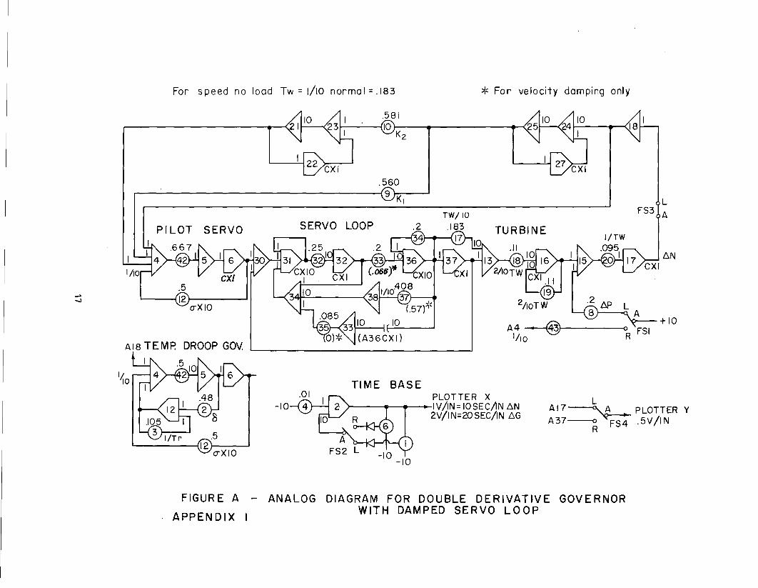
For speed no load Tw = 1/10 normal = .183 * For velocity damping only
18I
.5609
KI LFS3 A
I1/10
PI LOT SERVO SERVO LOOP TURBINE
~
-.J .26P L8 A
- ~- - + 10
A4~ FSI1/10 R
AI8 TEMP. DROOP GOv.
I
110TIME BASE
-10PLOTTER XIV/IN=IOSEC/!N AN
2V/1 N=20 SEC/IN AG
LAI7~PLOTTER YA37--o FS4 .5V/IN
R
FIGURE A - ANALOG DIAGRAM FOR DOUBLE DERIVAT~VE GOVERNOR
APPENDIX I WITH DAMPED SERVO LOOP

~
00
PilOT SERVO SERVO lOOP
IIto
.5/2 o-X 10
P43
18I
TURBINE .1119
10
(A36CXJ)A4 --@
~'For velocity damping only
L A
FS3
6N
+/0
FIGURE B - ANALOG DIAGRAM OF MODIFIED PARAllEL PATH PROPORTIONAl-
APPENDIX IINTEGRAL-DERIVATIVE GOVERNOR WITH DAMPED SERVO lOOP

+10
....
CD
FS3LA
+10 N
Servo loop and turbine(See Figure A , Appendix I,
Add IC to A37)
0RPilot servo position
Full gate = -IOVZero gate = OV
Max. gate velocity:t1.25V= 8 sec. travel
Normal speed = OVZero speed = -IOV
FIGURE C-ANALOG DIAGRAM FOR STUDY OF LARGE SIGNAL PERFORMANCEAPPENDIX I OF DOUBLE DERIVATIVE GOVERNOR-START UP,
LOAD REJECTION--ETC.


7-1750 (1-70)Bureau of Reclamation
CONVERSION FACTORS--BRITISH TO METRIC UNITS OF MEASUREMENT
The following conversion fa::tors adopted by the Bureau of Reclamatiol1 are those published by the American Society forTesting and Materials (ASTM Metric Practice Guide, E 380-68) except that additional factors (*) commonly used inthe Bureau have been added. Further discussion :>f definitions of quantities and units is given in the ASTM MetricPra::tice Guide.
The metric units and eonversion factors adopted by the ASTM are based on the "Intern'ltion'll 3-jstem of Units" (design'ltedSI for Systeme Intern'ltional d'Unites), fixed by the International Committee for Weights and Measures; this system isalso known as the Giorgi or MKSA (meter-kilogram (mass)-second-ampere) system. This system has been 'ldopted bythe Intern'ltional Organization for Standardization in ISO Recommendation R-31.
The metric technical unit of force is the kilogram~force; this is the force which, when applied to a body h'lving amass of 1 kg, gives it an acceleration of 9.80665 m/sec/sec, the standard acceleration of free fall toward the e'lrth'scenter for sea level at 45 deg latitude. The metric unit of force in SI units is the nei.\Tton (N), which is defined asthat force which, .when applied to a bo&y having a mass of 1 kg, gives it an acceleration of 1 m/sec/sec. These unitsmust be distinguished from the (inconstant) local weight of a body having 'l mass of 1 kg; that is, the weight of abody is that force with which a body is attracted to the earth and is equal to the mass of a body multiplied by theacceleration due to gravity. However, because it is general practice to use "pound" rather th'ln the technicallycorrect term "pound-force, "
the term "kilogram" (or derived mass unit) has been used in this guide instead of "kilogram-force" in expressing the conversion factors for forces. The newton unit of force will find increasing use, and isessential jn SI units.
Where approximate or n:>minal English units 'lre used to express a value or range of values, the comrerted metric unitsin parentheses are also approximate or nominal. Where precise English units are as ed, the converted metric unitsare expressed as equally significant values.
Multiply
Table I
QUANTITIES AND UNITS OF SPACE
By
LENGTH
To obtain
Mil. . . . . . . . . .Inches. . .Feet.
8 8 .8 8 . . . .
Yards. . . . . . . . . . .Miles(statute).. . .
. . . . . . . . . . . .
25.4 (exactly). .25.4 (exactly). . .2.54 (exactly)*. .
30.48 (exactly) . . . .0.3048 (exactly)*. .0.0003048 (exactly)*0.9144 (exactly) . .
1,609.344 (exactly)* . . .1. 609344 (exactly) .
AREA
. . Micron
. . Millimeters. Centimeters
Centimeters. Meters
. . . . Kilometers. Meters. . . Meters. Kilometers
Square ine hes .Squarefeet. . . . . .
Squareyards.Acres. . . . . . . .. . . . .Squaremiles. . . . . . . .
6.4516(exactly). . . .929.03*. . .
0.092903.O.836127.O.40469*. . . . . . .
4,046.9*. . . . . .O.0040469*. . . .2.58999. . . .
VOLUME
. . Square centimeters. Square centimeters
. . . . . Square meters. Square meters
. . Hectares. Square meters. Square kilometers
Square kllometers
Cubicinches. . . . . . . .Cubicfeet. . . . . . .Cubic yards. .
16.3871. . . .0.0283168. . . .O.764555. . . . .
CAPACITY
. . Cubiccentimeters. Cubicmeters. Cubicmeters'
29.5737. . . . . . . . . . Cubiccentimeters29.5729. . . . . . . . . . Milliliters0.473179. . . . . . . . . Cubicdecimeters0.473166. . Liters
946.358*. . . . . . . . . . Cubiccentimeters0.946331*. Liters
3,785.43* . . . . Cubiccentimeters3.78543.. . . . . . . . . Cubicdecimeters3.78533.. . . . . LitersO.00378543*.. . . . Cubicmeters4.54609 . . . . . . . . . Cubicdecimeters4.54596 . . . . . . Liters
28.3160. . . . . . . . . . Liters764.55* . . . . . . . Liters
. . .. 1,233.5*. . . . . . . . . . . Cubicmeters. . .1,233,500*
""""'"Liters
Fluid ounces (U.S.) .
Liquid pints (U. S. )
Quarts (U.S.) .
Gallons (U.S.). . . .
Gallons(U.K.) . . . . . .. . . . . .
Cubic feet. .Cubic yards. .Acre-feet. .

Table II
QUANTITIES AND UNITS OF MECHANICS
Multlplv To obtainBy
MASS
Grains (1/7,000 lb) . . . . . . . ., 64.7g8g1(exactly). . Mil1!gramsTroyounces(480""alns).. . 31.1035.. . . . . . . . . . GramsOunces(avdp).. . . . . . 28.34g5. . . . . . . . . . . Grams~~~;tdfo~~v1~:00oib): : : : : : : :: gO~:i~~5~2~7.(e:'"'~tl.y):
. . . .~~~::~
. ., O.007185.. . . . . . . . . MetrIctonsLonqtons(2,240lb):: . . . . . . .1,016.05. . . . . . . . KlloqramsFORCE/AREA
Poundsper square inch. . . . . . .. . . . . . .
Poundsper squarefoot. . . . . . .. . . . . . .
Ounces per cubic inch. . . .Pounds per cubic foot. . . .
Tons (lonq) per cubic w.rd: .
Ounces per gallon (U.S.) . . . . . .Ounces per gallon (U.K.) . . . . . .Pounds per gallon (U.S.) . . . . . .Pounds per qalion (U.K.) . . . . . .
O.070307. . . . . . . . . . Kilograms per square centimeter0.889476. . . . . Newtonsper square centimeter4. 88243 . . . . . Kilograms per square meter
47.8803. . . . . . . . . . . Newtonsper square meter
MASS/VOLUME(DENSITY)
1. 72999 . . Grams per cubic centimeter16.0185 . Kilograms per cubIc meter0.0160185 . . . . . Grams per cubic centimeter1. 32894 ,. Grams per cubic centimeter
MASS/CAPACITY
7.48gs. . . . . . Gramsperliter6.2362. . . . . . Gramsperliterng. 82g. . . . . . . Gramsperlitergg.77g. . . . . . . . . . . Gramsperliter
BENDING MOMENT OR TORQUE
Inch-pounds:: : : : : : :
. . .. ~:~~~~~1,;106:Foot-pounds:
: : : : : : :. . .. ~:~~~~~5,;107:
Foot-poundsperInch. . . . . . .. 5.4431....Ounce-Inches.. . . . . . . 72.008. . . . . . . . .
VELOCITY
. . . Meter...ldloqrams. . Centimeter-dynes
. . . Meter-k1loqrams
. . . Centimeter-dynes. . Centimeter-ldloqrams per centimeter. . Gram-centimeters
Feet per second. .. . . . . . . . . .Feetperyear.. . . . . . . . . . .M1lesperhour .. . . . . .
30.48 (exactly). . . . . . . . Centimeters per second0.3048 (exactly)* . . . . . . Meters per secondO.g65873 x 10-6* . . CentImeters per second1. 60g344 (exactl ). . . . . . .Kllometers per hour0.44704 exactl . Meters r second
ACCELERATION*
0.3048* . . . . . . . . . . Meters per second2FLOW
Feet oor second2 . . . . . . . . . .
Cubic feet per second (second-feet). . . . , . . . . . . . . . .Cubicfeetper minute. . . . . . . .Gallons(U.S.) per minute. . . . . .
0.028317* . . . . . . . . . CubIcmeters per second0.471g , Liters per second0.0630g . . . . . LIters per second
FORCE*
. . . . . . . . . . . . . . . 0.4535g2*. . . . . . . . . Kilogramsu:~rx 10-5* : : : : : : : g~~ns
Pounds.. . . . . . . . . . . . . .. . . . . . . . . . . . . . .
Multiply To obtainI
Bv
WORK AND ENERGY'
BrItIsh thermal units (Btu).
Btu per pound. . . .Foot-counds . . .
. O.252* . KilogramcalorIes. . 1,055.06... . . . . . . . . Joules2.326 (exactly) . . . Joulesper gram1.35582*.. . . . Joules
POWERHorsepower.. . . . . . .Btuperhour. . . . . . . . . . . .Foot-poundsDer second. . . . . . .
745.700. . . , . . . WattsO.2g3071.. . .,. . . . . . Watts1.35582, . . . . . . . . . Watts
HEAT TRANSFER
Btu In. /hr ft2 deg F (1<:,thermal conductIvity) . . . . . . .
Btu ft/hr ft2 dej F . . : : :B;%~~~~~j . (~,.t~er.~.
Deg F hr ft2/Bt~ cit: the;mi..1'. . . .
resistance). . . . . . . . . . . .Btu/lb deg F (c, heat capacity). . . .
~~J~ ~~~e;mi..1'dlffusl;'liy).
6:mo:. . . . . . ~~:;i~/~':Jedeg C
1.4880*.. . . . . . Kgcalm/hrm'ldegC
O.568 . Mil1lwatts/cw2 deg C4, 882 Kg caI/hr m deg C
1. 761 Deg C cm2/mIlllwattUgg~ Y~/eg C
d C0.2581 ., . . . C
a 2~ram eg
O.Og2g0*. MW/h:ec
WATERVAPORTRANSMISSION
Grains/hr ft2 (water vaportransmissIon).. . . . .
Perms (permeance). .." .
Perm-Inches (permeabll1tv) .
Multlplv
Cubic feet per square foot perday (seepage) . . . . . . . . . . .
Pound-seconds per square foot(vIscosity) . . . . . . . . . . . .
Square feet per second (viscosity). . .Fahrenheit degrees (change)*. . . . .Voltspermil. . . . . . . . . . . .L~~~s~er. s:~~ ~o~t ~fo~t:Ohm-cIrcular mils per foot.M1llicuries per cubic foot. .M1lliamps per square foot.Gallons per square yard. . .Pounds cer inch. . . . . . .
16.7 .."..0.65g.1.67 . . . . . .
Grams/24 hr m2. Metric perms. Metric oerm-centimeters
Table III
OTHER QUANTITIES AND UNITS
Bv To obtaIn
304.8*. . . . . . . . . . .4.8824*. . . . .0.Og2oo3*.. . .5/g exactly. . .0.03g37,.. . . .
Liters per square meter per day
KUoqram second per square meterSquare meters per secondCelsIus or Kelvin degrees (change)*KUovolts per millImeter
10.764.. . . . . . . . . .0.001662. . . . . . . . .35.3147*. . . . .10.763g*, . . . . . . . .4.52721g*. . . . . . . .O.17858*.. . . .
Lumens per square meterOhm-square millimeters per meterM1ll1curies per cubic meterMill1amps per square meterLiters per square meterKlloarams oer centimeter
GPO 834 - 578

I. . . . . . I . I . . . . . . . . . . . . . . . . . . . . . . . . . . . . . . . . . . . . . . . . . . . . . . . . . . . . . . . . . . . . . . . . . . . . . . . . . . . . . . . . . . . . . . .
ABSTRACT
In considering appropriate parameters for large hydropower generating units, the choice ofcontrol characteristics to satisfy power system needs strongly influences the economics ofdesign. Parameters fundamental to control characteristics which can be determined by thedesigners are mechanical inertia or flywheel effect and penstock time constant. To aid thedesigner with a basis for the most economical combinations of parameters to satisfy the powersystem needs, a study analyzing the requirements and their interrelation was made. Results ofthe study are given. The influence of the governing system and refinements with several newfeatures for bette"r speed control were investigated toward improved coordination between unitspeed control and area load control. A guide for proportioning of parameters is proposed.
.
.
.
.......
In concontroldesign.designEdesignesystemthe stufeaturespeed c
. . . . . .' . . . . . . . . . . . . . . . . . . . . . . . . . . . . . . . . . . . . . . . . . . . . . . . . . . . . . . . . . . . . . . . . . . . . . . . . . . . . . . .:
. .
ABSTRACT
In considering appropriate parameters for large hydropower generating units, the choice ofcontrol characteristics to satisfy power system needs strongly influences the economics ofdesign. Parameters fundamental to control characteristics which can be determined by thedesigners are mechanical inertia or flywheel effect and penstock time constant. To aid thedesigner with a basis for the most economical combinations of parameters to satisfy the powersystem needs, a study analyzing the requirements and their interrelation was made. Results ofthe study are given. The influence of the governing system and refinements with several newfeatures for better speed control were investigated toward improved coordination between unitspeed control and area load control. A guide for proportioning of parameters is proposed.