gorge 2nd tunnel - seattle
TRANSCRIPT

Gorge 2nd Tunnel
Preliminary Geologic Assessment April 24, 2009
Seattle City Light
Prepared by:
Aspect Consulting, LLC 401 Second Avenue S, Suite 201
Seattle, WA 98104
Jacobs Associates 1109 First Avenue Suite 501
Seattle, WA 98101

Jacobs Associates -ii- Rev. No. 0/April 24, 2009
Distribution To: John Owen Seattle City Light From: Gregg Davidson Jacobs Associates Prepared By: Susan L. Bednarz, RG Jacobs Associates Dave McCormack, LEG Aspect Consulting Annaliese Eipert Aspect Consulting Reviewed By: Gregg Davidson Jacobs Associates

Jacobs Associates -iii- Rev. No. 0/April 24, 2009
Table of Contents
1 Introduction ....................................................................................................................... 1
2 Project and Site Description .............................................................................................. 2
3 Regional Geology .............................................................................................................. 3
4 Site Geology ...................................................................................................................... 4 4.1 Existing Data Sources ......................................................................................................... 4
4.2 Bedrock ............................................................................................................................... 5
4.3 Geologic Structures............................................................................................................. 7
4.4 Groundwater ..................................................................................................................... 10
4.5 Condition of Existing Excavations ..................................................................................... 11
5 Conclusions and Recommendations for Further Study ................................................... 12
6 References ...................................................................................................................... 14
Revision Log ............................................................................................................................... 15
Appendix A. Additional Data ....................................................................................................... 16
Appendix B. Preliminary Geologic Plan and Profile .................................................................... 17

Jacobs Associates -iv- Rev. No. 0/April 24, 2009
List of Tables
Table 1. Orientation of Foliation .................................................................................................... 7
Table 2. Orientations of Lineaments and Potential Faults ............................................................ 9

Gorge 2nd Tunnel Preliminary Geologic Assessment
Jacobs Associates -1- Rev. No. 0/April 24, 2009
1 Introduction This Preliminary Geologic Assessment Report presents a summary of existing geologic and geotechnical data relevant to the proposed Gorge 2nd Tunnel (G2T) project. The primary goal of this data compilation is to identify any existing information that may be used in coordination with data obtained from our planned geologic explorations and analysis to characterize geologic conditions for the design and construction of the G2T project. This task also identifies potential sources of additional geologic data and provides recommendations for additional analyses. The following sections of this report describe information regarding the geology of the project site, the data sources referenced, bedrock characteristics and quality, geologic structures, groundwater conditions, conditions of existing excavations, and conclusions and recommendations regarding additional study. The observations and ideas conveyed in this report represent an initial review of presently available data. This information will be used in the tunnel diameter optimization tasks and in planning the field investigation activities.

Gorge 2nd Tunnel Preliminary Geologic Assessment
Jacobs Associates -2- Rev. No. 0/April 24, 2009
2 Project and Site Description The Gorge Powerhouse facilities are located near Newhalem in the Cascade Range of Washington State, about 90 miles northeast of Seattle. The Gorge Powerhouse and the existing 11,000-foot-long, 20.5-foot-internal-diameter, concrete-lined tunnel (G1T) were built by the Seattle City Light (SCL) public utility following approval of hydroelectric facilities on the Skagit River by the federal government in 1918. The facilities at Gorge Dam began providing power to Seattle in 1924. The original tunnel, still in service to this day, conveyed water to three turbine units. In 1949 SCL was authorized to expand the Powerhouse, build the Gorge High Dam, and install a turbine unit. These additions increased overall output but decreased efficiency by creating more friction between the tunnel walls and now faster-moving water. For nearly 20 years, SCL has been considering a second parallel power tunnel as a way to optimize the Gorge Powerhouse facilities. With an interest in renewable opportunities from existing hydro facilities, SCL identified the G2T project to help the utility meet the requirements of I-937. The Gorge 2nd Tunnel will be a largely unlined, 14-to-8-foot-diameter tunnel bored between the Gorge Powerhouse and the intake at Gorge Dam. It will parallel the existing tunnel, increasing generating efficiency by reducing head loss. This will allow SCL to better optimize the powerhouse without altering flows to the Skagit River. This is important for maintaining Seattle’s long standing stewardship of the Skagit River fishery. The initial phase of the Gorge 2nd Tunnel project includes tunnel diameter optimization and layout studies, hydraulic transient analysis, site layout evaluations, water quality studies, a water management plan, and cost estimates for the recommended tunnel and connection configurations. It also includes a potential inspection of the existing tunnel, mandated by the Federal Energy Regulatory Commission. This phase will be followed, in the summer of 2009, by preliminary geologic investigations, which will produce a geotechnical data report and geotechnical baseline report strategy memorandum.

Gorge 2nd Tunnel Preliminary Geologic Assessment
Jacobs Associates -3- Rev. No. 0/April 24, 2009
3 Regional Geology The project area is located in the North Cascades range of north-central Washington State. The geology of the North Cascades is a tectonically complex series of geologic terranes that have accreted over the last 400 million years to form the landmass of western North America. The geologic terranes that are now joined together include remnants of volcanic island arcs, deep ocean sediments, ocean floor basalt, old continental crust, submarine fans, and subcrustal mantle. The processes of accretion, burial, exhumation, and volcanism have resulted in rocks that are strongly folded, faulted, and metamorphosed. Five major events are recorded in North Cascades geology (Tabor et al., 2003). These events are: (1) the pre-mid-Cretaceous assembly of Mesozoic and Paleozoic terranes with various paleogeographic origins and structural/metamorphic histories; (2) mid-Cretaceous to late-Cretaceous thickening and metamorphism by thrusting and pluton accumulation; (3) Eocene strike-slip and extensional faulting, basin development, and continued metamorphism and plutonism; (4) development of the Cascade magmatic arc in Oligocene to Holocene time; and (5) Quaternary glacial erosion, drainage derangement, and deposition of glacially derived sediments. The terranes of the North Cascades can be tectonically divided into three sections separated by two major strike-slip fault zones, the Straight Creek fault, and the Ross Lake fault zone. Rocks to the west of the Straight Creek fault and east of the Ross Lake fault zone are generally less metamorphosed than those rocks that lie between the two faults and within the “metamorphic core.” These metamorphic core rocks have been uplifted approximately 7 to 11 miles relative to the rocks on either side. The town of Newhalem and the Gorge Power Station are located in the metamorphic core of the North Cascades, the zone of deformation between two major fault zones. The bedrock at the project site has been thoroughly metamorphosed and exposed to various episodes of faulting and shearing, which has created zones of weakness that must be considered throughout the development of the project. Geology specific to the project site is discussed in more detail in the following sections.

Gorge 2nd Tunnel Preliminary Geologic Assessment
Jacobs Associates -4- Rev. No. 0/April 24, 2009
4 Site Geology 4.1 Existing Data Sources Preliminary classification of site geology is based on a review of existing data, as well as preliminary observations conducted thus far for the current study. Referenced sources are summarized below, and listed individually in Section 6. of this report. Several additional data sources have been identified during the course of this compilation. These additional sources are briefly described in Appendix A. A Preliminary Geologic Plan and Profile, based on currently available information, is presented in Appendix B. 4.1.1 Outside Data All readily available sources were reviewed for the purposes of this data summary report. Sources vary widely in content, style, quality, and value of information, and date from three main phases of Gorge facilities activity:
• Initial Gorge Powerhouse, timber crib dam, and G1T construction (1918 to 1923) • Midcentury Gorge facility improvements, including construction of the Gorge High Dam, the
Gorge Powerhouse Extension, Penstock #24, and subsequent inspections of the dam and tunnel (1948 to 1990)
• Recent efforts to characterize G2T feasibility and cost (~2007 to 2009)
In addition, Light Detection and Ranging (LiDAR) topographic mapping (2006) was also identified as an available data source. Early records relate to Gorge power station and tunnel construction, which occurred from approximately 1918 to 1923. These include weekly progress reports from January to July of 1922 on the “Skagit River Power Development” (City of Seattle, 1922) and detailed borehole logs and maps for the original Gorge Dam (SCL, 1918–1923). However, no detailed construction plans or as-built plans or geologic conditions encountered during tunneling were available for review. Midcentury sources include plans, detailed borehole logs, maps and cross sections, and core photographs from 1947 to 1948 (SCL, 1947–48) in preparation for the Gorge Powerhouse Extension. A record of construction for the Gorge Powerhouse Extension was also examined (SCL, 1951), which describes construction activity from 1948 to 1951 in a comprehensive narrative style. An incomplete Geologic Report on the Gorge High Dam from 1954 (SCL, 1954a) contains the original 1918 to 1923 Gorge Dam borehole logs and maps; additional borehole logs (including notes on fracturing and water loss), cross sections, and exploration maps; a useful description of bedrock weathering patterns, and a quantitative chart representing percentage of core loss from various exploration locations from 1953 to 1954. Also referenced were a 1954 inspection of the Gorge High Dam Site (SCL, 1954b) and a 1963 inspection of the Gorge Plant Power Tunnel (SLC, 1963), which provide some information on bedrock, geologic structures, and groundwater seepage into the existing tunnel. Tunnel inspection reports from 1971, 1979, 1986, and 1990 were also reviewed but did not include any geologic information. Of the recent sources, perhaps most pertinent from a geologic characterization perspective is the Conceptual Cost Estimate Study completed by Hatch Mott MacDonald (HMM) in February 2007 (HMM,

Gorge 2nd Tunnel Preliminary Geologic Assessment
Jacobs Associates -5- Rev. No. 0/April 24, 2009
2007), which contains preliminary interpretations of tunnel alignment geology, mineralogy, rock quality and strength, and groundwater inflows as they relate to the proposed G2T. The G2T site area has been aerially surveyed by LiDAR. DEM data were downloaded and used to develop lightshade and topographic contour maps of the project area. The preliminary LiDAR lineament analysis is discussed in Section 4.3. 4.1.2 Reconnaissance for this Study Initial reconnaissance for the study began on July 17, 2008, with a visit to the Devil’s Elbow Adit. The visit was conducted by Jacobs Associates (JA) and Aspect Consulting, LLC (Aspect). The July 17, 2008, visit is detailed in a Site Visit Log by Jacobs Associates (JA, 2008). Work since then has consisted of literature research and review and another site reconnaissance visit on March 10, 2009 (JA, March 2009). Field notes from these 2008 and 2009 reconnaissance visits were reviewed and incorporated into this data summary. 4.2 Bedrock Bedrock along the tunnel alignment is expected to consist primarily of orthogneiss, a foliated (mineralogically banded), metamorphosed igneous rock of granitic composition that crops out mostly between Newhalem and Ross Lake, to the east. Orthogneiss consists primarily of the minerals plagioclase feldspar, quartz, biotite, and hornblende. Specifically, the orthogneiss in the alignment area is a member of the Middle Eocene to Late Cretaceous-age Skagit Gneiss Complex of the North Cascades, and consists of primarily medium-to-coarse-grained (1 mm to 20 mm long crystals) foliated hornblende-biotite tonalite gneiss and quartz diorite gneiss. A pegmatite (very coarse-grained intrusive igneous rock) with greater than 20 mm long crystals, containing a mineral assemblage similar to the orthogneiss but with a much higher feldspar and quartz content (JA, 2008), is also present in the form of large concordant and discordant intrusions through the bedrock. Based on observations within the Devil’s Elbow Adit, these intrusions can be greater than 100 feet in width (HMM, 2007). According to the HMM 2007 study, the overall rock mass (orthogneiss and pegmatite) may be made up of to 25% quartz, a hard mineral, and may contain approximately 2 to 3% garnet. As based on HMM’s October 12, 2006, field observations from the areas surrounding the intake, surge shaft, Gorge Powerhouse, and potential G2T portal locations, and its subsequent petrographic analysis of samples collected during this visit (HMM 2007), no erodible minerals are expected within the excavation. Erodible minerals are relevant to tunnel excavation and construction because of their capacity to weaken the rock and be easily removed by water. 4.2.1 Weathering The HMM 2007 report indicates that bedrock in the vicinity of the proposed tunnel alignment is generally fresh and unweathered, but is moderately to highly weathered in fault/shear zones. The JA 2008 reconnaissance supports these observations. The 1954 geologic report for the Gorge High Dam (SCL, 1954a) indicates the presence of highly weathered zones of bedrock around joints and faults, and emphasizes the presence of unevenly distributed iron sulfides, which can lead to accelerated bedrock weathering, in the rocks at Gorge High Dam.

Gorge 2nd Tunnel Preliminary Geologic Assessment
Jacobs Associates -6- Rev. No. 0/April 24, 2009
The Gorge High Dam geologic report (SCL, 1954a) cites the following common weathering pattern in Gorge High Dam rocks:
At and near the surface the iron sulfides are oxidized to hydrous iron oxides and the rock shows maximum weathering out from the joints. At greater depth, some of the iron sulfides are oxidized to the hydrous iron oxides and some remain fresh and unaltered. In and below this lower zone of partial oxidation is a zone of sulfate precipitation, commonly in the form of white gypsum or selenite (calcium sulfate) and less commonly as yellow melanterite (iron sulfate). Weathering is absent or minor in this sulfate zone. The depths of weathering vary widely and may be determined for each hole by a study of the individual geologic logs.
The final sentence of the quoted material seems to indicate potentially high spatial variability with regards to the weathering patterns of these rocks. 4.2.2 Rock Strength Rock strength testing was conducted as part of the HMM 2007 report. Rock cores were extracted from block samples collected during a site visit on October 12, 2006, by representatives from HMM, the SCL Seattle Office, and the SCL Gorge Power Station. Eight uniaxial compressive strength (UCS) tests were completed to ASTM 2938-95 at the Department of Mining Engineering, Rock Testing Laboratory of British Columbia, in Vancouver, Canada. Rock strengths range from 7,800 psi to 19,500 psi. Two samples that were deemed to have failed prematurely along weak fractures were filtered out of the overall results. Discounting these two values, average bedrock strength value was calculated to be approximately 18,100 psi. The Gorge High Dam geologic report (SCL 1954a) report contains a quantitative chart representing the percentage of core loss from 23 diamond core borehole exploration locations. Of the 23 boreholes, 17 were labeled competent, 5 were labeled subcompetent, and one transitioned from relatively competent to subcompetent. Competency descriptors were not defined. Up to three different core diameters were obtained for each boring, with a smaller casing being driven inside a larger one when the original pipe was restricted due to depth, tightness, or bending. Percentage of core loss for each borehole ranged from approximately 0.25% to 10%, and averaged approximately 4.25%. It should be noted that faults encountered during drilling conducted for the Gorge High Dam do not necessarily cross the proposed G2T alignment. 4.2.3 Mineralogy Petrographic analysis was conducted in order to determine mineralogical composition of bedrock. Special emphasis was placed on observations of factors that could affect the TBM process, such as the presence of hard minerals (quartz, epidote, garnet, etc.), minerals susceptible to erosion, and degree of alteration, which could indicate weakened bedrock. HMM conducted petrographic thin section analyses on six samples during their October 2006 site visit. The results indicate a primary composition of quartz, plagioclase feldspar, hornblende, and biotite (HMM, 2007). Hard minerals relevant to tunnel excavation are present in the form of significant quartz content (10 to 25%), and a minor amount (2 to 8%) of garnet. No indications of sulfides were observed in the samples. Minor bedrock alteration was observed, with some sericite and a very limited amount of microfracturing present.
Gorge 2nd Tunnel Preliminary Geologic Assessment
Jacobs Associates -7- Rev. No. 0/April 24, 2009
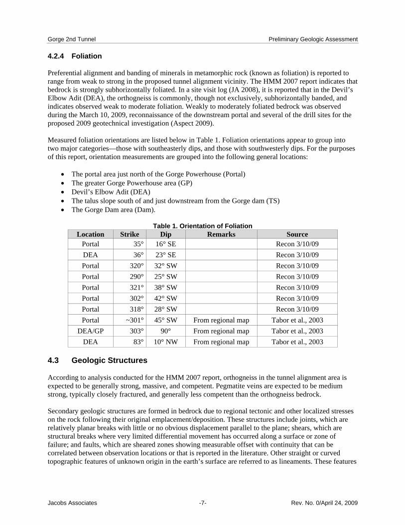
4.2.4 Foliation Preferential alignment and banding of minerals in metamorphic rock (known as foliation) is reported to range from weak to strong in the proposed tunnel alignment vicinity. The HMM 2007 report indicates that bedrock is strongly subhorizontally foliated. In a site visit log (JA 2008), it is reported that in the Devil’s Elbow Adit (DEA), the orthogneiss is commonly, though not exclusively, subhorizontally banded, and indicates observed weak to moderate foliation. Weakly to moderately foliated bedrock was observed during the March 10, 2009, reconnaissance of the downstream portal and several of the drill sites for the proposed 2009 geotechnical investigation (Aspect 2009). Measured foliation orientations are listed below in Table 1. Foliation orientations appear to group into two major categories—those with southeasterly dips, and those with southwesterly dips. For the purposes of this report, orientation measurements are grouped into the following general locations:
• The portal area just north of the Gorge Powerhouse (Portal) • The greater Gorge Powerhouse area (GP) • Devil’s Elbow Adit (DEA) • The talus slope south of and just downstream from the Gorge dam (TS) • The Gorge Dam area (Dam).
Table 1. Orientation of Foliation
Location Strike Dip Remarks Source Portal 35° 16° SE Recon 3/10/09 DEA 36° 23° SE Recon 3/10/09 Portal 320° 32° SW Recon 3/10/09 Portal 290° 25° SW Recon 3/10/09 Portal 321° 38° SW Recon 3/10/09 Portal 302° 42° SW Recon 3/10/09 Portal 318° 28° SW Recon 3/10/09 Portal ~301° 45° SW From regional map Tabor et al., 2003
DEA/GP 303° 90° From regional map Tabor et al., 2003 DEA 83° 10° NW From regional map Tabor et al., 2003
4.3 Geologic Structures According to analysis conducted for the HMM 2007 report, orthogneiss in the tunnel alignment area is expected to be generally strong, massive, and competent. Pegmatite veins are expected to be medium strong, typically closely fractured, and generally less competent than the orthogneiss bedrock. Secondary geologic structures are formed in bedrock due to regional tectonic and other localized stresses on the rock following their original emplacement/deposition. These structures include joints, which are relatively planar breaks with little or no obvious displacement parallel to the plane; shears, which are structural breaks where very limited differential movement has occurred along a surface or zone of failure; and faults, which are sheared zones showing measurable offset with continuity that can be correlated between observation locations or that is reported in the literature. Other straight or curved topographic features of unknown origin in the earth’s surface are referred to as lineaments. These features
Gorge 2nd Tunnel Preliminary Geologic Assessment
Jacobs Associates -8- Rev. No. 0/April 24, 2009
can often be identified from aerial photographs, topographic maps, or LiDAR imagery. Lineaments most frequently result from jointing, faulting, volcanism, or other tectonically controlled phenomena. Many geologic structures have been observed or previously mapped in the project area. Numerous potential lineaments also are visible on topographic maps and aerial photos. While the majority of measurements of geologic structure orientations were taken during the geologic reconnaissance on March 10, 2009, readily accessible orientation measurements from the Gorge literature review as well as from the regional geologic literature have also been compiled. A summary of observations and measurements is presented below, along with a listing of the currently known measurements of their orientations. 4.3.1 LiDAR Lineament Analysis Aerial LiDAR survey data for the project area were acquired by the U.S. Geological Survey in 2006. The LiDAR survey extended along the Skagit River valley as far east as Ross Dam. These LiDAR data are available from the U.S. Geological Survey (U.S. Geological Survey, 2006) as sets containing individual latitude, longitude, and elevation points (termed XYZ data) measured at approximately every 5 feet on the ground surface. In comparison, topographic survey maps available before LiDAR surveys were performed have a point density of one for every ∼30 feet, so discrimination of small and subtle topographic changes is potentially much greater with LiDAR. Point XYZ returns from the survey include tree top and vegetation canopy as well as the last return, which is considered to be from the “bare earth.” These bare earth data are then used to generate a digital elevation model (DEM) of the ground surface, which can then be used to generate topographic contour maps, light-shaded (artificially illuminated) relief maps, and other map products. Lineament analysis will be conducted in conjunction with field mapping using these detailed topographic maps. LiDAR map generation consists of plotting the regional and site-specific area of interest using artificial illumination angles from four compass quadrants in addition to a set generated by combining light from the northwest, north, and northeast into a north composite projection. Lineaments are then plotted on individual maps. Some lineaments show more clearly on a specific lightshade projection angle; therefore, each quadrant lightshade map is analyzed separately and the lineaments from each are combined on the north composite image. LiDAR lineaments are then studied in the field, where access permits. Lineaments that are confirmed to be faults, shear zones, or joints are directly observed to collect orientation, width, infilling, weathering and other data that are relevant to analysis of structures in the rock, with particular emphasis on structures that may be intercepted during tunneling and may have impacts on seepage and excavation stability. LiDAR maps of the site area have been developed using the 2006 U.S. Geological Survey data. Preliminary lineament analysis has been conducted in conjunction with field mapping. This information will be evaluated and incorporated in project geological assessment documents. 4.3.2 Joints According to observations made JA 2008 reconnaissance site visit, the tunnel alignment area rock mass is generally very widely jointed, with joint spacing ranging from 3 to 10 feet, with zones of extremely wide joint spacing of greater than10 feet. Moderate jointing is expected at the site of the new downstream portal, located in a hillside to the north of the Powerhouse. The joints are generally tight, unstained, and unmineralized, with the exception of shears and fault-related sheared zones. Jointing commonly follows

Gorge 2nd Tunnel Preliminary Geologic Assessment
Jacobs Associates -9- Rev. No. 0/April 24, 2009
foliation planes, along with three or more other regional trends. The orientation of these major jointing patterns controls the shape of many of the cliffs and outcrops. A list of measured joint orientations can be found in Table 2 below. Core photographs associated with the Gorge Powerhouse extension (SCL, 1947) indicate that joint spacing in this area is quite variable. The photographs display core lengths of tens of feet with inch to sub-inch joint spacing, followed by core lengths of tens of feet with no apparent joints. This variability in joint spacing is likely attributable to the potential for highly fractured zones and sub-surface weathering associated with faults.
Table 2. Orientations of Lineaments and Potential Faults Location Strike Dip Continuity Remarks Source
TS 20° 90° 1,000s ft 100 ft wide zone consisting of two sheared zones, 20 ft each (as seen from Hwy 20)
Recon 3/10/09
Dam ~90° ~90° Interpreted from written description
SCL,1954b
Dam ~315° 18° NE
Strike roughly estimated from written description.
SCL,1954b
GP N/A ~0° 100s ft Interpreted from written description
SCL,1951
GP 32° ~90° Miles Inferred Ladder Creek Fault Tabor et al., 2003 GP 355° 1,000s+ ft Potential lineament Tabor et al., 2003
DEA 2° 1,000s+ ft Potential lineament Tabor et al., 2003 Dam 30° 1,000s+ ft Potential lineament Tabor et al., 2003 Dam 311° Possible fault/lineament Recon—this study Dam 34° Possible fault/lineament Recon—this study Dam 0° 100s ft Potential fault/ lineament Recon—this study
GP/DEA 0° 100s ft Lineament Several parallel lineaments
identified this study DEA 75° 70 NE Observed sheared zone Recon—this study Portal 315° 62°
SW 30 ft+ 2 ft wide shear zone, 1 in.
spacing of individual sheared joints
Recon 3/10/09
4.3.3 Faults Several faults have been observed in the project area. Additional large-scale lineaments of unknown origin have been identified over the course of initial stages of the current study, as well as in the HMM, 2007 report, based on topography, aerial photos, and geologic maps. Approximately nine fault-related sheared zones were observed within the Devil’s Elbow Adit on July 17, 2008 (JA, 2008). Sheared zones ranged in thickness from less than one foot to about 10 feet thick. Preliminary potential faults and lineaments are generally perpendicular or oblique to the G2T alignment, as indicated on the Preliminary Geologic Plan and Profile in Appendix B. Notes from the Gorge Powerhouse Extension Record of Construction from 1948 to 1951(SCL, 1951) indicate the presence of a significant fault below the Gorge Powerhouse. This fault was noticed in mid-August 1949, while drilling was occurring beneath the proposed machinery location to determine the subsurface conditions. Drilling disclosed a “faulty seam section” approximately 95 to 100 feet below the
Gorge 2nd Tunnel Preliminary Geologic Assessment
Jacobs Associates -10- Rev. No. 0/April 24, 2009
turbine pit foundation rock area. The fault was described as running “horizontally along the entire length of the Powerhouse.” Total thickness was not determined at the time, but it was estimated to be between 2 and 6 inches. Above this elevation, additional cleavage planes filled with mica were noted. In order to solidify the foundation beneath the draft tube at the Unit 24 foundation, project leaders decided to drill a number of grout holes to the 100-foot depth, except under the extreme north end of the foundation where no machinery was installed. The fault was noted to have taken “a considerable amount of grout, proving the wisdom of having the area explored at that depth.” The SCL 1954 report describes “many fault or slip planes as well as open joint planes showing in the canyon wall at the dam site” and also includes a reference to a subsurface fault at a depth of approximately 100 feet beneath the dam and in the abutments. As with the Gorge Powerhouse subsurface fault, this fault was discovered through drilling. The angle of the fault plane is noted to be 18 degrees, dipping “upstream and toward the right bank.” The fault plane varies from “a little less than 100 feet in depth at the axis of the dam” to “a little more than 100 feet upstream from the axis.” At one particular drill hole, approximately 20 feet east of the Gorge Dam, the fault zone is reported to have “almost four feet of sand . . . approximately 115 feet below the surface.” Other slip planes of importance are noted “on the right bank and roughly parallel the steep canyon face.” In addition to measured geologic structures encountered in the review of Gorge facilities reference materials and the initial field reconnaissance related to this study, mapped geologic structures and other lineaments of unknown origin that have been identified from geologic and topographic maps have also been included in this assessment. One previously identified lineament (HMM, 2007) is shown as the potential Ladder Creek fault, which appears to trend northwest-southeast and is inferred to cross the proposed tunnel alignment near its western end. Additional potentially large-scale lineaments, many of which cross the proposed tunnel alignment, have been identified based on analysis of topographic and geologic maps and aerial photography, but are not well understood. These lineaments are of importance since they likely represent faults or other potential discontinuities within the bedrock. Lineaments visible on maps and photos are generally oriented north-south, northeast-southwest, and northwest-southeast. Inferred fault and lineament orientations are listed above in Table 2. 4.4 Groundwater Regional maps do not show perennial surface water features that cross the alignment. Except during flood releases from Gorge Dam, the entire flow of the Skagit river is diverted through G1T. The riverbed lies below the level of the tunnel, and the pools and minor flow in the riverbed are believed to be fed by groundwater flow, with minor contributions from ephemeral surface flows from the bedrock slopes above the river and streams on the northwest side of the river. The topographic position of the river below the tunnel suggests that groundwater at the site will result solely from infiltration of rainfall and seasonal snowmelt into fractures and other structures in the rock mass. Observations around the Devils’ Elbow Adit summarized in the JA July 17, 2008 (JA 2008), visit indicate a total groundwater infiltration less than 10 gpm and possibly less than 5 gpm into the adit. Only three small crown seeps were observed during this visit. The amount of seepage increased significantly within about 30 feet of the existing tunnel, suggesting locally increased head due to tunnel and/or fracture permeability enhanced by blasting. The rapid decrease away from the tunnel suggests that the small fractures are not laterally extensive and the overall rock mass between sheared zones is tight.

Gorge 2nd Tunnel Preliminary Geologic Assessment
Jacobs Associates -11- Rev. No. 0/April 24, 2009
Observations related to seepage during Gorge Powerhouse Extension construction are noted in the Record of Construction from 1948 to 1951 (SCL, 1951). Seepage was recorded during various stages of Powerhouse excavation. At one point in the early stages of the operation, around December 1948, the Powerhouse foundation was noted to be rapidly filling with water seeping in from the river, despite continuous pump operation. In May 1949, work was slowed due to considerable seepage through leaks in the concrete lining. Inspectors were brought in and several bad holes and poor construction joints were found to be the culprit. Work was slowed again in July of that year by the presence of a “great deal of water” in a temporary tunnel. Difficulty was noted in sealing off leaks in a bad section of the tunnel at Station 70+00. Observations of seepage around the Gorge Powerhouse and G1T are recorded in the 1963 Gorge Plant Power Tunnel Inspection Report (SCL, 1963). Several weepholes throughout the tunnel area were noted to be producing variable amounts of water, some through cracks in bedrock and some through concrete. Additionally, it was reported that the area under the ledge rock at Ladder Creek had been making water from rock faults before the tunnel was shut down for inspection. Water flow rates were measured in a manhole near a corner of the Powerhouse, where water on the surface was found to be running at approximately 23 gpm and water from a 4-inch pipe was running at approximately 60 gpm. Seepage was also noted in two locations around the Powerhouse, as well as on one trail in the nearby park. 4.5 Condition of Existing Excavations The conditions and stability of the existing, nearly 100-year-old Devil’s Elbow Adit and downstream adit adjacent to the dam Powerhouse were examined and preliminarily evaluated during a July 17, 2008, site visit by JA and Aspect. The Devil’s Elbow Adit is an approximately 1,200-foot-long, 12-to-15-foot-wide, 10-to-2-foot-tall tunnel that was excavated using drill and shoot methods. Although the Devil’s Elbow Adit rock appeared to have been seriously overshot, with ragged excavation walls and no half casts visible, the excavation appeared very stable. No rock bolts or other means of support were used during the rectangular tunnel excavation, and only minor rockfall was present after nearly 100 years. The 150-foot-long, 20-foot-high, 15-to-18-foot-wide downstream adit was also in good condition. The tunnel was unlined except for a 30-foot-long section of the adit, which was lined with concrete. Minor rockfall has been generated from many of the fault/shear zones within the Devil’s Elbow Adit, and should be expected during excavation of the G2T as well. The JA, 2008 log notes that the majority of rockfall in the Devil’s Elbow Adit occurs where shear zones intersect the excavation at high (70 to 90 degree) angles. No rockfall or rock bolts were observed within the downstream portal, though it is likely any fallen rock would previously have been removed. Based on Devil’s Elbow Adit observations, the frequency of minor sheared fault zones with rockfall potential are conservatively estimated to have an average spacing of 150 feet; however, more closely and widely spaced zones should also be expected.

Gorge 2nd Tunnel Preliminary Geologic Assessment
Jacobs Associates -12- Rev. No. 0/April 24, 2009
5 Conclusions and Recommendations for Further Study The G2T alignment is located in the metamorphic core of the North Cascades, in a zone of deformation between two major fault systems. The bedrock at the project site is made up of orthogneiss, a foliated (mineralogically banded), metamorphosed igneous rock of granitic composition. Orthogneiss consists primarily of the minerals plagioclase feldspar, quartz, biotite, and hornblende, and is expected to be generally strong, massive, and competent. Concordant and discordant veins of pegmatite, a very coarse-grained intrusive igneous rock containing a mineral assemblage similar to the orthogneiss but with a much higher feldspar and quartz content, are expected to be encountered in widths of up to 100 feet and greater. The pegmatite is expected to be medium strong, typically closely fractured, and generally less competent than the orthogneiss bedrock. The overall rock mass (orthogneiss and pegmatite) contains hard minerals, including up to 25% quartz and approximately 2 to 3% garnet. No significant quantity of erodible minerals is expected during G2T excavation. Mineralogical banding, or foliation, in G2T alignment bedrock is expected to range from weak to strong, and is primarily, but not exclusively, subhorizontal. Initial foliation orientation measurements appear to group into two major categories—those with southeasterly dips and those with southwesterly dips. The tunnel alignment area rock mass is generally very widely jointed with joint spacing ranging from 3 to 10 feet, with zones of extremely wide joint spacing of greater than 10 feet. Moderate jointing is expected at the site of the new downstream portal, located in the hillside to the north of the Gorge Powerhouse. The joints are generally tight, unstained, and unmineralized, with the exception of shears and fault-related sheared zones. Jointing commonly follows foliation planes, along with three or more other regional trends. Several faults have been observed in the project area. Additionally, large-scale lineaments of unknown origin, which may represent faults or other potential discontinuities within the bedrock, have been identified based on topography, aerial photos, and geologic maps. During reconnaissance, approximately nine fault-related sheared zones were observed within the Devil’s Elbow Adit. Sheared zones range in thickness from less than one foot to about 10 feet thick. Preliminary potential faults and lineaments are generally perpendicular or oblique to the G2T alignment. Overall, the G2T alignment bedrock has been thoroughly metamorphosed and exposed to various episodes of faulting and shearing, which has created zones of weakness that must be considered throughout the development of the project. Groundwater elevation at the site is not well defined, since regional maps do not show perennial surface water features that cross the alignment. However, the topographic position of the river below the tunnel suggests that groundwater at the site will result from infiltration of rainfall and seasonal snowmelt into fractures and other structures in the rock mass. As noted in construction and inspection documents, seepage was observed during various stages of the Gorge Powerhouse extension excavation and during subsequent inspections of the Gorge Powerhouse and G1T. Similarly, groundwater inflows should be expected during G2T tunnel excavation. The conditions of the existing Devil’s Elbow Adit and downstream adit adjacent to the dam were observed in order to assess rock quality nearly 100 years after construction. Although the Devil’s Elbow Adit rock appeared to have been seriously overshot during drill and shoot construction, both tunnel excavations appeared very stable. However, minor rockfall has been generated from many of the fault/shear zones within the Devil’s Elbow Adit and should be expected during excavation of the G2T as well. The majority of rockfall is expected to occur where shear zones intersect the excavation at high (70 to 90 degree) angles.

Gorge 2nd Tunnel Preliminary Geologic Assessment
Jacobs Associates -13- Rev. No. 0/April 24, 2009
Outside sources reviewed for this report date from three main phases of Gorge activity: initial Gorge Powerhouse, timber crib dam, and G1T construction (1918 to 1923); midcentury Gorge facility improvements, including construction of the Gorge High Dam, the Gorge Powerhouse Extension, Penstock #24, and subsequent inspections of the dam and tunnel (1948 to 1990); and recent (~2007 to 2009) efforts to characterize G2T feasibility and cost. Initial reconnaissance for this study consists of two site visits—on July 17, 2008, and March 10, 2009. Additional documents that may contribute to an understanding of project area geology are listed in Appendix A. These resources should be obtained and reviewed if possible.

Gorge 2nd Tunnel Preliminary Geologic Assessment
Jacobs Associates -14- Rev. No. 0/April 24, 2009
6 References Aspect Consulting, 2009, D. McCormack Reconnaissance Field Notes, March 10, 2009. Brown, E.H., and Dragovich, J.D., 2003, Tectonic Elements and Evolution of Northwest Washington, Washington Division of Geology and Earth Resources Map GM 52. City of Seattle, 1922, Skagit River Power Development Weekly Construction Report, City of Seattle, Office of City Engineer, January 11 – July 24, 1922. Hatch Mott MacDonald, 2007, Gorge Powerhouse Companion Tunnel: Conceptual Cost Estimate Study (incomplete), Seattle City Light, February 2007. International Engineering Company, Inc., 1968, Thunder Creek Project; Preliminary Geologic Report, May 31, 1968. Jacobs Associates, 2009, Gorge Tunnel 2 (GT2) Bedrock Characteristics and Rock Mass Properties, S. Bednarz Memo, January 20, 2009. Jacobs Associates, 2008, Site Visit Log: Gorge Dam 2nd Power Tunnel, Site Visit by Jacobs Associates and Aspect Consulting, July 17, 2008. Seattle City Light, 2008 draft, Gorge 2nd Tunnel Planning Document, Seattle City Light Power Production Division & Environmental Affairs Division, City of Seattle, June 2008. Seattle City Light, 1963, Gorge Plant Power Tunnel: June 1963 Inspection Reports. Seattle City Light, 1954a, Geologic Report—Gorge High Dam (incomplete), Includes exploration logs. Seattle City Light, 1954b, Geologic Examination of the Gorge High Dam Site, Skagit Project. Seattle City Light, 1951, Gorge Powerhouse Extension Record of Construction: July 29, 1948 through June 23, 1951. Seattle City Light, 1947–1948, Gorge Plant Extension plans, maps, borehole logs, and core photographs. Seattle City Light, 1918–1923, Miscellaneous core logs and cross sections, original Gorge Power Station and Tunnel construction. Tabor, R.W., Haugerud, R.A., Hildreth, W., and Brown, E.H., 2003, Geologic Map of the Mount Baker 30- by 60-Minute Quadrangle, Washington, U.S. Geologic Survey. Geologic Investigations Series I-2660. U. S. Geological Survey, 2006, 2006 USGS North Puget Sound LiDAR Survey; available through the Puget LiDAR Consortium (http://pugetsoundlidar.ess.washington.edu/lidardata/restricted/usgs2006nps/).

Gorge 2nd Tunnel Preliminary Geologic Assessment
Jacobs Associates -15- Rev. No. 0/April 24, 2009
Revision Log
Revision No. Date Revision Description 0 April 4, 2009 Issued for Comment to SCL

Gorge 2nd Tunnel Preliminary Geologic Assessment
Jacobs Associates -16- Rev. No. 0/April 24, 2009
Appendix A. Additional Data During the course of compiling this information, several additional potentially useful data sources were identified. These data sources include: Geology Chapter of 1954 Gorge High Dam Geologic Report The missing “Geology” chapter of the 1954 Gorge High Dam Geologic Report is listed in the Table of Contents and apparently contains the following useful sections: Distribution of Rocks and Their Relative Competence, Distribution of Joints and Faults, Interpretation, and “Conclusions. A graph depicting weathering zones in each hole, listed as an attached graph, is also apparently absent from our copy of the report. Gorge Development Project photographs Gorge development project photograph albums, reflecting work conducted from 1948–1962, are available through interlibrary loan through the WorldCat library system. These photographs are likely mostly construction-related but may provide some useful insight into the current project. Seattle City Light: Gorge High Dam A 1957 Seattle City Light publication entitled Seattle City Light: Gorge High Dam is available through the Seattle Public Libraries system and elsewhere. A review of this book for additional relevant information seems appropriate.

Gorge 2nd Tunnel Preliminary Geologic Assessment
Jacobs Associates -17- Rev. No. 0/April 24, 2009
Appendix B. Preliminary Geologic Plan and Profile
