gooser iec 61850 test system - amazon web services
TRANSCRIPT

GOOSERIEC 61850 Test System
▪▪ Allows for reliable testing of GOOSE relay functions using any conventional relay test set
▪▪ Easy-to-Use
▪▪ Separate LAN ports for substation bus and PC – Safe Substation Bus Access Point
▪▪ Seamless interaction between SCL file and GOOSE “sniffing”
▪▪ GOOSE merge function – SCL GOOSE vs captured GOOSE for advanced network troubleshooting
▪▪ Stand alone functionality – Download a configuration and run
▪▪ Patent pending
DescriptionThe GOOSER™ is a general purpose IEC 61850-8-1 GOOSE test equipment.
The GOOSER can convert a GOOSE message received on its rear Ethernet port into a binary output activation, and it can convert a binary input activation into a GOOSE message published (sent) at its rear Ethernet port. The conversion time is typically 0.6 ms.
The GOOSER is equipped with 10 binary inputs and 10 binary outputs. Using these it can convert simultaneously up to 20 GOOSE messages.
Binary inputs of the GOOSER can react on DC-voltage presence (voltage sense or “wet” contact mode) or can independently detect an applied closed/open contact (contact sense or “dry” contact mode).
For high speed operation the binary outputs of the GOOSER are solid state, fully protected against incorrect connections and short circuits. These have a strong breaking capacity to drive inductive loads like auxiliary relays.
The GOOSER has two physically isolated Ethernet ports: rear and front. The GOOSE messages are transferred by the firmware from the rear port to the front port where the messages can be visualized using the provided PC-GOOSER software or with any third party network analyzer. This functionality allows the GOOSER to act as a secure and safe substation access point.
With the 6.4” color touch screen on the front panel the GOOSER can be used without the need for a PC. The GOOSER configuration files are read from a memory stick inserted in the USB port on the front panel.
The software PC-GOOSER provides mapping of the binary inputs and outputs of the GOOSER to the desired GOOSE messages. The GOOSE messages are read from available SCL (Substation Configuration Language) files or may be automatically
GOOSERIEC 61850 Test System
detected by scanning the substation network in search of available published GOOSE messages. This process is known as GOOSE “sniffing”.
The PC-GOOSER also provides advanced network troubleshooting tasks such as comparing the GOOSE messages available on the network with the GOOSE messages described on the SCL files (GOOSE Merge functionality).

2
41 32 5
6
GOOSERIEC 61850 Test System
Features and benefits1. BINARY INPUTS
The GOOSER is equipped with 10 binary inputs. The binary inputs can sense both potential free contact (“dry” contact) or DC voltage (“wet” contact). An LED indicator positioned close to each binary input shows in real time the status of the binary input (ON – Energized, OFF – Not Energized).
2. BINARY OUTPUTS The GOOSER is equipped with 10 normally open binary out-puts. The binary outputs have a strong make and break current capa-bility sufficient to drive many external electromechanical relays e.g. auxiliary relays.The outputs are also self protected against incorrect connection such as reverse polarity or a short cir-cuit. An LED indicator positioned close to each binary output shows in real time it’s status. (ON – Closed, OFF – OPEN).
3. USB MEMORY The USB port is designed for conecting a memory stick only. It is used to to freely upload a GOOSER configuration file that has been generated off-line by the PC-GOOSER software. Then the GOOSER can be run from its local interface accord-ing to the mapping described in the selected configuration file without using a PC.
4. LCD screen 6.4” color touch screen.
5. PC COM port (front Ethernet port) This port has to be connected to the PC. The PC-GOOSER software can be used to control the GOOS-ER through the front port. The private traffic between the PC-GOOSER application and the GOOSER is present on this link only. The GOOSER will forward the detected GOOSE messages on the rear port to the front port, hence any network analyz-er can be connected to the GOOSER front port to analyze the GOOSE traffic without connecting any PC directly to the sub-station bus. Thus the GOOSER can be used as a Secure Sub-station Access Point.
6. IEC 61850 port (rear Ethernet port) The rear Ethernet port is the port that should be connected to the IEC 61850 substation bus (Ethernet switch or relay Ether-net port). The GOOSER reads and sends the GOOSE messag-es from/to the substation bus through this port.
19” Rack mounting versionGOOSER is available also as a 19” rack mounting version (see ordering information) for fixed installation where the GOOSER is intended to be used as a permanent secure substation network access point.
3
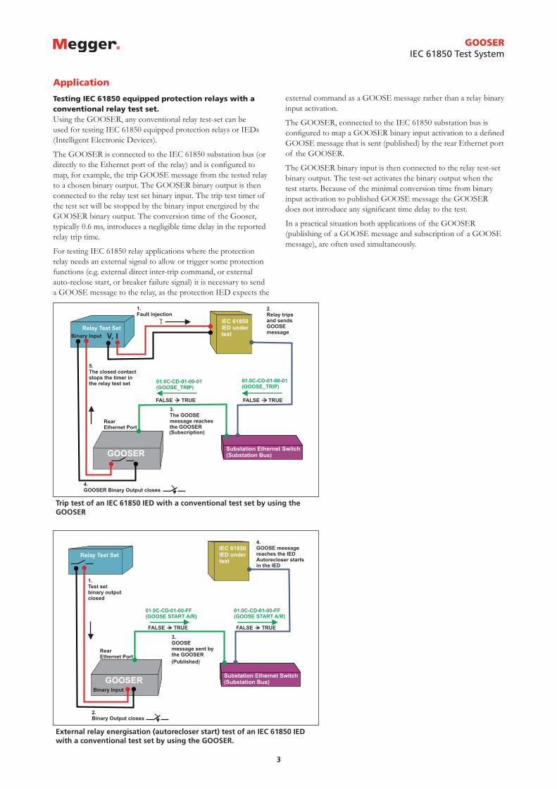
Trip test of an IEC 61850 IED with a conventional test set by using the GOOSER
External relay energisation (autorecloser start) test of an IEC 61850 IED with a conventional test set by using the GOOSER.
GOOSERIEC 61850 Test System
Application
Testing IEC 61850 equipped protection relays with a conventional relay test set.Using the GOOSER, any conventional relay test-set can be used for testing IEC 61850 equipped protection relays or IEDs (Intelligent Electronic Devices).
The GOOSER is connected to the IEC 61850 substation bus (or directly to the Ethernet port of the relay) and is configured to map, for example, the trip GOOSE message from the tested relay to a chosen binary output. The GOOSER binary output is then connected to the relay test set binary input. The trip test timer of the test set will be stopped by the binary input energized by the GOOSER binary output. The conversion time of the Gooser, typically 0.6 ms, introduces a negligible time delay in the reported relay trip time.
For testing IEC 61850 relay applications where the protection relay needs an external signal to allow or trigger some protection functions (e.g. external direct inter-trip command, or external auto-reclose start, or breaker failure signal) it is necessary to send a GOOSE message to the relay, as the protection IED expects the
external command as a GOOSE message rather than a relay binary input activation.
The GOOSER, connected to the IEC 61850 substation bus is configured to map a GOOSER binary input activation to a defined GOOSE message that is sent (published) by the rear Ethernet port of the GOOSER.
The GOOSER binary input is then connected to the relay test-set binary output. The test-set activates the binary output when the test starts. Because of the minimal conversion time from binary input activation to published GOOSE message the GOOSER does not introduce any significant time delay to the test.
In a practical situation both applications of the GOOSER (publishing of a GOOSE message and subscription of a GOOSE message), are often used simultaneously.

4
An IP message sent by the PC cannot reach the substation bus because the data flow is only enabled in one direction: from the “IEC 61850 port” to the “PC COM” port.
The GOOSER used for testing interlocking and control systems. Real time led indication of GOOSE messages and using the capability to drive inductive loads from the binary outputs.
GOOSERIEC 61850 Test System
Security – Secure Substation Access Point.The GOOSER allows working with GOOSE messages without need to connect a PC to the IEC 61850 substation bus. The GOOSER is equipped with two separated Ethernet ports. The rear port is the IEC 61850-8-1 port, and it is connected to the substation bus. The GOOSE messages are transparently forwarded by the GOOSER firmware from the rear port to the front Ethernet (PC COM) port. A PC connected to the front port can display the GOOSE messages through a third party network analyzer or by using the PC-GOOSER software. Note that it is not possible for the private traffic between the PC and the GOOSER to pass through onto the substation bus, which is physically separate and connected to the rear port.
Because of this principle it is possible to use the GOOSER as a Secure Access Point for the substation network. The rear port on the GOOSER is connected to the substation bus and the GOOSE messages are available on the front port for substation bus monitoring. Notice that no settings are required for activating this feature of the GOOSER which means that no special testing is required at the substation to verify it.
Testing the substation interlocking systemWhen testing substation interlocking/control applications it is often necessary to rapidly visualize the status of several GOOSE messages at the same time. It will also be necessary to interface the interlocking signals (GOOSE messages) with a model, often electromechanical, of the system that is to be controlled. (i.e.The circuit breaker, the disconnector or the entire bay).
The GOOSER binary outputs are powerful enough to drive external auxiliary relays to represent the primary equipment that has to be controlled. The binary outputs have a breaking capacity of 250 mA DC on inductive load with 40 ms time constant at 110 V DC.
For example, it is possible to receive two GOOSE messages: GOOSE_CLOSE and GOOSE_OPEN (that are sent from a control IED) to activate two different binary outputs of the GOOSER. With the two binary outputs one bi-stable relay is operated (open and close coils) simulating the circuit breaker operations. The auxiliary contacts of the bi-stable relay are then connected to binary inputs of the GOOSER that will send back to the controller IED the GOOSE message containing the breaker position (GOOSE_CBPOS.).
GOOSER can map double indication (double point) to the binary inputs/outputs, this type of data set content being very common in control/interlocking applications.
The LED indication of the binary outputs from the GOOSER shows immediately the actual status of the GOOSE messages available on the substation network (10 + 10 LEDs).

5
Mapping of GOOSER inputs and outputs to different GOOSE messages.
GOOSERIEC 61850 Test System
PC-GOOSER – Easy mapping and powerful GOOSE message troubleshootingThe GOOSER can be controlled (mapping of the GOOSE messages to physical inputs and/or outputs) using the supplied PC-GOOSER software.
The list of the GOOSE messages to be mapped can be obtained by importing an SCL file or by scanning the network and searching for available GOOSE messages on the GOOSER front Ethernet port.
The unit can map the selected GOOSE messages to the chosen binary inputs or outputs of the GOOSER. The mapping instruction is sent directly to the test equipment or it can be saved as a file on a USB memory stick that can be read by the GOOSER.
The PC-GOOSER software provides mapping of binary information of the GOOSE data set (single point and double point) to GOOSER inputs and outputs.
Other data set information like real numbers, integer, time etc., not relevant to the inputs and outputs of the GOOSER can also be received and published by the GOOSER. This allows the handling of GOOSE messages containing a complex data set where only part of the data is of interest.
GOOSE monitoring with online indication of status change.The PC GOOSER is easy to use and provide useful up-front monitoring information from the “sniffed” GOOSE messages. If the dataset of a captured GOOSE message changes any value, the GOOSE message shown on the Captured messages list will change its color prompting the user that the GOOSE message has changed its value in the dataset. This is useful when you want to make a quick search for a particular GOOSE message available on the network where a large amount of GOOSE messages are published. For instance a GOOSE message carrying the circuit breaker position will change its color and therefore is easy to identify when the circuit breaker is operated. The protection relay test engineer will easily identify the GOOSE messages sent by an IED in the substation by injecting a fault into the IED and using the PC GOOSER to check only the GOOSE messages that have changed their status among several hundred that did not.
In the adjacent figure you can see that the GOOSE message 01-0C-CD-01-00-03 has changed some values in its dataset (indicated by the yellow color). By exploring the GOOSE message one can see which part of the dataset that has changed value, here indicated by the red color. It can also be seen that the dataset of
Monitoring captured GOOSE messages with online indication of status change.
the GOOSE messages 01-0C-CD-01-00-10 and 01-0C-CD-01-01-AA has not changed as they are not colored in yellow.
Advanced GOOSE Filter capabilities are also enabled using the PC GOOSER, while “sniffing” the network, in order to allow you to monitor the GOOSE messages of interest only.

6
A succesful GOOSE merge between a “network GOOSE” (green) and an “SCL GOOSE” (black).
GOOSERIEC 61850 Test System
GOOSE Merge
The PC-GOOSER application also contains a GOOSE Merge feature. The list of “sniffed” GOOSE messages can be merged with the list of the SCL file GOOSE messages. If the “sniffed” GOOSE message is recognized to be the same as the GOOSE message within the SCL file, the merge will succeed and one single GOOSE message will be shown in the resulting GOOSE message list and merge indicated with an”M”symbol. If the merge does not succeed, the PC-GOOSER will show the two GOOSE messages (“sniffed one” and “SCL one”) one below each others in the resulting list, indicating that there are some differences. This information can be used to help identify problems within a IEC61850 network.

Specifications GOOSERThe specifications are valid for nominal voltage supply and at an ambient temperature of +25°C (77°F). Specifications are subject to change without notice.EnvironmentApplication field The instrument is intended for use
in high-voltage substations and industrial environments.
Measurement category CAT I, transient voltage 1500 VTemperature, operating 0°C to +50°C (32°F to +122°F)Temperature storage & transp. -20°C to +70°C (-4°F to +158°F)Vibration IEC 60068-2 - 6Shock (non-operating) IEC 60068-2-27Humidity 5% – 95% RH, non-condensingAltitude (operational) <3000 mPollution degree 2CE-markingEMC 2004/108/ECLVD 2006/95/ECGeneralMains voltage 100 – 230 V AC, 50-60 HzCurrent consumption 1 A (max)Fuses, F1 / F2 F 2ADimensions
Portable version 446 x 290 x 180 mm (17.6" x 11.4" x 7.1")
Rack mounting version 19"Weight 8.5 kg (18.7 lbs) 18.8 kg (41.4 lbs)
with accessories and transport caseUser interface 6" LCD touchscreenBINARY INPUTS, 1...10Number 10Voltage sense
Max voltage 250 V DCTransition level Approx. 15 V DC
Protection Self-protected against wrong con-nection
User feedback Small LEDGalvanic isolation Groupwise 3+3+2+2
Contact senseOutput voltage 19 VDCShort-circuit current 15 mA
BINARY OUTPUTS, 1...10Number 10Protection Self-protected against wrong con-
nection. Built-in current limiterType Normally open solid state contact
Rated current range 0 – 250 mA DCRated voltage range 48 – 220 V DCBreaking capacity DC at L/R <= 40 ms
110 V DC 0.25 A
Galvanic isolation 10 separate outputsWithstand voltage 250 V DC
User feedback Small LEDCommunication portsIEC 61850 Ethernet RJ-45 100 MbpsPC COM Ethernet RJ-45 100 MbpsUSB MEMORY USB 2.0 type AMappable GOOSE messages to inputs/outputsBoolean (single point indica-tion)
Explicit and one level structured data set
2-bit string (double point indication)
Explicit and one level structured data set
Conversion time GOOSE – Electric signalGOOSE → Binary Output 0,6 ms typicalBinary Input → GOOSE 0,5 ms typicalPublishable GOOSE messages Boolean, 2-bit String, Explicit and one level structured
data set. Value according to mapped Input or default or sniffed data if not mapped.
n-bit String, Integer, Real, Time
Explicit and one level structured data set. Value according to de-fault or sniffed data
SCL file importing From IEC 61850 Edition 1 cid, scd, icd, xmlFrom IEC 61850 Edition 2 sed, iid
GOOSERIEC 61850 Test System
SWEDENMegger Sweden AB Eldarvägen 4, Box 2970 SE-187 29 TÄBY T +46 8 510 195 00 F +46 8 510 195 95 E [email protected]
Other Technical Sales OfficesDallas USA, Norristown USA, Toronto CANADA, Trappes FRANCE, Oberursel GERMANY, Johannesburg SOUTH AFRICA, Kingdom of BAHRAIN Mumbai INDIA, Chonburi THAILAND Sydney AUSTRALIA
UK Archcliffe Road Dover CT17 9EN England T +44 (0) 1304 502101 F +44 (0) 1304 207342
Registered to ISO 9001 and 14001
Subject to change without notice.
Art.No. ZI-CL01E • Doc. CL0117AE • 2009
GOOSER_DS_en_V01www.megger.comMegger is a registered trademark
Ordering informationItem Art. No.
GOOSER Portable versionIncl. PC-GOOSER CL-19000
GOOSER Portable versionIncl. PC-GOOSER, Ethernet cable 2 m (GA-00982), Ethernet cable 10 m (GA-00984), USB memory stick, Cable kit for GOOSER test cables (GA-00020) and soft case (GD-00215) CL-19090
GOOSER Portable versionIncl. PC-GOOSER, Ethernet cable 2 m (GA-00982), Ethernet cable 10 m (GA-00984), USB memory stick, Cable kit for GOOSER test cables (GA-00020) and hard case (GD-00500) CL-19091
GOOSER 19” rack mounting versionIncl. PC-GOOSER CL-19005
GOOSER 19” rack mounting versionIncl. PC-GOOSER, Ethernet cable 2 m (GA-00982), Ethernet cable 10 m (GA-00984), USB memory stick, Cable kit for GOOSER test cables (GA-00020) and hard case (GD-00500) CL-19095
Item Art. No.
OptionalElectrical / Fiber Optical Ethernet converter – (RJ45)/(ST) standard multimode HC-04260
Optical fiber cable, 5 m, ST-ST GA-00986
Optical fiber cable, 5 m, LC-ST GA-00987
Cable kit for GOOSER test cablesBanana plug, 2p tp black (Jumper) - 3 pcs Test cable red, 0.25 m - 10 pcs Test cable black, 1 m- 5 pcs Test cable red, 1 m - 5 pcs GA-00020
Ethernet cable, 2 m, non shielded, crossed, red GA-00982
Ethernet cable, 3 m, shielded, straight, grey GA-00985
Ethernet cable, 10 m, shielded, straight, grey GA-00984