gold standard toaster · p/n 1012002 rev. b 04/18. gold standard toaster. owner’s manual. model...
TRANSCRIPT

P/N 1012002 Rev. B 04/18
Gold Standard Toaster
owner’s manualModel GST-3V
Manufacturing Numbers:9210881
www.ajantunes.com

GST-3V BUN TOASTER
2 P/N 1012002 Rev. B 04/18
OWNER INFORMATION
Fill in the information below and have it handy when calling your Authorized Service Agency for assistance. The serial number is on the specification plate located on the rear of the unit.
Purchased From:
Date of Purchase:
Model No.:
Serial No.:
Mfg. No.:
Network ID Number:
Refer to the service agency directory packaged with your manual and fill in the information below:
Authorized Service Agency
Name:
Phone No.:
Address:
Use only genuine Roundup replacement parts in this unit. Use of replacement parts other than those sup-plied by the manufacturer will void the warranty. Your Authorized Service Agency has been factory trained and has a complete supply of parts for this toaster.
You may also contact the factory at 1-877-392-7854 (North America only), or 630-784-1000 if you have trouble locating your local Authorized Service Agency.
IMPORTANT! Keep these instructions for future reference. If the unit changes ownership, be sure this manual accompanies the equipment.
Warranty InformationPlease read the full text of the Limited Warranty in this manual. If the unit arrives damaged, contact the carrier immediately and file a damage claim with them. Save all packing materials when filing a claim. Freight dam-age claims are the responsibility of the purchaser and are not covered under warranty.
The warranty does NOT extend to:
• Damages caused in shipment or damage as resultof improper use.
• Installation of electrical service.• Normal maintenance as outlined in this manual.• Malfunction resulting from improper maintenance.• Damage caused by abuse or careless handling.• Damage from moisture into electrical components.• Damage from tampering with, removal of, or
changing any preset control or safety device.
GeneralThis manual provides the safety, installation, and operating procedures for this unit. Please read this manual prior to installing and operating the unit.
This unit is manufactured from the finest materials available and assembled to Roundup’s strict quality standards. This unit has been tested at the factory to ensure dependable trouble-free operation.
Service/Technical AssistanceIf you experience any problems with the installation or operation of your unit, contact your Authorized Service Agency.
Owner Information .....................................................2Warranty Information .................................................2General ......................................................................2Service/Technical Assistance ....................................2
Specifications .............................................................3Electrical Specifications & Plug Configuration ..........3Dimensions ................................................................3
Important Safety Information ....................................4Installation ...................................................................5
Unpacking ..................................................................5Location .....................................................................5
Operation .....................................................................6Operating Instructions ...............................................6User Mode .................................................................6Manager Mode ..........................................................6Safety Features .........................................................7
Maintenance ................................................................8Daily Cleaning ...........................................................8Replacing Belts (Quarterly) .....................................10Cleaning the Top Cooling Fan and Electrical Housing (Annually) ................................................................12Cleaning the Rear Cooling Fan and Electrical Housing (Annually) ................................................................12
Troubleshooting .......................................................13Replacement Parts ...................................................16Wiring Diagram .........................................................23
Limited Warranty .....................................................24

GST-3V BUN TOASTER
3P/N 1012002 Rev. B 04/18
SPECIFICATIONS
CAUTIONAll electrical connections must be in accordance with local electrical codes and any other applicable codes.
24 5/8”(625 mm)
25 1/4”(641 mm)
14 9/16”(370 mm)
Dimensions
Electrical Specifications & Plug ConfigurationModel & Mfg. No Volt Watts Hz. Plug
DescriptionPlug
Configuration
GST-3V 9210881 220-240 3180-3750 50/60 IEC-309 Pin & Sleeve,
16 Amp., 230 Volt

GST-3V BUN TOASTER
4 P/N 1012002 Rev. B 04/18
IMPORTANT SAFETY INFORMATIONIn addition to the warnings and cautions in this manual, use the following guidelines for safe operation of the unit.
• Read all instructions before using equipment.• For your safety, the equipment is furnished with
a properly grounded cord connector. Do NOTattempt to defeat the grounded connector.
• Install or locate the equipment only for its intend-ed use as described in this manual. Do NOT usecorrosive chemicals in and/or on this equipment.
• Do NOT operate this equipment if it has adamaged cord or plug, if it is not working properly,or if it has been damaged or dropped.
• This equipment should be serviced by qualifiedpersonnel only. Contact the nearest AuthorizedService Agency for adjustment or repair.
• Do NOT block or cover any openings on the unit.• Do NOT immerse cord or plug in water.• Keep cord away from heated surfaces.• Do NOT allow cord to hang over edge of table or
counter.• Do NOT clean this appliance with a water jet.
The following warnings and cautions appear throughout this manual and should be carefully observed.
• Turn the unit off, wait for the cool-down procedureto complete its cycle, and disconnect the powercord before performing any service or mainte-nance on the unit.
NOTE: Turning off the power switch does NOT turn off all power to the unit. When the unit is plugged in and turned off, an LED light flashes to indicate that the power cord is plugged in.
• The procedures in this chapter may includethe use of chemical products. These chemicalproducts will be highlighted with bold face let-ters followed by the abbreviated HCS (HazardCommunication Standard). See HazardCommunication Standard manual for the appro-priated Material Safety Data Sheets (MSDS).
• The equipment should be grounded according tolocal electrical codes to prevent the possibility ofelectrical shock. It requires a grounded recep-tacle with separate electrical lines, protected byfuses or circuit breaker of the proper rating.
• Bread may burn. Therefore toasters must not beused near or below curtains or other combustiblewalls and materials. Failure to maintain safeoperating distances may cause discoloration orcombustion.
WARNINGELECTRICAL SHOCK HAZARD. FAILURE TO
FOLLOW THE INSTRUCTIONS IN THIS MANUAL COULD RESULT IN SERIOUS INJURY OR DEATH.
• Electrical ground is required on this appliance.• Do NOT modify the power supply cord plug. If
it does not fit the outlet, have a proper outletinstalled by a qualified electrician.
• Do NOT use an extension cord with this appliance.• The toaster should be grounded according to local
electrical codes to prevent the possibility of electri-cal shock. It requires a grounded receptacle withseparate electrical lines, protected by fuses or cir-cuit breaker of the proper rating.
• Check with a qualified electrician if you are unsureif the appliance is properly grounded.
CAUTIONBread may burn. Therefore toasters must not be used near or below curtains or other combustible walls and materials. Failure to maintain safe oper-ating distances may cause discoloration or com-bustion.
CAUTIONAll electrical connections must be in accordance with local electrical codes and any other appli-cable codes.
CAUTIONNEVER unplug the power cord while the unit is running! Use the proper shutdown procedure before unplugging the power cord.
WARNINGTo avoid possible personal injury and/or dam-age to the unit, all inspections, tests, and repair of electrical equipment should be performed by QUALIFIED SERVICE PERSONNEL. The unit MUST be completely shut down and unplugged before any internal servicing, except when electrical tests are required. Use extreme care during elec-trical circuit tests. Live circuits will be exposed.
GST-3V BUN TOASTER
5P/N 1012002 Rev. B 04/18
LocationWhen placing the toaster into service, pay attention to the following guidelines:
• Make sure power is off and the toaster is at roomtemperature.
• Do NOT block or cover any openings on the unit.• Do NOT immerse cord or plug in water.• Keep cord away from heated surfaces.• Do NOT allow cord to hang over edge of table or
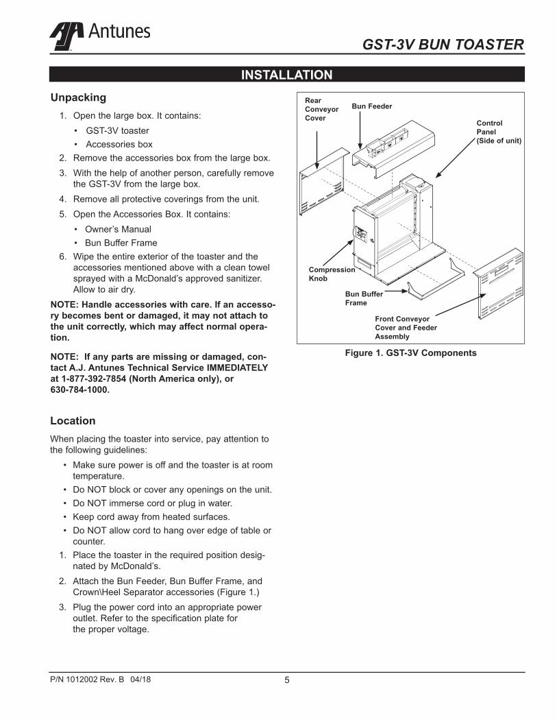
counter.1. Place the toaster in the required position desig-
nated by McDonald’s.2. Attach the Bun Feeder, Bun Buffer Frame, and
Crown\Heel Separator accessories (Figure 1.)3. Plug the power cord into an appropriate power
outlet. Refer to the specification plate forthe proper voltage.
Unpacking1. Open the large box. It contains:
• GST-3V toaster• Accessories box
2. Remove the accessories box from the large box.3. With the help of another person, carefully remove
the GST-3V from the large box.4. Remove all protective coverings from the unit.5. Open the Accessories Box. It contains:
• Owner’s Manual• Bun Buffer Frame
6. Wipe the entire exterior of the toaster and theaccessories mentioned above with a clean towelsprayed with a McDonald’s approved sanitizer.Allow to air dry.
NOTE: Handle accessories with care. If an accesso-ry becomes bent or damaged, it may not attach to the unit correctly, which may affect normal opera-tion.
NOTE: If any parts are missing or damaged, con-tact A.J. Antunes Technical Service IMMEDIATELY at 1-877-392-7854 (North America only), or 630-784-1000.
INSTALLATION
Bun Buffer Frame
Rear Conveyor Cover
Figure 1. GST-3V Components
Control Panel (Side of unit)
Front Conveyor Cover and Feeder Assembly
Compression Knob
Bun Feeder

GST-3V BUN TOASTER
6 P/N 1012002 Rev. B 04/18
Operating InstructionsThe GST-3V toasts Crowns, Heels, Clubs, and other products. Follow these steps to start the GST-3V:
1. Turn on the toaster and wait for warm-up to com-plete.
2. Set the Compression Knob to 4 (recommended).If further adjustments are required see page 8under Adjusting Toast Quality. Refer to the figureon page 7.
3. When the unit reaches operating temperature, thecontrol panel displays “Ready”.
4. Insert product into the designated area of the BunFeeder Assembly with the cut side of the bun fac-ing towards the front. Toasted product drops intothe Bun Buffer.
OPERATION
Figure 2. GST-3V Control Panel and Display
User ModeUser Mode allows an operator to view the toaster set-tings but does not permit any adjustments.
1. Press and hold the PROGRAM button for 5 sec-onds. After 5 seconds, the display will show theactual temperature of the Rear Platen.
2. Press the LIGHTER button to toggle betweenthe setpoint and actual temperature of the RearPlaten Heater.
3. Press the PROGRAM button to proceed to theFront Platen Heater menu. The display shows theactual temperature of the Front Platen.
4. Press the LIGHTER button to toggle betweenthe setpoint and actual temperature of the FrontPlaten.
5. Press the PROGRAM button to proceed to theMotor Menu. The display shows the actual speedof the motor.
6. Press the LIGHTER button to toggle between thesetpoint and actual speed of the Motor.
NOTE: The unit will exit User Mode after 5 seconds of keypad inactivity.
Manager ModeManager Mode allows an operator to view and adjust the following settings:
• Platen A Temperature• Platen B Temperature• Motor Speed• Temperature Units (Celsius or Fahrenheit)• Current Selection: 208 or 240 voltsManager Mode also allows an operator to view (butnot adjust) the Ambient Temperature of the ControlCompartment as well as the number of days of opera-tion.
1. Turn the unit off.2. Turn the power on while holding the PROGRAM
button. Hold the button for 5 seconds until the dis-play shows “EnA.” Release the button.
3. To adjust the Platen Setpoint Temperature, pressthe LIGHTER or DARKER buttons to reach thedesired temperature.
NOTE: The recommended temperature setting for the Rear Platen is 257° C (495° F).

GST-3V BUN TOASTER
7P/N 1012002 Rev. B 04/18
OPERATION (continued)4. Press the PROGRAM button to proceed to the
Front Heater Setpoint Temperature.5. To adjust the Front Heater Setpoint Temperature,
press the LIGHTER or DARKER buttons to reachthe desired temperature.
NOTE: The recommended temperature setting for the front Platen is 271° C (520° F).
6. Press the PROGRAM button to procedure to theMotor Speed Setpoint.
7. Adjust the Motor Speed Setpoint by pressingthe LIGHTER or DARKER buttons to reach thedesired speed.
NOTE: The Motor Speed is adjustable from 1-100. The recommended setting is 75.
8. Press the PROGRAM button to proceed to theTemperature Units.
9. To change the Temperatures units fromFahrenheit or Celsius, press the LIGHTER orDARKER buttons.
10. Press the PROGRAM button to proceedto the Ambient Temperature of the ControlCompartment.
NOTE: No changes can be made to the Ambient Temperature of the Control Compartment. Temperatures under 150° F (66° C) are acceptable.
11. Press and hold the PROGRAM button to saveany changes.
NOTE: The unit exits Manager Mode after 30 sec-onds of keypad inactivity.
Safety FeaturesHI-LIMIT CONTROL
A Hi-Limit Control turns off electrical power to the heat-ers and control circuits if the unit overheats. To reset the control:
1. Allow 10 - 15 minutes for the unit to cool.2. Locate the two Hi-Limit Controls on the rear of the
unit. Remove the two black protective caps.3. Press and release both buttons. Reinstall the pro-
tective caps.NOTE: If the Hi-Limit Controls require continuous resetting, contact your Authorized Service Agency.
Purging buns from ToasterIf buns get stuck in the toaster, press and hold both the UP and DOWN arrow buttons to increase the belt speed until the buns are purged from the toaster.
There are variations in bun products that are used on the A.J Antunes GST-3V toaster such as moisture content, bun formulations, age, tolerances etc. The GST-3V was designed to compensate for bun variations by allowing user to adjust the compression, light/dark (speed) & temperatures settings in order to achieve a Gold Standard toasted product.1. LIGHT DARK ADJUSTMENT: Adjust the light darksetting with the ▲ or ▼ buttons. The default light/darksetting on the GST-3V from the factory is 0 but can beadjusted from Lighter 0-10 to Darker 0-10. Light 10 isthe lightest setting and dark 10 is the darkest. Eachincrease in “lighter” value will increase the pass throughtime and each increase in “darker” value will decreasethe pass through time.
2. TEMPERATURE ADJUSTMENT: Adjust the setpoint temperature on the platens in the program menu.The default temperature settings on the GST-3V are APlaten: 271°C (520°F) and B Platen: 257°C (495° F) .The temperatures can be increased to +/- 50°F (10°C) ifneeded to achieve an acceptable toast quality.
3. COMPRESSION ADJUSTMENT: Adjust the compres-sion knob on the left side of the unit. The default com-pression setting on the GST-3V is 4 but is adjustablefrom 1-7. It is acceptable to adjust the compressionfrom 1-7 as needed to achieve the desired toast qualityand bun compression.

GST-3V BUN TOASTER
8 P/N 1012002 Rev. B 04/18
Daily Cleaning1. Turn the toaster off. The toaster enters a cool-
down mode and will automatically shut downwhen complete.
NOTE: You do NOT need to wait for the cool down to complete.
2. Put on heat-resistant gloves. Remove the frontand rear conveyor covers and the bun buffer.(Figure 5).
3. Clean the outside surfaces of the toaster witha paper towel dampened with an approveddegreaser solution. Be sure to remove all debrisfrom horizontal surfaces of toaster. Allow to airdry.
4. Clean the front and rear Conveyor Covers andBun Buffer with a paper towel dampened with anapproved Glass & Multi-Surface Cleaner. Wipewith a clean sanitizer-soaked towel and allow toair dry.
5. Inspect the belts for any tears, discoloration, ordamage to the Belt Wrap Snaps. Replace anydamaged Belt Wrap as needed. With propermaintenance, the Belt Wraps can last six monthsor longer.
6. If the belts are in good condition, spray a clean,sanitizer-soaked towel with an approved all all-purpose cleanser. Wipe the belts clean. Next,wipe the front belt with a clean, sanitizer-soakedtowel. Allow to air dry.
NOTE: The Belts will continue turning while in cool down mode. You may need to repeat Step 6 more than once to fully clean the belt wraps.
7. Reassemble the unit and return to operation.
MAINTENANCE
Figure 3.
Figure 4. Example of Damaged Belt
BELT IS TORN AND FOLDED. REPLACE BELT.

GST-3V BUN TOASTER
9P/N 1012002 Rev. B 04/18
MAINTENANCE (continued)
BELT IS MISSING SNAPS AND IS DAMAGED. REPLACE BELT.
Figure 5. Example of Damaged Belt
Figure 6. Example of Damaged Belt
BELT IS WRINKLING/DISTRESSED AROUND SNAPS, HAS LOOSE/DAMAGED SNAPS,
AND IS MISSING SNAPS. REPLACE DEFECTIVE BELT.
Wrinkling around Snap
GST-3V BUN TOASTER
10 P/N 1012002 Rev. B 04/18
Figure 8. Conveyor Locks
Figure 7. Conveyor Rollers
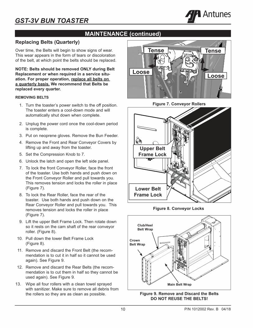
MAINTENANCE (continued)Replacing Belts (Quarterly)Over time, the Belts will begin to show signs of wear. This wear appears in the form of tears or discoloration of the belt, at which point the belts should be replaced.
NOTE: Belts should be removed ONLY during Belt Replacement or when required in a service situ-ation. For proper operation, replace all belts on a quarterly basis, We recommend that Belts be replaced every quarter.
REMOVING BELTS
1. Turn the toaster’s power switch to the off position.The toaster enters a cool-down mode and willautomatically shut down when complete.
2. Unplug the power cord once the cool-down periodis complete.
3. Put on neoprene gloves. Remove the Bun Feeder.4. Remove the Front and Rear Conveyor Covers by
lifting up and away from the toaster.5. Set the Compression Knob to 7.6. Unlock the latch and open the left side panel.7. To lock the front Conveyor Roller, face the front
of the toaster. Use both hands and push down onthe Front Conveyor Roller and pull towards you.This removes tension and locks the roller in place(Figure 7).
8. To lock the Rear Roller, face the rear of thetoaster. Use both hands and push down on theRear Conveyor Roller and pull towards you. Thisremoves tension and locks the roller in place(Figure 7).
9. Lift the upper Belt Frame Lock. Then rotate downso it rests on the cam shaft of the rear conveyorroller. (Figure 8).
10. Pull down the lower Belt Frame Lock(Figure 8).
11. Remove and discard the Front Belt (the recom-mendation is to cut it in half so it cannot be usedagain). See Figure 9.
12. Remove and discard the Rear Belts (the recom-mendation is to cut them in half so they cannot beused again). See Figure 9.
13. Wipe all four rollers with a clean towel sprayedwith sanitizer. Make sure to remove all debris fromthe rollers so they are as clean as possible.
Upper Belt Frame Lock
Lower Belt Frame Lock
Tense
Loose Loose
Tense
Figure 9. Remove and Discard the Belts DO NOT REUSE THE BELTS!
Crown Belt Wrap
Club/Heel Belt Wrap
Main Belt Wrap

GST-3V BUN TOASTER
11P/N 1012002 Rev. B 04/18
MAINTENANCE (continued)
Figure 10. Conveyor Rollers
Figure 11. Conveyor Locks
INSTALLING BELTS
1. Follow the steps for Removing Belts.
2. Wipe both sides of the new Belts with a clean,sanitized towel sprayed with an approved sanitizerand allow to air dry.
3. Wipe all four rollers and the backing plate witha clean towel sprayed with sanitizer. Make sureto remove all debris from the rollers and backingplate so they are as clean as possible.
4. Slide the new front belt gently over the front toproller and front bottom roller.
NOTE: Make sure the belt lines up properly on the rollers. The snaps on the belts should face the inside of the top front roller.
5. Slide the first crown belt over the rear top rollerand rear bottom roller. Repeat this step for theclub/ heel belt and the second crown belt.
NOTE: Make sure the belt lines up properly on the rollers. The snaps on the belts should face the inside of the top rear roller.
6. Return the Front and Rear Belt Rollers to full ten-sion by lifting them up so each roller locks intoplace (Figure 10).
7. Slowly lift up the Lower Belt Frame Lock so theFront and Rear Belt Rollers lock into place (Figure11). If necessary, lift up the cam shaft of the RearBelt Roller while lifting the Lower Belt Frame Lockinto place.
8. Re-engage the Upper Belt Frame Lock by lift-ing up and then locking it in place on the FrontConveyor Assembly (Figure 11).
9. Close and latch the Side Panel.
NOTE: Inform the Store Manager after any Belt Replacement so new Belts can be ordered. To obtain new Belts, contact the factory at 1-877-392-7854 (North America only) or 630-784-1000.
10. Set the Compression Knob to 4.
11. Re-install the Front and Rear Conveyor Coversand then the Bun Feeder Assembly.
12. Plug in the toaster and test the unit beforereturning to service.
Upper Conveyor
Lock
Lower Conveyor
Lock
Tense
Loose Loose
Tense
GST-3V BUN TOASTER
12 P/N 1012002 Rev. B 04/18
MAINTENANCE (continued)
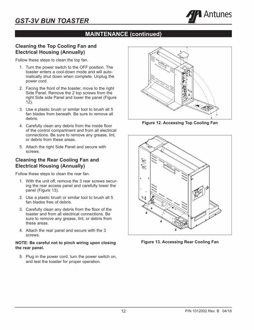
Figure 12. Accessing Top Cooling Fan
Cleaning the Top Cooling Fan and Electrical Housing (Annually)Follow these steps to clean the top fan.
1. Turn the power switch to the OFF position. Thetoaster enters a cool-down mode and will auto-matically shut down when complete. Unplug thepower cord.
2. Facing the front of the toaster, move to the rightSide Panel. Remove the 2 top screws from theright Side side Panel and lower the panel (Figure12).
3. Use a plastic brush or similar tool to brush all 5fan blades from beneath. Be sure to remove alldebris.
4. Carefully clean any debris from the inside floorof the control compartment and from all electricalconnections. Be sure to remove any grease, lint,or debris from these areas.
5. Attach the right Side Panel and secure withscrews.
Cleaning the Rear Cooling Fan and Electrical Housing (Annually)Follow these steps to clean the rear fan.
1. With the unit off, remove the 3 rear screws secur-ing the rear access panel and carefully lower thepanel (Figure 13).
2. Use a plastic brush or similar tool to brush all 5fan blades free of debris.
3. Carefully clean any debris from the floor of thetoaster and from all electrical connections. Besure to remove any grease, lint, or debris fromthese areas.
4. Attach the rear panel and secure with the 3screws.
NOTE: Be careful not to pinch wiring upon closing the rear panel.
5. Plug in the power cord, turn the power switch on,and test the toaster for proper operation.
Figure 13. Accessing Rear Cooling Fan

GST-3V BUN TOASTER
13P/N 1012002 Rev. B 04/18
TROUBLESHOOTING
Problem Possible Cause Corrective ActionControl Display flashes Err 5 continuously. Buns not toasting properly.
The A Platen temperature has not reached the setpoint temperature within 20 minutes.
Allow the unit to warm up for 30 minutes and then recheck. If the Control Display still flashes Err 5, contact your maintenance person or Authorized Service Agency for service.
Failed A Platen Thermocouple. Contact your maintenance person or Authorized Service Agency for service.Failed Control Board
Control Display flashes Err14 continuously. Buns not toasting prop-erly.
The B Platen temperature has not reached the setpoint temperature within 20 minutes.
Allow the unit to warm up for 30 minutes and then recheck. If the Control Display still reads Err 14, contact your maintenance person or Authorized Service Agency for service.
Failed Rear Platen Thermocouple. Contact your maintenance person or Authorized Service Agency for service.Failed Control Board.
Control Display flashes Err 9 continuously.
Control Compartment ambient tem-perature is above 150° F (66° C)
Verify side vents on toaster are unblocked and not near other heating appliances. If problem persists, contact your maintenance person or Authorized Service Agency for service.
Failed Cooling Fan.Failed Control Board
Control Display Flashes Err 19 continuously. Buns Burn.
Failed A Platen Solid State Relay. Contact your maintenance person or Authorized Service Agency for service.Failed Control Board.
Failed A Platen Thermocouple.Control Display flashes Err 18 continuously. Buns Burn.
Failed B Platen Solid State Relay. Contact your maintenance person or Authorized Service Agency for service.Failed Control Board.
Failed B Platen Thermocouple.Control Display flashes Err 13 continuously. Buns not toasting prop-erly.
Loose A Platen Thermocouple con-nection on Control Board or the Front Platen Thermocouple is open.
Re-secure the A Platen Thermocouple to the Control Board. If the Control Display still reads Er 13, check the front Thermocouple for continuity. Contact your maintenance person or Authorized Service Agency for service.
Failed Control Board.
Control Display flashes Err 11 continuously. Buns not toasting prop-erly.
Loose B Platen Thermocouple con-nection on Control Board or the Rear Platen thermocouple is open.
Re-secure the B Platen Thermocouple connection to the Control Board. If the Control Display still reads Er 11, check the Rear Thermocouple for continuity. Contact your maintenance person or Authorized Service Agency for service.
Failed Control Board.
Control Display flashes Err 12 continuously. Buns not toasting prop-erly.
Shorted A Platen Thermocouple to ground.
Disconnect and re-secure the A Platen Thermocouple connection to the Control Board. If the Control Display still reads Er 12, check the Rear Thermocouple for continuity. Contact your maintenance person or Authorized Service Agency for service.
Failed Control Board
Control Display Flashes Err 10 continuously. Buns not toasting.
Shorted B Platen Thermocouple to ground.
Re-secure the B Platen Thermocouple connection to the Control Board. If the Control Display still reads Er 10, check the Rear Thermocouple for continuity. Contact your maintenance person or Authorized Service Agency for service.
Failed Control Board.

GST-3V BUN TOASTER
14 P/N 1012002 Rev. B 04/18
TROUBLESHOOTING (continued)
Problem Possible Cause Corrective ActionControl Display flashes Err 20.
Mechanical bind in one or both con-veyors.
Enter “user mode” to check the motor speed. Check both conveyors for mechanical binds. Test the motor. Replace necessary parts. Contact your maintenance person or Authorized Service Agency for service.
Worn or damaged Ball Bearings.Drive chain or sprockets damaged.Failed Motor.Failed Control Board.
Control Display flashes Err 8
Motor is running when it shouldn’t be.
Contact your maintenance person or Authorized Service Agency for service.
Crowns and/or Heels must be forced into the toaster. Buns sticking and burning.
Silicone Belts not cleaned properly. Clean Silicone Belts as described in the Maintenance section of this manual.
Silicone Belts are not tack/sticky to the touch (replace every 4-6 months).
Clean Silicone belts. If the Silicone Belts are too worn, replace them as described in the Maintenance section of this manual.
Silicone Belts are dirty, worn, or damaged (replace every 4-6 months).
Clean or replace Silicone Belts as described in the Maintenance section of this manual.
Buns not toasting ade-quately.
One of the Conveyor top shafts is stuck in the lower lock position.
Inspect positions of the shafts as described in the Maintenance section of this manual.
Either both Upper/Lower Conveyor locks are not properly locked in place.
Inspect the proper position of the locks as described in the Maintenance section of this manual.
Compression side door will not close.
Either both Upper/Lower Conveyor Locks are not properly locked in place.
Inspect the proper position of the locks as described in the Maintenance section of this manual.
The lock on the Compression Side Door is in the locked position when trying to close the door.
Turn the lock to the unlocked position before clos-ing the door.
Fan is making an unusu-al sound.
Failed Cooling Fan. Verify vents on toaster are unblocked and not near other heating appliances. Clean fans as described in the Maintenance section of this man-ual. If problem persists, contact your maintenance person or Authorized Service Agency for service.
Cooling Fan is dirty and needs to be cleaned.
Control Display flashes Err 17 continuously. Buns are not toasting properly.
A platen Hi-Limit Control is tripped. Allow the unit to cool and reset the A platen Hi-Limit Control. If it trips again, contact your maintenance person or Authorized Service Agency for service.
Control Display flashes Err 16 continuously. Buns are not toasting properly.
B Platen Hi-Limit Control is tripped. Allow the unit to cool and reset the B platen Hi-Limit Control. If it trips again, contact your maintenance person or Authorized Service Agency for service.
GST-3V BUN TOASTER
15P/N 1012002 Rev. B 04/18
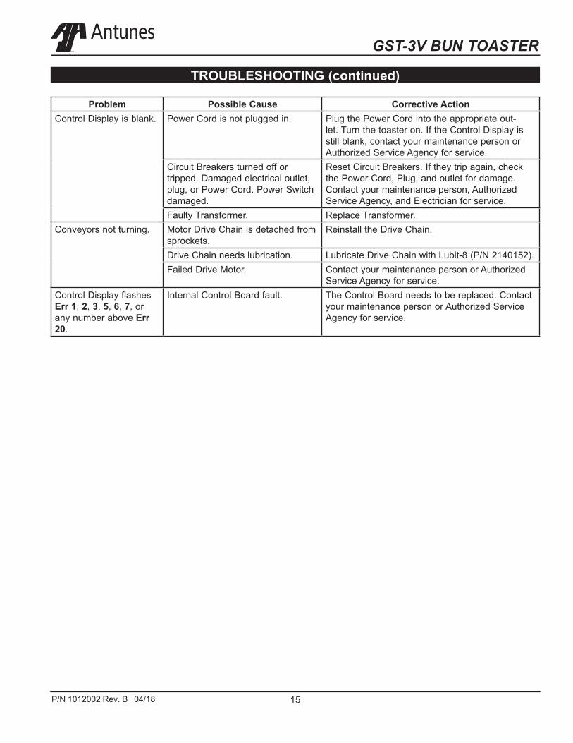
TROUBLESHOOTING (continued)
Problem Possible Cause Corrective ActionControl Display is blank. Power Cord is not plugged in. Plug the Power Cord into the appropriate out-
let. Turn the toaster on. If the Control Display is still blank, contact your maintenance person or Authorized Service Agency for service.
Circuit Breakers turned off or tripped. Damaged electrical outlet, plug, or Power Cord. Power Switch damaged.
Reset Circuit Breakers. If they trip again, check the Power Cord, Plug, and outlet for damage. Contact your maintenance person, Authorized Service Agency, and Electrician for service.
Faulty Transformer. Replace Transformer.Conveyors not turning. Motor Drive Chain is detached from
sprockets.Reinstall the Drive Chain.
Drive Chain needs lubrication. Lubricate Drive Chain with Lubit-8 (P/N 2140152).Failed Drive Motor. Contact your maintenance person or Authorized
Service Agency for service.Control Display flashes Err 1, 2, 3, 5, 6, 7, or any number above Err 20.
Internal Control Board fault. The Control Board needs to be replaced. Contact your maintenance person or Authorized Service Agency for service.

GST-3V BUN TOASTER
16 P/N 1012002 Rev. B 04/18
1 0012603 Sprocket / Tensioner Bracket Assy 12 0012592 Sprocket /Bearing Assembly 13 0506185 Bracket, Chain Tensioner 14 2140109 Loctite # 242 (Blue) 15 3310101 Nut, Hex 5/16 - 18 16 3310103 Shoulder Bolt 3/8” X 1” 17 3310106 Lock Washer 18 0012604 Sprocket / Retainer Assy 19 0012592 Sprocket /Bearing Assembly 110 0506146 Retainer Idler 111 2120118 Washer, Flat 112 2140109 Loctite # 242 (Blue) 213 331P101* Nut, Hex 5/16 - 18 114 3310103 Shoulder Bolt 3/8” X 1” 115 331P106* Lock Washer 116 0012814 Cam Bracket And Thrust 1
Strip Assembly, LH 17 0013167 Housing Assembly 118 0013166 Base / Heater Assembly 119 0021689 Weldment, End Housing 120 0021714 Weldment, End Housing Rod Support 121 0022117 Weldment, Inner Base 122 0022118 Weldment, Control Housing 123 0200345 Base Gasket, 23.94” LG 224 0200355 Base Gasket, 11.30” LG 225 0400119 Bushing, Shorty 5/8” 226 0400418 Push In Grommet For 1-1/8” Dia. Hole 127 0506083 Spacer 228 0506174 End Covr Bottom 129 0800474 Rod, Belt Cover 430 2100212 Handle, Pocket Pull, Snap-In 131 2140101 Adhesive/ Sealant - RTV 132 2140109 Loctite # 242 (Blue) 133 308P144* Screw, #8-32 X 1/4” (#6 Head) 134 308P157* Screw, Tap 8-32 X 3/8”LG 135 3080203 Screw, Tap 8-32 X 3/8” W/Int. 11
Tooth Washer 36 310P102* Washer, Int. Tooth-Lock,#10 137 310P110* Screw, Mach. #10-32 X 1/2” 138 310P199! Scr, #10-32 X 3/8 Lg Socket HD Cap 139 310P204* Fillister Head Phillips Screw 1
# 10-32 X .25 40 0013178 Adj. Platen Assembly 141 0013181 Relay - Sink Bracket Assy 142 0507247 Heat Sink, Relay 143 308P157* Screw, Tap 8-32 X 3/8”LG 144 4010187 Transformer, 240 Vac/12Vac 145 4050240 Relay, Solid State Dual Pole 1
W/Conn-Recept 46 0013183 Motor / Sprocket Assembly 147 0506157 Motor Plate 1
Item Part No. Description Qty. Item Part No. Description Qty.48 2140109 Loctite # 242 (Blue) 249 2150316 Sprocket, 25B12 3/8” Bore 150 310P199* Scr, #10-32 X 3/8 LG Socket HD Cap 1
1111111112111
1111111111111
51 4000186 Motor, 230V 52 0013184 Cam Brkt & Thrust Strip Assy, Rh 53 7001628 End Cover Assembly Kit54 0013217 Bun Feeder Assembly 55 0013250 Electrical Panel Assembly 56 0022185 Electrical Panel Wldmnt 57 0506170 Fan Cover 58 1000900 Label - Warning 59 1001213 Label - Shock Hazard 60 21000-0043 Spacer, 3/8 CBS Thread Female 61 308P124* Screw, Mach One-Way #8-32 62 308P143* Nut, Hex ‘Keps’ #8-32 63 310P213* Screw, Phpnhd
#10-16 X 3/4” Thrd Form 64 4000202 Fan, Axial - 230V, Metal Hsg & Imp 65 4050236 Contactor, 2 Pole No 66 4070198 Snubber Board 67 0013307 Control Cover Assembly 68 0022110 Weldment, Control Housing Cover 69 1000900 Label - Warning 70 1001213 Label - Shock Hazard 71 1001561 Label, ID - A 72 1001562 Label, ID - B 73 1001599 Label, Control 75 1002650 Wiring Diagram Label 76 2100212 Handle, Pocket Pull, Snap-In 77 2180445 Edge Trim Piece, 7” 78 304P105* Nut, Hex ‘Keps’ #4-40 179 4070230 Asy-Pcb, Main Go To Market (MCD) 180 0021983 Weldment, Thermocouple Tube 181 0022101 Weldment, Idler Roller Front Top 282 0022103 Weldment, Drive Roller Front Bottom 283 0022111 Weldment, Conveyor Cover - Front 184 0022114 Cover Weldment 185 0022115 Weldment, Adj. Platen Frame 186 0022116 Weldment, Fixed Platen Frame 187 0022283 Wment, Bearing Brkt & 2
Spring Guide- LG 88 0022284 Wment, Bearing Brkt & 2
Spring Guide - RG 89 0022294 Weldment, Filter Bracket 190 0100292 Platen, Main 230V, 2300W 191 0400147 Bushing, Shorty 7/8” 192 0400427 Insulation, Main Platen 193 0504320 Spacer 0.781 X 1.125 X 0.06” 1094 0506144 Plate, Tensioner RG 295 0506163 Bracket, Tensioner 296 0506167 Bracket, Bearing 2
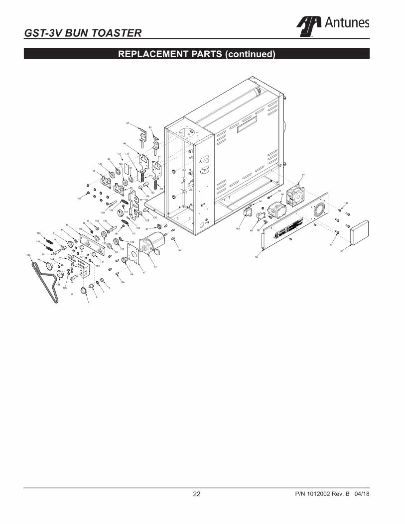
REPLACEMENT PARTS

GST-3V BUN TOASTER
17P/N 1012002 Rev. B 04/18
Item Part No. Description Qty. Item Part No. Description Qty.
REPLACEMENT PARTS (continued)
97 0506278 Spacer, .312 X .187 X .105 398 0506291 Bracket, Tensioner- End Hsg, Rear 199 0506292 Bracket, Tensioner- End Hsg, Front 1100 0506293 Plate, Tensioner - End Hsg, Rear 1101 0506294 Plate, Tensioner - End Hsg, Front 1102 0506736 Bracket, Housing Locking 1103 0507112 Support Bracket, RG 1104 0507113 Support Bracket, LG 1105 0507114 Back Conveyor Cover 1106 0507115 Bracket, Bun Stop 1107 0507129 Insulation Plate 1108 0507246 Cover, Duct Fan 1109 0600143 Spring, Compression Setting 2110 0600157 Spring, Chain Tension 2111 0600158 Spring, Roller Tension 4112 0600159 Spring, Cam Adj 2113 0700956 Cable Assembly - Gnd 1114 0700963 Wire Set, SSR Hi Voltage 1115 0700964 Wire Set, Club Voltage 1116 0700965 Wire Set, Control 1117 0700966 Wire Set, Fan Xfmr 1118 0700967 Wire Set, Line Filter 1119 1001452 Label, Pvc Removal 1120 2100212 Handle, Pocket Pull, Snap-In 2121 2100253 Knob, 1/4” Shaft, Push-On 1122 2100334 Thrust Strip, Teflon 4123 2110197 Clip, Steel Cable 1124 2120213 Spacer, Frame & Platen LG 4125 2120216 Spacer,Upper Locking Plate, Front 1126 2120217 Spacer,Upper Locking Plate, Rear 1127 2120221 Spacer, 0.69 X 0.503 X 0.359 2128 2120223 Sleeve Bearing, .50” Od X .75” LG 2129 2120224 Sleeve Bearing, .50” Od X .375” LG 2130 2120260 Spacer, Adjustable Frame Rh 2131 2120263 Spacer, Platen RH 2132 2140109 Loctite # 242 (Blue) 1133 2140125 Lubricant, White, PTFE 1134 2150185 Sprocket, 25B18, 1/2” Bore 2135 2150285 Bearing, Single Groove S/S 8136 2150324 Chain, Drive 1137 2150362 Cam, HBCS 2138 2150406 Cam Shaft 1139 300P123* Ring, Retaining, External 1
140 304P105* Nut, Hex ‘Keps’ #4-40 1141 306P130* Nut, Hex Keps #6-32 (Small Pattern) 1142 308P102* Washer, Int. Tooth #8 1143 308P124* Screw, Mach One-Way #8-32 1144 308P142* Washer, Flat #8 1145 308P143* Nut, Hex ‘Keps’ #8-32 1146 308P145* Nut, Hex Acorn #08-32 Low Crown 1147 308P157* Screw, Tap 8-32 X 3/8”LG 1148 308P164* Screw, Mach. #8-32 X 1” 1149 308P193* Scr, Mach #8-32 X 1 1/4” SLTFLTHD 1150 308P203* Screw, Tap 8-32 X 3/8” 1
W/Int. Tooth Washer 151 308P340* Nut, Hex Acorn Lock #8-32 1152 310P146* Nut, Hex ‘Keps’ #10-32 1153 310P187* Screw Set, #10-32 X 3/8 1
Hex Socket-Cone Point 154 310P199* Scr, #10-32 X 3/8 Lg Socket HD Cap 1155 310P213* Screw, PHPNHD #10-16 X 3/4” 1
Thrd Form 156 310P214* Screw, Hex #10-32 X 1/2” 1157 325P109* Screw, Hexcap 1/4-20 X 1/2” 1158 325P176* Screw, Flange Hex Head Cap 1159 325P193* Screw, Hex Head, 1
#1/4-20 X 1.375”, S.S. 160 325P194* Screw, Hex Hd, #1/4-20 X 2.00”, S.S. 4161 4000202 Fan, Axial - 230V, Metal Hsg & Imp 1162 4010221 Cap-Mp, Motor Run 1163 4030352 Thermostat, Hi-Limit 700°F 2164 4050229 Filter, Line 1165 4051045 Thermocouple Type “K” (Open End) 2166 4060107 Cable Tie, 1/8W X 5” 1167 4060374 Ground Lug 1168 4060398 Terminal Block, S-Series 1169 4070154 Varistor Board 1170 0700947 Power Cord IEC-309 Pin & Sleeve, 1
16 Amp., 230 Volt (Mfg. No. 9210859 & 9210861)
171 0400375 Strain Relief 1172 0400376 Lock Nut, Conduit 3/4” NPT 1 * Items available in packages of ten (10)

GST-3V BUN TOASTER
18 P/N 1012002 Rev. B 04/18
54
120 105
106
83
120
24
18
34
2324
23
REPLACEMENT PARTS (continued)

GST-3V BUN TOASTER
19P/N 1012002 Rev. B 04/18
REPLACEMENT PARTS (continued)
126
125159
159
102
26
20
124
12816
109
112
124
160
124
128
37151160
139
139
151
137
160
101100
122
122
88
87
93135
98
152
158
53
53
121
152
99158
96
93135
93
111111
93
13537
152
152

GST-3V BUN TOASTER
20 P/N 1012002 Rev. B 04/18
REPLACEMENT PARTS (continued)156
156
104
84
40
165
81
81
82
82
85
86
139
139
138
165
90 92
107
156148
142
ZX
ZX ZX
103

GST-3V BUN TOASTER
21P/N 1012002 Rev. B 04/18
REPLACEMENT PARTS (continued)
147
108
155
161
43
44
42
45
7879
68
73
147
7677
141
164
89
141
168
149
140
169
163
163
GST-3V BUN TOASTER
22 P/N 1012002 Rev. B 04/18
REPLACEMENT PARTS (continued)
87
88
94
94122 122
111
111130
129
93
93
135 135
95
95
52
130129
153
112
109 151
151
139
159
159
152
1391315
10
119
135
93
13593
152
127
9
14
110
110
134
136
57
2
2
6
145
144
134
3
154
4947
51
50
91
57
63
147
56
162
141
6265
64
6066
127

GST-3V BUN TOASTER
23P/N 1012002 Rev. B 04/18
WIRING DIAGRAM
Limited Warranty
Equipment manufactured by Roundup Food Equipment Division of A.J. Antunes & Co. has been constructed of the finest materials available and manufactured to high quality standards. These units are warranted to be free from electrical and mechanical defects for a period of one (1) year from date of purchase under normal use and service, and when installed in accordance with manufacturer’s recommendations. To insure continued operation of the units, follow the maintenance procedures outlined in the Owner’s Manual. During the first 12 months, electro-mechanical parts, non-overtime labor, and travel expenses up to 2 hours (100 miles/160 km), round trip from the nearest Autho-rized Service Center are covered.
1. This warranty does not cover cost of installation, defects caused by improper storage or handling prior to plac-ing of the Equipment. This warranty does not cover overtime charges or work done by unauthorized serviceagencies or personnel. This warranty does not cover normal maintenance, calibration, or regular adjustmentsas specified in operating and maintenance instructions of this manual, and/or labor involved in moving adjacentobjects to gain access to the equipment. This warranty does not cover consumable/wear items. This war-ranty does not cover damage to the Load Cell or Load Cell Assembly due to abuse, misuse, dropping of unit/shock loads or exceeding maximum weight capacity (4 lbs). This warranty does not cover water contaminationproblems such as foreign material in water lines or inside solenoid valves. It does not cover water pressureproblems or failures resulting from improper/incorrect voltage supply. This warranty does not cover Travel Time& Mileage in excess of 2 hours (100 miles/160 km) round trip from the nearest authorized service agency.
2. Roundup reserves the right to make changes in design or add any improvements on any product. The rightis always reserved to modify equipment because of factors beyond our control and government regulations.Changes to update equipment do not constitute a warranty charge.
3. If shipment is damaged in transit, the purchaser should make a claim directly upon the carrier. Careful inspec-tion should be made of the shipment as soon as it arrives and visible damage should be noted upon the car-rier’s receipt. Damage should be reported to the carrier. This damage is not covered under this warranty.
4. Warranty charges do not include freight or foreign, excise, municipal or other sales or use taxes. All such freightand taxes are the responsibility of the purchaser.
5. This warranty is exclusive and is in lieu of all other warranties, expressed or implied, including any implied war-ranty or merchantability or fitness for a particular purpose, each of which is hereby expressly disclaimed. Theremedies described above are exclusive and in no event shall roundup be liable for special consequential orincidental damages for the breach or delay in performance of this warranty.