gm k?tr. wt 6%wmrm, y -
TRANSCRIPT

1,659,083 Feb.;14, 192s. ' E. H._ CLARK
TELEPHONE EXCHANGE SYSTEM
1 9 Sheets-Shes 5 2 9 1 7. 2 e.
J . Q3
w
n SVKMR
gm Km ?t Rm . wt 6% wwmRm, Y
A’ my
[iyar /7.’ 674/

Feb. 14, 1928. 1,659,083 E. H. CLARK
TELEPHONE EXCHANGE SYSTEM
Filed June 27, 1925 9 Sheets-Sheet 2
K.)

M114, 1928. 1,659,083 - E. H. CLARK
TELEPHONE EXCHANGE SYSTEM
Filed June 27, 1925 9 Sheets-Sheet 5
Q U Q
fdyar /% 04M’
Feb. 14, 1928. _ 1,659,083 ‘ E. H. CLARK
‘TELEPHONE EXCHANGE SYSTEM
Filed June 27‘. 1925 9 Sheets-Sheet 4
hvenfm‘ .[dyar/z’ f/ark


Feb. 14, 1928. E. H. CLARK
1,659,083
TELEPHONE EXCHANGE SYSTEM
Filed June 27, 1925 U
[dyar /% 674M’ I by my
4 Feb. 14, 1928. I 1,659,083 . ‘ E. H. CLARK
TELEPHONE EXCHANGE SYSTEM
' Filed June 27, 1925 9 Sheets-Sheet 7
<: Q Q
101:; ' f4
5 HP ' ,15/ 7.72 73,:
H7 JEEP‘ 702 _
M ‘I 51

1,659,083 Feb. 14, 1928. E. H._ CLARK
TELEPHONE‘ EXCHANGE SYSTEM
Filed June 27, 1925 9 Sheets-Sheet 8
FF“ Fa". v A by


is
10
15
Patented Feb. 14,1928.‘ 1,659,083 UNITED ‘STATES
mean it. CLARK, or RICHMOND HILL, nnwYonK, As'sreu'on T0 wnsrrnnuinnnc TRIO COMPANY, INCORPQBVAEEED, YORK.
TELEFHONE-EXGHANGE sysrnm. Application ?led June 27, 1925. Serial Nb. 39,883;
This invention relates to telephone ex! change systems and more particularly to tele phone systems wherein automatic switches are‘ en'iployed for the establishing and'con trolling of connections‘. I ‘ ‘ Heretofore in telephone systems employ ing switches offche coordinatetype such as the syst'em'disclosed in U. S. patent to S. B. l/Villiams, J 1:, No. 1,517,331, issued December 2, $1924, it'has been the practice totarrange subscribers’ lines as calling lines in groups, each group of lines appearing before a sin gle line. switch, Associated with each line switch for controlling the operation thereof is a master control ‘circuit. When for any reason the master circuit becomes inoperative it has been the usual practice to replace such
‘ ‘circuit by an emergency or substitute circuit.
20
25
3 O
' line
40
'50
Under such concitions it necessarily follows that the emergency apparatus is ei'nployed at con'iparatively infrequent intervals. Fur— thermore in such systems each calling line. for the purpose of extension, has access to the horizontalv links of choline switch alone5 *and to only those trunks appearingv in this switch. ~ Accordingly when a calling line en' counters either an‘ “all links” or an “all trunks” busy condition in the switch before which it appears the extension of such line may be temporarilyretarded until an idle link or an idle trunk occurs. ~ i
It. is an object of this inventiontherefore 'to provide, a highly e?icient arrangement of
switches and controlling circuits there for. > . ‘
According- to one feature of the invention each subscriber’s line has an appearance be fore a plurality of coordinate line switchesQ one switch acting as 'a preferred choice in extending said line. Another feature of the invention relates
to the means for‘ext’ending calling line ‘ through a second choice linevswitch when all the available links in the ?rst choice switch are busy. or when all the trunks appearing in the ?rst choice switch are busy. ' A further feature of the invention relates
to the means for-extending a calling“ line through a ,secondchoice line switch when. either the ?rst choice switch or the master circuit associated therewith encounters trouble. . ~ -
A still further feature relates to a master control circuit which comprises the functions
of_ a regular and an emergency master switch“ 1 - > \ » ‘ 1
~ Another feature of the invention relates to
or‘ new YORK, N. Y., Loom-cannon‘ or NEw~ ‘
55
the means whereby repeated attempts are 1; made to extend a calling line whentrouble' exists in both the ?rst choice switchnnd in the second choice switch. 1 i ' ‘ ~ .
Other features and advantages of the in vention‘ not speci?cally ‘enumerated, above will become apparent after a consideration of the followingv ‘descriptions and the ap— pended claims." . ' _ . ’
Referring to the": drawing, ‘Fig. "1 shows ‘a
60
05'
portion of a. master control circuit associated ~ : with a. particular line switch.“ This ?gure»
‘70 also represents schematically a: trouble indi cator, ‘and means for connecting thetrouble indicator to the control circuit: , .
Fig. Qshows the remaining: portion master circuit ‘partially shown. in Fig. 1.
Fig. 3. shows a pluralityof groups of call. ing lines together with certain allotting and controlling'relays. . . -. ' _ ‘
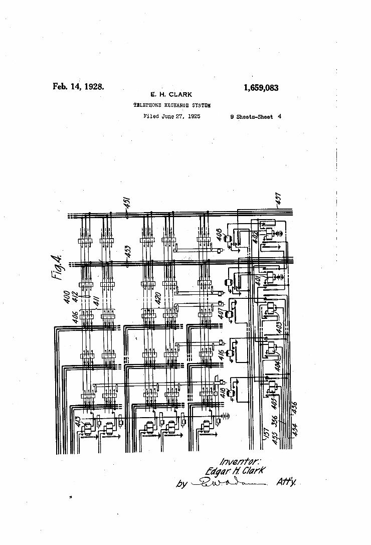
Fig. 4 illustrates a portion of a coordinate lineswitch. ' ‘ ' " . ‘
Figs. 5 and 6 show second mastercontrol' vcircuit associated with a corresponding line switch. ‘ . . ' p .
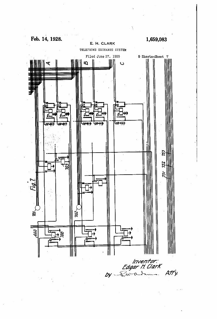
’ Fig.7 shows groups of subscribers’ lines “and associated“ allotting, and control relays.
. Fig. ' 8 . shows 7 a second] coordinate line switchsmf' " o p I K
Fig. 9 isa schematic representation of one form of carrying out the‘ invention.
Fig.‘ 10 represents the manner in ‘which the various sheets of the-drawing are to vbe arranged for the purpose of’ obtaining a unitary disclosure of the. invention.
General»description of circuits and appa ‘ rams. ‘ j- j' .l‘
The line switches 400 andSOO are of the coordinate type such as shown and described in U. S.;patent to J. N. Reynolds 1,507,140; SeptemberQ. 11924, and further shown and described in U. S. PalIEHlZ'tO'S.~B.'W1lllEtII1S, J12, 1,517,331, December 2, 1924. -.Each switch comprises groups of vertical rows of contacts, one group beingallotted to lines and another group allotted to trunks. Each vertical row of contacts has anoperating
is the
75
100
10s’ magnet individual thereto for preparing the ' associated row. For the purpose ofinter connecting the lines and trunks there are
10 “ ' necting magnet as described in
'15
20
25
30
35
40
60
55
60
2
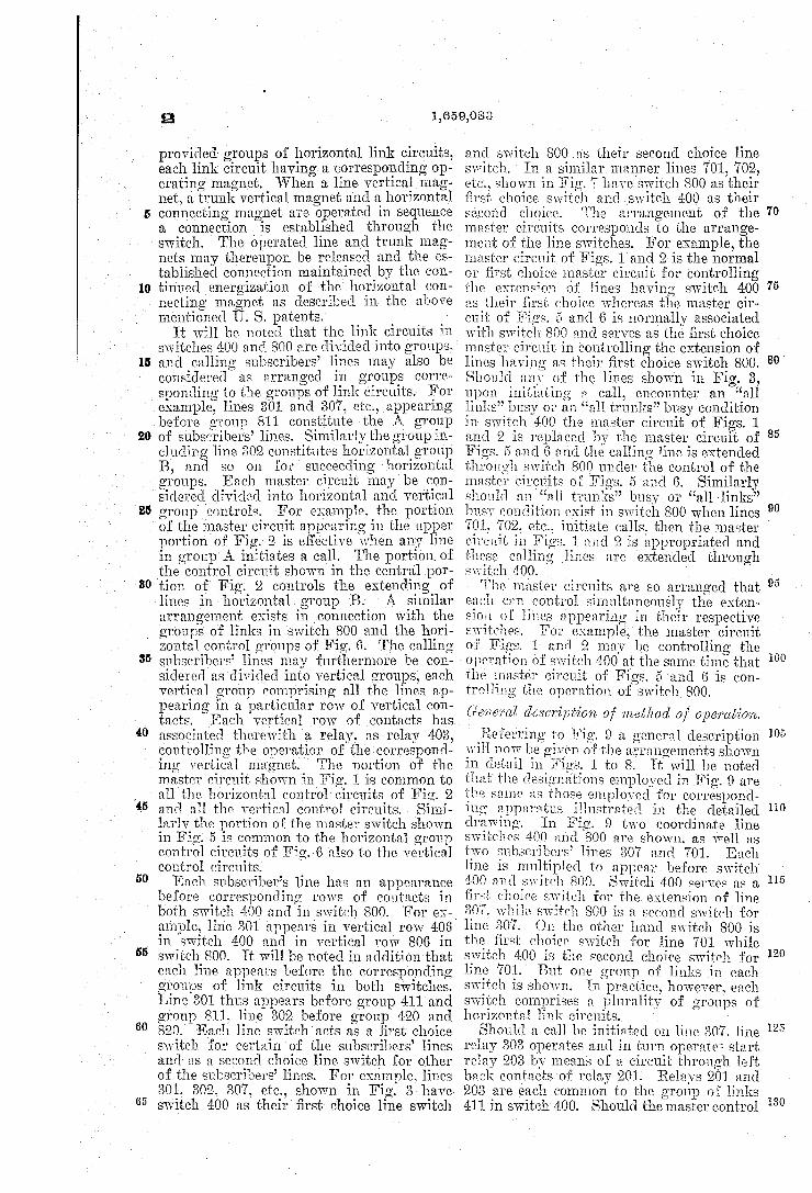
provided groups of horizontal link circuits, each link circuit having a corresponding op-v erating magnet. WVhen a line vertical mag net, a trunk vertical magnet and a. horizontal connecting magnet are operated in sequence a connection is established through the switch. The operated line and trunk mag nets may thereupon be released and the es tablished connection maintained by the con tinued energization of the horizontal con
the above mentioned U. S. patents. _ _
It will be noted that the link circuits in switches 400 and 800 are divided into groups, and calling subscribers’ lines may also be considered as ' arranged in groups corre sponding to the groups of link circuits. For example, lines 301 and 807, etc.7 appearing before group 811 constitute the A group of subscribers’ lines. Similarly the group in cluding line 302 constitutes horizontal group B, and so on for succeeding horizontal groups. Each master circuit may be con sidered divided into horizontal and vertical group ‘controls. For example. the portion of the master circuit appearing in the upper portion of Fig. 2 is effective when any line in group'A initiates a call. The portion of the control circuit shown in the central por tion of Fig. 2 controls the extending of lines in horizontalv group B. A similar arrangement exists in connection with the groups of links in switch 800 and the hori zontal control groups of Fig. 6. The calling subscribers’ lines may furthermore be con sidered as divided into vertical groups, each vertical group comprising all the lines ap pearing in a particular row of vertical con tacts- Each vertical row of contacts has associated therewith a relay. as relay 403, controlling the operation of thecorrespond ing vertical magnet. ‘ The portion of the master circuit shown in Fig. 1 is common to all‘the horizontal control'circuits of Fig. 2 and all the vertical. control circuits. ‘Simi larlv the portion of the master'switch shown in Fig. 5 is common to the horizontal group control circuits of Fig. 6 also to the vertical control circuits. Each subscriber’s line has an appearance
before corresponding rows of contacts in both switch 400 and in switch 800. For ex-i ample, line 301 appears in vertical row 406 in switch 400 and in vertical row 806 in switch 800. It will be noted in addition that each line appears before the corresponding groups of link circuits in both switches. Line 801thus appears before group 411 and group 811, line 302 before group 420 and 820.‘ Each line switch acts as a ?rst choice switch for certain of the subscribers’ lines and as a- second choice line switch for other of the subscribers’ lines. For example, lines 301. 302. 307, etc, shown in Fig. 3 have switch 400 as their ?rst choice line switch
1,659,083
and switch 800 as their second choice line switch. In a similar manner lines 701, 702, etc, shown in Fig. 7 h aveswitch 800 as their ?rst choice switch and switch 400 as their second choice. The arrangement of the master circuits corresponds to the arrange ment of the line switches. For example, the master circuit of Figs. 1 and 2 is the normal or first choice master circuit for controlling the extension of lines having switch 400 as their ?rst choice whereas the master cir~ cuit of Figs. 5 and 6 is normally associated with switch 800 and serves as the ?rst choice master circuit in controlling the extension of lines having as their ?rst choice switch 800. Should any of the lines shown in Fig. 3, upon initiating a call, encounter an “all links” busy or an “all trunks” busy condition in switch 400 the master circuit of Figs. 1 and 2 is replaced by the master circuit of Fi 5 and 6 and the calling line is extended through switch 800 under the control of the master circuits of Figs. 5 and 6. Similarly should an “all trunks” busy or “all links” busy condition exist in switch 800 when lines
70
75
80
90
701, 702, etc, initiate calls, then the master 2 circuit in l and 2 is appropriated and these calling ‘lines are extended through switch 400. s '. ' The master circuits are so arranged that each can control simultaneously the exten sion. of lines appearing in their respective switches. For example, the master circuit of Figs. 1 and 2 may be controlling the operation of switch 400 at the same time that the master circuit of Figs. 5 and 6 is con trolling the operation of switch 800. General description of met/50d of operation. Referring to 9 a general description
will now be given ofthe arrangements shown in detail in Figs. 1 to 8. lt’will be'notcd that’ the designations employed in Fig. 9 are the same as those employed for correspond ing apparatus illustrated in the detailed drawing. In Fig. 9 two coordinate line switches 400 and 800 are shown. as well as two subscribers’ lines 307 and 701. Each line is multipled to appearbefore switch 400 and switch 800. Switch 400 servos a ?rst choice switch for the extension of line 530?. while switch 800 is a second switch for line 307. On the other hand switch 800 is the first choice. switch for line 701 while switch 400 is the second choice switch for line 701. But one group of links in each switch is shown. in practice, however. each switch comprises a plurality of groups of horizontal link circuits.
Should. a call be initiated on line 307. line relay 303 operates and in turn operate‘1 start relay 203 by means of a circuit through left back contacts of relay 201. Relays 201 and 203 are each common to the group of links 411 in switch 400. Should the master control
100
105
110
120
125

.10
25
30
40
50
55.
00
1,659,083
circuit which is individual to switch 400be idle when relay 203: operates, relay 101 is normal, and, battery is extended through the contacts ot'relay ‘101, back Contact? of relay 501, ‘right Winding of horizontal group re lay 206‘, contact-sot relay 203, to grouno at the contacts of relay Relay 200 im mediately locks in series with relay 101 and renders the master circuit busy. The cut-in relay 105 is now operated and closes a circuit for the particular vertical group relay which is individual‘ to the row of contacts of switch 400 wherein line 807 appears. .' In this c " relay, 405 is operated by ineanso't a- circuit including battery at the contacts relay 107, right winding of relay £05, inner con tacts of relay 105, to’ ground at, the contacts of line relay 30S. Relay 405 immediately locks in series with relay 107. Shortly thereafter relay 108 operates and carries the operation of vertical magnet’ L118. At this time magnet corresponding to an idle trunk, such as 451, is ‘also operated. A hori zontal magnet such asellil corrcspondinglio an idle link in group 4-11’ is thereupon oper
ated, and line 30'? is extended to trunk by means of this idle link circuit. Vertical
magnet-s 4'08 and 418 as w-ellas the master control circuit may be released for usein extending- other lines. 0 . ' ' ' -
Should the call be initiated .on line 701, this line‘ would normally ‘be extended by' means of switch 800 under control ot' the ‘master’ circuit which is individual thereto.
t will be éeen therefore that it calls are ini tiated on lines 307 and 701 simultaneously that each of these lines may be extended throughits ?rst choice switch without await ing the extension of the other line. . The portion of the control circuit within
the dotted rectangle represents switch-over apparatus for allowing a callingline ‘to be. extended through its second ‘choice. switch when any of the following conditions exist» atthe ?rst choice switch. '
1. All trunks busy. 2. All links busy. ~ 3. Unstandard or trouble conditions. The switching over to a second choice line
switch is under control of relays, such as 201 and 208. there being a set of these re lays for each group of horizontal links in the line switch. Should all» the ’ " ks . in
I group 411 be busy'when. the call 18 initiated, the link allotting'. relays 305. 306. etc. are all operated and a series circuit exists through the front contacts of these relays tor operat ing “links-busy” relay 30S. Relay 308 in turn operates relay 201 by means the'le'tt hand winding. of thislatterrelay.‘ Relay 201 also operates relay ‘208. Relays 201 and 208 open the energizing circuit of start re lay 203 and closes the energizing circuit of the start relay 603. Relay 603‘ isindividual to the group of link circuits in switch 800
. tacts of ‘ relay 201.
before ‘which calling line *307a1s0' appears. The circuit for operating relay 603‘includes. back contacts of relay 619'and front contacts orj'rel‘ays' 20b and 303. Line 307 may now be exteiuledthrough switch 800 as a result or: operation or start relay 003."“Single
70
call” relay 50L is operated at this time by 0 means of a circuit ii eluding right front con
(301 is thereupon energized by means oil’ acir cuit- inclur Eng- battery through the contacts of relay 10L7 front cont-acts otrelay 501, con tacts of» relay 50~l-, right winding‘ ot-relay 601, ont‘ contacts ol? relay 603, to ground at .i-elay 502.‘ The cut~in relay 507 is now operated and‘ vertical group control relay
is. energized under control oiiithe lino relay The circuit for energizing relay 8.10 may-be traced through front contacts or‘ relays 500‘ and 507. T\Vhen relay 510 subse quently operates the vertical operating mag; not 81’? energized. iissuming trunk 853 to be idle7 trunk vertical magnet 809 is energized. Ashort interval later horizontal magnet 813 operates and line 30; is extendedito trunk 853.
1
Horizontal group relay ‘ '
75
w
85
90
it instead of an all links-busy condition, ' the callingline encounters an all trunkshusy cone. ion, a series circuit is ‘ traceable through the front contacts of the trunk a1 lottingi‘elaysflOl, 402i etc.,-to operate relay 119. lielay 119 in turn causesthe operation otrelay' 201‘b}: 'i'neans of the right winding - ot thislattm' relay. Relay 201. releases relay 203 and. operates relay 00312153 already (lee scribed and the calling line 307 may be ex ‘tended to an idle trunk appearing before S‘Wl’LCll‘SOO. ' ' ' ‘ ‘ ‘ ‘ '
The circuits are also arranged in such a
through its ‘ first choice switch within a period oi.’ tine counted by a time measuring device, the cur uit will be closed for all the relays similar ‘to relay. 201 associated (with the ?rst choice switch. ‘. .i‘iccordingly when any lines which have this switcl1,..tor their
, ?rst choice have calls.v initiatedthereonythese same lines will be extended through the second choice switch as will appearftroin the detailed description given hereinafter.
Detailed description of aqconnccrfe'oa insole-'7 7112;; a ?rsthlioice' sic-itch alone.
It will be line 301 has initiatedia call by the removal of the receiver from its switch-hook, and that at thetiine the call is initiated, trunk
alone,‘ is idle. As noted,hereinbefore . A . links all inswitch 400 serve as
a ?rst choice group tor the extension of line 301, while group otlinks 811 in switch800 ~iristitute a secondichoice. group. For [the present it will be assuz'nedthat link in the first choice switch e00 is idle. “Then the subscriber’s loop circuit is closed by the removal oi’ the receiver, line relay 303
100
'inanne'r that it a calling ‘line'is not extended . 105"
110
115
assumed that the subscriber of y
120

10
15
20
30
operates by means of a circuit including the closed calling line and the back contacts of cut-off relay 304.v A circuit is thereupon completed for start relay 203 which is com mon to the subscribers’ lines appearing be fore group of links 411. In a similar manL ner relays 204 and 205 are each common to their respective horizontal groups of lines. F or the present it will be assumed that line 301 is the only line upon which, at this time, a call is being initiated. Accordingly, relay 203 completes a circuit for horizontal group relay 206, this circuit being traced from ground at the left back ‘contacts of relay 502, back contacts of relay 503, conductor 553, conductor 651, inner front contacts of relay 203, right winding ofrelay 206, right outer contacts of rela Y 207, conductor 253, back contacts of relay 501, conductor 101, left contacts of relays 101 and 112, to bat tery at the contacts of relay 114. A circuit is also completed at this time for relay 102. This circuit may be traced from battery
. through the winding of relay 102, conductor 254, left outer contacts of relay 207, to ground at the left contacts of relay 203. The function of relay 102 will be described in detail hereinafter. TWith relay 206 operated a locking circuit is completed for said relay, this circuit including the left winding and locking contacts of relay 206, winding of re
L lay 101. and battery at the left contacts of
40
50
‘relay 108. Relay 101 operates over this cir cuit. Relay 206 also completes an obvious operating circuit for relay 202. vRelay 202 by means of its make-before-break contacts ‘closes substitute holding circuit for relay 303. This circuit may be traced from bat tery at the left outer contact of relay 104, left front contacts of relay 202, conductor 251, back contacts of relays 201, 208 in par allel, conductor 351, winding of relay 303, to ground as hereinbefore traced. Relay. 101 in operating as above described, closes an obvious energizing circuit through the right winding of vertical group start relay 104. Relay 101 also extends ground through ‘its right inner contacts over conductor 155 to provide a temporary locking circuit for tl e trunk relays 401 and 402, etc. This locking circuit is provided to prevent a previously operated trunk relay from releasing during
. the selection of an idle trunk as will appear
00
from the following descriptions. Circuits are now prepared for the verti
cal group relays 403, 404, etc., by means of the mult-i-contact relay 105. The circuit for operating relay 105 may be traced from bat tery through the Winding of said relay, con ductor 156, right middle contacts of relay
. 206, conductor 255, right- outer contacts of relay 106, to ground at the right contacts of relay 104. Since line relay 303, alone, is op erated, a circuit- is completed for vertical group relay 403 which is individual to ver
1,859,083
tical row of contacts 406 wherein the call— ing line appears. The circuit for operating relay 403 may be traced from battery at the right back contacts of relay 107,.conductor 157, right winding of relay 403, conductor 356, left outer contacts of relay 105, conduc tor 352, to ground at the contacts of relay 303. Relay 403 locks by means of a'circuit which includes the grounded conductor 356, left winding and locking contacts of relay 403, left back contacts of relays 404 and L105, conductor 455 and battery through the wind: ing of relay 10?’. Relay 10'? operates in this circuit to prevent the operation of any other of the vertical group relays 404, 405, at this time. Relay 107 now causes the operation of. relays 103 and 109 by means of a circuit including the operating windings of these relays in parallel and left front contacts of relays 107 and 102. Line vertical magnet '10“ is now energized over a circuit traceable from‘ ground through the winding of said magnet, right outer front contacts of relay 403, conductor 456, to battery at the con tacts of- relay 108. Since the trunk 453 is busy, relay 401 individual thereto is oper ated and a circuit is completed at this time for trunk vertical magnet 408. This circuit may be traced from ground through the winding of magnet 408,‘ right back contacts of relay 402, right front contacts of relays 101 and 403, conductor L154, to battery at the contacts of relay 108. Line vertical con trol relay 111 is now energized over a. cir cuit traceable from, battery through both ' windings of said relay in series, conductor 151, to ground at the contacts of magnet 407. Relay 111 in turn closes an obvious operating circuit for relay 112. Trunk ver tical control relay 113 is also operated at this time over a circuit traceable from ground through the left winding of said re
7 il
75
80
90
100
105
lay, right back contacts of relay 114, (2011- ‘ ductor 152, lower front contacts of magnet 408, conductor 457, to battery through the
. middle winding of sender selector'start relay 801. Both relays 801 and 113 operate in this circuit. Relay 801 locks under control of re lay 803. The operation of relay 801 serves to bring about operation of a sender selector switch shown schematically by the rectangle 802. ' For a detailed description of the man ner in which the relay 801 may function to cause the operation of a coordinate sender selector switch, reference may be had to the U. S. patent to S. B. WVilliams, J11, No. 1,517,331, issued December 2, 1924. After an interval relay 113 closes its front
contacts and extends ground from the lower middle contacts of magnet 408, through the said frontcontacts of relay 113 through the winding of relay 114 which begins to at~ tract its armature. After an interval, the contacts of relay 114 close and a circuit is completed from battery through the right
110

30
40
1,669,088
winding of relay 207, right innermost con tacts of relay 206, conductor 256, right outer contacts of relay 111,‘winding of relay 115, right front contacts of relay 114, conductor 152, lowermost front contacts of magnet 111-03, conductor ~4l57, to ground through the contacts of relay, 801. “When the sender se lector switch 802' ‘has operated conductor 8511 is grounded as described in'the patent to S. B. ‘Williams, Jr., hereinbefore referred to. Relay 803 operates and opens the, hold 111g circuit of start relay 801 which releases. Relay 115 being marginal does'not operatev in series with the resistance of the right. hand winding of relay 207. 1When relay 207 closes its ‘innermost front contacts, the re sistance of the right winding is short¢cir cuited and a C11‘Ctllt5111Zly now be tracedtrom battery through the middle win ding of relay 207, innermost right contacts of said relay, and thence to ground through the winding of relay 115 as'above described. A circuit} may now be traced from battery through the
‘ lel’thand low resistance winding of magnet 413, right outer back contacts of relay 305, right outer front contacts of relay 306, con ductor 363, innermost right front contacts of relays 207 and 206, and thence through the winding of relay 115, over conductors 152, and 457 to ground at the contacts of relay 803. Relay 115 receives sutlicient cur rent by means of this circuit to enable said relay to operate. This last traced circuit for operating magnet e13 acts as a shunt around the right winding of relay 305. 1When magnet {L13 has completely operated, a circuit is completed from battery through both windings of said vmagnet in series, thence through contacts ot'switch v€l00 to the sleevev conductor of trunk 45.1,which may be grounded at a succeeding selective stage ' in a manner similar to that described in the above mentioned patent to S. B. ‘Williams, Jr; This same ground is extended by means of switch¢l00 to the sleeve‘ conductor of line 301 causing relay 304 to operate. Itelay 304 in turn. brings about the, release of re lay 303. < " “
Q If there are no other calling lines await ing extension, then the release of relay 303 brings about the release of relay 203. Relay 303 also removes ground from con‘ ductor 352, whereby the holding circuit of relays 1103 and 107- is, broken and these re lays release. Relay 4103 in releasing causes the deenergization of line vertical mag;
. net 4107. Belay 203 opens the holding cir
ca
cuit otrelays 200 and 101, both of these relays now being deenersgized, 107 and ‘104; normal, both relays 108 and 109 release. Release ozt relay 108 removes the operating battery for trunk vertical magnet
I 41-08 which in turn deenergizes. As soon as magnet Z108 closes its lowermost back con— tacts, the grounded conductor 457 is ex—
lVith relays '
tended through the right winding of relay ‘ ¢l02 which operates to render trunkilltil busy. ’ The multi-contact relay; 105 was released when group relay206 opened its right mid: dle contacts.‘ Relay 206 upon opening its inner righteontacts removes ground from conductor 353. Conductor 353 being thus disconnected from ground. thegsh-unt is re-. moved from ‘around the right winding of relay‘ 305 which now operates over an ob; vious circuit to ground at the left contacts of magnet 4113.v Magnet 413 remains oper ated through both windings in ‘series as here inbetore ‘described. [The masterv circuit as~ sociated with switch 400 is ‘thus completely restored, and line 301. is extended through link Q12 to trunk Z1:51. Should calls be, initiated‘
on two or more lines thesame horizontal group but in diiferent vertical groups, one
simultaneously
70
85
line will be given the preference as regards ‘ extension by switch 400. For example, should lines 301 and 307 call simultaneously, then line 307 would extended, ?rst. As described. hereinbe'tore the operations will proceedias far as the .point where the ver— tical group relaysw 403, 404, etc., have their locking circuits prepared. It will be noted, however, that relay 404- being nearer to the grounded conductor 455 will remain locked in series with relay 107, ,thus causing the release of relay 403. Should‘ all links in second choice group 811 be busy at this time relay 403 remains normal until line. 307 is extended through switch 400,- whereupon the i'naster circuit shown onFigs. 1 and 2 may be taken into useagain forthe extension of line 301. p _ . * i _ - '
Should calls be initiated ontwo or more lines, in diilerent horizontal groups but in the same vertical group,,for example, vlines 307 and 309,,v the corresponding horizontal group relays Y206 and 2111 are operated, but relay 206 being nearer the'holding conduc tor 2523, this relay locks in vseries with relay
95
100
105
110
'101as- already described. Belay 206, there _ tore, remains locked and brings about the
. release of relay 21a. Thus line 307 may be extended ?rst, after which, line‘309 may be extended. Should however the master cir cuit ‘of switch ‘800 ‘be available, line 309 need not wait but may be extended t‘through its second choice switch ‘as will be described hereinafter. _ ' . p‘ ' - '
“Then a calling line must await its turn as above described, the line and start‘ relays 303 and 203 are retainedoperatedready to cause the energization of the corresponding
as the master circuit is cleared and the pre viously operated vertical magnets are re.‘ leased as indicated by the restoratlon to nor mal; of relays 111, 112 and 107 _, 108.
115
120
horizontal group \relay’such as 2061as soon-l ' 125
"Provision is also made-for giving equal ' service to the differentfhorizontal groups of 130

i mentioned.
30
45
55
60
y V65
lines regardless of the a preference above For example, should calls be
initiated simultaneously on line 302 in hori~ zontal group B and on lines 301 and 307 in
‘ group A, then as above noted, the preference will be given to that one of the lines in group A whose vertical group relay is near est to the holding conductor 4:55, conse
. quently line 307 will be extended ?rst. Dur ing the process of extending line 307, relays 101 and 206 are operated as already de scribed. Since a call is now awaiting in group B, relay 20a is operated, consequently relay '102 remains energized until the line in group B is extended. So long as relay 102 is ope ‘ated a locking circuit is provided for relay 207 through the left winding thereof. Therefore, relay 207 remains locked until line 302 in group B has been extended. As long as relay 207 remains locked, the ope-r ating circuit of horizontal group relay 206 is opened and line 301 in group A cannot be extended until the waiting line 302 in group B is extended, whereupon relay 210 remains locked under control of relay 204. ‘With re lays 207 and 209 simultaneously locked, re lay 102 releases, in turn bringing about the release of relays 207 and 209. Line 301 in group A may now be extended.
Description of a connection involving a second choice switch.
It will now be assumed that when the call is initiated on line 301, that all links in group 4111 to which this line has access are busy, accordingly relays 305, 306, etc., are operated. Under this condition a circuit is completed from battery through the middle winding of relay‘ 207, conductor 353, right outer front contacts of relays 306, 305, etc, ‘to ground through the winding of relay 308. Both relays 207 and 308 operate in this cir cuit. The operation of relay 207 serves as an indication to the master circuit that, all links in group 1111 are busy. Relay 303 atv its left inner contacts closes an obvious oper ating path through the left winding of switch-over relay 201. Relay 201 at its left outer back'contacts opens the circuit of re lay 203 which thereupon releases. It will be assumed that the master circuit associated with switch 800 is idle at this time. A cir cuit may, therefore, be traced from battery through the winding of slow releasing relay 503, innermost back contacts of relay 501, con ductor 555, conductor 653, right outer contacts of relay 201, conductor 257, left'inner con tacts of relay 117, conductor 556 to ground at the contacts of relay 516. Relay 503 com pletes a circuit from ground at the left con tacts of relay 502, front contacts of relay 503, left inner contacts of relay 505, conduc tor 158, left inner contacts of relay 104;, con ductor 159, to battery through the winding of Inulti-contact relay 501. Relay 501 im_
1,659,083
mediately closes a locking circuit for itself 'raceable from battery through the winding and locking contacts of said relay, conductor
to ground over conductor 653 as above traced. Relay 208 now operates by means of a circuit which is completed from battery through the winding-of said relay, left inner contacts of relay 201, conductor 259, con ductor 654-, to ground at contacts of relay 501. Relay 208 in turn causes the energiza tion of start relay 603 which is common to those lines appearing before group 811 in switch 800. The circuit for operating relay 603 may be traced from battery through the winding of said relay, left outer back con tactsof relay 608, conductor 260, right front contacts of relay 208, conductor 261 to ground at the contacts of relay 303. It will be noted that the operating circuit for relay 303 now extends from battery at the left contacts of relay 10d, conductor 551, next to innermost front contacts of relay 501, left outer back contacts of relay 505, normal con tacts of relay 60%, left inner back contacts of relay 619, left inner front contacts of relay 208, winding of relay 303, to ground at the contacts of relay 304. l.Vhen relay 501 operated, the energizing circuit of relay 503 was broken and this relay began to release. ‘fter the interval measured by the release of relay 503, a circuit is closed for horizontal group relay 601. This circuit may be traced from ground at the left back contacts of re lay 502, back contacts of relay 503, conduc tor right inner contacts of relay 603, right winding of relay 601, right back con tacts of relay 607, conductor 655, left con tacts of relay 504, left back contacts of re lays 504, 512 and 514, front contacts of re lay 501, conductor 553, left contacts of re lays 101 and 112, to battery at the left con tacts of relay 1111-.‘ vWhen relay 601 closes its contacts, the grounded conductor 651 is ex tended through the left winding and locking contacts of relay 601, thence through the winding of relay 504C to battery at t e left contacts of relay 510. Relays 601 and 504 operate in this circuit and render the master circuit of switch 800 busy. Relay 601 closes and obvious energizing circuit for relay 60s and relay 50d completes an obvious circuit for relay The circuits are now in condition to cause
the operation of a line vertical magnet and a trunk vertical magnet associated with switch 800. For this purpose relay 507 is energized over circuit traceable from battery through the winding of said relay, left mid dle contacts of relay 601, conductor 656, right outer contacts of relay 517, conductor 564C, to ground at the contacts of relay 505. Since line relay 303 is operated a circuit is closed for vertical group relay 803 which is individual to the vertical row of contacts 806 wherein line 301 appears. The circuit
30
00
913
104)
120
130

10
1,059,083‘
for operating relay 803 may be traced from‘ battery at the left contacts‘ ‘of relay’ 114, thence through the left back contacts of re-' lays 112 and 101, conductor 161, front con tacts of relay 501, conductor 557, right back contacts of relay 508, conductor 558, right winding of relay‘ 803, conductor/751, left outer contacts of relay 507, conductor 559, innermost contacts of relay “506, conductor‘ 162, conductor 352, to ground at the contacts of relay ‘303. Relay 803 locksthrough its left winding and locking contact in series
‘ with the winding of relay 508. Relays 509
15
20
'25
30
_ closed from battery‘ through the right wind—'
40
and 510 now operate in a manner similar-to that described for relays 108 and 109. Line vertical magnet 807 is now energized by means of a‘ circuit ‘traceable from ground through the winding of said magnet, right outer contacts of relay 803-, conductor 752, to battery at the contacts ofrelay 510. As suming trunk 853 to be idle then the asso ciated trunk relay 810 is normal, and trunk Vertical magnet 809 operates over circuit “from ground through the winding of said magnet, right back contacts of relay 810, right inner contacts of relay 803, conductor 753, to battery at the contacts of relay 510. It willbe noted that vertical‘ magnet 807 causes the successive operation of vertical control relays 511 and 512 over circuits simi lar‘ to those described for relays 111 and 112. Similarly the trunk vertical magnet 809’ completes circuits for operating relays 513 and 514, these circuits being similar‘ to those described for relays 113 and 114. WVith relays 511 and 514 operated, a‘ circuit is
ing of relay 607, thence through the right innercontacts of relay 601, conductor 657,‘ right outer contacts of ‘relay 511, winding of relay 515, right front contacts of relay 514,‘ conductor 658, lowermostfront contacts of magnet 809to conductor 854. Conductor 854 may be connected to battery through the vmiddle winding of a sender selector start ‘relay similar to relay 801 for the pur pose of associating’ an idleisender with the trunk 853, as described in connection ‘with trunk 451. The operationifof a horizontal magnet such as 813 corresponding to the first idle link in group 811 is similar to that described ‘in connection with magnet V413 and it ‘is believed that further description of this method of operation is unnecessary. Assuming that magnet 813'has been thus op erated, the grounded sleeve conductor of trunk 853 is extended through ‘contacts of switch 800, thence over the sleeve conductor
‘ of line 301 to operate relay 304. Relay 304 causes the successive release of relays 303 and 603.‘ l/Vith relay 603 restored to ‘normal, the release of the master circuit shown in Figs. 5 and 6 is similar to that described in connection with the master circuit of ‘Figs; 1 and 2 and‘ further ‘description is not
deemed necessary. ~ It-lwi1l be noted, how-,- I‘ . ever, vthat switch-over relay 201-and multi-p contact relay 501 remain operated soilong as a all links in group 411 are busy. , 1 ;
I In the‘preceding:descriptionv it has been‘ assumed that the master circuit associated with switch 800 was idle'whenthe call was initiated‘ on line 301. Should the master circuit have, been busy‘at the time, ‘then rea lay-‘504wwould be operated ,and line 301‘ would‘awaittherelease of the second choice master :Cll'C'LllliLl While thus waiting it‘may happen that one of the links in group 411 becomes idle, whereupon relays 308, 208, 201, and i501 release. ' The calling line 301 under thiscondition may be extended over theidle link in group 411‘under control of the mass
75
80'
ter circuitassociatedwith switch. 400 as de- » scribed. hereinbefora , > .
Should’ the call beginitiated on ‘a line, for example line 701, whose ?rst choice switch is switch 800, and, assumingthere to be an idle link tin-‘fr the corresponding group of links, then‘liine 701 will be extended under control‘ of themaster circuit which is individual to, switch 800 and shown in Figs.’ 5 and '6.‘ The
85~
00
sequence of'operations in such a case is sub-, ‘ stantially, similar to that described 'in cone nection ‘with the ‘extension 10f line' 301 through link 411 under control of the master circuit of'Figs. 1 and 2. ~ ‘ ' Should all the links in group 811 be busy
when the call is initiated on line ,7 01, then relays,_708,y608, 619 and501 are operated similarly to the manner in which relays 308, 201, 208 and 501 were operated when an all linksbusy condition-existed in group‘411.‘ Should there be an- idlelink in group 411 when line relay 703 operates, relays 201 and 208 associated ‘with group 411» are normal. _ Accordingly, when relay 703 operatesa cir cuit may be traced ‘from ground through the .1 front contacts of relay 703,~‘thence over con
‘ ductor 660, right ‘front contacts of relay 619, conductor 659,-;lettouter back contacts of re-'
05
loo
105
lay 201, to Zbatteryt-hrougl'r the winding of- ' start relay 203. \Vhen relay 203 operatesa circuit isv closed for group rlelay 206, trace-4 able from ground atthe back contacts of re lays 502, and, 503, conductor 553, conductor 651, inner front contacts of relay" 203, right winding of relay 206, right-back contacts of
1151'
relay 207, conductor 253,,front contacts of re- , lay 501, back contact of relays 504', ‘and 512 and 514,-:tront contact of relay 501, conductor 553,1ett contacts ctrelays i101 and 112, to battery at the contacts of relay 114._ Relay 206 immediatelylocks in ‘series with ‘relay 101 “whereupon relays, 104, 105 and v202 operate ashereinbefore described, ‘Vertical group relay 404 is now operated by 1means of. a circuit:traceablejfrom battery at?the back contacts of relay 107-, conductor 1157, right‘ winding of relay 404, left front con-~‘ ' ,
130V 7 tacts of relay’ 105, conduct-or 176, left I front
120

8.
contact of relay 506, conductor 573, to ground at the front contacts of relay 703. Relay 404 looks in series with relay 107 whereupon relays 108 and 109 operate as al ready described. Line vertical magnet 407 and a trunk vertical magnet corresponding to an idle trunk appearing in switch 400'are now operated. The further selection of an idle link in group 411 and the operation of the corresponding horizontal magnet is con trolled in the same manner as that described
‘ in connection with the extension of line 301
15
20
~10
in m
60.
65.
through switch 400. All trunks busy.
I Should all the trunks appearing in the ?rst choice'switch be busy when a. line initiates a. call, all the trunk relays associated with said switch are operated. F or example, should all the trunks appearing in switch 800 be busy when line 701 initiates the call, then relays 810, 814, etc.,' are operated. A circuit is thereupon completed for relay 522 trace able from battery through the winding of said relay, conductor 561, left outer contacts of relays 810, 814, etc., to ground. Relay 522 extends ground through its outer front con tacts over conductor 563, thence in parallel through the right windings of relays 608, 609, 611, etc., to battery.‘ The operation of relay 608 brings about the operation of mul ti-contact relay 501 as hereinbefore described and the calling line 701 is extended through switch 400 under control of the master cir cuit of Fig. 1 as already described. Should all the trunks appearing in switch
400 also be busy when the switch over re lays 608 and 619 are operated, then relay 119 is operated over a circuit similar to that de scribed for relay 522. 1With both relays 119 and 522 operated, a circuit is completed for relay 502 traceable from battery, through the winding of said relay, conductor 552, left contacts of relays 119 and 522, to ground. Relay 502 in operating disconnects the control ground and no callscan be started under con trol of either of the master circuits until a trunk becomes idle as indicated by the re lease of relay 502. Eaufcnsion of a call under trouble conditions.
The circuits are so arranged that a- pre determined lapse of time is allowed be tween the energization of a start relay and the operation of a horizontal magnet. If, therefore, the control circuit is not cleared within this measured time, the switch and controlling circuit are automatically re moved ‘from service and connected .to a trouble indicating device where a complete record of the conditions existing at the time trouble is encountered is recorded and may cause a printed record to be made thereofj For example, as soon after start relay 203 operates, when interrupter .140 closes its
1,659,083
lower contacts, a circuit is completed from battery through said contacts, winding of relay 103, conductor 163, outer front con tacts of relay 203, conductor 274 to ground at either the back contact of relay 112, or at the front contact of relay 111. Relay 103 completes an obvious locking circuit for it self. After thepredetermined interval in terrupter 170 Closes its upper contacts and a circuit is completed from battery, through said contacts, right contacts ‘of relay 103, winding of relay 118 to ground at the right contacts of relay 502. A locking circuit is
. thereupon completed for relay 118 traceable from battery at the right outer contacts of relay .521, conductor 562, inner right con tacts of relay 118, right contacts of relay 103, winding of relay 118, to ground as above traced. W'ith relay 118 operated a circuit is completed from ground at the left outer contacts of relay 117, through the left contacts of relay 118, and thence to the time measuring device 120 whose operation is thereby initiated. The measuring device 120 may be of any well known type and at the end of an interval measured thereby, re lay 118 remains operated and conductor 164 is grounded, causing the operation of relays 117, 121 and 106. Relays 121 and 106 im mediately look. over a circuit traceable from battery through the windings of these relays in series, locking contact of relay 106, right outer contacts of relay 121, contacts of key 165, right normal contacts of relay 521, to ground at the contacts of key 565. Relays 106 and 121 thus remain operated independ ently of the time measuring device 120. The above traced ground. is also extended over conductor 166 to operate the multi-con tact relay 167 by means of the non—inter ferring start circuit 168, as described in the copending application of E. B. Craft and L. Keller, Serial No. 747 ,174, filed Nov. 1, 1924, Patent No. 1,614,285, dated January 11, 1927. The various trouble indicating leads from the master circuit of switch 400 are connectedto a trouble indicator 169. This trouble indicator may be of the gen eral type disclosed in the patent to E. B. Craft and L. Keller referred to above. \Vith relay 121 operated, circuits are com pleted from battery through the right wind ings of relays 201, 211, 212, etc, in parallel, and thence] over conductor 272 to ground at the left outer contacts of relay 121. Thus by means of the operation of relays 201, 211, etc., the entire switch 400 and its associated master circuit are removed temporarily from service. ‘With relay 201 thusoperated, the start relay 203 releases, and relay 603 oper ates. -The calling line 301 may therefore be extended through switch 800 under con trol of the master circuit of Figs. 5 and 6 as hereinbefore described ,
It will now be assumed that when the line
70
80
85
90
95
100
105
110
115
120
125
130

15.
2,01:
‘3.0,
40
05
lee-e98?
301 initiates the call thatv both the master circuit associated-with switch 400 and the master circuit associated with the switch 800 encounter trouble. Therefore, relays 517, 518, 519 and 520 arevoperated as described for the corresponding relays oi? the ?rst master circuit. “YA circuit is now completed from battery through the‘ winding of relay 521, conductor 567, right inner contacts of relay 106, conductor 568 to ground-‘at the left front contacts of relay 518. ~Relay 521 immediately locks under control of the key 565. In addition relay 521 opens the‘lock-i ing circuits or relays 517, 518Aand 106, 121.
‘ It ‘will he noted thaturelays 103 and 118 have‘ their loclzing'circuits opened when the start relay 203 is released by‘ the operation of re lays 201 and 208. " When relay 121 releases as above described, it in turn 'causesthe re lease of' the switch over relays 201, 211 and 212 and the calling line 301 may make ,an-V other attempt ‘ to be. extendec‘l through," switch 400, .The circuits are soiarranged that this process' of repeating attempts'to extend the calling line may; be continued until the end of the interval determined by the complete operation, of the time measur ingidevice. 120, whereupon an alarm may be given'to an attendant who mayascertain the gsource and nature of the vtrouble by‘ means ota- printed record, as describedin the pat— ent to Craft and Keller referred to ,herein- I before. i ,1 i I
'What ‘is claimed is: - A 1.111‘ a telephone exchange system, tele
phone lines arranged in groups‘, a plurality otiline switches each acting normally asv a ?rst choice switch for the lines otone group and as asecond choice ‘switch forthe lines of another group, a plurality of‘equivalent trunks appearing in’ each ofsaid switches, means'responsive' to the initiation of a call on'o'ne of said lines. for causing the opera tion vof a ?rst choiceswitch to the exclusion of a second choice switch to extend, said line, and means responsive to the initiation of a call on said line for‘ causing the operation of a second choice, switch to the exclusion of a‘?rst choice switch tofextend said line. - ‘
_ '2, In a telephone exchange system, a call ing line, a ?rst choiceli-ne switch, a second choice line switcheach of said switches com prising links for‘extending said line, means effective when an idle link exists inks/aid ?rst choiceswitch for v‘operating saidiswitch to extend said‘line, and automatic‘1neans3re¢ sponsive to an all links busy conditionin said ?rst choice, switch :tor‘ operating said, second choice switch to extend saidlinei
3. In a telephone exchange system,_acall ing line, a ?rst choice line, switch, a second choiceline switch each of said switches com} prising link circuits for extending ‘saidyline, a master circuit for each of: said switches, the master circuit of said second choice
switch being, normally unable to, C0i1tfO1 the
9 7
extension of said sline,iandfautomatic means ' eifective in response to’ an‘ all links busyconé dition in said (first choice‘ switch for associat ing" said second master circuitwith said line
said second choice switch. _ I ‘ , ' l
a at. ‘In a telephone exchange system, a‘call
to v‘cause said line tobe extended ‘through
ing line, a pluralityfsof switches in which said line appears/each switch‘ comprising a, plurality oi": links for extending said‘line, a, plurality ‘of master circuitseach individual‘
10'
,
to one of said switches for controlling the' operation thereoh'oneof said‘ master, ciréi cults being,‘ normally ' associated with said‘ line, another offsald master circuits ‘being,’ normally disassociatedfrom said line, means effective when allpthe link‘ circuits inone'ot ‘ said switches are busy for‘ disassociating ‘said ‘one of'said ‘master circuitsi'vfromv‘ said line and forv associating said other of; said" master circuits with said line to“ causethe sameto be extended through thejsw'itch cor-. responding to said ‘other master circuit; I _ 5.v In telephone exchangesystem‘, a1 call-‘ mg- line,‘ a ?rstlich'oice line switch, a second choice‘ line switch,jgroup ‘of trunks ap- - pearing in’ said ‘first :Choice switch, group of equivalent-‘trunksappearing in sai‘ sec? . 0nd choice switch',1 ai'masterf circuit for each switch, the master circuit-30f said‘second. switch being normally unable, 1-0 ‘control the‘ extension of saidflin'e, and ‘means effective. when all ‘the trunks ‘appearing in: said ?rst vswitch are busy‘ for) associating the master circuit of said‘ secondswitch with said line to cause saidline to‘be. extendedby means ofsaid second switchv to an idle trunk in said second ‘mentioned group of trunks)
6. In a telephone exchange system, groups
as
105 of calling lines, ‘a plurality, of line switches‘ I each adapted‘to act as a ?rst choice switch .for one group of lines and as a second choice switch for ‘another group‘of lines, groups‘ of trunks, each group appearing in one of said switches, means responsive to the initiation of a call on a line for‘ causing one of said switches tov act-as a ?rst choice switchto extend said line to ‘an idle trunk'in thé‘cor responding group, and 'means independent of the line effective whenv allthe trunks in said corresponding group are busy-forcau's ing'another oi’ saidswitches to act as a sec ond choice switch to the exclusion of a ?rst choice switch‘to extend said line‘to'an; idle trunk.“ ‘, “ >' ‘0
7.‘I1iia telephone exchange system, a call ing line," {a plurality, of line switches in which said line ‘terminates, groups of trunks, each group appearing in a corresponding line switch, one of, said groups acting as ?rst. choice trunks for said line and another of said. groups acting as second choice trunks for said line,“ means responsive‘ to the initia tion ota'eall on said lineffor. operatingfLone
no i
115
120
125
1,30

11.0 of said switches- to seize an idle trunk in the ?rstchoice group, and automatic means in de'pendent of the calling line effective when
7 all the trunks in said ?rst choice group are busy for causing another of said "switches to operate to the exclusion of said ?rst switch toselze an ldle trunk 1n saidsecond choice
. group, .
8._ In a telephone exchange system, a call ing line,’ a ?rst line switch, a‘ second line switch, said line appearing in both of said switches, a group of links in said ?rst switch
1‘ adapted to act as ?rst choice links for said
20
25
35
'40
45
50
.55
. line, a group of links in said'second switch adapted to act as second choice links for said line, means responsive to the initiation of a call on said line for causing said ?rst switch to, extend] said line by means of anidle link vin the ?rst choice group, and automatic means independent of the calling line et fectlve when all the links in said ?rst choice group are busy for causing said second switch to extend said line: by meansoi a, link in said second choice group.
~ 9. In a telephone exchange system, a?rst callingline, a second calling line, a ?rst line switch, a second line- switch, both of said lines appearing in both of said. switches, a group ‘of trunks appearing in said. ?rst switch serving as ?rst choice trunks for said ?rst linev and as second choice trunks for said second line, a group of trunks appearing in .said second switch serving as ?rst choice trunks for. said second line and as second choice trunks for said ?rst line, means re sponsive to the initiation of a call on said ?rst line for operating said ?rst switch to extend said ?rst line to a trunk appearing in
, said ?rst switch, means effective when all trunks appearing in said ?rst switch are busy for operating said second. switch to extend said ?rst line to a trunk appearing in said second‘ switch, means responsive to the initiation of a call on said second line for operating said second switch to extend said second line to a trunk in said second group, and means .e?ective when all the trunks in said; second switch are busy for causing said ?rst switch to operate to ex tend said second line to a trunk in said ?rst switch.
10. In a- telephone exchangesystem, a plu rality of calling lines, a ?rst choice line switch, a second choice line switch, each of said; lines appearing in both of said switches, a master control circuit for each of said switches, means for operating said ?rst choice switch to extend one of said lines, and means effective when said one of said lines is not extended by said ?rst choice switch within a predetermined time for causing said second choice switch to operate to extend said one of said lines.
11. In a telephone exchange system. a plu~ rality of calling lines, a ?rst choice line
1,659,083 ‘
switch and a second choice line switch, each of said lines appearing in both of said switches, a master control circuit for each of said switches, means tor-operating said ?rst choice switch to extend one of said lines, and means effective when an unstandard con_ dition exists either in said ?rst choice switch or the associated master circuit for causing said second choice switch to operate to ex tend said one of said lines. ' .
12.. In a telephone exchange system, a ?rst calling line, a second calling line, a ?rst lino switch, a second line switch, said lines ap pearing in both of said switches, a master control circuit for said ?rst switch, a master control circuit for said second? switch, said ?rst master circuit adapted to serve as a normal control in the extension of said ?rst line and as an emergency control in the ex tension of said second line, said second mas ter circuit serving as a normal control in the extension of said second line and as an emer gency control in the extension of said ?rst line.
13. In a telephone exchange system, a call-v ing line, a ?rst line switch, a second line switch, ‘a master control circuit for said ?rst line switch, a master control circuit for said second line switch, means normally effective to associate said ?rst mentioned master cir cuit with said line, and automatic means effective in response ‘to an unstandard con-. dition in either said ?rst line switch or‘ the associated master circuit for causing said sec ond mentioned master circuit to be associated with said, line to control the operation of said second line switch to extend said line therethrough. .
14. In a telephone exchange system, a call ing line, a ?rst choice line switch, a second choice line switch, said line appearing in both of said switches, means for operating the ?rst choice line switch to extend ‘said line, means for operating said second choice switch to extend said line when the same can not be extended through said ?rst choice line switch, means e?ective when said second choice'switch is also unable to extend said line for causing said ?rst choice switch to make a second attempt to extend said line, and means for causing said ?rst and second choice switches to make repeated attempts in succession to extend said line.
15.111 a telephone exchange system, a call ing line, a ?rst choice line switch, a second choice line switch, trunks appearing in both of said switches, means responsive to the initiation of a call on said line and effective when all said trunks are busy for causing said ?rst and said second choice switches to make repeated trials in succession to extend said calling line until one of said trunks be comes idle and means for causing the switch in which said idle'trunk appears to operate to extend the calling line thereto.
70
75
80
85
90
95
100
105
115
120
130

‘ switches toimake repeated attemptsin suc-_ 10
'15
' 1,659,088 ~
16. In a telephone exchange system, a call ing line, a ?rst choice line switch, a second choice line switch, links inrboth of said switches for extending said calling line, means responsive to the initiation of a call on said line and effective when all available‘ links in both of, said, switches are busy for causing said first and said second! choice
cession to extend said line until a link in one of said switches'becomes idle, and means for causing, the switch in whichlthe idle trunk is located to operate to? extend the ca1l~ ing line there-through. V 5 '
17. ‘In a telephone exchange sy'stem,,a call ing line, ?rst choice means for extending
'11
said] line comprising a line switch and a‘ mas- > ter control circuit therefor, second choice means for extending said line comprising a second line switchv and a master control cir cuit therefor, means effective when an 1111' standard condition exists in said ?rst choice, means for‘causing vsaid line to be extended by said second! choice ‘means, and means ef fective’ when an unstandard’ condition exists inboth of said ?rst and said second choice means for causing repeated attempts to be made to extend said line through said ?rst and said second switches.‘ In witness whereof, I hereunto subscribe
my name this 26 day of June A. D., 1925. ' ‘ I ' EDGAR H. CLARK.
20
25