glue specification v. 2 - open grid forum · gfd-r-p.147 march 3, 2009 [email protected] 5 1...
TRANSCRIPT
GFD-R-P.147 Authors:
Category: Recommendation Sergio Andreozzi*°, INFN
GLUE Working Group Stephen Burke, RAL http://forge.ogf.org/sf/projects/glue-wg Felix Ehm, CERN Laurence Field*, CERN
Gerson Galang, ARCS Balazs Konya*, Lund University
Maarten Litmaath, CERN Paul Millar, DESY JP Navarro, ANL
*co-chairs
°editor
March 3, 2009
GLUE Specification v. 2.0 Status of This Document This document provides information to the Grid community regarding the specification of the GLUE information model. Distribution is unlimited. Copyright Notice Copyright © Open Grid Forum (2009). All Rights Reserved. Trademark Open Grid Services Architecture and OGSA are trademarks of the Open Grid Forum. Abstract The GLUE specification is an information model for Grid entities described using the natural language and UML Class Diagrams. As a conceptual model, it is designed to be independent from the concrete data models adopted for its implementation. Rendering to concrete data models such XML Schema, LDAP Schema and SQL are provided in a separate document.
GFD-R-P.147 March 3, 2009
Contents 1 Introduction .....................................................................................................................................5
2 Notational Conventions..................................................................................................................5
3 General Statements .......................................................................................................................5
4 Template .........................................................................................................................................6
5 Conceptual Model of the Main Entities .........................................................................................7
5.1 Entity ....................................................................................................................................8
5.2 Extension .............................................................................................................................8
5.3 Location ...............................................................................................................................8
5.4 Contact ................................................................................................................................9
5.5 Domain ..............................................................................................................................10
5.5.1 AdminDomain ................................................................................................................11
5.5.2 UserDomain...................................................................................................................11
5.6 Service ...............................................................................................................................12
5.7 Endpoint.............................................................................................................................14
5.8 Share .................................................................................................................................16
5.9 Manager.............................................................................................................................16
5.10 Resource ...........................................................................................................................17
5.11 Activity................................................................................................................................17
5.12 Policy .................................................................................................................................18
5.12.1 AccessPolicy .................................................................................................................19
5.12.2 MappingPolicy ...............................................................................................................20
6 Conceptual Model of the Computing Service.............................................................................22
6.1 ComputingService.............................................................................................................23
6.2 ComputingEndpoint ..........................................................................................................24
6.3 ComputingShare ...............................................................................................................26
6.4 ComputingManager ..........................................................................................................30
6.5 Benchmark ........................................................................................................................34
6.6 ExecutionEnvironment......................................................................................................35
6.7 ApplicationEnvironment....................................................................................................36
6.8 ApplicationHandle .............................................................................................................38
6.9 ComputingActivity .............................................................................................................38
6.10 ToStorageService .............................................................................................................41
7 Conceptual Model of the Storage Service..................................................................................43
7.1 StorageService..................................................................................................................44
7.2 StorageServiceCapacity ...................................................................................................45
7.3 StorageAccessProtocol ....................................................................................................46
7.4 StorageEndpoint ...............................................................................................................47
7.5 StorageShare ....................................................................................................................48
7.6 StorageShareCapacity .....................................................................................................50
7.7 StorageManager ...............................................................................................................51
7.8 DataStore ..........................................................................................................................51
7.9 ToComputingService ........................................................................................................52
8 Relationship to OGF Reference Model.......................................................................................54
9 Security Considerations ...............................................................................................................55
9.1 Communication security ...................................................................................................55
9.1.1 Confidentiality ................................................................................................................55
9.1.2 Data integrity .................................................................................................................55
9.1.3 Peer Entity authentication.............................................................................................55
9.2 Non-repudiation.................................................................................................................55
9.3 System security .................................................................................................................56
9.3.1 Unauthorized usage......................................................................................................56
9.3.2 Inappropriate Usage .....................................................................................................56
9.4 Specific attacks .................................................................................................................56
9.4.1 Eavesdropping ..............................................................................................................56
GFD-R-P.147 March 3, 2009
9.4.2 Replay ............................................................................................................................56
9.4.3 Message insertion .........................................................................................................57
9.4.4 Deletion..........................................................................................................................57
9.4.5 Modification....................................................................................................................57
9.4.6 Man-in-the-middle .........................................................................................................57
9.4.7 Denial of service attacks...............................................................................................57
10 Author Information ....................................................................................................................58
11 Contributors & Acknowledgements .........................................................................................59
12 Intellectual Attribute Statement................................................................................................59
13 Disclaimer .................................................................................................................................59
14 Full Copyright Notice ................................................................................................................59
15 References................................................................................................................................60
A. Place-holder values for unknown data....................................................................................61
A.1 Use cases..........................................................................................................................61
A.2 Place-holder values ..........................................................................................................61
A.3 Extended booleans ...........................................................................................................61
A.4 Simple strings....................................................................................................................62
A.5 Fully qualified domain names ..........................................................................................62
A.6 IPv4 address .....................................................................................................................62
A.7 IPv6 addr ...........................................................................................................................63
A.8 Integers..............................................................................................................................63
A.9 File path .............................................................................................................................63
A.10 Email addresses................................................................................................................64
A.11 Uniform Resource Identifier (URI) ...................................................................................64
A.12 X.509 Distinguished Names.............................................................................................65
A.13 Fully Qualified Attribute Name (FQAN) ...........................................................................65
A.14 Geographic locations ........................................................................................................66
B. Data Types................................................................................................................................67
B.1 AccessLatency_t ...............................................................................................................67
B.2 AppEnvState_t ..................................................................................................................67
B.3 ApplicationHandle_t..........................................................................................................67
B.4 Benchmark_t .....................................................................................................................68
B.5 Capability_t........................................................................................................................68
B.6 ComputingActivityState_t .................................................................................................69
B.7 ComputingActivityType_t..................................................................................................69
B.8 ComputingManagerType_t...............................................................................................70
B.9 ContactType_t ...................................................................................................................70
B.10 CPUMultiplicity_t ...............................................................................................................70
B.11 DataStoreType_t ...............................................................................................................70
B.12 DateTime_t ........................................................................................................................70
B.13 DN_t ...................................................................................................................................71
B.14 EndpointHealthState_t......................................................................................................71
B.15 EndpointTechnology_t......................................................................................................71
B.16 ExpirationMode_t ..............................................................................................................71
B.17 ExtendedBoolean_t ..........................................................................................................71
B.18 InterfaceName_t................................................................................................................72
B.19 JobDescription_t ...............................................................................................................72
B.20 License_t ...........................................................................................................................72
B.21 LocalID_t............................................................................................................................72
B.22 NetworkInfo_t ....................................................................................................................72
B.23 OSFamily_t........................................................................................................................72
B.24 OSName_t.........................................................................................................................73
B.25 ParallelSupport_t ..............................................................................................................73
B.26 Platform_t ..........................................................................................................................73
B.27 PolicyScheme_t ................................................................................................................73
B.28 QualityLevel_t....................................................................................................................74

GFD-R-P.147 March 3, 2009
B.29 ReservationPolicy_t ..........................................................................................................74
B.30 SchedulingPolicy_t............................................................................................................74
B.31 ServiceType_t ...................................................................................................................74
B.32 ServingState_t...................................................................................................................75
B.33 Staging_t............................................................................................................................75
B.34 StorageAccessProtocol_t .................................................................................................75
B.35 StorageCapacity_t ............................................................................................................75
B.36 StorageManagerType_t....................................................................................................76
B.37 RetentionPolicy_t ..............................................................................................................76

GFD-R-P.147 March 3, 2009
1 Introduction
In this document, we present a conceptual information model for Grid entities described using natural language and enriched with a graphical representation using UML Class Diagrams. As a conceptual model, it is designed to be independent from the concrete data models adopted for its implementation. Rendering to concrete data models such XML Schema, LDAP Schema and SQL are provided in a separate document. From the semantic viewpoint, the concrete data models SHOULD represent the same concepts and relationships of the conceptual information model; nevertheless they MAY contain simplifications targeted at improving query performance or other aspects of interest.
This information model is based on the experience of several modeling approaches being used in current production Grid infrastructures (e.g., GLUE Schema 1.x [GLUE-1.X], NorduGrid schema [NG-SCHEMA], Naregi model [NAREGI-SCHEMA]). The main supporting use cases are collected in the use cases document [GLUE-USECASES].
The mapping to concrete data models will be published in separate documents. Profile documents SHOULD appear to define how to generate and use the information in production scenarios or how to integrate the GLUE specification along with clarifications, refinements, interpretations and amplifications to promote interoperability (e.g., a profile MAY decide that an attribute which is optional in the conceptual model, is considered mandatory in a certain Grid infrastructure; or that optional attributes are never published).
2 Notational Conventions
The key words “MUST”, “MUST NOT,” “REQUIRED,” “SHALL”, “SHALL NOT”, “SHOULD”, “SHOULD NOT”, “RECOMMENDED”, “MAY”, and “OPTIONAL” are to be interpreted as described in RFC 2119 (see http://www.ietf.org/rfc/rfc2119.txt). All class names are written using
this font.
3 General Statements
The Information Model and its renderings MUST treat strings, both entity and attribute names and their values, as being case-sensitive. Each GLUE entity MUST have an ID attribute (an exception
is made for the Extension class) which is needed for identification or for access to the attributes
of the related entity over time and across different information sources. As a general guideline, ID's SHOULD be persistent at least for a day when assigned to an entity. The ID MUST NOT be interpreted by the user or the system as having any meaning other than an identifier. In particular, there is no relationship between an ID and a network endpoint. Every ID MUST be a valid URI. The usage of URN (Uniform Resource Name, a subset of Uniform Resource Identifier or URI) is RECOMMENDED. The motivations for choosing URI’s reside in the fact that Grid services are evolving towards Web-based technologies, therefore it is meaningful to adopt the same identification system.
As regards units of measure, multiples of bytes MUST refer to the SI (Le Système International d'Unités) prefix (http://en.wikipedia.org/wiki/SI_prefix), therefore GB is 10
9 Bytes and not 2
30
Bytes (the latter are GibiBytes).
In Appendix A, we provide guidelines for place-holder values that MUST be used when the attributes have no good default value or when the attribute cannot be measured for some reason. As regards extensibility, two main approaches are introduced to extend the information
associated to the existing classes: the OtherInfo attribute and the Extension class. The

GFD-R-P.147 March 3, 2009
OtherInfo attribute is present in the Entity class, therefore it is inherited by all GLUE classes. Its
type is string and its multiplicity is *. This SHOULD be used for associating a flat list of tags to a
certain class instance. The Extension class is associated to the Entity class (and therefore
also to all the derived classes) and enables to link key/value pairs to any GLUE class instance. This SHOULD be used when there is the need for advertising more structured information, for instance an attribute not present in the model with a related value. Both solutions are proposed because they have a different impact in the implementations: the OtherInfo approach is easier to query, nevertheless it MAY require parsing in case of concatenation of different chunks of information (e.g., attribute name and attribute value). The Extension class offers a two-dimensional construct, but nevertheless it is more complex to
query. The extensibility regarding the addition of new classes and associations is not supported at the conceptual level. We RECOMMEND to create specializations of the conceptual model and to implement them by extending the concrete data models. Such extensions MUST NOT be considered part of the GLUE specification, but nevertheless we RECOMMEND submitting them to the GLUE WG for consideration in future revisions of the specification.
4 Template
In order to enrich the UML Class Diagrams with additional information, a table for each UML class is provided. This descriptive table is composed of three parts. The first part refers to the whole entity and presents the entity name, the entity from which it inherits and the description of what the entity represents. The second part refers to the properties of the class; for each of them, the following characteristics are described: the attribute name, the data type, the multiplicity concerning how many values are allowed (* means zero or more), the unit of measurement and a description. For easy of reading, the properties that are inherited from a parent class are also listed. As regards the multiplicity, the value of zero means that it is allowed to refrain from publishing a value for the related attribute even though this MAY be measured. The third part refers to the associations (association, composition, aggregation or association class) that the class MAY hold with other classes. For each association, the associated class reference is described in terms of the associated end class and key attribute, the multiplicity (i.e., the number of instances of the associated class that are allowed) and a description. The inherited associations are also reported in the “inherited association end” if they are not redefined in the “association end”. The template structure is the following: Entity Inherits from Description
Inherited Attribute Type Mult. Unit Description
Attribute Type Mult. Unit Description
Association End Mult. Description
Inherited Association End Mult. Description
GFD-R-P.147 March 3, 2009
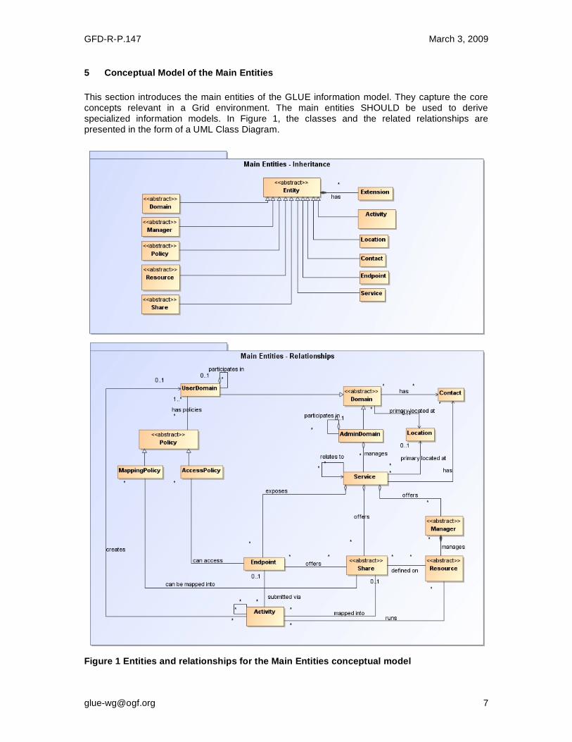
5 Conceptual Model of the Main Entities
This section introduces the main entities of the GLUE information model. They capture the core concepts relevant in a Grid environment. The main entities SHOULD be used to derive specialized information models. In Figure 1, the classes and the related relationships are presented in the form of a UML Class Diagram.
Figure 1 Entities and relationships for the Main Entities conceptual model

GFD-R-P.147 March 3, 2009
5.1 Entity
The Entity class is the root entity from which all the GLUE classes inherit (an exception is
made for the Extension class). The specialized classes will inherit both the associations and
the attributes of Extension class. The attributes CreationTime and Validity are metadata related
to the generation and life of the information. The Name attribute allows a human-readable name to be provided for any object, usable for e.g. monitoring or diagnostic displays. The Name SHOULD NOT have any semantic interpretation. Entity Inherits from Description
Entity <<abstract>>
Abstract root concept from which all the other concepts are derived (except the Extension
class); it has metadata about information creation
and validity plus a key-value pair extension mechanism.
Attribute Type Mult. Unit Description
CreationTime DateTime_t 0..1 Timestamp describing when the entity instance was generated.
Validity UInt64 0..1 s The duration after CreationTime that the information presented in the Entity SHOULD be considered relevant. After that period has elapsed, the information SHOULD NOT be considered
relevant.
ID [key] URI 1 A global unique ID.
Name String 0..1 A human-readable name.
OtherInfo String * Placeholder to publish information that does not fit in any other attribute. Free-form string, comma-
separated tags, (name, value) pairs are all examples of valid syntax.
Association End Mult. Description
Extension.Key * The entity MAY be associated to zero or more key-value pairs.
5.2 Extension
The Extension class provides a general mechanism to add key/value pairs to GLUE classes
when suitable specific attributes are not present. The creation time and validity of each
Extension instance are those of the extended class instance. Entity Inherits from Description
Extension A key/value pair enabling the association of extra information not captured by the model with an Entity instance.
Attribute Type Mult. Unit Description
LocalID LocalID_t 1 An identifier unique within the class instance to which it is
associated
Key String 1 An identifier local to the container class instance; typically an attribute name not present in the model. This identifier
is not required to be unique; several instances of this class MAY hold the same value for this attribute.
Value String 1 A value for the attribute named by the Key.
Association End Mult. Description
Entity 1 The key/value pair is associated to an Entity instance.
5.3 Location The Location class is introduced to model geographical locations where a certain Domain or
Service are placed. The aim is to provide a simple way to express geographical information,
and it is not intended to be used in complex geographical information systems. Due to different requirements, the granularity is not strictly defined and is left to the information producers depending on their needs. Hence the extent of a geographical location can vary from an exact position to a region spanning several different countries, not necessarily adjacent. The accuracy
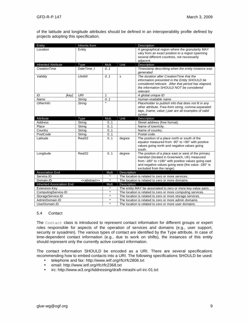
GFD-R-P.147 March 3, 2009
of the latitude and longitude attributes should be defined in an interoperability profile defined by projects adopting this specification. Entity Inherits from Description
Location Entity A geographical region where the granularity MAY vary from an exact position to a region spanning
several different countries, not necessarily adjacent.
Inherited Attribute Type Mult. Unit Description
CreationTime DateTime_t 0..1 Timestamp describing when the entity instance was generated
Validity UInt64 0..1 s The duration after CreationTime that the information presented in the Entity SHOULD be considered relevant. After that period has elapsed,
the information SHOULD NOT be considered relevant
ID [key] URI 1 A global unique ID
Name String 0..1 Human-readable name
OtherInfo String * Placeholder to publish info that does not fit in any
other attribute. Free-form string, comma-separated tags, (name, value ) pair are all examples of valid syntax
Attribute Type Mult. Unit Description
Address String 0..1 Street address (free format).
Place String 0..1 Name of town/city.
Country String 0..1 Name of country.
PostCode String 0..1 Postal code.
Latitude Real32 0..1 degree The position of a place north or south of the equator measured from -90° to +90° with positive values going north and negative values going
south.
Longitude Real32 0..1 degree The position of a place east or west of the primary meridian (located in Greenwich, UK) measured
from -180° to +180° with positive values going east and negative values going west (the value -180° is excluded from the range).
Association End Mult. Description
Service.ID * The location is related to zero or more services.
Domain.ID <<abstract>> * The location is related to zero or more domains.
Inherited Association End Mult. Description
Extension.Key * The entity MAY be associated to zero or more key-value pairs.
ComputingService.ID * The location is related to zero or more computing services.
StorageService.ID * The location is related to zero or more storage services.
AdminDomain.ID * The location is related to zero or more admin domains.
UserDomain.ID * The location is related to zero or more user domains.
5.4 Contact The Contact class is introduced to represent contact information for different groups or expert
roles responsible for aspects of the operation of services and domains (e.g., user support, security or sysadmin). The various types of contact are identified by the Type attribute. In case of time-dependent contact information (e.g., due to work on shifts), the instances of this entity should represent only the currently active contact information. The contact information SHOULD be encoded as a URI. There are several specifications recommending how to embed contacts into a URI. The following specifications SHOULD be used:
• telephone and fax: http://www.ietf.org/rfc/rfc2806.txt • email: http://www.ietf.org/rfc/rfc2368.txt • irc: http://www.w3.org/Addressing/draft-mirashi-url-irc-01.txt

GFD-R-P.147 March 3, 2009
Entity Inherits from Description
Contact Entity Information enabling the establishment of
communication with a person or group of persons related to a Domain.
Inherited Attribute Type Mult. Unit Description
CreationTime DateTime_t 0..1 Timestamp describing when the entity instance was generated
Validity UInt64 0..1 s The duration after CreationTime that the information presented in the Entity SHOULD be considered relevant. After that period has
elapsed, the information SHOULD NOT be considered relevant
ID [key] URI 1 A global unique ID
Name String 0..1 Human-readable name
OtherInfo String * Placeholder to publish info that does not fit in any other attribute. Free-form string, comma-separated tags, (name, value ) pair are all
examples of valid syntax
Attribute Type Mult. Unit Description
Detail URI 1 URI embedding the contact information. The
syntax of the URI depends on the nature of the communication channel.
Type ContactType_t 1 Type of contact.
Association End Mult. Description
Service.ID * The contact is related to zero or more services
Domain.ID <<abstract>> * The contact is related to zero or more domains
Inherited Association End Mult. Description
Extension.Key * The entity MAY be associated to zero or more key-value pairs
ComputingService.ID * The contact is related to zero or more computing services
StorageService.ID * The contact is related to zero or more storage services
AdminDomain.ID * The contact is related to zero or more admin domains
UserDomain.ID * The contact is related to zero or more user domains
5.5 Domain
The Domain class is introduced to model and identify groups of actors that MAY play roles in a
Grid system. It is an abstract entity that MUST NOT be instantiated; it SHOULD be used in order to derive specialized entities. Entity Inherits from Description
Domain <<abstract>>
Entity A collection of actors that MAY be assigned with roles and privileges associated with Entities via Policies. A Domain
MAY have relationships to other domains.
Inherited Attribute Type Mult
.
Unit Description
CreationTime DateTime_t 0..1 Timestamp describing when the entity instance was generated
Validity UInt64 0..1 s The duration after CreationTime that the information presented in the Entity SHOULD be considered relevant. After that period has elapsed,
the information SHOULD NOT be considered relevant
ID [key] URI 1 A global unique ID
Name String 0..1 Human-readable name
OtherInfo String * Placeholder to publish info that does not fit in any other attribute. Free-form string, comma-separated tags, (name,
value ) pair are all examples of valid syntax
Attribute Type Mult.
Unit Description
Description String 0..1 A description of the domain (free format).
WWW URL * A URL identifying a web page with more information about the domain.
Association End Mult.
Description
Contact.ID * A domain MAY be contacted via zero or more contacts.
Location.ID 0..1 A domain is primarily located at one location.

GFD-R-P.147 March 3, 2009
Association End Mult.
Description
Extension.Key * The entity MAY be associated to zero or more key-value pairs.
5.5.1 AdminDomain
The AdminDomain class is introduced to model a collection of actors that manage a number of
services. An AdminDomain MAY be associated to both Contact and Location class instances
in order to provide contact information and geographical location respectively. An AdminDomain
MAY be composed by other AdminDomains in a hierarchical structure. This structure MAY
represent a “participates in” association. Entity Inherits from Description
AdminDomain Domain A collection of actors that MAY be assigned administrative roles and privileges over services via policies. An AdminDomain manages services
that MAY be geographically distributed, but nevertheless a primary location should be identified.
Inherited Attribute Type Mult. Unit Description
CreationTime DateTime_t 0..1 Timestamp describing when the entity instance was generated
Validity UInt64 0..1 s The duration after CreationTime that the information presented in the Entity SHOULD be
considered relevant. After that period has elapsed, the information SHOULD NOT be considered relevant
ID [key] URI 1 A global unique ID
Name String 0..1 Human-readable name
OtherInfo String * Placeholder to publish info that does not fit in any other attribute. Free-form string, comma-separated tags, (name, value ) pair are all
examples of valid syntax
Description String 0..1 A description of the domain
WWW URI * The URL identifying a web page with more information about the domain
Attribute Type Mult. Unit Description
Distributed ExtendedBoolean_t 0..1 True if the services managed by the AdminDomain are considered geographically distributed by the administrators themselves.
Owner String * Identification of a person or legal entity which pays for the services and resources (no particular format is defined).
Association End Mult. Description
Service.ID * An AdminDomain manages zero or more Services.
AdminDomain.ID * An AdminDomain aggregates zero or more AdminDomains.
AdminDomain.ID 0..1 An AdminDomain participates in another AdminDomain.
Inherited Association End Mult. Description
Extension.Key * The entity MAY be extended via key-value pairs.
ComputingService.ID * An AdminDomain manages zero or more Computing
Services.
StorageService.ID * An AdminDomain manages zero or more Storage Services.
Contact.ID * A domain MAY be contacted via zero or more contacts.
Location.ID 0..1 A domain is primary located at one location.
5.5.2 UserDomain
The UserDomain class SHOULD be used to capture the concept of a Virtual Organization (VO).
By VO, we mean a set of individuals and/or institutions having direct access to computers, software, data, and other resources for collaborative problem-solving or other purposes. Resources utilized by a VO are expected to be accessible via network endpoints and constrained

GFD-R-P.147 March 3, 2009
by defined utilization targets called shares. The VO MAY exhibit its internal structure in terms of
groups of individuals, each of them constituting a UserDomain. UserDomains MAY be
hierarchically structured. The “participates in” association MAY represent this structure. Entity Inherits from Description
UserDomain Domain A collection of actors that MAY be assigned with user roles and privileges to services or shares via policies.
Inherited Attribute Type Mult. Unit Description
CreationTime DateTime_t 0..1 Timestamp describing when the entity instance
was generated
Validity UInt64 0..1 s The duration after CreationTime that the information presented in the Entity SHOULD be
considered relevant. After that period has elapsed, the information SHOULD NOT be considered
relevant
ID [key] URI 1 A global unique ID
Name String 0..1 Human-readable name
OtherInfo String * Placeholder to publish info that does not fit in any other attribute. Free-form string, comma-
separated tags, (name, value ) pair are all examples of valid syntax
Description String 0..1 A description of the domain
WWW URI * The URL identifying a web page with more information about the domain
Attribute Type Mult. Unit Description
Level UInt32 0..1 The number of hops to reach the root for hierarchically organized domains described by
the “composed by” association (0 is for the root).
UserManager URI * An Endpoint ID for the endpoint of a service managing the association of users with the
domain, and related attributes such as groups or roles.
Member String * An identifier for a user in this user domain.
Association End Mult. Description
Policy.ID <<abstract>> * A User Domain has associated zero or more policies.
UserDomain.ID * A User Domain aggregates zero or more User Domains.
UserDomain.ID 0..1 An User Domain participates in another User Domain.
Inherited Association End Mult. Description
Extension.Key * The entity MAY be extended via key-value pairs.
Contact.ID * The domain MAY be contacted via zero or more contacts.
Location.ID 0..1 A domain is primary located at one location.
AccessPolicy.ID * A User Domain has associated zero or more access policies.
MappingPolicy.ID * A User Domain has associated zero or more mapping policies.
As regards the UserManager attribute, it is RECOMMENDED that its value is an Endpoint ID enabling discovery of the related Service class instance and associated attributes. An example
of a User Manager would be an endpoint for a VOMS (Virtual Organization Membership Service, http://voms.forge.cnaf.infn.it/) server. 5.6 Service One of the main goals of the GLUE information model is to enable the discovery of the Grid capabilities available in a certain infrastructure. Based on the use cases and modeling
experience, a number of concepts were identified as general building blocks: Endpoint, Share,
Manager, Resource. The Service class enables the unique identification of instances of
these concepts participating in the provision of some unified capability. The Service class
SHOULD be also used to characterize this overall capability.

GFD-R-P.147 March 3, 2009
Entity Inherits from Description
Service Entity An abstracted, logical view of actual software components that participate in the creation of
an entity providing one or more functionalities useful in a Grid environment. A service exposes zero or more Endpoints
having well-defined interfaces, zero or more Shares and zero or more Managers and the related Resources. The Service is
autonomous and denotes a weak aggregation among Endpoints, the underlying Managers and the related
Resources, and the defined Shares. The Service enables the identification of this whole set of entities providing the
functionality with a persistent name.
Inherited Attribute Type Mult. Unit Description
CreationTime DateTime_t 0..1 Timestamp describing when the entity
instance was generated
Validity UInt64 0..1 s The duration after CreationTime that the information presented in the Entity SHOULD
be considered relevant. After that period has elapsed, the information SHOULD NOT be
considered relevant
ID [key] URI 1 A global unique ID
Name String 0..1 Human-readable name
OtherInfo String * Placeholder to publish info that does not fit in any other attribute. Free-form string, comma-separated tags, (name, value ) pair are all examples of valid syntax
Attribute Type Mult. Unit Description
Capability Capability_t * The provided capabilities according to the Open Grid Service Architecture (OGSA)
architecture [OGF-GFD80] (this is the union of all values assigned to the Capability attribute of the Endpoints which form part of
this service).
Type ServiceType_t 1 The type of service according to a namespace-based classification (the
namespace MAY be related to a middleware name, an organization or other concepts; org.ogf.glue.* is reserved for Types defined
by the OGF GLUE Working Group).
QualityLevel QualityLevel_t 1 The maturity of the Service in terms of the
quality of the underlying software components; the value corresponds to the highest QualityLevel among the available
Endpoints.
StatusInfo URL * A URL specifying a web page providing additional information, for example
monitoring of the underlying services.
Complexity String 0..1 A human-readable summary description of the complexity in terms of the number of
endpoint types, shares and resources. The syntax should be: endpointType=X, share=Y, resource=Z.
Association End Mult. Description
Endpoint.ID * A service exposes zero or more endpoints.
Share.ID <<abstract>> * A service offers zero or more shares.
Manager.ID <<abstract>> * A service offers zero or more managers.
Contact.ID * A service has zero or more contacts.
Location.ID 0..1 A service is primary located at a location.
Service.ID * A service is related to zero or more services.
Service.ID * A service is related to zero or more services.
Inherited Association End Mult. Description
Extension.Key * The entity MAY be extended via key-value pairs.

GFD-R-P.147 March 3, 2009
A simple Service aggregates an Endpoint, no Share, no Manager and no Resource (e.g., a
metadata catalogue service). In the context of a Service class, the same Resource MAY be
exposed via multiple Endpoints based on the defined Shares. For instance, in the area of
storage systems, two Endpoints implementing SRMv1 [SRMV1] and SRMv2.2 [SRMV2]
interfaces respectively MAY expose the same Resource via different Endpoints offering
different interface versions; in the area of computing systems, the CREAM [cream] and GRAM
[GRAM] Endpoints MAY expose the Resources locally managed by the same Manager
(typically a batch system). Endpoints, Shares, Managers and Resources MUST belong to
precisely one Service. 5.7 Endpoint
The Endpoint class models a network location that can be contacted to access certain
functionalities based on a well-defined interface. The defined attributes refer to aspects such as the network location, the exposed interface name and version, the details of the implementation, the functional state and the scheduled downtime. Entity Inherits from Description
Endpoint Entity A network location having a well-defined
interface and exposing specific service functionalities.
Inherited Attribute Type Mult. Unit Description
CreationTime DateTime_t 0..1 Timestamp describing when the entity instance was generated
Validity UInt64 0..1 s The duration after CreationTime that the information presented in the Entity SHOULD be considered relevant. After
that period has elapsed, the information SHOULD NOT be considered relevant
ID [key] URI 1 A global unique ID
Name String 0..1 Human-readable name
OtherInfo String * Placeholder to publish info that does not fit in any other attribute. Free-form string, comma-separated tags, (name, value ) pair are all examples of valid syntax
Attribute Type Mult. Unit
URL URL 1 Network location of an endpoint,which
enables a specific component of the Service to be contacted.
Capability Capability_t * The provided capability according to the
OGSA architecture classification.
Technology EndpointTechnology_t 0..1 The technology used to implement the endpoint interface.
InterfaceName InterfaceName_t 1 The identification name of the primary protocol supported by the endpoint
interface.
InterfaceVersion String 0..* The version of the primary interface protocol (free format).
InterfaceExtension URI * The identification of an extension to the interface protocol supported by the Endpoint.
WSDL URL * The URL of a WSDL document describing the offered interface (this applies only to Web Services endpoints).
SupportedProfile URI * A URI identifying a supported profile for the Endpoint interface.
Semantics URL * The URl of a document providing a human-readable description of the semantics of the Endpoint functionalities
(e.g. a software manual).
Implementor String 0..1 The name of the main organization implementing this software component
(free format, but the chosen names

GFD-R-P.147 March 3, 2009
SHOULD be clearly identifiable with the organisation).
ImplementationName String 0..1 The name of the implementation (as defined by the Implementor).
ImplementationVersion String 0..1 The version of the implementation (the
syntax is defined by the Implementor, but MAY be: major.minor.patch).
QualityLevel QualityLevel_t 1 The maturity of the endpoint in terms of the quality of the software components which implement it.
HealthState EndpointHealthState_t 1 A state representing the current health of the Endpoint in terms of its ability to properly deliver the expected
functionality.
HealthStateInfo String 0..1 A human-readable explanation of the HealthState of the Endpoint (free
format).
ServingState ServingState_t 1 A state specifying whether the Endpoint is currently accepting new requests, and
whether it is currently servicing requests which have already been accepted.
StartTime DateTime_t 0..1 The timestamp of the start time of the service underlying the Endpoint.
IssuerCA DN_t 0..1 The Distinguished Name of the
Certification Authority issuing the host/service certificate presented by the Endpoint.
TrustedCA DN_t * The Distinguished Name of a trusted Certification Authority (CA); i.e., certificates issued by the CA are
accepted by the authentication process. Alternatively this may identify a standard bundle of accepted CAs, e.g. those
accredited by the IGTF. Note that this does not imply that such certificates will be authorized to use the Endpoint.
DowntimeAnnounce DateTime_t 0..1 The timestamp for an announcement of the next scheduled downtime.
DowntimfeStart DateTime_t 0..1 A timestamp describing when the next
downtime is scheduled to start.
DowntimeEnd DateTime_t 0..1 A timestamp describing when the next
downtime is scheduled to end.
DowntimeInfo String 0..1 A human-readable description of the next scheduled downtime (free format).
Association End Mult. Description
Service.ID 1 An endpoint is part of a Service.
Share.ID <<abstract>> * An endpoint MAY pass activities to zero or more Shares.
AccessPolicy.ID * An endpoint has associated zero or more
AccessPolicies.
Activity.ID * An endpoint has accepted and is managing zero or more Activities.
Inherited Association End Mult. Description
Extension.Key * The entity MAY be extended via key-value pairs.
For Grid services requiring a richer set of attributes for the Endpoint, specific models MAY be
derived by specializing from the Endpoint class and adding new properties or relationships. The
current proposal contains the ComputingEndpoint specialization (see Section 6.2) and the
StorageEndpoint specialization (see Section 7.4).
The network location of an endpoint MUST be encoded in a URI. When available, standard schemes for the encoding SHOULD be used (e.g., as used for the Java Messaging Service http://www.ietf.org/internet-drafts/draft-merrick-jms-uri-03.txt).
GFD-R-P.147 March 3, 2009
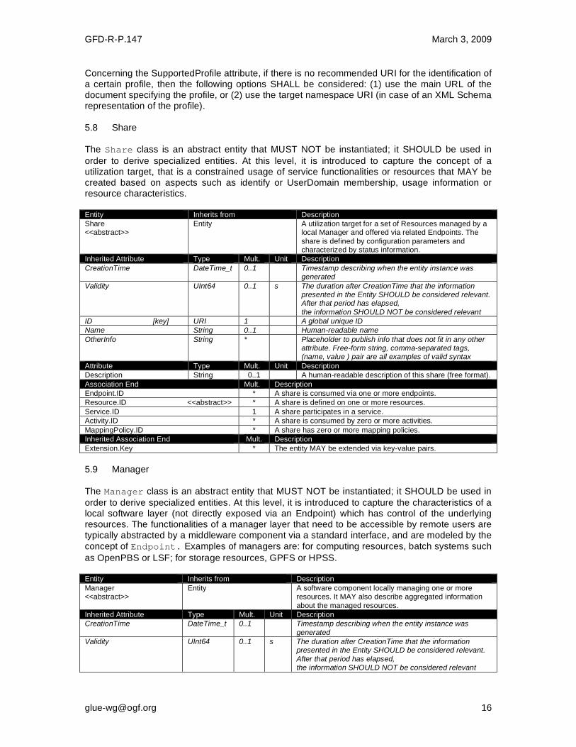
Concerning the SupportedProfile attribute, if there is no recommended URI for the identification of a certain profile, then the following options SHALL be considered: (1) use the main URL of the document specifying the profile, or (2) use the target namespace URI (in case of an XML Schema representation of the profile). 5.8 Share
The Share class is an abstract entity that MUST NOT be instantiated; it SHOULD be used in
order to derive specialized entities. At this level, it is introduced to capture the concept of a utilization target, that is a constrained usage of service functionalities or resources that MAY be created based on aspects such as identify or UserDomain membership, usage information or resource characteristics. Entity Inherits from Description
Share <<abstract>>
Entity A utilization target for a set of Resources managed by a local Manager and offered via related Endpoints. The
share is defined by configuration parameters and characterized by status information.
Inherited Attribute Type Mult. Unit Description
CreationTime DateTime_t 0..1 Timestamp describing when the entity instance was generated
Validity UInt64 0..1 s The duration after CreationTime that the information presented in the Entity SHOULD be considered relevant. After that period has elapsed,
the information SHOULD NOT be considered relevant
ID [key] URI 1 A global unique ID
Name String 0..1 Human-readable name
OtherInfo String * Placeholder to publish info that does not fit in any other attribute. Free-form string, comma-separated tags, (name, value ) pair are all examples of valid syntax
Attribute Type Mult. Unit Description
Description String 0..1 A human-readable description of this share (free format).
Association End Mult. Description
Endpoint.ID * A share is consumed via one or more endpoints.
Resource.ID <<abstract>> * A share is defined on one or more resources.
Service.ID 1 A share participates in a service.
Activity.ID * A share is consumed by zero or more activities.
MappingPolicy.ID * A share has zero or more mapping policies.
Inherited Association End Mult. Description
Extension.Key * The entity MAY be extended via key-value pairs.
5.9 Manager
The Manager class is an abstract entity that MUST NOT be instantiated; it SHOULD be used in
order to derive specialized entities. At this level, it is introduced to capture the characteristics of a local software layer (not directly exposed via an Endpoint) which has control of the underlying resources. The functionalities of a manager layer that need to be accessible by remote users are typically abstracted by a middleware component via a standard interface, and are modeled by the
concept of Endpoint. Examples of managers are: for computing resources, batch systems such
as OpenPBS or LSF; for storage resources, GPFS or HPSS. Entity Inherits from Description
Manager <<abstract>>
Entity A software component locally managing one or more resources. It MAY also describe aggregated information
about the managed resources.
Inherited Attribute Type Mult. Unit Description
CreationTime DateTime_t 0..1 Timestamp describing when the entity instance was
generated
Validity UInt64 0..1 s The duration after CreationTime that the information presented in the Entity SHOULD be considered relevant.
After that period has elapsed, the information SHOULD NOT be considered relevant

GFD-R-P.147 March 3, 2009
ID [key] URI 1 A global unique ID
Name String 0..1 Human-readable name
OtherInfo String * Placeholder to publish info that does not fit in any other attribute. Free-form string, comma-separated tags, (name, value ) pair are all examples of valid syntax
Attribute Type Mult. Unit
ProductName String 1 The name of the software product which implements the
Manager functionality. The attribute is free format, but SHOULD correspond to the standard name by which the product is generally known.
ProductVersion String 0..1 The version of the software product which implements the Manager functionality. The attribute is free format, but SHOULD correspond to the primary version as defined by
the software provider.
Association End Mult. Description
Service.ID 1 A manager participates in a service.
Resource.ID <<abstract>> 1..* A manager manages zero or more resources.
Inherited Association End Mult. Description
Extension.Key * The entity MAY be extended via key-value pairs.
5.10 Resource
The Resource class is an abstract entity that MUST NOT be instantiated; it SHOULD be used in
order to derive specialized entities. It is introduced to identify and model hardware entities
providing capabilities which are exposed via Endpoints. Examples are execution environments
for computational activities or data stores for data. Entity Inherits from Description
Resource
<<abstract>>
Entity An entity providing a capability or capacity, managed by a
local software component (Manager), part of a logical Service, reachable via one or more Endpoints and having one or more Shares defined on it. A Resource MAY refer
to a specified category of hardware, with summary information on the available resources in that category.
Inherited Attribute Type Mult. Unit Description
CreationTime DateTime_t 0..1 Timestamp describing when the entity instance was generated
Validity UInt64 0..1 s The duration after CreationTime that the information presented in the Entity SHOULD be considered relevant. After that period has elapsed,
the information SHOULD NOT be considered relevant
ID [key] URI 1 A global unique ID
Name String 0..1 Human-readable name
OtherInfo String * Placeholder to publish info that does not fit in any other attribute. Free-form string, comma-separated tags, (name, value ) pair are all examples of valid syntax
Attribute Type Mult. Unit Description
No extra properties are defined in the specialized entity
Association End Mult. Description
Manager.ID <<abstract>> 1 A resource is managed by a manager.
Share.ID <<abstract>> * A resource provides capacity in terms of shares.
Activity.ID * A resource runs zero or more activities.
Inherited Association End Mult. Description
Extension.Key * The entity MAY be extended via key-value pairs.
5.11 Activity
The Activity class models units of work which are submitted to Services via Endpoints.
Grid jobs, i.e. Computing Activities in GLUE, are example of Activities for a Computing
Service. An interesting type of relationship for jobs derives from their propagation through several
Services. For instance, a broker Service submits a Grid job to a selected execution
Service; upon completion the execution Service submits a logging record to an accounting
Service. Each of these Services may have associated an instance of a Grid Activity

GFD-R-P.147 March 3, 2009
related to the lifecycle of the job within the service. All instances refer to the same conceptual job submitted by the user. Entity Inherits from Description
Activity Entity An Activity is a unit of work managed by a Service and submitted via an Endpoint; when accepted by the
Endpoint, than it MAY be mapped to a Share and MAY be executed by a local Manager via one or more Resources. An Activity MAY have relationships to other
Activities being managed by different Services, in which case it shares a common context.
Inherited Attribute Type Mult. Unit Description
CreationTime DateTime_t 0..1 Timestamp describing when the entity instance was generated
Validity UInt64 0..1 s The duration after CreationTime that the information presented in the Entity SHOULD be considered relevant. After that period has elapsed,
the information SHOULD NOT be considered relevant
ID [key] URI 1 A global unique ID
Name String 0..1 Human-readable name
OtherInfo String * Placeholder to publish info that does not fit in any other attribute. Free-form string, comma-separated tags,
(name, value ) pair are all examples of valid syntax
Attribute Type Mult. Unit Description
No extra properties are
defined in the specialized entity
Association End Mult. Description
UserDomain.ID 0..1 An activity is managed by a user domain.
Endpoint.ID 0..1 An activity is submitted to an endpoint.
Share.ID <<abstract>> 0..1 An activity is mapped into a share.
Resource.ID <<abstract>> 0..1 An activity is executed in a resource.
Activity.ID * An activity is related to zero or more activities.
Activity.ID * An activity is related to zero or more activities.
Inherited Association End Mult. Description
Extension.Key * The entity MAY be extended via key-value pairs.
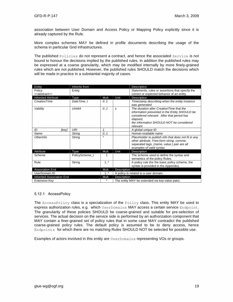
5.12 Policy
The Policy class is an abstract entity that MUST NOT be instantiated; it SHOULD be used in
order to derive specialized entities. This class is introduced to model statements, rules or assertions that define the correct or expected behavior of entities. Two specializations are
introduced: AccessPolicy related to Endpoints and MappingPolicy related to Shares.
For a given entity to which policies are associated (i.e., Endpoint and AccessPolicy, Share
and MappingPolicy), several instances of the Policy class MAY be defined. This is allowed in
order to enable the advertisement of policies using different schemes. We RECOMMEND that only one instance per policy scheme is associated to the same entity instance. The evaluation algorithm for the rules SHOULD be defined by the policy scheme.
If an entity instance is associated to different Policy instances, each of them based on a
different scheme, then the evaluation process SHOULD consider each set of policies independently. This means that the evaluation SHOULD rely on a certain policy scheme which is selected and understood by the consumer, and not by composing policies expressed using different schemes. In this document, we provide the definition for a “basic” scheme (see Appendix B.4). Such a scheme is designed to be simple and is inspired by real world scenarios in current production Grid systems. The Rule attribute implicitly contains a reference to the associated User Domains; therefore, in the concrete data model mapping, we RECOMMEND to not represent the
GFD-R-P.147 March 3, 2009
association between User Domain and Access Policy or Mapping Policy explicitly since it is already captured by the Rule. More complex schemes MAY be defined in profile documents describing the usage of the schema in particular Grid infrastructures. The published Policies do not represent a contract, and hence the associated Service is not
bound to honour the decisions implied by the published rules. In addition the published rules may be expressed at a coarse granularity, which may be modified internally by more finely-grained rules which are not published. However, the published rules SHOULD match the decisions which will be made in practice in a substantial majority of cases. Entity Inherits from Description
Policy <<abstract>>
Entity Statements, rules or assertions that specify the correct or expected behavior of an entity.
Inherited Attribute Type Mult. Unit Description
CreationTime DateTime_t 0..1 Timestamp describing when the entity instance was generated
Validity UInt64 0..1 s The duration after CreationTime that the information presented in the Entity SHOULD be
considered relevant. After that period has elapsed, the information SHOULD NOT be considered
relevant
ID [key] URI 1 A global unique ID
Name String 0..1 Human-readable name
OtherInfo String * Placeholder to publish info that does not fit in any other attribute. Free-form string, comma-separated tags, (name, value ) pair are all
examples of valid syntax
Attribute Type Mult. Unit Description
Scheme PolicyScheme_t 1 The scheme used to define the syntax and semantics of the policy Rules.
Rule String 1..* A policy rule (for the basic policy scheme, the
syntax is provided in the Appendix).
Association End Mult. Description
UserDomain.ID 1..* A policy is related to a user domain.
Inherited Association End Mult. Description
Extension.Key * The entity MAY be extended via key-value pairs.
5.12.1 AccessPolicy
The AccessPolicy class is a specialization of the Policy class. This entity MAY be used to
express authorization rules, e.g. which UserDomains MAY access a certain service Endpoint.
The granularity of these policies SHOULD be coarse-grained and suitable for pre-selection of services. The actual decision on the service side is performed by an authorization component that MAY contain a finer-grained set of policy rules that in some case MAY contradict the published coarse-grained policy rules. The default policy is assumed to be to deny access, hence
Endpoints for which there are no matching Rules SHOULD NOT be selected for possible use.
Examples of actors involved in this entity are UserDomains representing VOs or groups.

GFD-R-P.147 March 3, 2009
Entity Inherits from Description
AccessPolicy Policy Statements, rules or assertions that provide
coarse-granularity information about the authorization of access by groups of actors to an Endpoint.
Inherited Attribute Type Mult Unit Description
CreationTime DateTime_t 0..1 Timestamp describing when the entity instance
was generated
Validity UInt64 0..1 s The duration after CreationTime that the information presented in the Entity SHOULD be
considered relevant. After that period has elapsed, the information SHOULD NOT be considered
relevant
ID [key] URI 1 A global unique ID
Name String 0..1 Human-readable name
OtherInfo String * Placeholder to publish info that does not fit in any other attribute. Free-form string, comma-
separated tags, (name, value ) pair are all examples of valid syntax
Scheme PolicyScheme_t 1 Scheme adopted to define the policy rules
Rule PolicyRule_t 1..* A policy rule (for the basic policy scheme, syntax is provide in the Appendix)
Attribute Type Mult. Unit Description
No extra properties are defined in the specialized entity.
Association End Mult. Description
Endpoint.ID 1 An access policy is related to an endpoint.
Inherited Association End Mult. Description
Extension.Key * The entity MAY be extended via key-value pairs.
UserDomain.ID 1..* An access policy is related to a user domain.
5.12.2 MappingPolicy
The MappingPolicy class is a specialization of the Policy class. This entity MAY be used to
express which UserDomains MAY consume a certain share of resources. The granularity of
these policies SHOULD be coarse-grained and suitable for pre-selection of services. The actual decision on the service side is performed by an authorization component that MAY contain a finer-grained set of policy rules that in some case MAY contradict the published coarse-grained policy rules.
Conceptually, the union of all the MappingPolicy rules should match the corresponding
AccessPolicy rules, i.e. any authorised UserDomain will be mapped to at least one Share.
However, publication of Shares is OPTIONAL, and hence there MAY be no Share with a
matching MappingPolicy rule. In this case a consumer SHOULD NOT make any assumption
about the properties of the Share to which it will be mapped. Conversely, the published
MappingPolicy rules MAY not have a corresponding AccessPolicy, in which case the
implication is that there is some unpublished access method enabling access to the associated Share.
When evaluating the mapping to a certain Share using the algorithm implied by the policy
scheme, if multiple solutions are available then the consumer SHOULD NOT make any
assumption about which Share will be assigned to its Activity, and if it requires a specific
Share it SHOULD request that Share explicitly.

GFD-R-P.147 March 3, 2009
Entity Inherits from Description
MappingPolicy Policy Statements, rules or assertions that provide
coarse-granularity information about the mapping of User Domain requests to a Share.
Inherited Attribute Type Mult Unit Description
CreationTime DateTime_t 0..1 Timestamp describing when the entity instance was generated
Validity UInt64 0..1 s The duration after CreationTime that the information presented in the Entity SHOULD be considered relevant. After that period has
elapsed, the information SHOULD NOT be considered relevant
ID [key] URI 1 A global unique ID
Name String 0..1 Human-readable name
OtherInfo String * Placeholder to publish info that does not fit in any other attribute. Free-form string, comma-separated tags, (name, value ) pair are all
examples of valid syntax
Scheme PolicyScheme_t 1 Scheme adopted to define the policy rules
Rule PolicyRule_t 1..* A policy rule (for the basic policy scheme, syntax
is provide in the Appendix)
Attribute Type Mult. Unit Description
No extra properties are defined in the specialized entity.
Association End Mult. Description
Share.ID <<abstract>> 1 A mapping policy is related to a share.
Inherited Association End Mult. Description
Extension.Key * The entity MAY be extended via key-value pairs.
UserDomain.ID 1..* An access policy is related to a user domain.

GFD-R-P.147 March 3, 2009
6 Conceptual Model of the Computing Service
The conceptual model of the Computing Service is based on the main entities and uses
specializations of the Service, Endpoint, Share, Manager, Resource, and Activity
entities. Further computing related concepts such as Application Environment,
Application Handle and Benchmark are introduced.
Figure 2 Entities and relationships for the Computing Service conceptual model
In this section, we extensively use the concepts of physical CPU, logical CPU and slot defined as follows:
• a physical CPU is defined by a socket on a motherboard, i.e. there is one physical CPU per socket (e.g., a multi-core CPU counts as one physical CPU);
• a logical CPU corresponds to a CPU as visible by the operating system running either on a real or virtual machine (e.g. a four-core CPU counts as four logical CPUs);
• a slot is a portion of executable time in a logical CPU offered by an execution environment instance which MAY be occupied by a job:
o typically there is one slot per logical CPU, but a logical CPU MAY be shared among multiple slots;

GFD-R-P.147 March 3, 2009
o jobs MAY occupy several slots at the same time (e.g., MPI jobs); a multi-slot job
is counted as one Activity.
Throughout the specification, we also use the concept of storage extent to mean the capabilities and management of the various media that exist to store data and allow data retrieval. 6.1 ComputingService
The ComputingService class is a specialization of the Service class for a service offering
computational capacity. The ComputingService entity is the main logical unit, and aggregation
point for several entities together modeling a computing capability in a Grid system. A
ComputingService is capable of executing ComputingActivities on its associated
resources. The resources behind the ComputingService are described via the
ComputingManager, ExecutionEnvironment, ApplicationEnvironment,
ApplicationHandle and Benchmark entities. The governing policies and status of the
resources are given by the ComputingShare elements. The ComputingActivities of a
ComputingService are submitted and controlled via a ComputingEndpoint.
Entity Inherits from Description
ComputingService Service An abstracted, logical view of software and hardware components that participate in the creation of a
computational capacity in a Grid environment. A Computing Service exposes zero or more Computing Endpoints having well-defined interfaces, zero or more
Computing Shares and zero or more Computing Managers and the related Execution Environments.
The computing service is autonomous and denotes a weak aggregation among Computing Endpoints, the underlying Computing Managers and related Execution
Environments, and the defined Computing Shares. The Computing Service enables the identification of the whole set of entities providing the computing
functionality with a persistent name.
Inherited Attribute Type Mult Unit Description
CreationTime DateTime_t 0..1 Timestamp describing when the entity instance was
generated
Validity UInt64 0..1 s The duration after CreationTime that the information presented in the Entity SHOULD be considered relevant.
After that period has elapsed, the information SHOULD NOT be considered relevant
ID [key] URI 1 A global unique ID
Name String 0..1 Human-readable name
OtherInfo String * Placeholder to publish info that does not fit in any other
attribute. Free-form string, comma-separated tags, (name, value ) pair are all examples of valid syntax
Capability Capability_t * The provided capability according to the Open Grid
Service Architecture (OGSA) architecture [OGF-GFD80] (this is the union of all values assigned to the capability attribute of the endpoints part of this service)
Type ServiceType_t 1 The type of service according to a namespace-based classification (the namespace MAY be related to a middleware name, an organization or other concepts;
org.ogf.glue is reserved for the OGF GLUE Working Group)
QualityLevel QualityLevel_t 1 Maturity of the service in terms of quality of the software components
StatusInfo URI * Web page providing additional information like
monitoring aspects
Complexity String 0..1 Human-readable summary description of the complexity in terms of the number of endpoint types, shares and
resources. The syntax should be: endpointType=X, share=Y, resource=Z.
GFD-R-P.147 March 3, 2009
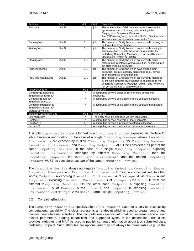
Attribute Type Mult Unit Description
TotalJobs UInt32 0..1 job The total number of Grid jobs currently known to the
system (the sum of RunningJobs, WaitingJobs, StagingJobs, SuspendedJobs and PreLRMSWaitingJobs); this value SHOULD not include
jobs submitted locally rather than via the Grid.
RunningJobs UInt32 0..1 job The number of Grid jobs which are currently running in an Execution Environment.
WaitingJobs UInt32 0..1 job The number of Grid jobs which are currently waiting to start execution. Usually these will be queued in the
underlying Computing Manager (i.e., a Local Resource Managment System or LRMS).
StagingJobs UInt32 0..1 job The number of Grid jobs which are currently either
staging files in before starting execution, or staging files out after finishing execution.
SuspendedJobs UInt32 0..1 job The number of Grid jobs which have started their
execution, but are currently suspended (e.g., having been preempted by another job).
PreLRMSWaitingJobs UInt32 0..1 job The number of Grid jobs which are currently managed
by the Grid software layer waiting to be passed to the underlying Computing Manager (LRMS), and hence are not yet candidates to start execution.
Association End Mult. Description
ComputingEndpoint.ID
[redefines Endpoint.ID]
* A computing service exposes zero or more computing
endpoints.
ComputingShare.ID [redefines Share.ID]
* A computing service offers zero or more computing shares.
ComputingManager.ID [redefines Manager.ID]
* A computing service offers zero or more computing managers.
StorageService.ID
Inherited Association End Mult. Description
Extension.Key * The entity MAY be extended via key-value pairs.
Contact.ID * A computing service has zero or more contacts.
Location.ID 0..1 A computing service is primarily located at a location.
Service.ID * A computing service is related to zero or more services.
A simple Computing Service is formed by a Computing Endpoint exposing an interface for
job submission and control. In the case of a single Computing Manager whose Execution
Environments are exposed by multiple Computing Endpoints, the Computing Manager,
Execution Environments and Computing Endpoints MUST be considered as part of the
same Computing Service. In the case of a single Computing Endpoint exposing
Execution Environments managed by different Computing Managers, then the
Computing Endpoint, the Execution Environments and the related Computing
Managers MUST be considered as part of the same Computing Service.
The Computing Service always aggregates Computing Endpoints, Computing Shares,
Computing Managers and Execution Environments forming a connected set. In other
words, Endpoint A exposing Execution Environment A of Manager A via Share A and
Endpoint B exposing Execution Environment B of Manager B via Share B form two
different Computing Services. On the other hand, Endpoint A exposing Execution
Environment A of Manager A via Share A and Endpoint B exposing Execution
Environment A of Manager A via Share B form a single Computing Service.
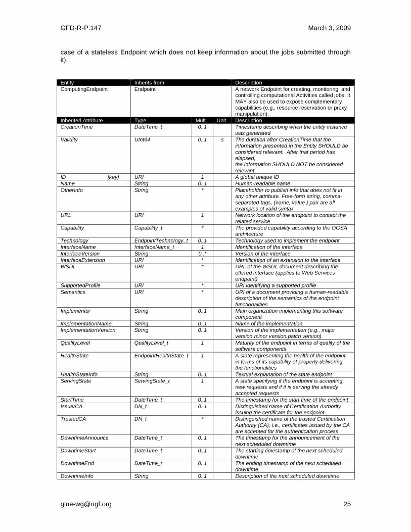
6.2 ComputingEndpoint
The ComputingEndpoint is a specialization of the Endpoint class for a service possessing
computational capability. The class represents an endpoint which is used to create, control and monitor computational activities. The computational-specific information concerns service load related parameters, staging capabilities and supported types of job description. This class provides attributes that MAY be used to publish summary information about jobs submitted via a particular Endpoint. Such attributes are optional and may not always be measurable (e.g., in the
GFD-R-P.147 March 3, 2009
case of a stateless Endpoint which does not keep information about the jobs submitted through it). Entity Inherits from Description
ComputingEndpoint
Endpoint A network Endpoint for creating, monitoring, and controlling computational Activities called jobs. It
MAY also be used to expose complementary capabilities (e.g., resource reservation or proxy manipulation).
Inherited Attribute Type Mult Unit Description
CreationTime DateTime_t 0..1 Timestamp describing when the entity instance
was generated
Validity UInt64 0..1 s The duration after CreationTime that the information presented in the Entity SHOULD be
considered relevant. After that period has elapsed, the information SHOULD NOT be considered
relevant
ID [key] URI 1 A global unique ID
Name String 0..1 Human-readable name
OtherInfo String * Placeholder to publish info that does not fit in any other attribute. Free-form string, comma-
separated tags, (name, value ) pair are all examples of valid syntax
URL URI 1 Network location of the endpoint to contact the
related service
Capability Capability_t * The provided capability according to the OGSA architecture
Technology EndpointTechnology_t 0..1 Technology used to implement the endpoint
InterfaceName InterfaceName_t 1 Identification of the interface
InterfaceVersion String 0..* Version of the interface
InterfaceExtension URI * Identification of an extension to the interface
WSDL URI * URL of the WSDL document describing the
offered interface (applies to Web Services endpoint)
SupportedProfile URI * URI identifying a supported profile
Semantics URI * URI of a document providing a human-readable description of the semantics of the endpoint
functionalities
Implementor String 0..1 Main organization implementing this software component
ImplementationName String 0..1 Name of the implementation
ImplementationVersion String 0..1 Version of the implementation (e.g., major version.minor version.patch version)
QualityLevel QualityLevel_t 1 Maturity of the endpoint in terms of quality of the software components
HealthState EndpointHealthState_t 1 A state representing the health of the endpoint in terms of its capability of properly delivering the functionalities
HealthStateInfo String 0..1 Textual explanation of the state endpoint
ServingState ServingState_t 1 A state specifying if the endpoint is accepting new requests and if it is serving the already
accepted requests
StartTime DateTime_t 0..1 The timestamp for the start time of the endpoint
IssuerCA DN_t 0..1 Distinguished name of Certification Authority issuing the certificate for the endpoint
TrustedCA DN_t * Distinguished name of the trusted Certification
Authority (CA), i.e., certificates issued by the CA are accepted for the authentication process
DowntimeAnnounce DateTime_t 0..1 The timestamp for the announcement of the
next scheduled downtime
DowntimeStart DateTime_t 0..1 The starting timestamp of the next scheduled downtime
DowntimeEnd DateTime_t 0..1 The ending timestamp of the next scheduled downtime
DowntimeInfo String 0..1 Description of the next scheduled downtime
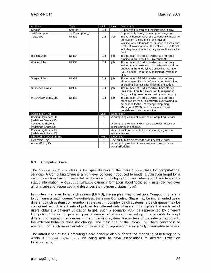
GFD-R-P.147 March 3, 2009
Attribute Type Mult. Unit Description
Staging Staging_t 0..1 Supported file staging functionalities, if any.
JobDescription JobDescription_t * Supported type of job description language.
TotalJobs UInt32 0..1 Job The total number of Grid jobs currently known to
the system (the sum of RunningJobs, WaitingJobs, StagingJobs, SuspendedJobs and PreLRMSWaitingJobs); this value SHOULD not
include jobs submitted locally rather than via the Grid.
RunningJobs UInt32 0..1 job The number of Grid jobs which are currently
running in an Execution Environment.
WaitingJobs UInt32 0..1 job The number of Grid jobs which are currently waiting to start execution. Usually these will be
queued in the underlying Computing Manager (i.e., a Local Resource Managment System or LRMS).
StagingJobs UInt32 0..1 job The number of Grid jobs which are currently either staging files in before starting execution, or staging files out after finishing execution.
SuspendedJobs UInt32 0..1 job The number of Grid jobs which have started their execution, but are currently suspended
(e.g., having been preempted by another job).
PreLRMSWaitingJobs UInt32 0..1 job The number of Grid jobs which are currently managed by the Grid software layer waiting to
be passed to the underlying Computing Manager (LRMS), and hence are not yet candidates to start execution.
Association End Mult. Description
ComputingService.ID [redefines Service.ID]
1 A computing endpoint is part of a Computing Service.
ComputingShare.ID [redefines Share.ID]
* A computing endpoint MAY pass activities to zero or more computing shares.
ComputingActivity.ID [redefines Activity.ID]
* An endpoint has accepted and is managing zero or more Activities.
Inherited Association End Mult. Description
Extension.Key * The entity MAY be extended via key-value pairs.
AccessPolicy.ID * A computing endpoint has assocated zero or more AccessPolicies.
6.3 ComputingShare
The ComputingShare class is the specialization of the main Share class for computational
services. A Computing Share is a high-level concept introduced to model a utilization target for a set of Execution Environments defined by a set of configuration parameters and characterized by
status information. A ComputingShare carries information about "policies" (limits) defined over
all or a subset of resources and describes their dynamic status (load). In clusters managed by a batch system (LRMS), the simplest way to set up a Computing Share is to configure a batch queue. Nevertheless, the same Computing Share may be implemented using different batch system configuration strategies. In complex batch systems, a batch queue may be configured with different sets of policies for different sets of users. This implies that each set of users obtains a different utilization target. Such a scenario MAY be represented by different Computing Shares. In general, given a number of shares to be set up, it is possible to adopt different configuration strategies in the underlying system. Regardless of the selected approach, the external behavior does not change. The main goal of the Computing Share concept is to abstract from such implementation choices and to represent the externally observable behavior. The introduction of the Computing Share concept also supports the modelling of heterogeneity
within a ComputingService by being able to have associations to different Execution
Environments.
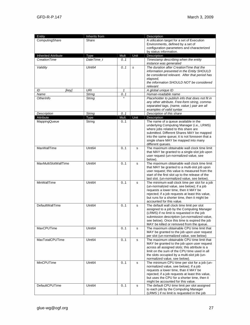
GFD-R-P.147 March 3, 2009
Entity Inherits from Description
ComputingShare
Share A utilization target for a set of Execution
Environments, defined by a set of configuration parameters and characterized by status information.
Inherited Attribute Type Mult Unit Description
CreationTime DateTime_t 0..1 Timestamp describing when the entity instance was generated
Validity UInt64 0..1 s The duration after CreationTime that the information presented in the Entity SHOULD
be considered relevant. After that period has elapsed, the information SHOULD NOT be considered
relevant
ID [key] URI 1 A global unique ID
Name String 0..1 Human-readable name
OtherInfo String * Placeholder to publish info that does not fit in any other attribute. Free-form string, comma-separated tags, (name, value ) pair are all
examples of valid syntax
Description String 0..1 Description of this share
Attribute Type Mult. Unit Description
MappingQueue String 0..1 The name of a queue available in the underlying Computing Manager (i.e., LRMS)
where jobs related to this share are submitted. Different Shares MAY be mapped into the same queue; it is not foreseen that a
single share MAY be mapped into many different queues.
MaxWallTime UInt64 0..1 s The maximum obtainable wall clock time limit
that MAY be granted to a single-slot job upon user request (un-normalized value, see below).
MaxMultiSlotWallTime UInt64 0..1 s The maximum obtainable wall clock time limit that MAY be granted to a multi-slot job upon user request; this value is measured from the
start of the first slot up to the release of the last slot. (un-normalized value, see below).
MinWallTime UInt64 0..1 s The minimum wall clock time per slot for a job (un-normalized value, see below); if a job requests a lower time, then it MAY be
rejected; if a job requests at least this value, but runs for a shorter time, then it might be accounted for this value.
DefaultWallTime UInt64 0..1 s The default wall clock time limit per slot assigned to a job by the Computing Manager (LRMS) if no limit is requested in the job
submission description (un-normalized value, see below). Once this time is expired the job MAY be killed or removed from the queue.
MaxCPUTime UInt64 0..1 s The maximum obtainable CPU time limit that MAY be granted to the job upon user request per slot (un-normalized value, see below)
MaxTotalCPUTime UInt64 0..1 s The maximum obtainable CPU time limit that MAY be granted to the job upon user request across all assigned slots; this attribute is a
limit on the sum of the CPU time used in all the slots occupied by a multi-slot job (un-normalized value, see below).
MinCPUTime UInt64 0..1 s The minimum CPU time per slot for a job (un-normalized value, see below); if a job requests a lower time, than it MAY be
rejected; if a job requests at least this value, but uses the CPU for a shorter time, then it might be accounted for this value.
DefaultCPUTime UInt64 0..1 s The default CPU time limit per slot assigned to each job by the Computing Manager
(LRMS ) if no limit is requested in the job
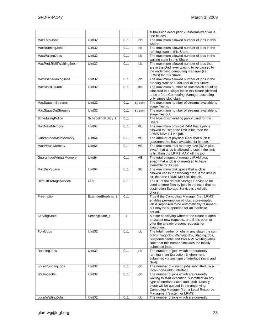
GFD-R-P.147 March 3, 2009
submission description (un-normalized value, see below).
MaxTotalJobs UInt32 0..1 job The maximum allowed number of jobs in this Share.
MaxRunningJobs UInt32 0..1 job The maximum allowed number of jobs in the
running state in this Share.
MaxWaitingJobs UInt32 0..1 job The maximum allowed number of jobs in the
waiting state in this Share.
MaxPreLRMSWaitingJobs UInt32 0..1 job The maximum allowed number of jobs that are in the Grid layer waiting to be passed to
the underlying computing manager (i.e., LRMS) for this Share.
MaxUserRunningJobs UInt32 0..1 job The maximum allowed number of jobs in the
running state per Grid user in this Share.
MaxSlotsPerJob UInt32 0..1 slot The maximum number of slots which could be allocated to a single job in this Share (defined
to be 1 for a Computing Manager accepting only single-slot jobs).
MaxStageInStreams UInt32 0..1 stream The maximum number of streams available to stage files in.
MaxStageOutStreams UInt32 0..1 stream The maximum number of streams available to
stage files out.
SchedulingPolicy SchedulingPolicy_t 0..1 The type of scheduling policy used for the Share.
MaxMainMemory UInt64 0..1 MB The maximum physical RAM that a job is allowed to use; if the limit is hit, then the LRMS MAY kill the job.
GuaranteedMainMemory UInt64 0..1 MB The amount of physical RAM that a job is guaranteed to have available for its use.
MaxVirtualMemory UInt64 0..1 MB The maximum total memory size (RAM plus swap) that a job is allowed to use; if the limit is hit, then the LRMS MAY kill the job.
GuaranteedVirtualMemory UInt64 0..1 MB The total amount of memory (RAM plus swap) that a job is guaranteed to have available for its use.
MaxDiskSpace UInt64 0..1 GB The maximum disk space that a job is allowed use in the working area; if the limit is hit, then the LRMS MAY kill the job.
DefaultStorageService URI 0..1 The ID of the default Storage Service to be used to store files by jobs in the case that no destination Storage Service is explicitly
chosen.
Preemption ExtendedBoolean_t 0..1 True if the Computing Manager (i.e., LRMS)
enables pre-emption of jobs; a pre-empted job is supposed to be automatically resumed, but may be suspended for an indefinite
period.
ServingState ServingState_t 1 A state specifying whether the Share is open to accept new requests, and if it is open to
offer the already present requests for execution.
TotalJobs UInt32 0..1 job The total number of jobs in any state (the sum
of RunningJobs, WaitingJobs, StagingJobs, SuspendedJobs and PreLRMSWaitingJobs). Note that this number includes the locally
submitted jobs.
RunningJobs UInt32 0..1 job The number of jobs which are currently running in an Execution Environment,
submitted via any type of interface (local and Grid).
LocalRunningJobs UInt32 0..1 job The number of running jobs submitted via a
local (non-GRID) interface.
WaitingJobs UInt32 0..1 job The number of jobs which are currently
waiting to start execution, submitted via any type of interface (local and Grid). Usually these will be queued in the underlying
Computing Manager (i.e., a Local Resource Managment System or LRMS).
LocalWaitingJobs UInt32 0..1 job The number of jobs which are currently
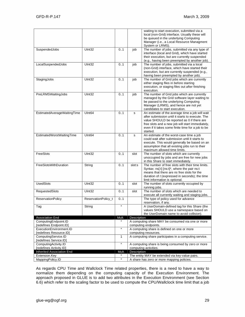
GFD-R-P.147 March 3, 2009
waiting to start execution, submitted via a local (non-Grid) interface. Usually these will
be queued in the underlying Computing Manager (i.e., a Local Resource Managment System or LRMS).
SuspendedJobs UInt32 0..1 job The number of jobs, submitted via any type of interface (local and Grid), which have started their execution, but are currently suspended
(e.g., having been preempted by another job).
LocalSuspendedJobs UInt32 0..1 job The number of jobs, submitted via a local (non-Grid) interface, which have started their
execution, but are currently suspended (e.g., having been preempted by another job).
StagingJobs UInt32 0..1 job The number of Grid jobs which are currently either staging files in before starting execution, or staging files out after finishing
execution.
PreLRMSWaitingJobs UInt32 0..1 job The number of Grid jobs which are currently managed by the Grid software layer waiting to
be passed to the underlying Computing Manager (LRMS), and hence are not yet candidates to start execution.
EstimatedAverageWaitingTime UInt64 0..1 s An estimate of the average time a job will wait after submission until it starts to execute. The value SHOULD be reported as 0 if there are
free slots and a new job will start immediately, even if it takes some finite time for a job to be started.
EstimatedWorstWaitingTime UInt64 0..1 s An estimate of the worst-case time a job could wait after submission until it starts to execute. This would generally be based on an
assumption that all existing jobs run to their maximum allowed time limits.
FreeSlots UInt32 0..1 slot The number of slots which are currently
unoccupied by jobs and are free for new jobs in this Share to start immediately.
FreeSlotsWithDuration String 0..1 slot:s The number of free slots with their time limits. Syntax: ns[:t] [ns:t]*, where the pair ns:t means that there are ns free slots for the
duration of t (expressed in seconds); the time limit information is optional.
UsedSlots UInt32 0..1 slot The number of slots currently occupied by
running jobs.
RequestedSlots UInt32 0..1 slot The number of slots which are needed to execute all currently waiting and staging jobs.
ReservationPolicy ReservationPolicy_t 0..1 The type of policy used for advance reservation, if any.
Tag String * A UserDomain-defined tag for this Share (the values SHOULD use a namespace based on the UserDomain name to avoid collision).
Association End Mult. Description
ComputingEndpoint.ID [redefines Endpoint.ID]
* A computing share MAY be consumed via one or more computing endpoints.
ExecutionEnvironment.ID [redefines Resource.ID]
* A computing share is defined on one or more computing resources.
ComputingService.ID
[redefines Service.ID]
1 A computing share participates in a computing service.
ComputingActivity.ID
[redefines Activity.ID]
* A computing share is being consumed by zero or more
computing activities.
Inherited Association End Mult. Description
Extension.Key * The entity MAY be extended via key-value pairs.
MappingPolicy.ID * A share has zero or more mapping policies.
As regards CPU Time and Wallclock Time related properties, there is a need to have a way to normalize them depending on the computing capacity of the Execution Environment. The approach proposed in GLUE is to add two attributes in the Execution Environment (see Section 6.6) which refer to the scaling factor to be used to compute the CPU/Wallclock time limit that a job

GFD-R-P.147 March 3, 2009
will get if it will be assigned to such an Execution Environment via a certain Share. It is important that a job SHOULD always get at least the advertised CPU/Wallclock time. This means that the reference Execution Environment for the normalization should be always the fastest (most powerful) among those available in the entire Computing Service. For this Execution Environment, the scaling factor MUST be equal to 1. The CPU/Wallclock time values published by a Share therefore refer to the time limit that the job will get when mapped to this Execution Environment. For the other Execution Environments, the time should be adjusted according to the published scaling factors. 6.4 ComputingManager
The ComputingManager class is a specialization of the Manager class for the computational
capability. The ComputingManager is responsible for the local control of resources, and this
layer is not exposed directly to external clients. The operating system might be the simplest case
of a Computing Manager, but the ComputingManager is often realized by means of a Local
Resource Management (LRMS) "batch" system. A Computing Service will usually only have one Computing Manager, but MAY have more. The class provides aggregated information on controlled resources, and also describes local storage extents accessible to jobs. Entity Inherits from Description
ComputingManager Manager A software component locally managing one or more Execution Environments. It MAY also
describe aggregated information about the managed resources. The computing manager is also known
as a Local Resource Management System (LRMS).
Inherited Attribute Type Mult Unit Description
CreationTime DateTime_t 0..1 Timestamp describing when the entity instance was generated
Validity UInt64 0..1 s The duration after CreationTime that the information presented in the Entity SHOULD be considered
relevant. After that period has elapsed, the information SHOULD NOT be
considered relevant
ID [key] URI 1 A global unique ID
Name String 0..1 Human-readable name
OtherInfo
String * Placeholder to publish info that does not fit in any other attribute.
Free-form string, comma-separated tags, (name, value ) pair are all examples of valid syntax
ProductName String 1 Name of the software product adopted as manager
ProductVersion String 0..1 Version of the software product
adopted as manager
Attribute Type Mult. Unit Description
Reservation ExtendedBoolean_t 0..1 True if the Computing Manager (i.e, LRMS) supports advance reservation of resources.
BulkSubmission ExtendedBoolean_t
0..1 True if the computing manager (i.e, LRMS) supports bulk submission of multiple jobs.
TotalPhysicalCPUs UInt32 0..1 Ph.CPU The total number of physical CPUs accessible via any of the available Endpoints and managed by this
Computing Manager (there is one physical CPU per socket). This value SHOULD represent the total
installed capacity, i.e. including resources which are temporarily
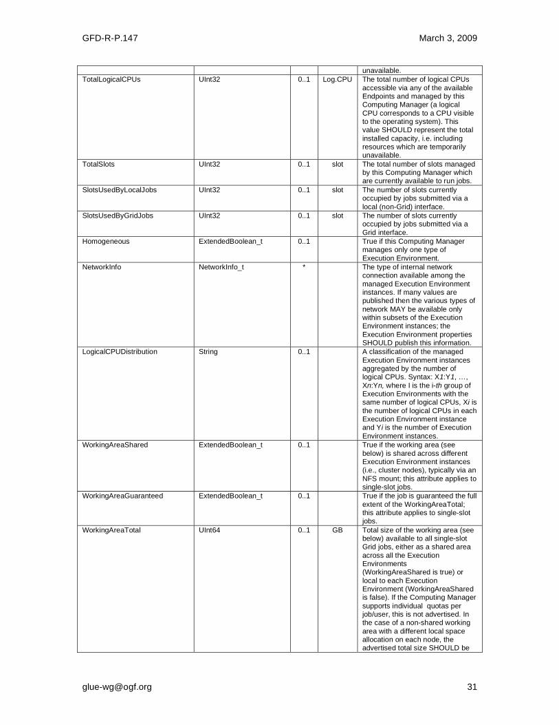
GFD-R-P.147 March 3, 2009
unavailable.
TotalLogicalCPUs UInt32 0..1 Log.CPU The total number of logical CPUs
accessible via any of the available Endpoints and managed by this Computing Manager (a logical
CPU corresponds to a CPU visible to the operating system). This value SHOULD represent the total
installed capacity, i.e. including resources which are temporarily unavailable.
TotalSlots UInt32 0..1 slot The total number of slots managed by this Computing Manager which are currently available to run jobs.
SlotsUsedByLocalJobs UInt32 0..1 slot The number of slots currently occupied by jobs submitted via a
local (non-Grid) interface.
SlotsUsedByGridJobs UInt32 0..1 slot The number of slots currently occupied by jobs submitted via a
Grid interface.
Homogeneous ExtendedBoolean_t 0..1 True if this Computing Manager manages only one type of
Execution Environment.
NetworkInfo NetworkInfo_t * The type of internal network connection available among the
managed Execution Environment instances. If many values are published then the various types of
network MAY be available only within subsets of the Execution Environment instances; the
Execution Environment properties SHOULD publish this information.
LogicalCPUDistribution String 0..1 A classification of the managed
Execution Environment instances aggregated by the number of logical CPUs. Syntax: X1:Y1, …,
Xn:Yn, where I is the i-th group of Execution Environments with the same number of logical CPUs, Xi is
the number of logical CPUs in each Execution Environment instance and Yi is the number of Execution
Environment instances.
WorkingAreaShared ExtendedBoolean_t 0..1 True if the working area (see
below) is shared across different Execution Environment instances (i.e., cluster nodes), typically via an
NFS mount; this attribute applies to single-slot jobs.
WorkingAreaGuaranteed ExtendedBoolean_t 0..1 True if the job is guaranteed the full
extent of the WorkingAreaTotal; this attribute applies to single-slot jobs.
WorkingAreaTotal UInt64 0..1 GB Total size of the working area (see below) available to all single-slot Grid jobs, either as a shared area
across all the Execution Environments (WorkingAreaShared is true) or
local to each Execution Environment (WorkingAreaShared is false). If the Computing Manager
supports individual quotas per job/user, this is not advertised. In the case of a non-shared working
area with a different local space allocation on each node, the advertised total size SHOULD be
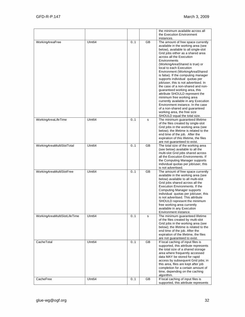
GFD-R-P.147 March 3, 2009
the minimum available across all the Execution Environment
instances.
WorkingAreaFree UInt64 0..1 GB The amount of free space currently available in the working area (see
below), available to all single-slot Grid jobs either as a shared area across all the Execution
Environments (WorkingAreaShared is true) or local to each Execution
Environment (WorkingAreaShared is false). If the computing manager supports individual quotas per
job/user, this is not advertised. In the case of a non-shared and non-guaranteed working area, this
attribute SHOULD represent the minimum free working area currently available in any Execution
Environment instance. In the case of a non-shared and guaranteed working area, the free size
SHOULD equal the total size.
WorkingAreaLifeTime UInt64 0..1 s The minimum guaranteed lifetime of the files created by single-slot
Grid jobs in the working area (see below); the lifetime is related to the end time of the job. After the
expiration of this lifetime, the files are not guaranteed to exist.
WorkingAreaMultiSlotTotal UInt64 0..1 GB The total size of the working area
(see below) available to all the multi-slot Grid jobs shared across all the Execution Environments. If
the Computing Manager supports individual quotas per job/user, this is not advertised.
WorkingAreaMultiSlotFree UInt64 0..1 GB The amount of free space currently available in the working area (see
below) available to all multi-slot Grid jobs shared across all the Execution Environments. If the
Computing Manager supports individual quotas per job/user, this is not advertised. This attribute SHOULD represent the minimum
free working area currently available in any Execution Environment instance.
WorkingAreaMultiSlotLifeTime UInt64 0..1 s The minimum guaranteed lifetime of the files created by multi-slot
Grid jobs in the working area (see below); the lifetime is related to the end time of the job. After the
expiration of the lifetime, the files are not guaranteed to exist.
CacheTotal UInt64 0..1 GB If local caching of input files is
supported, this attribute represents the total size of a shared storage area where frequently accessed
data MAY be stored for rapid access by subsequent Grid jobs; in this area, files are kept after job
completion for a certain amount of time, depending on the caching algorithm.
CacheFree UInt64 0..1 GB If local caching of input files is supported, this attribute represents

GFD-R-P.147 March 3, 2009
the free space in a shared storage area where frequently accessed
data MAY be stored for rapid access by subsequent Grid jobs. In the computation of the free size,
files which are not claimed by any job MAY be considered as deleted.
TmpDir String 0..1 The absolute path of a temporary
directory local to an Execution Environment instance (i.e., a worker node). This directory MUST
be available to programs using the normal file access primitives (open/read/write/close). Any files in
the directory MAY be deleted as soon as the job which created them finishes.
ScratchDir String 0..1 The absolute path of a shared directory available for application data. Typically this is a POSIX
accessible transient disk space shared between the Execution Environment instances, e.g. via an
NFS mount. It MAY be used by MPI applications or to store intermediate files that need further
processing by local jobs or as a staging area, especially if the Execution Environment instances
have no internet connectivity. Any files in the directory MAY be deleted as soon as the job which
created them finishes.
ApplicationDir String 0..1 The path of a directory available for installation of persistent application
software and data. Typically this will be a POSIX accessible disk space, e.g. an NFS mount, with a
long-term allocation of space to supported User Domains. The detailed usage of such a space
SHOULD be described in a profile document for a specific Grid infrastructure.
Association End Mult. Description
ComputingService.ID
[redefines Service.ID]
1 A computing manager participates in a
computing service.
ExecutionEnvironment.ID [redefines Resource.ID]
* A computing manager manages one or more execution environments.
ApplicationEnvironment.ID * A computing manager MAY use zero or more application environments.
Benchmark.ID * A computing manager has zero or more
associated benchmarks.
Inherited Association End Mult. Description
Extension.Key * The entity MAY be extended via key-value pairs.
As regards the WorkingArea-related attributes and single-slot jobs, four scenarios should be considered. Both scenarios and the related attribute values are presented in Table 1.
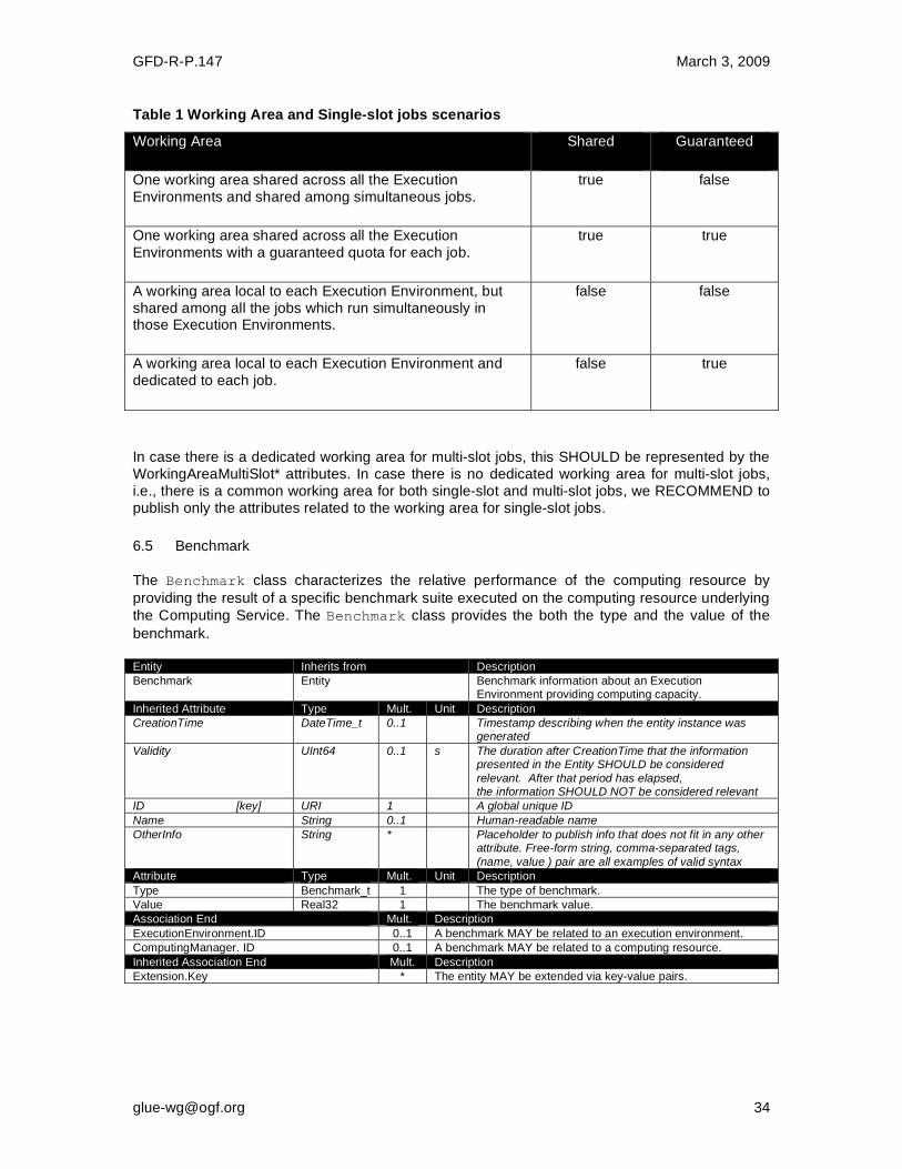
GFD-R-P.147 March 3, 2009
Table 1 Working Area and Single-slot jobs scenarios
Working Area Shared Guaranteed
One working area shared across all the Execution Environments and shared among simultaneous jobs.
true false
One working area shared across all the Execution Environments with a guaranteed quota for each job.
true true
A working area local to each Execution Environment, but shared among all the jobs which run simultaneously in those Execution Environments.
false false
A working area local to each Execution Environment and dedicated to each job.
false true
In case there is a dedicated working area for multi-slot jobs, this SHOULD be represented by the WorkingAreaMultiSlot* attributes. In case there is no dedicated working area for multi-slot jobs, i.e., there is a common working area for both single-slot and multi-slot jobs, we RECOMMEND to publish only the attributes related to the working area for single-slot jobs.
6.5 Benchmark
The Benchmark class characterizes the relative performance of the computing resource by
providing the result of a specific benchmark suite executed on the computing resource underlying
the Computing Service. The Benchmark class provides the both the type and the value of the
benchmark. Entity Inherits from Description
Benchmark Entity Benchmark information about an Execution Environment providing computing capacity.
Inherited Attribute Type Mult. Unit Description
CreationTime DateTime_t 0..1 Timestamp describing when the entity instance was generated
Validity UInt64 0..1 s The duration after CreationTime that the information presented in the Entity SHOULD be considered
relevant. After that period has elapsed, the information SHOULD NOT be considered relevant
ID [key] URI 1 A global unique ID
Name String 0..1 Human-readable name
OtherInfo String * Placeholder to publish info that does not fit in any other attribute. Free-form string, comma-separated tags,
(name, value ) pair are all examples of valid syntax
Attribute Type Mult. Unit Description
Type Benchmark_t 1 The type of benchmark.
Value Real32 1 The benchmark value.
Association End Mult. Description
ExecutionEnvironment.ID 0..1 A benchmark MAY be related to an execution environment.
ComputingManager. ID 0..1 A benchmark MAY be related to a computing resource.
Inherited Association End Mult. Description
Extension.Key * The entity MAY be extended via key-value pairs.

GFD-R-P.147 March 3, 2009
6.6 ExecutionEnvironment
The ExecutionEnvironment class describes the hardware and operating system environment
in which a job will run. It represents a set of homogeneous Worker Nodes, so if a computing system contains nodes with significantly different properties there MAY be several
ExecutionEnvironment instances. This implies that it should be possible to request a specific
environment when a job is submitted. The ExecutionEnvironment MAY refer to virtual rather
than physical machines. As well as attributes describing a typical node, the class gives summary information about the size and usage of the set of nodes which posess those properties. However, there is no way to relate these to the information in other entities, e.g. it is not possible to know which jobs in a given
ComputingShare are running on which ExecutionEnvironment.
Entity Inherits from Description
ExecutionEnvironment Resource A type of environment available to and requestable by a Grid job when submitted to a
ComputingService via a Computing Endpoint; the type of environment is described in terms of hardware, operating system and network
characteristics. Information about the total/available/used instances of this type of execution environment are also included.
Inherited Attribute Type Mult. Unit Description
CreationTime DateTime_t 0..1 Timestamp describing when the entity instance was generated
Validity UInt64 0..1 s The duration after CreationTime that the information presented in the Entity SHOULD be considered relevant. After that period has
elapsed, the information SHOULD NOT be considered relevant
ID [key] URI 1 A global unique ID
Name String 0..1 Human-readable name
OtherInfo String * Placeholder to publish info that does not fit in any other attribute. Free-form string, comma-separated tags, (name, value ) pair are all examples of valid
syntax
Attribute Type Mult. Unit Description
Platform Platform_t 1 The platform architecture of this Execution Environment.
VirtualMachine ExtendedBoolean_t 0..1 True if the Execution Environment is hosted within
a virtual machine; in this case, the values of the other attributes are related to the virtualized environment and not to the hosting environment.
TotalInstances UInt32 0..1 The total number of Execution Environment instances. This SHOULD reflect the total installed capacity, i.e. including resources which are
temporarily unavailable.
UsedInstances UInt32 0..1 The number of Execution Environment instances which are considered to be fully used; an instance
is used when, according to the policies of the Computing Manager (i.e., LRMS), it cannot accept new jobs because it already runs the maximum
number of allowed jobs.
UnavailableInstances UInt32 0..1 The number of Execution Environment instances which are currently unavailable, e.g. because of
failures or maintenance.
PhysicalCPUs UInt32 0..1 The number of physical CPUs in one
ExecutionEnvironment instance, i.e. the number of sockets per Worker Node.
LogicalCPUs UInt32 0..1 The number of logical CPUs in one Execution
Environment instance, i.e. typically the number of cores per Worker Node.
CPUMultiplicity CPUMultiplicity_t 0..1 Condensed information about the multiplicity of
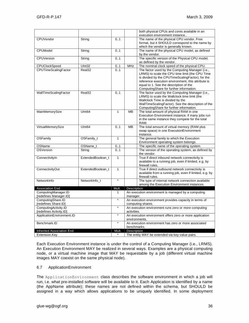
GFD-R-P.147 March 3, 2009
both physical CPUs and cores available in an execution environment instance..
CPUVendor String 0..1 The name of the physical CPU vendor. Free format, but it SHOULD correspond to the name by which the vendor is generally known.
CPUModel String 0..1 The name of the physical CPU model, as defined by the vendor.
CPUVersion String 0..1 The specific version of the Physical CPU model, as defined by the vendor.
CPUClockSpeed UInt32 0..1 MHz The nominal clock speed of the physical CPU.
CPUTimeScalingFactor Real32 0..1 The factor used by the Computing Manager (i.e., LRMS) to scale the CPU time limit (the CPU Time is divided by the CPUTimeScalingFactor); for the
reference execution environment, this attribute is equal to 1. See the description of the ComputingShare for further information.
WallTimeScalingFactor Real32 0..1 The factor used by the Computing Manager (i.e., LRMS) to scale the Wallclock time limit (the Wallclock Time is divided by the
WallTimeScalingFactor). See the description of the ComputingShare for further information.
MainMemorySize UInt64 1 MB The total amount of physical RAM in one Execution Environment instance; if many jobs run in the same instance they compete for the total
RAM.
VirtualMemorySize UInt64 0..1 MB The total amount of virtual memory (RAM plus swap space) in one ExecutionEnvironment
instance.
OSFamily OSFamily_t 1 The general family to which the Execution Environment operating system belongs.
OSName OSName_t 0..1 The specific name of the operating system.
OSVersion String 0..1 The version of the operating system, as defined by the vendor.
ConnectivityIn ExtendedBoolean_t 1 True if direct inbound network connectivity is available to a running job, even if limited, e.g. by
firewall rules.
ConnectivityOut ExtendedBoolean_t 1 True if direct outbound network connectivity is available from a running job, even if limited, e.g. by
firewall rules.
NetworkInfo NetworkInfo_t * The type of internal network connection available among the Execution Environment instances.
Association End Mult. Description
ComputingManager.ID
[redefines Manager.ID]
1 An execution environment is managed by a computing
manager.
ComputingShare.ID [redefines Share.ID]
* An execution environment provides capacity in terms of computing shares.
ComputingActivity.ID [redefines Activity.ID]
* An execution environment runs zero or more computing activities.
ApplicationEnvironment.ID * An execution environment offers zero or more application
environments.
Benchmark.ID * An execution environment has zero or more associated benchmarks.
Inherited Association End Mult. Description
Extension.Key * The entity MAY be extended via key-value pairs.
Each Execution Environment instance is under the control of a Computing Manager (i.e., LRMS). An Execution Environment MAY be realized in several ways. Examples are a physical computing node, or a virtual machine image that MAY be requestable by a job (different virtual machine images MAY coexist on the same physical node). 6.7 ApplicationEnvironment
The ApplicationEnvironment class describes the software environment in which a job will
run, i.e. what pre-installed software will be available to it. Each Application is identified by a name (the AppName attribute); these names are not defined within the schema, but SHOULD be assigned in a way which allows applications to be uniquely identified. In some deployment
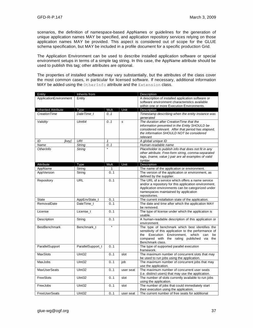
GFD-R-P.147 March 3, 2009
scenarios, the definition of namespace-based AppNames or guidelines for the generation of unique application names MAY be specified, and application repository services relying on those application names MAY be provided. This aspect is considered out of scope for the GLUE schema specification, but MAY be included in a profile document for a specific production Grid. The Application Environment can be used to describe installed application software or special environment setups in terms of a simple tag string. In this case, the AppName attribute should be used to publish this tag; other attributes are optional. The properties of installed software may vary substantially, but the attributes of the class cover the most common cases, in particular for licensed software. If necessary, additional information
MAY be added using the OtherInfo attribute and the Extension class.
Entity Inherits from Description
ApplicationEnvironment Entity A description of installed application software or software environment characteristics available
within one or more Execution Environments.
Inherited Attribute Type Mult. Unit Description
CreationTime DateTime_t 0..1 Timestamp describing when the entity instance was
generated
Validity UInt64 0..1 s The duration after CreationTime that the
information presented in the Entity SHOULD be considered relevant. After that period has elapsed, the information SHOULD NOT be considered
relevant
ID [key] URI 1 A global unique ID
Name String 0..1 Human-readable name
OtherInfo String * Placeholder to publish info that does not fit in any other attribute. Free-form string, comma-separated tags, (name, value ) pair are all examples of valid
syntax
Attribute Type Mult. Unit Description
AppName String 1 The name of the application or environment.
AppVersion String 0..1 The version of the application or environment, as defined by the supplier.
Repository URL 0..1 The URL of a service which offers a name service and/or a repository for this application environment. Application environments can be categorized under
namespaces maintained by application repositories.
State AppEnvState_t 0..1 The current installation state of the application.
RemovalDate DateTime_t 0..1 The date and time after which the application MAY be removed.
License License_t 0..1 The type of license under which the application is usable.
Description String 0..1 A human-readable description of this application or
environment.
BestBenchmark Benchmark_t * The type of benchmark which best identifies the sensitivity of this application to the performance of
the Execution Environment, which can be compared with the rating published via the Benchmark class.
ParallelSupport ParallelSupport_t 0..1 The type of supported parallel execution framework.
MaxSlots UInt32 0..1 slot The maximum number of concurrent slots that may be used to run jobs using the application.
MaxJobs UInt32 0..1 job The maximum number of concurrent jobs that may
use the application.
MaxUserSeats UInt32 0..1 user seat The maximum number of concurrent user seats (i.e. distinct users) that may use the application.
FreeSlots UInt32 0..1 slot The number of slots currently available to run jobs using the application.
FreeJobs UInt32 0..1 slot The number of jobs that could immediately start their execution using the application.
FreeUserSeats UInt32 0..1 user seat The current number of free seats for additional

GFD-R-P.147 March 3, 2009
users to use the application.
Association End Mult. Description
ExecutionEnvironment.ID * An application environment MAY be used in zero or more execution environments.
ComputingManager.ID 1 An application environment is part of a computing manager.
ApplicationHandle.ID * An application environment MAY be handled via zero or more application handles.
Inherited Association End Mult. Description
Extension.Key * The entity MAY be extended via key-value pairs.
6.8 ApplicationHandle
The ApplicationHandle class is an extension to ApplicationEnvironment for
applications which need to be set up in some way before they can be used. For each supported setup method a string MAY be specified, the interpretation of which is specific to the method - in the simplest case this could just be a setup script to execute. A single Application MAY support multiple setup methods. Entity Inherits from Description
ApplicationHandle Entity The description of a technique for bootstrapping and/or accessing an application environment.
Inherited Attribute Type Mult. Unit Description
CreationTime DateTime_t 0..1 Timestamp describing when the entity instance was generated
Validity UInt64 0..1 s The duration after CreationTime that the information presented in the Entity SHOULD be considered relevant. After that period has elapsed,
the information SHOULD NOT be considered relevant
ID [key] URI 1 A global unique ID
Name String 0..1 Human-readable name
OtherInfo String * Placeholder to publish info that does not fit in any other attribute. Free-form string, comma-separated
tags, (name, value ) pair are all examples of valid syntax
Attribute Type Mult. Unit Description
Type ApplicationHandle_t 1 The type of method used to set up this application environment.
Value String 1 A string which defines how to set up this application in the context of the setup method specified by the Type.
Association End Mult. Description
ApplicationEnvironment.ID 1 An application handle MAY be used for one application environment.
Inherited Association End Mult. Description
Extension.Key * The entity MAY be extended via key-value pairs.
6.9 ComputingActivity
The ComputingActivity class represents a single (but possibly multi-processor) job. The
attributes give the job properties and state as seen by the local batch system, together with some Grid-level information. Entity Inherits from Description
ComputingActivity
Activity An Activity managed by an OGSA execution capability service (the Computing Activity is traditionally
called a job).
Inherited Attribute Type Mult Unit Description
CreationTime DateTime_t 0..1 Timestamp describing when the entity instance was generated
Validity UInt64 0..1 s The duration after CreationTime
that the information presented in the Entity SHOULD be considered
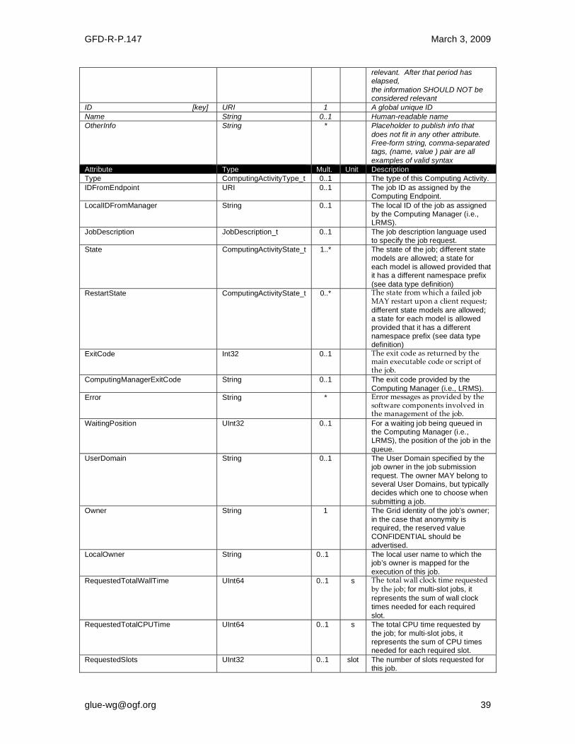
GFD-R-P.147 March 3, 2009
relevant. After that period has elapsed,
the information SHOULD NOT be considered relevant
ID [key] URI 1 A global unique ID
Name String 0..1 Human-readable name
OtherInfo String * Placeholder to publish info that
does not fit in any other attribute. Free-form string, comma-separated tags, (name, value ) pair are all
examples of valid syntax
Attribute Type Mult. Unit Description
Type ComputingActivityType_t 0..1 The type of this Computing Activity.
IDFromEndpoint URI 0..1 The job ID as assigned by the Computing Endpoint.
LocalIDFromManager String 0..1 The local ID of the job as assigned by the Computing Manager (i.e., LRMS).
JobDescription JobDescription_t 0..1 The job description language used to specify the job request.
State ComputingActivityState_t 1..* The state of the job; different state
models are allowed; a state for each model is allowed provided that it has a different namespace prefix
(see data type definition)
RestartState ComputingActivityState_t 0..* The state from which a failed job MAY restart upon a client request; different state models are allowed; a state for each model is allowed
provided that it has a different namespace prefix (see data type definition)
ExitCode Int32 0..1 The exit code as returned by the main executable code or script of the job.
ComputingManagerExitCode String 0..1 The exit code provided by the
Computing Manager (i.e., LRMS).
Error String * Error messages as provided by the software components involved in the management of the job.
WaitingPosition UInt32 0..1 For a waiting job being queued in the Computing Manager (i.e., LRMS), the position of the job in the
queue.
UserDomain String 0..1 The User Domain specified by the job owner in the job submission
request. The owner MAY belong to several User Domains, but typically decides which one to choose when
submitting a job.
Owner String 1 The Grid identity of the job’s owner;
in the case that anonymity is required, the reserved value CONFIDENTIAL should be
advertised.
LocalOwner String 0..1 The local user name to which the job’s owner is mapped for the
execution of this job.
RequestedTotalWallTime UInt64 0..1 s The total wall clock time requested by the job; for multi-slot jobs, it
represents the sum of wall clock times needed for each required
slot. RequestedTotalCPUTime UInt64 0..1 s The total CPU time requested by
the job; for multi-slot jobs, it represents the sum of CPU times needed for each required slot.
RequestedSlots UInt32 0..1 slot The number of slots requested for this job.

GFD-R-P.147 March 3, 2009
RequestedApplicationEnvironment String * A serialization of the AppName and Version of the requested
Application Environments (the serialization syntax is delegated to the implementation).
StdIn String 0..1 The name of the file which is used as the standard input of the job.
StdOut String 0..1 The name of the file which contains the standard output of the job.
StdErr String 0..1 The name of the file which contains the standard error of the job.
LogDir String 0..1 The name of the directory which contains the logs related to the job and generated by the Grid layer (usually the directory is private to the job).
ExecutionNode String * A hostname associated to the Execution Environment instance (i.e., worker node) running the job; multi-node jobs are described by several instances of this attribute.
Queue String 0..1 The name of the Computing Manager (i.e, LRMS) queue in
which this job was queued before execution.
UsedTotalWallTime UInt64 0..1 s The total wall clock time consumed so far by the job. In case of multi-
slot jobs, this value refers to the sum of the wall clock time consumed in each slot.
UsedTotalCPUTime UInt64 0..1 s The total CPU time consumed so far by the job. In case of multi-slot jobs, this value refers to the sum of
the CPU time consumed in each slot.
UsedMainMemory UInt64 0..1 MB The physical RAM currently used by the job.
SubmissionTime DateTime_t 0..1 The time when the job was submitted to the Computing Endpoint.
ComputingManagerSubmissionTime DateTime_t 0..1 The time when the job was submitted to the Computing Manager (i.e., LRMS) by the Grid layer.
StartTime DateTime_t 0..1 The time when the job entered the Computing Manager (i.e., LRMS) running state.
ComputingManagerEndTime DateTime_t 0..1 The time when the job entered its final Computing Manager (i.e., LRMS) state.
EndTime DateTime_t 0..1 The time when the job entered its final state as recorded by the Grid layer.
WorkingAreaEraseTime DateTime_t 0..1 A working area is an allocated storage extent that holds the home
directories of the Grid jobs; this attribute specifies the time when the dedicated working area of this
job will be removed.
ProxyExpirationTime DateTime_t 0..1 The expiration time of the Grid proxy currently associated with the job; in case of a proxy with attribute certificates having different expiration times, then this value represent the minimum expiration time among all the values.
SubmissionHost
String 0..1 The name of the host from which the job was submitted.

GFD-R-P.147 March 3, 2009
SubmissionClientName String 0..1 The name of the software client which was used to submit the job.
OtherMessages String * Optional job messages provided by either the Grid Layer or the Computing Manager (i.e., LRMS).
Association End Mult. Description
ComputingEndpoint.ID [redefines Endpoint.ID]
0..1 A computing activity is submitted to a computing endpoint.
ComputingShare.ID
[redefines Share.ID]
0..1 A computing activity is mapped into a
computing share.
ExecutionEnvironment.ID
[redefines Resource.ID]
0..1 A computing activity is executed in an
execution environment.
Inherited Association End Mult. Description
Extension.Key * The entity MAY be extended via key-value
pairs.
UserDomain.ID 0..1 An activity is managed by a user domain.
Activity.ID * An activity is related to zero or more activities.
Activity.ID * An activity is related to zero or more
activities.
In this specification, the Computing Activity may refer to simple jobs, or to elements of collections or workflows. The description of the relationships between jobs which are part of a collection or workflow may be considered in future revisions of the specification. As regards the State attribute and the related ComputingActivityState_t type, we note that currently there is no commonly accepted state model for Grid jobs. Each production Grid middleware defines and is using its own state model. As regards the standardization process, the OGSA-BES specification defines a simple state model. The middleware providers have started to define their own extensions to the BES state model, but they differ and do not enable interoperability. Given the current scenario, we RECOMMEND to use namespaces in state model values, so that every middleware provider MAY publish the Computing Activity State according to its definition. We expect that an extension to the core BES state model common to all the middleware providers and suitable for production scenarios may be defined by a profiling activity of the BES/ JSDL/GLUE specifications. 6.10 ToStorageService
The ToStorageService class represents the case where a filesystem from a Storage Service
is available to jobs running on a Computing Service via POSIX access, e.g. as an NFS mount.
Each ToStorageService instance represents a single mount point. It is assumed that such
mounts are available on all nodes (i.e. all Execution Environments) in the Computing Service. Entity Inherits from Description
ToStorageService Entity The description of POSIX access via a file system technology enabling jobs running in the Computing Service to access an associated
Storage Service.
Inherited Attribute Type Mult Unit Description
CreationTime DateTime_t 0..1 Timestamp describing when the entity instance
was generated
Validity UInt64 0..1 s The duration after CreationTime that the
information presented in the Entity SHOULD be considered relevant. After that period has elapsed, the information SHOULD NOT be considered
relevant
ID [key] URI 1 A global unique ID
Name String 0..1 Human-readable name

GFD-R-P.147 March 3, 2009
OtherInfo String * Placeholder to publish info that does not fit in any other attribute. Free-form string, comma-
separated tags, (name, value ) pair are all examples of valid syntax
Attribute Type Mult. Unit Description
LocalPath String 1 The local path within the Computing Service which makes it possible to access files in the associated Storage Service (this is typically an
NFS mount point).
RemotePath String 1 The remote path in the Storage Service which is
associated to the local path in the Computing Service (this is typically an NFS exported directory).
Association End Mult. Description
ComputingService.ID 1 Is associated to a computing service.
StorageService.ID 1 Is associated to a storage service.
Inherited Association End Mult. Description
Extension.Key * The entity MAY be extended via key-value pairs.

GFD-R-P.147 March 3, 2009
7 Conceptual Model of the Storage Service
The conceptual model of the Storage Service is based on the main entities and uses
specializations of the Service, Endpoint, Share, Manager, Resource, and Activity
entities. Further storage-related concepts such as Storage Service Capacity, Storage
Share Capacity and Storage Access Protocol are also introduced.
Figure 3 Entities and relationships for the Storage Service conceptual model
As explained in Section 6, we use the concept of storage extent to mean the capabilities and management of the various media that exist to store data and allow data retrieval.

GFD-R-P.147 March 3, 2009
7.1 StorageService
A StorageService represents a Grid-enabled storage system, most often hosted by a single
site, but possibly distributed over multiple sites. A StorageService makes StorageShares of
given properties available to selected UserDomains, typically (not necessarily) through one or
more explicitly identified StorageEndpoints. Data may be stored in or retrieved from
StorageShares through one or more StorageAccessProtocols. A StorageShare is a
composition of extents from one or more DataStores. StorageShares MAY overlap, i.e. map
to the same underlying extent. A DataStore represents a physical device that holds data (e.g. a
disk farm or a tape robot). Each DataStore is managed by a StorageManager, an instance of
a particular software product identified by the ProductName and ProductVersion. StorageServiceCapacity objects summarize capacity-related information, for which details
may be available associated to StorageShares and DataStores.
Entity Inherits from Description
StorageService Service An abstracted, logical view of software and hardware components that participate in the creation of a storage
capability in a Grid environment. A Storage Service exposes zero or more Endpoints having well-defined interfaces, zero or more Storage Shares and zero or
more Storage Managers and the related Data Stores. The Storage Service also offers zero or more Storage Access Protocols, and provides summary information
about the overall amount of storage by means of the Storage Service Capacity.
The Storage Service is autonomous and denotes a weak aggregation among Storage Endpoints, Storage Shares, Storage Managers, Storage Access Protocols and
Storage Service Capacities. The Storage Service enables the identification of the entire set of entities providing storage functionality with a persistent name.
Inherited Attribute Type Mult Unit Description
CreationTime DateTime_t 0..1 Timestamp describing when the entity instance was generated
Validity UInt64 0..1 s The duration after CreationTime that the information presented in the Entity SHOULD be considered relevant. After that period has elapsed,
the information SHOULD NOT be considered relevant
ID [key] URI 1 A global unique ID
Name String 0..1 Human-readable name
OtherInfo String * Placeholder to publish info that does not fit in any other attribute. Free-form string, comma-separated tags,
(name, value ) pair are all examples of valid syntax
Capability Capability_t * The provided capability according to the Open Grid Service Architecture (OGSA) architecture [OGF-GFD80]
(this is the union of all values assigned to the capability attribute of the endpoints part of this service)
Type ServiceType_t 1 The type of service according to a namespace-based
classification (the namespace MAY be related to a middleware name, an organization or other concepts; org.ogf.glue is reserved for the OGF GLUE Working
Group)
QualityLevel QualityLevel_t 1 Maturity of the service in terms of quality of the software
components
StatusInfo URI * Web page providing additional information like monitoring aspects
Complexity String 0..1 Human-readable summary description of the complexity in terms of the number of endpoint types, shares and resources. The syntax should be: endpointType=X,
share=Y, resource=Z.
Attribute Type Mult Unit Description
No extra properties are defined in the specialized entity.

GFD-R-P.147 March 3, 2009
Association End Mult. Description
StorageEndpoint.ID
[redefines Endpoint.ID]
* A storage service exposes zero or more storage endpoints.
StorageShare.ID [redefines Share.ID]
* A storage service serves zero or more storage shares.
StorageManager.ID [redefines Manager.ID]
* A storage service provides zero or more storage managers.
StorageAccessProtocol.ID * A storage service offers zero or more storage access protocols.
StorageServiceCapacity.ID * A storage service has zero or more storage service
capacities.
Inherited Association End Mult. Description
Extension.Key * The entity MAY be extended via key-value pairs.
Contact.ID * A service has zero or more contacts.
Location.ID 0..1 A service is primary located at a location.
Service.ID * A service is related to zero or more services.
The Storage Service MAY expose Storage Endpoints enabling management of or access to different types of storage extent. The usage of storage is typically constrained by policies, thus implying service differentiation. The Storage Share concept describes a portion of the managed storage extents with a homogeneous set of usage policies. The storage extents used to implement the Shares are locally managed by one or more Storage Managers, and their properties are described by Data Stores. 7.2 StorageServiceCapacity
The StorageServiceCapacity class summarizes capacity-related information for all the
StorageShares and DataStores of a given homogeneous type. The summaries MAY be
compared to the sums of the relevant StorageShareCapacity attributes for the
StorageShares of the given type. Capacities of overlapping StorageShares MUST only be
counted once. An inconsistency between a summary value and the corresponding sum of relevant attributes MAY occur if part of the capacity is not explicitly published, or if the attributes concerned could not all be exactly determined or recorded at the same time. The summaries
MAY also be compared to the sums of the relevant attributes of the DataStores of the given
type, where inconsistencies MAY arise due to similar causes. Entity Inherits from Description
StorageServiceCapacity Entity Description of the size and usage of a
homogenous storage extent; the storage extent is aggregated at the storage service level by type.
Inherited Attribute Type Mult Unit Description
CreationTime DateTime_t 0..1 Timestamp describing when the entity instance
was generated
Validity UInt64 0..1 s The duration after CreationTime that the information presented in the Entity SHOULD be
considered relevant. After that period has elapsed, the information SHOULD NOT be considered
relevant
ID [key] URI 1 A global unique ID
Name String 0..1 Human-readable name
OtherInfo String * Placeholder to publish info that does not fit in any other attribute. Free-form string, comma-separated tags, (name, value ) pair are all
examples of valid syntax
Attribute Type Mult. Unit Description
Type StorageCapacity_t 1 The type of storage capacity.
TotalSize UInt64 0..1 GB The total amount of storage of this Type (the sum of free, used and reserved).
FreeSize UInt64 0..1 GB The amount of storage which is free for new data to be stored. This SHOULD include space occupied by cached copies of files which can be

GFD-R-P.147 March 3, 2009
deleted automatically to make room for new files.
UsedSize UInt64 0..1 GB The amount of storage which is occupied by stored data. This SHOULD exclude space occupied by cached copies of files which can be
deleted automatically to make room for new files.
ReservedSize UInt64 0..1 GB The amount of storage which is not occupied by
stored data, but has been reserved for use by a specific user or group, and hence is not free for the storage of new data except in the context of
that reservation.
Association End Mult. Description
StorageService.ID 1 A storage service capacity is related to one storage service.
Inherited Association End Mult. Description
Extension.Key * The entity MAY be extended via key-value pairs.
7.3 StorageAccessProtocol
A StorageAccessProtocol describes a protocol that can be used to store data in or retrieve
data from StorageShares. The "file" protocol indicates that for ComputingServices given by
ToComputingService objects the StorageShares are available through POSIX I/O. The
mount point details are given by corresponding ToStorageService objects published by those
ComputingServices. Most protocols require a negotiation between the client and a
StorageEndpoint. For example, a StorageEndpoint implementing a version of the SRM
protocol may be asked for a data transfer URL corresponding to a desired access protocol. An access protocol that does not require prior negotiation MAY be published as one or more
StorageEndpoints with an InterfaceName corresponding to that protocol.
Entity Inherits from Description
StorageAccessProtocol Entity A type of protocol available to access the
underlying storage extents.
Inherited Attribute Type Mult Unit Description
CreationTime DateTime_t 0..1 Timestamp describing when the entity
instance was generated
Validity UInt64 0..1 s The duration after CreationTime that the
information presented in the Entity SHOULD be considered relevant. After that period has elapsed,
the information SHOULD NOT be considered relevant
ID [key] URI 1 A global unique ID
Name String 0..1 Human-readable name
OtherInfo String * Placeholder to publish info that does not fit in any other attribute. Free-form string,
comma-separated tags, (name, value ) pair are all examples of valid syntax
Attribute Type Mult. Unit Description
Type StorageAccessProtocol_t 1 An identifier for the protocol.
Version String 1 The version of the protocol supported by the
interface, as defined by the protocol specification.
MaxStreams UInt32 0..1 stream The maximum number of parallel network
streams which can be used for a single data transfer operation using this protocol.
Association End Mult. Description
StorageService.ID 1 A storage access protocol is related to one storage service.
ToComputingService * A storage access protocol MAY be used by zero or more computing services.
Inherited Association End Mult. Description
Extension.Key * The entity MAY be extended via key-value pairs.
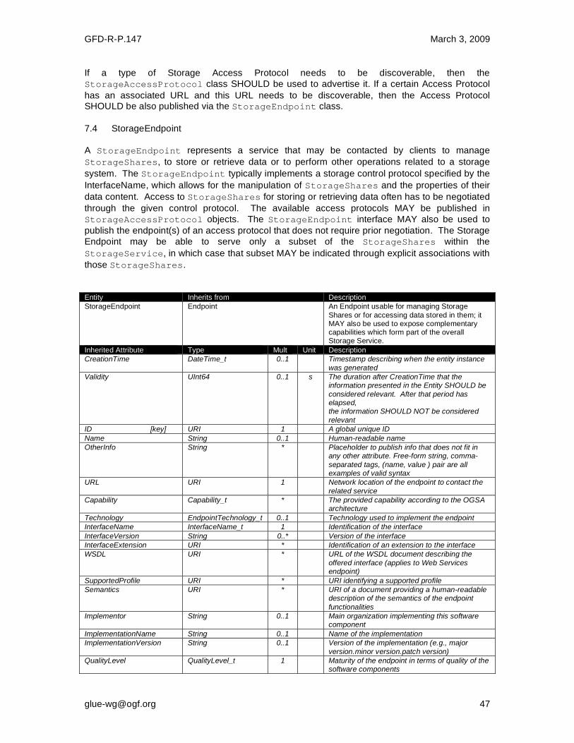
GFD-R-P.147 March 3, 2009
If a type of Storage Access Protocol needs to be discoverable, then the
StorageAccessProtocol class SHOULD be used to advertise it. If a certain Access Protocol
has an associated URL and this URL needs to be discoverable, then the Access Protocol SHOULD be also published via the StorageEndpoint class.
7.4 StorageEndpoint
A StorageEndpoint represents a service that may be contacted by clients to manage
StorageShares, to store or retrieve data or to perform other operations related to a storage
system. The StorageEndpoint typically implements a storage control protocol specified by the
InterfaceName, which allows for the manipulation of StorageShares and the properties of their
data content. Access to StorageShares for storing or retrieving data often has to be negotiated
through the given control protocol. The available access protocols MAY be published in
StorageAccessProtocol objects. The StorageEndpoint interface MAY also be used to
publish the endpoint(s) of an access protocol that does not require prior negotiation. The Storage
Endpoint may be able to serve only a subset of the StorageShares within the
StorageService, in which case that subset MAY be indicated through explicit associations with
those StorageShares.
Entity Inherits from Description
StorageEndpoint Endpoint An Endpoint usable for managing Storage
Shares or for accessing data stored in them; it MAY also be used to expose complementary capabilities which form part of the overall Storage Service.
Inherited Attribute Type Mult Unit Description
CreationTime DateTime_t 0..1 Timestamp describing when the entity instance
was generated
Validity UInt64 0..1 s The duration after CreationTime that the information presented in the Entity SHOULD be
considered relevant. After that period has elapsed, the information SHOULD NOT be considered
relevant
ID [key] URI 1 A global unique ID
Name String 0..1 Human-readable name
OtherInfo String * Placeholder to publish info that does not fit in any other attribute. Free-form string, comma-
separated tags, (name, value ) pair are all examples of valid syntax
URL URI 1 Network location of the endpoint to contact the
related service
Capability Capability_t * The provided capability according to the OGSA architecture
Technology EndpointTechnology_t 0..1 Technology used to implement the endpoint
InterfaceName InterfaceName_t 1 Identification of the interface
InterfaceVersion String 0..* Version of the interface
InterfaceExtension URI * Identification of an extension to the interface
WSDL URI * URL of the WSDL document describing the
offered interface (applies to Web Services endpoint)
SupportedProfile URI * URI identifying a supported profile
Semantics URI * URI of a document providing a human-readable description of the semantics of the endpoint
functionalities
Implementor String 0..1 Main organization implementing this software component
ImplementationName String 0..1 Name of the implementation
ImplementationVersion String 0..1 Version of the implementation (e.g., major
version.minor version.patch version)
QualityLevel QualityLevel_t 1 Maturity of the endpoint in terms of quality of the software components

GFD-R-P.147 March 3, 2009
HealthState EndpointHealthState_t 1 A state representing the health of the endpoint in terms of its capability of properly delivering
the functionalities
HealthStateInfo String 0..1 Textual explanation of the state endpoint
ServingState ServingState_t 1 A state specifying if the endpoint is accepting
new requests and if it is serving the already accepted requests
StartTime DateTime_t 0..1 The timestamp for the start time of the endpoint
IssuerCA DN_t 0..1 Distinguished name of Certification Authority issuing the certificate for the endpoint
TrustedCA DN_t * Distinguished name of the trusted Certification Authority (CA), i.e., certificates issued by the CA are accepted for the authentication process
DowntimeAnnounce DateTime_t 0..1 The timestamp for the announcement of the next scheduled downtime
DowntimeStart DateTime_t 0..1 The starting timestamp of the next scheduled downtime
DowntimeEnd DateTime_t 0..1 The ending timestamp of the next scheduled
downtime
DowntimeInfo String 0..1 Description of the next scheduled downtime
Attribute Type Mult. Unit Description
No extra properties are defined in the specialized entity.
Association End Mult. Description
StorageService.ID [redefines Service.ID]
1 A storage endpoint is part of a storage service.
StorageShare.ID
[redefines Share.ID]
* A storage endpoint MAY pass activities to zero or more
storage shares.
Inherited Association End Mult. Description
Extension.Key * The entity MAY be extended via key-value pairs.
AccessPolicy.ID * An endpoint has assocated zero or more AccessPolicies.
7.5 StorageShare
A StorageShare is a composition of extents from one or more DataStores. StorageShares
that overlap, i.e. share the same underlying extent, have the same SharingID, which in that case
MUST neither be empty nor the reserved string "dedicated". A DataStore represents a physical
device or set of devices that are able to hold data (e.g. a disk farm or a tape robot). A
StorageShare need not be composed of homogeneous devices.
The AccessLatency gives the maximum latency category for a file stored in the StorageShare to
be made available for reading. For example, if the StorageShare comprises both disk and tape
storage, and data may need to be recalled from tape, the published AccessLatency is "nearline", although a given file may in fact be immediately accessible on disk.
The RetentionPolicy indicates at a coarse granularity the probability of the StorageShare losing
data. For example, "custodial" represents a very low probability, while "replica" indicates that the
StorageShare is not suitable for keeping the only copy of precious data, but may be used for
keeping a replica of such data. The ExpirationMode indicates what happens to data whose lifetime has expired, if ever. The
Identifier allows the StorageShare to be given a tag that is meaningful for the UserDomain(s)
served by the StorageShare. For example, for version 2.2 of the SRM control protocol a
StorageShare would represent a Space and the Identifier the corresponding
SpaceTokenUserDescription. Capacity-related information is made available through
StorageShareCapacity objects. A StorageShare may not be available through
StorageEndpoints not explicitly related to the Share.

GFD-R-P.147 March 3, 2009
Entity Inherits from Description
StorageShare
Share A utilization target for a set of extents in Data
Stores, defined by a set of configuration parameters and policies and characterized by status information.
Inherited Attribute Type Mult Unit Description
CreationTime DateTime_t 0..1 Timestamp describing when the entity instance
was generated
Validity UInt64 0..1 s The duration after CreationTime that the information presented in the Entity SHOULD be
considered relevant. After that period has elapsed, the information SHOULD NOT be considered
relevant
ID [key] URI 1 A global unique ID
Name String 0..1 Human-readable name
OtherInfo String * Placeholder to publish info that does not fit in any other attribute. Free-form string, comma-
separated tags, (name, value ) pair are all examples of valid syntax
Description String 0..1 Description of this share
Attribute Type Mult. Unit Description
ServingState ServingState_t 1 A state specifying whether the Share is open to place new requests, and if it is currently offering
any requests already present for execution.
Path String 0..1 A default namespace where files are logically placed when they are stored into this Share. This
will typically be used as a prefix when generating a file name under which the file is stored.
AccessMode AccessMode_t 0..* An identifier for the type of access and usage allowed for this Share.
SharingID LocalID_t 1 A local identifier common to the set of Storage
Shares which use the same underlying extents, i.e. which share the same pool of storage space. (‘dedicated’ is a reserved value which means that
the Storage Share extents are not shared with other Storage Shares.)
AccessLatency AccessLatency_t 1 The maximum latency category under normal
operating conditions for a file stored in this share to be made available for reading.
RetentionPolicy RetentionPolicy_t * The quality of data retention, which indicates the
probability of the storage system losing a file.
ExpirationMode ExpirationMode_t 0..3 An attribute which indicates support for files with
infinite and/or finite lifetimes, and what actions the storage service may take upon the expiration of a file lifetime.
DefaultLifeTime UInt32 0..1 s The default lifetime assigned to a new file if no explicit lifetime is specified.
MaximumLifeTime UInt32 0..1 s The maximum lifetime that may be requested for a
file.
Tag String 0..1 An identifier defined by a User Domain which identifies a Share with a specific set of properties.
Association End Mult. Description
StorageEndpoint.ID
[redefines Endpoint.ID]
* A storage share is consumed via zero or more endpoints.
DataStore.ID [redefines Resource.ID]
* A storage share is defined on zero or more data stores.
StorageService.ID [redefines Service.ID]
1 A storage share participates in a storage service.
StorageShareCapacity.ID * A storage share offers zero or more storage share
capacities.
Inherited Association End Mult. Description
Extension.Key * The entity MAY be extended via key-value pairs.
MappingPolicy.ID * A share has zero or more mapping policies.
A Storage Share represents a utilization target of one or more storage extents with a set of policies which are homogeneous. If many User Domains are mapped to a Storage Share via a

GFD-R-P.147 March 3, 2009
Mapping Policy, then they are assumed to be able to use the Share uniformly. A Storage Share MAY have many types of Storage Capacity. The usage of each type of Storage Capacity is described by the StorageShareCapacity class. 7.6 StorageShareCapacity The StorageShareCapacity class provides a set of attributes related to the size of the data
storage extents associated with a StorageShare. One StorageShare MAY have several
associated StorageShareCapacity objects of different types, which may be related either to
the physical nature of the storage medium or to the intended use, e.g. accounting or resource discovery. It is therefore possible that the same physical storage MAY be reported in more than one object. The size information generally relates to the values as seen by a user of the
Service, which may not correspond directly to the size of the physical storage media which
underly it. For example, disk servers may include parity disks or hot spares which are not directly visible to users.
The semantics of this class are the same as the StorageServiceCapacity class which
represent the size of the entire Storage Service, but the classes are different since the
relations are different. In general it cannot be assumed that the Storage Service Capacity
is the sum of all the corresponding Storage Share Capacities, both because some
information at the Share level MAY not be published, and because multiple StorageShare
objects MAY share the same physical storage. There may also be differences in timing or accuracy in the underlying services which collect the information. Entity Inherits from Description
StorageShareCapacity Entity A description of the size and usage of a
homogenous storage extent available to a Storage Share.
Inherited Attribute Type Mult Unit Description
CreationTime DateTime_t 0..1 Timestamp describing when the entity instance was generated
Validity UInt64 0..1 s The duration after CreationTime that the information presented in the Entity SHOULD be considered relevant. After that period has
elapsed, the information SHOULD NOT be considered relevant
ID [key] URI 1 A global unique ID
Name String 0..1 Human-readable name
OtherInfo String * Placeholder to publish info that does not fit in any other attribute. Free-form string, comma-separated tags, (name, value ) pair are all
examples of valid syntax
Attribute Type Mult. Unit Description
Type StorageCapacity_t 1 The type of storage capacity.
TotalSize UInt64 0..1 GB The total amount of storage of this Type (the sum of free, used and reserved).
FreeSize UInt64 0..1 GB The amount of storage which is free for new data to be stored. This SHOULD include space occupied by cached copies of files which can be
deleted automatically to make room for new files.
UsedSize UInt64 0..1 GB The amount of storage which is occupied by
stored data. This SHOULD exclude space occupied by cached copies of files which can be deleted automatically to make room for new
files.
ReservedSize UInt64 0..1 GB The amount of storage which is not occupied by stored data, but has been reserved for use by a
specific user or group, and hence is not free for the storage of new data except in the context of that reservation.

GFD-R-P.147 March 3, 2009
Association End Mult. Description
StorageShare.ID 1 A storage share capacity is related to one storage share.
Inherited Association End Mult. Description
Extension.Key * The entity MAY be extended via key-value pairs.
The Storage Share Capacity is useful to express the usage information of a homogenous storage extent allocated to a Share. Such usage information refers to use by the User Domains which are related to the Storage Share via Mapping Policies. 7.7 StorageManager
The StorageManager class respresents the software system which manages the data storage
media. If different media, e.g. tape and disk, are managed by different software systems there
MAY be multiple StorageManager instances for a single StorageService. In some systems
there may be a number of layers of software, but this cannot be represented. At present no
attributes are defined beyond those inherited from the Manager entity, i.e. the Name and Version
of the software product. Entity Inherits from Description
StorageManager Manager The primary software component locally managing one or more Data Stores. It MAY also
be used to describe aggregated information about the managed resources.
Inherited Attribute Type Mult Unit Description
CreationTime DateTime_t 0..1 Timestamp describing when the entity instance was generated
Validity UInt64 0..1 s The duration after CreationTime that the information presented in the Entity SHOULD be considered relevant. After that period has
elapsed, the information SHOULD NOT be considered relevant
ID [key] URI 1 A global unique ID
Name String 0..1 Human-readable name
OtherInfo String * Placeholder to publish info that does not fit in
any other attribute. Free-form string, comma-separated tags, (name, value ) pair are all examples of valid syntax
ProductName String 1 Name of the software product adopted as manager
ProductVersion String 0..1 Version of the software product adopted as manager
Attribute Type Mult. Unit Description
No extra properties are defined in the specialized entity.
Association End Mult. Description
StorageService.ID [redefines Service.ID]
1 A storage manager participates in a storage service.
DataStore.ID
[redefines Resource.ID]
* A storage manager manages zero or more data stores.
Inherited Association End Mult. Description
Extension.Key * The entity MAY be extended via key-value pairs.
7.8 DataStore
The DataStore class represents the physical storage systems underlying the Storage
Service. Typically there will be one DataStore instance for each homogeneous type of
storage, e.g. tape and disk. However, multiple objects of the same Type MAY be published if the storage is segmented at a high level, e.g. if there are two separate robotic tape stores. The size information relates to the physical capacity of the storage media, which may differ from the values reported in the Capacity classes.
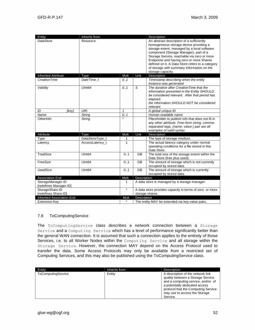
GFD-R-P.147 March 3, 2009
Entity Inherits from Description
DataStore Resource An abstract description of a sufficiently
homogeneous storage device providing a storage extent, managed by a local software component (Storage Manager), part of a
Storage Service, reachable via zero or more Endpoints and having zero or more Shares defined on it. A Data Store refers to a category
of storage with summary information on the storage capacity.
Inherited Attribute Type Mult. Unit Description
CreationTime DateTime_t 0..1 Timestamp describing when the entity instance was generated
Validity UInt64 0..1 S The duration after CreationTime that the information presented in the Entity SHOULD be considered relevant. After that period has
elapsed, the information SHOULD NOT be considered relevant
ID [key] URI 1 A global unique ID
Name String 0..1 Human-readable name
OtherInfo String * Placeholder to publish info that does not fit in
any other attribute. Free-form string, comma-separated tags, (name, value ) pair are all examples of valid syntax
Attribute Type Mult. Unit Description
Type DataStoreType_t 1 The type of storage medium.
Latency AccessLatency_t 1 The actual latency category under normal operating conditions for a file stored in this Data Store.
TotalSize UInt64 0..1 GB The total size of the storage extent within the Data Store (free plus used).
FreeSize UInt64 0..1 GB The amount of storage which is not currently
occupied by stored data.
UsedSize UInt64 0..1 GB The amount of storage which is currently
occupied by stored data.
Association End Mult. Description
StorageManager.ID
[redefines Manager.ID]
1 A data store is managed by a storage manager.
StorageShare.ID [redefines Share.ID]
* A data store provides capacity in terms of zero or more storage shares.
Inherited Association End Mult. Description
Extension.Key * The entity MAY be extended via key-value pairs.
7.9 ToComputingService The ToComputingService class describes a network connection between a Storage
Service and a Computing Service which has a level of performance significantly better than
the general WAN connection. It is assumed that such a connection applies to the entirety of those
Services, i.e. to all Worker Nodes within the Computing Service and all storage within the
Storage Service. However, the connection MAY depend on the Access Protocol used to
transfer the data. Some Access Protocols may only be available from a restricted set of Computing Services, and this may also be published using the ToComputingService class. Entity Inherits from Description
ToComputingService
Entity A description of the network link quality between a Storage Service and a computing service, and/or of
a potentially dedicated access protocol that the Computing Service may use to access the Storage
Service.

GFD-R-P.147 March 3, 2009
Inherited Attribute Type Mult. Unit Description
CreationTime DateTime_t 0..1 Timestamp describing when the
entity instance was generated
Validity UInt64 0..1 s The duration after CreationTime that the information presented in the
Entity SHOULD be considered relevant. After that period has elapsed,
the information SHOULD NOT be considered relevant
ID [key] URI 1 A global unique ID
Name String 0..1 Human-readable name
OtherInfo String * Placeholder to publish info that does
not fit in any other attribute. Free-form string, comma-separated tags, (name, value ) pair are all examples
of valid syntax
Attribute Type Mult. Unit Description
NetworkInfo NetworkInfo_t 0..1 The type of network connection available between the Storage Service and Computing Service.
Bandwidth UInt32 0..1 Mb/s The nominal bandwidth available between the Storage Service and Computing Service via this
connection.
Association End Description
StorageAccessProtocol.ID * The storage service MAY be accessed via an
access protocol by a certain computing service.
ComputingService.ID 1 Is associated to a computing service.
StorageService.ID 1 Is associated to a storage service.
Inherited Association End Mult. Description
Extension.Key * The entity MAY be extended via key-value
pairs.

GFD-R-P.147 March 3, 2009
8 Relationship to OGF Reference Model
In this section, we describe the integration of the GLUE information model with the OGF Reference Model [RM]. The reference model defines the concept of Grid Component. In GLUE, a root concept called Entity is defined. Such a root concept MAY be defined as a specialization of the GridComponent concept, that means that all properties are inherited by the GLUE classes. In Figure 4, we represent this relationship by a UML class diagram.
Figure 4 GLUE and Reference Model integration
GFD-R-P.147 March 3, 2009
9 Security Considerations
This section considers security implications when using the GLUE 2.0 conceptual model. It follows the advice given in RFC-3552. As the conceptual model of GLUE 2.0 provides limited scope for embedding security information many of these concerns listed here are delegated to the concrete data models and to the underlying software implementations. Nonetheless, some points are independent of which concrete data model is employed so some discussion is appropriate. When deploying an information service conforming to the GLUE 2.0 conceptual model, consideration should be given to the points discussed below. 9.1 Communication security The GLUE conceptual model is independent of how information is stored and how that information is exchanged between agents. Because of this, concern for communication security is largely delegated to the underlying concrete data model and software implementations.
9.1.1 Confidentiality The GLUE conceptual model contains information that MAY be personal or confidential in nature. Contact details and indications of end-user activity MAY fall into this category. Conforming implementations should identify which components of the data should be considered confidential and appropriate precautions should be in place to safeguard against disclosure to unintended audiences.
9.1.2 Data integrity The information within GLUE has many potential uses, from operational to accounting. How accurate the information is MAY depend on many factors, including the integrity of software agents that publish data and the transport used to propagate information. The software used to provide an information service MAY cache GLUE information. If so, the caches provide additional points where data integrity MAY be compromised.
9.1.3 Peer Entity authentication No explicit description of the agents that publish information is included within the GLUE conceptual model. This prevents authentication information from being included within the abstract model. In general, support for peer-entity authentication is delegated to the concrete data model or the underpinning software. In many cases the agents will act on behalf of some AdminDomain; if so, elements of peer entity authentication (e.g., public/private key-pairs) MAY be included using the described schema extension mechanisms provided issues with data integrity are understood. 9.2 Non-repudiation The GLUE conceptual model contains no explicit description of the publishing agents that provide GLUE information. This prevents explicitly support for non-repudiation. In many cases a set of publishing agents will provide information for Services in some AdminDomain. If so, then it is the AdminDomain that asserts the non-repudiation of the data the publishing agents provide.
GFD-R-P.147 March 3, 2009
Non-repudiation MAY require information from whoever asserts the non-repudiation of the data; for example, a cryptographic certificate of some AdminDomain. If the publishing agent is identified with an AdminDomain then this information MAY be included using the schema extension mechanisms of the AdminDomain (via OtherInfo or Extension). It is also possible for this information to be included in fields specific to the concrete data model or it MAY be provided outside of the GLUE conceptual model. In addition, information MAY be published with corresponding non-repudiation information, such as a cryptographic signature. Signatures MAY be included using schema extensions (OtherInfo or Extension) or MAY be included in fields specific to the concrete data model. 9.3 System security The GLUE conceptual model intended use is to provide an abstract view of a grid system. There are many processes that MAY make use of this information, each MAY depend on the GLUE conceptual model to undertake work.
9.3.1 Unauthorized usage The GLUE conceptual model has no explicit description of end-users of the schema information and no explicit description of authorized usage. In general, is assumed that any authorization controls for access to the GLUE information is provided by specific concrete bindings and software implementation. It MAY be possible to identify a UserDomain with those agents authorised to use GLUE information and embed authorization information using described schema extension mechanisms, provided issues with data integrity are understood.
9.3.2 Inappropriate Usage The GLUE conceptual model provides no mechanism for describing appropriate usage and does not include a data-processing model, so providing a description of inappropriate usage is considered out-of-scope. Individual grids MAY describe what they consider appropriate usage of GLUE information and implement appropriate procedures to ensure this policy is enacted. 9.4 Specific attacks RFC-3552 describes several specific attacks that MUST be considered. These are detailed below.
9.4.1 Eavesdropping Some information described in the GLUE conceptual model MAY be sensitive in nature; this MAY include contact details and descriptions of user activity. Appropriate care should be taken to prevent unintended access or disclosure to an unintended audience.
9.4.2 Replay Grid operations MAY depend on information provided in the GLUE conceptual model. If a system implementing the GLUE 2.0 conceptual model is susceptible to a replay attack then it is possible for part (possibly all) of the information in the conceptual model to be reverted to some previous state as seen by some (possible all) end users. Please note that this is a specific case of the more general modification attack.

GFD-R-P.147 March 3, 2009
A replay attack MAY result in disrupted service. If security attributes, such as authorization, are embedded within the GLUE conceptual model then a replay attack MAY result in inappropriate access to data. Underlying concrete models and software implementations should prevent replay attacks.
9.4.3 Message insertion The ability to insert information is key to providing accurate information. However, inserting incorrect information MAY have a detrimental effect to the running systems; for example, there are attributes in the conceptual model that accept multiple values. If incorrect values are included, the systems MAY suffer. Many aspects of GLUE provide service discovery. Inserting false information would allow unauthorised services to publish their presence and attract activity. This MAY be used as a basis for further attacks. Underlying concrete models and software implementations should ensure that any agent's ability to insert information is limited and appropriate.
9.4.4 Deletion The ability to delete information from an information service could interfere with normal operations; for example, if Services are removed then activity that would use those services MAY be affected; if AdminDomains are removed then normal operation procedures MAY be impossible; if security components are removed (such as X509 certificates) then facilities such as non-repudiation MAY become ineffectual. Underlying concrete models and implementing software should ensure that any ability of an agent to delete information is limited and appropriate.
9.4.5 Modification The ability for an agent to modify information stored in an information service is key to providing accurate information. However, concrete data models and software implementation should place limits such that the agents' ability to modify information is controlled and appropriate.
9.4.6 Man-in-the-middle For a system implementing the GLUE conceptual model, a successful man-in-the-middle attack MAY lead to arbitrary modification of data (see 9.4.5). It MAY also allow deleting existing data (see 9.4.4) or adding additional data (see 9.4.3). This MAY have severe influence on the systems based on GLUE information. Underlying concrete models and implementing software should understand the risk from man-in-the-middle attacks and provide appropriate security against them.
9.4.7 Denial of service attacks A Denial of Service attack is one that attempts to prevent normal operation of systems. Perhaps, the most obvious is to prevent or corrupt the flow of information. Systems using the GLUE conceptual model should understand the consequences of a partial or complete lack of information. Appropriate measures should be taken to ensure the systems continue to run to the extent possible.

GFD-R-P.147 March 3, 2009
10 Author Information
Sergio Andreozzi INFN-CNAF Viale Berti Pichat, 6/2 40127 Bologna (Italy) E-mail:[email protected] Stephen Burke Science and Technology Facilities Council Rutherford Appleton Laboratory Harwell Science and Innovation Campus Chilton, Didcot, Oxfordshire, OX11 0QX (UK) E-mail: [email protected] Felix Nikolaus Ehm CERN Route de Meyrin 385 CH-1211 Geneva 23 (Switzerland) E-mail: [email protected] Laurence Field CERN Route de Meyrin 385 CH-1211 Geneva 23 (Switzerland) E-mail: [email protected]
Gerson Galang, Australian Research Collaboration Service (ARCS) Carlton South, Victoria (Australia) E-mail: [email protected] Balazs Konya, Department of Physics, Lund University, Professorsgatan 1, Box 118, SE-221 00 Lund (Sweden) E-mail: [email protected] Maarten Litmaath CERN Route de Meyrin 385 CH-1211 Geneva 23 (Switzerland) E-mail: [email protected] Paul Millar, Deutsches Elektronen-Synchrotron (DESY), Notkestraße 85, 22607 Hamburg (Germany) E-mail: [email protected] John-Paul Navarro University of Chicago/Argonne National Laboratory Mathematics & Computer Science Division, Building 221 9700 S. Cass Avenue Argonne, IL 60439 (USA) E-mail: [email protected]

GFD-R-P.147 March 3, 2009
11 Contributors & Acknowledgements
We gratefully acknowledge the contributions made to this document (in no particular order) by Paul Strong, Ellen Stokes, Hiro Kishimoto, David Snelling, Flavia Donno, Cal Loomis, Shiraz Memon, Matt Viljoen, Steve Traylen and all people who provided constructive and valuable input in the discussion.
12 Intellectual Attribute Statement
The OGF takes no position regarding the validity or scope of any intellectual attribute or other rights that might be claimed to pertain to the implementation or use of the technology described in this document or the extent to which any license under such rights might or might not be available; neither does it represent that it has made any effort to identify any such rights. Copies of claims of rights made available for publication and any assurances of licenses to be made available, or the result of an attempt made to obtain a general license or permission for the use of such proprietary rights by implementers or users of this specification MAY be obtained from the OGF Secretariat. The OGF invites any interested party to bring to its attention any copyrights, patents or patent applications, or other proprietary rights which MAY cover technology that MAY be required to practice this recommendation. Please address the information to the OGF Executive Director.
13 Disclaimer
This document and the information contained herein is provided on an “As Is” basis and the OGF disclaims all warranties, express or implied, including but not limited to any warranty that the use of the information herein will not infringe any rights or any implied warranties of merchantability or fitness for a particular purpose.
14 Full Copyright Notice
Copyright (C) Open Grid Forum (2009). All Rights Reserved. This document and translations of it MAY be copied and furnished to others, and derivative works that comment on or otherwise explain it or assist in its implementation MAY be prepared, copied, published and distributed, in whole or in part, without restriction of any kind, provided that the above copyright notice and this paragraph are included on all such copies and derivative works. However, this document itself MAY not be modified in any way, such as by removing the copyright notice or references to the OGF or other organizations, except as needed for the purpose of developing Grid Recommendations in which case the procedures for copyrights defined in the OGF Document process MUST be followed, or as required to translate it into languages other than English. The limited permissions granted above are perpetual and will not be revoked by the OGF or its successors or assignees.
GFD-R-P.147 March 3, 2009
15 References
[GLUE-WG] The GLUE Working Group of OGF, https://forge.gridforum.org/sf/projects/glue-wg [GLUE-USECASES] GLUE 2.0 Use Cases (early draft),
https://forge.gridforum.org/sf/go/doc14621 [GLUE-REAL] GLUE 2.0 – Reference Realizations to Concrete Data Models,
http://forge.ogf.org/sf/go/doc15221 [GLUE-1.x] The GLUE Schema 1.3, https://forge.gridforum.org/sf/go/doc14185 [NG-SCHEMA] The NorduGrid/ARC Information System, NORDUGRID-TECH
4,https://forge.gridforum.org/sf/go/doc14273
[NAREGI-SCHEMA] NAREGI information and data model, https://forge.gridforum.org/sf/go/doc14300
[OGF-TS] Technical Strategy for the Open Grid Forum 2007-2010. GFD-I.113. http://www.ogf.org/documents/GFD.113.pdf [OMII -DJRA2.1] S. Andreozzi, A. Ghiselli, C. Hu, J. Jiang, B. Konya, M. Riedel, D. Virdee, L. Zha. D:JRA2.1 Report on Grid Activities relevant to the identification of new services http://omii-europe.org/OMII-Europe/News/DJRA20.pdf [XSRL] NorduGrid XRSL (Extended Resource Specification Language) - http://www.nordugrid.org/documents/xrsl.pdf [EBNF] Extended Backus–Naur form. ISO/IEC 14977 : 1996(E) http://www.cl.cam.ac.uk/~mgk25/iso-14977.pdf [URI] T. Berners-Lee, R. Fielding, L. Masinter. Uniform Resource Identifier (URI): Generic Syntax. IETF RFC 3986. Jan 2005. http://www.ietf.org/rfc/rfc3986.txt [SRMV1] Storage Resource Manager (SRM) Joint Design. http://sdm.lbl.gov/srm-wg/doc/srm.v1.0.pdf [SRMV2] Storage Resource Manager Interface Specification V2.2. http://sdm.lbl.gov/srm-wg/doc/SRM.v2.2.html [CREAM] gLite CREAM (Computing Resource Execution And Management). http://grid.pd.infn.it/cream/ [GRAM] Globus Resource Allocation Protocol. http://www.globus.org/api/c-globus-2.2/globus_gram_documentation/html/index.html [OGF-GFD80] I. Foster, H. Kishimoto, A. Savva, D. Berry, A. Grimshaw, B. Horn, F. Maciel, F. Siebenlist, R. Subramaniam, J. Treadwell, J. Von Reich. The Open Grid Services Architecture, Version 1.5. OGF GFD-80. 24 Jul 2006 [RM] D. Snelling, P. Strong. Open Grid Forum Reference Model v2.0. OGF Draft. 23 Feb 2008.
https://forge.gridforum.org/sf/go/doc1476
GFD-R-P.147 March 3, 2009
A. Place-holder values for unknown data
Whilst people endeavor to provide accurate information, there MAY be situations where specific GLUE attributes MAY be assigned place-holder (or dummy) values. These place-holder values carry some additional semantic meaning; specifically, that the correct value is currently unknown and the presented value should be ignored. This appendix describes a set of such place-holder values. Some attributes within the GLUE schema are required whilst others are optional. If the attribute is optional and the corresponding information is unavailable, the information provider MUST either publish a place-holder or not to publish the attribute. If the attribute is required, then the information MUST either publish a place-holder value or refrain from publishing the GLUE object. If a place-holder value is published, it MUST conform to the scheme described in this appendix. This is to increase the likelihood that software will understand the nature of the information it receives. This appendix describes place-holder values that have be chosen so they are obvious "wrong" to humans, unlikely to occur under normal operation and valid within the attribute type. This also allows for detection of failing information provider components.
A.1 Use cases
There are two principle use-cases for place-holder values, although others MAY exist. Scenario 1. a static value has no good default value and has not been configured for a particular site. Some provisions for GLUE Schema provide templates. These templates MAY contain attributes that have no good default value; for example, supplying the correct value MAY require site-specific knowledge. Whilst it is expected that these attributes be configured, it is possible that this does not happen, so exposing the attributes' default values. Scenario 2. information provider is unable to obtain a dynamic value. A dynamic value is provided by an information provider by querying the underlying grid resources. This query will use a number of ancillary resources (e.g., DNS, network hardware) that might fail; the grid services might also fail. If an attribute is required and the current value is unobtainable, a place-holder value MUST be used.
A.2 Place-holder values
This section describes a number of values that MAY be represented within a given address space (e.g., Strings/UTF-8, Integers, FQDNs, IPv4 address space). Each of the different types are introduced along with the place-holder value and a brief discussion on usage, rational and any other considerations.
A.3 Extended booleans
The reserved value “undefined” SHOULD be used. The way to express that no value is published MUST be defined in the documents defining the realization to concrete data models (e.g., [GLUE-REAL]).

GFD-R-P.147 March 3, 2009
A.4 Simple strings
(ASCII/UTF-8) should use "UNDEFINEDVALUE" or should start "UNDEFINEDVALUE:" Upper-case letters make it easier to spot and a single word avoids any white-space issues. A short error message MAY be incorporated into the message by appending the message after the colon. Examples: UNDEFINEDVALUE UNDEFINEDVALUE: unable to contact torque daemon. Using UNDEFINEDVALUE is a default option for strings that have no widely-known structure. If a value is of a more restrictive sub-type (e.g., FQDNs, FQANs, URIs) described below, then the rules for more restrictive form MUST be used.
A.5 Fully qualified domain names
They MUST use a hostname ending either "example.org" for scenario 1, or "invalid" for scenario 2. RFC 2606 defines two second-level domains: "example.org" and "example.com". These domains have the advantage of ending with a recognisable TLD, so are recognisable as a DNS name. Default configuration (scenario 1, above) MUST use DNS names that end "example.org" RFC 2606 also reserves the "invalid" Top-Level-Domain (TLD) as always invalid and clearly so. For dynamic information gathering, a value ending "invalid" MUST be used. In both cases, additional information MAY be included by specifying a prefix to "example.org" or "invalid". This MAY be used to specify the class of machine that should be present. For dynamic infomation, if the class of machine is not published then the FQDN "unknown.invalid" MUST be used. Examples: www.example.org your-CE.example.org unknown.invalid site-local-BDII.invalid
A.6 IPv4 address
It MUST use 192.0.2.250 There are several portions of IPv4 addresses that should not appear on a network, but none that are reserved for documentation or to specify a non-existent address. Using any address leads to the risk of side-effects, should this value be used. The best option is an IP address from the 192.0.2.0/24 subnet. This subnet is defined in RFC 3330 as "TEST-NET" for use in documentation and example code. For consistency, the value 192.0.2.250 MUST be used.
GFD-R-P.147 March 3, 2009
A.7 IPv6 addr
It MUST use 2001:DB8::FFFF There is no documented undefined IPv6 address. RFC 3849 reserves the address prefix 2001:DB8::/32 for documentation. For consistency, the address 2001:DB8::FFFF MUST be used.
A.8 Integers
It MUST use "all nines" For uint32/int32 this is 999,999,999 For uint64/int64 this is 999,999,999,999,999,999 For integers, all numbers expressible within the encoding (int32/uint32/etc.) are valid so there is no safe choice. If an unsigned integer is encoded as a signed integer, it is possible to use negative numbers safely. However, these numbers will be unrepresentable if the number is stored as an unsigned integer. For this reason a negative number place-holder MUST not be used. The number was chosen for three reasons. First, attribute scales are often chosen to reduce the likelihood of overflow: numbers towards MAXINT (the large number representable in an integer domain) are less likely to appear. Second, repeated numbers stand out more clearly to humans. Finally, the statistical frequency of measured values often follows Benford's law, which indicates that numbers starting with "1" occur far more frequently than those starting with "9" (about six times more likely). For these reasons, information providers MUST use all-nines to indicate a
place-holder.
A.9 File path
It MUST start either "/UNDEFINEDPATH" or "\UNDEFINEDPATH". As with the simple string, a single upper-case word is recommended. The initial slash indicates that the value is a path. Implementations MUST use whichever slash is most appropriate for the underlying system (Unix-like systems use a forward-slash). Software should accept either value as an unknown-value place-holder. Additional information MAY be encoded as data beyond the initial UNDEFINEDPATH, separated by the same slash as started the value. Additional comments should not use any of the following characters: \ [ ] ; = " : | , * . Examples: /UNDEFINEDPATH \UNDEFINEDPATH /UNDEFINEDPATH/Path to storage area /UNDEFINEDPATH/Broker unavailable

GFD-R-P.147 March 3, 2009
A.10 Email addresses
It MUST use an undefined FQDN for the domain. RFC 2822 defines emails addresses to have the form: <local-part> '@' <domain> The <domain> MUST be an undefined FQDN; see above for a complete description. For email addresses, information providers should use "example.org" for scenario 1. and "unknown.invalid" for scenario 2. The <local-part> MAY be used to encode a small amount of additional information; for example, it MAY indicate the class of user to whom the email address should be delivered. If no such information is to be encoded the value "user" MUST be used. Examples: [email protected] [email protected] [email protected] [email protected]
A.11 Uniform Resource Identifier (URI)
It is schema-specific RFC 3986 defines URIs as a "federated and extensible naming system." All URIs start with a schema-name part (e.g., "http") and no schema-name has been reserved for undefined or documenting example values. For any given URI schema ("http", for example), it MAY be possible to define a place-holder value within that name-space. If a GLUE value has only one valid schema, the undefined value MUST be taken from that schema. If several schemata are possible, one MUST be chosen from the available options. This should be the most commonly used. Take care with the URI encoding. All place-holder URI values MUST be valid URIs. If additional information is included, it MUST be encoded so the resulting URI is valid. For schemata that MAY include a FQDN (e.g., a reference to an Internet host), an undefined URI MUST use an undefined FQDN; see above for details on undefined FQDNs. URI schemata that reference a remote file (e.g., "http", "ftp", "https"), additional information MAY be included as the path. The FQDN indicates that the value is a place-holder, indicating an place-holder value, so information providers should not specify "UNDEFINEDPATH". For "file" URIs, the path part MUST identify the value as unknown and MUST use the forward-slash variant; see above for details on undefined paths. For "mailto" URIs (http://www.ietf.org/rfc/rfc2368.txt) encapsulates valid email addresses with additional information (such as email headers and message body). Place-holder mailto URIs MUST use an unknown email address (see above). Any additional information MUST be included in the email body. There MAY be other schemata in use that are not explicitly covered in this section. A place-holder value should be agreed upon within whichever domain such schemata are used. This place-holder value should be in the spirit of the place-holder values described so far.

GFD-R-P.147 March 3, 2009
Examples: http://www.example.org/ httpg://your-CE.example.org/path/to/end-point httpg://unknown.invalid/User%20certificate%20has%20expired mailto:[email protected] mailto:[email protected]?body=Problem%20connecting%20to%20WLMS file:///UNDEFINEDPATH file:///UNDEFINEDPATH/path%20to%20some%20directory
A.12 X.509 Distinguished Names
It MUST start O=Grid,CN=UNDEFINEDUSER X.509 uses a X.500 namespace, represented as several Relative Domain-Names (RDNs) concatenated by commas (we refer to syntax defined in IETF RFC 4514). The final RDN is usually a single common name (CN), although multiple CNs are allowed. Unknown DN values MUST have at least two entries: an initial O=Grid followed immediately by CN=UNDEFINEDUSER. Additional information MAY be encoded using extra CN entries. These MUST come after CN=UNDEFINEDUSER. Examples: O=Grid,CN=UNDEFINEDUSER O=Grid,CN=UNDEFINEDUSER/CN=Your Grid certificate DN here O=Grid,CN=UNDEFINEDUSER/CN=Cannot access SE
A.13 Fully Qualified Attribute Name (FQAN)
It MUST use a VO of "vo.example.org" (for scenario 1.) or "unknown.invalid" (for scenario 2). The "VOMS Credential Format" document,
http://edg-wp2.web.cern.ch/edg-wp2/security/voms/edg-voms-credential.pdf states that FQANs MUST have the form:
/VO[/group[/subgroup(s)]][/Role=role][/Capability=cap] Where VO is a well-formed FQDN. Unlike FQDNs, VO names MUST be lower-case. The place-holder value for FQAN is derived from the place-holder FQDN (see Section A.5). It MUST have no subgroup(s) or Capability specified. Any additional information MUST be encoded within a single Role name. Care should be taken that only valid characters (A-Z, a-z, 0-9 and dash) are included. Examples: /vo.example.org /vo.example.org/Role=Replace-this-example-with-your-FQAN /unknown.invalid /unknown.invalid/Role=Unable-to-contact-CE-Error-42
GFD-R-P.147 March 3, 2009
A.14 Geographic locations
It MUST use longitude 0 degrees, latitude 0 degrees. Meridians of longitude are taken from (-180,180] degrees, whilst parallels of latitude are taken from [-90,90] degrees. For a place-holder value to be a valid location, it MUST also be taken from these ranges. By a happy coincidence, the (0,0) location is within the Atlantic Ocean, some 380 miles (611 kilometers) south of the nearest country (Ghana). Since this location is unlikely to be used and repeated numbers are easier for humans to spot, (0,0) MUST be used to specify an place-holder location.
GFD-R-P.147 March 3, 2009
B. Data Types
This section contains the definition of attribute types defined within this model. The enumerated types may be either closed or open. For properties whose type defines a closed enumeration, one of the defined values MUST be chosen; any other value is not valid. For properties whose type defines an open enumeration, one of the defined values MAY be chosen, but nevertheless any other value compatible with the string type and with the recommended syntax is allowed. The enumeration values MUST be lower-case.
B.1 AccessLatency_t
Closed enumeration: Value Description
nearline A file MAY have its only copies in a "nearly online" component of the storage
system, typically a fully automated tape robot, but also a remote storage system could fit this qualification. Such a facility will need an unspecified amount of time to make a copy of the file available on the disk component of
the container under consideration. When a file is not in use, its disk copies MAY be removed. Hence the system cannot guarantee that a file will be immediately available on disk
offline A file MAY have its only copies in an offline component of the storage system, for example a tape library that is not connected to an automated tape robot. Hence an operator intervention MAY be needed to make a copy of a file
available that has a lower latency
online Files are always stored on a medium with an access time less than a minute (e.g., a disk)
B.2 AppEnvState_t
Open enumeration: Value Description
installable The application environment is not installed, but MAY be dynamically installed
installationfailed The application environment was being installed, but the installation process failed
installedbroken The application environment is installed, but the verification failed
installednotverified The application environment is installed, but not yet verified
installedverified The application environment is installed and successfully verified
installingautomatically The application environment is not installed, but is being installed automatically
installingmanually The application environment is not installed, but is being installed manually
notinstallable The application environment is not installed and not installable
pendingremoval The application environment is installed, but is due to be removedwill be removed as soon as possible
removing The application environment is installed, but it is being removed
B.3 ApplicationHandle_t
Open enumeration: Value Description
executable Access based on running directly the main executable of the application (this MAY require set-up of the environment)
module Access based on loading modules via Environment Modules
(http://modules.sourceforge.net/)
Path Access based on using an explicit path where the software is installed on the file system
softenv Access based on loading SoftEnv keys (http://www.mcs.anl.gov/systems/software/softenv/softenv-intro.html)

GFD-R-P.147 March 3, 2009
B.4 Benchmark_t
Open enumeration: Value Description
bogomips BogoMips
cfp2006 SPEC CFP 2006 floating point benchmark
cint2006 SPEC CINT 2006 integer benchmark
linpack LINPACK benchmark
specfp2000 SPECfp2000 floating point benchmark
specint2000 SPECint2000 integer benchmark
B.5 Capability_t
List of values initially drafted from [OMII-DJRA2.1, OGF-GFD80]. Open enumeration: Value Description
data.access.flatfiles capacity of providing access to a flat file
data.access.relational capacity of providing access to a relational data source
data.access.xml capacity of providing access to an XML data source
data.management.replica capacity of managing the creation of file replicas upon request
data.management.storage capacity of managing a storage resource, from simple systems like disk-
servers to complex hierarchical systems
data.management.transfer capacity of managing a transfer of files from the start to the completion
data.naming.resolver capacity of resolving one name to another (for example, search the associated abstract name to a certain human-oriented name)
data.naming.scheme capacity of attaching names to data resources. (To evaluate if it should
moved to the main category infrastructure instead of data). In OGSA, a three-level naming scheme is defined: (1) human-oriented name, (2) abstract name and (3) address
data.transfer capacity of moving a file from one network location to another. It refers to the actual transfer (e.g., as performed by protocols like FTP, GridFTP, or HTTP)
executionmanagement.candidatesetgenerator capacity of determining the set of resources in which a unit of work MAY execute
executionmanagement.dynamicvmdeploy capacity of dynamically deploying a virtual machine image in a worker node
executionmanagement.executionandplanning capacity of building schedules for jobs, that is, the capability of defining
mappings between services and resources, possibly with time constraints
executionmanagement.jobdescription capacity of letting users be able to describe a job submission request
based on a machine-processable language
executionmanagement.jobexecution capacity of executing a job or set of jobs.
executionmanagement.jobmanager capacity of managing the execution of a job or set of jobs from start to finish
executionmanagement.reservation capacity of managing reservation of resources for future usage
information.discovery capacity of locating unknown resources or services, possibly satisfying a set of requirements
information.logging capacity of recording data, often chronologically
information.model capacity of modelling resources based on a community accepted definition
information.monitoring capacity of periodically observing measurements, transform them and make available to users or other applications
information.provenance capacity of providing long-term storage of information related to Grid
activity and to let this information be accessed by users or other applications.
security.accounting capacity of systematically recording, reporting, and analyzing the usage
of resources
security.attributeauthority capacity of associating a user with a set of attributes in a trusted manner to a relying party, by way of digitally signed assertions
security.authentication capacity of providing authentication mechanisms for Grid users machine and services
security.authorization capacity of handling authorization aspects, making authorization decisions about the subject and the requested mode of access based upon combining information from a number of distinct sources
security.credentialstorage capacity of providing an online credential repository that allows users to securely obtain credentials when and where needed
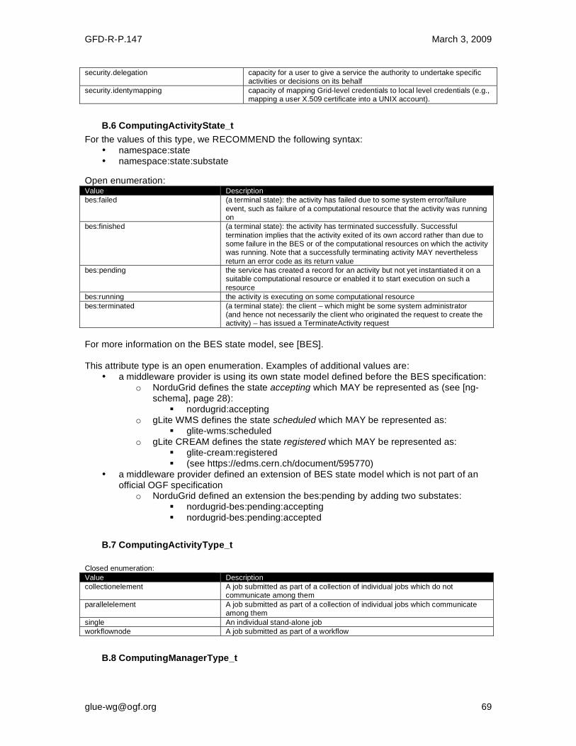
GFD-R-P.147 March 3, 2009
security.delegation capacity for a user to give a service the authority to undertake specific activities or decisions on its behalf
security.identymapping capacity of mapping Grid-level credentials to local level credentials (e.g., mapping a user X.509 certificate into a UNIX account).
B.6 ComputingActivityState_t
For the values of this type, we RECOMMEND the following syntax: • namespace:state • namespace:state:substate
Open enumeration: Value Description
bes:failed (a terminal state): the activity has failed due to some system error/failure
event, such as failure of a computational resource that the activity was running on
bes:finished (a terminal state): the activity has terminated successfully. Successful
termination implies that the activity exited of its own accord rather than due to some failure in the BES or of the computational resources on which the activity was running. Note that a successfully terminating activity MAY nevertheless
return an error code as its return value
bes:pending the service has created a record for an activity but not yet instantiated it on a suitable computational resource or enabled it to start execution on such a
resource
bes:running the activity is executing on some computational resource
bes:terminated (a terminal state): the client – which might be some system administrator (and hence not necessarily the client who originated the request to create the activity) – has issued a TerminateActivity request
For more information on the BES state model, see [BES]. This attribute type is an open enumeration. Examples of additional values are:
• a middleware provider is using its own state model defined before the BES specification: o NorduGrid defines the state accepting which MAY be represented as (see [ng-
schema], page 28): nordugrid:accepting
o gLite WMS defines the state scheduled which MAY be represented as: glite-wms:scheduled
o gLite CREAM defines the state registered which MAY be represented as: glite-cream:registered (see https://edms.cern.ch/document/595770)
• a middleware provider defined an extension of BES state model which is not part of an official OGF specification
o NorduGrid defined an extension the bes:pending by adding two substates: nordugrid-bes:pending:accepting nordugrid-bes:pending:accepted
B.7 ComputingActivityType_t
Closed enumeration: Value Description
collectionelement A job submitted as part of a collection of individual jobs which do not communicate among them
parallelelement A job submitted as part of a collection of individual jobs which communicate among them
single An individual stand-alone job
workflownode A job submitted as part of a workflow
B.8 ComputingManagerType_t
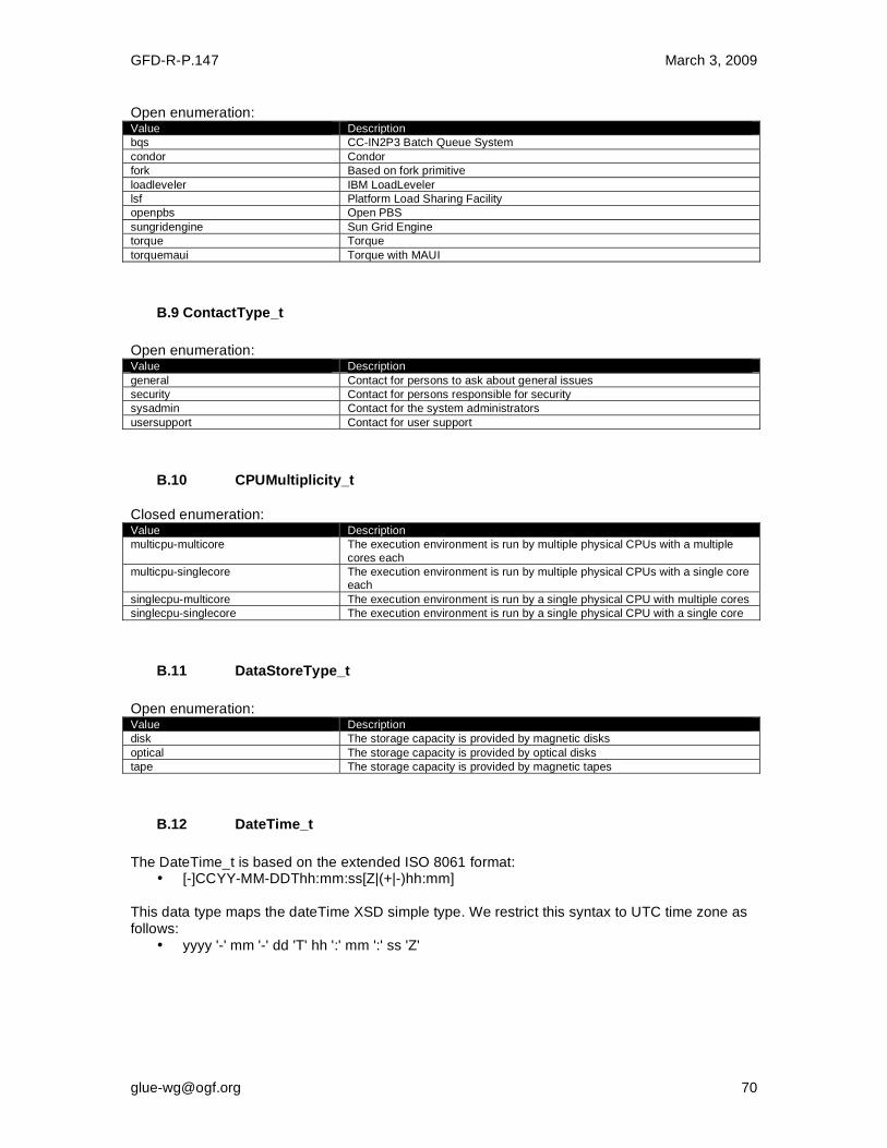
GFD-R-P.147 March 3, 2009
Open enumeration: Value Description
bqs CC-IN2P3 Batch Queue System
condor Condor
fork Based on fork primitive
loadleveler IBM LoadLeveler
lsf Platform Load Sharing Facility
openpbs Open PBS
sungridengine Sun Grid Engine
torque Torque
torquemaui Torque with MAUI
B.9 ContactType_t
Open enumeration: Value Description
general Contact for persons to ask about general issues
security Contact for persons responsible for security
sysadmin Contact for the system administrators
usersupport Contact for user support
B.10 CPUMultiplicity_t
Closed enumeration: Value Description
multicpu-multicore The execution environment is run by multiple physical CPUs with a multiple
cores each
multicpu-singlecore The execution environment is run by multiple physical CPUs with a single core each
singlecpu-multicore The execution environment is run by a single physical CPU with multiple cores
singlecpu-singlecore The execution environment is run by a single physical CPU with a single core
B.11 DataStoreType_t
Open enumeration: Value Description
disk The storage capacity is provided by magnetic disks
optical The storage capacity is provided by optical disks
tape The storage capacity is provided by magnetic tapes
B.12 DateTime_t
The DateTime_t is based on the extended ISO 8061 format:
• [-]CCYY-MM-DDThh:mm:ss[Z|(+|-)hh:mm] This data type maps the dateTime XSD simple type. We restrict this syntax to UTC time zone as follows:
• yyyy '-' mm '-' dd 'T' hh ':' mm ':' ss 'Z'

GFD-R-P.147 March 3, 2009
B.13 DN_t
Distinguished Name as defined by RFC 4514 (http://www.rfc-editor.org/rfc/rfc4514.txt). X.509 uses a X.500 namespace, represented as several Relative Domain-Names (RDNs) concatenated by forward-slashes. The final RDN is usually a single common name (CN), although multiple CNs are allowed.
B.14 EndpointHealthState_t
Closed enumeration: Value Description
critical It was possible to check the state of the endpoint and either it was not running or it was above some "critical" threshold
ok It was possible to check the state of the endpoint and it appeared to be
functioning properly
other It was possible to check the state of the endpoint, but this is not covered by the defined states
unknown It was not possible to check the state of the endpoint
warning It was possible to check the state of the endpoint, but it appeared to be above
some "warning" threshold or did not appear to be working properly
B.15 EndpointTechnology_t
Open enumeration: Value Description
corba The endpoint is implemented using CORBA technologies
jndi The endpoint is implemented using JNDI
webservice The endpoint is implemented as a Web Service
B.16 ExpirationMode_t
Closed enumeration: Value Description
neverexpire Support for files with infinite lifetime: they MAY only be removed by authorized
clients, not by the storage system itself
releasewhenexpired Support for files that have finite lifetimes and on expiration will be removed by the storage system
warnwhenexpired Support for files that have finite lifetimes, but on expiration cannot be removed by the storage system itself. The data content of an expired file MAY be deleted if it MAY be recovered from an archive. New store operations MAY
fail for certain clients until (some of the) expired files have either been removed by authorized clients, or have had their lifetimes increased
B.17 ExtendedBoolean_t
Closed enumeration: Value Description
false boolean false
true boolean true
undefined the value cannot be measured
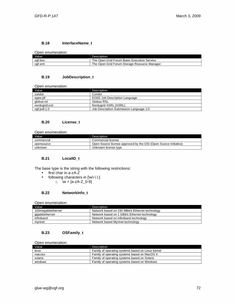
GFD-R-P.147 March 3, 2009
B.18 InterfaceName_t
Open enumeration: Value Description
ogf.bes The Open Grid Forum Basic Execution Service
ogf.srm The Open Grid Forum Storage Resource Manager
B.19 JobDescription_t
Open enumeration: Value Description
condor Condor
egee:jdl EGEE Job Description Language
globus:rsl Globus RSL
nordugrid:xrsl Nordugrid XSRL [XSRL]
ogf:jsdl:1.0 Job Description Submission Language 1.0
B.20 License_t
Open enumeration: Value Description
commercial Commercial license
opensource Open Source license approved by the OSI (Open Source Initiative)
unknown Unknown license type
B.21 LocalID_t
The base type is the string with the following restrictions:
• first char in a-zA-Z • following characters in [\w\-\.\:]
o \w = [a-zA-Z_0-9]
B.22 NetworkInfo_t
Open enumeration: Value Description
100megabitethernet Network based on 100 MBit/s Ethernet technology
gigabitethernet Network based on 1 GBit/s Ethernet technology
infiniband Network based on Infiniband technology
myrinet Network based Myrinet technology
B.23 OSFamily_t
Open enumeration: Value Description
linux Family of operating systems based on Linux kernel
macosx Family of operating systems based on MacOS X
solaris Family of operating systems based on Solaris
windows Family of operating systems based on Windows
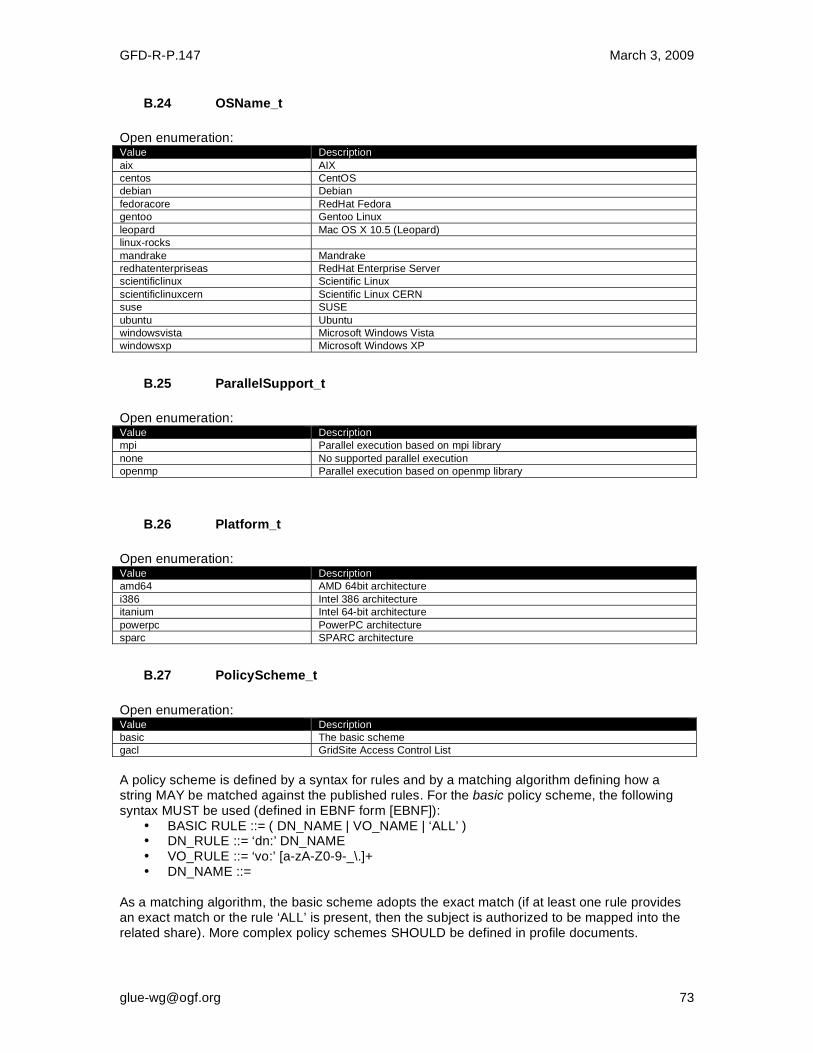
GFD-R-P.147 March 3, 2009
B.24 OSName_t
Open enumeration: Value Description
aix AIX
centos CentOS
debian Debian
fedoracore RedHat Fedora
gentoo Gentoo Linux
leopard Mac OS X 10.5 (Leopard)
linux-rocks
mandrake Mandrake
redhatenterpriseas RedHat Enterprise Server
scientificlinux Scientific Linux
scientificlinuxcern Scientific Linux CERN
suse SUSE
ubuntu Ubuntu
windowsvista Microsoft Windows Vista
windowsxp Microsoft Windows XP
B.25 ParallelSupport_t
Open enumeration: Value Description
mpi Parallel execution based on mpi library
none No supported parallel execution
openmp Parallel execution based on openmp library
B.26 Platform_t
Open enumeration: Value Description
amd64 AMD 64bit architecture
i386 Intel 386 architecture
itanium Intel 64-bit architecture
powerpc PowerPC architecture
sparc SPARC architecture
B.27 PolicyScheme_t
Open enumeration: Value Description
basic The basic scheme
gacl GridSite Access Control List
A policy scheme is defined by a syntax for rules and by a matching algorithm defining how a string MAY be matched against the published rules. For the basic policy scheme, the following syntax MUST be used (defined in EBNF form [EBNF]):
• BASIC RULE ::= ( DN_NAME | VO_NAME | ‘ALL’ ) • DN_RULE ::= ‘dn:’ DN_NAME • VO_RULE ::= ‘vo:’ [a-zA-Z0-9-_\.]+ • DN_NAME ::=
As a matching algorithm, the basic scheme adopts the exact match (if at least one rule provides an exact match or the rule ‘ALL’ is present, then the subject is authorized to be mapped into the related share). More complex policy schemes SHOULD be defined in profile documents.
GFD-R-P.147 March 3, 2009
Examples of policies expressed using the basic syntax are: • dn:/C=XX/O=YYYY/OU=Personal Certificate/L=ZZZZ/CN=NAME SURNAME
o matches the user proving to have a certificate identified by this DN • vo:/vo_a
o matches all the users proving to be part of the vo_a
B.28 QualityLevel_t
Closed enumeration: Value Description
development The component is under active development both in functionalities and interfaces
pre-production The component has completed the development and passed the testing phase; it is being used in real world scenarios
production The component completed the development and is considered stable for real world scenarios
testing The component has completed the development phase and is under testing
B.29 ReservationPolicy_t
Closed enumeration: Value Description
mandatory Jobs MUST be submitted only via advance reservation
none No reservation is supported
optional Jobs MAY be submitted via advance reservation, but this is not required
B.30 SchedulingPolicy_t
Open enumeration: Value Description
fairshare Statistically guarantees the allocated share
fifo First-In First-Out
random Random choice
B.31 ServiceType_t
The RECOMMENDED syntax is in reverse-DNS prefix. The first element is a top-level domain, while the second element is a namespace (the namespace MAY be related to a middleware name, an organization or other concepts; org.ogf.glue is reserved for the OGF GLUE Working Group). The defining body SHOULD have a claim on the corresponding forward DNS name (e.g., org.nordugrid.arex SHOULD be defined by the owners of the nordugrid.org domain name). Open enumeration: Value Description
org.ogf.glue* Prefix reserved for the OGF GLUE Working Group
org.glite.fts gLite File Transfer Service
org.glite.lb gLite Logging and Booking Service
org.glite.wms gLite Workload Management Service
org.nordugrid.arex NorduGrid Resource Coupled Execution Service
org.nordugrid.isis NorduGrid Information Index Service
org.nordugrid.storage NorduGrid Storage Service
org.teragrid gridftp TeraGrid GridFTP org.teragrid.condor-g TeraGrid Condor-g
org.teragrid.globus-mds4 TeraGrid Globus MDS 4 org.teragrid.gpfs TeraGrid GPFS org.teragrid.gsi-openssh TeraGrid gsi-enabled openssh org.teragrid.prewsgram TeraGrid pre-WS Globus GRAM org.teragrid.rft TeraGrid Reliable File Transfer org.teragrid.srb TeraGrid Storage Resource Broker org.teragrid.ws-delegation TeraGrid WS-Delegation Service

GFD-R-P.147 March 3, 2009
org.teragrid.ws-gram TeraGrid WS-GRAM Service org.teragrid.ws-ogsadai TeraGrid OGSA-DAI
B.32 ServingState_t
Closed enumeration: Value Description
closed The endpoint is not accepting request nor is serving them
draining The endpoint is not accepting requests, but is serving requests in the queue
production The endpoint is both accepting and serving requests
queueing The endpoint is accepting requests, but is not serving them
B.33 Staging_t
Closed enumeration: Value Description
none No staging of files supported
stagingin Automatic staging in of files supported
staginginout Automatic staging in and out of files supported
stagingout Automatic staging out of files supported
B.34 StorageAccessProtocol_t
Open enumeration: Value Description
afs Andrew File System protocol
dcap DCache access protocol
file POSIX access
gsidcap DCAP with GSI authentication
gsiftp FTP with GSI authentication
gsirfio RFIO with GSI authentication
http HyperText Transfer Protocol
https Secured HyperText Transfer Protocol
nfs Network File System protocol
rfio Remote File Input/Output protocol
root File transfer protocol for the ROOT framework
xrootd xrootd protocol
B.35 StorageCapacity_t
Open enumeration: Value Description
online Available storage capacity accessible in less than a minute in normal operating conditions
installedonline Online storage capacity including temporarily unavailable portions which would
be accessible in less than a minute in normal operating conditions
nearline Available storage capacity accessible in more than a minute and less than two days without human intervention in normal operating conditions
installednearline Nearline storage capacity including temporarily unavailable portions which would be accessible in more than a minute and less than two days without human intervention in normal operating conditions
offline Storage capacity possibly requiring human intervention for access in normal operating conditions
cache Storage capacity accessible in less than a minute used internally by the storage system and not directly exposed to the user

GFD-R-P.147 March 3, 2009
B.36 StorageManagerType_t
Open enumeration: Value Description
castor CERN Advanced STOrage manager, disk and tape management system
dcache Disk Cache, disk managing system with ability to control tape backends (e.g., Enstore)
enstore Tape Storage system, tape management system
gpfs General Parallel File System, disk management system
sse Smart Storage Element, disk management system
tsm IBM Tivoli Storage Manager, disk and tape management system
B.37 RetentionPolicy_t
Open enumeration: Value Description
custodial Low probability of loss
output An intermediate level and is appropriate for data which MAY be replaced by lengthy or effort-full processes
replica The highest probability of loss, but is appropriate for data for which a certain
amount of loss MAY be tolerated, in particular when other copies MAY be accessed in a timely fashion