glr225 - tiger officerimages.tigerofficer.com/manuals/bos-glr225-20141216010127535.pdf · glr225...
TRANSCRIPT

IMPORTANT: IMPORTANT : IMPORTANTE: Read Before Using Lire avant usage Leer antes de usar
Operating/Safety Instructions
Consignes de fonctionnement/sécurité
Instrucciones de funcionamiento y seguridad
1-877-BOSCH99 (1-877-267-2499) www.boschtools.com
Call Toll Free for Consumer Information& Service Locations
Pour obtenir des informationset les adresses de nos centres
de service après-vente,appelez ce numéro gratuit
Llame gratis paraobtener informaciónpara el consumidor y
ubicaciones de servicio
For English Version Version française Versión en español
See page 6 Voir page 25 Ver la página 43
GLR225

-2-
12
34
56
7
8
9
1011
1213
14
15
8
16
b c d ea
feg
h
i
i
i

-3-
1827
19
17
20
21
22
A
1.6 ft
1.6 ft
1.6 ft
1.6 ft
ED
CB

-4-
0.8 ft
2.4 ft
A
B3
B2
B1
A
B C
KJ
IH
GF

-5-
GLR225
DLA001
25
DLA002
26
6035961428
232609170085
24
1609203X36
19
1 609 203 X48
15
Rangefinder

-6-
LASER RADIATION. AVOIDDIRECT EYE EXPOSURE. DO NOT stareinto the laser light source. Never aim lightat another person or object other than theworkpiece. Laser light can damage your eyes.
Read all instructions. Failure to follow allinstructions listed below may result in electric
shock, fire and/or serious injury.
Do not direct the laser beam at persons or animals and donot stare into the laser beam yourself. This tool produceslaser class 2 laser radiation and complies with 21 CFR1040.10 and 1040.11 except for deviations pursuant to
Laser Notice No. 50, dated June 24, 2007. This can lead to personsbeing blinded.
General Safety Rules
! WARNING
Working safely with therangefinder is possible onlywhen the operating and safetyinformation are readcompletely and theinstructions contained therinare strictly followed. Nevermake warning labels on theRangefinder unrecognizable.
Never aim the beam at aworkpiece with a reflectivesurface. Bright shiny reflectivesheet steel or similar reflectivesurfaces are not recommendedfor laser use. Reflective surfacescould direct the beam backtoward the operator.
Take care to recognize theaccuracy and range of the device. Measurement may not
be accurate if used beyond therated range of the device.
Use of controls or adjustmentsor performance of proceduresother than those specifiedherein may result in hazardousradiation exposure.
The use of optical instrumentswith this product will increaseeye hazards.
Have the rangefinder repairedonly through qualifiedspecialist using original spareparts. This ensures that thesafety of the rangefinder is maintained.
Do not allow children to usethe rangefinder withoutsupervision. They could
Safety Rules for Rangefinder
! WARNING

-7-
unintentionally blind other persons.
Do not point the laser beam atpersons or animals and do notlook into the laser beamyourself, not even from a large distance.
Do not use the laser viewingglasses as safety goggles. Thelaser viewing glasses are used
for improved visualization of thelaser beam, but they do notprotect against laser radiation.
Do not use the laser viewingglasses as sun glasses or intraffic. The laser viewing glassesdo not afford complete UVprotection and reduce colorperception.
WARNING: Be sure to read andunderstand all instructions in thismanual before using this product.Failure to follow all instructionsmay result in hazardous radiationexposure, electric shock, fire,and/or bodily injury.
CAUTION: Use of controls oradjustments or performance ofprocedures other than thosespecified in this manual, may resultin hazardous radiation exposure.
CAUTION: The use of opticalinstruments with this product willincrease eye hazard.
IMPORTANT: The followinglabels are on your rangefinder foryour convenience and safety.They indicate where the laserlight is emitted by the level.ALWAYS BE AWARE of theirlocation when using the level.
ALWAYS: Make sure that anybystanders in the vicinity of useare made aware of the dangersof looking directly into the rangefinder.
DO NOT remove or deface anywarning or caution labels.
Removing labels increases the riskof exposure to laser radiation.
DO NOT stare directly at the laserbeam or project the laser beamdirectly into the eyes of others.Serious eye injury could result.
DO NOT place the rangefinder ina position that may cause anyoneto stare into the laser beamintentionally or unintentionally.Serous eye injury could result.
DO NOT use any optical toolssuch as, but not limited to,telescopes or transits to view thelaser beam. Serious eye injurycould result.
ALWAYS remove the batterieswhen cleaning the laser lightaperture to laser lens.
DO NOT operate the rangefinderaround children or allow childrento operate the rangefinder.Serious eye injury could result.
ALWAYS turn the rangefinder“OFF” when not in use. Leavingthe rangefinder “ON” increasesthe risk of someone inadvertentlystaring into the laser beam.
Safe Operating Procedures

DO NOT operate the rangefinderin combustible areas such as inthe presence of flammableliquids, gases or dust.
ALWAYS position the rangefindersecurely. Damage to therangefinder and/or serious injury tothe user could result if therangefinder falls.
ALWAYS use only the accessoriesthat are recommended by themanufacturer of your rangefinder.Use of accessories that have beendesigned for use with otherrangefinders could result in serious injury.
DO NOT leave rangefinder “on”unattended in any operation mode.
ALWAYS repair and servicingmust be performed by a qualifiedrepair facility. Repairs performedby unqualified personnel couldresult in serious injury.
DO NOT use this rangefinder forany purpose other than thoseoutlined in this manual. Thiscould result in serious injury.
DO NOT disassemble therangefinder. There are no userserviceable parts inside.Disassembling the laser will voidall warranties on the product. Donot modify the product in anyway. Modifying the rangefindermay result in hazardous laserradiation exposure.
-8-
Recycle raw materials & batteries instead of disposing of waste. Theunit, accessories, packaging & used batteries should be sorted forenvironmentally friendly recycling in accordance with the latest regulations.
WARNING: Batteries canexplode or leak, and can causeinjury or fire. To reduce this risk:
ALWAYS follow all instructionsand warnings on the battery labeland package.
DO NOT short any batteryterminals.
DO NOT charge alkaline batteries.
DO NOT mix old and newbatteries. Replace all of them at
the same time with new batteriesof the same brand and type.
DO NOT mix battery chemistries.
DISPOSE of batteries per localcode.
DO NOT dispose of batteries in fire.
KEEP batteries out of reach ofchildren.
REMOVE batteries if the devicewill not be used for several months.
Electrical Safety Procedures
Environment Protection

INTENDED USE
The rangefinder is intended formeasuring distances, lengths,heights, clearances and forcalculating areas and volumes.The rangefinder is suitable forinterior and exterior constructionsite measuring.
PRODUCT FEATURES
The numbering of the productfeatures shown refers to theillustration of the rangefinder onthe graphic page.
1 Reference point button2 Memory retrieve button”M=”3 Memory add button “M +”4 MIN., MAX. measurement button5 Length, area and volume measurement6 Vial level7 Display8 Alignment aid 9 Laser warning label10 Measurement button11 Indirect measurement and multi-surface area measurement button12 Memory subtraction button ”M –” 13 Continuous laser beam/change “unit of measure” button14 On/Off/Clear Button ”C”15 Extension pin16 Latch of the extension pin17 1/4” threaded hole for mounting optional tripod*
18 Latch of battery lid 19 Battery lid20 Serial number label 21 Laser beam outlet 22 Reception lens23 Protective case24 Hand strap25 Laser viewing glasses*26 Laser target plate*27 Hand strap mounting post
DISPLAY ELEMENTS
a Measured values storedb Battery indicationc Problem temperature indicatord Measured value/resulte Unit of measuref Measurement reference pointg Laser switched onh Individual measured value (for length measurement: result)i Measure mode indicators Length measurement Area measurement Volume measurement Indirect length measurement
Wall surface measurementMinimum measurementMaximum measurement
* Optional Accessories
-9-
Functional Description
MINMAX
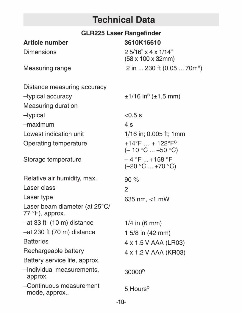
Article number
Dimensions
Measuring range
Distance measuring accuracy
–typical accuracy
Measuring duration
–typical
–maximum
Lowest indication unit
Operating temperature
Storage temperature
Relative air humidity, max.
Laser class
Laser type
Laser beam diameter (at 25°C/77 °F), approx.
–at 33 ft (10 m) distance
–at 230 ft (70 m) distance
Batteries
Rechargeable battery
Battery service life, approx.
–Individual measurements, approx.
–Continuous measurement mode, approx..
3610K16610
2 5/16” x 4 x 1/14” (58 x 100 x 32mm)
2 in ... 230 ft (0.05 ... 70mA)
±1/16 inB (±1.5 mm)
<0.5 s
4 s
1/16 in; 0.005 ft; 1mm
+14°F … + 122°FC
(– 10 °C ... +50 °C)
– 4 °F ... +158 °F(–20 °C ... +70 °C)
90 %
2
635 nm, <1 mW
1/4 in (6 mm)
1 5/8 in (42 mm)
4 x 1.5 V AAA (LR03)
4 x 1.2 V AAA (KR03)
30000D
5 HoursD
-10-
GLR225 Laser Rangefinder
Technical Data
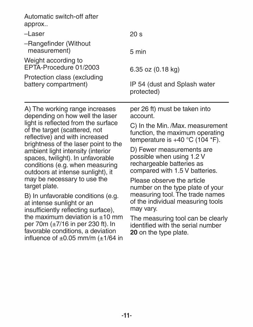
Automatic switch-off afterapprox..
–Laser
–Rangefinder (Without measurement)
Weight according toEPTA-Procedure 01/2003
Protection class (excludingbattery compartment)
20 s
5 min
6.35 oz (0.18 kg)
IP 54 (dust and Splash waterprotected)
-11-
A) The working range increasesdepending on how well the laserlight is reflected from the surfaceof the target (scattered, notreflective) and with increasedbrightness of the laser point to theambient light intensity (interiorspaces, twilight). In unfavorableconditions (e.g. when measuringoutdoors at intense sunlight), itmay be necessary to use thetarget plate.
B) In unfavorable conditions (e.g.at intense sunlight or aninsufficiently reflecting surface),the maximum deviation is ±10 mmper 70m (±7/16 in per 230 ft). Infavorable conditions, a deviationinfluence of ±0.05 mm/m (±1/64 in
per 26 ft) must be taken intoaccount.
C) In the Min. /Max. measurementfunction, the maximum operatingtemperature is +40 °C (104 *F).
D) Fewer measurements arepossible when using 1.2 Vrechargeable batteries ascompared with 1.5 V batteries.
Please observe the articlenumber on the type plate of yourmeasuring tool. The trade namesof the individual measuring toolsmay vary.
The measuring tool can be clearlyidentified with the serial number20 on the type plate.
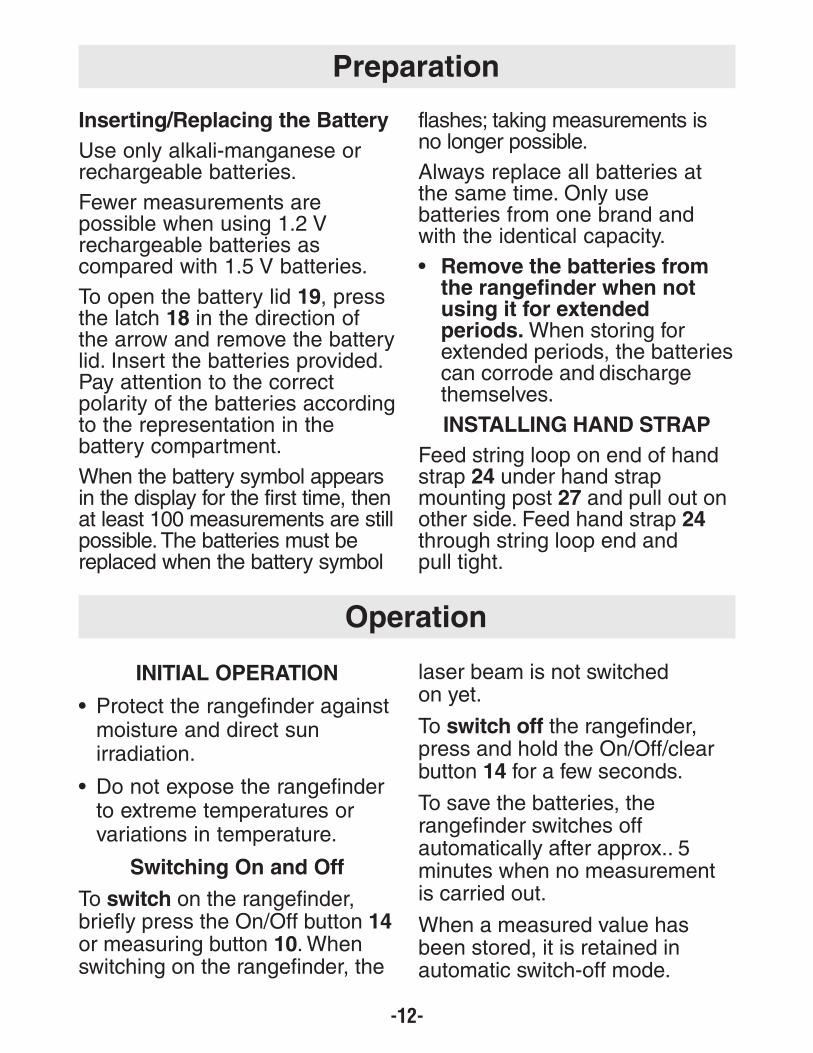
INITIAL OPERATION
• Protect the rangefinder against moisture and direct sun irradiation.
• Do not expose the rangefinder to extreme temperatures or variations in temperature.
Switching On and Off
To switch on the rangefinder,briefly press the On/Off button 14or measuring button 10. Whenswitching on the rangefinder, the
laser beam is not switched on yet.
To switch off the rangefinder, press and hold the On/Off/clear button 14 for a few seconds.
To save the batteries, therangefinder switches offautomatically after approx.. 5minutes when no measurementis carried out.
When a measured value hasbeen stored, it is retained inautomatic switch-off mode.
-12-
Inserting/Replacing the Battery
Use only alkali-manganese orrechargeable batteries.
Fewer measurements arepossible when using 1.2 Vrechargeable batteries ascompared with 1.5 V batteries.
To open the battery lid 19, pressthe latch 18 in the direction ofthe arrow and remove the batterylid. Insert the batteries provided.Pay attention to the correctpolarity of the batteries accordingto the representation in thebattery compartment.
When the battery symbol appearsin the display for the first time, then at least 100 measurements are stillpossible. The batteries must bereplaced when the battery symbol
flashes; taking measurements isno longer possible.
Always replace all batteries atthe same time. Only usebatteries from one brand andwith the identical capacity.
• Remove the batteries from the rangefinder when not using it for extended periods.When storing for extended periods, the batteries can corrode and discharge themselves.
INSTALLING HAND STRAP
Feed string loop on end of handstrap 24 under hand strapmounting post 27 and pull out onother side. Feed hand strap 24through string loop end and pull tight.
Preparation
Operation

-13-
When switching on therangefinder again, “M” isindicated in the display.
Measuring Procedure
The rangefinder offers a varietyof different measuring modes thatcan be selected by pushing the
corresponding mode button (see“Measuring Mode”). Afterswitching on, the rangefinder is inthe “length measurement mode”.
Also, it is possible to select any ofthe four different reference pointsfor the measurement by pushingthe reference point button 1 (see“Selecting the Reference Point”).After switching on, the rear edgeof the rangefinder is preset as thereference point.
Upon selection of the measuringmode and the reference point, allfurther steps are carried out bypushing the measuring button 10.
With the reference level selected,place the rangefinder against thedesired measuring line (e.g. a wall).
Push the measuring button 10 toswitch on the laser beam.
Do not point thelaser beam at persons oranimals and do not look intothe laser beam yourself, noteven from a large distance.
Aim the laser beam at the targetsurface. Push the measuringbutton 10 again to initiate themeasurement.
In the continuous laser beammode, the measurement alreadystarts upon first actuation of themeasuring button 10.
The measured value appearsafter 0.5 to 4 seconds. Theduration of the measurementdepends on the distance, thelight conditions and the reflectionproperties of the target surface.The end of the measurement isindicated by a signal tone. Thelaser beam is switched offautomatically upon completion ofthe measurement.
When no measurement hastaken place approx.. 20 secondsafter sighting, the laser beam isswitched off automatically to savethe batteries.
Selecting the Reference Point(see figures B–E)
For measuring, it is possible toselect from four different reference points:
• the rear edge of the rangefinder (e.g., when placing the measuring rangefinder flush against a wall),
• the rear edge of the extension pin 15 (e.g., for measurements out of corners).
• the front edge of the rangefinder (e.g., as when measuring from the edge of a table onward),
• the center of the 1/4” threaded hole 17 (e.g., for measuring with the tripod).
! WARNING
-14-
To select the reference point,push button 1 repeatedly until therequired reference point is indicated in the display. Eachtime after switching on, the rearedge of the rangefinder is presetas the reference point.
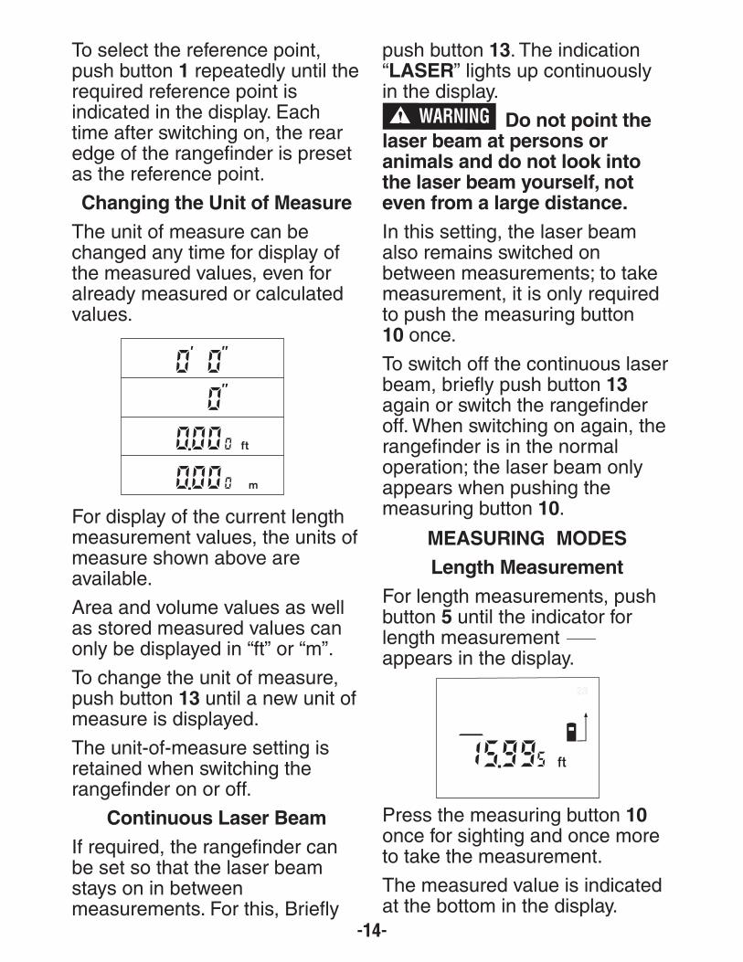
Changing the Unit of Measure
The unit of measure can bechanged any time for display ofthe measured values, even foralready measured or calculatedvalues.
For display of the current lengthmeasurement values, the units ofmeasure shown above areavailable.
Area and volume values as wellas stored measured values canonly be displayed in “ft” or “m”.
To change the unit of measure,push button 13 until a new unit ofmeasure is displayed.
The unit-of-measure setting isretained when switching therangefinder on or off.
Continuous Laser Beam
If required, the rangefinder canbe set so that the laser beamstays on in betweenmeasurements. For this, Briefly
push button 13. The indication“LASER” lights up continuouslyin the display.
Do not point the laser beam at persons oranimals and do not look intothe laser beam yourself, noteven from a large distance.
In this setting, the laser beamalso remains switched on between measurements; to takemeasurement, it is only requiredto push the measuring button 10 once.
To switch off the continuous laserbeam, briefly push button 13again or switch the rangefinderoff. When switching on again, therangefinder is in the normaloperation; the laser beam onlyappears when pushing themeasuring button 10.
MEASURING MODES
Length Measurement
For length measurements, pushbutton 5 until the indicator forlength measurementappears in the display.
Press the measuring button 10once for sighting and once moreto take the measurement.
The measured value is indicatedat the bottom in the display.
! WARNING

-15-
Area Measurement
For area measurements, pushbutton 5 until the indicator forarea measurementappears in the display.
Afterwards, measure the lengthand the width, one after another,in the same manner as a lengthmeasurement. The laser beamremains switched on betweenboth measurements.
After taking the second measurement, the area isautomatically calculated and displayed. The last individualmeasured value is indicated atthe bottom in the display, whilethe final result is shown at the top.
Volume Measurement
For volume measurements, pushbutton 5 until the indicator for volume measurement appears in the display.
Afterwards, measure the length,width and the height, one afteranother, in the same manner asfor a length measurement. Thelaser beam remains switched onbetween all three measurements.
After taking the third measurement, the volume is automatically calculated and displayed. The last individualmeasured value is indicated atthe bottom in the display, whilethe final result is shown at the top.
Values above 999990 ft3 cannotbe displayed; “Error” and “- - - -”appear on the display. In thiscase, switch the unit of measureto meters (see “Changing theUnit of Measure”, page 14).
Area or Volume Rounding ofLarge Calculations
For values larger than 9999 feetor meters the rangefinder roundsthe calculated value to thenearest 10 feet or 10 meters.Accuracy in such situations isalways 99.95% or better.
Minimum Measurement (see figure F)
The minimum measurement isused to determine the shortestdistance from a fixed referencepoint. It is used, as an example,for determining plumb lines orhorizontal partitions.
For minimum measurements,press button 4 until “MIN”appears in the display.

-16-
To start the measurement, brieflypush the measuring button 10.
Move the laser back and forthover the requested target (e.g.,the room ceiling for determiningthe plumb line) in such a mannerthat the reference point of themeasurement (e.g., the tip of theextension pin 15) always remains at the same location.
During the measurement, thecurrent length measurementvalue is indicated at the bottom ofthe display.
The minimum value is indicatedat the top right in the display. It isalways overwritten, when the current length measurementvalue is lower than the presentminimal value.
To end the minimummeasurement, briefly push themeasuring button 10. Pushing themeasuring button again starts anew measurement.
Maximum Measurement (see figure G)
The maximum measurement isused to determine the greatestdistance from a fixed referencepoint. It is used, as an example,for determining diagonals.
For maximum measurements,
push button 4 until “MAX” appears in the display.
To start the measurement, brieflypush the measuring button 10.
Move the laser back and forthover the requested target (e.g.,the room corner for determiningthe diagonal) in such a mannerthat the reference point of themeasurement (e.g., the tip of theextension pin 15) always remains at the same location.
During the measurement, thecurrent length measurementvalue is indicated at the bottom ofthe display.The minimum value isindicated at the top right in thedisplay. It is always overwritten,when the current length measurement value is larger thanthe present maximal value.
To end the maximum measurement, briefly push themeasuring button 10. Pushing themeasuring button again starts anew measurement.
Indirect Length Measurement(see figure H)
The indirect length measurementis used to measure distancesthat cannot be measured directlybecause an obstacle would obstruct the laser beam or no
-17-
target surface is available as areflector. Correct results areachieved only when the laserbeam and the sought distanceform an exact right angle (90°)(Pythagorean Theorem).
In the illustrated example, thelength B is to be determined. Forthis purpose, A and C must bemeasured. A and B must form aright angle.
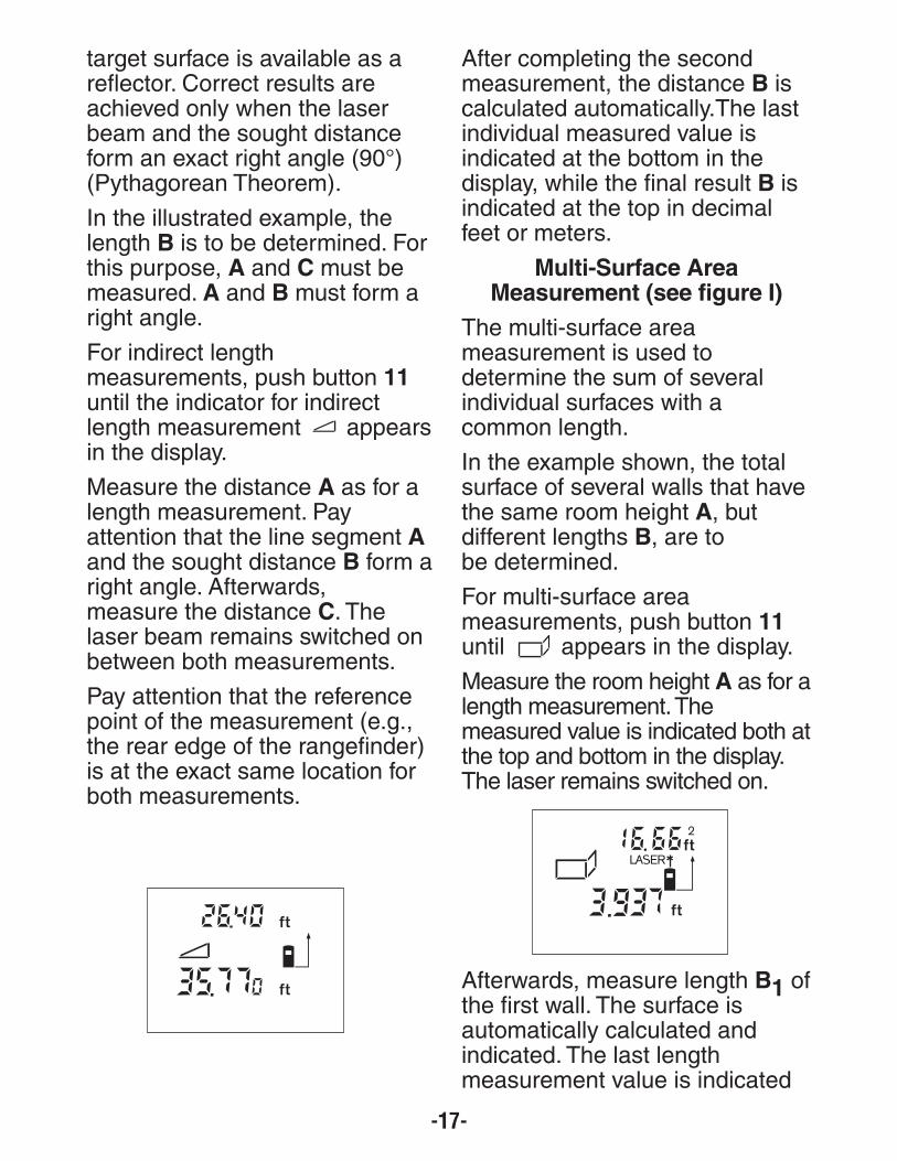
For indirect length measurements, push button 11until the indicator for indirectlength measurement appearsin the display.
Measure the distance A as for alength measurement. Pay attention that the line segment Aand the sought distance B form aright angle. Afterwards, measure the distance C. Thelaser beam remains switched onbetween both measurements.
Pay attention that the referencepoint of the measurement (e.g.,the rear edge of the rangefinder)is at the exact same location forboth measurements.
After completing the secondmeasurement, the distance B iscalculated automatically.The lastindividual measured value isindicated at the bottom in thedisplay, while the final result B isindicated at the top in decimalfeet or meters.
Multi-Surface AreaMeasurement (see figure I)
The multi-surface areameasurement is used todetermine the sum of severalindividual surfaces with acommon length.
In the example shown, the totalsurface of several walls that havethe same room height A, but different lengths B, are to be determined.
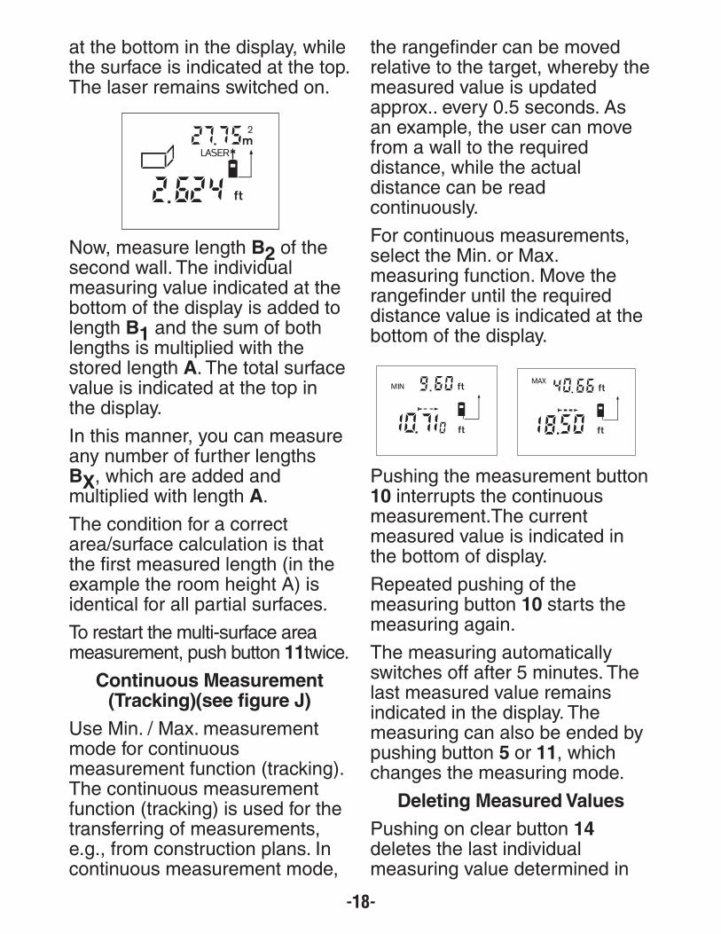
For multi-surface areameasurements, push button 11until appears in the display.
Measure the room height A as for alength measurement. Themeasured value is indicated both atthe top and bottom in the display.The laser remains switched on.
Afterwards, measure length B1 ofthe first wall. The surface is automatically calculated and indicated. The last length measurement value is indicated
-18-
at the bottom in the display, whilethe surface is indicated at the top.The laser remains switched on.
Now, measure length B2 of thesecond wall. The individual measuring value indicated at thebottom of the display is added tolength B1 and the sum of bothlengths is multiplied with thestored length A. The total surfacevalue is indicated at the top in the display.
In this manner, you can measureany number of further lengthsBX, which are added and multiplied with length A.
The condition for a correctarea/surface calculation is thatthe first measured length (in theexample the room height A) isidentical for all partial surfaces.
To restart the multi-surface areameasurement, push button 11twice.
Continuous Measurement (Tracking)(see figure J)
Use Min. / Max. measurementmode for continuousmeasurement function (tracking).The continuous measurementfunction (tracking) is used for thetransferring of measurements,e.g., from construction plans. Incontinuous measurement mode,
the rangefinder can be movedrelative to the target, whereby themeasured value is updated approx.. every 0.5 seconds. Asan example, the user can movefrom a wall to the requireddistance, while the actualdistance can be readcontinuously.
For continuous measurements,select the Min. or Max.measuring function. Move therangefinder until the requireddistance value is indicated at thebottom of the display.
Pushing the measurement button10 interrupts the continuousmeasurement.The currentmeasured value is indicated inthe bottom of display.
Repeated pushing of themeasuring button 10 starts themeasuring again.
The measuring automaticallyswitches off after 5 minutes. Thelast measured value remainsindicated in the display. Themeasuring can also be ended bypushing button 5 or 11, whichchanges the measuring mode.
Deleting Measured Values
Pushing on clear button 14deletes the last individualmeasuring value determined in

-19-
all measuring functions. Pushingthe button repeatedly deletes theindividual measured values inreverse order.
In the multi-surface areameasurement mode, pushingbutton 14 the first time deletesthe last individually measuredvalue; pushing the button asecond time deletes all lengths BX.
Memory Modes
When switching off the Rangefinder, the value in thememory is retained.
In the multi-surface area measur-ement mode, the total surfacevalue can be stored; in theminimum and maximummeasuring mode, the minimumand maximum value can be storedcorrespondingly. Storing individualmeasuring values within thesefunctions is not possible.
Storing/Adding Measured Values
Push the memory add button 3 inorder to store the currentmeasured value – a length, areaor volume value, depending onthe current measuring function.As soon as a value has beenstored, “M” is indicated in the
display and “add” is brieflyindicated next to it.
If a value is already stored in thememory, the new value is addedto the memory contents,however, only if it’s the same typeof measurement.
As an example, when an areavalue is in the memory and thecurrent measured value is a volume value, the addition cannottake place. “Error” briefly flashesin the display.
However, values of the sametype (e.g. length values) can beadded no matter if they havebeen measured in feet andinches, decimal feet or meters.
Subtracting Measured Values
Push the memory subtractionbutton 12 in order to subtract thecurrent measured value from thememory value. As soon as avalue has been subtracted, “M”is indicated in the display and isbriefly followed by “SUB”.
If a value is already stored in thememory, the new measuredvalue can be subtracted onlywhen the measures of unit correspond (see “Storing/AddingMeasured Values”).

-20-
Displaying the Stored Value
Push the memory retrieve button2 in order to display the valuestored in the memory. “M=” is indicated in the display. When thememory contents “M=” is indicated in the display, it can bedoubled by pushing the memoryadd button 3 or set to zero bypushing the memory subtractbutton 12.
The memorized values can onlybe displayed in decimal feet or meters.
Deleting the Memory
To delete the memory contents,first push the memory retrievebutton 2, so that “M=” is indicated in the display. Thenpush the clear button 14; “M” isno longer indicated in the display.
The reception lens 22 and thelaser beam outlet 21 must not becovered when taking a measurement.
The rangefinder must not bemoved while taking ameasurement (with the exceptionof the continuous measurementmode). Therefore, wheneverpossible, place the rangefinderagainst or on the measuringpoints.
Measurement takes place at thecenter of the laser beam, evenwhen target surfaces are sightedat an incline.
The measuring range dependsupon the light conditions and thereflection properties of the target surface. For improved visibility ofthe laser beam when workingoutdoors and when the sunlight is intense, use the laser viewingglasses 25 and the laser targetplate 26, or shade off thetarget surface.
When measuring againsttransparent surfaces (e.g. glass,water) or reflecting surfaces,faulty measurements arepossible. Also, porous orstructured surfaces, air layers
Operating Instructions

-21-
with varying temperatures orindirectly received reflections canaffect the measured value. Theseeffects are due to physicalreasons and can therefore not be compensated for by therangefinder.
Sighting with the Alignment Aid(see figure K)
With the alignment aid 8, sightingover larger distances is a loteasier. For this, look alongsidethe aligning aid on the top side ofthe rangefinder. The laser beamruns parallel to this line of sight.
Measuring with the ExtensionPin (see figures C and G)
The extension pin 16 is suitablefor measuring from insidecorners (to measure diagonals)or from hard to reach areas, suchas from roller-shutter rails.
Slide the latch 16 of theextension pin sideward in order toswivel out the pin.
Set the corresponding referencepoint for measurements with theextension pin by pushing button 10.
The extension pin 16 swivels backin again by pushing it toward thehousing to the stop. The pinautomatically locks in place.
Aligning with the Vial Level
The vial level 6 allows for simpleleveling of the rangefinder. Thisallows for easier sighting of target
surfaces, especially over longerdistances.
In combination with the laser beam, the vial level 6 is not suitable for leveling.
Working with Tripod
The use of a tripod (not included)is particularly advisable for largerdistances because of thesteadiness it provides. Therangefinder tool can be screwedonto a commercially availabletripod using the 1/4" thread 17 onthe bottom side of the housing.
Set the corresponding referencepoint for measurement with atripod by pushing button 10 (thereference point is the center of thread).

-22-
Trouble Shooting
Issue Remedy
The indications “Hot” or “Cold” are indicated in the display;measurement not possible.
The rangefinder is not within theoperating temperature of – 10 °C to+50 °C (+14 °F to +122 °F).
Wait until the rangefinder hasreached the operating temperature
Battery indication “B” is indicated
Battery voltage decreasing(measurement still possible)
Replace batteries
Battery indication a flashes, measurement not possible
Battery voltage too low Replace batteries
The indications “Error.” and “- - -” are indicated in the display
The angle between the laser beamand the target is too acute.
Enlarge the angle between the laserbeam and the target
The target surface reflects toointensely (e.g. a mirror) orinsufficiently (e.g. black fabric), orthe ambient light is too bright
Work with the laser target plate 25(optional accessory)
The laser beam outlet 21 or thereception lens 22 are misted up(e.g. due to a rapid temperaturechange).
Wipe the laser beam outlet 21and/or the reception lens 22 dryusing a soft cloth
The calculated area or volume valueis larger than 99990 ft2 or ft3.
Change unit of measure to “m”
The indication “Error.” flashes at the top in the display
Addition/Subtraction of differenttypes of measurements
Only add/subtract of the same type
Unreliable measuring result
The target surface does not reflectcorrectly (e.g. water, glass).
Cover off the target surface
The laser beam outlet 21 or thereception lens 22 are covered.
Make sure that the laser beamoutlet 21 or the reception lens 22are unobstructed

-23-
The rangefindermonitors the correctmode for eachmeasurement. Whena defect is
determined, only the symbolshown aside flashes in the display.
Accuracy Check of theRangefinder
The accuracy of the rangefindercan be checked as follows:• Select a permanently
unchangeable measuring
section with a length of approx.. 3 to 10 meters (10 to 33 feet); its length must be precisely known (e.g. the width of a room or a door opening).
• Measure the distance 10 times after another.
The difference in values must notamount to more than a maximumof ±2.0 mm (±1/8 in). Keep arecord of the measurements inorder to compare the accuracy at a later time.
Issue Remedy
Measuring result not plausible
Wrong reference point set Select reference point thatcorresponds to measurement
Obstruction in path of laser beam Laser point must be completely ontarget surface
Store and transport therangefinder only in the suppliedprotective case.
Keep the rangefinder clean at alltimes.
Do not immerse the rangefinderinto water or other fluids.
Wipe off debris using a moist andsoft cloth.
Do not use any cleaning agentsor solvents.
Maintain the reception lens 22 inparticular, with the same care as required for eye glasses or thelens of a camera.
In all correspondence and spareparts orders, please always include the 10-digit article number given on the type plate of the rangefinder.
In case of repairs, send in therangefinder packed in itsprotective case 23.
Maintenance and Service
DISPOSAL
Rangefinders, batteries, accessories and packaging should be sortedfor environmental-friendly recycling.

-24-
LIMITED WARRANTY OF BOSCH LASER AND MEASURING TOOL PRODUCTS
Robert Bosch Tool Corporation ("Seller") warrants to the original purchaser only, that all BOSCH laser
and measuring tool products will be free from defects in material or workmanship for a period of three
(3) years from date of purchase.
SELLER'S SOLE OBLIGATION AND YOUR EXCLUSIVE REMEDY under this Limited Warranty and, to
the extent permitted by law, any warranty or condition implied by law, shall be the repair or replacement
of laser and measuring tool products, which are defective in material or workmanship and which have
not been misused, carelessly handled, or misrepaired by persons other than Seller or Seller Authorized
Service providers.
SELLER'S OBLIGATION AND YOUR REMEDY ARE FURTHER LIMITED AS FOLLOWS:
• 30-Day Money Back Refund or Replacement. If you are not completely satisfied with the
performance of your laser or measuring tool product, for any reason, you can return it to BOSCH within
30 days of the date of purchase for a full refund or replacement. To obtain this 30-Day Refund or
Replacement, your return must be accompanied by the original receipt for purchase of the laser or
measuring tool product. A maximum of 2 returns per customer will be permitted.
• First Year– OTC Warranty. BOSCH will replace your laser or measuring tool product that has failed
when used in conformance with product instructions and warnings, with a new laser or measuring tool
product of comparable features, for free, any time during the first year after purchase. This warranty
does not apply if your laser or measuring tool product fails solely due to the need for recalibration.
• 2- and 3-Year Exchange. BOSCH will replace your laser or measuring tool product that has failed
when used in conformance with product instructions and warnings, with a new or reconditioned laser or
measuring tool product of comparable features, for an exchange cost. This warranty does not apply if
your laser or measuring tool product fails solely due to the need for recalibration.
For details to make a claim under this Limited Warranty please visit www.boschtools.com or
call 1-877-267-2499.
ANY IMPLIED WARRANTIES SHALL BE LIMITED IN DURATION TO ONE YEAR FROM DATE OF
PURCHASE. SOME STATES IN THE U.S., AND SOME CANADIAN PROVINCES DO NOT ALLOW
LIMITATIONS ON HOW LONG AN IMPLIED WARRANTY LASTS, SO THE ABOVE LIMITATION MAY
NOT APPLY TO YOU.
IN NO EVENT SHALL SELLER BE LIABLE FOR ANY INCIDENTAL OR CONSEQUENTIAL DAMAGES
(INCLUDING BUT NOT LIMITED TO LIABILITY FOR LOSS OF PROFITS) ARISING FROM THE SALE
OR USE OF THIS PRODUCT. SOME STATES IN THE U.S., AND SOME CANADIAN PROVINCES DO
NOT ALLOW THE EXCLUSION OR LIMITATION OF INCIDENTAL OR CONSEQUENTIAL DAMAGES,
SO THE ABOVE LIMITATION MAY NOT APPLY TO YOU.
THIS LIMITED WARRANTY GIVES YOU SPECIFIC LEGAL RIGHTS, AND YOU MAY ALSO HAVE
OTHER RIGHTS WHICH VARY FROM STATE TO STATE IN THE U.S., OR PROVINCE TO PROVINCE
IN CANADA AND FROM COUNTRY TO COUNTRY.
THIS LIMITED WARRANTY APPLIES ONLY TO PRODUCTS SOLD WITHIN THE UNITED STATES OF
AMERICA, CANADA AND THE COMMONWEALTH OF PUERTO RICO. FOR WARRANTY
COVERAGE WITHIN OTHER COUNTRIES, CONTACT YOUR LOCAL BOSCH DEALER OR
IMPORTER.