globe control valve - mountain states engineering and controls · gls globe control valve 3...
TRANSCRIPT

GLSGlobe
Control Valve
Mountain States Engineering and Controls | 303-232-4100 | www.mnteng.com

2 GL S GLOBE CONTROL VALVE
I N T R O D U C T I O N
The GLS Series is recognized as a high-per-formance control valve in the oil, gas, power, and process industries, the while boasting easy, quick, and economical maintenance. In contrast from other control valves operated by spring-diaphragm actuators, the GLS Series is operated by double acting spring-cylinder actuator that takes advantage of its high pneumatic stiffness, which in turn ensures an excellent and accurate positioning in throttling as well as fast and reliable response to changes in the control signal. As the actuator operates with air supply pressure up to 150 psi (10.3 bar), the GLS Series provides the required force to ensure that the specified shutoff class, even under high differential pressures, is achieved
While the spring-diaphragm actuators depend entirely on spring force to close a valve, the GLS Series control valves combines spring force, air supply pressure, process fluid pressure, and its self-centering seat design to produce a high closing force, thus ensiring a high level of tightness.
One of the most common applications challenges associated with control valves is attributed to the selection of cage-guided systems. The close contact between the metallic surfaces of the seat retainer (cage) and the plug frequently results in friction wear and jamming. It is for this reasonthat the GLS Series has a double upper guide system that is located outside the flow path and completely eliminates direct contact between the plug and the seat retainer.
The double acting spring-cylinder actuator manufactured by PetrolValve for the GLS Series control valves has a light, compact construction, and permits easy handling when compared with conventional spring-diaphragm actuators.
Due to advancements in its globe-type design and actuator sturdiness and performance, the GLS Series sets the for control valves its category around the world today.
GLS SERIES – BODY SUB-ASSEMBLY (FIGURE 1)
Rangeability 30:1 (Typical)
ANSI Class IV Shutoff – Metal Seat *ANSI Class VI Shutoff – Soft Seat *
*Standard for valves with unbalanced trim.
Top Entry Assembly:Quick and Easy Maintenance
Double Upper Guide System:
out of Flow Passageway
Self-Centerering Seat: Excellent Shutoff Ability;
No Special Tools Required
Mountain States Engineering and Controls | 303-232-4100 | www.mnteng.com
GL S GLOBE CONTROL VALVE 3
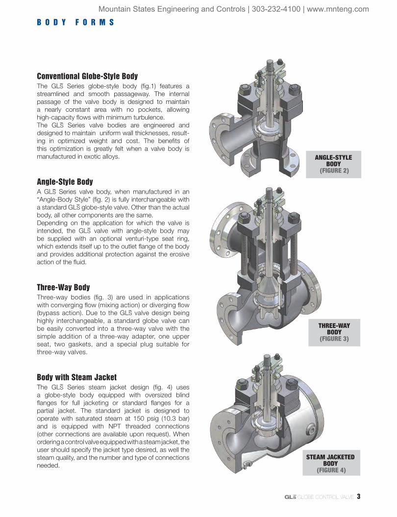
Conventional Globe-Style BodyThe GLS Series globe-style body (fig.1) features a streamlined and smooth passageway. The internal passage of the valve body is designed to maintain a nearly constant area with no pockets, allowing high-capacity flows with minimum turbulence.The GLS Series valve bodies are engineered and designed to maintain uniform wall thicknesses, result-ing in optimized weight and cost. The benefits of this optimization is greatly felt when a valve body is manufactured in exotic alloys.
Angle-Style BodyA GLS Series valve body, when manufactured in an “Angle-Body Style” (fig. 2) is fully interchangeable with a standard GLS globe-style valve. Other than the actual body, all other components are the same.Depending on the application for which the valve is intended, the GLS valve with angle-style body may be supplied with an optional venturi-type seat ring, which extends itself up to the outlet flange of the body and provides additional protection against the erosive action of the fluid.
Three-Way BodyThree-way bodies (fig. 3) are used in applications with converging flow (mixing action) or diverging flow (bypass action). Due to the GLS valve design being highly interchangeable, a standard globe valve can be easily converted into a three-way valve with the simple addition of a three-way adapter, one upper seat, two gaskets, and a special plug suitable for three-way valves.
Body with Steam JacketThe GLS Series steam jacket design (fig. 4) uses a globe-style body equipped with oversized blind flanges for full jacketing or standard flanges for a partial jacket. The standard jacket is designed to operate with saturated steam at 150 psig (10.3 bar) and is equipped with NPT threaded connections (other connections are available upon request). When ordering a control valve equipped with a steam jacket, the user should specify the jacket type desired, as well the steam quality, and the number and type of connections needed.
B O D Y F O R M S
ANGLE-STYLE BODY
(FIGURE 2)
THREE-WAY BODY
(FIGURE 3)
STEAM JACKETED BODY
(FIGURE 4)
Mountain States Engineering and Controls | 303-232-4100 | www.mnteng.com

4 GL S GLOBE CONTROL VALVE
C H A R A C T E R I S T I C S , A D V A N T A G E S
RuggedThe GLS valve construction makes it less prone to corrosion attacks from process fluids when compared to conventional globe valves.
The rugged plug stem, as well as other valve components, are designed for heavy-duty service and can withstand high differential pressures.
Valves equipped with separable flanges (up to 3 inches)comply with all application ranges covered by ANSI Class 600 by means of a simple change of the process connection flanges.
When necessary, optional low-noise and anti-cavitation trim are also available, making the GLS an ideal choice for severe service applications.
SeatingIn addition to providing accurate control, the concept of the GLS valve with a single and self-centering seat ensures exceptional shutoff capability, normally assisted by the fluid pressure. In normal conditions, along with the air supply, the double acting spring-cylinder actuator ensures a high seating force; and in the event of an air supply loss, the actuator spring plus the resulting force from fluid pressure move the plug to the required fail-safe position.
Quick and Easy Maintenance PetrolValve’s top-entry assembly design simplifies maintenance tasks. Once the bonnet flange nuts are removed, the bonnet and plug can be easily removed from the valve body, allowing access to other internal components.
The clamped-in seat ring, secured by the seat retainer, as well as all other components of the valve and the actuator, do not require the use of special tools for their its disassembly or assembly.
The compact size of the valve and its low weight help its handling for maintenance and installation.
Guiding and PackingThe GLS Series guiding system deserves special recognition, since not only does it eliminate the disadvantages of a guiding system at the seat retainer but the GLS guides, being well spaced and with large bearing support surfaces, eliminate problems related to vibration in control valves.
Due to the use of this advanced guiding system, the rugged plug stem of the GLS valve may be subjected to twice the thrust produced by available oversized actuators, without the risk of buckling.
The depth of the GLS Series packing box allows the use of all packing options offered by PetrolValve, and the excellent surface finish of the bonnet bore and the plug stem contributes for a long packing life, with no leakage.
Non-Jamming TrimThe double upper guide system, located out of the flow passageway, assures a perfect alignment of the plug stem, while providing consi derable clearance between the plug head and the seat retainer, eliminating friction problems related to the guiding system in the seat retainer (cage-guided designs).
VersatileIn addition to conventional globe-style bodies, angle–styles, three-ways or steam-jacketed bodies are also available; these bodies are compliant with several standards relevant to face-to-face dimensions.
The modular concept of the GLS design allows for a high degree of interchangeability between different valves sizes and versions, making PetrolValve a market leader in this regard, consequently benefiting the end user by reducing the need for a large inventory of spare parts.
In modern process control, when thinking of sturdiness, versatility, and performance, the GLS Series is the common denominator:
Mountain States Engineering and Controls | 303-232-4100 | www.mnteng.com

GL S GLOBE CONTROL VALVE 5
O
S
GLS CONTROL VALVE (FIGURE 5)
Double Acting Spring-Cylinder Actuator - Advantages:
High actuating thrust and pneumatic stiffness.
Field-reversible air action, without the need of additional parts.
Reliable operation.
Compact design when compared with spring-diaphragm actuators with equivalent thrust.
Controlled movement and high-speed stroke.
Accurate positioning with rapid response capability.
High repeatability.
Numerous types of positioners and accessories.
Optional supply of various types of manual handwheels and stroke stops.
Air supply pressures as high as 150 psi (10.3 bar), without the need of a pressure regulator.
Option to operate with natural gas.
Mountain States Engineering and Controls | 303-232-4100 | www.mnteng.com

6 GL S GLOBE CONTROL VALVE
E N D C O N N E C T I O N S , F L A N G E S , B O L T I N G
The GLS Series valve body has raised face surfaces in valves equipped with separable flanges and/or in valves supplied with integral flanges. In order to have a better sealing with the adjacent piping flanges, the contact surfaces of valve flanges are machined with spiral grooves. Other optional flange facing surfaces are available, such as: smooth finish, flat face, RTJ, large and small tongue, and large and small groove.
Separable FlangesThe connection to the process through separable flanges is optional for valves up to 4 inches in ANSI Class 150, 300, and 600. Using separable flanges, an ANSI Class 600 body can easily be adapted to operate in ANSI Class 150, 300, or 600 services by means of a simple change of end flanges.Separable flanges are generally supplied in carbon steel, as a cost effective solution, although flanges in stainless steel may also be specified to meet special requirements of operating temperatures and/or aggressive processes.
Bonnet FlangeThe bonnet flange is designed to provide the same concept of a separable end flange on the GLS valve body. The standard material for a bonnet flange is carbon steel, however it may be manufactured in customer-specified material as required.
Bonnet Flange BoltingThe GLS Series bonnet is attached to the valve body by means of studs and nuts. The standard material is ASTM A193 Gr. B7 for studs and ASTM A194 Gr. 2H for nuts, suitable for operating temperatures from -20º to 800ºF (-28º to 426°C).Optionally, studs and nuts may be supplied also in stainless steel, complying with a temperature range from -425º to 1500ºF (-253º to 815ºC). These temperature limits are valid for maximum operating pressure established by the last edition of ANSI B16.34.
INTEGRAL FLANGE (FIGURE 7)
SEPARABLE FLANGE (FIGURE 6)
SEPARABLE END AND BONNET FLANGES (FIGURE 8)END CONNECTIONS (TABLE I)
TYPE OF END CONNECTION
VALVE SIZE (INCHES)
ANSICLASS
STANDARD FACE-TO-FACE
(ANSI/ISA)
Separable Flanges 0.5 to 4 150-600 75.08.07
Integral Flanges 0.5 to 48 150-600 75.08.01(1)
NPT Threaded 0.5 to 2 150-600 75.08.03(2)
Socketweld (SW) 0.5 to 4 150-600 75.08.03(2)
Buttweld (BW) 0.5 to 36 150-600 75.08.05(2)(3)
(1) Valves larger than 16 inches have face-to-face dimensions according to PetrolValve’s standards.(2) Long pattern.(3) Valves larger than 18 inches have face-to-face dimensions according to PetrolValve’s standards.
Mountain States Engineering and Controls | 303-232-4100 | www.mnteng.com
GL S GLOBE CONTROL VALVE 7
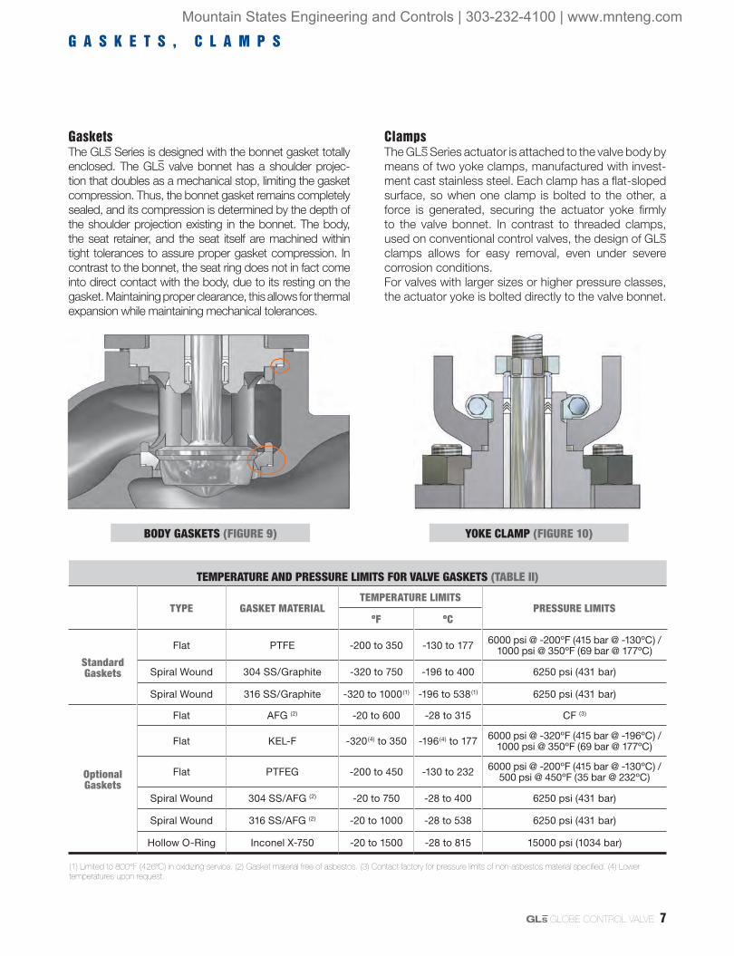
GasketsThe GLS Series is designed with the bonnet gasket totally enclosed. The GLS valve bonnet has a shoulder projec-tion that doubles as a mechanical stop, limiting the gasket compression. Thus, the bonnet gasket remains completely sealed, and its compression is determined by the depth of the shoulder projection existing in the bonnet. The body, the seat retainer, and the seat itself are machined within tight tolerances to assure proper gasket compression. In contrast to the bonnet, the seat ring does not in fact come into direct contact with the body, due to its resting on the gasket. Maintaining proper clearance, this allows for thermal expansion while maintaining mechanical tolerances.
ClampsThe GLS Series actuator is attached to the valve body by means of two yoke clamps, manufactured with invest-ment cast stainless steel. Each clamp has a flat-sloped surface, so when one clamp is bolted to the other, a force is generated, securing the actuator yoke firmly to the valve bonnet. In contrast to threaded clamps, used on conventional control valves, the design of GLS clamps allows for easy removal, even under severe corrosion conditions.For valves with larger sizes or higher pressure classes, the actuator yoke is bolted directly to the valve bonnet.
G A S K E T S , C L A M P S
BODY GASKETS (FIGURE 9) YOKE CLAMP (FIGURE 10)
TEMPERATURE AND PRESSURE LIMITS FOR VALVE GASKETS (TABLE II)
TYPE GASKET MATERIALTEMPERATURE LIMITS
PRESSURE LIMITSºF ºC
Standard Gaskets
Flat PTFE -200 to 350 -130 to 177 6000 psi @ -200ºF (415 bar @ -130ºC) / 1000 psi @ 350ºF (69 bar @ 177ºC)
Spiral Wound 304 SS/Graphite -320 to 750 -196 to 400 6250 psi (431 bar)
Spiral Wound 316 SS/Graphite -320 to 1000(1) -196 to 538(1) 6250 psi (431 bar)
Optional Gaskets
Flat AFG (2) -20 to 600 -28 to 315 CF (3)
Flat KEL-F -320(4) to 350 -196(4) to 177 6000 psi @ -320ºF (415 bar @ -196ºC) / 1000 psi @ 350ºF (69 bar @ 177ºC)
Flat PTFEG -200 to 450 -130 to 232 6000 psi @ -200ºF (415 bar @ -130ºC) / 500 psi @ 450ºF (35 bar @ 232ºC)
Spiral Wound 304 SS/AFG (2) -20 to 750 -28 to 400 6250 psi (431 bar)
Spiral Wound 316 SS/AFG (2) -20 to 1000 -28 to 538 6250 psi (431 bar)
Hollow O-Ring Inconel X-750 -20 to 1500 -28 to 815 15000 psi (1034 bar)
(1) Limited to 800°F (426ºC) in oxidizing service. (2) Gasket material free of asbestos. (3) Contact factory for pressure limits of non-asbestos material specified. (4) Lower temperatures upon request.
Mountain States Engineering and Controls | 303-232-4100 | www.mnteng.com

8 GL S GLOBE CONTROL VALVE
B O N N E T T Y P E S
GLS CONTROL VALVE - BONET TYPES (FIGURE 11)
Cryogenic BonnetThe design of the GL S Series ex-tended bonnet for cryogenic services allows a small portion of the vaporized cryogenic liquid to remain trapped in-side the bonnet, creating a suitable temperature gradient that protects the packing. It is usually made from 304 or 316 stainless steel to withstand low temperatures down to -425ºF (-253ºC). For this type of construction, the standard material of the bonnet flange and bolting is stainless steel.
Standard BonnetThe GLS Series standard bonnet is generally manufac-tured with the same material as the valve body and withstands operating temperatures from -20º to 750ºF (-28º to 400ºC), depending on the packing material (see temperature limits for different packing materials in table IV).
Extended BonnetThe extended bonnet protects the packing against excessive heat or cold that could affect the performance of the valve. Extended bonnets manufactured with carbon steel can be used with operating temperatures from -20º to 800ºF (-28º to 426ºC); extended bonnet manufactured with 304 or 316 stainless steel can work with operating temperatures from -150º to 1500ºF (-100º to 815ºC). Alternative materials are also available.
BONNET FLANGE AND BOLTING SPECIFICATIONS (TABLE III)
BONNET FLANGE (STANDARD)
BONNET FLANGE (OPTIONAL)
BONNET FLANGE STUDS & NUTS (STANDARD)
BONNET FLANGE STUDS & NUTS (OPTIONAL)
Carbon Steel Stainless Steel (1) or same material as body
ASTM A193 Gr. B7 / ASTM A194 Gr. 2H (2)
304 or 316 Stainless Steel (1) (3) (4)
(1) Optional materials of bonnet flange and bonnet flange bolting are always necessary when exceeding the temperature limits of standard carbon steel or B7/2H. (2) Operating tem-perature from -20º to 800ºF (-28º to 426°C), provided that the body limits are respected. (3) Operating temperature from -425º to 1500ºF (-253º to 815°C), provided that the body limits are respected. (4) Other materials upon request, depending on operating conditions and design criteria.
Mountain States Engineering and Controls | 303-232-4100 | www.mnteng.com
GL S GLOBE CONTROL VALVE 9
P A C K I N G , G U I D I N G
TYPICAL PACKING ARRANGEMENT (FIGURE 12)
Upper Guide
Upper Packing Set
Wiper Packing Set
Lower Guide
PACKING TEMPERATURE LIMITS (TABLE IV)
BONNET TYPE PACKING MATERIAL
TEMPERATURE LIMITS(2)
ºF ºC
Standard(1)
PTFE “V” Rings -20 to 450 -28 to 232
PT and PTG -20 to 450 -28 to 232
Braided PTFE -20 to 500 -28 to 260
Glass-filled PTFE (PTFEG) -20 to 500 -28 to 260
PTG XT -20 to 550 -28 to 288
Graphite/AFP(3) -20 to 750 -28 to 400
Graphite/AFP(3), Inconel wire -20 to 750(4) -28 to 400(4)
Graphite(5) -20 to 750(4) -28 to 400(4)
Extended(1)
PTFE “V” Rings -150 to 600 -100 to 316
PT and PTG -20 to 600 -28 to 316
Braided PTFE -150 to 600 -100 to 316
Glass-filled PTFE (PTFEG) -150 to 600 -100 to 316
PTG XT -20 to 700 -28 to 371
Graphite/AFP(3) -20 to 1200 -28 to 650
Graphite/AFP(3), Inconel wire -20 to 1200 -28 to 650
Graphite(5) -20 to 1500 -28 to 815
Cryogenic(1)PTFE, with 15 or 18 in. extension length -320 -196
PTFE, with 24 or 27 in. extension lenght -425 -253
(1) ANSI B16.34 specifies acceptable pressure and temperature limits for pressure retaining materials. Contact manufactu rer for additional information about the pressure vs. temperature limits of packings. (2) Temperature limits are valid provided that the pressure vs. temperature limits of body, bonnet, and remaining parts are respected. (3) High temperature packing, free of asbestos. (4) For sizes from 8 to 12 inches, the maximum temperature limit is 850ºF (454ºC). (5) Do not use graphite packing in oxidizing services such as air or oxygen with operating temperatures higher than 750ºF (400ºC). Due to the increased friction, the use of graphite packing may require the use of extra-strong springs and/or oversized actuators.
TEMPERATURE AND PRESSURE LIMITS FOR PLUG GUIDES/INSERTS (TABLE V)
GUIDE/INSERT MATERIALS
TEMPERATURE LIMITS PRESSURE LIMITSºF ºC
Stainless Steel with Graphite Insert (1) (2)
-320 to 1500(3) -196 to 815(3)
up to 1000 psi (69.0 bar) for sizes up to 2 in.up to 600 psi (41.4 bar) for sizes 3 and 4 in.up to 500 psi (34.5 bar) for sizes 6 in. and larger
Stainless Steel with PTFEG Insert
-20 to 300 -28 to 150850 psi @ 100ºF (58.6 bar @ 38ºC); 100 psi @ 300ºF (6.9 bar @ 150ºC)
Bronze (solid guide) (4) -425 to 500(5) - 253 to 260(5) Body rating
Alloy #6 (solid guide) (6) -425 to 1500 - 253 to 815 Body rating
(1) The ∆P through the valve must be observed for each valve size. Contact factory. (2) Do not use in oxygen en-riched services. In applications under cavitation condition, the use of a lower guide with a graphite insert is not recommended. (3) For oxidizing services such as air, the maximum operating temperature is 800ºF (426ºC). (4) Bronze solid guides should not be used in corrosive applications or where NACE certification is required. (5) For the upper guide, the maximum temperature limit is 900ºF (482ºC). (6) Whenever the valve trim is a 300 series stainless steel and the lower guide is made from Alloy #6, the plug stem must be hardened with Alloy #6 in the stem region in contact with the lower guide.
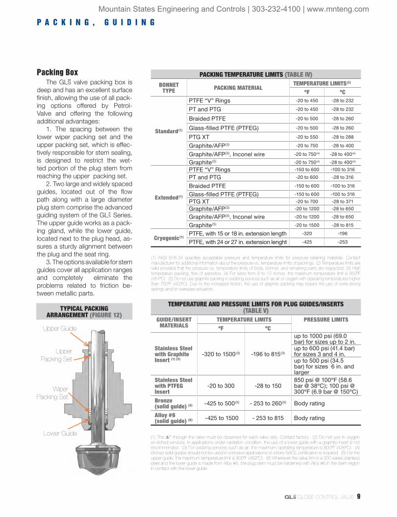
Packing BoxThe GLS valve packing box is
deep and has an excellent surface finish, allowing the use of all pack-ing options offered by Petrol-Valve and offering the following additional advantages:
1. The spacing between the lower wiper packing set and the upper packing set, which is effec-tively responsible for stem sealing, is designed to restrict the wet-ted portion of the plug stem from reaching the upper packing set.
2. Two large and widely spaced guides, located out of the flow path along with a large diameter plug stem comprise the advanced guiding system of the GL S Series. The upper guide works as a pack-ing gland, while the lower guide, located next to the plug head, as-sures a sturdy alignment between the plug and the seat ring.
3. The options available for stem guides cover all application ranges and completely eliminate the problems related to friction be-tween metallic parts.
Mountain States Engineering and Controls | 303-232-4100 | www.mnteng.com
10 GL S GLOBE CONTROL VALVE
F U G I T I V E E M I S S I O N S C O N T R O L
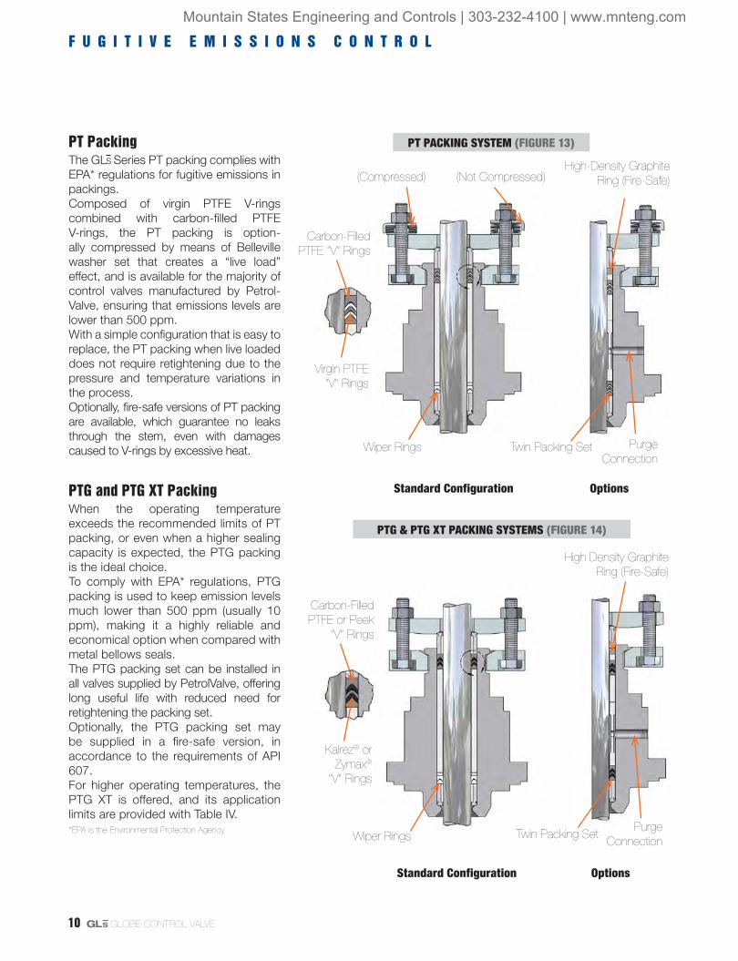
PT PackingThe GL S Series PT packing complies with EPA* regulations for fugitive emissions in packings. Composed of virgin PTFE V-rings combined with carbon-filled PTFE V-rings, the PT packing is option-ally compressed by means of Belleville washer set that creates a “live load” effect, and is available for the majority of control valves manufactured by Petrol-Valve, ensuring that emissions levels are lower than 500 ppm.With a simple configuration that is easy to replace, the PT packing when live loaded does not require retightening due to the pressure and temperature variations in the process.Optionally, fire-safe versions of PT packing are available, which guarantee no leaks through the stem, even with damages caused to V-rings by excessive heat.
PTG and PTG XT PackingWhen the operating temperature exceeds the recommended limits of PT packing, or even when a higher sealing capacity is expected, the PTG packing is the ideal choice.To comply with EPA* regulations, PTG packing is used to keep emission levels much lower than 500 ppm (usually 10 ppm), making it a highly reliable and economical option when compared with metal bellows seals.The PTG packing set can be installed in all valves supplied by PetrolValve, offering long useful life with reduced need for retightening the packing set.Optionally, the PTG packing set may be supplied in a fire-safe version, in accordance to the requirements of API 607.For higher operating temperatures, the PTG XT is offered, and its application limits are provided with Table IV. *EPA is the Environmental Protection Agency
PT PACKING SYSTEM (FIGURE 13)
PTG & PTG XT PACKING SYSTEMS (FIGURE 14)
High-Density Graphite Ring (Fire-Safe)
Purge Connection
Twin Packing Set
(Compressed) (Not Compressed)
Wiper Rings
Virgin PTFE “V” Rings
Carbon-Filled PTFE “V” Rings
Standard Configuration Options
High Density Graphite Ring (Fire-Safe)
Carbon-Filled PTFE or Peek
“V” Rings
Twin Packing SetPurge
Connection
Kalrez® or Zymax®
“V” Rings
Standard Configuration Options
Wiper Rings
Mountain States Engineering and Controls | 303-232-4100 | www.mnteng.com

GL S GLOBE CONTROL VALVE 11
TrimThe GL S Series trim was developed to eliminate issues normally associated with valves with threaded seats or with cage-guided plug designs. Since the seat is not threa ded, but is fixed onto the body by means of the bonnet and the seat retainer, its removal is quite simple, even when the valve operates in corrosive conditions.In contrast to trim with a guide in the seat retainer, which is easily susceptible to wear and jamming, the GLS Series trim is guided by a double upper guide system that avoids contact between the seat retainer and the plug. Since there is no direct contact with the plug, the retainer may be manufactured in materials such as stainless steel, instead of costly hardened materials. The flow characteristic is determined by the plug shape, instead of by openings located in the retainer. For services with very high differential pressures, a pressure-balanced trim design is used to reduce the thrust needed to stroke the plug through the reduction of off-balance trim areas.Valves with pressure-balanced trim should be used with clean fluids only, considering also that flow direction for the safety fail-closed position is under the plug, and for the fail-open position is over the plug.Optionally, the GL S Series may be supplied with special trim to attenuate the noise level and for applications in which cavitation conditions exist.
T R I M T Y P E S , S E A T S
Metal SeatsThe GLS valve standard configuration, with an unbalanced trim and metal seat, complies with ANSI B16.104/FCI 70.2 class IV which specifies a maximum allowable leakage of 0.01% of nominal valve capacity.The exceptional sealing capacity of the GL S Series is easily reached due to its self-centering seat design. Higher seat leakage classes are available as an option.
Soft SeatsSoft seats are used in applications requiring extreme tightness, complying with ANSI B16.104/FCI 70.2 class VI. The GLS soft seat is composed of a polymer assembled between two metal pieces, and it is interchangeable with the metal seat. The soft seat inserts are usually manufactured in PTFE, and therefore the maximum operating tempera-ture should be lower than 300ºF @ 290 psig (150ºC @ 20 barg). Also available in PTFE, Fiber Glass and PEEK. For temperatures below -85ºF (-65ºC), soft seats may be used in high-pressure applications.
SPECIFICATION GUIDE FOR PRESSURE-BALANCED PLUG SEALS (TABLE VI)
MATERIAL OF PLUG SEALS(1) TEMPERATURE LIMITS(2) SHUTOFF CLASSºF ºC WITH METAL SEAT WITH SOFT SEAT
PTFE Seals 0 to 350 -18 to 176 up to 10% of Class IV up to 1% of Class IVReinforced PTFE Seals 0 to 400 -18 to 204 up to 10% of Class IV up to 1% of Class IVBuna-N O-Ring -40 to 200 -40 to 93 Class IV or V Class VIViton-A O-Ring -10 to 400 -23 to 204 Class IV or V Class VIVMG Metal Seals Sizes from 2 to 4 in. 300 to 1600 149 to 871 Class III N/A Sizes 6 in. and larger 300 to 1600 149 to 871 Class IV N/A
(1) Whenever metal seals are used, such as VMGs, the bore surface of the pressure-balanced sleeve must be hardened. (2) The temperature limits above are for information purposes only. Contact PetrolValve to confirm the maximum allowable temperature regarding the operating pressure.
UNBALANCED TRIM (FIGURE 15)
PRESSURE-BALANCED TRIM (FIGURE 16)
Mountain States Engineering and Controls | 303-232-4100 | www.mnteng.com

12 GL S GLOBE CONTROL VALVE
T R I M D A T A , S E A T S
Trim Data
Seats
Insert RetainerSoftInsert
Soft Seat Ring
Soft Seat Configuration
Seat Surface
Full Bore
GLS SERIES - SEAT OPTIONS (FIGURE 17)
STANDARD UNBALANCED TRIM AND ACTUATOR DATA (TABLE VII)
VALVE SIZE
(Inches)ANSI
CLASS
FULL AREA
TRIM SIZESEAT AREA
STEM DIAMETER
STEM AREA STROKE
STANDARD ACTUATOR
SIZE
in. mm in.2 cm2 in. mm in.2 cm2 in. mm0.5 150-600 0.50 13 0.196 1.267 0.575 14.6 0.259 1.674 0.75 19.05 25
0.75 150-600 0.71 18 0.405 2.612 0.575 14.6 0.259 1.674 0.75 19.05 25
1 150-600 0.81 21 0.518 3.345 0.575 14.6 0.259 1.674 0.75 19.05 25
1.5 150-600 1.25 32 1.227 7.917 0.890 22.6 0.622 4.011 1.00 25.40 25
2 150-600 1.63 41 2.074 13.38 0.890 22.6 0.622 4.011 1.50 38.10 25
3 150-600 2.63 67 5.412 34.92 1.138 28.9 1.017 6.560 2.00 50.80 50
4 150-600 3.50 89 9.621 62.07 1.138 28.9 1.017 6.560 2.50 63.50 50
6150 5.00 127 19.63 126.7 1.138 28.9 1.017 6.560 3.00 76.20 50
300-600 5.00 127 19.63 126.7 2.024 51.4 3.216 20.75 3.00 76.20 100
8150 6.25 159 30.68 198.0 1.520 38.6 1.814 11.70 4.00 101.6 100
300-600 6.25 159 30.68 198.0 2.024 51.4 3.216 20.75 4.00 101.6 100
10150 8.00 203 50.27 324.3 2.024 51.4 3.216 20.75 4.00 101.6 100
300-600 8.00 203 50.27 324.3 2.524 64.1 5.002 32.27 4.00 101.6 100
12150 9.50 241 70.88 457.3 2.024 51.4 3.216 20.75 4.00 101.6 100
300-600 9.50 241 70.88 457.3 3.024 76.8 7.180 46.32 4.00 101.6 100
PRESSURE-BALANCED TRIM AND ACTUATOR DATA (TABLE VIII)
VALVE SIZE
(Inches)ANSI
CLASS
FULL AREA TRIM SIZE
SEAT AREA
STEM DIAMETER
STEM AREA
SLEEVE AREA
OFF-BALANCE AREA
STROKESTANDARD ACTUATOR
SIZETENDING TO CLOSE
(Flow Under)
TENDING TO OPEN
(Flow Over)
in. mm in.2 cm2 in. mm in.2 cm2 in.2 cm2 in.2 cm2 in.2 cm2 in. mm2 150-600 1.63 41 2.074 13.38 0.575 14.6 0.259 1.674 2.58 16.65 0.25 1.60 0.51 3.28 1.00 25.4 25
3 150-600 2.63 67 5.412 34.92 0.890 22.6 0.622 4.011 6.77 43.68 0.74 4.75 1.36 8.78 1.50 38.1 50
4 150-600 3.50 89 9.621 62.07 0.890 22.6 0.622 4.011 11.41 73.61 1.17 7.53 1.79 11.6 2.00 50.8 50
6150 5.00 127 19.63 126.7 1.138 28.9 1.017 6.560 22.69 146.4 2.04 13.1 3.06 19.7 2.50 63.5 50
300-600 5.00 127 19.63 126.7 1.520 38.6 1.814 11.70 23.76 153.3 2.32 14.9 4.13 26.6 2.50 63.5 100
8 150-600 6.25 159 30.68 198.0 1.520 38.6 1.814 11.70 35.78 230.8 3.29 21.1 5.10 32.9 3.00 76.2 100
10 150-600 8.00 203 50.27 324.3 2.024 51.4 3.216 20.75 58.36 376.5 4.87 31.5 8.09 52.2 3.00 76.2 100
12 150-600 9.50 241 70.88 457.3 2.524 64.1 5.002 32.27 82.52 532.4 6.64 42.8 11.6 75.1 4.00 102 100
Mountain States Engineering and Controls | 303-232-4100 | www.mnteng.com

GL S GLOBE CONTROL VALVE 13
T R I M , M A T E R I A L S
The standard manufactur-ing material for the GLS plug, seat and seat retainer is 316 stainless steel, except in cases where special alloys are required or specifed. As a general rule, hardened trim, such as Alloy #6 facing, shall be used for all conditions of critical flow or in services where the operat-ing temperature exceeds 600ºF (316ºC). Special alloys such as Alloy 20, Monel, Hastel-loy C, Hastelloy B, and other materials, may be supplied upon request.
PLUG - HARD FACING VARIATIONS(FIGURE 18)
DIFFERENTIAL PRESSURE VALUES REQUIRING HARDENED TRIM (TABLE IX)
VALVE SIZE
(Inches)
WATER STEAM (SATURATED) STEAM (SUPER-HEATED)
PROCESS FLUIDS (GENERAL) CLEAN GASES
Throttling On-Off Throttling On-Off Throttling On-Off Throttling On-Off Throttling On-Off
psi Bar psi Bar psi Bar psi Bar psi Bar psi Bar psi Bar psi Bar psi Bar psi Bar
0.5 to 1.5 175 12.1 250 17.2 100 6.9 200 13.8 300 20.7 600 41.4 175 12.1 250 17.2 600 41.4 900 62.1
2 & 3 150 10.3 200 13.8 25 1.7 50 3.4 200 13.8 300 20.7 150 10.3 200 13.8 350 24.1 600 41.4
4 & 6 100 6.9 125 8.6 All Apps. 25 1.7 100 6.9 150 10.3 75 5.2 125 8.6 200 13.8 300 20.7
8 to 12 50 3.4 100 6.9 All Apps. All Apps. 50 3.4 100 6.9 50 3.4 100 6.9 125 8.6 175 12.1
CHARACTERISTICS OF TRIM MATERIALS (TABLE X)
TRIM MATERIALS HARDNESS (RC)
MAX. RECOMMENDED TEMPERATURE IMPACT
STRENGTHCORROSION RESISTANCE
EROSION RESISTANCE
ABRASION RESISTANCE
ºF ºC316 Stainless Steel 8 600 316 Excellent Excellent Fair Fair
Alloy #6 44 1500 815 Excellent Excellent Good Good
416 Stainless Steel 40 800 426 Good Fair Good Good
17-4 PH (H900) 44 800 426 Good Good to Excellent Good Good440C Stainless
Steel 55-60 800 426 Fair Fair Excellent Excellent
Monel K-500 32 600 316 Good Good to Excellent Fair to Good Good
Tungsten 72 1200 650 Fair Good on Bases, Poor on Acids Excellent Excellent
Colmonoy #5 45-50 1200 650 Good Fair Good Good
Seat Surface
Lower Guide Area
Full Contour
Full Contour & LGA
Mountain States Engineering and Controls | 303-232-4100 | www.mnteng.com

14 GL S GLOBE CONTROL VALVE
G L S O V E R V I E W
*PTFEG: Glass-Filled PTFE. **AFP: Asbestos-free packing.
GLS SERIES - SPECIFICATIONS & MATERIALS OF CONSTRUCTION (TABLE XI)
BODY
Sizes 0.5 to 48 inches
ANSI Ratings 150, 300, and 600
Forms Globe, angle, 3-Way, or steam jacketed versions
Materials of ConstructionCarbon steel, Stainless steel, Chrome-Moly steel, Alloy 20, Bronze, Monel, Hastelloy B, Hastelloy C, Nickel, Titanium and other castable alloys upon request
End Connections
Separable flanges (0.5 to 4 inches)Integral flanges (all sizes)NPT threaded (0.5 to 2 inches)Socketweld (0.5 to 4 inches) Buttweld (all sizes)Grayloc (all sizes)
Separable Flanges Carbon steel, 316 stainless steel, or other materials upon request
Gaskets
Flat PTFE, PTFEG*, KEL-F
Spiral Wound 316 or 304 SS spiral wound with graphite, PTFE, or other filler materials free of asbestos (AFG)
O-Rings Inconel X-750 / silver plated hollow O-Ring
BONNET
Types Standard, extended, criogenic with special length extension
Materials Same as body
Bonnet Flange Separable, made from carbon steel or 316 stainless steel
GuidesType Double upper guide on plug stem, out of flow path
Materials 316 SS with PTFEG* or graphite insert, bronze, Alloy #6 or other materials available upon request
PackingsTypes Standard with “V” or square rings, twin seal, packing for vacuum
applications
Materials PTFE V-rings, PTFEG* V-rings, braided PTFE, AFP** with Inconel wire, graphite and other materials upon request
TRIM
Types UnbalancedPressure-balanced, with elastomer, polymer or metal plug seals
Flow Characteristics Equal Percentage, Linear, or Quick-Open
Materials316 SS (standard), 304 SS, 347 SS, 416 SS, 420 SS, 440C SS, Alloy 20, Monel, Hastelloy B, Hastelloy C, 17-4 PH, Nickel, Titanium, Tungsten Carbide and others
Hard Facings
Materials Alloy #6, Colmonoy #5, Tungsten Carbide, Boronization, and others
TypesHardening of seating surfaces, hardening of plug full contour and seat full bore, hardening of plug stem region in contact with the lower guide
Soft Seats Materials PTFE, PTFEG*, FEP, KEL-F, Polyurethane, PEEK
ACTUATOR TypesPneumatic
Double-acting cylinder with positive spring for fail-safe action. Field-reversible and available on sizes 25, 50, 100, 200, 300, 400, 500, and 600. Options: manual handwheel, limit stops, and others (see the technical bulletin of linear actuators).
Others Manual, electro-mechanical or electro-hydraulic upon request
POSITIONER Types Pneumatic, analog electro-pneumatic or digital electro-pneumatic with multiple communication protocols
Mountain States Engineering and Controls | 303-232-4100 | www.mnteng.com

GL S GLOBE CONTROL VALVE 15
F L O W C H A R A C T E R I S T I C S
Equal PercentageEqual Percentage is the most common characteristic used in process control. The flow rate change by valve stroke unit is directly proportional to the flow rate passing through the valve at the moment immediately before the stroke movement. Whenever the total differential pressure of the system is large when compared to the differential pressure through the valve, a valve with an Equal Percentage characteristic will perform in most control loops, similarly to a valve with a Linear characteristic.
LinearThe Linear characteristic creates equal chan-ges in flow rate per unit of valve stroke, regardless of plug position. Linear plugs are frequently used in systems where the differen-tial pressure through the valve corresponds to the major part of the total differential pressure of the system.
Quick-openQuick-open plugs are used in on-off services and are designed to create large increments of flow rate, even from small opening percentages.
Trim SizesTwo sizes of trim are normally available: the standard size, with full-area trim; and the second size, with reduced area trim. Reduced area trims are available in a wide variety of dimensions, which are necessary when the required CV, due to the process conditions, is relatively small for a specific body size intended to be used. In addition to these options, an integral trim may be supplied, which uses a special seat machined onto the valve body and an oversized plug to provide an even larger CV than the CV provided by the standard full-area trim.As the GLS valve trim is completely interchangeable for a specific body size and pressure class, the change of trim size and valve nominal CV is a very simple operation.
TRIM SIZES (FIGURE 19)
Full Area Reduced Area Integral
% F
low
% F
low
% F
low
% Valve Stroke (Equal Percentage)
% Valve Stroke (Linear)
% Valve Stroke (Quick-Open)
100
50
0 50 100
0 50 100
0 50 100
100
50
100
50
Mountain States Engineering and Controls | 303-232-4100 | www.mnteng.com

16 GL S GLOBE CONTROL VALVE
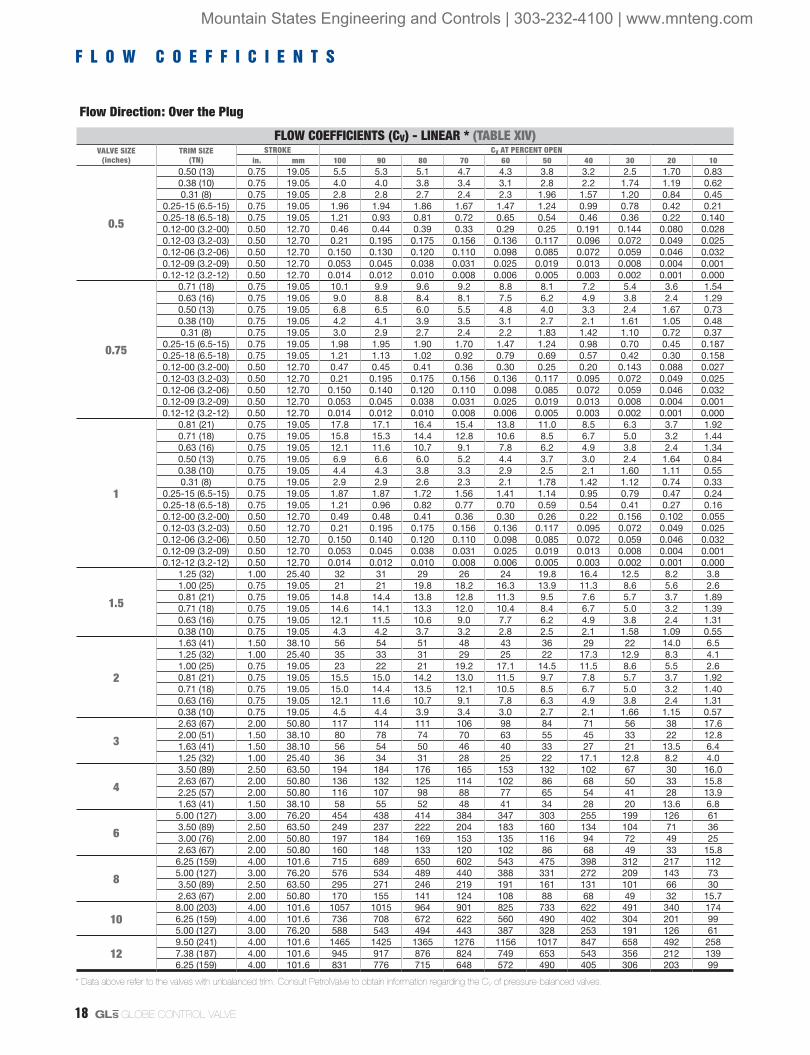
F L O W C O E F F I C I E N T S
Flow Direction: Over the Plug
FLOW COEFFICIENTS (CV) - EQUAL PERCENTAGE * (TABLE XII)VALVE SIZE
(inches)TRIM SIZE
(TN)STROKE CV AT PERCENT OPEN
in. mm 100 90 80 70 60 50 40 30 20 10
0.5
0.50 (13) 0.75 19.05 5.0 4.6 3.7 2.6 1.86 1.36 0.90 0.55 0.33 0.25
0.38 (10) 0.75 19.05 3.7 3.3 2.5 1.63 1.23 0.85 0.49 0.31 0.189 0.127
0.31 (8) 0.75 19.05 2.8 2.5 1.76 1.22 0.94 0.58 0.33 0.22 0.149 0.095
0.25-03 (6.5-03) 0.75 19.05 1.94 1.60 1.08 0.81 0.56 0.37 0.23 0.142 0.090 0.060
0.25-06 (6.5-06) 0.75 19.05 1.25 1.03 0.70 0.52 0.36 0.24 0.147 0.092 0.058 0.038
0.12-00 (3.2-00) 0.50 12.70 0.46 0.45 0.38 0.27 0.168 0.103 0.072 0.043 0.026 0.015
0.75
0.71 (18) 0.75 19.05 9.5 9.0 7.6 5.6 3.9 3.2 2.3 1.61 1.00 0.63
0.63 (16) 0.75 19.05 9.0 8.3 6.6 4.6 3.0 2.3 1.57 0.94 0.59 0.32
0.50 (13) 0.75 19.05 6.5 5.9 4.7 3.0 2.0 1.54 0.98 0.63 0.37 0.24
0.38 (10) 0.75 19.05 4.2 3.7 2.9 1.75 1.38 0.87 0.46 0.29 0.165 0.106
0.31 (8) 0.75 19.05 2.9 2.6 1.65 1.23 0.88 0.59 0.31 0.20 0.151 0.093
0.25-03 (6.5-03) 0.75 19.05 1.98 1.83 1.22 0.91 0.57 0.35 0.21 0.140 0.087 0.059
0.25-06 (6.5-06) 0.75 19.05 1.28 1.26 0.96 0.63 0.37 0.23 0.131 0.087 0.051 0.024
0.12-00 (3.2-00) 0.50 12.70 0.47 0.47 0.37 0.24 0.151 0.088 0.056 0.036 0.018 0.006
1
0.81 (21) 0.75 19.05 15.6 14.2 11.3 8.1 4.9 3.3 2.8 2.1 1.61 1.07
0.71 (18) 0.75 19.05 13.5 11.8 8.9 6.1 3.9 3.1 2.3 1.65 1.12 0.70
0.63 (16) 0.75 19.05 10.3 8.7 6.5 4.2 2.7 2.3 1.53 0.98 0.61 0.35
0.50 (13) 0.75 19.05 6.6 5.8 4.5 2.9 2.0 1.55 1.10 0.73 0.47 0.26
0.38 (10) 0.75 19.05 4.1 3.4 2.3 1.54 1.31 0.85 0.51 0.33 0.22 0.140
0.31 (8) 0.75 19.05 2.9 2.4 1.64 1.16 0.93 0.61 0.35 0.20 0.138 0.089
0.25-03 (6.5-03) 0.75 19.05 1.87 1.53 1.08 0.82 0.55 0.31 0.21 0.132 0.082 0.055
0.25-06 (6.5-06) 0.75 19.05 1.26 1.24 0.94 0.63 0.37 0.23 0.129 0.085 0.051 0.024
0.12-00 (3.2-00) 0.50 12.70 0.47 0.46 0.29 0.22 0.158 0.113 0.085 0.063 0.043 0.026
1.5
1.25 (32) 1.00 25.40 28 26 21 15.6 10.3 6.7 5.0 3.6 2.3 1.57
1.00 (25) 0.75 19.05 19.1 17.3 14.5 10.9 7.2 4.5 3.3 2.4 1.57 1.06
0.81 (21) 0.75 19.05 12.8 11.3 8.9 6.3 4.0 2.6 1.76 1.05 0.69 0.33
0.63 (16) 0.75 19.05 7.8 6.7 5.2 3.7 2.5 1.7 1.15 0.64 0.40 0.22
0.38 (10) 0.75 19.05 3.6 2.8 1.94 1.42 1.24 0.87 0.58 0.30 0.182 0.109
2
1.63 (41) 1.50 38.10 46 41 34 25 16.3 11.4 9.1 5.9 3.8 2.6
1.25 (32) 1.00 25.40 31 27 22 16.0 10.3 6.6 5.2 3.6 2.3 1.56
1.00 (25) 0.75 19.05 21 18.5 15.3 11.2 7.5 4.7 3.3 2.5 1.58 1.06
0.81 (21) 0.75 19.05 13.7 12.2 9.8 7.0 4.4 2.8 2.2 1.45 0.94 0.64
0.63 (16) 0.75 19.05 9.0 8.0 6.2 4.2 2.6 2.0 1.44 0.89 0.53 0.31
0.38 (10) 0.75 19.05 3.6 3.3 2.6 1.76 1.17 0.93 0.56 0.35 0.22 0.152
3
2.63 (67) 2.00 50.80 105 96 86 77 61 38 22 16.4 10.3 5.9
2.00 (51) 1.50 38.10 79 74 67 56 41 24 13.5 8.9 6.4 3.7
1.63 (41) 1.50 38.10 51 45 35 24 15.5 10.3 8.2 5.6 3.5 2.5
1.25 (32) 1.00 25.40 32 28 23 15.8 10.5 6.8 5.1 3.5 2.3 1.48
4
3.50 (89) 2.50 63.50 180 170 155 131 97 57 35 26 20 13.0
2.63 (67) 2.00 50.80 133 124 111 89 63 39 24 16.3 11.4 7.4
2.25 (57) 2.00 50.80 103 95 82 62 40 24 14.9 11.6 7.3 4.6
1.63 (41) 1.50 38.10 56 49 38 25 16.3 10.7 8.6 5.8 3.7 2.5
6
5.00 (127) 3.00 76.20 356 334 303 265 203 125 59 33 20 13.9
3.50 (89) 2.50 63.50 231 216 193 153 102 58 35 23 17.5 11.1
3.00 (76) 2.00 50.80 191 153 120 101 61 38 26 16.9 11.9 7.9
2.63 (67) 2.00 50.80 139 131 117 94 64 37 22 16.3 10.9 6.8
8
6.25 (159) 4.00 101.6 608 566 501 414 306 182 107 73 55 34
5.00 (127) 3.00 76.20 462 429 370 291 202 125 59 33 20 14.0
3.50 (89) 2.50 63.50 248 231 203 160 109 61 34 21 13.0 6.9
2.63 (67) 2.00 50.80 142 133 117 94 64 36 22 15.8 10.8 6.9
10
8.00 (203) 4.00 101.6 900 846 765 658 527 372 193 99 60 42
6.25 (159) 4.00 101.6 687 632 546 423 304 180 107 73 49 34
5.00 (127) 3.00 76.20 491 451 382 288 200 124 59 33 19.8 13.9
12
9.50 (241) 4.00 101.6 1306 1211 1077 917 695 427 229 153 108 73
7.38 (187) 4.00 101.6 962 886 752 586 422 251 149 101 68 46
6.25 (159) 4.00 101.6 771 713 590 441 305 181 107 73 49 34
* Data above refer to the valves with unbalanced trim. Consult PetrolValve to obtain information regarding the CV of pressure-balanced valves.
Mountain States Engineering and Controls | 303-232-4100 | www.mnteng.com

GL S GLOBE CONTROL VALVE 17
Flow Direction: Under the Plug
FLOW COEFFICIENTS (CV) - EQUAL PERCENTAGE * (TABLE XIII)VALVE SIZE
(inches)TRIM SIZE
(TN)STROKE CV AT PERCENT OPEN
in. mm 100 90 80 70 60 50 40 30 20 10
0.5
0.50 (13) 0.75 19.05 4.9 4.7 3.9 2.3 1.64 1.07 0.72 0.45 0.30 0.20
0.38 (10) 0.75 19.05 3.5 3.1 2.3 1.52 1.01 0.69 0.41 0.27 0.180 0.131
0.31 (8) 0.75 19.05 2.5 2.2 1.64 1.07 0.70 0.46 0.28 0.21 0.148 0.106
0.25-03 (6.5-03) 0.75 19.05 1.76 1.55 1.02 0.66 0.43 0.27 0.176 0.108 0.074 0.048
0.25-06 (6.5-06) 0.75 19.05 1.18 1.16 0.81 0.50 0.33 0.20 0.134 0.092 0.068 0.059
0.12-00 (3.2-00) 0.50 12.70 0.44 0.43 0.41 0.25 0.160 0.100 0.067 0.044 0.029 0.017
0.75
0.71 (18) 0.75 19.05 9.5 8.9 7.5 5.5 3.2 2.2 1.38 0.94 0.67 0.43
0.63 (16) 0.75 19.05 8.5 8.4 6.3 4.3 2.8 1.78 1.23 0.75 0.45 0.27
0.50 (13) 0.75 19.05 6.1 5.8 4.7 2.9 1.87 1.20 0.77 0.47 0.30 0.183
0.38 (10) 0.75 19.05 3.7 3.4 2.7 1.72 1.10 0.70 0.42 0.27 0.160 0.096
0.31 (8) 0.75 19.05 2.7 2.4 1.64 1.10 0.70 0.45 0.26 0.181 0.126 0.081
0.25-03 (6.5-03) 0.75 19.05 1.88 1.80 1.27 0.83 0.47 0.31 0.193 0.124 0.079 0.051
0.25-06 (6.5-06) 0.75 19.05 1.18 1.17 0.76 0.50 0.32 0.184 0.112 0.064 0.035 0.013
0.12-00 (3.2-00) 0.50 12.70 0.46 0.46 0.45 0.27 0.159 0.092 0.057 0.034 0.015 0.004
1
0.81 (21) 0.75 19.05 13.5 12.3 9.3 6.6 4.1 2.8 1.87 1.29 0.95 0.66
0.71 (18) 0.75 19.05 12.3 11.4 8.0 5.6 3.5 2.3 1.55 1.04 0.69 0.46
0.63 (16) 0.75 19.05 9.8 9.1 6.1 3.9 2.5 1.69 1.11 0.70 0.45 0.29
0.50 (13) 0.75 19.05 6.6 5.9 4.5 2.7 1.80 1.19 0.78 0.47 0.29 0.195
0.38 (10) 0.75 19.05 3.9 3.4 2.3 1.49 0.98 0.65 0.43 0.29 0.193 0.129
0.31 (8) 0.75 19.05 2.8 2.4 1.63 1.08 0.72 0.48 0.26 0.179 0.125 0.080
0.25-03 (6.5-03) 0.75 19.05 1.80 1.58 1.13 0.70 0.46 0.29 0.186 0.137 0.082 0.058
0.25-06 (6.5-06) 0.75 19.05 1.18 1.04 0.73 0.46 0.31 0.177 0.116 0.083 0.048 0.032
0.12-00 (3.2-00) 0.50 12.70 0.51 0.50 0.33 0.194 0.126 0.085 0.061 0.040 0.025 0.014
1.5
1.25 (32) 1.00 25.40 31 29 25 16.3 11.0 7.0 4.5 3.0 1.91 1.30
1.00 (25) 0.75 19.05 22 22 16.7 10.9 6.6 4.5 3.0 1.90 1.32 0.91
0.81 (21) 0.75 19.05 15.8 13.7 9.4 6.1 4.5 2.6 1.58 0.93 0.59 0.33
0.63 (16) 0.75 19.05 10.0 8.2 6.3 5.3 3.2 1.91 1.08 0.77 0.43 0.27
0.38 (10) 0.75 19.05 3.7 3.2 1.95 1.31 0.88 0.60 0.36 0.23 0.142 0.088
2
1.63 (41) 1.50 38.10 47 45 41 30 16.4 10.6 7.0 4.6 3.1 2.2
1.25 (32) 1.00 25.40 30 29 24 15.6 10.1 6.4 4.3 2.8 1.86 1.25
1.00 (25) 0.75 19.05 23 22 17.7 11.4 6.7 4.6 3.0 1.89 1.27 0.88
0.81 (21) 0.75 19.05 17.5 17.1 12.5 7.9 5.1 3.3 2.1 1.35 0.93 0.61
0.63 (16) 0.75 19.05 10.1 9.1 6.7 4.5 2.7 1.80 1.16 0.74 0.44 0.28
0.38 (10) 0.75 19.05 3.1 2.9 2.6 1.95 1.24 0.81 0.50 0.33 0.21 0.147
3
2.63 (67) 2.00 50.80 109 102 93 89 72 36 21 12.9 7.9 4.5
2.00 (51) 1.50 38.10 83 78 72 64 44 25 13.8 8.8 5.3 3.3
1.63 (41) 1.50 38.10 48 46 41 27 17.0 11.2 7.2 4.7 3.1 2.2
1.25 (32) 1.00 25.40 32 31 25 16.3 10.6 7.0 4.5 2.9 1.90 1.29
4
3.50 (89) 2.50 63.50 196 184 169 157 115 57 36 24 15.4 10.7
2.63 (67) 2.00 50.80 132 122 110 99 66 42 27 17.2 10.3 6.7
2.25 (57) 2.00 50.80 97 89 80 66 41 26 16.3 10.3 6.2 4.2
1.63 (41) 1.50 38.10 57 53 43 28 17.6 11.5 7.5 4.9 3.2 2.2
6
5.00 (127) 3.00 76.20 401 375 340 298 250 148 62 35 18.3 13.7
3.50 (89) 2.50 63.50 225 203 177 153 115 65 41 26 16.5 10.8
3.00 (76) 2.00 50.80 169 152 133 114 73 37 25 16.9 10.9 7.8
2.63 (67) 2.00 50.80 129 118 105 92 67 37 23 14.8 8.8 5.5
8
6.25 (159) 4.00 101.6 693 645 591 498 335 185 115 76 46 28
5.00 (127) 3.00 76.20 458 413 360 299 212 134 65 36 19.0 14.0
3.50 (89) 2.50 63.50 244 219 195 160 114 65 41 26 15.9 11.0
2.63 (67) 2.00 50.80 141 130 115 99 67 36 23 14.8 8.6 5.9
10
8.00 (203) 4.00 101.6 1015 923 819 724 604 425 191 112 70 41
6.25 (159) 4.00 101.6 691 623 543 469 343 189 118 78 47 29
5.00 (127) 3.00 76.20 479 431 376 296 211 133 65 36 18.9 13.9
12
9.50 (241) 4.00 101.6 1407 1287 1138 958 764 533 268 158 99 58
7.38 (187) 4.00 101.6 937 860 758 638 481 268 142 97 65 44
6.25 (159) 4.00 101.6 752 685 614 509 335 185 115 76 46 28
* Data above refer to the valves with unbalanced trim. Consult PetrolValve to obtain information regarding the CV of pressure-balanced valves.
Mountain States Engineering and Controls | 303-232-4100 | www.mnteng.com
18 GL S GLOBE CONTROL VALVE
F L O W C O E F F I C I E N T S
Flow Direction: Over the Plug
FLOW COEFFICIENTS (CV) - LINEAR * (TABLE XIV)VALVE SIZE
(inches)TRIM SIZE
(TN)STROKE CV AT PERCENT OPEN
in. mm 100 90 80 70 60 50 40 30 20 10
0.5
0.50 (13) 0.75 19.05 5.5 5.3 5.1 4.7 4.3 3.8 3.2 2.5 1.70 0.830.38 (10) 0.75 19.05 4.0 4.0 3.8 3.4 3.1 2.8 2.2 1.74 1.19 0.620.31 (8) 0.75 19.05 2.8 2.8 2.7 2.4 2.3 1.96 1.57 1.20 0.84 0.45
0.25-15 (6.5-15) 0.75 19.05 1.96 1.94 1.86 1.67 1.47 1.24 0.99 0.78 0.42 0.210.25-18 (6.5-18) 0.75 19.05 1.21 0.93 0.81 0.72 0.65 0.54 0.46 0.36 0.22 0.1400.12-00 (3.2-00) 0.50 12.70 0.46 0.44 0.39 0.33 0.29 0.25 0.191 0.144 0.080 0.0280.12-03 (3.2-03) 0.50 12.70 0.21 0.195 0.175 0.156 0.136 0.117 0.096 0.072 0.049 0.0250.12-06 (3.2-06) 0.50 12.70 0.150 0.130 0.120 0.110 0.098 0.085 0.072 0.059 0.046 0.0320.12-09 (3.2-09) 0.50 12.70 0.053 0.045 0.038 0.031 0.025 0.019 0.013 0.008 0.004 0.0010.12-12 (3.2-12) 0.50 12.70 0.014 0.012 0.010 0.008 0.006 0.005 0.003 0.002 0.001 0.000
0.75
0.71 (18) 0.75 19.05 10.1 9.9 9.6 9.2 8.8 8.1 7.2 5.4 3.6 1.540.63 (16) 0.75 19.05 9.0 8.8 8.4 8.1 7.5 6.2 4.9 3.8 2.4 1.290.50 (13) 0.75 19.05 6.8 6.5 6.0 5.5 4.8 4.0 3.3 2.4 1.67 0.730.38 (10) 0.75 19.05 4.2 4.1 3.9 3.5 3.1 2.7 2.1 1.61 1.05 0.480.31 (8) 0.75 19.05 3.0 2.9 2.7 2.4 2.2 1.83 1.42 1.10 0.72 0.37
0.25-15 (6.5-15) 0.75 19.05 1.98 1.95 1.90 1.70 1.47 1.24 0.98 0.70 0.45 0.1870.25-18 (6.5-18) 0.75 19.05 1.21 1.13 1.02 0.92 0.79 0.69 0.57 0.42 0.30 0.1580.12-00 (3.2-00) 0.50 12.70 0.47 0.45 0.41 0.36 0.30 0.25 0.20 0.143 0.088 0.0270.12-03 (3.2-03) 0.50 12.70 0.21 0.195 0.175 0.156 0.136 0.117 0.095 0.072 0.049 0.0250.12-06 (3.2-06) 0.50 12.70 0.150 0.140 0.120 0.110 0.098 0.085 0.072 0.059 0.046 0.0320.12-09 (3.2-09) 0.50 12.70 0.053 0.045 0.038 0.031 0.025 0.019 0.013 0.008 0.004 0.0010.12-12 (3.2-12) 0.50 12.70 0.014 0.012 0.010 0.008 0.006 0.005 0.003 0.002 0.001 0.000
1
0.81 (21) 0.75 19.05 17.8 17.1 16.4 15.4 13.8 11.0 8.5 6.3 3.7 1.920.71 (18) 0.75 19.05 15.8 15.3 14.4 12.8 10.6 8.5 6.7 5.0 3.2 1.440.63 (16) 0.75 19.05 12.1 11.6 10.7 9.1 7.8 6.2 4.9 3.8 2.4 1.340.50 (13) 0.75 19.05 6.9 6.6 6.0 5.2 4.4 3.7 3.0 2.4 1.64 0.840.38 (10) 0.75 19.05 4.4 4.3 3.8 3.3 2.9 2.5 2.1 1.60 1.11 0.550.31 (8) 0.75 19.05 2.9 2.9 2.6 2.3 2.1 1.78 1.42 1.12 0.74 0.33
0.25-15 (6.5-15) 0.75 19.05 1.87 1.87 1.72 1.56 1.41 1.14 0.95 0.79 0.47 0.240.25-18 (6.5-18) 0.75 19.05 1.21 0.96 0.82 0.77 0.70 0.59 0.54 0.41 0.27 0.160.12-00 (3.2-00) 0.50 12.70 0.49 0.48 0.41 0.36 0.30 0.26 0.22 0.156 0.102 0.0550.12-03 (3.2-03) 0.50 12.70 0.21 0.195 0.175 0.156 0.136 0.117 0.095 0.072 0.049 0.0250.12-06 (3.2-06) 0.50 12.70 0.150 0.140 0.120 0.110 0.098 0.085 0.072 0.059 0.046 0.0320.12-09 (3.2-09) 0.50 12.70 0.053 0.045 0.038 0.031 0.025 0.019 0.013 0.008 0.004 0.0010.12-12 (3.2-12) 0.50 12.70 0.014 0.012 0.010 0.008 0.006 0.005 0.003 0.002 0.001 0.000
1.5
1.25 (32) 1.00 25.40 32 31 29 26 24 19.8 16.4 12.5 8.2 3.81.00 (25) 0.75 19.05 21 21 19.8 18.2 16.3 13.9 11.3 8.6 5.6 2.60.81 (21) 0.75 19.05 14.8 14.4 13.8 12.8 11.3 9.5 7.6 5.7 3.7 1.890.71 (18) 0.75 19.05 14.6 14.1 13.3 12.0 10.4 8.4 6.7 5.0 3.2 1.390.63 (16) 0.75 19.05 12.1 11.5 10.6 9.0 7.7 6.2 4.9 3.8 2.4 1.310.38 (10) 0.75 19.05 4.3 4.2 3.7 3.2 2.8 2.5 2.1 1.58 1.09 0.55
2
1.63 (41) 1.50 38.10 56 54 51 48 43 36 29 22 14.0 6.51.25 (32) 1.00 25.40 35 33 31 29 25 22 17.3 12.9 8.3 4.11.00 (25) 0.75 19.05 23 22 21 19.2 17.1 14.5 11.5 8.6 5.5 2.60.81 (21) 0.75 19.05 15.5 15.0 14.2 13.0 11.5 9.7 7.8 5.7 3.7 1.920.71 (18) 0.75 19.05 15.0 14.4 13.5 12.1 10.5 8.5 6.7 5.0 3.2 1.400.63 (16) 0.75 19.05 12.1 11.6 10.7 9.1 7.8 6.3 4.9 3.8 2.4 1.310.38 (10) 0.75 19.05 4.5 4.4 3.9 3.4 3.0 2.7 2.1 1.66 1.15 0.57
3
2.63 (67) 2.00 50.80 117 114 111 106 98 84 71 56 38 17.62.00 (51) 1.50 38.10 80 78 74 70 63 55 45 33 22 12.81.63 (41) 1.50 38.10 56 54 50 46 40 33 27 21 13.5 6.41.25 (32) 1.00 25.40 36 34 31 28 25 22 17.1 12.8 8.2 4.0
4
3.50 (89) 2.50 63.50 194 184 176 165 153 132 102 67 30 16.02.63 (67) 2.00 50.80 136 132 125 114 102 86 68 50 33 15.82.25 (57) 2.00 50.80 116 107 98 88 77 65 54 41 28 13.91.63 (41) 1.50 38.10 58 55 52 48 41 34 28 20 13.6 6.8
6
5.00 (127) 3.00 76.20 454 438 414 384 347 303 255 199 126 613.50 (89) 2.50 63.50 249 237 222 204 183 160 134 104 71 363.00 (76) 2.00 50.80 197 184 169 153 135 116 94 72 49 252.63 (67) 2.00 50.80 160 148 133 120 102 86 68 49 33 15.8
8
6.25 (159) 4.00 101.6 715 689 650 602 543 475 398 312 217 1125.00 (127) 3.00 76.20 576 534 489 440 388 331 272 209 143 733.50 (89) 2.50 63.50 295 271 246 219 191 161 131 101 66 302.63 (67) 2.00 50.80 170 155 141 124 108 88 68 49 32 15.7
108.00 (203) 4.00 101.6 1057 1015 964 901 825 733 622 491 340 1746.25 (159) 4.00 101.6 736 708 672 622 560 490 402 304 201 995.00 (127) 3.00 76.20 588 543 494 443 387 328 253 191 126 61
129.50 (241) 4.00 101.6 1465 1425 1365 1276 1156 1017 847 658 492 2587.38 (187) 4.00 101.6 945 917 876 824 749 653 543 356 212 1396.25 (159) 4.00 101.6 831 776 715 648 572 490 405 306 203 99
* Data above refer to the valves with unbalanced trim. Consult PetrolValve to obtain information regarding the CV of pressure-balanced valves.
Mountain States Engineering and Controls | 303-232-4100 | www.mnteng.com

GL S GLOBE CONTROL VALVE 19
Flow Direction: Under the Plug
FLOW COEFFICIENTS (CV) - LINEAR * (TABLE XV)VALVE SIZE
(inches)TRIM SIZE
(TN)STROKE CV AT PERCENT OPEN
in. mm 100 90 80 70 60 50 40 30 20 10
0.5
0.50 (13) 0.75 19.05 5.0 4.9 4.6 4.3 3.9 3.5 2.8 2.2 1.41 0.670.38 (10) 0.75 19.05 3.5 3.4 3.2 3.0 2.6 2.2 1.72 1.32 0.85 0.330.31 (8) 0.75 19.05 2.6 2.4 2.2 2.1 1.76 1.49 1.17 0.90 0.56 0.28
0.25-15 (6.5-15) 0.75 19.05 1.72 1.71 1.65 1.43 1.27 1.02 0.82 0.61 0.38 0.200.25-18 (6.5-18) 0.75 19.05 1.18 1.15 1.02 0.94 0.84 0.72 0.58 0.45 0.29 0.1690.12-00 (3.2-00) 0.50 12.70 0.42 0.42 0.40 0.34 0.29 0.25 0.192 0.131 0.087 0.0380.12-03 (3.2-03) 0.50 12.70 0.22 0.195 0.176 0.156 0.137 0.117 0.093 0.070 0.048 0.0300.12-06 (3.2-06) 0.50 12.70 0.140 0.130 0.120 0.110 0.095 0.083 0.071 0.058 0.045 0.0250.12-09 (3.2-09) 0.50 12.70 0.052 0.044 0.037 0.030 0.024 0.018 0.013 0.006 0.004 0.0010.12-12 (3.2-12) 0.50 12.70 0.014 0.012 0.010 0.008 0.006 0.005 0.003 0.002 0.001 0.000
0.75
0.71 (18) 0.75 19.05 9.2 9.2 9.2 8.9 8.3 7.1 6.0 4.4 3.1 1.360.63 (16) 0.75 19.05 8.9 8.7 8.4 8.0 7.1 6.1 4.7 3.6 2.3 1.190.50 (13) 0.75 19.05 6.3 6.1 5.7 5.2 4.6 3.8 3.1 2.3 1.60 0.630.38 (10) 0.75 19.05 3.8 3.7 3.3 3.1 2.7 2.3 1.79 1.33 0.91 0.350.31 (8) 0.75 19.05 2.7 2.6 2.4 2.2 1.81 1.53 1.20 0.90 0.55 0.23
0.25-15 (6.5-15) 0.75 19.05 1.92 1.90 1.75 1.56 1.33 1.11 0.88 0.61 0.39 0.1670.25-18 (6.5-18) 0.75 19.05 1.18 1.15 1.02 0.94 0.84 0.72 0.58 0.45 0.29 0.1600.12-00 (3.2-00) 0.50 12.70 0.46 0.44 0.41 0.35 0.30 0.25 0.198 0.138 0.080 0.0340.12-03 (3.2-03) 0.50 12.70 0.22 0.20 0.183 0.163 0.143 0.122 0.097 0.073 0.050 0.0320.12-06 (3.2-06) 0.50 12.70 0.138 0.128 0.118 0.108 0.094 0.082 0.070 0.057 0.044 0.0250.12-09 (3.2-09) 0.50 12.70 0.052 0.044 0.037 0.030 0.024 0.018 0.013 0.006 0.004 0.0010.12-12 (3.2-12) 0.50 12.70 0.014 0.012 0.010 0.008 0.006 0.005 0.003 0.002 0.001 0.000
1
0.81 (21) 0.75 19.05 15.1 15.1 14.6 13.3 11.9 9.8 8.0 6.1 3.8 2.10.71 (18) 0.75 19.05 13.1 12.8 12.0 10.6 9.2 7.7 5.9 4.4 2.6 0.990.63 (16) 0.75 19.05 10.3 9.9 9.3 8.2 7.1 6.1 4.7 3.6 2.3 1.210.50 (13) 0.75 19.05 6.8 6.5 6.0 5.3 4.7 3.8 3.0 2.2 1.44 0.640.38 (10) 0.75 19.05 4.0 3.8 3.5 3.1 2.6 2.1 1.72 1.25 0.85 0.370.31 (8) 0.75 19.05 2.9 2.8 2.5 2.2 1.92 1.63 1.27 0.98 0.62 0.27
0.25-15 (6.5-15) 0.75 19.05 1.74 1.72 1.68 1.45 1.25 0.94 0.76 0.53 0.37 0.1560.25-18 (6.5-18) 0.75 19.05 1.18 1.15 1.02 0.94 0.84 0.72 0.58 0.45 0.29 0.1690.12-00 (3.2-00) 0.50 12.70 0.49 0.47 0.42 0.36 0.30 0.26 0.198 0.143 0.099 0.0550.12-03 (3.2-03) 0.50 12.70 0.22 0.20 0.182 0.161 0.141 0.121 0.097 0.074 0.049 0.0310.12-06 (3.2-06) 0.50 12.70 0.140 0.130 0.120 0.110 0.096 0.083 0.071 0.058 0.045 0.0260.12-09 (3.2-09) 0.50 12.70 0.052 0.044 0.037 0.030 0.024 0.018 0.013 0.008 0.004 0.0010.12-12 (3.2-12) 0.50 12.70 0.014 0.012 0.010 0.008 0.006 0.005 0.003 0.002 0.001 0.000
1.5
1.25 (32) 1.00 25.40 33 30 29 28 26 23 19.4 15.2 10.8 5.51.00 (25) 0.75 19.05 21 21 20 19.2 17.8 15.4 12.8 10.0 6.8 2.90.81 (21) 0.75 19.05 13.6 13.3 12.9 12.4 11.4 10.0 8.0 5.5 3.2 1.590.71 (18) 0.75 19.05 12.9 12.6 11.8 10.4 9.0 7.6 5.8 4.4 2.6 0.990.63 (16) 0.75 19.05 11.1 9.8 8.7 7.7 6.7 5.6 4.4 3.4 2.3 1.110.38 (10) 0.75 19.05 4.0 3.5 3.2 2.8 2.4 1.97 1.58 1.18 0.81 0.40
2
1.63 (41) 1.50 38.10 51 50 50 49 44 37 30 23 15.2 6.81.25 (32) 1.00 25.40 35 34 31 29 26 22 17.6 13.5 9.0 3.71.00 (25) 0.75 19.05 22 21 20 19.3 17.4 14.7 11.9 9.2 5.6 2.70.81 (21) 0.75 19.05 15.4 15.0 14.7 14.2 12.8 10.8 8.7 5.9 3.4 1.670.71 (18) 0.75 19.05 13.1 12.8 12.0 10.6 9.2 7.7 5.9 4.4 2.6 1.110.63 (16) 0.75 19.05 11.1 9.8 8.7 7.7 6.7 5.6 4.4 3.4 2.3 1.010.38 (10) 0.75 19.05 4.2 3.6 3.2 2.8 2.4 2.0 1.62 1.21 0.83 0.42
3
2.63 (67) 2.00 50.80 115 113 110 106 100 89 74 55 37 17.72.00 (51) 1.50 38.10 83 78 74 67 60 53 43 34 24 13.91.63 (41) 1.50 38.10 51 49 45 42 37 33 29 22 15.0 6.41.25 (32) 1.00 25.40 36 34 33 30 26 22 17.5 13.4 9.0 3.6
4
3.50 (89) 2.50 63.50 196 187 177 165 151 134 113 89 62 322.63 (67) 2.00 50.80 133 127 117 105 91 79 65 53 35 15.92.25 (57) 2.00 50.80 101 95 88 82 73 63 52 40 27 13.91.63 (41) 1.50 38.10 53 50 46 42 37 32 29 22 15.1 7.2
6
5.00 (127) 3.00 76.20 434 419 396 368 333 292 246 193 134 703.50 (89) 2.50 63.50 235 220 203 182 158 133 110 88 71 403.00 (76) 2.00 50.80 183 174 161 144 126 109 88 68 49 252.63 (67) 2.00 50.80 148 138 128 114 99 83 67 53 37 21
8
6.25 (159) 4.00 101.6 682 658 621 576 521 457 384 301 210 1095.00 (127) 3.00 76.20 481 456 426 392 352 306 255 197 135 683.50 (89) 2.50 63.50 271 252 231 209 184 157 128 98 67 342.63 (67) 2.00 50.80 165 155 143 127 110 91 74 55 38 22
108.00 (203) 4.00 101.6 1057 1015 964 901 825 733 622 491 340 1746.25 (159) 4.00 101.6 700 662 608 546 476 402 324 243 165 1095.00 (127) 3.00 76.20 555 516 474 428 377 322 256 189 136 69
129.50 (241) 4.00 101.6 1397 1367 1307 1217 1108 978 818 638 479 2527.38 (187) 4.00 101.6 985 930 860 773 670 562 452 340 234 1496.25 (159) 4.00 101.6 854 797 730 644 549 441 341 251 165 107
* Data above refer to the valves with unbalanced trim. Consult PetrolValve to obtain information regarding the CV of pressure-balanced valves.
Mountain States Engineering and Controls | 303-232-4100 | www.mnteng.com

20 GL S GLOBE CONTROL VALVE
F L O W C O E F F I C I E N T S
Valve SizingGLS valves are sized and selected according to rigorous criteria established by PetrolValve, based on internationally recognized standards and procedures.Consult PetrolValve to receive valuable technical support, which will help you regarding control valves sizing and application issues.
FLOW DIRECTION (FIGURE 20)
Flow Overthe Plug
Flow Under the Plug
Flow Direction: Over the Plug
Flow Direction:Under the Plug
FLOW COEFFICIENTS (CV) - QUICK-OPEN* (TABLE XVI)
VALVESIZE (inches)
TRIMSIZE (TN)
STROKE CV AT PERCENT OPENin. mm 100 90 80 70 60 50 40 30 20 10
0.5 0.50 (13) 0.75 19.05 4.8 4.6 4.4 4.1 3.8 3.5 3.1 2.4 1.40 0.74
0.75 0.71 (18) 0.75 19.05 7.6 7.5 7.5 7.4 7.3 7.3 6.4 4.9 3.0 1.72
1 0.81 (21) 0.75 19.05 11.1 11.1 11.1 11.1 10.1 10.1 8.7 6.3 3.7 1.92
1.5 1.25 (32) 1.00 25.40 30 29 29 29 28 25 20 14.1 9.0 4.9
2 1.63 (41) 1.50 38.10 50 49 49 48 47 46 39 28 15.1 8.3
3 2.63 (67) 2.00 50.80 128 127 126 126 124 109 90 64 39 22
4 3.50 (89) 2.50 63.50 223 223 220 216 211 185 153 110 68 38
6 5.00 (127) 3.00 76.20 465 465 464 462 419 361 295 221 143 76
8 6.25 (159) 4.00 101.6 728 718 708 695 683 594 480 361 223 117
10 8.00 (203) 4.00 101.6 1175 1155 1125 1095 976 836 747 542 365 190
12 9.50 (241) 4.00 101.6 1667 1617 1567 1437 1278 1108 938 737 494 246
FLOW COEFFICIENTS (CV) - QUICK-OPEN* (TABLE XVII)
VALVESIZE (inches)
TRIMSIZE (TN)
STROKE CV AT PERCENT OPENin. mm 100 90 80 70 60 50 40 30 20 10
0.5 0.50 (13) 0.75 19.05 4.5 4.4 4.2 4.0 3.7 3.4 3.0 2.3 1.40 0.73
0.75 0.71 (18) 0.75 19.05 7.2 7.2 7.1 7.1 7.1 7.0 6.2 4.7 2.9 1.72
1 0.81 (21) 0.75 19.05 11.1 11.1 10.1 10.1 10.1 10.0 8.4 6.1 3.5 1.92
1.5 1.25 (32) 1.00 25.40 28 28 28 27 27 24 19 13.8 8.5 4.7
2 1.63 (41) 1.50 38.10 47 46 45 45 44 44 37 28 14.8 7.9
3 2.63 (67) 2.00 50.80 122 122 121 120 119 105 86 62 38 21
4 3.50 (89) 2.50 63.50 213 213 210 207 203 178 147 107 66 37
6 5.00 (127) 3.00 76.20 445 445 444 443 402 347 285 214 139 74
8 6.25 (159) 4.00 101.6 696 686 677 666 656 572 463 350 216 115
10 8.00 (203) 4.00 101.6 1125 1105 1075 1045 936 806 725 525 355 186
12 9.50 (241) 4.00 101.6 1586 1546 1496 1377 1227 1067 898 712 481 239
* Data above refer to the valves with unbalanced trim. Pressure-balanced trim is not available with the quick-open characteristic.
Mountain States Engineering and Controls | 303-232-4100 | www.mnteng.com

GL S GLOBE CONTROL VALVE 21
D I M E N S I O N S
DIMENSIONS - GLOBE VALVE - ANSI CLASS 150, 300 & 600 (TABLE XVIII)
ValveSize
(inches)
A B C Clearance Required
Above Actuator for Disassembly
Separable Flanges (1) Integral Flanges (2)
StandardBonnet
ExtendedBonnetClass
150-600Class150
Class300
Class600
in. mm in. mm in. mm in. mm in. mm in. mm in. mm in. mm
0.5 8.5 216 7.3 184 7.5 190 8.0 203 3.8 97 8.3 212 1.5 38 2.5 64
0.75 8.5 216 7.3 184 7.6 194 8.1 206 3.8 97 8.3 212 1.5 38 2.5 64
1 8.5 216 7.3 184 7.8 197 8.3 210 3.8 97 8.3 212 1.8 44 2.5 64
1.5 9.5 241 8.8 222 9.3 235 9.9 251 5.2 132 9.7 246 2.3 59 4.0 102
2 11.5 292 10.0 254 10.5 267 11.3 286 5.4 138 9.9 252 2.3 59 4.5 114
3 14.0 356 11.8 298 12.5 318 13.3 337 6.8 172 12.3 312 3.4 86 5.8 147
4 17.0 432 13.9 353 14.5 368 15.5 394 8.4 214 13.9 354 5.2 133 7.5 190
6 17.8 451 10.1 256 15.6 395 5.5 139 10.0 254
6 18.6 473 20.0 508 12.3 311 17.8 451 5.8 146 10.0 254
8 21.4 543 12.5 318 18.0 457 7.1 180 10.9 277
8 22.4 568 24.0 610 14.4 365 19.9 505 7.5 191 11.4 290
10 26.5 673 14.1 359 19.6 498 8.4 214 11.9 302
10 27.9 708 29.6 752 14.1 359 20.6 524 8.9 227 12.1 308
12 29.0 737 14.1 359 19.6 498 9.6 243 12.6 320
12 30.5 775 32.3 819 16.3 413 22.8 578 12.6 320
(1) According to ANSI/ISA-75.08.07, last edition. Sizes 1/2-inch and 3/4-inch are not covered by this standard.(2) According to ANSI/ISA-75.08.01, last edition.
Match Line
Match Line
B
A
B
A
C
Mountain States Engineering and Controls | 303-232-4100 | www.mnteng.com

22 GL S GLOBE CONTROL VALVE
D I M E N S I O N S , E S T I M A T E D S H I P P I N G W E I G H T S
Match Line
B
A
A
DIMENSIONS - ANGLE VALVE - CLASS 150, 300 & 600 (TABLE XIX)
ValveSize
(inches)
ANSIClass
A(1) B Clearance Required
Above Actuator for Disassembly
Standard Bonnet
Extended Bonnet
in. mm in. mm in. mm in. mm
0.5 to 1 150-600 4.3 108 3.1 78 7.6 192 2.5 64
1.5 150-600 4.8 121 3.6 92 8.1 206 4.0 102
2 150-600 5.8 146 3.9 100 8.4 214 4.5 114
3 150-600 7.0 178 4.9 124 10.4 264 5.8 147
4 150-600 8.8 222 6.2 156 11.7 295 7.5 190
6 150 8.9 226 7.1 180 12.6 320 10.0 254
6 300-600 11.0 279 9.5 241 15.0 381 10.0 254
8 150 13.0 330 9.0 229 14.5 368 13.8 349
8 300-600 13.0 330 10.8 275 16.3 414 13.8 349
DIMENSIONS - EXTENDED BONNET FOR COLD BOX (TABLE XX)
ValveSize
(inches)
ANSIClass
B
Standard Cold Box Extension
in. mm in. mm in. mm
0.5 to 1 150-600 15.0 381 24.0 610 27.0 686
1.5 150-600 15.0 381 24.0 610 27.0 686
2 150-600 15.3 387 24.3 616 27.3 692
3 150-600 18.0 457 24.0 610 27.0 686
4 150-600 18.0 457 24.0 610 27.0 686
6 150 18.0 457 24.0 610 27.0 686
B
Match Line
(1) Dimension A in accordance with PetrolValve’s standards.
Mountain States Engineering and Controls | 303-232-4100 | www.mnteng.com

GL S GLOBE CONTROL VALVE 23
Match Line
DIMENSIONS - THREE-WAY VALVE (TABLE XXI)
ValveSize
(inches)
AB C D K Clearance
Required Above
Actuator for Disassembly
Sep. Flanges(1) Integral Flanges(2)
Class150-600
Class150
Class300
Class600
StandardBonnet
ExtendedBonnet
in. mm in. mm in. mm in. mm in. mm in. mm in. mm in. mm in. mm in. mm0.5 8.5 216 7.3 184 7.5 190 8.0 203 6.7 170 11.2 284 1.5 38 4.3 108 3.4 87 3.4 87
0.75 8.5 216 7.3 184 7.6 194 8.1 206 6.7 170 11.2 284 1.5 38 4.3 108 3.4 87 3.4 87
1 8.5 216 7.3 184 7.8 197 8.3 210 6.7 170 11.2 284 1.8 44 4.3 108 3.4 87 3.4 87
1.5 9.5 241 8.8 222 9.3 235 9.9 251 9.1 230 13.4 341 2.3 59 4.8 121 5.4 137 5.0 127
2 11.5 292 10.0 254 10.5 267 11.3 286 9.3 236 13.7 347 2.3 59 5.8 146 5.6 143 5.5 140
3 14.0 356 11.8 298 12.5 318 13.3 337 13.0 329 18.5 470 3.4 86 7.0 178 7.6 194 7.1 181
4 17.0 432 13.9 353 14.5 368 15.5 394 16.7 423 22.1 562 5.2 133 8.5 216 9.9 251 9.4 240
6 17.8 451 21.6 548 26.6 675 5.5 139 8.9 226 14.0 356 11.6 294
6 18.6 473 20.0 508 25.8 654 31.3 794 5.8 146 10.0 254 16.0 406 11.6 294
8 21.4 543 23.9 608 29.4 748 7.1 180 10.7 272 15.0 381 12.2 310
8 22.4 568 24.0 610 30.2 767 35.7 907 7.5 191 12.0 305 18.3 464 12.2 310(1) According to ANSI/ISA-75.08.07, last edition. Sizes 1/2-inch and 3/4-inch are not covered by this standard.(2) According to ANSI/ISA-75.08.01, last edition.
ESTIMATED SHIPPING WEIGHTS* (TABLE XXII)
Valve Size
(inches)
Class 150
Class 300
Class 600
Add for Extended Bonnet
lbs. kg lbs. kg lbs. kg lbs. kg0.5 & 0.75 40 18 40 18 40 18 5 2
1 50 23 50 23 50 23 5 2
1.5 65 30 65 30 65 30 5 2
2 75 34 75 34 75 34 5 2
3 160 73 170 77 180 82 15 7
4 240 109 250 114 265 120 20 9
6 360 163 570 259 600 272 40 18
8 590 268 790 359 830 377 65 30
10 1050 477 1405 638 1600 726 90 41
12 1278 581 1772 805 2058 935 100 46
ADDITIONAL WEIGHT FOR OVERSIZED ACTUATORS (TABLE XXIII)
Standard Original Size
Oversized Actuator Required
Add
lbs. kg
25 50 30 14
50 100 90 41
100 200 125 57
* Globe-style valve equipped with standard size actuator and positioner.
B
A
C
K
D
Mountain States Engineering and Controls | 303-232-4100 | www.mnteng.com

The information and specification contained in this bulletin are considered accurate. However, they are provided only for information purposes and should not be considered as certified. VSI Controls products are continuously improved and upgraded and the specification, dimensions and information contained herein are subject to change without notice. For further information or to confirm these presented here, contact your VSI Controls representative. The specific instructions for installation, operation and maintenance of the GLS control valve are provided in Maintenance Bulletin #1.
Cat
. VS
I Con
trol
GLs
Re
v.0
9/20
17 P
N-9
9100
02
(Cop
yrig
ht 2
016
VS
I Con
trol
s)
WorldWide presence through the Companies of the Group: italy - uk - the netherlands - norway - usa - brazil - singapore - australia - russia - kazakhstan
Mountain States Engineering and Controls | 303-232-4100 | www.mnteng.com