global water water 800-876-1172 • globalw.com i. ultrasonic level transmitter checklist a....
TRANSCRIPT
Global Water
800-876-1172 • globalw.com
Global Water Instrumentation, Inc.
11390 Amalgam Way Gold River, CA 95670
T: 800-876-1172 Int’l: (916) 638-3429, F: (916) 638-3270 Ultrasonic Level Transmitter
WL750
4/18/07 P/N: 01-733 Rev. B
- 1 -
Global Water
800-876-1172 • globalw.com
Congratulations on your purchase of the Ultrasonic Level Transmitter. This instrument has been quality tested and approved for providing accurate and reliable measurements. We are confident that you will find the Ultrasonic Level Transmitter to be a valuable asset for your application. Should you require assistance, our technical staff will be happy to help.
Table of Contents
I. Checklist • • • • • • Page 3
II. Inspection • • • • • • 3
III. Specifications • • • • • • 4
IV. Operation • • • • • • 6 V. Installation • • • • • • 7
VI. Programming • • • • • • 8
VII. Maintenance • • • • • • 15 VIII. Troubleshooting • • • • • • 15
IX. Warranty • • • • • • 16
* Copyright © Global Water Instrumentation, Inc. 2007
- 2 -
Global Water
800-876-1172 • globalw.com
I. Ultrasonic Level Transmitter Checklist
a. Ultrasonic Level Transmitter
b. Manual
II. Inspection
a. Your Ultrasonic Level Transmitter was carefully inspected and certified by our Quality Assurance Team before shipping. If any damage has occurred during shipping, please notify Global Water Instrumentation, Inc. and file a claim with the carrier involved.
b. Use the checklist to ensure that you have received everything needed to operate the Ultrasonic Level Transmitter.
- 3 -
Global Water
800-876-1172 • globalw.com
III. Specifications Electrical:
Supply Voltage 18 to 30 VDC
Power Consumption < 3 Watts Output 4-20 mA, 0-20 mA (2-10 V, 0-10 V across; 500-
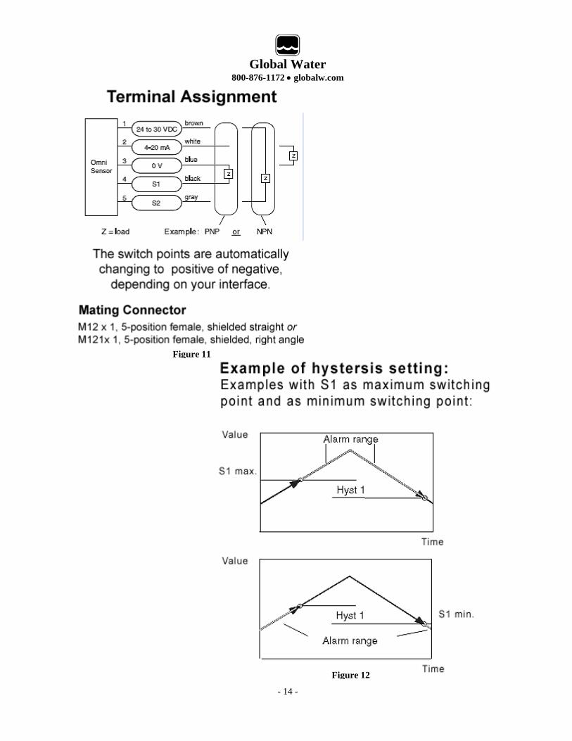
Ohm resistor to 0 V) Switching Values PNP or NPN selectable; 300 mA load sum max.; (S1 and S2) programmable as min. or max. value; short circuit proof; reverse polarity proof Hysterisis Adjustable; position depends on min. or max.
setting Display Graphical LCD display; temperature range -20°C
to 70°C (-4°F to 158°F); 32x16 pixels; back-lit LED signaling lamp
Connection M 12x1; 5-pole locking plug
Operational: Accuracy ±0.2% full scale Linearity Error <0.3% full scale Temperature Error 0.03% °C Operating Temperature 0°C to 70°C (32°F to 158°F) Operating Pressure Ambient
Approval CE, IP67 (Totally protected against dust, protected against the effects of immersion between 0 – 1 meter)
- 4 -
Global Water
800-876-1172 • globalw.com
Range WL750-4 0.66 ft. to 4.3 ft. WL750-8 0.98 ft. to 7.5 ft
Mechanical:
Wetted Materials PET 30% GV, epoxy resin, POM Housing Materials Stainless steel, tempered glass, POM ring
Housing Flange mount with center hole 35.5mm and three fastening through holes for screws or bolts
- 5 -
Global Water
800-876-1172 • globalw.com
IV. Operation
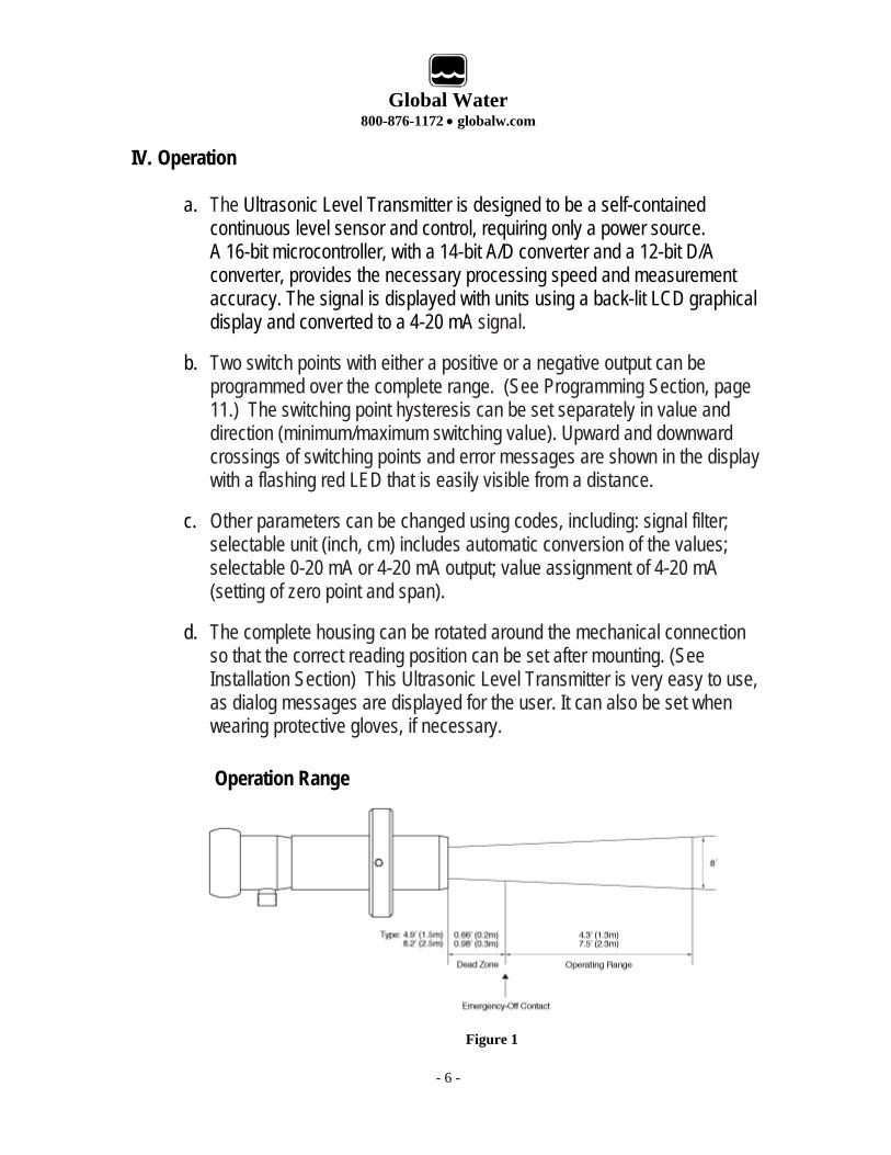
a. The Ultrasonic Level Transmitter is designed to be a self-contained continuous level sensor and control, requiring only a power source. A 16-bit microcontroller, with a 14-bit A/D converter and a 12-bit D/A converter, provides the necessary processing speed and measurement accuracy. The signal is displayed with units using a back-lit LCD graphical display and converted to a 4-20 mA signal.
b. Two switch points with either a positive or a negative output can be programmed over the complete range. (See Programming Section, page 11.) The switching point hysteresis can be set separately in value and direction (minimum/maximum switching value). Upward and downward crossings of switching points and error messages are shown in the display with a flashing red LED that is easily visible from a distance.
c. Other parameters can be changed using codes, including: signal filter; selectable unit (inch, cm) includes automatic conversion of the values; selectable 0-20 mA or 4-20 mA output; value assignment of 4-20 mA (setting of zero point and span).
d. The complete housing can be rotated around the mechanical connection so that the correct reading position can be set after mounting. (See Installation Section) This Ultrasonic Level Transmitter is very easy to use, as dialog messages are displayed for the user. It can also be set when wearing protective gloves, if necessary.
- 6 -
Operation Range
Figure 1
Global Water
800-876-1172 • globalw.com
V. Installation
Sensor Installation: The sensor uses a flange-type mounting scheme. Generally, the sensor must be located so that the signal path is free of obstructions. The sensor should be mounted level and perpendicular to the surface of the material to be monitored. If the vessel has a sloped top, consider using a self-aligning bulkhead fitting or a flange fitting with a riser that will allow the sensor to be positioned relative to the material's surface. Swivel mounts are a good choice in resolving this type of installation problem. The use of a mounting bracket would be for open-topped tanks, sumps or reservoirs. If the installation will have large electrical equipment situated near the sensor, then earthed steel conduit must be used.
- 7 -
Global Water
800-876-1172 • globalw.com
VI. Programming
a. Programming Overview The programming ring can be rotated from the Neutral center position to Position 1 and Position 2. The following actions are possible: A – Display of parameters with Position 1 (simultaneous display of the set parameters) – Turn the programming ring left to Position 1 to begin cycling through these programming parameters: Switching points S1 and S2, Hysteresis direction of S1 and S2, Hysteresis Hyst 1 and Hyst 2, Code (allows editing of additional parameters), Filter, Units, Output, 4 mA Value and 20 mA value. See following pages for detailed programming instructions. B – Editing with Position 2 Turn the programming ring to the right to Position 2 and a flashing cursor appears showing the position to be changed. With repeated turning to Position 2, the values are increased. By turning to Position 1, you obtain the next position. Each position can be edited in this way. If there is no action within 5 seconds, the device returns to the normal display section without the change being accepted, and you will have to cycle through the program again. C – Saving the change with Position 1 Turning one time toward Position 1 after quitting the last value signifies acceptance of the change.
b. Programming Protection The programming ring can be pulled off, inverted, and replaced. This will prevent further programming resulting from turning the ring in either direction. (See Protecting your Programming Parameters section.)
- 8 -
Global Water
800-876-1172 • globalw.com
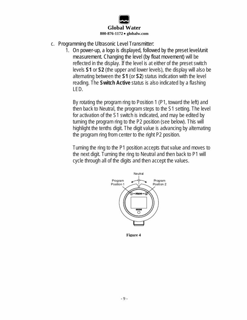
c. Programming the Ultrasonic Level Transmitter: 1. On power-up, a logo is displayed, followed by the preset level/unit
measurement. Changing the level (by float movement) will be reflected in the display. If the level is at either of the preset switch levels S1 or S2 (the upper and lower levels), the display will also be alternating between the S1 (or S2) status indication with the level reading. The Switch Active status is also indicated by a flashing LED. By rotating the program ring to Position 1 (P1, toward the left) and then back to Neutral, the program steps to the S1 setting. The level for activation of the S1 switch is indicated, and may be edited by turning the program ring to the P2 position (see below). This will highlight the tenths digit. The digit value is advancing by alternating the program ring from center to the right P2 position. Turning the ring to the P1 position accepts that value and moves to the next digit. Turning the ring to Neutral and then back to P1 will cycle through all of the digits and then accept the values.
Figure 4
- 9 -
Global Water
800-876-1172 • globalw.com
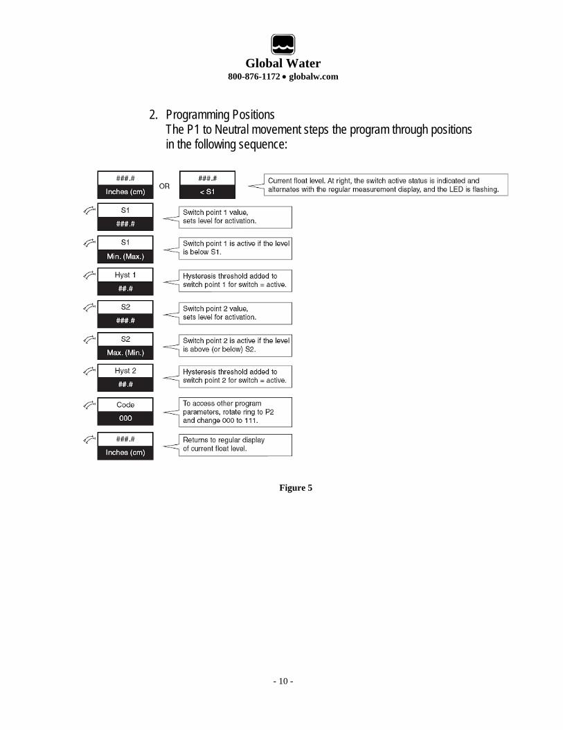
2. Programming Positions
The P1 to Neutral movement steps the program through positions in the following sequence:
Figure 5
- 10 -
Global Water
800-876-1172 • globalw.com
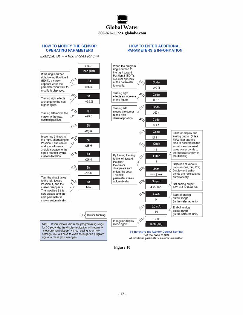
3. Modifying Operating Parameters
From any of the Programming Position steps noted in Figure 5 on page13, follow these steps to modify the operating parameter:
a) Turn the programming ring to the right to Position 2, and then back to Neutral, to bring up the editing cursor in the first decimal place. b) Turning the ring to the right and back to Neutral increases the current decimal place to the next highest value. c) Turning the ring to the left and back to Neutral moves the cursor on to the next decimal position. Repeat step 2 to edit the current position. d) To confirm the new value, continue to turn the ring to the left and back to neutral until you cycle through all of the decimal places and the next parameter shows on the display.
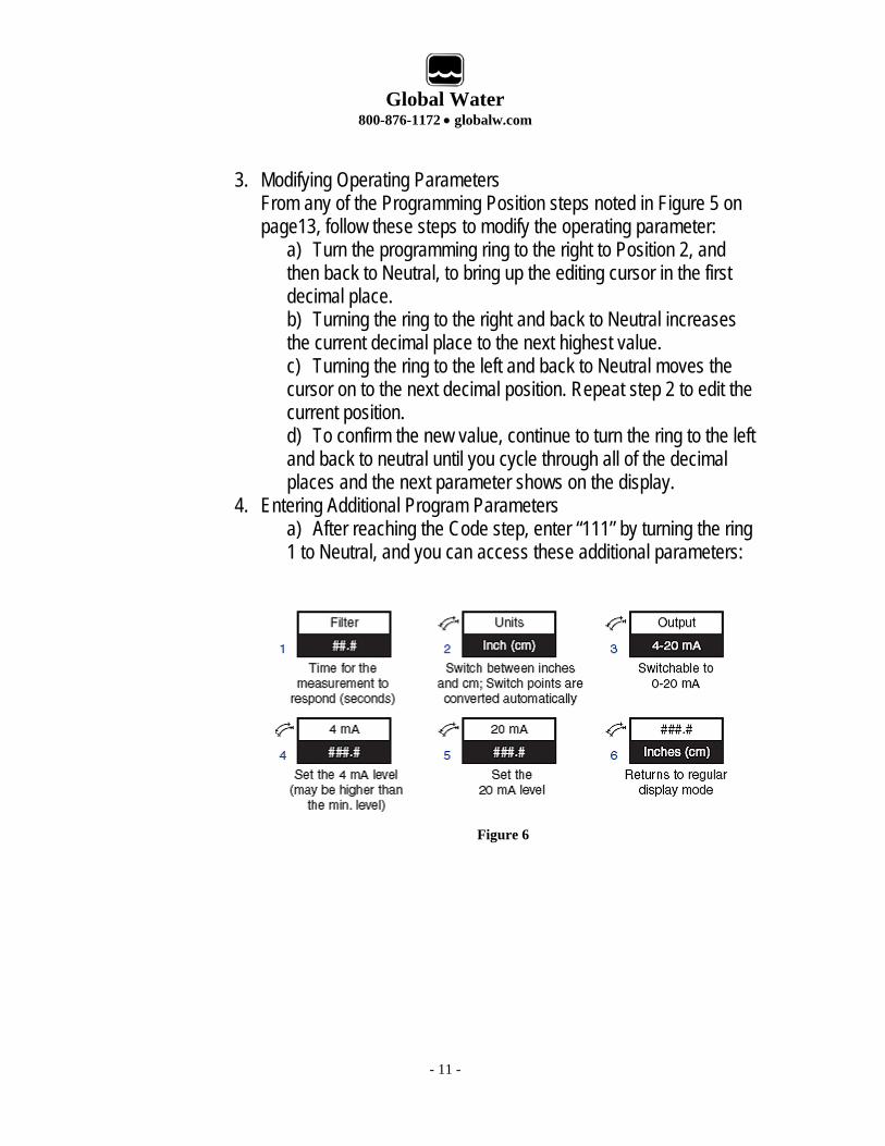
4. Entering Additional Program Parameters a) After reaching the Code step, enter “111” by turning the ring 1 to Neutral, and you can access these additional parameters:
Figure 6
- 11 -
Global Water
800-876-1172 • globalw.com
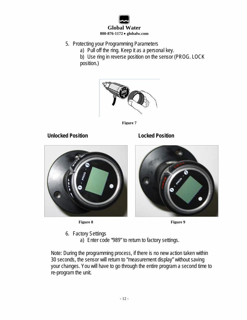
5. Protecting your Programming Parameters a) Pull off the ring. Keep it as a personal key. b) Use ring in reverse position on the sensor (PROG. LOCK position.)
Figure 7
Figure 8 Figure 9
Unlocked Position Locked Position
6. Factory Settings a) Enter code “989” to return to factory settings.
Note: During the programming process, if there is no new action taken within 30 seconds, the sensor will return to “measurement display” without saving your changes. You will have to go through the entire program a second time to re-program the unit.
- 12 -
Global Water
800-876-1172 • globalw.com
Figure 10
- 13 -
Global Water
800-876-1172 • globalw.com
- 14 -
Figure 11
Figure 12
Global Water
800-876-1172 • globalw.com
VII. Maintenance
a. The unit must be checked periodically. The suggested maintenance rate depends on the installation area. Check batteries for correct voltage periodically.
VIII. Trouble Shooting
a. Call us for tech support: 800-876-1172 or 916-638-3429 (many problems can be solved over the phone). Fax: 916-638-3270 or Email: [email protected]. Be prepared to describe the problem you are experiencing including specific details of the application and installation and any additional pertinent information.
b. In the event that the equipment needs to be returned to the factory for any
reason, please call to obtain an RMA# (Return Material authorization). Do not return items without an RMA# displayed on the outside of the package. Clean and decontaminate the Ultrasonic Level Transmitter, if necessary. Include a written statement describing the problems. Send the package with shipping prepaid to our factory address. Insure your shipment, as the warranty does not cover damage incurred during transit.
c. When calling for tech support, please have the following information ready:
1. Model #. 2. Unit serial number. 3. P.O.# the equipment was purchased on. 4. Our sales order number or the invoice number. 5. Repair instructions and/or specific problems relating to the product.
- 15 -
Global Water
800-876-1172 • globalw.com
IX. Warranty
a. Global Water Instrumentation, Inc. warrants that its products are free from defects in material and workmanship under normal use and service for a period of one year from date of shipment from factory. Global Water’s obligations under this warranty are limited to, at Global Water’s option: (I) replacing or (II) repairing; any products determined to be defective. In no case shall Global Water’s liability exceed the products original purchase price. This warranty does not apply to any equipment that has been repaired or altered, except by Global Water Instrumentation, Inc., or which has been subject to misuse, negligence or accident. It is expressly agreed that this warranty will be in lieu of all warranties of fitness and in lieu of the warranty of merchantability.
b. The warranty begins on the date of your invoice.
- 16 -