global review of spray-on structural lining technologies - water
TRANSCRIPT

Global Review of Spray-On Structural Lining Technologies
Subject Area: Infrastructure


Global Review of Spray-On Structural Lining Technologies
©2010 Water Research Foundation. ALL RIGHTS RESERVED
About the Water Research Foundation
The Water Research Foundation (formerly Awwa Research Foundation or AwwaRF) is a member-supported, international, 501(c)3 nonprofit organization that sponsors research to enable water utilities, public health agencies, and other professionals to provide safe and affordable drinking water to consumers.
The Foundation’s mission is to advance the science of water to improve the quality of life. To achieve this mission, the Foundation sponsors studies on all aspects of drinking water, including resources, treatment, distribution, and health effects. Funding for research is provided primarily by subscription payments from close to 1,000 water utilities, consulting firms, and manufacturers in North America and abroad. Additional funding comes from collaborative partnerships with other national and international organizations and the U.S. federal government, allowing for resources to be leveraged, expertise to be shared, and broad-based knowledge to be developed and disseminated.
From its headquarters in Denver, Colorado, the Foundation’s staff directs and supports the efforts of more than 800 volunteers who serve on the board of trustees and various committees. These volunteers represent many facets of the water industry, and contribute their expertise to select and monitor research studies that benefit the entire drinking water community.
The results of research are disseminated through a number of channels, including reports, the Web site, Webcasts, conferences, and periodicals.
For its subscribers, the Foundation serves as a cooperative program in which water suppliers unite to pool their resources. By applying Foundation research findings, these water suppliers can save substantial costs and stay on the leading edge of drinking water science and technology. Since its inception, the Foundation has supplied the water community with more than $460 million in applied research value.
More information about the Foundation and how to become a subscriber is available on the Web at www.WaterResearchFoundation.org.
©2010 Water Research Foundation. ALL RIGHTS RESERVED
Global Review of Spray-On Structural Lining Technologies
Jointly sponsored by:Water Research Foundation6666 West Quincy Avenue, Denver, CO 80235-3098
and
U.S. Environmental Protection AgencyWashington, D.C.
Published by:
Prepared by:Dan Ellison, Firat Sever, Peter Oram, Will Lovins, and Andrew RomerAECOM5851 Thille Street, Suite 201, Ventura, CA 93003
Steven J. DuranceauUniversity of Central Florida, Orlando, Florida
and
Graham BellSchiff Associates
©2010 Water Research Foundation. ALL RIGHTS RESERVED

DISCLAIMER
This study was jointly funded by the Water Research Foundation (Foundation) and the U.S. Environmental Protection Agency (USEPA) under Cooperative Agreement No. CR-83110401. The
Foundation or USEPA assume no responsibility for the content of the research study reported in this publication or for the opinions or statements of fact expressed in the report. The mention of trade names for commercial products does not represent or imply the approval or endorsement of the
Foundation or USEPA. This report is presented solely for informational purposes.
Copyright © 2010by Water Research Foundation
ALL RIGHTS RESERVED. No part of this publication may be copied, reproduced
or otherwise utilized without permission.
ISBN 978-1-60573-094-3
Printed in the U.S.A.
©2010 Water Research Foundation. ALL RIGHTS RESERVED

v
CONTENTS LIST OF TABLES ......................................................................................................................... ix LIST OF FIGURES ....................................................................................................................... xi FOREWORD .................................................................................................................................xv ACKNOWLEDGMENTS .......................................................................................................... xvii EXECUTIVE SUMMARY ......................................................................................................... xix CHAPTER 1: INTRODUCTION AND OVERVIEW ....................................................................1
The Need for Structural Lining ............................................................................................1 Current Structural Rehabilitation Methods and Their Limitations ......................................3 The Potential Benefits of Spray-On Structural Lining ........................................................4 What Makes a Lining “Structural”? .....................................................................................5 Research Methodology ........................................................................................................8
Literature Search and Review ..................................................................................8 Interviews/Correspondence with Pipeline Rehabilitation Leaders ..........................8 Technical Workshop ................................................................................................8 Manufacturer Testing ...............................................................................................9 Bench Testing ..........................................................................................................9 Case Studies and Video Recording ........................................................................10
Preface Notes .....................................................................................................................10 United Kingdom Pipeline Rehabilitation ...............................................................10 Units of Measure ....................................................................................................10 Name of Manufacturers .........................................................................................10
CHAPTER 2: BACKGROUND, HISTORY AND CURRENT PRACTICE ...............................11
General Assessment of Water Industry Infrastructure .......................................................11 Other Reasons to Line Pipe................................................................................................13
Water Quality Protection/Improvement .................................................................13 Hydraulic Improvements .......................................................................................15 Water Main Rehabilitation Market ........................................................................17
Cement-Mortar Lining History and Properties ..................................................................18 CML History ..........................................................................................................18 Structural Limitations ............................................................................................18 Fiber Reinforcement ..............................................................................................19 Hole Spanning ........................................................................................................19
Spray-On Polymer Linings – History and Properties ........................................................21 Epoxy ................................................................................................................................22 Polyurethane and Polyurea ................................................................................................23 The Process of Cleaning and Lining ..................................................................................24 Quality Control Issues and Utility Acceptance ..................................................................27
©2010 Water Research Foundation. ALL RIGHTS RESERVED

vi | Global Review of Spray-On Structural Lining Technologies
The Life Expectancy of Polymer Linings ..........................................................................29 Other (Non-Spray Applied) Lining Methods .....................................................................30
Structural and Semi-Structural Linings – Definitions ...........................................31 Service Reinstatement ............................................................................................31 The Advantages (and Disadvantages) of Good Liner Adhesion ...........................33
CHAPTER 3: STRUCTURAL PROPERTIES AND POTENTIALS OF POLYMER
LINING ....................................................................................................................................35 The Structural Properties of Polymer Linings ...................................................................35 Hoop Stress Resistance of a Lined Pipe ............................................................................37
Why Polymer Linings May Not Provide Usable Hoop Strength ...........................39 Hole and Gap Spanning .....................................................................................................40 Pipe Bending ......................................................................................................................44
Detachment of the Lining is Critical to Lining Survival .......................................46 Adhesion to Pipe Walls ......................................................................................................47
Adhesion During Installation .................................................................................47 Adhesion After Curing of the Spray-on Lining .....................................................48
Lining Buckling Due to External Loads or Vacuum .........................................................49 Predicting the Long-Term Behavior of Polymeric Materials ............................................49
Failure Stages .........................................................................................................50 Long-term Estimates of Strength for Plastic Materials are Extrapolations ...........52 Molecular Structure and Polymer Strength ............................................................53 Oxidation and Chemical Degradation ....................................................................54
Other Possible Lining Materials and Variations ................................................................55 Alternative Resins ..................................................................................................55 Fillers .....................................................................................................................55 Thermoplastics .......................................................................................................56
Use of Nano- and Micro- Particle Composites in Spray-on Linings .................................57 CHAPTER 4: STRUCTURAL TESTS OF POLYMER LINING BY MANUFACTURERS .....61
Hoop Stress Resistance Test ..............................................................................................61 Lining D – Short-Term Hydrostatic Burst Tests.................................................61
Hole Spanning and Bridging Tests ....................................................................................62 Lining A – Hole Spanning Test ..........................................................................63 Lining D – Hole Bridging Demonstration ..........................................................64 Lining E – Hole Bridging Demonstration ...........................................................64 Lining E – Hole Spanning Test ...........................................................................65 Lining F – Hole Spanning Test ...........................................................................66
Gap Spanning Tests ...........................................................................................................68 Lining D – Gap Spanning Tests and Demonstrations .........................................69 Lining E – Gap Bridging and Spanning, Demonstrations and Tests ..................74
Pipe Breaking Tests ...........................................................................................................75 Lining Adhesion / Buckling Tests .....................................................................................76 Strengthening for External Load ........................................................................................77
©2010 Water Research Foundation. ALL RIGHTS RESERVED

Contents | vii
CHAPTER 5: LABORATORY TESTING OF MAINS LINED IN-PLACE WITH HIGH-BUILD POLYMER ..............................................................................................................79
Pipe Fracture Test – Purpose .............................................................................................79 Pipe Fracture Test – Concept .............................................................................................80 Pipe Fracture Test – Set Up ...............................................................................................81 Pipe Fracture Test – Results ..............................................................................................82 Results of Other Laboratory Tests .....................................................................................84
Adhesion Tests ....................................................................................................85 Lining Thickness Evaluations .............................................................................85 Differential Scanning Calorimetry and Fourier Transform Infrared
Spectroscopy ....................................................................................................85 Mechanical Properties .........................................................................................86
Discussion of Test Results .................................................................................................87 Pipe Fracture Tests – Potential Benefits .............................................................87 Pipe Fracture Testing was Inconclusive .............................................................88 Other Concerns Regarding the Lack of Adhesion ..............................................89 Material Properties – Implications Regarding Structural Lining ........................90
CHAPTER 6: WATER QUALITY, HEALTH AND REGULATORY CONSIDERTIONS .......91
NSF/ANSI Standard 61 Drinking Water System Components .........................................91 Deterioration of Polymeric Materials ................................................................................93
Contaminant Indicators .......................................................................................93 Water Quality Monitoring...................................................................................94 Taste and Odor Issues .........................................................................................94 Cement Mortar Linings .......................................................................................94 Epoxy Linings .....................................................................................................95 Polyurethane Linings ..........................................................................................97 Leachate, Volatile Organic Compounds, and HDPE ..........................................97 PVC and PE ........................................................................................................98
Disinfectant Residuals, Water Absorption and Polymeric Materials ................................99 Biofilm Considerations ....................................................................................................101
Polyvinyl Chloride (PVC) and Polyethylene (PE)............................................101 Epoxy Linings ...................................................................................................102 Cement Mortar Linings .....................................................................................102
Endocrine Disruptors .......................................................................................................103 Cure Times .......................................................................................................................104
1. Weight Check/Mix Ratio ..............................................................................104 2. Temperature ..................................................................................................104 3. Disinfection ...................................................................................................105
General Conclusions – Health Issues Associated with Pipe Living ................................105 CHAPTER 7: CASE STUDIES...................................................................................................107
Use of Polymeric Linings in the United Kingdom ..........................................................107 Background .......................................................................................................107 Lining Program Development ...........................................................................110 Contract Mechanisms ........................................................................................111
©2010 Water Research Foundation. ALL RIGHTS RESERVED
viii | Global Review of Spray-On Structural Lining Technologies
Polymeric Material Selection ............................................................................111 Lining Application Issues .................................................................................112 Quality Control .................................................................................................113 Lessons Learned ................................................................................................113
Southwest Water – Rehabilitation Program .....................................................................114 U.S. Case Study ...............................................................................................................115 Sandwich Water District, MA – Same-Day Return to Service Attempt ..........................116
Background .......................................................................................................116 Lining Trial .......................................................................................................116 Contract .............................................................................................................117 Lining Program .................................................................................................117 Conclusions Regarding Sandwich Water District Project ................................118
APPENDIX A: WORKSHOP PARTICIPANTS .......................................................................121 APPENDIX B: TESTING LABORATORY REPORT ..............................................................123 APPENDIX C: SOUTH WEST WATER – PROCEDURE FOR RENOVATED MAINS
DISINFECTION AND CLEARANCE .................................................................................143 REFERENCES ............................................................................................................................149 ABBREVIATIONS .....................................................................................................................157
©2010 Water Research Foundation. ALL RIGHTS RESERVED

ix
TABLES
1.1 Calculated Minimum Living Thickness Needed for Stand-alone Epoxy Lining ................6 2.1 Headloss Comparisons for Different Lining Thicknesses (based on flow of 200 gpm
and 1000 feet of pipe) ............................................................................................17 3.1 Mechanical Properties of Various Polymeric Lining and Pipeline Materials ....................36 3.2 Calculated Minimum Lining Thickness Needed for Stand-alone Lining (based on high- strength polymeric material) ..................................................................................37 3.3 Calculated Hole Spanning for Polymer Lining Based on Bi-axial Plate Bending ............42 3.4 Gap-Spanning Predictions – 3mm (0.12 inch) Spray-on Lining in 100 mm (4 inch)
Pipe ........................................................................................................................44 4.1 Short-term Hydrostatic Burst Test of 4-inch (100 mm) Lining .........................................62 4.2 Short-term Hydrostatic Burst Test of 8-inch (200 mm) Lining .........................................62 4.3 Shear Stress at Failure for Lining A ..................................................................................64 4.4 Gap-Spanning Predictions and Results – 3 mm (0.12 inch) Spray-on Lining in
100 mm (4 inch) Pipe .............................................................................................71 5.1 Charpy Impact Testing Results – Lining D .......................................................................87
©2010 Water Research Foundation. ALL RIGHTS RESERVED

©2010 Water Research Foundation. ALL RIGHTS RESERVED

xi
FIGURES 2.1 Total 20-year need to be invested into drinking water infrastructure based on the
2005 USEPA Report (in billion dollars) ...............................................................11 2.2 A water break in 2001 from a town in Iowa (Image courtesy of City of Dubuque) ..........12 2.3 Water main break in 2008, near Washington D.C. (Photo courtesy of Bill O’Leary,
Washington Post). ..................................................................................................13 2.4 Conventional epoxy lining before and after (Photo courtesy of HydraTech Engineered
Products LLC) ........................................................................................................14 2.5 Tuberculation in 4-inch cast iron water main (Source: WaterRF) .....................................16 2.6 Exposed Cement Mortar Lining in 36-inch riveted steel pipeline (Photo courtesy of
Michael E. Grahek) ...............................................................................................20 2.7 Molecular structure of epoxy (Source: wikipedia.com) ....................................................23 2.8 Epoxy spinner-head being inserted into a deteriorated pipe (Source: WRc Group,
UK) ........................................................................................................................23 2.9 Polyurethane production by poly addition of diisocyanate and polyol (Source: Shiwei
William Guan, 2003) .............................................................................................24 2.10 Bypass piping system in Los Angeles (Photo courtesy ofMichael E. Grahek). ................25 2.11 Access pit for cleaning pipe (Photo courtesy of Michael E. Grahek) ................................26 2.12 Drag scraper (Photo courtesy of Michael E. Grahek) ........................................................26 2.13 Rack-feed boring machine. (Photo courtesy of AdTec International, Inc.) ......................27 2.14 Tight-fit slip lining or CIPP Lining, prior to service reinstatement (Source: Ellison,
2007) ......................................................................................................................32 2.15 Pipe bursting and loose-fit slip lining, prior to service reinstatement (Source: Ellison,
2007) ......................................................................................................................32 2.16 Pipe bursting and loose-fit slip lining, prior to service reinstatement (Source: Ellison,
2007) ......................................................................................................................32 2.17 Spray-on structural lining condition – no service reinstatement required (Source:
Ellison, 2007) .........................................................................................................33
©2010 Water Research Foundation. ALL RIGHTS RESERVED

xii | Global Review of Spray-On Structural Lining Technologies
3.1 Lining spanning hole, with long-term deformation. ..........................................................41 3.2 Expected relationship between hole or gap size, lining thickness and pressure at
failure for a given material, time, and temperature. ...............................................42 3.3 Lining spanning a gap caused by pipeline fracture. ...........................................................46 3.4. Failure of elastomeric polyurethane lining (Photo courtesy of Madison Chemical Industries). .............................................................................................................48 3.5. Failure modes of polymeric pipe/lining over time. (Source: Gray et al., 1981.
Reproduced with permission from Maney Publishing: www.maney.co.uk/hournals/prc) ...........................................................................51
3.6. Reduction in ultimate flexural strength of CIPP specimens after exposure to chlorine,
chloramines, and fluoride solutions. ......................................................................55 3.7. A segment of a broken LDPE specimen had been exposed to 80 ºC for 5,000 hours.
Note the cracks which developed over the surface, indicative of oxidation/ embrittlement (Sever, 2006). .................................................................................56
3.8. Tensile modulus of elasticity versus percent weight of modifiers which are produced
from clays and aluminum silicates. Zero percent weight indicates unmodified epoxy (Source: Kinloch and Taylor, 2006). ...........................................................58
3.9. Fracture surface of epoxy resin with poor (a) and good mixing (b). Clay particles can be
easily seen in case of poor mixing (Source: Zhao and Hoa) ..................................59 4.1. Pressure testing of Lining A (Photo courtesy of Warren Environmental) .........................63 4.2. Lining E - hole bridging test (Photo courtesy of Subterra) ................................................65 4.3. Lining E - hole spanning test (Photo courtesy of Subterra ) ..............................................66 4.4. Lining F - hole spanning test set up (Photo courtesy of Sprayroq, Inc.) ...........................66 4.5. Panel Sandwich (Photo courtesy of Sprayroq, Inc.) ..........................................................67 4.6. Instrumentation of 3-inch opening (Photo courtesy of Sprayroq, Inc.) .............................67 4.7. Rupture pressures for panels spanning a 3-inch diameter opening (Source:
Sprayroq, Inc.) .......................................................................................................67 4.8. Lining F panel deformations (Source: Sprayroq, Inc.) ......................................................68 4.9. Lining D - Initial Set Up (Photo courtesy of 3M Company). ............................................70
©2010 Water Research Foundation. ALL RIGHTS RESERVED

Figures | xiii
4.10. Lining D - Final Set Up (Photo courtesy of 3M Company). .............................................70 4.11 a (edge cut), b (blow out) and c (mid-span pin hole) Arrows show failures. (Photo
courtesy of 3M Company) .....................................................................................70 4.12. Angular deflection demonstration for Lining D (Photo courtesy of 3M Company) .........72 4.13. Test report for axial displacement demonstration (Source: 3M Company). ......................72 4.14. Shearing demonstration for Lining D (Photo courtesy of 3M Company). ........................73 4.15. Gap bridging demonstration for Lining E (Photo courtesy of Subterra). ..........................74 4.16. Gap spanning test for Lining E (Photo courtesy of Subterra) ............................................75 4.17. Pipe fracture test with Lining D (Photo courtesy of 3M Company) ..................................76 4.18. Strength increase due to epoxy lining of RCP specimens. (The data used to generate
this graph was taken from a report furnished by Warren Environmental.) ...........78 5.1. Set up concept for pipe fracture test. .................................................................................80 5.2. Actual set up for pipe fracture test. ....................................................................................82 5.3. Initial cracking of specimens .............................................................................................83 5.4. Initial cracking of specimens .............................................................................................83 5.5. Initial cracking of specimens .............................................................................................83 5.6. Initial cracking of specimens .............................................................................................83 5.7. Initial cracking of specimens .............................................................................................83 5.8. Deflection needed for tearing of lining ..............................................................................84 5.9. Deflection needed for tearing of lining ..............................................................................84 5.10. Gaps visible between pipe and lining. Figure 5.10 also shows lining tear produced from
severe angular deflection. Figure 5.11 shows slumping of the lining material before curing. .........................................................................................................85
5.11. Gaps visible between pipe and lining. Figure 5.10 also shows lining tear produced from
severe angular deflection. Figure 5.11 shows slumping of the lining material before curing. .........................................................................................................85
©2010 Water Research Foundation. ALL RIGHTS RESERVED

xiv | Global Review of Spray-On Structural Lining Technologies
5.12. Pipe sample taken from near an entry or exit pit ...............................................................90 6.1 Remaining polyurethane weight versus time (Zhu et al., 1999). .......................................98 7.1 Pipe lining and renewal in the UK 1990-2007 (OFWAT, 2008). ....................................108 7.2 Early trials with rapid curing polymer (Photo courtesy of AECOM). .............................110 7.3 Typical lining rig material reservoirs, pumping system and hose reel (L), application
head and pre-lining testing (R) (Photo courtesy of AECOM). ............................111 7.4 Examples of lining defects (Photo courtesy of AECOM). ..............................................112 7.5 Lining application on AC (L), lining rig in position on site (R) (Photo courtesy of
AECOM). .............................................................................................................118
©2010 Water Research Foundation. ALL RIGHTS RESERVED
xv
FOREWORD The Water Research Foundation (Foundation) is a nonprofit corporation that is dedicated
to the implementation of a research effort to help utilities respond to regulatory requirements and traditional high-priority concerns of the industry. The research agenda is developed through a process of consultation with subscribers and drinking water professionals. Under the umbrella of a Strategic Research Plan, the Research Advisory Council prioritizes the suggested projects based upon current and future needs, applicability, and past work; the recommendations are forwarded to the Board of Trustees for final selection. The Foundation also sponsors research projects through an unsolicited proposal process; the Collaborative Research, Research Applications, and Tailored Collaboration programs; and various efforts with organizations such as the U.S. Environmental Protection Agency, the U.S. Bureau of Reclamation, and the Association of California Water Agencies.
This publication is a result of one of these sponsored studies, and it is hoped that its findings will be applied throughout the world. The following report serves not only as a means of communicating the results of the water industry’s centralized research program but also as a tool to enlist the further support of the nonmember utilities and individuals.
Projects are managed closely from their inception to the final report by the Foundation’s staff and large cadre of volunteers who willingly contribute their time and expertise. The Foundation serves a planning and management function and awards contracts to other institutions such as water utilities, universities, and engineering firms. The funding for this research effort comes primarily from the Subscription Program, through which water utilities subscribe to the research program and make an annual payment proportionate to the volume of water they deliver and consultants and manufacturers subscribe based on their annual billings. The program offers a cost-effective and fair method for funding research in the public interest.
A broad spectrum of water supply issues is addressed by the Foundation’s research agenda: resources, treatment and operations, distribution and storage, water quality and analysis, toxicology, economics, and management. The ultimate purpose of the coordinated effort is to assist water suppliers to provide the highest possible quality of water economically and reliably. The true benefits are realized when the results are implemented at the utility level. The Foundation’s trustees are pleased to offer this publication as a contribution toward that end.
David E. Rager Robert C. Renner, P.E. Chair, Board of Trustees Executive Director Water Research Foundation Water Research Foundation
©2010 Water Research Foundation. ALL RIGHTS RESERVED

©2010 Water Research Foundation. ALL RIGHTS RESERVED
xvii
ACKNOWLEDGMENTS
The authors of this report wishes to acknowledge the contributions made by the various
researchers and authors whose works are the references for this report. Special thanks are due to the following people and organizations who each gave time, materials, and effort directly to this project:
Water Research Foundation Project Manager: Jian Zhang, Water Research Foundation, Denver, CO
Water Research Foundation Project Advisory Committee:
Vill Villanueva, City of Portland Water Bureau, Portland, OR Ray Sterling, Louisiana Tech University, Ruston, LA Peter Robert Duffy, United Utilities NW, Great Sankey, Warrington, United Kingdom
Major Contributors:
AECOM Schiff Associates Bodycote, LLC 3M Company Subterra
Other Participants:
Tim Ball, Infrastructure Renewal Services, Middletown, KY Derrick Horsman, Alltech Solutions, New Brunswick, Canada Norman Howell, Subterra, Lancashire PRI, UK John DeRosa, Subterra, Lancashire, PRI, UK Jon Mactaggert, Hunting Coatings, Cincinnati, OH Graeme Hill, HydraTech Engineered Products, LLC, Cincinnati, OH Leonard Assard, Heitkamp, Watertown, CT Joerg Kruse, International Pipeline Technology, San Diego, CA Eric Kim, Los Angeles Department of Water & Power, Los Angeles, CA David Heumann, Los Angeles Department of Water & Power, Los Angeles, CA Michael Grahek, Los Angeles Department of Water & Power, Los Angeles, CA Ted Norris, Regional Water Authority, New Haven, CT Brian Lakin, Regional Water Authority, New Haven, CT A. Rony Joel, Marco Island Utilities, Marco Island, FL Bart Bradshaw, Marco Island Utilities, Marco Island, FL Rick Sakaji, East Bay MUD, Oakland, CA David Lee, East Bay MUD, Oakland, CA Bill Cain, East Bay MUD, Oakland, CA Eric Fieberling, East Bay MUD, Oakland, CA Ken Morgan, City of Charlotte, Charlotte, NC Doug Sanders, A&W Maintenance, Inc., Carver, MA Danny Warren, A&W Maintenance, Inc., Carver, MA
©2010 Water Research Foundation. ALL RIGHTS RESERVED

xviii | Global Review of Spray-On Structural Lining Technologies
Colin Thackeray, 3M Company, North Yorkshire, UK Gary Natwig, 3M Company, Austin, TX Les Metcalfe, South West Water Limited, Devon, UK Amalia Abdelwahab, University of Central Florida, Orlando, FL Piero Salvo, Genivar, Montreal, Quebec, Canada Lynn Osborn, Instituform Technologies, Inc., Chesterfield, MO Steve Wierzchowski, RLS Solutions, Broken Arrow, OK Joanne Hughes, Cohesant, Inc., Broken Arrow, OK Donald Dancy, Innovative Painting & Waterproofing, Brea, CA Ross Mitchell, Madison Chemical Industries, Milton, Ontario, Canada Dave Purkiss, NSF International, Ann Arbor, MI Chip Johnson, Sprayroq, Inc., Birmingham, AL Jerry Gordon, Sprayroq, Inc., Birmingham, AL Doug Seargeant, Epcor Water Services, Edmonton, Alberta, Canada Roger Wood, Sydney Water Company, Sydney, Australia
©2010 Water Research Foundation. ALL RIGHTS RESERVED

xix
EXECUTIVE SUMMARY OBJECTIVES
The purpose of this project was to examine the structural abilities of spray-on linings.
Although the history and structural properties of cement mortar lining was also discussed, the focus was largely on polymeric linings: epoxy, polyurethane, and polyurea, and what structural benefits might be obtained from using these linings. BACKGROUND
The spray application of linings to water pipes is the oldest method of pipeline
rehabilitation, but since its inception, this method has often been characterized as “non-structural.” The primary purposes of spray-on linings have been to stop internal corrosion, restore hydraulic capacity, and eliminate water quality deterioration arising from iron or steel corrosion and associated scaling. However, it’s also been recognized that spray-on linings provide some structural benefit, primarily by spanning across rust holes and other areas of weakness in the pipe. In 1940, the City of Detroit determined through testing that 0.5-inch (12 mm) cement mortar lining could in fact span a 6-inch (150 mm) hole, resisting over 200 psi (13 bar) of internal pressure.
Despite this hole-spanning ability, the structural benefits of spray-on linings have often been considered insignificant, partly due to the inherent cracking and other weaknesses of unreinforced cement mortar, the first spray-applied lining. Although hole spanning could occur, the structural value of the unreinforced cement mortar lining was not considered reliable. Early polymer linings were also considered non-structural because when applied at a nominal thickness of only 1 mm, these epoxy linings could not span significant holes or other weaknesses. If applied at greater thicknesses, slumping of the lining material often occurred.
In the last decade, the industry has seen the development and adoption of faster-curing polyurethane and polyurea linings. Because these linings cure more quickly, they are more easily applied at greater thicknesses. Many of these polyurethane and polyurea linings also exhibit considerable tensile strength, making their use for structural rehabilitation potentially attractive. APPROACH
This study was initiated with an expert workshop and an extensive literature review. The
workshop led the research team to various unpublished reports, which provided most of the testing information that is presented. This research also led to the development of new laboratory tests performed on samples of in-situ lined cast iron pipe. Case studies were also developed, which describe how these linings are currently being applied in North America and the United Kingdom.
©2010 Water Research Foundation. ALL RIGHTS RESERVED

xx | Global Review of Spray-On Structural Lining Technologies
RESULTS/CONCLUSIONS Manufacturer Sponsored Tests
Hole and Gap Spanning. There is no question that spray-on linings have the ability in the short term to span holes and gaps in water mains. In fact, with high-build applications, the spanning can be impressive. A variety of tests performed on different products in recent years (mostly under the sponsorship of manufacturers) have demonstrated this. These tests show that high-build polymer linings have the ability to span rather large holes and large gaps in host pipelines while resisting normal water system pressures, and can also sustain very high pressures when spanning smaller holes.
Hoop Strength. Calculations and at least one manufacturer test confirm that high-build polymer linings also have the potential to fully resist short-term hoop stresses induced by normal water pipeline pressures. But because of significant differences in elastic moduli between the flexible polymer linings and the stiffer host pipes, polymer linings should not be expected to add significant strength to a host pipe. Also, the mechanism by which the hoop stresses would pass from the host pipe to the lining is not clear. A well-adhered lining would tear if the host pipe fractures.
Test Limitations. It must be noted that the tests results presented above were all short in duration. The long-term performance of any plastic material depends on how much the material creeps. The standard strength criterion used in the design of most plastic pipe materials is the 100,000-hour (11.4 year) value. Other considerations in determining the long-term design strength of a plastic material are its resistances to slow crack growth and chemical degradation. It appears that few long-term strength tests and no long-term degradation tests have been performed on these materials.
Fracture Resistance. It has been well demonstrated that high-build polymeric linings can successfully span a small crack in a pipe. But a fundamental question is whether a lining can withstand the cracking of the pipe itself. The ability to withstand a pipe fracture would reduce the chance that a pipe fracture would produce a large, sudden release of water. Tests performed on one polyurea lining material for the manufacturer showed that the lining could endure a fracturing of the host pipe caused by bending of the pipe. Other tests by the manufacturer showed that once the pipe cracked, large angular and shear deflections could be endured without damage to the lining. However, a lack of internal pressure was considered a significant issue by the research team. With internal pressure, a frictional bond would exist between the lining and the pipe wall in addition to whatever bond had developed through adhesion of the polymer. Moreover, the team believes it is important to test old pipelines lined in the field because the roughness of decades-old pipe pitted by corrosion might result in considerably more friction between the lining and substrate. Laboratory Tests Performed for this Study
A testing plan was developed to further investigate the fracture resistance of this polyurea lining within old cast iron pipe. The primary purpose was to determine whether the internal pressure would create a frictional bond that would cause tearing of the lining when the pipe fractures. The lining survived in all five tests, with 50 psi (3.4 bar) of pressure within the pipes. The linings did not tear because they readily detached from the inside walls of the host pipes. In
©2010 Water Research Foundation. ALL RIGHTS RESERVED
Executive Summary | xxi
fact, the detachment was such that in all cases, pressure was released immediately when the pipes cracked. Water flowed though the annulus between the pipe wall and lining and out the fracture.
Unfortunately, these tests were determined to be inconclusive in demonstrating the survival of a lining during fracture of a pressurized pipe. There was evidence that the lining was at least partially detached from the host pipe before testing was started, and because of a change in the testing protocol, water had been allowed to enter the annulus prior to the fracture. This meant that pressure was likely equal on both sides of the lining and no added frictional bond existed.
The laboratory examinations found that the adhesion of this particular lining was so low that other issues arose regarding how well the lining might perform as either a structural lining or a corrosion barrier. Other tests performed for this study found relatively high long-term creep and relatively low resistance to slow crack growth for this particular lining. Creep rates and slow crack growth resistance are factors that need to be considered in determining the long-term structural performance of any plastic pipe material.
Health Concerns
This report also examines health issues related to polymer linings, particularly whether
harmful chemicals can leach from these linings. An extensive literature review showed that where the lining materials have been certified in accordance with ANSI/NSF Standard 61 and where work has been accomplished in accordance with strict application standards, threats to health are minimal. In fact, a good deal of evidence points to the public health benefits of cleaning and lining cast iron mains, with reductions in biofilm, heterotropic plate counts, coliform, and disinfectant demand.
One particular health issue is whether mains can be safely returned to service in less than one day, prior to confirming through testing that harmful bacteria are absent. One-day return to service is an important cost-saving issue as it avoids the need to establish bypass piping systems prior to lining. By some estimates, the cost of lining might be reduced by 30 percent, if bypass piping is not used. In the U.K., one-day return to service has become common and the results from years of tests on thousands of miles of pipeline have given the utilities confidence in the techniques that are used. In the United States, one-day return to service has been tried, but is not yet practiced due to market resistance that includes a greater number of regulatory agencies, a greater number of utilities, and a smaller overall market for water main rehabilitation.
APPLICATIONS/RECOMMENDATIONS
The objective of this study was to provide a technical assessment of spray-on linings for
North American water main applications, barriers to their acceptance, and methods to overcome these barriers. In many respects, linings are already well accepted in North America and have been for decades. Some cities, such as Los Angeles, have completely eliminated unlined pipe in their systems through long-running programs of spray-on lining. Without question, spray-on lining is the most common method of water main rehabilitation in the United States, but compared to the U.K., the level of activity is low. The reasons are the younger age of U.S. infrastructure, the greater fragmentation of the U.S. market, the greater diversity of regulators, and the less congested streets. These factors allow deferral of work, favor a traditional approach,
©2010 Water Research Foundation. ALL RIGHTS RESERVED
xxii | Global Review of Spray-On Structural Lining Technologies
and make the cost of open-trench replacement appear more competitive. The fact that open-trench replacement produces a new pipeline with well-defined expectations, whereas spray-on lining achieves a less certain life extension, no doubt limits the current acceptance of spray-on lining in the U.S. market. The current characterization of such linings as “non-structural” contributes to this lower acceptance.
Compared to other water main rehabilitation techniques, spray-on linings have many attractive features, including the ability to achieve one-day return to service, nearly effortless service reconnections, minimal community impacts, and low installation costs. Less certain are the structural benefits of these linings. This report should remove some of this uncertainty through engineering calculations, manufacturer-sponsored testing, and the testing performed specifically for this project. Undoubtedly, they can span gaps and holes in a deteriorating main leading to less leakage. With less leakage, the pipes will also experience lower rates of external corrosion and less risk of breakage from loss of soil support. This will extend the lives of the mains.
Even with the publication of this report, it will remain difficult to predict exactly how much pressure can be sustained by linings spanning holes and gaps. The answers will depend on the particular qualities of the products, the thicknesses of the linings, the sizes of the holes or gaps, and the time durations. Pressures have been sustained for short durations, but long-term creep can be a very significant factor—more testing is clearly needed. More tests are also needed to determine whether a lining can indeed survive the fracturing of the pipe when under pressure.
One of the lining manufacturers has indicated that both the long-term strength tests and the pressurized pipe fracture test advocated by this report will soon be undertaken by a well-known third-party research laboratory. With data from these tests, additional knowledge will be gained, likely leading to better products and application methods.
RESEARCH PARTNER
U.S. Environmental Protection Agency PARTICIPANTS
In all, 47 individuals donated time and effort to this project, including participation in the workshop, access to unpublished research, and consultation on technical issues.
©2010 Water Research Foundation. ALL RIGHTS RESERVED

1
CHAPTER 1 INTRODUCTION AND OVERVIEW
The development of practical spray-on structural or semi-structural pipeline linings could
be of enormous benefit to the water community in the United States and around the world. Such linings could be a key strategy in managing the future burden expected from the aging network of distribution pipelines. Compared to other pipeline rehabilitation systems, spray-on linings promise greater cost effectiveness and less community disruption. Spray-on linings are routinely applied today in the United Kingdom and some parts of Canada, without the need for bypass pipeline systems. With spray-on linings, there is also no need to perform additional work for service lateral reconnection. If laterals become plugged, they can be quickly and easily unclogged. These are features that don’t exist with other lining systems, making spray-on linings particularly attractive.
Spray-on linings have a long-established track record—longer than any other type of pipeline rehabilitation. In-situ applications of spray-on cement mortar linings date to the 1930s and polymer linings date to the 1970s (AWWA, 2001). This track record provides confidence. There are well-established procedures, written standards, recognized inspection methods, and companies with decades of know-how. There are also dozens of recognized utilities that can attest to how well these systems work and whether the product will last. This experience is important, if rehabilitation is to supplant open-trench as the predominant method of renewing water main pipes any time in the foreseeable future in the United States. Water utilities in the United States are generally considered conservative in adopting “new” methods of system construction.
This study examines whether spray-on linings can be, or will be, “structural”. Can the spray-on application of cement mortar or polymer lining (or other practical material) help to restore structural integrity that’s been lost to corrosion? Can a lining ever significantly augment the strength of the original pipe? Can spray-on lining prevent a pipe break? If it cannot prevent a break, can the lining itself survive a break, keeping the contents contained and minimizing consequential damage to streets and private property? This last question is perhaps the critical issue this study investigates. In addition, it is important to understand how spray-on lining affect the quality of the water that arrives at the tap, and whether sufficient safeguards exist to prevent the leaching of chemicals or the promotion of detrimental bacteria.
THE NEED FOR STRUCTURAL LINING
As the water system infrastructure in the United States and other countries grows older,
many authorities are particularly concerned about a growing investment deficit in the renewal of defective water mains. Because water mains are installed under nearly every street of every city, the costs and disruptions required to replace this network of pipes are potentially enormous. For this reason, a concerted international effort has been underway for many years to develop less costly, less difficult ways for renewing these pipelines.
Pipeline rehabilitation methods have existed for decades. The most common methods—the spray-on application of cement mortar or polymer linings—provide internal corrosion protection and improve system hydraulics and water quality, but are generally considered “non-structural”. Merely by arresting internal corrosion and restoring lost hydraulic capacity, they can
©2010 Water Research Foundation. ALL RIGHTS RESERVED

2 | Global Review of Spray-On Structural Lining Technologies
extend the lives of water mains by many decades, but these traditional methods provide very little added strength to the pipeline. If a pipeline has been badly damaged from corrosion, spray-on lining has done little to restore its strength.1
This strength limitation was acceptable in many cases, because the rehabilitation method was relatively inexpensive and often the pipeline was relatively strong, despite being as much as 100 years old. Particularly for very old pit-cast pipelines2, where wall thicknesses were hefty, it was easy to envision that cement mortar or epoxy lining could extend the serviceable life of the pipe almost indefinitely in those areas where external corrosion of the pipeline had not been significant and where little soil movement was occurring. Pit-cast pipelines often have far more material than would be needed to resist internal pressures. In fact, most water utilities that have engaged in major pipe rehabilitation programs report that few of their in-situ lined pipes have failed subsequent to the lining (Deb et al., 1990; Ellison, 2001). These widely accepted rehabilitation methods also improve system hydraulics by removing tuberculation from the inside surfaces of the pipelines and prevent the water quality deterioration that occurs from the biofilm and sediment that collect and are harbored within these scales.
Unfortunately, it is expected that these traditional non-structural rehabilitation methods will see diminishing returns in the coming decades, for several reasons:
• First, as the pipelines grow older, external corrosion will inevitably become a more
significant factor to consider. For many pipes, it may no longer be worth investing in a method that only stops internal corrosion, if the pipeline is left in a weakened state and external corrosion continues. The life extension provided by a non-structural method may no longer be worth the cost.
• Second, as the pipelines grow older, small ground movements accumulate and may eventually overstress the pipeline, resulting in a “break”. While a pipeline that has been weakened by corrosion is more vulnerable, fractures due to bending of the pipe can happen to any pipeline, particularly those with smaller diameters. This accumulation of ground movements may be as much a part of the aging process for water mains as corrosion. O’Day et al. (1985) found that pipe bending was a primary cause of pipe breaks for smaller pipelines, with a very strong negative correlation between pipe break rate and pipe diameter. (Much higher break rates occur in smaller diameter pipelines.)
• Third, as renewal is accomplished, the thick-walled pit-cast pipelines (the low-lying fruit) represent a smaller and smaller portion of the remaining pipeline inventory. This is especially true for utilities that have had infrastructure renewal programs in place for many years. Several such programs have already culminated in the virtual elimination of unlined cast-iron pipelines in their systems.3 This moves the thin-walled, spun-cast and factory-lined iron pipelines up the priority lists for renewal. A non-structural interior relining of these types of pipes is less likely to provide the significant life-extensions that have been experienced with lining of unlined, pit-cast pipe.
1 The strength limitations of traditional cement mortar and polymer linings is explained later, in Chapter 3. 2 The dividing line between pit-cast and (centrifugally) spun cast pipe is roughly 1930, but spun cast pipe was first introduced in 1921. Similarly, the beginning point for factory cement mortar lining is about 1940, although standards for such lining date to 1929 (per AWWA Standard C104/A21.1) 3 Los Angeles, California (U.S.) and Sydney, Australia are two notable cities which report the completion of their cement lining programs.
©2010 Water Research Foundation. ALL RIGHTS RESERVED

Chapter 1: Introduction and Overview | 3
CURRENT STRUCTURAL REHABILITATION METHODS AND THEIR LIMITATIONS
Because of these diminishing returns, there is a growing need for methods that provide structural reinforcement of water main pipelines, and several techniques have been developed and successfully applied over the years. These structural techniques generally fall into three categories:
(1) Slip Lining. A new carrier pipeline is pulled inside the existing pipeline; (2) Pipe Bursting. A new carrier pipeline is pulled into the space created by breaking
up the existing pipeline; and (3) Cured-in-Place Pipe. A new carrier pipeline is formed within the host pipeline,
using fabric and resin. Within these three general categories, more than a dozen techniques and materials have
been used, with acceptance varying substantially from country to country, and utility to utility. The overall application and acceptance of these three methods has seen steady growth in the United States over the last two decades, but growth has been slower and acceptance has been narrower than in Europe (Deb et al., 2002). There are several explanations for why pipe rehabilitation is more prevalent in Europe—the United Kingdom in particular:
• Older Infrastructure. In Europe, the infrastructure is believed to be older on average, so
there is simply a greater need for renewal. This has created a more developed market for alternative renewal methods.
• Street Congestion. In the older cities of Europe, the narrow streets are often paved with brick or cobble, congested with traffic, and crowded with existing buried utilities. This makes the construction of new (parallel) water mains difficult and costly. Where open-trench construction is more costly, there is greater incentive to use trenchless methods.
• Regulation. In the U.K. in particular, regulatory penalties are assessed against the utility for water discoloration episodes and service interruptions. This has led to a program where pipeline assets are evaluated and replaced or refurbished. In the United States, where most water systems are publicly owned, the 1999 adoption of Standard 34 by the Governmental Accounting Standards Board created greater awareness of the need for infrastructure renewal, but the standard is generally self enforced. Privately owned utilities overseen by public utility commissions, on the other hand, may have to demonstrate that systems are being maintained, but also need to keep rates in line with neighboring utilities. Acceptance of alternative pipeline rehabilitation methods has also been slow in the
United States because these methods have sometimes disappointed, in terms of cost, community disruption, and customer service. When completed, many rehabilitation projects have not been significantly less in cost than traditional open-trench construction. In fact, Deb et al. (2002) reported that conventional open-trench replacement in the United States actually costs less on average than trenchless (although this may be because rehabilitation is often used where site conditions are most difficult). There are other reasons for this disappointment in pipeline rehabilitation:
©2010 Water Research Foundation. ALL RIGHTS RESERVED

4 | Global Review of Spray-On Structural Lining Technologies
• Unfamiliarity. The utility was sometimes left with a lining/pipe system that was unfamiliar to crews, and therefore difficult to maintain and repair.
• Disruption. Sometimes the process was more cumbersome than originally imagined, with excavations needed for insertion, for pulling, for reconnection, for most bends, and for valves. When completed, the project could look more like an open-trench project than the “trenchless” project that was advertised.
• Bypass System. On top of this, a bypass pipeline was generally needed for service continuity. These pipelines sometimes freeze in the winter, produce hot water in the summer, become a source of vehicle damage or personal injury, and cause customers to lose service, when damaged or vandalized.
• Unclear Benefits. Perhaps the greatest hindrances to acceptance for these structural rehabilitation techniques are the uncertainties regarding the benefits that are achieved; the life expectancy of the completed project is not always well defined. By contrast, a utility manager has a much better understanding regarding the benefit of a new pipeline. Provided the new pipe is manufactured and constructed in accordance with current standards, there’s reasonably good assurance that the pipeline will last at least 50 years, and the hope that it will last much longer. With many of the rehabilitation techniques, life extension is less certain. First, most linings and methods generally have not existed very long, so the performance record is difficult to assess. Second, many of the linings are considered “semi-structural”, relying on the host pipe for a portion of their integrity. A “structural” rehabilitation method is one that provides a new pipeline that is capable of sustaining all structural loads independently from the host pipe. A “semi-structural” rehabilitation method relies on the host pipe for a portion of the structural loading.4 Uncertainties about the host pipe’s future integrity, inevitably creates uncertainty about the future life expectancy of the lined pipe.
THE POTENTIAL BENEFITS OF SPRAY-ON STRUCTURAL LINING
Spray-on structural linings would have several advantages that should help overcome the
reluctance of the U.S. water community in accepting trenchless methods:
• Same-day Return to Service. By using quick-curing polymers, same-day return to service is routinely achieved in the U.K., and it has been demonstrated in North America (see Chapter 7). This has allowed U.K. utility companies to avoid the need for bypass pipelines.
• Effortless Service Reconnections. If the lining adheres to the pipe and if the service tap is not plugged, generally no effort is needed to re-establish the service connection. If the service tap becomes plugged, this is often only temporary—a blast of air (or application of vacuum) to the service line clears it, provided the lining has not set. This avoids the need for excavation at each corporation stop or the introduction of a pipeline robot.
• Fewer and Smaller Excavations. Compared to slip lining and pipe bursting, spray-on polymer lining often requires fewer and smaller pits, because (1) service reconnections are not required and (2) only equipment is being inserted into the host pipe (not pipe).
4 AWWA Manual M28 has further distinctions that are explained later in this report.
©2010 Water Research Foundation. ALL RIGHTS RESERVED

Chapter 1: Introduction and Overview | 5
• Economy. Because fewer excavations are needed and bypass piping may be avoided, the cost of rehabilitating a pipeline could be significantly lower than for the other structural methods in many instances.
• Familiarity. The completed lining/pipe system is generally something that utility crews know how to repair, tap, and clean. Because the lining adheres to the host pipe, connections, taps, and repair clamps applied to the host pipe are generally sufficient.
• Minimum Community Impacts. With minimum access holes and no bypass piping, spray-on lining can be accomplished with minimum disruption to the community. Often, work can be scheduled to occur at a time when it’s most convenient to the customer (e.g., nighttime work in commercial areas and daytime work in residential areas). None of these benefits are new or revolutionary. In fact, most of these benefits have been
inherent in spray-on lining since remote lining processes were first introduced in the 1960s. What would be new and revolutionary is achieving these benefits with a lining that could be termed “structural”. By achieving these results, a renewed pipeline might be provided at a cost that is a small fraction of the cost of new one. The cost would be expected to be 20 to 50 percent of the cost of a new pipeline.5 Uncertainties regarding the benefits might still exist (at least until more experience is gained), but this ambiguity could be more acceptable if the cost is sufficiently low. WHAT MAKES A LINING “STRUCTURAL”?
While traditional spray-on linings have been considered “non-structural”, this is not strictly true. It’s been recognized for decades that cement mortar lining and some polymer linings do in fact provide minor structural benefits. Both field experience and laboratory experiments have shown that these linings are certainly capable of spanning over pits, holes, and gaps in the host pipe material, thereby preventing leaks.6 Moreover, simply by decreasing leakage, the longevity of pipelines can be increased (Ellison, 2003), and the risk of pipe breaks can be reduced.7
If a thin lining can bridge holes, why not use a thicker lining to bridge bigger holes? If a lining is applied thick enough, can it become a pipe unto itself? Also, can’t a thickly applied spray-on polymer lining boost the strength of the pipe? Particularly in smaller pipelines, couldn’t the lining material be made thick enough and strong enough to handle the “hoop” stress created by internal pressures?
Table 1.1 shows the lining thicknesses required for a “stand-alone” lining, where the polymer is intended to have sufficient strength to fully resist the hoop stress created by internal pipeline pressure. It should be noted that the values in this table are conservative in several respects. First, the short-term flexural strength of 5000 psi is modest—based on the strength of epoxies that have been traditionally used for pipe lining. Indeed, several manufacturers report
5 This is based on the observations of the principal investigator who managed the pipeline rehabilitation program for the Los Angeles Department of Water and Power. In that program, repeated analysis showed the cost of cement-mortar rehabilitation was generally in the range of 25 to 33 percent of new construction. In the United Kingdom, where same-day return to service has become routine, the cost of standard spray-on polymer lining is reported to be about one-third the cost of a new pipeline (see Chapter 7). The cost of lining with high-build (thicker) linings, however, sometimes approaches the cost of new construction, according Les Metcalf of South West Water. 6 This evidence will be described later in this report. 7 See discussion in Chapter 3.
©2010 Water Research Foundation. ALL RIGHTS RESERVED

6 | Global Review of Spray-On Structural Lining Technologies
tensile strengths of 9000 psi. Also, given that these linings are installed within an existing pipe and may not be fully (or even partially) stressed for many years, the safety factor of 2.5 may be overly conservative.
Table 1.1
Calculated8 Minimum Lining Thickness Needed for Stand-alone Epoxy Lining.
Thickness required for:
Pipeline Operating Pressure
50 psi (0.3 MPa) 80 psi (0.5 MPa) 6 -inch (150-mm) diameter pipe 0.15 inch (3.8 mm) 0.24 inch (6.0 mm)8 -inch (200-mm)diameter pipe 0.20 inch (5.0 mm) 0.32 inch (8.1 mm)
12 -inch (300-mm) diameter pipe 0.30 inch (7.5 mm) 0.48 inch (12 mm)16 -inch (400-mm) diameter pipe 0.40 inch (10 mm) 0.64 inch (16 mm)
Based on: Short-term tensile strength 5000 psi (34 MPa) Assumed 100,000-hr tensile strength 2500 psi (17 MPa) Safety factor @ 100,000 hours 2.5 Hydrostatic design stress @ 100,000 hrs 1000 psi (7 MPa)
Despite these conservatisms, this table would seem to indicate that fully structural spray-
on linings are very feasible. The thicknesses shown above can easily be achieved with a multi-pass application, and may be quite achievable in a single-pass application, as discussed later in this report. Companies that line manholes and tunnels with epoxy indicate that thicknesses of 1-inch are currently applied in a single coat. Several of the polymer companies have indicated that to develop a delivery method for these very thick linings, they see technical issues to overcome, but no insurmountable barriers.9
If this is the case, why aren’t thick polymer linings routinely applied today as a means of restoring strength or even increasing strength of a water main? Part of the answer to these questions is cost. Epoxy, polyurethane, and polyurea coatings are somewhat inexpensive, so there’s been an incentive to minimize the thickness of these linings, and use fillers that diminish their strength. Early studies (Conroy, Hughes and Day, 1995) of these systems focused largely on corrosion protection, and sought to determine the minimum thickness that should be applied. At the time, epoxy lining companies were just trying to enter the market, and were competing with the well-established cement mortar lining companies. A seminal 1995 WaterRF report that was fundamental in introducing epoxy lining to the United States (Conroy, Hughes and Day, 1995) concluded that 1 mm (40 mils) of thickness was sufficient for corrosion protection. This thickness was the recommendation of most manufacturers and is found in various standards (although the 1995 study also noted that 5 mm thicknesses were sometimes used in Japan). The recently adopted AWWA Standard C620-07 reflects the 1 mm standard.
Hydraulics may also be part of the answer as to why thicker linings are not applied. Most polymer linings result in improved hydraulic capacity, but if the lining becomes thicker, the
8 The calculations are based on the standard hoop stress calculation: P = 2St / D, where P = pressure rating, S = hydrostatic design stress, t = wall thickness, and D = inside diameter 9 This is based on conversations with Mr. Danny Warren of Warren Environmental and Mr. Jerry Gordon of Sprayroq Protective Lining Systems.
©2010 Water Research Foundation. ALL RIGHTS RESERVED

Chapter 1: Introduction and Overview | 7
opposite could be true; capacity would be lost, particularly in a smaller pipe. The hydraulic benefits of polymer linings was frequently cited as a reason to chose epoxy over cement mortar lining in early studies.
However, the better answer is that a thick lining may not really provide that much structural benefit—or at the least, the benefit would again be quite ambiguous. For those who studied this issue, the value of providing a thick polymer lining was often questionable. There are two arguments as to why a thick lining may not provide much added value:
• Hoop strength increase is negligible. The polymer lining would provide almost no
added strength to the pipe, due to the large differences in Young’s moduli between the host pipe and lining. Cast-iron is about 20 times stiffer than the stiffest spray-on polymer coating. Steel is about 34 times stiffer. As a result the lining would carry almost no stress, unless the host pipeline fails or begins to fail.10
• Likely to tear when the pip fractures. What happens when the pipeline begins to fail? Both common sense and engineering analysis would indicate that a coating which is tightly adhered to a metal is not likely to survive the sudden fracturing of the metal.11
Thus, when the issue of applying a thick polymer lining to a water main pipe has been analyzed in the past, the benefits were difficult to ascertain. There’s no doubt that a thin lining will span a small hole, and that a thicker lining will span a larger hole. This study will provide information on various tests that have been run in this regard. There should also be no doubt that by spanning a larger hole, leaks can be postponed, which should further extend the life expectancy of the pipeline. How much value does that provide? That question probably requires another study to assess. There has also been a counter argument that stopping small leaks may not always be good, because the pipeline may continue to deteriorate until a large weakness (and bigger problem) is created.
The good news is there is evidence that spray-on linings may be capable of providing more benefit than previously believed. Recent laboratory tests have shown that one particular polymer lining may actually be capable of surviving the sudden fracture of the host pipe, without tearing of the lining and the subsequent loss of fluids (Boot, 2005). If this lining material is indeed capable of sustaining such a fracture, it could be a significant boon to the water utility industry. Significant additional life extension for the pipeline would be provided, with greater protection against catastrophic failures. When a circumferential break occurred, instead of a big crater opening in the street and loss of service to customers, water might be retained, and system function perhaps could be maintained for several more decades.
This report examines these issues: the known and claimed structural capabilities of current (and to some extent future) spray-on water main linings. Although cement-mortar linings are briefly discussed, the focus of the report is largely on polymer linings, where new developments have given rise to new expectations. Linings composed of epoxy, polyurethane, polyurea, and various hybrids are examined.
10 This is assuming that the pipeline is iron, steel, or (like PCCP) heavily influenced by its iron or steel components. If the host pipe were predominantly concrete (such as unreinforced or minimally reinforced concrete sewer pipe), polymer lining or coating would be expected to add strength, because the elastic moduli are similar and because concrete has little tensile or flexural strength. Polymer coating has been shown to provide significant reinforcement for sewer pipes under certain types of loadings (McNeice and Harries 2002). 11 The reason for this is explained in Chapter 3.
©2010 Water Research Foundation. ALL RIGHTS RESERVED

8 | Global Review of Spray-On Structural Lining Technologies
RESEARCH METHODOLOGY
Three primary sources of information were relied upon for this study: (1) published reports and studies, (2) unpublished reports and studies provided by various lining manufacturers, and (3) bench testing carried out specifically for this project. It was recognized early on that peer-reviewed published material that directly addresses the subject would be scarce, and that a concerted effort would be needed to extract pertinent information from various private sources. This effort entailed “networking”, learning from one source of information about other sources of information. The research team was composed of water industry professionals who are very active in the water main rehabilitation community, and thus had contacts from which to start this networking effort. A cornerstone of this information gathering effort was a technical workshop, where experts from across North America and Europe met for a day, to exchange information and ideas. A more detailed description of these research efforts follows. Literature Search and Review
A search of the internet sites of AWWA, WaterRF, ASCE, UCT NASST, the Gas Technology Institute and other organizations in the utility and trenchless construction fields was conducted. Searches were also conducted of several university libraries. Copies of applicable papers were procured and reviewed. This effort included a comprehensive literature review of the health issues relating to polymer lining, with an emphasis on comparing current NSF 61 requirements to the latest research on polymer linings. Interviews/Correspondence with Pipeline Rehabilitation Leaders
Prior to and subsequent to the workshop, the project team corresponded with various manufacturers, contractors, utilities industry trade groups, and professional organizations considered leaders in the field of pipeline rehabilitation and trenchless construction. The list of correspondents was developed through the “networking” process described above. Many of the organizations that were contacted were also represented at the technical workshop. This outreach effort also included contacting various member organizations of the International Society for Trenchless Technology seeking test information and research studies. The member organizations contacted were: the Australasian, German, Italian, Japanese, and Scandinavian Societies for Trenchless Technology. (This latter outreach effort, unfortunately, did not produce significant information.) Technical Workshop
The technical workshop was conducted on January 30, 2008 in conjunction with the Underground Construction Technology Convention, in Atlanta, Georgia. The literature search and interviews resulted in a list of technical experts whose participation at the workshop was solicited. (The list of attendees is found in Appendix A, and attendees are also included in the Acknowledgements.) Most of these experts donated both their time and travel expenses to the project.
Prior to the workshop, concepts and questions were distributed to the participants to stimulate thought. The workshop successfully unearthed many sources of information on the
©2010 Water Research Foundation. ALL RIGHTS RESERVED
Chapter 1: Introduction and Overview | 9
subject, and produced a clearer notion of the current state of knowledge. However, the workshop failed to achieve one of its goals, which was to find consensus regarding additional laboratory testing for spray-on linings. In fact some of the attendees expressed the notion that all the important testing had already been done, and it was merely a matter of gathering the test reports of the lining manufacturers and including them in a report. Manufacturer Testing
Descriptions of structural tests conducted by various lining manufacturers are included in this report (Chapter 4). A very common test is a “hole-and-gap” test, wherein a lining is applied to a pipe that has various sizes and shapes of blanked-off holes and other voids in it. After the lining cures, pressure is applied until the lining leaks. A less common test is a “pipe-break” test, in which a lined pipe is cracked, with the hope that the lining does not tear.
Because no standards for these tests exist, the results are not easily compared. To the extent that these tests provide useful information, the data have been presented here, with appropriate qualifications.
Test values were also gathered for the mechanical properties of the linings: tensile strength, flexural strength, flexural modulus, and adhesive strength (Chapter 3). Unlike the hole-and-gap tests, standards for how to test and report such values exist. The test values we obtained appeared to conform to these standards, and testing was generally conducted by reputable third-party laboratories. But because the tests come from different parts of the world, different standards were sometimes used. In a few cases it was not clear who had performed the testing. Again, to the extent that these tests provide useful information, the data have been presented here, with appropriate qualifications. Bench Testing
When the project started, concepts for two types of testing were outlined. These were the hole-and-gap test and pipe-break test just described. A primary goal of the workshop had been to develop concepts for how these tests might be conducted specifically for this study. However, at the workshop, when these test concepts were discussed, participants indicated that such tests had already been performed, and there would be no need to replicate them. Several manufacturers indicated that the gap and hole spanning test results were readily available, and that copies of test reports would be provided. Moreover, one manufacturer indicated that its latest product had undergone the hole-and-gap test, the pipe break test, and many other tests, and there would be no reason to duplicate any of the results.
Well into the project, questions arose regarding some of the tests and how they were conducted. Moreover, the performance of linings as applied in-situ, was being questioned by several who had applied them. This lead to the development of the testing described in Chapter 5. Because the budget for testing was limited, the results described herein are not intended to be definitive. The numbers of samples that were tested certainly do not meet standards for statistical methods, but the results provide additional data and information that are useful in advancing knowledge of the subject. The testing was conducted in the United Kingdom, by a reputable testing firm, where samples of polymer lined pipe were available.
©2010 Water Research Foundation. ALL RIGHTS RESERVED
10 | Global Review of Spray-On Structural Lining Technologies
Case Studies and Video Recording
Case studies are presented here, to illustrate the processes by which several utilities have decided which pipe to line, how to line them, and measure the results. These case studies focus on utilities that are recognized for their very active water main rehabilitation programs. The case studies are intended to provide general information regarding water main rehabilitation. PREFACE NOTES United Kingdom Pipeline Rehabilitation
Throughout the report are descriptions of tools, techniques, standards, and regulations applied in the U.K., where several of the products were developed, and where spray-on polymer lining is seeing broad use. It should be noted that comments about U.K. regulations actually only apply to England and Wales (which account for about 80 percent of the population). Scotland and Northern Ireland have different regulators and drivers for their programs, but their practices tend to be similar to those of England and Wales, as the larger contractors perform work nationwide. Units of Measure
This report generally follows the WRF standard of using English units (lb., ft.) followed by S.I. units (gram, meter), with two exceptions:
•• In the United States and elsewhere, polymer linings are generally described and measured
in millimeters. This convention has been used here, with the inch equivalent following in parentheses.
•• In reporting test results, the original units of measure are used, with conversions to English or S.I. units shown in parentheses, as appropriate. This is to reduce the chance for cumulative errors, and adds context to the testing. In some cases, however, reported units have been rounded.
Names of Manufacturers
In accordance with the policy of the Water Research Foundation, this study is intended as an investigation of the general issues related to pipeline rehabilitation and is not intended to focus on or endorse any particular product. For this reason, the manufacturers and brands are not mentioned by name in describing the various tests and products.
©2010 Water Research Foundation. ALL RIGHTS RESERVED

11
CHAPTER 2 BACKGROUND, HISTORY AND CURRENT PRACTICE
GENERAL ASSESSMENT OF WATER INDUSTRY INFRASTRUCTURE
According to a 2005 study submitted to the United States Congress, $183.6 billion needs
to be invested by 2023 into distribution and transmission infrastructure (pipelines) just to continue to provide clean and safe drinking water to the consumers [Drinking Water Infrastructure Needs Survey and Assessment, USEPA, 2005 (Figure 2.1)]. This represents nearly two-thirds of the total investment needed in drinking water infrastructure. Of this total, $120 billion was considered a current need, to provide adequate protection of public health. Because only a fraction of this investment is occurring (Cromwell, Reynolds, and Young, 2003), a greater burden will eventually be placed on future utility customers.
Other $2.3
Source $24.80
Treatment $53.2
Storage $24.8Transmission
and Distribution $183.6
Figure 2.1. Total 20-year need to be invested into drinking water infrastructure based on the 2005 USEPA Report (in billion dollars).
Various surveys indicate water utilities in the United Sates currently replace pipeline
assets at a rate of only about 0.5 percent each year, with individual programs typically ranging from 0 to 1.0 percent per year (Stratus 1998; Cromwell et al., 2001). As a long-term rate, 0.5 percent per year is inadequate—most experts do not expect the average water main to last 200 years—but it suffices in the short-term because most pipelines are relatively young—they have not yet reached the point where failures are costly. As these systems grow older, however, replacement rates will increase—eventually, the pipes themselves will demand to be replaced.
Because much of the pipeline inventory in the United States was constructed in the housing surges that followed the two world wars, it is anticipated that in coming decades an echo wave will occur as the maintenance and repair of these pipelines become more troublesome and costly. The “Nessie” curve,1 first developed in Australia, has been recognized as a good tool for planning infrastructure expenditures, and typical curves indicate the need for large capital
1 The Nessie Curve is a graph of the annual replacement needs in a particular utility, based on when pipes were installed and how long they are expected to last.
©2010 Water Research Foundation. ALL RIGHTS RESERVED

12 | Global Review of Spray-On Structural Lining Technologies
outlays starting in the foreseeable future. Unfortunately, due to changes in pipe standards in the last century, both the very old pipe installed between the wars and the newer pipe installed after World War II may be reaching their life expectancies around the same time, necessitating a rather steep climb in infrastructure renewal rates.
In looking for models to help optimize water main replacement, Cromwell, Nestel and Albani (2001) determined that pipeline rehabilitation methods could play a key role in helping to reduce this hump in the Nessie curve. This is accomplished by altering the predicted decay rates of the infrastructure. If, for instance, the life expectancy of a pipeline can be changed from 80 years to 150 years, the near-term financial burden can be changed significantly. This only makes sense, of course, if the cost of the life extension is accomplished at rate that is far less than replacement. Considerable evidence shows that such a life extension can indeed be achieved by restoring hydraulic capacity and by arresting internal corrosion through a cleaning and lining process, provided the pipeline is in relatively non-corrosive, stable soils.
Cromwell, Nestel and Abani also pointed out that even though the cost of a single large expenditure can be far less than the cost of many small expenditures, avoidance of high-consequence, low-probability events (i.e., catastrophes), is an important driver in decision models.2 It follows, therefore, that an active infrastructure renewal program, involving a steady stream of manageable investments should be preferred, if it can reduce the probability or cost of the larger events.3 A pipeline rehabilitation program may provide particular benefit in this regard, as the construction impacts on the community will be generally much less than for open-trench replacement.
Figure 2.2. A water break in 2001 from a town in Iowa. (Image courtesy of City of Dubuque)
Economic analysis has been used traditionally to determine when pipeline replacement
should be planned (O’Day et al., 1986), but financial considerations are also important. One of the premises of the burgeoning field of asset management is to plan the infrastructure replacement in a way that is financially sustainable year after year. Another important component is how the asset management affects the community. If the lives of water mains were
2 The term “career-changing events” evidently has a rational basis. 3 When confronted by catastrophic events, an active infrastructure renewal program may also have great value in defending the organization
©2010 Water Research Foundation. ALL RIGHTS RESERVED

Chapter 2: Background, History and Current Practice | 13
truly optimized, the frequency of breaks, leaks and other problems likely would be unacceptable due to the affects on customer service, traffic, and overall confidence in the utility (Cromwell, Reynolds and Young, 2003)—not to mention pose a significant risk to health (Friedman et al., 2004). Figure 2.2 shows a fairly manageable event. However, it often is the catastrophic event that can shape public perception and utility policy for years—a prime example is the failure of a 66-inch main near Washington D.C. (Figure 2.3).
Figure 2.3. Water main break in 2008, near Washington, D.C. (Photo courtesy of Bill O’Leary, Washington Post)
The consequences of pipeline failure also include the loss of water both before and during
the failure. This loss of water has both economic and political consequences, particularly in arid regions where climate change may be exacerbating water scarcity. It is estimated that 6 billion gallons (34 billion liters) of treated water leak from water lines everyday in North America (American Society of Civil Engineers, 2009). In some cases, up to 30 percent of the water supplied to the system is lost or otherwise unaccounted for. Loss rates of 10 percent are considered common (Ellison, 2001), including leaks, under metering, and unmetered uses. The problem in the global scale is not any better, if not much worse. Billions of gallons of water loss is reported around the globe due to the leaking deteriorated pipelines comprising as high as 75 percent of the treated water (Underground Infrastructure Management, October 2007).
While it’s not likely that spray-on linings will solve the problem of a 66-inch main break, these linings in general (and structural spray-on linings in particular) may be one of the more important tools that an asset manager has when asked to balance the needs of the system against the constraints of the budget, extending the lives of the pipeline inventory, while providing other benefits. OTHER REASONS TO LINE PIPE Water Quality Protection/Improvement Protection Against Pathogen Entry
By plugging small holes in the pipes, spray-on lining should significantly reduce the risk
of potable water contamination. Although water mains are pressurized pipelines, groundwater
©2010 Water Research Foundation. ALL RIGHTS RESERVED
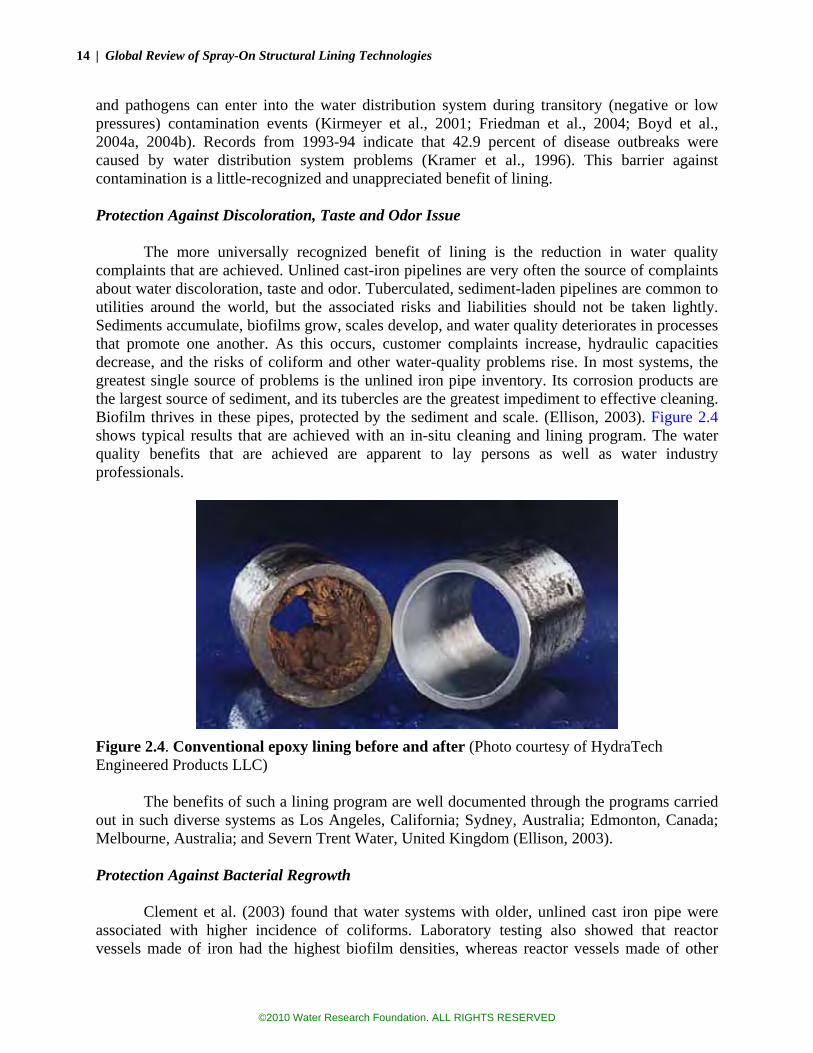
14 | Global Review of Spray-On Structural Lining Technologies
and pathogens can enter into the water distribution system during transitory (negative or low pressures) contamination events (Kirmeyer et al., 2001; Friedman et al., 2004; Boyd et al., 2004a, 2004b). Records from 1993-94 indicate that 42.9 percent of disease outbreaks were caused by water distribution system problems (Kramer et al., 1996). This barrier against contamination is a little-recognized and unappreciated benefit of lining. Protection Against Discoloration, Taste and Odor Issue
The more universally recognized benefit of lining is the reduction in water quality complaints that are achieved. Unlined cast-iron pipelines are very often the source of complaints about water discoloration, taste and odor. Tuberculated, sediment-laden pipelines are common to utilities around the world, but the associated risks and liabilities should not be taken lightly. Sediments accumulate, biofilms grow, scales develop, and water quality deteriorates in processes that promote one another. As this occurs, customer complaints increase, hydraulic capacities decrease, and the risks of coliform and other water-quality problems rise. In most systems, the greatest single source of problems is the unlined iron pipe inventory. Its corrosion products are the largest source of sediment, and its tubercles are the greatest impediment to effective cleaning. Biofilm thrives in these pipes, protected by the sediment and scale. (Ellison, 2003). Figure 2.4 shows typical results that are achieved with an in-situ cleaning and lining program. The water quality benefits that are achieved are apparent to lay persons as well as water industry professionals.
Figure 2.4. Conventional epoxy lining before and after (Photo courtesy of HydraTech Engineered Products LLC)
The benefits of such a lining program are well documented through the programs carried
out in such diverse systems as Los Angeles, California; Sydney, Australia; Edmonton, Canada; Melbourne, Australia; and Severn Trent Water, United Kingdom (Ellison, 2003). Protection Against Bacterial Regrowth
Clement et al. (2003) found that water systems with older, unlined cast iron pipe were associated with higher incidence of coliforms. Laboratory testing also showed that reactor vessels made of iron had the highest biofilm densities, whereas reactor vessels made of other
©2010 Water Research Foundation. ALL RIGHTS RESERVED

Chapter 2: Background, History and Current Practice | 15
pipeline materials (PVC, epoxy, or cement mortar) showed no particular propensity to support biofilms. It follows, then, that the lining of unlined cast iron pipelines provides protection against bacterial regrowth. Other Problems
Cleaning and lining has sometimes been used in asbestos cement pipelines, and other
cementitious pipelines, to prevent the leaching of materials, and to arrest corrosion of the concrete matrix. The Sandwich Water District, (Massachusetts, U.S.) used a rapid-setting polymer to stop the leaching of tetrachloroethylene (PCE) from the vinyl lining of AC pipes (Gove, Oram and Mahoney, 2003). Hydraulic Improvements
Encrustation in old water mains will translate into reduced cross-sectional area and
increased turbulence; hence, a decrease in hydraulic capacity of a pipeline. Lamont (1981) reported 70 percent reduction in hydraulic capacity of a cast iron water main after only 30 years of service. Figure 2.5 shows an extreme case of tuberculation in an iron water main, where the loss of hydraulic capacity is estimated to easily exceed 90 percent. In this case, the pipeline had been installed in 1926 in the City of Los Angeles, on a dead-end street, providing service to five homes. When this section of pipeline was removed in 2006 (for AwwaRF Project 2872), the encrustation was so dense an index finger could not be fully inserted into the 4-inch (100 mm pipe).
There are many methods of cleaning pipelines, but to remove such tuberculation, either pigging or mechanically cleaning is generally needed. The experience of several utilities is that cleaning by itself can lead to more problems than its worth. By exposing bare metal to water, corrosion activity can increase, leading to more water quality issues than before (Ellison, 2003). Even companies that only provide cleaning services caution against cleaning unlined cast-iron or steel pipelines to bare metal, unless lining is applied afterwards, otherwise water quality complaints may increase.
©2010 Water Research Foundation. ALL RIGHTS RESERVED
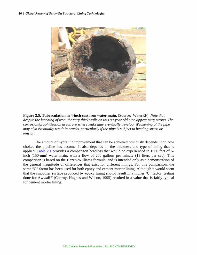
16 | Global Review of Spray-On Structural Lining Technologies
Figure 2.5. Tuberculation in 4-inch cast iron water main. (Source: WaterRF) Note that despite the leaching of iron, the very thick walls on this 80-year old pipe appear very strong. The corrosion/graphitization areas are where leaks may eventually develop. Weakening of the pipe may also eventually result in cracks, particularly if the pipe is subject to bending stress or tension.
The amount of hydraulic improvement that can be achieved obviously depends upon how
choked the pipeline has become. It also depends on the thickness and type of lining that is applied. Table 2.1 provides a comparison headloss that would be experienced in 1000 feet of 6-inch (150-mm) water main, with a flow of 200 gallons per minute (13 liters per sec). This comparison is based on the Hazen-Williams formula, and is intended only as a demonstration of the general magnitude of differences that exist for different linings. For this comparison, the same “C” factor has been used for both epoxy and cement mortar lining. Although it would seem that the smoother surface produced by epoxy lining should result in a higher ‘C” factor, testing done for AwwaRF (Conroy, Hughes and Wilson, 1995) resulted in a value that is fairly typical for cement mortar lining.
©2010 Water Research Foundation. ALL RIGHTS RESERVED

Chapter 2: Background, History and Current Practice | 17
Table 2.1 Headloss Comparisons for Different Lining Thicknesses
[Based on flow of 200 gpm (12 liters/sec) and 1000 feet (305 m) of pipe]
Lining Type Nominal
Size Pipe O.D.
Wall Thickness
Lining Thickness
Effective I.D. Headloss
Cement Mortar – 3/16” (5 mm)
6 inch (150 mm)
6.9 inch (175 mm)
0.34 inch (8.6 mm)
0.19 inch (5 mm)
5.85 inch (149 mm)
5.0 feet (1.5 m)
Epoxy – 1 mm 6 inch
(150 mm) 6.9 inch
(175 mm) 0.34 inch (8.6 mm)
0.04 inch (1 mm)
6.14 inch (156 mm)
3.9 feet (1.2 m)
Epoxy – 3 mm 6 inch
(150 mm) 6.9 inch
(175 mm) 0.34 inch (8.6 mm)
0.12 inch (3 mm)
5.98 inch (152 mm)
4.4 feet (1.3 m)
Epoxy – 5 mm 6 inch
(150 mm) 6.9 inch
(175 mm) 0.34 inch (8.6 mm)
0.20 inch (5 mm)
5.83 inch (148 mm)
5.0 feet (1.5 m)
This table shows that seemingly small variations in the thickness of the lining can have a
significant effect on headloss within a relatively small diameter main. This significance would no doubt be considerably less in larger pipes, but so also would the structural value of the lining, unless applied much thicker. Water Main Rehabilitation Market
Cleaning and lining requires expensive specialty equipment that is generally custom-made. As a result, there are only about a dozen contractors who currently provide this work in the United States. In the U.S., the current market for water main rehabilitation is estimated at $100 to $150 million per year. This estimate was provided by one of the major specialty contractors who performs both cement mortar and polymer lining. The market size is hard to track, because not all work is publicly bid; some work is privately negotiated. Approximately 90 percent of this market is traditional cement mortar lining and 10 percent is epoxy lining. Polyurethane systems have been used as well, but have not yet gained a firm footing in the U.S.
This figure would equate to approximately 350 to 400 miles of pipe being cleaned and lined each year. The market figure reflects overall contract costs, including bypass piping, paving, and appurtenances. It is very common for a utility to replace main line valves, hydrants, services, air/vacuum valves, and blow-offs in conjunction with a main lining project. The cost of these replacements is also included in the estimate provided above.
Compared to the $183 billion infrastructure backlog estimated by the U.S. EPA, this volume of activity is very small indeed. At the current rate, it would take about 400 years to rehabilitate half the pipe in the backlog. However, if a utility is determined to get ahead of the curve, work can be ramped up significantly. The City of Los Angeles, for instance, spent $39 million in just one year (1998), rehabilitating 150 miles of water main. This figure, which has not been adjusted for inflation, shows how truly modest the current activity level is in most other cities. Using a concerted effort for more than a decade, the City of LA eventually lined virtually its whole unlined pipe inventory. Pipe which was not lined was either replaced or scheduled to be replaced.
©2010 Water Research Foundation. ALL RIGHTS RESERVED

18 | Global Review of Spray-On Structural Lining Technologies
CEMENT-MORTAR LINING HISTORY AND PROPERTIES CML History
According to AWWA Standard C602, the use of cement mortar for protective lining of pipelines was first reported in 1836, and by 1850, cement mortar lined pipe was first sold. As earlier described, however, the use of factory lined cement mortar lining did not really take hold within most water systems until about 1940. Thus any cast-iron and steel pipe that was installed prior to 1940 in the United States was likely unlined, or lined with an asphaltic or bitumastic coating that typically did not last very long.
The rehabilitation of water pipelines arguably began in 1905 with the hand-application of cement mortar to the inside of large pipelines. A field trial involving cleaning and mortar lining of a 72-inch (1.8 M) main was conducted in 1933 in New Jersey, with favorable results. The in-situ spray application of cement mortar lining (CML) ensued, but work was limited to larger pipelines (24-inches or 600 mm and larger) which allowed for a man to ride a lining machine. In the 1950s remotely controlled sprayers were developed, allowing for the lining of small pipelines. CML rehabilitation is now well established and accepted in the industry, with millions of miles of pipelines having been lined to date worldwide.
Because of this long history, many cities with large cast-iron pipe inventories have completed the cement mortar lining programs—meaning that virtually no unlined iron or steel water mains or transmission mains remain in their systems. Among these cities are: Los Angeles, California, Sydney, Australia, and Melbourne, Australia. There are also many smaller towns and suburbs, where the systems are relatively young, and unlined cast-iron pipelines likewise don’t exist. However, despite this long history, in the older areas of many large cities and towns, unlined cast-iron pipelines are still prevalent. In a 2003 survey, 25 percent of large utilities and 21 percent of small utilities in the United States reported that unlined cast iron or steel mains were a major component of their systems (Ellison, 2003). Structural Limitations
The chief structural limitation of cement mortar is its inherent lack of reliable tensile
strength. Because it shrinks as it cures, cement mortar develops cracks. The cracks may be visible (macro) or invisible (micro), but where they occur, the tensile strength is zero or close to it. Even without cracks, the tensile strength of concrete is very low, on the order of 500 psi for high-quality mortar. This compares to about 50,000 psi for ductile iron or steel. As a result even a thin steel or cast-iron pipeline has much more hoop or bending strength than a very thick mortar lining. Cement mortar also has a fairly low strain limit (0.0002) in tension, which manifests as cracks when a pipeline is bent or strained through pressurization. Fortunately, cement mortar also has the ability to self-seal, through the precipitation of mineral deposits (Douglas and Merrill, 1991).
The cracks in the mortar allow water to seep through the lining. This is generally not a problem as far as corrosion protection is concerned—because the water that seeps through becomes highly alkaline and non-corrosive—but such seepage negates the structural value of the lining, when equal pressures exist on both sides. In spite of these inherent limitations, field crews have reported seeing large rust holes in old water mains that were not leaking, because mortar was holding back the water pressure.
©2010 Water Research Foundation. ALL RIGHTS RESERVED

Chapter 2: Background, History and Current Practice | 19
Fiber Reinforcement It should be noted that this inherent lack of tensile strength is not necessarily a fatal flaw.
Many methods have been developed to impregnate the mortar mix with different types of fibers, which can provide the tensile strength that is lacking in normal cement mortar. In fact, the millions of miles of asbestos-cement pipe installed in the United States and all around the world are examples of how this has been done quite effectively. By most measures, this material appears to have performed well. One key for improving the structural value of cement mortar is thus finding an appropriate type of fiber reinforcement, recognizing that health concerns regarding asbestos make it a poor candidate for mortar reinforcement today.
In his experimental study, Luk (2001) studied lining of water mains using steel fiber reinforced mortar lining. Although, for his experiments, the lining was not spray-on applied (rather it was pulled through short pipe segments by a trowel) it is noteworthy in that compressive strength increased by 41.4 percent through the use of stainless steel fibers (10 mm long, 1 mm in diameter). Unfortunately, no data were provided for tensile stress increase, which is a more relevant issue when it comes to structural lining of water mains.
Polypropylene fibers are commonly used to reinforce concrete. Such fibers generally are not considered structural, but are added to the concrete mix to improve its tensile capacity and thus reduce the cracking. Because they do not readily corrode, the fibers are more aesthetically acceptable than steel fibers that leave rust staining on the concrete (steel fibers used in concrete are typically not stainless). Reportedly, testing has been conducted using polypropylene fibers to reinforce cement mortar lining, but study reports could not be found. It would be expected that such fiber reinforcement would enhance the structural properties of the mortar, but that the structural properties would still be modest, at best. Hole Spanning
Despite all these structural limitations, few doubt that cement mortar lining plugs holes in
pipelines. In fact, one of the banes of a lining superintendent is keeping the service taps from plugging. The spanning of holes in the walls of pipes has also been observed in the field, where the mortar is visible from the outside of a pipeline, yet the pipeline is not leaking.
The maximum size of hole that mortar can plug depends on the pressure in the pipeline, the quality of the mortar, and thickness of the lining. The sizes of holes that mortar can span can be estimated based on the structural calculations using concrete design principles. For a small hole, punching shear resistance would likely be the limiting factor, and for a larger hole, bending stress would be the limiting factor. Applying these principles, calculations show that a 3/16-inch (4.6 mm) lining should be capable of spanning a hole as large as 0.8 inches (20 mm) when resisting 80 psi of pressure, and 1 inch (25 mm), when resisting 50 psi of pressure. Per AWWA Standard C602, 3/16-inch linings would be used in old cast iron pipelines up to 10 inches in diameter. The thicker linings needed for steel and larger cast iron pipelines will be able to bridge larger holes, or withstand higher pressures.4 Figure 2.6 shows a hole in the exterior of a 36-inch (900 mm) riveted steel trunkline pipe, reported to be 1.5 inches (40 mm). At the time the photo was taken, the cement mortar lining was holding back approximately 80 psi of pressure.
4 No safety factors are included in these calculations. A hole that is marginally larger, or pressure that is marginally higher would be expected to cause the lining to break through the hole.
©2010 Water Research Foundation. ALL RIGHTS RESERVED

20 | Global Review of Spray-On Structural Lining Technologies
Figure 2.6. Exposed Cement Mortar Lining in 36-inch riveted steel pipeline. (Photo courtesy of Michael E. Grahek)
In a very early study of the structural properties of cement mortar lining, the City of
Detroit, Department of Water Supply, performed a pressure test on a pipe with various sized holes and various thicknesses of lining. Hole diameters ranged from 1 inch (25 mm) to 6-inch (150 mm) and lining thicknesses ranged from 0.25 inch (6 mm) to 1 inch (25 mm). Although the 48-inch pipe specimen was set up to test various sized holes and lining thicknesses, the test was stopped when the first failure occurred. That failure involved a 0.5-inch (12 mm) thick cement mortar lining spanning a 6-inch (150 mm) hole. This had been considered the critical hole; although thinner lining sections also existed, they covered holes 2.5 inches (63 mm) or smaller. During the test of this critical hole, cracks were noted in the mortar at the hole when the test pressure reached 210 psi; 15 radial cracks were noted. At 268 psi the lining “began to fail”, and just before failure, an amazing pressure of 305 psi was observed on the gauge (Detroit, 1940).
This ability to plug holes and thereby stop leaks has been verified through the results of cement mortar lining programs. On a major pipeline in Los Angeles, for instance, 220 leaks were recorded in the pipeline’s first 58 years, but only two in the 35 years since it was lined (Ellison, 2001).
However, this ability to span holes is not always been viewed favorably. If a small hole in the steel or cast iron must become a big hole before failure occurs, then when the failure ultimately occurs, it happens with greater consequences. A series of small leaks is avoided, but possibly at the expense of a larger leak or even pipe break, when the defect in the host pipe (assumed to be exterior corrosion) grows to sufficient size. Corrosion of Cement Mortar Lining
In areas where water is extremely soft and poorly buffered,5 cement-mortar lining can
deteriorate—particularly linings that are applied in situ, where asphaltic seal coats are not used. This deterioration is caused by the leaching of lime from the cement mortar matrix. This leaching process has been known to cause water quality problems (excessively high pH) for weeks or months following lining, particularly in dead-end pipelines with little flow. Douglas and Merrill
5 Generally, if alkalinity is less than 55 mg/L as CaCO3, then in-situ lining with cement mortar should not be used.
©2010 Water Research Foundation. ALL RIGHTS RESERVED

Chapter 2: Background, History and Current Practice | 21
(1991) found that about one quarter of utilities surveyed who had performed in-situ cement mortar lining had experienced minor to significant water quality problems.
The leaching of lime also results in softening of the cement mortar and loss of adhesion. Over an extended period of time, lining deterioration may be severe enough to cause the lining to fail, although this is not common. Douglas and Merrill found that even the soft, weakened linings were generally effective in preventing corrosion and tuberculation, and had no detectable effect on pipe roughness. Bypass Piping Systems Required
AWWA Standard C602 requires the curing of cement mortar lining for at least 24 hours
before the pipeline is pressurized. This is to prevent excessive strain and cracking of the green mortar. And though the lining process is fairly clean, it is not inherently sanitary. The aggregate and tools used in the lining process could be a source of contamination, in addition to whatever biofilm contamination remains in the pipe after the tuberculation is removed. Disinfection and bacterial testing are therefore both recommended and required, before a cement mortar lined pipeline is placed back in service. Bypass piping systems are therefore needed for several days before the main is placed back into service. SPRAY-ON POLYMER LININGS – HISTORY AND PROPERTIES
Because of the water quality deterioration that occurred in some systems when cement
mortar lining was used, some utilities began using epoxy lining in the late 1970s and early 1980s. Use of epoxy was officially approved in 1985 in the U.K. By 1995, a study by WaterRF (Conroy et al., 1995) found that epoxy lining was very well established in the United Kingdom, Japan, Sweden and Germany, but at that time, it was still considered new and innovative in the U.S. A U.K. standard for epoxy lining of mains was first adopted in 1989. At this time, lining with epoxy and other polymers has completely replaced cement mortar lining in Britain.
By contrast, polymer lining in the United States has been rather slow to catch on. The ANSI/AWWA Standard C620-07 for in-situ applied epoxy lining only gained approval in 2008, nearly 20 years later than in the U.K. However, despite this lack of a standard, epoxy lining may represent about 10 percent of the lining that occurs here.6 As in the U.K., the use of epoxy lining in the U.S. may be prompted largely by water quality issues with cement mortar linings.
In more recent years, polyurethane lining has gained broad acceptance in the U.K., as well as a polymer hybrid of epoxy and polyurea. This acceptance has been attributed to a faster cure time. The linings that are being used set within minutes and are ready for water contact within two hours. These faster cure times have allowed the pioneering of same-day return to service, eliminating the need for bypass piping systems.
This notion of returning the relined water main back to service within a day is based on the following:
•• Fast-cure times. As discussed later in this report, a fast cure allows for completion of
work, completion of inspection, and contact with water, without risk of leaching chemicals from the resins or hardeners.
6 Based on an e-mail exchange with managers at Heitkamp, a U.S. pipe lining company that provides cement mortar lining, epoxy lining, and polyurethane lining.
©2010 Water Research Foundation. ALL RIGHTS RESERVED

22 | Global Review of Spray-On Structural Lining Technologies
•• Sanitary materials. The raw lining materials are sterile and generally inhospitable to harmful bacteria.
•• Sanitary practices. The lining crews employ practices similar to those observed by break repair crews in making final connections, such that the risk of contamination is minimized. These practices may include the use of high concentrations of disinfectant.
•• Proven Results. Although “boil-water” notices are generally distributed to the area affected by the lining project pending the results from bacteriological tests, at least one U.K. utility no longer distributes such notices, pointing to a spotless record of no positive tests that have been confirmed.7
In the U.S., this faster cure and quick return to service provided by polyurethane and
polyurea has not yet caught hold. The company that first applied the method here reports that no polyurethane lining was done in 2008. This lack of acceptance in the U.S. could be attributed to many factors, including the relatively low amount of pipeline rehabilitation that is performed here, a general lack of knowledge regarding the processes and materials that are available, and a very different regulatory structure, wherein many different health agencies would need to be convinced before the practice became widespread. It’s noteworthy that fast curing polymer lining is being applied in Canada, where the regulatory environment is not as splintered.
Compared to cement mortar lining, polymer linings have appreciable tensile and bending strength, without the need for reinforcement. This has spurred the notion that such linings have the potential to significantly reinforce or strengthen water mains. The structural properties and potentials of these linings are discussed in detail in the next chapter. EPOXY
Epoxy is a thermosetting (i.e., the process is irreversible once it cures) epoxide polymer
(Figure 2.7). The most common type of epoxy used in pipeline coating/lining is fusion-bonded-epoxy, which is formed by reacting bisphenol and epichlorohydrin derivatives under elevated temperatures (they are solid powders at room temperature). These derivatives of bisphenol and epichlorohydrin vary in their composition and molecular weight, which affects the physical and mechanical properties of the epoxy formed. Another factor that influences the properties of epoxy is the curing agent and hardener used along with bisphenol and epichlorohydrin. Examples of curing agents include dicyandiamide, aromatic amines, and aliphatic diamines. Consequently, epoxies with different physical and mechanical properties are used in various industries in addition to pipeline coating and lining. These industries include electrical systems and electronics, and aerospace applications.
7 Although a few positive tests have occurred, each was ultimately determined to be the result of sample contamination.
©2010 Water Research Foundation. ALL RIGHTS RESERVED

Chapter 2: Background, History and Current Practice | 23
Figure 2.7. Molecular structure of epoxy.
Like cement mortar, epoxy linings are generally considered to be “non-structural”. They are typically used to improve system hydraulics, prevent water quality problems at the customer’s tap, and as a means of extending the life of the pipelines by reducing internal corrosion. Generally, they are applied thinly and add little structural strength to the host pipe (Figure 2.8). The standard thickness is 1 mm (0.04 inches), which is too thin to provide significant shear or tensile value.
Figure 2.8. Epoxy spinner-head being inserted into a deteriorated pipe (Source: WRc Group, UK). POLYURETHANE AND POLYUREA
Polyurethane and polyurea have been gaining attention of late as a water pipelining
material, particularly in the United Kingdom, where they are quickly supplanting both epoxy and cement mortar. The primary advantage is a rapid cure time, which has enabled same day return-to-service for rehabilitated water mains, thus avoiding the need for bypass piping systems (Rockaway and Ball, 2007).
Polyurethane is formed by reaction (or addition) of an isocyanate (-N=C=O) group with a hydroxyl (-OH) group or a polyol (Figure 2.9). This reaction is triggered by catalysts. Other typical components of the polyurethanes include cross linkers, surfactants, blowing agents, pigments, and fillers.
Polyols are formed in different ways, such as by a base-catalyzed addition of propylene oxide (PO) and ethylene oxide (EO) onto a hydroxyl or amine containing initiator glycol or dipropylene glycol. Polyols extended with PO or EO are polyether polyols, and the choice of initiator, extender, and molecular weight of the polyol significantly affect the physical and mechanical properties of the polyurethane formed.
©2010 Water Research Foundation. ALL RIGHTS RESERVED

24 | Global Review of Spray-On Structural Lining Technologies
Although, polyols are the main strength parameter, the type of isocyanate group also affects the physical and mechanical properties of the polyurethane. Accordingly, the physical and mechanical properties of polyurethanes vary considerably, and different types of polyurethanes are used in numerous industries, in addition to coating and lining pipelines. These industries include other types of building and construction, transportation, furniture and bedding, appliances, packaging, textile fibers and apparel, machinery and foundry, electronics and footwear.
O
n OCN R NCO n HO R' OH O R' C N R N C- - + - - ( - - - - - - )n
O
H H
Diisocyanate Polyol Polyurethane
O-
Figure 2.9. Polyurethane production by poly addition of diisocyanate and polyol. (Source: Shiwei William Guan, 2003.)
One of the lining materials that is commonly described as a “polyurethane” in the water industry, is more a polyurea (or more precisely as a hybrid of polyurea and epoxy). This high-build hybrid polymer product has gained broad usage in the U.K. and is being tried in Canada, and Australia. (More information about its properties is found in Chapter 3.)
Polyurea forms in an analogous way to polyurethane, except that for the polymerization of polyurea, an isocyanate group occurs with polyamines rather than polyols. The polymerization of isocyanates with polyamines result in the urea linkage. Generally, polyureas appear to have better elongation properties than polyurethanes; on the other hand polyurethanes provide more stiffness.
Short curing time (both polymers gain their physical properties within minutes after application) is the primary advantage to both polymers. To the authors’ knowledge, polyurea has not been used in the USA to rehabilitate water mains. Its application is very common in coating/lining wastewater treatment plant process tanks, wet wells, and sanitary sewer manholes. Some difficulties have been reported with polyurea, with initial set-up sometimes occurring before the material reaches the surface of the host material. The result can be poor adhesion and blistering, which often require removal and replacement. The physical and mechanical properties of polyurethanes and polyureas are highly dependant on the polymerization process, fillers, antioxidants, additives, etc. Although polyurethanes generally have higher stiffness, independent research indicates close mechanical properties for both polymers at low strains (Sarva et al., 2007). THE PROCESS OF CLEANING AND LINING
Cement mortar lining and polymer lining processes are similar, although with notable
exceptions. A brief description of these processes follows. For more detailed information, the AWWA M28 Manual can be consulted.
Step 1 Bypass Piping System. A bypass piping system is designed and installed
using time-tested guidelines (hydraulic analysis is generally not
©2010 Water Research Foundation. ALL RIGHTS RESERVED

Chapter 2: Background, History and Current Practice | 25
employed.) Figure 2.10 shows a typical bypass piping system, with 2-inch mains along both sides of the street, a hose feed to the meter box, and rubber protection ramps at the driveway. The system must be flushed, tested, disinfected, and checked for bacteria before being placed into service. The bypass system must remain in service for the duration of the lining process and until the relined main has been cured, tested and is ready to return to service. As noted elsewhere in this report, some utilities in Canada and the U.K. avoid bypass systems by: (1) using a fast-cure polymer system, (2) returning the main to service within a day, and (3) sampling for bacteria and (4) possibly issuing a boil-water notice to customers until the bacterial testing results are in hand.8
Figure 2.10. Bypass piping system in Los Angeles. (Photo courtesy of Michael E. Grahek)
Step 2 Pipeline Access. The main is accessed by sawcutting the pavement,
excavating pits, and cutting out a section of pipeline. This is preferably done at a valve, bend, fitting, or other location where an excavation is needed anyway.9 These access pits are typically laid out and excavated while the bypass system is being installed and tested. When not being worked on, the pits are covered with traffic plates. Figure 2.11 shows one of these access pits, with the traffic plate cover placed at the side.
Step 3 Pipeline Cleaning. One of two mechanical cleaning methods is used to
break-up tubercles and remove them from the pipe. Drag scraping 8 Because they are confident in the processes used and have hundreds of tests to back their confidence, U.K. utilities do not generally issue boil-water notices on most lining projects. 9 For most water main rehabilitation methods, it is preferred to remove valves and bends and use these excavations for access to the pipeline. It is sometimes possible to navigate the equipment through the valves and bends, but this would be an exception to standard practice.
©2010 Water Research Foundation. ALL RIGHTS RESERVED

26 | Global Review of Spray-On Structural Lining Technologies
(Figure 2.12) is the most common method in the U.S., whereas rackfeed power boring (Figure 2.13) is also used, particularly in Europe. Rackfeed power boring has some advantages where the mains and service taps are smaller. Mechanical cleaning is followed by other methods to remove debris and water, including water jetting, squeegees and swabs. Frequently, the pipeline is then inspected using closed-circuit television (CCTV). CCTV is generally recommended for polymer lining, where the degree of cleanliness is more critical to lining success. AWWA Standard C620 mandates CCTV for epoxy lining.
Figure 2.11. Access pit for cleaning pipe. (Photo courtesy of Michael E. Grahek)
Figure 2.12. Drag scraper. (Photo courtesy of Michael E. Grahek)
©2010 Water Research Foundation. ALL RIGHTS RESERVED
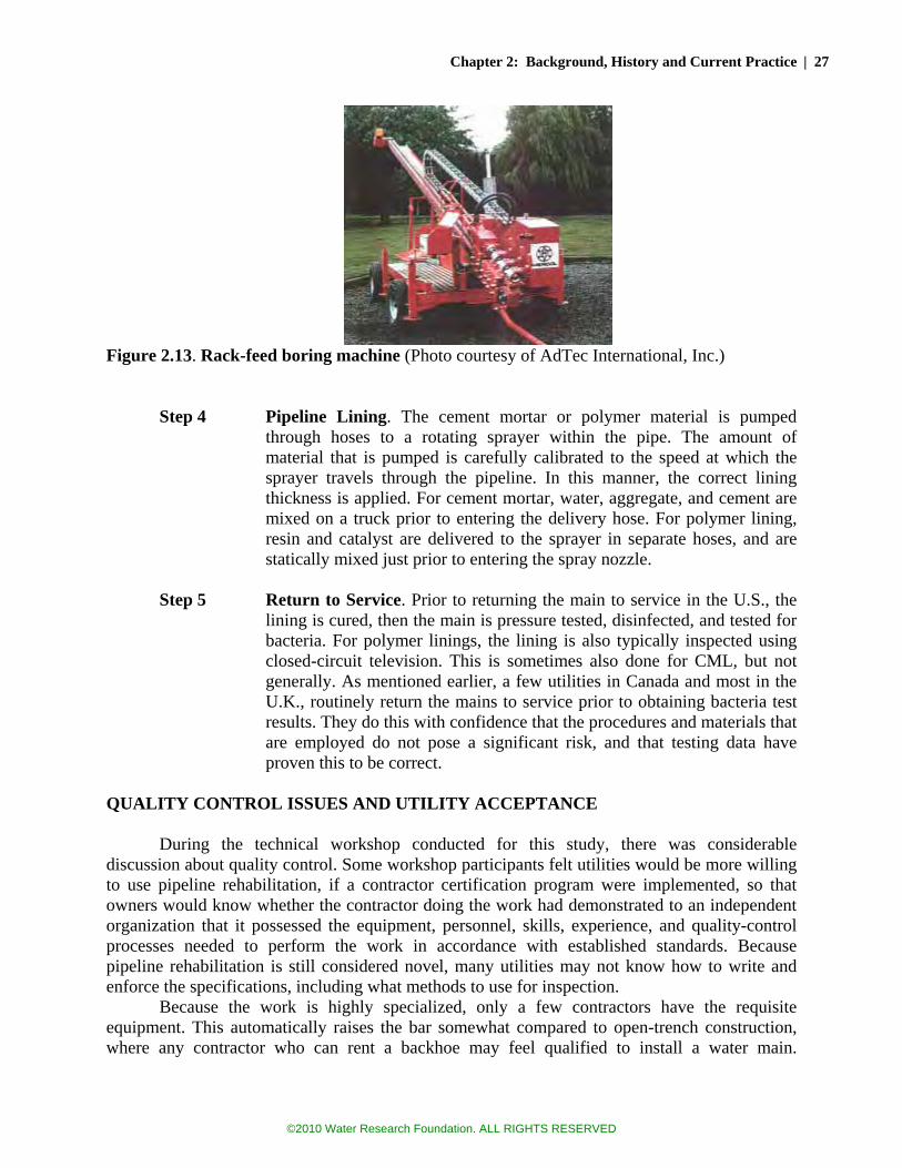
Chapter 2: Background, History and Current Practice | 27
Figure 2.13. Rack-feed boring machine (Photo courtesy of AdTec International, Inc.)
Step 4 Pipeline Lining. The cement mortar or polymer material is pumped
through hoses to a rotating sprayer within the pipe. The amount of material that is pumped is carefully calibrated to the speed at which the sprayer travels through the pipeline. In this manner, the correct lining thickness is applied. For cement mortar, water, aggregate, and cement are mixed on a truck prior to entering the delivery hose. For polymer lining, resin and catalyst are delivered to the sprayer in separate hoses, and are statically mixed just prior to entering the spray nozzle.
Step 5 Return to Service. Prior to returning the main to service in the U.S., the
lining is cured, then the main is pressure tested, disinfected, and tested for bacteria. For polymer linings, the lining is also typically inspected using closed-circuit television. This is sometimes also done for CML, but not generally. As mentioned earlier, a few utilities in Canada and most in the U.K., routinely return the mains to service prior to obtaining bacteria test results. They do this with confidence that the procedures and materials that are employed do not pose a significant risk, and that testing data have proven this to be correct.
QUALITY CONTROL ISSUES AND UTILITY ACCEPTANCE
During the technical workshop conducted for this study, there was considerable
discussion about quality control. Some workshop participants felt utilities would be more willing to use pipeline rehabilitation, if a contractor certification program were implemented, so that owners would know whether the contractor doing the work had demonstrated to an independent organization that it possessed the equipment, personnel, skills, experience, and quality-control processes needed to perform the work in accordance with established standards. Because pipeline rehabilitation is still considered novel, many utilities may not know how to write and enforce the specifications, including what methods to use for inspection.
Because the work is highly specialized, only a few contractors have the requisite equipment. This automatically raises the bar somewhat compared to open-trench construction, where any contractor who can rent a backhoe may feel qualified to install a water main.
©2010 Water Research Foundation. ALL RIGHTS RESERVED

28 | Global Review of Spray-On Structural Lining Technologies
However, even with this higher bar, contractors with virtually no relevant experience have been known to try water main rehabilitation, with rather poor results.10
In an earlier WaterRF study, Conroy et al. (1995) investigated epoxy linings as a new pipeline rehabilitation method in North America. Among the findings of this study was a utility survey asking if they would consider epoxy linings as a new rehabilitation method. The respondents in general, listed three standards the new product should comply with before they would consider using it, namely National Sanitation Foundation (NSF 61), American National Standards Institute (ANSI), and Underwriters Laboratories (UL). Forty-seven percent of the respondents indicated they would consider a demonstration if the product is NSF 61 certified, whereas 21 percent said they would require ANSI approval in addition to NSF 61 or ANSI only.11 Two of the 19 utilities wanted compliance with UL standards before they would consider a demonstration of the material. It appears that most utilities in general are focused on the effects of new spray-on linings on water quality more so than QA/QC procedures during application. However, research studies or field applications to date indicate that it is not uncommon to experience a failure while applying spray-on linings in the field.
Deb et al. (2006) listed the following as the common application problems for spray-on epoxy:
• Lining Over Debris. Lining voids and blisters sometimes occurred when miscellaneous debris was not effectively cleared from the host pipe prior to lining.
• Blistering. Formation of blisters (bubbles) was attributed to the graphitization of the host pipe (if made of iron). Although, for most cases, blistering was indicated as a trivial issue that would not cause a failure of the lining.
• Uncured Lining. Operational problems of the lining rig may affect the mix ratio of the components and result in incomplete curing of the spray-on lining. This is probably the most serious problem that can arise in spray-on lining. If unresolved, it can result in chemicals entering the water and potential health consequences.
• Incomplete or Thin Lining. The causes of thin or incomplete lining were listed as malfunction of the lining rig, spinner head, excessive friction between the lining hose and interior of the host pipe as the hose is being winched back through the pipe, or protruding obstacles in the host pipe. A thin lining is an important issue in consideration of structural water main rehabilitation, because strength is directly dependent on the thickness of the lining.
• Ringing or Ridged Lining. If the lining head does not travel smoothly through the pipe, but travels by stops and jerks, the lining will be applied unevenly, and ridges or rings will appear in the finished product. The causes are excessive friction of the hoses within the pipe, snagging of the hose on service taps, bends, and fittings, or malfunction of the winch gear used to pull the hose through the pipe.
• Slump. An accumulation of lining along the invert was attributed to excessive lining sprayed onto the host pipe and overheating of epoxy. This may be a critical obstacle for structural pipeline rehabilitation, since higher than usual thicknesses are sought. It appears that the thicker the lining, the harder it is to form and solidify on the crown of the pipe.
10 This is based on an author’s experience managing the largest pipeline rehabilitation program in the United States. 11 ANSI/NSF 61 is the current testing standard that must be satisfied. Several testing agencies provide ANSI/NSF 61 certification testing, including: NSF, UL, WQA, and IAPMO.
©2010 Water Research Foundation. ALL RIGHTS RESERVED

Chapter 2: Background, History and Current Practice | 29
• Water Damage. This is a result of standing water in the pipeline that is not drained out prior to lining. A “dry” pipe is not required for epoxy linings, but standing water is never allowed.
• Holidays. These are pinholes or discontinuities in the lining due to application defects, often resulting from entrained air in the lining.
Experts who have been involved in polymer lining for several years have indicated that
most problems stem from poor pipeline cleaning. An experienced crew with good equipment will generally have the lining process down correctly, but may have incentive to short-change the cleaning process. Video inspection by an experienced contractor and independent inspector is generally effective in minimizing such problems. These common problems experienced in epoxy lining will generally apply equally to other spray-on materials such as polyurethane and polyurea, but because set-up time for these linings is very short, surface preparation for these lining is more critical. The shorter set-up time provides a much shorter window for the coating to “wet” the surface and achieve adhesion before curing. These fast-setting materials are generally less tolerant of moisture, so a more thorough job of drying the pipe is required, although this has been overcome with clever formulations.
Several experts have expressed a concern about a “shadow” effect wherein protruding services taps may block the spray, preventing full coverage of the pipeline surface. Other concerns include possible lining discontinuities at the joints. Excessive shrinkage of the lining as it cures could also result in detachment, with an associated risk that the liner might fail to protect the pipe and perhaps collapse.
The Case studies found in Chapter 7 briefly touch upon quality issues that have been encountered with polyurethane linings in the U.K. Also, in Chapter 6 are the results of laboratory testing performed on in-situ lined samples taken from various points in a distribution system.
The quality of the finished product is a greater concern if the lining is to be considered structural. Thinning, blistering, holidays, gaps, and voids would all represent structural defects. Deb et al. (2006) focused on thin epoxy lining applications and found that dry film thickness (DFT) of specimens taken from the field varied dramatically, ranging from 0.027 inch (0.7 mm) to 0.134 inch (3 mm). Moreover, the greatest variations occurred where the specified thickness was highest. These results suggest that greater thickness variations may be expected with the increased lining thicknesses needed for structural linings. It should be noted that the epoxy resins that were studied were not formulated for high-build applications and that some slump is permitted by the U.K. Water Operational Guidelines and Code of Standard Practice, provided a minimum thickness of 1 mm (0.4 inch) is achieved at all points. THE LIFE EXPECTANCY OF POLYMER LININGS
The study by Deb et al. (2006) estimated the longevity of epoxy lining within water
mains as 40 to 60 years, for linings installed in accordance with industry standards. The methods they used to arrive at this estimate were:
• Laboratory examination of 17 pipeline segments from 5 utilities with 8 different
lining materials. The samples ranged from 1 to 25 years in age. Tests included: (1) electrical impedance spectroscopy (EIS), (2) dry film thickness, (3) holiday density, and (4) knife adhesion
©2010 Water Research Foundation. ALL RIGHTS RESERVED

30 | Global Review of Spray-On Structural Lining Technologies
• Accelerated tests involving immersion in low-ionic water at elevated temperatures, with reduced lining thickness and intentional holidays. EIS was used to estimate barrier protection.
It should be recognized that this estimate of life expectancy is based on a rather short performance history and a small number of field samples. Moreover, general experience with pipeline corrosion has shown that a vast majority of a pipeline may be well protected from corrosion, but still “fail” due to a small area left vulnerable by a breach, defect or anomaly of some type. So, while the lining may protect most of the underlying metal, holidays, gaps, and other defects may eventually result in leaks and breaks in the pipe. The samples examined by Deb et al. were thinly lined (1 mm) and focused on the durability of the lining in providing corrosion protection. The durability of thicker linings intended to provide structural value would require different considerations, particularly the long-term mechanical properties of the material. OTHER (NON-SPRAY APPLIED) LINING METHODS
Most other methods of water main rehabilitation involve some type of slip lining or
cured-in-place lining. The simplest is a loose slip lining, where a smaller pipe is pulled inside an existing pipe. The chief disadvantage of this method is possible loss of hydraulic capacity. Even if the new pipeline is relatively smooth compared to the old one, a capacity loss of 25 to 50 percent may occur12—but not necessarily. With a small annulus, it is possible to achieve equal or even greater hydraulic capacity. For instance, inserting a 5.6-inch (140 mm) OD DR 21 HDPE pipe inside a 6-inch (150 mm) cast iron pipe could result in a significant flow increase due to the differences in C factors (148 vs. 90).13
There are also several methods of inserting a “tightfitting” slip lining within the host pipe. These result in less loss of capacity, but are more difficult to achieve, and frequently do not result in a lining with full structural capacity14. There are also concerns in both methods about the long-term performance of such linings, if thin-walled linings are utilized (Bakeer et al., 2001). The other common method of water main rehabilitation is use of cured-in-place pipelining (CIPP). This method involves the insertion of a resin impregnated felt or fabric tube within the pipe. Once in place, the tube is pushed outward against the pipe wall, using water or air pressure, and then typically cured by hot water, steam or UV light. The result is a tight-fitting lining within the host pipe, typically designed to resist soil, traffic, and other external pipe loads. CIPP methods were originally developed about 30 years ago in the U.K. (Iseley, 1996) and are most commonly found in wastewater and storm water applications, primarily because the standard
12 For instance, a 12-inch OD pipeline inside a 14-inch ID pipeline results in a 40 percent reduction in cross-sectional area (assuming wall thickness of 0.5 inches). Of course if the host pipe is heavily tuberculated, rehabilitation by cleaning and slip lining could significantly improve the hydraulic capacity of the pipeline, by increasing the effective bore and reducing the roughness. 13 In this example provided by United Utilities, a U.K. water company, the flow increase for a 1 percent headloss was calculated as 2 percent. The pressure rating would be 80 psi (5.4 bar). 14 AwwaRF Projects No. 2629 (Ellison 2001) and 2872 (Ellison et al. 2007) provide detailed descriptions of various methods in which fused HDPE or PVC pipeline strings are inserted within host pipes and made to fit snugly. These methods are currently marketed as “Roll-down”, “Swage Lining”, “Subline”, and “Duraliner”, by the companies that own the patents.
©2010 Water Research Foundation. ALL RIGHTS RESERVED

Chapter 2: Background, History and Current Practice | 31
product, which uses a felt tube, provides little pressure resistance and few advantages over epoxy or cement-mortar lining. However, several of these linings have been developed which utilize fabrics made from polyester, fiberglass, or carbon fiber, and promise considerable pressure resistance.
It is noteworthy that in all cases, the lining methods just described do not adhere to the inner wall of the host pipe. Adherence to the pipe wall can be either an advantage or a disadvantage, depending on how you look at it. The advantage of a lining that adheres to the pipe wall is that the pipe will be easier to tap and to repair; no special connection to the lining is needed. However, the disadvantage is that a lining which adheres to the pipe wall is more likely to tear, if the pipe wall cracks. Structural and Semi-Structural Linings – Definitions
These other methods of lining are all either “structural” or “semi-structural”. “Structural”
methods are those that produce a pipe within a pipe, where the inner pipe is considered capable of resisting all the anticipated loads, including internal pressure and external soil loads. A “semi-structural” method relies on the host pipe for some measure of its support. Perhaps it’s incapable of fully resisting the internal pressure, and only spans across the holes and gaps in the host, or it may be unable to resist external pressures, and could collapse (at least temporarily), if ever depressurized, if not supported by the host pipe.
AWWA Manual M28 further distinguishes linings into four classifications: • Class I Linings. These are non-structural systems, such as traditional CML and
epoxy. • Class II Linings. These are close-fitting semi-structural linings that can span holes
and gaps in the host pipe, but have minimal thickness and require support from the host pipe to prevent collapse during depressurization.
• Class III Linings. These are similar to Class II linings, except they have sufficient thickness to resist buckling from external hydrostatic load or vacuum.
• Class IV Linings. These are fully structural—essentially a pipe within a pipe. Service Reinstatement
Both the CIPP and the slip lining methods have a significant disadvantage compared to
spray-applied linings that is the need to somehow connect service laterals to the linings. To be considered structural or even semi-structural, it is generally necessary to excavate a hole at each service connection, and physically attach the service lateral to the new lining (although in some cases, this reconnection is done remotely using an in-pipe robotic device). Figure 2.14 shows the typical conditions that would exist following a tight-fit slip lining installation, or a CIPP lining.
©2010 Water Research Foundation. ALL RIGHTS RESERVED

32 | Global Review of Spray-On Structural Lining Technologies
Figure 2.14. Tight-fit slip lining or CIPP Lining, prior to service reinstatement (Source: Ellison, 2007)
A recently completed WaterRF study (Ellison et al., 2007) demonstrated that “low-dig”
and “no-dig” service connections were possible for these methods utilizing in-pipe robots, and one rehabilitation contractor is currently marketing a technique wherein an internal tap is made robotically, but the method is still new and far from foolproof. Figures 2.15 and 2.16 show even more difficult conditions that exist following pipe bursting and loose-fit slip lining rehabilitation projects. In these cases, it is very unlikely that a no-dig method of service resinstatement will be developed any time soon. For these methods, after excavations are made at each service connection, the “trenchless” method of rehabilitation may not be very trenchless.
Figures 2.15 and 2.16. Pipe bursting and loose-fit slip lining, prior to service reinstatement (Source: Ellison et al., 2007)
This is an area where spray-on linings offer a major, distinct advantage—little if any work is generally needed to restore the service connection. In fact, where the lining is thin (e.g., epoxy lining), there is nothing to do. The lining does not typically block the corporation tap at all. Where the lining is thicker (e.g., CML), a short blast of air down the lateral dislodges the mortar plugging the lateral, restoring the bore.
Figure 2.17 shows the condition that might be expected to exist following the application of cement mortar linng or very thick polymer lining. Either the lining has not plugged the service opening, or a quick blast of air (or vacuum) on the other end of the service line has displaced any plug that momentarily may have existed. Keeping the service lines from plugging is potentially a
©2010 Water Research Foundation. ALL RIGHTS RESERVED

Chapter 2: Background, History and Current Practice | 33
bigger issue if polymer linings become thicker and shorter cure times are used, but the application of a steady vacuum on the service lines as the lining machine passes should be sufficient to assure that no bridging across the service tap occurs.
It’s noteworthy that the simplicity of the connection is due to the adhesion of the lining to the pipe wall. This adhesion connects the lining to the pipe, which in turn is connected to the lateral. No additional connection is needed.
Figure 2.17. Spray-on structural lining condition – no service reinstatement required (Source: Ellison et al,. 2007) The Advantages (and Disadvantages) of Good Lining Adhesion
The adhesion of the lining to the pipe is both a boon and a bane. It means that the lining
is accomplished very simply, at a low cost. It also means that a new service connection need only connect to the host pipe (not to the lining itself), that a normal pipeline clamp may be used to fix a leak, and that normal compression fittings can be used to connect this lined pipe to another pipe. But good adhesion also means that the lining is dependent on the host pipe. If the host pipe corrodes at the corporation stop, the connection could be lost. Good adhesion also means that the lining is wed to the host pipe. This is very important as far as this study is concerned; if the host pipe cracks, very good adhesion means the lining will tear. The key to saving the lining is that it must detach from the pipeline, when needed, to prevent tearing. The notion of lining detachment is discussed in the next several chapters.
Good adhesion of the lining is important from another perspective—corrosion protection. If leakage of water occurs into the annulus between lining and pipe, not only is the structural value of the system compromised, but also corrosion protection is compromised. Unlike cement mortar, which protects the metal chemically, polymer linings protect the metal by keeping the water away. That protection is lost if the adhesion is lost, an annulus develops, and water enters the annulus area.
©2010 Water Research Foundation. ALL RIGHTS RESERVED

34 | Global Review of Spray-On Structural Lining Technologies
©2010 Water Research Foundation. ALL RIGHTS RESERVED

35
CHAPTER 3 STRUCTURAL PROPERTIES AND POTENTIALS OF POLYMER
LINING In the last chapter, traditional lining methods were discussed, and it was noted that
cement mortar and epoxy linings have usually been considered “non-structural”. It was also noted that, despite this designation, cement mortar does have a recognized ability to sometimes span across small holes and gaps in pipelines. Because cement mortar shrinks upon curing, cracks form and adhesion to the pipeline wall can be lost, particularly at the crown of the pipe. This cracking and detachment mean that the tensile strength in mortar can be nonexistent in portions of the lining. In other words, the structural properties of cement mortar are not reliable. The fact that cement mortar sometimes holds back water is good, but this property is incidental, and should not be considered a reason for lining the pipe. This limitation perhaps could be overcome to some extent by fiber reinforcement, but the resulting mortar-fiber matrix would be still relatively weak in tension. This weakness may be the reason that fiber-reinforced cement mortar has never found acceptance as a lining material.
Polymer linings, on the other hand, have much greater structural potential, and will be the focus of this chapter. Unlike cement mortar lining, polymers in general and epoxies, polyurethanes, and polyureas in particular have appreciable tensile and bending strength, without the need for fiber reinforcement. Flexural strengths range to 14,000 psi—still much lower than for iron or steel, but substantial nonetheless—and reliable—particularly in comparison to cement mortar. This creates the expectation that such linings are better suited as structural or semi-structural linings. In later chapters, the structural capabilities of polymer linings are demonstrated. THE STRUCTURAL PROPERTIES OF POLYMER LININGS
Table 3.1 (following page) shows the reported tensile strengths, flexural strengths, flexural moduli, and adhesive strengths of several products that are currently marketed as linings for water mains or are anticipated to enter the market in the foreseeable future. For comparison purposes, the properties of other plastic pipe and lining materials are also presented. This table is intended to illustrate the general range of values that are available, and is not an endorsement of any particular product. These values come from the manufacturers—most are based on third-party tests—but the accuracy of the values has not been independently verified.
A wide-range of strengths exists, even within a specific class of polymer. The flexural strength of epoxies, for instance, ranges from about 5,000 psi to over 14,000 psi. The differences in strength derive from differences in formulation, as described in the last chapter. These strength differences are generally by design. The lower strength materials are intended to be simple coatings (barriers separating the water from the metal), whereas the higher strength materials are intended to provide structural strength. Higher strength materials are also generally harder, less flexible, and more brittle.
©2010 Water Research Foundation. ALL RIGHTS RESERVED

36 | Global Review of Spray-On Structural Lining Technologies
Table 3.1 Mechanical Properties of Various Polymeric Lining and Pipeline Materials
Lining Type
Tensile Yield
Strength
Ultimate Flexural Strength
Flexural Modulus of Elasticity
Adhesive Strength
A (Epoxy) 48,300 kPa (7,000 psi)
97,000 kPa (14,100 psi)
3,600,000 kPa (521,000 psi)
3,900 kPa (570 psi)
B (Epoxy) 53,100 kPa (7,700 psi)
74,000 kPa (10,688 psi)
5,900,000 kPa (857,000 psi)
>17,200 kPa (2,500 psi)
C (Epoxy) 22,200 kPa (3,225 psi)
38,000 kPa (5,540 psi)
1,181,000 kPa (263,000 psi)
N/A
D (Polyurea hybrid) 14,200 kPa (2,060 psi)
25,000 kPa (3,626 psi)
770,000 kPa (112,000 psi)
10,200 kPa (1,480 psi)
E (Polyurethane) 40,600 kPa (5,900 psi)
66,000 kPa (9,558 psi)
2,838,000 kPa (412,000 psi)
26,000 kPa (3,800 psi)
F (Polyurethane) 62,000 kPa (9,000 psi)
97,000 kPa (14,000 psi)
5,100,000 kPa (735,000 psi)
>17,200 kPa (2,500)
G (Polyurea) 59,000 kPa (8,600 psi)
98,600 kPa (14,300 psi)
2,600,000 kPa (383,000 psi)
10,300 kPa (1,500 psi)
H CIPP N/A 31,000 kPa (4,500 psi)
2,758,000 kPa (400,000 psi)
N/A
I HDPE 21,000 kPa (3,000 psi)
N/A 940,000 kPa (135,000 psi)
N/A
J MDPE 15,900 kPa (2,300 psi)
N/A 700,000 kPa (102,000 psi)
N/A
K PVC 55,200 kPa (8,000 psi)
88,000 kPa (12,800 psi)
3,316,000 (481,000 psi)
N/A
Notes for table: For Linings B and F, the substrate failed before the adhesion Lining A: Flexural strength and pull-off adhesion tests were conducted in accordance with ASTM D790 and ASTM D4541, respectively.
Reported tensile strength may be ultimate, not yield. Adhesion performed on concrete. Lining B: Flexural strength test was conducted in accordance with ASTM D790. Adhesion testing done on steel. Lining C: Standard used for flexural strength test is unclear. Modulus is indicated as Young’s modulus, which could be tensile modulus of
elasticity. Reported tensile strength may be ultimate, not yield. Lining D: Standard used for flexural strength test is unclear. Pull-off adhesion test was conducted in accordance with ASTM D4541, on
sandblasted cast-iron. Without sandblasting, adhesion was 7,600 kPa (1,100 psi) Lining E: Flexural strength test was conducted in accordance with BS EN ISO 178. Adhesion test per ASTM D4541. Lining F: Flexural strength and pull-off adhesion tests (in house) were conducted in accordance with ASTM D790 and ASTM D4541,
respectively. Adhesion performed on concrete. Lining G: Tensile strength per ASTM D412, flexural strength and per ASTM D790, Adhesion on sandblasted steel, per ASTM D4541. Lining H: Properties are typical for standard CIPP. Advanced products designed for pressure systems may have higher values. Pipe I: High density polyethylene. Tensile strength: 26,000 kPa (3,250 psi) Pipe J: Medium density polyethylene (used in Europe). Modulus of elasticity is from Point Group, Inc. Tensile yield based on Brandrup,
Immergut and Gruike, Polymer Handbook. Pipe K: Standard PVC. N/A: Not available or not applicable.
©2010 Water Research Foundation. ALL RIGHTS RESERVED

Chapter 3: Structural Properties and Potentials of Polymer Lining | 37
HOOP STRESS RESISTANCE OF A LINED PIPE
The ability to contain pressure is probably the first characteristic that most people would think of when considering the structural capacity of a pipe or a pipe lining. Sufficient circumferential strength is needed to contain the pressure and keep the pipe from splitting. This is commonly thought of as “hoop” strength or resistance to “hoop” stress.
Table 3.2 shows the thicknesses that would be needed for a polymer lining to be capable of sustaining the hoop stresses produced in distribution mains without any assistance from the host pipe. This table is similar to Table 1.1, except that higher tensile values have been used, reflecting the strength of materials that are anticipated to enter the water main lining market soon. These higher tensile values result in linings that are thinner than shown in Table 1.1. For this table, a smaller factor of safety has also been applied (2 vs. 2.5), reflecting the safety factor used for PVC and HDPE pipe in AWWA Standard C900, C905 and C906.
It should be noted that prior to adoption as a standard, all these values would need further study to establish a hydrostatic design basis (established by long-term pressure tests) and an appropriate design factor (the reciprocal of the safety factor—established by examining slow-crack growth resistance, among other factors).
The purpose of this table is merely to demonstrate possibilities. These values may not be conservative; the values shown in the table for 100,000-hr tensile strength, in particular, is probably an upper limit based on an assumption that these materials would behave similarly to HDPE. This assumption was made because results of long-term testing of these lining materials could not be found. The true value for the 100,000 hour strength may be considerably lower.
Table 3.2
Calculated1 Minimum Lining Thickness Needed for Stand-alone2 Lining (based on high-strength polymeric material)
Thickness required for:
Pipeline Operating Pressure
50 psi (0.3 MPa) 80 psi (0.5 MPa)
6 -inch (150 mm) diameter pipe 0.07 inch (1.8 mm) 0.11 inch (2.8 mm)
8 -inch (200 mm) diameter pipe 0.09 inch (2.3 mm) 0.14 inch (3.6 mm)
12 -inch (300 mm) diameter pipe 0.13 inch (3.3 mm) 0.21 inch (5.3 mm)
16 -inch (400 mm) diameter pipe 0.18 inch (4.6 mm) 0.28 inch (7.1 mm)
Based on:
Short-term tensile strength 9,000 psi (62 MPa)
Assumed 100,000-hr tensile strength 4,500 psi (31 MPa)
Safety factor @ 100,000 hours 2.0
Hydrostatic design stress @ 100,000 hrs 2,250 psi (15.5 MPa)
1 The calculations are based on the standard hoop stress calculation: P = 2St / D, where P = pressure rating, S = hydrostatic design stress, t = wall thickness, and D = inside diameter 2 “Stand-alone” in this case means able to resist hoop stress without assistance of the host pipe.
©2010 Water Research Foundation. ALL RIGHTS RESERVED

38 | Global Review of Spray-On Structural Lining Technologies
The lining thicknesses shown in the above table are all considered feasible. In fact, 3 mm (0.12 inch) thick, high-build linings are currently being applied in the U.K. in many applications. This thickness would appear to be sufficient for a large portion of pipelines in most distributions systems, which are 4, 6, or 8 inches.
Even the thicker linings shown here would not be difficult. Experts familiar with the application of polymer linings have indicated that the technical problems of applying thick linings within small pipes are not insurmountable. In fact, several years ago, a U.S. company demonstrated the application of a 0.3 inch (7 mm) lining within a 6-inch cast-iron main. The demonstration, which occurred in 1999 at an AWWA Pipeline Rehabilitation Workshop in La Mesa, California, was performed by a company that has subsequently gone out of business (presumably for lack of business).
The lining thicknesses shown in Table 3.2 would indeed be considered unusually thick for conventional epoxy lining, which is typically applied at 1 mm (0.04 inch), however single-pass applications of up to 0.25 inches, and multiple-pass applications of 0.5 inches are routinely achieved in the lining of manholes, tunnels, tanks and other structures.3 However, the build up of thick coats is often done with multiple passes in a hand-application process. Each pass achieves a partial set before the next pass occurs, such that the material does not sag excessively. If the material sets too much before the next pass is applied, proper adhesion can be an issue, particularly if the lining cures to a very glossy finish.
With the faster-curing polyurethane or polyurea materials, there is almost no limit to the number of passes that could be applied, if the material will bond to itself. One lining manufacturer indicates their lining is suitable for passage of a closed-circuit television camera, within 10 minutes of application. This would imply that a second pass of the lining machine might also occur within a few minutes. With this short set-up time, perhaps 2 or 3 layers could be applied every hour, if desired.
However, there are technical issues to be solved before the application of thicker linings becomes routine in pipes where hand-application is not possible:
•• Material temperature. With very thick materials, the material can heat excessively as it cures, with deleterious results (shrinkage and cracking).
•• Sagging. If a thick lining takes too long to set up, the material will sag, resulting in non-uniform coating and roughness.
•• Intercoat bonding. If multiple passes are applied, bonding between coats becomes a concern, if the material sets up very quickly and is very glossy.
Both optimists and pessimists can be found regarding whether these technical issues can be readily solved.
The thicknesses shown in Table 3.2 are based on internal pipeline pressures of 50 psi and 80 psi, while providing a normal safety factor of 2.0 at the 100,000-hour design basis4. It should be recognized that the 50 to 80 psi pressures in this table may be exceeded in certain parts of many systems. While 80 psi is the U.S. standard for maximum pressure in building plumbing, utility distribution systems very frequently operate to 150 psi, with portions of some systems 3 One of the epoxy manufacturers reported that they have successfully applied a 0.25-inch (10 mm) lining in one pass within a 15-inch diameter pipeline, in a demonstration run. Reportedly, this was done with good uniformity and without sagging. Copies of a report attesting to this demonstration were not available at the time of publication. 4 The strength of all plastic linings is time-dependent. The 100,000 hour strength is the convention used for PVC and HDPE materials, per AWWA standards.
©2010 Water Research Foundation. ALL RIGHTS RESERVED
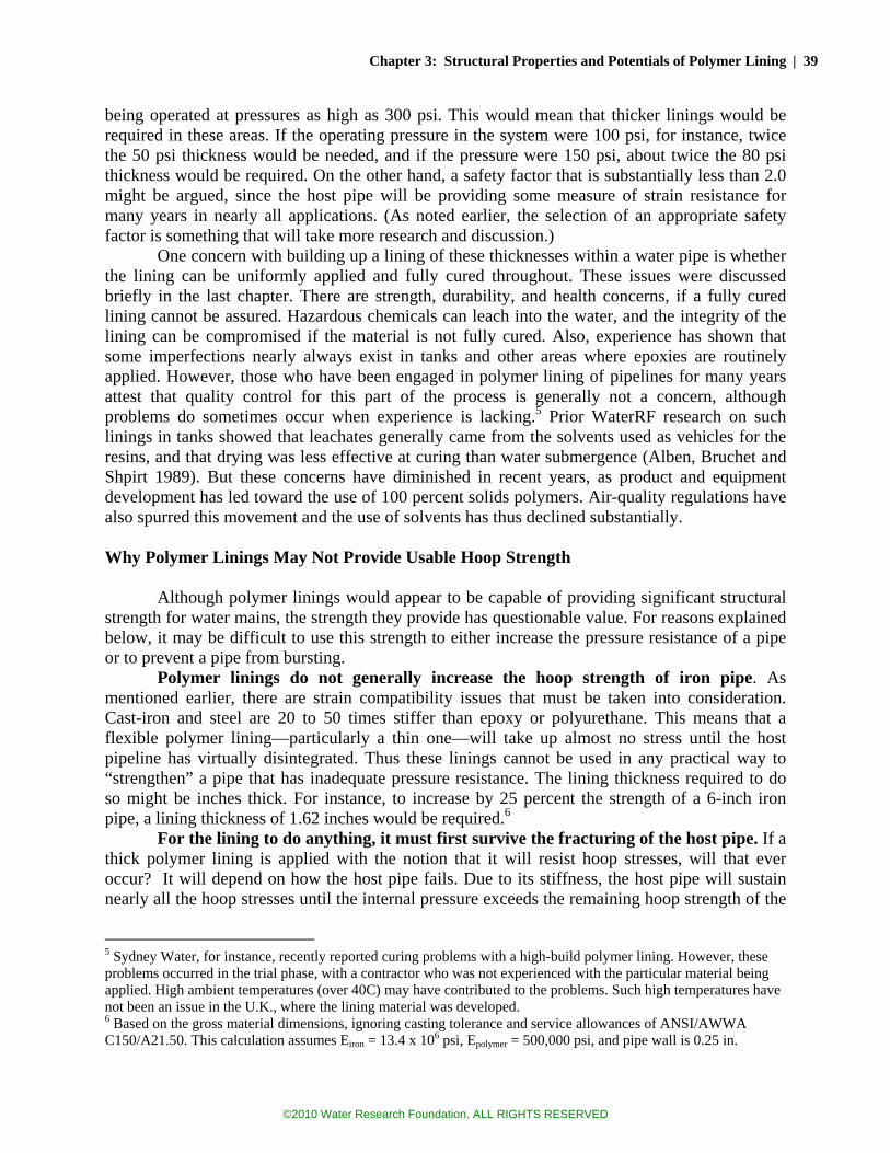
Chapter 3: Structural Properties and Potentials of Polymer Lining | 39
being operated at pressures as high as 300 psi. This would mean that thicker linings would be required in these areas. If the operating pressure in the system were 100 psi, for instance, twice the 50 psi thickness would be needed, and if the pressure were 150 psi, about twice the 80 psi thickness would be required. On the other hand, a safety factor that is substantially less than 2.0 might be argued, since the host pipe will be providing some measure of strain resistance for many years in nearly all applications. (As noted earlier, the selection of an appropriate safety factor is something that will take more research and discussion.)
One concern with building up a lining of these thicknesses within a water pipe is whether the lining can be uniformly applied and fully cured throughout. These issues were discussed briefly in the last chapter. There are strength, durability, and health concerns, if a fully cured lining cannot be assured. Hazardous chemicals can leach into the water, and the integrity of the lining can be compromised if the material is not fully cured. Also, experience has shown that some imperfections nearly always exist in tanks and other areas where epoxies are routinely applied. However, those who have been engaged in polymer lining of pipelines for many years attest that quality control for this part of the process is generally not a concern, although problems do sometimes occur when experience is lacking.5 Prior WaterRF research on such linings in tanks showed that leachates generally came from the solvents used as vehicles for the resins, and that drying was less effective at curing than water submergence (Alben, Bruchet and Shpirt 1989). But these concerns have diminished in recent years, as product and equipment development has led toward the use of 100 percent solids polymers. Air-quality regulations have also spurred this movement and the use of solvents has thus declined substantially.
Why Polymer Linings May Not Provide Usable Hoop Strength
Although polymer linings would appear to be capable of providing significant structural strength for water mains, the strength they provide has questionable value. For reasons explained below, it may be difficult to use this strength to either increase the pressure resistance of a pipe or to prevent a pipe from bursting.
Polymer linings do not generally increase the hoop strength of iron pipe. As mentioned earlier, there are strain compatibility issues that must be taken into consideration. Cast-iron and steel are 20 to 50 times stiffer than epoxy or polyurethane. This means that a flexible polymer lining—particularly a thin one—will take up almost no stress until the host pipeline has virtually disintegrated. Thus these linings cannot be used in any practical way to “strengthen” a pipe that has inadequate pressure resistance. The lining thickness required to do so might be inches thick. For instance, to increase by 25 percent the strength of a 6-inch iron pipe, a lining thickness of 1.62 inches would be required.6
For the lining to do anything, it must first survive the fracturing of the host pipe. If a thick polymer lining is applied with the notion that it will resist hoop stresses, will that ever occur? It will depend on how the host pipe fails. Due to its stiffness, the host pipe will sustain nearly all the hoop stresses until the internal pressure exceeds the remaining hoop strength of the
5 Sydney Water, for instance, recently reported curing problems with a high-build polymer lining. However, these problems occurred in the trial phase, with a contractor who was not experienced with the particular material being applied. High ambient temperatures (over 40C) may have contributed to the problems. Such high temperatures have not been an issue in the U.K., where the lining material was developed. 6 Based on the gross material dimensions, ignoring casting tolerance and service allowances of ANSI/AWWA C150/A21.50. This calculation assumes Eiron = 13.4 x 10⁶ psi, Epolymer = 500,000 psi, and pipe wall is 0.25 in.
©2010 Water Research Foundation. ALL RIGHTS RESERVED

40 | Global Review of Spray-On Structural Lining Technologies
host. Then as the host pipe fails, the hoop stresses are passed into the lining. But is the lining capable of then assuming these stresses?
For the lining to be able to take over the load, the host pipe might need to fail in a ductile manner. Perhaps a thinning of the pipe has occurred, and the pipeline yields, gradually stretching and transferring load to the lining. If this were to occur, a thick lining could eventually become a pipe unto itself—fully structural. However, this scenario seems very unlikely. Such ductility is not seen in most failing pipes, certainly not in cast-iron pipelines, and probably not in steel pipes. A more likely scenario would involve the gradual weakening of the host pipe until a sudden splitting of the pipe occurs. Then the ability for the lining to assume the hoop stress will depend largely on whether the lining itself survives the fracture. When this sudden splitting occurs, the lining will be called upon to stretch across a gap, and unless it detaches from the host, excessive strain will cause the lining to tear.
A similar consideration is discussed later in this section under “beam bending”, and the results of bench tests which explore this detachment phenomenon are presented in later chapters. HOLE AND GAP SPANNING
Like cement mortar lining, polymeric linings have the ability to span holes, gaps and other weaknesses in the host pipe. As such, these linings can effectively stop leaks, reducing maintenance costs, and extending the lives of the pipelines.
Unlike cement mortar lining, polymeric linings have the ability to span these weaknesses more reliably. Their ability to span holes is not based solely on anecdotal evidence and engineering calculations, but on a fair amount of testing performed with various linings. These tests have shown that various sizes of holes and gaps can indeed be spanned and rather high pressures can be sustained. These tests are presented in the next chapter.
Three failure modes are conceivable for polymer linings spanning holes: (1) punching shear, (2) bi-axial bending failure, and (3) tensile failure. In the first two modes, the lining acts like a flat plate, spanning across the opening. In a tensile failure mode, the lining functions like a membrane, stretching into a hemispheric shape, acting purely in tension, as it holds back the water, as shown in Figure 3.1. This third failure mode is based on the ability of polymeric materials to creep and deform plastically. As the material creeps, it loses strength, but by acting as a hemisphere rather than a plate, it becomes a more efficient structure. The degree to which the polymer can form itself in this manner without cracking depends upon its elastomeric properties, its long-term ductility, and other factors, as explained later in this chapter.
©2010 Water Research Foundation. ALL RIGHTS RESERVED
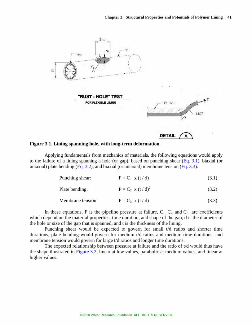
Chapter 3: Structural Properties and Potentials of Polymer Lining | 41
Figure 3.1. Lining spanning hole, with long-term deformation. Applying fundamentals from mechanics of materials, the following equations would apply
to the failure of a lining spanning a hole (or gap), based on punching shear (Eq. 3.1), biaxial (or uniaxial) plate bending (Eq. 3.2), and biaxial (or uniaxial) membrane tension (Eq. 3.3).
Punching shear: P = C1 x (t / d) (3.1)
Plate bending: P = C2 x (t / d)2 (3.2)
Membrane tension: P = C3 x (t / d) (3.3)
In these equations, P is the pipeline pressure at failure, C1, C2, and C3 are coefficients
which depend on the material properties, time duration, and shape of the gap, d is the diameter of the hole or size of the gap that is spanned, and t is the thickness of the lining.
Punching shear would be expected to govern for small t/d ratios and shorter time durations, plate bending would govern for medium t/d ratios and medium time durations, and membrane tension would govern for large t/d ratios and longer time durations.
The expected relationship between pressure at failure and the ratio of t/d would thus have the shape illustrated in Figure 3.2; linear at low values, parabolic at medium values, and linear at higher values.
©2010 Water Research Foundation. ALL RIGHTS RESERVED
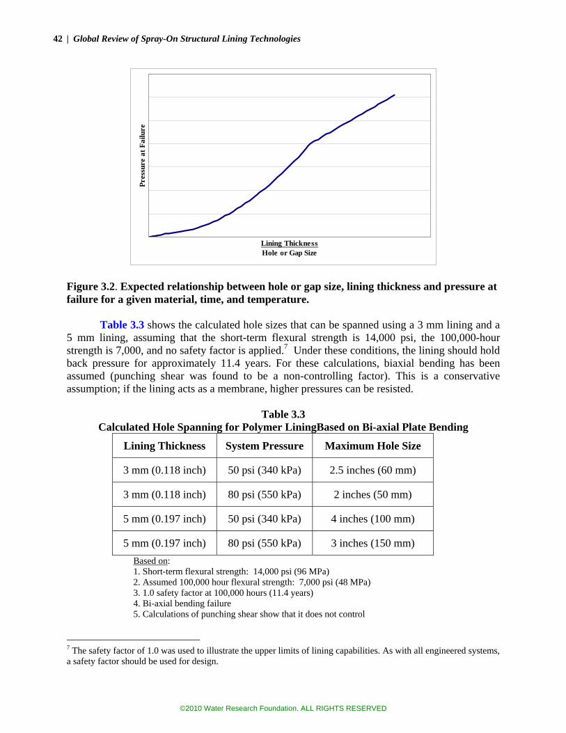
42 | Global Review of Spray-On Structural Lining Technologies
Lining ThicknessHole or Gap Size
Pres
sure
at F
ailu
re
Figure 3.2. Expected relationship between hole or gap size, lining thickness and pressure at failure for a given material, time, and temperature.
Table 3.3 shows the calculated hole sizes that can be spanned using a 3 mm lining and a
5 mm lining, assuming that the short-term flexural strength is 14,000 psi, the 100,000-hour strength is 7,000, and no safety factor is applied.7 Under these conditions, the lining should hold back pressure for approximately 11.4 years. For these calculations, biaxial bending has been assumed (punching shear was found to be a non-controlling factor). This is a conservative assumption; if the lining acts as a membrane, higher pressures can be resisted.
Table 3.3 Calculated Hole Spanning for Polymer LiningBased on Bi-axial Plate Bending
Lining Thickness System Pressure Maximum Hole Size
3 mm (0.118 inch) 50 psi (340 kPa) 2.5 inches (60 mm)
3 mm (0.118 inch) 80 psi (550 kPa) 2 inches (50 mm)
5 mm (0.197 inch) 50 psi (340 kPa) 4 inches (100 mm)
5 mm (0.197 inch) 80 psi (550 kPa) 3 inches (150 mm) Based on: 1. Short-term flexural strength: 14,000 psi (96 MPa) 2. Assumed 100,000 hour flexural strength: 7,000 psi (48 MPa) 3. 1.0 safety factor at 100,000 hours (11.4 years) 4. Bi-axial bending failure 5. Calculations of punching shear show that it does not control
7 The safety factor of 1.0 was used to illustrate the upper limits of lining capabilities. As with all engineered systems, a safety factor should be used for design.
©2010 Water Research Foundation. ALL RIGHTS RESERVED
Chapter 3: Structural Properties and Potentials of Polymer Lining | 43
These holes sizes might seem remarkably large, given the thin material that is being used. However the various manufacturer tests provided in the next chapter have confirmed the general magnitude of the values shown here. They are also reasonable compared to other materials that have been investigated, such as polyethylene linings. By comparison, the sizes of holes that can be spanned with standard cement mortar lining (0.19 inch thick), as discussed in Chapter 2, were less than 1 inch, and this is assuming that the mortar has not been cracked.
Boot, Guan and Toropova (1996) researched the stress-strain creep behavior of thin-walled medium density polyethylene (MDPE) linings considering various defects in the host pipe. In this series of experimental-analytical studies, a model was developed to determine the failure mode of a lining protruding through circular and rectangular gaps of various sizes. Steel pipe segments were lined with MDPE linings and internally pressurized. The maximum void size used for the tests was 2.4 inches (60 mm). This was chosen as the upper limit; the actual maximum hole sizes encountered in the field was believed to be 1.6 inches (40 mm) in the UK. The model was based on the elasto-plastic and linear viscoelastic behavior of MDPE. Two types of failures were observed, i.e., burst at the center of the void due to combination of biaxial bending and membrane tension, and failure at the periphery due to tension and transverse shear stress.
Their study showed that the failure of the MDPE due to bulging out of a hole on the host pipe is dependant on the ratio of void (hole) diameter (D) to lining thickness (t). For instance, for D/t = 9, failure pressure would be approximately 300 psi. This indicates that a 1.6-inch (40 mm) diameter hole could be spanned by a 0.175 inch (4.4 mm) thick MDPE lining with a factor of safety of 2 (150 psi internal pressure assumed).
While extruded MDPE linings appear to provide sufficient strength to span holes and gaps, the situation could be somewhat different for spray-on linings. The ability to span a hole for a spray-on lining will be dependent on its ability to form bonds between the spray-on lining molecules which is affected by the method of application. Accordingly, depending on the hole size, a spray-on lining may fail to form over an existing void, particularly if there are significant surface irregularities present (rust or scale). (If there is no existing void, and the rust hole is developing from external corrosion, there should be no question that the lining can bridge across the weakness.)
The ultimate tensile strength of MDPE varies from 3,770 to 4,800 psi, which roughly corresponds to the range of the ultimate tensile strength of epoxy and polyurethane strengths. Based on the Boot et al. results for MDPE, a spray-on lining should be capable of providing enough strength to span a rather large hole, if the lining can be formed at the required thickness over the hole.
Gap spanning analysis is similar to hole spanning, except that bending would be linear (i.e., one-way), not biaxial. The gap that can be spanned is thus shorter than the hole diameter that can be spanned. Gaps are presumed to form where a pipe has cracked or a joint is separating. In a 1999 study, Boot and Toropova looked at the gap spanning capabilities of MDPE pipelines and developed the following empirical formula based on curve fitting:
(3.4)
©2010 Water Research Foundation. ALL RIGHTS RESERVED

44 | Global Review of Spray-On Structural Lining Technologies
In this formula, D and t are the lining external diameter and thickness in mm, and pf50 is the 50-year failure pressure in bar.8 This expression assumes the gap remains constant as the lining deforms. Boot and Toropova felt this is a reasonable assumption, as friction between the two halves of a fractured pipe and the surrounding soil will provide significant resistance to axial movement of the host pipe. During laboratory testing, it was discovered that large deformations of the lining tended to pull the two pieces of pipe together, narrowing the gap. This narrowing of the gap occurs due to the large deformation and resulting curvature of the lining.
In a December 2006 study prepared specifically for a manufacturer, Dr. Boot predicted that yield stress would control the gap-spanning failure of a particular spray-on lining material. Because the yield strength of the spray-on polymer was roughly one-half the yield strength of the MDPE material, Equation 3.4 could be used with some confidence to predict the 50-year failure, except that the coefficient needed to be changed from “206” to “103”. Using this modified formula and applying a safety factor of 2.0, Boot predicted the following pressures could be sustained by a 3 mm (0.12 inch) lining in a 100 mm (4 inch) pipe (Table 3.4).
Table 3.4
Gap-Spanning Predictions for3 mm (0.12 inch) Spray-on Lining in 100 mm (4 inch) Pipe
Gap
Pressure at short-term failure
Pressure at 50-year failure
Safe working pressure
10 mm (0.39 in) 61 bar (890 psi) 21 bar (300 psi) 10 bar (150 psi)
20 mm (0.79 in) 35 bar (500 psi) 12 bar (170 psi) 5.8 bar (84 psi)
25 mm (1.0 in) 29 bar (420 psi) 10 bar (140 psi) 4.8 bar (70 psi)
35 mm (1.4 in) 22 bar (320 psi) 7.4 bar (110 psi) 3.7 bar (54 psi)
50 mm (2.0 in) 16 bar (240 psi) 5.4 bar (78 psi) 2.7 bar (39 psi) Notes: 1. 1 Bar = 0.1 MPa 2. Predictions are specifically for Lining D, a polyurea hybrid These predictions were subsequently tested in the laboratory. The results are found in the
next chapter, but average test values significantly exceeded these predicted values, and often reached the limit of the testing apparatus.
Slowing or stopping leakage due to holes and small gaps may be more important than it would seem. By stopping leaks, not only is water saved and the costs of the leak repairs avoided, but future pipe breakage may also be reduced. Leaks can contribute to external corrosion by providing electrolyte. Also leakage can contribute to the loss of pipe bedding material, resulting in bending of the pipeline; pipeline bending is the most common reason for pipe breaks. PIPE BENDING
The most common type of pipeline break is a circumferential fracture, and the most
common cause is bending of the pipe like a beam. Buried pipes generally are designed to be fully supported, and many can handle only a small amount of bending moment before they break. This
8 It’s noteworthy that this equation would reduce to Eq. 3.3, if the first exponent were -1.0 rather than -0.822.
©2010 Water Research Foundation. ALL RIGHTS RESERVED
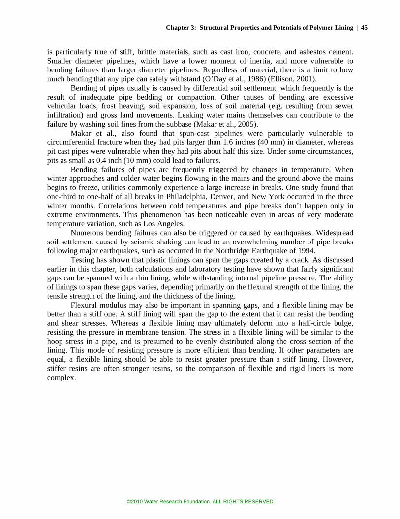
Chapter 3: Structural Properties and Potentials of Polymer Lining | 45
is particularly true of stiff, brittle materials, such as cast iron, concrete, and asbestos cement. Smaller diameter pipelines, which have a lower moment of inertia, and more vulnerable to bending failures than larger diameter pipelines. Regardless of material, there is a limit to how much bending that any pipe can safely withstand (O’Day et al., 1986) (Ellison, 2001).
Bending of pipes usually is caused by differential soil settlement, which frequently is the result of inadequate pipe bedding or compaction. Other causes of bending are excessive vehicular loads, frost heaving, soil expansion, loss of soil material (e.g. resulting from sewer infiltration) and gross land movements. Leaking water mains themselves can contribute to the failure by washing soil fines from the subbase (Makar et al., 2005).
Makar et al., also found that spun-cast pipelines were particularly vulnerable to circumferential fracture when they had pits larger than 1.6 inches (40 mm) in diameter, whereas pit cast pipes were vulnerable when they had pits about half this size. Under some circumstances, pits as small as 0.4 inch (10 mm) could lead to failures.
Bending failures of pipes are frequently triggered by changes in temperature. When winter approaches and colder water begins flowing in the mains and the ground above the mains begins to freeze, utilities commonly experience a large increase in breaks. One study found that one-third to one-half of all breaks in Philadelphia, Denver, and New York occurred in the three winter months. Correlations between cold temperatures and pipe breaks don’t happen only in extreme environments. This phenomenon has been noticeable even in areas of very moderate temperature variation, such as Los Angeles.
Numerous bending failures can also be triggered or caused by earthquakes. Widespread soil settlement caused by seismic shaking can lead to an overwhelming number of pipe breaks following major earthquakes, such as occurred in the Northridge Earthquake of 1994.
Testing has shown that plastic linings can span the gaps created by a crack. As discussed earlier in this chapter, both calculations and laboratory testing have shown that fairly significant gaps can be spanned with a thin lining, while withstanding internal pipeline pressure. The ability of linings to span these gaps varies, depending primarily on the flexural strength of the lining, the tensile strength of the lining, and the thickness of the lining.
Flexural modulus may also be important in spanning gaps, and a flexible lining may be better than a stiff one. A stiff lining will span the gap to the extent that it can resist the bending and shear stresses. Whereas a flexible lining may ultimately deform into a half-circle bulge, resisting the pressure in membrane tension. The stress in a flexible lining will be similar to the hoop stress in a pipe, and is presumed to be evenly distributed along the cross section of the lining. This mode of resisting pressure is more efficient than bending. If other parameters are equal, a flexible lining should be able to resist greater pressure than a stiff lining. However, stiffer resins are often stronger resins, so the comparison of flexible and rigid liners is more complex.
©2010 Water Research Foundation. ALL RIGHTS RESERVED
46 | Global Review of Spray-On Structural Lining Technologies
Figure 3.3. Lining spanning a gap caused by pipeline fracture.
Detachment of the Lining is Critical to Lining Survival
For the lining to span across a gap created by fracturing of the pipe, it must first survive
the fracturing event—and this is where adhesion is perhaps the most important consideration. If the lining is 100 percent adhered to the pipeline, then if the pipeline cracks, the lining would also likely crack, for if the movement of the pipeline is absorbed over an infinitesimally small segment of lining, the resulting strain is infinitely large.
Figure 3.3 illustrates a lining spanning a pipeline fracture. It shows that the lining has detached from the pipe wall by some distance (Lu). This allows the lining to stretch without tearing. If the unbonded lengths on both sides of the crack are equal, then strain in the lining is finite:
ε = γ / (2Lu)
Whether by design or by accident, it appears that spray-on linings do not always adhere that well to real-life (corroded) water mains. If the lining is not well bonded and cracking or joint movement occurs, it’s conceivable that the lining may be able to endure the movement with a finite strain, and leakage may not result, as the preceding figure illustrates. Whether the lining is stressed beyond its failure point will depend on the unbonded length of the lining (Lu) as well as the other parameters. This argues for a lining that is both flexible and not particularly well
(3.5)
©2010 Water Research Foundation. ALL RIGHTS RESERVED

Chapter 3: Structural Properties and Potentials of Polymer Lining | 47
adhered to the host pipe. The dilemma is that good adhesion is fairly important if the lining is to seal tightly at the corporation stops and other discontinuities.9
It should be noted that the Figure 3.3 illustration implies a sequence of events that would be rare in a water distribution system: (1) the pipe breaks, (2) the lining stretches, then (3) pressure is applied. In reality, pressure would be expected to be present during each step, not just at the end. This is an important consideration, as the pressure could certainly affect the adhesion of the lining to the pipe wall, thus keeping the lining from detaching. Any significant pressure should create significant friction, which would add to the mechanical bond that already exists between the lining and the wall surface. (Chapter 5 presents the results of some laboratory tests which sought to determine whether a lining could indeed detach, stretch, and survive a pipeline break, when pressurized at 50 psi (340 kPa).) ADHESION TO PIPE WALLS
Table 3.1 showed adhesion strengths for various linings. These adhesion strengths come
with two important caveats:
• Substrates vary. Tests were reported for cast iron, concrete, and steel. Adhesion to each of these could be expected to be different. In the reported tests, sometimes the substrate failed rather than the lining.
• These are laboratory tests, applied (presumably) to clean substrate. It is always known whether the substrates had a sand-blasted profile or not, but it is fairly certain they were cleaner than a typical old pipe that is cleaned in-situ.
The adhesion of spray-on linings to the host pipe is important at two phases of its life:
(1) adhesion during installation and (2) long-term adhesion. Each of these is discussed below. Adhesion During Installation
Adhesion during installation is critical with regards to successful application of the
lining. The risk of failure appears to increase with the diameter of host pipe. The shorter set-up times offered by polyurethane and polyurea coatings can also cause problems with blistering. Some of the material may set up before hitting the pipe wall or before thoroughly “wetting” the surface.10 Strict attention to surface preparation, including cleanliness and drying will help avoid these problems. Applying the materials at a proper temperature (not excessively warm) can also help. In fact, problems with pilot tests performed in Australia have been attributed to the difference in temperature between England (where the lining was developed) and Australia (where average temperatures can be significantly higher). The temperatures where problems may occur will depend on the characteristics of the specific product that is used.
Guan et al. (2003) reported substantial differences in adhesion between flexible and rigid polyurethanes. Flexible (elastomeric) polyurethanes are defined as isocayantes linked with
9 One solution may be to tailor the adhesion to different areas of the pipeline. At corporation stops and other areas where a good bond is desired, a grit-blasted profile and glue-like spot primer might be used. 10 “Wetting” the surface is thought of as being in a liquid phase long enough that air is driven away and the polymer penetrates the microscopic recesses in the substrate material, thus enabling a mechanical bond to develop with the polymer sets up.
©2010 Water Research Foundation. ALL RIGHTS RESERVED

48 | Global Review of Spray-On Structural Lining Technologies
diamines or polyols forming short polymer chains. Polyureas are included in this category. Rigid polyurethanes are formed by three dimensional intense covalent cross-linking between isocyanate and polyol molecules; thus forming a polymer with higher tensile strength, higher temperature resistance, and better adhesive properties in comparison with elastomeric polyurethanes.
Figure 3.4. Failure of elastomeric polyurethane lining. (Photo courtesy of Madison Chemical Industries)
The advantages of elastomeric polyurethanes and polyureas are higher resistance to impact and abrasion and greater elongation potential. The main shortcomings are lower tensile strength and poorer adhesion to substrate. Figure 3.4 shows adhesion failures of an elastomeric polyurethane lining. Such a lining might be applied for a slurry pipeline, where abrasion resistance is important. Most polyurethanes used in water main lining, on the other hand are rigid polymers and would not be as susceptible to this problem, although reports of adhesion problems have been received.11 Adhesion After Curing of the Spray-on Lining
Deb and others (2006) performed knife adhesion tests in accordance with ASTM D6677
on four different epoxy linings and one polyurethane lining, at thicknesses of 20 and 40 mils (0.5 and 1.0 mm). Although the data do not indicate a clear trend, the epoxy linings appear to demonstrate better adhesion than the polyurethane. The data also showed that adhesion somewhat decreased with time and elevated temperature (up to 35 ºC or 95 ºF).
In contrast, according to a field study conducted in the U.K., polyurethane demonstrated significantly better adhesive properties than epoxy (Oram et al., 2002). Methods used for cleaning the tested pipelines were drag-scraping, plunging, and water jetting. Adhesive strength was measured using loading fixtures with 0.5 in2 (2.94 cm2) surface area. Based on the results of this study, the adhesive strength of 60 mil (1.5 mm) thick polyurethane coating was 2,200 psi (15.25 MPa), which is two times higher than the adhesive strength of epoxy. Among the other findings of this study, spray-on coatings were not fully capable of covering the joints at this thickness (60 mil or 1.5 mm). For the most part, adhesion of polyurethane and epoxy linings has been sufficient to allow for subsequent tapping of the main without the need for specialized tools
11 Epcor, the water utility that serves Edmonton, Canada reported that a lining sprayed onto a pipe for demonstration purposes became detached as the pipeline was transported from Florida (where it was sprayed) to Edmonton.
©2010 Water Research Foundation. ALL RIGHTS RESERVED

Chapter 3: Structural Properties and Potentials of Polymer Lining | 49
or techniques. This has been proven through years of practice, particularly in the U.K. Such confidence does not yet exist for polyurea lining, which has only recently reached the market. LINING BUCKLING DUE TO EXTERNAL LOADS OR VACUUM
A large amount of research has been devoted to predicting the buckling behavior of pipe
linings subject to external pressures or internal vacuum. The focus of most of these studies has been gravity flow pipelines, where the pipeline is not intended to resist significant internal pressure and external loads are the major structural concern. In water system pipelines, where internal pressure exists nearly all the time, resistance to external loads are generally only a concern if the host pipe becomes extremely deteriorated. However, vacuum conditions certainly occur fairly frequently near the tops of hills during pressure transient (i.e., surge) events (Friedman et al., 2007), which could cause a poorly adhered lining to lose its bond and perhaps tear and fail.
Many studies have been conducted, examining the buckling resistance of thin CIPP, HDPE, and other unbonded plastic linings. These studies have resulted in standards for the design of such linings which were adopted in the 1980s, including ASTM F1216, the standard that is generally applied in the United States. Subsequent studies have shown that these standards may be overly conservative. Recent studies have shown that a very thin lining can stabilize a cracked and broken pipe, allowing even a badly deteriorated pipe to continue to carry soil loads, with little actual loading on the lining itself (Spasojevic et al., 2007).
The buckling of plastic linings depends upon the duration of the loading. Straughan et al. (1995) tested long-term structural behavior of lined pipelines and observed that viscoelastic behavior of the plastics leads to buckling of the lining under significantly lower pressures as the load is sustained over a longer period of time. Chunduru et al. (1996) studied the buckling of polyethylene (PE) linings under various pressure conditions and developed a buckling formula for HDPE linings. Bakeer et al. (2001) studied the long-term performance of HDPE, and observed that long-term buckling pressure is less than 50 percent of the short-term value. Accordingly, a design safety factor of 3 to 4 was recommended to be applied in order to establish the safe long-term resistance of a flexible lining. Because the chief concern for water main linings is probably vacuum loads due to very short-duration transient events, higher safety factors should not be needed, even for very frequent transient events.
If the lining is adhered to the host pipe, and if the host pipe is not in jeopardy of collapsing, then buckling of an adhered lining should not generally be a concern—even if the adhesion is only modest. Only a small amount of adhesion would be needed to maintain lining stability and prevent buckling.
Good lining adhesion is still important so that taps can be made, without detaching the lining. To keep the lining from being pushed away from the host pipe during the tapping process, hole saws are recommended. PREDICTING THE LONG-TERM BEHAVIOR OF POLYMERIC MATERIALS
All materials experience deformation under loads, and the amount of deformation
depends on the material’s characteristics. Force and deformation are stated in terms of stress and strain, where stress is the force per unit area and strain is the ratio of the change of a given length or volume to its original value prior to deformation (Δl/l). For most materials, small strains are
©2010 Water Research Foundation. ALL RIGHTS RESERVED

50 | Global Review of Spray-On Structural Lining Technologies
proportional to stress and this ratio is called the modulus of elasticity, in accordance with Hooke’s law. Hooke’s law applies very well to common construction materials such as concrete and steel under small strains, where these materials behave as solids. However, stretching of other materials may substantially elongate the chemical bonds between the molecules and may cause partial phase differences that make them demonstrate both solid and fluid properties. Polymers fall into a category of materials that nearly always have both solid and fluid properties, and polymers comprise the majority of spray-on lining being considered in this study.
For a material that perfectly obeys Hooke’s law, stress will be directly proportional to the applied strain, which is true for perfectly linear elastic deformation. On the other hand, for viscous (Newtonian) fluids, strain is dependent on both the amount of stress and the amount of time it is applied. Fluid strains are totally irreversible. Polymers fall into a group between the foregoing extremes; they behave both like a solid material and a viscous fluid depending on the amount of deformation, thus they are called “viscoelastic” materials. Two phenomena are commonly referred to in explaining viscoelastic behavior.
Creep: Viscoleastic materials lose their elasticity under stress. That is, the total energy spent on applying a force consists of deforming the material due to elasticity and heat generated by frictional force due to viscous deformation. In other words, mechanical energy is converted to mechanical and thermal energy in return.
Stress Relaxation: A way of measuring time-dependent viscoelastic behavior is keeping the strain constant and recording the stress over time. Naturally, stress should diminish over time due to loss in modulus. However, this process does not occur in direct proportion, as would be the case if Hooke’s law applied. Failure Stages
The long-term performance of linings will depend upon both the loading and material
properties. Linings may be subjected to external loads such as soil pressure, superimposed foundation and traffic loads, and groundwater pressure, but these are probably less important than loads due to system pressurization and pipe bending. Pressurization loads can include both normal operating loads, static loads, and pressure spikes due to hydraulic transients (Boyd et al., 2004a, 2004b). Fatigue loading, particularly from the starting and stopping of a pump station, for instance, may be a significant concern. Other cyclic stresses may occur from fluctuation of water tables, earthquakes and heavy vehicle traffic. Sustained, elevated, and frequent transient pressures can affect the molecular structure, dynamics, and conformation which would impact the mechanical properties of the polymer (Ferry, 1980).
The long-term mechanical strength of plastic pipeline materials has been the subject of considerable research. It is believed that the performance of spray-on polymer linings (epoxy, polyurethane, and polyurea) will exhibit many of the same characteristics that have been recognized in PVC and PE pipe materials, particularly slow crack growth.
ISO/TR 9080 (International Organization for Standardization) is a widely used standard for determining hydrostatic pressure classification of a plastic pipe material. It identifies three types of failure (Bergman, 1998): 1. Stage I—Ductile Failure or Ballooning
This type of failure is solely due to mechanical loading. As the load is sustained over time, polymeric materials tend to creep (or stretch), ultimately reaching a limit where failure
©2010 Water Research Foundation. ALL RIGHTS RESERVED

Chapter 3: Structural Properties and Potentials of Polymer Lining | 51
occurs. This type of failure is observable in short-term laboratory testing, but is seldom experienced in the field, unless an inadequate class of pipeline is used. In most cases, a safety factor of 2.0 or greater is applied to the 100,000-hour (11.4 year) strength of the material. Although pipelines that are older than 11.4 years will have safety factors less than 2.0, the safety factor should remain well above 1.0 (in theory) for at least 1000 years. 2. Stage II—Brittle Mechanical Fracture
Stage II failures occur due to slow crack growth. Long-term loading, particularly transient loading, causes a small crack to propagate through the material. This is seen in Figure 3.5 as the “knee” in the life expectancy curve. Resistance to slow crack growth is a function of the molecular structure of the polymer. Cracks may be started by small defects, occluded material, porosity, or scratches and gouges. Poor bedding and impingement on rocks can also be a cause. Slow crack growth is the cause of most failures of PVC and PE pipelines in the field, when not the direct result by third-party damage. Different polymers provide very different slow crack growth resistance. 3. Stage III—Brittle Chemical Fracture
Stage III failures occur when pipe materials degrade over time due to chemical processes. This failure is observed in Figure 3.5 as the steep portion of the curve, where pressure has little to do with failure. As the material of the pipe/lining degrades over time, failure at lower than the design value of critical stress is likely to occur (Gray, Mallinson and Price, 1981). Factors that would influence this behavior are exposure to sunlight, chlorine, and elevated temperatures. Plastic materials that are readily diffused by oxidants are more susceptible to this type of failure. Anti-oxidant compounds are generally added to PE and similar plastic materials to counteract such degradation.
Figure 3.5. Failure modes of polymeric pipe/lining over time. (Gray et al., 1981. Reproduced with permission from Maney Publishing: www.maney.co.uk/journals/prc).
Mechanical strength (hydrostatic hoopstress)
log Time (hrs)
log
Stre
ss (k
Pa)
Ductile
Brittle Chemical
Brittle Mechanical
©2010 Water Research Foundation. ALL RIGHTS RESERVED

52 | Global Review of Spray-On Structural Lining Technologies
Long-term Estimates of Strength for Plastic Materials are Extrapolations When discussing the structural capacity of water pipelines, the focus is generally on the
pressure ratings of the pipelines, or, in other words, the material’s ability to resist hoop stresses, with acceptable long-term safety factors. Most of the concepts for pressure rating calculations derive from steel and cast-iron pipelines, where yield stresses and ultimate strengths are rather sharply defined values that are not generally time or temperature dependent. With plastic materials, the strength declines continuously under stress. For the plastic material used in HDPE pipe, for instance, the strength at 100,000 hours (11.4 years) is about 50 percent of its original value. Even sharper declines in strength would be expected for the more elastomeric materials. The strengths of plastic pipeline materials are also highly dependent on temperature, with the common benchmark being 73.4 F (23 C)12.
Table 3.1 showed the tested values for flexural or tensile strength for various types of linings. It should be noted that test values may not be sufficient to judge the durability of a spray-on lining that is intended to provide structural value. Ductility (the ability to stretch without tearing or cracking) is probably of equal or greater importance. In a plastic material, resistance to slow crack growth is probably the most important ductile characteristic for long-term performance. Durability (the ability to avoid significant degradation over time) is also highly important.
ASTM D 2990 provides guidelines for testing polymeric materials for degradation due to creep. This includes uniaxial tensile, compressive, and flexural creep. Creep over time is measured by the change in deflection on the mid-span under the constant load, and this is defined as the change in strain over time which is calculated using the deflection values. This standard also includes methods for time extrapolation for predicting the long-term creep behavior of the tested material with the collected data during short-term tests. These methods include the Boltzman principle and time-temperature correlation. The Boltzman principle is based on predicting the strain at different levels of stress, i.e. superimposing the stress-strain curves for different levels of loads. It assumes that the tested material is linear viscoelastic, and that residual strains from previous loadings do not change the strain values for the following loadings. Hence, the total strain is:
))((.....))(()( 10110 −−−+−−+= nnnT ttJttJtJ σσσσσε where, J = Creep compliance (time dependent reciprocal of modulus).
The other superposition principle included in the standard is a time-temperature correlation. Specimens are tested for creep behavior (strain versus time under constant stress) for the same period at different temperatures (no higher than 100 ºC above the glass-transition temperature of the material). Then curves are shifted; for the temperatures above the glass transition temperature, the curves are moved to the right and vice versa for the curves that are below the glass transition temperature. The curves are then joined to each other to achieve a continuous long-term strain versus time curve using the relationship developed by Williams, Landel, and Ferry in 1955 (the WLF Equation).
12 At higher temperatures, such as might occur in Las Vegas and Phoenix, the pressure rating of a plastic water main may be less than is marked on the pipe.
(3.6)
©2010 Water Research Foundation. ALL RIGHTS RESERVED
Chapter 3: Structural Properties and Potentials of Polymer Lining | 53
)()(
logg
gT TTn
TTma
−+
−=
Here aT denotes the total horizontal shift, T = the tested temperature (above Tg) and Tg = Glass transition temperature, m and n = coefficients dependent on the glass transition temperature of the tested material.
ASTM D 2990 also includes methods of analysis of the relations between stress, strain, and time for viscoelastic materials. This is illustrated by a three dimensional sample plot of the three parameters (stress, strain, and temperature) and a relation between either two by holding one of the parameters constant. For instance, a stress versus time plot at different strain levels shows about a 50 percent decrease in stress in one day under 3 percent strain for propylene-ethylene at 20 ºC obeying the power law (Nutting Equation):
ntKt σε =)(
where, K and n are temperature constants.
The ISO/TR 9080 standard is commonly used by industry in predicting the service life of
polyethylene pipe. The extrapolation based on the ISO/TR 9080 equation assumes a linear relationship between the effects of time and temperature on the mechanical strength (hydrostatic hoop stress). This assumption is based on empirical data rather than an analytical solution, and potentially includes fundamental errors. For instance, there is no evidence that time can be linearly correlated with temperature for thermoplastics. The effects of temperature on the physical and mechanical degradation of polymeric materials are complex and it may be misleading to correlate the results to room temperature conditions by establishing a “time-temperature” relationship.
Greenwood and Myles (1986) studied creep in polypropylene and polyester, with an instrument that measures strains on polymer yarns using an extensometer. Polypropylene is a widely used polymer for external coating of pipelines to protect against corrosion, and it may be a good alternative for internal lining due to its mechanical properties (4,800 psi tensile strength, 180,000 psi flexural modulus of elasticity13). Both materials were tested at 20, 40, and 60 percent of the ultimate tensile strength. It was noted that the initial strains for the polyester yarn was higher than that of polypropylene. However, the total strain on the polyester specimen was stable as opposed to the extensive creep observed in the polypropylene yarns. For instance, at a tensile load of 15 N (20 percent of the ultimate tensile strength), the total strain on the polyester yarn ranged between 2.5 and 3 percent in 10,000 hrs. For polypropylene, the total creep was significant as at 60 N (20 percent of the ultimate tensile strength), where the strain ranged between 0.5 and 2 percent in 10,000 hours. Molecular Structure and Polymer Strength
Polymers that are used for spray-on lining applications may have significant differences
in their durability, stiffness, ductility and strength characteristics, even when they may appear to be composed of the same type of material. To illustrate, there may be tens of different types of 13 Source: Boedeker Plastics, Texas
(3.7)
(3.8)
©2010 Water Research Foundation. ALL RIGHTS RESERVED

54 | Global Review of Spray-On Structural Lining Technologies
polyurethane or epoxy-based spray-on coatings. Their mechanical and physical properties may be very different depending on crystallinity, isotropy, and additives. Sustained and elevated transient pressures can affect the molecular structure, dynamics, and conformation, which would affect the mechanical properties of the polymer (Ferry, 1980).
The mechanical properties of polymers are a function of their molecular structures. Monomers in linear or branched polymers may react with each other creating covalent bonds and form a network-like structure. This phenomenon is called crosslinking, and vulcanization of rubber is an example of it. Crosslinking makes a significant contribution to the material’s molecular weight. Crosslinking also prevents polymer chains from flowing past each other. In other words, crosslinked polymers cannot regain their structure once they are melted and then solidified. These types of polymers are also called thermosets. One way of forming polyurethane is vulcanization. Polymer chains can be arranged in a crystalline or amorphous form. Basically, crystallinity of a polymer is about its stereoregularity in the way the polymer chains are formed. This topic is extensive, and there are several models used to explain crystallinity such as fringed, micelle, and lamella (Rosen, 1993; Challa, 1993).
Crystalline polymers have a regular chain configuration with little or no branching (e.g.; high density polyethylene), whereas for amorphous polymers chains are randomly configured. A polymer is usually made up of regions with both chain configurations, and the higher the crystallinity the less the branching and the greater the density. The molecular bonds for crystalline polymers have higher energies than amorphous polymers, and this makes them stiffer and denser than amorphous polymers. Oxidation and Chemical Degradation
Mechanical strength and physical properties of polymeric materials may also degrade
over time due to environmental effects. A common cause for deterioration is oxidation, which can be exacerbated by environmental effects. Figure 3.6 illustrates the changes that occurred in the ultimate flexural strength of CIPP specimens over 1000 hours, after being exposed to water with high concentrations of water treatment residuals (chlorine, chloramines, and fluoride) at room temperature and elevated temperatures (Sever et al., 2005). While this clearly shows that a loss of strength is expected to occur, it should be noted that the concentrations of chemicals used in this study were substantially higher than the values found in a typical drinking water distribution system. It is believed that the levels of chlorine, fluoride or chloramines that are normally found (≤ 3 mg/L) will have no significant effect on degradation of the polymers that are currently used as spray-on linings, although additional testing may be needed to confirm this.
©2010 Water Research Foundation. ALL RIGHTS RESERVED

Chapter 3: Structural Properties and Potentials of Polymer Lining | 55
01000
F-F90
F-Cl90F-CM90
F-Cl23F-CM23
F-B23
02000400060008000
10000
12000
14000
Ulti
mat
e Fl
exur
al S
tren
gth
(p
si))
Time (hrs)
Figure 3.6. Reduction in ultimate flexural strength of CIPP specimens after exposure to chlorine (Cl), chloramines (Cm), and fluoride (F) solutions.
OTHER POSSIBLE LINING MATERIALS AND VARIATIONS
Alternative Resins
In the wastewater industry, polyester and vinylester resins are the polymers of choice for most pipeline rehabilitation. However, there are regulatory compliance issues as National Sanitation Foundation (NSF) Standard 61 compliance is required in 44 of the 50 states, and these resins normally do not meet the provision of this standard. There are other polymeric materials that could be conceivably used for linings, and manufacturers in the United States and Europe are continually developing new formulations. However, epoxy, polyurethane, and polyurea are the polymers that have been found most suitable for spray applications.
Fillers
The economics of polymer lining are greatly affected by the thickness of the material. Resins are expensive to produce, and their costs are expected to increase at a higher rate than normal inflation, because they derive from oil and natural gas, which are non-renewable and will become scarcer over time. To minimize materials while maximizing thicknesses, fillers are often added. Polyvinyl chloride (PVC) pipe, for instance, which is now the most common material for new water mains, contains a substantial amount of filler material, to increase its thickness without adding substantial cost. This is also true of centrifugally cast and other types of fiberglass pipes. Inert China clay fillers are typically used in epoxy used to line pipelines (Deb et al., 2006).
©2010 Water Research Foundation. ALL RIGHTS RESERVED

56 | Global Review of Spray-On Structural Lining Technologies
Thermoplastics
Thick linings of linear low-density polyethylene (LLDPE) are routinely applied inside of pipelines in a factory setting, and tight-fitting high-density polyethylene (HDPE) linings can be inserted within pipelines in the field using one of several methods. Each of these cases, however, involves a slip lining process, wherein a PE tube or strips of PE material are pulled inside the pipe, then formed into the finished shape.
Several years ago, one enterprising company attempted to develop a method for lining pipelines in-situ with melted polyethylene. The polyethylene would be melted, pumped to the application device inside the pipe, which would then form the lining. It is not known whether the lining was spray applied, or extruded. Reportedly, technical difficulties lead to the demise of the company. However, if polyethylene could be spray-applied or extruded inside a pipeline, its ductile nature, and general lack of adhesion to the metal subsurface, could make it a good candidate for structural lining.
The physical and mechanical properties of polyethylene are dependant on its molecular weight distribution and density. Various additives and fillers are also used in forming the material. High-density polyethylene has excellent resistance to abrasive materials and can have excellent resistance to slow-crack growth, when properly specified. For these reasons, it has become the material of choice for water distribution piping in many European countries. HDPE also resists oxidation due to exposure to water; whereas, low density polyethylene is more susceptible to oxidation/embrittlement in water. The broken specimen shown in Figure 3.7 is 3 mm thick, and was bent (to 8 percent normalized deflection) mounted on a custom-design apparatus and exposed to water at elevated temperature (80 ºC) to accelerate the effects of exposure for 5,000 hours. At the end of the exposure the specimen was extremely brittle and ruptured along the mid-span. The 8 percent normalized deflection generated approximately 1,000 psi (7,000 kPa) initial tensile stress at the mid-span of the tested LDPE specimen.
Figure 3.7. A segment of a broken LDPE specimen had been exposed to 80 ºC for 5,000 hours. Note the cracks which developed over the surface, indicative of oxidation/embrittlement (Sever, 2006).
©2010 Water Research Foundation. ALL RIGHTS RESERVED

Chapter 3: Structural Properties and Potentials of Polymer Lining | 57
High-density polyethylene has much higher mechanical strength than low-density polyethylene; for instance, a commercially available regular polyethylene has as high as 120,000 psi secant modulus of elasticity14 (based on third party flexural strength test, Sever, 2006), whereas the secant modulus of elasticity is as low as 30,000 psi for low-density polyethylene. High density polyethylene has higher mechanical strength than the spray-on linings typically used in water main rehabilitation and it is a common lining and coating material for pipelines used in other industries (oil and gas lines).
The factory application of PE pipe linings is often done by an extrusion process. One problem with lining with polyethylene is its poor adherence to the host pipe. Therefore, it is often applied as the second or third layer of coating (or lining) on top of epoxy or mastic. Very often, the PE is assumed to provide mechanical protection of the epoxy, which in turn provides corrosion protection for the steel. In a recent paper, Argent and Norman (2007) reported the following as main reasons for poor adhesion of 3 layer HDPE coating with epoxy prime layer to the host pipe:
• Poor surface preparation; i.e., cleaning, roughening by sand blasting, and chemical treatment for better adhesion of the prime layer.
• Too low a temperature will prevent the lining from flowing and adhering to the host pipe. Other problems with multi-layer coatings with polyethylene indicated are (1) poor
performance of mastic if used as prime layer due to its susceptibility to oxidation/embrittlement and expansion/deformation at warm temperatures; (2) stress/corrosion cracking (SCC), where coating material specifications are not well prepared; (3) too high or too low melt flow viscosity; (4) stretching tenting over the seam weld; (5) using an incorrect grade of polyethylene; and (6) incorrect use of application equipment. Nevertheless, by using the right type of materials with stringent QA/QC procedures, multi-layer polyethylene coatings with an epoxy sub-layer appears to be viable method for coating of pipelines for corrosion protection. Such lining/coating systems are currently used for extremely corrosive environments, such as in highly salty environments, or to transmit sea water.
USE OF NANO- AND MICRO- PARTICLE COMPOSITES IN SPRAY-ON LININGS
Recent studies indicate significant improvements to the structural properties of polymers may be achieved by using organic or inorganic nano- and micro- particles. Use of these materials is becoming more common in other industries such as aerospace and automotive. Published material to date indicates more advancement in nano- composites using epoxy; however, material properties of polyurethanes have been improved as well by adding nano-silica (Zhou et al., 2002).
14 Stress versus strain plot for a typical polymer is curvilinear under viscoelastic deformation unlike an elastic material (say steel) for which stress increases linearly with strain under elastic deformation. ASTM D790 identifies two types of stress/strain ratio or modulus of elasticity, one is the slope of the secant through the stress-strain curve and the other is tangent to the curve at a specified strain.
©2010 Water Research Foundation. ALL RIGHTS RESERVED

58 | Global Review of Spray-On Structural Lining Technologies
2
3
4
5
6
7
8
9
10
0 5 10 15 20 25 30Mass of Modifier, %
Mod
ulus
, GP
aMica R120Cloisite Na+Cloisite 25ACloisite 30BNanomer I30EViscosity Limit
Figure 3.8. Tensile modulus of elasticity versus percent weight of modifiers which are produced from clays and aluminum silicates. Zero percent weight indicates unmodified epoxy. (Source: Kinloch and Taylor, 2006)
Kinloch and Taylor (2006) analyzed physical, morphological, and mechanical changes to epoxy created by the addition of inorganic (mica) and organically modified organoclays, with various concentrations of silicate up to 30 percent by weight. The results indicated significant increase to the fracture and tensile modulus of elasticity of epoxy (Figure 3.8).
The increase in elastic modulus is pronounced for the epoxy with potassium aluminum silicate, where the measured tensile strength of this composite was as high as 1.3 × 10⁶ psi (9 GPa). Although this is the high end of the tested specimens, moduli of elasticity of most of the other nano- or micro- composites tested were greater than 600,000 psi, which is 20 times higher than a typical, commercially available epoxy coating. Results of Kinloch and Taylor’s study suggest a substantial difference in terms of enhancing mechanical properties of epoxy due to the type of nano- or micro- particles added. While aluminum silicate appears to be more effective than organoclays, availability and cost advantage of organoclays may qualify them as a viable option as nano- micro- additives to unmodified epoxy spray-on linings.
Kinloch and Taylor (2006) avoided reporting results on the ultimate tensile strength of epoxy nano-/micro- composites, and attributed this approach to large variations of this parameter due to surface finish of test specimens. In contrast, in their experimental study, Zhou et al. (2002) reported tensile strength, along with other physical and mechanical properties of nano- and micro- silica added polyurethane films. Results of the tensile strength tests (in accordance with ASTM D412) from this study suggest micro-silica does not contribute to the tensile strength of polyurethane, whereas significant improvements were achieved to the tensile strength of the material by adding nanosilica.
©2010 Water Research Foundation. ALL RIGHTS RESERVED

Chapter 3: Structural Properties and Potentials of Polymer Lining | 59
Figure 3.9. Fracture surface of epoxy resin with poor (a) and good mixing (b). Clay particles can be easily seen in case of poor mixing. (Source: Zhao and Hoa)
Zhao and Hoa (2005) investigated the toughening of epoxy resins with micro and nano
particles. Their modeling results indicated an effect of particle size/partitioning and mixing on fracture mechanics of epoxy nano- composites. Their model is based adding nanoclays to epoxy, which others had found to improve mechanical strength of epoxy. The study found that thorough mixing was very important for toughening of the epoxy-nanoclay composites, as poor mixing resulted in increased stress intensity around the particles and less fracture toughness (Figure 3.9 a and b). Among the results of Zhao and Hoa’s model is the effect of the volume fraction of the nano particle (clay); results suggest that 10 percent by weight is the optimum value. Higher volume fractions did not increase toughness but caused higher stress intensities. In terms of particle size, the study suggests stress concentration around the particles decreases with the particle size and reaches a minimum for a particle diameter of 0.95 μm.
©2010 Water Research Foundation. ALL RIGHTS RESERVED

60 | Global Review of Spray-On Structural Lining Technologies
©2010 Water Research Foundation. ALL RIGHTS RESERVED

61
CHAPTER 4 STRUCTURAL TESTS OF POLYMER LINING BY MANUFACTURERS
In Chapter 3, the material properties of polymer linings were provided, and theoretical
structural strengths were discussed, using principals from mechanics. These structural strengths included the linings’ abilities to withstand hoop stress, span across holes, span across gaps, withstand a pipe break, and withstand a vacuum (or exterior load).
In this chapter, descriptions and results of laboratory tests performed on linings are described. These tests have generally been performed by third-parties, including universities and testing laboratories, but not always. All of these tests were sponsored by the manufacturers, who furnished the results. The tests have been grouped into the following categories:
•• Hoop stress tests. These tests verify the ability of a lining to resist internal pipeline pressure, without assistance from the host pipe.
•• Hole bridging demonstration. These tests gauge the ability of a spray-on lining to bridge across an existing hole as it is applied.
•• Hole spanning tests. These tests measure the pressure that a lining can withstand when spanning across various sized holes in the pipe.
•• Gap spanning tests. These tests measure the pressure that a lining can withstand when spanning across various sized gaps in the pipe.
•• Gap spanning demonstrations. These tests illustrate the ability of a lining to undergo angular, axial, and shear movements of the host pipe.
•• Pipe breaking tests. These tests investigate whether a lining can endure the sudden fracture of the host pipe.
•• Lining adhesion / buckling tests. These tests investigate how well the lining adheres to pipeline surfaces, with various degrees of cleanliness and resists buckling.
•• Strengthening for external load. These tests determine whether a spray-on lining can improve the external load resistance of a pipeline.
HOOP STRESS RESISTANCE TEST
Lining D – Short-Term Hydrostatic Burst Tests Table 3.2 showed that with rather modest thicknesses, some of the high-strength polymers
being used for lining water mains could be considered “stand-alone” pipes, particularly for small diameters. The manufacturer of Lining D conducted hydrostatic testing to determine the ability of its lining to resist hoop stress. The intent was to investigate whether the lining meets the criteria for a Class IV (fully independent) lining, per Appendix A of AWWA Manual M28.
Two tubular samples were prepared by applying the lining inside cylindrical molds to a thickness of 0.12 inches (3 mm). After the outer mold was removed, the samples were delivered to the independent testing laboratory for hydrostatic burst tests, to be conducted in accordance with ASTM D1599-99, Standard Test Method for Resistance to Short-Time Hydraulic Pressure of Plastic Pipe, Tubing and Fittings. The test method was modified to accommodate the samples. The samples were cut into three specimens each.
©2010 Water Research Foundation. ALL RIGHTS RESERVED

62 | Global Review of Spray-On Structural Lining Technologies
Of the six total specimens, only one achieved its burst pressure, which was reported as 500 psi. This was 4-inch (100 mm) specimen. Each of the other five specimens started leaking at the seals before a burst pressure could be reached. The laboratory indicated the samples were significantly out-of-round, which caused the poor seal. The manufacturer believed the sealing difficulty resulted from the elastomeric (i.e., flexible) properties of the lining.
Testing was conducted at a temperature of 72 F (23 C), after samples were immersed for 1 hour, per the testing standard. Tables 4.1 and 4.2 show the results as reported by the independent testing laboratory.
Table 4.1
Short-term Hydrostatic Burst Test of 4-inch (100 mm) Lining
Specimen No. Pressure Observations
1 500 psi (3.4 MPa) burst
2 490 psi (3.4 MPa) held for 5 minutes
3 490 psi (3.4 MPa) held for 5 minutes
The two specimens that did not burst started leaking at an average pressure of 500 psi.
Table 4.2 Short-term Hydrostatic Burst Test of 8-inch (200 mm) Lining
Specimen No. Pressure Observations
1 300 psi (2.0 MPa) held for 5 minutes
2 300 psi (2.0 MPa) held for 5 minutes
3 300 psi (2.0 MPa) held for 5 minutes
These three specimens started leaking at an average pressure of 310 psi.
It should be noted that short-term burst tests such as these do not directly translate into safe operating pressures. Per water industry standards for plastic pipe materials, the operating pressure would be determined by applying a safety factor (likely to be 2 or higher) to a 100,000-hour yield strength. In these short-term tests, the bursting pressure is to be achieved very quickly, within 60 to 70 seconds. (Holding the pressure for 5 minutes, as reported above, is not a part of the standard test, but was an improvisation prompted by the leaking seals.)
HOLE SPANNING AND BRIDGING TESTS
Table 3.3 showed the estimated hole sizes that could be spanned using 3 mm and 5 mm high-strength polymer linings subjected to internal pressures of 50 psi (0.3 MPa) and 80 psi (0.5 MPa). The estimated size of holes that could be spanned ranged in size from 2.5 to 4 inches, assuming a life expectancy of 100,000 hours (11.4 years). These sizes were based on structural calculations, using the material properties shown in Table 3.1.
©2010 Water Research Foundation. ALL RIGHTS RESERVED

Chapter 4: Structural Tests of Polymer Lining by Manufacturers | 63
Several manufacturers have performed tests of various types, which demonstrate that indeed significant holes can be spanned, and very significant pressures can be sustained. Reports were provided for Linings A, C, E, and F. Manufacturers have also demonstrated that during the application process, lining can sometimes bridge across existing holes. The description of these tests follows.
Lining A – Hole Spanning Test
Lining A is a high-strength, 100 percent solids, epoxy lining, with NSF Standard 61 certification. The testing which is described here was performed by the manufacturer, under the supervision and oversight of Dr. Kent A Harries, an Assistant Professor of Structural Engineering and Mechanics, at the University of Pittsburg. Tests were performed on November 21, 2007.
Two specimens were tested; both were 4-inch in diameter, epoxy-lined Schedule 40 steel pipe. Each specimen had six holes ranging from 1/4-inch to 3/4-inch in diameter that were drilled in the pipe before lining. One specimen had a plain epoxy lining, 0.25 inches thick. The other had a lining of epoxy impregnated felt, with an impermeable membrane (similar to cured-in-place pipe lining). Prior to the test, the specimen with plain epoxy had been pressurized on at least four occasions to 1000 psi (6.9 MPa). The specimen with the CIPP lining was about 24-hours old at the time of testing.
In the lining of the pipes, the holes were also fully filled with epoxy. In other words, at the hole locations, the lining had greater than normal thickness, as it protruded into the holes and fully filled the thickness of the pipe.
Specimens were pressurized using a piston-style hand pump. Water was used for testing. The temperature of the water was not recorded, but an elevated temperature was not used. The test set-up is shown in Figure 4.1, which also shows the plain epoxy lining specimen at failure.
Figure 4.1. Pressure testing of Lining A. (Photo courtesy of Warren Environmental)
©2010 Water Research Foundation. ALL RIGHTS RESERVED

64 | Global Review of Spray-On Structural Lining Technologies
The rate of pressurization was such that 1000 psi was obtained in about 30 seconds. Upon reaching a pressure of 1400 psi, water began leaking from around the 3/4-inch hole of the epoxy lined specimen. For the CIPP lined specimen, a pressure of 2500 psi was achieved at which point a hair-line crack was observed around the 3/4-inch hole. Ultimately, a pressure of 3000 psi was achieved, but at this point the CIPP lining was clearly being pushed out of the hole.
In both cases, the linings failed by pushing a plug of material out of the holes, similar to a punching shear failure. The failures initiated on one edge of the holes, but with continuation of the testing, complete circular cracks developed around the edge of the holes.
Table 4.3 shows the shear stress that was calculated by Dr. Harries for the two specimens. This calculation takes into account the added adhesion provided by the epoxy that protruded into the hole.
Table 4.3
Shear Stress at Failure for Lining A
Lining Type
Pressure at Failure
Hole Size
Lining Thickness
Pipe Thickness
Shear Stress at Failure
Plain Epoxy 1400 psi (9.6 MPa)
0.75 inch (19 mm)
0.25 inch (6.4 mm)
0.24 inch (6.1 mm)
536 psi (3.70 MPa)
CIPP 2500 psi (17.2 MPa)
0.75 inch (19 mm)
0.25 inch (6.4 mm)
0.24 inch (6.1 mm)
1172 psi (8.08 MPa)
Lining D – Hole Bridging Demonstration
Lining D is a fast-setting, high-build, 100 percent solids. polyurea hybrid lining, with NSF 61 approval. The demonstration which is described here is taken from the literature of the company that makes the lining. No mention is made of third-party observation or participation.
A series of holes was dilled in a 4-inch (100 mm) pipe, ranging from 3 to 5 mm (0.12 to 0.20 inches). The holes were intended to simulate existing rust holes in a pipeline, over which a lining was applied. The pipe was then lined with a 3 mm lining, and the lining was examined internally for any sign of discontinuities. No discontinuities were observed. No pressure testing of the completed specimen was performed.
Lining E – Hole Bridging Demonstration
Lining E is a high-build polyurethane lining that is approved for lining in the U.K., but has not yet been submitted for NSF certification. The testing described below is taken from the literature of the company that manufacturers the lining. Reportedly, these tests were conducted in front of potential customers. Third party tests have not yet been performed.
©2010 Water Research Foundation. ALL RIGHTS RESERVED
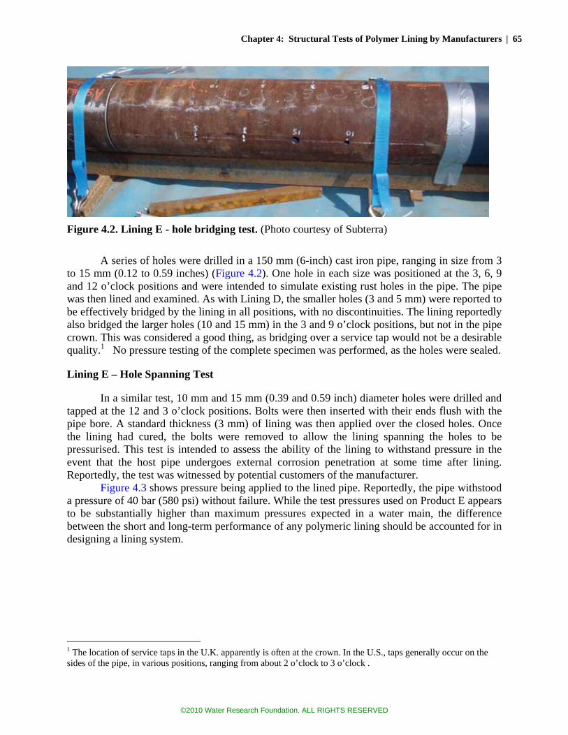
Chapter 4: Structural Tests of Polymer Lining by Manufacturers | 65
Figure 4.2. Lining E - hole bridging test. (Photo courtesy of Subterra)
A series of holes were drilled in a 150 mm (6-inch) cast iron pipe, ranging in size from 3
to 15 mm (0.12 to 0.59 inches) (Figure 4.2). One hole in each size was positioned at the 3, 6, 9 and 12 o’clock positions and were intended to simulate existing rust holes in the pipe. The pipe was then lined and examined. As with Lining D, the smaller holes (3 and 5 mm) were reported to be effectively bridged by the lining in all positions, with no discontinuities. The lining reportedly also bridged the larger holes (10 and 15 mm) in the 3 and 9 o’clock positions, but not in the pipe crown. This was considered a good thing, as bridging over a service tap would not be a desirable quality.1 No pressure testing of the complete specimen was performed, as the holes were sealed.
Lining E – Hole Spanning Test
In a similar test, 10 mm and 15 mm (0.39 and 0.59 inch) diameter holes were drilled and tapped at the 12 and 3 o’clock positions. Bolts were then inserted with their ends flush with the pipe bore. A standard thickness (3 mm) of lining was then applied over the closed holes. Once the lining had cured, the bolts were removed to allow the lining spanning the holes to be pressurised. This test is intended to assess the ability of the lining to withstand pressure in the event that the host pipe undergoes external corrosion penetration at some time after lining. Reportedly, the test was witnessed by potential customers of the manufacturer.
Figure 4.3 shows pressure being applied to the lined pipe. Reportedly, the pipe withstood a pressure of 40 bar (580 psi) without failure. While the test pressures used on Product E appears to be substantially higher than maximum pressures expected in a water main, the difference between the short and long-term performance of any polymeric lining should be accounted for in designing a lining system.
1 The location of service taps in the U.K. apparently is often at the crown. In the U.S., taps generally occur on the sides of the pipe, in various positions, ranging from about 2 o’clock to 3 o’clock .
©2010 Water Research Foundation. ALL RIGHTS RESERVED

66 | Global Review of Spray-On Structural Lining Technologies
Figure 4.3. Lining E - hole spanning test. (Photo courtesy of Subterra)
Lining F – Hole Spanning Test
Lining F is a high-strength, high-build, 100 percent solids, polyurethane lining, with NSF 61 approval. The testing which is described here was performed by the Louisiana Tech University, under the supervision of Dr. Mike Baumert, Assistant Professor of Civil Engineering in August 2008.
Figure 4.4. Lining F- hole spanning test set up. (Photo Courtesy of Sprayroq, Inc.) Flat panels of the subject polyurethane material were prepared in various thicknesses,
ranging from 0.25 to 0.35 inches. A total of 20 panels were prepared, from 0.1 inches (2.5 mm) to 0.4 inches (10 mm) thick. These panels were then sandwiched inside a very rigid test frame, with a pressure chamber on one side, and a flat plate on the other. Within the flat plate was a 3-inch diameter opening, across which the panel spans. Figure 4.4 shows the test set-up. Figures 4.5 shows the sandwiching of the test panel. Figure 4.6 shows an instrument in place to measure the bulging of the lining through the 3-inch (75 mm) opening.
©2010 Water Research Foundation. ALL RIGHTS RESERVED

Chapter 4: Structural Tests of Polymer Lining by Manufacturers | 67
Figure 4.5. Panel Sandwich. Figure 4.6. Instrumentation of 3-inch opening. (Photos courtesy of Sprayroq, Inc.)
The results of these tests are shown in Figure 4.7. Although these are short-term tests, the
results would imply that a lining of 0.25 inches (6.4 mm) would easily be able to withstand normal water system pressure in the long-term, while spanning a 3-inch (75 mm) opening. Not shown in this figure are two other tests. One panel was tested to 1022 psi (7.0 MPa), without failure. Subsequently the panel thickness was measured at 0.39 inches. Another panel was tested to 940 psi (6.5 MPa), also without failure. The thickness of this last panel is not known (because full test results have not been published), but it is 0.35 inches or greater.
Figure 4.7. Rupture pressures for panels spanning a 3-inch diameter opening. (Source: Sprayroq, Inc.)
©2010 Water Research Foundation. ALL RIGHTS RESERVED
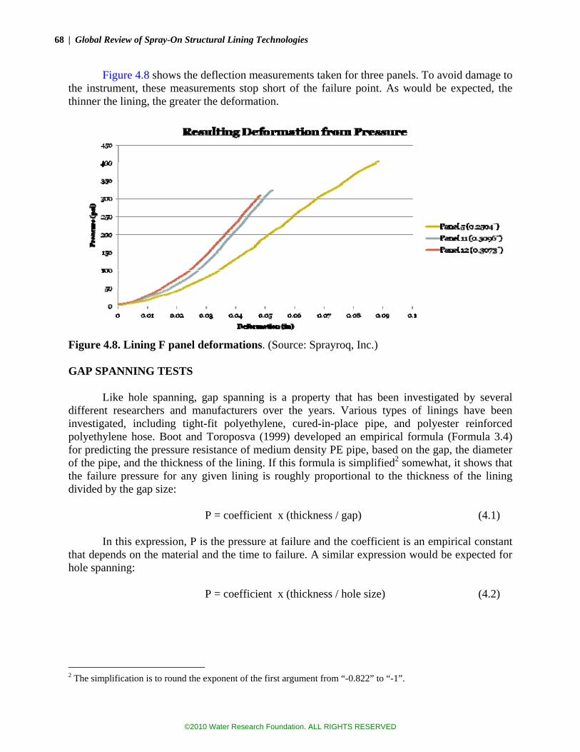
68 | Global Review of Spray-On Structural Lining Technologies
Figure 4.8 shows the deflection measurements taken for three panels. To avoid damage to the instrument, these measurements stop short of the failure point. As would be expected, the thinner the lining, the greater the deformation.
Figure 4.8. Lining F panel deformations. (Source: Sprayroq, Inc.) GAP SPANNING TESTS
Like hole spanning, gap spanning is a property that has been investigated by several
different researchers and manufacturers over the years. Various types of linings have been investigated, including tight-fit polyethylene, cured-in-place pipe, and polyester reinforced polyethylene hose. Boot and Toroposva (1999) developed an empirical formula (Formula 3.4) for predicting the pressure resistance of medium density PE pipe, based on the gap, the diameter of the pipe, and the thickness of the lining. If this formula is simplified2 somewhat, it shows that the failure pressure for any given lining is roughly proportional to the thickness of the lining divided by the gap size:
P = coefficient x (thickness / gap) (4.1)
In this expression, P is the pressure at failure and the coefficient is an empirical constant
that depends on the material and the time to failure. A similar expression would be expected for hole spanning:
P = coefficient x (thickness / hole size) (4.2)
2 The simplification is to round the exponent of the first argument from “-0.822” to “-1”.
©2010 Water Research Foundation. ALL RIGHTS RESERVED
Chapter 4: Structural Tests of Polymer Lining by Manufacturers | 69
Again, P is the pressure at failure and the coefficient is an empirical constant that depends on the material and the time to failure.3
Note that these two equations are essentially identical to Equations 3.1 and 3.2, which were developed for punching shear and membrane tension based on principles from mechanics. In both of these expressions, the curvature of the pipe wall is ignored, however as Boot and Toroposva have shown, the curvature (i.e., the diameter of the pipe) should have relevance. As the gap or diameter of the void increases in relation to the pipe diameter, the stress in the lining approaches the hoop stress condition. At the other extreme, as the diameter of the pipe increases in relation to the void size, the stress in the lining approaches the case of a flat plate.
Lining D – Gap Spanning Tests and Demonstrations
Lining D was subjected to a series of tests to ascertain its ability to withstand pressure while spanning across a pipeline gap, and to maintain its integrity as lateral, axial, and angular translations occurred.
Lining D - Gap Spanning Test
Table 3.4 provided the predicted pressure at failure for a 3mm lining spanning various pipeline gaps. These predictions come from a study performed for the manufacturer, by Dr. J. C. Boot, of the University of Bradford, U.K. After predicting the pressure at failure, laboratory tests were conducted to determine actual failure pressures.
Thirteen samples were tested. The samples were prepared by taking a 0.6 m section of lined pipe, and carefully cutting out a ring section, without damaging the lining. Various widths of rings were removed, corresponding to the gaps which were to be tested. For each sample, the lining thickness was measured at the ends of the pipe and at the gap (after testing). The lining thicknesses had considerable variation—from a low of 1.83 mm to a high of 4.84 mm (0.07 to 0.19 inch). Fifty percent of the cross sections had variations in thickness of at least 1 mm (0.04 inch). The reason for this variation in lining thickness was not explained. Based on the study by Deb et al. (2006), such a large variation is probably unusual.
The testing was done with two different set ups, as shown in Figures 4.9 and 4.10. Initially the ends of the pipe were constrained and the middle section was free to move laterally. During testing, it was found that uneven bulging of the lining caused an angular deflection at the gap area. However, after restraining the pipe, and performing additional tests, no clear differences between the results of the first set up and the final set up were discernable. The researchers felt, however that the final set up was more representative of conditions that would be encountered in the ground, with the pipe constrained and restrained by soil on all sides.
3 The coefficients in these two equations will have different values but similar dimensions.
©2010 Water Research Foundation. ALL RIGHTS RESERVED

70 | Global Review of Spray-On Structural Lining Technologies
Figure 4.9. Lining D - Initial Set Up. Figure 4.10. Lining D - Final Set Up. (Photos courtesy of 3M Company) Lining failures occurred in various ways. In two cases, the sharp edge of the pipe cut into
the lining, as it bulged into the gap. In eight cases, a flap of lining was blown out. In four cases a pin-hole leak occurred at mid-span.4 Figures 4.11a, b, and c show representative failures.
Figures 4.11 a (edge cut), b (blow out) and c (mid-span pin hole). Arrows show failures. (Photos courtesy of 3M Company)
Table 4.4 shows the average results of these tests as compared to the predictions. It
appears that Dr. Boot’s predictions were conservative in all cases. In all but one case, the actual test results were at least 70 percent higher than the predictions. Interestingly, little difference in
4 This equates to 14 failures for the 13 samples. In one case, both an edge cut and a mid-span pin hole developed.
©2010 Water Research Foundation. ALL RIGHTS RESERVED
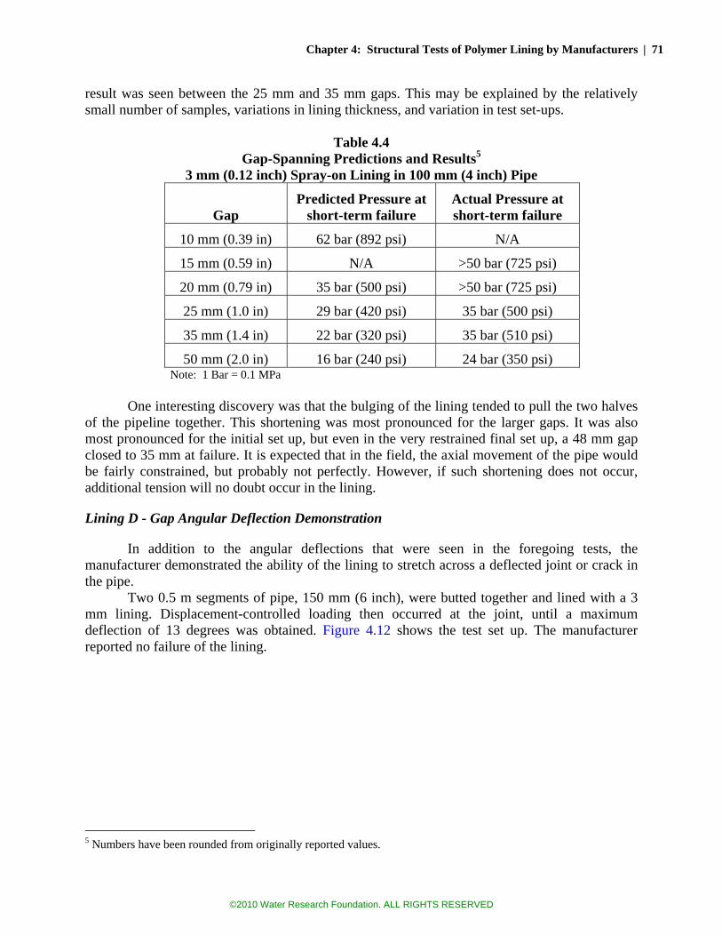
Chapter 4: Structural Tests of Polymer Lining by Manufacturers | 71
result was seen between the 25 mm and 35 mm gaps. This may be explained by the relatively small number of samples, variations in lining thickness, and variation in test set-ups.
Table 4.4
Gap-Spanning Predictions and Results5 3 mm (0.12 inch) Spray-on Lining in 100 mm (4 inch) Pipe
Gap
Predicted Pressure at short-term failure
Actual Pressure at short-term failure
10 mm (0.39 in) 62 bar (892 psi) N/A
15 mm (0.59 in) N/A >50 bar (725 psi)
20 mm (0.79 in) 35 bar (500 psi) >50 bar (725 psi)
25 mm (1.0 in) 29 bar (420 psi) 35 bar (500 psi)
35 mm (1.4 in) 22 bar (320 psi) 35 bar (510 psi)
50 mm (2.0 in) 16 bar (240 psi) 24 bar (350 psi) Note: 1 Bar = 0.1 MPa
One interesting discovery was that the bulging of the lining tended to pull the two halves
of the pipeline together. This shortening was most pronounced for the larger gaps. It was also most pronounced for the initial set up, but even in the very restrained final set up, a 48 mm gap closed to 35 mm at failure. It is expected that in the field, the axial movement of the pipe would be fairly constrained, but probably not perfectly. However, if such shortening does not occur, additional tension will no doubt occur in the lining.
Lining D - Gap Angular Deflection Demonstration
In addition to the angular deflections that were seen in the foregoing tests, the manufacturer demonstrated the ability of the lining to stretch across a deflected joint or crack in the pipe.
Two 0.5 m segments of pipe, 150 mm (6 inch), were butted together and lined with a 3 mm lining. Displacement-controlled loading then occurred at the joint, until a maximum deflection of 13 degrees was obtained. Figure 4.12 shows the test set up. The manufacturer reported no failure of the lining.
5 Numbers have been rounded from originally reported values.
©2010 Water Research Foundation. ALL RIGHTS RESERVED

72 | Global Review of Spray-On Structural Lining Technologies
Figure 4.12. Angular deflection demonstration for Lining D. (Photo courtesy of 3M Company)
This report shall not be reproduced, except in full, without written approval of Advantica. Figure 4.13. Test report for axial displacement demonstration. (Source: 3M Company)
Lining D – Gap Axial Translation Demonstration
A similar demonstration was performed, except that the two halves of a lined pipe were pulled apart at a controlled rate, until a gap of 3 mm (0.11 inch) was achieved. This axial translation was done with a small amount of pressure in the pipe: 138 mbar (2.0 psi). Pressure
©2010 Water Research Foundation. ALL RIGHTS RESERVED

Chapter 4: Structural Tests of Polymer Lining by Manufacturers | 73
was maintained for seven days, without leakage. Figure 4.13 shows the test report from Advantica, an independent third party testing company. 6
Lining D – Angular Deflection Cyclical Demonstration
Lining D also underwent a cyclical test, wherein the angular deflections alternated between 0 to 1 degrees at a frequency of 1 Hz. This demonstration was intended to illustrate the motions that might be created on at a pipe joint or crack due to heavy traffic loading. The specimen underwent 1 million cycles, sustaining a small amount of pressure (138 mbar or 2 psi). The entire test took 7 days to complete. The testing was performed by a third-party testing agency, which reported that failure of the lining did not occur.
Lining D – Transverse Shear Demonstration
A very similar demonstration was performed, where the two halves of the lined pipeline were displaced laterally, in a shearing movement. The displacement occurred in 12.5 mm (0.49 inch) steps, with each step held for one hour. Maximum displacement was 37.5 mm (1.5 inch), representing 25 percent of the pipe diameter of 150 mm (6 inch). This translation was again performed with a small amount of pressure in the pipe: 138 mbar (2.0 psi). Pressure was maintained for seven days, without leakage. Figure 4.14 shows the test set up. The testing was performed by a third-party testing agency.
Figure 4.14. Shearing demonstration for Lining D. (Photo courtesy of 3M Company)
6 The test report indicates a different lining material than is currently approved for the lining of water mains. It is not known whether this discrepancy is significant. This observation also applies to the other tests of Lining D reported on this page.
©2010 Water Research Foundation. ALL RIGHTS RESERVED

74 | Global Review of Spray-On Structural Lining Technologies
Lining E – Gap Bridging and Spanning, Demonstrations and Tests
Lining E - Gap Bridging
Figure 4.15 shows a demonstration set up where gaps exist in the pipeline. Plain-end pipe sections were aligned with open gaps between them, to assess the gap bridging capability of the lining. The width of the gaps were 3 mm (0.11 inch), 5 mm (0.20 inch) and 10 mm (0.39 inch). Lining E was then applied at a thickness of 3 mm (0.11 inch), and the pipe was assessed to determine how successfully the lining could bridge the gaps. This demonstration has reportedly been conducted several times in front of utility and contractor representatives.
The manufacturer reports that the 3 mm (0.11 inch) gaps where usually fully filled and that the wider gaps were either partially filled, or not filled.
Figure 4.15. Gap bridging demonstration for Lining E. (Photo courtesy of Subterra)
Lining E - Gap Spanning
In a similar set-up, the gap between two pipelines was temporarily filled with a 15 mm (0.6 inch) wide ring of polyethylene to give a flush inner surface. After lining, the PE ring was stripped away to leave the unsupported lining across the 15 mm wide gap for pressure testing. This test has been conducted several times, for various audiences. During one test, the lining failed at 30 bars (435 psi). This failure occurred at the sharp edge of the pipe. During several subsequent tests, the lining has held without failure, at pressure to 40 bars (580 psi). Figure 4.16 shows the lining at the gap, with the PE ring removed, prior to pressurization.
©2010 Water Research Foundation. ALL RIGHTS RESERVED

Chapter 4: Structural Tests of Polymer Lining by Manufacturers | 75
Figure 4.16. Gap spanning test for Lining E. (Photo courtesy of Subterra)
PIPE BREAKING TESTS
As discussed in previous chapters, there may be no property more desirable than the ability of a lining to survive the sudden fracturing of the host pipe. In order to do so, it is believed that the lining must be able to detach from the pipeline at the point of fracture, for sufficient distance that the subsequent strains in the lining are not excessive. Figure 4.12 clearly shows that Lining D has detached from the pipeline, as would be necessary for the pipeline to survive a fracture. In an early test of its product, the manufacturer of Lining D engaged Dr. J.C. Boot of the University of Bradford to see whether its lining could survive a sudden fracture.
A series of 100 mm (4 inch) cast iron pipes were lined with the subject product, to a nominal thickness of 3 mm (0.11 inch). Grooves were reamed around the outside of pipes, reducing the thickness of the 7 mm (0.28 inch) thick pipe walls by 2.2 mm (0.09 inch), 2.7 mm (0.10 inch), and 3.2 mm (0.13 inch). These grooves were to facilitate the cracking of the pipe and to simulate weakening that has occurred from corrosion. The pipes where then tested under displacement control until fracture occurred, and the lining evaluated. The test set up is shown in Figure 4.17.
After performing these tests, Dr. Boot concluded that a 3 mm (0.11 inch) lining within a 100 mm (4 inch) pipeline could indeed survive a circumferential fracture of the host pipe and remain intact. Although the testing was performed on an unpressurized pipeline, Dr. Boot expressed an opinion that plastic deformation of the soil around the pipe would absorb the additional energy that would result from pressurized contained fluid.
©2010 Water Research Foundation. ALL RIGHTS RESERVED

76 | Global Review of Spray-On Structural Lining Technologies
Figure 4.17. Pipe fracture test with Lining D. (Photo courtesy of 3M Company)
LINING ADHESION / BUCKLING TESTS
Table 3.1 presented adhesion test results for various linings. Performed in accordance
with various ASTM standards, these adhesion tests are not always illuminating, as the substrate materials varied and (more importantly) the substrate conditions were probably not similar to what is encountered in the field. Perhaps more useful, Deb et al. (2006) performed knife adhesion tests on 17 pipeline segments from 5 utilities with 8 different lining materials applied in-situ to old water mains. These results generally indicated satisfactory performance. The linings were primarily epoxy, but also contained a polyurethane product.
Two of the linings discussed in this chapter were further tested for adhesion by their manufacturers, as follows:
• Adhesion tests were performed on Lining D, applied to exhumed cast iron. The
surface was prepared using hand-tool cleaning, which approximates in-situ cleaning. The adhesion failed at the substrate interface, with a value of 7,600 kPa (1100 psi) achieved.
• External water pressure of 0.5 bar (7.2 psi) was applied to a lining similar to Liner D7 spanning a 50 mm (2.0 inch) gap between two sections of 150 mm (6 inch) pipe. The intent was to simulate a water head of 5 m (16 ft). Lining thicknesses of 3 mm (0.11 inch) and 4.5 mm (0.18 inch) were tested. Pressure was sustained for 1 month. The independent firm which conducted the tests reported that no detachment of the lining from the pipe wall could be discerned, and no penetration of water between the lining and the pipe wall occurred.
• Lining E was applied at 1 mm and 3 mm to a 150 mm (6 inch) steel pipeline, prepared by grit blasting. A full vacuum was applied (-1.0 bar-g, -14.5 psi-g). No disbondment or blistering was observed.
7 The test report indicates a different lining material than Lining D. It is not known whether this discrepancy is significant.
©2010 Water Research Foundation. ALL RIGHTS RESERVED

Chapter 4: Structural Tests of Polymer Lining by Manufacturers | 77
STRENGTHENING FOR EXTERNAL LOAD
Due to major differences between the elastic modulus of polymer linings and that of cast-iron or steel, it was noted in earlier chapters that polymers cannot significantly increase the strength of these pipes, but only may assume loads once the pipes crack or other develop holes and gaps. However, this restriction does not apply to concrete pipe, where the elastic modulus is of the same magnitude as high-strength rigid polymer linings. Moreover, polymer lining can add something that plain concrete does not have, significant tensile strength. Thus strengthening of a predominantly concrete pipe by lining is an achievable possibility.
Lining A was tested at the University of South Carolina, to determine whether it could significantly strengthen reinforced concrete pipe (RCP). The RCP was deliberately distressed, using both chemical and mechanical means. Segments of 18-inch (460-mm) diameter pipe were tested for three-edge bearing strength. Both epoxy-lined and non-lined (control) segments were tested, using three or four identical specimens. To simulate distressed pipe, the specimens were modified as follows:
• Abrasive chemical exposure: The RCP pipe segments were exposed to sulfuric acid
solution (molarity unclear). The pipes exposed to sulfuric acid only were identified as undamaged or moderately damaged based on acidity of the solution.
• Mechanical degradation: In addition to sulfuric acid exposure, pipe segments were mechanically damaged by using an angle grinder to carve as deep as 0.5 inches (13 mm) at the invert of the 2-inch (50 mm) thick pipe segment.
The carved parts were filled with “mastic” and 8-foot (2.4 m) long pipe segments were
lined with epoxy with one prime coat and two additional layers. The average thickness of prime was 0.8 inches (2 mm), which was achieved by multiple passes. Prior to the application of the prime coat, the interior surface of the pipes was pressure washed and exposed to acid treatment to increase surface roughness for better bonding between the lining and host pipe. In addition to the level of damage (i.e., sound or control, lightly damaged, or heavily damaged), another variable in host pipe condition was moisture as some segments were dried before application and some of them were kept wet.
Then the pipe segments were cut into 36, 12-inch (305 mm) long specimens for three edge bearing tests in accordance with ASTM C497. The test results indicated that the epoxy lining increased the strength of the pipe by up to 30 percent. Moreover, a significant difference between the strength of the wet-lined and dry-lined specimens was also noted. The study, by McNeice and Harries (2002) was sponsored by the manufacturer. The results are depicted in Figure 4.18.
©2010 Water Research Foundation. ALL RIGHTS RESERVED

78 | Global Review of Spray-On Structural Lining Technologies
Sound PipeDamaged Pipe
0
1000
2000
3000
4000
5000
6000
7000Load (lbs/LF)
Dry LinedWet LinedControl
Figure 4.18. Strength increase due to epoxy lining of RCP specimens. (The data used to generate this graph was taken from a report furnished by Warren Environmental.)
©2010 Water Research Foundation. ALL RIGHTS RESERVED

79
CHAPTER 5 LABORATORY TESTING OF MAINS LINED IN-PLACE WITH HIGH
BUILD POLYMER Concepts for several different laboratory tests surfaced during the review of manufacturer
tests and from interviews with various lining utilities. This chapter describes: (1) what the tests were intended to investigate, (2) initial testing concepts, (3) how the test were conducted, and (4) the results. Conclusions are also provided.
PIPE FRACTURE TEST - PURPOSE
As described in several places in this report, a very important property for a semi-structural lining would be the ability to survive the sudden cracking of the pipe, without tearing. Numerous studies had shown that many linings are certainly capable of spanning across existing gaps in pipelines, but an adhered, spray-on lining would not normally be expected to survive the actual opening of the fracture itself. If the lining is firmly adhered to the substrate, then strain in the lining approaches infinity, as the gap opens. Even a very pliable material would be expected to tear, if it is well adhered to the pipe.
The lining itself should not be expected to hold the crack closed. As mentioned in Chapter 2, the stress needed to crack a very deteriorated cast iron water main is in the order of 13,000 psi (90 MPa). When the pipe cracks, this stress passes into the lining, but is multiplied, because the lining is generally much thinner than the wall of the pipe itself. If for instance, the lining is 3 mm (0.12 inch) and the pipe wall is 6 mm (0.25 inch), then 13,000 psi of stress in the pipe wall would translate into 26,000 psi in the lining, exceeding by a fair margin the yield strength of the lining. As a consequence, the lining will try to stretch plastically, to relieve the stress. The problem is that if the lining is well adhered, all the stretching (all the strain) must occur within a very small length of material. An adhered lining is thus expected to fail.
In Chapter 4, testing sponsored by one of the lining manufacturers was described that showed its lining was capable of surviving the sudden cracking of the pipe.1 The lining survived by losing adhesion to the pipe wall near the area of the crack. This provided a greater length of material over which the strain could be absorbed. Instead of approaching infinity, the strain was something well within the capacity of the material. Other third-party tests performed by the manufacturer showed the lining was also capable of maintaining its integrity as the two sections of a cracked pipe underwent various angular, axial, and transverse movements. From these tests, it appeared that the lining might have a very beneficial property—the ability to adhere when needed, and to disengage when desired (something like a “Post-It” Note™). The manufacturer describes this property as having “greater cohesion than adhesion.”
Unfortunately, upon examination, an important element seemed to be largely missing from these tests. That element was internal pipeline pressure. In the first pipe, where the pipe is cracked, the study noted that testing was done on an unpressurized segment. In the tests involving angular, axial, and transverse movement of the “broken” pipe, the pressure applied during the translations was very small: 138 mbar (2.0 psi), much lower than would be found in any water system.
1 See page 70.
©2010 Water Research Foundation. ALL RIGHTS RESERVED
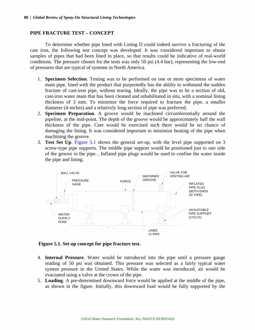
80 | Global Review of Spray-On Structural Lining Technologies
PIPE FRACTURE TEST – CONCEPT To determine whether pipe lined with Lining D could indeed survive a fracturing of the
cast iron, the following test concept was developed. It was considered important to obtain samples of pipes that had been lined in place, so that results could be indicative of real-world conditions. The pressure chosen for the tests was only 50 psi (4.4 bar), representing the low-end of pressures that are typical of systems in North America.
1. Specimen Selection. Testing was to be performed on one or more specimens of water
main pipe, lined with the product that purportedly has the ability to withstand the sudden fracture of cast-iron pipe, without tearing. Ideally, the pipe was to be a section of old, cast-iron water main that has been cleaned and rehabilitated in situ, with a nominal lining thickness of 3 mm. To minimize the force required to fracture the pipe, a smaller diameter (4-inches) and a relatively long section of pipe was preferred.
2. Specimen Preparation. A groove would be machined circumferentially around the pipeline, at the mid-point. The depth of the groove would be approximately half the wall thickness of the pipe. Care would be exercised such there would be no chance of damaging the lining. It was considered important to minimize heating of the pipe when machining the groove.
3. Test Set Up. Figure 5.1 shows the general set-up, with the level pipe supported on 3 screw-type pipe supports. The middle pipe support would be positioned just to one side of the groove in the pipe. . Inflated pipe plugs would be used to confine the water inside the pipe and lining.
MACHINEDGROOVE
VALVE FORVENTING AIR
INFLATEDPIPE PLUG(BOTH ENDSOF PIPE)
ADJUSTABLEPIPE SUPPORT(3 PLCS)
LINEDCI PIPE
WATERSUPPLYHOSE
BALL VALVE
PRESSUREGAGE
FORCE
4. Internal Pressure. Water would be introduced into the pipe until a pressure gauge reading of 50 psi was obtained. This pressure was selected as a fairly typical water system pressure in the United States. While the water was introduced, air would be evacuated using a valve at the crown of the pipe.
5. Loading. A pre-determined downward force would be applied at the middle of the pipe, as shown in the figure. Initially, this downward load would be fully supported by the
Figure 5.1. Set up concept for pipe fracture test.
©2010 Water Research Foundation. ALL RIGHTS RESERVED

Chapter 5: Laboratory Testing of Mains Lined in-place With High Build Polymer | 81
center pipe support and nothing should occur. The downward force would be calculated to achieve cracking of the pipe when the center support is removed (as described below).
6. Deflection. The testing process involved slowly lowering the center pipe support, causing the pipe to bend until a crack occurs at the groove. As soon as a crack was observed, the lowering of the support was to be halted. The intent was to mimic slow ground movement that eventually causes a pipe to break. Thus the deflection was to be performed slowly and in a controlled fashion, so that the crack does not open widely and artificially stretch the lining.
7. Observations. The lining would be observed for tearing. (If tearing occurs, it should be readily apparent through leakage of water.) Additionally, the width of the crack in the pipe would be measured. The entire test would be video recorded.
8. Conclusion. If cracking of the pipe occurs without tearing of the lining, the concept purported by the manufacturer would be confirmed. To verify that no tearing of the lining has occurred, the test set up would be maintained in a static condition (maintaining internal pipeline pressure) for one hour, during which the crack will be examined for water leakage.
9. Test Continuation. If the lining is leak-free after one hour, the deflection process would resume, by slowly lowering the center pipe support. This would continue until either leakage from the lining occurred or a practical limitation of the test apparatus was reached. The test would then stop and the water depressurized.
10. Measurement. Two measurements were to be taken at the conclusion of the test: (1) vertical displacement of the pipe at the crack location, and (2) crack width. There is a geometric relationship between these two measurements, which can be used as a cross check.
PIPE FRACTURE TEST – SET UP
The testing took place in the United Kingdom and was conducted under the supervision of Dr. David Lowe of Bodycote Testing Limited. The pipeline segments that were tested were all taken from old cast-iron mains lined in place in recent years. Each was 1-ft (300 mm) or longer in length. These samples were not intended to be representative of all such mains that have been lined with this product, but were merely samples that were made available for this project. Because usage of the high-build lining product is still fairly limited, and sample extraction is expensive, the research team felt fortunate in obtaining five suitable samples. The original goal had been to find and test at least one sample.
The testing set up as shown in Figure 5.2, was different from the concept discussed and shown on the previous page:
•• Instead of a center support, the underside of the pipe was supported using rubber straps to limit the deflection when cracking occurred.
•• Air was evacuated from the pipe end rather than from the top. (The laboratory provided assurance that all air would be evacuated before testing was initiated.)
•• Flange adaptors with blind flanges were used to cap the ends of the mains rather than inflatable plugs.
The full laboratory report is found Appendix B.
©2010 Water Research Foundation. ALL RIGHTS RESERVED

82 | Global Review of Spray-On Structural Lining Technologies
PIPE FRACTURE TEST – RESULTS
Five pipe samples were tested, and the lining survived without tearing in all five
instances. This result was surprising to the research team who believed that water pressure in the pipe would create enough friction between the lining and the rough inside wall of the old mains, that mechanical adherence would exist even without a physical bond between the lining and the metal.
The use of flange adapters instead of pipe plugs was a change that may have significantly altered the outcome of the tests. In all five cases, pressure was released immediately upon the cracking of the pipe. This occurred not through tearing of the lining, but due to leakage of water from the annulus between the lining and the pipe. Water entered the annulus area from the cut ends of the pipe water and flowed through the annulus to the fracture. Had pipe plugs been used rather than flange adaptors, water would have been contained within the lining and pressure would likely have been sustained for a longer period. There’s also reason to believe that the lining might not have survived the test at all (as explained later in this Chapter).
Figure 5.2. Actual set up for pipe fracture test.
©2010 Water Research Foundation. ALL RIGHTS RESERVED

Chapter 5: Laboratory Testing of Mains Lined in-place With High Build Polymer | 83
Figures 5.3, 5.4, and 5.5. Initial cracking of specimens.
Figures 5.3 through 5.7 show the five specimens following initial cracking of the cast
iron pipes. In one case, multiple fractures occurred due to significant corrosion pitting near where the pipe had been scored, and a pipeline fragment was dislodged (Figure 5.6). This did not damage the lining material.
Figures 5.6 and 5.7. Initial cracking of specimens. The first test was conducted at a speed of 8 inches (200 mm) of displacement per minute.
Subsequent tests were all conducted at only 0.2 inches (5 mm) per minute. The test rate did not appear to have an effect on the results. In all cases, water pressure was lost immediately after the pipes fractured. The testing laboratory noted that not only did the lining detach near the fracture location, but it slipped along the whole length of the pipe. This contributed to the rapid loss of water.
Figure 5.8 shows the high degree of deflection that was necessary to actually achieve tearing of the lining. This is probably not indicative of what would occur had pressure been sustained. If pressure had been sustained, not only would there be more stress exerted on the lining, but the lining would also have been better anchored, resulting in higher longitudinal strains.
©2010 Water Research Foundation. ALL RIGHTS RESERVED

84 | Global Review of Spray-On Structural Lining Technologies
Figure 5.8. Deflection needed for tearing of lining. Figure 5.9 shows a similar high degree of angular deflection. This picture is intended to
illustrate the sliding of the lining that occurred within the pipe. Prior to testing, the ends of the lining were flush with the ends of this pipe. This picture shows that the lining has retreated inside the 4-inch (100 mm) pipe at the crown by about 1.5 inches (40 mm). The amount of sliding shown in this picture is greater than what occurred in less deflected pipelines, but the effect was similar for all samples tested.
Figure 5.9. Deflection needed for tearing of lining.
RESULTS OF OTHER LABORATORY TESTS
The testing laboratory also performed various other tests on shorter samples obtained from various utilities. These tests were intended to confirm the material properties of Lining D, both short-term and long-term, when applied in-situ to cast iron pipe. The tests also looked at the quality of the lining application process, the uniformity of lining, in particular. These tests had been requested by several utilities and focused on Lining D as it was the predominant product that was being used for lining of water mains in the United Kingdom.
©2010 Water Research Foundation. ALL RIGHTS RESERVED

Chapter 5: Laboratory Testing of Mains Lined in-place With High Build Polymer | 85
Adhesion Tests
Adhesion testing was not performed. The testing laboratory had been commissioned to perform such testing on various samples of Lining D applied to cast iron mains in situ. However, as shown in Figure 5.10 and 5.11, a gap was visible between the lining and the pipe at the cut ends. When the pipe was cut longitudinally, it was possible to remove the lining without effort. Adhesion tests were therefore not performed, because adhesion was clearly negligible.
Figures 5.10 and 5.11. Gaps visible between pipe and lining. Figure 5.10 also shows lining tear produced from severe angular deflection. Figure 5.11 shows slumping of the lining material before curing. Lining Thickness Evaluations
The thickness of the lining was examined from two different batches. For each of these
batches, 7 samples were examined, both longitudinally and circumferentially. In one batch, the lining was fairly consistent. In the other case, the thickness of lining was quite variable. However, the specified minimum thickness was achieved in 96 percent of the 196 measurements taken. In the worst case, the lining only achieved 50 percent of the specified thickness at one point, but at most other points, the lining on this particular sample exceeded the minimum thickness.
Figure 5.11 (previous page) shows the one case where significant slumping of the lining occurred and a large variation in thickness was the result. Such slumping could have resulted from a slow cure. In another case, exceptionally thick lining occurred near the access pit for a short stretch, as the lining run was just getting started. Differential Scanning Calorimetry and Fourier Transform Infrared Spectroscopy
Differential scanning calorimetry (DSC) is a method to determine the melting and glass transitions of polymers. Two batches were examined, with seven samples each. As expected, no melting transition existed for this hybrid polyurea material. A glass transition, however, was determined to exist at about 65oC.
For one of the batches, a significant difference was found between the glass transition temperature found in an initial test and the temperature determined in a subsequent test. This difference implies that the lining material was not fully cured. The other batch exhibited consistent transition temperature for both tests.
©2010 Water Research Foundation. ALL RIGHTS RESERVED

86 | Global Review of Spray-On Structural Lining Technologies
A series of Fourier Transform Infrared Spectroscopy examinations found no significant chemical differences in the molecular structure of the lining materials from two batches of 7 samples each.
Mechanical Properties
Short-Term Stiffness
Three-point bend testing was performed on two batches of lining, each with 7 samples. For one batch, the mean short-term bending modulus was 749 MPa (108 ksi). For the other, the modulus was 541 MPa (78 ksi). There was also considerable variation within batches, with the modulus of one batch varying from 411 MPa (60 ksi) to 702 MPa (102 ksi).
Long-Term Stiffness
Creep was found to be quite significant for this material. The deflection of flat bar samples immersed in water was about 10 times greater after 350 hours of loading than the initial deflection. Based on this, the deflection at 50 years would be expected to be about 70 times the initial deflection.
Toughness
Charpy impact testing was conducted on a total of 11 samples taken from two batches of material. Samples were tested at 0oC. Table 5.1 shows the results.
©2010 Water Research Foundation. ALL RIGHTS RESERVED

Chapter 5: Laboratory Testing of Mains Lined in-place With High Build Polymer | 87
Table 5.1 Charpy Impact Testing Results – Lining D
Sample I.D. Impact Toughness (kJ/m2)
Impact Toughness (kJ/ft2)
6205-2 2.7 255
6205-4 2.7 255
6205-5 2.5 236
6205-6 2.4 226
6205-7 2.9 273
6216-3 4.9 462
6216-4 3.9 368
6216-5 2.9 273
6216-6 2.6 245
6216-7 2.8 264
6216-8 3.3 311
Average 3.1 288
Standard Deviation 0.7 70 The testing laboratory noted that values for polyethylene are typically 4 to 20 times
higher. This would indicate that this particular lining material is much more susceptible to rapid crack propagation than polyethylene.
DISCUSSION OF TEST RESULTS
In many respects, the tests results were very encouraging, but they are also rather disconcerting as regards this particular product’s ability to function well as a structural or semi-structural lining material in the long-term. The need for more testing was clear.
Pipe Fracture Tests – Potential Benefits
The ability of the lining to withstand a pipe fracture was very encouraging. As noted earlier in this report, pipe failure by beam bending has been found to be the predominant mode of failure for small diameter cast-iron mains.2 If a lining can survive such a bending-induced fracture, many additional years of service could possibly be added to the main.
Survival after sudden cracking should also be an important property for a lining when it comes to the spanning of holes and gaps in the pipe. It is reasonable to believe that many if not most of these holes and gaps happen relatively quickly and often involve some fracturing of the
2 See page 42.
©2010 Water Research Foundation. ALL RIGHTS RESERVED
88 | Global Review of Spray-On Structural Lining Technologies
pipe. For a lining to be able to span a hole or gap, it may need to detach from the host pipe in a similar manner, so that strains within the lining are finite and manageable.
The very low adhesion which allows the lining to survive the pipe fracture test is obviously an issue that needs greater examination. If the lining survives a facture but loses water due to leakage through the annulus, there’s not much benefit. Would this occur for pipe in the ground? Perhaps not. The short segments of pipe that were tested here no doubt magnify the effect of lining slippage. The shortness of the segments meant that lining discontinuities existed within a few feet of the pipe break. It was easy for water to travel the short distance from breach in the lining to the pipeline break. In practice, the breakage may occur a long ways from any discontinuity that would allow water into the annulus. If there is any friction between the lining and the pipe, the strain in the lining should diminish with distance from the break, up to the point where no slippage occurs.
Do discontinuities exist in actual systems? Discontinuities certainly exist at some pipe joints, as confirmed by video observations after lining. Often there is a gap between the hub of the bell and the end of the spigot, simply because the pipe was not fully pushed into place when it was laid in the ground. Where there’s an angular joint deflection or where movement of the pipe has occurred, gaps also exist at the joints. In Chapter 4, manufacturer testing showed that high-build linings could bridge across holes up to 5 mm (0.2 inch) in diameter, but not larger ones. Holes near the crown of the pipe were also more difficult to bridge. Thus, linings are probably discontinuous across any gap in a joint that is bigger than 5 mm. Discontinuities also exist at service taps, by definition. The service taps are areas where a hole in the lining purposely exists, and because the linings are applied with unidirectional sprayers, a shadow effect also occurs when a service-tap ferrule protrudes into the pipe.
Is detachment of the lining and leakage through the annulus a fatal flaw? Probably not. One can imagine various ways of either anchoring the lining in place or achieving better continuity across the gaps. Perhaps a filler material could be applied at the joints. Perhaps an epoxy primer could be applied that more firmly bonds the lining material to the host pipe at both the joints and the service taps. Although the application of such fillers and primers might create difficulties regarding same-day returns to service, these issues may not be insurmountable. For instance, if a slow curing epoxy is over coated with this fast-curing polyurea material, water quality testing may confirm that it is still safe to recharge the line with water shortly after applying the polyurea.
Pipe Fracture Testing was Inconclusive
Unfortunately, these tests do not show conclusively that a spray-on lining can survive a facture of the host pipe. The primary goal of these tests had been to perform the fracture testing with the pipe lining under pressure. This probably did not occur. Although the pipe was under pressure, the lining probably was not. It is quite likely that equal water pressure existed on both sides of the lining prior to pipe fracture. If this is the case, the water pressure did not act to create friction between the lining and the pipe wall, as intended.
As shown in Figure 5.11 and as discussed in the text of the laboratory report, gaps were visible between the lining and the host pipes at the cut ends. These gaps meant that water was present on both sides to the lining and the pressure was equal on both sides of the lining before the host pipe fractured. That explains why loss of pressure occurred instantaneously when the pipe broke. As far as testing whether the lining can detach from the pipe while under pressure, these tests were not essentially different from the dry tests performed by the manufacturer. In
©2010 Water Research Foundation. ALL RIGHTS RESERVED

Chapter 5: Laboratory Testing of Mains Lined in-place With High Build Polymer | 89
fact, these tests were even more forgiving—the water potentially acted like a lubricant, allowing the lining to slide more freely.
At this point, it is not known whether these tests are indicative of the conditions within most mains lined with this product. There are two possibilities: (1) water leakage into the annulus is a common condition, in which case the lining may survive a pipe fracture, but fail to hold in the water, or (2) the lining generally holds the water pressure, which creates friction between the lining and the host pipe, but this added friction may cause the liner to tear, when the pipe breaks. The first possibility would not be good—not only would the structural properties of the lining be negated, but the corrosion barrier would also be compromised. The second possibility would be more desired. It assures corrosion protection as well as allows the lining to span gaps and holes. But the question remains: will the added friction cause the lining to tear upon fracture of the host? Unfortunately, more testing is needed.
Other Concerns Regarding the Lack of Adhesion
The poor adhesion between the lining and the host pipe creates concerns regarding the lining’s primary function as corrosion barrier. Should water leak into the annulus from discontinuities at the joints and service taps, the corrosion protection provided by the lining is compromised, particularly if flow though the annulus occurs. If water enters the annulus and stagnates, corrosion would be limited, but if a continuous flow occurs, corrosion would be continuous.
In many systems, service taps are found near the crown of the pipe. The testing laboratory found that a visible gap between the lining and the host pipe existed at the crown of the pipes. The concurrence of a lining breech (i.e., the service tap) and a gap between the lining and the host pipe is an obvious concern.
The poor adhesion displayed in these tests by this particular lining also raises concerns regarding whether the pipe can be tapped in the same manner as other lined mains. For spray-on linings, it is generally assumed that the lining is adhered sufficiently to the host pipe at the service connection to allow the use of normal tapping tools and no special connections. If the lining is not bonded to the host, a special connection will be needed that seals to the lining in addition to attaching to the pipe so that leakage into the annulus does not occur.3
It needs to be noted that the cutting of these pipe samples may have exacerbated the adhesion issues. Heat generated by cutting has been known to cause detachment of linings. The current operational guidelines used in the U.K. recommends against the use of disc cutters and other tools that cause significant heating of the pipe. The cutting of pipe after lining is normally performed for quality verification only, and is not part of the lining process itself. Figure 5.12 shows lining that would be more typical at an entry or exit pit. In these locations, thicker-than-average coverage would be common, as discussed earlier in this chapter.
3 The testing laboratory had intended to examine samples of taps made after lining, but was not able to secure suitable samples. Similarly, pipeline joints were also to be examined.
©2010 Water Research Foundation. ALL RIGHTS RESERVED

90 | Global Review of Spray-On Structural Lining Technologies
Figure 5.12. Pipe sample taken from near an entry or exit pit. Adhesion might also be a concern where long-term dewatering of the pipeline occurs. It
is not known whether an unbonded lining made from this material has sufficient long-term stiffness to resist buckling under sustained external groundwater pressure. However, the short-term stiffness should be sufficient for a system shutdown lasting only hours.
Material Properties – Implications Regarding Structural Lining
The low values for long-term stiffness and the low resistance to slow crack growth indicate that this product is probably not suitable as a Class IV (fully independent) lining, per Appendix A of the AWWA Manual M28. As discussed in Chapter 4, ratings for plastic pipe materials are based on predictions of their 100,000-hour strengths. Furthermore, safety factors are chosen based on the material’s ability to resist slow crack growth. Because the current tests indicate low long-term strength and low slow-crack growth resistance, a lining fully capable of sustaining hoop stress would need to be quite thick—much thicker than was indicated in Table 3.2.
The low stiffness also means that the lining’s abilities to span cracks and gaps and hold back pressure are also more limited that the short-term tests reported in Chapter 4 imply. It had been shown that 350 psi (24 bar) of internal pressure could be sustained by a 3 mm lining spanning across a 2-inch (50 mm) gap. This was based on short-term tests. The long-term expectations would be very different.
This does not mean that the lining has no significant structural value. With shorter gaps and smaller holes, the lining should be able to resist normal system pressure for several years. A further mitigating factor is the confinement created by the trench backfill. For a polymeric lining material to fail plastically, it must deform (stretch) a lot. In the case where the lining is spanning a hole, the membrane will push out into the hole like a balloon. If the trench backfill pushes back with any significant resistance, the effective pressure on the lining is reduced and its longevity is increased. Because this material is able to sustain pressure at a high degree of deformation, the resistance of the backfill is potentially significant. This soil resistance would be contingent upon the hole in the pipe developing after the pipeline is lined. Otherwise, washout of the surrounding soil could be expected and the soil might provide little to no resistance. With or without such soil confinement, the long-term performance of flexible linings spanning holes of different diameters is not well understood.
©2010 Water Research Foundation. ALL RIGHTS RESERVED

91
CHAPTER 6 WATER QUALITY, HEALTH AND REGULATORY CONSIDERATIONS
Water traveling through distribution system infrastructure has been shown to decrease in
quality due to the uptake and introduction of contaminants from various sources, including the products of internal corrosion, permeation, and leaching of comprised distribution system components. Linings considered for water main rehabilitation should enhance the structural strength of the host pipe without degrading the quality of conveyed water. Different synthetic products used for spray-on water main linings may have different solubility characteristics that when exposed to drinking water supplies may leach minute quantities of contaminants over time.
Subtle changes or specific water quality conditions may exist in a distribution system that will exacerbate the leaching of chemicals from a polymeric spray-on lining, such as extensive holding time of the water in the main, the distribution of corrosive water, water with high residual disinfectant, or a combination of these conditions. Also, the type of residual disinfection used by the water purveyor, chlorine or chloramines, may also affect those conditions that would contribute to more or less mass transfer of contaminant from the synthetic lining to the bulk water. Likewise, the control of contamination from in-situ applied coatings requires suitable codes of practice for their application, in addition to those controls and methods that determine the ultimate in-place composition of the materials.
Volatile organic chemicals have been found to leach from applied coatings, some of which have been deemed to be potential human carcinogens. Taste and odor problems can also develop as a result of leaching of coating materials used on water mains. The United States Environmental Protection Agency (USEPA) regulates water quality by determining and enforcing maximum contaminant levels for thousands of chemicals that are monitored routinely by water purveyors. In addition, NSF International (formerly the National Sanitation Foundation) has been instrumental in developing a program to evaluate the leaching potential of different materials, and in doing so, certify that those materials used in drinking water systems do not pose a chemical health risk to consumers. Many states require certification to NSF International (NSF)/American National Standards Institute (ANSI) Standard 61 in order for a specific product or chemical to be used for potable water applications; consequently, manufacturers of spray-on structural lining technologies are aware, or should be aware, of these requirements.
NSF/ANSI STANDARD 61 DRINKING WATER SYSTEM COMPONENTS
In response to the USEPA, a consortium of organizations led by NSF developed voluntary third-party consensus standards and a certification program for direct and indirect drinking water additives. Other members of the consortium included AWWA, the Association of State Drinking Water Administrators, the Water Research Foundation (formerly the American Water Works Association Research Foundation), and the Conference of State Health and Environmental Managers. Following operation through a cooperative agreement with the USEPA, two NSF standards were adopted in on October 7, 1988: NSF/ANSI Standard 60 and Standard 61. NSF/ANSI Standard 60 (NSF 60), Drinking Water Treatment Chemicals Health Effects, was developed to address drinking water treatment chemicals serving as direct additives. NSF/ANSI Standard 61 (NSF 61), Drinking Water System Components Health Effects, was developed to address indirect additives, products and materials. Both standards are commonly
©2010 Water Research Foundation. ALL RIGHTS RESERVED

92 | Global Review of Spray-On Structural Lining Technologies
mandated by regulatory agencies to comply with minimum health effects requirements for chemicals and impurities that are imparted to drinking water.
NSF 61 covers indirect additives products and materials, including process media, protective materials, joining and sealing materials, pipes and related products, mechanical devices, and mechanical plumbing devices (including faucets). In essence, every material from the well or water intakes through to the faucet are covered. NSF 61 addresses crucial aspects of drinking water system components: whether contaminants that leach or migrate from the product/material into the drinking water are above acceptable levels in finished waters. The standard also covers products, components and materials. Items not covered by the NSF standard include point of use devices and fire hydrants.
When a material is certified under NSF 61, its certification indicates use restrictions on parameters such as maximum use temperature or surface area to volume ratio when the material is used in a finished product. This option allows manufacturers using certified materials to bypass some or all chemical testing when seeking certification, and assures that finished products meet all requirements.
Products such as pipe linings must be able to demonstrate that no chemicals or other contaminants will leach from the product when applied and cured per the manufacturers’ specifications. Section 5 of NSF 61 specifically addresses evaluations of spray on linings used in pipeline rehabilitation intended for immediate return to service. Although these certification processes defined in NSF 61 do cover the leaching of chemicals from spray-on structural lining technology, they do not establish performance or engineering design criteria, Because NSF 61 does not establish the aesthetic (taste and odor), chemical, and microbial growth resistance requirements for the various water system components and materials used in the construction of a drinking water treatment and distribution system, spray-on structural linings may cause taste and odor although the material meets the certification intent of Standard 61.
The preparation, conditioning and exposure protocols for barrier forming products and materials that prevent a coated surface from contacting the drinking water supply are covered in Section 5 of NSF 61. Product samples are exposed to an extraction water matrix. Four extraction waters are used to quantify contaminant leaching at pH 5, 6.5, 8 and 10. The extraction water comprises buffered and chlorinated distilled and deionized water that are freshly (daily) prepared, and analyzed for metals, non-metals or organics, and metals, respectively. Variables selected to simulate the application include surface area-to-volume ratio, soaking, exposure time, single or multiple sample sampling events, and contact via filling or emersion.
Following the exposure hold time, specific analyses are performed by material type for pipe/fitting/device materials, plastic materials, elastomers and barrier materials. In addition to the “minimum test battery”, analyses are also identified from the product formulation and its associated by-products for the materials in contact with water. This is based on the formulation of each material, maximum temperature during its intended use, and toxicological studies for chemicals within the product.
For paints and coatings, the manufacturer will submit to NSF prior to testing detailed use instructions that specify the appropriate preparation and application procedures including order of application for multiple layer systems, substrate preparation, subcomponent mixing ratio, induction time, thinning, application method and thickness(es), curing schedule and final cure time prior to water immersion. Coating systems that are composed of multiple products (such as primer, intermediate coat(s), and top coat including any thinners) are evaluated as an applied system. Use instruction indicating the coating/paint will rehabilitate existing pipe and that the
©2010 Water Research Foundation. ALL RIGHTS RESERVED

Chapter 6: Water Quality, Health and Regulatory Considerations | 93
water system can be returned to service within 48 hours following the final cure are evaluated as immediate return to service paint/coating systems.
Spray-on linings that have been demonstrated to meet NSF 61 have been shown to pose minimal health risks when used in water systems, provided that the spray-on linings are installed correctly. If spray-on linings are not installed correctly, the consumers of water passing thru that portion of pipeline that contains the faulty spray-on linings that are not fully cured, or installed properly, could be exposed to significant health risks. Because same-day return to service is an important goal for reducing the cost of water distribution system rehabilitation, it is critical that work be accomplished such that the risk of exposure to contaminants is essentially non-existent. For this reason the implementation of a spray-on lining system for pipeline rehabilitation, refurbishment and/or repair mandates the use of specific proven techniques and procedures that must adhere to all federal, state and local regulatory requirements.
DETERIORATION OF POLYMERIC MATERIALS
Problems associated with spray-on linings are similar to the general deterioration of polymeric (plastic) components commonly found in water distribution systems, and include the leaching of monomers, anti-oxidants and other organic chemicals that may or may not have regulatory significance.
Sadiq, Imran and Kleiner (2007) identified that leaching and permeation are the major cause of water quality deterioration in the polymeric components of distribution system infrastructure. The major water quality factors associated with polymer degradation are disinfection residual and temperature. Long-term deterioration mechanisms in polymeric pipes are not as well documented as those of metallic and cement-based pipelines, primarily because these mechanisms are very slow and the fact that the use of polymeric piping materials and linings are modern-day applications with little information available regarding long-term impacts. Deterioration mechanisms may include chemical and mechanical degradation, oxidation, biodegradation of plasticizers, and effect of solvents (Dorn et al., 1996). (It should be noted that many of the lining materials discussed in this report do not contain solvents or plasticizers due to water quality concerns.)
Contaminant Indicators
Organic chemicals comprise the predominant contaminants of concern relative to leaching and permeation in polymeric lines used in drinking water systems. These compounds include volatile, semi-volatile and non-volatile organics. While some of these contaminants are regulated, monitoring is often limited to the source water, in which case regulatory compliance monitoring may not detect contamination within the distribution system. However, the purpose of the NSF/ANSI standards is to avoid these events from occurring as a result of the use of a product or chemical in contact with potable water. It then follows that the water industry should become familiar with available certifications, such as NSF/ANSI Standard 61, and rely on these certifications to determine the relative suitability of one method or manufacturer over another, else more robust methods and procedures to detect and prevent contamination events from occurring when non-approved linings are used will be required. Despite these efforts, these certifications and approvals may not completely prevent from unintentional secondary impacts associated to taste and odor events, such that methods that are developed for monitoring prior to release for service should include measures to evaluate taste and odor in order to mitigate
©2010 Water Research Foundation. ALL RIGHTS RESERVED

94 | Global Review of Spray-On Structural Lining Technologies
problems from occurring at customer taps. Water purveyors should closely monitor taste and odor complaints during and after spray-on structural lining rehabilitation activities has occurred.
Water Quality Monitoring
Monitoring is an essential measure to determine when a newly lined water main is ready for service. This is done after the line has been isolated from the system, rehabilitated, flushed, pressure tested, and disinfected. Monitoring parameters normally include total coliform, HPC, chlorine residual, turbidity and odor. Since most contaminants associated with leaching are volatile and non-volatile organic chemicals, these parameters, with the exception of odor, are not likely to detect a contamination event. As a result, parameters should be identified based on the specific lining materials in use. One example is monitoring for benzene, toluene and xylene (BTX) and methyl-isobutyl ketone (MIBK) after installation of an epoxy coating. This not only verifies water quality degradation due to leaching, but can also uncover problems with the lining material or installation procedures.
It is important to note that the rate of leaching of organic compounds typically decreases exponentially over time. It follows that soaking newly lined pipes in water prior to service helps curtail the amount of leaching that will occur when the main is cleared for service. However, curing times are site and material specific and may need to be longer than the time the lining is fully immersed during pressure testing and disinfection. The application temperature, in particular, is a very influential variable. For these reasons, the lining application process must be monitored closely followed by specific water quality testing procedures and protocols.
Taste and Odor Issues
Polymeric materials have been found to impart taste and odor (T&O) to drinking water. Marchesan and Morran (2004) reported that in an evaluation of 314 materials investigated that had been used for drinking water applications, 14 of 29 specific products failed taste tests were polymeric materials, and that T&O often led to the identification of gross subsurface contamination. However, T&O should not be considered a reliable indicator of contamination detection or control, rather, specific chemical analysis is required.
While T&O complaints have previously identified contamination from polymeric materials, T&O is an unreliable indicator for detecting a contamination event when the risk threshold concentration is much lower than the T&O threshold. Ethylbenzene and xylenes are two contaminants where detection by T&O is likely to occur before significant health risks result from long-term exposure from consumption. However, exceptions exist for many contaminants including benzene, naphthalene, 1,2-dichloroethane, tetrachloroethylene (PCE), methyl isobutyl ketone (MIBK), vinyl chloride, and styrene. Adding to the health risks is the possible combined effect of release of multiple contaminants into the potable water supply, which is likely for petroleum-based lining materials.
Cement Mortar Linings
While fiber reinforced cement mortar linings could enable structural (or semi-structural) rehabilitation, use of cement may adversely impact water quality by causing changes in pH, alkalinity, and calcium hardness in the distribution system. These parameters are often set to leave water treatment facilities within a narrow range in an effort to maintain water quality
©2010 Water Research Foundation. ALL RIGHTS RESERVED
Chapter 6: Water Quality, Health and Regulatory Considerations | 95
during distribution to control metal release from premise plumbing, distribution system regrowth, and secondary disinfection. It is also important to recognize that certain water quality conditions may jeopardize the structural integrity of the cement mortar lining. For instance, acidic (low pH) waters or waters aggressive to calcium carbonate (high negative Langelier Saturation Indices) can cause leaching (Leroy et al., 1996). Waters with low mineral or alkalinity content has been shown to deplete calcium hydroxide contained in hydrated cements. Soft waters also cause leaching of calcium hydroxide which can also weaken the lining surface and possibly compromise its mechanical integrity.
Based on a study conducted by Douglas and Merill (1991) waters aggressive to calcium carbonate can cause significant leaching of cement compounds from cement mortar linings. In experiments where cement-mortar lined pipe segments were exposed to stagnant water, the pH increased from 7 to 12 pH units within a one-week period of time. Their results also showed effective cement mortar resilience when sealed with an asphalt-based coating material; however, the use of sealants may result in an increase in organics leaching into the water, causing adverse water quality impacts including chlorine residual depletion and taste and odor.
Another risk to water quality in cement-mortar lined pipelines is aluminum leaching. Aluminum is found in cement as tricalcium aluminate and this compound is believed to dissolve in water due to the following reaction (Berend and Trouwborst, 1999):
Ca3Al2O6 + 6H2O → 3Ca2+ + 2Al3+ + 12OH- Aluminum poses serious health risks to hemodialysis patients. The European Union (EU)
limits the aluminum content in drinking water to 30 μg/L. Aluminum is defined as secondary MCL by the USEPA and is hence limited to a range between 50-200 μg/L.
One study raised concerns about elevated levels of heavy metals in drinking water, where the cement comes from kilns where hazardous waste fuel is used for a portion of the fuel. Such kiln incineration is sometimes used as a method of disposal for hazardous waste. A mathematical leaching model indicated elevated levels of chromium and lead exceeding drinking water standards could be experienced (Guo, 1998).
Epoxy Linings
Modayil et al. (2002) compared the testing and evaluation of lining materials for drinking water pipeline rehabilitation. In addition to preventing corrosion and improving flow hydraulic characteristics, obtaining any semi-structural enhancement of rehabilitated pipes is considered to be beneficial. Although spray-on linings are traditionally considered to be non-structural, an innovative attempt is made in this study to evaluate the strength enhancement provided by an epoxy spray lining system. Pressure tests were performed by subjecting 20.3 cm (8 in.) diameter epoxy-lined ductile-iron pipe sections to an internal hydrostatic pressure of 827 kPa (120 psi). The surface of the 0.6 m (2 ft) long pipe sections had circular discontinuities of 0.63 cm (1/4 in.), 1.3 cm (1/2 in.) and 1.9 cm (3/4 in.) diameters to expose the epoxy lining. The results indicated that the epoxy lining sprayed at 2 mm (80 mils) thickness could protect underlying pipes that had corroded areas up to 3/4 in. diameter, under the test conditions. The lining sprayed at 1-mm (40 mils) thickness conventionally prescribed for holiday-free coating failed at the ¾-inch diameter exposed areas under the test conditions. The coating at 1-mm thickness would still likely extend service life of the pipe by reducing red water complaints. Full-scale field tests and bench scale leaching tests in the laboratory were also conducted as part of this project. Water samples were
©2010 Water Research Foundation. ALL RIGHTS RESERVED

96 | Global Review of Spray-On Structural Lining Technologies
obtained from customers' taps that were connected to freshly lined water mains. By testing various water quality parameters, water passing through the epoxy-lined mains was determined to be of excellent quality. No leached chemicals were detected in field or laboratory water samples as long as the system was flushed according to a manufacturer-provided standard lining procedure(s).
Studies investigating leaching of VOCs from polymeric linings indicate a significant release of VOCs in the short-term (up to 72 hours for epoxy). Materials published in the literature are generally in agreement that VOC release decreases to below detectable levels or to concentrations that do not impose a risk to quality and taste of water upon curing. Hence, for most cases, if not all, lining a deteriorated pipe with polymeric lining (particularly one with tuberculation) will enhance the water quality. Moreover, VOC release is not a concern for many of the lining materials described in this report, because they often contain 100 percent solids (no VOCs).
Alben et al. (1989a and 1989b) studied the mechanism of epoxy leachate from a lined tank over a period of 30 days. The results indicated an initial leaching of total organic carbon (TOC), which then decreased exponentially over time. The test water was granular activated carbon processed tap water having a pH of between 8 and 9 pH units. The initial leachate rates were from 40 to 187 μg/L-day; after 30 days the leachate concentration dropped to 8 to 37 μg/L-day. The research also indicated that the rate of leaching of TOCs from epoxy linings is highly dependant on the curing process; that is, longer curing periods reduced the rate of leaching and produced more stable linings. Benzene, toluene, xylene and TOC concentrations in stagnant water columns varied significantly for various epoxy resins assessed for a period of thirty days.
Another study on the leaching of epoxy linings was performed by the City of Calgary (Satchwill, 1998). Five different epoxy linings were applied on pipe coupons in two layers. Each layer was dried for 24 hours following application, after which the coupons were exposed to water for 72 hours. Results indicated significant amount of TOC was present in the test water, which ranged from 34 to 345 mg/L.
Heim and Dietrich (2007b) conducted an extensive study on the taste and odor of water in contact with epoxy lined copper pipes for the City of Calgary, Canada. Water stored in the pipes for 72-96 hours imparted a “plastic” smell. Analysis of VOC’s indicated a mix of compounds, including bisphenol-A, that accounted for the smell. For example, styrene gives off an odor of “airplane glue” (Tomboulain, 2004). A chlorinous smell, however, was not detected, as explained by the increased disinfectant demand of the stored water. Indeed the epoxy lined pipes consumed around 1.5 mg/L chlorine and 1.0 mg/L monochloramine. In addition, the stored water leached TOC and trichloromethane with time (Heim and Dietrich, 2007b). In the field study at a full scale installation site, though, consumers did not detect any noticeable smell under normal use (Heim and Dietrich, 2007b). In their experimental study Rigal and Danjou (1999) determined there was a dramatic difference in leaching of organic chemicals from an epoxy lined pipeline between 1 and 24 hours. After one hour of exposure of epoxy lined pipe to potable water 345 μg/L benzyl alcohol, 12 μg/L monoglycidyl ether of butane diol, 386 diglycidyl ether of butane diol, 72 μg/L diaminodiphenylmethane were detected in the sample that was analyzed by gas chromatography/mass spectrometry analysis. In contrast to the City of Calgary study, concentrations of these organic chemicals went below detectable limits after 24 hours. Regardless, the literature shows the magnitude of leaching organics from epoxy resins is strongly correlated to the curing process duration. (It should be noted that benzyl alcohol is not permitted in epoxy materials used in the U.K.)
©2010 Water Research Foundation. ALL RIGHTS RESERVED

Chapter 6: Water Quality, Health and Regulatory Considerations | 97
Leaching of the endocrine disruptor compound, bisphenol-A (BPA) from epoxy resins has been reported by Bea, Jeong and Lee (2002). BPA is commonly found in coatings used to line and protect the internal surface of water storage tanks. The tests showed BPA leaching in three separate test water matrices with higher leaching rates observed at increased temperature. In addition to the risk of BPA to human health, the investigators also observed higher bacterial counts in epoxy lined tanks when compared to stainless steel tanks, suggesting that compounds leached from epoxy linings may foster microbial regrowth.
Chantre (1989) evaluated the economics of the use of epoxy lining and the problems associated with deterioration of unlined cast iron mains in contact with soft aggressive surface waters. Because the pipes were mostly of sound structural condition, a planned program for relining using either cement-mortar or epoxy lining compositions was decided upon and implemented. A pilot-study was carried out in 1987-1988 in which the relining processes using either cement-mortar or epoxy resins were compared from two 6-month relining contracts of similar scope for mains ranging in size from 3 in to 6 in diameter. The installation challenges and relative costs of using the two methods showed a clear advantage favoring epoxy resin linings for smaller diameter pipes. Based on the results of the pilot scheme, a decision to rehabilitate further distribution pipes of sizes between 3 in and 8 in diameter using epoxy resin was taken, and between 1988 and 1992 more than 200 km (120 miles) of pipe was rehabilitated in this way. The cement mortar lining process was restricted to larger diameter pipes and trunk mains.
Polyurethane Linings
Some polyurethanes are subject to volatile organic compound (VOC) emissions as well. However, the curing time of polyurethanes is generally faster than epoxies. For example, in an experimental study conducted by Zhu et al. (1999) three different polyurethane coating materials were tested for VOC emission. Initially, the chemical composition of all three materials was determined by high performance gas chromatography and mass spectrometry (HP GC/MS). Once the VOCs in the tested polyurethanes were identified, their emissions were determined by the change of the weight of the material over time. Figure 6.1 indicates the remaining weight of the tested polyurethanes over time. Zero weight change (dw/dt) after seven hours for two of the three tested polyurethanes indicated no VOC emission at that point. The VOCs detected in all three materials were predominantly aliphatic hydrocarbons. UR3 contained less than 2 percent xylene and UR8 contained xylene (2 percent) and benzene (2 percent) as aromatic hydrocarbons. UR8 also emitted VOCs for a longer period of time than the others materials. Figure 6.1 also illustrates a correlation between experimental results and the proposed emission model developed in the study. It should be noted that the available polymeric water main linings are claimed to be free of VOCs by their manufacturers.
Leachate, Volatile Organic Compounds, and HDPE
Skjevrak et al. (2003) identified leached VOC’s from seven brands of HDPE pipes consistent with chemical compounds related to antioxidants as well as a wide class of aldehydes, ketones, terpenoids, and aromatic-carbons. Specifically, 2,4-di-tert-butyl phenol and 2.6-di-tert-butyl-benzoquinone were identified as major components of leached VOC’s from HDPE. Furthermore, Skjevrak found that VOC concentrations persisted during the 72 hour test period. Reductions in concentration required extended curing times greater than one month, with 50 percent of VOC concentrations at 72 hours remaining after 41 days. Skjevrak et al. (2003)
©2010 Water Research Foundation. ALL RIGHTS RESERVED

98 | Global Review of Spray-On Structural Lining Technologies
identified mainly alkyl aldehydes from PVC whose concentrations decreased with subsequent flushing.
Figure 6.1. Remaining polyurethane weight versus time. (Zhu et al., 1999)
PVC and PE
Polyvinyl chloride (PVC) mains have been found to leach elevated concentrations of vinyl chloride (VC) monomer. However, PVC is not problematic for liner applications since it cannot be used as a cured-in-place liner system. Instances where PVC leaching has been problematic appear to be limited to the mid-west for systems constructed in the 1970s. According to Flournoy et al. (1999), a rural system in Kansas was found to have VC levels as high as 14 µg/L, seven times the drinking water MCL of 2 µg/L. Following an analysis of this system among others (MS, IA, AR, and TX), instances were predominantly associated with pipe diameters less than 2-inches, temperatures above 50ºF, and greater than 1 day hydraulic detention time. Since that time, there have been no reported MCL violations for systems manufactured after 1977.
Studies by Heim and Dietrich (2007a) as well as Skjevrak et al. (2003) have found PVC pipes have mild effects on the odor of stored water. On the other hand, water stored in HDPE tends to have a “waxy/plastic/citrus” moderate odor as described by panelists. Also the threshold odor number (TON) varies between brands of HDPE, with the majority having a TON over 4, which exceeds the secondary TON MCL of 3 (Skjevrak et al., 2003). In addition, HDPE leached more TOC and had a greater disinfection demand than PVC (Heim and Dietrich, 2007). Similar to PVC, HDPE is not used for liner applications, but may offer a future application potential.
©2010 Water Research Foundation. ALL RIGHTS RESERVED

Chapter 6: Water Quality, Health and Regulatory Considerations | 99
DISINFECTANT RESIDUALS, WATER ABSORPTION AND POLYMERIC MATERIALS
A disinfectant residual is mandatory for compliance with the provisions of the Safe Drinking Water Act. However, it has been well documented that disinfectant secondary residuals can degrade polymeric materials within water distribution systems. Research by Brocca, Arvin and Mosbaek (2002) has shown that polymeric materials contain a variety of organic and inorganic additives in order to improve material durability, handling and product appearance. The absorption of water into polymeric materials has been shown to cause swelling and dissolution by additive leaching and eventual polymeric degradation (Fischer et al., 1993). Hassinen and colleagues (2004) demonstrated the deterioration of polyethylene pipes exposed to chlorinated water.
Lundback et al. (2005) showed that low levels of residual chlorine (<0.5 mg/L) could decrease the lifetime of polymeric piping by a factor of tenfold. Bonds (2004) demonstrated the effects of chloramine degradation on various elastomers used in drinking water distribution system appurtenances. The structural integrity of the polymer is affected with anti-oxidant loss that leads to increased brittle-failure of polymers as reported by Albertsson, Andersson and Karlsson (1987). Higher temperatures were reported by Gill et al. (1999) to accelerate the deterioration of polymeric components due to rapid loss of anti-oxidants within the pipe material.
Free chlorine decay rates in water distribution systems for bulk and wall demands were modeled and determined by Hallam and coworkers (2002).1 Their work found decay rates had different functional dependencies and comprises one of the few good quality determinations of in situ wall demand that have successfully overcome the difficulty of monitoring live systems. Wall demands were calculated from field measurements at eleven locations in a distribution system fed from a single source. A methodology for the laboratory determination was developed and shown to corroborate the in-situ results. Pipe materials were classified as either having high reactivity (unlined iron mains) or low reactivity (PVC, HDPE and cement-lined ductile iron). The results indicate wall decay rates for the former are limited by chlorine transport and for the latter by pipe material characteristics. The wall decay rate is inversely related to initial chlorine concentration for low reactivity pipes. In general, water velocity increases wall decay rates though the statistical confidence was low for low reactivity pipes. In addition, applications with a moderate biofilm coating showed no significant influence on the wall decay rate for low reactivity pipes.
Three analogous laboratory-scale water pipe systems were constructed to study the effects of three chlorine levels of finished water on the growth of biofilm (Chu et al., 2003). The experimental results indicated that the heterotrophic plate counts (HPCs), assumed to be an indicator of the presence of a biofilm, were approximately two to three orders of magnitude higher when no chlorine disinfectant was present, in comparison to those tests having low levels of chlorine present (0.3-0.5 mg Cl2 /L) and higher levels of chlorine present in the water (1.2-1.5 mg Cl2/L). The difference in HPC levels between lower chlorine levels in the water and higher chlorine levels in the water was less than one order of magnitude, as would be expected in a drinking water distribution system where free chlorine residual is present. Average biofilm formation rates were 325 pg/cm2 -day as adenosine triphosphate (ATP) for tests with chlorine-free water, 159 pg/cm2 —day ATP for low-chlorine water and 118 pg/cm2 -day ATP for test
1 The terms bulk demand and wall demand are typically used to distinguish chlorine demand exerted through interaction with constituents in the bulk fluid and with the pipe wall material contacting the bulk fluid, including the corrosion products, biofilms, and accumulated sediments at the pipe wall.
©2010 Water Research Foundation. ALL RIGHTS RESERVED

100 | Global Review of Spray-On Structural Lining Technologies
water containing the higher level of chlorine. Observations that were conducted using a scanning electron microscope (SEM) indicated that bacterial species separated from the biofilm were more complex than from the finished water, with gram-negative bacteria being the dominant form of these species.
Empirical models for chlorine dissipation in drinking water distribution systems have been developed by Arevalo and others (2004). The models were developed as a function of pipe material and water quality. PVC, galvanized steel, unlined cast iron and lined ductile iron pipes were taken from actual distribution systems and used to build eighteen pilot distribution systems (PDSs), which received finished water. Operation of the pilot distribution systems simulated normal operation circumstances. Hydraulic retention time was regulated using pumps to 5 days. Free chlorine and monochloramines were used in the study. The PDSs were monitored for time, temperature, pH, and total organic carbon. Separate models for free and total chlorine decay were developed. It was found that PVC had the least impact on chlorine dissipation in distribution systems, whereas, unlined cast iron experienced the highest chlorine demand.
In order to maintain the quality of drinking water, it is essential to have a complete understanding of underlying causes of its deterioration, according to Hulsmann and coworkers (1986). This is especially important where cast-iron pipelines are used, as in the Netherlands, for example, to transport drinking water. The Netherlands Waterworks' Testing and Research Institute relies on a variety of methods to determine the quality of water in the distribution system. The choice of methods depends upon the nature of consumers' complaints. The Institute employs an apparatus which can be connected to any pipeline to monitor oxygen, temperature, turbidity, pH, redox potential, conductivity and pressure. The results are interpreted by customized computer program. Also, the program considers parameters which can not be monitored continuously, such as, manganese and iron content and bacterial counts. Depending upon the problem, additional measurements such as calcium carry over, modified fouling index (dead-end filtration test), and evaluation of the internal surfaces of extracted pipe samples are utilized. PVC pipes were found to have less of an impact on water quality than cast-iron pipes. In PVC pipes the oxygen levels are much higher and turbidity levels were found to be lower than those in cast-iron pipes. Infrastructure renewal methods for old cast-iron pipes in the Netherlands range from complete replacement to flushing. However, it was determined that standard flushing procedures provided limited effectiveness. Methods of rehabilitation consist of air-scouring, swabbing with foam pigs, high pressure jetting, cement-mortar lining, and relining with a new pipe line. The analytical method represents a more systematic approach to deciding on a proper and cost effective method of responding to water quality problems through data collection and consideration of all the necessary information.
Kendig et al. (1992) characterized the mechanism of cathodic disbonding (CD) of pipeline coatings from steel pipe. They evaluated CD to (1) improve surface and coating preparation for resistance to CD, and (2) place currently used practices for evaluating CD resistance on a more rational basis. The approach requires characterizing the chemistry of surfaces undergoing CD and the chemistry of the disbonded zone. A method for directly transporting a metal sample from a disbonded zone to an ultra high vacuum for surface analysis using auger electron and photoelectron spectroscopies was developed. Results showed the environment within the disbonded zone produced by a standard CD test has a pH in excess of 13, which could lead to pipe exposure and water quality impacts. Electrochemical impedance spectroscopy (EIS) was also used to characterize the physical properties of the disbonded zone and the transport of water through typical fusion bonded epoxy (FBE) coatings. EIS
©2010 Water Research Foundation. ALL RIGHTS RESERVED

Chapter 6: Water Quality, Health and Regulatory Considerations | 101
demonstrates that disbonding of FBE from a contaminated substrate can result in shielding. However, the study also showed that well bonded FBE can take up to 20% water as determined from EIS without showing signs of corrosion of the substrate or coating degradation.
BIOFILM CONSIDERATIONS
Polyvinyl Chloride (PVC) and Polyethylene (PE)
Three studies confirm that plastic materials used in water distribution systems supported the lowest levels of biofilm than the many other available metallic and composite materials available in the marketplace. The findings provided in these three example studies corroborate LeChevallier et al. (1993) in that lower pipe reactivity and smoother surfaces lead to less bacterial regrowth when used as water distribution system pipelines. Consider the data collected by Cheng and Jung found that PVC had a biomass inventory one order of magnitude lower than cast iron. The researchers observed that pipe material affected fixed biomass accumulation more than water quality. PVC also showed the lowest bulk liquid heterotrophic plate counts (HPCs), while unlined cast iron exhibited the highest HPCs, along with the highest depletion of disinfectant residual. The corrosion products of the iron increased the disinfection demand, thus allowing biofilm to proliferate in low residual conditions (Chang and Jung, 2004).
A study conducted in Brussels by Niquette et al. (2000) also concluded that plastic pipe materials consistently supported low densities of bacterial biomass, even when incubated in waters of varying quality and sources. Water quality was found to vary in terms of residual disinfectant, biologically degradable dissolved organic carbon (BDOC) and source of supply. Holding the average carbon content, temperature of at 20o C and a chlorine residual at 0.03 mg/L within each bacterial cell, biomass densities on PVC and PE ranged from 7.0 x 10⁴ to 5.0 x 10⁶ cells/cm2. In comparison, biomass densities on gray iron were higher ranging from 1.3 x 10⁷ to 5.9 x 10⁷ cells/cm2. In drinking waters tested having an average chlorine residual of 0.1 mg/L, biomass densities measured on iron and the plastics were lower; however, biomass densities on PVC and PE were several orders of magnitudes lower than on iron (Niquette et al., 2000).
Additionally, Camper et al. (2003) tested the effects of increasing humic concentration and different disinfectants on various pipe materials in a laboratory and field study. Their laboratory studies found no statistical difference between effluents from PVC reactors treated with free available chlorine and monochloramine. Similarly, as DOC concentration increased, a statistical difference between effluents and HPCs from PVC, epoxy, and cement reactors treated with the same disinfectant was not evident.
A study was performed to determine whether or not trace organic compounds of the U.S. Environmental Protection Agency (EPA) priority pollutant list could be extracted from treated polyvinyl chloride (PVC) well casing that had been constructed with the use of PVC solvent cement and a composite epoxy-fiber reinforced casing (Cowgill, 1988). Sections of PVC well casing were glued together with PVC solvent cement. In an effort to create a barrier that would reduce the leaching of various compounds from the PVC and the adhering cement, three treatments of PVC well casing were tested: (1) PVC well casing was sulfonated with dry nitrogen gas-enriched with sulfur trioxide (SO3) for five minutes, followed by a 3% calcium chloride (CaCl2) wash; (2) PVC pipe was washed with only three percent CaCl2; and (3) no treatment. A dwell-time study employing double-distilled water was carried out for two weeks. Subsequently, the three leachates, the PVC solvent cement, the double-distilled water, and the three percent CaCl2 wash were analyzed for their components by gas chromatograph/mass
©2010 Water Research Foundation. ALL RIGHTS RESERVED

102 | Global Review of Spray-On Structural Lining Technologies
spectrometer-specific ion monitoring (GC/MS-SIM). The results indicated that both sulfonation and the CaCl2 wash may act to minimize substances leaching out of cement, but does not adequately protect water contained in PVC well casings from contamination by substances leached from cement. A field procedure was proposed for remedial action to remove PVC solvent cement contaminants from wells.
An alternative to PVC well casing is fiberglass-reinforced epoxy casing. Both powder (60 mesh, 200 mesh) and well casing were subjected to leachate tests. Of the substances sought in these leachates, only cyclohexene oxide, bisphenol A, phenol, and di-n-butyl phthalate were detected, in the 200-mesh sample, possibly because grinding to 200-mesh exposes surfaces that would ordinarily not be exposed. A dwell-time study failed to confirm the presence of these compounds.
Shoenen and Scholer (1986) reported on drinking water quality deterioration due to contact with pipes and reservoir linings, based on reviews, field observations and experimental results for different materials. Surface bacterial growth formation on materials tested in fifteen service reservoirs was not affected by water characteristics other than chlorine content. Studies in flow-through tanks indicated that surface bacterial growth on solvent-containing coating materials declined rapidly after approximately two years and could be prevented by adequate curing temperature and period. The intensity of bacterial growth promoted by solvent-free epoxy resin increased with the accelerator content; growth continued for several years and was not affected by curing at high temperature. Soft PVC films containing phthalate which could migrate were not suitable for use in contact with potable water, and individual tests were needed for co-polymerized PVC films. There was no evidence of microbial growth in rigid PVC pipes or in cement-mortar without plastic additives, but cement-mortars containing plastic additives are tested and certified under NSF 61 before use.
Epoxy Linings
Epoxy linings are also less hospitable to microbes than unlined ductile iron. Epoxy reactors treated with monochloramine showed lower cell counts when 0.5 mg/L carbon (as C) was added than epoxy reactors containing monochloramine and no added humics (Camper et al., 2003). In a field study, the epoxy coupons at a wholesale water supply utility (groundwater with TOC levels ranging between 4-4.5 mg/L) had the highest biofilm levels while biofilm levels found at a separate water purveyor, prior to its dissolved air flotation (DAF) process were the lowest for epoxy (Camper et al., 2003). An experiment by Bae et al. (2002) suggests that compounds leached from epoxy resin are toxic to microbes.
Cement Mortar Linings
Cement linings tend to be moderately more supportive of bacterial adhesion than plastic and iron. Niquette et al. (2000) observed a positive correlation between biomass on PVC and biomass on cement. Biomass densities established on cement were proportional, by a multiplying factor of 2.6, to those growing on PVC.
When humics were maximized at 2 mg/L C in Camper’s 2003 laboratory study, effluent counts from cement treated with chlorine contained higher cell concentrations than the influent by approximately 0.8 log. Furthermore, like epoxy, cement reactors treated with monochloramine showed lower cell counts when 0.5 mg/L humics as carbon was added than cement reactors containing monochloramine and no added humics. For most cases, HPCs from
©2010 Water Research Foundation. ALL RIGHTS RESERVED

Chapter 6: Water Quality, Health and Regulatory Considerations | 103
cement and epoxy incubated in different water qualities were comparable. However, they were lower than HPCs from iron but higher than HPCs from PVC in each case (Camper et al., 2003). In the field study Camper et al. (2003) conducted, cement coupons exhibited the similar results to that of epoxy.
ENDOCRINE DISRUPTORS
Migration tests were performed by Romero, Ventura, and Gomez (2002) using various epoxy paint samples that, according to the certifications that accompanied the samples, could be used for application to drinking water reservoir surfaces and appurtenances. NSF 61 addresses leaching into reservoirs of different sizes by establishing volume-based certifications dependent upon the surface area to volume ratio. The amount of organic chemical compounds, many of which were suspected endocrine disruptor compounds (EDCs), capable of transferring from the coating phase to the bulk water column were identified and estimated by closed loop-stripping analysis (CLSA) and liquid-liquid extraction (LLE) methods coupled with gas chromatography (GC)-mass spectrometry (MS). Bisphenol A, a suspected endocrine disruptor, was detected in each of the migration experiments conducted. Bisphenol A concentrations ranged between 0.02 and 0.03 mg/cm3. Benzylic alcohol, which is used as a solvent and curing agent in epoxy paint, was also detected in these experiments. Other EDCs identified in the migration tests include phthalates, 4-nonylphenol, and t-butylphenol. Other chemicals classified as non-EDCs are solvents, antioxidants, and rubber-like compounds were also detected at least in trace concentration in these experiments. The results indicated that no statistically relevant differences exist; however, when metallic plates or concrete slabs were tested for chemical migration experiments compounds related with the pretreatment of the concrete wall were also detected. . Bisphenol A was determined to be the primary chemical detected in the water column after contact with the epoxy paint. In addition, the authors reported the recoveries of a group of EDCs using CLSA and LLE methods coupled with GC-MS.
The estrogen receptor (ER) binding affinities of twenty-five compounds, including fifteen industrial phenolic chemicals, two phytoestrogens, three natural steroids and one man-made steroid were detected by a binding competition assay (Hu and Aizawa, 2003). The seventeen industrial phenolic chemicals were selected for analysis because they currently are not regulated in drinking water systems (that is, there is no associated maximum contaminant level) and because they could be released from epoxy and polyester-styrene resins used in lacquer coatings of concrete tank and lining of steel pipe in water supply system. A quantitative structure-activity relationship (QSAR) for structurally diverse phenols, nine alkylphenols with only one alkyl group, four hydroxyl biphenyls, bisphenol A and four natural and man-made estrogens was established by applying a quantum chemical modeling method. This study indicated that chemical modeling could be used to project and predict the binding affinities of synthetic compounds in aqueous environments, thus aiding to determine the relative amounts of a specific compound that could be bound to a concrete or metal tank in a water supply system. Additional insights to the binding and release of trace synthetic organic compounds, many of which are suspected EDCs, carcinogens and/or mutagens, may be beneficial by further application of QSAR modeling regarding the use of spray-on structural lining technologies.
©2010 Water Research Foundation. ALL RIGHTS RESERVED

104 | Global Review of Spray-On Structural Lining Technologies
CURE TIMES
To the authors’ knowledge there is no spray-on applied cement mortar lining that can give feasible, reliable structural support to host pipe; however, fiber reinforcement can significantly increase the tensile strength of cement lining (Luk, 2001), see Chapter 2. If a method and equipment are developed for fiber reinforced cement lining application for small diameter pipes, then another material can be added to the list of semi-structural spray-on linings. Another caveat with cement linings is the longer cure time before returning to service (ANSI/AWWAC602-06: Cement-Mortar Lining of Water Pipelines in Place). Longer downtime may be required after cement mortar lining for pipelines that convey soft water. Elevated pH has been a problem for days and even months following cement mortar lining.
Available spray-on linings that have the capability of high-build application (and thus may provide structural reinforcement to the host pipe) have cure times of various lengths depending on the base polymer used for the lining. For instance, epoxy based spray-on linings typically require a minimum of six hours of cure time before flushing/disinfecting the lined main; whereas, this period reduces to as little as one hour if a polyurethane based lining is used. It is imperative that linings be fully cured before returning the water main to service because the leaching of organics from spray-on linings is apparent within the cure time (discussed above).
The cure times indicated above are informational in nature. The cure time of a spray-on lining products vary substantially and a contractor should strictly adhere to the manufacturer’s recommended cure time in field. The Water Research Code of Practice: In-situ Resin Lining of Water Mains, (WRc, 2007) points out the following with respect to proper curing of linings to avoid leaching as a result of improper mixture, application, temperature and disinfection procedure:
1. Weight Check/Mix Ratio
Most polymeric spray-on coatings/linings are comprised of two components, namely “base” and “activator”, which react as they are mixed; hence, the final product requires homogenous mixing of these two components to avoid poor curing. This is accomplished by checking the lining rig parts such as hoses and pumps, monitoring equipment, gauges; weighing the lining components. The Water Research Code of Practice recommends three weight checks on the activator and base in three-minute increments, and the hardener/resin weight ratio shall be within 5 percent of the manufacturer’s recommended value. In addition, the Water Research Code requires scales be calibrated and minimum samples extracted for weight check shall be 200 g (0.44 lbs).
2. Temperature
The minimum recommended application temperature is 3 ºC (37 ºF). It is important that a polymeric resin lining is cured above minimum temperature because application at lower temperatures may result in incomplete curing.
Incomplete curing of an in-situ applied resin lining will likely cause defects along the lining such as holidays, holes, and slumping. More importantly, volatile (if present) or other organic/inorganic compounds that are in the resin as fillers, additives, or base polymer chain will leach and degrade water quality. Complete curing of the resin is the most important part of a successful water main rehabilitation using spray-on linings. The issue becomes more critical for
©2010 Water Research Foundation. ALL RIGHTS RESERVED

Chapter 6: Water Quality, Health and Regulatory Considerations | 105
linings designed to provide structural support to the host pipe, since, to be structural (or semi-structural), a minimum of 5 mm (200 mils) of thickness is required, and as thickness increases so does the risk of inadequate bonding of resin molecules. Hence, a detailed standard should be developed for structural rehabilitation of water mains using spray-on linings, and field practice should strictly adhere to this standard. Available guidelines such as the Code of Practice and Operational Requirements – In-situ Resin Lining of Water Mains, by Water Research (Warren Associates) and AWWA (C-210-07 and C-222-08) can be used as references for the new standard for structural water main rehabilitation with in-situ cured resins.
3. Disinfection
The American Water Works Association (AWWA) publishes many standards and provides recommended guidelines for potable water supply, treatment and distribution systems. AWWA recommends that once curing is complete, the lined pipe segment should be flushed with chlorinated water for disinfection before returning to service per the AWWA C651-05: Disinfecting Water Mains guidelines. The guidelines also address the recommended practices, procedures and methods for disinfecting water mains including bacteriological sampling.
With respect to disinfection with chlorine and synthetic linings and associated structures encountered in drinking water systems, the use of excessive chlorine concentrations for disinfection should be avoided if a specific lining material may be degraded based on manufacturer’s data. The level of chlorine that the material can withstand, however, may exceed the shock chlorination procedures commonly used in the water community. Chlorination is typically carried out by isolating water filled rehabilitated pipe segment and adding appreciable levels of sodium or calcium hypochlorite for a predetermined period of time.
In addition to chlorination, it is imperative that drinking water is free of any contaminants from inadequate curing. Studies indicate contaminants from polymer resins that are in contact with water decrease exponentially with time once curing starts. Epoxies used for water main linings generally cure in about six hours with polyurethane and polyureas curing within 2 hours or less. As further security, water purveyors may wish to prevent any stagnation during first 24 hours after lining has been completed by maintaining a low at dead-ends.
GENERAL CONCLUSIONS – HEALTH ISSUES ASSOCIATED WITH PIPE LINING
As the information presented in this chapter indicates, a fair amount of research regarding the potential risks and benefits of lining pipelines has been conducted. This has included studies of the secondary impacts of leaching from various polymeric materials. General conclusions from this research are:
1. The lining process in general should be beneficial to public health, as lining older
infrastructure mitigates problems associated with unlined pipelines. In particular, unlined cast iron pipelines are associated with higher levels of biofilm and higher chlorine demands. Unlined cast iron pipes are also associated with greater numbers of complaints regarding water discoloration, taste, and odor.
2. The leaching of volatile organic compounds (VOCs) from polymeric linings had been a major concern, but because most linings now use products that are 100 percent solids,
©2010 Water Research Foundation. ALL RIGHTS RESERVED

106 | Global Review of Spray-On Structural Lining Technologies
this concern has diminished. However, diligence must be maintained and engineers need to be aware of a potential secondary impact of the use of linings in the rehabilitation of infrastructure.
3. The leaching of BPA and other chemicals of concern has been confirmed from epoxy and other polymeric linings, however testing in accordance with NSF/ANSI Standard 61 generally assures that leachate concentrations in drinking water will be within acceptable levels.
4. The application of linings needs to strictly follow manufacturer recommendations and industry standards, such as “the Water Research Code of Practice: In-Situ Resin Lining of Water Mains.” Problems may occur with improper attention to mix ratios, pipeline preparation (cleaning), application temperatures, cure times, and disinfection. Continued studies should be performed as newer more efficient materials make their way into the market.
©2010 Water Research Foundation. ALL RIGHTS RESERVED

107
CHAPTER 7 CASE STUDIES
USE OF POLYMERIC LININGS IN THE UNITED KINGDOM
Background
The UK water industry is the most prolific user of spray applied lining as a pipeline rehabilitation technique. Available data indicates that over 21,000 miles of water mains have been lined since the water companies were privatized in 1990 (OFWAT 2008) using polymeric materials. The driver for such work has been the companies’ response to the government regulations as a cost-effective means to upgrade the drinking water infrastructure. These water mains rehabilitation programs have been almost exclusively driven by water quality issues. Which is usually stated as meaning discolored water arising from corrosion products and manganese carried through from water treatment works. The permitted levels being 200ug/l for iron and 50ug/l for manganese. Other drivers such as leakage levels have led to small areas being addressed; possibly single lengths of main. The vast majority of work has been in the size range of 3 to 18 inch, but any main of any size that contributes to such problems has needed to be included in the solutions.
The procedures for selection and implementation are considered stringent. In order to retain their operating license, the individual water companies’ must submit details of their capital investment programs to the industry regulator (OFWAT) every 5-years showing details of proposed investment needs for their entire water and wastewater infrastructure. This submittal also includes details of compliance with their previous 5-year investment program and confirmation that the investment has proved successful, i.e. reductions in water breaks, water quality incidents, etc.
These requirements have proved very beneficial to the use of spray-applied lining as a valid technology. A major driver within the distribution systems has been to improve water quality within an infrastructure of predominantly small diameter (3 inch to 18 inch) unlined iron pipes. The common problem within this asset stock being discolored water and flow and pressure restrictions caused by the build up of encrustation or tuberculation within the pipe rather than extensive structural deterioration. Long before the requirements of these asset management programs were established, the water companies’ were aware of the impact of their deteriorating infrastructure and had started using spray-applied lining as a rehabilitation technique in the 1970s. It is important to note however that each company was responsible for developing and implementing its own strategy and policy for resolving the issue, and therefore the lining situation has not been common everywhere with the differences reflecting different local problems and preferences. While some companies decided that large scale spray lining suited them best, others preferred to replace mains with polyethylene pipe, as through investigation and modeling, slip-lining could prove the most suitable technique.
Early lining techniques that were pilot tested included bitumen and cement mortar before the use of the latter became common place for rehabilitation programs during the 1980s. As with utilities in the US, UK engineers believed the low cost and high productivity of the technique provided significant benefits and immediate returns during times when capital investment funding was extremely limited. Systems could be rehabilitated with minimal service interruption
©2010 Water Research Foundation. ALL RIGHTS RESERVED

108 | Global Review of Spray-On Structural Lining Technologies
to customers who would quickly experience an improvement in their drinking water quality, and potentially flow and pressure rates.
The UK rehabilitation programs differ significantly from equivalent programs in the US by not generally specifying the use of bypass mains or temporary connections to domestic properties. This is dependant on the operations of individual companies but extensive planning and customer notification procedures have been developed that minimize risk and optimize application productivity. In application terms, return to service following lining cure is immediate before full bacteriological sample results have been received. This is through proven confidence with ‘super’ or ‘flash chlorination’ techniques and in certain cases the enforcement of short-term boil water guidance. With cement mortar lining, customers were generally expected to be without a water supply for 24 – 48 hours. For every rehabilitation program there is a post project completion sampling program to confirm that the investment has rectified the reported water quality problems.
The water industry has always been mindful that such an approach proved inconvenient to customers and has continually sought alternative solutions. The early development of epoxy resin as a successor to cement mortar was driven by the promise of 4-hour return to service times. Significant development of materials and application machinery took place through the 1980s with participation from material formulators, machinery manufacturers, water companies, research organizations, and contractors. Ultimately however it was determined that although visually in most cases the materials appeared cured after 4-hours and were hard to the touch, they continued to cure for many hours. The continuing cure process could cause by-product leachate to enter the water supply. As a result, a minimum 16-hour cure regime was instigated for all applications.
Epoxy resins replaced cement mortar as the leader in the rehabilitation market during the early 1990s as water companies considered the issues raised from cement mortar lining. These included elevated pH levels in water supplies after lining applications, and early deterioration of linings in softer water areas.
0
500
1000
1500
2000
2500
3000
90-9
191
-92
92-9
393
-94
94-9
595
-96
96-9
797
-98
98-9
999
-00
00-0
101
-02
02-0
303
-04
04-0
505
-06
06-0
707
-08
Year
Mile
s
RelineRenew
Figure 7.1. Pipe lining and renewal in the UK 1990 – 2007. (OFWAT, 2008)
©2010 Water Research Foundation. ALL RIGHTS RESERVED

Chapter 7: Case Studies | 109
As indicated in Figure 7.1, the 1990s were the most prolific in terms of lining applications with almost 13,000 miles of lining taking place around the country (OFWAT 2008). Severn Trent Water, Yorkshire Water, South West Water, and Thames Water all had major programs and it is estimated that over 100 lining rigs were in operation at the peak (Oram 2004) during the latter stages of the decade. The industry continued to seek a shorter return to service product and in 1999 the first polyurethane was approved for potable water use (Copon Hycote 169). The material provided good application qualities with an initial cure time of 2 hours. Extensive testing and monitoring indicated that the components of the material and leachate by-product from the cure processes did not impact water quality and could significantly reduce shutdown times.
Other manufacturers attempted to match the capabilities of the initial material and developed equivalents materials but none of them proved compliant with the required testing standards. As with epoxy resin and any new technology, the new generation materials were originally treated with some skepticism. This was particularly because the cost was higher. But with the results of the testing programs becoming more available, the water companies soon specified their use on projects and the requirement to implement 12 hour shutdown periods.
The rapid-setting material offers the opportunity for closed circuit television (CCTV) inspection 10 minutes after the lining application is completed, with potential return to service after 30 minutes. A range of independent material performance tests conducted on behalf of water companies, material manufacturers, and contractors, (Figure 7.2, Warren Associates 1999 – 2001) have showed good adhesion and flexural modulus properties and even though the material was only developed to provide a non-structural water quality barrier coating, testing also showed the ability to bridge across small openings or defects in the pipe wall. In addition, the testing regime established to evaluate capabilities of lining machinery and contractors for regulatory approval was used to further monitor the extent of leaching occurring from newly applied linings, all of which were in compliance with Regulation 31 (previously 25) of the Water Supply (Water Quality) Regulations.
At the time this rapid-setting material was first introduced, the manufacturer indicated their data (at the time unpublished) proved it offered better structural capability than epoxy resins. These lining materials have always been considered to provide a non-structural lining that relies on the structural integrity of the host pipe; purely offering a protective coating to limit further internal deterioration. Independent (unpublished) testing of epoxy resin had indicated that certain materials were able to span small holes and withstand pressure testing without failure. But no manufacturer had indicated any increase in structural integrity to the host pipe in the way that a product such as cured-in-place pipe (CIPP) lining would.
The first ‘high build’ polymeric (Copon Hycote 169HB) lining gained approval in 2004 with the manufacturer promoting the ability to provide ‘semi-structural’ linings. This product is a hybrid blend of epoxy resin and polyurea. Usually applied at thicknesses of between 0.12 inch (3 mm) and 0.20 inch (5 mm) in a single pass, it is considered capable of increasing the expected life of the pipeline. The early response from the water companies was guarded but encouraging, and a number of trials have been carried out. To date the product has been used in limited amounts in the UK.
©2010 Water Research Foundation. ALL RIGHTS RESERVED

110 | Global Review of Spray-On Structural Lining Technologies
Figure 7.2. Early trials with rapid curing polymer. (Photo courtesy of AECOM)
The lining market is generally declining in the UK (OFWAT, 2008) as the industry
moves towards the end of the Asset Management Plan 4 (AMP4) period (2005-2010) and in many cases the end of significant capital investment opportunities. The industry is currently using a combination of rapid-setting 1mm thick polymeric lining for water quality purposes and a semi-structural high-build rapid setting product for the rehabilitation programs.
Lining Program Development
The UK water industry in England and Wales is regulated by the Government Regulators; the Drinking Water Inspectorate (DWI), and the Water Services Regulation Authority (OFWAT). Their roles are defined and very different; DWI monitors drinking water quality while OFWAT is the economic regulator, responsible for scrutinizing the companies’ capital investment, and services to customers.
In accordance with defined principles, all improvement projects requiring capital investment must be fully justified and following implementation, prove successful. In general terms this means that ensuring that any projects are justified using approved procedures. These include the use of key performance indicators on historic data; and subsequent review following similar procedures to determine they have been successful.
For pipe rehabilitation programs, the companies have taken to proving that entire water distribution zones are showing signs of deterioration and need improvements. Such improvements will likely focus on the treatment works, trunk mains, and distribution systems with different (complimentary) projects developed for each. When selecting the rehabilitation technology, the company will review the inventory data including; water quality issues, operations and maintenance records, and details of the pipes including materials and break history.
©2010 Water Research Foundation. ALL RIGHTS RESERVED

Chapter 7: Case Studies | 111
Figure 7.3. Typical lining rig material reservoirs, pumping system and hose reel (L), application head and pre-lining testing (R). (Photos courtesy of AECOM)
In selecting a technique, the investigation will determine the potential condition of the
pipes. Where the assets indicate a history of failure and signs of material deterioration (this will include analysis of data collected from pipe sample exhumation and archive data where available), the technique selected will be to replace the pipe. If the pipe appears structurally sound and has a suitable remaining life (generally over 25 years depending on individual company guidelines) it will be recommended for application of a spray applied lining. The most commonly used methodology is an evaluation of remaining life calculated by measuring the extent and pattern of graphitization on exhumed pipe samples.
Although the material manufacturers indicate that the polymeric materials have a potential design life of 50 years the companies are more cautious and consider the application of such a lining will increase the life of the pipe by at least another 25 years. Such a determination remains complex as the initial remaining life of the pipe can only ever be an estimate. Figure 7.3 shows typical equipment used for polymeric lining in the United Kingdom.
Contract Mechanisms
The UK water industry varies significantly from the US. The companies have a much larger asset base of water pipes, e.g., Severn Trent Water: 29,000 miles and Yorkshire Water: 20,000 miles (OFWAT, 2008). This enables them to develop significant programs. With economies of scale, large, long-term programs can potentially provide efficiencies. Most pipe rehabilitation contracts are long-term (3 to 5 years) partnering agreements requiring the contractor to at least participate in the planning process and customer relations programs. Often performance-based, the contractor will be expected to provide a range of rehabilitation and ‘trenchless’ techniques to allow the planners to select the most technically appropriate and cost effective option for any particular pipe.
Polymeric Material Selection
The introduction of ‘semi-structural high-build’ materials has changed the decision making process for the water companies. Although pipe rehabilitation by its very nature can never be an exact science, the capabilities of the newer materials remain mostly unproven, other than manufacturer’s physical test results. Engineers are, for the most part, relatively skeptical about the published data and reluctant to clearly define selection procedures but open to the opportunity to use new technologies. A 2006 e-mail communication relevant to ‘high build’
©2010 Water Research Foundation. ALL RIGHTS RESERVED

112 | Global Review of Spray-On Structural Lining Technologies
selection with the rehabilitation manager from a large water company indicated ‘use on mains where there is less than 30 years life expectancy but there are no holes or likely to be when the graphitization has been removed - it is a bit of a black art’.
Recent inquiries indicate this approach appears to be still very much in place with most companies. The standard rapid-setting polymer is used throughout the industry with a standard lining thickness of 40 mil (1 mm). Where there are concerns about the structural integrity of the pipe, but it does not show signs of failure, semi-structural high-build material may be used with a lining thickness varying between 120 mil (3 mm) and 0.20 inch (5 mm).
Lining Application Issues
With the development of any innovation there are going to be issues making the material and the application work effectively and efficiently. The manufacturers have spent many years developing the various strains of polyurethane materials. The impact of failure during or after application is significant however, as it can directly impact water quality and public health. To minimize the likelihood of such issues the DWI manages an approval program under Regulation 31 of the Water Supply (Water Quality) Regulations 2000, to ensure any material that may be used in contact with drinking water is stringently evaluated for effect and impact on water quality before approval.
In view of the concerns with lining materials that have in-situ mixing, application, and curing, this approval program involves significant application and water quality testing to ensure suitability. As an example of this process, the first rapid-setting material was given a limited approval until extensive field evaluation and testing was conducted. Part of the approval was the requirement for a new Code of Practice to be published indicating the standards that must be adopted for correct lining application.
Figure 7.4. Examples of lining defects. (Photos courtesy of AECOM)
With the extent of lining that has taken place in the UK since the various types of
materials were introduced, there are always likely to be some amount of failures experienced (Figure 7.4). The water industry has expressed concerns and instigated evaluation programs conducted by the United Kingdom Water Industry Research Limited (UKWIR) that included durability studies, lining defect evaluation, and pipe cleaning procedures. Certain members of the industry were also concerned with the quality of some of the earlier epoxy resin materials and. As a result, they South West Water, Yorkshire Water, Wessex Water, Severn Trent Water,
©2010 Water Research Foundation. ALL RIGHTS RESERVED

Chapter 7: Case Studies | 113
Thames Water, Northumbrian Water) established the Epoxy Lining Consortium with a material developer/contractor (Subterra) and contractor to formulate and test materials that as the owners of the material, they could be confident with using.
Several instances of lining failure have recently been experienced by some water companies. From confidential discussions with water company and contracting personnel, it is apparent that the cause of these failures are currently unclear but an apparent consensus view is that when considered as a proportion of the extent of lining applied, the failures actually equate to a very small amount. Although this is true, there is still concerned about the failures and it is believed that a series of ad-hoc meetings have been held between the water companies to consider the reasons behind the failures and how to prevent them from recurring.
Quality Control
The water industry highlighted the need for high levels of quality control with polymeric products by instigating the publication of Operational Guidelines and Codes of Practice. These standards, which are used by DWI to audit the water companies’ performance, require that contractors and material manufacturers be certified as compliant with ISO 9001. These documents have been the focus of the extent of the use of the materials and the water companies’ and regulators have expressed confidence in the materials as long as they are applied in compliance with the standards.
The documents were completed in 2000 (Warren Associates), reviewed in 2001 (Water Research Centre), and rewritten in 2007 (UK Water), with a major focus on the approval and use of application machinery, and the training and certification of personnel involved in the application process. It was generally considered in developing these documents that the materials and application techniques were proven, but the focus should be on managing the application technology and educating the workforce.
There are currently no such standards in the US. The nearest guidance is C620, AWWA Standard for Spray-Applied In-Place Epoxy Lining of Water Pipelines which makes reference to the UK documents but only offers recommendations rather than clear requirements. The material approval only refers to thickness, cure time, and mix ratio. Certain utilities have adopted the UK standards for their programs but they are not mandatory and unless a formal requirement of the contractor’s contract with the utility, do not need to be followed.
Lessons Learned
The application of polymeric materials as a rehabilitation technology is proven and in the UK it is difficult to challenge in terms of benefit and cost-effectiveness. As long as the limitations of the material and process are known and understood it can be used as a protective coating that will limit internal pipe deterioration for many years.
The US has not been a good marketplace for these materials as there is reluctance to use anything other than the well-known, proven cement mortar. The complexity of the application, the quality control requirements, and lack of any formal certification programs are all perceived to be weaknesses with the process in the US. The materials and machinery involved in polymer lining are more complex and more expensive than cement mortar, so contractors are generally unwilling to invest in a process that is generally treated with caution. The materials have generally not benefited from the cost savings that can be afforded when implementing large programs or from not using temporary bypass.
©2010 Water Research Foundation. ALL RIGHTS RESERVED

114 | Global Review of Spray-On Structural Lining Technologies
As such therefore, with the current scenario it is difficult to consider whether the materials will become widespread in the US. To enable them to do so and ensure good quality linings the following should be considered:
• Large, well planned programs are more cost effective • Include the contractor in the planning and customer liaison process • Offer alternate contracting options i.e. design-build, partnering • Develop national certification program • Establish national user group for current and prospective users (utilities and contractors) • Develop and approve early return to service procedures
SOUTHWEST WATER – REHABILITATION PROGRAM
South West Water was one of 10 regional water utilities the British government created in 1974 and privatized in 1989, replacing more than 1,000 water and wastewater entities that dated back to the 19th century. A stated primary goal for the formation and privatization of these utilities was to improve infrastructure investment through access to private capital. A related benefit is economy of scale. Because each utility company serves millions of people spread over a region, the companies have been able to develop and sustain the engineering staff and procedures needed to manage large infrastructure programs. By taking a programmatic approach to infrastructure renewal, these utilities have also been a prime reason the U.K. is considered the global leader in water main rehabilitation. The utility programs typically include a combination of pipeline cleaning, pipeline rehabilitation, and pipeline replacement utilizing a cadre of private contractors who have responded to this market.
Seventy percent of their water main refurbishment work within South West Water is currently undertaken with spray-on in-situ linings, which generally costs about one-third of the cost of a new pipeline. Since the year 2000, approximately 3000 km (900 miles) of lining has been accomplished in the South West Water system, and 6000 km (3700 miles) of unlined pipelines remain. Using both rehabilitation and main replacement, about 1100 km (700 miles) of distribution system will have been renewed by December 2009.
South West Water has been one of the early adopters of the use of thicker polymer linings. While most of the lining work is undertaken using a minimum thickness of 1 mm, in the last 2 years, about 50 to 60 km (30 to 40 miles) of pipe have received the thicker linings, ranging from 3 mm to 5 mm (5 mm is the maximum that is currently allowed due to regulation). Most of this lining has been applied to cast iron pipes, where the work itself is largely driven by regulations imposed by the Drinking Water Inspectorate which focus on non compliance in relation to European approved chemical parameters such as iron, iron pick-up, manganese, etc and water discoloration complaints.
South West Water utilizes a condition evaluation to determine which thickness of lining to apply. Sections of pipeline are removed and grit blasted. Pit depths are then measured and the remaining pipe life is estimated. If the predicted remaining life is less than 20 years, the pipeline is scheduled for replacement. The minimum 1 mm lining is used where the remaining life is predicted to be 30 years or more. If the remaining life is less than 30 but more than 20 years, thicker linings are applied, with the expectation that the lining will provide life extensions of 25 to 30 years, by spanning holes and gaps, and perhaps by sustaining cracking.
©2010 Water Research Foundation. ALL RIGHTS RESERVED

Chapter 7: Case Studies | 115
This “structural” lining work is largely focused on the old cast iron mains that make up the majority of the network (distribution and trunk mains), however South West Water has also used a high-build polymer product to line 6-inch asbestos cement (AC) pipelines that were failing. This was undertaken in 2007 and appears to be working, as problems with the mains have diminished. The use of pipebursting had been considered for these AC pipes, but the method was not selected due to concerns about asbestos contamination of the soil. This lining of AC pipelines is continuing.
The cost of applying the thicker linings is substantially more than the 1 mm lining, with the cost sometimes approaching the cost of a new main. However, social concerns such as disruption of traffic can often tilt the scales toward rehabilitation.
South West Water calculates the remaining life of a pipeline using a spreadsheet method that is proprietary, but derives from a technique developed by the Water Research Center (WRc). The method is based on fracture mechanics. The spreadsheet used by South West Water looks at both fracture mechanics and system pressure.
Work is accomplished using same-day return to service. An in-line chlorinator is installed upstream at least five days in advance of works proceeding and the background chlorination levels are raised to at least 0.5 ppm and maintained at this level throughout the duration of the program. After applying the lining, which is touch dry in 20 seconds, the CCTV survey is undertaken after 10 minutes. The lining is assumed fully cured after 30 minutes. Mains are flushed, then super chlorinated for 60 minutes, then flushed again before returning to service. Before the second flushing, chlorine residual, pH, turbidity, taste/odor and conductivity are evaluated and if all are within acceptable tolerances work proceeds.
Bacteriological samples are taken from every section that is lined. On the few occasions where the samples have “failed”, contamination of the sample has been considered more likely than contamination of the main. This determination has been by independent water quality staff. Samples from adjacent sections have never confirmed contamination. While other utilities often advise customers to boil their drinking water until successful bacteriological testing has been confirmed, South West Water has sufficient confidence in their process that they do not advise this. In Appendix C can be found the procedure used by South West Water for disinfection and clearance of a rehabilitated water main.
Customer interface is a critical consideration of any project, and the company over the years has developed a detailed process to ensure all parties are effectively informed throughout all stages of the delivery program.
Outages are scheduled for 12 hours (8 a.m. to 8 p.m.), but typically the system is returned to operation by 5 or 6 p.m. If the main is not returned to service within the scheduled time period, the water companies are required by law to make a payment to each affected customer. This payment is typically £ 20 per property for residences and £ 50 per property for commercial customers.
The most difficult part of the process is the cleaning of the pipe. Drag scraping, power boring and jet cleaning are all used at various times. A more effective process now utilized is vortex abrasive blasting on pipe diameters up to 10 inch.
U.S. CASE STUDY
The acceptance of a new technology is often a relatively slow process as manufacturers garner interest and confidence in the product. For a lining technology that is designed to enhance and improve the current condition of an asset, but could also potentially impact drinking water
©2010 Water Research Foundation. ALL RIGHTS RESERVED
116 | Global Review of Spray-On Structural Lining Technologies
quality if poorly applied, gaining such confidence is based upon providing proof of the product through successful trials and projects. The US relining market has trialed and used polymeric materials since the mid 1990s, and there appears to be increasing interest in the rapid-set and semi-structural materials discussed in this report.
While acceptance of the materials is yet to be widespread it appears to be developing a positive reputation. The following are three case studies that indicate how the materials were trialed and applied. The initial focus is on the implementation of a rapid-set material, followed by examples of the use of such materials for structural enhancement. To date there are limited examples of such trials as the materials discussed have only recently gained NSF/ANSI Standard 61 – Drinking Water System Components – Health Effects approval.
SANDWICH WATER DISTRICT, MA – SAME-DAY RETURN TO SERVICE ATTEMPT
Background
Situated in Cape Cod, MA, Sandwich Water District (SWD) was faced with a situation that needed an innovative, low-cost solution. Within its inventory, the District operates some 50 miles of vinyl lined asbestos cement (AC) pipe. In early 1980, it was discovered the vinyl lining was leaching tetrachloroethylene (PCE), a reported carcinogen, into the water distribution system. After research highlighted the immediate concern, the level of leachate was controlled by continual flushing while seeking potential remedial options.
The initial consideration was to line the pipes with cement mortar. Research was conducted which indicated that although the leachate levels were reduced, because the lining was permeable, leachate would not be eliminated completely (Yuskus, 1984). As no other options were considered suitable in terms of cost, SWD continued to maintain a flushing program on certain parts of its system. In the worst of these areas some 8,000,000 gallons of treated water was wasted per year (Gove, Oram and Mahoney 2003).
In 2000, SWD became aware of a rapid-setting polymeric product that was being marketed as enabling same-day return to service, and therefore potentially offering a reduced cost over the epoxy resin lining or sliplining options they had been considering. The significant issue however was gaining permission from Massachusetts Department of Environmental Protection (DEP) to allow same-day return to service in advance of the receipt of bacteriological testing results.
DEP had been monitoring the PCE since inception. It was willing to consider the potential of same-day return to service as an opportunity to resolve the PCE issue with relatively low risk. Their directive to SWD was to conduct a lining trial to confirm the lining material would seal the PCE in and stop leaching. The directive also was to develop a lining procedure that had a contingency to enable a chlorinated back-up bypass pipe to be available should there be any problems that may hamper the lining process. Finally they requested a defined public notification process be developed to inform the local homeowners about the process they were going to experience.
Lining Trial
Samples of vinyl lined AC pipe were removed from the area of greatest concern, and the rapid-setting material was applied. A water testing program was established before and after the application to confirm that the leachate was present before the application, and removed
©2010 Water Research Foundation. ALL RIGHTS RESERVED

Chapter 7: Case Studies | 117
following the application. In addition samples were analyzed by NSF to ensure that the lining material itself was not leaching cure byproduct into the water supply. The testing program was purposely designed as presenting the worst-case scenario through extensive periods where no flow was drawn through the lined sections and samples taken from these sections analyzed for leachate.
The lining trial was considered successful by DEP and enabled SWD to plan the lining program for some 8,500 ft of pipeline in the area of the system that required the most significant long-term flushing.
Contract
A contract was bid and let specifying the use of the rapid-setting polymer as the non-structural lining material to be used. It also included a defined disinfection and return to service procedure in compliance with the direction from DEP. Because the polymeric lining guidelines in the US were considered by SWD as insufficient for the material, they utilized a specification drawn extensively from the Operational Guidelines and Code of Practice (Warren Associates, 2000) that was in use in the UK. In addition they employed an experienced Resident Inspector from the UK to oversee the project, ensure the lining applications were of suitable quality, and generally work with the contractor and SWD to make the project a success. The contract specified quality control methodologies including personnel and machinery evaluation at the start of the contract that although standard practice in the UK were considered novel in the US. In addition the use of closed-circuit television (CCTV) inspection was mandatory before and after the lining application.
Although the original intent of the contract was to implement same-day return to service practices, the contractor considered this was a significant risk and following contract award offered SWD the option to install temporary bypass piping at a significantly reduced cost over their usual rate. SWD accepted this as a change order, but also requested that some sections be carried out under the same-day return to service specifications to evaluate how successful it could be. The public notification procedures would be operated as originally specified.
Lining Program
The construction period lasted the month of November 2002. Because bypass piping was being used, large lengths of water main were taken out of service, cleaned, and inspected at one time to prepare for the lining. The project was completed on schedule and within budget. The lining of the water mains was slowed at times because of problems with the lining rig. Equipment problems with the rig components (lining hose, feed pump) caused lining postponements on three occasions, however, the contractor was able to maintain progress by continuing to prepare and inspect mains for lining. The problems with the rig were attributed to the fact that it had been mothballed for an extended period prior to the Sandwich project. Lining rigs rarely experience similar problems in the UK where they are used nearly every day.
The cleaning procedure adopted was swabbing which was considered by the contractor and utility as effective at both removing any residual vinyl lining without damaging the AC pipe and also removing any standing water.
©2010 Water Research Foundation. ALL RIGHTS RESERVED

118 | Global Review of Spray-On Structural Lining Technologies
Figure 7.5. Lining application on AC (L), Lining Rig in position on site (R). (Photos courtesy of AECOM)
There were also problems with the bypass piping that was installed throughout the project
area. The first couple of weeks of November saw well below-average temperatures. Bleeders were set up to keep flow moving through the bypass piping at night to prevent freezing. There were still a couple of instances in which the bypass line froze or burst because of the low temperatures. These problems were addressed immediately by the contractor and no resident was without water for an extended period.
As previously indicated, two streets were to be lined using the same-day return to service procedure as a condition of the change order. Customers on these streets were notified of their water service interruptions through the public notification letters. The mains were taken out of service, cleaned, inspected, and lining began around 10:00 a.m. However, the lining rig experienced a problem with its water circulation pump, which abruptly ended the lining application. After determining that the rig could not be fixed in time to return the customers water supply within the 12 hour period, the contractor laid bypass piping, superchlorinated the mains, and flushed them in time to provide customers with water before the end of the day. A letter was sent out informing the customers of the problem and that they needed to boil their water until negative bacteria tests were received. The lining of these sections of water main were continued with the bypass piping in place after the lining rig was repaired.
Figure 7.5 shows the final product, along with some of the equipment that was used.
Conclusions Regarding Sandwich Water District Project
This was considered to be the first water main lining project in the United States to specifically call for the use of this rapid-setting polymeric lining material. The specifications were written for the contractor to return the newly lined water mains back to service within 12 hours of taking them out of service. Even though this procedure was not fully executed as the prime contractor was concerned about the viability of the process, components of the specifications designed to allow for the procedure worked better than had been planned.
The quality assurance measures included in the specifications proved to be an important tool in ensuring a quality lining. As a result of the lining rig problems during construction, there were instances when the lining did not meet specifications. The corrective action measures established in the specifications informed the contractor exactly what to do to remedy the problem and made it much easier for SWD to enforce. Among these corrective measures were cutting out failures, over-lining, and recalibration of the equipment.
©2010 Water Research Foundation. ALL RIGHTS RESERVED

Chapter 7: Case Studies | 119
The contingency measures included in the specification worked as anticipated. The requirement to have emergency overland bypass piping on site in case of a problem during the same-day return to service procedure was also tested. The lining rig broke down during the attempt at the same-day return to service procedure, but because of the available supply of bypass piping, no customer was without water for longer than the 12-hour allowed interruption period.
It is very important to have a knowledgeable Resident Inspector on the site to work closely with the contractor, and also enforce the requirements of the specification. Even with the additional bypass, the overall cost of the project was under $46 per foot which makes the use of this type of material an extremely cost-effective option particularly as this was a trial project of only 8,500 linear feet that also incurred additional costs through use of specialist project staff. It should be considered therefore that implementation of a defined public notification procedure combined with same-day return to service and quality workmanship would make this type of project significantly cheaper and suitable for other water distribution systems. It can be seen that a well designed and supervised project can give a utility scope for additional rehabilitation works at reduced cost and risk.
The MA DEP was supportive of the project and willing to accept the perceived risk of same-day return to service. This was fundamentally based upon the willingness of SWD to involve them in the project development, and the clearly defined procedures that were written into the contract specifications.
©2010 Water Research Foundation. ALL RIGHTS RESERVED

120 | Global Review of Spray-On Structural Lining Technologies
©2010 Water Research Foundation. ALL RIGHTS RESERVED

APPENDIX A
Workshop Participants
121©2010 Water Research Foundation. ALL RIGHTS RESERVED

Water Research Foundation Project 4095Global Review of Spray-on Structural Lining Technologies
January 30, 2008 Workshop Partcipants
Participant OrganizationDan Ellison AECOMFirat Sever AECOM
Andy Romer AECOMWill Lovins AECOMGraham Bell Schiff Associates
Steve Duranceau University of Central FloridaTim Ball Infrastructure Renewal Services, LLC
Steve Wierzchowski RLSDerrick Horsman Alltech Solutions
Graeme Hill Hunting Specialized ProductsLeonard Assard Heitkamp
Ben Ebner HeitkampJoerg Kruse International Pipeline Technologies
Eric Kim LADWPBrian Lakin Regional Water Authority
Bart Bradshaw Marco IslandKen Morgan City of Charlotte
Doug Sanders A&W Maintenance, Inc.Danny Warren A&W Maintenance, Inc.
Colin Thackeray 3M E WoodGary Natwig 3M Company
Vill Villanueva City of Portland Water BureauRay Sterling Louisiana Tech University, TTC
Peter Robert Duffy United Utilities NWJian Zhang Awwa Research Foundation
F:\AWWARF\17019.00 - Sprayon Struct Lining\000\Docs\Reports\1-30-08 Technical Workshop\Workshop Participants.xls | AECOM
122 | Global Review of Spray-On Structural Lining Technologies
©2010 Water Research Foundation. ALL RIGHTS RESERVED

APPENDIX B
Testing Laboratory Report
123©2010 Water Research Foundation. ALL RIGHTS RESERVED

ISO 9001:2000
PDL
BODYCOTE TESTING LIMITED 6 Coronet Way – Centenary Park – Eccles – Manchester – M50 1RE Tel: 0161 787 3250 Fax 0161 787 3251
Dan Ellison
Boyle Engineering USA
Submitted by email
REPORT ON THE
TESTING OF PU LINING MATERIAL
BY
ANDREW MELLOR
JULY 2009
JOB REF: Q2400
REPORT NO: 4086/09
Checked by: DAVID LOWE
LABORATORY
MANAGER
Signed for and on behalf of Bodycote Testing Ltd
124 | Global Review of Spray-On Structural Lining Technologies
©2010 Water Research Foundation. ALL RIGHTS RESERVED
Report No: 4086/09 Job Ref: Q2400
1. Introduction
Bodycote PDL was contacted by Dan Ellison (DE) from Boyle Engineering (BE) about
testing of Polyurethane (PU) spray lining material. DE is the principal investigator on a study
for the American Water Works Association Research Foundation (AWWARF) entitled
“Global Review of Spray-on Structural Lining Technologies”. His requirement was for tests
of cast iron water mains lined in-situ with a spray-applied high-build PU lining. The lined
mains would be removed from service in the UK and tested in the Bodycote PDL laboratory,
with videos taken of the work and provided on completion with this report.
A proposal of work was provided (Ref. No. Q2400/01) which outlined a scheme of work
including;
• three-point bending test of lined sections of pipe,
• lining thickness evaluation,
• adhesion testing,
• analysis of chemical make-up and thermal consistency using Differential Scanning
Calorimetry (DSC) and Fourier Transform Infrared Spectroscopy (FTIR),
• determination of short and long-term flexural stiffness and strength,
• determination of fracture toughness using Charpy impact testing.
Several sections of lined pipe were supplied for testing by UK water companies and this
report covers the results of all testing conducted.
Appendix B | 125
©2010 Water Research Foundation. ALL RIGHTS RESERVED
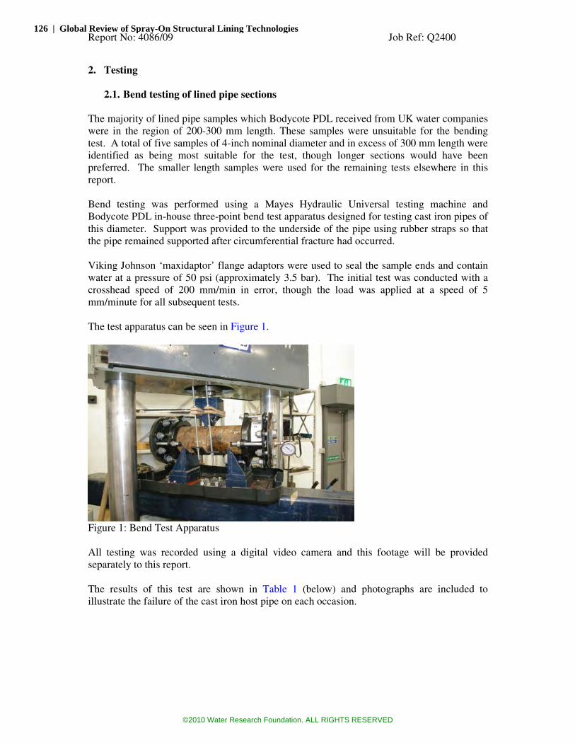
Report No: 4086/09 Job Ref: Q2400
2. Testing
2.1. Bend testing of lined pipe sections
The majority of lined pipe samples which Bodycote PDL received from UK water companies
were in the region of 200-300 mm length. These samples were unsuitable for the bending
test. A total of five samples of 4-inch nominal diameter and in excess of 300 mm length were
identified as being most suitable for the test, though longer sections would have been
preferred. The smaller length samples were used for the remaining tests elsewhere in this
report.
Bend testing was performed using a Mayes Hydraulic Universal testing machine and
Bodycote PDL in-house three-point bend test apparatus designed for testing cast iron pipes of
this diameter. Support was provided to the underside of the pipe using rubber straps so that
the pipe remained supported after circumferential fracture had occurred.
Viking Johnson ‘maxidaptor’ flange adaptors were used to seal the sample ends and contain
water at a pressure of 50 psi (approximately 3.5 bar). The initial test was conducted with a
crosshead speed of 200 mm/min in error, though the load was applied at a speed of 5
mm/minute for all subsequent tests.
The test apparatus can be seen in Figure 1.
Figure 1: Bend Test Apparatus
All testing was recorded using a digital video camera and this footage will be provided
separately to this report.
The results of this test are shown in Table 1 (below) and photographs are included to
illustrate the failure of the cast iron host pipe on each occasion.
126 | Global Review of Spray-On Structural Lining Technologies
©2010 Water Research Foundation. ALL RIGHTS RESERVED

Report No: 4086/09 Job Ref: Q2400
Sample ID
Initial Internal
Pressure (psi)
Test speed
(mm/min) Leakage Damage to lining
6216-11 50 200 Immediate pressure release on failure of iron No rupture or damage caused to lining
6216-10 50 5 Immediate pressure release on failure of iron No rupture or damage caused to lining
6216-1A 50 5 Immediate pressure release on failure of iron No rupture or damage caused to lining
6216-1B 50 5 Immediate pressure release on failure of iron No rupture or damage caused to lining
6234-2 50 5 Immediate pressure release on failure of iron No rupture or damage caused to lining Table 1: Results of bend testing
In all cases the internal pressure was released immediately upon failure of the iron host pipe;
however, this was never as a result of lining rupture. Due to the low level of adhesion
between lining and host pipe, when the samples were deflected the lining ‘slid’ within the
iron (away from the pipe ends) resulting in no localised yielding or damage to the lining, but
leakage of water through the annular gap between lining and host pipe. This can be clearly
seen in the video footage of testing.
The nature of failures for the five samples tested can be seen in Figures 2-6.
Figure 2: 6216-11 Failure
Figure 3: 6216-10 Failure
Appendix B | 127
©2010 Water Research Foundation. ALL RIGHTS RESERVED

Report No: 4086/09 Job Ref: Q2400
Figure 4: 6216-1A Failure
Figure 5: 6216-1B Failure
Figure 6: 6234-2 Failure
Failure of the sample 6216-10 did not occur entirely around the artificially introduced
circumferential groove as there was an area of deep corrosion penetration present which
caused a sizeable fragment of iron pipe wall to be released as can be seen in the failure
picture (Figure 3) above. This did not result in damage of the PU lining material.
After testing of the sample 6216-11 further deflection was applied in order to illustrate the
effect of ‘lining slip’ further and can be seen in Figure 7. It should be noted that with
deflection of this extent, tearing of the lining did eventually result and is shown in Figure 9.
128 | Global Review of Spray-On Structural Lining Technologies
©2010 Water Research Foundation. ALL RIGHTS RESERVED

Report No: 4086/09 Job Ref: Q2400
Figure 7: Greater degree of deflection applied to illustrate ‘sliding’ of lining within iron
Figure 8: Illustrating extent of deflection required to cause tearing of lining
Figure 9: Illustrating tear (at crown of pipe during testing)
Appendix B | 129
©2010 Water Research Foundation. ALL RIGHTS RESERVED

Report No: 4086/09 Job Ref: Q2400
2.2. Lining thickness evaluation
2.2.1. Sample Batch 1 (sample prefix #6205)
The samples supplied for testing were all produced to have nominal lining thickness of 2 mm.
Thickness Variation (circumferential)
0
1
2
3
4
5
6
1 2 3 4 5 6 7 8
1
2
3
4
5
6
7
Figure 10: Circumferential thickness measurements from sample Batch 1
Circumferential lining thickness was found to be relatively consistent (~2 mm) in this batch
of samples except the sample 6205-1. 6205-1 showed significant increase in lining thickness
at base of pipe - ‘slump’. This lining had possibly not cured rapidly enough. Figure 11
illustrates this.
Figure 11: Increase in lining thickness at pipe invert
130 | Global Review of Spray-On Structural Lining Technologies
©2010 Water Research Foundation. ALL RIGHTS RESERVED
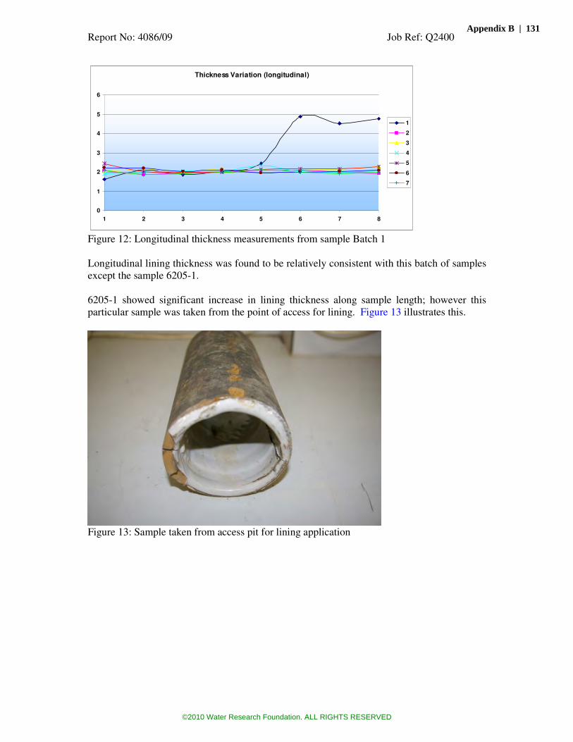
Report No: 4086/09 Job Ref: Q2400
Thickness Variation (longitudinal)
0
1
2
3
4
5
6
1 2 3 4 5 6 7 8
1
2
3
4
5
6
7
Figure 12: Longitudinal thickness measurements from sample Batch 1
Longitudinal lining thickness was found to be relatively consistent with this batch of samples
except the sample 6205-1.
6205-1 showed significant increase in lining thickness along sample length; however this
particular sample was taken from the point of access for lining. Figure 13 illustrates this.
Figure 13: Sample taken from access pit for lining application
Appendix B | 131
©2010 Water Research Foundation. ALL RIGHTS RESERVED

Report No: 4086/09 Job Ref: Q2400
2.2.2. Sample Batch 2 (sample prefix #6216)
The samples supplied for testing were all produced to have nominal lining thickness of 2 mm.
Thickness Variaton (cirmumferential)
0
1
2
3
4
5
6
1 2 3 4 5 6 7 8
3
4
5
6
7
8
9
Figure 14: Circumferential thickness measurements from sample Batch 2
Lining thickness variation was greater among the second sample batch (#6126) than the
previous batch, although generally was not far below the specified thickness of 2 mm.
Thickness Variation (longitudinal)
0
1
2
3
4
5
6
1 2 3 4 5 6 7 8
3
4
5
6
7
8
9
Figure 15: Longitudinal thickness measurements from sample Batch 2
132 | Global Review of Spray-On Structural Lining Technologies
©2010 Water Research Foundation. ALL RIGHTS RESERVED

Report No: 4086/09 Job Ref: Q2400
2.3. Adhesion testing
It was observed that the lining was not well adhered to the pipe samples. A distinct gap could
be seen between the lining and the pipe at freshly cut pipe ends. When the pipe was cut in the
axial direction, the lining became separated from the pipe with absolute minimal effort. It
was therefore considered that determination of adhesion of the lining to the pipe was not
worthwhile because adhesion was clearly negligible.
Figure 16: Example of lining separated from host pipe
Appendix B | 133
©2010 Water Research Foundation. ALL RIGHTS RESERVED

Report No: 4086/09 Job Ref: Q2400
2.4. Differential scanning calorimetry (DSC)
It was not known in advance whether DSC testing would be appropriate for this type of lining
material, but because the technique is considered to be a useful technique for finding both
melting and glass transitions in polymers it was considered to be worthwhile. As expected,
there was no melting transition for this material, but there did appear to be a glass transition
(Tg) around 65ºC. With materials that exhibit such a transition, this may indicate a degree of
cure (crosslinking) of the material and multiple runs can demonstrate a change in the level of
cure during the testing process. This is often used to ensure adequate cure of factory applied
coatings such as epoxy for example. In this case, two identical runs of the instrument were
carried out with the same sample in each case from ambient to 200ºC at a heating rate of 20ºC
per minute, with the same rate of cooling between each run. The results are tabulated below.
Sample Testing Date
Mass of the sample (mg)
Tg1 (ºC)
Tg2 (ºC)
6205-1 12/05/2009 14.9 67.3 110.2
6205-2 13/05/2009 14.7 64.7 102.2
6205-3 12/05/2009 15.1 62.6 96.1
6205-4 13/05/2009 15.3 68.1 104.3
6205-5 12/05/2009 15.2 63.3 94.7
6205-6 13/05/2009 14.5 57.3 112.1
6205-7 15/05/2009 15.7 63.9 99.6
6216-3 10/06/2009 15.3 70.4 75.44
6216-4 10/06/2009 15.1 67.2 n/a
6216-5 10/06/2009 15.1 72.4 81.31
6216-6 10/06/2009 14.9 n/a n/a
6216-7 11/06/2009 15.2 65.09 n/a
6216-8 11/06/2009 15.2 59.13 n/a
6216-9 11/06/2009 14.8 66.5 71.26
Table 2 – Summary of DSC results
It was observed from the DSC testing results for samples from batch #6205 that there is a
significant increase in the second glass transition temperature (Tg2) for all samples. This
might be due to the fact that lining materials were partially cured resulting in a shift of glass
transition temperature.
Where Tg2 could be determined, tests conducted for sample batch #6216 showed a less
significant shift in second glass transition temperature than those samples from batch #6205.
In the case of samples 6216-4, 6216-7 and 6216-8 a second glass transition temperature could
not be determined.
Sample 6216-6 proved difficult to determine the first glass transition also, as the transition
temperature was masked by a small endothermic reaction. This is may be due to slight
contamination present in the sample.
134 | Global Review of Spray-On Structural Lining Technologies
©2010 Water Research Foundation. ALL RIGHTS RESERVED
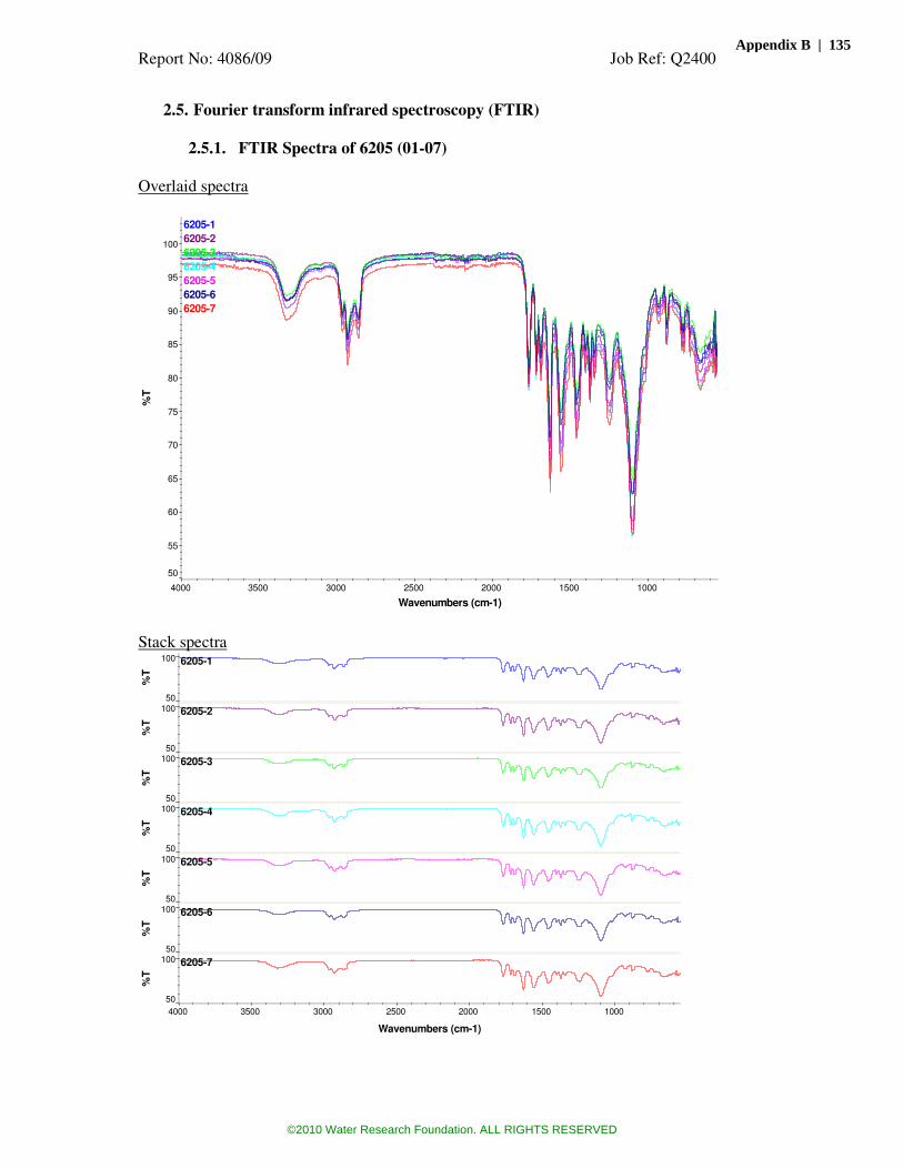
Report No: 4086/09 Job Ref: Q2400
2.5. Fourier transform infrared spectroscopy (FTIR)
2.5.1. FTIR Spectra of 6205 (01-07)
Overlaid spectra
6205-1
6205-2
6205-3
6205-4
6205-5
6205-6
6205-7
50
55
60
65
70
75
80
85
90
95
100
%T
1000 1500 2000 2500 3000 3500 4000
Wavenumbers (cm-1)
Stack spectra 6205-1
50
100
%T
6205-2
50
100
%T
6205-3
50
100
%T
6205-4
50
100
%T
6205-5
50
100
%T
6205-6
50
100
%T
6205-7
50
100
%T
1000 1500 2000 2500 3000 3500 4000
Wavenumbers (cm-1)
Appendix B | 135
©2010 Water Research Foundation. ALL RIGHTS RESERVED

Report No: 4086/09 Job Ref: Q2400
2.5.2. FTIR Spectra of 6216 (03-09)
Overlaid spectra 6216-3
6216-4
6216-5
6216-6
6216-7
6216-8
6216-9
50
55
60
65
70
75
80
85
90
95
100
%T
1000 1500 2000 2500 3000 3500 4000
Wav enumbers (cm-1)
Stack spectra 6216-3
50
100
%T
6216-4
50
100
%T
6216-5
50
100
%T
6216-6
50
100
%T
6216-7
50
100
%T
6216-8
50
100
%T
6216-9
50
100
%T
1000 1500 2000 2500 3000 3500 4000
Wavenumbers (cm-1)
The Fourier Transform Infrared (FTIR) analysis did not show any significant difference
between lining materials. This implies that there was not any significant chemical difference
in molecular structure of lining materials.
136 | Global Review of Spray-On Structural Lining Technologies
©2010 Water Research Foundation. ALL RIGHTS RESERVED

Report No: 4086/09 Job Ref: Q2400
2.6. Short-term bend testing of lining
Three point bend testing was conducted to determine short term modulus using machined
specimens of nominal values of 15mm width and 2mm thickness. Support span was 40mm
and test speed 10mm/min.
Sample ID
Mean Short-term Modulus (Mpa)
6205-1 925
6205-2 707
6205-3 800
6205-4 707
6205-5 670
6205-6 779
6205-7 658
6216-3 450
6216-4 562
6216-5 684
6216-6 525
6216-7 455
6216-8 411
6216-9 702
Table 3 – Short term flexural modulus results
These results are an indication of the stiffness of the material and there does appear to be
some fluctuation in the results obtained from a minimum of 411MPa to a maximum of
925MPa.
Appendix B | 137
©2010 Water Research Foundation. ALL RIGHTS RESERVED

Report No: 4086/09 Job Ref: Q2400
2.7. Long-term (creep) bend testing of lining
LONG-TERM WET-CREEP TESTING OF YORKSHIRE
WATER PU LINER 6205 AFTER 1000 HOURS
0.0001
0.001
0.01
0.1
1
10
100
0.1 1 10 100 1000 10000 100000 1000000
Time (hours)
Mo
du
lus
(GP
a)
50 YEARSAverage Predicted 50-year Modulus = 3MPa
LONG-TERM WET-CREEP TESTING OF YORKSHIRE
WATER PU LINER 6216 AFTER 1000 HOURS
0.0001
0.001
0.01
0.1
1
10
100
0.1 1 10 100 1000 10000 100000 1000000
Time (hours)
Mo
du
lus
(GP
a)
50 YEARSAverage Predicted 50-year Modulus = 7MPa
These tests involve the deflection of a flat bar sample in the flexural test with a constant
applied stress, with the sample encapsulated in an environment of water. The results indicate
the level of creep in the samples which are likely to be influenced by absorption of water to
some extent. Overall, the reduction in stiffness is considerable for this material, with modulus
around 500MPa initially changing to around 50MPa at 350 hours and 7MPa at 50 years. This
may be significant for the long-term performance of a semi-structural lining.
138 | Global Review of Spray-On Structural Lining Technologies
©2010 Water Research Foundation. ALL RIGHTS RESERVED

Report No: 4086/09 Job Ref: Q2400
2.8. Charpy impact testing to determine fracture toughness
Charpy impact testing was conducted using machined specimens of nominal width 10mm and
thickness 2mm. Support span was 40mm and test temperature 0ºC.
Sample ID
Mean Impact Toughness ‘Gc’ (kJ/m
2)
6205-2 2.7
6205-4 2.7
6205-5 2.5
6205-6 2.4
6205-7 2.9
6216-3 4.9
6216-4 3.9
6216-5 2.9
6216-6 2.6
6216-7 2.8
6216-8 3.3
Comparative impact toughness values for PE80 would be 14kJ/m
2 and 60kJ/m
2 for PE100,
which indicates that this material is far more prone to rapid crack propagation than PE.
Appendix B | 139
©2010 Water Research Foundation. ALL RIGHTS RESERVED
Report No: 4086/09 Job Ref: Q2400
3. Conclusions
Bend testing of lined pipe sections
• Fracture of pipe did not result in localised damage or yielding of lining.
• Low adhesion of lining to pipe allowed lining ‘slip’ during sample deflection.
• Water tracked through the annulus allowing pressure release following failure of host
pipe. This is probably not representative of an in-service scenario as providing that
the lining were to be continuous and bridged any gaps/joints then water would be
unable to enter the annulus, even following circumferential failure of the host pipe.
• If the lining was not continuous then the potential to leak following the mechanism
seen in this testing does exist.
Lining thickness
• Samples from batch #6205 showed good consistency of lining thickness.
• Samples from batch #6216 exhibited greater variation in lining thickness, though
generally were not thinner than 2mm.
Adhesion
• Found to be negligible. This is illustrated by both release of the lining from the iron
upon sectioning of specimens, and also by the ‘slip’ seen during bend testing of full
pipe sections.
DSC
• This technique may be useful for evaluating cure of the lining, but early results are
inconclusive.
• Glass transition temperatures (Tg) were reasonably consistent, but it was not always
possible to determine Tg.
FTIR
• FTIR results showed that the chemical constitution of all samples was consistent.
Short-term flexural modulus
• The initial stiffness of the material was found to reasonably consistent with values of
modulus within the range 400-900MPa.
Long-term flexural modulus
• The material was found to suffer a high degree of creep in long term tests in water,
which may be significantly influenced by absorption of water and could be
detrimental to the long term performance of a semi-structural lining.
Charpy impact testing
• Samples subjected to a test specified in the UK for PE pipe materials indicated
consistently lower values for the PUHB lining material.
140 | Global Review of Spray-On Structural Lining Technologies
©2010 Water Research Foundation. ALL RIGHTS RESERVED
Report No: 4086/09 Job Ref: Q2400
Appendix A
BODYCOTE TESTING LIMITED STANDARD CONDITIONS OF CONTRACT (“the Conditions”)
1. Interpretation In the Conditions the following expressions shall (unless the context requires) have the following meanings:
“Client” means the person, firm or company to whom a Quotation is addressed or for whom a Test or any Services is carried out;
“Confidential all information in respect of the business of the Company including but not Information” limited to know-how or other matters connected with the Services and information concerning the Company’s
relationships with actual or potential clients, customers or suppliers and the needs and
requirements of the Company and any other information which if disclosed will be liable to cause harm to the Company;
“Company” means Bodycote Testing Limited or named operating unit thereof;
“Contract” means the contract for the supply of Services of which the Conditions form part; “Losses” means all losses, liabilities, claims, costs, expenses, damages, actions, awards, penalties
and/or fines, obligations and also includes all losses, liabilities, costs and expenses in
relation to or resulting from any demands, claims or proceedings;
“Price” means the price stated in the Quotation, or otherwise agreed with the Client together with all other sums due pursuant to the Conditions;
“Quotation” means the Company’s quotation (whether written or oral) of which the Conditions form part;
“Report” means any test certificate, technical report, non-destructive test or inspection record, drawing, spreadsheet, recommendation, advice or the like issued by the Company in
respect of a Service;
“Sample” means any material, item, product or compound supplied by the Client to form the basis of a Test;
“Services” means the services specified in the Quotation; and
“Test” means any testing, analysis, assay, inspection or the like specified in a Quotation.
2. Quotation
2.1 The Quotation constitutes an offer by the Company to provide Services and/or
carry out a Test subject to the Conditions and is open for acceptance for seven days
only from the date of the Quotation unless previously withdrawn by the Company. Acceptance is based on the receipt of an instruction in writing or receipt of the Sample
by the Company.
2.2 Except in accordance with the Conditions no variation of the Contract will be
accepted unless agreed in writing by the Company.
2.3 The Quotation shall prevail over any terms or conditions (whether or not inconsistent with the Quotation and/or the Conditions) contained or referred to in any
correspondence, order, documentation submitted by the Client or elsewhere. Further,
no condition, statement or representation contained in any advertisement or brochure or in any trade or promotional circular or other literature, nor the terms or conditions of
any trade association or other body, or which would or might but for this sub-
paragraph be implied or incorporated by custom or trade, usage, negotiations, course of dealing or otherwise shall be deemed to be incorporated in the Contract and all of the
same are hereby expressly excluded from the Contract.
3. Price
3.1 The Price is based on information available to the Company at the date of the
Quotation. If during the period of the Contract there shall be any variation in the cost of materials, labour or otherwise to the Company, the Price may, in the absolute
discretion of the Company, be adjusted to take account of such variation.
3.2 In addition to the amount specified in the Quotation the following shall be payable
if appropriate:
3.2.1 any applicable value added tax;
3.2.2 package, insurance, freight, travel costs, bank charges, Sample destruction
costs, storage charges and disbursements incurred on behalf of the Client,
whether on the Company’s premises or elsewhere, and to include storage charges on the Company’s premises, if any Sample or materials supplied by
the Client are not removed within seven days of the date of notification to the
Client that they are ready for collection;
3.2.3 insurance incurred by the Company, in its absolute discretion, in respect of
any property belonging to the Client in the possession of the Company;
3.2.4 with prior notice, the cost of all sub-contractors employed by the Company
unless included in the Quotation;
3.2.5 any additional costs incurred by the Company in accordance with the
Conditions; and
3.2.6 any special standards or specifications required for the performance of the
Service.
4. Payment
4.1 The Price shall be paid to the Company in full, in cleared funds, without any deduction, set-off or counterclaim within thirty days of the date of the Company’s
invoice. Time of payment is of the essence to the Contract. In default of payment
within the thirty days, the Company may: suspend any further Services being carried out for the Client; withhold the provision of Reports; alter or withdraw credit terms;
and amend terms, prices or service levels . The amount outstanding from time to time shall bear interest (both before and after any judgment) at the rate of 4% per annum above the Royal Bank of Scotland plc base rate from time to time from the due date for
payment until payment in full is made.
4.2 All payments due to the Company shall be payable within the specified time irrespective of whether or not the Client has recovered payment from a third party and,
for the avoidance of doubt, but without prejudice to the generality of the foregoing, this
includes payments of fees due to the Company acting as experts or as expert witnesses
when instructed by solicitors acting for a party to a dispute.
4.3 If, in the Company’s view, the Client’s credit-worthiness deteriorates before completion of the Service, the Company may require payment in full or in part of the
Price prior to completion, or the provision of security for payment by the Client in such
form as is acceptable to the Company.
4.4 The Company has a general lien on all the Client’s property in the Company’s
possession in satisfaction of any amount owed by the Client to the Company under the
Contract, and may deal with it as it sees fit.
5. Execution of Services
5.1 Tests shall be carried out singly unless prior written instructions from the Client are
received for replicates or unless the Company considers replicates are necessary or desirable. The Company reserves the right to charge for replicates even if the original
result is confirmed.
5.2 The Client shall supply as much information as possible about each Sample and/or
Service requirement in order to assist in achieving an efficient service. Where
information relating to the Sample and/or the Service requirements is incorrect and the Company is involved in additional work, the Company reserves the right to charge for
such additional work.
5.3 Unless specific prior instructions in writing are received by the Company any Test
shall be carried out on the Sample in the state in which the sample is received. The
Company reserves the right to charge for any work required to be carried out to the
Sample prior to the performance of any Service.
5.4 Methods of carrying out the Service and providing the Report shall be at the sole
discretion of the Company unless prior instruction in writing is received from the Client specifying a particular procedure. Charges for such special procedures will be
agreed between the Company and the Client prior to carrying out the Service.
5.5 A general description of the method used in the performance of the Service shall be
given verbally on request. Where written descriptions of detailed procedures are
requested, whether as part of the Report or issued separately, the Company reserves the right to make an additional charge. If the method referenced in the Report represents
the end product of development work carried out at the Company’s expense, the
method shall only be revealed at the discretion of the Company.
5.6 The Company may, at its sole discretion, undertake to give priority in carrying out
a particular Service. A surcharge may be imposed by the Company for the carrying out of priority work. Details of these arrangements will be issued by the Company on
request.
6. Samples subject of legal proceedings
If the Sample is, or is potentially, the subject of legal proceedings, this fact must be notified to the Company in writing before the Service is carried out. If that fact is not
disclosed to the Company at that stage, the Company may not, in its absolute
discretion, be prepared to provide expert testimony.
7. Disclaimer/Liability
7.1 The following provisions of this Condition 7 set out the entire liability of the
Company, its employees, agents and sub-contractors to the Client howsoever arising.
7.2 The Company does not exclude its liability (if any) to the Client:
7.2.1 for breach of the Company’s obligations arising under section 12 Sale of
Goods Act 1979 or section 2 of the Supply of Goods and Services Act 1982;
7.2.2 for personal injury or death resulting from the Company’s negligence;
7.2.3 under section 2(3) of the Consumer Protection Act 1987;
7.2.4 for any matter which it would be illegal for the Seller to exclude or to
attempt to exclude its liability; or
7.2.5 for fraud or fraudulent misrepresentation.
7.3 Except as provided in Condition 7.2 the Company shall not be liable to the Client
whether in contract, tort (including negligence), breach of statutory duty or otherwise for any loss of profit, loss of business, loss of market, loss of contract, damage to
goodwill, loss of anticipated savings, loss of revenue, loss or damage incurred as a
result of third party claims or any indirect or consequential loss howsoever caused.
7.4 Subject to Condition 7.2 and Condition 7.3, the Company’s aggregate liability
under the Contract (whether in contract, tort (including negligence), breach of statutory duty or otherwise) arising out of or in connection with the performance or
contemplated performance of the Contract or any delay in performance or failure to
perform by the Company or otherwise howsoever arising shall be limited to the Price.
7.5 Subject to the other provisions of the Conditions any claim by the Client against the
Company shall be made in writing and notified to the Company within 365 days of
completion of the Services under the Contract by the Company to the Client.
7.6 All Services are undertaken in good faith, to a reasonable standard of care and on a
confidential basis. Reports are issued on the basis of information known to the
Company at the time that the Services are carried out. Although the Company will use all reasonable endeavours to ensure accuracy, the Services depend, inter alia, on the effective co-operation of the Client, its staff and on the information submitted to the
Company. Save as required by law, no representation or warranty, whether express or
implied or otherwise as to the accuracy of a Report is given by the Company. In
consequence, all Reports are prepared on the basis that:
7.6.1 there is no responsibility to any person or body other than the Client;
7.6.2 they are not carried out for any particular purpose and no statement is to be deemed, in any circumstances to be or give rise to a representation,
undertaking, warranty or contractual condition unless specifically stated;
7.6.3 they are determined solely by the professional analysis undertaken by the Company’s staff on each individual Contract and any forecasts by the
Company of the results is an estimate only;
7.6.4 the Company is entitled to be paid the Price irrespective of the results or
conclusions reached in the Report;
7.6.5 the results of the Services shall address the items and information submitted
only and are not to be regarded as representative of any larger population
from which the Sample was taken; and
7.6.6 the results are final and approved by the Company. The Company shall be
under no liability where the Client has acted on preliminary, unapproved
results or advice.
7.7 All time limits, if any, for the provision of the Services or Tests are estimates and
no undertaking is given to carry out the Services or to despatch any Report within any
period of time.
7.8 The Company shall not be liable to the Client or be deemed to be in breach of the Contract by reason of any delay in performing, or any failure to perform, any of the
Company's obligations in relation to the Services, if the delay or failure was due to any
cause beyond the Company's reasonable control. Without prejudice to the generality of the foregoing, causes beyond the Company's reasonable control shall include an Act of
God, explosion, adverse weather conditions, flood, earthquake, tempest, fire, accident,
war or threat of war, acts or threats of terrorism, sabotage, insurrection, riot, civil disturbance, requisition, acts, restrictions, regulations, bye-laws, prohibitions or measures of any kind on the part of the governmental, parliamentary or local authority,
import or export regulations or embargoes, strikes, lock-outs or other industrial actions
or trade disputes (whether involving employees of the Company or of a third party), difficulties in obtaining raw materials, labour, fuel, parts or machinery, power failure
or breakdown in machinery.
7.9 Except where the Services are provided to a person who deals as a consumer (within the meaning of the Unfair Contract Terms Act 1977), all warranties, conditions
or other terms express or implied, statutory, customary or otherwise are excluded to the
fullest extent permitted by law.
7.10 Where the Services are provided under a consumer transaction (as defined by the
Consumer Transactions (Restrictions on Statements) Order 1976 as amended) the
statutory rights of the Client are not affected by the Conditions.
7.11 The Client acknowledges that the above provisions of this Condition 7 are reasonable and reflected in the price which would be higher without those provisions
and the Client will accept such risk and/or insure accordingly.
8. Obligations of Client
8.1 The Client shall provide with each Sample and/or Service a unique purchase order or unique reference or unique authorisation with sufficient detail to allow the Company
to identify each Sample (if applicable) and relate it to a specific Quotation and Service
and the Company shall be entitled in good faith to rely upon such purchase order or
reference provided to carry out the Service.
8.2 The Client may reproduce or replicate any Report in the form provided by the Company but shall not, without the written consent of the Company, reproduce or
replicate any Report which has been modified from the form provided by the
Company.
8.3 The Client shall be bound to inform the Company in writing prior to the Company
carrying out any Service on a Sample that is of a dangerous or unstable nature and provide instruction on the safe handling of the Sample. The Client shall indemnify the
Company from and against all Losses suffered by the Company, including, without
prejudice to the generality of the foregoing, all damage to the Company’s property and all claims in respect of injury to or deaths of any of the Company’s employees, sub-contractors or agents or of any third party, directly or indirectly arising from or in
connection with the failure of the Client to inform the Company of the dangerous or
unstable nature of a Sample and/or to provide adequate instruction on the safe handling of the Sample. Where the Client informs the Company that a Sample is of a dangerous
or unstable nature, the Company may, in its absolute discretion, elect not to carry out
the Service and to terminate the Contract whereupon the provisions of Condition 12.3 will apply, save that the Company shall have no liability for its termination of the
Contract.
8.4 The Client agrees to indemnify, keep indemnified and hold harmless the Company
from and against all Losses which the Company may suffer or incur arising out of or as
a result of any breach or negligent performance or failure in performance by the Client of the terms of the Contract or breach of any law or any claim threatened or made
against the Company by any third party arising out of the Services or out of any delay
in performing or failure to perform the Services.
8.5 Where Services are provided at the premises of the Client, the Client will be
responsible for providing a safe system of work for the Company and its employees
while providing the Service and the Client shall be responsible for all costs necessarily required in discharging this obligation and shall indemnify the Company, its employees, sub-contractors and agents in respect of all Losses suffered as a result of
any breach by the Client hereof.
9. Risk and property in relation to Tests
9.1 Unless stated in the Quotation, Samples are and remain at all times (including,
without limitation, whilst at the Company's works and during transportation to and
from the Company's works) at the entire risk of the Client who shall be responsible for effecting and maintaining its own insurance cover in relation thereto, it being hereby
acknowledged by the Client that the charges of the Company do not include insurance.
9.2 Unless expressly stated to the contrary in the Contract, Samples of a stable nature
shall be retained for three months from the date of their receipt and then destroyed.
9.3 Where Samples are, in the sole opinion of the Company, too bulky or too unstable
to allow storage time of more than one month, it will be at the absolute discretion of
the Company as to the length of time such samples are kept before being destroyed.
9.4 Samples shall be returned to the Client only if prior instructions in writing in that
regard are received by the Company and the Client shall be charged for all costs
associated therewith (including carriage).
10. Ownership, copyright and patents in relation to Services
10.1 All copyright in records, scientific documentary, primary data or electronic means
of handling data produced during any Service shall belong to and remain the property
of the Company unless otherwise agreed as part of the Contract.
10.2 Ownership and copyright in the Report shall remain with the Company until the Client has discharged all its obligations under the Contract, including payment of the
Price, whereupon the title, ownership and copyright shall pass to the Client unless the
Company is forced to part with any such report, or information of any nature, to any
body exercising its statutory powers.
10.3 The Client hereby warrants that it will not use the Report or any other reports,
results, or information supplied by the Company for the purposes of advertisement or
publication to third parties. Any such issue of the Report or other reports, results or information is permitted under the Contract only with the prior written consent of the
Company who shall have the right to increase the Price where it consents to such
advertisement and/or publication.
10.4 The Client hereby undertakes to abide by any regulations imposed by
Certification Authorities, Standard Owners, Accreditation Bodies or the Department of Trade and Industry of Her Majesty’s Government relating to marks, emblems or logos
attached to the Reports or any other documents issued under the Service.
10.5 All inventions arising from the Contract and any applications for patents or similar protection, whether in the United Kingdom or elsewhere shall be the property
of the Client (once all payments due to the Company under contract have been
discharged), but the Company is hereby granted an irrevocable royalty free licence, with the right to sub-licence, to apply them or any information gained to work outside
the specific field in which the development for the Client took place.
11. Sub-contracting and assignment
11.1 Unless otherwise restricted by the terms of the Contract and/or obligations under
any accreditation or governing approval, the Company shall be entitled, in its absolute
discretion, to sub-contract the whole of or any part of the Service.
11.2 The Company may assign, delegate, licence or hold on trust, all or any part of its
rights or obligations under the Contract.
11.3 The Contract is personal to the Client which may not assign, delegate, licence,
hold on trust or sub-contract all or any of its rights or obligations under the Contract
without the Company’s prior written consent.
12. Termination
12.1 The Client shall not terminate the Contract without the written consent of the
Company which may be subject to such terms, as in the Company’s absolute discretion, recompense the Company for all loss it may suffer as a result of
termination.
12.2 The Company may terminate the Contract and any other contract with the Client
forthwith, without prejudice to any other right or remedy available to the Company and
without the Company incurring any liability to the Client, in the following circumstances:
12.2.1 if the Client shall commit a breach of any terms of the Contract or any other contract with the Company unless such breach is capable of remedy and the
Client has failed to comply with a notice requiring remedy within the period
specified in the said notice;
12.2.2 if the Client fails to make payment of the Price within the specified time;
12.2.3 the Client makes any voluntary arrangement with its creditors or becomes subject to an administration order or (being an individual or firm) becomes
bankrupt or (being a company) goes into liquidation (otherwise than for the
purposes of amalgamation or reconstruction) or ceases or suspends payment of any of its debts or is unable to pay its debts as they fall due within the
meaning of section 123 of the Insolvency Act 1986;
12.2.4 an encumbrancer takes possession, or a receiver or administrator is
appointed, over any of the property or assets of the Client;
12.2.5 the Client ceases, or threatens to cease, to carry on business;
12.2.6 the Company reasonably apprehends that any of the events mentioned at
Conditions 12.2.3, 12.2.4 or 12.2.5 above is about to occur in relation to the
Client and notifies the Client accordingly; and
12.2.7 as provided in Condition 8.3.
12.3 Notwithstanding that the Company terminates the Contract, this shall be without
prejudice to the accrued rights and remedies of the parties prior to termination of the
Contract and any rights or remedies under the Conditions, which shall remain in force, including the right to suspend all further Services to be made under any other contract
with the Client (and in such event the Client shall not be released from any of its
obligations to the Company under any other contract) and the right for the Company to receive full compensation for its loss under the Contract or any other contract with the
Client.
12.4 On termination of the Contract pursuant to Condition 12.2, any indebtedness of
the Client to the Company shall become immediately due and payable.
13. Confidentiality
13.1 All Confidential Information shall be kept by the Client in the strictest confidence.
Save for the purposes of fulfilling its obligations under the Contract, the Client shall
not, without the prior written consent of the Company, disclose, divulge or grant access to the Confidential Information which it has received and shall not permit any of its employees, agents or officers to disclose, divulge or grant access to such
Confidential Information.
13.2 Notwithstanding Condition 13.1, the Client may disclose Confidential Information
which it has received if:
13.2.1 it is required to do so by any governmental, local government or regulatory
authority or by law (but then only to the extent it is strictly required to do
so);
13.2.2 it is strictly necessary for the purpose only of obtaining professional advice
in relation to the Contract;
13.2.3 it is already known to the Client prior to the time of disclosure by the
Company (where the Client can prove the same with documentary evidence);
or
13.2.3 it is information which subsequently becomes public knowledge other than
by breach of the Contract by the Client.
13.3 The obligations of the parties under this Condition 13 shall continue to apply
without limit of time.
14. General
14.1 Each right or remedy of the Company under any Contract is without prejudice to
any other right or remedy of the Company under this or any other Contract.
14.2 Nothing in the Conditions shall create or be deemed to create a partnership
between the parties.
14.3 The Conditions, the Quotation and the Contract contain all the provisions which
the parties have agreed in relation to the subject matter of the Contract and supersede
any prior written or oral agreements, representations or understandings between the parties. The Client agrees that it has not been induced to enter into the Conditions or
the Contract by a statement or promise which they do not contain save that the
Conditions shall not exclude any liability which the Company would otherwise have to
the Client in respect of any statements made fraudulently by the Company.
14.6 In the event of one or more of the provisions of the Conditions being held by a competent authority to be invalid, illegal, or unenforceable, in whole or in part, the
validity, legality or enforceability of the remaining provisions of the Conditions and
the remainder of the provision in question shall not be affected thereby.
14.7 All notices to be served by one party on the other must be in writing and shall be
deemed duly delivered or served at the time of service if delivered personally and forty
eight hours after posting if posted by first class or airmail pre-paid post in each case to the registered address, if applicable, or if not applicable the last known address of the
other party.
14.8 No failure or delay by the Company to exercise any right, power or remedy will
operate as a waiver of it nor will any partial exercise preclude any further exercise of
the same or of some other right, power or remedy.
14.9 For the purpose of the Contracts (Rights of Third Parties) Act 1999, the Quotation
and the Conditions do not and are not intended to give any rights or any right to
enforce any of its provisions to any person who is not a party to it.
14.10 The Quotation, Conditions and the Contract shall be governed by and construed
in accordance with the laws of England and Wales and the Client submits to the
exclusive jurisdiction of the English Courts.
Appendix B | 141
©2010 Water Research Foundation. ALL RIGHTS RESERVED

©2010 Water Research Foundation. ALL RIGHTS RESERVED

143
Appendix C
South West Water – Procedure for Renovated Mains Disinfection and Clearance
©2010 Water Research Foundation. ALL RIGHTS RESERVED

144 | Global Review of Spray-On Structural Lining Technologies
South West Water
Scientific: Procedure
Renovated Mains Disinfection and Clearance
QSC-003
A. PURPOSE AND SCOPE To describe the disinfection and clearance requirements that apply to the renovation of water mains by the following techniques: pipe bursting, slip lining, close fit lining or spray relining. To ensure that the requirements of Technical Guidance Note No4 and the relevant sections of the Principles of Water Supply Hygiene are met.
B. CONTENTS A. PURPOSE AND SCOPE .......................................................................................... 144 B. CONTENTS .............................................................................................................. 144 C. CHANGES IN THIS DOCUMENT ......................................................................... 144 D. RECORDS / FORMS / LOGS .................................................................................. 144 E. REFERENCES ......................................................................................................... 145 F. PROCEDURE ........................................................................................................... 145
1. Prerequisites ................................................................................................. 145 2. Background Chlorine.................................................................................... 146 3. Temporary Pipework .................................................................................... 146 4. Swabbing of Rehabilitated Section .............................................................. 147 5. Disinfection of Rehabilitated Section ........................................................... 147 6. Clearance Sampling of Rehabilitated Section of Main ................................ 148 7. Introduction to Service ................................................................................. 148
C. CHANGES IN THIS DOCUMENT DESCRIPTION OF CHANGEGeneral update following BJKS review. General update and change pH limits in Section 3. Removal of minimum flushing time from section 5, v.3.1, reinstated
D. RECORDS / FORMS / LOGS REFERENCE TITLE LOCATION Certificates of Analysis Sample Manager
©2010 Water Research Foundation. ALL RIGHTS RESERVED

Appendix C | 145
South West Water
Scientific: Procedure
Renovated Mains Disinfection and Clearance
QSC-003
E. REFERENCES
REFERENCE TITLE LOCATION QSC-001 Water Supply Hygiene Intranet QSC-002 Preparation and Disposal of Chlorine Solutions Intranet QSC-004 New Mains Disinfection and Clearance Intranet QSC-011 On-site Determination of Chlorine Intranet QSC-013 On-site Determination of pH Intranet QSC-014 On-site Determination of Taste and Odour Intranet QSC-015 On site Determination of Conductivity Intranet QSC-016 On-site Determination of Appearance Intranet QSC-018 Labelling of Samples Submitted to the Laboratory Intranet QSC-024 Collection of Samples for Laboratory Analysis Intranet QSC-025 Transport of Samples to the Laboratory Intranet QSC-046 Regulations 31 and 32 Intranet QWD-160 Common Systems Intranet
F. PROCEDURE
1. Prerequisites • Free chlorine residual measured downstream of the working area, is maintained at 0.5
mg/l, or higher, until satisfactory sample results are received and the main has been reintroduced into service. This reduces the need for written clearance prior to introduction to service and allows the dispensation for treating these activities as category 3 under Technical Guidance Note No3.
• The utilisation of online chlorinators is mandatory where a free chlorine residual of 0.5
mg/l cannot be continuously maintained downstream of the working area. If 0.5 mg/l free chlorine is not maintained for the period of the activity then the main cannot be reintroduced to service and the clearance requirements as described in New Mains Disinfection and Clearance ref: QSC-004 apply.
• All coiled pipe or liners are stored in clean conditions with the ends of coiled pipes and
fittings capped securely.
• All temporary hoses, fittings and standpipes comply with Regulation 31 ref: QSC-046, and are securely capped and protected, when not in use. All hoses used for the distribution of potable water are clearly labelled ‘POTABLE WATER ONLY’.
• All temporary bypass hoses and feed hoses for disinfection include non return valves
which comply with Regulation 31.
©2010 Water Research Foundation. ALL RIGHTS RESERVED

146 | Global Review of Spray-On Structural Lining Technologies
South West Water
Scientific: Procedure
Renovated Mains Disinfection and Clearance
QSC-003
• This is a restricted operation within the meaning of the Principles of Water Supply
Hygiene and Technical Guidance Notes. All staff involved with these activities must have written authorisation to undertake restricted operations under Water Supply Hygiene ref: QSC-001
• Duty of Care applies to the disposal of chlorine solutions, which will include the need to
neutralise the chlorine before disposal as described in Preparation and Disposal of Chlorine Solutions ref: QSC-002.
• All rehabilitation techniques must comply with Regulations 31 and 32 ref: QSC-046.
2. Background Chlorine
• At least five days prior to works commencing on-site free chlorine residual is determined in the working area and a continuous proportional dosing on-line chlorinator is installed, if a free chlorine residual of 0.5mg/l, or higher, cannot be maintained.
• Rehabilitation Site Supervisor, Scientist (Potable Water) and Water Distribution
Area Manager will provide advice on the appropriate location of chlorinators if required.
3. Temporary Pipework • Prior to use all temporary pipework is chlorinated using a suitable dosing pump to
achieve 50 mg/l free chlorine residual.
• After a contact period of 30 minutes, temporary pipework is flushed to waste ensuring effective chlorine neutralisation as described in Preparation and Disposal of Chlorine Solutions ref: QSC-002.
• Samples from the pipework are to be tested on-site for;
• pH (6.5 - 9.5) On Site Determination of pH ref: QSC-013 • free and total chlorine (free chlorine > 0.5 mg/l and < 0.2 mg/l difference from
feed water) On Site Determination of Chlorine ref: QSC- 011 • combined chlorine (<0.2 mg/l) On Site Determination of Chlorine ref: QSC- 011 • conductivity (<100uS/cm difference from feed water) On Site Determination of
Conductivity ref: QSC-015 • taste and odour (no unusual taste or odour) On Site Determination of Taste and
Odour ref: QSC - 014 • visual appearance (turbidity < 4 NTU) On Site Determination of Appearance ref:
QSC-016 • On-site test results are recorded on the appropriate site records documentation.
©2010 Water Research Foundation. ALL RIGHTS RESERVED

Appendix C | 147
South West Water
Scientific: Procedure
Renovated Mains Disinfection and Clearance
QSC-003
• Where temporary pipework is greater than 150m and less than 800m in length or is • planned to be deployed for more than 48 hours, additional samples are collected for
coliforms, faecal coliforms, 2 & 3 day TVC (suite CB01) according to Collection of Samples for Laboratory Analysis ref: QSC-024, and labelled and transported to the laboratory as described in Labelling of Samples submitted to the Laboratory for Analysis ref: QSC-018 and Transport of Samples to the Laboratory ref: QSC-025 respectively.
• Where temporary pipework is greater than 800m in length or greater than 2 inch diameter • inform Scientist (Potable Water) who will determine appropriate action.
• If there is any doubt concerning the quality of water via the temporary pipework, or if
any of the on-site tests are not satisfactory, then advice is sought from the appropriate Scientist (Potable Water).
• Provided all the above criteria have been met the temporary pipe is brought into service.
• Results of microbiological analysis are reported to duty Scientist (Potable Water) who
determines appropriate action. Certificates of Analysis are sent to appropriate depot as defined by the Customer ID recorded on the label and stored with the completed package of work.
4. Swabbing of Rehabilitated Section Following completion of the renovation technique the main is swabbed by using a swab previously soaked in 50 mg/l chlorine solution according to Common Systems ref: QWD-160 Water Mains Swabbing.
5. Disinfection of Rehabilitated Section • End caps with suitable feed / drain / sample pipework arrangement are fitted.
• The main is flushed with water by operation of an upstream valve, according to Common Systems ref: QWD- 160.
• The main is charged with a continuous dose of chlorine being presented to the feed water,
by using a suitable dosing pump to achieve 50 mg/l free chlorine.
• The feed is isolated and the main left to stand for a minimum of 30 minutes.
• The free chlorine residual is checked (On-site Determination of Chlorine ref: QSC-011) at all available points to ensure it is still greater than 40 mg/l.
• The residual chlorine is recorded on the appropriate site records documentation.
©2010 Water Research Foundation. ALL RIGHTS RESERVED

148 | Global Review of Spray-On Structural Lining Technologies
South West Water
Scientific: Procedure
Renovated Mains Disinfection and Clearance
QSC-003
• If less than 40mg/l of chlorine is measured following 30 minutes standing refer back
to the appropriate Scientist (Potable Water).
• The main is flushed for a minimum of one hour (Common Systems ref: QWD-160), until the disinfecting chlorine has been removed and the main is completely filled with mains water. This is checked by measuring the free chlorine at the outlet of the main and comparing it with the free chlorine in the feed water, until each are within 0.2 mg/l.
6. Clearance Sampling of Rehabilitated Section of Main
• After the rehabilitated section of main has stood full of mains water for 30 minutes samples are tested on-site for:
• pH (6.5- 9.5) On Site Determination of pH ref: QSC-013 • free and total chlorine (free chlorine > 0.5 mg/l and < 0.2 mg/l difference from
feed water) On Site Determination of Chlorine ref: QSC-011 • combined chlorine < 0.2 mg/l On Site Determination of Chlorine ref: QSC-011. • conductivity (<100uS/cm difference from feed water) On Site Determination of
Conductivity ref: QSC-015 • taste and odour (no unusual taste or odour) On Site Determination of Taste and
Odour ref: QSC - 014 • visual appearance (turbidity ,< 4 NTU). On Site Determination of Appearance
ref: QSC-016 • On-site readings are recorded on the sample label Labelling of Samples submitted
to the Laboratory for Analysis ref: QSC-018 If there is any doubt concerning the quality of water, or if any of the on-site tests are not satisfactory, then seek advice from the appropriate Scientist (Potable Water);
• If on-site tests are satisfactory then samples are collected for coliforms; faecal coliforms;
2 & 3 day TVC (suite CB01) according to Collection of Samples for Laboratory Analysis ref: QSC-024, and labelled and transported to the laboratory as described in Labelling of Samples submitted to the Laboratory for Analysis ref: QSC-018 and Transport of Samples to the Laboratory ref: QSC-025 respectively;
• Results of microbiological analysis are reported to duty Scientist (Potable Water) who
determines appropriate action. Certificates of Analysis are sent to appropriate depot as defined by the Customer ID recorded on the label and stored with the completed package of work.
7. Introduction to Service
Provided all on-site tests are satisfactory the main may be introduced to service.
©2010 Water Research Foundation. ALL RIGHTS RESERVED

149
REFERENCES
Alben, K., A. Bruchet, and E. Shpiert. 1989a. Leachate From Organic Coating Materials Used in Potable Water Distribution Systems. Denver, Colo.: AwwaRF and AWWA.
Alben, Katherine, A. Bruchet, and E. Shpirt. 1989b. Leachate From Organic Coating Materials Used in Potable Water Distribution Systems (Project #105). New York State Department of Health.
Albertsson, A-C, S. Andersson, and S. Karlsson. 1987. The mechanism of the biodegradation of polyethylene. Polymer Degradation and Stability. 18: 73-87.
American Society of Civil Engineers, America’s Infrastructure Report Cart. 2009. ASCE <http://www.asce.org/reportcard/2009/grades.cfm
American Water Works Association. 2008. Spray-Applied In-Place Epoxy Lining of Water Pipelines, 3 In. (75 mm) and Larger – ANSI/AWWA C620-07 (First Edition). Denver, CO: American Water Works Association.
American Water Works Association. 2001. Manual of Water Supply Practices – M28, Second Edition, Rehabilitation of Water Mains. Denver, CO: American Water Works Association.
American Water Works Association. 2008. Spray-Applied In-Place Epoxy Lining of Water Pipelines, 3 In. (75 mm) and Larger – ANSI/AWWA C620-07 (First Edition). Denver, CO: American Water Works Association.
American Water Works Association. 1996. Cement-Mortar Lining of Water Pipelines in Place – 4 In. (100 mm) and Larger – ANSI/AWWA C602-95. Denver, CO: American Water Works Association.
American Water Works Association. 1998. Polyvinyl Chloride (PVC) Pressure Pipe and Fabricated Fittings, 14 In. through 48 In. (350 mm through 1,200 mm), for Water Transmission and Distribution – ANSI/AWWA C905-97. Denver, CO: American Water Works Association.
American Water Works Association. 2007. Polyvinyl Chloride (PVC) Pressure Pipe and Fabricated Fittings, 4 In. through 12 In. (100 mm through 300 mm), for Water Transmission and Distribution – ANSI/AWWA C900-07. Denver, CO: American Water Works Association.
American Water Works Association. 2007. Polyethylene (PE) Pressure Pipe and Fittings, 4 In.. (100 mm) through 63 In. (1,600 mm), for Water Distribution and Transmission – ANSI/AWWA C906-07. Denver, CO: American Water Works Association.
American Water Works Association. 2007. Liquid-Epoxy Coating Systems for the Interior and Exterior of Steel Water Pipelines - ANSI/AWWA C210-07. Denver, CO: American Water Works Association.
American Water Works Association. 2007. Polyurethane Coatings for the Interior and Exterior of Steel Water Pipe and Fittings ANSI/AWWA C22-08. Denver, CO: American Water Works Association.
Amyot, C., M.A. Knight, and B. Garibaldi. 2003. City of Waterloo Case Study-Cement Mortar vs. Epoxy Lining of Water Mains for Improved Water Quality, Proceedings NASTT/ISTT No-Dig’03, Las Vegas, Nev.
©2010 Water Research Foundation. ALL RIGHTS RESERVED

150 | Global Review of Spray-On Structural Lining Technologies
Arevalo, J., J. Taylor, J. Dietz, and G. Mutoti. 2004. Modeling chlorine dissipation in distribution systems. 2004 AWWA Annual Conference Proceedings.; 2004 AWWA Annual Conference, Orlando, Fl.
Argent, C., and D. Norman. 2007. FBE and 3-Layer Polyethylene Coatings for Pipelines: Optimizing Performance and Costs. Journal of Protective Coatings and Linings: 63-77.
ASTM (American Society for Testing and Materials) D790. 2007. Standard Test Methods for Flexural Properties of Unreinforced and Reinforced Plastics and Electrical Insulating Materials, DOI: 10.1520/D0790-07.
ASTM (American Society for Testing and Materials) C497. 2005. Standard Test Methods for Concrete Pipe, Manhole Sections, or Tile, DOI: 10.1520/C0497-05.
ASTM (American Society for Testing and Materials) D4541. 2002 Standard Test Method for Pull-Off Strength of Coatings Using Portable Adhesion Testers, DOI: 10.1520/D4541-02.
ASTM (American Society for Testing and Materials) Standard D2990. 2001. Standard Test Methods for Tensile, Compressive, and Flexural Creep and Creep-Rupture of Plastics, DOI: 10.1520/D2990-01.
ASTM (American Society for Testing and Materials) Standard D6677. 2007. Standard Test Method for Evaluating Adhesion by Knife, DOI: 10.1520/D6677-07.
ASTM (American Society for Testing and Materials) Standard D412. 2006. Standard Test Methods for Vulcanized Rubber and Thermoplastic Elastomers—Tension, DOI: 10.1520/D0412-06AE02.
ANSI/AWWA C222-08, Standard for Polyurethane Coatings for the Interior and Exterior of Steel Water Pipe and Fittings, Denver, Colo.: AWWA.
AWWA C210-07. Standard for Liquid-Epoxy Coating Systems for the Interior and Exterior of Steel Water Pipelines, Denver, Colo.: AWWA.
ANSI/AWWA C602-06, Standard for Cement-Mortar Lining of Water Pipelines in Place―4 In. (100 mm) and Larger, Denver Colo.:AWWA.
Bae, B., J. Jeong, and S. Lee. 2002. The Quantification and Characterization of Endocrine Disruptor Bisphenol-A leaching from Epoxy Resin. Water Science and Technology 46, (11-12), 381-387.
Bakeer R.M., M.E. Barber, J. Taylor, and S. Pechon. 2001. Long-term Buckling Performance of HDPE Liners, Journal of Materials in Civil Eng. 13(3): 176-185.
Barber, M.E., R.M. Bakeer, V.F. Sever, and G.R. Boyd. 2004. Effect of Close-fit Sliplining on the Hydraulic Capacity of a Pressurized Pipeline, Tunnelling and Underground Space Technology, 20 (1): 23-31.
Berend, K., and T. Trouwborst. 1999. Cement Mortar Pipes as Source of Aluminum, Journal AWWA, 91 (7): 91-100.
Bergman, N. 1998. Polyethylene Pipes – a 100 Year Service Life? Proceedings Plastics Pipes X, Goeteborg, Sweden.
Bonds, R.W. 2004. Effect of Chloramines on Ductile-iron Pipe Gaskets of Various Elastomeric Compounds. Journal AWWA. 96(4): 153-158.
Boot, J.C., Z.W. Guan, and I. Toropova. 1996. The Structural Performance of Thin-Walled Polyethylene Pipe Linings for the Renovation of Water Mains, Trenchless Technology Research, 11(1): 37-51.
Boot, J.C. 2005. Preliminary evaluation of the performance eof Copon Hycote 169 HB as a semi-structural sprayed pipe lining for small diameter water mains. E. Wood Ltd.
©2010 Water Research Foundation. ALL RIGHTS RESERVED

References | 151
Boot, J.C. and I. Toropova. 1999. Polyethylene Thin-Walled Linings: Development of Structural Design Guidelines. Trenchless Technology Research, 14(2), 13-28.
Boot, J.C. 2006. Evaluation of the gap spanning capability of Copon Hycote 169 HB semi-structural sprayed pipe linings for small diameter water mains. E. Wood Ltd.
Boot, J.C. 2006. The structural capacity of Copon Hycote 169HB when used as a lining for small (100 mm) diameter potable water pipes. E. Wood Ltd.
Boyd, G.R., H. Wang, M.D. Britton, D.C. Howie, D.J. Wood, J.E. Funk, and M.J. Friedman. 2004a. Intrusion Within a Simulated Water Distribution System due to Hydraulic Transient-Part 1: Description of Test rig and Chemical Tracer Method, ASCE Journal of Environ. Eng., 130 (7): 774-777.
Boyd, G.R., H. Wang, M.D. Britton, D.C. Howie, D.J. Wood, J.E. Funk, and M.J. Friedman. 2004b. Intrusion Within a Simulated Water Distribution System due to Hydraulic Transient-Part 2: Volumetric Method and Comparison of Results, ASCE Journal of Environ. Eng., 130 (7): 778-783.
Brady, R. 1996. Linings for Pipes, The Military Engineer, 88 (579): 43-44. Brocca, D., E. Arvin, and H. Mosbaek. 2002. Identification of Organic Compounds Migrating
From Polyethylene Pipes Into Drinking Water. Water Research. 36(15): 3675-3676. Challa, G. 1993. Polymer Chemistry-An Introduction, Ellis Horwood Ltd., UK. Cambridge University. 2002 (Geotechnique 2007). Centrifuge Modeling of the Effects of Soil
Loading on Flexible Sewer Liners. Camper A., K. Brastrup, and A. Sandvig. 2003. Effect of Distribution System Materials on
Bacterial Regrowth. Journal AWWA, 95 (7): 107. Chang Y., and K. Jung. 2004. Effects of Distribution System Materials and Water Quality on
Heterotrophic Plate Counts and Biofilm Proliferation. Journal of Microbiology and Biotechnology, 14 (6): 1114-1119.
Chantre, P. 1989. Economics of the use of Epoxy Lining. Proceedings American Water Works Association Distribution System Symposium. Philadelphia, Pa.: 131-139.
Chu, C., C. Lu, C. Lee, and C. Tsai. 2003. Effects of Chlorine Level on the Growth of Biofilm in Water Pipes. Journal of Environmental Science and Health. Part A: Toxic Hazardous Substances and Environmental Engineering, A38 (7): 1377-1388.
Chunduru, S., M.E. Barber, and R.M. Bakeer. 1996. Buckling Behavior of Polyethylene Liner Systems. Journal of Materials in Civil Engineering. 8 (4): 201-206.
Clement, Jonathan, and A. Camper. 2003. Influence of Distribution System Infrastructure on Bacterial Regrowth (Project #2523).
Conroy, P.J., D.M. Hughes, and I. Wilson. 1995. Demonstration of an Innovative Water Main Rehabilitation Technique: In Situ Epoxy Lining, Denver, Colo.: AwwaRF and AWWA.
Cowgill, U.M. 1988. Chemical Composition of Leachate From a Two-week Dwell Time Study of PVC Well Casing and a Three-week Dwell-time Study of Fiberglass Reinforced Epoxy Well Casing. Ground-Water Contamination: Field Methods. American Society for Testing and Materials, Philadelphia, Pa.1988.p 172-184, 9 Tab, Retrieved from Environmental Sciences and Pollution Mgmt database.
Cromwell, John, G. Nestel, and R. Albani. 2001. Financial and Economic Optimization of Water Main Replacement Programs (Project #462).
Cromwell, John, H. Reynolds, and K. Young. 2002/2003. Costs of Infrastructure Failure (Project #2607).
©2010 Water Research Foundation. ALL RIGHTS RESERVED

152 | Global Review of Spray-On Structural Lining Technologies
Curaflo Franchising, Inc. <http://curaflo.com/AvoidADrought/AvoidADroughtvideoscript.aspx>
Davis, Paul, S. Burn, S. Gould, M. Cardy, G. Tjandraatmadja, and P. Sadler. 2007. Long-Term Performance Prediction for PE Pipes (Project #2975).
Deb, A.K., J. Snyder, J.O. Hammell., E. Tyler, L. Gray, and I. Warren. 2006. Service Life Analysis of Water Main Epoxy Lining (Project #2941), Denver, Colo.: AwwaRF.
Deb, A.K., J. Snyder, J.O. Hammell, E. Tyler, L. Gray, and I. Warren. 2006. Service Life Analysis of Water Main Epoxy Lining, Denver, Colo.: AwwaRF and AWWA.
Deb, A.K., Y. Hasit, H.M. Schoser, and J.K. Snyder. 2002. Decision Support System for Distribution System Piping Renewal (Project #2519).
Deb, A.K., Y. Hasit, and C. Norris. 1999. Demonstration of Innovative Water Main Renewal Techniques (Project #255).
Deb, A.K., Y. Hasit, and C. Norris. 1998. Demonstration of Innovative Water Main Renewal Techniques, Denver, Colo.: AwwaRF and AWWA.
Deb, A.K., J. Snyder, J. Chelius, and J. Urie. 1990. Assessment of Existing and Devleoping Water Main Rehabilitation Practices, Denver, Colo.: AwwaRF and AWWA.
Detroit, City of, Department of Water Supply. 1940. Untitled, unpublished report for the Detroit Water Board
Dorn, R., P. Houseman, R.A. Hyde, and M.G. Jarvis. 1996. Water Mains: Guidance on Assessment and Inspection Techniques. London, United Kingdom: Construction Industry Research and Information Association.
Douglas, B.D. and D.T. Merrill. 1991. Control of Water Quality Deterioration Caused by Corrosion of Cement-Mortar Pipe Linings, Denver, Colo.: AwwaRF and AWWA.
E.Wood Limited. 2007. Copon Hycote 169HB Semi-structural Lining Manual. North Yorkshire, United Kingdom (obtained from the manufacturer and cited with permission).
Ellison, D. 2001. Distribution Infrastructure Management: Answers to Common Questions (Project #2629). Denver, Colo.: AwwaRF and AWWA.
Ellison, D. 2003. Investigation of Pipe Cleaning Methods, Denver, Colo.: AwwaRF and AWWA.
Ellison, D., A. Romer, R. Sterling, D. Hall, and M. Grahek. 2007. No-dig and Low-dig Service Connections Following Water Main Rehabilitation. Denver, Colo.: AwwaRF and AWWA.
Emde, Karen M.E., D.W. Smith, J.A. Talbot, L. Gammie, S. Ancel, N. Fok, and J. Mainiero. 2006. Estimating Health Risks From Infrastructure Failures (Project #2773).
Ferry, J.D. 1980. Viscoelastic properties of polymers, 3rd edition, Wiley, New York, NY. Fischer, W.R., D. Wagner., H. Siedlarek, and J.A.G.C. Sequeira. 1993. Perforations of
polypropylene pipes in potable water caused by cracking – a case study. Environment International – a Journal of Science Technology Health Monitoring and Policy. 26 (1-2): 69-76.
Fluornoy R.L, D. Monroe, N. Chestnut, and V. Kumar. June 1999. “Health Effects from Vinyl Chloride Monomer Leaching from pre-1977 PVC Pipe.” Proceedings AWWA Annual Conference.
Friedman, Melinda, L. Radder, S. Harrison, D. Howie, M. Britton, G. Boyd, H. Wang, R. Gullick, D. Wood, and J. Funk. 2004. Verification and Control Pressure Transients and Intrusion in Distribution Systems (Project #2686).
©2010 Water Research Foundation. ALL RIGHTS RESERVED
References | 153
Friedman, M., L. Radder, S. Harrison, D. Howie, M. Britton, G. Boyd, H. Wang, R. Gullick, D. Wood, and J. Funk. 2007. Verification and Control of Pressure Transients and Intrusion in Distribution Systems. Denver, Colo.: AwwaRF and AWWA.
Gill T.S., R.J. Knapp, S.W. Bradley, and W.L. Bradley. 1999. Long-Term Durability of Crosslinked Polyethylene Tubing Used in Chlorinated hot Water Systems. Plastics, Rubber, and Composites. 28 (6): 309-313.
Gove, Jr., Douglas B., P. Oram, and D.H. Majoney, Jr. 2003. Relining Vinyl Lined AC Water Mains to Prevent PCE. Leaching-Sandwich, MA: Metcalf & Eddy, Inc.
Gove, Jr. D., P. Oram, Metcalf & Eddy, D. Mahoney Jr. 2003. Sandwich Water District, Relining Vinyl-Lined AC Pipe with Rapid-Setting Polymeric Lining to Control PCE Leaching, Anaheim, Calif.: American Water Works Association.
Gray, A., J.N. Mallinson, and J.B. Price. 1981. Fracture Behavior of Polyethylene Pipes, Plastics and Rubber Processing and Applications, 1 (1): 51-53. Greenwood J.H., and B. Myles. 1986. Creep and Stress Relaxation of Geotextiles, Third
International Conference on Geotextiles, Vienna, Austria. Guan, S.W. 2003. 100% Solids Rigid Polyurethane Coatings Technology and its Application in
Pipeline Corrosion Protection, Proceedings ASCE Pipelines, 2003. Baltimore, Md. Guo, Q., P.J. Tomuluri, and J.O. Eckert. March 1998. ‘Leachability of Regulated Metals from
Cement Mortar Linings.” Journal AWWA, Vol. 90 No. 3, pp 62-73. Hallam, N. B., J.R. West, C.F. Forster, J.C. Powell, and I. Spencer. 2002. The Decay of Chlorine
Associated With the Pipe Wall in Water Distribution Systems. Water Research, 36(14): 3479-3488.
Hassinen, J., M. Lundback, M. Ifwarson, and U.W. Gedde. 2004. Deterioration of Polyethylene Pipes Exposed to Chlorinated Water. Polymer Degradation and Stability. 84: 261-267.
Heim, T., and A. Dietrich. 2007a. Sensory Aspects and Water Quality Impacts of Chlorinated and Chloraminated Drinking Water in Contact with HDPE and cPVC Pipe. Water Research, 41 (4): 757-764.
Heim, T., and A. Dietrich. 2007b. Sensory Aspects of Drinking Water in Contact with Epoxy Lined Copper Pipe. Water Science and Technology 55, (5), 161-168.
Hu, J., and T. Aizawa. 2003. Quantitative Structure-Activity Relationships for Estrogen Receptor Binding Affinity of Phenolic Chemicals. Water Research, 37 (6): 1213-1222.
Hulsmann, A. D., F.A.M. Hettinga, and G.H. Ekkers. 1986. Water Quality in Distribution Networks. Aqua (6): 312-317.
Iseley, T. 1996. Trenchless Technology: Now and Beyond,” National Utility Contractors Association (NUCA) Report, April, 1996.
ISO/TR 9080, 1992-07-15 (revised by the 2003 version). Thermoplastic Pipes for the Transport of Fluids – Methods of Extrapolation of Hydrostatic Stress Rupture Data to Determine the Long-term Hydrostatic Strength of Thermoplastic Pipe Materials.<http://www.iso.org/iso/iso_catalogue/catalogue_tc/catalogue_detail.htm?csnumber=28314>
Kellner, J. D., and J.M. Serra. 1995. Recent Developments in Polymer Pipeline Coatings. Pipes and Pipelines International, 40 (6): 30-39.
Kendig, M., J. Lumsden, P. Stocker, and S. Jeanjaquet. 1992. Mechanisms of Disbonding of Pipeline Coatings. Annual report, March 1, 1991-February 28, 1992. Mechanical Engineering for Industrial and Manufacturing Processes (MT) No. Contract GRI-5091-260-2115.
©2010 Water Research Foundation. ALL RIGHTS RESERVED

154 | Global Review of Spray-On Structural Lining Technologies
Kinloch, A.J., and A.C. Taylor. 2006. The Mechanical Properties and Fracture Behaviour of Epoxy-inorganic Micro and Nano-composites, Journal of Material Science, 41: 3271-3297.
Kirmeyer, G.K., M. Friedman, K. Martel, D. Howie, M. LeChevallier, M. Abbaszadegan, M. Karim, J. Funk, and J. Harbour. 2001. Pathogen Intrusion into the Distribution System. AWWA Research Foundation and AWWA, Denver, CO
Kirmeyer, Gregory J., W. Richards, and C. Dery Smith. 1994. An Assessment of Water Distribution Systems and Associated Research Needs (Project #706). Economic and Engineering Services, Inc., Roy F. Weston, Inc., and General Waterworks Corporation.
Kirmeyer, G. 2000. Lead Pipe Rehabilitation and Replacement Techniques. Denver, Colo.: AwwaRF and AWWA.
Kramer M.H., B.L. Herwaldt, G.F. Craun, R.L. Calderon, and D.D. Juranek. 1996. Waterborne Disease: 1993 and 1994, Journal AWWA, 88(3): 66-80. Lamont, P.A. 1981. Common Pipe Flow Formulas Compared With the Theory of Roughness.
Journal AWWA, 73 (5): 274-280. LeChevallier, M.W., C.D. Lowry, R.G. Lee, and D.L. Gibbon. 1993. Examining the Relationship
Between Iron Corrosion and the Disinfection of Biofilm Bacteria. Journal AWWA 85 (7): 111.
LeRoy, P., M.R. Schock, I. Wagner, and H. Holtschulte. 1996. Asbestos-Cement and Cement-Motar Lined Pipes. Chapter 7 in Internal Corrosion of Water Distribution Systems. 2nd edition. Denver, Col.: AwwaRF /DVGW-TZW Cooperative Research Report.
Luk, G.K. 2001. Pipeline Rehabilitation With Fiber Reinforced Mortar Lining, Journal of Infrastructure Systems, 7 (3): 116-122.
Lundback, M., J. Hassinen, U. Andersson, T. Fujiwara, and U.W. Gedde. 2005. Polybutene-1 Pipe Exposed to Pressurized Chlorinated Water: Lifetime and Oxidant Consumption. Polymer Degradation and Stability. 85: 1-6.
Makar, Jon, R. Rogge, S. McDonald, and S. Tesfamariam. 2005. The Effect of Corrosion Pitting on Circumferential Failures in Grey Cast Iron Pipes (Project #2727), Denver, Colo.: AwwaRF.
Marchesan M., and J. Morran. 2004. Tastes Associated With Products in Contact With Drinking Water. Water Science and Technology. 49 (9): 227-236.
Marshall, G.P. 2002. The Residual Structural Properties of Cast Iron Pipes – Structural and Design Criteria for Lining for Water Mains – UKWIR Report 01/VVM/02/14.
McNeice, D., and K.A. Harries. 2002. Physical Characteristics of Deteriorated Reinforced Concrete Pipe Repaired With Epoxy Materials – Report Prepared for Warren Environmental, Carver, MA.
Modayil, S., S. Tan, D. Seargeant, L. Gammie, and T. Yu. 2002. Testing and Evaluation of Lining Materials for Drinking Water Pipeline Rehabilitation. Proceedings Water Quality Technology Conference; Seattle, Wash. pp19.
Niquette P., P. Servais, and R. Savoir. 2000 “Impacts of Pipe Materials on Densities of Fixed Bacterial Biomass in a Drinking Water Distribution System.” Water Research, 34(6) 1952-1956.
NSF/ANSI 61. 2008. Drinking Water System Components – Health Effects (overview). <http://www.nsf.org/business/water_distribution/standard61_overview.asp?program=WaterDistributionSys>.
©2010 Water Research Foundation. ALL RIGHTS RESERVED

References | 155
O’Day, K., R. Weiss, S. Chiavari, and D. Blair. 1986. Water Main Evaluation for Rehabilitation/Replacement, Denver, Colo.: AwwaRF and AWWA and Cincinnati, Ohio: U.S. EPA.
O’Day, Kelly D., R. Weiss, S. Chiavari, and D. Blair. 1985. Guidance Manual: Water Main Evaluation Rehabilitation/Replacement (Project #54). Peer Systems, Inc., and Philadelphia Water Department.
OFWAT. 2008. Service and Delivery – Performance of the Water Companies in England and Wales 2007-08, The Water Services Regulation Authority.
Oram, P., D. Brown, and K. Jennings. 2002. The Benefits of Lining Large Diameter Pipes with Polyurethane, Proceedings AWWA Annual Conference and Exposition (ACE’02), Chicago, Ill.
Oram, P., Metcalf & Eddy. 2004. Spray Applied Linings for Water Main Rehabilitation – Good or Bad?, NASTT No-Dig 2004 Conference, New Orleans, Louisiana.
Rigal, S and J. Danjou. 1999. Taste and Odors in Drinking Water Distribution Systems Related to the use of Synthetic Materials. Water Science and Technology, 40 (6): 203-208.
Rockaway, T., and T. Ball. 2007. Guidelines to Minimize Downtime During Pipe Lining Operations, Denver, Colo.: AwwaRF and AWWA.
Romero, J., F. Ventura, and M. Gomez. 2002. Characterization of Paint Samples Used in Drinking Water Reservoirs: Identification of Endocrine Disruptor Compounds. Journal of Chromatographic Science, 40 (4): 191-197.
Rosen, S.L. 1993. Fundamental Principles of Polymeric Materials, 2nd edition, Wiley, New York, NY.
Sadiq, R., S.A. Imran, and Y. Kleiner. 2007. Examining the Impact of Water Quality on the Integrity of Distribution Infrastructure. Denver, Colo.: Awwa Research Foundation and Institute for Research in Construction National Research Council of Canada, Ottawa, Ontario.
Sarva, S.S., S. Deschane, M.C. Boyce, and W. Chen. 2007. Stress–strain Behavior of a Polyurea and a Polyurethane From low to High Strain Rates, Polymer, 48 (8): 2208-2213.
Satchwill, T.S. 1998. The impact of pipe coatings on drinking water quality. Paper #3. Presented at the 1999 Annual Alberta Water and Wastewater Operators Association’s Seminar. <http://www.awwoa.ab.ca/pdfs/PipeCoatings.pdf>
Schoenen, D., and H.F. Scholer. 1986. Microbial Alterations of Drinking Water by Building Materials - Field Observations and Laboratory Studies. Proceedings Water Quality Technology Conference. Houston, Tex. , Paper no.4B-5, 307-317.
Sever, V.F., G.R. Boyd, and R.M. Bakeer. 2005. Oxidative Chemical Effects on CIPP Liners. Proceedings NASTT/ISTT No-Dig’03, Orlando, Fl.
Sever, V.F. 2006. Method for Evaluating Performance of Polymeric Liners for Environmental Applications. Ph.D. diss., Tulane University, New Orleans, La.
Skjevrak I., A. Due, K.O. Gjerstad, H. Herikstad. 2003. “Volatile organic components migrating from plastic pipes (HDPE,. PEX and PVC) into drinking water.” Water Research (37)1912-1920.
Spasojevic, A.D., R.J. Mair, and J.E. Gumbel. 2007. Centrifuge Modeling of the Effects of Soil Loading on Flexible Sewer Liners. Geotechnique 57, No. 4, 331-341.
Stratus Consulting Inc., 1998. Infrastructure Needs for the Public Water Supply Sector. Boulder, Colo.: Report prepared for AWWA Government Affairs.
©2010 Water Research Foundation. ALL RIGHTS RESERVED

156 | Global Review of Spray-On Structural Lining Technologies
Straughan, W.T., L.K. Guice, C. Mal-Duraipandian. 1995. Long-term Structural Behavior of Pipeline Rehabilitation Systems, Journal of Infrastructure Systems, 1(4): 214-220.
Tomboulain P., L. Schweitzer, K. Mullin, J. Wilson, and D. Khiari. 2004. Materials used in Distribution Systems – Contributions to Taste and Odor. Water Science Technology 49(9), pp219-226.
Underground Infrastructure Management. 2007. Confronting the Global Water Infrastructure Challenge. UIM, September/October 2007.
U.S. Environmental Protection Agency (USEPA). 2002. Permeation and Leaching (Report prepared by AWWA with assistance from Economic and Engineering Services, Inc). <http://www.epa.gov/OGWDW/disinfection/tcr/pdfs/whitepaper_tcr_permation-leaching.pdf>
U.S. Environmental Protection Agency (USEPA) Fact Sheet. 2003. Using DWSR-Drinking Water State Revolving Funds for Transmission and Distribution Infrastructure Needs, <http://www.epa.gov/safewater/dwsrf/pdfs/fund-td.pdf>.
U.S. Environmental Protection Agency, Office of Water, Office of Ground Water and Drinking Water, Drinking Water Protection Division. 2005. Drinking Water Infrastructure Needs Survey and Assessment – Third Report to Congress (EPA 816-R-05-001). Washington, DC.
U.S. Environmental Protection Agency (USEPA). 2008. Drinking Water Contaminants. <http://www.epa.gov/safewater/contaminants/index.html>.
Washington Post. 2008. Water main break image cited from website. <http://www.washingtonpost.com>.
Warren Associates. 1996. In-situ Epoxy Resin Lining Operational Guidelines & Code of Practice. 2nd Edition.
Warren Associates (Pipelines) Ltd. 2000. In-situ Rapid Setting Polymeric Lining Operational Guidelines and Code of Practice.
Water Research Center (WRc). 2007. Code of Practice: In Situ Resin Lining of Water Mains. <http://www.wis-ign.org/downloads/IGN%204-02-02.pdf>
WaterWorld, PennWell Corporation (iron pipe image cited from the website). <http://ww.pennnet.com>
Williams, M.L., R.F. Landel, and J.D. Ferry. 1955. The Temperature Dependence of Relaxation Mechanisms in Amorphous Polymers and other Glass Forming Liquids. Journal of the American Chemical Society. 77: 3701-3707
Yuskus, L.R. 1984. Reducing Tetrachloroethylene in Vinyl-Lined Asbestos-Cement Pipes Through Cement-Mortar Linings Journal AWWA, February 1984 76 (2): 76-81.
Yuskus, L. 1998. Reducing Tetrachlorethylene in Vinyl-Lined Asbestos-Cement Pipes Through Cement-Mortar Linings. AWWA Journal, February 1998 (76-81)
Zhao, Q., and S.V. Hoa. 2005. Toughening Mechanism of Epoxy Resins With Micro/Nano Particles, Journal of Composite Materials, 41 (2): 201-219.
Zhou, S., L. Wu, J. Sun, and W. Shen. 2002. The Change of the Properties of Acrylic-based Polyurethane via Addition of Nano-silica, Progress in Organic Coatings: 45 (1): 33-42.
Zhu, J., J. Zhang, and C.Y. Shaw. 1999. Chemical Composition Analysis and its Application in Estimation of VOC Emission Rates From Hydrocarbon Solvent-based Indoor Materials. Chemosphere, 39 (14): 2535-2547.
©2010 Water Research Foundation. ALL RIGHTS RESERVED

157
ABBREVIATIONS
ANSI American National Standards Institute ASCE American Society of Civil Engineers ASTM American Society for Testing AWWA American Water Works Association AwwaRF Awwa Research Foundation (now Water Research Foundation) C Celsius CCTV closed-circuit television CD cathodic disbonding CIPP cured-in-place pipelining CLSA closed loop-stripping analysis CML Cement-Mortar Lining D Diameter DFT dry firm thickness EDC endocrine disruptor compounds EIS electrochemical impedance spectroscopy EPA Environmental Protection Agency ER estrogen receptor F Fahrenheit FBE fusion-bonded epoxy ft feet GC gas chromatography gpm gallons per minute HDPE high density polyethylene HPC heterotrophic plate counts HP GC/MC high performance gas chromatography and mass spectrometry ID inside diameter in inch km kilometer LA Los Angeles LADWP Los Angeles Department of Water & Power lbs pounds LLDPE linear low-density polyethylene LDPE low-density polyethylene LLE liquid-liquid extraction
©2010 Water Research Foundation. ALL RIGHTS RESERVED

158 | Global Review of Spray-On Structural Lining Technologies
m meters MDPE medium density polyethylene mg/L milligrams per liter MIBK methyl isobutyl ketone Mil thousandths of an inch mm millimeters MS mass spectrometry N/A Not applicable NASTT North American Society for Trenchless Technology NSF National Sanitation Foundation OD outside diameter PCE tetrachloroethylene PDS pilot distribution system PE polyethylene pH measure of acidity or basicity of a solution psi pounds per square inch PVC polyvinyl chloride QA/QC Quality Assurance/Quality Control QSAR quantitative structure-activity relationship RCP reinforced concrete pipe SCC stress/corrosion cracking SEM scanning electron microscope t liner thickness T&O taste and odor TOC total organic carbon TON threshold odor number UCT Underground Construction Technology UK United Kingdom UL Underwriters Laboratories US United States USEPA United States Environmental Protection Agency UV ultraviolet VC vinyl chloride VOC volatile organic compound WaterRF Water Research Foundation WRc Water Research Center (United Kingdom)
©2010 Water Research Foundation. ALL RIGHTS RESERVED


6666 West Quincy Avenue, Denver, CO 80235-3098 USA
P 303.347.6100 • F 303.734.0196 • www.WaterResearchFoundation.org
1P-3C-4095-04/10-FP
Global Review
of Spray-On Structural Lining Technologies
4095