glast lat projectdoe/nasa baseline-preliminary design review, jan. 8-11, 2002 tracking...
Post on 20-Dec-2015
218 views
TRANSCRIPT

GLAST LAT Project
DOE/NASA Baseline-Preliminary Design Review, Jan. 8-11, 2002
Tracking ReconstructionTracking Reconstruction
GLAST Science Analysis Software Preliminary Design Review
Wednesday, Jan 9, 2002Tracy Usher

GLAST LAT Project
DOE/NASA Baseline-Preliminary Design Review, Jan. 8-11, 2002
Tracking Reconstruction – Tracy Usher 2
OutlineOutline
– Geometry– Overview– Current PDR Geometry– Moving towards new Geometry
– Calibration– Strip Management– Alignment– Time over Threshold
– Simulation and Digitization– Status for GEANT4 simulation (only)
– Reconstruction– Status of the current code– Plans for moving to a new reconstruction
– Manpower– Schedule

GLAST LAT Project
DOE/NASA Baseline-Preliminary Design Review, Jan. 8-11, 2002
Tracking Reconstruction – Tracy Usher 3
GLAST Tracker Geometry Intro IGLAST Tracker Geometry Intro I
Tower Pitch 374.5 mm
Module Width 372 mm
Tower Gap 2.0 mm
Tower Height
624.7 mm
Arrangement of Towers in Tracker
Drawing not to scale

GLAST LAT Project
DOE/NASA Baseline-Preliminary Design Review, Jan. 8-11, 2002
Tracking Reconstruction – Tracy Usher 4
GLAST Tracker Geometry Intro IIGLAST Tracker Geometry Intro II
Schematic of a single towerSchematic of a single tower
A Layer is made up of the top of one tray and the bottom of the next
higher tray
19 Trays yield 18 layers.
1 Top
11 Standard
4 SuperGlast
2 No-Converter1 Bottom0
18
Measures Y
Measures X
Etc…
Measures X
Measures Y
Measures Y
Drawing not to scale

GLAST LAT Project
DOE/NASA Baseline-Preliminary Design Review, Jan. 8-11, 2002
Tracking Reconstruction – Tracy Usher 5
GLAST Tracker Geometry Intro IIIGLAST Tracker Geometry Intro III
Boss and spacer are not part of PDR geometry
model
Wall
Tray
Silicon
Face Sheet
Bias Board
Tungsten
Glue
Closeout
Core
D
D is set to 32.4 mm in the PDR geometry. This is very close to, but not exactly, the final flight geometry.
Similarly for dc. d varies with tray type.
d = 2.00 – 2.13 mm
Ladders
“Boss”
Spacer post
dc = 28.5 mm(Top & Bottom Tray,
34.0 mm)
Drawing not to scale

GLAST LAT Project
DOE/NASA Baseline-Preliminary Design Review, Jan. 8-11, 2002
Tracking Reconstruction – Tracy Usher 6
Some Radiation LengthsSome Radiation Lengths
1.48% (no converter)
9.1% (4 mm wide)
(no converter)2.0% (two walls)
~20% (~1.4 mm wide)
~3%
close
ou
tM
CM
wa
ll
~1.5%
core
Tungsten Converters
Standard: 3% r.l.
SuperGlast: 18% r.l.
Total radiation lengths
Standard Trays: 54% r.l.
SuperGlast Trays: 78% r.l.
Total TKR: 1.35 r.l.Drawing not to
scale

GLAST LAT Project
DOE/NASA Baseline-Preliminary Design Review, Jan. 8-11, 2002
Tracking Reconstruction – Tracy Usher 7
Tracker Geometry UpdateTracker Geometry Update
Current Geometry Model Updates– Implemented in the GISMO simulation– Used for the PDR studies– Major changes are:
• Latest ladder count, strip spacing, etc.• Addition of closeout (taken as a simple box made of carbon, at
partial density)• Addition of MCM boards the the ends of the trays• Correct vertical dimensions for top and bottom trays• Correct dimensions and materials for face sheet, bias board and
glue. Some of these layers have been combined for simplicity.• Tungsten for the thin converters, tungsten alloy for the thick
converters.
New Geometry Model Update– For use with the GEANT4 simulation– Will also be THE geometry for the reconstruction

GLAST LAT Project
DOE/NASA Baseline-Preliminary Design Review, Jan. 8-11, 2002
Tracking Reconstruction – Tracy Usher 8
PDR TKR GeometryPDR TKR GeometryUpdates for the PDR simulationUpdates for the PDR simulation
New Features:
Dimensions correspond to latest design
Closeout
Better treatment of top and bottom trays
More accurate composite materials
MCM boards included
Better segmentation of tray faces
MCM Boards
Silicon
Bias board, tray face, glue
Bias board, glue
tray face, glue
Tungsten
Walls
Closeout

GLAST LAT Project
DOE/NASA Baseline-Preliminary Design Review, Jan. 8-11, 2002
Tracking Reconstruction – Tracy Usher 9
TKR New Geometry (detModel)TKR New Geometry (detModel)
Missing so far: Spacers, bosses, MCM boards, walls
• Work of Joanne Bogart (SLAC), Riccardo Giannitrapani (INFN-Udine)
• For entire detector, not just the Tracker
• General description, no hidden assumptions
• TKR constructed from simple shapes (slabs) with correct materials, using XML toolbox (stack, translate, rotate, etc.)
• Models core, closeout, silicon, tungsten, face sheets, bias sheets; all tray types
• Can be accessed from any program (C++ visitors)
• Self-documenting
• Ensures uniformity

GLAST LAT Project
DOE/NASA Baseline-Preliminary Design Review, Jan. 8-11, 2002
Tracking Reconstruction – Tracy Usher 10
Basic DisplayBasic Display
A Ladder
Complete Tray

GLAST LAT Project
DOE/NASA Baseline-Preliminary Design Review, Jan. 8-11, 2002
Tracking Reconstruction – Tracy Usher 11
Geant4 DisplayGeant4 Display

GLAST LAT Project
DOE/NASA Baseline-Preliminary Design Review, Jan. 8-11, 2002
Tracking Reconstruction – Tracy Usher 12
Tracker CalibrationTracker Calibration
“Calibration” for the Tracker consists of the following:
Strip Status Management– Hot strips– Dead strips– “Sick” strips
Alignment– Internal Tracker alignment– Tracker alignment with respect to the instrument
Time over Threshold (ToT)

GLAST LAT Project
DOE/NASA Baseline-Preliminary Design Review, Jan. 8-11, 2002
Tracking Reconstruction – Tracy Usher 13
Strip Status ManagementStrip Status ManagementA Continuum of CategoriesA Continuum of Categories
“All good strips are alike, but each bad strip is bad in its own way.”-- L. Tolstoy-Rochester
Dead never fires
Sick inefficient, or maybe intermittent
Warm higher than average noise level
Hot very noisy, fires in a fair fraction of the triggers
Effort centered at SLAC
– Leon Rochester
– Taka Handa

GLAST LAT Project
DOE/NASA Baseline-Preliminary Design Review, Jan. 8-11, 2002
Tracking Reconstruction – Tracy Usher 14
Effects of problem strips?Effects of problem strips?
Implications for the Data Acquisition– Hot strips can increase both trigger rate and event size.– BFEM provides current experience with problem strip rates (see next
transparency). The hot-strip rate will be ~16x higher than BFEM in the flight instrument, but real hits will be about the same. Since a strip that fires all the time conveys no information, such strips will be “turned off” on-board..
– When does warm become hot? Different criteria for trigger and data?
Implications for the Reconstruction– Bad strips can cause problems in track reconstruction.
• Warm strips will cause incorrect hits to be added to tracks, particularly in the case of low energy particles that experience considerable multiple scattering.
• Dead strips will – cause multi-strip clusters to be broken.– lead to missing hits on tracks, which might lead to broken tracks.
» But this second problem is much more likely to arise from particles going through the non-sensitive regions of the silicon plane (~5% within a tower and ~8% between towers).
– For these reasons, Recon needs to know about the bad strips.
The criteria for “bad” may be different than those for the DAQ.

GLAST LAT Project
DOE/NASA Baseline-Preliminary Design Review, Jan. 8-11, 2002
Tracking Reconstruction – Tracy Usher 15
What does BFEM TKR look like?What does BFEM TKR look like?
The hit-strip frequency for 9 layers of BFEM (run 55)
For the balloon flight, there were 5-60 warm/hot strips and ~250-400 sick/dead ones (out of ~36K), depending on cuts and
run number.
Courtesy of Taka Handa

GLAST LAT Project
DOE/NASA Baseline-Preliminary Design Review, Jan. 8-11, 2002
Tracking Reconstruction – Tracy Usher 16
How to find problem stripsHow to find problem strips
As can be seen on the previous slide, a simple all-hits plot will reveal seriously dead or hot strips. This can be done very quickly on-board with the large number of L1 triggers. This may be an advantage if the hot strip count is not stable.
A random trigger can also be used to find hot strips with fewer triggers needed, but doesn’t help for dead strips.
Another approach, which is probably more suited to ground analysis, is to use straight tracks, and look for missing hits on those tracks. This may be a more sensitive way to look for inefficient (sick) strips, if we want to monitor performance in detail. Straight tracks could also be useful to monitor warm strips, by looking at what’s left after hits on the track are removed.
The reconstruction currently gets information on bad strips through a Gaudi “Service” (TkrBadStripsSvc). At the moment, it makes no distinction between categories of “bad.” It is currently used in the algorithm which groups adjacent hit strips into clusters.

GLAST LAT Project
DOE/NASA Baseline-Preliminary Design Review, Jan. 8-11, 2002
Tracking Reconstruction – Tracy Usher 17
““Database” issuesDatabase” issues
The current database for the balloon flight is a set of (3) ASCII files, one for each run, containing a list of hot and dead strips.
During the balloon flight, the lists changed noticeably from one run to the next. This may have been due to the rapidly changing environment of the instrument; we probably don’t have enough information yet to predict how often we will need to calibrate.
The flight instrument will contain about 25x more strips than did the BFEM.
We will need to develop a method for encoding the loss of a chip, ladder, tray or even a tower. A list of 57,600 dead strips doesn’t seem like a good idea!

GLAST LAT Project
DOE/NASA Baseline-Preliminary Design Review, Jan. 8-11, 2002
Tracking Reconstruction – Tracy Usher 18
Tracker AlignmentTracker Alignment
Tracker (TKR) alignment objectives– Alignment should be unnecessary if the mechanical tolerances are
kept.• Alignment procedure will verify this
– Silicon Strip Detector (SSD) alignment• Alignment of individual SSD to verify assembly precision• Performed just once upon receipt at SLAC
– Tray alignment• Monitor the location of the trays periodically
– Inter-tower alignment• This could be affected by GRID deformation due to temperature change
– LAT & Observatory alignment• Define the LAT location w.r.t. the star tracker• Define LAT scale
TKR alignment requirements– Track angular precision < 7 arcsec. (TBR)– SSD location: < 30µm ~ 1/2 of position resolution
Effort centered at SLAC– Hiro Tajima

GLAST LAT Project
DOE/NASA Baseline-Preliminary Design Review, Jan. 8-11, 2002
Tracking Reconstruction – Tracy Usher 19
Time over Threshold (ToT)Time over Threshold (ToT)
Due to system requirements, do nothave pulse height information from individual hit strips
Can do the following:– Take the time the output voltage of a hit strip stays over a given threshold– “OR” with all the other hit strips in the same layer Will be a measure of the largest pulse height among the hit strips in the
layer
What can you do with this?– Strips which “see” just one particle will have “normal” pulse heights (MIPs)– Strips just below conversion point will “see” two particles, with larger
pulse heights The ToT should be sensitive to the gamma conversion point
Current status– ToT was used successfully in the analysis of the Test Beam– Not in the current (Gismo) simulation, not used for the PDR– Will be included in the GEANT4 simulation
Plans– Bari group will study

GLAST LAT Project
DOE/NASA Baseline-Preliminary Design Review, Jan. 8-11, 2002
Tracking Reconstruction – Tracy Usher 20
Simulation and DigitizationSimulation and Digitization
PDR based upon Gismo simulation and digitization – will not discuss here
GEANT4 Simulation and Digitization– Simulates the response of the Tracker to an event– Outputs this response in the form of digitized “raw” data– Intended to be used with the GLAST GEANT4 simulation
The Procedure:
Effort centered at Bari University in Italy– M. Brigida, F. Gargano, N. Giglietto, F. Loparco, M.N. Mazziotta
Input:Energy LossEntry and Exit Point
Detector Response:Cluster GenerationStrip Voltage and Current
Electronics Response (Digitization):Evaluation of current and voltage signalsEvaluation of ToT (Time over Threshold)
Noise Evaluation:Add detector and electronics noise
Output:Strips firedToT

GLAST LAT Project
DOE/NASA Baseline-Preliminary Design Review, Jan. 8-11, 2002
Tracking Reconstruction – Tracy Usher 21
Simulation and DigitizationSimulation and DigitizationCurrent StatusCurrent Status
Cluster Parameterization Done Electronics Response Done Noise Adding Done Time over Threshold Partially
Done Output digitization class Done
– Hit Strip ID– ToT for this strip (temporary)
Standalone Version running as test version
To Do– Integration of standalone into Gaudi GEANT4 version– Deposition of Digitized class into Gaudi Transient Data Store Accessible to reconstruction at this point

GLAST LAT Project
DOE/NASA Baseline-Preliminary Design Review, Jan. 8-11, 2002
Tracking Reconstruction – Tracy Usher 22
Tracker ReconstructionTracker Reconstruction
Goals:– Determine the direction of incident
gamma rays converting within the tracker
– Aid in the rejection of Cosmic Ray backgrounds
Tracking Issues:– Want to reconstruct Gammas across a
wide energy range, from ~20 MeV to greater than 100 GeV
– Tracking electron-positron pairs will have to deal with:
• Multiple Scattering (primarily) in the tungsten converters
• Production of secondaries from Bremsstrahlung
– Silicon strips in x and y projections only• No stereo projection• Mating x-y projections to make a 3D track
can be challenging
– Don’t know individual track energy• Only have total energy deposited in Cal
Current Effort now distributed amongst:
– SLAC (Leon Rochester, Tracy Usher)– UCSC (Bill Atwood, Brian Baughman,
Brandon Allgood)– Pisa (Michael Kuss, Johann Cohen-
Tanugi)

GLAST LAT Project
DOE/NASA Baseline-Preliminary Design Review, Jan. 8-11, 2002
Tracking Reconstruction – Tracy Usher 23
Current Tracker Reconstruction CodeCurrent Tracker Reconstruction CodeA Brief History of GLAST Track ReconstructionA Brief History of GLAST Track Reconstruction
First Generation (Bill Atwood SLAC)– Original version for initial studies of GLAST LAT (’92-’94)– Served as basis for the original proposals
Second Generation (Jose Hernando UCSC)– Extensive modification to original version
• Incorporate Kalman Filter• Modifications made to Pattern Recognition
– Used for the “AO Response” (still alive as AoRecon)– Transformed and imported into the Centella framework (a Gaudi-like framework)
• Used in analyses of the Test Beam data• Specific modifications made to solve the single tower problem of the BTEM
– Initial import into the original Gaudi framework around February, 2001• Labeled “TkrRecon”
Third Generation (SLAC/UCSC/Italy groups now involved)– Completed port of code to the Gaudi framework– Geometry updated to match current full flight design– Milestones:
• TkrRecon working on Test Beam data in Gaudi by end of March, 2001• TkrRecon working on full flight geometry ~April, 2001• Root N-tuple output finalized ~May-June, 2001• First production PDR Monte Carlo runs the beginning of July (first studies of TkrRecon
performance begin around this time).• Bill Atwood rejoins tracking effort during the summer• “Final” version for PDR arrives the end of November
– NOTE: TkrRecon, within the Gaudi framework, also supports BFEM and BTEM• We’re focusing on the PDR application for this presentation

GLAST LAT Project
DOE/NASA Baseline-Preliminary Design Review, Jan. 8-11, 2002
Tracking Reconstruction – Tracy Usher 24
Overview of the Current CodeOverview of the Current CodeHow does the current code reconstruct gammas and particles?How does the current code reconstruct gammas and particles?
The track finding and fitting is based upon a Kalman Filter – Given a starting point, a starting direction and a reasonable guess/estimate of the track
energy, the Kalman Filter steps (down) through the layers in the tracker, adding the “best” hit found within a search area defined by geometry and multiple scattering (the energy dependent part).
– Will skip up to one layer to find the next hit Track finding and fitting is done in each 2D (xz,yz) projection separately – not 3D
– Uses a simplified internal geometry independent of the rest of GLAST code In the reconstruction, the full Kalman Fit is performed twice
– First in finding and fitting all possible tracks in a global pattern recognition stageThis stage loops over all clusters in all layers attempting to find and fit tracks from all hits –still- available (ie not already used on a previously found track)
– Second, a final fit is peformed once the “best” candidate(s) is(are) found, “3D” at this point
Two stages are implemented:– The “Gamma” stage which attempts to find and fit THE Gamma. The code tries to find and
fit two tracks (in each projection) from a common starting cluster– The “Particle” stage which tries to find and fit any possible remaining tracks once the
gamma has been found and fit The code will (almost) always find a gamma
– The code has been designed such that even if only one track is found (even if only one projection) then it is called the gamma
– In rare cases, this gamma is “vetoed.” The best gamma track is extrapolated to the layer immediately above and if a cluster is found within its search area then the gamma is vetoed.
The resulting output is:– One “gamma” per event (up to four tracks, two X and two Y)– Up to 15 “particles” (up to two tracks, one X and one Y)

GLAST LAT Project
DOE/NASA Baseline-Preliminary Design Review, Jan. 8-11, 2002
Tracking Reconstruction – Tracy Usher 25
Current Tracker ReconstructionCurrent Tracker ReconstructionSome Example PlotsSome Example Plots
1 GeV Gamma 100 MeV Gamma

GLAST LAT Project
DOE/NASA Baseline-Preliminary Design Review, Jan. 8-11, 2002
Tracking Reconstruction – Tracy Usher 26
Current Tracker ReconstructionCurrent Tracker ReconstructionA brief list of problems encountered with the current codeA brief list of problems encountered with the current code
Studies of background rejection and Point Spread Function (PSF) resolution uncovered several problems, most of which fell into the following categories:
– The first cluster on the track was required to be THE gamma conversion point– The reconstruction did not have a reasonable estimate of the energy
• If the energy is too low then the Kalman Filter hit search regions become too big. Noise hits can easily get added to the track and cause problems
• The original Gaudi implementation of TkrRecon did not obtain an energy estimate from the calorimeter, rather it assumed a gamma energy of 30 MeV. The corresponding search regions for higher energy tracks were too big
– The reconstruction did not have a reasonable estimate of the initial direction• If the candidate starting point is correct (eg is the gamma vertex) but the initial direction
is wrong then the code will attempt to add the wrong hits to the track and fail• The best estimate of the initial direction comes from the Calorimeter
– The reconstruction encountered difficulties in attempting to cross a tower boundary
• This causes a single background track to appear as a “gamma” and a “particle”
– Unable to recover from choosing a wrong hit when two choices are “equally” likely
• This is the most frequent cause of a track starting at the obviously wrong point
– The hit addition algorithm did not check resulting track quality• There is no checking of how the track 2 is affected when a hit within the search region is
selected to be added to the track. • No final hit rejection phase to the Kalman Fit• If the track passes through a gap in a plane (hence no real hit), this is how a nearby noise
hit gets added to the track, kinking it enough so that it fails to find more hits
– And a few other less important ones (e.g. angle/cluster size cuts)

GLAST LAT Project
DOE/NASA Baseline-Preliminary Design Review, Jan. 8-11, 2002
Tracking Reconstruction – Tracy Usher 27
Tracker Reconstruction IssuesTracker Reconstruction IssuesCosmic Ray Background RejectionCosmic Ray Background Rejection
Cosmic background rejection studies by Bill Atwood at UCSC
Tracks are extrapolated to the plane of a hit ACD tile and their distance to the nearest edge calculated
– Value is zero or greater for tracks which pass through the hit ACD
– Value is negative otherwise The study used 10 GeV “test”
muons generated isotropically in the range -.4<cos()<1
– Expect TkrRecon to find, for each event where the track passes through the tracker, one X track and one Y track
– So, select events with two tracks (one X and one Y)
Expected Result:– Got the expected ACD_Act_dist
distribution Unexpected Result:
– Track selection yielded far fewer than the expected number of events
Big Problem:– Want 10-4 rejection but only getting
10-2

GLAST LAT Project
DOE/NASA Baseline-Preliminary Design Review, Jan. 8-11, 2002
Tracking Reconstruction – Tracy Usher 28
Tracker Reconstruction Issues Tracker Reconstruction Issues Cosmic Ray Background RejectionCosmic Ray Background Rejection
A study of the events failing failing the track selection finds the problem:Muons are getting broken into multiple tracks
– When a track crosses a tower boundary– When a track passes through a gap in a layer and misses a hit
• TkrRecon will allow one missing layer, but not two consecutive layers• If one layer missing, Kalman Filter is left free to pick up a noise hit
if within its “search” zone.
The study indicated that TkrRecon was finding more than 2 tracks per event in nearly 20% of the events it reconstructed
Some Examples:

GLAST LAT Project
DOE/NASA Baseline-Preliminary Design Review, Jan. 8-11, 2002
Tracking Reconstruction – Tracy Usher 29
Tracker Reconstruction Issues Tracker Reconstruction Issues Cosmic Ray Background RejectionCosmic Ray Background Rejection
In addition, an even more unsettling problem was found, though occurring in “only” around 3% of the reconstructed events. Basically, tracks do not include hits which clearly belong to it.
Two pathologies were found:– Tracks do not include hits which obviously (to the eye) belong to it– Worse, some tracks start from an obviously wrong hit and then “bend”
in to then pick up the correct hits. Example pictures:

GLAST LAT Project
DOE/NASA Baseline-Preliminary Design Review, Jan. 8-11, 2002
Tracking Reconstruction – Tracy Usher 30
Tracker Reconstruction Issues Tracker Reconstruction Issues Fixes which work for current codeFixes which work for current code
Call a first pass version of the Calorimeter Reconstruction before the Tracker Reconstruction
– Get a reasonable guess at the gamma energy– Get a good guess at the initial direction– A second pass version of the Calorimeter Reconstruction is then called
after the tracking is done
Modify the implementation of the Kalman Fit– Check the effect that adding a found hit will have on the track 2 – Set hit search regions back to “reasonable” values (eg ~5)– Etc.
Modify to use tower information in hit selection– Know when crossing a tower– Don’t look at hits that are more than 1 tower away

GLAST LAT Project
DOE/NASA Baseline-Preliminary Design Review, Jan. 8-11, 2002
Tracking Reconstruction – Tracy Usher 31
““Fixed” Tracker ReconstructionFixed” Tracker ReconstructionImproved Tower crossing, Check Track Improved Tower crossing, Check Track 22 when adding hit when adding hit
Before After

GLAST LAT Project
DOE/NASA Baseline-Preliminary Design Review, Jan. 8-11, 2002
Tracking Reconstruction – Tracy Usher 32
A Tracker Reconstruction PathologyA Tracker Reconstruction PathologyThis one NOT fixable in current codeThis one NOT fixable in current code
Gamma converts near the edge the instrumented region of one tower…
The resulting pair particles cross into the next tower before passing through the sensitive region of another layer
– Two clearly separated hits in this layer
Current code picks one of the two hits to be the gamma vertex
– Hit selected is first one in list
This particular event– 1 GeV Gamma Ray– Misses true Gamma direction by 11.8
What could one hope to do?– Keep split as two tracks
• Probably reject event in analysis• Maybe vertex the two tracks and
recover?

GLAST LAT Project
DOE/NASA Baseline-Preliminary Design Review, Jan. 8-11, 2002
Tracking Reconstruction – Tracy Usher 33
Current Tracker ReconstructionCurrent Tracker ReconstructionSummary of statusSummary of status
Current code used to produce results for the PDR is completely acceptable– From talk by Steve Ritz are meeting or exceeding requirements – But… should be able to do better
Analyses inspired by the PDR (and BFEM) have exposed several problem areas with the current implementation of Tracker Reconstruction
– Several outright bugs have been found and fixed– The particular implementation of the Kalman Filter algorithm has several
problems• It attempts to solve the entire problem at once• Too dependent upon the Calorimeter for initial direction and energy, it does not perform
well when this information is either missing or poorly determined.• Etc. Repairing just these problems would require extensive modifications to the existing code.
– The current code has no GLAST tool for extrapolating track parameters and errors outside of the Tracker volume.
– The existing code is not very modular• Multiple classes to perform similar tasks, classes cross connect in non-intuitive ways, etc.• It is extremely difficult for even the “experts” to understand.
– The code uses a highly simplified internal geometry which is (mostly) independent of the rest of GLAST code
– Not well documented All of the above make long term maintenance issues a headache.
Use the completion of the PDR as the opportunity to “freeze” the current code and begin the process of implementing a “new” Tracker Reconstruction…

GLAST LAT Project
DOE/NASA Baseline-Preliminary Design Review, Jan. 8-11, 2002
Tracking Reconstruction – Tracy Usher 34
New Tracking Reconstruction CodeNew Tracking Reconstruction CodeBasic OrganizationBasic Organization
Change the basic strategy – Find and Fit all possible tracks– Find Gammas by “vertexing” the found tracks
Organize the tasks into independent modules– Clustering of hit strips– Track Finding– Track Fitting– Vertex Finding and Fitting
• Track and Vertex Fitting will use a common error matrix propagation routine
– Services (geometry, calibration, alignment, etc.) Define the interface to each module
– Define an abstract interface to each module– Define the output classes for each task
Goals for code organization– Interchangeability
• For example, provide mechanism to easily swap a “link and tree” pattern recognition algorithm for a Neural Net algorithm
– Reduce complexity by breaking into well defined smaller tasks• Easier to understand each piece separately• Allows more people to be involved
– Improve the long term maintainability

GLAST LAT Project
DOE/NASA Baseline-Preliminary Design Review, Jan. 8-11, 2002
Tracking Reconstruction – Tracy Usher 35
New Tracking Reconstruction CodeNew Tracking Reconstruction CodePreliminary Basic Performance GoalsPreliminary Basic Performance Goals
Goals for Track Finding and Fitting (Bill Atwood UCSC)– Definition of Findable Track
• Has hits in both X and Y in at least three consecutive layers• Curvature in the first three hits no larger than that which would be consistent
with multiple scattering for a 10 MeV electron– This definition mirrors the three in a row trigger requirement and finds gammas down to
20 MeV
– Tracking requirements• Inefficiency for “Findable” tracks < 10-3 • Probability for fragmenting a track < 10-3 • Probability for duplicating a track < 10-3
– These values what are needed to achieve the desired level of background suppression in connection with the ACD system
– Track Finding (independent of calorimetry)• Finds candidate tracks from lists of clustered hit strips in the tracker• Minimally, returns 3D starting point and direction of candidate track• Also provide list of candidate hits attached to track
– Track Fitting (needs energy estimate from calorimeter)• Does a 3D fit of all track candidates found in Track Finding• Arbitrates conflicting track candidates (if hit sharing allowed in Track Finding)
Vertex Fitting• Fit two tracks for common (3D) vertex point and direction• Allows for finding gamma conversions in material surrounding the tracker

GLAST LAT Project
DOE/NASA Baseline-Preliminary Design Review, Jan. 8-11, 2002
Tracking Reconstruction – Tracy Usher 36
Preliminary Architecture for New CodePreliminary Architecture for New Code

GLAST LAT Project
DOE/NASA Baseline-Preliminary Design Review, Jan. 8-11, 2002
Tracking Reconstruction – Tracy Usher 37
Components of the New CodeComponents of the New Code
Clustering of hit strips– Use existing clustering algorithm
Track Finding – Two tasks:
• For Kalman Filter track fit provide starting point and direction for all candidate tracks.
• But also have ability to return all hits associated with a candidate track
– Candidate track information returned in 3D Track Fitting
– Propagation of track parameters and errors• Want a propagator that is tied to the full GLAST geometry
– Current implementation in the GISMO framework now (RCparticle)
• Will be (is) part of a GLAST utility which can transport tracks to all sections of GLAST
– Kalman Filter• Should include
– Hit finding and adding– Rejection of outliers– Ability to arbitrate between conflicting track candidates from Track Finding
• Track Fit is done in 3D
Vertex Finding and Fitting– Famous last words: Not seen as a big problem

GLAST LAT Project
DOE/NASA Baseline-Preliminary Design Review, Jan. 8-11, 2002
Tracking Reconstruction – Tracy Usher 38
Initial Plan of Attack for the New CodeInitial Plan of Attack for the New Code(November 2001)(November 2001)
Put together prototype version of package– Modify/rewrite some existing pieces to “flesh out” the architecture a bit– Will help to define abstract interfaces for modules– Define the output classes for each stage– Get some experience, find things we forgot (or didn’t think of!)
Begin process of refining algorithms– Develop a few simple pattern recognition algorithms for testing
• “Link and Tree” pattern recognition • Hough Transform• Neural Net
– Develop stages of Kalman Fit (hit addition, hit arbitration, outlier rejection, etc.)
– Develop a Least Squares Track fit (e.g. for alignment)?– Basic vertex fit
Simplify problem for this initial stage– Gamma energies above a few hundred MeV– Find and fit tracks which deposit energy in the Cal

GLAST LAT Project
DOE/NASA Baseline-Preliminary Design Review, Jan. 8-11, 2002
Tracking Reconstruction – Tracy Usher 39
New Tracking ReconstructionNew Tracking ReconstructionCurrent Status of “Initial Plan” (Jan, 2002)Current Status of “Initial Plan” (Jan, 2002)
Documentation– New Tracker web page for details of new tracking code
• http://www-glast.slac.stanford.edu/software/TKR/NewTracker/TrkRecon.htm• Still very much under construction but does contain much basic documentation
– All new code will be D’oxygenated before code release
TkrRecon package reorganization– TkrRecon package in cvs now organized according to diagram
Track Finding– New “baselining” 3D Pattern Recognition developed by Bill Atwood (UCSC) now
running– A preliminary “Link and Tree” pattern recognition algorithm has been developed– Work started on a Neural Net pattern recognition algorithm (based on ALEPH example)
(UCSC)
Propagation of track parameters and errors– Track propagator (Rcparticle) provided by Bill Atwood (UCSC) now running
• Transport track parameters and error matrix through all of GLAST• Uses full geometry available within the GISMO framework
Track Fitting– New Kalman Fit code written by Bill Atwood (UCSC) now running
• Performs 3D fit• Uses above GLAST particle propagator to transport parameters and error matrices
Etc.– Working to define the interface classes (output classes)– Working to mate alternate pattern recognition(s) to track fit

GLAST LAT Project
DOE/NASA Baseline-Preliminary Design Review, Jan. 8-11, 2002
Tracking Reconstruction – Tracy Usher 40
New Tracking Reconstruction ExampleNew Tracking Reconstruction ExampleFull 3D Reconstruction of 100 MeV GammaFull 3D Reconstruction of 100 MeV Gamma
Uses 3D PatRec, 3D Kalman Filter fit(Bill Atwood – UCSC)
GLAST LAT Project
DOE/NASA Baseline-Preliminary Design Review, Jan. 8-11, 2002
Tracking Reconstruction – Tracy Usher 41
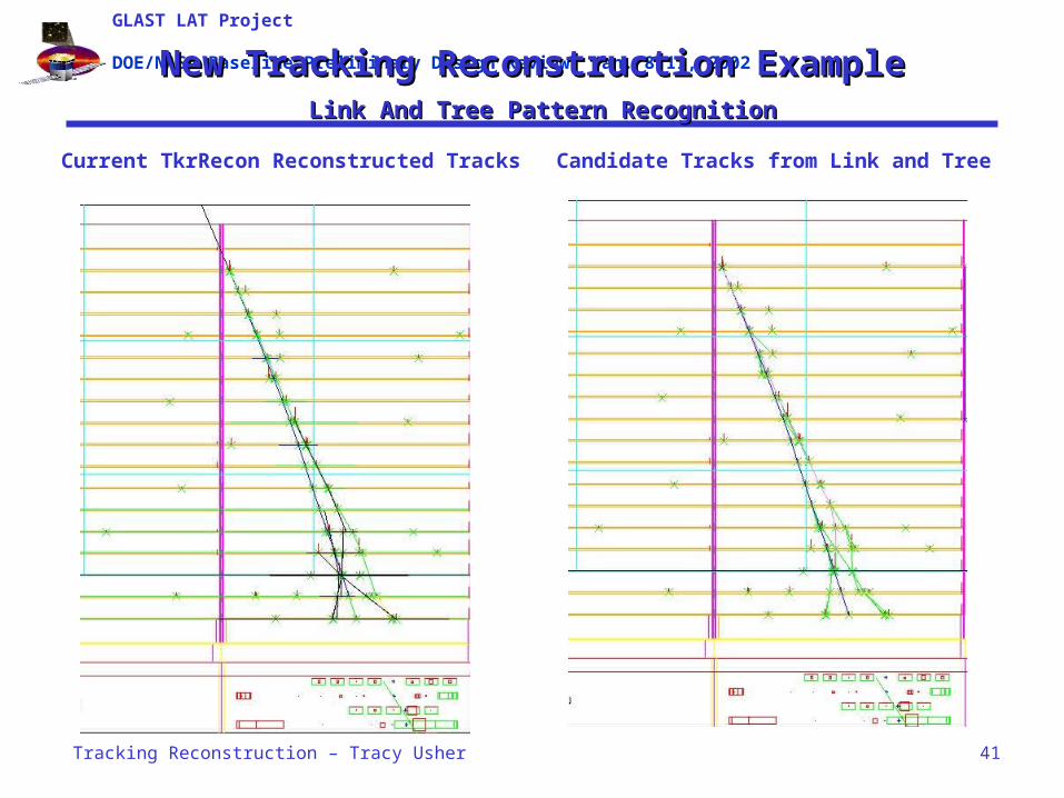
New Tracking Reconstruction ExampleNew Tracking Reconstruction Example Link And Tree Pattern RecognitionLink And Tree Pattern Recognition
Current TkrRecon Reconstructed Tracks
Candidate Tracks from Link and Tree

GLAST LAT Project
DOE/NASA Baseline-Preliminary Design Review, Jan. 8-11, 2002
Tracking Reconstruction – Tracy Usher 42
Tracker Reconstruction ManpowerTracker Reconstruction Manpower
Tracker Subsystem Manager– Robert Johnson (UCSC)
TKR Software Management– Tracy Usher (SLAC)– Leon Rochester (SLAC)
TKR software team at SLAC– Manpower
• Tracy Usher 1.0 FTE• Leon Rochester 1.0 FTE• Hiro Tajima 0.25 FTE
– Major Tasks• Track and Vertex Reconstruction• Geometry, calibration, etc.• Code Maintenance and
Documentation
TKR Software team at UCSC– Manpower
• Bill Atwood 0.75 FTE• Brian Baughman 0.50 FTE• Brandon Allgood 0.50 FTE
– Major Tasks• Track and Vertex Reconstruction UCSC group also heavily involved in
o Track Propagation o Background rejectiono Etc.
TKR Software team at Bari– Manpower
• N.Giglietto 0.8 FTE
• M.Brigida 1.0 FTE
• F. Loparco 0.5 FTE
• M.N. Mazziotta 0.1 FTE• F. Gargano 0.1
FTE
– Major Tasks• Simulation and Digitization• ToT
TKR Software team at Pisa– Manpower
• Michael Kuss 1.0 FTE• Johann Cohen-Tanugi 1.0 FTE
– Major Tasks• Vertex Finding and Fitting Effort in this area in startup
Total: 8.5 FTE’s spread over 4 institutions

GLAST LAT Project
DOE/NASA Baseline-Preliminary Design Review, Jan. 8-11, 2002
Tracking Reconstruction – Tracy Usher 43
Tracker Reconstruction ScheduleTracker Reconstruction Schedule
High priority, short term– Implement “initial plan” of new Tracker Reconstruction Due: 5/02– Convert to new output class formats Due: 5/02– Calibration software algorithms (hot/dead strips) Due: 5/02– Simulation and Digitization for GEANT4 Due: 10/02– On-going support for sim and recon
Moderate priority, intermediate term– Implement new Tracker Reconstruction Due: 10/02– Iterative Cal-Tkr reconstruction– Study Time over Threshold– Calibration database issues– Study alignment algorithms with Monte Carlo
Low priority, long term– On-going support for sim and recon– Implement alignment Due: early
2003

GLAST LAT Project
DOE/NASA Baseline-Preliminary Design Review, Jan. 8-11, 2002
Tracking Reconstruction – Tracy Usher 44
TkrBadStripsSvcTkrBadStripsSvc
TkrBadStripsSvc provides information to the reconstruction about the bad strips, through the abstract interface ITkrBadStripsSvc. At the moment, it makes no distinction between categories of “bad.” The most generally useful public methods are:
– getBadStrips(), which returns a list of bad strips,– isBadStrip(), which returns the status of a particular strip
In each case the arguments are either (tower, layer, axis) or index, the latter obtained from:
– getIndex(), which returns the index for a (tower,layer,axis) list.
TkrBadStripsSvc is currently used in the algorithm which groups adjacent hit strips into clusters.

GLAST LAT Project
DOE/NASA Baseline-Preliminary Design Review, Jan. 8-11, 2002
Tracking Reconstruction – Tracy Usher 45
SSD & Tray AlignmentSSD & Tray Alignment
Track based alignment– Minimize the 2 of the distance between SSD
hits and the track by adjusting SSD location and orientation
Parameters: x, y, z*, rotation around z– Rotations around x and y are optional– Overall z length is fixed to avoid under-
constraint• Overall z length will be fixed by LAT alignment
Matrix inversion– One large matrix inversion (SLD)
• 2496 x 2496 matrix
– Iterative procedure (Belle, DELPHI, ALEPH)• Align every SSD (tray) with respect to the rest of
SSDs (tray)• Iterate above procedure until adjustments
become sufficiently small
Z-scale ambiguity

GLAST LAT Project
DOE/NASA Baseline-Preliminary Design Review, Jan. 8-11, 2002
Tracking Reconstruction – Tracy Usher 46
Inter-Tower & LAT AlignmentInter-Tower & LAT Alignment
Inter-Tower alignment– Monitor tower movement by GRID deformation due to temperature
change• Temperature dependence
– Minimize the 2 of the distance between SSD hits and tracks from an adjacent tower by adjusting the tower location and orientation
LAT and Observatory alignment– Minimize the 2 of the distance between the nominal position of known
gamma-ray sources and the position measured by the LAT
– Define absolute z-scale of the LAT• Study the position of the known gamma-ray sources as a function of the incident
angle

GLAST LAT Project
DOE/NASA Baseline-Preliminary Design Review, Jan. 8-11, 2002
Tracking Reconstruction – Tracy Usher 47
Alignment EvaluationAlignment Evaluation
Comparison of results from two independent procedures– Large matrix inversion and iterative procedure
Comparison of tracking parameters from two different parts of the TKR
– Inter-tower, Upper-lower layers• Systematics can be studied by angular dependence
– Alternative layers• Overall tracking performance• Comparison with MC

GLAST LAT Project
DOE/NASA Baseline-Preliminary Design Review, Jan. 8-11, 2002
Tracking Reconstruction – Tracy Usher 48
Parameterization of Tracker ResponseParameterization of Tracker ResponseSimulating Strip Voltage and CurrentSimulating Strip Voltage and Current
The Basic Idea– After generation, electrons and holes will drift towards the n and p
electrodes respectively.– Due to the motion of carriers, induced current signals are generated on
the electrodes. The induced current signals are evaluated in 1 ns time steps using the general form of the Ramo’s theorem.
Implementation– adopt a parameterization derived from the HEED code:
• for each track nclus clusters are generated from a gaussian distribution with <nclus> = 4.16 clusters/µm and s = 0.11 clusters/µm
• the total number of e-h pairs is evaluated as npair=DE/3.6 eV
• to each cluster a charge q = e nclus/npair is assigned
• the average distance between clusters is defined as l=t/nclus
• the cluster are distributed along the track according to an exponential probability distribution with mean l
• These aspects are implemented in parameterization class

GLAST LAT Project
DOE/NASA Baseline-Preliminary Design Review, Jan. 8-11, 2002
Tracking Reconstruction – Tracy Usher 49
Parameterization of Tracker ResponseParameterization of Tracker ResponseAdding Dectector and Electronics NoiseAdding Dectector and Electronics Noise
Serial noise
•Metal strip resistance µ RMS
•MOSFET channel noise µ 1/gm
•Bulk resistance noise µ Rbulk
•Flicker noise
The noise is superimposed on the input current signal by adding spikes Poisson distributed in time (ENC=550 e).
The noise is due to both detector and front end electronics.
Parallel noise
•Polarization resistor noise µ 1/RP
•Leakage current noise µ iL

GLAST LAT Project
DOE/NASA Baseline-Preliminary Design Review, Jan. 8-11, 2002
Tracking Reconstruction – Tracy Usher 50
Parameterization of Tracker ResponseParameterization of Tracker ResponseSimulating Electronics ResponseSimulating Electronics Response
Front end electronics
detector preamplifier shaper
Rd Cd
Rf
Cf
gmgms
Rfs
Cfs
Cc
Id

GLAST LAT Project
DOE/NASA Baseline-Preliminary Design Review, Jan. 8-11, 2002
Tracking Reconstruction – Tracy Usher 51
Parameterization of Tracker ResponseParameterization of Tracker ResponseSimulating Time over ThresholdSimulating Time over Threshold
For each strip a threshold Vth,i is extracted from a gaussian distribution with <Vth>=160 mV and s=7 mV.
The Time over Threshold, or TOT, is defined as the time interval during which for at least one strip Vi>Vth,i.
Electronic parameters have to be confirmed by people working on electronics