glass sealed hermetic connectors - digikey electronics export/supplier...
TRANSCRIPT

J-2www.ittcannon.com
Dimensions shown in inches (mm)Specifications and dimensions subject to change
Hermetic Connectors
J
Her
met
ic C
on
nec
tors
Glass Sealed Hermetic Connectors
Users around the world have found that ITT Cannonhermetic connectors function reliably under extremeenvironmental conditions. Hermetic connectors areimpervious to most liquids and gases, including acids,alkalis, oils, gasoline, jet fuel and hydraulic fluids. Theycan take shock loads as high as 100 g’s with no loss inhermeticity, and can take extremes of both heat andcold with no loss of performance.
Manufacturing Expertise
Cannon compression glass seals are strong. A 50,000psi compression stress generates a sealing force thatcan withstand up to 10,000 psi differential pressure(pressure varies with connector type). Since it isindependent of adhesion, the seal has a temperaturecapability of -260° to +450° Fahrenheit. The seal hashigh radiation resistance and a leak rate of less than10-8 cc per second.
All ITT Cannon hermetic connectors are 100% testedafter fabrication. A stringent examination ensures thatall military specifications are met. The product is testedfor leak performance, dielectric withstanding voltageand insulation resistance.
200300
500
1,000
2,000
5,000
.25 .50 .75 1.00 1.25 1.50 1.75
10,000
20,000
.500 WEB THICKNESS
PRESSURE CAPABILITIES OF SOLID OR INDIVIDUALGLASS BEAD CONNECTORS
MA
XIM
UM
OPE
RATI
NG
PRE
SSU
RE (
psi)
.250 WEBTHICKNESS
.125 WEBTHICKNESS
DIAMETER OF GLASS BEAD
————————— Failure due to bending(35% of short time stress max)
—————— Failure due to shear(35% of short time stress max)
30,000
40,000
ca_J1-J50.qxd:Layout 1 2/10/11 8:51 AM Page 2

J-3www.ittcannon.com
Dimensions shown in inches (mm)Specifications and dimensions subject to change
Hermetic Connectors
J
Herm
etic Co
nn
ectors
Compression Glass Seals
Glass is an ideal electrical insulating material forconnectors. Its mechanical strength readily supportscontacts. The compression seal is achieved by placinga glass preform within the surrounding metal shell,heating the glass and shell to the glass meltingtemperature, and then cooling the assembly. As theassembly cools, the glass becomes rigid and the metalshell begins to compress the glass. This compressionprovides a very high strength, high reliability hermeticseal.
Custom Design Capabilities
Custom hermetic connectors can be manufactured tomeet special requirements. Hermetic connectors havebeen developed to withstand exposure to propellants,high pressure and high temperature conditions formissiles, “sub-safe” connectors for penetration feed-thru on ships and submarines, connectors for aircraftengines and many more.
This catalog provides a sample of the standardhermetic connectors available from Cannon. If youdon’t immediately find the connector that is right foryour application, we encourage you to call an ITTCannon technical sales representative in your area orcomplete and mail the business reply card at the backof this catalog.
Table of Contents
Miniature CircularKPTH / PVAH . . . . . . . . . . Page J-7 to J-12
Subminiature CircularKJLY / KJY / KJAY. . . . . . . . Page J-7 to J-12
Standard CircularGS . . . . . . . . . . . . . . . . . Page J-30 to J-38
Lightweight Sealed CircularKJAYAS. . . . . . . . . . . . . Page J- 28 to J-29
Thru-Bulkhead CircularBFH / TBFH . . . . . . . . . . Page J-39 to J-42
Microminiature DMDMH . . . . . . . . . . . . . Page J-43 to J-44
D Subminiature DD*H. . . . . . . . . . . . . . . . Page J-45 to J-48
ca_J1-J50.qxd:Layout 1 2/10/11 8:51 AM Page 3
J-4www.ittcannon.com
Dimensions shown in inches (mm)Specifications and dimensions subject to change
J
Her
met
ic C
on
nec
tors
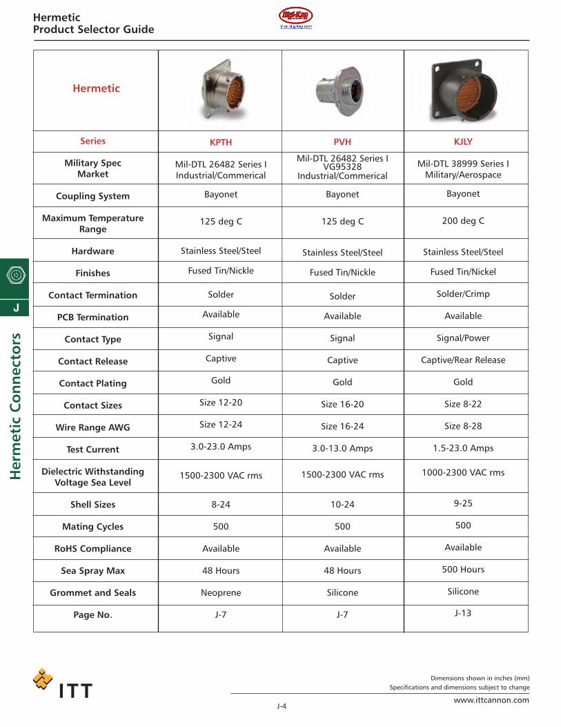
HermeticProduct Selector Guide
Series
Military SpecMarket
Coupling System
Maximum TemperatureRange
Hardware
Finishes
Contact Termination
PCB Termination
Contact Type
Contact Release
Contact Plating
Contact Sizes
Wire Range AWG
Test Current
Dielectric WithstandingVoltage Sea Level
Shell Sizes
Mating Cycles
RoHS Compliance
Sea Spray Max
Grommet and Seals
Page No.
KPTH
Mil-DTL 26482 Series IIndustrial/Commerical
Bayonet
125 deg C
Stainless Steel/Steel
Fused Tin/Nickle
Solder
Available
Signal
Captive
Gold
Size 12-20
Size 12-24
3.0-23.0 Amps
1500-2300 VAC rms
8-24
500
Available
48 Hours
Neoprene
J-7
PVH
Mil-DTL 26482 Series IVG95328
Industrial/Commerical
Bayonet
125 deg C
Stainless Steel/Steel
Fused Tin/Nickle
Solder
Available
Signal
Captive
Gold
Size 16-20
Size 16-24
3.0-13.0 Amps
1500-2300 VAC rms
10-24
500
Available
48 Hours
Silicone
J-7
Hermetic
KJLY
Mil-DTL 38999 Series IMilitary/Aerospace
Bayonet
200 deg C
Stainless Steel/Steel
Fused Tin/Nickel
Solder/Crimp
Available
Signal/Power
Captive/Rear Release
Gold
Size 8-22
Size 8-28
1.5-23.0 Amps
1000-2300 VAC rms
9-25
500
Available
500 Hours
Silicone
J-13
ca_J1-J50.qxd:Layout 1 2/10/11 8:51 AM Page 4

J-5www.ittcannon.com
Dimensions shown in inches (mm)Specifications and dimensions subject to change
J
Herm
etic Co
nn
ectors
HermeticProduct Selector Guide
Series
Military SpecMarket
Coupling System
Maximum TemperatureRange
Hardware
Finishes
Contact Termination
PCB Termination
Contact Type
Contact Release
Contact Plating
Contact Sizes
Wire Range AWG
Test Current
Dielectric WithstandingVoltage Sea Level
Shell Sizes
Mating Cycles
RoHS Compliance
Sea Spray Max
Grommet and Seals
Page No.
KJY
Mil-DTL 38999 Series IIMilitary/Aerospace
Bayonet
200 deg C
Stainless Steel/Steel
Cadmium/Nickel
Solder/Crimp
Available
Signal/Power
Captive/Rear Releaseavailable
Gold
Size 8-22
Size 8-28
1.5-23.0 Amps
1000-2300 VAC rms
8-24
250 with spring fingers
Available
500 Hours
Silicone
J-13
KJAY
Mil-DTL 38999 Series IIIMilitary/Aerospace
Triple Start
200 deg C
Stainless Steel/Steel
Nickel
Solder/Crimp
Available
Signal/Power
Captive/Rear Releaseavailable
Gold
Size 8-22
Size 8-28
1.5-23.0 Amps
1000-2300 VAC rms
9-25
500
Available
500 Hours
Silicone
J-13
Hermetic
KJAYA
Mil-DTL 38999 Series IIIMilitary/Aerospace
Triple Start
125 deg C
Aluminum and Stainless Steel
Cadmium/Nickel
Solder/Crimp
Available
Signal/Power
Captive/Rear Release
Gold
Size 8-22
Size 8-28
1.5-23.0 Amps
1000-2300 VAC rms
9-25
500
Available
500 Hours
Silicone
J-28
ca_J1-J50.qxd:Layout 1 2/10/11 8:51 AM Page 5

J-6www.ittcannon.com
Dimensions shown in inches (mm)Specifications and dimensions subject to change
J
Her
met
ic C
on
nec
tors
HermeticProduct Selector Guide
Series
Military SpecMarket
Coupling System
Maximum TemperatureRange
Hardware
Finishes
Contact Termination
PCB Termination
Contact Type
Contact Release
Contact Plating
Contact Sizes
Wire Range AWG
Test Current
Dielectric WithstandingVoltage Sea Level
Shell Sizes
Mating Cycles
RoHS Compliance
Sea Spray Max
Grommet and Seals
Page No.
GS / BFH / TBFH
Mil-L-5015 TypeMilitary / Aerospace
Threaded
150 deg C
Stainless Steel/Steel
Fused Tin/Nickle
Solder/Crimp
Available
Signal/Power
Captive/Rear Release
Tin/Gold
Size 0-16
Size 8-24
10-100 Amps
1500-2300 VAC rms
8-40
250
Available
48 Hours
Silicone
J-30
Hermetic
D*H
Mil-DTL 24308 Military/Aerospace
Jack Screw
150 deg C
Stainless Steel/Steel
Fused Tin/Nickel
Solder
Available
Signal/Power
Captive
Gold
Size 8-22
Size 8-28
1.5-23.0 Amps
300 VAC rms
A, E, B, C, D
250
Available
48 Hours
Silicone
J-45
MDMH
Mil-DTL-83513 TypeMilitary / Aerospace
Jack Screw
150 deg C
Stainless Steel/Steel
Fused Tin/Nickle
Solder
Available
Signal
Captive
Gold
Size 24
Size 26-30
3.0 Amps Max
150 VAC rms
9, 15, 21, 25, 31, 37, 51
250
Available
48 Hours
Silicone
J-43
ca_J1-J50.qxd:Layout 1 2/10/11 8:51 AM Page 6

MIL-C-26482 Miniature CircularKPTH/PVAH
• Pin contacts in a compression glass seal• Solder pot or eyelet termination• Leak rate not in excess of .01 micron cu. ft./hr.• 100 psi differential causes no detectable leak-
age in excess of .01 micron cu. ft./hr.• 100 g shock with no loss of hermeticity.• Thermetic shock from -75°C to +200°C without
affecting leakage rate.
ITT Cannon hermetically-sealed KPT and PVA (MIL-C-26842, Series I and II) connectors are designed for those applications and environmentsthat require delicate mechanisms to be protectedfrom variations in atmospheric pressure.
These miniature, circular connectors have broad-base commercial, military and industrial applica-tions, ranging from general purpose to space andlunar environments.
The receptacles are available with pin contactsonly and in three shell styles: box mountingKPT02H, solder mounting KPT01H, and jam nutKPT07H for Series I; box mounting PVA0, soldermounting PVA3, and jam nut PVA7 for Series II.Contact arrangements are tooled in a full leak-free compression glass web.
KPT I H 18 A 32 P NMS 3113 H 18 C 32 P N
SERIES PREFIXSHELL STYLECLASSSHELL SIZEMATERIAL AND CONTACT TERMINATIONCONTACT ARRANGEMENTCONTACT TYPEALTERNATE INSERT POSITIONMODIFICATION CODE
KPTH - Series I
SERIES PREFIXKPT — ITT Cannon PrefixMS — Complies with MIL-C-26482
Series I with interfacial seal(when specified as shown).
SHELL STYLEITT Cannon designation01 — Solder Mounting Receptacle02 — Box Mounting Receptacle
(not available in MS)07 — Jam Nut Mounting Receptacle
MS designation3113 — Solder Mounting Receptacle3114 — Jam Nut Receptacle
CLASSH — Hermetic
SHELL SIZE8, 10, 12, 14, 16, 18, 20, 22, 24
MATERIAL AND CONTACT TERMINATIONC — Steel Shell and Solder Pot Contacts
(MS specification)Y — Steel Shell and Eyelet Contacts (MS
specification)A — Stainless Shell & Solder Pot Contacts
(not MS approved)B — Stainless Shell & Eyelet Contacts (not
MS approved)No designator — Connector without face seal and
with solder pot contacts andsteel shell (not MS approved).
CONTACT ARRANGEMENTSSee page J-8.
CONTACT TYPEP — PinS — Socket (Consult factory)
ALTERNATE INSERT POLARIZATIONN (normal), W, X, Y, and Z (N designator not applicable to MS)
MODIFICATION CODEConsult factory (not applicable to MS).
How To Order
PVA 7 H 18 B 32 P NMS 3449 H 18 C 32 P N
SERIES PREFIXSHELL STYLECLASSSHELL SIZEMATERIAL AND CONTACT TERMINATIONCONTACT ARRANGEMENTCONTACT TYPEALTERNATE INSERT POLARIZATION
PVA - Series II
SERIES PREFIXPVA — ITT Cannon Equivalent
MIL-C-26482 (Series II)PV — ITT Cannon Prefix, Stainless
Steel HardwareMS — Not currently available
SHELL STYLEITT Cannon Numbers:0 — Box Mounting Receptacle3 — Solder Mounting Receptacle7 — Jam Nut Mounting
MS designation3440 — PVA0H3443 — PVA3H3449 — PVA7H
CLASSH — Hermetic
SHELL SIZE8, 10, 12, 14, 16, 18, 20, 22, 24
MATERIAL AND CONTACT TERMINATIONB — PV only — Solder Pot ContactsC — MS only — Solder Pot Contacts
CONTACT ARRANGEMENTSSee page J-8.
CONTACT TYPEP — PinS — Socket (Consult factory)
ALTERNATE INSERT POLARIZATIONN (normal), W, X, Y, and Z
MODIFICATION CODEConsult factory
J-7www.ittcannon.com
Dimensions shown in inches (mm)Specifications and dimensions subject to change
J
Herm
etic Co
nn
ectors
ca_J1-J50.qxd:Layout 1 2/10/11 8:51 AM Page 7

J-8www.ittcannon.com
Dimensions shown in inches (mm)Specifications and dimensions subject to change
J
Her
met
ic C
on
nec
tors
Cannon KJL Miniature ConnectorKPTH/PVAH
ELECTRICAL
Number of contacts 2 thru 61
Wire Size,AWG #16, #20
ContactTermination Solder (PC Tails-Consult Factory)
ContactRating RATED TEST MV
SIZE AMPS CURRENT DROP20 7.5 5.0 7016 22.0 13.0 75
ServiceRating TEST AC
VOLT SERVICE (rms) DCSea 1 1500 2100
Level 2 2300 3200
(Face view of pin insert)
The diagram above indicates alternate insert positions.The five positions (W, X, Y, Z and Normal) differ in de-gree of rotation for various sizes and arrangements.For the exact degree of rotation, and for the list of con-tact arrangements and alternate positions available,refer to the tabulation at right.
No. of Shell Arr. Degrees of RotationContacts Size No. W X Y Z
2 8 8-2 58 122 — —8 8-3 60 210 — —
38 8-33 90 — — —
4 8 8-4 45 — — —10 10-6 90 — — —
610 10-98 90 180 240 270
3 12 12-3 — — 180 —8 12 12-8 90 112 203 292
10 12 12-10 60 155 270 2955 14 14-5 40 92 184 273
12 14 14-12 43 90 — —15 14 14-15 17 110 155 234
No. of Shell Arr. Degrees of RotationContacts Size No. W X Y Z
18 14 14-18 15 90 180 27019 14 14-19 30 165 315 —
8 16 16-8 54 152 180 33126 16 16-26 60 — 275 33811 18 18-11 62 119 241 34032 18 18-32 85 138 222 26516 20 20-16 238 318 333 34741 20 20-41 45 126 225 —21 22 22-21 16 135 175 34941 22 22-41 39 135 264 19655 22 22-55 30 142 226 31461 24 24-61 90 180 270 324
Standard Data
Contact Arrangements
Alternate Insert Positions
MATERIALS AND FINISHES
ShellInsulatorJam NutBayonet PinsSeals
O Ring (Flange)Contacts
KPT (Series I)Steel, electrodeposited tin over cadmiumCompression glassSteel
Silicone and polychloroprene
NitrileSteel, electrodeposited tin over cadmium
PVA (Series II)Steel, .0001 min. tin over nickelCompression glassSteel, nickel platedStainless steelStatic and interfacial-fluorosilicone/silicone elastomerSilicone elastomerFerrous alloy, plated .00005 min. goldover nickel
MECHANICAL
Shell Styles
Shell SizesPolarization/CouplingService Class
KPT (Series I)1 — Solder mounting receptacle2 — Box mounting receptacle7 — Jam nut mounting receptacle8 thru 245 Keyway/3 point bayonetH — Hermetic
PVA (Series II)0 — Box mounting receptacle3 — Solder mounting receptacle7 — Jam nut receptacle8 thru 245 Keyway/3 point bayonetH — Hermetic
Drawing not to scale;face view of pin insert shown
Shell Size 8-2 8-3 8-4 8-33 10-6 10-98 12-3 12-8 12-10 14-5No. of Contacts 2-#20 3-#20 4-#20 3-#20 6-#20 6-#20 3-#16 8-#20 10-#20 5-#16Service Rating 1 1 1 1 1 1 2 1 1 2
Shell Size 14-12 14-15 14-18 14-19 16-8 16-26 18-11 18-32No. of Contacts 8-#20 4-#20 14-#16 1-#16 18-#20 19-#20 8-#16 26-#20 11-#16 32-#20Service Rating 1 1 1 1 2 1 2 1
Shell Size 20-16 20-41 22-21 22-41 22-55 24-61No. of Contacts 16-#16 41-#20 21-#16 27-#20 14-#16 55-#20 61-#20Service Rating 2 1 2 2 1 1
ca_J1-J50.qxd:Layout 1 2/10/11 8:51 AM Page 8

J-9www.ittcannon.com
Dimensions shown in inches (mm)Specifications and dimensions subject to change
J
Herm
etic Co
nn
ectors
MIL-C-26482 Miniature CircularKPTH/PVAH
Box Mounting Receptacles
KPT02H
ShellSize
81012141518202224
A+ .001 (0.03)
- .005 (0.13)
.473 (12.01)
.590 (14.99)
.750 (19.05)
.875 (22.22)1.000 (25.40)1.125 (28.58)1.250 (31.75)1.375 (34.92)1.500 (38.10)
B± .020 (0.51)
1.062 (26.97)1.250 (31.57)1.375 (34.82)1.500 (38.10)1.625 (41.28)1.750 (44.45)1.875 (47.62)2.050 (52.07)2.250 (57.15)
F
.344 (8.74)
.344 (8.74)
.344 (8.74)
.344 (8.74)
.344 (8.74)
.344 (8.74)
.344 (8.74)
.344 (8.74)
.320 (8.13)
K± .020 (0.51)
.438 (11.13)
.438 (11.13)
.438 (11.13)
.438 (11.13)
.438 (11.13)
.438 (11.13)
.468 (11.89)
.468 (11.89)
.500 (12.70)
L± .005 (0.13)
.546 (13.87)
.546 (13.87)
.546 (13.87)
.546 (13.87)
.546 (13.87)
.546 (13.87)
.608 (15.44)
.640 (16.26)
.673 (17.09)
N + .001 (0.03)- .005 (0.13)
.562 (14.27)
.672 (17.07)
.781 (19.84)
.906 (23.01)1.031 (26.19)1.156 (29.36)1.250 (31.75)1.375 (34.92)1.500 (38.10)
R± .005 (0.13)
.594 (15.09)
.719 (18.26)
.812 (20.62)
.906 (22.99)
.969 (24.62)1.062 (26.97)1.156 (29.36)1.250 (31.75)1.375 (34.92)
S± .010 (0.25)
.812 (20.62)
.938 (23.83)1.031 (26.19)1.125 (28.58)1.219 (30.96)1.312 (33.32)1.438 (36.53)1.562 (39.67)1.687 (42.85)
T± .005 (0.13)
.120 (3.05)
.120 (3.05)
.120 (3.05)
.120 (3.05)
.120 (3.05)
.120 (3.05)
.120 (3.05)
.120 (3.05)
.147 (3.73)
V± .010 (0.25)
.062 (1.57)
.062 (1.57)062 (1.57)062 (1.57)062 (1.57)062 (1.57).094 (2.39).094 (2.39).094 (2.39)
ShellSize
81012141518202224
A+ .001 (0.03)
- .005 (0.13)
.473 (12.01)
.590 (14.99)
.750 (19.05)
.875 (22.22)1.000 (25.40)1.125 (28.58)1.250 (31.75)1.375 (34.92)1.500 (38.10)
F
.370 (9.40)
.370 (9.40)
.370 (9.40)
.370 (9.40)
.370 (9.40)
.370 (9.40)
.370 (9.40)
.370 (9.40)
.340 (8.64)
L± .005 (0.13)
.546 (13.87)
.546 (13.87)
.546 (13.87)
.546 (13.87)
.546 (13.87)
.546 (13.87)
.608 (15.44)
.640 (16.26)
.673 (17.09)
N + .001 (0.03)- .005 (0.13)
.562 (14.27)
.672 (17.07)
.781 (19.84)
.906 (23.01)1.031 (26.19)1.156 (29.36)1.250 (31.75)1.375 (34.92)1.500 (38.10)
P± .005 (0.13)
.031 (0.79)
.031 (0.79)
.031 (0.79)
.031 (0.79)
.031 (0.79)
.031 (0.79)
.031 (0.79)
.031 (0.79)
.031 (0.79)
S + .010 (0.25)- .016 (0.41)
.631 (16.03)
.756 (19.20)
.850 (21.59)
.975 (24.76)1.100 (27.94)1.224 (31.09)1.318 (33.48)1.444 (36.68)1.569 (39.85)
V± .005 (0.13)
.421 (10.69)
.421 (10.69)
.421 (10.69)
.421 (10.69)
.421 (10.69)
.421 (10.69)
.485 (12.32)
.485 (12.32)
.518 (13.16 )
Solder Mounting Receptacles
MS 3113H KPT01H
ca_J1-J50.qxd:Layout 1 2/10/11 8:51 AM Page 9

J-10www.ittcannon.com
Dimensions shown in inches (mm)Specifications and dimensions subject to change
J
Her
met
ic C
on
nec
tors
Cannon KJL Miniature ConnectorKPTH/PVAH
Jam Nut Receptacle
MS 3114H
ShellSize
81012141518202224
A- .003 (0.08)
.471 (11.96)
.588 (14.94)
.748 (19.00)
.873 (22.17)
.998 (25.35)1.123 (28.52)1.248 (31.70)1.373 (34.87)1.498 (38.05)
E± .005 (0.13)
.525 (13.34)
.650 (16.51)
.813 (20.65)
.937 (23.80)1.061 (26.95)1.186 (30.12)1.311 (33.30)1.436 (36.47)1.561 (39.65)
GMax.
1.078 (27.38)1.203 (30.56)1.391 (35.33)1.516 (38.51)1.641 (41.68)1.766 (44.86)1.954 (49.63)2.078 (52.78)2.203 (55.96)
K + .001 (0.03)- .016 (0.41)
.094 (2.39)
.094 (2.39)
.094 (2.39)
.094 (2.39)
.094 (2.39)
.094 (2.39)
.125 (3.18)
.125 (3.18)
.125 (3.18)
M± .015 (0.38)
.707 (17.96)
.707 (17.96)
.707 (17.96)
.707 (17.96)
.707 (17.96)
.707 (17.96)
.895 (22.73)
.895 (22.73)
.895 (22.73)
Min.
.062 (1.57)
.062 (1.57)
.062 (1.57)
.062 (1.57)
.062 (1.57)
.062 (1.57)
.062 (1.57)
.062 (1.57)
.062 (1.57)
Max.
.125 (3.18)
.125 (3.18)
.125 (3.18)
.125 (3.18)
.125 (3.18)
.125 (3.18)
.250 (6.35)
.250 (6.35)
.250 (6.35)
SMax.
.954 (24.23)1.078 (27.38)1.266 (32.16)1.391 (35.33)1.516 (38.51)1.641 (41.68)1.828 (46.43)1.954 (49.63)2.078 (52.78)
V
9/16-24UNEF-2A11/16-24UNEF-2A
7/8-20UNEF-2A1-20UNEF-2A
1-1/8-18UNEF-2A1-1/4-18UNEF-2A1-3/8-18UNEF-2A1-1/2-18UNEF-2A1-5/8-18UNEF-2A
ShellSize
�81012141518202224
A
.565 (14.35)
.675 (17.14)
.784 (19.91)
.909 (23.09)1.034 (26.26)1.159 (29.44)1.253 (31.83)1.378 (35.00)1.503 (38.18)
R*
.594 (15.09)
.719 (18.26)
.812 (20.62)
.906 (23.01)
.969 (24.62)1.062 (26.97)1.156 (29.36)1.250 (31.75)1.375 (34.92)
± .005 (0.13)
.125 (3.18)
.125 (3.18)
.125 (3.18)
.125 (3.18)
.125 (3.18)
.125 (3.18)
.125 (3.18)
.125 (3.18)
.155 (3.94)
Screw
#4#4#4#4#4#4#4#4#6
Panel Cutouts - KPTH
Flange Mounted Receptacle(Front Mounting)
KPT07H
Jam Nut Receptacle
P
KPT02H / KPT01H KPT02H ShellSize
81012141518202224
A
.567 (14.35)
.692 (17.14)
.880 (19.91)1.005 (23.09)1.130 (26.26)1.255 (29.44)1.380 (31.83)1.505 (35.00)1.630 (38.18)
B
.531 (13.49)
.656 (16.66)
.819 (20.80)
.943 (23.95)1.067 (27.10)1.192 (30.28)1.317 (33.45)1.442 (36.63)1.567 (39.80)
KPT07H
*Not used in KPT01H connectors.
ca_J1-J50.qxd:Layout 1 2/10/11 8:51 AM Page 10

J-11www.ittcannon.com
Dimensions shown in inches (mm)Specifications and dimensions subject to change
J
Herm
etic Co
nn
ectors
MIL-C-26482 Miniature CircularKPTH/PVAH
Box Mounting Receptacles
PV0H / PVA0H
ShellSize
81012141518202224
A+ .001 (0.03)- .005 (0.13)
.473 (12.01)
.590 (14.99)
.750 (19.05)
.875 (22.22)1.000 (25.40)1.125 (28.58)1.250 (31.75)1.375 (34.92)1.500 (38.10)
B± .020 (0.51)
1.062 (26.97)1.250 (31.57)1.375 (34.82)1.500 (38.10)1.625 (41.28)1.750 (44.45)1.875 (47.62)2.050 (52.07)2.250 (57.15)
F± .010 (0.25)
.588 (14.94)
.588 (14.94)
.588 (14.94)
.588 (14.94)
.588 (14.94)
.588 (14.94)
.650 (16.51)
.650 (16.51)
.650 (16.51)
J± .010 (0.25)
.115 (2.92)
.115 (2.92)
.115 (2.92)
.115 (2.92)
.115 (2.92)
.115 (2.92)
.083 (2.11)
.115 (2.92)
.115 (2.92)
G± .016 (0.41)
.062 (1.57)
.062 (1.57)
.062 (1.57)
.062 (1.57)
.062 (1.57)
.062 (1.57)
.094 (2.39)
.094 (2.39)
.094 (2.39)
LMax. Ref.
.801 (20.35)
.801 (20.35)
.801 (20.35)
.801 (20.35)
.801 (20.35)
.801 (20.35)
.863 (21.92)
.895 (22.73)
.895 (22.73)
N + .001 (0.03)- .005 (0.13)
.562 (14.27)
.672 (17.07)
.781 (19.84)
.906 (23.01)1.031 (26.19)1.156 (29.36)1.250 (31.75)1.375 (34.92)1.500 (38.10)
R± .005 (0.13)
.594 (15.09)
.719 (18.26)
.812 (20.62)
.906 (22.99)
.969 (24.62)1.062 (26.97)1.156 (29.36)1.250 (31.75)1.375 (34.92)
S± .010 (0.25)
.812 (20.62)
.938 (23.83)1.031 (26.19)1.125 (28.58)1.219 (30.96)1.312 (33.32)1.438 (36.53)1.562 (39.67)1.687 (42.85)
T± .005 (0.13)
.120 (3.05)
.120 (3.05)
.120 (3.05)
.120 (3.05)
.120 (3.05)
.120 (3.05)
.120 (3.05)
.120 (3.05)
.147 (3.73)
U± .030 (0.76)
.148 (3.76)
.148 (3.76)
.148 (3.76)
.148 (3.76)
.148 (3.76)
.148 (3.76)
.148 (3.76)
.148 (3.76)
.148 (3.76)
V± .030 (0.76)
.218 (5.54)
.218 (5.54)
.218 (5.54)
.218 (5.54)
.218 (5.54)
.218 (5.54)
.218 (5.54)
.186 (4.72)
.186 (4.72)
ShellSize
81012141518202224
A+ .001 (0.03)
- .005 (0.13)
.473 (12.01)
.590 (14.99)
.750 (19.05)
.875 (22.22)1.000 (25.40)1.125 (28.58)1.250 (31.75)1.375 (34.92)1.500 (38.10)
F
.588 (14.94)
.588 (14.94)
.588 (14.94)
.588 (14.94)
.588 (14.94)
.588 (14.94)
.650 (16.51)
.650 (16.51)
.650 (16.51)
J± .005 (0.13)
.136 (3.45)
.136 (3.45)
.136 (3.45)
.136 (3.45)
.136 (3.45)
.136 (3.45)
.136 (3.45)
.168 (4.27)
.168 (4.27)
L- .005 (0.13)
.801 (20.35)
.801 (20.35)
.801 (20.35)
.801 (20.35)
.801 (20.35)
.801 (20.35)
.863 (21.92)
.895 (22.73)
.895 (22.73)
N+ .001 (0.03)- .005 (0.13)
.562 (14.27)
.672 (17.07)
.781 (19.84)
.906 (23.01)1.031 (26.19)1.156 (29.36)1.250 (31.75)1.375 (34.92)1.500 (38.10)
S± .010 (0.25)
.625 (15.88)
.750 (19.05)
.844 (21.44)
.969 (24.62)1.094 (27.79)1.218 (30.94)1.312 (33.32)1.438 (36.53)1.564 (39.73)
U± .005 (0.13)
.148 (3.76)
.148 (3.76)
.148 (3.76)
.148 (3.76)
.148 (3.76)
.148 (3.76)
.148 (3.76)
.116 (2.95)
.116 (2.95)
V± .005 (0.13)
.218 (5.54)
.218 (5.54)
.218 (5.54)
.218 (5.54)
.218 (5.54)
.218 (5.54)
.218 (5.54)
.186 (4.76)
.186 (4.76)
Solder Mounting Receptacle
PV3H / PVA3H
Contact Ext.
ca_J1-J50.qxd:Layout 1 2/10/11 8:51 AM Page 11

J-12www.ittcannon.com
Dimensions shown in inches (mm)Specifications and dimensions subject to change
J
Her
met
ic C
on
nec
tors
MIL-C-26482 Miniature CircularKPTH/PVAH
Jam Nut Receptacle
PV7H / PVA7H
A+ .001 (0.03)- .005 (0.13)
.473 (12.01)
.590 (14.99)
.750 (19.05)
.875 (22.22)1.000 (25.40)1.125 (28.58)1.250 (31.75)1.375 (34.92)1.500 (38.10)
B+ .016 (0.41)- .015 (0.38)
1.062 (26.97)1.187 (31.75)1.375 (34.92)1.500 (38.10)1.625 (41.28)1.750 (44.45)1.938 (47.62)2.062 (52.07)2.187 (57.15)
E± .005 (0.13)
.525 (13.34)
.650 (16.51)
.813 (20.65)
.937 (23.80)1.061 (26.95)1.186 (30.12)1.311 (33.30)1.436 (36.47)1.561 (39.65)
J± .010 (0.25)
.368 (9.35)
.368 (9.35)
.368 (9.35)
.368 (9.35)
.368 (9.35)
.368 (9.35)
.368 (9.35)
.368 (9.35).395 (10.03)
K± .008 (0.20)
.105 (2.67)
.105 (2.67)
.105 (2.67)
.105 (2.67)
.105 (2.67)
.105 (2.67)
.138 (3.51)
.138 (3.51)
.138 (3.51)
LMax. Ref.
.820 (20.83)
.820 (20.83)
.820 (20.83)
.820 (20.83)
.820 (20.83)
.820 (20.83)
.920 (23.37)
.920 (23.37)
.951 (24.16)
M± .008 (0.20)
.699 (17.75)
.699 (17.75)
.699 (17.75)
.699 (17.75)
.699 (17.75)
.699 (17.75)
.763 (19.38)
.763 (19.38)
.793 (20.14)
PMin / Max
.062/.187 (1.57/4.75)
.062/.187 (1.57/4.75)
.062/.187 (1.57/4.75)
.062/.187 (1.57/4.75)
.062/.187 (1.57/4.75)
.062/.187 (1.57/4.75)
.062/.187 (1.57/4.75)
.062/.187 (1.57/4.75)
.062/.187 (1.57/4.75)
ShellSize
81012141518202224
S+ .016 (0.41)- .015 (0.38)
.938 (23.83)1.062 (14.99)1.250 (19.05)1.375 (34.92)1.500 (38.10)1.625 (41.28)1.812 (46.02)1.938 (49.23)2.062 (52.37)
TUNEF-2A
.5625-24
.6875-24.875 -20
1.000 -201.125 -181.250 -181.375 -181.500 -181.625 -18
U± .030 (0.76)
.104 (2.64)
.104 (2.64)
.104 (2.64)
.104 (2.64)
.104 (2.64)
.104 (2.64)
.069 (1.75)
.069 (1.75)
.039 (0.99)
V± .030 (0.76)
.174 (4.42)
.174 (4.42)
.174 (4.42)
.174 (4.42)
.174 (4.42)
.174 (4.42)
.139 (3.53)
.139 (3.53)
.109 (2.77)
Contact Ext.
ca_J1-J50.qxd:Layout 1 2/10/11 8:51 AM Page 12
J-13www.ittcannon.com
Dimensions shown in inches (mm)Specifications and dimensions subject to change
J
Herm
etic Co
nn
ectors
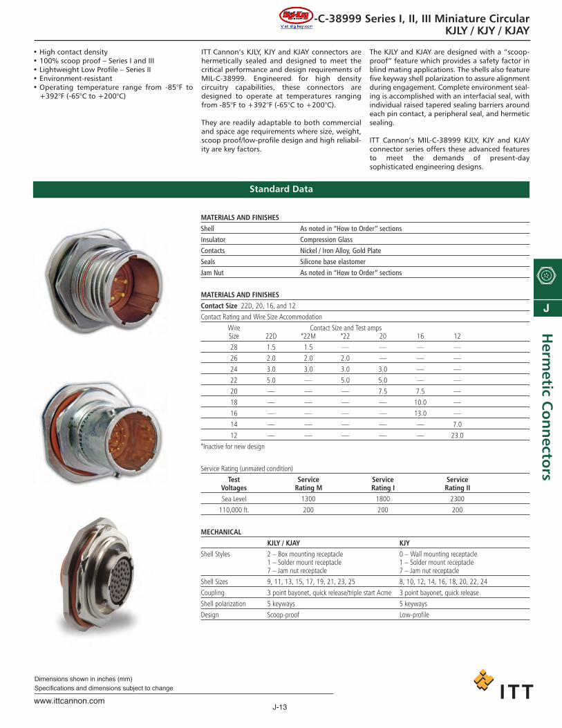
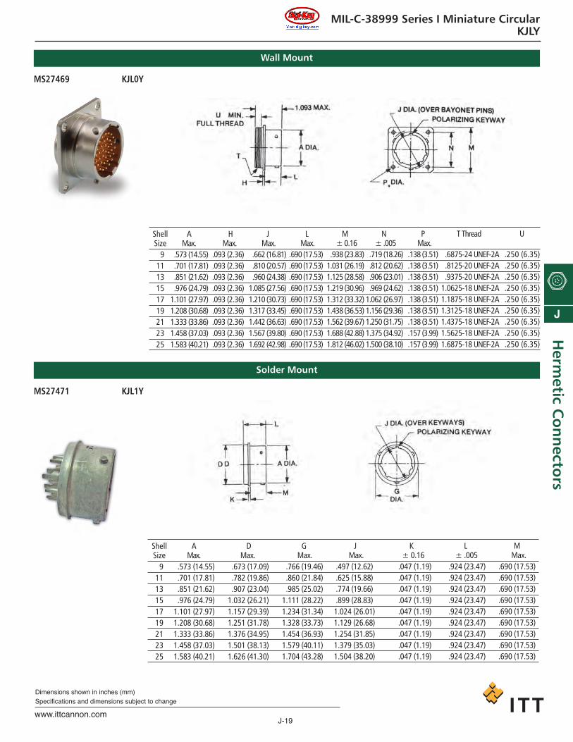
MIL-C-38999 Series I, II, III Miniature CircularKJLY / KJY / KJAY
• High contact density• 100% scoop proof – Series I and III• Lightweight Low Profile – Series II• Environment-resistant• Operating temperature range from -85°F to
+392°F (-65°C to +200°C)
ITT Cannon’s KJLY, KJY and KJAY connectors arehermetically sealed and designed to meet thecritical performance and design requirements of MIL-C-38999. Engineered for high density circuitry capabilities, these connectors are designed to operate at temperatures rangingfrom -85°F to +392°F (-65°C to +200°C).
They are readily adaptable to both commercialand space age requirements where size, weight,scoop proof/low-profile design and high reliabil-ity are key factors.
The KJLY and KJAY are designed with a “scoop-proof” feature which provides a safety factor inblind mating applications. The shells also featurefive keyway shell polarization to assure alignmentduring engagement. Complete environment seal-ing is accomplished with an interfacial seal, withindividual raised tapered sealing barriers aroundeach pin contact, a peripheral seal, and hermeticsealing.
ITT Cannon’s MIL-C-38999 KJLY, KJY and KJAYconnector series offers these advanced featuresto meet the demands of present-daysophisticated engineering designs.
Standard Data
MATERIALS AND FINISHESShell As noted in “How to Order” sectionsInsulator Compression GlassContacts Nickel / Iron Alloy, Gold PlateSeals Silicone base elastomerJam Nut As noted in “How to Order” sections
MATERIALS AND FINISHESContact Size 22D, 20, 16, and 12
Contact Rating and Wire Size Accommodation
Wire Contact Size and Test ampsSize 22D *22M *22 20 16 12
28 1.5 1.5 — — — —
26 2.0 2.0 2.0 — — —
24 3.0 3.0 3.0 3.0 — —
22 5.0 — 5.0 5.0 — —
20 — — — 7.5 7.5 —
18 — — — — 10.0 —
16 — — — — 13.0 —
14 — — — — — 7.0
12 — — — — — 23.0
*Inactive for new design
Service Rating (unmated condition)
Test Service Service ServiceVoltages Rating M Rating I Rating IISea Level 1300 1800 2300
110,000 ft. 200 200 200
MECHANICALKJLY / KJAY KJY
Shell Styles 2 – Box mounting receptacle 0 – Wall mounting receptacle1 – Solder mount receptacle 1 – Solder mount receptacle7 – Jam nut receptacle 7 – Jam nut receptacle
Shell Sizes 9, 11, 13, 15, 17, 19, 21, 23, 25 8, 10, 12, 14, 16, 18, 20, 22, 24
Coupling 3 point bayonet, quick release/triple start Acme 3 point bayonet, quick release
Shell polarization 5 keyways 5 keyways
Design Scoop-proof Low-profile
ca_J1-J50.qxd:Layout 1 2/10/11 8:51 AM Page 13

J-14www.ittcannon.com
Dimensions shown in inches (mm)Specifications and dimensions subject to change
J
Her
met
ic C
on
nec
tors
MIL-C-38999 Series I, II, III Miniature CircularKJLY / KJY / KJAY
Test Data
TEST PARAGRAPHDESCRIPTION REFERENCE REQUIREMENTSThermal Shock 4.7.3 Unmated receptacles shall be subjected to 10 cycles of thermal shock per Step 1 and Step 2 of MIL-C-38999.
Air Leakage 4.7.5 The connector shall be mounted in a suitable test apparatus. A pressure differential of 1 atmosphere shall be applied across the connector. A suit-able means to determine the leakage through the connector of air or other pressurizing gas, containing not less than 10 percent helium by volume,shall be employed while the specified pressure is applied. There shall be no evidence of leakage in excess of 0.01 micron ft3/h ( x 10-7 cm3/s).
Coupling Torque 4.7.6 For qualification testing, mating halves shall be coupled and uncoupled; the forces or torques which must be applied to facilitate full coupling anduncoupling shall be measured and recorded. For quality conformance, suitable gages may be used instead of the appropriate counterparts. The cou-pling torque for mating and unmating of counterpart connectors shall meet the requirements of Table III, paragraph 4.7.6 MIL-C-38999.
Insulation Resistance 4.7.9.2 Insulation Resistance at ambient temperature — Unmated connectors shall be tested as specified in method 3003 of MIL-STD-1344. Connectorsshall be mated when testing after altitude immersion and humidity. The insulation resistance between any pair of contacts and between any con-tact and the shell shall be greater than 5,000 megohms. Insulation resistance after altitude immersion shall be 10,000 megohms minimum. Insula-tion resistance after humidity shall be 100 megohms minimum.
4.7.9.2 Insulation Resistance at elevated temperature — Unmated connectors shall be tested as specified in method 3003 of MIL-STD-1344. Applicableelevated temperature for 30 minutes:
Finish D, 150° +5/ -0°C; E; 200° +5/ -0°C.
Measurements shall be made while the connectors are still in the chamber at the specified temperature. The insulation resistance between anypair of contacts and between any contact and the shell shall be greater than 200 megohms.
Dielectric 4.7.6 Dielectric withstanding voltage at sea level — Wired, unmated connectors shall be tested in accordance with Method 3001 of MIL-STD-1344.Withstanding Connectors shall be mated when testing after altitude immersion and humidity. The magnitude of the test voltage shall be as specified in Table XIV. voltage The test voltage shall be maintained at the specified value for 2 seconds minimum.
TABLE XIV — TEST VOLTAGES, ac RMS, 60 HzService Rating M Service Rating I Service Rating II
Altitude Mated Unmated Mated Unmated Mated UnmatedSea Level 1300 1300 1800 1800 2300 2300
50,000 feet 800 550 1000 600 1000 80070,000 feet 800 350 1000 400 1000 500
100,000 feet 800 200 1000 200 1000 200
4.7.10.2 Dielectric withstanding voltage at altitude — Mated connectors and unmated connector halves with pin contacts shall be tested in accordancewith method 3001 of MIL-STD-1344. The magnitude of the test voltage shall be as specified in Table XIV. The test voltage shall be maintained atthe specified value for 2 seconds minimum. Only the engaging faces of hermetics shall be subject to the high altitude. The rear face shall be suitablyprotected. The chamber shall be evacuated to each of the specified altitude pressure equivalents listed below.
Altitude Equivalent Pressure50,000 feet 87.5 torr70,000 feet 35.5 torr
100,000 feet 5.74 torr
When tested as specified in 4.7.10.1 or 4.7.10.2 connectors shall show no evidence of flashover or breakdown.
Contact Resistance 4.7.13 Contacts of mated connectors shall be tested in accordance with method 3004 of MIL-STD-1344. Contacts in the mated condition shall meet thecontact resistance requirements of Table IV, paragraph 4.7.13 MIL-C-38999. Lead resistance may be included in the measurement.
TABLE IV — CONTACT RESISTANCEMillivolt Maximum Resistance
drop maximum in milliohmsAfter After
corrosion corrosionContact Wire Test or temp or temp
Class Size Size Amperes Initial durability Initial durability12 12 17 85 100 5 6
Y 16 16 10 85 100 8 10& 20 20 5 60 75 12 15N 220 22 3 85 95 28 32
Vibration 4.7.22 For qualification only, wired and mated connectors shall be subjected to the applicable test(s) specified. Connectors shall be mounted on the vibra-tion table by normal means. All contacts shall be wired in a series circuit with 100 milliamperes maximum current flow through the series circuit dur-ing vibration. Connectors shall be continuously monitored for all discontinuities. A detector capable of detecting any discontinuities in excess of 1 microsecond shall be used.
Shock 4.7.23 Wired and mated connectors shall be subjected to the applicable test specified. Connectors shall be mounted by normal means and held togetherby normal coupling means. All contacts shall be wired in a series circuit with 100 milliamperes maximum current flow through the series circuit dur-ing shock. Connectors shall be monitored for any discontinuities. A detector capable of detecting any discontinuities in excess of 1 microsecond shallbe used.
ca_J1-J50.qxd:Layout 1 2/10/11 8:51 AM Page 14

J-15www.ittcannon.com
Dimensions shown in inches (mm)Specifications and dimensions subject to change
J
Herm
etic Co
nn
ectors
MIL-C-38999 Series I, II, III Miniature CircularKJLY / KJY / KJAY
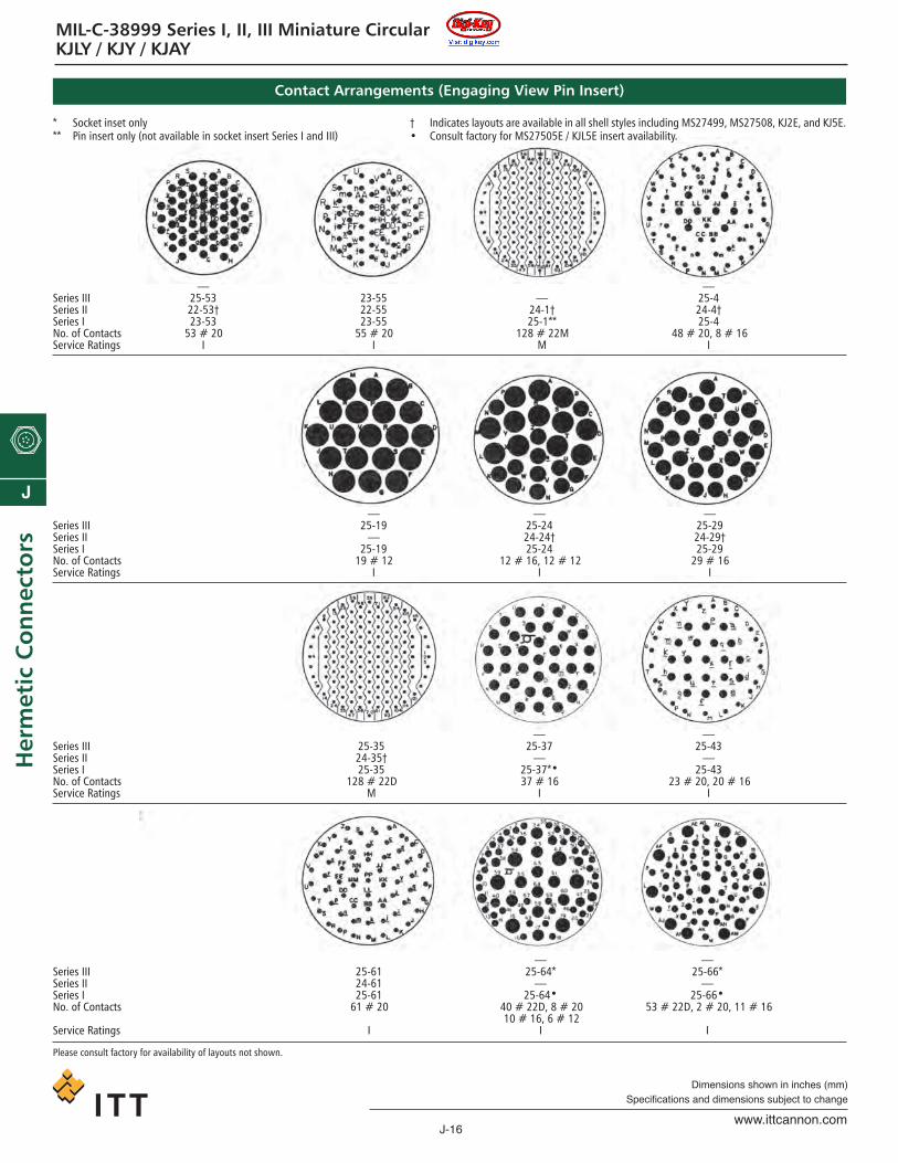
Contact Arrangements (Engaging View Pin Insert)
* Socket inset only** Pin insert only (not available in socket insert Series I and III)
† Indicates layouts are available in all shell styles including MS27499, MS27508, KJ2E, and KJ5E.• Consult factory for MS27505E / KJL5E insert availability.
Series III X 9-98 9-35 — 11-5 — 11-98 — 11-35 — — 13-8Series II 8-6† 9-98† 8-35† — 10-5† 10-13† 10-98† 10-99† 10-35† 12-3 12-4† 12-8†Series I 9-6** 9-98 9-35 11-4 11-5 11-13** 11-98 11-99** 11-35 — 13-4** 13-8No. of Contacts 6 # 22M 3 # 20 6 # 22D 4 # 20 5 # 20 13 # 22M 6 # 20 7 # 20 13 # 22D 3 # 16 4 # 16 8 # 20Service Ratings M I M I I M I I M II I I
Series III 13-98 13-35 15-5 15-15 15-18 15-19 15-35Series II 12-98† 12-35† 14-5† 14-15† 14-18† — 14-35†Series I 13-98 13-35 15-5 15-15 15-18 15-19 15-35No. of Contacts 10 # 20 22 # 22D 5 # 16 14 # 20, 1 # 16 18 # 20 19 # 20 37 # 22DService Ratings I M II I I I M
Series III 15-97 17-6 17-8 17-26 17-35 — —Series II 14-97† 16-6 16-8† 16-26† 16-35† 16-42† 16-99†Series I 15-97 17-6 17-8 17-26 17-35 — 17-99**No. of Contacts 8 # 20, 4 # 16 6 # 12 8 # 16 26 # 20 55 # 22D 42 # 22 21 # 20, 2 # 16Service Ratings I I II I M M I
Series III — — 19-11 19-32 19-35Series II 18-28 18-30 18-11 18-32† 18-35†Series I 19-28** 19-30** 19-11 19-32 19-35No. of Contacts 26 # 20, 2 # 16 29 # 20, 1 # 16 11 # 16 32 # 20 66 # 22DService Ratings I I II I M
Series III — — 21-11 21-16 21-35 21-39 21-41Series II 20-1† 20-2† — 20-16† 20-35† 20-39† 20-41†Series I 21-1** — 21-11 21-16 21-35 21-39 21-41No. of Contacts 79 # 22M 65 # 22 11 # 12 16 # 16 79 # 22D 37 # 20, 2 # 16 41- # 20Service Ratings M M I II M I I
Series III — — 23-31 — 23-35Series II 22-1† 22-2† 22-21 23-32 22-35†Series I 23-1** 23-2** 23-21 23-32** 23-35No. of Contacts 100 # 22M 85 # 22 21 # 16 32 # 20 100 # 22DService Ratings M M II I M
Please consult factory for availability of layouts not shown.
ca_J1-J50.qxd:Layout 1 2/10/11 8:51 AM Page 15
J-16www.ittcannon.com
Dimensions shown in inches (mm)Specifications and dimensions subject to change
J
Her
met
ic C
on
nec
tors
MIL-C-38999 Series I, II, III Miniature CircularKJLY / KJY / KJAY
Contact Arrangements (Engaging View Pin Insert)
* Socket inset only** Pin insert only (not available in socket insert Series I and III)
† Indicates layouts are available in all shell styles including MS27499, MS27508, KJ2E, and KJ5E.• Consult factory for MS27505E / KJL5E insert availability.
— —Series III 25-53 23-55 — 25-4Series II 22-53† 22-55 24-1† 24-4†Series I 23-53 23-55 25-1** 25-4No. of Contacts 53 # 20 55 # 20 128 # 22M 48 # 20, 8 # 16Service Ratings I I M I
— — —Series III 25-19 25-24 25-29Series II — 24-24† 24-29†Series I 25-19 25-24 25-29No. of Contacts 19 # 12 12 # 16, 12 # 12 29 # 16Service Ratings I I I
— —Series III 25-35 25-37 25-43Series II 24-35† — —Series I 25-35 25-37*• 25-43No. of Contacts 128 # 22D 37 # 16 23 # 20, 20 # 16Service Ratings M I I
— —Series III 25-61 25-64* 25-66*Series II 24-61 — —Series I 25-61 25-64• 25-66•No. of Contacts 61 # 20 40 # 22D, 8 # 20 53 # 22D, 2 # 20, 11 # 16
10 # 16, 6 # 12Service Ratings I I I
Please consult factory for availability of layouts not shown.
ca_J1-J50.qxd:Layout 1 2/10/11 8:51 AM Page 16
J-17www.ittcannon.com
Dimensions shown in inches (mm)Specifications and dimensions subject to change
J
Herm
etic Co
nn
ectors
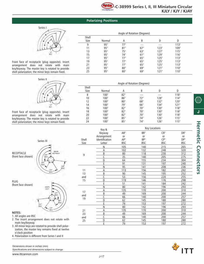
MIL-C-38999 Series I, II, III Miniature CircularKJLY / KJY / KJAY
Front face of receptacle (plug opposite). Insertarrangement does not rotate with mainkey/keyway. The master key is rotated to provideshell polarization; the minor keys remain fixed.
Front face of receptacle (plug opposite). Insertarrangement does not rotate with mainkey/keyway. The master key is rotated to provideshell polarization; the minor keys remain fixed.
NOTES:1. All angles are BSC2. The insert arrangement does not rotate with
main key/keyway3. All minor keys are rotated to provide shell polar-
ization, the master key remains fixed at twelve o’clock position
4. Polarization is different from Series I and II
PLUG(front face shown)
Series I
Series II
Series III
RECEPTACLE(front face shown)
Angle of Rotation (Degrees)ShellSize Normal A B D D
9 95° 77° — — 113°11 95° 81° 67° 123° 109°13 95° 75° 63° 127° 115°15 95° 74° 61° 129° 116°17 95° 77° 65° 125° 113°19 95° 77° 65° 125° 113°21 95° 77° 65° 125° 113°23 95° 80° 69° 121° 110°25 95° 80° 69° 121° 110°
Angle of Rotation (Degrees)ShellSize Normal A B D D
8 100° 82° — — 118°10 100° 86° 72° 128° 114°12 100° 80° 68° 132° 120°14 100° 79° 66° 134° 121°16 100° 82° 70° 130° 118°18 100° 82° 70° 130° 118°20 100° 82° 70° 130° 118°22 100° 85° 74° 126° 115°24 100° 85° 74° 126° 115°
ShellSize
9
1113and15
17and19
2123and25
Key &Keyway
ArrangementIdentification
LetterNABCDENABCDENABCDENABCDE
AR°or
AP°BSC105102803564919511390531195180135496662798013549666279
BR°or
BP°BSC140132118140155131141156145156146141142170169140145153142170169140145153
CR°or
CP°BSC215248230205234197208182195220176184196200200200180197196200200200180197
DR°or
DP°BSC265320312275304240236292252255298242293310244257280272293310244257280272
Key Locations
Polarizing Positions
ca_J1-J50.qxd:Layout 1 2/10/11 8:51 AM Page 17

J-18www.ittcannon.com
Dimensions shown in inches (mm)Specifications and dimensions subject to change
J
Her
met
ic C
on
nec
tors
MIL-C-38999 Series I, II, III Miniature CircularKJLY / KJY / KJAY
How to Order
KJL 7 Y C 17 E 35 P NSERIES PREFIXSHELL STYLECLASSCONTACT TERMINATIONSHELL SIZESHELL/HARDWARE FINISHCONTACT ARRANGEMENTCONTACT STYLESHELL POSITION
ITT Cannon Nomenclature
SERIES PREFIXKJLY — Series I - Scoop proof
SHELL STYLE0 — Wall Mounting Receptacle1 — Solder mounting7 — Jam nut mounting
CLASSY — Hermetic
CONTACT TERMINATIONC — Crimp Version; Series I only
(see pages 10-11 for availablearrangements)
No Designator — Standard connectorwith solder pot contacts
SHELL SIZE9, 11, 13, 15, 17, 19, 21, 23 and 25
HARDWARE FINISH STANDARDD — Fused tin -85°F to +302°F (-65°C to
+150°C). Jam Nut finish is cad-mium/nickel.
E — Stainless Steel -85°F to +392°F (-65°C to +200°C). Jam Nut finish ispassivated.
CONTACT ARRANGEMENTSSee pages J-15 to J-16.
CONTACT TYPEP — Pin; all contacts are gold plated.
ALTERNATE SHELL POSITIONA, B, C, and D (not required for normal). Seepage J-17.
MS27*** Y 17 E 35 P AMS NUMBER SHELL STYLECLASSSHELL SIZESHELL / HARDWARE SIZECONTACT ARRANGEMENTCONTACT STYLEALTERNATE SHELL POSITION
Military Nomenclature
MS NUMBER SHELL STYLEMS27469 – Wall MountMS27470 – Jam Nut MountMS27471 – Solder Mount
CLASSY — Hermetic
SHELL SIZE9, 11, 13, 15, 17, 19, 21, 23 and 25
HARDWARE FINISH STANDARDD — Fused tin -85°F to +302°F (-65°C to
+150°C). Jam Nut finish is cad-mium/nickel.
E — Stainless Steel -85°F to +392°F (-65°C to +200°C). Jam Nut finish ispassivated.
CONTACT ARRANGEMENTSSee pages J-15 to J-16.
CONTACT STYLEP — Pin; all contacts are gold plated.
ALTERNATE SHELL POSITIONA, B, C, and D (not required for normal). Seepage J-17.
ca_J1-J50.qxd:Layout 1 2/10/11 8:51 AM Page 18
J-19www.ittcannon.com
Dimensions shown in inches (mm)Specifications and dimensions subject to change
J
Herm
etic Co
nn
ectors
MIL-C-38999 Series I Miniature CircularKJLY
ShellSize
91113151719212325
Wall Mount
AMax.
.573 (14.55)
.701 (17.81)
.851 (21.62)
.976 (24.79)1.101 (27.97)1.208 (30.68)1.333 (33.86)1.458 (37.03)1.583 (40.21)
HMax.
.093 (2.36)
.093 (2.36)
.093 (2.36)
.093 (2.36)
.093 (2.36)
.093 (2.36)
.093 (2.36)
.093 (2.36)
.093 (2.36)
JMax.
.662 (16.81)
.810 (20.57)
.960 (24.38)1.085 (27.56)1.210 (30.73)1.317 (33.45)1.442 (36.63)1.567 (39.80)1.692 (42.98)
LMax.
.690 (17.53)
.690 (17.53)
.690 (17.53)
.690 (17.53)
.690 (17.53)
.690 (17.53)
.690 (17.53)
.690 (17.53)
.690 (17.53)
M± 0.16
.938 (23.83)1.031 (26.19)1.125 (28.58)1.219 (30.96)1.312 (33.32)1.438 (36.53)1.562 (39.67)1.688 (42.88)1.812 (46.02)
N± .005
.719 (18.26)
.812 (20.62)
.906 (23.01)
.969 (24.62)1.062 (26.97)1.156 (29.36)1.250 (31.75)1.375 (34.92)1.500 (38.10)
PMax.
.138 (3.51)
.138 (3.51)
.138 (3.51)
.138 (3.51)
.138 (3.51)
.138 (3.51)
.138 (3.51)
.157 (3.99)
.157 (3.99)
T Thread
.6875-24 UNEF-2A
.8125-20 UNEF-2A
.9375-20 UNEF-2A1.0625-18 UNEF-2A1.1875-18 UNEF-2A1.3125-18 UNEF-2A1.4375-18 UNEF-2A1.5625-18 UNEF-2A1.6875-18 UNEF-2A
U
.250 (6.35)
.250 (6.35)
.250 (6.35)
.250 (6.35)
.250 (6.35)
.250 (6.35)
.250 (6.35)
.250 (6.35)
.250 (6.35)
Solder Mount
ShellSize
91113151719212325
AMax.
.573 (14.55)
.701 (17.81)
.851 (21.62)
.976 (24.79)1.101 (27.97)1.208 (30.68)1.333 (33.86)1.458 (37.03)1.583 (40.21)
DMax.
.673 (17.09)
.782 (19.86)
.907 (23.04)1.032 (26.21)1.157 (29.39)1.251 (31.78)1.376 (34.95)1.501 (38.13)1.626 (41.30)
GMax.
.766 (19.46)
.860 (21.84)
.985 (25.02)1.111 (28.22)1.234 (31.34)1.328 (33.73)1.454 (36.93)1.579 (40.11)1.704 (43.28)
JMax.
.497 (12.62)
.625 (15.88)
.774 (19.66)
.899 (28.83)1.024 (26.01)1.129 (26.68)1.254 (31.85)1.379 (35.03)1.504 (38.20)
K± 0.16
.047 (1.19)
.047 (1.19)
.047 (1.19)
.047 (1.19)
.047 (1.19)
.047 (1.19)
.047 (1.19)
.047 (1.19)
.047 (1.19)
L± .005
.924 (23.47)
.924 (23.47)
.924 (23.47)
.924 (23.47)
.924 (23.47)
.924 (23.47)
.924 (23.47)
.924 (23.47)
.924 (23.47)
MMax.
.690 (17.53)
.690 (17.53)
.690 (17.53)
.690 (17.53)
.690 (17.53)
.690 (17.53)
.690 (17.53)
.690 (17.53)
.690 (17.53)
MS27469 KJL0Y
MS27471 KJL1Y
ca_J1-J50.qxd:Layout 1 2/10/11 8:51 AM Page 19

J-20www.ittcannon.com
Dimensions shown in inches (mm)Specifications and dimensions subject to change
J
Her
met
ic C
on
nec
tors
MIL-C-38999 Series I Miniature CircularKJLY
ShellSize
91113151719212325
Jam Nut Mount
AMax.
.653 (16.59)
.777 (19.74)
.903 (22.94)1.029 (26.14)1.153 (29.28)1.279 (32.49)1.403 (35.64)1.529 (38.84)1.653 (41.99)
BMax.
.613 (15.59)
.737 (18.72)
.863 (21.92)
.989 (25.13)1.113 (28.27)1.239 (31.47)1.363 (24.62)1.489 (37.82)1.613 (40.97)
CMax.
.655 (16.64)
.755 (19.18)
.942 (23.93)1.066 (27.08)1.191 (30.25)1.316 (33.43)1.441 (36.60)1.566 (39.78)1.691 (42.95)
DMax.
.573 (14.55)
.701 (17.81)
.851 (21.62)
.976 (24.79)1.101 (27.97)1.208 (30.68)1.333 (33.86)1.458 (37.03)1.583 (40.21)
JMax.
.497 (12.62)
.625 (15.88)
.774 (19.66)
.899 (22.83)1.024 (26.01)1.129 (28.68)1.254 (31.85)1.379 (35.03)1.504 (38.20)
SMax.
1.204 (30.58)1.391 (35.33)1.516 (38.51)1.641 (41.68)1.766 (44.86)1.954 (49.63)2.078 (52.78)2.204 (55.98)2.328 (59.13)
TMax.
.892 (22.66)1.017 (25.83)1.205 (30.61)1.329 (33.76)1.455 (36.96)1.579 (40.11)1.705 (43.31)1.829 (46.46)2.017 (51.23)
Solder Mount
T Thread
.6875-24 UNEF-2A
.8125-20 UNEF-2A1.000-20 UNEF-2A1.125-18 UNEF-2A1.250-18 UNEF-2A1.375-18 UNEF-2A1.500-18 UNEF-2A1.625-18 UNEF-2A1.750-18 UNS-2A
ShellSize
91113151719212325
AMax.
.569 (14.45)
.696 (17.68)
.810 (20.57)
.936 (23.77)1.062 (26.97)1.160 (29.46)1.285 (32.64)1.410 (35.81)1.535 (38.99)
BMax.
.573 (14.55)
.701 (17.81)
.851 (21.62)
.976 (24.79)1.101 (27.97)1.208 (30.68)1.333 (33.86)1.458 (37.03)1.583 (40.21)
HMax.
.125 (3.18)
.125 (3.18)
.125 (3.18)
.125 (3.18)
.125 (3.18)
.156 (3.96)
.156 (3.96)
.156 (3.96)
.156 (3.96)
JMax.
.497 (12.62)
.625 (15.88)
.774 (19.66)
.899 (28.83)1.024 (26.01)1.129 (26.68)1.254 (31.85)1.379 (35.03)1.504 (38.20)
LMax.
1.98 (50.29)1.44 (36.58)1.44 (36.58)1.44 (36.58)1.44 (36.58)1.44 (36.58)1.44 (36.58)1.44 (36.58)1.44 (36.58)
SMax.
1.204 (30.58)1.391 (35.33)1.516 (38.51)1.641 (41.68)1.766 (44.86)1.954 (49.63)2.078 (52.78)2.204 (55.98)2.328 (59.13)
T
.892 (22.66)1.017 (25.83)1.205 (30.61)1.329 (33.76)1.455 (36.96)1.579 (40.11)1.705 (43.31)1.829 (46.46)2.017 (51.23)
V Thread
.6875-24 UNEF-2A
.8125-20 UNEF-2A1.0000-20 UNEF-2A1.1250-18 UNEF-2A1.2500-18 UNEF-2A1.3750-18 UNEF-2A1.5000-18 UNEF-2A1.6250-18 UNEF-2A1.7500-18 UNS-2A
MS27470 KJL7Y
Crimp Version(No MS designator)
KJL7YC
ca_J1-J50.qxd:Layout 1 2/10/11 8:51 AM Page 20
J-21www.ittcannon.com
Dimensions shown in inches (mm)Specifications and dimensions subject to change
J
Herm
etic Co
nn
ectors
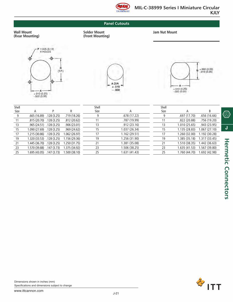
MIL-C-38999 Series I Miniature CircularKJLY
Panel Cutouts
ShellSize
91113151719212325
A.665 (16.89).815 (20.70).965 (24.51)
1.090 (27.69)1.215 (30.86)1.320 (33.53)1.445 (36.70)1.570 (39.88)1.695 (43.05)
P.128 (3.25).128 (3.25).128 (3.25).128 (3.25).128 (3.25).128 (3.25).128 (3.25).147 (3.73).147 (3.73)
R.719 (18.26).812 (20.62).906 (23.01).969 (24.62)
1.062 (26.97)1.156 (29.36)1.250 (31.75)1.375 (34.92)1.500 (38.10)
ShellSize
91113151719212325
A.697 (17.70).822 (20.88)
1.010 (25.65)1.135 (28.83)1.260 (32.00)1.385 (35.18)1.510 (38.35)1.635 (41.53)1.760 (44.70)
B.656 (16.66).756 (19.20).943 (23.95)
1.067 (27.10)1.192 (30.28)1.317 (33.45)1.442 (36.63)1.567 (39.80)1.692 (42.98)
ShellSize
91113151719212325
A.678 (17.22).787 (19.99).912 (23.16)
1.037 (26.34)1.162 (29.51)1.256 (31.90)1.381 (35.08)1.506 (38.25)1.631 (41.43)
Wall Mount(Rear Mounting)
Solder Mount(Front Mounting)
Jam Nut Mount
ca_J1-J50.qxd:Layout 1 2/10/11 8:51 AM Page 21
J-22www.ittcannon.com
Dimensions shown in inches (mm)Specifications and dimensions subject to change
J
Her
met
ic C
on
nec
tors
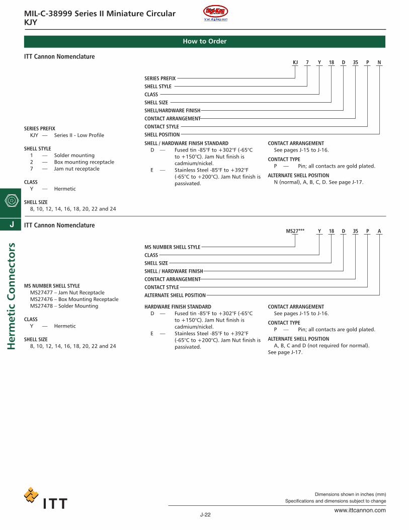
MIL-C-38999 Series II Miniature CircularKJY
KJ 7 Y 18 D 35 P N
SERIES PREFIXSHELL STYLECLASSSHELL SIZESHELL/HARDWARE FINISHCONTACT ARRANGEMENTCONTACT STYLESHELL POSITION
ITT Cannon Nomenclature
SERIES PREFIXKJY — Series II - Low Profile
SHELL STYLE1 — Solder mounting2 — Box mounting receptacle7 — Jam nut receptacle
CLASSY — Hermetic
SHELL SIZE8, 10, 12, 14, 16, 18, 20, 22 and 24
SHELL / HARDWARE FINISH STANDARDD — Fused tin -85°F to +302°F (-65°C
to +150°C). Jam Nut finish is cadmium/nickel.
E — Stainless Steel -85°F to +392°F (-65°C to +200°C). Jam Nut finish ispassivated.
CONTACT ARRANGEMENTSee pages J-15 to J-16.
CONTACT TYPEP — Pin; all contacts are gold plated.
ALTERNATE SHELL POSITIONN (normal), A, B, C, D. See page J-17.
How to Order
MS27*** Y 18 D 35 P A
MS NUMBER SHELL STYLECLASSSHELL SIZESHELL / HARDWARE FINISHCONTACT ARRANGEMENTCONTACT STYLEALTERNATE SHELL POSITION
ITT Cannon Nomenclature
MS NUMBER SHELL STYLEMS27477 – Jam Nut ReceptacleMS27476 – Box Mounting ReceptacleMS27478 – Solder Mounting
CLASSY — Hermetic
SHELL SIZE8, 10, 12, 14, 16, 18, 20, 22 and 24
HARDWARE FINISH STANDARDD — Fused tin -85°F to +302°F (-65°C
to +150°C). Jam Nut finish is cadmium/nickel.
E — Stainless Steel -85°F to +392°F (-65°C to +200°C). Jam Nut finish ispassivated.
CONTACT ARRANGEMENTSee pages J-15 to J-16.
CONTACT TYPEP — Pin; all contacts are gold plated.
ALTERNATE SHELL POSITIONA, B, C and D (not required for normal).
See page J-17.
ca_J1-J50.qxd:Layout 1 2/10/11 8:51 AM Page 22

J-23www.ittcannon.com
Dimensions shown in inches (mm)Specifications and dimensions subject to change
J
Herm
etic Co
nn
ectors
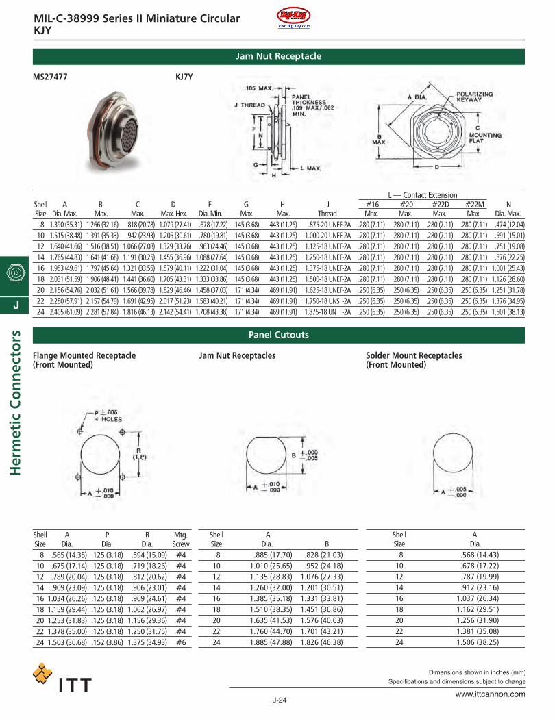
MIL-C-38999 Series II Miniature CircularKJY
DDia. Max..698 (17.73).808 (20.52).917 (23.29)
1.042 (26.47)1.167 (29.64)1.292 (32.82)1.386 (35.20)1.511 (38.38)1.636 (41.55)
EDia. Max..563 (14.30).673 (17.09).782 (19.86).907 (23.04)
1.032 (26.21)1.157 (29.39)1.251 (31.78)1.376 (34.95)1.501 (38.13)
#16.375 (9.52).375 (9.52).375 (9.52).375 (9.52).375 (9.52).375 (9.52).375 (9.52).375 (9.52).375 (9.52)
#20.375 (9.52).375 (9.52).375 (9.52).375 (9.52).375 (9.52).375 (9.52).375 (9.52).375 (9.52).375 (9.52)
#22D.375 (9.52).375 (9.52).375 (9.52).375 (9.52).375 (9.52).375 (9.52).375 (9.52).375 (9.52).375 (9.52)
#22M.375 (9.52).375 (9.52).375 (9.52).375 (9.52).375 (9.52).375 (9.52).375 (9.52).375 (9.52).375 (9.52)
G Max.
.089 (2.26)
.089 (2.26)
.089 (2.26)
.089 (2.26)
.089 (2.26)
.089 (2.26)
.089 (2.26)
.118 (3.00)
.118 (3.00)
N Dia. Max.
.474 (12.04)
.591 (15.01)
.751 (19.08)
.876 (22.25)1.001 (25.43)1.126 (28.60)1.251 (31.78)1.376 (34.95)1.501 (38.13)
Solder Mounting Receptacle
ShellSize
81012141618202224
F — Contact Extension
ADia. Max..563 (14.30).673 (17.09).782 (19.86).907 (23.04)
1.032 (26.21)1.157 (29.39)1.251 (31.78)1.376 (34.95)1.501 (38.13)
B Max.
.057 (1.45)
.057 (1.45)
.057 (1.45)
.057 (1.45)
.057 (1.45)
.057 (1.45)
.057 (1.45)
.086 (2.18)
.086 (2.18)
#16.344 (8.74).344 (8.74).344 (8.74).344 (8.74).344 (8.74).344 (8.74).344 (8.74).344 (8.74).344 (8.74)
#16.344 (8.74).344 (8.74).344 (8.74).344 (8.74).344 (8.74).344 (8.74).344 (8.74).344 (8.74).344 (8.74)
#16.344 (8.74).344 (8.74).344 (8.74).344 (8.74).344 (8.74).344 (8.74).344 (8.74).344 (8.74).344 (8.74)
#16.344 (8.74).344 (8.74).344 (8.74).344 (8.74).344 (8.74).344 (8.74).344 (8.74).344 (8.74).344 (8.74)
NDia. Max..474 (12.04).591 (15.01).751 (19.08).876 (22.25)
1.001 (25.43)1.126 (28.60)1.251 (31.78)1.376 (34.95)1.501 (38.13)
V+ .005+ .010
.125 (3.18)
.125 (3.18)
.125 (3.18)
.125 (3.18)
.125 (3.18)
.125 (3.18)
.125 (3.18)
.125 (3.18)
.152 (3.86)
XMax.
.828 (21.03)
.954 (24.23)1.047 (26.59)1.141 (28.98)1.234 (31.24)1.328 (33.73)1.453 (36.91)1.578 (40.08)1.703 (43.66)
XMax.
.594 (15.09)
.719 (18.26)
.812 (20.62)
.906 (23.01)
.969 (24.61)1.062 (26.97)1.156 (29.36)1.250 (31.75)1.375 (34.92)
ShellSize
81012141618202224
C — Contact Extension
Box Mounting Receptacle
MS27478 KJ1Y
MS27476 KJ2Y
ca_J1-J50.qxd:Layout 1 2/10/11 8:51 AM Page 23
J-24www.ittcannon.com
Dimensions shown in inches (mm)Specifications and dimensions subject to change
J
Her
met
ic C
on
nec
tors
MIL-C-38999 Series II Miniature CircularKJY
Jam Nut Receptacle
MS27477 KJ7Y
ADia. Max.
1.390 (35.31)1.515 (38.48)1.640 (41.66)1.765 (44.83)1.953 (49.61)2.031 (51.59)2.156 (54.76)2.280 (57.91)2.405 (61.09)
B Max.
1.266 (32.16)1.391 (35.33)1.516 (38.51)1.641 (41.68)1.797 (45.64)1.906 (48.41)2.032 (51.61)2.157 (54.79)2.281 (57.84)
C Max.
.818 (20.78)
.942 (23.93)1.066 (27.08)1.191 (30.25)1.321 (33.55)1.441 (36.60)1.566 (39.78)1.691 (42.95)1.816 (46.13)
D Max. Hex.1.079 (27.41)1.205 (30.61)1.329 (33.76)1.455 (36.96)1.579 (40.11)1.705 (43.31)1.829 (46.46)2.017 (51.23)2.142 (54.41)
F Dia. Min..678 (17.22).780 (19.81).963 (24.46)
1.088 (27.64)1.222 (31.04)1.333 (33.86)1.458 (37.03)1.583 (40.21)1.708 (43.38)
G Max.
.145 (3.68)
.145 (3.68)
.145 (3.68)
.145 (3.68)
.145 (3.68)
.145 (3.68)
.171 (4.34)
.171 (4.34)
.171 (4.34)
H Max.
.443 (11.25)
.443 (11.25)
.443 (11.25)
.443 (11.25)
.443 (11.25)
.443 (11.25)
.469 (11.91)
.469 (11.91)
.469 (11.91)
ShellSize
81012141618202224
JThread
.875-20 UNEF-2A1.000-20 UNEF-2A1.125-18 UNEF-2A1.250-18 UNEF-2A1.375-18 UNEF-2A1.500-18 UNEF-2A1.625-18 UNEF-2A1.750-18 UNS -2A1.875-18 UN -2A
#16Max.
.280 (7.11)
.280 (7.11)
.280 (7.11)
.280 (7.11)
.280 (7.11)
.280 (7.11)
.250 (6.35)
.250 (6.35)
.250 (6.35)
#20Max.
.280 (7.11)
.280 (7.11)
.280 (7.11)
.280 (7.11)
.280 (7.11)
.280 (7.11)
.250 (6.35)
.250 (6.35)
.250 (6.35)
#22DMax.
.280 (7.11)
.280 (7.11)
.280 (7.11)
.280 (7.11)
.280 (7.11)
.280 (7.11)
.250 (6.35)
.250 (6.35)
.250 (6.35)
#22MMax.
.280 (7.11)
.280 (7.11)
.280 (7.11)
.280 (7.11)
.280 (7.11)
.280 (7.11)
.250 (6.35)
.250 (6.35)
.250 (6.35)
NDia. Max..474 (12.04).591 (15.01).751 (19.08).876 (22.25)
1.001 (25.43)1.126 (28.60)1.251 (31.78)1.376 (34.95)1.501 (38.13)
L — Contact Extension
Panel Cutouts
A Dia.
.565 (14.35)
.675 (17.14)
.789 (20.04)
.909 (23.09)1.034 (26.26)1.159 (29.44)1.253 (31.83)1.378 (35.00)1.503 (36.68)
P Dia.
.125 (3.18)
.125 (3.18)
.125 (3.18)
.125 (3.18)
.125 (3.18)
.125 (3.18)
.125 (3.18)
.125 (3.18)
.152 (3.86)
R Dia.
.594 (15.09)
.719 (18.26)
.812 (20.62)
.906 (23.01)
.969 (24.61)1.062 (26.97)1.156 (29.36)1.250 (31.75)1.375 (34.93)
ShellSize
81012141618202224
ADia.
.885 (17.70)1.010 (25.65)1.135 (28.83)1.260 (32.00)1.385 (35.18)1.510 (38.35)1.635 (41.53)1.760 (44.70)1.885 (47.88)
B.828 (21.03).952 (24.18)
1.076 (27.33)1.201 (30.51)1.331 (33.81)1.451 (36.86)1.576 (40.03)1.701 (43.21)1.826 (46.38)
ShellSize
81012141618202224
ADia.
.568 (14.43)
.678 (17.22)
.787 (19.99)
.912 (23.16)1.037 (26.34)1.162 (29.51)1.256 (31.90)1.381 (35.08)1.506 (38.25)
Flange Mounted Receptacle(Front Mounted)
Jam Nut Receptacles Solder Mount Receptacles(Front Mounted)
ShellSize
81012141618202224
Mtg.Screw#4#4#4#4#4#4#4#4#6
ca_J1-J50.qxd:Layout 1 2/10/11 8:51 AM Page 24
J-25www.ittcannon.com
Dimensions shown in inches (mm)Specifications and dimensions subject to change
J
Herm
etic Co
nn
ectors
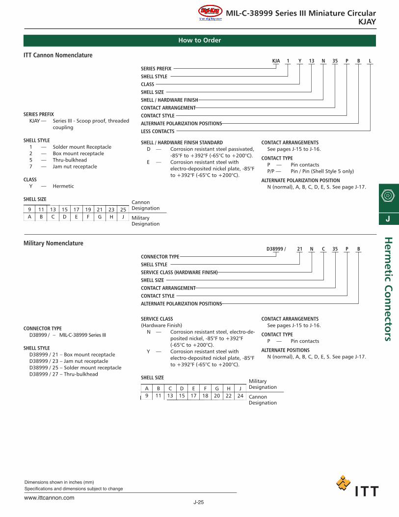
MIL-C-38999 Series III Miniature CircularKJAY
KJA 1 Y 13 N 35 P B LSERIES PREFIXSHELL STYLECLASSSHELL SIZESHELL / HARDWARE FINISHCONTACT ARRANGEMENTCONTACT STYLEALTERNATE POLARIZATION POSITIONSLESS CONTACTS
ITT Cannon Nomenclature
SERIES PREFIXKJAY — Series III - Scoop proof, threaded
coupling
SHELL STYLE1 — Solder mount Receptacle2 — Box mount receptacle5 — Thru-bulkhead7 — Jam nut receptacle
CLASSY — Hermetic
SHELL SIZE
SHELL / HARDWARE FINISH STANDARDD — Corrosion resistant steel passivated,
-85°F to +392°F (-65°C to +200°C). E — Corrosion resistant steel with
electro-deposited nickel plate, -85°Fto +392°F (-65°C to +200°C).
CONTACT ARRANGEMENTSSee pages J-15 to J-16.
CONTACT TYPEP — Pin contactsP/P — Pin / Pin (Shell Style 5 only)
ALTERNATE POLARIZATION POSITIONN (normal), A, B, C, D, E, S. See page J-17.
How to Order
9A
11B
13C
15D
17E
19F
21G
23H
25J
CannonDesignation
MilitaryDesignation
D38999 / 21 N C 35 P BCONNECTOR TYPESHELL STYLESERVICE CLASS (HARDWARE FINISH)SHELL SIZECONTACT ARRANGEMENTCONTACT STYLEALTERNATE POLARIZATION POSITIONS
Military Nomenclature
CONNECTOR TYPED38999 / – MIL-C-38999 Series III
SHELL STYLED38999 / 21 – Box mount receptacleD38999 / 23 – Jam nut receptacleD38999 / 25 – Solder mount receptacleD38999 / 27 – Thru-bulkhead
SERVICE CLASS(Hardware Finish)
N — Corrosion resistant steel, electro-de-posited nickel, -85°F to +392°F (-65°C to +200°C).
Y — Corrosion resistant steel with electro-deposited nickel plate, -85°Fto +392°F (-65°C to +200°C).
SHELL SIZE
CONTACT ARRANGEMENTSSee pages J-15 to J-16.
CONTACT TYPEP — Pin contacts
ALTERNATE POSITIONSN (normal), A, B, C, D, E, S. See page J-17.
A9
B11
C13
D15
E17
F18
G20
H22
J24
MilitaryDesignation
CannonDesignation
ca_J1-J50.qxd:Layout 1 2/10/11 8:51 AM Page 25

J-26www.ittcannon.com
Dimensions shown in inches (mm)Specifications and dimensions subject to change
J
Her
met
ic C
on
nec
tors
MIL-C-38999 Series III Miniature CircularKJAY
Box Mount Receptacle
D38999/ KJA2Y**
D38999/ KJA7Y**
ShellSize
91113151719212325
AMax.
.234 (5.94)
.234 (5.94)
.234 (5.94)
.234 (5.94)
.234 (5.94)
.234 (5.94)
.204 (5.18)
.204 (5.18)
.204 (5.18)
BDia. Max..542 (13.77).669 (16.99).800 (20.32).915 (23.24)
1.035 (26.29)1.113 (28.27)1.230 (31.24)1.376 (34.95)1.487 (37.77)
R1
.719 (18.26)
.812 (20.62)
.906 (23.01)
.969 (24.61)1.062 (26.97)1.156 (29.36)1.250 (31.75)1.375 (34.92)1.500 (38.10)
R2
.594 (15.09)
.719 (18.26)
.812 (20.62)
.906 (23.01)
.969 (24.61)1.062 (26.97)1.156 (29.36)1.250 (31.75)1.375 (34.92)
S± 0.16
1.935 (23.75)1.030 (26.16)1.124 (28.55)1.219 (30.96)1.309 (33.25)1.435 (36.45)1.561 (39.65)1.687 (42.85)1.809 (45.95)
T+ .005 –.000(+.010 –.005)
.126 (3.25)
.126 (3.25)
.126 (3.25)
.126 (3.25)
.126 (3.25)
.126 (3.25)
.126 (3.25)
.152 (3.91)
.152 (3.91)
TT+ .004 –.002(+.10 –.05).216 (5.49).194 (4.93).194 (4.93).173 (4.39).194 (4.93).194 (4.93).194 (4.93).242 (6.15).242 (6.15)
ShellSize
91113151719212325
*Modified Major Diameter (31.95—31.80)**“G” diameter and “D” Thread Major Diameter are common surfaces on shell sizes 17, 19 and 21, and there will be no step.
ADia. Max.
1.200 (30.48)1.385 (35.18)1.511 (38.38)1.637 (41.58)1.763 (44.78)1.948 (49.48)2.074 (52.68)2.200 (55.88)2.322 (58.98)
BMax.
.875 (22.22)
.875 (22.22)
.883 (22.43)
.883 (22.43)
.883 (22.43)
.883 (22.43)
.883 (22.43)
.883 (22.43)
.883 (22.43)
CFlat Max.
1.654 (16.61)1.754 (19.51)1.941 (23.90)1.065 (27.05)1.190 (30.23)1.315 (33.40)1.440 (36.58)1.565 (39.75)1.690 (42.93)
DMetric Thread
M17x1-6g0.100M20x1-6g0.100M25x1-6g0.100M28x1-6g0.100M32x1-6g0.100*M35x1-6g0.100M38x1-6g0.100M41x1-6g0.100M44x1-6g0.100
EDim. Max.
1.078 (27.38)1.267 (32.18)1.389 (35.28)1.515 (38.48)1.641 (41.68)1.826 (46.38)1.952 (49.58)2.078 (52.78)2.204 (55.98)
FMax.
1.878 (22.30)1.003 (25.48)1.191 (30.25)1.315 (33.40)1.441 (36.60)1.565 (39.75)1.691 (42.95)1.815 (46.10)2.003 (50.87)
GDia. Max.
1.688 (17.48)1.814 (20.68)1.003 (25.48)1.125 (28.58)
** **** **** **
1.625 (41.28)1.751 (44.48)
FMax.
1.6250-0 1P-0.3L-TS1.7500-0 1P-0.3L-TS1.8750-0 1P-0.3L-TS1.0000-0 1P-0.3L-TS1.1875-0 1P-0.3L-TS1.2500-0 1P-0.3L-TS1.3750-0 1P-0.3L-TS1.5000-0 1P-0.3L-TS1.6250-0 1P-0.3L-TS
Box Mount Receptacle
ca_J1-J50.qxd:Layout 1 2/10/11 8:51 AM Page 26
J-27www.ittcannon.com
Dimensions shown in inches (mm)Specifications and dimensions subject to change
J
Herm
etic Co
nn
ectors
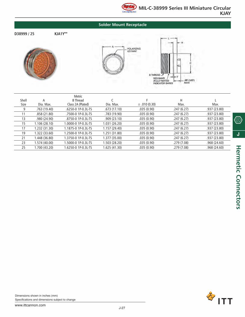
MIL-C-38999 Series III Miniature CircularKJAY
ShellSize
91113151719212325
ADia. Max.
1.763 (19.40)1.858 (21.80)1.980 (24.90)1.106 (28.10)1.232 (31.30)1.322 (33.60)1.448 (36.80)1.574 (40.00)1.700 (43.20)
MetricB Thread
Class 2A (Plated)1.6250-0 1P-0.3L-TS1.7500-0 1P-0.3L-TS1.8750-0 1P-0.3L-TS1.0000-0 1P-0.3L-TS1.1875-0 1P-0.3L-TS1.2500-0 1P-0.3L-TS1.3750-0 1P-0.3L-TS1.5000-0 1P-0.3L-TS1.6250-0 1P-0.3L-TS
CDia. Max.
1.673 (17.10)1.783 (19.90)1.909 (23.10)1.031 (26.20)1.157 (29.40)1.251 (31.80)1.377 (35.00)1.503 (28.20)1.625 (41.30)
F± .010 (0.30).035 (0.90).035 (0.90).035 (0.90).035 (0.90).035 (0.90).035 (0.90).035 (0.90).035 (0.90).035 (0.90)
HMax.
.247 (6.27)
.247 (6.27)
.247 (6.27)
.247 (6.27)
.247 (6.27)
.247 (6.27)
.247 (6.27)
.279 (7.08)
.279 (7.08)
LMax.
.937 (23.80)
.937 (23.80)
.937 (23.80)
.937 (23.80)
.937 (23.80)
.937 (23.80)
.937 (23.80)
.968 (24.60)
.968 (24.60)
D38999 / 25 KJA1Y**
Solder Mount Receptacle
ca_J1-J50.qxd:Layout 1 2/10/11 8:51 AM Page 27
J-28www.ittcannon.com
Dimensions shown in inches (mm)Specifications and dimensions subject to change
J
Her
met
ic C
on
nec
tors
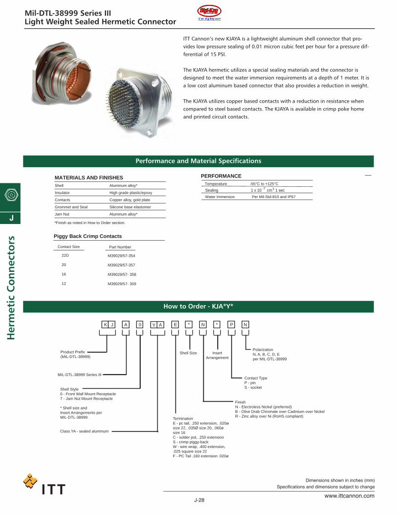
Mil-DTL-38999 Series IIILight Weight Sealed Hermetic Connector
NP *N*E0 A J K
Product Prefix (MIL-DTL-38999)
MIL-DTL-38999 Series III
FinishN - Electroless Nickel (preferred)B - Olive Drab Chromate over Cadmium over NickelR - Zinc alloy over Ni (RoHS compliant)
Contact TypeP - pinS - socket
PolarizationN, A, B, C, D, Eper MIL-DTL-38999
Shell Style0 - Front Wall Mount Receptacle7 - Jam Nut Mount Receptacle
* Shell size and Insert Arrangements per MIL-DTL-38999. Termination
E - pc tail, .250 extension, .020ø size 22, .035Ø size 20, .060ø size 16C - solder pot, .250 extensionS - crimp piggy-backW - wire wrap, .400 extension, .025 square size 22F - PC Tail .160 extension .020ø
Shell Size Insert Arrangement
Y A
Class YA - sealed aluminum
ITT Cannon’s new KJAYA is a lightweight aluminum shell connector that pro-vides low pressure sealing of 0.01 micron cubic feet per hour for a pressure dif-ferential of 15 PSI.
The KJAYA hermetic utilizes a special sealing materials and the connector is designed to meet the water immersion requirements at a depth of 1 meter. It isa low cost aluminum based connector that also provides a reduction in weight.
The KJAYA utilizes copper based contacts with a reduction in resistance whencompared to steel based contacts. The KJAYA is available in crimp poke homeand printed circuit contacts.
Shell
Insulator
Contacts
Grommet and Seal
Jam Nut
*Finish as noted in How to Order section.
Aluminum alloy*
High grade plastic/epoxy
Copper alloy, gold plate
Silicone base elastomer
Aluminum alloy*
PERFORMANCEMATERIALS AND FINISHESTemperature -55°C to +125°C
Sealing 1 x 10 cm 1 sec3-7
Contact Size Part Number
Piggy Back Crimp Contacts
22D
20
16
12
M39029/57-354
M39029/57-357
M39029/57- 358
M39029/57- 359
Water Immersion Per Mil-Std-810 and IP67
Performance and Material Specifications
How to Order - KJA*Y*
ca_J1-J50.qxd:Layout 1 2/10/11 8:51 AM Page 28
J-29www.ittcannon.com
Dimensions shown in inches (mm)Specifications and dimensions subject to change
J
Herm
etic Co
nn
ectors
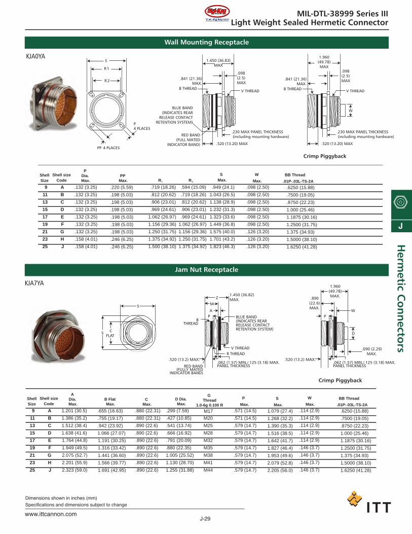
MIL-DTL-38999 Series IIILight Weight Sealed Hermetic Connector
Wall Mounting Receptacle
.098(2.5)MAX
R 1
R 2
1.450 (36.83)MAX
V THREAD
.841 (21.36)MAX.
B THREAD
S
P4 PLACES
.520 (13.20) MAX
BLUE BAND(INDICATES REAR
RELEASE CONTACTRETENTION SYSTEM)
PP 4 PLACES
RED BAND(FULL MATED
INDICATOR BAND)
.230 MAX PANEL THICKNESS(including mounting hardware)
1.960(49.78)MAX
.098(2.5)MAX
V THREAD
.520 (13.20) MAX
.230 MAX PANEL THICKNESS(including mounting hardware)
W
.841 (21.36)MAX.
B THREAD
Crimp Piggyback
KJA0YA
V THREADR THREAD
.520 (13.2) MAX..062 (1.57) MIN./.125 (3.18) MAX.PANEL THICKNESS
S
Z
A
M
PB
THREAD
S CFLAT
BLUE BAND(INDICATES REARRELEASE CONTACTRETENTION SYSTEM)
RED BAND(FULLY MATED
INDICATOR BAND)
1.450 (36.82)MAX.
.520 (13.2) MAX..062 (1.57) MIN./.125 (3.18) MAX.PANEL THICKNESS
WP
1.960(49.78)MAX..890
(22.6)MAX.
D
.090 (2.29)MAX.
Crimp Piggyback
KJA7YA
ShellSize
Shell sizeCode
W
Max.
SMax.R 1 R 2
9
11
13
15
17
19
21
23
25
A
B
C
D
E
F
G
H
J
.719 (18.26)
.812 (20.62)
.906 (23.01)
.969 (24.61)
1.062 (26.97)
1.156 (29.36)
1.250 (31.75)
1.375 (34.92)
1.500 (38.10)
.594 (15.09)
.719 (18.26)
.812 (20.62)
.906 (23.01)
.969 (24.61)
1.062 (26.97)
1.156 (29.36)
1.250 (31.75)
1.375 (34.92)
.949 (24.1)
1.043 (26.5)
1.138 (28.9)
1.232 (31.3)
1.323 (33.6)
1.449 (36.8)
1.575 (40.0)
1.701 (43.2)
1.823 (46.3)
.098 (2.50)
.098 (2.50)
.098 (2.50)
.098 (2.50)
.098 (2.50)
.098 (2.50)
.126 (3.20)
.126 (3.20)
.126 (3.20)
P Dia. Max.
.132 (3.25)
.132 (3.25)
.132 (3.25)
.132 (3.25)
.132 (3.25)
.132 (3.25)
.132 (3.25)
.158 (4.01)
.158 (4.01)
.220 (5.59)
.198 (5.03)
.198 (5.03)
.198 (5.03)
.198 (5.03)
.198 (5.03)
.198 (5.03)
.246 (6.25)
.246 (6.25)
PP
Max.BB Thread
.01P-.03L-TS-2A
.6250 (15.88)
.7500 (19.05)
.8750 (22.23)
1.000 (25.46)
1.1875 (30.16)
1.2500 (31.75)
1.375 (34.93)
1.5000 (38.10)
1.6250 (41.28)
ShellSize
Shell sizeCode
P
Max.
G Thread
1.0-6g 0.100 R
9
11
13
15
17
19
21
23
25
A
B
C
D
E
F
G
H
J
.880 (22.31)
.880 (22.31)
.890 (22.6)
.890 (22.6)
.890 (22.6)
.890 (22.6)
.890 (22.6)
.890 (22.6)
.890 (22.6)
.299 (7.59)
.427 (10.85)
.541 (13.74)
.666 (16.92)
.791 (20.09)
.880 (22.35)
1.005 (25.52)
1.130 (28.70)
1.255 (31.88)
M17
M20
M25
M28
M32
M35
M38
M41
M44
.571 (14.5)
.571 (14.5)
.579 (14.7)
.579 (14.7)
.579 (14.7)
.579 (14.7)
.579 (14.7)
.579 (14.7)
.579 (14.7)
A Dia. Max.
1.201 (30.5)
1.386 (35.2)
1.512 (38.4)
1.638 (41.6)
1.764 (44.8)
1.949 (49.5)
2.075 (52.7)
2.201 (55.9)
2.323 (59.0)
.655 (16.63)
.755 (19.17)
.942 (23.92)
1.066 (27.07)
1.191 (30.25)
1.316 (33.42)
1.441 (36.60)
1.566 (39.77)
1.691 (42.95)
B Flat Max.
BB Thread
.01P-.03L-TS-2A
.6250 (15.88)
.7500 (19.05)
.8750 (22.23)
1.000 (25.46)
1.1875 (30.16)
1.2500 (31.75)
1.375 (34.93)
1.5000 (38.10)
1.6250 (41.28)
C
Max.
D Dia. Max.
S
Max.
1.079 (27.4)
1.268 (32.2)
1.390 (35.3)
1.516 (38.5)
1.642 (41.7)
1.827 (46.4)
1.953 (49.6)
2.079 (52.8)
2.205 (56.0)
W
Max.
.114 (2.9)
.114 (2.9)
.114 (2.9)
.114 (2.9)
.114 (2.9)
.146 (3.7)
.146 (3.7)
.146 (3.7)
.146 (3.7)
Jam Nut Receptacle
ca_J1-J50.qxd:Layout 1 2/10/11 8:51 AM Page 29
J-30www.ittcannon.com
J
Her
met
ic C
on
nec
tors
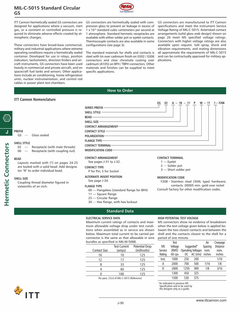
MIL-C-5015 Standard CircularGS
GS 02 A – 18 – 11 P W – 11 1 – F208SERIES PREFIXSHELL STYLEBEADSHELL SIZECONTACT ARRANGEMENTCONTACT STYLEPOLARIZATIONFLANGE TYPECONTACT TERMINALMODIFICATION CODE
ITT Cannon Nomenclature
PREFIXGS — Glass sealed
SHELL STYLE02 — Receptacle (with male threads)06 — Receptacle (with coupling nut)
BEADLayouts marked with (*) on pages 24-25are tooled with a solid bead. Add designa-tor “A” to order individual bead.
SHELL SIZECoupling thread diameter figured in sixteenths of an inch.
CONTACT ARRANGEMENTSee pages J-31 to J-32.
CONTACT TYPEP for Pin; S for Socket
ALTERNATE INSERT POSITIONSee page J-34.
FLANGE TYPE00 — Flangeless (standard flange for BFH)11 — Square flange25 — Circular flange30 — Hex flange, with hex lockout
CONTACT TERMINAL1 — Eyelet2 — Solder pot3 — Short solder pot
MODIFICATION CODEF208 – Stainless steel (304L type) hardware;
contacts .00005 min. gold over nickelConsult factory for other modification codes.
How to Order
Standard Data
ITT Cannon hermetically sealed GS connectors aredesigned for applications where a vacuum, inertgas, or a constant or controlled pressure is re-quired to eliminate adverse effects created by at-mospheric changes.
These connectors have broad-base commercial,military and industrial applications where extremeoperating conditions require a hermetically sealedcontainer. Developed for use in relays, position indicators, tachometers, direction finders and air-craft instruments, GS connectors have been usedheavily in commercial and private aircraft, and onspacecraft fuel tanks and sensors. Other applica-tions include air conditioning, home refrigerationunits, nuclear instrumentation, and control rod cables in power plant test chambers.
GS connectors are hermetically sealed with com-pression glass to prevent air leakage in excess of1 x 10-6 standard cubic centimeters per second at1 atmosphere. Standard hermetic receptacles areavailable with either solder pot or eyelet contacts.Thermocouple contacts are also available in someconfigurations (see page 3).
The standard materials for shells and contacts issteel with tin over cadmium finish on GS02 / GS06connectors and clear chromate coating over cadmium (A105) on BFH / TBFH connectors. Othermaterials and finishes can be supplied to meetspecific applications.
GS connectors are manufactured to ITT Cannonspecifications and meet the instrument ServiceVoltage Rating of MIL-C-5015. Asterisked contactarrangements (solid glass web design) shown onpage 26 meet MS specified voltage ratings. Connectors with higher voltage ratings are alsoavailable upon request. Salt spray, shock and vibration requirements, and mating dimensionsall approximate the requirements of MIL-C-5015and can be contractually approved for military ap-plications.
ELECTRICAL SERVICE DATAMaximum current ratings of contacts and maxi-mum allowable voltage drop under test condi-tions when assembled as in service are shownbelow. Maximum total current to be carried perconnector is the same as that allowable in wirebundles as specified in MIL-W-5088.
Test Current Potential DropContact Size (amps) (millivolts)
16 110 12512 117 12518 133 12514 160 12510 100 125Per para. 3.6.6 of MIL-C-5015 (Reference)
HIGH POTENTIAL TEST VOLTAGEMS connectors show no evidence of breakdownwhen the test voltage given below is applied be-tween the two closest contacts and between theshell and the contacts closest to the shell for aperiod of one minute.
Test Air CreepageMS Voltage Suggested* Spacing Distance
Service (RMS) Operating Voltages nom. nom.Rating 60 cps DC AC (rms) inches inchesInst. 1000 250 200 1/16
A 2000 700 500 1/16 1/8D 2800 1250 900 1/8 3/16
1300 450 3251500 530 375
*As indicated in previous MS Specification and to be used bythe designer only as a guide.
ca_J1-J50.qxd:Layout 1 2/10/11 8:51 AM Page 30

J-31www.ittcannon.com
Dimensions shown in inches (mm)Specifications and dimensions subject to change
J
Herm
etic Co
nn
ectors
MIL-C-5015 Standard CircularGS
Contact Arrangements
†† MS polarization†† ITT Cannon polarization†* Tooled with solid bead
Shell Size 18-9† 18-8† 18-1† 20-19† 20-24† 20-4†No. of Contacts 5-#16 (B, C, E-G) 7-#16 (A, G) 10-#16 3-#8 2-#16 (A, C) 4-#12
2-#12 (A, D) 1-#12 (H)Service Rating Inst. 1500 1300 (B, C, F, G) A 1500 2300
Inst. (all others)
Shell Size 20-16† 20-18† 20-27† 20-29† 20-33† 22-2†No. of Contacts 7-#16 (A, G) 6-#16 (A, C-E, G, H) 14-#16 17-#16 11-#16 3-#8
2-#12 (H, I) 3-#12 (B, F, I)Service Rating A 1300 1500 1300 1500 2300
Shell Size 22-9† 22-22† 22-5† 22-18† 22-23† 22-20†No. of Contacts 3-#12 4-#8 4-#16 (A, C, D, F) 8-#16 8-#12 9-#16
2-#12 (B, E)Service Rating E 2000 1500 1500 1500 1500
Shell Size 20-14† 20-8† 20-17† 20-22† 20-15† 20-7†No. of Contacts 3-#12 (C, D, E) 4-#16 (B, C, E, F) 1-#16 (F) 3-#16 (B, D, F) 7-#12 8-#16
2-#12 (A, D) 1-#12 (H)Service Rating A Inst. A 1500 1500 1500 C, D, E, F
Shell Size 8S-1 10S2 *10SL-4 *10SL-3 10SLA-4 12S-4 *12S-3† 12S-10 14S-9No. of Contacts 1- #16 1- #16 2- #16 3- #16 5- #20 1- #16 2- #16 4- #16 2- #16Service Rating A A 1300 1300 1300 D 1500 Inst. 1500
Shell Size 14S-1 14S-7† *14S-2† 14S-5† 14S-6 16S-4† 16-11† 16-10†No. of Contacts 3-#16 3-#16 4-#16 5-#16 6-#16 2-#16 2-#12 3-#12Service Rating 1500 1500 Inst. Inst. Inst. 1500 1500 1500
Shell Size 16-9† 16S-8† 16S-1† 18-4† 18-10† 18-11† 18-12†No. of Contacts 2-#16 (B, D) 5-#16 7-#16 4-#16 4-#12 5-#12 6-#16
2-#12 (A, C)Service Rating 1500 1500 1300 2300 1500 1500 1500
ca_J1-J50.qxd:Layout 1 2/10/11 8:51 AM Page 31
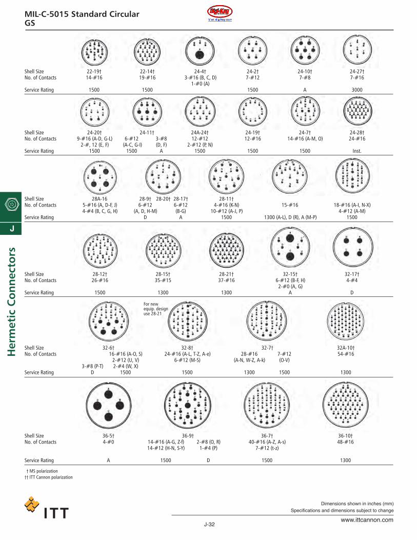
J-32www.ittcannon.com
Dimensions shown in inches (mm)Specifications and dimensions subject to change
J
Her
met
ic C
on
nec
tors
MIL-C-5015 Standard CircularGS
Shell Size 22-19† 22-14† 24-4† 24-2† 24-10† 24-27†No. of Contacts 14-#16 19-#16 3-#16 (B, C, D) 7-#12 7-#8 7-#16
1-#0 (A)Service Rating 1500 1500 1500 A 3000
Shell Size 24-20† 24-11† 24A-24† 24-19† 24-7† 24-28†No. of Contacts 9-#16 (A-D, G-L) 6-#12 3-#8 12-#12 12-#16 14-#16 (A-M, O) 24-#16
2-#, 12 (E, F) (A-C, G-I) (D, F) 2-#12 (P, N)Service Rating 1500 1500 A 1500 1500 1500 Inst.
Shell Size 28A-16 28-9† 28-20† 28-17† 28-11†No. of Contacts 5-#16 (A, D-F, J) 6-#12 6-#12 4-#16 (K-N) 15-#16 18-#16 (A-I, N-X)
4-#4 (B, C, G, H) (A, D, H-M) (B-G) 10-#12 (A-J, P) 4-#12 (A-M)Service Rating D A 1500 1300 (A-L), D (R), A (M-P) 1500
Shell Size 28-12† 28-15† 28-21† 32-15† 32-17†No. of Contacts 26-#16 35-#15 37-#16 6-#12 (B-F, H) 4-#4
2-#0 (A, G)Service Rating 1500 1300 1300 A D
For new equip. designuse 28-21
Shell Size 32-6† 32-8† 32-7† 32A-10†No. of Contacts 16-#16 (A-O, S) 24-#16 (A-L, T-Z, A-e) 28-#16 7-#12 54-#16
2-#12 (U, V) 6-#12 (M-S) (A-N, W-Z, A-k) (O-V)3-#8 (P-T) 2-#4 (W, X)
Service Rating D 1500 1500 1300 1500 1300
Shell Size 36-5† 36-9† 36-7† 36-10†No. of Contacts 4-#0 14-#16 (A-G, Z-f) 2-#8 (O, R) 40-#16 (A-Z, A-s) 48-#16
14-#12 (H-N, S-Y) 1-#4 (P) 7-#12 (t-z)
Service Rating A 1500 D 1500 1300
†† MS polarization†† ITT Cannon polarization
ca_J1-J50.qxd:Layout 1 2/10/11 8:51 AM Page 32

J-33www.ittcannon.com
Dimensions shown in inches (mm)Specifications and dimensions subject to change
J
Herm
etic Co
nn
ectors
MIL-C-5015 Standard CircularGS
Shell Sizes and Contact Arrangements
Shell sizes are based on the diameter of the cou-pling threads in sixteenths of an inch; for exam-ple, size 22 shell has a coupling thread diameterof 22/16 inch, which equals 1-3/8. In the contactarrangement section, pages 24-25 the shell sizeand contact arrangement number are shown incombination, e.g., 8S-1, 22-2 or 24-7. The digits(8S, 22 and 24) preceding the dash refer to theshell size. The digits (-1, -2 and -7) following thedash are the contact arrangement numbers.
GS02 CONTACT ARRANGEMENTS - SOCK-ETS12S-3S 18-8S 22-5S 28-17S14S-1S 18-9S 22-9S 28-20S14S-2S 18-10S 22-14S 28-21S14S-5S 18-12S 22-19S 32-7S14S-6S 20-4S 22-22S 32-8S14S-7S 20-7S 24-2S 32-15S14S-9S 20-8S 24-7S 32-17S16S-1S 20-15S 24-10S 36-5S16S-4S 20-16S 24-20S 36-7S16S-8S 20-17S 24-28S 36-10S16-9S 20-18S 28-9S 40A-27S16-10S 20-24S 28-11S16-11S 20-27S 28-12S18-1S 20-29S 28-15S18-4S 20-33S
GS02 CONTACT ARRANGEMENTS - PINS*18S-1P *18-1P *22-2P *28-11P*10S-2P *18-4P *22-5P *28-12P*10SL-3P *18-8P *22-9P *28-15P*10SL-4P *18-9P *22-14P *28-17P*10SLA4 *18-10P *22-18P *28-20P*12S-3P *18-11P *22-19P *28-21P*12S-4P *18-12P *22-20P *28-A16*12SA10 *20-4P *22-22P *32-6P*14S-1P *20-7P *22-23P *32-7P*14S-2P *20-14P *24-2P *32-8P*14S-5P *20-15P *24-7P *32-9*14S-6P *20-16P *24-10P *32-17P*14S-7P *20-17P *24-11P *32-A10*14S-9P *20-18P *24-19P *36-5P*16S-1P *20-19P *24-20P *36-7P*16S-4P *20-22P *24-22P *36-9P*16S-8p *20-24P *24-27P *36-10P*16-9P *20-27P *24-28P*16-10P *20-29P *24A24*16-11P *20-33P *28-9P*Tooled with solid bead.
GS06 CONTACT ARRANGEMENTS - PINS14S-2P 20-20P16S-1P 20-33P18-1P 22-19P18-11P 24-28P20-7P 28-21P20-15P 32-7P
Contact No. of WireArrangement Contacts SizeSHELL SIZE 8S
8S-1 1 #16SHELL SIZE 10S/10SL
10S-2 1 #1610SL-2 3 #1610SL-4 2 #1610SLA4 5 #20
SHELL SIZE 12/12S12S-3 2 #1612S-4 1 #16
Δ 12SA10 4 #16SHELL SIZE 14/14S
14S-1 3 #1614S-2 4 #1614S-5 5 #1614S-6 6 #1614S-7 3 #1614S-9 2 #16
SHELL SIZE 16/16S16S-1 7 #1616S-4 2 #1616S-8 5 #1616-9 2 #12
2 #1616S-10 3 #1216S-11 2 #12
SHELL SIZE 1818-1 10 #1618-4 4 #16
Δ Cannon proprietary arrangements
Contact No. of WireArrangement Contacts Size
18-8 1 #127 #16
18-9 2 #125 #16
18-10 4 #1218-11 5 #1218-12 6 #16
SHELL SIZE 2020-4 4 #1220-7 8 #1620-8 2 #8
4 #1620-14 2 #8
3 #1220-15 7 #1220-16 2 #12
7 #1620-17 5 #12
1 #1620-18 3 #12
6 #1620-19 3 #820-22 3 #8
3 #1620-24 2 #8
2 #1620-27 14 #1620-29 17 #1620-33 11 #16
Contact No. of WireArrangement Contacts SizeSHELL SIZE 22
22-2 3 #822-5 2 #12
4 #1622-9 3 #1222-14 19 #1622-18 8 #1622-19 14 #1622-20 9 #1622-22 4 #822-23 8 #12
SHELL SIZE 2424-2 7 #1224-4 1 #0
3 #1624-7 2 #12
14 #1624-10 7 #824-11 3 #8
6 #1224-19 12 #1624-20 2 #12
9 #1624-27 7 #1624-28 24 #16
Δ 24A-24 12 #12SHELL SIZE 28
28-9 6 #126 #16
28-11 4 #1218 #16
Contact No. of WireArrangement Contacts SizeSHELL SIZE 8S
28-12 26 #1628-15 35 #1628-17 15 #1628-20 10 #12
4 #1628-21 37 #16
Δ 28A-16 4 #45 #16
SHELL SIZE 3232-6 2 #4
3 #82 #12
16 #1632-7 7 #12
28 #1632-8 6 #12
24 #1632-15 2 #0
6 #1232-17 4 #4
Δ 32A-10 54 #16SHELL SIZE 36
36-5 4 #036-7 7 #12
40 #1636-9 1 #4
2 #814 #1214 #16
36-10 48 #16
ca_J1-J50.qxd:Layout 1 2/10/11 8:51 AM Page 33

J-34www.ittcannon.com
Dimensions shown in inches (mm)Specifications and dimensions subject to change
J
Her
met
ic C
on
nec
tors
MIL-C-5015 Standard CircularGS
Alternate Insert Positions
Each insert arrangement is shown in its normalposition in the shell.
In normal position, the indexing radius coincideswith CL of the master key or keyway of shell.
In alternate positions the pin insert is rotatedclockwise so that angle “A” between the indexingradius and the CL of the master key or keyway ofshell is as required.
In alternate positions the socket insert is rotatedcounter-clockwise so that angle “A” between theindexing radius and the CL of the master key orkeyway of shell is as required.
MS Alternate Positions
ITT Cannon Alternate Positions (Not MS approved)
ContactDegreesNo. of Arrange-
Contacts ment W X Y Z2 12S-3 70 145 215 290
14S-9 70 145 215 29016S-4 35 110 250 32516-11 35 110 250 325
3 14S-7 90 180 270 —16-10 90 180 270 —20-19 90 180 270 —22-2 70 145 215 29022-9 70 145 215 290
4 14S-2 — 120 240 —16-9 35 110 250 32518-4 35 110 250 32518-10 — 120 240 —20-4 45 110 250 —20-24 35 110 250 32522-22 — 110 250 —24-4 80 110 250 28032-17 45 110 250 —36-5 — 120 240 —
5 14S-5 — 110 — —16S-8 — 170 265 —18-11 — 170 265 —20-14 80 110 250 280
6 18-12 80 — — 28020-8 80 110 250 28020-17 90 180 270 —20-22 80 110 250 28022-5 35 110 250 325
7 16S-1 80 — — 28018-9 80 110 250 28020-15 80 — — 28024-2 80 — — 28024-10 80 — — 28024-27 80 — — 280
ContactDegreesNo. of Arrange-
Contacts ment W X Y Z8 18-8 70 — — 290
20-7 80 110 250 28022-18 80 110 250 28022-23 35 — 250 —32-15 35 110 250 280
9 20-16 80 110 250 28020-18 35 110 250 32522-20 35 110 250 32524-11 35 110 250 325
10 18-1 70 145 215 29011 24-20 80 110 250 28012 28-9 80 110 250 28014 20-27 35 110 250 325
22-19 80 110 250 28028-20 80 110 250 280
15 28-17 80 110 250 280
ContactDegreesNo. of Arrange-
Contacts ment W X Y Z16 24-7 80 110 250 28017 20-29 80 — — 28019 22-14 80 — — 28022 28-11 80 110 250 28023 32-6 80 110 250 28024 24-28 80 110 250 28026 28-12 90 180 270 —30 32-8 80 125 325 28031 36-9 80 125 325 28035 28-15 80 110 250 280
32-7 80 125 325 28037 28-21 80 110 250 28047 36-7 80 110 250 28048 36-10 80 125 235 280
Shell ContactSize Arrangement Available Position
10SL 2 3 5 8 12 1312S 3 5 8 1324 A24 2 4 9 1228 A16 2 3 5 8 9 1332 A10 2 3 4 5 8 9 12 1340 A27 4 14 17 20 22
Note: Front view of pin insulator rotated as shown.
Position Angle (deg.)Normal 0
2 2603 1104 805 use pos. 36 858 2509 280
Position Angle (deg.)11 10512 10013 use pos. 814 3015 4516 12017 13018 150
Position Angle (deg.)19 19520 22021 25522 29023 16524 33025 23526 125
ca_J1-J50.qxd:Layout 1 2/10/11 8:52 AM Page 34
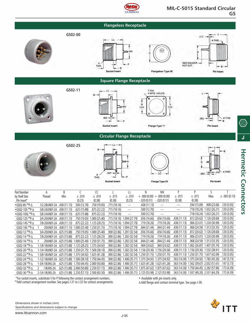
J-35www.ittcannon.com
Dimensions shown in inches (mm)Specifications and dimensions subject to change
J
Herm
etic Co
nn
ectors
MIL-C-5015 Standard CircularGS
Flangeless Receptacle
Square Flange Receptacle
Circular Flange Receptacle
Part Numberby Shell Size* Pin Insert*•GS02-8S-**P-Δ•GS02-10S-**P-Δ•GS02-10SL-**P-Δ•GS02-12S-**P-Δ•GS02-14S-**P-Δ•GS02-16S-**P-Δ•GS02-12-**P-Δ•GS02-14-**P-Δ•GS02-16-**P-Δ•GS02-18-**P-Δ•GS02-20-**P-Δ•GS02-22-**P-Δ•GS02-24-**P-Δ•GS02-28-**P-Δ•GS02-32-**P-Δ•GS02-36-**P-Δ
AThread
1/2-28UNEF-2A5/8-24UNEF-2A5/8-24UNEF-2A3/4-20UNEF-2A7/8-20UNEF-2A
1-3/4-20UNEF-2A3/4-20UNEF-2A7/8-20UNEF-2A
1-3/4-20UNEF-2A1-1/8-18UNEF-2A1-1/4-18UNEF-2A1-3/8-18UNEF-2A1-1/2-18UNEF-2A1-3/4-18UNS-2AE2-3/4-18UNS-2AE2-1/4-18UNS-2AE
BMin.
.438 (11.13)
.438 (11.13)
.438 (11.13)
.438 (11.13)
.438 (11.13)
.438 (11.13)
.625 (15.88)
.625 (15.88)
.625 (15.88)
.625 (15.88)
.625 (15.88)
.625 (15.88)
.625 (15.88)
.625 (15.88)
.625 (15.88)
.625 (15.88)
C± .010(0.25)
.500 (12.70)
.625 (15.88)
.625 (15.88)
.750 (19.05)
.875 (22.22)1.000 (25.40).750 (19.05).875 (22.22)
1.000 (25.40)1.125 (28.25)1.250 (31.75)1.375 (34.92)1.500 (38.10) 1.750 (44.45) 2.000 (50.80)2.250 (57.15)
CC± .010(0.38)
.750 (19.05)
.875 (22.22)
.875 (22.22)1.000 (25.40)1.125 (28.25)1.250 (31.75)1.000 (25.40)1.125 (28.25)1.250 (31.75)1.375 (34.92)1.500 (38.10) 1.625 (41.28)1.750 (44.45) 2.000 (50.80)2.250 (57.15)2.500 (63.50)
L± .015(0.38)
.715 (18.16)
.715 (18.16)
.715 (18.16)
.715 (18.16)
.715 (18.16)
.715 (18.16)
.900 (22.86)
.900 (22.86)
.900 (22.86)
.900 (22.86)
.900 (22.86)
.900 (22.86)
.900 (22.86)
.900 (22.86)
.900 (22.86)
.900 (22.86)
LL± .010(0.25)
———
1.094 (27.79)1.094 (27.79)1.094 (27.79)1.281 (32.54)1.282 (32.54)1.282 (32.54)1.282 (32.54)1.282 (32.54)1.282 (32.54)1.406 (35.71)1.406 (35.71)1.406 (35.71)1.406 (35.71)
N+ .000 (0.00)- .020 (0.51).438 (11.13).500 (12.70).500 (12.70).656 (16.66).719 (18.26).844 (21.44).656 (16.66).719 (18.26).844 (21.44).969 (24.62)
1.156 (29.36)1.250 (31.75)1.375 (34.92)1.625 (41.28)1.875 (47.62)2.125 (53.98)
NN+ .000 (0.00)- .020 (0.51)
———
.656 (16.66)
.719 (18.26)
.844 (21.44)
.656 (16.66)
.719 (18.26)
.844 (21.44)
.969 (24.62)1.156 (29.36)1.250 (31.75)1.375 (34.92)1.625 (41.28)1.875 (47.62)2.125 (53.98)
P± .015(0.38)
———
.438 (11.13)
.438 (11.13)
.438 (11.13)
.438 (11.13)
.438 (11.13)
.438 (11.13)
.438 (11.13)
.438 (11.13)
.438 (11.13)
.563 (14.30)
.563 (14.30)
.563 (14.30)
.563 (14.30)
P± .015(0.38)
.594 (15.09)
.718 (18.24)
.718 (18.24)
.812 (20.62)
.906 (23.01)
.968 (24.59)
.812 (20.62)
.906 (23.01)
.968 (24.59)1.062 (26.87)1.156 (29.36)1.250 (31.75)1.375 (34.92)1.562 (39.67)1.750 (44.45)1.937 (49.20)
SMax.
.908 (23.06)1.032 (26.21)1.032 (26.21)1.126 (28.60)1.220 (30.99)1.313 (33.35)1.126 (28.60)1.220 (30.99)1.313 (33.35)1.407 (35.74)1.532 (38.91)1.657 (42.09)1.782 (45.26)2.032 (51.61)2.282 (57.96)2.531 (64.29)
T± .005 (0.13)
.120 (3.05)
.120 (3.05)
.120 (3.05)
.120 (3.05)
.120 (3.05)
.120 (3.05)
.120 (3.05)
.120 (3.05)
.120 (3.05)
.120 (3.05)
.120 (3.05)
.120 (3.05)
.147 (3.73)
.147 (3.73)
.173 (4.39)
.173 (4.39)
**For socket inserts, substitute S for P following the contact arrangement numbers.**Add contact arrangement number. See pages J-31 to J-32 for contact arrangements.
• Available with pin inserts only.Δ Add flange and contact terminal type. See page J-38.
GS02-00
GS02-11
GS02-25
ca_J1-J50.qxd:Layout 1 2/10/11 8:52 AM Page 35

J-36www.ittcannon.com
Dimensions shown in inches (mm)Specifications and dimensions subject to change
J
Her
met
ic C
on
nec
tors
MIL-C-5015 Standard CircularGS
Hex Flange Receptacle
Part Numberby Shell Size* Pin Insert*•GS02-8S-**P-30Δ•GS02-10S-**P-30Δ•GS02-10SL-**P-30Δ•GS02-12S-**P-30Δ•GS02-14S-**P-30Δ•GS02-16S-**P-30Δ•GS02-12-**P-30Δ•GS02-14-**P-30Δ•GS02-16-**P-30Δ•GS02-18-**P-30Δ•GS02-20-**P-30Δ•GS02-22-**P-30Δ•GS02-24-**P-30Δ•GS02-28-**P-30Δ•GS02-32-**P-30Δ•GS02-36-**P-30Δ•GS02-40-**P-30Δ•GS02-44-**P-30Δ•GS02-48-**P-30Δ
BMin.
.450 (11.43)
.450 (11.43)
.450 (11.43)
.450 (11.43)
.450 (11.43)
.450 (11.43)
.625 (15.88)
.625 (15.88)
.625 (15.88)
.625 (15.88)
.625 (15.88)
.625 (15.88)
.625 (15.88)
.625 (15.88)
.625 (15.88)
.625 (15.88)
.625 (15.88)
.625 (15.88)
.625 (15.88)
L± .010
1.219 (30.96)1.219 (30.96)1.219 (30.96)1.219 (30.96)1.219 (30.96)1.219 (30.96)1.406 (35.71)1.406 (35.71)1.406 (35.71)1.406 (35.71)1.406 (35.71)1.406 (35.71)1.406 (35.71)1.406 (35.71)1.406 (35.71)1.406 (35.71)1.406 (35.71)1.406 (35.71)1.406 (35.71)
P
1.594 (15.09)1.719 (18.26)1.719 (18.26)1.875 (22.22)1.000 (25.40)1.156 (29.36)1.875 (22.22)1.000 (25.40)1.156 (29.36)1.313 (33.35)1.438 (36.53)1.594 (40.49) 1.750 (44.45)2.031 (51.59)2.313 (58.75)2.738 (69.55)3.026 (78.86)3.316 (84.23)3.604 (91.54)
PP
———
1.000 (25.40)1.156 (29.36)1.313 (33.35)1.000 (25.40)1.156 (29.36)1.313 (33.35)1.438 (36.53)1.594 (40.49) 1.750 (44.45)1.875 (47.62)2.188 (55.58)2.469 (62.71)2.862 (72.69)3.172 (80.57)3.460 (89.88)4.038 (102.57)
S± .015 (0.38)
.500 (12.70)
.625 (15.88)
.625 (15.88)
.750 (19.05)
.875 (22.22)1.000 (25.40).750 (19.05).875 (22.22)
1.000 (25.40)1.125 (28.25)1.250 (31.75)1.375 (34.92)1.500 (38.10) 1.750 (44.45) 2.125 (53.98)2.500 (63.50)2.625 (66.68)2.875 (73.02)3.125 (79.38)
SS± .010 (0.25)
———
.875 (22.22)1.000 (25.40)1.125 (28.25).875 (22.22)
1.000 (25.40)1.125 (28.25)1.250 (31.75)1.375 (34.92)1.500 (38.10) 1.625 (41.28)1.875 (47.62)2.250 (57.15)2.500 (63.50)2.750 (69.85)3.000 (76.20)3.500 (88.90)
**For socket inserts, substitute S for P following the contact arrangement numbers.**Add contact arrangement number. See pages J-31 to J-32 for contact arrangements.
• Available with pin inserts only.Δ Add flange and contact terminal type. See page J-38.
AThread
1/2-28UNEF-2A5/8-24UNEF-2A5/8-24UNEF-2A3/4-20UNEF-2A7/8-20UNEF-2A
1-3/4-20UNEF-2A3/4-20UNEF-2A7/8-20UNEF-2A
1-3/4-20UNEF-2A1-1/8-18UNEF-2A1-1/4-18UNEF-2A1-3/8-18UNEF-2A1-1/2-18UNEF-2A1-3/4-18UNS-2AE2-3/4-18UNS-2AE2-1/4-18UN-2AEE 2-1/2-18UN-2AEE 2-3/4-18UN-2AEE 3-1/4-18UN-2AEE
V
3/8-32UNEF-2A1/2-28UNEF-2A1/2-28UNEF-2A5/8-24UNEF-2A3/4-20UNEF-2A7/8-20UNEF-2A5/8-24UNEF-2A3/4-20UNEF-2A7/8-20UNEF-2A
1-3/4-20UNEF-2A1-1/8-18UNEF-2A1-1/4-18UNEF-2A1-3/8-18UNEF-2A1-5/8-18UNEF-2A1-7/8-16UN-2AEE2-1/8-16UN-2AEE2-3/8-16UN-2AEE2-5/8-16UN-2AEE2-7/8-16UN-2AEE
VV
———
3/4-20UNEF-2A7/8-20UNEF-2A
1-3/4-20UNEF-2A3/4-20UNEF-2A7/8-20UNEF-2A
1-3/4-20UNEF-2A1-1/8-18UNEF-2A1-1/4-18UNEF-2A1-3/8-18UNEF-2A1-1/2-18UNEF-2A1-3/4-18UNSN-2A2-3/4-18UNSN-2A2-1/4-16UN-2ASS2-1/2-16UN-2ASS2-3/4-16UN-2ASS3-3/4-16UN-2ASS
W±.010 (0.25).125 (3.18).125 (3.18).125 (3.18).125 (3.18).125 (3.18).141 (3.58).125 (3.18).125 (3.18).141 (3.58).141 (3.58).141 (3.58).141 (3.58).141 (3.58).141 (3.58).141 (3.58).156 (3.96).156 (3.96).156 (3.96).156 (3.96)
WW±.010 (0.25)
———
.125 (3.18)
.125 (3.18)
.141 (3.58)
.125 (3.18)
.125 (3.18)
.141 (3.58)
.141 (3.58)
.141 (3.58)
.141 (3.58)
.141 (3.58)
.141 (3.58)
.141 (3.58)
.141 (3.58)
.156 (3.96)
.156 (3.96)
.156 (3.96)
Hex Lockout GS02-30
ca_J1-J50.qxd:Layout 1 2/10/11 8:52 AM Page 36

J-37www.ittcannon.com
Dimensions shown in inches (mm)Specifications and dimensions subject to change
J
Herm
etic Co
nn
ectors
MIL-C-5015 Standard CircularGS
Flangeless Receptacle
Square Flange Receptacle
Circular Flange Receptacle
Part Numberby Shell Size* Pin Inserts*GS06-8S-**P-ΔGS06-12S-**P-ΔGS06-14S-**P-ΔGS06-16S-**P-ΔGS06-16-**P-ΔGS06-18-**P-ΔGS06-20-**P-ΔGS06-22-**P-ΔGS06-24-**P-ΔGS06-28-**P-Δ
B
.531 (13.49)
.531 (13.49)
.531 (13.49)
.531 (13.49)
.719 (18.26)
.719 (18.26)
.719 (18.26)
.719 (18.26)
.719 (18.26)
.719 (18.26)
L± .010 (0.25)1.875 (22.22)1.875 (22.22)1.875 (22.22)1.875 (22.22)1.062 (26.97)1.062 (26.97)1.062 (26.97)1.062 (26.97)1.062 (26.97)1.062 (26.97)
MM+ .000 (0.00)- .020 (0.51)1.375 (9.52)1.578 (14.68)1.672 (17.07)1.844 (21.44)1.844 (21.44)1.906 (23.01)1.062 (26.97)1.156 (29.36)1.375 (34.92)1.578 (40.08)
PMax.
1.761 (19.33)1.011 (25.68)1.156 (29.36)1.247 (31.67)1.247 (31.67)1.344 (34.14)1.469 (37.31)1.594 (40.49)1.719 (43.66)1.969 (50.01)
PP+ .000 (0.00)- .020 (0.51)1.760 (19.30)1.010 (25.65)1.135 (28.83)1.260 (32.00)1.260 (32.00)1.385 (35.18)1.510 (38.35)1.635 (41.53)1.760 (44.70)2.010 (51.05)
R± .005 (0.13).594 (15.09).812 (20.62).906 (23.01).969 (24.62).969 (24.62)1.062 (26.97)1.156 (29.36)1.250 (31.75)1.375 (34.92)1.562 (39.67)
SMax.
.906 (23.01)1.125 (28.58)1.219 (30.96)1.312 (33.32)1.312 (33.32)1.406 (35.71)1.531 (38.89)1.656 (42.06)1.781 (45.24)2.031 (51.59)
T± .005 (0.13)
.120 (3.05)
.120 (3.05)
.120 (3.05)
.120 (3.05)
.120 (3.05)
.120 (3.05)
.120 (3.05)
.120 (3.05)
.147 (3.73)
.147 (3.73)
**For socket inserts, substitute S for P following the contact arrangement number.**Add contact arrangement number. See pages J-31 to J-32 for contact arrangements.Δ Add flange and contact terminal type. See Ordering Data, page J-38.NOTE: Available only with individual beads (steel web construction). Table is for pins only.
GS06 glass sealed receptacles are supplied withpin contact arrangements; however, somesocket assemblies are available upon request.Tabulation dimensions are for pins only.
AThread
1/2-28UNEF-2B3/4-20UNEF-2B7/8-20UNEF-2B
1-3/4-20UNEF-2B1-3/4-20UNEF-2B1-1/8-18UNEF-2B1-1/4-18UNEF-2B1-3/8-18UNEF-2B1-1/2-18UNEF-2B1-3/4-18UNSS-2B
GS06-00
GS06-11
GS06-25
ca_J1-J50.qxd:Layout 1 2/10/11 8:52 AM Page 37
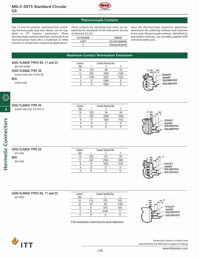
J-38www.ittcannon.com
Dimensions shown in inches (mm)Specifications and dimensions subject to change
J
Her
met
ic C
on
nec
tors
MIL-C-5015 Standard CircularGS
Thermocouple Contacts
Maximum Contact Termination Extensions
Size 12 and 16 contacts, machined from match-ing thermocouple lead wire alloys, can be sup-plied in ITT Cannon connectors. Thesethermocouple contacts maintain continuity fromthermal-sensor leads thru a bulkhead or otherclosures in temperature measuring applications.
These contacts for matching lead wires are de-tailed by the standards of the Instrument Societyof America (I.S.A.):
I.S.A Standards MaterialJ and Y Iron and constantan
K Chromel and alumel
Since the thermocouple connector applicationdetermines the soldering methods and materialsto be used, thermocouple contacts, identified bypermanent markings, are normally supplied withuntinned solder pots.
GS02 FLANGE TYPES 00, 11 and 25(pin and socket)
GS02 FLANGE TYPE 30(socket only) sizes 24 thru 48
BFH(socket only)
GS02 FLANGE TYPE 30(socket only) sizes 12s thru 22
GS02 FLANGE TYPE 30(pin only)
BFH(pin only)
GS06 FLANGE TYPES 00, 11 and 25(pin only)
Contact Contact Terminal No.Size 1 2 316 7/32 3/8 1/412 9/32 33/64 21/648 15/32 32/32 15/324 †† 63/64 ††0 †† 63/64 ††
Contact Contact Terminal No.Size 1 2 316 3/32 1/4 1/812 5/32 25/64 13/648 †† 19/32 11/324 †† †† ††0 †† †† ††
Contact Contact Terminal No.Size 1 2 316 3/32 1/4 1/812 5/32 25/64 13/648 †† 19/32 11/324 †† †† ††0 †† †† ††
Contact Contact Terminal No.Size 1 2 316 1/16 7/32 3/3212 1/8 3/8 11/648 †† 9/16 5/164 †† 61/64 ††0 †† †† ††
†† Not manufactured, contact factory for special requirements.
ca_J1-J50.qxd:Layout 1 2/10/11 8:52 AM Page 38

J-39www.ittcannon.com
Dimensions shown in inches (mm)Specifications and dimensions subject to change
J
Herm
etic Co
nn
ectors
MIL-C-5015 Standard CircularBFH / TBFH
The BFH is a hermetically sealed version of theBFR bulkhead fitting.
The TBFH-100 is a jam nut-mounted, thru-bulk-head receptacle for panel thicknesses of .187(4.75) thru .312 (7.92). Sealing against the bulk-head is accomplished by an O ring seal.
The TBFH-200 is similar to the TBFH-100 with alonger overall length for panel thicknesses of.375 (9.52) thru .750 (19.05).
The TBFH-110 is the hermetically sealed versionof the TBF thru-bulkhead receptacle. It is flangemounted and mates with 3106, 3107 and 3108plugs. Contacts are sealed to achieve hermeticitypreventing air leakage in excess of one microncubit foot per hour at a pressure differential ofone atmosphere. Receptacles with leak rate of.001 micron cubic foot per hour, and lower, arealso available.
Materials and Finishes
Contact and shells are steel. Standard finish isclear chromate over cadmium. Other finishes areavailable for high temperature and special appli-cations.
Materials and Finishes
TBFH 20 15 PS W 100BFH 14S 5 P W 100 2
SERIES PREFIXSHELL SIZECONTACT ARRANGEMENTCONTACT TYPEPOLARIZATIONSHELL STYLECONTACT TERMINALMODIFICATION CODE
SERIES PREFIXTBFH – Thru-bulkhead fitting, HermeticTBFH – Bulkhead fitting, Hermetic
SHELL SIZECoupling thread diameter figured in sixteenthsof an inch.
CONTACT ARRANGEMENTSee Pages J-31
CONTACT TYPEP — Pin (BFH)S — Socket (BFH)PS — Pin-Socket (sockets are on jam nut side)
(TBFH)PP — Pin-Pin (TBFH)SP — Socket-Pin (pins on jam nut side) (TBFH)
POLARIZATIONSee page J-34, for Alternate Insert Positions
SHELL SIZE00 – BFH (Thr’d digit contact termination)100 – TBFH (For up to 5/16 panel thickness)110 – Square flange200 – TBFH (For up to 3/4 panel thickness)
CONTACT TERMINAL (BFH only)1 – Eyelet2 – Solder pot3 – Short solder potB11 – Weldable
MODIFICATION CODEF208 – Stainless steel (304L type) hardware;
contacts .00005 min. gold over nickelConsult factory for other modification codes.
ca_J1-J50.qxd:Layout 1 2/10/11 8:52 AM Page 39

J-40www.ittcannon.com
Dimensions shown in inches (mm)Specifications and dimensions subject to change
J
Her
met
ic C
on
nec
tors
MIL-C-5015 Standard CircularBFH / TBFH
Bulkhead Receptacle
Part Numberby Shell Size* Pin Insert*•BFH8S-**P-00Δ•BFH10S-**P-00Δ•BFH10SL-**P-00Δ•BFH12S-**P-00Δ•BFH14S-**P-00Δ•BFH16S-**P-00Δ•BFH12-**P-00Δ•BFH14-**P-00Δ•BFH16-**P-00Δ•BFH18-**P-00Δ•BFH20-**P-00Δ•BFH22-**P-00Δ•BFH24-**P-00Δ•BFH28-**P-00Δ•BFH32-**P-00Δ•BFH36-**P-00Δ
O RingPart Number
MS28775-114MS28775-116MS28775-116MS28775-212MS28775-214MS28775-216MS28775-212MS28775-214MS28775-216MS28775-218MS28775-220MS28775-222MS28775-223MS28775-225MS28775-227MS28775-229
Pin1.062 (26.97)1.062 (26.97)1.062 (26.97)1.062 (26.97)1.062 (26.97)1.062 (26.97)1.500 (38.10)1.500 (38.10)1.500 (38.10)1.500 (38.10)1.500 (38.10)1.500 (38.10)1.500 (38.10)1.500 (38.10)1.500 (38.10)1.500 (38.10)
Socket———
1.094 (27.79)1.094 (27.79)1.094 (27.79)1.500 (38.10)1.500 (38.10)1.500 (38.10)1.500 (38.10)1.500 (38.10)1.500 (38.10)1.500 (38.10)1.500 (38.10)1.500 (38.10)1.500 (38.10)
N
.250 (6.35)
.250 (6.35)
.250 (6.35)
.281 (7.14)
.281 (7.14)
.281 (7.14)
.281 (7.14)
.281 (7.14)
.281 (7.14)
.281 (7.14)
.281 (7.14)
.281 (7.14)
.281 (7.14)
.281 (7.14)
.281 (7.14)
.281 (7.14)
P
.125 (3.18)
.125 (3.18)
.125 (3.18)
.125 (3.18)
.125 (3.18)
.141 (3.58)
.125 (3.18)
.125 (3.18)
.141 (3.58)
.141 (3.58)
.141 (3.58)
.141 (3.58)
.141 (3.58)
.141 (3.58)
.141 (3.58)
.151 (3.84)
R
1.062 (26.79)1.188 (30.18)1.188 (30.18)1.313 (33.35)1.438 (36.53)1.563 (39.70)1.313 (33.35)1.438 (36.53)1.563 (39.70)1.688 (42.88)1.813 (46.05)1.938 (49.23)2.062 (52.37)2.313 (58.75)2.563 (65.10)2.813 (71.45)
S
.813 (20.65)
.938 (28.83)
.938 (28.83)1.062 (26.79)1.188 (30.18)1.313 (33.35)1.062 (26.79)1.188 (30.18)1.313 (33.35)1.438 (36.53)1.563 (39.70)1.688 (42.88)1.875 (47.62)2.062 (52.37)2.313 (58.75)2.563 (65.10)
TMax.
.635 (16.13)
.760 (19.30)
.760 (19.30)
.885 (22.48)1.010 (25.65)1.135 (29.83).885 (22.48)
1.010 (25.65)1.135 (29.83)1.260 (32.00)1.385 (35.18)1.510 (38.35)1.635 (41.53)1.885 (47.88)2.260 (57.40)2.510 (63.75)
UMax.
.457 (11.61)
.575 (14.60)
.575 (14.60)
.689 (17.50)
.814 (20.68)
.939 (23.95)
.689 (17.50)
.814 (20.68)
.939 (23.85)1.057 (26.85)1.182 (30.02)1.307 (33.20)1.432 (36.37)1.682 (42.72)1.932 (49.07)2.174 (55.22)
VMax..277 (7.04).277 (7.04).277 (7.04).246 (6.25).246 (6.25).230 (5.84)
.422 (10.72)
.422 (10.72)
.422 (10.72)
.422 (10.72)
.422 (10.72)
.422 (10.72)
.422 (10.72)
.422 (10.72)
.422 (10.72)
.422 (10.72)
**For socket inserts, substitute S for P following the contact arrangement numbers.**Add contact arrangement number. See pages J-31 to J-32 for contact arrange-ments.• Available with pin inserts only.Δ Add contact terminal type. See Ordering Data, page J-38.
AThread
1/2-28UNEF-2A5/8-24NEF-2AE5/8-24NEF-2AE3/4-20UNEF-2A7/8-20UNEF-2A
1-3/4-20UNEF-2A3/4-20UNEF-2A7/8-20UNEF-2A
1-3/4-20UNEF-2A1-1/8-18UNEF-2A1-1/4-18UNEF-2A1-3/8-18UNEF-2A1-1/2-18UNEF-2A1-3/4-18UNS-2AE2-3/4-18UNS-2AE2-1/4-16UN-2AEE
L
BFH
ca_J1-J50.qxd:Layout 1 2/10/11 8:52 AM Page 40

J-41www.ittcannon.com
Dimensions shown in inches (mm)Specifications and dimensions subject to change
J
Herm
etic Co
nn
ectors
MIL-C-5015 Standard CircularBFH / TBFH
Part Numberby Shell Size* Pin Insert*TBFH12S-**PS-110TBFH14S-**PS-110TBFH16S-**PS-110TBFH12S-**PS-110TBFH14S-**PS-110TBFH16S-**PS-110TBFH18-**PS-110TBFH20-**PS-110TBFH22-**PS-110TBFH24-**PS-110TBFH28-**PS-110TBFH32-**PS-110TBFH36-**PS-110TBFH40-**PS-110TBFH44-**PS-110
CMax.
.729 (18.52)
.729 (18.52)
.729 (18.52)
.916 (23.27)
.916 (23.27)
.916 (23.27)
.916 (23.27)
.916 (23.27)
.916 (23.27)
.916 (23.27)
.916 (23.27)
.916 (23.27)
.916 (23.27)
.916 (23.27)
.916 (23.27)
DMin.
.450 (11.43)
.450 (11.43)
.450 (11.43)
.625 (15.88)
.625 (15.88)
.625 (15.88)
.625 (15.88)
.625 (15.88)
.625 (15.88)
.625 (15.88)
.625 (15.88)
.625 (15.88)
.625 (15.88)
.625 (15.88)
.625 (15.88)
E± .005 (0.13)
.120 (3.05)
.120 (3.05)
.120 (3.05)
.120 (3.05)
.120 (3.05)
.120 (3.05)
.120 (3.05)
.120 (3.05)
.120 (3.05)
.147 (3.73)
.147 (3.73)
.173 (4.39)
.173 (4.39)
.173 (4.39)
.173 (4.39)
GMax.
1.125 (28.58)1.219 (30.96)1.312 (33.32)1.125 (28.58)1.219 (30.96)1.406 (35.71)1.406 (35.71)1.531 (38.89)1.656 (42.06)1.781 (45.24)2.031 (51.59)2.281 (57.94)2.531 (64.29)2.781 (70.64)3.031 (76.99)
H± .005 (0.13) .812 (20.62).906 (23.01).968 (24.59).812 (20.62).906 (23.01)1.062 (26.97)1.062 (26.97)1.156 (29.36)1.250 (31.75)1.375 (34.92)1.562 (39.67)1.750 (44.45)1.937 (49.20)2.187 (55.55)2.375 (60.32)
KMax.
.281 (7.14)
.281 (7.14)
.281 (7.14)
.281 (7.14)
.281 (7.14)
.281 (7.14)
.281 (7.14)
.281 (7.14)
.281 (7.14)
.281 (7.14)
.281 (7.14).406 (10.31).406 (10.31).406 (10.31).406 (10.31)
LMax.
1.697 (43.10)1.697 (43.10)1.697 (43.10)2.072 (52.63)2.072 (52.63)2.072 (52.63)2.072 (52.63)2.072 (52.63)2.197 (55.80)2.197 (55.80)2.197 (55.80)2.197 (55.80)2.197 (55.80)2.197 (55.80)2.197 (55.80)
**Add contact arrangement number. See pages J-31 to J-32 for contact arrangements.NOTE: Available only with individual beads (steel web construction).
AThread
3/4-20UNEF-2A7/8-20UNEF-2A
1-3/4-20UNEF-2A3/4-20UNEF-2A7/8-20UNEF-2A
1-3/4-20UNEF-2A1-1/8-18UNEF-2A1-1/4-18UNEF-2A1-3/8-18UNEF-2A1-1/2-18UNEF-2A1-3/4-18UNEF-2A1-3/4-18UNEF-2A2-1/4-16UN-2AEE 2-1/2-16UN-2AEE 2-3/4-16UN-2AEE
TBFH-110
ca_J1-J50.qxd:Layout 1 2/10/11 8:52 AM Page 41

J-42www.ittcannon.com
Dimensions shown in inches (mm)Specifications and dimensions subject to change
J
Her
met
ic C
on
nec
tors
MIL-C-5015 Standard CircularBFH / TBFH
Part Numberby Shell SizeTBFH12S-**PS-†TBFH14S-**PS-†TBFH16S-**PS-†TBFH12-**PS-†TBFH14-**PS-†TBFH16-**PS-†TBFH18-**PS-†TBFH20-**PS-†TBFH22-**PS-†TBFH24-**PS-†TBFH28-**PS-†TBFH32-**PS-†TBFH36-**PS-†TBFH40-**PS-†TBFH44-**PS-†TBFH48-**PS-†
O RingPart Number
MS28775-114MS28775-116MS28775-116MS28775-212MS28775-214MS28775-216MS28775-212MS28775-214MS28775-216MS28775-218MS28775-220MS28775-222MS28775-223MS28775-225MS28775-227MS28775-229
CMax.
.635 (16.13)
.635 (16.13)
.635 (16.13)
.849 (21.56)
.849 (21.56)
.849 (21.56)
.849 (21.56)
.849 (21.56)
.849 (21.56)
.849 (21.56)
.849 (21.56)
.849 (21.56)
.849 (21.56)
.849 (21.56)
.849 (21.56)
.849 (21.56)
EMin.
.450 (11.43)
.450 (11.43)
.450 (11.43)
.625 (15.88)
.625 (15.88)
.625 (15.88)
.625 (15.88)
.625 (15.88)
.625 (15.88)
.625 (15.88)
.625 (15.88)
.625 (15.88)
.625 (15.88)
.625 (15.88)
.625 (15.88)
.625 (15.88)
FMax.
1.322 (33.58)1.447 (36.75)1.572 (39.93)1.322 (33.58)1.447 (36.75)1.572 (39.93)1.697 (43.10)1.822 (46.28)1.947 (49.45)2.072 (52.63)2.322 (58.98)2.572 (65.33)2.822 (71.68)3.227 (81.97)3.460 (97.88)3.760 (95.50)
GMax.
.844 (21.44)
.969 (21.62)1.094 (27.79).844 (21.44).969 (21.62)1.094 (27.79)1.219 (30.96)1.344 (34.14)1.469 (37.31)1.594 (40.49)1.840 (46.74)2.090 (53.09)2.340 (59.44)2.685 (68.20)2.842 (72.19)3.188 (80.98)
JMax.
.855 (21.72)1.010 (25.63)1.135 (28.83).885 (22.48)
1.010 (25.65)1.135 (28.83)1.260 (32.00)1.385 (35.18)1.510 (38.35)1.635 (41.53)1.885 (47.88)2.260 (57.40)2.510 (63.75)2.760 (70.10)3.010 (76.45)3.510 (89.15)
KMax.
1.072 (27.23)1.197 (30.40)1.322 (33.58)1.072 (27.23)1.197 (30.40)1.322 (33.58)1.447 (36.75)1.572 (39.93)1.697 (43.10)1.885 (47.88)2.072 (52.63)2.322 (58.98)2.572 (65.33)2.885 (73.28)3.085 (78.36)3.385 (85.98)
LMax.
.689 (17.50)
.814 (20.68)
.939 (23.85)
.689 (17.50)
.814 (23.85)
.939 (23.85)1.057 (26.85)1.182 (36.75)1.307 (33.20)1.432 (36.37)1.682 (42.72)1.932 (49.07)2.174 (55.22)2.423 (61.54)2.673 (67.89)2.923 (74.24 )
MMax.
.250 (6.35)
.250 (6.35)
.250 (6.35)
.187 (4.75)
.187 (4.75)
.187 (4.75)
.187 (4.75)
.187 (4.75)
.187 (4.75)
.312 (7.92)
.312 (7.92)
.312 (7.92)
.312 (7.92)
.312 (7.92)
.312 (7.92)
.312 (7.92)
NMax.
1.825 (46.36)1.825 (46.36)1.825 (46.36)2.200 (55.88)2.200 (55.88)2.200 (55.88)2.200 (55.88)2.200 (55.88)2.200 (55.88)2.325 (59.06)2.325 (59.06)2.325 (59.06)2.325 (59.06)2.325 (59.06)2.325 (59.06)2.325 (59.06)
MMax.
.375 (9.52)
.375 (9.52)
.375 (9.52).750 (19.05).750 (19.05).750 (19.05).750 (19.05).750 (19.05).750 (19.05).750 (19.05).750 (19.05).750 (19.05).750 (19.05).750 (19.05).750 (19.05).750 (19.05)
NMax.
2.015 (51.18)2.015 (51.18)2.015 (51.18)2.859 (72.62)2.859 (72.62)2.859 (72.62)2.859 (72.62)2.859 (72.62)2.859 (72.62)2.859 (72.62)2.859 (72.62)2.859 (72.62)2.859 (72.62)2.859 (72.62)2.859 (72.62)2.859 (72.62)
**Add contact arrangement number. See pages J-31 to J-32 for contact arrangements.†Add panel accommodation number; 100 or 200.NOTE: Available only with individual beads (steel web construction). Same mounting
hole dimensions as BFH.
AThread
3/4-20UNEF-2A7/8-20UNEF-2A
1-3/4-20UNEF-2A3/4-20UNEF-2A7/8-20UNEF-2A
1-3/4-20UNEF-2A1-1/8-18UNEF-2A1-1/4-18UNEF-2A1-3/8-18UNEF-2A1-1/2-18UNEF-2A1-3/4-18UNS-2AE2-3/4-18UNS-2AE2-1/4-16UN-2AEE 2-1/2-16UN-2AEE 2-3/4-16UN-2AEE3-3/4-16UN-2AEE
TBFH-100 TBFH-200
Thru-Bulkhead Receptacle
Mounting Dimensions — BFH and TBFH-100/-200
For Shell Sizes8S
10S, 10SL12S, 1214S, 1416S, 16
18202224283236404448
D+ .015 (0.38)- .000 (0.00)1.460 (11.68)1.578 (14.68)1.692 (17.58)1.817 (20.75)1.942 (23.93)1.060 (26.92)1.185 (30.10)1.310 (33.27)1.435 (36.45)1.687 (42.85)1.937 (49.20)2.177 (55.30)2.426 (61.62)2.676 (67.97)2.926 (74.32)
E+ .015 (0.38)- .000 (0.00)1.500 (12.70)1.625 (15.88)1.750 (19.05)1.875 (22.22)1.000 (25.40)1.125 (28.58)1.250 (31.75)1.375 (34.92)1.500 (38.10)1.750 (44.45)2.000 (50.80)2.250 (57.15)2.500 (63.50)2.750 (69.85)3.000 (76.20)
TBFH-100 / -200Jam Nut Mounted
ca_J1-J50.qxd:Layout 1 2/10/11 8:52 AM Page 42

J-43www.ittcannon.com
Dimensions shown in inches (mm)Specifications and dimensions subject to change
J
Herm
etic Co
nn
ectors
MIL-C-83513 MicrominiatureMDMH
• Lightweight, rugged microminiature connectors• Contacts on .050 (1.27) centers, providing sig-
nificant space and weight savings.• Field proven, reliable twist pin contacts offer
high mechanical and electrical integrity overhundreds of mating and unmating cycles.
MDMH microminiature hermetic connectors arecompression glass sealed through a steel shell andinto a diallyl phthalate “front end” insulator. An interfacial seal provides environmental protection when mated. MDMH receptacles are soldered to a chassis or container providing acompletely leak-proof unit.
How to Order
MDMH - 51 S S
SERIES
CONTACT LAYOUT
CONTACTS
TERMINATION TYPE
SERIES: Hermetic Micro D Receptacle
CONTACT LAYOUT:9, 15, 21, 25, 31, 37, 51, 100
CONTACTS:Socket (only)
TERMINATION TYPE:Solder pot to accept #26 AWGmax. harness wire
Note: Mating Micro D Plugs are the MDM Series.To order call:ITT CannonSanta Ana, California714-557-4700
Standard Data
MATERIALS AND FINISHESShell Mild steel, fused tinInsulator Glass-filled diallyl phthalate per MIL-M-14. Type SDGFContacts Copper Alloy, gold plated sockets on mild steel gold/nickel plated pinsContact Termination Solder potsHermetic Seal Compression glassLeak Rate 1 micron cubic ft./hr. max (1.04 x 10⁻⁵ cc/sec at 1 ATM pressure differential)
ELECTRICALNo. of Contacts 9 thru 100Dialectric Withstanding Voltage 150 VACInsulation Resistance 5,000 Meg. Ohms Min.Wire Size #26 thru #30 AWGContact Termination Solder pot
ELECTRICALSize or Length 8 sizesService Class Hermetically sealedCoupling Friction/jacksPolarization Keystone-shaped shellsContact Spacing .050 (1.27) centersShell Style Receptacle, solder mounted
ca_J1-J50.qxd:Layout 1 2/10/11 8:52 AM Page 43

J-44www.ittcannon.com
Dimensions shown in inches (mm)Specifications and dimensions subject to change
J
Her
met
ic C
on
nec
tors
MIL-C-83513 MicrominiatureMDMH
Contact Arrangements
Shell Dimensions
Part Numberby Shell SizeMDMH-9SMDMH-15SMDMH-21SMDMH-25SMDMH-31SMDMH-37SMDMH-51SMDMH-100S
AMax.
.885 (22.48)1.035 (26.29)1.185 (30.10)1.285 (32.64)1.435 (36.45)1.585 (40.26)1.535 (38.99)2.275 (57.78)
BMin.
.738 (18.74)
.888 (22.55)1.038 (26.36)1.137 (28.87)1.288 (32.72)1.438 (36.53)1.388 (35.26)2.078 (52.78)
CMax.
.400 (10.16)
.550 (13.97)
.770 (17.78)
.800 (20.32)
.950 (24.13)1.100 (27.94)1.050 (26.67)1.455 (36.97)
DMax.
.270 (6.86)
.270 (6.86)
.270 (6.86)
.270 (6.86)
.270 (6.86)
.270 (6.86)
.315 (8.00)
.365 (9.27)
EMax.
.430 (10.92)
.430 (10.92)
.430 (10.92)
.430 (10.92)
.430 (10.92)
.430 (10.92)
.473 (12.01)
.522 (13.26)
F± .005 (0.13).565 (14.35).715 (18.16).865 (21.97).965 (24.51)1.115 (28.32)1.265 (32.13)1.215 (30.86)1.800 (45.72)
GMax.
.261 (6.63)
.261 (6.63)
.261 (6.63)
.261 (6.63)
.261 (6.63)
.261 (6.63)
.315 (8.00).410 (10.41)
Face view of socket insert — use reverse order for wiring side.
Contact indentification numbers are for reference only and do not appear on insulator or connector body.
ca_J1-J50.qxd:Layout 1 2/10/11 8:52 AM Page 44

J-45www.ittcannon.com
Dimensions shown in inches (mm)Specifications and dimensions subject to change
J
Herm
etic Co
nn
ectors
MIL-C-24308 D SubminiatureD*H
D*H hermetically sealed connectors are designedto meet environmental conditions of extremepressure differential. These connectors are partof the ITT Cannon D Subminiature series and arequalified to MIL-C-24308 (refer to page 41 forcross reference information). The hermetic sealprevents leakage and subsequent accumulationof corrosive moisture behind the connector.There are five basic shell sizes in both standardand thru-bulkhead designs which can accommo-date from nine to 50 contacts. Polarization isachieved by the keystone shape of the shell, afeature of all connectors within the D Subminia-
ture series.
How to Order
D E H 9 P 0 0 1
SERIES PREFIXSHELL SIZECLASSCONTACT ARRANGEMENTCONTACT TYPEFLANGE TYPEMOUNTINGCONTACT TERMINATION
D*H
SERIES PREFIXITT Cannon prefix
SHELL SIZEE, A, B, C, D
CLASSH — Hermetic
CONTACT ARRANGEMENTSee page 41.
CONTACT TYPEP — Pin only
FLANGE TYPE0 — Solid flange, no mounting or locking
facilities1 — Two .120 dia. mounting holes2 — Two jackposts accepting
No. 4-40 screws
MOUNTING0 — Standard4 — Shell brazed to plate; can be front or
rear panel mounted
CONTACT TERMINATION1 — Eyelet2 — Solder pot
Printed circuit contacts — Consult factory
D E TB H 9 P 0
SERIES PREFIXSHELL SIZESHELL STYLECLASSCONTACT ARRANGEMENTCONTACT TYPEFLANGE TYPE
D*TBH
SERIES PREFIXITT Cannon prefix
SHELL SIZEE, A, B, C, D
SHELL STYLETB – Thru-bulkhead
CLASSH — Hermetic
CONTACT ARRANGEMENTSee page J-48.
CONTACT TYPEP — Pin only
FLANGE TYPE00 — Solid flange, no mounting or locking
facilities10 — Two .120 (3.05) dia. mounting holes20 — Two jackposts accepting #4-40 screws
on layout identification side30 — Two jackposts on both sides
(D*TBH only)
ca_J1-J50.qxd:Layout 1 2/10/11 8:52 AM Page 45

J-46www.ittcannon.com
Dimensions shown in inches (mm)Specifications and dimensions subject to change
J
Her
met
ic C
on
nec
tors
MIL-C-24308 D SubminiatureD*H
Materials and Finishes
Shell — In accordance with ASTM 620, 619, 568 — Low carbon steel, plated with electro-deposited tinover cadmium over copper flash
Insulator — Compression glassContacts — In accordance with ASTM A108 — Steel, plated with gold over nickel
Military vs. ITT Cannon Current Ratings
The ITT Cannon rating for #20 contacts is 5amps, which means 5 amps for all contacts simul-taneously. MIL-W-5088 rates #20 contacts at 7.5amps maximum. The explanation is as follows:
MIL-W-5088B, Paragraph 3.9.2.1.2 specifies:“Table 1 current ratings for cables in bundles arebased upon 15 or more cables carrying no morethan 20% of the total carrying capacity of thebundle.”
Table 1 specifies a current rating of 7.5 ampsmaximum for single wires in bundles of 15 ormore wires. NOTE: Wires and contacts are bothconsidered to be in the category of conductors.
ExplanationIf 15 wires (normally rated at 7.5 amps per wiremaximum, or at least a total bundle current of112.5 amps) are not to carry more than 20% ofthe total 112.5 amps, the average current ratingper wire is 20% of 112.5 amps (total bundle ca-pacity) divided by 15 (number of wires).
ConclusionThe Military rating of #20 contacts or wires is 1.5amps average (based on 15 wires per bundle or15 contacts per plug) vs an ITT Cannon rating of5 amps.
Average Maximum Temperature vs Connector Sizefor various current ratings of mated pairs of DSubminiature connectors
Notes:1. Free air condition. Connectors not shielded from ambient
condition in any manner.2. Confined condition. Connectors placed in insulated box (1 x 2
x 3.5) during test, with no moving air.3. Average maximum temperature stabilization: 1 hour or less in
all cases.4. All contacts in each mated pair tested were wired in series with
specified current flowing.5. Ambient conditions 77°F, 50% rh.
Test Data
All voltages are measured from contact to shell,in unmated condition.
Voltage Rating (ac) Altitude (feet)Sea Level 20,000 50,000 70,000
Test (Max.) 750 625 225 175
Insulation Resistance.....5,000 megohms min. when testedper MIL-STD-202A, Method 302
Contact Voltage Drop ....6.67 millivolts per amp max. whenmated with any Original D orGOLDEN-D connector receptacle
Air Leakage Rate ...........1 micron cubic ft/hour max. (1.04 x10⁻⁵ cc/sec.) at 1 atm pressure differential
Vibration Resistance ......Exceeds test requirements of MIL-Ref. MIL-C-24308 STD-202, Method 204, Condition B
Corrosion Resistance .....Exceeds requirements of 48 hourRef. MIL-C-24308 salt spray exposure, tested in
accordance with MIL-STD-202,Method 101
Shock ............................Exceeds tests for MIL-STD-202Ref. MIL-C-24308 Method 213
DWV..............................750 VAC rms
7.5 AMP CONFINED
7.5 AMP FREE AIR
5 AMP CONFINED
5 AMP FREE AIR
TEM
PERA
TURE
(F°)
CONNECTOR SIZEAE B C D
300
250
200
150
100
150
ca_J1-J50.qxd:Layout 1 2/10/11 8:52 AM Page 46
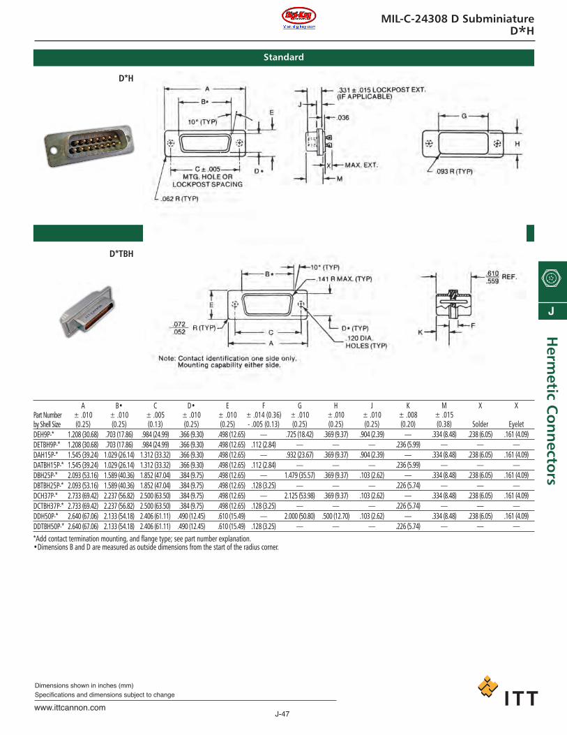
J-47www.ittcannon.com
Dimensions shown in inches (mm)Specifications and dimensions subject to change
J
Herm
etic Co
nn
ectors
MIL-C-24308 D SubminiatureD*H
D*H
Standard
Through Bulkhead
Part Numberby Shell SizeDEH9P-*DETBH9P-*DAH15P-*DATBH15P-*DBH25P-*DBTBH25P-*DCH37P-*DCTBH37P-*DDH50P-*DDTBH50P-*
A± .010(0.25)
1.208 (30.68)1.208 (30.68)1.545 (39.24)1.545 (39.24)2.093 (53.16)2.093 (53.16)2.733 (69.42)2.733 (69.42)2.640 (67.06)2.640 (67.06)
B•± .010(0.25)
.703 (17.86)
.703 (17.86)1.029 (26.14)1.029 (26.14)1.589 (40.36)1.589 (40.36)2.237 (56.82)2.237 (56.82)2.133 (54.18)2.133 (54.18)
C± .005(0.13)
.984 (24.99)
.984 (24.99)1.312 (33.32)1.312 (33.32)1.852 (47.04)1.852 (47.04)2.500 (63.50)2.500 (63.50)2.406 (61.11)2.406 (61.11)
D•± .010(0.25)
.366 (9.30)
.366 (9.30)
.366 (9.30)
.366 (9.30)
.384 (9.75)
.384 (9.75)
.384 (9.75)
.384 (9.75).490 (12.45).490 (12.45)
E ± .010(0.25)
.498 (12.65)
.498 (12.65)
.498 (12.65)
.498 (12.65)
.498 (12.65)
.498 (12.65)
.498 (12.65)
.498 (12.65)
.610 (15.49)
.610 (15.49)
F ± .014 (0.36)- .005 (0.13)
—.112 (2.84)
—.112 (2.84)
—.128 (3.25)
—.128 (3.25)
—.128 (3.25)
G ± .010(0.25)
.725 (18.42)—
.932 (23.67)—
1.479 (35.57)—
2.125 (53.98)—
2.000 (50.80)—
H± .010(0.25)
.369 (9.37)—
.369 (9.37)—
.369 (9.37)—
.369 (9.37)—
.500 (12.70)—
J± .010(0.25)
.904 (2.39)—
.904 (2.39)—
.103 (2.62)—
.103 (2.62)—
.103 (2.62)—
K± .008(0.20)
—.236 (5.99)
—.236 (5.99)
—.226 (5.74)
—.226 (5.74)
—.226 (5.74)
M± .015(0.38)
.334 (8.48)—
.334 (8.48)—
.334 (8.48)—
.334 (8.48)—
.334 (8.48)—
X
Solder.238 (6.05)
—.238 (6.05)
—.238 (6.05)
—.238 (6.05)
—.238 (6.05)
—
X
Eyelet.161 (4.09)
—.161 (4.09)
—.161 (4.09)
—.161 (4.09)
—.161 (4.09)
—*Add contact termination mounting, and flange type; see part number explanation.•Dimensions B and D are measured as outside dimensions from the start of the radius corner.
D*TBH
ca_J1-J50.qxd:Layout 1 2/10/11 8:52 AM Page 47
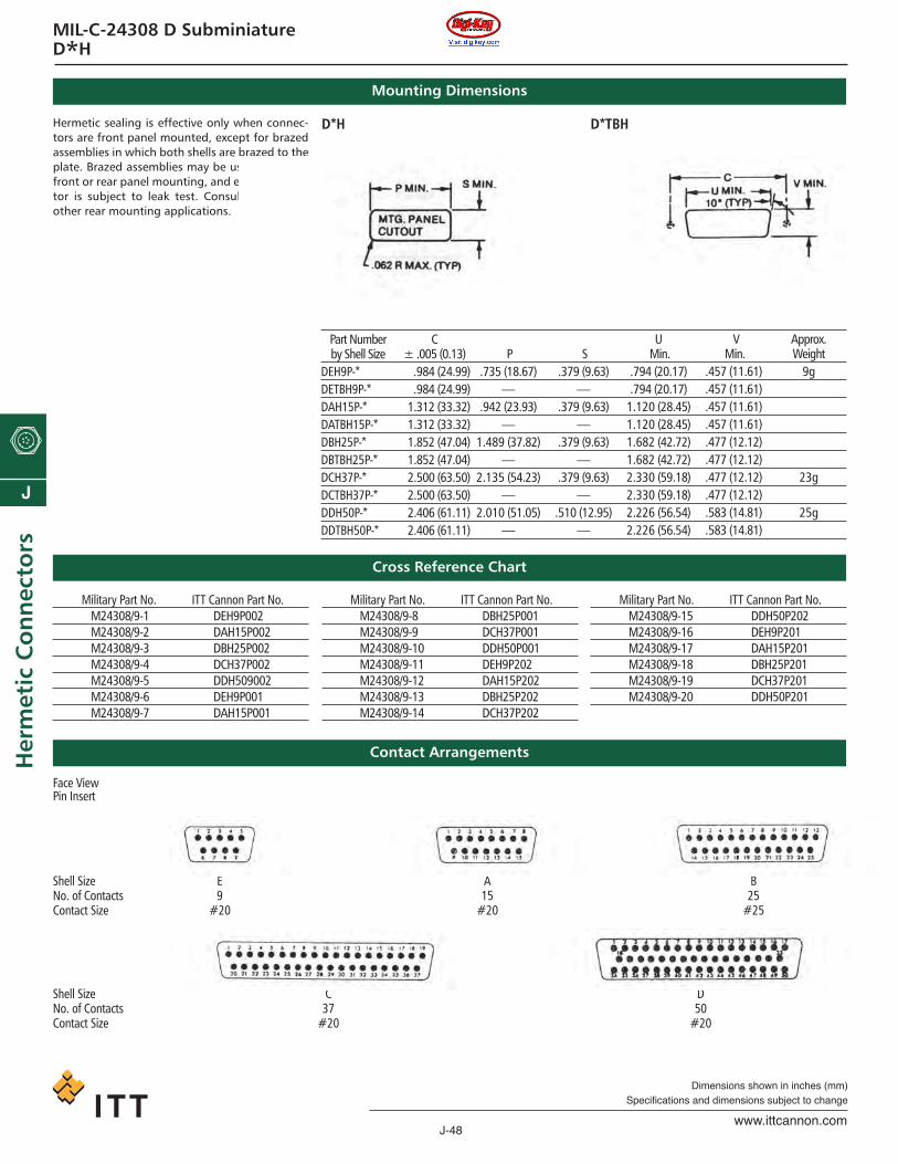
J-48www.ittcannon.com
Dimensions shown in inches (mm)Specifications and dimensions subject to change
J
Her
met
ic C
on
nec
tors
MIL-C-24308 D SubminiatureD*H
Hermetic sealing is effective only when connec-tors are front panel mounted, except for brazedassemblies in which both shells are brazed to theplate. Brazed assemblies may be used for eitherfront or rear panel mounting, and entire connec-tor is subject to leak test. Consult factory forother rear mounting applications.
Mounting Dimensions
Cross Reference Chart
D*H D*TBH
Part Numberby Shell Size
DEH9P-*DETBH9P-*DAH15P-*DATBH15P-*DBH25P-*DBTBH25P-*DCH37P-*DCTBH37P-*DDH50P-*DDTBH50P-*
C± .005 (0.13)
.984 (24.99)
.984 (24.99)1.312 (33.32)1.312 (33.32)1.852 (47.04)1.852 (47.04)2.500 (63.50)2.500 (63.50)2.406 (61.11)2.406 (61.11)
P.735 (18.67)
—.942 (23.93)
—1.489 (37.82)
—2.135 (54.23)
—2.010 (51.05)
—
S.379 (9.63)
—.379 (9.63)
—.379 (9.63)
—.379 (9.63)
—.510 (12.95)
—
U Min.
.794 (20.17)
.794 (20.17)1.120 (28.45)1.120 (28.45)1.682 (42.72)1.682 (42.72)2.330 (59.18)2.330 (59.18)2.226 (56.54)2.226 (56.54)
VMin.
.457 (11.61)
.457 (11.61)
.457 (11.61)
.457 (11.61)
.477 (12.12)
.477 (12.12)
.477 (12.12)
.477 (12.12)
.583 (14.81)
.583 (14.81)
Approx. Weight
9g
23g
25g
Contact Arrangements
Military Part No. ITT Cannon Part No.M24308/9-1 DEH9P002M24308/9-2 DAH15P002M24308/9-3 DBH25P002M24308/9-4 DCH37P002M24308/9-5 DDH509002M24308/9-6 DEH9P001M24308/9-7 DAH15P001
Military Part No. ITT Cannon Part No.M24308/9-8 DBH25P001M24308/9-9 DCH37P001M24308/9-10 DDH50P001M24308/9-11 DEH9P202M24308/9-12 DAH15P202M24308/9-13 DBH25P202M24308/9-14 DCH37P202
Military Part No. ITT Cannon Part No.M24308/9-15 DDH50P202M24308/9-16 DEH9P201M24308/9-17 DAH15P201M24308/9-18 DBH25P201M24308/9-19 DCH37P201M24308/9-20 DDH50P201
Face ViewPin Insert
Shell Size E A BNo. of Contacts 9 15 25Contact Size #20 #20 #25
Shell Size C DNo. of Contacts 37 50Contact Size #20 #20
ca_J1-J50.qxd:Layout 1 2/10/11 8:52 AM Page 48

J
When off-the-shelf won’t do…… turn to ITT for custom-engineered
interconnect solutions
Unmatched design, development, experience- for nearly 90 years
Whether it’s land, sea, air, or space – ITT experience and innovation helps providecustomers with high-performance, high-reliability, high-quality interconnect solu-tions. Specializing in harsh environment and mission-critical applications, ITT cus-tom products are specified on major Aerospace and Hydrospace programsincluding:
• Patriot missile• Tomahawk missile • Trident missile• Trident submarine• Sidewinder missile• Harpoon missile• CVN-78 aircraft carrier• Mark 48 torpedo• Vertical Launch System• Delta Rocket systems • Titan Launch Vehicle• Apache Helicopter• International Space Station • Space Shuttle
AerospaceITT is the worldwide leader in the development of special separationconnector systems required by today's high performance missile androcket vehicles:
• Custom umbilical interconnect systems and cablingfor system launch applications
• Special connectors for rocket interstage separation• Lanyard and ring lock connectors for pylon and
weapons stores jettison• Spring loaded connectors where blind mating is required• Connectors designed to couple and uncouple in a
Zero-G space environment.
HydrospaceFor more than 40 years, ITT has been designing special bulkhead con-nector headers and interconnect systems for harsh undersea applica-tions including:
• High pressure hull and missile tube penetrators• Wet mateable connectors and custom headers for
submarine sonar arrays• Umbilical cable assemblies for torpedo tube-launched
missiles systems• Custom interface connectors for ship launch applications
ca_J1-J50.qxd:Layout 1 2/10/11 8:52 AM Page 49

J
Your Space and Special interconnectneeds are covered
When a mil-spec product just won’t do, count on ITT todevelop the right special-purpose connector or cableharness for your military or commercial, aerospace, andhydrospace applications. From special-release connec-tors found in missile and launch vehicles to special high-pressure bulkhead connectors found in submarine- andship-based systems, ITT will meet your special connectorneeds. From blind mating applications to special cou-pling requirements, our custom designs are backed byour comprehensive capability to test and certify to DODand customer specifications.
Special release connectorsThe supplier of choice for major launch vehicles andweapons systems programs, ITT’s family of special releaseconnectors feature special umbilical and lanyard releasefunctions that automatically disconnect at the time of sys-tem launch. Ideal for interstage separation, weapons
store, and pylon applications, these connectorscan incorporate both pneumatic and electrical
lines in the same assembly.
Special bulkhead and hull penetrating connectorsITT’s wide range of special ship and SUB-SAFE bulkhead connectors pro-vide the critical electrical interface required to penetrate and carry signalsthrough the hull or bulkhead of military ships or submarine vehicles. Ourheader assemblies utilize compression glass sealing to stainless steel shells. Thisinnovative assembly provides a very strong and highly reliable hermetic seal thatwill operate at extreme temperatures and pressures up to 20,000 P.S.I.
Custom connectors and cable assemblies.Customized service.
ITT continues to be the first choice for the design and development of uniqueand customer specific applications. Our representatives will work with
your engineering team to develop a set of solutions that meet yourperformance, schedule, and cost requirements. With rapid prototypeservice from our comprehensive model shop, and DVT qualification test-ing from our complete in house PEL (Product Eval-uation Lab), ITT will deliver your custom solutionon time from concept to production.
RoHS and DFARS CompliantITT remains committed to supporting our customers with full compli-
ance to the DFARS directives relating to specialty metals. Further, ITT con-tinues to develop RoHS compliant products that are lead-free. As
appropriate, we will continue to offer leaded product for those applicationsrequiring it. For more information on ITT’s RoHS
initiative, visit www.ittcannon.com/RoHS.
ca_J1-J50.qxd:Layout 1 2/10/11 8:52 AM Page 50