gilmour, adam (2016) improving the assessment and outcome
TRANSCRIPT

Glasgow Theses Service http://theses.gla.ac.uk/
Gilmour, Adam (2016) Improving the assessment and outcome of free tissue transfer breast reconstruction. MD thesis. http://theses.gla.ac.uk/7458/ Copyright and moral rights for this thesis are retained by the author A copy can be downloaded for personal non-commercial research or study This thesis cannot be reproduced or quoted extensively from without first obtaining permission in writing from the Author The content must not be changed in any way or sold commercially in any format or medium without the formal permission of the Author When referring to this work, full bibliographic details including the author, title, awarding institution and date of the thesis must be given

Improving the assessment
and outcome of free tissue
transfer breast
reconstruction
Adam Gilmour MBChB – University of Glasgow
MRCS – Royal College of Surgeons of Edinburgh
This being a thesis submitted in fulfilment of the
requirements for the Degree of Doctorate of Medicine (MD)
Faculty of Medicine
College of Medical, Veterinary and Life Sciences
University of Glasgow
October 2015
© A Gilmour 2015

2
Abstract
Introduction: Free tissue transfer using an abdominal tissue flap is a commonly used
method of breast reconstruction. However, there are well recognised complications
including venous congestion, fat necrosis and flap loss associated with the perfusion of
these flaps. Post-operative aesthetic outcome assessment of such breast reconstructions
have also proven to be difficult with current methods displaying poor inter-rater reliability
and patient correlation. The aim of this research was to investigate potential improvements
to the post-operative outcome of free abdominal tissue transfer breast reconstruction by
assessing the effects of vascular augmentation interventions on flap perfusion and to assess
the use of real-time digital video as a post-operative assessment tool.
Methods: An in-vivo pilot study carried out on 12 patients undergoing DIEP flap breast
reconstruction assessed the effect on Zone IV perfusion, using LDI and ICG angiography,
of vascular augmentation of the flap using the contralateral SIEA and SIEV. A further
animal experimental study was carried out on 12 Sprague Dawley rats to assess the effects
on main pedicle arterial blood flow and on Zone I and Zone IV perfusion of vascular
augmentation of the abdominal flap using the contralateral vascular system. A separate
post-operative assessment study was undertaken on 35 breast reconstruction patients who
evaluated their own reconstructions via patient questionnaire and underwent photograph
and real-time digital video capture of their reconstructions with subsequent panel
assessment.
Results: Our results showed that combined vascular augmentation of DIEP flaps, using
both the SIEA and SIEV together, led to an increase in Zone IV perfusion. Vascular
augmentation of the rat abdominal flaps also led to a significant increase in Zone I/IV
perfusion, but the augmentation procedure resulted in a decreased main pedicle arterial
blood flow. Our post-operative assessment study revealed that real-time digital video
footage led to greater inter-rater agreement with regards to cosmesis and shape than
photography and also correlated more with patient self-assessment.
Conclusion: Vascular augmentation of abdominal free tissue flaps using the contralateral
vascular system results in an increase to Zone IV perfusion, however this may lead to
decreased main pedicle arterial blood flow. Real-time digital video is a valid post-operative
aesthetic assessment method of breast reconstruction outcome and is superior to static
photography when coupled with panel assessment.

3
Table of Contents
Abstract .................................................................................................................................. 2
List of Tables.......................................................................................................................... 7
List of Figures ........................................................................................................................ 8
Acknowledgement................................................................................................................ 10
Author’s Declaration ............................................................................................................ 11
Definitions/Abbreviations .................................................................................................... 12
Awards, Presentations & Publications arising from work contributing to Thesis ............... 13
Chapter 1: Introduction ....................................................................................................... 14
1.1 Microvascular surgery and Free Tissue Transfer .................................................. 14
1.2 Skin and Fat Blood Supply .................................................................................... 15
1.2.1 Cutaneous Territories, Angiosomes and Venosomes..................................... 16
1.2.2 Perforasomes .................................................................................................. 20
1.2.3 Perforator flap perfusion physiology ............................................................. 22
1.3 Breast Reconstruction ............................................................................................ 24
1.3.1 Choice of Reconstruction ............................................................................... 24
1.4 Free Autologous Tissue Breast Reconstruction .................................................... 25
1.5 Abdominal Blood Supply ...................................................................................... 26
1.6 Abdominal Tissue Transfer in Breast Reconstruction........................................... 30
1.6.1 TRAM Flap .................................................................................................... 30
1.6.2 DIEP Flap ....................................................................................................... 32
1.6.3 SIEA Flap ....................................................................................................... 34
1.6.4 Lower abdominal “zones” .............................................................................. 35
1.6.5 Vascular related complications associated with DIEP flaps .......................... 38
1.6.6 Vascular augmentation of DIEP flaps ............................................................ 41
1.7 Assessment of DIEP flap flow/perfusion .............................................................. 45
1.7.1 Laser Doppler Flowmetry .............................................................................. 45
1.7.2 Indocyanine Green Angiography ................................................................... 48
1.7.3 Intravascular flow measurement using ultrasonic transit-time flow meter .... 50
1.8 Volume/skin requirements in DIEP flap transfer and associated problems with
Zone IV ............................................................................................................................ 51
1.8.1 Pro-active vascular augmentation of DIEP flaps ........................................... 52
1.9 Potential concerns of vascular augmentation of abdominal flaps ......................... 54
1.10 Outcomes of DIEP flap breast reconstruction ................................................... 55
1.10.1 Patient Reported Outcome Measures ............................................................. 55
1.10.2 Aesthetic Outcome ......................................................................................... 57
1.10.3 Problems associated with outcome assessment.............................................. 58
1.10.4 Conventional subjective methods of aesthetic assessment ............................ 59

4
1.10.5 Novel objective methods of aesthetic assessment .......................................... 60
1.11 Summary ............................................................................................................ 60
Chapter 2: Outline of Completed Studies ........................................................................... 62
2.1 The effect of vascular augmentation on DIEP flap Zone IV perfusion utilising the
contralateral SIEA/SIEV .................................................................................................. 62
2.2 The effects of vascular augmentation on abdominal flap Zone I / IV perfusion and
main pedicle arterial blood flow in an experimental animal model ................................. 62
2.3 The use of real-time digital video in the assessment of post-operative outcomes of
breast reconstruction ........................................................................................................ 62
Chapter 3: Materials and Methods ...................................................................................... 63
3.1 Materials and Methods for Chapter 4 .................................................................... 63
3.1.1 Ethical Approval ............................................................................................ 63
3.1.2 Statistical Design ............................................................................................ 63
3.1.3 Patient Selection ............................................................................................. 63
3.1.4 Clinical assessment ........................................................................................ 64
3.1.5 Randomisation Process .................................................................................. 64
3.1.6 Environmental Conditions ............................................................................. 65
3.1.7 Laser Doppler Imaging .................................................................................. 65
3.1.8 ICG Angiography ........................................................................................... 67
3.1.9 Operative Procedure and Measurement Process ............................................ 70
3.1.10 LDI Scan Analysis ......................................................................................... 74
3.1.11 ICG Scan Analysis ......................................................................................... 75
3.1.12 Statistical Analysis ......................................................................................... 75
3.2 Materials and Methods for Chapter 5 .................................................................... 77
3.2.1 Ethical Approval ............................................................................................ 77
3.2.2 Statistical Design ............................................................................................ 77
3.2.3 Animals .......................................................................................................... 78
3.2.4 Anaesthesia and Peri-operative care .............................................................. 78
3.2.5 Randomisation Process .................................................................................. 79
3.2.6 Environmental Conditions ............................................................................. 79
3.2.7 Laser Doppler Flowmetry .............................................................................. 79
3.2.8 Microvascular Flow Measurement ................................................................. 80
3.2.9 Experimental Procedure ................................................................................. 83
3.2.10 Laser Doppler Flowmetry Analysis ............................................................... 89
3.2.11 Intravascular Flow / Temperature Analysis ................................................... 89
3.2.12 Statistical Analysis ......................................................................................... 89
3.3 Materials and Methods for Chapter 6 .................................................................... 91
3.3.1 Ethical Approval ............................................................................................ 91
3.3.2 Statistical Design ............................................................................................ 91
3.3.3 Patient Selection ............................................................................................. 92

5
3.3.4 Clinical assessment ........................................................................................ 92
3.3.5 Patient Satisfaction Assessment ..................................................................... 93
3.3.6 Standard photography .................................................................................... 93
3.3.7 Video capture ................................................................................................. 93
3.3.8 Creation of image/video sets .......................................................................... 95
3.3.9 Panel Assessment Process .............................................................................. 96
3.3.10 Statistical Analysis ......................................................................................... 97
Chapter 4: The effect of vascular augmentation on DIEP flap Zone IV perfusion utilising
the contralateral SIEA/SIEV ................................................................................................ 99
4.1 Introduction ........................................................................................................... 99
4.2 Methods ................................................................................................................. 99
4.3 Results ................................................................................................................... 99
4.3.1 Patients ........................................................................................................... 99
4.3.2 Intra-operative Details .................................................................................. 103
4.3.3 Zone IV Skin Perfusion assessed using LDI ................................................ 104
4.3.4 Zone IV skin perfusion assessed using ICG Angiography .......................... 107
4.3.5 Zone IV fat perfusion assessed using ICG Angiography ............................. 110
4.3.6 Effect of Perforator Row .............................................................................. 111
4.3.7 Effect of Perforator Number ........................................................................ 112
4.3.8 Sub-analysis excluding Patient 6 ................................................................. 112
4.3.9 Sub-analysis excluding Patients 9 and 10 .................................................... 112
4.4 Discussion............................................................................................................ 113
4.4.1 Augmentation with the SIEA, SIEA or Both ............................................... 113
4.4.2 Model validation and potential confounders ................................................ 116
4.4.3 Conclusion.................................................................................................... 119
Chapter 5: The effects of vascular augmentation on abdominal flap Zone I / IV perfusion
and main pedicle arterial blood flow in an experimental animal model ............................ 120
5.1 Introduction ......................................................................................................... 120
5.2 Methods ............................................................................................................... 121
5.3 Results ................................................................................................................. 122
5.3.1 Animals ........................................................................................................ 122
5.3.2 Perfusion ...................................................................................................... 122
5.3.3 Flow.............................................................................................................. 128
5.4 Discussion............................................................................................................ 132
5.4.1 Model Validation and Potential Confounders .............................................. 132
5.4.2 Conclusion.................................................................................................... 135
Chapter 6: The use of real-time digital video in the assessment of post-operative outcomes
of breast reconstruction. ..................................................................................................... 136
6.1 Introduction ......................................................................................................... 136
6.2 Methods ............................................................................................................... 136

6
6.3 Results ................................................................................................................. 137
6.3.1 Inter-rater Agreement ................................................................................... 137
6.3.2 Patient/Panel Correlation ............................................................................. 138
6.3.3 Assessment Panel Preference ....................................................................... 139
6.4 Discussion............................................................................................................ 139
6.4.1 Potential Confounders .................................................................................. 141
6.4.2 Conclusion.................................................................................................... 143
Chapter 7: Discussion ....................................................................................................... 144
7.1 Summary of results .............................................................................................. 146
7.2 Potential Clinical Implications ............................................................................ 148
7.3 Future Work......................................................................................................... 149
Appendices ......................................................................................................................... 151
List of References .............................................................................................................. 154
7
List of Tables
Table 3.1: Breast cosmesis assessment scoring scale .......................................................... 96
Table 3.2: Breast cancer outcomes treatment scale (BCTOS) ............................................. 97
Table 3.3: Guideline allowing interpretation of Kendall's Coefficient of Concordance
Scores ................................................................................................................................... 98
Table 4.1: Summary of patient demographics ................................................................... 100
Table 4.2: Randomisation order for clamping/unclamping interventions ......................... 101
Table 4.3: Patient peri-operative observations ................................................................... 101
Table 4.4: Summary of operative details for each patient in study .................................... 104
Table 4.5: Median Zone IV skin perfusion results assessed using LDI ............................. 106
Table 4.6: Bonferroni correction pairwise comparisons between traditional flap and
vascular augmentation interventions .................................................................................. 107
Table 4.7: Mean Zone IV skin perfusion results assessed using ICG angiography ........... 109
Table 4.8: Mean Zone IV fat perfusion results assessed using ICG angiography ............. 110
Table 5.1: Summary of pre and peri-operative characteristics .......................................... 122
Table 5.2: Mean Zone I/IV perfusion of the traditional flaps ............................................ 123
Table 5.3: Mean Zone I/IV perfusion of vascular augmented flaps .................................. 124
Table 5.4: Zone I vs Zone IV perfusion ............................................................................. 125
Table 5.5: Mean Zone I and Zone IV perfusion for traditional flaps versus vascular
augmented flaps ................................................................................................................. 126
Table 5.6: Traditional versus vascular augmented flap ..................................................... 127
Table 5.7: Main DSEA flow in the traditional flap model compared to the vascular
augmented flap model ........................................................................................................ 128
Table 5.8: Effect of abdominal flap vascular augmentation on main pedicle flow ........... 129
Table 5.9: Pulsatility Index for traditional and vascular augmented flaps ......................... 130
Table 5.10: Effect of vascular augmentation of abdominal flap on Pulsatility Index........ 131
Table 6.1: Summary of patient demographics and type of surgery ................................... 137
Table 6.2: Total panel inter-rater agreement scores ........................................................... 138
Table 6.3: Inter-rater agreement based on panel composition ........................................... 138
Table 6.4: Correlation between patient and panel scores as assessed using photographs
versus video ........................................................................................................................ 139

8
List of Figures
Figure 1.1: “Gent” Consensus on perforator terminology ................................................... 16
Figure 1.2: The angiosomes of the body .............................................................................. 18
Figure 1.3: Diagrammatic representation of closed and open choke vessels ....................... 19
Figure 1.4: Common perforasomes of the body................................................................... 20
Figure 1.5: Linking of adjacent perforasomes via direct and indirect vessels ..................... 21
Figure 1.6: Schematic diagram showing territory of a solitary perforator (left) and
perforators from a single source artery combined to show overall cutaneous territory (right)
.............................................................................................................................................. 21
Figure 1.7: Arterial supply to the anterior abdominal skin and fat ...................................... 26
Figure 1.8: Human angiosome map showing area supplied by DIEA ................................. 28
Figure 1.9: CT angiogram showing medial and lateral rows of the DIEA .......................... 29
Figure 1.10: Abdominal flaps based on the Rectus Abdominus muscle.............................. 32
Figure 1.11: Hartrampfs' Zones of Perfusion ....................................................................... 36
Figure 1.12: Dinners' Zones of Perfusion ............................................................................ 36
Figure 1.13: Perforasome Zones of perfusion based on medial (left) or lateral (right) row
perforators ............................................................................................................................ 37
Figure 1.14: Illustration representing a supercharged and turbocharged flap ...................... 42
Figure 1.15: Suggested algorithm for management of intra-operative venous congestion . 44
Figure 1.16: Proposed classification system for abdominal perforator flap and vascular
augmentation configurations ................................................................................................ 53
Figure 1.17: Conventional still photograph views obtained post breast reconstruction ...... 59
Figure 3.1: MoorLDI2-IR laser Doppler blood flow imaging system ................................. 66
Figure 3.2: SPY® intraoperative imaging system ............................................................... 68
Figure 3.3: Patient prepped and draped for surgery to commence with pre-operative
markings visible ................................................................................................................... 70
Figure 3.4: Right SIEA (white vessel sloop) and SIEV (blue vessel sloop) dissected free . 71
Figure 3.5: Patient 12 in study showing DIEP flap based on a left large medial row and
small lateral row perforator with an intramuscular course................................................... 72
Figure 3.6: Left DIEP flap divided into Zone I-IV and secured in place prior to scanning.73
Figure 3.7: Flowchart summarising clamping intervention and scanning process .............. 74
Figure 3.8: MoorVMS-LDF2 laser Doppler monitor .......................................................... 80
Figure 3.9: Microcirculation flow probe .............................................................................. 81
Figure 3.10: Mechanism through which the flow probe operates ........................................ 82
Figure 3.11: Anaesthetised Sprague Dawley rat in supine position with abdominal flap
marked .................................................................................................................................. 83
Figure 3.12: Left half of the abdominal flap raised from lateral to medial with the
perforating vessels supplying the skin and fat dissected free and clearly visible ................ 84
Figure 3.13: Abdominal flap completely islanded on perforating blood vessels with the
bilateral incisions through the cranial rectus sheath visibile ................................................ 85

9
Figure 3.14: Flap based on right side with the solitary cranial perforator clearly visible .... 85
Figure 3.15: Dissection of the caudal most perforator on the contralateral side of the flap 86
Figure 3.16: Flap completely raised and secured in anatomical position ............................ 87
Figure 3.17: Equipment set-up in animal experiment model ............................................... 88
Figure 3.18: Scripted sequence of movements for digital video capture ............................. 94
Figure 3.19: Example of an image set used in panel assessment presentation .................... 95
Figure 4.1: Boxplots of patient Mean Arterial Pressure (mmHg) during the investigation
phase of the study. .............................................................................................................. 102
Figure 4.2: Box and whisker plot of patient peri-operative Heart Rate (bpm) .................. 103
Figure 4.3: LDI flux and photo image of Zone IV obtained from patient 11 in this study 105
Figure 4.4: Box and whisker plot of median Zone IV skin perfusion for each intervention
as assessed by LDI ............................................................................................................. 106
Figure 4.5: SPY scan of Zone IV of patient 11 in this study ............................................. 108
Figure 4.6: Box and whisker plot of median Zone IV skin perfusion for each intervention
as assessed by ICG angiography ........................................................................................ 109
Figure 4.7: Box and whisker plot of median Zone IV fat perfusion for each intervention as
assessed by ICG angiography ............................................................................................ 111
Figure 5.1: Contrast injection study in Sprague Dawley rat showing dominance of cranial
(DSE) vessels ..................................................................................................................... 120
Figure 5.2: Box and whisker plot of median Zone I versus Zone IV perfusion in a
traditional flap .................................................................................................................... 123
Figure 5.3: Box and whisker plot of median Zone I versus Zone IV perfusion in the
vascular augmented flaps. .................................................................................................. 125
Figure 5.4: Box and whisker plot of median LDF perfusion in Zone I and Zone IV for
traditional and vascular augmented flaps ........................................................................... 127
Figure 5.5: Box and whisker plot of median main pedicle blood flow rate in traditional
versus vascular augmented flaps ........................................................................................ 129
Figure 5.6: Box and whisker plot of median Pulsatility Index in traditional flap model vs
vascular augmented flap model .......................................................................................... 131

10
Acknowledgement
I would like to acknowledge those individuals who have been involved in this research.
First and foremost I would like to thank my clinical research supervisor Mr Iain R Mackay.
He has been truly influential in my career, developing my knowledge and skills as a
researcher and as a plastic surgery trainee. I cannot express enough gratitude for his
mentorship over the years and for fuelling my caffeine addiction.
I would like to thank Professor Paul Horgan in his role as my academic supervisor during
my research period.
I would like to thank Mr Andy D Malyon for his guidance during the research study
leading to Chapter 6 and Mary-Ellen Hill and Lorraine Brown for assisting in the
identification and recruitment of patients. I would also like to thank all those individuals
who gave their free time to be involved in the panel assessment process and Mentor® UK
for sponsoring the event.
Dr David Young, senior lecturer in mathematics and statistics, at Strathclyde University
has been invaluable for his statistical guidance for the projects in this thesis.
I would like to thank the staff at the Veterinary Research Facility, Institute of Biological
Services, University of Glasgow, especially Mr David McLaughlin and Dr Michael
Wilkinson, for their support during the experimental animal research model.
My two close medical friends Dr Fiona Moreton and Mr Simon Filson for their
encouragement throughout the research process. I cannot thank them enough for the many
hours of proof reading and excellent suggestions. My family and other friends have also
been incredibly supportive throughout my research and always understanding during my
seclusion in the write-up phase.
Last but not least I would like to thank the patients of Canniesburn Plastic Surgery unit for
agreeing to participate in the research studies involved in this thesis and for all the staff
within the unit who have nurtured me over the past 10 years since I was a medical student.

11
Author’s Declaration
I declare that this work has been written entirely by myself and is a record of research
performed by myself. This work has not been submitted previously for a higher degree and
was carried out under the under the supervision of Mr Iain R Mackay and Professor Paul
Horgan.
________________________
(Adam Gilmour)

12
Definitions/Abbreviations
ANOVA Analysis of Variance
ALD Autologous Latissimus Dorsi
ASA American Society of Anaesthesiologists
CT Computed Tomography
DIE Deep Inferior Epigastric
DIEA Deep Inferior Epigastric Artery
DIEP Deep Inferior Epigastric Perforator
DIEV Deep Inferior Epigastric Vein
DSE Deep Superior Epigastric
DSEA Deep Superior Epigastric Artery
DSEV Deep Superior Epigastric Vein
IcG Indocyanine Green
LDF Laser Doppler Flowmetry
LDI Laser Doppler Imaging
PROM Patient Reported Outcome Measure
SIE Superficial Inferior Epigastric
SIEA Superficial Inferior Epigastric Artery
SIEV Superficial Inferior Epigastric Vein
TD Thoracodorsal
TRAM Transverse Rectus Abdominus Myocutaneous
13
Awards, Presentations & Publications arising from work contributing to Thesis
Awards Aileen Lynn Bequest Fund Research Grant. Royal College of Physicians and
Surgeons of Glasgow. (2012)
Stephen Plumpton Research Grant. Stephen Plumpton Charitable Trust Fund.
(2012)
Canniesburn Plastic Surgery Research Trust Grant. Canniesburn Plastic Surgery
Unit. (2012)
Presentations The use of real-time digital video in the assessment of post-operative outcomes of
breast reconstruction. Gilmour A; Mackay IR; Young D et al. European Society of
Plastic, Reconstructive and Aesthetic Surgery (ESPRAS). Edinburgh; 6th
to 11th
of
July 2014.
Publications Gilmour A, Mackay IR, Young D, Hill ME, Brown L, Malyon AD. The use of real-
time digital video in the assessment of post-operative outcomes of breast
reconstruction. J Plast Reconstr Aesthet Surg 2014;67:1357-63.
Gilmour A; Mackay IR. Bilateral Deep Inferior Epigastric Perforator Flaps based
on unilateral perforators. J Plast Reconstr Aesthet Surg. 2013; 66: 848-850

14
Chapter 1: Introduction
1.1 Microvascular surgery and Free Tissue Transfer
The term “microvascular surgery” (microsurgery) was first devised in 1960 by Jules
Jacobson when he published his laboratory based results of using the aid of an operative
microscope and the techniques familiar to him as a vascular surgeon to anastomose small
blood vessels with diameters less than 4mm1. Prior to his experimental work, the operating
microscope was only routinely used by surgeons in the field of otolaryngology and
neurosurgery to aid in middle ear and temporal bone surgery.
The potential use of such techniques became apparent to surgeons worldwide and the field
of microvascular research grew. A few years later in 1963, Kleinert and Kasdan published
their success in re-vascularising a partially amputated finger using microvascular surgical
techniques2 and later in 1965 Komatsu and Tamai successfully replanted a completely
amputated thumb, publishing their results in 19683. During the same time period, Dr Harry
Buncke began undertaking his own animal based research into microvascular surgery and
the potential applications. He went on to perform the first successful ear re-implantation in
a rabbit, using vessels as small as 1mm in 19644 and later the first toe to hand
transplantation in a monkey in 19665. His research and pioneering advances continued and
in 1969, in collaboration with Captain Donald McLean, he went on to perform the first
successful microvascular transplant in a human, transferring omentum to reconstruct a
scalp defect; albeit not publishing the results until 19726. Later in 1973 Taylor and Daniel,
using a modification of the groin flap, described by McGregor the previous year7; raised it
as a completely free variant, transplanting it through microsurgery to the leg of a trauma
victim. They published their findings naming this type of composite tissue transfer a “free
flap”; a term which has become synonymous with all types of microvascular free tissue
transfer since8.
The introduction of microvascular free tissue transfer (free flap) completely revolutionised
the concept of reconstruction in plastic surgery. Prior to the advent of this type of
procedure, plastic surgeons had to rely on donor sites in close proximity to the defect or
upon multiple cumbersome delay or transfer type procedures. Through the concept of free
tissue transfer virtually any part of the body with a suitable vascular supply could become
a donor site leading to a huge potential selection in terms of the reconstructive surgeons’
arsenal.

15
1.2 Skin and Fat Blood Supply
An in-depth understanding of the blood supply to the tissue being considered as a donor
site is essential for any successful flap raising and transfer.
The skin and subcutaneous fat receives a rich blood supply from perforating cutaneous
blood vessels. They can be either arterial or venous and vary in size, configuration and
geometry but all can be traced back to supplying “source” vessels9.
The route which these perforating vessels travel, prior to penetrating the deep fascia after
originating from their source vessel to reach the subcutaneous fat and skin varies. As the
popularity of basing flaps upon isolated perforating blood vessels has increased, there has
been a number of conflicting descriptions of different types of perforators based upon their
geometry published in the medical literature. In an effort to address this issue, and provide
a simple acceptable classification system for the plastic surgery community to utilise, the
“Gent” consensus was published in 200310
. This consensus suggested that perforators
could be divided into the 5 following types based upon their surgical importance in terms
of dissection:
1. Direct perforators which perforate the deep fascia only.
2. Indirect muscle perforators which predominantly supply the subcutaneous tissues.
3. Indirect muscle perforators which predominantly supply the muscle but have
secondary branches to the subcutaneous tissues.
4. Indirect perimysial perforators which travel within the perimysium between muscle
fibres before piercing the deep fascia.
5. Indirect septal perforators which travel through the intermuscular septum before
piercing the deep fascia.
This is shown in Figure 1.1
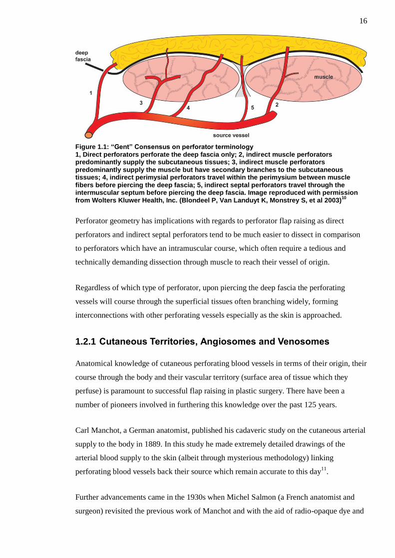
16
Figure 1.1: “Gent” Consensus on perforator terminology 1, Direct perforators perforate the deep fascia only; 2, indirect muscle perforators predominantly supply the subcutaneous tissues; 3, indirect muscle perforators predominantly supply the muscle but have secondary branches to the subcutaneous tissues; 4, indirect perimysial perforators travel within the perimysium between muscle fibers before piercing the deep fascia; 5, indirect septal perforators travel through the intermuscular septum before piercing the deep fascia. Image reproduced with permission from Wolters Kluwer Health, Inc. (Blondeel P, Van Landuyt K, Monstrey S, et al 2003)
10
Perforator geometry has implications with regards to perforator flap raising as direct
perforators and indirect septal perforators tend to be much easier to dissect in comparison
to perforators which have an intramuscular course, which often require a tedious and
technically demanding dissection through muscle to reach their vessel of origin.
Regardless of which type of perforator, upon piercing the deep fascia the perforating
vessels will course through the superficial tissues often branching widely, forming
interconnections with other perforating vessels especially as the skin is approached.
1.2.1 Cutaneous Territories, Angiosomes and Venosomes
Anatomical knowledge of cutaneous perforating blood vessels in terms of their origin, their
course through the body and their vascular territory (surface area of tissue which they
perfuse) is paramount to successful flap raising in plastic surgery. There have been a
number of pioneers involved in furthering this knowledge over the past 125 years.
Carl Manchot, a German anatomist, published his cadaveric study on the cutaneous arterial
supply to the body in 1889. In this study he made extremely detailed drawings of the
arterial blood supply to the skin (albeit through mysterious methodology) linking
perforating blood vessels back their source which remain accurate to this day11
.
Further advancements came in the 1930s when Michel Salmon (a French anatomist and
surgeon) revisited the previous work of Manchot and with the aid of radio-opaque dye and

17
x-rays (not available to Manchot at the time) made even more detailed anatomical
drawings of the various cutaneous territories of the body, whilst also including the
territories of the hands, feet, head and neck. He also went on to describe the various
interconnections between perforators to the skin and those occurring within muscles. The
significance of these highly detailed and influential vascular maps, provided by Manchot
and Salmon, were not however recognised at the time, perhaps because they were both
only published in the author’s native language of German and French respectively12
.
Coinciding with the emergence and growing popularity of free tissue transfer in the early
to mid-seventies; an effort to map potential donor sites in the body was undertaken by
Taylor and Palmer. They re-visited the works of Manchot and Salmon and undertook
cadaveric injection, dissection and radiographic studies. Whilst the work of Manchot and
Salmon was confined to the cutaneous vascular territory, Taylor and Palmer significantly
advanced this knowledge by offering a three-dimensional model of tissue perfusion
matching each source artery (and its accompanying vein) not only to the area of skin they
perfused but also their perfusion of the underlying deeper tissues. These three-dimensional
composite anatomical blocks of tissue were defined as angiosomes and the angiosomes of
the body are shown in Figure 1.213
.
18
Figure 1.2: The angiosomes of the body Image reproduced with permission from Elsevier Ltd. (Taylor and Palmer 1987)
13
This work was initially only studying the arterial supply (arteriosomes) of the body,
however, further research by the same team demonstrated that the venous supply
(venosomes) closely matched the arterial supply, further corroborating the angiosome
concept14,15
. As such each angiosome can be considered as consisting of a paired
arteriosome and venosome.
At the border of each angiosome they also identified a collateral arterial supply provided
by smaller calibre anastomotic connections between perforating blood vessels which link
adjacent angiosomes at all levels throughout the body. These connections were referred to
as “true” or “choke” anastomotic vessels. These interconnections linked through the
capillary bed mean that essentially every vessel in the body is connected in an unbroken
network. A similar picture was found in the venous architecture to compliment these
“choke” arterial anastomoses in the form of oscillating avalvular veins which connect the
valved venous systems to each other and allow bi-directional flow. Upon raising a flap, the
choke vessels linking the adjacent angiosome to the source vessel will dilate and it is
usually feasible that the choke vessel increase will allow immediately adjacent angiosomes
to be perfused safely, however, those out-with this area are subject to tissue necrosis13,16
. A

19
similar process occurs in the venous architecture allowing additional venous draining of
adjacent angiosomes through the linking avalvular oscillating veins. A schematic diagram
showing closed and open choke vessels is shown in Figure 1.3.
Figure 1.3: Diagrammatic representation of closed and open choke vessels
The maximum increase in choke vessel diameter is within the first 48-72 hours and is
complete by day 717
. This increase in vessel diameter is permanent and irreversible18
. The
proposed trigger mechanism for change in choke vessel calibre is thought to be due to
tissue hypoxia12
. These findings essentially explain why the traditional delay type
procedure (incising the borders of the proposed skin flap in a staged fashion rather than
raising the flap in a single stage) worked; as by staging the flap raising it allowed the
opening of adjacent choke vessels and improved perfusion to other areas of the flap.
The knowledge of three-dimensional vascular territories provided by Taylor and Palmer
essentially offer the reconstructive surgeon a map through which they can plan the type of
flap they require based upon reconstruction aims in terms of size, volume, constituents and
pedicle length.

20
1.2.2 Perforasomes
Further advances in the understanding of tissue perfusion in perforator flaps have been that
of the Perforasome concept. Saint-Cyr et al initially described the use of contrast enhanced
CT angiography coupled with cadaveric dissection to aid in the identification of the
vascular supply to perforator flaps19
. Building upon this initial work, they went on to
describe the concept of a perforasome as the three-dimensional area of tissue (vascular
territory) perfused by a single arterial perforator, rather than the global area of tissue
supplied by all the perforating vessels of a source vessel, as described by the angiosome
theory20
. (See Figure 1.4)
Figure 1.4: Common perforasomes of the body Image reproduced with permission from Wolters Kluwer Health, Inc. (Saint-Cyr et al. 2009)
20
They also identified that a perforasome was linked to each adjacent perforasome via direct
linking vessels or indirect linking vessels; in a similar fashion to that of true and choke
vessels as described by Taylor et al13,16
. The direct linking vessels are large vessels which
anastomose directly between perforators and can allow for capturing of multiple adjacent
perforasomes providing the flow/filling pressure through the original perforator is high.
The indirect linking vessels link adjacent perforasomes via their supply to the subdermal
plexus and recurrent flow20
. (See Figure 1.5)
21
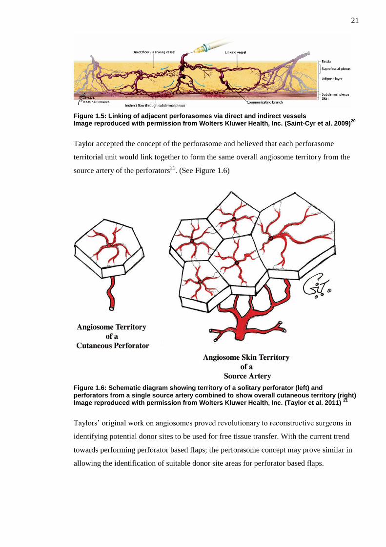
Figure 1.5: Linking of adjacent perforasomes via direct and indirect vessels Image reproduced with permission from Wolters Kluwer Health, Inc. (Saint-Cyr et al. 2009)
20
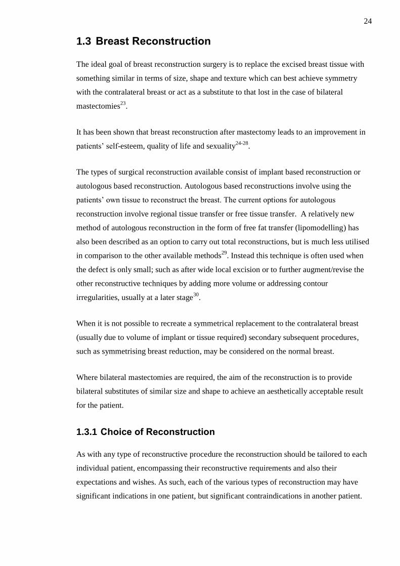
Taylor accepted the concept of the perforasome and believed that each perforasome
territorial unit would link together to form the same overall angiosome territory from the
source artery of the perforators21
. (See Figure 1.6)
Figure 1.6: Schematic diagram showing territory of a solitary perforator (left) and perforators from a single source artery combined to show overall cutaneous territory (right) Image reproduced with permission from Wolters Kluwer Health, Inc. (Taylor et al. 2011)
21
Taylors’ original work on angiosomes proved revolutionary to reconstructive surgeons in
identifying potential donor sites to be used for free tissue transfer. With the current trend
towards performing perforator based flaps; the perforasome concept may prove similar in
allowing the identification of suitable donor site areas for perforator based flaps.

22
1.2.3 Perforator flap perfusion physiology
Perfusion refers to the blood flow within specific organs or tissues, such as the skin and fat
of perforator based flaps. In normal physiological circumstances this should be a dynamic
process with the events following a continuous circuit.
Within a healthy perforator flap blood flow is characterised by high pressure input/supply
via arterial perforating vessels, subsequent microcirculation within the capillary bed and
low pressure output/drainage via the perforating veins.
In order to understand the perfusion within perforator flaps the basic physiological
principles of flow most be comprehended.
In its most simplistic form flow can be calculated using the following equation:
𝐹𝑙𝑜𝑤 𝑅𝑎𝑡𝑒 (𝑚𝐿/𝑚𝑖𝑛) = 𝐸𝑓𝑓𝑒𝑐𝑡𝑖𝑣𝑒 𝑃𝑒𝑟𝑓𝑢𝑠𝑖𝑜𝑛 𝑃𝑟𝑒𝑠𝑠𝑢𝑟𝑒 (𝑚𝑚𝐻𝑔)
𝑅𝑒𝑠𝑖𝑠𝑡𝑎𝑛𝑐𝑒 (𝑚𝑚𝐻𝑔 x (min/mL))
Or
𝑄 =∆𝑃
𝑅
Where the effective perfusion pressure (ΔP) is the mean intraluminal pressure at the
arterial end minus the mean pressure at the venous end (i.e. pressure difference) of the
vascular circuit22
.
Resistance to blood flow through vessels; however is a complex process dependent upon
multiple factors. Blood vessels are essentially cylindrical in nature and Poiseuille described
various factors known to influence the resistance to flow through a cylindrical tube. These
factors include the radius within the cylinder, the length of the cylinder; viscosity of the
fluid within the cylinder and the inherent resistance to the flow.
Incorporating these factors resistance (R) within blood vessels can be calculated using the
following equation:

23
𝑅 =8𝐿η
𝜋𝑟4
where L = vessel length, η = viscosity of blood, and r = radius of the vessel lumen.
By combining both equations into a single expression (commonly known as the Hagen-
Poiseuille Equation) it allows the calculation of blood flow:
𝑄 =∆𝑃𝜋𝑟4
8𝐿η
Where Q = Flow; ΔP = effective perfusion pressure; L = vessel length, η = viscosity of
blood, and r = radius of the vessel lumen.
In order to ensure adequate perfusion and thus perforator flap survivability each
component of the above equation has to be addressed. Effective perfusion pressure is
crucial and the successful completion of the microcirculatory process (delivering of
oxygen/nutrients to the tissues and removal of waste products) within the capillary bed is
dependent upon the existence of the high pressure (at arterial end) to low pressure (at
venous end) gradient and is essential for tissue survival. Failure of this process will lead to
tissue ischaemia and ultimately necrosis. Inadequate arterial supply will lead to tissue
hypoxia and ischaemia whereas inadequate venous drainage in the presence of an
appropriate arterial supply will result in an increase in venous resistance, loss of the
pressure gradient and failure of the microcirculatory process.
In general patients undergoing perforator flap surgery should be optimised peri and post
operatively ensuring that their blood pressure is adequate (to maintain a good effective
perfusion pressure) and they are kept well hydrated (to prevent an unwanted increase in
blood viscosity). With regards to the vasculature supplying perforator flaps it is apparent
that the radius of the supplying blood vessels is incredibly important and changes in this
factor will have huge influences on overall perfusion (i.e an approximate increase in vessel
radius of 19% will double blood flow). As such efforts must be taken during perforator flap
surgery to ensure that flaps are based on vessels of adequate calibre and that these vessels
are free from spasm or external compression.
24
1.3 Breast Reconstruction
The ideal goal of breast reconstruction surgery is to replace the excised breast tissue with
something similar in terms of size, shape and texture which can best achieve symmetry
with the contralateral breast or act as a substitute to that lost in the case of bilateral
mastectomies23
.
It has been shown that breast reconstruction after mastectomy leads to an improvement in
patients’ self-esteem, quality of life and sexuality24-28
.
The types of surgical reconstruction available consist of implant based reconstruction or
autologous based reconstruction. Autologous based reconstructions involve using the
patients’ own tissue to reconstruct the breast. The current options for autologous
reconstruction involve regional tissue transfer or free tissue transfer. A relatively new
method of autologous reconstruction in the form of free fat transfer (lipomodelling) has
also been described as an option to carry out total reconstructions, but is much less utilised
in comparison to the other available methods29
. Instead this technique is often used when
the defect is only small; such as after wide local excision or to further augment/revise the
other reconstructive techniques by adding more volume or addressing contour
irregularities, usually at a later stage30
.
When it is not possible to recreate a symmetrical replacement to the contralateral breast
(usually due to volume of implant or tissue required) secondary subsequent procedures,
such as symmetrising breast reduction, may be considered on the normal breast.
Where bilateral mastectomies are required, the aim of the reconstruction is to provide
bilateral substitutes of similar size and shape to achieve an aesthetically acceptable result
for the patient.
1.3.1 Choice of Reconstruction
As with any type of reconstructive procedure the reconstruction should be tailored to each
individual patient, encompassing their reconstructive requirements and also their
expectations and wishes. As such, each of the various types of reconstruction may have
significant indications in one patient, but significant contraindications in another patient.

25
Dispute, however, remains amongst the plastic surgical forum as to which reconstructive
technique provides the best results for patients and some surgeons advocate certain types
of reconstruction over others.
Recent evidence amongst larger studies would suggest that patients undergoing autologous
tissue breast reconstruction have higher satisfaction rates than those undergoing implant
based techniques24-26,31,32
. Furthermore it may be that those patients undergoing free
abdominal tissue breast reconstruction have the highest satisfaction33
and that these
patients are more satisfied with their breast from an aesthetic point of view in the long-
term in comparison to those undergoing implant based techniques24,26
.
This thesis will concentrate on autologous free tissue transfer and in particular the Deep
Inferior Epigastric Perforator (DIEP) Flap.
1.4 Free Autologous Tissue Breast Reconstruction
1.4.1.1 Donor Site Selection
In terms of donor site selection for reconstructing a defect; the ideal donor site would offer
completely the same mix of tissue to that which has been removed, whilst leaving a
suitable secondary defect which can be closed primarily or reconstructed, without
significant further deformity or insult to the patient. With regards to breast reconstruction,
the human female breast consists of primarily adipose (fat) tissue, glandular tissue and
skin. The proportion of breast glandular tissue varies throughout a woman’s lifetime and
undergoes significant atrophy upon aging. It would not be appropriate, in reconstructive
terms, to replace the removed glandular tissue with further breast glandular tissue. As such,
dependent upon the amount of skin removed at time of mastectomy, the donor site for
breast reconstruction would have to supply a suitable amount of soft tissue to replace the
removed glandular and adipose tissue with the option of a skin paddle if required.
Adipose tissue is the ideal replacement of composite breast tissue given its consistency,
rich vascular supply, texture and abundance within the human body. As with any type of
surgery, patient selection for each type of procedure is key and different patients will have
different volumes of adipose tissue in different areas of the body. There are a variety of
flap donor sites which can be utilised for breast reconstruction, ranging from regional flap
transfer options in the abdomen and back; to free tissue transfer options from the abdomen,
back, buttocks and thighs which in general offer good volumes of adipose tissue, option of

26
a skin paddle and a suitable blood supply for breast reconstruction. In some of the sites
muscle tissue also has to be taken to ensure blood supply or increase volume of tissue
available. Out of all the sites, in the majority of patients, the lower abdomen will offer a
good option for free tissue transfer, due to the abundance of skin, subcutaneous fat, reliable
blood supply and a defect that can generally be closed easily with acceptable scarring to
the patient.
1.5 Abdominal Blood Supply
The abdominal skin and fat receives a rich vascular supply from various sources. These
include perforating vessels from the intercostal muscles, the epigastric arcades (superficial
/ deep superior and inferior epigastric vessels), the superficial (and possibly deep
circumflex vessels) and to a smaller degree the superficial pudendal vessels as shown in
Figure 1.7.
Figure 1.7: Arterial supply to the anterior abdominal skin and fat
Huge anatomical variation exists between individuals as to the presence or absence of
these perforating vessels, their location, branching patterns, and their anastomoses.34
Constantly, however, the main vascular supply to the anterior abdomen comes from the
bilateral epigastric arcades consisting of the superficial and deep superior and inferior
27
epigastric vessels. Of note the superficial superior epigastric artery and vein are often
absent in humans and as such are usually disregarded anatomically.
The deep superior epigastric artery (commonly referred to as the superior epigastric artery)
arises from the internal thoracic artery at the level of sixth intercostal space and runs
anterior to the transversus thoracis muscle, passing inferiorly through the diaphragmatic
origins on the xiphoid process and costal margin remaining anterior to the transversus
abdominus muscle. It is initially deep to the rectus abdominus muscle but then perforates
the fascia branching diffusely and sending perforating vessels through the muscle to supply
it and the overlying soft tissue/skin. It is accompanied by the superficial epigastric vein /
venae comitantes which is a continuation of the internal thoracic vein / venae comitantes.
The deep inferior epigastric artery arises from the external iliac artery just superior to the
inguinal ligament. It travels through the extra-peritoneal tissue obliquely and in a medial
direction along the medial edge of the deep inguinal ring continually passing superiorly to
eventually pierce the transversalis fascia and enter the rectus sheath. As with the superior
epigastric artery at this level it branches widely and sends perforating branches through the
muscle to supply both it and the overlying soft tissue/skin. The artery is accompanied by
the deep inferior epigastric vein / venae comitantes which drains into the external iliac
vein.
The superficial inferior epigastric artery usually arises from the common femoral artery 2-
5cm inferior to the inguinal ligament as part of a shared trunk with the superficial
circumflex iliac artery; however other originating patterns can occur. It initially is deep to
the cribriform fascia, but as it approaches the inguinal ligament it penetrates through and
runs superiorly in the subcutaneous tissues. It is accompanied by venae comitantes, which
drain into the femoral vein, and also the superficial inferior epigastric vein, which runs
medial to the artery and drains into the saphenous bulb.
The main vascular supply to the anterior abdomen comes from the superior and deep
inferior epigastric system. Both these systems have diffuse anastomotic connections with
each other cranial to the level of the umbilicus at their terminal branches. It has been
shown that the deep inferior epigastric arterial system is the more dominant; providing a
more significant arterial blood supply to the anterior abdominal skin35
. The angiosome
supplied by the Deep Inferior Epigastric Artery (DIEA) can be seen in Figure 1.8.

28
Figure 1.8: Human angiosome map showing area supplied by DIEA Image reproduced with permission from Wolters Kluwer Health, Inc. (Taylor et al. 2011)
21
The number of main DIEA trunks can vary (between one and four) but they consistently
gives rise to a medial row and a lateral row of perforators through the deep fascia to supply
the anterior abdominal tissue36
. (See Figure 1.9)
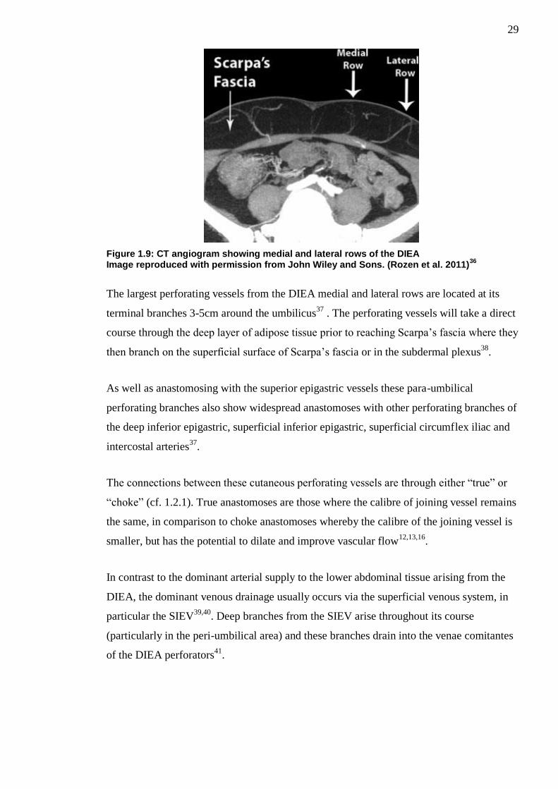
29
Figure 1.9: CT angiogram showing medial and lateral rows of the DIEA Image reproduced with permission from John Wiley and Sons. (Rozen et al. 2011)
36
The largest perforating vessels from the DIEA medial and lateral rows are located at its
terminal branches 3-5cm around the umbilicus37
. The perforating vessels will take a direct
course through the deep layer of adipose tissue prior to reaching Scarpa’s fascia where they
then branch on the superficial surface of Scarpa’s fascia or in the subdermal plexus38
.
As well as anastomosing with the superior epigastric vessels these para-umbilical
perforating branches also show widespread anastomoses with other perforating branches of
the deep inferior epigastric, superficial inferior epigastric, superficial circumflex iliac and
intercostal arteries37
.
The connections between these cutaneous perforating vessels are through either “true” or
“choke” (cf. 1.2.1). True anastomoses are those where the calibre of joining vessel remains
the same, in comparison to choke anastomoses whereby the calibre of the joining vessel is
smaller, but has the potential to dilate and improve vascular flow12,13,16
.
In contrast to the dominant arterial supply to the lower abdominal tissue arising from the
DIEA, the dominant venous drainage usually occurs via the superficial venous system, in
particular the SIEV39,40
. Deep branches from the SIEV arise throughout its course
(particularly in the peri-umbilical area) and these branches drain into the venae comitantes
of the DIEA perforators41
.

30
1.6 Abdominal Tissue Transfer in Breast Reconstruction
Autologous tissue transfer using abdominal tissue as a donor site has been used for
decades. The benefits of this site are the volume of tissue available for harvest, appropriate
colour match (when skin paddle required); good tissue pliability; robust vascular supply
and relatively low donor site morbidity.
These abdominal tissue flaps are based upon blood supply from the superior or inferior
epigastric vessels. Traditionally these flaps were pedicled based upon the superior
epigastric vessels and incorporated the rectus abdominus muscle along with the underlying
pedicle. However, as time progressed these flaps have evolved to be routinely based upon
the inferior epigastric vessels (the dominant anterior abdominal skin/fat blood supply as
discussed above) and rather than being pedicled, are raised as free flap alternatives, which
are transferred to the recipient site via microsurgical techniques. Furthermore the need to
incorporate the rectus abdominus muscle along with the pedicle during flap raising has
declined over time, with many choosing to raise the flap as a perforator based alternative.
1.6.1 TRAM Flap
The first use of a one stage abdominal based chest wall reconstruction was in 1974, when
Tai & Hasegawa described the use of a “transverse abdominal flap” consisting of skin and
fat from the upper abdomen, based upon the perforating vessels of the superior epigastric
artery and vein, to reconstruct the chest wall in 5 patients following radical operations for
recurrent breast cancer42
. However, these flaps were utilised solely for chest wall coverage
rather than the recreation of an aesthetic breast mound.
The first published description of breast reconstruction in terms of cosmesis (i.e. creating a
breast mound) by using an abdominal tissue based flap actually broke the trend mentioned
above in terms of historical evolution. Holmstrom, in May 1979, described an
experimental free tissue transfer reconstruction from the lower abdomen based upon the
deep inferior epigastric vessels, which he carried out on two patients43
. He termed this the
“free abdominoplasty flap” due to the fact that the overlying skin and fat was essentially
what was discarded at the time of an abdominoplasty. At this time, Holmstrom noted the
good vascular supply to the flap but commented on the precarious venous drainage, as
unfortunately the flap failed in one of these patients secondary to venous thrombosis.

31
A few months later, in October 1979, Robbins published his technique of using a pedicled
rectus abdominus myocutaneous flap to reconstruct a post-mastectomy wound44
. He used a
vertically orientated islanded flap, incorporating tissue from the upper and lower abdomen,
on the same side as the mastectomy defect based upon the superior epigastric vessels.
Drever45
and Dinner46
subsequently went on to publish their experience; techniques and
refinements on using a vertically based rectus abdominus myocutaneous type flap for
breast reconstruction.
In 1982, Hartrampf et al published their findings on using an ellipse of skin and fat
obtained from the lower abdomen for breast reconstruction47
. This transversely based flap;
which they named the horizontal lower rectus abdominus flap (more commonly referred to
as the Transverse Rectus Abdominus Myocutaneous (TRAM) flap in current literature)
could be harvested based upon the superior epigastric pedicle of either the ipsilateral or
contralateral rectus abdominus muscle to the mastectomy defect. They published their
success of such a flap in 8 patients and also discussed the successful use of this type of flap
in a bilateral breast reconstruction. They commented that this flap had advantages in terms
of easily hidden donor site scarring in the supra-pubic area and also that the superior
pedicle to the flap was well protected as it did not need to be identified. In this key paper,
they also discuss the vertical rectus abdominus musculocutaneous (VRAM) flap as
previously described by the authors above44-46
and provide another transverse alternative
(horizontal upper rectus abdominus flap) based upon the upper abdominal tissue, which
they reserved for patients with infra-umbilical scars. A diagram showing the various flaps
described is shown in Figure 1.10.
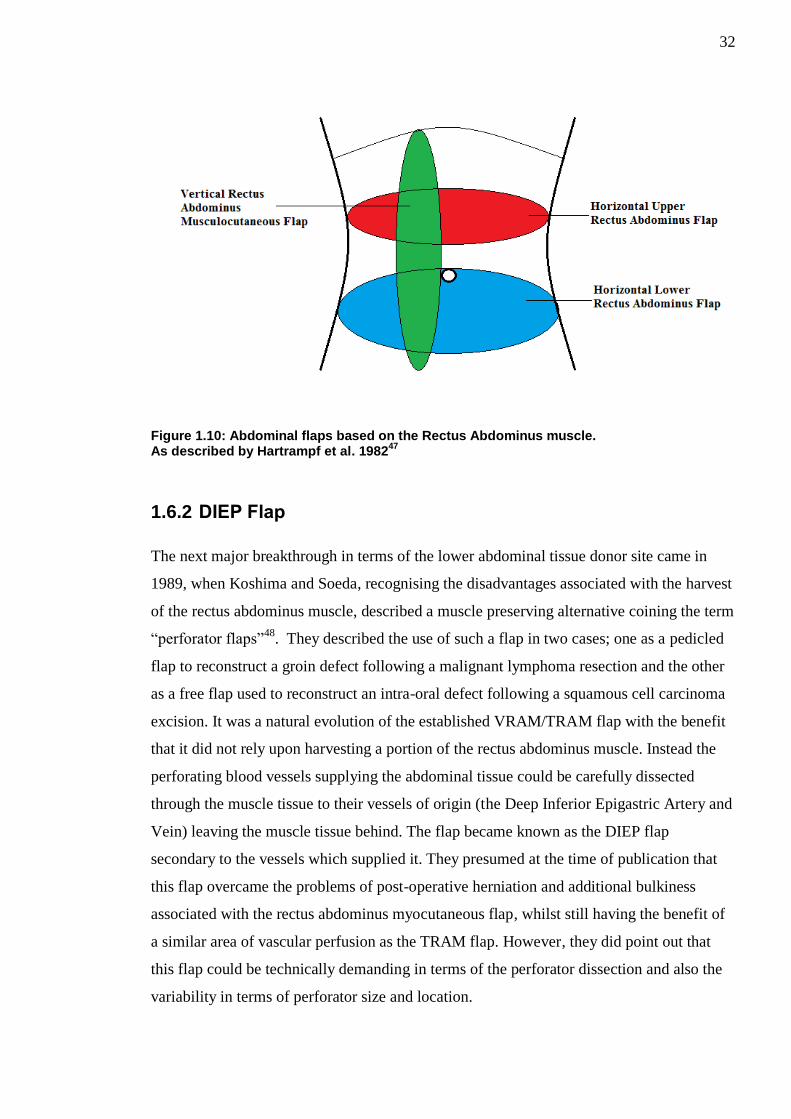
32
Figure 1.10: Abdominal flaps based on the Rectus Abdominus muscle. As described by Hartrampf et al. 1982
47
1.6.2 DIEP Flap
The next major breakthrough in terms of the lower abdominal tissue donor site came in
1989, when Koshima and Soeda, recognising the disadvantages associated with the harvest
of the rectus abdominus muscle, described a muscle preserving alternative coining the term
“perforator flaps”48
. They described the use of such a flap in two cases; one as a pedicled
flap to reconstruct a groin defect following a malignant lymphoma resection and the other
as a free flap used to reconstruct an intra-oral defect following a squamous cell carcinoma
excision. It was a natural evolution of the established VRAM/TRAM flap with the benefit
that it did not rely upon harvesting a portion of the rectus abdominus muscle. Instead the
perforating blood vessels supplying the abdominal tissue could be carefully dissected
through the muscle tissue to their vessels of origin (the Deep Inferior Epigastric Artery and
Vein) leaving the muscle tissue behind. The flap became known as the DIEP flap
secondary to the vessels which supplied it. They presumed at the time of publication that
this flap overcame the problems of post-operative herniation and additional bulkiness
associated with the rectus abdominus myocutaneous flap, whilst still having the benefit of
a similar area of vascular perfusion as the TRAM flap. However, they did point out that
this flap could be technically demanding in terms of the perforator dissection and also the
variability in terms of perforator size and location.

33
The first published description of the use of the DIEP flap in breast reconstruction was in
1994 by Allen and Treece49
. Recognising the benefits that such a flap could provide in
terms of the large volume of tissue available, they published their experience of using a
free DIEP flap for breast reconstruction in 15 patients. Over the subsequent years the flap
gained popularity worldwide with others, including Blondeel and Hamdi et al publishing
their experiences of utilising the flap to provide a successful breast reconstruction50,51
.
Since then the DIEP flap has become a workhorse flap for breast reconstruction with many
authors publishing their results in large series.
1.6.2.1 TRAM Flap vs DIEP Flap
The choice of a TRAM or DIEP flap is controversial amongst many surgeons.
Modifications to the TRAM flap since its conception have been to adopt a muscle/rectus
fascia sparing approach during flap raising, this involves harvesting only a small portion of
the rectus muscle and fascia around the perforating blood vessels rather than harvesting the
complete section of muscle. Advocates of this technique feel that it is at least comparable,
if not better, to the DIEP flap, since only a small portion of the muscle is removed with or
without a small portion of fascia then the recovery of the patient is likely to be better with
less chance of herniation whilst foregoing the time-consuming technical difficulty of
intramuscular pedicle dissection.
The literature varies greatly on the comparison between free TRAM and free DIEP flap
patients’ donor site morbidity. Despite the preservation of muscle tissue, as occurs in DIEP
flap raising, there is still the potential complication of donor site abdominal bulging to
occur, without any evidence of herniation. The rate of abdominal bulging post DIEP flap
transfer quoted varies in the literature between 0.7-5%52-54
. Nahabedian et al in 2005
attempted to ascertain whether risk factors such as previous abdominal surgery, diabetes
mellitus, age, bilateral reconstructions, smoking, previous childbirth, plication or mesh use
were associated with increased rates of abdominal bulging but the results were not
statistically significant55
. They did, however, find that previous pregnancy may have a
slightly protective mechanism to reduce the rate of abdominal bulging55
. Blondeel et al,
found that those patients having breast reconstructions with free TRAM flaps had a weaker
abdominal wall and higher rate of abdominal bulging, in comparison to those having free
DIEP flap breast reconstructions52
. This is in direct contrast to other authors who have
found no statistically significant difference between TRAM or DIEP flaps with regards to

34
hernia or abdominal bulging55-58
. Kroll also identified that it appears that DIEP flap
patients have a lower requirement for post-operative opiate analgesia and thus DIEP flap
donor sites may be less painful than those of TRAM donor sites59
. A meta-analysis in 2009
concluded, that patients with TRAM flap donor sites have a higher rate of abdominal wall
morbidity, in comparison to those with DIEP flap donor sites60
.
Another significant difference between the free TRAM and free DIEP flap is in terms of
their venous drainage. The classical DIEP flap venous drainage relies solely upon the
perforating (usually one or two) veins it has been raised upon. In contrast the free TRAM
flap, which is raised as a composite block including muscle rather than dissecting the
perforators free to their point of origin, will have a more abundant venous drainage system
as there are likely to be more venous perforators within the block of harvested tissue. As
such, venous congestion complications of free TRAM flaps are much rarer than those
experienced in free DIEP flaps61
.
With regards to flap related complications, it appears that the free TRAM is more robust
than that of the free DIEP flap and this may be due to the differences in their blood supply,
as discussed above. It has been well documented in some studies that there is a
significantly higher incidence of major flap complications in those patients undergoing
DIEP flap breast reconstruction57,58
. The same meta-analysis from 2009 also concluded
that there is a higher rate of flap related complications (such as fat necrosis or partial flap
loss) in those patients undergoing free DIEP flap surgery in comparison to free TRAM
flaps60
.
1.6.3 SIEA Flap
Another lower abdominal flap which can be used for breast reconstruction is that based
upon the superficial inferior epigastric artery (SIEA). This flap was first described in breast
reconstruction by Grotting in 199162
and, much like the DIEP, many others have since
advocated its use believing that it is the best option in terms of free lower abdominal tissue
flap for breast reconstruction63-65
. The benefit of the SIEA flap is that it requires no
intrusion into the rectus sheath and injury to the rectus abdominus muscle. However, the
anatomy with regards to the pedicle of this flap is extremely variable between patients and
studies have shown that in many patients the artery is unsuitable for microvascular transfer
or even completely absent (quoted absence between 13-51% and unsuitability between 13-
70% dependent upon the literature)65-67
. Many surgeons will routinely assess the
35
favourability of the SIEA flap during lower abdominal tissue harvest and if suitable
proceed with this flap rather than a TRAM/DIEP flap due to the ease of harvesting,
excellent donor site and rapid recovery of patients post-operatively65,67
. A proposed
algorithm based on their experience of 99 SIEA flap reconstruction by Speigel and Khan
suggests only proceeding with SIEA flap reconstruction if the artery diameter is >1.5mm68
.
However it has been reported that SIEA flaps have a much greater risk of flap related
problems in terms of necrosis, arterial complications, need for re-exploration and failure
rate in comparison to DIEP flaps69
.
1.6.4 Lower abdominal “zones”
Scheflan and Dinner were instrumental in providing a classification and division system as
to the blood supply to each part of the lower abdomen when raised as a flap based upon the
epigastric vessels. They published their results of using a uni-pedicled TRAM flap and
described a method of classifying different areas of the flap based upon their impression of
perfusion to each area. They divided the lower abdominal ellipse upon which the flap was
to be based into four equal areas which they named “zones”. Each zone of the flap was
numbered I-IV in terms of degrees of diminishing perfusion (i.e. Zone I best perfusion and
Zone IV worst perfusion). Zone I overlies the perforating vessels, Zone II is across the
midline adjacent to perforating vessels. Zone III is on the ipsilateral periphery to the
perforating vessels and Zone IV is on the furthest periphery on the contralateral side from
the perforators70,71
.
Despite this original description with regards to classification of perfusion zones being
carried out by Scheflan and Dinner, the zone’s became known colloquially as “Hartrampf’s
Zones” due to his previously published work on TRAM flaps47
. (See Figure 1.11)

36
Figure 1.11: Hartrampfs' Zones of Perfusion
In a subsequent publication by Dinner and Scheflan highlighting refinements in their
technique, they had changed their classification system by switching “Hartrampf’s zone
II/III72
. (See Figure 1.12)
Figure 1.12: Dinners' Zones of Perfusion
These zonal classification systems were originally designed specifically with regards to a
uni-pedicled TRAM flap based upon the superior epigastric vessels but they have become

37
universally adopted for the description purposes of flaps based upon the Deep Inferior
Epigastric Vessels in modern practice and literature.
Both classifications were based upon observations and clinical impressions rather than
scientific evidence. More recent studies assessing perfusion to the specific zones using
ultrasonography73
; Indocyanine green angiography74
and tissue oxygenation75
would agree
that Dinner’s revised zonal classification is more accurate, as perfusion does not appear to
occur as easily across the midline. Controversially, despite the revised publication by
Dinner advocating the change in Zone II/III, the original Hartrampf’s zones are still
commonly used.
Despite the disputes over the flap classification system in terms of using Hartrampf’s or
Dinner’s zones; there is no dispute with regards to the location and perfusion
characteristics of Zone I and Zone IV. For the purposes of this thesis Hartrampf’s classical
zones will be utilised in discussion.
The perforasome concept offers an alternative classification system. Rozen et al proposed a
perforasome type classification for lower abdominal perfusion when based upon a single
perforator from their findings in cadaveric dye injection studies and CT angiography76,77
.
This system divides the lower abdominal zones based upon whether a medial or lateral row
perforator has been used in flap raising. As with Hartrampf’s and Dinner’s Zones, Zone
IV remains the furthermost from the perforating vessel and the least well perfused. (See
Figure 1.13)
Figure 1.13: Perforasome Zones of perfusion based on medial (left) or lateral (right) row perforators Image reproduced with permission from John Wiley and Sons. (Rozen et al. 2010)
76

38
1.6.5 Vascular related complications associated with DIEP flaps
Despite the widespread use of the DIEP flap in breast reconstruction significant issues
associated with poor vascularity of the flap can occur.
1.6.5.1 Venous Congestion
When the venous return of a flap through the venous anastomosis is not adequate, then
parts of the flap or the entire flap can become congested; clinically presenting as a rapid
skin paddle capillary refill with subsequent swelling and discolouration of the flap skin
paddle. This is often the earliest sign of a failing flap and can signify that there may be a
problem with the venous anastomosis (i.e. thrombosis or kinking). This usually
necessitates an immediate return to theatre to assess the patency of the venous anastomosis
to the flap.
In the standard DIEP flap, the total venous outflow of the flap is directed through the
perforating venae comitantes accompanying the arterial perforator(s) chosen to base the
flap upon into the DIEV. Experimentally, it has been shown that venae comitantes are not
the best choices of venous drainage in free flaps and that draining veins should be situated
far enough away from the feeding artery to improve drainage78
.
Problems associated with venous congestion resulting in compromised perfusion to DIEP
flaps are well documented and it is the most likely vascular related complication.41,54,61,79-82
Excluding technical or unfavourable geographical problems (kinking) with perforator
dissection or the primary DIEV anastomosis, venous congestion in the DIEP flap can still
occur leading to potential partial or complete flap failure. Patent DIEV anastomosis with
concomitant venous congestion has been reported to arise between 2.1 to 27 percent of the
time in the literature53,61,83,84
.
The causes of venous congestion in the DIEP flap are poorly understood however several
theories as to why venous congestion occurs have been described, including inadequate
calibre of the perforating veins85
; inadequate venous midline crossover41,61,81
and an
inadequate communication between the superficial and deep venous system61,83
.
With regard to the calibre of the perforating veins Kroll suggested that in order to allow
adequate venous outflow in a DIEP flap then a perforating vein with a diameter of at least

39
1mm should be selected85
. However, this was only based on his own experience rather than
any anatomical or scientific research.
Others have theorised that inadequate midline crossover of the venous architecture in DIEP
flaps may be a significant risk factor in the development of venous congestion particularly
to Zone IV of the flap. In an anatomical injection study by Blondeel et al in 2000 they
found that communicating venous branches crossing the midline were absent in 36% of
specimens they examined and the only venous communications were via the subdermal
plexus61
. Arguably however, their study group was small consisting of only 15 cadaveric
and 3 abdominoplasty specimens and limited by the fact that they would be unable to
assess the contribution of the opening of oscillating veins in non-living specimens. A
similar anatomical study by Schaverien et al in 2008 also found absence of midline venous
crossover vessels in 1 out of 12 (8%) specimens they examined81
. A larger in-vivo study
consisting of 100 patients by Rozen et al in 2009 found an absence of midline crossover in
14% of the cohort41
.
The relationship of the deep and superficial vascular system is particularly interesting and
its importance has gained significant evidence in the literature over the past 15years.
Blondeel initially proposed that the venous communication between the DIEV and the
SIEV may be inadequate in patients with an SIEV >1.5mm and that in these patients the
superficial venous system is required to drain the flap61
.
Tran et al agreed with this proposition in their study to assess microvascular complications
of DIEP flaps and advocated that the SIEV should always be initially identified and
preserved as a “lifeboat vessel”. 11% of their DIEP flaps suffered intra-operative venous
congestion despite patent DIEV anastomosis and 45% of these required additional bypass
anastomosis to the SIEV to successfully salvage83
. They also suggested that a very small
diameter SIEV may be positive predictive indicator as it may correlate to a better
communication and a deep system dominant enough to drain the flap83
.
The most convincing evidence of the correlation between the deep and superficial system
was in a study published by Schaverien et al in 2010 assessing the relationship between
venous congestion and intra-flap venous anatomy in 54 DIEP flaps using contrast
enhanced MRA they found that DIEP flaps raised on venous perforators which lack a

40
direct communication with the SIEV system are significantly more likely (p<0.0001) to be
complicated by venous congestion86
.
1.6.5.2 Fat Necrosis
Fat necrosis can be classified as partial flap necrosis without any skin paddle changes.
This complication arises when areas of fat throughout the flap are not adequately perfused
however the overlying skin paddle still has an adequate blood supply and remains healthy.
This can occur weeks to months after the flap reconstruction and often presents as firm
lumps within the body of the reconstruction, non-healing wound edges plus or minus
discharge. Furthermore, this fat necrosis can be of particular distress to breast
reconstruction patients due to their history of breast cancer as they are often extremely
concerned with finding firm lumps within their reconstruction.
Some degree of fat necrosis can be considered a relatively common complication of DIEP
flap surgery, especially when larger flaps are required. The rate of fat necrosis associated
with DIEP flaps vary within the literature quoted anywhere from 2.8-17.1%85,87
. A recent
meta-analysis by Khansa et al in 2013, including 70 articles deemed suitable, found the
rate of fat necrosis in free DIEP flaps to be 14.4%88
.
However, the rate of absolute fat necrosis may be vastly higher than that actually
presenting clinically or being reported. A study by Peeters et al, showed that evidence of
fat necrosis was found ultrasonographically in 35% of all their DIEP flap patient cohort,
whilst only being clinically detectable by physical examination in 14%89
.
Despite the problems of fat necrosis, many of the patients can be managed conservatively
with reassurance and dressings if required. In the same study by Peeters et al, only 7% of
the 35% of their patients affected by fat necrosis required a return trip to theatre89
.
However, in patients with a large degree of fat necrosis a return to theatre for open
debridement or lipo-suction to the area may be required. Large volumes of fat necrosis can
lead to significant volume deficit of the flap, contour irregularities and the need for
subsequent revision procedures.
41
1.6.5.3 Flap Failure
Free flap failure is a catastrophic event for both patient and surgeon. It most commonly
occurs in the immediate/early post-operative period as a result of vascular compromise to
the pedicle of the flap. The causes of vascular compromise are usually attributed to
thrombosis at the site of micro-anastomosis of the artery or vein. Venous problems are
more commonly encountered and often are secondary to unfavourable pedicle geometry
(kinking of the pedicle), technical aspects of the anastomosis or due to external pressure on
the pedicle i.e. haematoma. Every effort is taken to ensure free flap survival with careful
tissue handling/dissection of the pedicle; meticulous microsurgical anastomosis techniques
and stringent post-operative care/monitoring of the patient and flap. Any evidence of flap
compromise should necessitate an immediate return to the theatre for evaluation of the flap
and pedicle anastomoses. Despite these interventions and precautions there is still a quoted
acceptable rate of free flap loss of up to 5%90
. With regards to the DIEP flap which has
become a popular well-established choice in modern microsurgical breast reconstruction
some experienced authors are quoting free DIEP flap failure rates of less than 1%. Gill et
al had a 0.5% flap failure rate their series of 758 free DIEP flaps for breast
reconstruction53
. This appears to be similar to that quoted for free TRAM flaps as shown
by Vega et al who quoted a free flap failure rate of 0.3% in their series of 500 free TRAM
flaps91
.
Late free flap failure (that occurring after 7 days) is incredibly rare and is often associated
with infection or recurrence of tumour at the recipient site92
.
1.6.6 Vascular augmentation of DIEP flaps
Regardless of the cause of venous congestion, a number of studies have attempted to
salvage congested DIEP flaps through the use of vascular augmentation, by anastomosis of
an additional vein50,61,80,82-84,93-100
.
Flap vascular augmentation procedures are often referred to as “supercharging” or
“turbocharging” of the flap depending upon the vascular configuration of the additional
anastomosis(es). This nomenclature however can be confusing and the terms are often
incorrectly used interchangeably in clinical practice or even in the literature. A useful
analogy to remember the terms and configurations they describe was provided by Semple,
who suggests thinking of flaps like an engine in a motor vehicle. Supercharging refers to
boosting the engines performance from an external source and turbocharging refers to

42
using the engines own exhaust to provide additional power101
. These are the generally
accepted definitions in current practice102,103
. An example to illustrate “supercharged” and
“turbocharged” flaps is shown in Figure 1.14.
Figure 1.14: Illustration representing a supercharged and turbocharged flap Note the lower right image refers to the use of an inter-positional vein graft. Image reproduced with permission from Wolters Kluwer Health, Inc. (Hallock 2000)
102
However, further disparity exists as to whether the terms “supercharging” or
“turbocharging” should be used for only additional arterial anastomosis(es) or venous
anastomosis(es) and which terms should be used when.
Given the difference in expert consensus opinion regarding the terms, and indeed what
they imply, in an effort to reduce confusion within this thesis the terms “supercharging”
and “turbocharging” will not be utilised. Instead the terms arterial augmentation; venous
augmentation and combined arterial/venous augmentation will be used to clearly explain
when an additional arterial input, additional venous output or combined arterial/venous
input/output is used respectively.
Whilst the use of vascular augmentation has been documented widely in DIEP flap surgery
over the past 15 years, the evidence is limited to isolated case reports or case series based
upon salvage procedures performed once venous congestion has already occurred.

43
In one of the early large case series of DIEP flap breast reconstructions Blondeel described
his experience of the first consecutive 100 flaps performed50
. He was the first to describe
venous augmentation of the DIEP flap via an external source. He mentions in the
discussion of this paper that two obese patients had inadequate venous drainage and that
the problem was overcome through vascular augmentation, using a free arterial
transposition graft between the SIEV and the venae comitantes of the IMA. Shortly after
Villafane et al went on to describe a similar successful salvage using a saphenous vein
interposition graft from the SIEV to circumflex scapular vein labelling the SIEV as a
“lifeboat ”100
.
Wechselberger et al in 2001 published the benefits of venous augmentation from their
experience of 37 free DIEP flap breast reconstructions. In 3 of these flaps they noted
significant venous congestion despite patent anastomosis of the main DIEV to the IMV.
These flaps were salvaged by venous augmentation by anastomosing the SIEV to an
additional recipient vein out-with the flap in a procedure they termed “venous
superdrainage”84
. A number of other surgeons have since described their salvage of
congested free abdominal flaps utilising venous augmentation of the flap by anastomosing
DIE venae comitantes or the flap SIEV to various other recipient veins including the
perforating intercostal82
, chest wall83
, thoracodorsal97
, cephalic80,97
,basilic93
, lateral
thoracic84
and even external jugular veins97
.
Utilising components within the flap to augment venous drainage has also been described
as a method to salvage the congested DIEP flap. Rohde and Keller initially described their
technique of DIEP flap salvage by anastomosing the ipsilateral SIEV to the proximal end
of one of the flap venae comitantes99
. Liu et al in 2007, then described a similar technique
of salvage but in a reverse-flow pattern by anastomosing the ipsilateral SIEV of the flap to
the distal end of one of the flap venae comitantes providing additional reverse flow venous
drainage95
. However, concerns were raised about the reverse flow technique as potential
valves present within the vein may prevent retrograde flow98
.
Recognising the need for venous salvage procedures in those flaps showing intra-operative
venous congestion, despite patent venous anastomosis and no clear consensus in the
literature Galanis et al proposed an elegant intra-operative algorithm in 2014104
. (See
Figure 1.15)

44
Figure 1.15: Suggested algorithm for management of intra-operative venous congestion Image reproduced with permission from Wolters Kluwer Health, Inc. (Galanis et al. 2014)
104
Some surgeons have started to routinely carry out venous augmentation procedures on their
flaps, in an effort to reduce the risks of venous congestion.
Enajat et al in 2010, published the results of a large retrospective study of 564 consecutive
DIEP flap cases performed by four surgeons comparing those DIEP flaps which had one
venous anastomosis (273) versus those flaps (291) which at the time of the original
operation had an additional primary venous anastomosis to either a second venae
comitantes or the SIEV105
. In this study they found that use of two venous anastomoses
significantly reduced the number of cases of post-operative venous congestion (0 flaps) in
comparison to the group which only had one venous anastomosis (7 flaps) without
increasing overall complication rate. They recommend that where possible all flaps should
have an additional venous anastomosis performed. Whilst this is a large study comprising
of 564 flaps, it is inherently flawed by the fact that it was retrospective in nature and the
cohorts were not randomised. The choice to perform a primary second venous anastomosis

45
was on an individual surgeons’ preference and one of criteria for performing a second
primary anastomosis was intra-operative suspicion of venous congestion.
Boutrous in 2013 published his similar opinion that where possible all DIEP flaps should
have double system (deep and superficial) venous drainage79
. In his case series of 352 free
DIEP flaps used for breast reconstruction he performed an additional venous augmentation
procedure in 311 of the flaps by additionally anastomosing the SIEV from the DIEP flap to
an internal mammary perforating vein or internal mammary venae comitantes. Out of the
double venous drainage cohort there was one flap requiring return to theatre for venous
congestion (0.3%); in the remaining 41 single venous drainage flaps two required return to
theatre (4.9%). He believed this was a statistically significant reduction however
comparison between both groups is difficult due to the completely different cohort sizes
and also the fact that those patients in the non-double venous drainage group could be
considered as having non favourable venous anatomy to begin with if the original venous
augmentation procedure was not possible.
Whilst all instances above represent venous augmentation to treat venous congestion,
arterial augmentation can also be performed to improve arterial flow, however, this is often
not an issue in a standard DIEP flap.
1.7 Assessment of DIEP flap flow/perfusion
Laser Doppler Flowmetry and ICG angiography are two well established non-invasive
methods of assessing superficial flap blood flow/ tissue perfusion. Ultrasonic transit time
flowmetry provides an invasive measurement of intravascular blood flow. These
techniques were used in the methodology of this thesis and will be discussed in detail
below.
1.7.1 Laser Doppler Flowmetry
In 1964 Yeh and Cummins carried out an experiment using a continuous wave helium
neon laser beam directed at small polystyrene spheres immersed in water. They
demonstrated that the scattering of the laser light which occurred could be measured and
utilised to assess flow within fluids using the principle of the Doppler shift effect106
. After
the initial discovery another group of researchers working at Brown Engineering Company
(Huntsville, Alabama) realised the technique could be used not only to assess flow rates
within fluids but also within gases and designed a machine capable of measuring this

46
which they called a Laser Doppler Flowmeter107
. The advantages of this technique became
widely apparent as it offered a reliable, accurate non-invasive method of measuring flow
even at low velocity.
1.7.1.1 History of Laser Doppler Flowmetry in Plastic and Reconstructive Surgery
In 1975 Stern was the first to use Laser Doppler Flowmetry to assess skin perfusion in
humans. He realised that the technique offered a rapid method by which to assess changes
in skin perfusion and foresaw potential clinical applications in assessing patients with
vascular disease and also the “assessment of the viability of burns and grafts108
. Sterns’
initial predictions were correct and the technique became established in the medical world
for a variety of specialities ranging from rheumatology to plastic surgery. In plastic surgery
the use of Laser Doppler Flowmetry has become well established in the burn subspecialty
to aid in the estimation of burn depth109-111
and in the microsurgery subspecialty to aid in
the monitoring of free flaps112-116
.
1.7.1.2 Principles
Laser Doppler is a non-invasive technique which allows the measurement of superficial
microvascular blood flow within tissues.
In the assessment of skin perfusion it operates generally upon the following principles.
Laser light (usually in the near-infrared/infrared spectrum) is generated and directed at the
target tissue from a stationary point. Upon contact the laser light will have several
interactions with the target tissue including absorption, transmission, scatter and reflection.
The scattered and reflected laser light energy from the tissue can be measured using
specialised photoreceptor sensors within a receiver. The scattered and reflected laser light
energy will have different characteristics dependent upon the type of tissue it interacts
with. Interactions with static tissue will produce much less scattering of the laser light and
thus will have a lesser effect upon the frequency of the reflected beam. However
interactions with moving tissue (such as red blood cells moving within intravascular
spaces) will produce a greater degree of scattering and thus broaden the frequency of the
reflected laser beam known as the doppler shift effect. The difference between the
frequency of the reflected laser light from static tissue and that occurring from moving
tissue is detected by the receiver and the velocity of the moving tissue (i.e. red blood cells)

47
calculated thus allowing a measure of blood flow and in turn; perfusion of the tissue to be
calculated.
The perfusion of the tissue as obtained by laser doppler measurement is commonly
expressed as “flux” (which is the number of red blood cells multiplied by their velocity)
and this in turn is converted to arbitrary perfusion units by software within the laser
doppler machine often in graphical displays which allow statistical comparison between
different areas of interest.
1.7.1.3 Methods of Laser Doppler Measurement
The laser light energy can be delivered to the target in two ways.
The laser light energy can be delivered (from a distance) to the target tissue via a low
intensity focused laser light beam which is scanned across the target area using moveable
mirrors and the resultant “doppler shift” assessed (from a distance) via photoreceptor in the
receiver. This technique is known as Laser Doppler Imaging (LDI) or “scanning laser
doppler” and allows relatively large areas of tissue to be measured in a short period of
time.
Another method of delivering the laser light energy is via optic fibres. Generated laser light
is transmitted from the source via an afferent optical fibre to an optical probe which must
be in direct contact with the target tissue. As well as the afferent optical fibre terminating
in the probe there is usually one or more efferent optical fibre(s) originating from the probe
which capture the scattered and reflected laser light from the tissue and transmit it to
photoreceptors in a receiver allowing the doppler shift and thus blood flow to be
calculated. This technique is known as Laser Doppler blood flow monitoring. As a result of
the probe being in direct contact with the tissue and the relatively short distance between
the afferent and efferent fibre(s) only the blood flow within relatively small areas of tissue
can be measured; albeit very accurately. This technique is useful for measuring blood flow
in areas which are difficult to access using a laser beam (i.e. within body cavities).

48
1.7.2 Indocyanine Green Angiography
1.7.2.1 History of Indocyanine Green Angiography
Indocyanine Green (ICG) is a tricarbocyanine dye initially developed as a cyan forming
layer in the production of Technicolor film by Dr Brooker and Heseltine of the Eastman
Kodak Research Laboratories.
In 1955 an executive of Eastman Kodak Research Laboratories was a patient undergoing
treatment by cardiologist Dr Irwin Fox at the Mayo Clinic. Coincidentally at the same time
Dr Fox was searching for a biocompatible dye that could be detectable in blood and
recruited the aid of his patient in this search. The executive sent a variety of dyes to Dr Fox
for evaluation; amongst which ICG was one. The ICG dye met the characteristics which Dr
Fox required; however it was very unstable in its aqueous form. Subsequent refinements to
the dye were undertaken by a pharmaceutical company (Hynson, Westcott & Dunning Inc.
Baltimore, Maryland) producing a stable lyophilised form and Dr Foxs’ team began further
trials117
.
Initially ICG dye was used in assessing cardiac output118
and then hepatic blood
flow/function.119
It was not until 1969 that the first use of ICG in absorption angiography
was undertaken by Kogure et al when they obtained detailed images of the cerebral
vasculature of a canine brain 120
and subsequently fundus circulation in a monkey121
. These
early angiography studies relied upon invasive intra-arterial injections of ICG as it was
believed that intravenous injections of the dye failed to obtain acceptable results and as
such was not deemed appropriate for human use.
Hochheimer described a technique using ICG dye intravenously in cats for near-infrared
absorption angiography purposes in 1971122
solving the requirement for intra-arterial
administration and in conjunction with Flowers’ went on to describe the first successful
human near infra-red absorption angiography imaging of large choroidal vessels using ICG
the following year123
.
Further research and improvements upon their technique; altering the concentrations of dye
and camera systems, led to the development of near-infrared fluorescence angiography
using ICG dye allowing visualisation of the smaller blood vessels within the eye and blood
flow within them124
. The potential application of the ICG angiography process in

49
obtaining detailed images of the vasculature of the human eye were quickly realised and
the technique has been used extensively in the speciality of ophthalmology since125
.
Further to the successful medical uses of ICG angiography listed above, interest began to
grow for the potential application of the technique in surgery when Raabe et al described
the first use of ICG angiography intra-operatively to assess real time blood flow through
the vasculature in neurosurgical procedures126
. Since then further applications of the
technique have been found in not only Neurosurgery but Cardiac; Vascular; Oncological;
Hepatic; Breast and Plastic and Reconstructive surgery127
.
1.7.2.2 Indocyanine Green Angiography in Plastic and Reconstructive Surgery
In a specialty such as Plastic and Reconstructive Surgery where fundamental knowledge of
the vascular perfusion of tissues is essential it is of no surprise that ICG angiography
should have an established role.
Rubben et al first alluded to the potential use of ICG angiography in Plastic and
Reconstructive surgery when they published their successful experimental results of using
ICG angiography to assess skin flap perfusion in animal models and a select patient cohort
in 1994128
. However, it was not until 8 years later when Holm et al. utilised the technique
to intra-operatively assess the perfusion/viability of skin flaps129
and the post-operative
monitoring of free flaps130
that ICG angiography became popular in the speciality. Since
then a wide variety of applications in the realms of plastic surgery have been found not
only in the design and assessment/monitoring of flaps but also in terms of
lymphography131
; sentinel lymph node biopsy132
and burn depth estimation133
.
1.7.2.3 Principles
ICG dye absorbs energy in wavelengths of the electromagnetic spectrum between 600-
900nm and fluoresces strongly when exposed to wavelengths between 750-950nm. Upon
injection into the living human circulation ICG dye rapidly binds to plasma proteins
(predominantly albumin) and remains confined to the intravascular space circulating
around the body.
By utilising a laser light source emitting energy in the wavelength between 750-900nm the
dye will fluoresce. This fluorescence is not visible to the human eye however can be

50
detected by an appropriate optical video detector and the real-time images recorded. The
laser light source and detector are usually coupled within the same machine allowing
simultaneous fluorescence and detection. The half-life of the dye in human circulation is
very short at between 150-180seconds134
and thus the capture sequence must be
commenced soon after injection. As a result of the rapid excretion of the dye; repeated
measurements can be taken after alteration of variables without risk of artefact or having to
wait for long periods of time in contrast to fluorescein which can take up to 18 hours to
clear135
.
A laser of the appropriate wavelength and a fluorescence detector can be used to allow
real-time visualisation of blood flow. Metabolisation of the dye occurs solely via the liver
parenchymal cells and the by-products are excreted via bile salts; no cellular absorption
occurs and thus toxicity is low136
.
1.7.3 Intravascular flow measurement using ultrasonic transit-time flow meter
1.7.3.1 History of ultrasonic transit-time flow meters
The first ultrasonic transit-time flowmeter was invented by Franklin et al and described in
a paper published in 1962 in which they discussed the potential of their invention and that
it could allow flow within a blood vessel to be continuously measured137
. However it was
not until 1978 that Drost described the theoretical basis of the transit-time volume flow
principle through which these devices could accurately measure the velocity of fluids 138
.
The advantages of ultrasonic transit-time flow measurement is that the probes utilised do
not require to be in direct contact with the vessels being assessed and are not influenced by
vessel internal/external diameter, vessel shape or the blood flow profile. The recordings
obtained via the technique are stable and calibration is also unnecessary as there is little
zero-drift from baseline139
.
1.7.3.2 Principles
Intravascular flow can be detected through the process of transit-time ultrasound flow
theory. This theory dictates that when ultrasonic energy moves from a point of origin to a
destination through a flowing liquid (in this case blood) the time taken to reach the
destination is altered. If the ultrasonic energy is moving with the direction of flow transit
time is decreased and conversely if the ultrasonic energy is moving against the direction of

51
flow transit time is increased. Providing that the distance between the point of origin and
destination is fixed and the normal transit-time between these two points known, then by
measuring changes in transit time occurring secondary to the liquid through which the
ultrasonic energy is passing, it allows the calculation of liquid velocity.
1.8 Volume/skin requirements in DIEP flap transfer and associated problems with Zone IV
Acceptable outcome in DIEP flap breast reconstruction is not solely based upon successful
flap transfer but also upon being able to transfer an adequate volume of tissue to shape
such tissue to meet the reconstructive needs of the patient.
On the occasions when large volume reconstructions are required (i.e. large contralateral
breast), large skin paddles required (delayed breast reconstructions) or reconstructions
requiring additional projection (less ptotic breast) then the majority of the lower abdominal
pannus may be required as a donor site. As an example Zone IV can be useful to provide
more volume and skin particularly when performing delayed reconstructions of large
breasts.
Despite the widespread utilisation of the free DIEP flap in breast reconstruction there are
well recognised flap related vascular complications41,54,61,79,80,82-84,86
. This is particularly
true of Zone IV as it is the area of the flap which receives the least perfusion/drainage from
the perforating vessels and is therefore the most likely to suffer from perfusion related
issues such as ischaemia, venous congestion and fat necrosis. Despite some authors
reporting variable success with the inclusion of Zone IV in their DIEP flaps61
others have
commented that Zone IV almost always suffers from problems83
. In addition there is the
belief that inclusion of Zone IV may compromise the overall arterial perfusion to the other
Zones of the DIEP flap83
. Secondary to this many surgeons routinely excise and discard
Zone IV from the DIEP flap prior to flap transfer to the defect site. As a result the volume
of the DIEP flap available for transfer is reduced by approximately 15-20% and can be
difficult to shape to fit the geometry of a natural breast.
There are various strategies described to increase the volume/projection of free DIEP flap
breast reconstructions including dividing the DIEP flap in the midline and “stacking” each
hemi-flap on top of each other140-142
; stacking an SIEA flap on top of a hemi-DIEP

52
flap142,143
or in the extreme stacking a Superior Gluteal Artery Perforator (SGAP) or
Profunda Artery Perforator (PAP) flap on top of a DIEP flap144
.
However, these procedures all have a significant learning curve in terms of arranging flap
and pedicle geometry, require additional dissection; require additional operating time or in
the case of the stacked DIEP/SGAP/PAP flap combinations an additional donor site out-
with the abdomen.
Others advocate delayed augmentation of DIEP flaps using lipomodelling as the simplest
method to address any volume deficiencies or contour irregularities145,146
. However, this
often leads to the requirement of multiple additional procedures for the patient.
If Zone IV of the DIEP flap could reliably be included without increasing the risk of flap
related complications then this may allow surgeons the necessary volume or skin paddle
required for reconstruction rather than having to resort to additional or second stage
procedures.
1.8.1 Pro-active vascular augmentation of DIEP flaps
Vascular augmentation of the DIEP flap through the additional anastomosis of an extra
artery / vein or both at the time of the original operation is another option to potentially
improve blood supply to the flap and increase prospective flap volume.
Whilst most vascular augmentation procedures are performed as salvage to treat the
congested DIEP flap (cf. 1.6.6), some authors are now proposing pro-active vascular
augmentation of DIEP flaps to improve blood flow to the flap or to increase the size of the
flap which can be taken. Such procedures have previously been described to augment the
blood supply of TRAM flaps101,147-152
but are only recently being described exclusively in
DIEP flap breast reconstructions.
The first cases of vascular augmented DIEP flaps for breast reconstruction were actually
described in 2002 by Mu et al who performed 5 cases of vascular augmented DIEP flaps
using both ipsilateral and contralateral DIE vessels attached respectively to the proximal
and distal ends of the IM vessels153
.
However it was not until 2007 when Hamdi et al later described their use of vascular
augmented DIEP flaps that the technique received widespread acknowledgment154
. In their

53
series of 16 free DIEP flap breast reconstructions inclusion of all Zones of the flap was
required secondary to the need for a large volume reconstruction or issues with abdominal
vascular supply (i.e. previous scarring on one side of the flap). Various augmentation
configurations were utilised in this case series. 13 of the flaps underwent vascular
augmentation procedures using the IM vessels to supply the main pedicle and various
intra-flap anastomoses. The remaining 3 flaps had vascular augmentation procedures using
the thoracodorsal vessels attached to a secondary pedicle to provide blood supply to the
flap in addition to the main pedicle IM vessel anastomoses. Hamdi et al also attempted to
provide a classification system for the various types of flap configurations. (See Figure
1.16)
Figure 1.16: Proposed classification system for abdominal perforator flap and vascular augmentation configurations Image reproduced with permission from Elsevier Ltd. (Hamdi et al. 2007)
154
Since the description by Hamdi et al a variety of other authors have reported their
experiences in providing large volume reconstructions with vascular augmented DIEP
flaps and suggested various modifications to the above classification system155-161
.

54
1.9 Potential concerns of vascular augmentation of abdominal flaps
There are numerous documented cases concerning the use of vascular augmented flaps;
mostly as a salvage procedure to improve venous drainage in congested flaps 50,61,80,82-84,93-
100, or as an attempt to utilise larger more robust flaps
101,147-158,160,161. However, the results
of these cases are simply reported in terms of free flap survival or failure with little in the
way of scientific evidence supporting their use.
Whilst the experimental animal studies have provided some evidence that vascular
augmentation of abdominal flaps in rats leads to increased areas of flap survival; these are
all post-operative outcome assessments with no account for the in-vivo effects on blood
flow or perfusion occurring at the time of augmentation procedure162-167
. Also it would
appear from some of these experimental studies that arterial augmentation is more
important than venous augmentation166,167
.
Though it may seem logical that increasing the number of blood vessels used to supply a
flap will lead to an increase in flap perfusion and improvement in flap outcome; recent
evidence has shown that counter-intuitively this may not be the case. An elegant
experimental animal and in-vivo human study was published by Douglas et al in 2014
assessing the effect of perforator number and location on total pedicle blood flow and on
Zone IV skin and fat perfusion of DIEP flaps168
. In the first part of this study carried out on
twenty abdominal flaps in rats they found that there was a significant decrease in main
pedicle blood flow when the flaps were based on more than a solitary perforator. In the
second part of this study they assessed in-vivo using LDI and ICG angiography the effect
of perforator number on Zone IV perfusion and interestingly found that basing flaps on
more than one perforator resulted in significantly lower perfusion to Zone IV of the flap. In
their discussion they suggest that their findings could be accountable to changes in
pressure gradients within the flap and that by adding additional perforators the overall
venous filling pressures to this area of the flap are reduced resulting in poorer perfusion.
The results of this study would corroborate the findings published by Gill et al in 2004 in
which they found a significant positive correlation between increasing the number of
perforators used to supply flaps and flap related complications, including partial flap loss,
in a retrospective review of 758 DIEP flaps53
.

55
1.10 Outcomes of DIEP flap breast reconstruction
The outcome of DIEP flap surgery is due to far more than flap survival or the presence or
absence of any of the potential complications discussed previously. Although complete or
partial flap failure in itself is an important outcome better measures are now required for
audit and in many areas justification of funding. Given the primarily aesthetic aim of breast
reconstruction; i.e. replacing the excised breast tissue for something similar in terms of
size, shape and volume; then the major outcomes are patient satisfaction and post-operative
cosmesis.
1.10.1 Patient Reported Outcome Measures
Traditional outcome assessment in the field of Plastic Surgery has focussed on
surgeon/peer opinion and analysis of photographic evidence or complication rates.
However, whilst this data is important to consider, it fails to take into account individual
patient perceptions of the surgical results and the profound effect that surgical
interventions can have on a patients’ quality of life. In an effort to address this issue
specially designed questionnaires, known as Patient Reported Outcome Measures
(PROMs), have been developed that quantify health-related quality of life and/or other
significant outcome variables (e.g., satisfaction) from the patient’s perspective169
. The
results obtained via these questionnaires have become increasingly important in clinical
practice and also plastic surgery research.
Whilst capturing of any patient response to treatment is crucial, in order to ensure their
satisfaction with the results, it is important to do so in a reliable and reproducible manner.
Concerns have been raised that in plastic surgery research many of the studies using
PROMs to assess surgical outcome have utilised questionnaires which have not been
adequately validated or designed according to established guidelines170
. The development
of validated PROM questionnaires with particular reference to the population that they are
assessing rather than generic questionnaires is paramount to ensure that the data observed
is reliable.
Studies assessing the outcomes of breast reconstruction and breast aesthetic surgery lend
themselves well to the use of PROMs as it is well established that overall patient
satisfaction is the most important factor in determining the success of any form of surgery
dealing with aesthetics171
. However, a systematic review by Pusic et al in 2007 highlighted

56
that there were major issues with the PROM questionnaires used in the field of breast
surgery as only seven of two hundred and twenty three studies utilised appropriate
psychometrically validated PROMs for a breast population172
. The use of such generic
questionnaires in a breast population can lead to a lack of sensitivity, failing to identify
specific problems encountered by breast surgery patients, over-estimating treatment effects
and leading to reporting bias173
.
The BREAST-Q, developed in 2009 by Pusic et al, is a PROM questionnaire designed to
study the impact and effectiveness of breast surgery from the patient perspective174
. It
covers six domains involved in breast surgery; satisfaction with breasts, overall outcome,
process of care, and psychosocial, physical and sexual well-being. It can be utilised in a
modular fashion for breast augmentation, reduction or reconstruction. Since its
introduction in the plastic surgery literature the BREAST-Q has become well validated in
breast research and outcome-reporting175
.
With regards to the superiority of abdominal based reconstruction versus the other
treatment options, utilising PROMs as an assessment tool, there is much conflicting
evidence in the literature.
A retrospective study of by Alderman et al in 2000 assessing determinants of patient
satisfaction after breast reconstruction found that in the 212 patients those opting for
autologous based abdominal flap reconstructions were more than twice as likely to be
satisfied with their reconstruction than those patients with implant based reconstructions25
.
Similar retrospectives studies by Christensen et al26
and Saulis et al31
assessing the
outcomes of 263 and 268 women respectively found that women who had opted for
autologous reconstruction over implant based reconstruction were significantly more
satisfied with their reconstruction.
In a large study by Yueh et al in 2010 comparing outcomes of 538 patients undergoing
various types of autologous flap (TRAM, DIEP or LD) or implant based breast
reconstructions. They found that patients undergoing DIEP flaps had the highest
satisfaction rates and that 80% of all DIEP patients were happy with their reconstruction33
.
This corresponds to the results of a study by Damen et al who reviewed satisfaction rates
after DIEP flap breast reconstruction and found that in the 72 woman they reviewed 94%
were satisfied with the appearance of their breast reconstruction when dressed and 89% felt
that the reconstructed breast felt like their own176
.

57
Other studies have shown that there may be no real difference in satisfaction or that
implant based reconstructions may have higher rates of patient satisfaction. In a study of
206 patients by Andrade et al they could find no difference in terms of patient satisfaction
between implant or autologous tissue reconstruction177
. A later study by Fogarty et al in
2004, assessing patient satisfaction after TRAM flap reconstruction or implant based
reconstruction found similar results, in that whilst the mean patient satisfaction in the
TRAM group was higher than the implant group, it did not reach statistical significance178
.
However, this study was small consisting of data comprised from only 57 patient
questionnaires. In a larger study of 168 patients, Spear et al found that patients with
implant reconstructions had the highest satisfaction scores in comparison to those with
autologous based reconstructions179
.
1.10.2 Aesthetic Outcome
Advocates of DIEP flap breast reconstructions state that they offer a natural shape, feel and
good aesthetic outcomes49-51,53
. This relates to the evidence available in the literature
concerning aesthetic outcomes of abdominal flap breast reconstructions.
Alderman et al in 2000 found patients undergoing autologous based abdominal flap
reconstructions were 4.72 times more likely to be satisfied from an aesthetic point of view
than those undergoing implant based reconstructions25
. A similar finding was made by
Tonseth et al, in that DIEP flap based reconstruction scored significantly higher from an
aesthetic point of view, in terms of shape, symmetry, volume, position and consistency, in
visual analogue scales than those having expandable implant based reconstructions180
.
A study in 2003 by Cocquyt et al, showed that patients undergoing a DIEP flap breast
reconstruction had superior results in terms of cosmesis, as assessed by expert panel, to
those patients having breast conserving surgery procedures181
.
In their comparison of 538 patients, Yuet et al found that patients undergoing autologous
breast reconstruction with abdominal based flaps were happier from an aesthetic point of
view than those undergoing implant based, or latissimus dorsi flap reconstructions but
could find no difference in terms of aesthetic satisfaction whether a TRAM or DIEP flap
was utilised33
.
58
Despite finding higher patient satisfaction rates amongst implant based reconstruction
patients, Spear et al found significantly higher expert panel rated aesthetic outcomes in the
TRAM cohort of patients in their study179
.
Furthermore, since the tissue being used is the patient’s own, rather than foreign materials,
then these aesthetic results tend to be longer lasting, as they are not subject to
complications, such as capsular contracture which can change the shape of the appearance
at a later stage. Autologous tissue will also reflect changes in a patients’ body habitus over
time; i.e. losing or gaining weight will also effect the volume of their reconstruction.
A five year retrospective review of breast reconstruction patients by Weichman et al in
2015, found that those patients who underwent free abdominal based reconstructions were
more satisfied with the appearance of their breasts than those patients who underwent
implant based reconstruction32
.
1.10.3 Problems associated with outcome assessment
Whilst some studies suggest that overall patient satisfaction is linked to cosmetic
result177,182
, it is obvious from the conflicting patient satisfaction and aesthetic outcome
evidence listed above that this may not be the case. It is well known that post-operative
patient satisfaction questionnaires may be flawed, as patient perceptions of satisfaction can
be influenced by other beliefs, such as general acceptance or gratitude for their care and
that satisfaction ratings should be interpreted with caution as they may hide other areas of
concern183-185
. This may help to explain why some patients are delighted with their
cosmetic outcome, despite their surgeon critically believing it to be a poor result or vice
versa. This topic was investigated in a study by Beesley et al in 2012, who retrospectively
investigated the reasoning behind patient answers to a previous breast reconstruction
satisfaction audit questionnaire186
. In this study they found that the main influence on
patient overall satisfaction was due to far more than cosmesis but also by the patient’s
relationship with their medical practitioners; the role of their reconstruction in their cancer
journey and their clinical outcomes. It may also be that a patient’s responses may be
influenced by the point at which they are questioned upon their reconstructive journey187
.
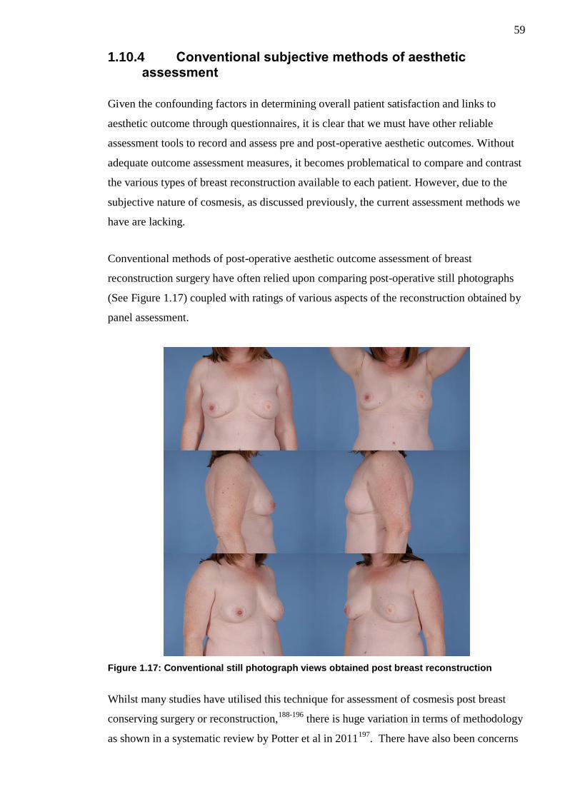
59
1.10.4 Conventional subjective methods of aesthetic assessment
Given the confounding factors in determining overall patient satisfaction and links to
aesthetic outcome through questionnaires, it is clear that we must have other reliable
assessment tools to record and assess pre and post-operative aesthetic outcomes. Without
adequate outcome assessment measures, it becomes problematical to compare and contrast
the various types of breast reconstruction available to each patient. However, due to the
subjective nature of cosmesis, as discussed previously, the current assessment methods we
have are lacking.
Conventional methods of post-operative aesthetic outcome assessment of breast
reconstruction surgery have often relied upon comparing post-operative still photographs
(See Figure 1.17) coupled with ratings of various aspects of the reconstruction obtained by
panel assessment.
Figure 1.17: Conventional still photograph views obtained post breast reconstruction
Whilst many studies have utilised this technique for assessment of cosmesis post breast
conserving surgery or reconstruction,188-196
there is huge variation in terms of methodology
as shown in a systematic review by Potter et al in 2011197
. There have also been concerns
60
that the methodology employed in these studies lack precision and are difficult to
reproduce189
.
Furthermore many of the researchers involved in the aforementioned studies will
statistically analyse the results obtained from panel ratings to show the degree of inter-rater
reliability between the members of the assessment panel189,190,198-200
. A greater degree of
inter-rater agreement between panel members is believed to relate to more scientifically
robust results.
Whilst still photographs are able to convey a certain degree of information to the panel,
they are inherently limited by the fact that they are two-dimensional in nature, offer no
demonstration of breast mobility and are subject to great panel dispute. Breast mobility is
of particular interest in terms of autologous tissue transfer, as it is believed that autologous
tissue reconstructions move much more like a natural breast, in comparison to implant
based reconstruction and this may explain the trend towards patients reporting higher
levels of aesthetic satisfaction; however this cannot be visualised on static photographs.
1.10.5 Novel objective methods of aesthetic assessment
In an effort to improve upon the flaws described above, other more objective assessment
methods have been described, such as the use of computer software designed to take
objective measurements from two dimensional digital photographs with subsequent
computer analysis of various indices linked to symmetry198,199,201
.
This technique has been further improved upon through the use of three-dimensional
imaging systems; allowing the capture of a greater amount of information202,203
. The
objective data obtained from three-dimensional imaging system shows promise in being
more accurate than traditional subjective assessments200
. However, these complex systems
are all very expensive, require vast user expertise in terms of set-up and analysis and are
not available in the majority of plastic surgery units.
1.11 Summary
In summary, breast reconstruction using free abdominal tissue, such as the DIEP flap,
offers many advantages to the patient and appears to be linked to high satisfaction in terms
of cosmesis, despite inadequate techniques of post-operative aesthetic outcome assessment.
Unfortunately, it is evident that problems can occur with the DIEP flap particularly with

61
regards to its vascular supply and venous congestion leading to potential compromise of
the flap. Zone IV of the flap is the most liable to suffer these problems and as such is
commonly discarded in an effort to prevent flap related complications but these can still
occur regardless. In an effort to allow the harvest of larger flaps or to salvage compromised
flaps, strategies in the form of vascular augmentation procedures have been described, but
there is little research into the effect that these procedures have on flap perfusion. Further
research into the effects on perfusion of these procedures may allow the harvest of larger
DIEP flaps with a better vascular supply.

62
Chapter 2: Outline of Completed Studies
Use of abdominal flaps, including the free DIEP flap is well established in reconstruction
of the breast following cancer. However, there are issues identified in terms of post-
operative outcome assessment of such reconstructions and the problems associated with
Zone IV DIEP flap perfusion.
As such the following studies have been undertaken:
2.1 The effect of vascular augmentation on DIEP flap Zone IV perfusion utilising the contralateral SIEA/SIEV
The aim of this study was to assess in-vivo the effects of vascular augmentation on DIEP
flap Zone IV perfusion by augmenting the flap using the contralateral SIEA, SIEV or both
in combination.
2.2 The effects of vascular augmentation on abdominal flap Zone I / IV perfusion and main pedicle arterial blood flow in an experimental animal model
The aim of this experimental study was to investigate the effects of vascular augmentation
upon flap Zone I / Zone IV perfusion and also the effect this intervention has upon the
main pedicle arterial blood flow in a rat abdominal flap.
2.3 The use of real-time digital video in the assessment of post-operative outcomes of breast reconstruction
The aim of this study was to assess whether standardised real-time digital video footage
was a valid assessment tool in assessing post-operative outcomes and to compare its use
against standardised static photography.
63
Chapter 3: Materials and Methods
3.1 Materials and Methods for Chapter 4
3.1.1 Ethical Approval
Ethical approval for this study was sought and granted by the West of Scotland Research
Ethics Committee (REC 4 - 11/WS/0117).
3.1.2 Statistical Design
This was a pilot study. Determining sample size for a pilot study is known to be difficult
and the literature concerning this issue is limited. Van Belle204
and Julious205
suggested the
“rule of 12” for pilots studies as they found that increasing a sample size to 12 participants
had a large effect upon the confidence intervals of observed data; but increasing the sample
size further did not. A sample size of 12 is also considered practical for small scale studies
whilst still being able to provide valuable preliminary information206
. This was discussed
with a medical statistician and it was felt that a sample size of 12 would feasibly provide
enough data to drive a statistically valid study or indeed provide data to generate power
calculations for further larger scale studies in this area.
3.1.3 Patient Selection
Patients due to undergo breast reconstruction with free unilateral DIEP flaps by Mr IR
Mackay were identified from the surgical waiting list at Canniesburn Plastic Surgery Unit,
Glasgow Royal Infirmary.
3.1.3.1 Inclusion Criteria
1. Female breast reconstruction patients
2. Age between 18-70 years
3. Due to undergo either immediate or delayed unilateral free DIEP flap breast
reconstruction
3.1.3.2 Exclusion Criteria
1. Bilateral reconstructions

64
2. History of hyperthyroidism or thyroid adenoma (ICG dye contraindicated in
such patients)
3. History of allergic reaction to iodine or ICG dye
4. ASA grade ≥ 3
5. Patients with abdominal scarring
3.1.3.3 Consent
Potential participants were approached with an information sheet about the study. Written
informed consent was obtained from all patients.
3.1.4 Clinical assessment
Patient information including demographics, past medical history, drug history and social
history were collected, as per standard pre-operative breast reconstruction surgery, during
each patients’ pre-operative assessment and this information stored in the patients notes.
3.1.5 Randomisation Process
In order to assess the contribution of each individual component of the superficial vascular
system on the perfusion of Zone IV four different intervention sequences were required.
These sequences were as follows
Both SIEA and SIEV clamped (traditional flap)
Both SIEA and SIEV unclamped (arterial and venous augmentation)
SIEA unclamped and SIEV clamped (arterial augmentation)
SIEA clamped and SIEV unclamped (venous augmentation)
The order in which each intervention sequence was carried out was randomised via an
independent internet based randomisation service; utilising true randomness generation via
atmospheric noise207
, for every patient prior to the commencement of their operative
procedure.

65
3.1.6 Environmental Conditions
All procedures/measurements were carried out in the same theatre under the same
controlled environmental conditions.
Previous studies with regards to measurement of cutaneous blood flow using Laser
Doppler suggest that capillary blood flow within skin is stable when environmental
temperatures are between 17-28 degrees Celsius208,209
thus ambient theatre temperature
was set at a level between 25 and 27 degrees Celsius and was recorded prior to and during
the measurement process to ensure that it was kept constantly within this range.
It has been shown that reflected light can interfere with LDI scan results in terms of falsely
high flux readings209
. In order to standardise environmental lighting and reduce possible
interference from reflected light sources during the scanning process the main operating
theatre lights were turned off and the internal lighting dimmed to lowest possible level.
Windows were temporarily occluded to block any other external sources of light from
entering the theatre.
During the scanning capture period of the study all entrances to the theatre were closed and
signs placed to prevent intrusion and interruption to the study.
3.1.7 Laser Doppler Imaging
3.1.7.1 Laser Doppler Imaging Machine Specifications
A MoorLDI2-IR laser Doppler blood flow imaging system (Moor Instruments, Axminster,
Devon, UK) owned by the Canniesburn Research Trust was used during the human study.
The device is portable, based upon a mobile stand and consists of an imaging head,
monitor and computer. The imaging head is linked to an articulated arm allowing easy
positioning over the study area; containing an infra-red laser diode operating at 785nm
optical capture device and also a digital video/photo capture device which can display
images in real time. The central computer contains the software necessary to capture,
process and then store the LDI images for each patient study. The monitor allows real-time
viewing of the digital video feed intra-operatively and to review the captured LDI images
post-operatively. (See Figure 3.1)
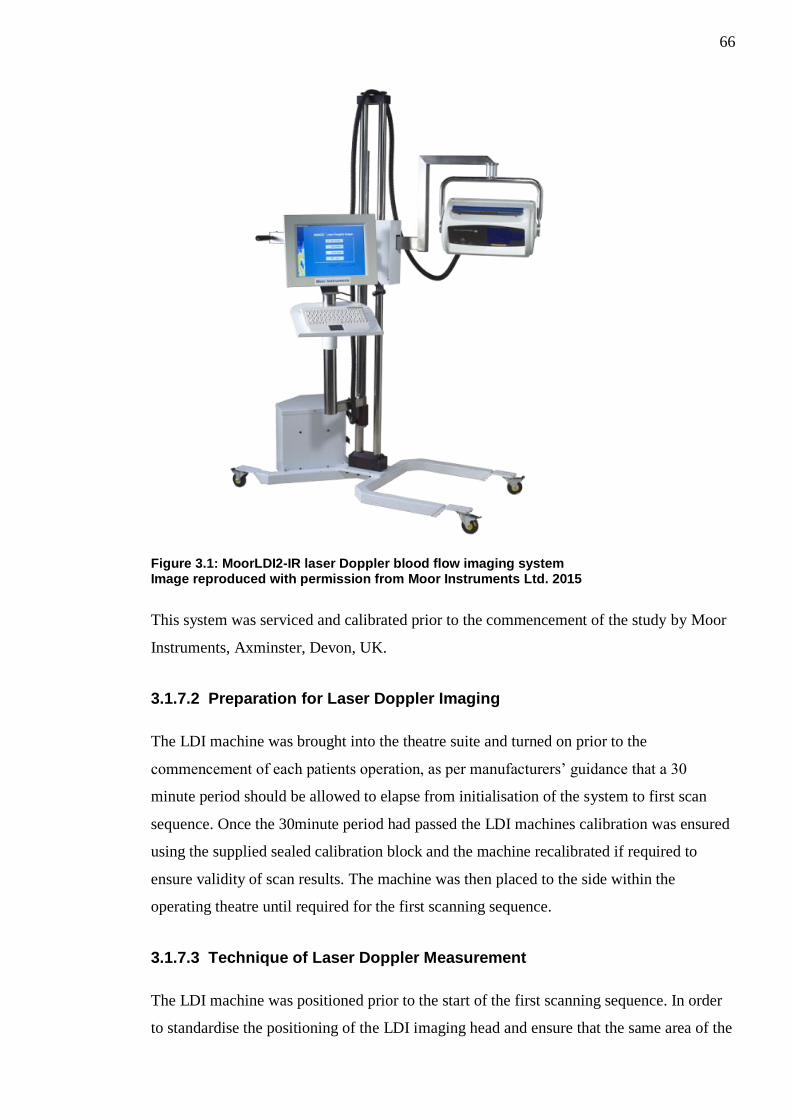
66
Figure 3.1: MoorLDI2-IR laser Doppler blood flow imaging system Image reproduced with permission from Moor Instruments Ltd. 2015
This system was serviced and calibrated prior to the commencement of the study by Moor
Instruments, Axminster, Devon, UK.
3.1.7.2 Preparation for Laser Doppler Imaging
The LDI machine was brought into the theatre suite and turned on prior to the
commencement of each patients operation, as per manufacturers’ guidance that a 30
minute period should be allowed to elapse from initialisation of the system to first scan
sequence. Once the 30minute period had passed the LDI machines calibration was ensured
using the supplied sealed calibration block and the machine recalibrated if required to
ensure validity of scan results. The machine was then placed to the side within the
operating theatre until required for the first scanning sequence.
3.1.7.3 Technique of Laser Doppler Measurement
The LDI machine was positioned prior to the start of the first scanning sequence. In order
to standardise the positioning of the LDI imaging head and ensure that the same area of the
67
flap was scanned in each subsequent scanning sequence the mobile base of the LDI
machine was locked in position and its articulating arm set at the furthermost point with
the area of the flap to be scanned within the imaging window. The imaging head height
was set at 30cm from the flap and this position locked. The mobile base was not moved
between individual scanning sequences and only the articulating arm was fully retracted
and fully extended between scanning sequences.
Moor BDA version 5.3 software was used to acquire images due to its ease of use, greater
reliability and consistency. Scanning parameters were set as medium scan type (resolution
of 64) on a large vertical rectangle at 4milliseconds/pixel. Each LDI scanning sequence
took exactly two minutes. Scanning sequences for each patient in the study were stored on
the hard drive for subsequent analysis.
3.1.8 ICG Angiography
3.1.8.1 ICG Angiography Machine Specifications
A SPY® intra-operative fluorescence vascular angiography system developed and
manufactured by Novadaq® (Novadaq Technology Inc., Mississauga, Ontario, Canada)
was used in the human study. This device was supplied to our plastic surgery unit on loan
by CardioLogic® (CardioLogic Ltd, Yorkshire, United Kingdom) the UK distributor of the
Novadaq SPY imaging technology. (See Figure 3.2)

68
Figure 3.2: SPY® intraoperative imaging system
The device is portable and easily movable around the theatre suite. It consists of an
imaging head, monitor, computer and optical storage drive. The imaging head is linked to
an articulated arm allowing easy positioning over the study area, containing both a laser
operating at 805nm (to cause fluorescence of the ICG dye) and an optical capture device
which can record in real time the resultant fluorescence. The central computer contains the
software necessary to capture; process and then store the image sequences on the optical
storage drive for each patient study. The monitor allows real-time viewing of the
fluorescence intra-operatively and to review the captured sequences.
This system was serviced and calibrated prior to the commencement of the study.
3.1.8.2 Preparation for ICG Angiography
The SPY® imaging system was brought into the theatre suite and turned on prior to the
commencement of each patients operation. The machine was then placed to the side within
the operating theatre until required for the first ICG angiography scanning sequence.

69
The ICG dye used in this study was ICG-Pulsion® manufactured by Pulsion Medical
Systems (PULSION Medical UK, Middlesex, United Kingdom). This comes in a sterile
vial containing a lyophilised form with approximately 25mg of active ICG and sodium
iodide as a preservative. This was reconstituted with 5ml of sterile water prior to yield a
constitution of 5mg/ml.
3.1.8.3 Technique of Indocyanine Green Angiography Measurement
The SPY® imaging system was positioned prior to the start of the first scanning sequence.
In order to standardise the positioning of the SPY® imaging head and ensure that the same
area of the flap was scanned in each subsequent scanning sequence the mobile base of the
SPY® machine was locked in position and its articulating arm set at the furthermost point
with the area of the flap to be scanned within the imaging window. The imaging head
height was set at 40cm from the flap and this position locked. The mobile base was not
moved between individual scanning sequences and only the articulating arm rotated
between scanning sequences.
2ml of reconstituted ICG dye (5mg/ml) (cf. 3.1.8.2) was injected into a peripheral access
line immediately followed by a fluid bolus of 20mls of sterile water. 20 seconds was
allowed to elapse to allow the dye to fully enter the circulation (as per the manufacturers’
guidelines) and then the scan of flap skin paddle using the SPY® intraoperative imaging
system was commenced. Immediately following the scan of the flap skin paddle a
subsequent scan was performed upon the fat component of the flap to assess fat perfusion.
Each scanning sequence lasted 38 seconds and sequences were stored on hard drive for
subsequent analysis.
Between each change in variable to be assessed and subsequent scanning sequence; a time
interval of 10 minutes was allowed to pass in order for the dye to be fully eliminated from
the circulation as was the protocol in a previous study carried out within our unit168
and
shown in other published work210
.
2ml of ICG dye (5mg/ml) was required for each combined skin/fat scanning sequence and
a total of 40 mg was used upon each study participant.
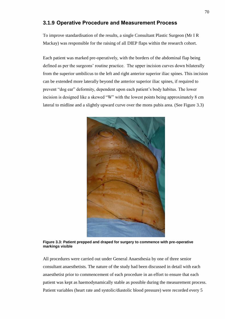
70
3.1.9 Operative Procedure and Measurement Process
To improve standardisation of the results, a single Consultant Plastic Surgeon (Mr I R
Mackay) was responsible for the raising of all DIEP flaps within the research cohort.
Each patient was marked pre-operatively, with the borders of the abdominal flap being
defined as per the surgeons’ routine practice. The upper incision curves down bilaterally
from the superior umbilicus to the left and right anterior superior iliac spines. This incision
can be extended more laterally beyond the anterior superior iliac spines, if required to
prevent “dog ear” deformity, dependent upon each patient’s body habitus. The lower
incision is designed like a skewed “W” with the lowest points being approximately 8 cm
lateral to midline and a slightly upward curve over the mons pubis area. (See Figure 3.3)
Figure 3.3: Patient prepped and draped for surgery to commence with pre-operative markings visible
All procedures were carried out under General Anaesthesia by one of three senior
consultant anaesthetists. The nature of the study had been discussed in detail with each
anaesthetist prior to commencement of each procedure in an effort to ensure that each
patient was kept as haemodynamically stable as possible during the measurement process.
Patient variables (heart rate and systolic/diastolic blood pressure) were recorded every 5

71
minutes throughout the operation. Patient core temperature was also recorded every 15
minutes through the use of a nasal temperature probe. Maintenance of patient temperature
was aided by the use of Bair Hugger™ blanket covering areas of the patient out-with the
operative field.
Raising of each DIEP flap was carried out as standard from lateral to medially bilaterally;
however considerable additional care was taken to identify and preserve the superficial
vascular system (SIEA/SIEV), initially on both sides. (See Figure 3.4)
Figure 3.4: Right SIEA (white vessel sloop) and SIEV (blue vessel sloop) dissected free
Concomitantly the patient underwent mastectomy (unless delayed) by one of two
Consultant Breast Surgeons. The medial 4th
costochondral cartilage was removed and the
underlying internal mammary artery (IMA) and internal mammary vein (IMV) prepared to
act as recipient vessels for microvascular transfer.
After deciding upon which side to base the flap (dependent upon the adequacy of the
perforating blood vessels in terms of size, dissection required and pulsatility); the
perforator(s) were dissected to their origin from the main pedicle (DIEA/DIEV). (See
Figure 3.5)

72
Figure 3.5: Patient 12 in study showing DIEP flap based on a left large medial row and small lateral row perforator with an intramuscular course The preserved motor nerve can be seen crossing over the top of the pedicle
The ipsilateral superficial vascular system to the main pedicle was divided, leaving the
contralateral superficial vascular system intact.
The DIEP flap was completely islanded on only the perforators supplied from the main
pedicle (DIEA/DIEV) and contralateral superficial vascular system (SIEV+/-SIEA).
The flap was divided into the classical Hartrampf’s zones of perfusion (I-IV) and these
areas marked. The flap was then temporarily secured in its anatomical position with several
silk sutures on the side not being assessed (i.e. contralateral side to zone IV), as shown in
Figure 3.6.

73
Figure 3.6: Left DIEP flap divided into Zone I-IV and secured in place prior to scanning.
Single arterial and venous Acland clamps (3A and 3V respectively) were used to occlude
the SIEA, SIEV or both as per the randomised intervention sequence (cf. 3.1.5). Following
each clamping/unclamping intervention a period of 5mintues was allowed to elapse prior to
allow perfusion within the flap to stabilise and reactive hyperaemia to settle211
.
Perfusion measurements using LDI (cf. 3.1.7.3) and ICG angiography (cf. 3.1.8.3) were
obtained.
Each measurement sequence was carried out as per the flowchart diagram shown in Figure
3.7.
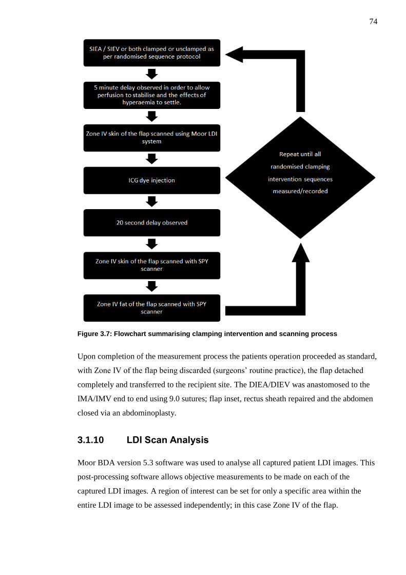
74
Figure 3.7: Flowchart summarising clamping intervention and scanning process
Upon completion of the measurement process the patients operation proceeded as standard,
with Zone IV of the flap being discarded (surgeons’ routine practice), the flap detached
completely and transferred to the recipient site. The DIEA/DIEV was anastomosed to the
IMA/IMV end to end using 9.0 sutures; flap inset, rectus sheath repaired and the abdomen
closed via an abdominoplasty.
3.1.10 LDI Scan Analysis
Moor BDA version 5.3 software was used to analyse all captured patient LDI images. This
post-processing software allows objective measurements to be made on each of the
captured LDI images. A region of interest can be set for only a specific area within the
entire LDI image to be assessed independently; in this case Zone IV of the flap.
75
In order to ensure that the same region of interest was set for each patients flap, between
the varying scan sequences, the region of interest was always measured as the area
encompassing 1cm from the flap peripheral margins to 1cm within the marked Zone IV
border. By measuring 1cm from the flap periphery this also helped to reduce the artefact
created by the slight curvature of the cut edges which can influence light reflection and
lead to inaccurate flux readings209
.
Median flux values of Zone IV perfusion values for each patient were obtained. Median
LDI flux values were used as previous published work by Tollan et al assessing similar
aspects of DIEP flap perfusion has suggested that median LDI flux values give more
accurate results212
.
3.1.11 ICG Scan Analysis
Captured SPY imaging sequences were analysed via SPY-Q analysis toolkit software. This
post-processing software allows objective measurements to be made on each of the
captured study sequences. A region of interest can be set for the area to be reviewed within
the image sequence and baseline fluorescence intensity for this area can be calculated for
the duration of the capture sequence. The baseline fluorescence intensity can then be used
for quantitative comparisons between imaging sequences.
In order to ensure that the same region of interest was set for each patients flap, between
the varying scan sequences, the same process was utilised as for LDI Scan analysis (cf.
3.1.10) with the region measured at 1cm from the flap periphery.
Mean Zone IV skin and fat perfusion values for each patients scanned sequences were
obtained.
3.1.12 Statistical Analysis
All results were analysed using Minitab version 16 (Minitab Inc., State College, PA).
Continuous data was assessed for normality using the Anderson-Darling test of Normality.
A repeated measures analysis of variance (ANOVA) test was used to assess for statistically
significant differences between each of the clamping/vascular augmentation interventions.
Where p<0.05 in the repeated measures ANOVA test the Bonferroni correction method

76
was used to assess for pairwise differences between each vascular augmentation
intervention and the control group (traditional flap).
Since it was well established that the SIEA may be absent in up to 13-35% of patients65-67
it was proposed that should the SIEA be absent in any of our study cohort that the SIEV
clamping and unclamping still be utilised for analysis. In such cases when the SIEV was
clamped the result obtained was placed in the “Both Clamped” and when the SIEV was
unclamped the result was placed in the “SIEA Clamped / SIEV Unclamped” category to
allow for correlation. Separate sub-analysis excluding those patients where the SIEA was
not present was undertaken to ensure accuracy of the results.

77
3.2 Materials and Methods for Chapter 5
3.2.1 Ethical Approval
This study was approved by the University of Glasgow Ethical Review Panel. A personal
investigator licence (60/12807) and project licence (60/4415) under the terms and
conditions of the Animals (Scientific Procedures) Act 1986, was granted by the UK
Government Home Office.
3.2.2 Statistical Design
As this was a pilot study measuring the effects on perfusion and flow of vascular
augmentation of rat abdominal flaps there was not sufficient data in the literature upon
which to base a power calculation.
The Home Office and The National Centre for the Replacement, Refinement and
Reduction of Animals in Research (NC3Rs), a UK based scientific organisation dedicated
to reducing the number of animals used in research, suggest the following resource
equation when deciding upon animal numbers to be used in small non-routine pilot studies
such as our own.
E = N (number of animals per treatment x number of treatments) - T (number of
treatments)213
.
They state that E (the sample size) should be a number between 10 and 20, to use the
minimal number of animals possible whilst providing scientifically valid results.
10 animals were proposed to be used in this study comprising of two treatment groups
(traditional vs vascular augmented) and thus the following resource equation was made:
E = ((10 x 2) – (2)) = 18
This fell within the recommended sample size of 10-20 as stated above. However the
resource equation wasn’t entirely applicable to our study as the above equation considers
the number of treatment arms to require two separate animal cohorts. In our study we were
proposing to perform each treatment arm upon the same abdominal flap of a single animal
using the clamping intervention as described above rather than requiring a separate cohort
of animals. As such rather than requiring 20 animals (10 in each cohort) to perform our
78
research upon we would only require 10 overall. After discussion with the Veterinary
Surgeon representing the Biological Research Division, Veterinary Research Facility,
University of Glasgow he suggested the addition of a further 2 animals to our proposed
cohort of 10 to account for any unexpected complications or mortalities secondary to
anaesthesia or procedure during the experiment.
Thus 12 animals were proposed to be utilised in this experiment and the ethical review
panel and Home Office were satisfied that this adequately reduced the number of animals
required whilst still providing scientifically valid results.
3.2.3 Animals
Male out-bred Sprague Dawley rats were chosen to be used for this research study. This
decision was made following advisement from the Veterinary surgeon from the Biological
Research Division, Veterinary Research Facility, University of Glasgow.
3.2.4 Anaesthesia and Peri-operative care
All animals in this study had the same anaesthetic protocol devised by the named
Veterinary surgeon for the project. Anaesthetic induction was carried out by the named
Veterinary Surgeon and maintenance of their anaesthesia and peri-operative care provided
by specialist animal technicians under his direct supervision.
Animals were weighed pre-operatively; results recorded and their anaesthesia requirements
calculated. Induction was carried out via administration of gaseous Isofluorane in an
animal containment box combined with further intra-peritoneal injection of Inactin®
(thiobutylbarbitole). Following induction all animals received an additional intraperitoneal
injection of atropine to reduce secretions.
Maintenance inhalational anaesthesia (N2O/Isoflourane/O2) was provided to each animal
via voluntary respiration through the use of a nasal cone secured to each animals’ snout.
Each animal in the study had their heart rate and oxygen saturations continuously
monitored via the use of a Nonin 8500AV pulse oximeter probe (Nonin Medical Inc.,
Plymouth, MN, USA) attached to a hind limb.
79
Each animals’ temperature was maintained through the use of an ambient heat source
situated in proximity to the animal. Core temperature was monitored throughout the
procedure through the use of a rectal probe and the heat source moved as necessary to
maintain an adequate temperature between 37-38°C. The rectal probe temperature monitor
was also connected via analogue output to a Powerlab® 400 System to allow continuous
capture and recording of temperature data throughout the measurement period.
3.2.5 Randomisation Process
The side upon which to base the flap and the order of scanning (traditional or vascular
augmented) was randomised via an independent internet based randomisation service207
.
3.2.6 Environmental Conditions
All procedures were carried out in the same room within the same research facility with
ambient temperature controlled between 21-24.5°C.
3.2.7 Laser Doppler Flowmetry
3.2.7.1 Laser Doppler Flowmetry Machine Specifications
A Moor VMS-LDF2 laser Doppler flowmetry system (Moor Instruments, Axminster,
Devon, UK) obtained via loan from Moor Instruments to the Canniesburn Research Trust
was used during the animal study. The device is small and portable, consisting of a central
base unit containing a 785nm diode laser and two input/output channels for the attachment
of optical probes. The base unit has its own digital display on the face panel but also has an
additional analogue output connection. Optical probes supplied with the unit consist of a
probe head (to be attached to the target area of tissue), optical cable and a probe tail which
can be inserted into the base unit. (See Figure 3.8)
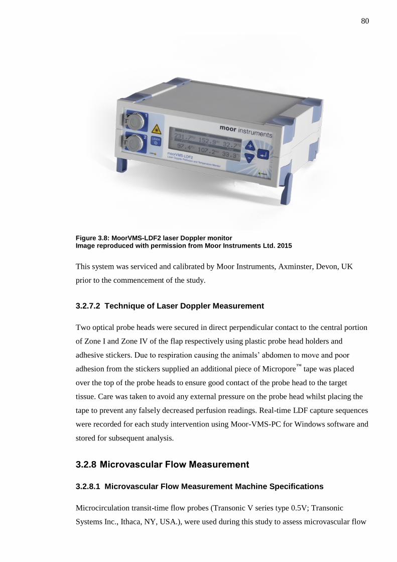
80
Figure 3.8: MoorVMS-LDF2 laser Doppler monitor Image reproduced with permission from Moor Instruments Ltd. 2015
This system was serviced and calibrated by Moor Instruments, Axminster, Devon, UK
prior to the commencement of the study.
3.2.7.2 Technique of Laser Doppler Measurement
Two optical probe heads were secured in direct perpendicular contact to the central portion
of Zone I and Zone IV of the flap respectively using plastic probe head holders and
adhesive stickers. Due to respiration causing the animals’ abdomen to move and poor
adhesion from the stickers supplied an additional piece of Micropore™
tape was placed
over the top of the probe heads to ensure good contact of the probe head to the target
tissue. Care was taken to avoid any external pressure on the probe head whilst placing the
tape to prevent any falsely decreased perfusion readings. Real-time LDF capture sequences
were recorded for each study intervention using Moor-VMS-PC for Windows software and
stored for subsequent analysis.
3.2.8 Microvascular Flow Measurement
3.2.8.1 Microvascular Flow Measurement Machine Specifications
Microcirculation transit-time flow probes (Transonic V series type 0.5V; Transonic
Systems Inc., Ithaca, NY, USA.), were used during this study to assess microvascular flow

81
through the main pedicle DSEA. These probes are designed to be able to assess flow
within vessels of between 0.25-0.5mm in outer diameter, are specifically calibrated for
blood temperature of approximately 37°C and can detect flow rates from 0-50ml/min. The
probes operate at an ultrasound frequency of 7.2Hz, can detect flow rate changes of
0.05ml/min and have a relative accuracy of ±3%. Probes had been calibrated for use in a
study performed the previous year.
Probes consist of a handle (within which runs the cabling to connect to an analogue input)
connected to a probe body and reflector. The space between the probe body and reflector
create a natural lumen also known as the ultrasonic window. (See Figure 3.9)
Figure 3.9: Microcirculation flow probe
Two transducers present on either side of the probe body simultaneously convert electrical
energy to ultrasonic energy and ultrasonic energy back to electrical energy. The ultrasonic
signals are passed back and forth through the ultrasonic window, this is shown in Figure
3.10.

82
Figure 3.10: Mechanism through which the flow probe operates Image reproduced with permission from Transonic System Inc. (2015)
The time taken for these signals to reach the opposite transducer can be detected in terms
of changes in the electrical signals sent and received using a flowmeter.
Flow probes were attached to a transit-time ultrasonic flowmeter (T204, Transonic
Systems Inc.) which converts the analogue signal received from the flow probe into an
estimation of mean flow in mL/min and this is displayed on the digital display on the face
panel of the machine. Given the small size of the vessels studied and microvascular probes
used, the flowmeter was set on low-flow setting which allows a more accurate assessment
of intravascular flow within small vessels by recording separate flow measurements every
0.0025 seconds. This data was subsequently digitised through an analogue output
connection to a Powerlab® 400 System (AD Instruments Pty Ltd.). The Powerlab® 400
System was in turn connected via USB cable to a laptop PC running Chart V5.56 for
Windows (AD Instruments Pty Ltd.) software allowing continuous capture of flow data.
3.2.8.2 Preparation for intra-vascular flow measurement
Flow probes were soaked in sterile saline (maintained at a temperature of 37°C) for at least
ten minutes prior to the measurement process commencing. This was in line with
manufacturer recommendations to eliminate a random-drift in zero offset.
3.2.8.3 Technique of intra-vascular flow measurement
Flow probes were sited within the incised rectus sheath and held firmly in a stable position
using an external stand and microvascular clamp. The DSEA was placed within the lumen

83
of the probe and drops of sterile saline (maintained at a temperature of 37°C) were used to
submerge the area and act as an acoustic couplant. A five minute interval was observed
after the placing of the microvascular flow probe prior to obtaining any measurements to
allow for stabilisation of the vessel and flow following positioning within the lumen of the
probe.
Continuous capture and recording of flow data was made using the Powerlab® 400 System
/ PC interface (cf. 3.2.8.1).
3.2.9 Experimental Procedure
3.2.9.1 Flap Raising
To ensure standardisation of the results obtained all animal flaps were raised in the same
manner by the same surgeon (thesis author). Following anaesthetic induction (cf. 3.2.4)
each animal’s abdomen was depilated using a mechanical razor.
Animals were positioned supine upon a dissecting board and their limbs extended. The
periphery of the abdominal flap was marked and the flap subdivided into four Zones to
mimic Hartrampf’s Zone of perfusion (cf. 1.6.4) (See Figure 3.11)
Figure 3.11: Anaesthetised Sprague Dawley rat in supine position with abdominal flap marked
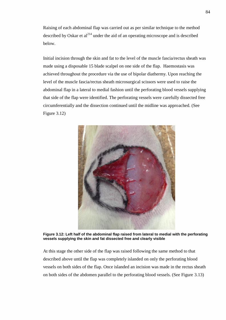
84
Raising of each abdominal flap was carried out as per similar technique to the method
described by Oskar et al214
under the aid of an operating microscope and is described
below.
Initial incision through the skin and fat to the level of the muscle fascia/rectus sheath was
made using a disposable 15 blade scalpel on one side of the flap. Haemostasis was
achieved throughout the procedure via the use of bipolar diathermy. Upon reaching the
level of the muscle fascia/rectus sheath microsurgical scissors were used to raise the
abdominal flap in a lateral to medial fashion until the perforating blood vessels supplying
that side of the flap were identified. The perforating vessels were carefully dissected free
circumferentially and the dissection continued until the midline was approached. (See
Figure 3.12)
Figure 3.12: Left half of the abdominal flap raised from lateral to medial with the perforating vessels supplying the skin and fat dissected free and clearly visible
At this stage the other side of the flap was raised following the same method to that
described above until the flap was completely islanded on only the perforating blood
vessels on both sides of the flap. Once islanded an incision was made in the rectus sheath
on both sides of the abdomen parallel to the perforating blood vessels. (See Figure 3.13)

85
Figure 3.13: Abdominal flap completely islanded on perforating blood vessels with the bilateral incisions through the cranial rectus sheath visibile
Once the main deep superior epigastric vascular pedicle was identified cranially bilaterally
it was dissected in a cranial to caudal direction taking extreme care to preserve the
perforating blood vessels. Dependent upon the results of flap randomisation (cf.3.2.5), on
the side which the flap was to be based the cranial most perforating blood vessels
supplying that side was identified and all caudal perforating vessels cauterised. (See Figure
3.14)
Figure 3.14: Flap based on right side with the solitary cranial perforator clearly visible All caudal perforators on this side have been cauterised

86
The solitary perforating blood vessels were then carefully dissected through the rectus
sheath (taking a small cuff of rectus sheath and rectus muscle to preserve the integrity of
the extremely small perforators) to their point of origin from the main deep superior
epigastric pedicle. Caudal to the origin of these perforating vessels the deep superior
epigastric artery (DSEA) and vein (DSEV) were ligated using 10.0 Ethilon sutures.
On the contralateral side of the flap a similar process was undertaken although the most
caudal perforator was selected and dissected completely free to its origin and all cranial
perforating blood vessels cauterised above the rectus sheath and ligated at their respective
origins from the DSEA and DSEV using 11.0 Ethilon sutures. (See Figure 3.15)
Figure 3.15: Dissection of the caudal most perforator on the contralateral side of the flap
The DSEA and DSEV were then ligated caudal to the dissected caudal-most perforating
vessels using 10.0 Ethilon sutures. At the cranial-most point where the DSEA and DSEV
are emerging from below the rib-cage on this side of the flap the DSEA and DSEV were
dissected free.
In summary at this stage of completed flap dissection the flap is obtaining its vascular
supply from a pedicle containing the cranial most perforating artery and vein from the
DSEA and DSEV (main pedicle) on one side of the flap and the contralateral DSEA and
DSEV pedicle (augmentation pedicle) containing only the caudal most perforating artery
and vein.

87
A transit-time ultrasound flow probe (Model 0.5V, Transonic Systems Inc.) was then
inserted through the incision in the rectus sheath and the main pedicle DSEA supplying the
flap was placed within the flow probe (cf 3.2.8.3). The flow probe was secured externally
in position using a clamp attached to a stand.
The flap was then sutured back into its original position taking care to avoid any tension
using 5.0 Ethilon sutures. (See Figure 3.16)
Figure 3.16: Flap completely raised and secured in anatomical position The transit-time ultrasound flow probe placed around the right DSEA can be observed held in position with a clamp
MoorVMS-LDF2 laser Doppler monitor optical probes were then attached to Zone I and
Zone IV of the flap respectively (cf. 3.2.7.2).
The set-up of the multiple machines used in this experiment (MoorVMS-LDF2 laser
Doppler monitor; T204 flowmeter, Powerlab® 400 system) is shown in Figure 3.17.

88
Figure 3.17: Equipment set-up in animal experiment model
If the first scanning sequence had been randomised to assess the traditional flap initially
then the contralateral DSEA/DSEV pedicle was occluded using a removable Acland B1-V
microvascular clamp.
3.2.9.2 Measurement Process
Upon completion of flap raising (irrespective of clamped or non-clamped pedicle) there
was a five minute interval observed prior to the commencement of the measurement
process to allow the flap to stabilise and the effects of any reactive hyperaemia to
settle168,211
.
Prior to each measurement sequence animal heart rate and oxygen saturation were
recorded.
LDF perfusion readings obtained through the optical probes attached to Zone I and Zone
IV of the flap were recorded for a period of one minute (cf. 3.2.7.2) and the results stored
for subsequent analysis.
Concurrent flow rate measurements through the main ipsilateral SEA were obtained for the
same one minute period (cf. 3.2.8.3) and recorded in Chart V5.56 for Windows for
subsequent analysis.

89
Once these measurements were complete the clamp was either placed on or removed from
the contralateral DSEA and DSEV and a further 5 minute interval was observed to again
allow for reactive hyperaemia to settle.
At the end of the measurement process all animals were humanely terminated via a method
approved under schedule 1 to the Animals (Scientific Procedures) Act 1986.
3.2.10 Laser Doppler Flowmetry Analysis
Moor-VMS-PC for Windows was used to analyse the data obtained via the MoorVMS-
LDF2 laser Doppler monitor optical probes. Subsequent analysis of captured sequences
utilising this software allow for the calculation of mean flux results over the entire capture
period.
Mean flux values were obtained from Zone I and Zone IV in the traditional and vascular
augmented flaps.
3.2.11 Intravascular Flow / Temperature Analysis
LabChart Reader Version 8 (AD Instruments Pty Ltd.) for Microsoft Windows was used to
analyse all data captured by the PowerLab® 400 system. This software allows the user to
analyse and interrogate the digital data generated by the Powerlab® 400 System and its
analogue inputs.
Mean core temperature values for the entire procedure and mean flow rate through the
main pedicle DSEA (for the one minute observation period of the study) were obtained.
3.2.12 Statistical Analysis
All results were analysed using Minitab version 16 (Minitab Inc., State College, PA).
Continuous data was assessed for normality using normal probability plots and an
Anderson-Darling test of Normality. Data was found to be non-normally distributed and as
such non-parametric tests were chosen for statistical analysis.
Wilcoxin Signed Rank tests were used to assess for any statistically significant differences
in the results obtained from the traditional flaps and those obtained for the vascular

90
augmented flaps. Comparisons were made between Zone I and Zone IV perfusion; flow
rate through main DSEA and pulsatility index pre and post vascular augmentation.

91
3.3 Materials and Methods for Chapter 6
3.3.1 Ethical Approval
Ethical approval for this study was sought and granted by the West of Scotland Research
Ethics Committee (REC 1 – 12/WS/0082).
3.3.2 Statistical Design
A medical statistician was recruited to the research team to provide their input for this
study in terms of sample size and analysis of the results.
A formal power calculation to judge the required sample size was not possible as this was a
pilot study and as such there were no available studies on the topic upon which to obtain a
reasonable estimate of the standard deviations required for a calculation.
Traditional studies utilising inter-rater agreement between responses have focussed upon
assessing kappa scores (cf. 1.10.4). Simple kappa scores can only recognise absolute
agreement or disagreement between raters and do not make any account of the varying
levels of disagreement. A modification to the simple kappa score is that of weighted kappa
scores; these scores measure varying degrees of disagreement by assigning different
“weights” to each of the responses measured. The further apart the responses from each
other the higher the weight assigned; i.e. higher levels of disagreement are associated with
higher weight allocations.
On the statisticians advice utilising the suggestions by Norman and Streiner46
who
indicated that the sample size for weighted kappa would require too many guesses and
invoke a rule of thumb; the minimum number of objects being rated should be more than
2c² (where c is the number of categories).
For our purposes utilising an assessment grading based on four categories we should
ideally have 2x42=32 subjects.
As such it we deemed recruitment of 35 patients to be appropriate for the requirements of
the study.

92
3.3.3 Patient Selection
Participants were recruited from the Canniesburn Plastic Surgery Unit areolar tattooing
clinic. This was to ensure that all oncological, adjuvant and surgical reconstructive
treatments had been completed.
3.3.3.1 Inclusion Criteria
1. Females aged 18 or more years
2. Breast reconstruction patients
3. Greater than six months post breast reconstruction
4. Due to attend for areolar complex tattooing
3.3.3.2 Exclusion Criteria
1. Bilateral reconstructions
2. Unilateral reconstruction less than six months ago
3. Breast reconstructions not specifically carried out following breast cancer
excision
3.3.3.3 Patient Consent
Patients meeting the above criteria were written to with a patient information leaflet
detailing the study in question. Patients who wished to participate in the study were met
prior to their tattooing procedure or tattoo follow-up review and shown the instructional
demonstrational digital video clip to ensure that they were fully informed as to what would
be expected. Written informed consent was obtained and each patient was given a unique
identifiable subject number. Patients were able to withdraw from the study at any time.
3.3.4 Clinical assessment
Information including patient demographics and details upon type of breast reconstruction
surgery were collected.
93
3.3.5 Patient Satisfaction Assessment
Each patient in the study was asked to complete a 22 item Breast Cancer Treatment
Outcomes Scale (BCTOS) questionnaire developed by Stanton et al with regards to their
opinion on their reconstruction215
(See Appendix B). This questionnaire requires the
patient to compare their reconstruction with the non-reconstructed breast and to score on a
simple 1 (no difference) – 4 (large difference) scale for various aspects ranging from
cosmesis to function.
3.3.6 Standard photography
All participants underwent standard breast photography as per current Canniesburn Plastic
Surgery Unit Guidelines. These comprise of the following static photographic views of
both breasts: antero-posterior with hands at sides, antero-posterior with hands raised above
head, right lateral, left lateral, left oblique and right oblique. (See figure). Photographs
were taken by one of two clinical photographers in the same dedicated photography studio
using a Nikon D200® digital single-lens reflex camera. These digital photographs were
transferred from the camera onto computer as JPEG image files.
3.3.7 Video capture
As no standard for digital video capture exists, a novel protocol for digital video capture
was created by Mr A Malyon (Consultant Plastic & Reconstructive Breast Surgeon). This
outlined the instructions for a sequence of movements (incorporating all views obtained by
photography), deemed necessary to allow subjective assessment. (See Figure 3.18)

94
Figure 3.18: Scripted sequence of movements for digital video capture Image reproduced with permission from Elsevier Ltd. (Gilmour et al. 2014)
216
The movements were designed to protect patient anonymity at all stages and to prevent
defining facial shots to be captured during the filming stages.
The services of a professional female model were utilised to perform the above scripted
routine whilst undergoing digital video capture by a cinematographer within a dedicated
studio of the Medical Illustration Department; Glasgow Royal Infirmary.
Narrated position and movement instructions were then added to the video footage to
create an instructional demonstrational digital video clip providing both clear visual and
audio instructions to the viewer.
Following the photography session the patients were moved to a filmography studio and
underwent digital video capture whilst being requested to copy exactly the visual and audio
instructions of the demonstration video which was being played to them concurrently via a
televised feed in their direct view within the studio. All digital video capture was carried
Stand facing camera with
hands on hips
Turn fully to one side, pause then
turn back to centre
Repeat to other side
Turn halfway to one side, pause then turn back
to centre
Repeat to other side
Stand facing camera with hands hands above head
Turn fully to one side, pause then
turn back to centre
Repeat to other side
Turn halfway to one side, pause then turn back
to centre
Repeat to other side
Stand facing camera with hands hands above head
Turn fully to one side and pause
Lower arms to hips and pause
Raise arms above head
Turn fully to other side and
repeat
Stand facing camera with hands above
head
Turn halfway to one side and
pause
Lower arms to hips and pause
Raise arms above head
Turn halfway to other side and
repeat
Stand facing camera with
hands on hips Look up
Tip slowly to one side, pause then return to centre
Repeat to other side
Repeat sequence again
Stand facing camera with
hands on hips
Place chin on chest
Lean forward then lean back
to centre Repeat
Repeat on other side
With hands on hips turn fully
to one side
Turning head away from
camera
Lean forward then lean back
to centre Repeat
Repeat on other side

95
out by a single cinematographer in the same dedicated studio using a Sony PMW-EX1®
digital video camera. The video clips were then cropped using Final Cut Pro© software
(Apple Inc.) and made into Windows® Media Audio/Video files.
3.3.8 Creation of image/video sets
The six digital photography images for each patient in the study were transferred onto a
single Powerpoint slide (Microsoft Powerpoint 2010) to create an image set for each
patient and their unique subject number was placed in the non-visible notes section to
allow later identification. (See Figure 3.19)
Figure 3.19: Example of an image set used in panel assessment presentation

96
Each separate patient slide was then compiled to create a complete Powerpoint
presentation of all the patient photography image sets. The order of these patient slides was
randomised using an online random list generator207
and the heading of each slide named
Image set 1,2,3 and so forth; yet being patient identifiable due to their hidden unique
subject number. The same process was repeated to create a separate Powerpoint
presentation comprised of the patient video sets.
3.3.9 Panel Assessment Process
A panel comprising of seven Plastic Surgeon (six Consultant Plastic Surgeons all with
subspecialist interest in breast reconstruction and one senior onco-plastic breast fellow),
five Consultant General Breast Surgeons and nine non-surgical allied health professionals
was convened.
Each panel member was issued with a Panel Member Instruction sheet welcoming them to
the panel and explaining the assessment process.
The panel members were issued with a simple assessment score sheet in which to record
their views. The footer of each assessment score sheet was numbered with a unique panel
member assessment number in order to ensure that each sheet was unique to each panel
member.
The assessment score sheet asked panel members to record their opinions initially as to
their overall opinion of the reconstruction on a simple 1-4 scale as originally devised by
Harris194
. (See Table 3.1)
Score Rating
1 Excellent - Treated breast nearly identical to untreated breast
2 Good – Treated breast slightly different than untreated breast
3 Fair – Treated breast clearly different from untreated breast, but not seriously distorted
4 Poor – Treated breast seriously distorted
Table 3.1: Breast cosmesis assessment scoring scale (Harris et al. 1979)
194
In addition the panel was also asked to rank their opinion on individual aspects of each
reconstruction in terms of Size, Shape and Elevation (and in the case of the video clips
Mobility) using a similar 1-4 scale as developed by Stanton et al215
. (See Table 3.2)

97
Score Rating
1 No difference between treated and untreated breast and area
2 Slight difference between treated and untreated breast and area
3 Moderate difference between treated and untreated breast and area
4 Large difference between treated and untreated breast and area
Table 3.2: Breast cancer outcomes treatment scale (BCTOS) (Stanton et al. 2001)
215
The panel was then shown each photograph image set (cf. 3.3.8) as part of the Powerpoint
presentation via a projector.
The panel was given approximately 45 seconds to record their opinions upon the static
photograph image sets on the dedicated assessment sheets.
Following this the panel was shown the Powerpoint presentation containing the video clips
(cf. 3.3.8). Panel members were given the duration of the entire video clip to record their
findings; approx. 150 seconds.
Panel members were blinded as to the identity of each patient at all stages. Each panel
member was also asked to provide their opinion on whether they found the still
photographs or video clips more useful/informative in assessing the post-operative
outcome of breast reconstruction.
At the end of the assessment process all panel assessment forms were collected and the
results correlated and analysed.
The assessment process was completed in a single evening lasting approximately 3 hours
and including a 45 minute refreshment break for the assessors.
3.3.10 Statistical Analysis
All results were analysed using Minitab version 16 (Minitab Inc., State College, PA).
Panel inter-rater agreement was calculated using Kendall’s Coefficient of Concordance for
both still photographs and video assessments. Kendall’s Coefficient of Concordance was
chosen due to the ordinal scale based nature of the assessment scores and the fact that this
test allows for the measurement of agreement between multiple raters assessing the same
sample. The test also takes into consideration the association between the rankings
observed.

98
The values obtained range from 0 (no agreement) to 1 (complete agreement) and can be
further interpreted using the guideline developed by Schmidt217
. (See Table 3.3)
Score Level of agreement
0.1 Very weak agreement
0.3 Weak Agreement
0.5 Moderate agreement
0.7 Strong agreement
0.9 Unusually strong agreement
Table 3.3: Guideline allowing interpretation of Kendall's Coefficient of Concordance Scores (Schmidt 1997)
217
Overall median panel photograph and video scores for each patient were compared to the
patient questionnaire self-scores relating to cosmesis (size, shape and elevation) using a
Spearman’s rank correlation test. This test was chosen due to the difference in assessment
scales used by the patient (cf. 3.3.5) and panel (cf. 3.3.9), as it allows the measure of
agreement between two sets of linear data. The levels of agreement between panel and
patient can be interpreted in a similar manner to the scores above.

99
Chapter 4: The effect of vascular augmentation on DIEP flap Zone IV perfusion utilising the contralateral SIEA/SIEV
4.1 Introduction
Despite the growing volume of reported vascular augmentation procedures being
performed in the literature (cf. 1.8.1) the scientific evidence supporting their use is poor.
There are various experimental animal models162-167
suggesting that these techniques lead
to increased flap survivability but there is little in the way of in-vivo research.
The aim of this study was to assess in-vivo the effects of vascular augmentation on DIEP
flap Zone IV perfusion by augmenting the flap utilising components of the contralateral
SIE vascular system (SIEA & SIEV) and to assess whether arterial, venous or combined
augmentation had the greatest effect.
4.2 Methods
DIEP flaps were raised in patients undergoing unilateral breast reconstruction and islanded
on only the perforators supplied from the main pedicle (DIEA/DIEV) and contralateral
superficial vascular system (SIEV+/-SIEA) (cf. 3.1.9). The flap was divided into
Hartrampf’s zones of perfusion (cf. 1.6.4). A randomised clamping sequence of the various
components of the superficial vascular system was undertaken (cf. 3.1.5) and the resultant
effects on Zone IV perfusion measured by LDI (cf. 3.1.7) and ICG angiography (cf. 3.1.8).
4.3 Results
4.3.1 Patients
Twelve consecutive patients due to undergo free unilateral DIEP flap based breast
reconstruction meeting the inclusion/exclusion criteria were identified and recruited to this
study which was performed from 01/02/12 to 14/02/13.
A summary of patient demographics is shown in Table 4.1.

100
Patient Age
(years) ASA
Grade BMI
(kg/m2) Smoking Status
Pre-operative Chemotherapy
Pre-operative Radiotherapy
1 52 1 30 Non Smoker No No
2 42 1 23 Ex-Smoker 2 years prior No
3 39 1 29 Ex-Smoker No No
4 59 2 27 Ex-Smoker Neo-Adjuvant No
5 50 1 26 Non Smoker No No
6 34 2 24 Current Smoker 2 years prior 2 years prior
7 40 2 26 Non Smoker No No
8 33 1 28 Non Smoker No No
9 43 1 23 Non Smoker Neo-Adjuvant No
10 52 1 27 Non Smoker No No
11 54 1 27 Ex-Smoker No 3 years prior
12 53 2 32 Non Smoker No No
Table 4.1: Summary of patient demographics
One total flap loss occurred in Patient 6 of our cohort. The other eleven flaps (92%) healed
uneventfully with no recorded partial flap loss or fat necrosis. The mean number of post-
operative days till discharge of patients in our cohort was 6.8 (range 6-9days).
One patient in our cohort suffered wide-spread metastases of her breast cancer in the post-
operative follow-up period and unfortunately died 1 year post-operatively. All other
patients were disease free at last clinical follow-up review.
The randomised order of clamping sequences for each patient is shown in Table 4.2.
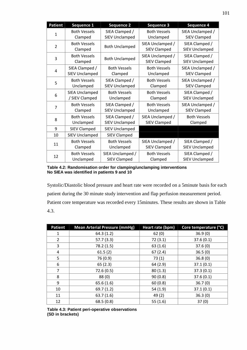
101
Patient Sequence 1 Sequence 2 Sequence 3 Sequence 4
1 Both Vessels
Clamped SIEA Clamped / SIEV Unclamped
Both Vessels Unclamped
SIEA Unclamped / SIEV Clamped
2 Both Vessels
Clamped Both Unclamped
SIEA Unclamped / SIEV Clamped
SIEA Clamped / SIEV Unclamped
3 Both Vessels
Clamped Both Unclamped
SIEA Unclamped / SIEV Clamped
SIEA Clamped / SIEV Unclamped
4 SIEA Clamped / SIEV Unclamped
Both Vessels Clamped
Both Vessels Unclamped
SIEA Unclamped / SIEV Clamped
5 Both Vessels Unclamped
SIEA Clamped / SIEV Unclamped
Both Vessels Clamped
SIEA Unclamped / SIEV Clamped
6 SIEA Unclamped / SIEV Clamped
Both Vessels Unclamped
Both Vessels Clamped
SIEA Clamped / SIEV Unclamped
7 Both Vessels
Clamped SIEA Clamped / SIEV Unclamped
Both Vessels Unclamped
SIEA Unclamped / SIEV Clamped
8 Both Vessels Unclamped
SIEA Clamped / SIEV Unclamped
SIEA Unclamped / SIEV Clamped
Both Vessels Clamped
9 SIEV Clamped SIEV Unclamped
10 SIEV Unclamped SIEV Clamped
11 Both Vessels
Clamped Both Vessels Unclamped
SIEA Unclamped / SIEV Clamped
SIEA Clamped / SIEV Unclamped
12 Both Vessels Unclamped
SIEA Unclamped / SIEV Clamped
Both Vessels Clamped
SIEA Clamped / SIEV Unclamped
Table 4.2: Randomisation order for clamping/unclamping interventions No SIEA was identified in patients 9 and 10
Systolic/Diastolic blood pressure and heart rate were recorded on a 5minute basis for each
patient during the 30 minute study intervention and flap perfusion measurement period.
Patient core temperature was recorded every 15minutes. These results are shown in Table
4.3.
Patient Mean Arterial Pressure (mmHg) Heart rate (bpm) Core temperature (°C)
1 64.3 (1.2) 62 (0) 36.9 (0)
2 57.7 (3.3) 72 (3.1) 37.6 (0.1)
3 78.2 (1.5) 63 (1.6) 37.6 (0)
4 61.5 (2) 67 (2.4) 36.5 (0)
5 76 (0.9) 73 (1) 36.8 (0)
6 65 (2.3) 64 (2.9) 37.1 (0.1)
7 72.6 (0.5) 80 (1.3) 37.3 (0.1)
8 88 (0) 90 (0.8) 37.6 (0.1)
9 65.6 (1.6) 60 (0.8) 36.7 (0)
10 69.7 (1.2) 54 (1.9) 37.1 (0.1)
11 63.7 (1.6) 49 (2) 36.3 (0)
12 68.5 (0.8) 55 (1.6) 37 (0)
Table 4.3: Patient peri-operative observations (SD in brackets)

102
Patient mean arterial pressure and heart rate data during the study intervention and flap
perfusion measurement period were plotted into the following box and whisker plots. (See
Figure 4.1 and 4.2)
Figure 4.1: Boxplots of patient Mean Arterial Pressure (mmHg) during the investigation phase of the study. Variation exists between patients but there is minimal variability in each individual patients MAP during the measurement process.

103
Figure 4.2: Box and whisker plot of patient peri-operative Heart Rate (bpm) Variation exists between patients but there is minimal variability in each individual patients Heart Rate during the measurement process.
The average interquartile range for patients during the measurement process was 2.2mmHg
and 2.1(bpm) for mean arterial pressure and heart rate respectively demonstrating cardio-
vascular stability throughout the study measurement process.
4.3.2 Intra-operative Details
Intra-operative details for all patients are summarised in Table 4.4.
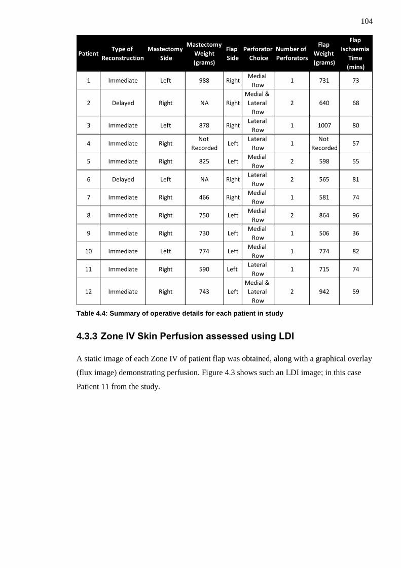
104
Table 4.4: Summary of operative details for each patient in study
4.3.3 Zone IV Skin Perfusion assessed using LDI
A static image of each Zone IV of patient flap was obtained, along with a graphical overlay
(flux image) demonstrating perfusion. Figure 4.3 shows such an LDI image; in this case
Patient 11 from the study.
PatientType of
Reconstruction
Mastectomy
Side
Mastectomy
Weight
(grams)
Flap
Side
Perforator
Choice
Number of
Perforators
Flap
Weight
(grams)
Flap
Ischaemia
Time
(mins)
1 Immediate Left 988 RightMedial
Row1 731 73
2 Delayed Right NA Right
Medial &
Lateral
Row
2 640 68
3 Immediate Left 878 RightLateral
Row1 1007 80
4 Immediate RightNot
RecordedLeft
Lateral
Row1
Not
Recorded57
5 Immediate Right 825 LeftMedial
Row2 598 55
6 Delayed Left NA RightLateral
Row2 565 81
7 Immediate Right 466 RightMedial
Row1 581 74
8 Immediate Right 750 LeftMedial
Row2 864 96
9 Immediate Right 730 LeftMedial
Row1 506 36
10 Immediate Left 774 LeftMedial
Row1 774 82
11 Immediate Right 590 Left Lateral
Row1 715 74
12 Immediate Right 743 Left
Medial &
Lateral
Row
2 942 59
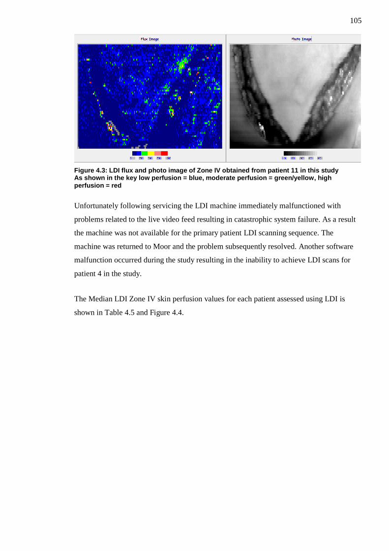
105
Figure 4.3: LDI flux and photo image of Zone IV obtained from patient 11 in this study As shown in the key low perfusion = blue, moderate perfusion = green/yellow, high perfusion = red
Unfortunately following servicing the LDI machine immediately malfunctioned with
problems related to the live video feed resulting in catastrophic system failure. As a result
the machine was not available for the primary patient LDI scanning sequence. The
machine was returned to Moor and the problem subsequently resolved. Another software
malfunction occurred during the study resulting in the inability to achieve LDI scans for
patient 4 in the study.
The Median LDI Zone IV skin perfusion values for each patient assessed using LDI is
shown in Table 4.5 and Figure 4.4.
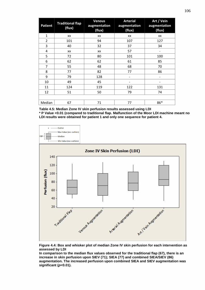
106
Patient Traditional flap
(flux)
Venous augmentation
(flux)
Arterial augmentation
(flux)
Art / Vein augmentation
(flux)
1 xx xx xx xx
2 101 94 107 127
3 40 32 37 34
4 xx xx 57 -
5 72 80 101 100
6 62 62 61 85
7 55 48 68 70
8 77 82 77 86
9 79 128 - -
10 49 45 - -
11 124 119 122 131
12 51 50 79 74
Median 67 71 77 86*
Table 4.5: Median Zone IV skin perfusion results assessed using LDI * P Value <0.01 (compared to traditional flap. Malfunction of the Moor LDI machine meant no LDI results were obtained for patient 1 and only one sequence for patient 4.
Figure 4.4: Box and whisker plot of median Zone IV skin perfusion for each intervention as assessed by LDI In comparison to the median flux values observed for the traditional flap (67), there is an increase in skin perfusion upon SIEV (71); SIEA (77) and combined SIEA/SIEV (86) augmentation. The increased perfusion upon combined SIEA and SIEV augmentation was significant (p<0.01).

107
Perfusion data was widely distributed but the box and whisker plot shows a trend to
increasing perfusion by unclamping the various components of the superficial vascular
system. The largest observed increase in Zone IV perfusion is observed when the flap is
augmented using both the SIEA and SIEV.
Data was found to be normally distributed and the results of a repeated measures ANOVA
showed there to be a statistically significant difference between the clamping interventions.
(p=0.008). (See Appendix A)
Assessment for differences between the traditional flap and the various vascular
augmentation interventions by the Bonferroni correction method are summarised in Table
4.6
Type of vascular
augmentation
Difference of mean perfusion traditional vs vascular augmentation
(flux)
Lower 95% Confidence
Interval
Upper 95% Confidence
Interval
Adjusted p-value
Venous augmentation
+3 -8.884 14.88 1.0000
Arterial augmentation
+11.19 -1.763 24.14 0.1073
Arterial and Venous
augmentation +18.06 5.112 31.01 0.0045*
Table 4.6: Bonferroni correction pairwise comparisons between traditional flap and vascular augmentation interventions
Zone IV skin perfusion was found to be significantly increased upon vascular
augmentation of flaps with both the SIEA and SIEV (p=0.0045)
4.3.4 Zone IV skin perfusion assessed using ICG Angiography
A greyscale image of the area being scanned along with a correlating visual graphical
display was also obtained. (See Figure 4.5)

108
Figure 4.5: SPY scan of Zone IV of patient 11 in this study low perfusion = blue, moderate perfusion = yellow/orange and high perfusion = red
The Zone IV skin perfusion values for each patient assessed using ICG angiography is
shown in Table 4.7 and Figure 4.6.

109
Patient Traditional flap
(units)
Venous augmentation
(units)
Arterial augmentation
(units)
Art / Vein augmentation
(units)
1 52 69 100 107
2 53 74 76 55
3 28 50 49 43
4 94 42 207 144
5 58 36 88 134
6 150 148 20 88
7 19 35 73 83
8 46 34 45 20
9 51 128 - -
10 23 16 - -
11 79 107 125 53
12 95 108 63 17
Median 53 60 75 83
Table 4.7: Mean Zone IV skin perfusion results assessed using ICG angiography
Figure 4.6: Box and whisker plot of median Zone IV skin perfusion for each intervention as assessed by ICG angiography In comparison to the Traditional Flap (53) there is increased skin perfusion upon SIEV (60), SIEA (75) and combined SIEV/SIEA (83) augmentation. Although these results did not reach significance (p>0.05).
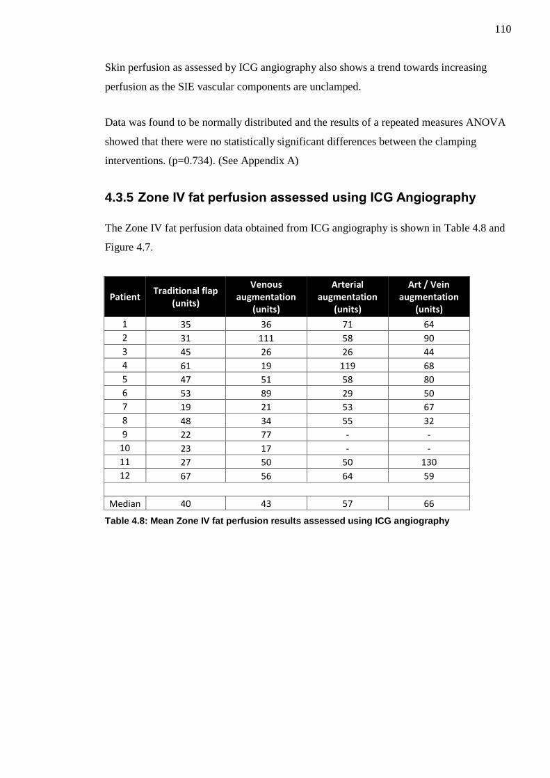
110
Skin perfusion as assessed by ICG angiography also shows a trend towards increasing
perfusion as the SIE vascular components are unclamped.
Data was found to be normally distributed and the results of a repeated measures ANOVA
showed that there were no statistically significant differences between the clamping
interventions. (p=0.734). (See Appendix A)
4.3.5 Zone IV fat perfusion assessed using ICG Angiography
The Zone IV fat perfusion data obtained from ICG angiography is shown in Table 4.8 and
Figure 4.7.
Patient Traditional flap
(units)
Venous augmentation
(units)
Arterial augmentation
(units)
Art / Vein augmentation
(units)
1 35 36 71 64
2 31 111 58 90
3 45 26 26 44
4 61 19 119 68
5 47 51 58 80
6 53 89 29 50
7 19 21 53 67
8 48 34 55 32
9 22 77 - -
10 23 17 - -
11 27 50 50 130
12 67 56 64 59
Median 40 43 57 66
Table 4.8: Mean Zone IV fat perfusion results assessed using ICG angiography

111
Figure 4.7: Box and whisker plot of median Zone IV fat perfusion for each intervention as assessed by ICG angiography In comparison to the Traditional Flap (40) there is increased fat perfusion upon SIEV (43), SIEA (57) and combined SIEV/SIEA (66) augmentation. Although these results did not reach significance (p>0.05).
The above box and whisker plot is similar to both the LDI and ICG skin perfusion scan
results and it appears that there is also a trend towards increasing Zone IV fat perfusion
upon vascular augmentation of the flap. The largest increase in fat perfusion is when both
the SIEA and SIEV are used in combination to augment the flap.
Data was found to be normally distributed and the results of a repeated measures ANOVA
showed there were no statistically significant differences between the clamping
interventions. (p=0.130). (See Appendix A)
4.3.6 Effect of Perforator Row
The effect of the perforator row, upon which the DIEP flap was raised (i.e. medial, lateral
or medial and lateral row), on Zone IV perfusion between the clamping interventions was
assessed using a repeated measures ANOVA.

112
The perforator row did not have any statistically significant effect on Zone IV skin
perfusion between clamping interventions as assessed by LDI (p=0.652). This was also
true of Zone IV skin (p=0.753) and fat (p=0.081) perfusion as assessed by ICG
angiography.
4.3.7 Effect of Perforator Number
The effect of number of perforators upon which the DIEP flap was raised on Zone IV
perfusion between the clamping interventions was assessed using a repeated measures
ANOVA.
The number of perforators did not have any statistically significant effect on Zone IV skin
perfusion between clamping interventions as assessed by LDI (p=0.678). This was also
true of Zone IV skin (p=0.695) and fat (p=0.079) perfusion as assessed by ICG
angiography.
4.3.8 Sub-analysis excluding Patient 6
Total flap loss occurred in Patient 6 of our cohort. A separate sub-analysis was undertaken
using a repeated measures ANOVA after exclusion of this patient.
There was still a statistically significant difference observed in LDI assessed skin perfusion
(p=0.021) between the clamping interventions. Bonferroni correction pairwise comparison
tests between the traditional flap and the clamping interventions showed that the only
significant difference was observed when both the SIEA and SIEV were unclamped
(p=0.0156).
There was still no statistically significant differences in ICG assessed Zone IV skin
(p=0.161) or fat (p=0.055) perfusion between clamping interventions.
4.3.9 Sub-analysis excluding Patients 9 and 10
Patient 9 and 10 within this study did not have an SIEA. A separate sub-analysis was
undertaken using a repeated measures ANOVA after exclusion of these patients.
There was still a statistically significant difference observed in LDI assessed skin perfusion
(p=0.001) between the clamping interventions. Bonferroni correction pairwise comparison

113
tests between the traditional flap and the clamping interventions showed that the only
significant difference was observed when both the SIEA and SIEV were
unclamped(p=0.0018).
There was still no statistically significant differences in ICG assessed Zone IV skin
(p=0.791) or fat (p=0.159) perfusion between clamping interventions.
4.4 Discussion
Our results show that there is a trend towards increasing Zone IV skin and fat perfusion in
DIEP flaps when the flap is augmented using the contralateral superficial vascular system.
The largest observed increase to Zone IV perfusion is when both the SIEA and SIEV are
used in combination to augment the flap. However, this was only statistically significant in
Zone IV skin perfusion as assessed by LDI (p=0.0045).
4.4.1 Augmentation with the SIEA, SIEA or Both
There are very few human in-vivo studies assessing the effects of contralateral arterial or
venous augmentation of abdominal flaps however there are a multitude of experimental
studies looking at the importance of venous drainage or arterial inflow in rat abdominal
flaps.
Miles et al in 1997 published their findings comparing the effects of different venous
interventions carried out upon 40 rat pedicled abdominal flaps. In this study their
intervention groups consisted of a simple pedicled flap; a pedicled flap with additional
contralateral venous augmentation, a venous only pedicled flap and an arterialised venous
flap. They found that in the 25 flaps suitable for analysis at the end of their study that the
only significant increase in flap survivability was found in flaps with additional
contralateral venous augmentation164
. Hallock and Rice in 2005 compared a traditional rat
DIEP flap model versus DIEP flap models augmented with the contralateral vein and
found that there was a statistically significant increased flap viability in the venous
augmented group163
.
Chang et al in 2004 analysed the effects of various arterial augmentation procedures on 40
rats. They found that the augmentation of rat abdominal flaps with the contralateral arterial
system led to a statistically significant improvement in flap survival162
.

114
Several experimental studies have looked at whether arterial or venous augmentation is
most important in terms of flap survival. In an early study in 1982 by Nakayama et al
investigating the effects of arterial input or venous drainage upon distal necrosis in
abdominal skin flaps raised on 45 rats. They individually compared the effects of arterial
or venous augmentation to the survivability of the distal portion of these skin flaps. They
found that arterial augmentation seemed to be the most crucial in determining flap
survivability. Despite not looking at arterial and venous augmentation in combination they
still recommended that where possible both additional venous drainage and arterial input
be used where possible165
.
In a study very similar to our own from 1994 Ueda et al divided 32 rat TRAM type
abdominal flaps into four cohorts166
. Cohort one had a flap augmented with the
contralateral SIEA and SIEV; cohort two had augmentation with the SIEA only; cohort
three SIEV augmentation only and cohort 4 a standard ipsilateral based flap. They found
that cohort one and two had complete flap survivability in comparison to the others. In
cohort two there was significant flap oedema post-operatively but this settled by day 4.
They suggested that both an artery and vein should be utilised to augment flaps where
possible but believed the arterial input to be most important. Similarly in 2009 Yamamoto
et al assessed the importance of the contralateral SIEA/SIEV in a rat DIEP flap model167
.
They separated 30 rats into three cohorts; SIEA/SIEV both divided; SIEA intact/SIEV
divided and SIEA divided/SIEV intact. They assessed overall flap survival area and also
pressure within the venous system. Despite large variation amongst the individual rat flaps
they found a statistically significant increase in flap area survival occurred in the rats with
the SIEA intact.
Our in-vivo perfusion results complement the experimental results found by Ueda’s and
Yamamoto’s research groups166,167
although our only significant finding in terms of
increased perfusion was when both the contralateral SIEA and SIEV were present.
Despite the fact only the LDI results reached statistical significance when the flaps were
augmented using the contralateral SIEA and SIEV there were large differences in median
perfusion observed between the traditional flap and flaps augmented with the SIEA alone
and the SIEA+SIEV in both the LDI and ICG angiography groups; this could indicate that
these increases in perfusion could be clinically relevant and the reason they failed to reach
statistical significance was due to the power of our pilot study. The SIEV augmentation
intervention alone seemed to have little effect on skin and fat perfusion.
115
4.4.1.1 Variability of the SIEA
During our study we found the SIEA to be completely absent in two (16.7%) of our
patients (patients 9 and 10). This absence rate is similar to the 13% found by Stern and
Nahai in 1995 in their series of 31 patients but lower than the 35% quoted by Taylor and
Daniel in 1975 in their original anatomical dissections of 100 cadavers66
or the 51% as
quoted in-vivo by Chevray in 2004 on their experience of 47 consecutive abdominal flap
breast reconstructions65
. Given that absence of the SIEA may represent altered flap
vascular anatomy a separate sub-analysis of our results was undertaken excluding patient 9
and 10. However, this still showed that there was only statistically significant effect on
Zone IV Skin perfusion assessed by LDI when both the SIEA and SIEV were used to
augment the flap.
Patient 4 in our study cohort had large outlying perfusion values as assessed by ICG
angiography when the flap was arterially augmented using the contralateral SIEA. This is
particularly interesting secondary to the odd vascular anatomy encountered in dissecting
this patients contralateral SIE vascular system. Both the SIEA and SIEV in this patient
were found to be sub-Scarpa in nature. We could find no other descriptions in the literature
of these vessels noted to be in the sub-Scarpa plane and the influence of such vessels in
perfusion of DIEP flaps is unknown. The large increase in perfusion as shown in the ICG
angiography scans could indeed be due to increased arterial inflow to Zone IV or could be
due to venous pooling secondary to poor vascular draining of the area by a SIEV in the
sub-Scarpa plane. Unfortunately the LDI malfunctioned during this patients scanning
sequence and we did not have these scans to correlate our ICG angiography findings with.
4.4.1.2 Other factors affecting patient outcome
One flap loss occurred in Patient 6 of our study cohort. This flap showed some intra-
operative evidence of venous congestion upon initial raising and even prior to detachment
from the abdomen. Upon detachment and transfer of this flap; despite multiple additional
venous augmentation procedures (contralateral SIEV to distal IMV augmentation and then
interposition vein graft from ipsilateral SIEV to secondary DIEV venae comitantes) the
flap failed secondary to worsening venous congestion and the flap required debridement 5
days post operatively. Given the intra-operative findings of venous congestion and
subsequent flap loss it may represent different intra-flap vascular anatomy and as such a
separate sub-analysis of our results was undertaken excluding patient 6. This still showed
116
that there was only statistically significant effect on Zone IV Skin perfusion assessed by
LDI when both the SIEA and SIEV were used to augment the flap.
4.4.2 Model validation and potential confounders
4.4.2.1 Zone IV selection
Whilst controversy remains over which area of the DIEP flap should be designated Zone II
or Zone III there is global consensus on which area is Zone IV. Zone IV is the area of the
flap which is subject to the worst perfusion and resultant complications of venous
congestion; fat necrosis and partial flap loss. As a result of the doubtful viability and also
the fact that Zone IV can be difficult to incorporate geometrically into a reconstruction
whilst trying to recreate a suitable breast shape, many surgeons would routinely discard
this section of the flap and we accept that this is the least useful portion of the flap
clinically. However, in terms of translational research, Zone IV is most likely to resemble a
failing flap model and thus the results of vascular augmentation may be of particular
interest to the microsurgical community as a whole as this may give evidence for the use of
vascular augmentation procedures to salvage failing flaps. We believed that the effect of
any vascular augmentation procedure is likely to be most obvious in Zone IV. Additionally
Zone IV is also routinely discarded by the senior operating surgeon involved in this study
and in terms of ethical accountability any potential consequences to the survivability of
Zone IV secondary to our interventions (i.e. clamping of SIE vascular system) or any
unexpected intra-operative findings to this area of the flap during our study would have no
influence to our patients’ normal standard of care. We accept that it would have been
favourable to have analysed all Zones of the flap during this research study; however it
would have significantly added to each patients length of anaesthesia and operation and we
could not ethically justify the additional time required. Longer operating times have been
associated with increased risks of post-operative complications218
. The research performed
in this study was performed during a routine twenty minute interval, undertaken after the
flap was initially raised, to allow time for any areas of potential vascular concern within
the flap to identify themselves and allow a natural comfort break as per the operating
surgeons’ standard practice. Thus our study did not lengthen the patients’ anaesthesia or
operation time.

117
4.4.2.2 Clamping Intervention
In this procedure five minutes was allowed to elapse after any clamping or unclamping
intervention prior to taking any scanning measurements to allow reactive hyperaemia to
settle. This was decided upon following review of the evidence from a previous study by
Tollan et al which has shown that a period of five minutes is an adequate amount of time to
allow reactive hyperaemia to settle following clamping and unclamping of vasculature in
DIEP flaps211
.
4.4.2.3 Data Sampling and Analysis
During sampling and analysis of the LDI and ICG angiography scan images for each
patient; defined regions of interest were selected within each flap (Zone IV) in order to
obtain the perfusion values within this area. For each separate patient scan (assessing
interventions) this region of interest had to be individually selected. Whilst care was taken
to select the same region of interest for each patient scan; this user-defined area can be
considered arbitrary in nature. In an effort to reduce bias several precautions were taken.
Flaps were divided and marked on the operating table into the classical Hartrampf Zones of
Perfusion prior to the commencement of the operation and these markings can be
visualised on both the LDI and ICG angiography scan images whilst undergoing analysis
essentially acting as a reference point upon which to select the region of interest. Only
Zone IV of the flap was scanned during each intervention process and thus the area to
select as the region of interest was minimised. All patient scans were undertaken and
analysed using the same method by the same observer, with training and previous
experience in both the scan capture and analysis. The median (LDI) and mean (ICG) scan
results for each area of interest were utilised rather than individual points of reference and
thus any minor inaccuracies in terms of area selected are unlikely to influence the overall
results obtained significantly. Despite these precautions the specified location and area
encompassed by the “region of interest” are therefore accepted as a potential confounder.
4.4.2.4 Choice of medial or lateral row perforator
Six patients in our study had DIEP flaps based upon medial row perforators; four upon
lateral row perforators and two had flaps based upon both medial and lateral row
perforators. Perforator selection in this study was based clinically upon what appeared to
be the largest dominant perforating vessel offering easiest dissection with minimal
collateral damage. Studies have suggested that medial row perforators cross the midline
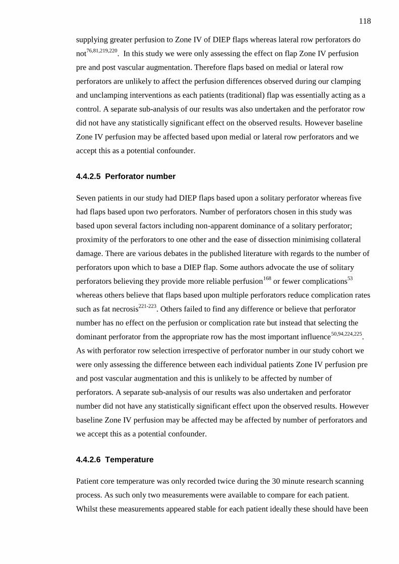
118
supplying greater perfusion to Zone IV of DIEP flaps whereas lateral row perforators do
not76,81,219,220
. In this study we were only assessing the effect on flap Zone IV perfusion
pre and post vascular augmentation. Therefore flaps based on medial or lateral row
perforators are unlikely to affect the perfusion differences observed during our clamping
and unclamping interventions as each patients (traditional) flap was essentially acting as a
control. A separate sub-analysis of our results was also undertaken and the perforator row
did not have any statistically significant effect on the observed results. However baseline
Zone IV perfusion may be affected based upon medial or lateral row perforators and we
accept this as a potential confounder.
4.4.2.5 Perforator number
Seven patients in our study had DIEP flaps based upon a solitary perforator whereas five
had flaps based upon two perforators. Number of perforators chosen in this study was
based upon several factors including non-apparent dominance of a solitary perforator;
proximity of the perforators to one other and the ease of dissection minimising collateral
damage. There are various debates in the published literature with regards to the number of
perforators upon which to base a DIEP flap. Some authors advocate the use of solitary
perforators believing they provide more reliable perfusion168
or fewer complications53
whereas others believe that flaps based upon multiple perforators reduce complication rates
such as fat necrosis221-223
. Others failed to find any difference or believe that perforator
number has no effect on the perfusion or complication rate but instead that selecting the
dominant perforator from the appropriate row has the most important influence50,94,224,225
.
As with perforator row selection irrespective of perforator number in our study cohort we
were only assessing the difference between each individual patients Zone IV perfusion pre
and post vascular augmentation and this is unlikely to be affected by number of
perforators. A separate sub-analysis of our results was also undertaken and perforator
number did not have any statistically significant effect upon the observed results. However
baseline Zone IV perfusion may be affected may be affected by number of perforators and
we accept this as a potential confounder.
4.4.2.6 Temperature
Patient core temperature was only recorded twice during the 30 minute research scanning
process. As such only two measurements were available to compare for each patient.
Whilst these measurements appeared stable for each patient ideally these should have been

119
recorded prior to each individual scan. Thus inadequate patient temperature recording is
accepted as a design limitation and potential confounder.
4.4.2.7 Control Patient
No control patient, not undergoing any clamping intervention but undergoing the same
number of scans to that of the research patient cohort, was included in this study. Since
patients’ own flaps were being used as a control (i.e. traditional flap versus vascular
augmetation intervention) we did not believe an additional control patient would add much
in terms of validity to the experiment as both the clamping interventions and scanning
processes have been validated in previous studies212,226
. In a similar fashion we did not feel
it beneficial to scan individual patients abdomens prior to raising the flap as a control for
“normal values” as it has been shown in the literature that upon raising a flap the blood
supply grossly changes in comparison to pre-operative values227
.
4.4.2.8 Performance Bias
All flap dissection and raising in this study was by a single senior Consultant Plastic
Surgeon with significant experience in the technique. Mr Mackay’s failure rate for free
DIEP flap breast reconstruction is less than 2% over the past five year period; well below
the quoted acceptable range of less than 5%90
for free tissue transfer and in keeping with
the 1.95% quoted in the National Mastectomy and Breast Reconstruction Audit228
. All
flaps were raised as per his standard protocol and given his career experience in the
technique performance bias is likely to be minimal but we accept it as a potential
confounder.
4.4.3 Conclusion
In conclusion from the findings of our initial pilot study we believe that vascular
augmentation of DIEP flaps using the contralateral SIE vascular system leads to an
increase in Zone IV perfusion. Our results show that the biggest increase in Zone IV
perfusion occurs when flaps are augmented using both the SIEA and SIEV in combination.
Therefore from our preliminary work we would suggest that when Zone IV of a DIEP flap
is to be incorporated into the reconstruction rather than being discarded that both
components of the SIE vascular system (SIEA and SIEV) are used to augment the flap.

120
Chapter 5: The effects of vascular augmentation on abdominal flap Zone I / IV perfusion and main pedicle arterial blood flow in an experimental animal model
5.1 Introduction
In 2001 Oskar et al were the first to describe an experimental animal model upon which to
raise perforator flaps214
. In their study they successfully raised abdominal flaps in Sprague
Dawley rats based upon solitary musculocutaneous perforators and found that these flaps
had similar areas of survival to traditionally used random pattern pedicled flaps raised in
rats. They proposed that the rat was a reliable experimental model for further research into
perforator flaps. This model was further validated subsequently by Ozkan et al in 2006229
.
Whilst the vascular supply to the lower abdominal tissue is similar in rats and humans
there are several differences which must be taken into account when using the rat
abdominal perforator flap model. In humans the dominant blood supply to the lower
abdominal tissue comes from the caudal DIE vessels (cf. 1.5) whereas in rats the dominant
supply comes from the cranial Deep Superior Epigastric (DSE) vessels230,231
. (See Figure
5.1)
Figure 5.1: Contrast injection study in Sprague Dawley rat showing dominance of cranial (DSE) vessels Image reproduced with permission from Wolters Kluwer Health, Inc. (Hallock & Rice 1995)
230
Thus any perforator flaps based upon the lower abdominal tissue in rats must take account
of this cranial dominance and factor it in to any research studies using the model opting

121
instead to base the perforator flaps on the DSE vessels. Another major anatomical
difference is that unlike the defined medial and lateral rows branching from the deep
source vessels in humans, there is no such defined branching pattern in the deep vessels of
rats230
. As such it is not possible to perform research based upon medial or lateral rows in
the rat abdominal model.
Despite these anatomical vascular differences since the description by Oskar et al214
the rat
abdominal perforator flap model as an analogue to human abdominal perforator flaps has
become widely accepted and established in plastic surgery research94,163,167,168
.
Whilst our own study (cf. Chapter 4) suggests that vascular augmentation of the DIEP flap
will lead to a greater perfusion of Zone IV, the concern would be that the addition of
another supplementary pedicle could potentially lead to a decreased main pedicle blood
flow and overall flap perfusion in a similar way to that occurring when more than one
perforator is utilised as found by Douglas et al168
. There were no studies addressing this
concern in the literature.
The aim of this experimental study was to assess in-vivo, using a rat abdominal flap model
as an analogue to a DIEP flap, the effects on Zone I / IV perfusion and on main pedicle
arterial blood flow by vascular augmentation using the contralateral vascular system.
5.2 Methods
In a randomised fashion (cf. 3.2.5) left or right islanded abdominal flaps were raised in 12
Sprague Dawley rats so that the flap was obtaining its vascular supply from a pedicle
containing the cranial most perforating artery and vein from the DSEA and DSEV (main
pedicle) on one side of the flap and the contralateral DSEA and DSEV pedicle (vascular
augment pedicle) containing only the caudal most perforating artery and vein (cf. 3.2.9).
Flaps were divided into Hartrampf’s four Zones of perfusion (cf. 1.6.4). The vascular
augment pedicle was clamped and unclamped and the resultant effects on Zone I and Zone
IV perfusion assessed using LDF flowmetry (cf. 3.2.7.2). The effect of the vascular
augment intervention on blood flow through the main pedicle was also assessed using
transit-time ultrasound flowmetry (cf. 3.2.8.3).

122
5.3 Results
5.3.1 Animals
Twelve consecutive male outbred Sprague Dawley rats; obtained from Harlan UK Ltd.,
Bicester, Oxfordshire, UK; were used in this research carried out between 31/01/2013 to
04/03/2013. Seven animals (58%) were randomised to have a flap based upon the right
side and the five upon the left (42%). The average weight of the animals used in this study
was 344grams.
A summary of animal demographics and mean intra-operative measurements are shown in
Table 5.1.
Animal Weight (grams)
Flap side
Oxygen saturation
(%)
Heart rate
(bpm)
Core temperature
(°C)
1 343 Right 98.5 382 37.2
2 351 Left 98 390 37.7
3 335 Right 99 386 37.7
4 343 Left 98 333 37.9
5 353 Right 97 380 37.6
6 377 Left 98 428 38.0
7 366 Left 97.5 376 37.5
8 386 Left 98 367 37.8
9 300 Right 99.5 381 37.3
10 314 Right 99 349 37.3
11 323 Right 99 344 37.0
12 333 Right 96 368 37.2
Table 5.1: Summary of pre and peri-operative characteristics
5.3.2 Perfusion
5.3.2.1 Zone I vs Zone IV perfusion
Perfusion values obtained for Zone I and Zone IV in the traditional flap model and in the
vascular augmented flap model are shown in Table 5.2 and Figure 5.2.

123
Animal
Perfusion (flux)
Zone I Zone IV
1 27.5 18.1
2 36.1 12.9
3 51.7 13.9
4 31.7 20.1
5 23.3 16.9
6 89 37.5
7 22.9 7.7
8 91.7 5.0
9 97.7 23.4
10 37.9 16.2
11 24.9 17.5
12 58.9 21.9
Median 37 17.2
Table 5.2: Mean Zone I/IV perfusion of the traditional flaps
Figure 5.2: Box and whisker plot of median Zone I versus Zone IV perfusion in a traditional flap In a traditional flap Zone I (37.0) perfusion is significantly higher than Zone IV (17.2) perfusion (p<0.01).

124
It is obvious from the figure above that there is a greater degree of perfusion in Zone I in
comparison to Zone IV.
The effects of vascular augmentation on abdominal flap Zone I vs Zone IV perfusion are
shown in Table 5.3 and Figure 5.3.
Animal
Perfusion (flux)
Zone I Zone IV
1 16.5 19.5
2 34.9 13.4
3 45.0 23.8
4 26.8 21.0
5 19.5 28.8
6 74.1 35.0
7 14.9 14.9
8 64.7 12.8
9 43.2 49.5
10 58.8 62.4
11 20.5 24.8
12 44.7 32.1
Median 39.1 24.3
Table 5.3: Mean Zone I/IV perfusion of vascular augmented flaps
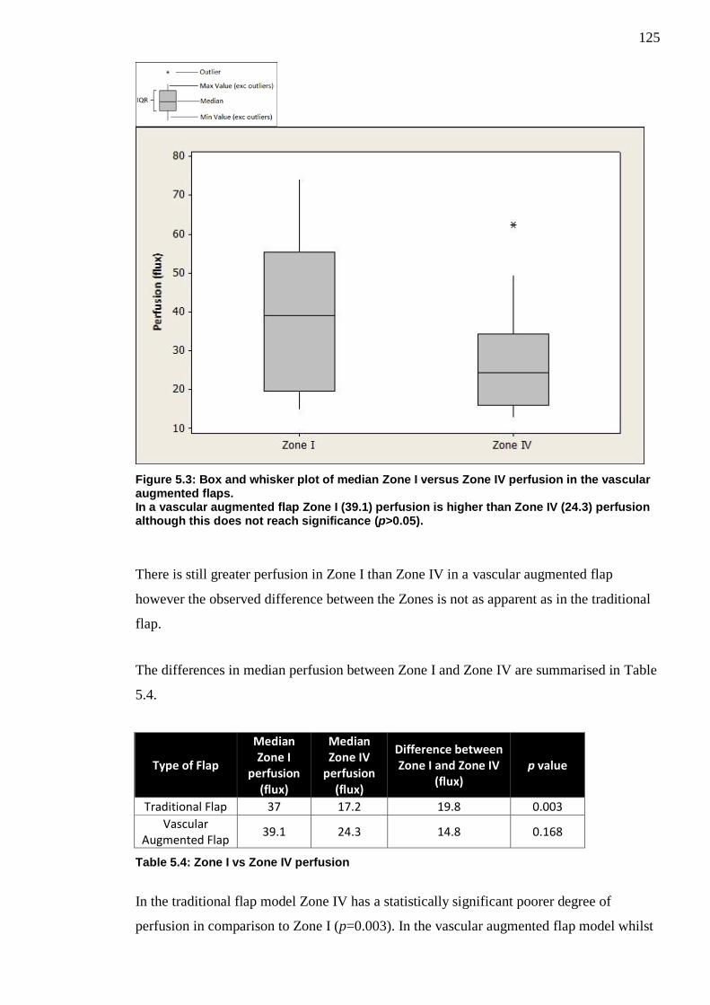
125
Figure 5.3: Box and whisker plot of median Zone I versus Zone IV perfusion in the vascular augmented flaps. In a vascular augmented flap Zone I (39.1) perfusion is higher than Zone IV (24.3) perfusion although this does not reach significance (p>0.05).
There is still greater perfusion in Zone I than Zone IV in a vascular augmented flap
however the observed difference between the Zones is not as apparent as in the traditional
flap.
The differences in median perfusion between Zone I and Zone IV are summarised in Table
5.4.
Type of Flap
Median Zone I
perfusion (flux)
Median Zone IV
perfusion (flux)
Difference between Zone I and Zone IV
(flux) p value
Traditional Flap 37 17.2 19.8 0.003
Vascular Augmented Flap
39.1 24.3 14.8 0.168
Table 5.4: Zone I vs Zone IV perfusion
In the traditional flap model Zone IV has a statistically significant poorer degree of
perfusion in comparison to Zone I (p=0.003). In the vascular augmented flap model whilst
126
there still appears to be a greater degree of perfusion in Zone I when compared to Zone IV
however this difference is no longer statistically significant (p=0.168).
5.3.2.2 Traditional Flap vs Vascular Augmented Flap
Perfusion values in Zone I and Zone IV in the traditional flap model and the vascular
augmented flap model area summarised in Table 5.5 and Figure 5.4.
Zone I Perfusion (flux) Zone IV Perfusion (flux)
Animal Traditional
Flap Vascular
Augmented Flap Traditional
Flap Vascular
Augmented Flap
1 27.5 16.5 18.1 19.5
2 36.1 34.9 12.9 13.4
3 51.7 45 13.9 23.8
4 31.7 26.8 20.1 21
5 23.3 19.5 16.9 28.8
6 89 74.1 37.5 35
7 22.9 14.9 7.7 14.9
8 91.7 64.7 5 12.8
9 97.7 43.2 23.4 49.5
10 37.9 58.8 16.2 62.4
11 24.9 20.5 17.5 24.8
12 58.9 44.7 21.9 32.1
Median 37 39.1 17.2 24.3
Table 5.5: Mean Zone I and Zone IV perfusion for traditional flaps versus vascular augmented flaps

127
Figure 5.4: Box and whisker plot of median LDF perfusion in Zone I and Zone IV for traditional and vascular augmented flaps Vascular Augmentation of the traditional flap significantly improves Zone I (p<0.05) and to a greater degree Zone IV (p<0.01) perfusion.
It can be observed from the box and whisker plot that there is an increase in Zone IV
perfusion upon vascular augmentation of the flap.
Traditional versus vascular augmented flap differences in both Zones are summarised in
Table 5.6.
Flap Zone
Traditional flap perfusion (flux)
Vascular Augmented flap perfusion (flux)
Difference in perfusion traditional vs vascular augmentation (flux)
p value
I 37 39.1 +2.1 0.025
IV 17.2 24.3 +7.1 0.007
Table 5.6: Traditional versus vascular augmented flap
From our results it is evident that vascular augmentation of the abdominal flap leads to a
statistically significant increase in in Zone IV perfusion (p=0.007). The spread of data was
wide but there also appears to be an increase in Zone I perfusion, although to a much
smaller degree. (p=0.025).

128
5.3.3 Flow
Flow values observed through the main pedicle DSEA in the traditional flap and the
vascular augmented flap for each animal are shown in Table 5.7 and Figure 5.5.
Animal
Flow ml/min
Traditional Flap Vascular Augmented Flap
1 0.25 0.23
2 0.33 0.3
3 0.48 0.43
4 0.29 0.2
5 0.3 0.15
6 0.34 0.29
7 0.42 0.37
8 0.37 0.36
9 0.45 0.31
10 0.48 0.45
11 0.29 0.25
12 0.79 0.65
Median 0.37 0.31
Table 5.7: Main DSEA flow in the traditional flap model compared to the vascular augmented flap model

129
Figure 5.5: Box and whisker plot of median main pedicle blood flow rate in traditional versus vascular augmented flaps In comparison to the flow observed in a Traditional flap (0.37ml/min) the flow in a vascular augmented flap (0.31ml/mins) is significantly lower (p<0.01).
It is shown that there is great inter-animal variability for the rats used in this study with
regards to flow but there appears to be a decrease in flow through the main pedicle when
vascular augmentation of the abdominal flap is performed.
The effects of vascular augmentation on arterial blood flow through the main pedicle of the
abdominal flap are summarised in Table 5.8.
Type of Flap Flow (ml/min)
Traditional Flap 0.37
Vascular Augmented Flap 0.31
Difference in flow -0.06
p value 0.003
Table 5.8: Effect of abdominal flap vascular augmentation on main pedicle flow
From our results it has been shown that there is a statistically significant reduction in flow
through the main DSEA when vascular augmentation of the abdominal flap is performed.
(p=0.003)

130
5.3.3.1 Pulsatility Index
The pulsatility index was also calculated for each of the animals in this study and is shown
in Table 5.9 and Figure 5.6.
Animal
Pulsatility Index
Traditional Flap Vascular Augmented Flap
1 4.58 4.27
2 3.65 3.40
3 6.11 2.86
4 3.89 7.31
5 0.81 10.48
6 4.73 9.81
7 2.84 2.35
8 3.74 2.71
9 0.30 0.46
10 1.16 1.13
11 3.49 3.65
12 1.87 1.55
Median 3.49 2.86
Table 5.9: Pulsatility Index for traditional and vascular augmented flaps
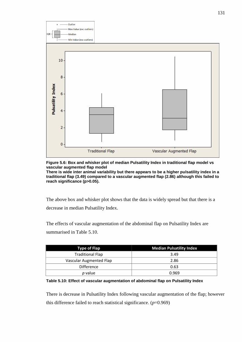
131
Figure 5.6: Box and whisker plot of median Pulsatility Index in traditional flap model vs vascular augmented flap model There is wide inter animal variability but there appears to be a higher pulsatility index in a traditional flap (3.49) compared to a vascular augmented flap (2.86) although this failed to reach significance (p>0.05).
The above box and whisker plot shows that the data is widely spread but that there is a
decrease in median Pulsatility Index.
The effects of vascular augmentation of the abdominal flap on Pulsatility Index are
summarised in Table 5.10.
Type of Flap Median Pulsatility Index
Traditional Flap 3.49
Vascular Augmented Flap 2.86
Difference 0.63
p value 0.969
Table 5.10: Effect of vascular augmentation of abdominal flap on Pulsatility Index
There is decrease in Pulsatility Index following vascular augmentation of the flap; however
this difference failed to reach statistical significance. (p=0.969)

132
5.4 Discussion
The results from our study show that in a traditional perforator abdominal flap and a
vascular augmented flap, perfusion was higher in Zone I when compared to Zone IV,
however this difference was only found to be statistically significant in the traditional flap
model. (p=0.003 vs p=0.168). Perfusion in Zone IV was increased significantly upon
vascular augmentation of the flaps (p=0.007) and the same was also found in Zone I
(p=0.025). There was also a significant reduction in main pedicle arterial flow when
vascular augmentation of the flap was performed (p=0.003) whilst the pulsatility index
decreased.
Our significant findings of increased perfusion as assessed by LDF in Zone I in
comparison to Zone IV helps to validate the rat perforator abdominal flap model used in
this study. Our animal study correlates with our human study in that vascular augmentation
of flaps leads to an overall increase in Zone IV perfusion. Zone I perfusion was also found
to have increased however there was found to be a reduction in main pedicle arterial flow
and pulsatility index.
5.4.1 Model Validation and Potential Confounders
5.4.1.1 Selection of Zone I and Zone IV
Zone I represents the area of best perfusion within a flap and Zone IV the area of worst
perfusion. This has been well shown in both human studies73-75,212
and in rat models94,226
. It
was for this reason that these zones were selected to compare in this study. Whilst it would
have been ideal to have measured the perfusion in all Zones of the rat perforator abdominal
flap model simultaneously this would not have been possible secondary to the small size of
the flaps. Despite using the smallest LDF probe it was incredibly difficult during this study
to site even two probes on the flaps concurrently. In order to measure all Zones it would
have required that 2-3 separate measurement periods be undertaken and this would have
led to less robust results as recording of the perfusion between Zones during exactly the
same interval, such as that measured in this study, could not have been undertaken.
5.4.1.2 Perfusion
Of the few studies using LDF to assess rat abdominal skin flap perfusion94,230,232,233
only a
recent animal model experiment by Douglas utilised the same LDF system and software as
133
that used in our study to allow comparison226
. In this study perforator abdominal flaps were
raised in 20 Wistar rats and the effects of perforator number and location on perfusion in
Zones I-IV were being assessed. Douglas found that mean Zone I perfusion (34.55units)
was higher than Zone IV perfusion (17.85) for flaps based on a cranial perforator. These
results correlate well with our findings that mean Zone I perfusion (49.44) is greater than
mean Zone IV perfusion (17.85) for similarly raised flaps. The slightly higher perfusion
values found in our study may be secondary to the difference in strain of rat used (Sprague
Dawley versus Wistar) and that our rats had a higher average weight (344grams versus
322grams). Despite the use of different LDF systems Hallock and Rice in an experimental
rat study using Sprague Dawley rats in 2004 also found Zone IV perfusion to be
significantly lower than that of Zone I further corroborating our findings94
.
5.4.1.3 Flow and Pulsatility Index
In a study by Rickard et al in 2009 investigating the development of a model to assess
microvascular anastomotic techniques in vessels with size mismatch, flow rates through
the femoral arteries of Wistar rats were assessed in the same fashion to that used in this
study234
. Flow rates of 2.39m1/min and 2.882ml/min are quoted which are significantly
greater than those found in our study. However, given that the femoral vessel was being
assessed in this study it is not surprising that the flow rates are much greater as the
diameter of the femoral artery is much larger than that of the superior epigastric.
In another study by Douglas assessing the effect of varying the number and location of
perforators on main pedicle arterial flow in Wistar rats, mean flow values of 0.21(range
0.09-0.4)ml/min are quoted for flaps raised on a cranial perforator168,226
. This is much
lower than the mean 0.40 (range 0.15-0.65)ml/min found in our cohort. However, there
was a great degree of variability between animals in both studies and again the difference
between strains in the rats used in each study and the larger weight of our rats could
account for the differences observed.
Only flow through the main pedicle DSEA was assessed during this study. In the animals
used in this study we found these vessels to be approximately 0.25-0.35mm in diameter. A
previous study assessing the microvascular transfer of free rectus abdominus
myocutaneous flaps in Sprague Dawley rats by Zhang et al has previously quoted that the
mean vessel diameter of the DSEA was 0.4-0.5mm235
. However the rats used in this study
were much larger than our own weighting between 400-500grams and this could account

134
for the observed difference. Whilst the microcirculation transit-time flow probes used in
this study can detect flow rates in vessels of 0.25-0.5mm we could not position 2
concurrently on both the artery and the vein due to the size of the probes without placing
undue tension on the vessels. We also found detection of flow within the vein to be
extremely difficult and as such only arterial flow rate was measured and we accept this as a
potential confounder.
We found that vascular augmentation of the rat abdominal flaps led to a significant
decrease in main arterial pedicle blood flow. A similar finding was found by Douglas, in
the aforementioned study, when assessing the total number of perforators upon which to
base a flap168
. She found that by increasing the number of perforators used to supply a flap
there was a decrease in main pedicle flow.
5.4.1.4 Perforator Selection
In all flaps raised in our animal cohort the ipsilateral most cranial perforator and the
contralateral most caudal perforator were selected upon which to base the flaps and
perform the study. The reasoning behind this choice of perforator configuration was in
terms of translational research as it is likely to be the most useful in terms of potential
vascular augmentation of flaps. By having such a perforator configuration it allows the
maximal pedicle length available (without the use of interposition grafts) to subsequently
augment a flap. For example if this configuration was chosen in a human subject the entire
length of the ipsilateral DIEA and DIEV distal to the first perforator (caudal in humans)
would be available to potentially use as afferent vessels to augment the flap. Conversely
the entire length of the contralateral DIEA and DIEV from proximal to the last perforator
(cranial in humans) to their origin would be available as recipient/efferent vessels upon
which to perform vascular augmentation of the flap.
5.4.1.5 Genetic Variability of Animal
All rats used in this study were male out-bred Sprague Dawley rats. Sprague Dawley rats
are the most commonly used out-bred strain of rat in experimental research236
and have
been used extensively in abdominal flap models94,162,163,214,229,230
. We accept the genetic
variability of the out-bred strain as a potential confounder however our justification for
utilising this strain was that they tend to be of a larger size and thus any experiments
requiring meticulous dissection of the small perforating blood vessels more feasible and
less prone to complications.
135
5.4.1.6 Performance bias
A single surgeon with some previous microsurgical experience was responsible for
performing all procedures and measuring the results. However as exposure/experience was
gained in rat abdominal perforator flap dissection and raising it is feasible that flaps were
raised quicker and more efficiently in the latter animals in the cohort and we accept this as
a potential confounder. Potential consequences of efficient flap raising could be that those
animals in the latter part of our study would have higher rates of flow and perfusion
secondary to shorter anaesthetic time to reach that point. However given that we were
comparing the difference in perfusion and flow between the traditional flap (essentially
control) against the vascular augmented flap on each individual rat it is unlikely that this
will have affected our results.
5.4.1.7 Temperature
Temperature is known to influence cutaneous blood flow as shown by Bircher et al208
and
also the transit-time ultrasonic probes used to measure flow are calibrated to operate at
approximately 37°C. As such room temperature in this experiment was kept constant
between 21-24.5°C and the animal temperature continuously monitored by specialist
animal technicians and attempts to maintain core temperature made at 37-38°C using an
ambient heat source. Mean temperature for all animals was stable and kept within this
range. However we accept that temperature can be a confounding factor.
5.4.1.8 Intra-observer error
All results were analysed by the same individual, to reduce inter-observer error; however
the possibility of intra-observer error remains and we accept this as a potential confounder.
5.4.2 Conclusion
In conclusion from the findings of our study it has been shown that vascular augmentation
of the rat abdominal perforator flap using the contralateral pedicle leads to an increase in
Zone IV perfusion however this also coincides with a decrease in main pedicle arterial
flow. Further studies in this area are required to assess if these findings correlate in human
subjects.

136
Chapter 6: The use of real-time digital video in the assessment of post-operative outcomes of breast reconstruction.
6.1 Introduction
Standardised pre and post-operative photographs are still the most commonly used method
of recording breast reconstruction outcomes. Whilst this method is readily available and
reproducible it is inherently flawed by the fact that the images obtained are static and two
dimensional. These images only provide limited information to the assessor and it is
difficult to ascertain the degree of volume associated with the reconstruction.
Recently more complex methods of assessment utilising three-dimensional capture
technology coupled with computer assessment software allowing objective measurement
of volume have been described202,203
. However these assessment methods have largely
been utilised for research purposes as they require specialist software, expertise and /or
equipment not routinely available in most breast or plastic surgery units.
A major advantage in terms of free tissue transfer breast reconstruction over implant based
reconstruction is that the reconstruction is more likely to feel and to move like a normal
breast.
In 2005 a study by Gui et al evaluating post-operative outcome methods after immediate
breast reconstruction they specifically comment upon the point that standardised
photography failed to convey the impact of movement upon breast reconstruction and felt
that better assessment may be made utilising video clips, but noted that there were no such
studies comparing the use of still photographs with video footage187
.
The aim of this study was to assess whether standardised real-time digital video footage
was a valid assessment tool in assessing post-operative outcomes and to compare its use
against standardised static photography.
6.2 Methods
35 patients post breast reconstruction underwent photography (cf. 3.3.6), digital video
capture (cf. 3.3.7) and completed Breast Cancer Treatment Outcomes Scale (BCTOS)
questionnaires (cf. 3.3.5). The photographs/video clips were randomised and shown to a 21

137
member panel. Opinions on aesthetic aspects of the reconstruction were assessed using the
BCTOS and Harris scale (cf. 3.3.9).
Panel inter-rater agreement and patient-panel correlation was assessed using Kendall’s
Coefficient of Concordance and Spearman’s rank correlation tests respectively (cf. 3.3.10).
6.3 Results
35 patients were recruited to this study carried out between 06/08/2012 and 30/01/2013. A
summary of patient demographics and type of surgery are shown in Table 6.1.
Age in years
Mean 52
Standard Deviation ±7
Range 35-67
Side of reconstruction, n (%)
Left 21 (60%)
Right 14 (40%)
Type of reconstruction, n (%)
Implant 3 (9%)
Latissimus dorsi (LD) flap plus implant 5 (14%)
Extended Latissimus Dorsi (LD) flap 15 (43%)
Free tissue transfer (abdominal flaps) 12 (34%)
Table 6.1: Summary of patient demographics and type of surgery
All 35 patients underwent the photography and video capture processes uneventfully.
Unfortunately one set of patient photographs were corrupted during the transfer process
from camera to computer and as such there were only 34 patients included in the
photography assessment process. All 35 digital video clips were available for assessment.
The average file storage size of each photo and video set were 0.38 megabytes and 14.9
megabytes respectively. Each video clip ranged approximately (Range 140-194 seconds)
6.3.1 Inter-rater Agreement
A summary of the total panel inter-rater agreement scores are shown in Table 6.2.

138
Aspect of cosmesis assessed Photograph Assessment Score Video Assessment Score
Overall 0.507 0.548
Size 0.514 0.514
Shape 0.486 0.505
Elevation 0.514 0.514
p<0.001 for all quoted values
Table 6.2: Total panel inter-rater agreement scores
Overall there was a “moderate” degree of inter-rater agreement amongst the panel in all
categories. However there was a slightly greater degree of panel inter-rater reliability using
video assessment in comparison to photographs to assess the overall cosmesis of the
reconstruction (0.548 vs 0.507) and to assess shape (0.505 vs 0.486). There was no
difference in levels of panel inter-rater agreement between the two methods in terms of
assessing size and elevation (0.514 vs 0.514).
A summary of individual panel type inter-rater agreement scores are shown in Table 6.3.
Table 6.3: Inter-rater agreement based on panel composition
On dividing the panel members into their respective cohorts (plastic surgery, general
surgery and non-surgical) the highest degree of inter-rater agreement (moderate-strong)
occurs amongst the plastic surgery panel utilising both photographs and video images. The
plastic surgery panel members showed a slightly lower level of agreement using video
footage to assess the “overall” quality of the reconstruction (0.655 vs 0.640) but actually
agreed more using video to assess the individual components of the reconstruction (size,
shape and elevation).
6.3.2 Patient/Panel Correlation
The correlation between panel scores and patient self-assessment scores are shown in
Table 6.4.
Photographs Video Photographs Video Photographs Video Photographs Video
Plastic Surgery 0.655 0.64 0.637 0.678 0.545 0.6 0.475 0.565
General Surgery 0.552 0.563 0.564 0.51 0.516 0.48 0.418 0.443
Non-Surgical 0.496 0.574 0.5 0.529 0.518 0.584 0.384 0.401
Overall Cosmesis Size Shape ElevationPanel
Composition
p <0.001 for all quoted values

139
Panel Composition Photographs p -value Video p - value
Plastic Surgery 0.217 0.204 0.282 0.091
General Surgery 0.357 0.032 0.466 0.004
Non-Surgical 0.083 0.629 0.346 0.036
Total 0.281 0.097 0.311 0.061
Table 6.4: Correlation between patient and panel scores as assessed using photographs versus video
Upon comparing the patient self-scores in comparison to the median panel scores obtained
using still photographs and video assessment, the correlation was generally low for both
assessment methods. However, a greater degree of correlation exists between the patient
and the panel when using video footage as the assessment material (0.311 vs 0.281). The
General Surgery panel showed the greatest degree of correlation with the patients’ own
views using both photography and video footage to assess. The non-surgical panel showed
the least degree of correlation using the still photographs as the assessment medium but
showed a significant increase in correlation when using the video footage (0.083 vs 0.346).
6.3.3 Assessment Panel Preference
All 21 members (100%) of the panel were of the opinion that video clip footage was more
useful in terms of assessing the post-operative outcome of breast reconstruction and that it
yielded more information than the still photograph images.
6.4 Discussion
The total panel results from this study show that; whilst marginal, video is equivalent or
better than still photographs in terms of inter-rater reliability. The Plastic surgeon sub-
division of the panel had the highest degree of inter-rater reliability and this may reflect
their experience in terms of assessing reconstruction outcomes.
Given that patient satisfaction is the goal in any form of reconstruction it is of importance
to have an assessment tool which more accurately correlates with patient self-evaluation.
Our results show that digital video footage assessment gives significantly better correlation
between patient views and panel views in comparison to still photograph assessment. This
again could be due to the fact that it offers a greater degree of information with regards to
the reconstruction (such as mobility) which is not apparent on static photographs. It is also
apparent that the greatest degree of correlation between patient perception and sub-panel

140
(in both photograph and video clip assessment) occurred with the General Breast Surgeons.
This is interesting and may be worth further investigation.
All 21 members of the assessment panel felt that video footage yielded a greater amount of
information upon which to base their assessment. It was readily apparent throughout the
assessment process that the video clips were capturing information which would not be
apparent on standardised photographs. In particular these included significant “muscle
twitching” of innervated Latissimus Dorsi flaps whilst moving the arm and also the relative
absence of reconstruction movement in patients with implant only based reconstructions.
Many published articles analysing ordinal data such as the results obtained in this study
have focussed on utilising Kappa scores to assess inter-rater reliability189,190,198-200
. These
kappa scores however only measure the level of “absolute agreement” between raters and
fail to take into account the magnitude of difference observed using ordinal data. The
Kendall Coefficient of Concordance is a better measure of agreement for ordinal responses
as it calculates the consistency amongst raters by also taking the ranking of the scores into
account237
. Furthermore several of the papers have changed their assessment scales by
dichotomising categories of the scale to obtain higher kappa scores which may invariably
skew the results198,200
.
The model demonstration video which was created for the purposes of this study proved
very effective in terms of providing a standardised routine for the patients to emulate. One
concern raised after the completion of this study was that each digital video clip was too
long at between 140-194 seconds. This was in part due to the fact that the original
demonstration script duplicated each of the movements twice. It is feasible that the length
of the video clips can easily be reduced to half the duration by omitting the duplication of
each of these movements and creating a more streamlined instructional video. This would
confer several benefits in that; the video capture process would be quicker; assessment
time shorter and the file size of all video clips would be significantly reduced.
Breasts are not static by nature and move to a huge degree through the effects of gravity
and bodily motion. In an effort to achieve symmetry (the goal of breast reconstruction) the
natural breast motion should not be overlooked. In the post-operative assessment process
there is no way to judge this on standardised photographs. Real-time digital video capture
offers a suitable replacement to the outdated standardised photographs commonly used in
current practice. These could easily be incorporated into both the pre and post-operative
141
assessment process in most modern plastic surgery departments as an adjunct to
standardised photographs.
Furthermore using the protocol in this study the same static images obtained via
photography can easily be acquired from the video clips using a “screen-grab” type
technique thereby reducing the need for patients to undergo two different capture processes
and completely replacing standardised photography.
When Gui et al originally theorised that video footage may provide a more accurate
assessment than static photographs alone they foresaw several problems in terms of
specialist equipment, cost, storage space and standardisation187
. Since then technology,
software and storage media have advanced significantly as well as becoming cheaper. As
a result these issues are no longer as constraining as previously highlighted. Whilst the
average file size associated with the digital video clips in this study (14.9 megabytes) was
39.2 times greater than that of the digital photograph files (0.38megabytes) it is still
relatively small in comparison to the capacity of most modern storage media which often
have gigabytes or terabytes of space.
Through the use of real time digital video capture a huge amount of information can be
obtained in a short period of time and the results available for subsequent review and
analysis.
6.4.1 Potential Confounders
6.4.1.1 Nipple Reconstruction / Areolar Complex Tattooing
In order to ensure that patients had completed all oncological, adjuvant and major
reconstructive procedures it was decided to recruit those patients attending for areolar
complex tattooing. Areolar complex tattooing is also usually only performed in patients
once their reconstructions have had time to settle (i.e. scars to heal and the effects of ptosis
to become apparent). By choosing these patients the aim was also to reduce inconvenience
as they were already planning to attend for their procedure and standard photographs and
the video process would only add approximately 15minutes onto their appointment.
Patients from a variety of consultants within the unit were included and due to differences
within consultants routine practice there was variability as to whether patients had nipple
reconstruction or not, i.e. some consultants prefer to tattoo prior to nipple reconstruction

142
and some consultants prefer to tattoo after nipple reconstruction. Also some patients
included in this study had already had previous tattooing procedures carried out and were
attending to have the previous tattoo augmented and as a result already had some element
of nipple areolar complex during the photo and video process.
Whilst this introduced a degree of variability into our patient sampling it was unlikely to
interfere with statistical comparisons or validation of the technique of real time digital
video capture. The comparisons were made only between the panel assessment scores for
each individual patient individually and no comparisons were made between scores for
different patients. However we do accept this degree of variability could be considered as a
potential confounder.
6.4.1.2 Types of Breast Reconstruction
Patients included in this study varied upon which type of breast reconstruction they had
(cf. 1.3). As such there was a degree of variability introduced into our patient sampling.
However, no comparison was made between panel assessment scores given to different
reconstructions. Panel member assessment scores were only compared against each other
for each individual patients’ photographs and video footage to assess for concordance.
Whilst it may be an interesting prospect to compare the varying reconstructive techniques
utilising real time digital video footage, the purpose of this study was only to validate it as
a technique.
6.4.1.3 Symmetrising Surgery
Some patients included in our cohort had contralateral symmetrising surgery whilst others
did not. This led to variability in our sample with occasional large size/shape/elevation
mismatches between the reconstructed breast and the contralateral breast. However given
that the purpose of the study was to assess inter-rater agreement between panel members
and no comparison was made between patients it would be unlikely to have any influence
on the statistical results obtained (it would be expected that if a large size mismatch
existed, panel members assessment scores would reflect this and inter-rater agreement can
be measured.)

143
6.4.2 Conclusion
From our initial findings we have demonstrated that real time digital video is a valid
method of capturing patient reconstructions for later analysis. Coupled with panel review it
provides a method of assessing post-operative outcomes of breast reconstruction and has
advantages in comparison to still photographs in terms of inter-rater agreement and
correlation with patient self-assessment.

144
Chapter 7: Discussion
Breast cancer is the commonest type of cancer to affect women in the United Kingdom;
accounting for 30% of all new cases of female cancer238
. Surgical treatment is the current
mainstay of breast cancer management, although this is often augmented by chemotherapy,
endocrine therapy and radiotherapy. A large multidisciplinary team approach is used in the
individual assessment, management and follow-up of every breast cancer patient.
Surgical treatment options vary dependent upon the size, location, histopathological type,
number, receptor status and grade of the tumour(s) present within the breast tissue. Other
factors such as genetic risk, patient age, patient health and patient choice also play
important roles in the choice of surgical treatment. The surgical options can be broadly
divided into breast conserving surgery, where only the tumour is removed and a portion
(often the majority) of the patient’s own breast tissue is conserved; and mastectomy which
involves the complete removal of the breast. Despite modern standard of care favouring
breast conservation surgery in those patients with low grade cancers and new oncoplastic
techniques allowing a larger number of cancers to be managed via breast conserving
surgery it has been shown that greater than 16,000 mastectomies are still required in the
United Kingdom each year228
.
Current joint national guidelines state that, disease permitting, all females due to undergo
mastectomy for breast cancer should be offered breast reconstruction surgery239
. The
National Mastectomy Audit and Breast Reconstruction audit published in 2011 showed
that 21% of women undergoing mastectomy opted to have an immediate reconstruction
with a further 11% undergoing delayed reconstruction228
. The audit highlighted several key
points and issues associated with breast reconstruction. Firstly breast reconstruction
procedures are safe with few complications requiring emergency transfer to intensive or
high dependency care (<1%) and low levels of mortality (<0.3%). Women opting for
breast reconstruction had greater levels of physical, emotional and sexual well-being than
those undergoing mastectomy alone. Yet despite these factors only 21% of women who
underwent mastectomy had immediate breast reconstruction and the findings of the audit
suggested that some patients may not have been offered the option of reconstruction based
upon geographical location or due to the clinician involved in their care feeling they were
not adequate candidates for a variety of reasons. Previous concerns that immediate breast
reconstruction may be detrimental to patient outcomes have been shown to be false240,241
and there is no significant difference in survival rates between patients undergoing

145
immediate or delayed reconstructions242-244
. Subsequent to the audit findings, joint national
guidelines (“Oncoplastic breast surgery – a guide to good clinical practice) were released
in 2012 stipulating that all patients requiring mastectomy be offered immediate breast
reconstruction and the relative and absolute contra-indications to immediate breast
reconstructions were defined to raise awareness and provide clarity for both breast cancer
patients and the clinicians involved in their care239
. As a result of these guidelines and the
fact that the incidence of breast cancer in the UK is increasing, whilst the associated
mortality rate is decreasing238
, then it is likely that the number of breast reconstruction
procedures performed will also increase.
Another interesting point raised by the audit was that out of the common reconstructions
available to patients, implant only, pedicled autologous LD flap +/- implant or free tissue
transfer, those patients undergoing autologous reconstructions in the form of pedicled or
free flap had higher outcome scores than those undergoing implant based reconstructions.
In the delayed setting free tissue transfer outcome scores were the highest out of all
reconstructions228
. These findings agree with evidence in the literature which suggests that
patients undergoing autologous tissue transfer reconstruction have higher levels of
satisfaction than those undergoing implant based reconstruction24-26,31,32
and that in the
longer term these patients may be happier from an aesthetic point of view with their
reconstructions24,26
. Despite this the audit showed that the majority of patients undergoing
immediate reconstruction had implant based reconstructions and alluded to the fact that
access to autologous tissue reconstruction may be limited to some patients (particularly in
the immediate setting)228
. This may have been due to several factors including, lack of
specialist services in the region offering autologous based reconstructions, funding
concerns, lack of theatre time available to accommodate the increased duration of
autologous reconstructive procedures and logistical difficulties in terms of the co-
ordination between the various surgical teams involved in autologous tissue reconstruction.
Irrespective of services offered within each region the joint national guidelines have
recommended that all reconstructive options be discussed with each patient239
. Recent
evidence has also been published suggesting that whilst implant based reconstruction may
be slightly cheaper initially that in the long-term autologous based reconstructions are
more cost-effective245,246
. With emphasis on development of oncoplastic breast services,
increasing evidence base as to the benefit of autologous tissue reconstruction and
experience in perforator based flaps, then it is likely that the number of autologous based
breast reconstructions and free abdominal flaps being performed will also increase.
146
The other significant point highlighted by the audit was that involvement of patients
throughout their cancer treatment and reconstructive journey is paramount to ensuring the
best quality of care228
. This includes providing adequate information to facilitate their
informed contribution to the decision making process. In this respect PROMs are one
method of assessing the care we are providing. However difficulties exist in using PROMs
to assess post-operative aesthetic results as we know these outcome measures are
influenced by a variety of different factors. It was recommended that, as a minimum
standardised photographs should be taken as an objective cosmetic outcome measure and
that satisfaction with cosmetic outcome should be assessed by PROMs at three and
eighteen months.
As discussed the number of autologous based breast reconstruction procedures, in
particular free tissue transfer, is likely to increase in current practice. Therefore it is
important that every effort be made to ensure that these procedures are safe with low rates
of complications and are able to fulfil the reconstructive goal in terms of size, shape and
texture. Furthermore due to deficiencies in the use of patient reported outcome measures in
the aesthetic assessment of post-operative results other accurate assessment tools are
required in order to be able to compare post-operative results. Research into the field of
free tissue breast transfer and post-operative breast reconstruction assessment is required to
ensure the best of care is available to each patient.
7.1 Summary of results
The research contained within this thesis addresses some of the concerns discussed above.
It was recognised that vascular complications associated with free DIEP flaps can occur
and are most likely to occur in areas of the flap furthest from the perforating vessels.
Additional vascular augmentation procedures to improve perfusion to the DIEP flap have
been described, however the evidence for their use is limited; confined to case or small
series based studies. We undertook a pilot study using LDI and ICG angiography to
objectively assess the effects of vascular augmentation procedures on Zone IV perfusion of
DIEP flaps using the contralateral SIE vascular system. Our findings suggest that there
does appear to be a trend towards increasing perfusion to Zone IV skin and fat when the
flap is augmented using the SIEA and SIEV. SIEV augmentation alone seemed to have the
least effect on perfusion to Zone IV which is interesting since most DIEP flap problems
seem to occur as a result of venous congestion. Whilst SIEV augmentation alone may help
147
venous drainage in some failing flaps it was apparent that this augmentation alone would
not improve overall Zone IV perfusion. SIEA augmentation led a much greater degree of
perfusion however SIEA augmentation alone did not lead to statistically significant results.
The only statistically significant increase in perfusion found in this study was when both
the SIEA and SIEV in combination were used to augment the flap. However this was only
a pilot study with a small cohort number and given the large difference in median
perfusion observed upon SIEA augmentation alone it is likely that this may be clinically
relevant and the failure to reach statistical significance could be due to the power
considerations of the study. The results obtained from this pilot study could be used to
make power calculations to assess the sample size required for a larger study. We accept
that experimental nature of this study and that the arbitrary values obtained via LDI and
ICG angiography are very difficult to interpret in terms of translational research as these
values differ widely between individual patients and upon the type of machine or software
used. As such no exact values of perfusion, like those contained within this study,
correlating with flap viability have been published in the literature. In our study given the
fact that Zone IV was discarded immediately after the research measurement process we
also accept that the follow-up is inadequate to assess the effects of vascular augmentation
on fat necrosis or overall outcome of reconstruction.
From our human study it was apparent that vascular augmentation of DIEP flaps led to an
increase in Zone IV perfusion however we wished to investigate the effect that this
augmentation procedure may have on Zone I perfusion and main pedicle blood flow. An
experimental animal based study raising abdominal perforator flaps on rats was undertaken
and the effect of vascular augmentation on these flaps utilising the contralateral pedicle
and a caudal perforator was assessed. The results from our animal study corroborated our
human study findings in that vascular augmentation does indeed significantly increase
Zone IV perfusion. It also increased Zone I perfusion to a smaller degree. However the
findings of our study showed that whilst vascular augmentation of the rat abdominal flaps
raised perfusion it decreased blood flow through the main arterial pedicle. The effect that
this decrease upon main pedicle flow has on overall flap viability is uncertain and as
discussed previously flap flow/perfusion is a complex process with multiple interdependent
variables (cf. 1.2.3). It may be that this decrease in main pedicle flow is a transient process
or with little effect on skin/fat perfusion and we accept that the follow up in this
experimental study is inadequate to assess these points.

148
It was identified that current methods of post-operative outcome assessment following
breast reconstruction are flawed secondary to the fact that patient reported outcome
assessment of aesthetic outcome has many additional confounding factors and also current
photography and panel assessment methods have poor inter-rater agreement and patient
correlation. Whilst newer techniques have been developed to attempt to provide more
robust objective methods of assessment, the equipment / expertise required to utilise these
are out-with those commonly available to the majority of Breast or Plastic Surgery units.
Digital video recording equipment and medical illustration staff trained in filmography are
available in the majority of Breast and Plastic Surgery units. We undertook a study to
assess whether real-time digital video footage may be a valid assessment tool coupled with
panel assessment and to compare its use to current standardised photography. Through this
research we validated the use of real time digital video in the post-operative outcome
assessment of breast reconstruction patients. We have devised a protocol outlining a
simple, reproducible sequence of movements for patients to perform whilst being recorded
to allow subjective assessment. Patients found this an easy intervention to comply with and
the assessment panel universally agreed that it offered more information upon which to
base an assessment. Furthermore our results suggest that not only is real-time digital video
a valid option in post-operative outcome assessment but that it provides more consistent
inter-rater agreement with regards to cosmesis and shape. It also has an increased level of
correlation with patient satisfaction in comparison to conventional photography.
7.2 Potential Clinical Implications
Our research into the effects of vascular augmentation of DIEP flaps using the contralateral
SIE vascular system suggests that this does increase Zone IV perfusion to the flap. This
could potentially allow the inclusion of Zone IV if required such as when a larger skin
paddle is needed in delayed reconstructions. Whilst additional anastomoses would increase
the operative time for patients the ability to utilise larger more robust flaps flaps could
reduce the need for subsequent revision procedures. This should be undertaken with
caution however and we would not recommend routinely carrying out the vascular
augmentation procedures as our findings also suggest that such procedures may have
deleterious effects upon main pedicle arterial flow. Further in-vivo investigational work is
required in this area.
The technique and use of real-time digital video capture in post-operative breast
reconstruction outcome assessment has been validated by this research. From our
149
experience and the patients involved in our study it is an acceptable reproducible way to
record clinical information. Real time digital video footage yields more information than
standardised photographs and appears to be a superior to standardised photography in
panel assessment. Given the readily available nature of digital video capture in modern
practice coupled with cost effective storage media we believe that real time digital video
footage could be a potential replacement for standardised photographs in the field of breast
reconstruction outcome recording and assessment. Some may comment that still images
may be required on occasion, for example to publish in a hard copy journal, but these
images can easily be obtained from the real time digital video footage by pausing the
playback of the recording at the desired time and obtaining a still image via screen capture.
7.3 Future Work
With regards to the vascular augmentation of DIEP flaps, even though these interventions
are commonly undertaken in clinical practice as salvage procedures, we believe that further
clinical studies are required. Prior to carrying out such vascular augmentation procedures
pro-actively, studies should be undertaken to assess the potential deleterious effects it may
have on the rest of the flap. We propose that a further in-vivo human study should be
undertaken and the effects on main pedicle blood flow and Zone I-IV perfusion assessed
after vascular augmentation of the flap.
With regards to the use of real time digital video in the post-operative outcome assessment
of breast reconstruction further work could be undertaken to shorten the length of the video
clips recorded by providing a more succinct sequence of movements for the patient to
perform. This could easily be achieved by removing the repetition of movements at each
stage from our established protocol and producing a new model demonstration for patients
to copy. We believe that this would result in a video capture process of approximately the
same time; or indeed shorter than the photography process which patients currently
undergo. Once the shortened video sequence was revalidated a large scale study comparing
the various breast reconstruction options (implant based or autologous) could be
undertaken using video footage coupled with panel assessment and patient satisfaction.
Another interesting project to consider with regards to real time digital video would be
whether the capture process could be fully automated. In our initial study patients found it
easy to copy the model demonstration coupled with audio cues being played to them
during the recording process. We believe that a set-up could easily be arranged in which a

150
patient could independently control their own recording process. Such a set-up would
consist of a private room containing a digital video camera and a television monitor to play
the model demonstration. A spot could be marked on the floor dictating where the patient
should stand facing the camera and television screen. The patient would be provided with a
a remote control to activate the model playback process. By linking the playback initiation
with the commencement of the recording capture process the patient themselves can
choose when to begin. An automated real-time digital video capture system like this to
replace traditional photography could have huge benefits for both breast reconstruction
patients and the healthcare system. An automated patient driven system would empower
the patient allowing them to control one aspect of their reconstructive journey pre and post
operatively. It would also be beneficial in terms of respect for patient privacy as they
would not need to undress in front of an additional member of staff (i.e. photographer).
There would also be cost saving implications of such a system as it is feasible that any
private room (i.e. clinic room) could be utilised to carry out the capture process in
comparison to a dedicated photography studio. Also it would reduce the need for
photography staff and chaperones (if required).
Future studies could also investigate the possibility of four dimensional breast
reconstruction capture and assessment. This could be achieved by incorporating a real time
capturing component into the three-dimensional process already described by Henseler et
al.202,203
This could provide extremely detailed objective measurements at the same time as
assessing the effects of mobility. Whilst it is unlikely that such a system could be used in
current clinical practice it could provide a useful research tool.

151
Appendices
Appendix A
Figure A 1: Minitab output for repeated measures ANOVA LDI Zone IV Skin Perfusion

152
Figure A 2: Minitab output for repeated measures ANOVA ICG Zone IV Skin Perfusion
Figure A 3: Minitab output for repeated measures ANOVA ICG Zone IV Fat Perfusion

153
Appendix B
Figure B 1: Patient breast reconstruction questionnaire form

154
List of References
1. Jacobson JH, Suarez EL. Microsurgery in anastomosis of small vessels. Surgical
Forum 1960:243-5.
2. Kleinert HE, Kasdan ML, Romero JL. Small blood-vessel anastomosis for salvage
of severely injured upper extremity. The Journal of bone and joint surgery American
volume 1963;45-A:788-96.
3. Komatsu S, Tamai S. Successful replantation of a completely cut-off thumb. Plast
Reconstr Surg 1968;42:374-7.
4. Buncke Jr HJ, Schulz WP. Total ear reimplantation in the rabbit utilising
microminiature vascular anastomoses. Br J Plast Surg 1966;19:15-22.
5. Buncke Jr HJ, Buncke CM, Schulz WP. Immediate Nicoladoni procedure in the
rhesus monkey, or hallux-to-hand transplantation, utilising microminiature vascular
anastomoses. Br J Plast Surg 1966;19:332-7.
6. McLean DH, Buncke HJJ. Autotransplant of omentum to a large scalp defect, with
microsurgical revascularization. Plast Reconstr Surg 1972;49:268-74.
7. McGregor IA, Jackson IT. The groin flap. Br J Plast Surg 1972;25:3-16.
8. Taylor GI, Daniel RK. The free flap: composite tissue transfer by vascular
anastomosis. Aust N Z J Surg 1973;43:1-3.
9. Taylor GI. The angiosomes of the body and their supply to perforator flaps. Clinics
in Plastic Surgery;30:331-42.
10. Blondeel PN, Van Landuyt KHI, Monstrey SJM, et al. The “Gent” Consensus on
Perforator Flap Terminology: Preliminary Definitions. Plastic and Reconstructive Surgery
2003;112:1378-83.
11. Manchot C. Die Hautarterien des menschlichen Körpers. Leipzig: FCW Vogel;
1889.
12. Taylor GI, Pan W-R. The Angiosome Concept and Tissue Transfer. St Louis,
Missouri: Quality Medical Publishing Inc; 2014.
13. Taylor GI, Palmer JH. The vascular territories (angiosomes) of the body:
experimental study and clinical applications. Br J Plast Surg 1987;40:113-41.
14. Watterson PA, Taylor GI, Crock JG. The venous territories of muscles: anatomical
study and clinical implications. Br J Plast Surg 1988;41:569-85.
15. Taylor GI, Caddy CM, Watterson PA, Crock JG. The venous territories
(venosomes) of the human body: experimental study and clinical implications. Plast
Reconstr Surg 1990;86:185-213.
16. Taylor GI, Chubb DP, Ashton MW. True and 'choke' anastomoses between
perforator angiosomes: part i. anatomical location. Plast Reconstr Surg 2013;132:1447-56.
17. Taylor GI, Corlett RJ, Caddy CM, Zelt RG. An anatomic review of the delay
phenomenon: II. Clinical applications. Plast Reconstr Surg 1992;89:408-16; discussion 17-
8.
18. Dhar SC, Taylor GI. The delay phenomenon: the story unfolds. Plast Reconstr Surg
1999;104:2079-91.
19. Saint-Cyr M, Schaverien M, Arbique G, Hatef D, Brown SA, Rohrich RJ. Three-
and four-dimensional computed tomographic angiography and venography for the
investigation of the vascular anatomy and perfusion of perforator flaps. Plast Reconstr
Surg 2008;121:772-80.
20. Saint-Cyr M, Wong C, Schaverien M, Mojallal A, Rohrich RJ. The perforasome
theory: vascular anatomy and clinical implications. Plast Reconstr Surg 2009;124:1529-44.
21. Taylor GI, Corlett RJ, Dhar SC, Ashton MW. The anatomical (angiosome) and
clinical territories of cutaneous perforating arteries: development of the concept and
designing safe flaps. Plast Reconstr Surg 2011;127:1447-59.
22. Ganong. Review of Medical Physiology. In. 22nd ed: Lange; 2005:581-2.

155
23. Godfrey PM, Godfrey NV, Romita MC. Restoring the Breast to Match the Normal
Side. Ann Plast Surg 1993;31:392-8.
24. Alderman AK, Kuhn LE, Lowery JC, Wilkins EG. Does patient satisfaction with
breast reconstruction change over time? Two-year results of the Michigan Breast
Reconstruction Outcomes Study. Journal of the American College of Surgeons
2007;204:7-12.
25. Alderman AK, Wilkins EG, Lowery JC, Kim M, Davis JA. Determinants of Patient
Satisfaction in Postmastectomy Breast Reconstruction. Plast Reconstr Surg 2000;106:769-
76.
26. Christensen BO, Overgaard J, Kettner LO, Damsgaard TE. Long-term evaluation of
postmastectomy breast reconstruction. Acta oncologica (Stockholm, Sweden)
2011;50:1053-61.
27. Zhong T, McCarthy C, Min S, et al. Patient satisfaction and health-related quality
of life after autologous tissue breast reconstruction: a prospective analysis of early
postoperative outcomes. Cancer 2012;118:1701-9.
28. Atisha D, Alderman AK, Lowery JC, Kuhn LE, Davis J, Wilkins EG. Prospective
analysis of long-term psychosocial outcomes in breast reconstruction: two-year
postoperative results from the Michigan Breast Reconstruction Outcomes Study. Annals of
Surgery 2008;247:1019-28.
29. Howes B, Fosh B, Watson D, et al. Autologous fat grafting for whole breast
reconstruction. Plast Reconstr Surg Glob Open 2014;2:e124.
30. Losken A, Pinell XA, Sikoro K, Yezhelyev MV, Anderson E, Carlson GW.
Autologous Fat Grafting in Secondary Breast Reconstruction. Ann Plast Surg
2011;66:518-22.
31. Saulis AS, Mustoe TA, Fine NA. A Retrospective Analysis of Patient Satisfaction
with Immediate Postmastectomy Breast Reconstruction: Comparison of Three Common
Procedures. Plast Reconstr Surg 2007;119:1669-76.
32. Weichman KE, Broer PN, Thanik VD, et al. Patient-Reported Satisfaction and
Quality of Life following Breast Reconstruction in Thin Patients: A Comparison between
Microsurgical and Prosthetic Implant Recipients. Plast Reconstr Surg 2015;136:213-20.
33. Yueh JH, Slavin SA, Adesiyun T, et al. Patient Satisfaction in Postmastectomy
Breast Reconstruction: A Comparative Evaluation of DIEP, TRAM, Latissimus Flap, and
Implant Techniques. Plast Reconstr Surg 2010;125:1585-95.
34. Cormack GC, Lamberty BGH. The Arterial Anatomy of Skin Flaps: Churchill
Livingstone 1986.
35. Boyd JB, Taylor GI, Corlett R. The Vascular Territories of the Superior Epigastric
and the Deep Inferior Epigastric Systems. Plast Reconstr Surg 1984;73:1-14.
36. Rozen WM, Kapila S, Donahoe S. Why there are two rows of deep inferior
epigastric artery perforators despite variability in the number of deep inferior epigastric
artery trunks: An anatomical and embryological argument. Clinical anatomy (New York,
NY) 2011;24:786-8.
37. Taylor GI, Corlett R, Boyd JB. The Extended Deep Inferior Epigastric Flap: A
Clinical Technique. Plast Reconstr Surg 1983;72:751-64.
38. Rozen WM, Murray AC, Ashton MW, et al. The cutaneous course of deep inferior
epigastric perforators: implications for flap thinning. J Plast Reconstr Aesthet Surg
2009;62:986-90.
39. Carramenha e Costa MA, Carriquiry C, Vasconez LO, Grotting JC, Herrera RH,
Windle BH. An anatomic study of the venous drainage of the transverse rectus abdominis
musculocutaneous flap. Plast Reconstr Surg 1987;79:208-17.
40. Imanishi N, Nakajima H, Minabe T, Chang H, Aiso S. Anatomical relationship
between arteries and veins in the paraumbilical region. Br J Plast Surg 2003;56:552-6.

156
41. Rozen WM, Pan W-R, Le Roux CM, Taylor GI, Ashton MW. The Venous
Anatomy of the Anterior Abdominal Wall: An Anatomical and Clinical Study. Plast
Reconstr Surg 2009;124:848-53.
42. Tai Y, Hasegawa H. A transverse abdominal flap for reconstruction after radical
operations for recurrent breast cancer. Plast Reconstr Surg 1974;53:52-4.
43. Holmström H. The Free Abdominoplasty Flap and Its Use in Breast
Reconstruction: An Experimental Study and Clinical Case Report. Scandinavian journal of
plastic and reconstructive surgery and hand surgery / Nordisk plastikkirurgisk forening
[and] Nordisk klubb for handkirurgi 1979;13:423-7.
44. Robbins TH. Rectus abdominis myocutaneous flap for breast reconstruction. Aust
N Z J Surg 1979;49:527-30.
45. Drever JM. Total Breast Reconstruction. Ann Plast Surg 1981;7:54-61.
46. Dinner MI, Labandter HP, Dowden RV. The role of the rectus abdominis
myocutaneous flap in breast reconstruction. Plast Reconstr Surg 1982;69:209-15.
47. Hartrampf CR, Scheflan M, Black PW. Breast reconstruction with a transverse
abdominal island flap. Plast Reconstr Surg 1982;69:216-25.
48. Koshima I, Soeda S. Inferior epigastric artery skin flaps without rectus abdominis
muscle. Br J Plast Surg 1989;42:645-8.
49. Allen RJ, Treece P. Deep Inferior Epigastric Perforator Flap for Breast
Reconstruction. Ann Plast Surg 1994;32:32-8.
50. Blondeel PN. One hundred free DIEP flap breast reconstructions: a personal
experience. Br J Plast Surg 1999;52:104-11.
51. Hamdi M, Weiler-Mithoff EM, Webster MH. Deep inferior epigastric perforator
flap in breast reconstruction: experience with the first 50 flaps. Plast Reconstr Surg
1999;103:86-95.
52. Blondeel N, Vanderstraeten GG, Monstrey SJ, et al. The donor site morbidity of
free DIEP flaps and free TRAM flaps for breast reconstruction. Br J Plast Surg
1997;50:322-30.
53. Gill PS, Hunt JP, Guerra AB, et al. A 10-Year Retrospective Review of 758 DIEP
Flaps for Breast Reconstruction. Plast Reconstr Surg 2004;113:1153-60.
54. Nahabedian MY, Momen B, Galdino G, Manson PN. Breast Reconstruction with
the free TRAM or DIEP flap: patient selection, choice of flap, and outcome. Plast Reconstr
Surg 2002;110:466-75; discussion 76-7.
55. Nahabedian MY, Momen B. Lower abdominal bulge after deep inferior epigastric
perforator flap (DIEP) breast reconstruction. Ann Plast Surg 2005;54:124-9.
56. Nahabedian MY, Dooley W, Singh N, Manson PN. Contour abnormalities of the
abdomen after breast reconstruction with abdominal flaps: the role of muscle preservation.
Plast Reconstr Surg 2002;109:91-101.
57. Sailon AM, Schachar JS, Levine JP. Free transverse rectus abdominis
myocutaneous and deep inferior epigastric perforator flaps for breast reconstruction: a
systematic review of flap complication rates and donor-site morbidity. Ann Plast Surg
2009;62:560-3.
58. Nelson JA, Guo Y, Sonnad SS, et al. A Comparison between DIEP and muscle-
sparing free TRAM flaps in breast reconstruction: a single surgeon's recent experience.
Plast Reconstr Surg 2010;126:1428-35.
59. Kroll SS, Sharma S, Koutz C, et al. Postoperative morphine requirements of free
TRAM and DIEP flaps. Plast Reconstr Surg 2001;107:338-41.
60. Man LX, Selber JC, Serletti JM. Abdominal wall following free TRAM or DIEP
flap reconstruction: a meta-analysis and critical review. Plast Reconstr Surg 2009;124:752-
64.
61. Blondeel PN, Arnstein M, Verstraete K, et al. Venous congestion and blood flow in
free transverse rectus abdominis myocutaneous and deep inferior epigastric perforator
flaps. Plast Reconstr Surg 2000;106:1295-9.

157
62. Grotting JC. The free abdominoplasty flap for immediate breast reconstruction.
Ann Plast Surg 1991;27:351-4.
63. Volpe AG, Rothkopf DM, Walton RL. The versatile superficial inferior epigastric
flap for breast reconstruction. Ann Plast Surg 1994;32:113-7.
64. Arnez ZM, Khan U, Pogorelec D, Planinsek F. Breast reconstruction using the free
superficial inferior epigastric artery (SIEA) flap. Br J Plast Surg 1999;52:276-9.
65. Chevray PM. Breast reconstruction with superficial inferior epigastric artery flaps:
a prospective comparison with TRAM and DIEP flaps. Plast Reconstr Surg
2004;114:1077-83; discussion 84-5.
66. Taylor GI, Daniel RK. The anatomy of several free flap donor sites. Plast Reconstr
Surg 1975;56:243-53.
67. Stern HS, Nahai F. The versatile superficial inferior epigastric artery free flap. Br J
Plast Surg 1992;45:270-4.
68. Spiegel AJ, Khan FN. An Intraoperative algorithm for use of the SIEA flap for
breast reconstruction. Plast Reconstr Surg 2007;120:1450-9.
69. Coroneos CJ, Heller AM, Voineskos SH, Avram R. SIEA versus DIEP Arterial
Complications: A Cohort Study. Plast Reconstr Surg 2015;135:802e-7e.
70. Scheflan M, Dinner MI. The transverse abdominal island flap: part I. Indications,
contraindications, results, and complications. Ann Plast Surg 1983;10:24-35.
71. Scheflan M, Dinner MI. The Transverse Abdominal Island Flap: Part II. Surgical
Technique. Ann Plast Surg 1983;10:120-9.
72. Dinner MI, Dowden RV, Scheflan M. Refinements in the use of the transverse
abdominal island flap for postmastectomy reconstruction. Ann Plast Surg 1983;11:362-72.
73. Hallock GG. Physiological studies using laser Doppler flowmetry to compare blood
flow to the zones of the free TRAM flap. Ann Plast Surg 2001;47:229-33.
74. Holm C, Mayr M, Höfter E, Ninkovic M. Perfusion Zones of the DIEP Flap
Revisited: A Clinical Study. Plast Reconstr Surg 2006;117:37-43.
75. Keller A. Perfusion zones of the DIEP flap revisited: a clinical study. Plast
Reconstr Surg 2006;118:1076-7; author reply 7.
76. Rozen WM, Ashton MW, Le Roux CM, Pan WR, Corlett RJ. The perforator
angiosome: a new concept in the design of deep inferior epigastric artery perforator flaps
for breast reconstruction. Microsurgery 2010;30:1-7.
77. Rozen WM, Ashton MW. Re: The perforasome theory: vascular anatomy and
clinical implications. Plast Reconstr Surg 2010;125:1845-6.
78. Chow SP, Chen DZ, Gu YD. The Significance of Venous Drainage in Free Flap
Transfer. Plast Reconstr Surg 1993;91:713-5.
79. Boutros SG. Double venous system drainage in deep inferior epigastric perforator
flap breast reconstruction: a single-surgeon experience. Plast Reconstr Surg 2013;131:671-
6.
80. Niranjan NS. Venous augmentation of the free TRAM flap. Br J Plast Surg
2001;54:335-7.
81. Schaverien M, Saint-Cyr M, Arbique G, Brown SA. Arterial and Venous
Anatomies of the Deep Inferior Epigastric Perforator and Superficial Inferior Epigastric
Artery Flaps. Plast Reconstr Surg 2008;121:1909-19.
82. Tutor EG, Auba C, Benito A, Rabago G, Kreutler W. Easy venous superdrainage in
DIEP flap breast reconstruction through the intercostal branch. J Reconstr Microsurg
2002;18:595-8.
83. Tran NV, Buchel EW, Convery PA. Microvascular complications of DIEP flaps.
Plast Reconstr Surg 2007;119:1397-405; discussion 406-8.
84. Wechselberger G, Schoeller T, Bauer T, Ninkovic M, Otto A, Ninkovic M. Venous
superdrainage in deep inferior epigastric perforator flap breast reconstruction. Plast
Reconstr Surg 2001;108:162-6.

158
85. Kroll SS. Fat Necrosis in Free Transverse Rectus Abdominis Myocutaneous and
Deep Inferior Epigastric Perforator Flaps. Plast Reconstr Surg 2000;106:576-83.
86. Schaverien MV, Ludman CN, Neil-Dwyer J, et al. Relationship between venous
congestion and intraflap venous anatomy in DIEP flaps using contrast-enhanced magnetic
resonance angiography. Plast Reconstr Surg 2010;126:385-92.
87. Selber JC, Serletti JM. The Deep Inferior Epigastric Perforator Flap: Myth and
Reality. Plast Reconstr Surg 2010;125:50-8.
88. Khansa I, Momoh AO, Patel PP, Nguyen JT, Miller MJ, Lee BT. Fat necrosis in
autologous abdomen-based breast reconstruction: a systematic review. Plast Reconstr Surg
2013;131:443-52.
89. Peeters WJ, Nanhekhan L, Van Ongeval C, Fabré G, Vandevoort M. Fat Necrosis
in Deep Inferior Epigastric Perforator Flaps: An Ultrasound-Based Review of 202 Cases.
Plast Reconstr Surg 2009;124:1754-8.
90. Khouri RK, Cooley BC, Kunselman AR, et al. A prospective study of
microvascular free-flap surgery and outcome. Plast Reconstr Surg 1998;102:711-21.
91. Vega S, Smartt JM, Jr., Jiang S, et al. 500 Consecutive patients with free TRAM
flap breast reconstruction: a single surgeon's experience. Plast Reconstr Surg
2008;122:329-39.
92. Wax MK, Rosenthal E. Etiology of late free flap failures occurring after hospital
discharge. The Laryngoscope 2007;117:1961-3.
93. Guzzetti T, Thione A. The basilic vein: an alternative drainage of DIEP flap in
severe venous congestion. Microsurgery 2008;28:555-8.
94. Hallock GG, Rice DC. Comparison of TRAM and DIEP flap physiology in a rat
model. Plast Reconstr Surg 2004;114:1179-84.
95. Liu TS, Ashjian P, Festekjian J. Salvage of congested deep inferior epigastric
perforator flap with a reverse flow venous anastomosis. Ann Plast Surg 2007;59:214-7.
96. Lundberg J, Mark H. Avoidance of complications after the use of deep inferior
epigastric perforator flaps for reconstruction of the breast. Scandinavian journal of plastic
and reconstructive surgery and hand surgery / Nordisk plastikkirurgisk forening [and]
Nordisk klubb for handkirurgi 2006;40:79-81.
97. Mehrara BJ, Santoro T, Smith A, et al. Alternative venous outflow vessels in
microvascular breast reconstruction. Plast Reconstr Surg 2003;112:448-55.
98. Nosrati NN, Tholpady SS, Socas J, Cohen AC, Cacioppo JR. Microvascular
lifeboats: a stepwise approach to intraoperative venous congestion in DIEP flap breast
reconstruction. Plast Reconstr Surg 2015;135:639e-40e.
99. Rohde C, Keller A. Novel technique for venous augmentation in a free deep
inferior epigastric perforator flap. Ann Plast Surg 2005;55:528-30.
100. Villafane O, Gahankari D, Webster M. Superficial inferior epigastric vein (SIEV):
'lifeboat' for DIEP/TRAM flaps. Br J Plast Surg 1999;52:599.
101. Semple JL. Retrograde microvascular augmentation (turbocharging) of a single-
pedicle TRAM flap through a deep inferior epigastric arterial and venous loop. Plast
Reconstr Surg 1994;93:109-17.
102. Hallock GG. Simplified nomenclature for compound flaps. Plast Reconstr Surg
2000;105:1465-70; quiz 71-2.
103. Civelek B, Kargi E, Akoz T, Sensoz O. Turbocharge or supercharge? Plast
Reconstr Surg 1998;102:1303.
104. Galanis C, Nguyen P, Koh J, Roostaeian J, Festekjian J, Crisera C. Microvascular
lifeboats: a stepwise approach to intraoperative venous congestion in DIEP flap breast
reconstruction. Plast Reconstr Surg 2014;134:20-7.
105. Enajat M, Rozen WM, Whitaker IS, Smit JM, Acosta R. A single center
comparison of one versus two venous anastomoses in 564 consecutive DIEP flaps:
Investigating the effect on venous congestion and flap survival. Microsurgery
2010;30:185-91.
159
106. Yeh Y, Cummins HZ. Localized Fluid Flow Measurements with an He–Ne Laser
Spectrometer. Applied Physics Letters 1964;4:176-8.
107. Foreman JW, George EW, Lewis RD. Measurement of Localised Flow Velocities
in Gases with a Laser Doppler Flowmeter. Applied Physics Letters 1965;7:77-8.
108. Stern MD. In vivo evaluation of microcirculation by coherent light scattering.
Nature 1975;254:56-8.
109. Niazi ZBM, Essex TJH, Papini R, Scott D, McLean NR, Black MJM. New laser
doppler scanner, a valuable adjunct in burn depth assessment. Burns 1993;19:485-9.
110. O'Reilly TJ, Spence RJ, Taylor RM, Scheulen JJ. Laser Doppler flowmetry
evaluation of burn wound depth. The Journal of burn care & rehabilitation 1989;10:1-6.
111. Park DH, Hwang JW, Jang KS, Han DG, Ahn KY, Baik BS. Use of laser Doppler
flowmetry for estimation of the depth of burns. Plast Reconstr Surg 1998;101:1516-23.
112. Heller L, Levin LS, Klitzman B. Laser Doppler flowmeter monitoring of free-tissue
transfers: blood flow in normal and complicated cases. Plast Reconstr Surg
2001;107:1739-45.
113. Hellner D, Schmelzle R. Laser Doppler monitoring of free microvascular flaps in
maxillofacial surgery. Journal of cranio-maxillo-facial surgery : official publication of the
European Association for Cranio-Maxillo-Facial Surgery 1993;21:25-9.
114. Jones BM, Mayou BJ. The Laser Doppler flowmeter for microvascular monitoring:
a preliminary report. Br J Plast Surg 1982;35:147-9.
115. Walkinshaw M, Holloway A, Bulkley A, Engrav LH. Clinical evaluation of laser
Doppler blood flow measurements in free flaps. Ann Plast Surg 1987;18:212-7.
116. Yuen JC, Feng Z. Monitoring free flaps using the laser Doppler flowmeter: five-
year experience. Plast Reconstr Surg 2000;105:55-61.
117. Fox IJ, Brooker LG, Heseltine DW, Essex HE, Wood EH. A tricarbocyanine dye
for continuous recording of dilution curves in whole blood independent of variations in
blood oxygen saturation. Proceedings of the staff meetings Mayo Clinic 1957;32:478-84.
118. Fox IJ, Wood EH. Applications of dilution curves recorded from the right side of
the heart or venous circulation with the aid of a new indicator dye. Proceedings of the staff
meetings Mayo Clinic 1957;32:541-50.
119. Caesar J, Shaldon S, Chiandussi L, Guevara L, Sherlock S. The use of indocyanine
green in the measurement of hepatic blood flow and as a test of hepatic function. Clinical
science 1961;21:43-57.
120. Kogure K, Choromokos E. Infrared absorption angiography. Journal of applied
physiology 1969;26:154-7.
121. Kogure K, David NJ, Yamanouchi U, Choromokos E. Infrared absorption
angiography of the fundus circulation. Archives of ophthalmology 1970;83:209-14.
122. Hochheimer BF. Angiography of the retina with indocyanine green. Archives of
ophthalmology 1971;86:564-5.
123. Flower RW, Hochheimer BF. Clinical infrared absorption angiography of the
choroid. Am J Ophthalmol 1972;73:458-9.
124. Flower RW, Hochheimer BF. A clinical technique and apparatus for simultaneous
angiography of the separate retinal and choroidal circulations. Investigative ophthalmology
1973;12:248-61.
125. Owens SL. Indocyanine green angiography. The British journal of ophthalmology
1996;80:263-6.
126. Raabe A, Beck J, Gerlach R, Zimmermann M, Seifert V. Near-infrared indocyanine
green video angiography: a new method for intraoperative assessment of vascular flow.
Neurosurgery 2003;52:132-9; discussion 9.
127. Alander JT, Kaartinen I, Laakso A, et al. A Review of Indocyanine Green
Fluorescent Imaging in Surgery. Int J Biomed Imaging 2012;2012:26.

160
128. Rubben A, Eren S, Krein R, Younossi H, Bohler U, Wienert V. Infrared
videoangiofluorography of the skin with indocyanine green--rat random cutaneous flap
model and results in man. Microvascular research 1994;47:240-51.
129. Holm C, Mayr M, Hofter E, Becker A, Pfeiffer UJ, Muhlbauer W. Intraoperative
evaluation of skin-flap viability using laser-induced fluorescence of indocyanine green. Br
J Plast Surg 2002;55:635-44.
130. Holm C, Tegeler J, Mayr M, Becker A, Pfeiffer UJ, Muhlbauer W. Monitoring free
flaps using laser-induced fluorescence of indocyanine green: a preliminary experience.
Microsurgery 2002;22:278-87.
131. Yamamoto T, Narushima M, Doi K, et al. Characteristic indocyanine green
lymphography findings in lower extremity lymphedema: the generation of a novel
lymphedema severity staging system using dermal backflow patterns. Plast Reconstr Surg
2011;127:1979-86.
132. Namikawa K, Yamazaki N. Sentinel lymph node biopsy guided by indocyanine
green fluorescence for cutaneous melanoma. European journal of dermatology : EJD
2011;21:184-90.
133. Green HA, Bua D, Anderson RR, Nishioka NS. Burn depth estimation using
indocyanine green fluorescence. Archives of dermatology 1992;128:43-9.
134. Henschen S, Busse MW, Zisowsky S, Panning B. Determination of plasma volume
and total blood volume using indocyanine green: a short review. J Med 1993;24:10-27.
135. Still J, Law E, Dawson J, Bracci S, Island T, Holtz J. Evaluation of the circulation
of reconstructive flaps using laser-induced fluorescence of indocyanine green. Ann Plast
Surg 1999;42:266-74.
136. Cherrick GR, Stein SW, Leevy CM, Davidson CS. Indocyanine green: observations
on its physical properties, plasma decay, and hepatic extraction. J Clin Invest 1960;39:592-
600.
137. Franklin DL, Baker DW, Rushmer RF. Pulsed Ultrasonic Transit Time Flowmeter.
Bio-Medical Electronics, IRE Transactions on 1962;9:44-9.
138. Drost CJ. Vessel Diameter-Independent Volume Flow Measurements Using
Ultrasound. Proceedings of San Diego Biomedical Symposium 1978;17:299-302.
139. Laustsen J, Pedersen EM, Terp K, et al. Validation of a new transit time ultrasound
flowmeter in man. European journal of vascular and endovascular surgery : the official
journal of the European Society for Vascular Surgery 1996;12:91-6.
140. Ali RS, Garrido A, Ramakrishnan V. Stacked free hemi-DIEP flaps: a method of
autologous breast reconstruction in a patient with midline abdominal scarring. Br J Plast
Surg 2002;55:351-3.
141. DellaCroce FJ, Sullivan SK, Trahan C. Stacked deep inferior epigastric perforator
flap breast reconstruction: a review of 110 flaps in 55 cases over 3 years. Plast Reconstr
Surg 2011;127:1093-9.
142. Murray A, Wasiak J, Rozen WM, Ferris S, Grinsell D. Stacked abdominal flap for
unilateral breast reconstruction. J Reconstr Microsurg 2015;31:179-86.
143. Figus A, Fioramonti P, Ramakrishnan V. Stacked free SIEA/DIEP flap for
unilateral breast reconstruction in a thin patient with an abdominal vertical midline scar. J
Reconstr Microsurg 2007;23:523-5.
144. Mayo JL, Allen RJ, Sadeghi A. Four-flap Breast Reconstruction: Bilateral Stacked
DIEP and PAP Flaps. Plast Reconstr Surg Glob Open 2015;3:e383.
145. Delay E, Garson S, Tousson G, Sinna R. Fat injection to the breast: technique,
results, and indications based on 880 procedures over 10 years. Aesthetic surgery journal /
the American Society for Aesthetic Plastic surgery 2009;29:360-76.
146. Laporta R, Longo B, Sorotos M, Pagnoni M, Santanelli di Pompeo F. Breast
Reconstruction with Delayed Fat-Graft-Augmented DIEP Flap in Patients with Insufficient
Donor-Site Volume. Aesthetic plastic surgery 2015;39:339-49.
161
147. Harashina T, Sone K, Inoue T, Fukuzumi S, Enomoto K. Augmentation of
circulation of pedicled transverse rectus abdominis musculocutaneous flaps by
microvascular surgery. Br J Plast Surg 1987;40:367-70.
148. Marck KW, van der Biezen JJ, Dol JA. Internal mammary artery and vein
supercharge in TRAM flap breast reconstruction. Microsurgery 1996;17:371-4.
149. Pennington DG, Nettle WJ, Lam P. Microvascular augmentation of the blood
supply of the contralateral side of the free transverse rectus abdominis musculocutaneous
flap. Ann Plast Surg 1993;31:123-6; discussion 6-7.
150. Yanaga H, Tai Y, Kiyokawa K, Inoue Y, Rikimaru H. An ipsilateral
superdrainaged transverse rectus abdominis myocutaneous flap for breast reconstruction.
Plast Reconstr Surg 1999;103:465-72.
151. Arnez ZM, Scamp T. The bipedicled free TRAM flap. Br J Plast Surg 1992;45:214-
8.
152. Li S, Mu L, Li Y, et al. Breast reconstruction with the free bipedicled inferior
TRAM flap by anastomosis to the proximal and distal ends of the internal mammary
vessels. J Reconstr Microsurg 2002;18:161-8.
153. Mu L, Xu J, Liu Y, et al. Breast Reconstruction with Free Bipedicled TRAM or
DIEP Flaps by Anastamosis to the Proximal and Distal Ends of the Internal Mammary
Vessels. Seminars in Plastic Surgery 2002;16:061-8.
154. Hamdi M, Khuthaila DK, Van Landuyt K, Roche N, Monstrey S. Double-pedicle
abdominal perforator free flaps for unilateral breast reconstruction: new horizons in
microsurgical tissue transfer to the breast. J Plast Reconstr Aesthet Surg 2007;60:904-12;
discussion 13-4.
155. Koolen PG, Lee BT, Lin SJ, Erhard HA, Greenspun DT. Bipedicle-conjoined
perforator flaps in breast reconstruction. The Journal of surgical research 2015;197:256-64.
156. Mohan AT, Patel NG, Malata CM. Combination of the superior and inferior pedicle
"continuities" for anastomosis of an SIEA flap to a contralateral DIEP flap in double-
pedicled abdominal free flaps: A further modification of the Hamdi classification. J Plast
Reconstr Aesthet Surg 2014;67:e237-9.
157. O'Neill AC, Ngan NC, Platt J, Mahomed A, Zhong T, Hofer SO. A decision-
making algorithm for recipient vein selection in bipedicle deep inferior epigastric artery
perforator flap autologous breast reconstruction. J Plast Reconstr Aesthet Surg
2014;67:1089-93.
158. Rabey NG, Erel E, Malata CM. Double-pedicled abdominal free flap using an
entirely new microvascular combination of DIEP and SIEA vascular pedicles for unilateral
breast reconstruction: a novel addition to the Hamdi classification. Plast Reconstr Surg
2012;130:767e-9e.
159. Salgarello M, Barone-Adesi L, Sturla M, Masetti R, Mu L. Needing a large DIEAP
flap for unilateral breast reconstruction: double-pedicle flap and unipedicle flap with
additional venous discharge. Microsurgery 2010;30:111-7.
160. Xu H, Dong J, Wang T. Bipedicle deep inferior epigastric perforator flap for
unilateral breast reconstruction: seven years' experience. Plast Reconstr Surg
2009;124:1797-807.
161. Tseng CY, Lang PO, Cipriani NA, Song DH. Pedicle Preservation Technique for
Arterial and Venous Turbocharging of Free DIEP and Muscle-Sparing TRAM Flaps. Plast
Reconstr Surg 2007;120:851-4.
162. Chang H, Nobuaki I, Minabe T, Nakajima H. Comparison of three different
supercharging procedures in a rat skin flap model. Plast Reconstr Surg 2004;113:277-83.
163. Hallock GG, Rice DC. Efficacy of venous supercharging of the deep inferior
epigastric perforator flap in a rat model. Plast Reconstr Surg 2005;116:551-5; discussion 6.
164. Miles DA, Crosby NL, Clapson JB. The role of the venous system in the abdominal
flap of the rat. Plast Reconstr Surg 1997;99:2030-3.

162
165. Nakayama Y, Soeda S, Kasai Y. The importance of arterial inflow in the distal side
of a flap: an experimental investigation. Plast Reconstr Surg 1982;69:61-7.
166. Ueda K, Harashina T, Oba S, Nagasaka S. Which vessel is more important in the
supercharged flap--artery, vein, or both? An experimental study. J Reconstr Microsurg
1994;10:153-5.
167. Yamamoto Y, Sakurai H, Nakazawa H, Nozaki M. Effect of vascular augmentation
on the haemodynamics and survival area in a rat abdominal perforator flap model. J Plast
Reconstr Aesthet Surg 2009;62:244-9.
168. Douglas HE, Wilkinson MJ, Mackay IR. Effects of perforator number and location
on the total pedicle flow and perfusion of zone IV skin and fat of DIEP flaps. J Plast
Reconstr Aesthet Surg 2014;67:212-8.
169. Cano SJ, Klassen A, Pusic AL. The science behind quality-of-life measurement: a
primer for plastic surgeons. Plast Reconstr Surg 2009;123:98e-106e.
170. Pusic AL, Lemaine V, Klassen AF, Scott AM, Cano SJ. Patient-reported outcome
measures in plastic surgery: use and interpretation in evidence-based medicine. Plast
Reconstr Surg 2011;127:1361-7.
171. Ching S, Thoma A, McCabe RE, Antony MM. Measuring Outcomes in Aesthetic
Surgery: A Comprehensive Review of the Literature. Plast Reconstr Surg 2003;111:469-
80.
172. Pusic AL, Chen CM, Cano S, et al. Measuring quality of life in cosmetic and
reconstructive breast surgery: a systematic review of patient-reported outcomes
instruments. Plast Reconstr Surg 2007;120:823-37; discussion 38-9.
173. Potter S, Thomson HJ, Greenwood RJ, Hopwood P, Winters ZE. Health-related
quality of life assessment after breast reconstruction. The British journal of surgery
2009;96:613-20.
174. Pusic AL, Klassen AF, Scott AM, Klok JA, Cordeiro PG, Cano SJ. Development of
a new patient-reported outcome measure for breast surgery: the BREAST-Q. Plast
Reconstr Surg 2009;124:345-53.
175. Cano SJ, Klassen AF, Scott AM, Cordeiro PG, Pusic AL. The BREAST-Q: further
validation in independent clinical samples. Plast Reconstr Surg 2012;129:293-302.
176. Damen THC, Timman R, Kunst EH, et al. High satisfaction rates in women after
DIEP flap breast reconstruction. J Plast Reconstr Aesthet Surg 2010;63:93-100.
177. Andrade WN, Baxter N, Semple JL. Clinical determinants of patient satisfaction
with breast reconstruction. Plast Reconstr Surg 2001;107:46-54.
178. Fogarty BJ, Brown AP, Miller R, Khan K. TRAM flap versus nonautologous breast
reconstruction: what do patients really think? Plast Reconstr Surg 2004;113:1146-52.
179. Spear SL, Newman MK, Bedford MS, Schwartz KA, Cohen M, Schwartz JS. A
retrospective analysis of outcomes using three common methods for immediate breast
reconstruction. Plast Reconstr Surg 2008;122:340-7.
180. Tønseth KA, Hokland BM, Tindholdt TT, Åbyholm FE, Stavem K. Quality of life,
patient satisfaction and cosmetic outcome after breast reconstruction using DIEP flap or
expandable breast implant. J Plast Reconstr Aesthet Surg 2008;61:1188-94.
181. Cocquyt VF, Blondeel PN, Depypere HT, et al. Better cosmetic results and
comparable quality of life after skin-sparing mastectomy and immediate autologous breast
reconstruction compared to breast conservative treatment. Br J Plast Surg 2003;56:462-70.
182. Metcalfe KA, Semple JL, Narod SA. Satisfaction with breast reconstruction in
women with bilateral prophylactic mastectomy: a descriptive study. Plast Reconstr Surg
2004;114:360-6.
183. Hunt GR, Hall GM, Murthy BV, et al. Early discharge following hip arthroplasty:
patients' acceptance masks doubts and concerns. Health expectations : an international
journal of public participation in health care and health policy 2009;12:130-7.
184. Williams B. Patient satisfaction: a valid concept? Social science & medicine (1982)
1994;38:509-16.

163
185. Williams B, Coyle J, Healy D. The meaning of patient satisfaction: an explanation
of high reported levels. Social science & medicine (1982) 1998;47:1351-9.
186. Beesley H, Ullmer H, Holcombe C, Salmon P. How patients evaluate breast
reconstruction after mastectomy, and why their evaluation often differs from that of their
clinicians. J Plast Reconstr Aesthet Surg 2012;65:1064-71.
187. Gui GP, Kadayaprath G, Tan SM, et al. Evaluation of outcome after immediate
breast reconstruction: prospective comparison of four methods. Plast Reconstr Surg
2005;115:1916-26.
188. Asplund O, Nilsson B. Interobserver variation and cosmetic result of submuscular
breast reconstruction. Scand J Plast Reconstr Surg 1984;18:215-20.
189. Cardoso MJ, Cardoso J, Santos AC, Barros H, Cardoso de Oliveira M.
Interobserver agreement and consensus over the esthetic evaluation of conservative
treatment for breast cancer. Breast 2006;15:52-7.
190. Charfare H, MacLatchie E, Cordier C, et al. A comparison of different methods of
assessing cosmetic outcome following breast- conserving surgery and factors influencing
cosmetic outcome. Br J Med Pract 2010;3:310-5.
191. Edsander-Nord A, Brandberg Y, Wickman M. Quality of life, patients' satisfaction,
and aesthetic outcome after pedicled or free TRAM flap breast surgery. Plast Reconstr
Surg 2001;107:1142-53.
192. Gahm J, Jurell G, Edsander-Nord A, Wickman M. Patient satisfaction with
aesthetic outcome after bilateral prophylactic mastectomy and immediate reconstruction
with implants. J Plast Reconstr Aesthet Surg 2010;63:332-8.
193. Gui GP, Tan SM, Faliakou EC, Choy C, A'Hern R, Ward A. Immediate breast
reconstruction using biodimensional anatomical permanent expander implants: a
prospective analysis of outcome and patient satisfaction. Plast Reconstr Surg
2003;111:125-38.
194. Harris JR, Levene MB, Svensson G, Hellman S. Analysis of cosmetic results
following primary radiation therapy for stages I and II carcinoma of the breast. Int J Radiat
Oncol Biol Phys 1979;5:257-61.
195. Mosahebi A, Ramakrishnan V, Gittos M, Collier J. Aesthetic outcome of different
techniques of reconstruction following nipple-areola-preserving envelope mastectomy with
immediate reconstruction. Plast Reconstr Surg 2007;119:796-803.
196. Sacchini V, Luini A, Tana S, et al. Quantitative and qualitative cosmetic evaluation
after conservative treatment for breast cancer. Eur J Cancer 1991;27:1395-400.
197. Potter S, Harcourt D, Cawthorn S, et al. Assessment of cosmesis after breast
reconstruction surgery: a systematic review. Ann Surg Oncol 2011;18:813-23.
198. Cardoso MJ, Cardoso J, Amaral N, et al. Turning subjective into objective: the
BCCT.core software for evaluation of cosmetic results in breast cancer conservative
treatment. Breast 2007;16:456-61.
199. Heil J, Dahlkamp J, Golatta M, et al. Aesthetics in breast conserving therapy: do
objectively measured results match patients' evaluations? Ann Surg Oncol 2011;18:134-8.
200. Henseler H, Smith J, Bowman A, et al. Subjective versus objective assessment of
breast reconstruction. J Plast Reconstr Aesthet Surg 2013;66:634-9.
201. Fitzal F, Krois W, Trischler H, et al. The use of a breast symmetry index for
objective evaluation of breast cosmesis. Breast 2007;16:429-35.
202. Henseler H, Khambay BS, Bowman A, et al. Investigation into accuracy and
reproducibility of a 3D breast imaging system using multiple stereo cameras. J Plast
Reconstr Aesthet Surg 2011;64:577-82.
203. Henseler H, Smith J, Bowman A, et al. Objective evaluation of the latissimus dorsi
flap for breast reconstruction using three-dimensional imaging. J Plast Reconstr Aesthet
Surg 2012;65:1209-15.
204. G vB. Statistical rules of thumb. New York: John Wiley and Sons, Inc; 2002.
164
205. Julious SA. Sample size of 12 per group rule of thumb for a pilot study.
Pharmaceutical Statistics 2005;4:287-91.
206. Moore CG, Carter RE, Nietert PJ, Stewart PW. Recommendations for Planning
Pilot Studies in Clinical and Translational Research. Clinical and Translational Science
2011;4:332-7.
207. RANDOM.ORG. 2010. (Accessed at https://www.random.org/.)
208. Bircher A, de Boer EM, Agner T, Wahlberg JE, Serup J. Guidelines for
measurement of cutaneous blood flow by laser Doppler flowmetry. A report from the
Standardization Group of the European Society of Contact Dermatitis. Contact dermatitis
1994;30:65-72.
209. Fullerton A, Stucker M, Wilhelm KP, et al. Guidelines for visualization of
cutaneous blood flow by laser Doppler perfusion imaging. A report from the
Standardization Group of the European Society of Contact Dermatitis based upon the
HIRELADO European community project. Contact dermatitis 2002;46:129-40.
210. Pestana IA, Coan B, Erdmann D, Marcus J, Levin LS, Zenn MR. Early experience
with fluorescent angiography in free-tissue transfer reconstruction. Plast Reconstr Surg
2009;123:1239-44.
211. Tollan CJ, Maclaren WM, Mackay IR. Determining reactive hyperaemia time in
deep inferior epigastric perforators after temporary occlusion to allow the intraoperative
comparison of vascular territories. J Plast Reconstr Aesthet Surg 2012;65:e161-2.
212. Tollan CJ. Investigation of factors controlling cutaneous circulation in flaps.:
University of Glasgow; 2012.
213. Experimental design/statistics. (Accessed at http://www.nc3rs.org.uk/experimental-
designstatistics.)
214. Oksar HS, Coskunfrat OK, Özgentas HE. Perforator-Based Flap in Rats: A New
Experimental Model. Plast Reconstr Surg 2001;108:125-31.
215. Stanton AL, Krishnan L, Collins CA. Form or function? Part 1. Subjective cosmetic
and functional correlates of quality of life in women treated with breast-conserving
surgical procedures and radiotherapy. Cancer 2001;91:2273-81.
216. Gilmour A, Mackay IR, Young D, Hill ME, Brown L, Malyon AD. The use of real-
time digital video in the assessment of post-operative outcomes of breast reconstruction. J
Plast Reconstr Aesthet Surg 2014;67:1357-63.
217. Schmidt RC. Managing Delphi Surveys Using Nonparametric Statistical
Techniques*. Decision Sciences 1997;28:763-74.
218. Hardy KL, Davis KE, Constantine RS, et al. The impact of operative time on
complications after plastic surgery: a multivariate regression analysis of 1753 cases.
Aesthetic surgery journal / the American Society for Aesthetic Plastic surgery
2014;34:614-22.
219. Bailey SH, Saint-Cyr M, Wong C, et al. The single dominant medial row perforator
DIEP flap in breast reconstruction: three-dimensional perforasome and clinical results.
Plast Reconstr Surg 2010;126:739-51.
220. Wong C, Saint-Cyr M, Mojallal A, et al. Perforasomes of the DIEP flap: vascular
anatomy of the lateral versus medial row perforators and clinical implications. Plast
Reconstr Surg 2010;125:772-82.
221. Baumann DP, Lin HY, Chevray PM. Perforator number predicts fat necrosis in a
prospective analysis of breast reconstruction with free TRAM, DIEP, and SIEA flaps. Plast
Reconstr Surg 2010;125:1335-41.
222. Bozikov K, Arnez T, Hertl K, Arnez ZM. Fat necrosis in free DIEAP flaps:
incidence, risk, and predictor factors. Ann Plast Surg 2009;63:138-42.
223. Lee BT, Chen C, Nguyen MD, Lin SJ, Tobias AM. A new classification system for
muscle and nerve preservation in DIEP flap breast reconstruction. Microsurgery
2010;30:85-90.
165
224. Figus A, Mosahebi A, Ramakrishnan V. Microcirculation in DIEP flaps: a study of
the haemodynamics using laser Doppler flowmetry and lightguide reflectance
spectrophotometry. J Plast Reconstr Aesthet Surg 2006;59:604-12; discussion 13.
225. Vandevoort M, Vranckx JJ, Fabre G. Perforator topography of the deep inferior
epigastric perforator flap in 100 cases of breast reconstruction. Plast Reconstr Surg
2002;109:1912-8.
226. Douglas HE. Perforating blood vessel selection in deep inferior epigastric artery
perforator flaps.: University of Glasgow; 2014.
227. Figus A, Mosahebi A, Ramakrishnan V. Microcirculation in DIEP flaps: a study of
the haemodynamics using laser Doppler flowmetry and lightguide reflectance
spectrophotometry. Journal of Plastic, Reconstructive & Aesthetic Surgery 2006;59:604-
12.
228. Centre TNI. National Mastectomy and Breast Reconstruction Audit; 2011.
229. Ozkan O, Koshima I, Gonda K. A supermicrosurgical flap model in the rat: a free
true abdominal perforator flap with a short pedicle. Plast Reconstr Surg 2006;117:479-85.
230. Hallock GG, Rice DC. Physiologic Superiority of the Anatomic Dominant Pedicle
of the TRAM Flap in a Rat Model. Plast Reconstr Surg 1995;96:111-8.
231. Taylor GI, Minabe T. The Angiosomes of the Mammals and Other Vertebrates.
Plast Reconstr Surg 1992;89:181-215.
232. Marks NJ. Quantitative analysis of skin flap blood flow in the rat using laser
Doppler velocimetry. Journal of the Royal Society of Medicine 1985;78:308-14.
233. Patel S, Knapp CF, Donofrio JC, Salcido R. Temperature effects on surface
pressure-induced changes in rat skin perfusion: implications in pressure ulcer development.
Journal of rehabilitation research and development 1999;36:189-201.
234. Rickard RF, Wilson J, Hudson DA. Characterization of a rodent model for the
study of arterial microanastomoses with size discrepancy (small-to-large). Laboratory
Animals 2009;43:350-6.
235. Zhang F, Lineaweaver WC, Kao S, et al. Microvascular transfer of the rectus
abdominis muscle and myocutaneous flap in rats. Microsurgery 1993;14:420-3.
236. Sprague Dawley® Outbred Rat. (Accessed at
http://www.harlan.com/products_and_services/research_models_and_services/research_m
odels/sprague_dawley_outbred_rat.hl.)
237. Siegel S, Castellan NJ. Nonparametric Statistics for The Behavioral Sciences. 2nd
ed. New York: McGraw-Hill; 1988.
238. Cancer Incidence in the UK in 2011. (Accessed at
http://www.cancerresearchuk.org/health-professional/cancer-statistics/incidence/common-
cancers-compared#ref-2.)
239. Oncoplastic Breast Surgery - A guide to good clinical practice. 2012. (Accessed at
http://www.associationofbreastsurgery.org.uk/media/4525/oncoplastic_breast_surgery_-
_a_guide_to_good_practice.pdf.)
240. Hussien M, Salah B, Malyon A, Wieler-Mithoff EM. The effect of radiotherapy on
the use of immediate breast reconstruction. Eur J Surg Oncol 2004;30:490-4.
241. Yule GJ, Concannon MJ, Croll G, Puckett CL. Is there liability with chemotherapy
following immediate breast construction? Plast Reconstr Surg 1996;97:969-73.
242. Malata CM, McIntosh SA, Purushotham AD. Immediate breast reconstruction after
mastectomy for cancer. The British journal of surgery 2000;87:1455-72.
243. Noone RB, Frazier TG, Noone GC, Blanchet NP, Murphy JB, Rose D. Recurrence
of breast carcinoma following immediate reconstruction: a 13-year review. Plast Reconstr
Surg 1994;93:96-106; discussion 7-8.
244. Petit JY, Le MG, Mouriesse H, et al. Can breast reconstruction with gel-filled
silicone implants increase the risk of death and second primary cancer in patients treated
by mastectomy for breast cancer? Plast Reconstr Surg 1994;94:115-9.

166
245. Atherton DD, Hills AJ, Moradi P, Muirhead N, Wood SH. The economic viability
of breast reconstruction in the UK: Comparison of a single surgeon’s experience of
implant; LD; TRAM and DIEP based reconstructions in 274 patients. J Plast Reconstr
Aesthet Surg 2011;64:710-5.
246. Damen THC, Wei W, Mureau MAM, et al. Medium-term cost analysis of breast
reconstructions in a single Dutch centre: A comparison of implants, implants preceded by
tissue expansion, LD transpositions and DIEP flaps. J Plast Reconstr Aesthet Surg
2011;64:1043-53.