gilman hall: the research unit of the chemistry group at the university of california
TRANSCRIPT
6 3 4 T I l E J O U R N A L O F I N D U S T R I A L A N D E N G I N E E R I N G C H E M I S T R Y Vol. IO, No. 8
cent sodium hydroxide solution. T h e slide is then whichis characteristic, of bzing full of cells or bubbles . gently heated over a flame unt i l vigorous boiling jus t takes Place, whereupon i t is immediately removed Cot ton a n d wood pulp fibers areunchanged except t h a t and examined under t h e microscope.
Undyed wool gives a d i r ty yellowish brown color.
t h e y becom.: somewhat clearer a n d slightly s h r u n k . fibers become greatly in Some RESEARCH LABORATORY, EASTMAN R-,DAK COMPANY
partially dissolved, a n d present t h e appearance, ROCHESTER, N. Y .
1 I
I ADDRESSES I GILMAN HALL: THE RESEARCH UNIT OF THE CHEM-
ISTRY GROUP AT THE UNIVERSITY OF CALIFORNIA By MERLE RANDALL
Received May 29, 1918
The department of chemistry a t the University of California is now housed in three separate buildings-Chemistry Hall, the Freshman Laboratory, and Gilman Hall. The first is a ramb- ling, vine-covered, red-brick structure, with a fine record of past achievement; the second, a temporary wooden structure; and the third, a massive, reenforced concrete monolith, built as a part of the permanent University along the lines of the Hearst plan.
The original building, Chemistry Hall, was built in 1890, and various additions have been mage to it from time to time. The lecture rooms, museum, and the storeroom for all depart- ments are located in this structure. The laboratories are now used by the departments of organic and analytical chemistry for both instruction and research.
In 1912 a temporary, three-story, wooden building, known as the Annex, was erected and, until the occupancy of Gilman Hall, was used exclusively for graduate research in physical chemistry. It is to be hoped that the research spirit, so well nurtured in the little annex, will continue to grow in the new quarters.
Another three-story wooden building, known as the Freshman Laboratory, was built in 1914 for the purpose of accommodating the general introductory course in inorganic chemistry and qualitative analysis. This building is unique in that it is used for the one course only. It contains storerooms, two dis- tributing rooms, and eleven small laboratories, each of which accommodates twenty-five students working simultaneously, thus making room for a total of eleven hundred working in four different sections. The capacity of each laboratory was limited to twenty-five students in order that .each instructor should become intimately acquainted with his students.
In 1916-1917 Gilman Hall, the firs% wing of the new chemistry
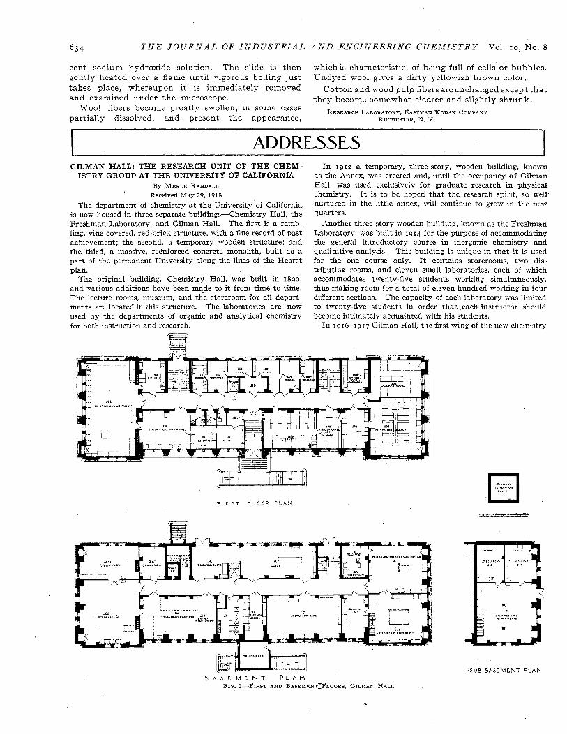
F I R 5 7 F L O O R P L A N
-lllB-s&s-
- B A S E M E N T P L A N FIG. I-FIRST AND B A S E M E N T ~ F L O O R S . GILMAN H A L L
' 5UB B A S E M E N T P L A N

Aug., 1918 T H E JOCRRNAL O F I N D U S T R I A L
building, was erected. It was named in honor of Daniel Coit Gilman, president of the University, I 872-1 8 7 5 , later president of Johns Hopkins University, under whose administration the College of Chemistry was organized. Gilman Hall is devoted exclusively to research and instruction in physical and technical chemistry.
GENERAL DESCRIPTION Gilman Hall, with a ground area of 189 by 5 7 ft., is nominally
a two-story building (Figs. I and 2 ) . There is an attic entirely finished which is lighted by large dormer windows. The base- ment is entirely above ground and under a portion ol it is the sub- basement, also above ground level. And beneath the sub- basement is a small sub-sub-basement.
The walls, floors, and roof are heavy monolithic reenforced concrete. The exterior is a cement plaster, the roof covered with red tile. Much credit is due to the architect, Mr. John Galen Howard, for the manner in which he has succeeded in combining artistic composition, permanency, and chemical usefulness.
The interior presents many features unusual in a permanent building. Every square foot of floor space is utilized Each room was planned for a specific purpose, but a t the same time every effort was made to obtain a general uniformity of equip- ment, thus admitting of change when necessary.
The interior wood trim of Oregon pine (Fig. 14) and the cement base are arranged so as not to project beyond the plaster line. Apparatus or tables can therefore be placed directly against the wall without interference.
All piping and conduits are carried exposed on the ceilings.
A N D E N G I N E E R I N G C H E M I S T R Y 63 5
In order to facilitate the future installation of additional or temporary piping or equipment, metal inserts were placed in the ceilings, and pipes in. in diameter in the neutral pla,ne of each floor beam and girder. The concrete ceilings were left un- plastered and then painted. A smooth finish was obtained by oiling the forms before the concrete was poured. Several metal sleeves with covers (Fig. 14) connect each room with those above and below. Modified picture moulds (Fig. 1 4 ) permit of fastening upon the walls without marring the plaster. Re- movable wooden panels over the transoms and between the rooms (Fig. IO) near the ceiling provide ready communication between rooms on the same floor. A complete piping system can be in- stalled to each room without cutting floors or walls.
Redwood panels (Fig. 1 1 ) are located in every room beneath the electric power switches. Two styles of lockers (Fig. 1 4 ) are used. The desk tops are, for the most part, sugar pine finished in aniline black stain. Members of the laboratory are permitted to fasten apparatus on any exposed woodwork, or to the bench tops.
Alberene stone tops have been used in the technical rooms and in the hoods (Fig. 1 6 ) . Ventilation is by individual tile flues directly to the roof. Over some spaces hanging glass ventilating hoods (Figs. 6, 8 , IO, 1 1 ) have been provided.
PIPING SYSTEM In general, the piping systems are arranged to furnish five
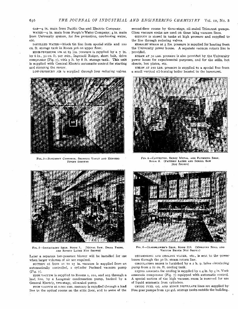
different supplies, namely, gas, low-pressure air, suction, oxygen, and water, available in each laboratory. The mains are in the basement and second floor corridors (Fig. 3 ) . The following systems are installed:
S E C O N D F L O O R PLAN
A T T I C P L A N
FIG. ?--ATTIC A N D SECOND FLOORS, GILYAN HALL
T H E J O U R N A L O F I N D U S T R I A L
GAS-4 in. main from Pacific Gas and Electric Company. WATER-4 in. main from People’s Water Company; 4 in. main
from University system, for fire protection, condensing water, etc.
DISTILLED WATER-Block tin line from special stills and IOO cu. ft. storage tank in Room 308 on upper floor.
HIGH-PRESSURE AIR a t 85 lbs. pressure is supplied by a 7 in. by 6 in., 50 cu. it. per min., Ingersoll Rolger, short belt, drive compressor (Fig. 7), with 3 f t . by 8 f t . storage tank. This unit is supplied with General Electric automatic control for starting and stopping the motor.
LOW-PRESSURE AIR is supplied through four reducing valves.
A N D E N G I N E E R I N G C H E M I S T R Y Vol. IO, No. 8
second-floor rooms by three-stage, oil-sealed Trimount pumps. Glass vacuum cocks are used on these hihg vacuum lines.
OXYGEN is stored in tanks a t high pressure and supplied t o the line through reducing valves.
EXHAUST STEAM a t 5 lbs. pressure is supplied for heating from the University power house. A separate vacuum return line is provided.
STEAM AT 30 LBS. pressure is also provided by the University power house for experimental purposes, and for the stills, hot closets, hot plates, etc.
STEAM AT 250 LBS. pressure is supplied to a special line from a small vertical oil-burning boiler located in the basement.
FIG. 8-BASEMENT CORRIDOR. SHOWING VAULT AND EXPOSED PIPING SYSTEMS
FIG. &-CARPENTER. S H E E T METAL, AND PLUWBING SHOP. ROOM 8 . (PATTERN LATHE AND SCROLL S A W
NOT SHOWN)
FIG. 5-INSTRUMENT S H O P , ROOM 7. (METAL S A W , DRILL P R E S S , AND RIVETT LATHE N O T SHOWN)
Later a separate low-pressure blower will be installed for use when larger volumes of air are required.
SUCTION a t from 2 0 t o 25 in. vacuum is supplied from an automatically controlled, 2 cylinder Packard vacuum pump
HIGH VACUUM is supplied to Rooms I , 101, and 103 through a lead line, by a Langmuir condensation pump, backed by a General Electri,c, two-stage, oil-sealed pump.
HIGH VACUUM a t 0.001 mm. mercury is supplied through a lead line to the optical rooms on the attic floor, and to some of the
(Fig. 7).
F I G . 6-GLASSBLOWER’S SHOP. ROOM 210. (MERCURY STILL AND VACUUM BENCH NOT SHOWN)
CONDENSING AND COOLING WATER, etc., is sent to the power- house through the 30 lb. steam return line.
CIRCULATING BRINE is furnished by a 2 h. p. brine circulating pump from a 7 2 cu. f t . cooling tank.
LIQUID AMMONIA for cooling is supplied by a 4 in. by 4 in. York ammonia compressor (Fig. 7) equipped with automatic control. A special section of the high vacuum room is reserved for use of liquid ammonia from cylinders.
CRUDE FUEL OIL AND STOVE DISTILLATE lines are supplied by Fess gear pumps from 150 gal. storage tanks outside the building.

Aug., 1918 T H E J O U R N A L O F I N D r S T R I A L
ELECTRIC SYSTEM
The electric system is centralized in the feeder board (Fig. 9). This board forms the partition between the electric furnace laboratory and the motor generator room. Not all the electric equipment is as yet installed.
brought to two oil switches from the University power house. IIO-ZZO VOLT, THREE-WIRE D. c. is also supplied to a 300
ampere breaker by the power house.
supplied through an oil switch from three 40 kv. amp., 2300 volt
4.000 VOLT, 60 CYCLE, 3 PHASE, STAR CONNECTED A. C. is
440 VOLT, 60 CYCLE, 3 PHASE, DELTA CONNECTED A. C. is
F I G . 7-CRYOGENIC LABORATORY. SUB-BASEMENT.
(NOTE FLOATING F O U N D A T I 3 N )
A I R COMPRESSOR,
LIQUID AIR PLANT. SUCTION PUMP, AND ICE MACHINE
FIG. ELECTRIC FURNACE LABORATORY, ROOM 19. FEEDER PANEL
AND OIL SWITCHES
transformers located in the transformer room. This is used for general power purposes. .
220 VOLT, 3 PHASE, DELTA CONNGCTED A. c. is obtained from the above transformers.
for lighting and experimental power is supplied by a 30 kv. amp., 2300 volt transformer.
SINGLE PHASE for furnace work will be supplied from a bank of three IOO kv. amp., 2 3 0 0 volt transformers. The primaries of the transformers are connected to a double throw switch so that the bank can be thrown 3 phase, star, or in parallel on a single phase. The secondary sections are brought to the board. Another set
(UNFINISHED) BEHIND WHICH ARE THE MOTOR GENERATORS
110--220 VOLT, 60 CYCLE, THREE-WIRE, SINGLE PHASE A. C.
220-440 VOLT, 60 CYCLE, 3 PHASE, DELTA CONNECTED OR
A N D E N G I N E E R I N G C H E M I S T R Y 637
of 220-440 volt primary transformers will be used for supply- ing the furnaces.
IIO VOLT D. c. is generated by a 17.5 kw. motor generator set with a Tirrill regulator. This will be used for special work.
IIO VOLT D. c. is also generated by a 12.5 kw. motor generator. 440 VOLT D. c. can be obtained by putting the above machines
in series with the 220 volt service from the university power house. 6-12 VOLT D. c. is supplied by a j kw. double commutator
machine with I IO volt field excitation.
F I G . 8-CRYOGENIC LABORATORY, UPPER PORTION, ROOMS 1 AND 3. CONTROL PANELS A N D BURDETT ELECTROLYTIC OXYGEN
HYDROGEN GENERATORS
FIG. 10-TECHNICAL ELECTROCHEMICAL LABORATORY, ROOM 119. MAIN DISTRIBUTION BOARD
12-24 VOLT D. c. will be supplied for furnace work by a 5 0 kw. double commutator machine.
A IOO CELL EDISON STORAGE BATTERY will be installed behind the left end of the feeder panel.
By means of the distributing system any voltage on the feeder board or in any part of the building is available on any other board. The fields of the generators can be controlled from any room. Only heavy currents are taken directly from the feeder panel.
The main distribution board (Fig. IO) is in Room 119 directly above the feeder board. From the fuses on this board 17 No. 6 wires run to each of the 6 distribution boards. (Right-hand portion of board, Fig. IO>) From the fuses on the distributing

6 3 8 T H E J O U R N A L O F I N D U S T R I A L A N D E N G I N E E R I N G CHEMISTRE‘ Vol. IO, KO. 8
F I G . 1 I-FURNACE L A B O R A T O R Y , ROOM 19. HERRESHOFF ROASTING FURNACE ON THE RIGHT
board 7 No. 8 wires run to each of the room panels (Fig. IO), from which two 2-wire, 60 ampere and one 3-wire circuit can be used a t the same time. Ordinary 1 1 0 volt A . c. and D. c. may be brought to the switches on the room panels by means of fuses alone, but by moving these fuses to other positions and using flexible leads, any other circuit may be connected to these switches. By paralleling the circuits 180 amperes of a single kind of current may be brought to the room panel. Means of locking the fuses and plugs on the distribution board are provided.
All machinery is individual motor-driven by 440 volt, 3 phase, A. c. motors, except the machines in the instrument and glass-blowing shops which are driven by 2 2 0 volt D. c. motors.
SHOPS
Probably the most important feature of the laboratory is the shops. Each of these is in charge of a full-time mechanic with occasianal assistance. These shops exist for the primary purpose of constructing research apparatus and for aiding the research men of this department.
islequipped with a Wells pattern lathe, a Greenlee tilting saw table with boring and mortising attachments, a Porter 6 in. jointer, a Beach tilting table scroll saw, a 32 in. band saw, sheet metal working tools, and a complete line of fittings and tools for pipe as large as z in. in diameter.
The CARPENTER, SHEET METAL, AND PLUMBING SHOP (Fig. 4)
FIG 12-MAIN TECHNICAL LABORATORY, ROOM 121. PIPING SYSTEMS
AND S U S P B N D E D BALCONY
The INSTRUMENT SHOP (Fig. 5) has an 8 in. Rivett lathe com- plete, an 8 in. Stark lathe, a 12 in. Seneca Falls lathe, a Robbins and Myers buffer and grinder, a Cincinnati universaI tool grinder, a Browne and Sharpe ZA milling machine, a 20 in. Barnes drill, a Sigourney sensitive drill, a Canedy-Otto drill, a Grabo metal saw table, an oxyhydrogen welding equipment, a 2 ton travelling Peerless hoist, and a large number of small tools and stock. A 14 in. Hendey lathe and a 20 in. Lodge and Shipley lathe are contemplated.
The GLASS-BLOWER’S SHOP (Fig. 6) has various blow torches for glass and quartz and machines for grinding and polishing. In an adjaining room is a very complete stock of stopcocks, and about 3000 lbs. stock of soda, lead, pyrex and quartz glass tubing of all sizes.
THE STUDENTS mop-Members of the laboratory do not, except in special cases with the permission of the mechanics in charge, use the above shops. They may, however, make free use of the students’ shop, Room 20, which is equipped with a limited amount of machinery and hand tools.
LIBRARY, STUDIES, ETC.
The University fortunately possesses a very complete library, and a large number of the books relating to chemistry are shelved in the CHEMISTRY DEPARTMENT LIBRARY, Room 109. Books may be taken, without formality, to the library annex, Room 105,
FIG. 13-sEhllINAR ROGM FIG, 14-OFFICE AND RESEARCH LABORATORY, R O O M 103. VACUUM
BENCH ON THE LERT

Aug., 1918 T H E J O U R N A L OF I N D U S T R I A L A N D E N G I N E E R I N G C H E M I S T R Y 639
where there are tables and blackboards, and where violent and heated scientific discussions may take place without disturbing the readers. A study for the men, Room 3 2 0 , and one for the women, Room 3 0 2 , are also provided.
The SEMINAR ROOM (Fig. 13) is arranged for small discussions or faculty meetings around the central table, but its capacity may be increased to about 60 people without losing much of the congenial atmosphere of the small seminar. Discussion is encouraged by easy access to blackboards which line the walls of the room.
space and facilities for research a t low temperatures are pro- vided.
The POTENTIOMETER AND CALORIMETER LABORATORY (Fig. I 5 ) adjoins the cryogenic laboratory and contains large oil thermo- stats and suitable high-resistance potentiometers permanently installed for the measurement of electrode potentials. A potentiometer sensitive to o.ooo,ooo,o~ volt and free from parasitic e. m. f.'s., and several 50-junction thermo-elements and twin calorimeters are in use. A second potentiometer of like characteristics is being installed.
COLD Roox-Certain experiments cannot be carried out in the open air since the temperature in Berkeley is never below freezing. One-half of one of the small research rooms in the basement (Room 4) is therefore used as an ice box and provided with direct ammonia expansion coils. A standard laboratory desk and the usual laboratory piping and electrical service, with the exception of water, are available.
The HIGH VACUUM LABORATORY, Room 101, is provided with a series of 8 low benches, 6 ft. long, 18 in. wide and 18 in. high, a t the back of which is a framework of '/z in. steel rods upon which complicated glass apparatus may be conveniently mounted (Fig. 14). These benches are arranged end-on on each side of a central bench upon which is the usual laboratory piping and, in addition, 0.001 mm. of mercury vacuum.
The PHYSICAL CHEMICAL LABORATORY (Fig. 16) has space for 4 2 students.
A SPECIAL RESEARCH LABORATORY (Room 205) is provided for seniors doing advanced physical chemistry and researches which do not require large complicated apparatus.
A large number of small rooms are devoted to special purposes.
Five thermostats will be installed in this room,
Of these the polariscope room, No. 303, the spectrophotometer room, No. 305, the conductivity room, No. 311, and the high FIG. 1 ~--POTENTIOM@TER AND CALORIMETER LABORATORY. ROOM 2
A small LECTURE ROOM, Room 219, with seats for 60 people, frequency conductivity room, No. 313, deserve special mention. is used for the courses in advanced physical and technical A separate, well ventilated room, No. 316, is provided for work chemistry. involving dangerous or unpleasant gases. Metallographic and
The DRAFTING ROOM, Room 304, is equipped with cross-sec- photochemical laboratories, Rooms 3 2 2 and 301, are being tion paper, drawing tables, and instruments. A glass top equipped. There are two large dark rooms. A 60 ft. optical table illuminated from below is a special feature. path is available in Rooms 303-313.
THE LABORATORIES
CONSTANT TEMPERATURE ROOM-~A pit 14 ft. by 14 f t . and I O
f t . in depth is located under a portion of the sub-basement. A trap door in the ceiling and traps in the various floors above provide Cor a clear height of about 7 0 f t . for experimental pur- poses. The walls are heavily reenforced so that dangerous apparatus may be operated in this room. Since the room is underground and there is no access to it except through the trap in the ceiling very uniform temperatures can be maintained.
The CRYOGENIC OR LOW-TEMPERATURE LABORATORY (Figs. 7 and 8) occupies the sub-basement and Rooms I and 3 of the basement. The compressors and heavy moving machinery rest upon a floating foundation. This foundation consists of a IO-
in. slab of reenlorced concrete floating on 6 in. of dry sand and isolated from the rest of the building by a 2 in. sand joint (see foreground Fig. 7) . With all the machinery in motion the laboratories are so completely free from vibration that the most sensitive galvanometers may be mounted directly on the walls (Fig. 15). The motor generator sets, Room 15, are mounted on a similar floating foundation.
The liquid air plant a t present consists of a new 20 h. p., 4 stage, Norwalk compressor and Erin liquefier. A modern, FIG. 16-PHYSICAL CHEMISTRY, ROOM 202, FOR JUNIORS. THERMOSTATS high-efficiency, liquid air plant is planned for this laboratory and the present compressor will be used for the production of liquid For the most part offices and private research laboratories hydrogen. A liquid helium plant is also planned. TWO standard There are a large number of these, Room commercial units of Burdett electrolytic oxygen-hydrogen 103 (Fig. 14) being a typical example. generators for the production of pure gases are installed. The The ANALYSIS ROOM, No. 2 0 9 , is equipped as a general analytical liquefiers are on the floor above the compressors, which are laboratory with electrolytic bench and other analytical con- visible through a IO f t . by I O ft. opening in the floor. Ample veniences. I t is not intended for instruction, and i t is,probable
AND RELAYS A R ~ N O T YET INSTALLED
have been combined.

640 T H E J O U R N A L OF I N D U S T R I A L
that a full-time analyst will be put in charge, who will do routine analysis connected with the various researches, prepare solutions, etc.
Small BALANCE ROOMS which can be kept free from moisture, carbon dioxide, etc., open off the analysis room.
The COMBUSTION LABORATORY, Room 2 13, adjoins the analysis room. It is equipped with organic and carbon combustion trains, multiple unit electric tube, crucible, and muffle furnaces.
The ORGANIC LABORATORY, Room 222, is fitted with a Kjel- dah1 rack, thermostats, and the general equipment of an organic laboratory. This laboratory is not connected with the organic department but is for the convenience of those who need to do organic synthesis, etc., incidental to theoretical and technical researches.
TECHNICAL LABORATORIES
The TECHNICAL LABORATORIES, Rooms 21, 2 2 , 121, and 221,
form in effect a four-story factory. The upper room is equipped for the analytical control of technical operations, the factory laboratory, and a part of the room is reserved for large apparatus. The main room (Fig. 12) contains a steam table, a drying closet, a large shelf dryer, 8 in. and 15 in. International basket centri- fuges, a large International centrifuge, two 250-lb., jo-ga!. jacketed autoclaves, two 2-gal. autoclaves, combination column still, extractor, condensers, etc., Kestner type evaporator, a 500-gal. tank, 5-gal. and 25-gal. jacketed cast iron kettles with extension pieces and covers. The kettles may be combined to make such pieces as vacuum pans, vacuufn agitators, vacuum crystallizing evaporators with or without agitation, nitrators, sulfonators, etc. This equipment is being added to very rapidly.
The heavy technical rooms, Nos. 21 and 22, contain a steam boiler, a cement kiln, a suction filter, a filter press and grind- ing machinery.
The ELECTROCHEMICAL LABORATORY has been already partly described. Operations are worked out on a small scale in Room 119 (Fig. IO), and on a larger scale in Room 19 (Fig. 9). This room is provided with a traveling 2-ton Peerless hoist. A large stock of electrodes, refractories, and materials for furnace con- struction are carried in Room 11. The steel has been omitted from the floor in order to diminish eddy current losses. The furnace laboratory houses several gas and oil furnaces and a Herreshoff mechanical pyrites burner with six 24-in. hearths.
STORES Stores are distributed from Rooms 214 and 216. Only a
small number of instruments of general use are here. Most of the apparatus is stored in apparatus closets built in the labora- tory in which it is most often used. A large room, No. 32 I, is pro- vided for large set-ups temporarily out of use. All apparatus and stores are catalogued by the number of the room, a section letter, and shelf number. This number appears on the ap- paratus, and a tag giving the temporary location is left in the permanent location when the instruments, etc., are in use. It is the policy of the laboratory t o keep all apparatus in use, and easily available day or night.
In this brief outline only those features which are unique in laboratory construction and equipment have been described. The accompanying photographs are designed to show certain of the rooms as they appear under actual working conditions.
UNIVERSITY OF CALIFORNIA BERKELEY
DYEING OF KHAKI IN THE UNITED STATES' HISTORICAL AND THEORETICAL
By JOHN C. HBBDEN The khaki-dyed fabrics are used almost wholly for military
purposes. The use of this color for uniforms had its origin in the Boer War. The peculiar shade of the terrain of South
1 Address delivered before the New York Section, Society of Chemical Industry, May 24, 1918.
A N D E N G I N E E R I N G C H E M I S T R Y Vol. IO, No. 8
Africa made it possible to conceal the presence of troops from the enemy by adopting a shade for uniforms which blended with the color of the landscape. Military observers, noting the effect of the use of this kind of uniform, gave their attention to its de- velopment in other countries.
The history of the dyeing of khaki is spread through the literature, and really originates in the first patents taken out by Gatty in Great Britain in 1884. It was not, however, until 1897 that the development of this color was taken up seriously. The British dye houses then began to give particular attention to the production of this color, both on cotton and wool.
At about the year 1900 the American Government took up the use of khaki-colored fabrics for the manufacture of tents, kits, and uniforms. From that time there has been a steady development in the improvement of both the shade and quality of the fabrics. The early shades of khaki used by the American Government were comparatively light and of a greenish yellow tone. This shade was changed to a darker and more yellow brownish khaki. As the German field gray came into use, our Government adopted what is now known as the olive-drab. At the present time the three shades of khaki seem to be in use.
When the use of khaki was taken up by the American Army, our soldiers were clothed in uniforms made from woolen fabrics. Although the quality of the wool used was the best, such fabrics, in order to have strength, were of necessity heavy. Mr. T. B. Owen, between the years 1900 and 1902, while he was acting as superintendent of the Atlantic Mills in Providence, R. I., called to the attention of the Quartermaster's Department the supe- riority of worsted fabrics or worsted serges, particularly for the manufacture of blouses and shirts. These fabrics were tried by the Army and found to be superior to the woolen fabrics. To-day there is scarcely any woolen fabric used, except for blankets and overcoats.
The production of a khaki shade on silk is required so infrequently that methods for producing this color on this fiber need not be discussed.
The dyeing of khaki both on cotton and wool may be classed under the following methods:
I-Chemical or oxidation methods for both cotton and wool. 2-Mordant dyeing methods, particularly for dyeing wool, 3-After-chroming methods, or one-bath chrome methods,
4-Direct or substantive dye methods, with or without after-
S S u l f u r color dyeing methods for cotton. 6-Vat color dyeing methods for cotton. The chemical or oxidation method generally used for dyeing
cotton cloths or yarns for khaki-colored fabrics, for use in uni- forms, tents, and kits, is based upon the production in and on the fiber of a mixture of the oxides of iron and chromium. Before the shades thus produced were used for military purposes particularly, these dyes were usually designated as iron buffs. The browns produced by the use of salts of manganese, usually called manganese bister, are too deep and too red to be used as khaki shades or as the basis for khaki colors.
In the production of khaki by this method, the cloth is padded or saturated with a mixture of iron and chromium salts, and then, either with or without ageing, is passed into a solution of an alkali in order to precipitate the mixture of iron and chromium oxides in and on the fiber. An alternative method is to pad or saturate the cloth, dry a t a low temperature, age in an ageing machine, and then pass into a solution of alkali in order to precipitate the oxides and produce the khaki color on the fiber. In the padding or precipitating method, when the padded or saturated goods are not dried, it is necessary to make several passages of the fabric through the solutions of the salts of iron and chromium, and through the alkaline solution. When the method in which the cloth is padded, dried, and aged before
Khaki is usually dyed on cotton or wool.
for wool.
treatment, particularly for cotton, but also applicable to wool.