gillette madison pipeline project
TRANSCRIPT

Pre Design Report on the
Gillette Madison Pipeline Project FINAL SUBMITTAL
for the
City of Gillette, Wyoming
Wyoming Water Development Commission
November 22, 2010
BMcD Project No. 54432 MMI Project No. 4776.001
Pre Design Report
Gillette Madison Pipeline Project
prepared for
City of Gillette, Wyoming Wyoming Water Development Commission
November 22, 2010 BMcD Project No. 54432 MMI Project No 4776.001
prepared by
Burns & McDonnell Engineering Company, Inc. Centennial, Colorado
Morrison Maierle, Inc.
Billings Montana Gillette Wyoming

Gillette Madison Pipeline Project Table of Contents Pre Design Report November 22, 2010
TOC-1
TABLE OF CONTENTS
Page No.
1.0 OVERVIEW OF PROJECT ............................................................................................... 1
2.0 SCOPE OF THE PRE DESIGN REPORT ........................................................................ 2
3.0 TECHNICAL MEMORANDUMS ..................................................................................... 11
3.1 TM 1 - GMPP In-Town Piping Route ........................................................................................ 11
3.2 TM 2 – GMPP Test Wells for Madison Well Field Expansion .............................................. 15
3.3 TM 3 – Population Projections, demands and source of supply requirements ................. 18
3.4 TM 4 – GMPP New Well Field Pumping Alternatives ............................................................ 20
3.5 TM 5 – Water Quality and Blending Strategies ...................................................................... 22
3.6 TM 6 – Determination of Storage Requirements .................................................................... 32
3.7 TM 7 – Hydraulic Modeling ........................................................................................................ 38
3.8 TM 8 – 10% Tranmission Pipeline Alignment and Hydraulic Analysis ................................ 42
3.9 TM 9 – Plan for Regional Water Supply .................................................................................. 46
3.10 TM 10 – Pipeline Material Evaluation and Recommendations ............................................ 49
3.11 TM 11 – Draft Construction Schedule and Phasing (with Consideration for Potential
Funding) ........................................................................................................................................ 54
3.12 TM 12 – Water System Condtion/Operational Review .......................................................... 58
3.13 TM 13 – Evaluation of Disinfection Alternatives ..................................................................... 59
4.0 SUMMARY ...................................................................................................................... 64
APPENDIX A – FINALIZED TECHNICAL MEMORANDUMS APPENDIX B – ENGINEERS OPINION OF PROBABLE COST ESTIMATES
* * * * *

Gillette Madison Pipeline Project Overview of Project Pre Design Report November 22, 2010
1
1.0 OVERVIEW OF PROJECT
The City of Gillette (COG), Wyoming is experiencing aggressive population growth due to the
energy development in Wyoming, especially in Campbell County. This growth is expected to
continue in the future and has resulted in increased water demands. Currently during peak
periods of usage, these increased demands are taxing Gillette’s existing water supplies. This
problem is expected to worsen with the future growth.
On January 17, 2007, the COG authorized Morrison-Maierle, and Burns and McDonnell
Engineering Company Inc. to proceed with the preparation of the Long Term Water Supply,
Level II Study. This study generally consisted of identifying and analyzing new water sources
for the COG to supplement their existing water supply in order to meet future demands.
Based on the evaluation of all factors, it was concluded in the Level II study that use of the
Madison formation as the source for additional water is the preferred alternative to meet the
COG’s long term water supply needs. Use of this source would require design and construction
of the necessary wells, piping, treatment and pumping facilities.
On July 30, 2009 the COG authorized Burns & McDonnell and Morrison-Maierle to provide the
design for the Gillette Regional Water Supply Project currently referred to as the Gillette
Madison Pipeline Project (GMPP). The original agreement with the City of Gillette anticipated
that the following facilities would be designed:
• Wells at the Madison Formation
• Well Field Piping
• Water Transmission Pipelines
• Pump Station(s)
• Storage Reservoir

Gillette Madison Pipeline Project Overview of Project Pre Design Report November 22, 2010
2
• In-Town Piping
Prior to beginning the design for the GMPP facilities development of a pre-design report was
required. The general purpose of the pre-design report is to better define the facilities that will
be required to utilize the Madison formation water source, set the parameters to be used as the
basis of the designs for these facilities, and to identify any further facilities that will be required.
2.0 SCOPE OF THE PRE DESIGN REPORT
Part 1 – Basic Services of the Contract includes paragraph A.1.02 Preliminary Design Phase.
This paragraph makes reference to Appendix 1 to EXHIBIT A. Appendix 1 outlines the Scope
of Services for both the Preliminary and Design Phases of the project. Following is the excerpt
from the Scope for the Preliminary Phase as outlined in Appendix 1.

Gillette Madison Pipeline Project Scope of the Pre Design Report Final Pre Design Report November 22, 2010
3
C. Preliminary Phase 1. Under the Preliminary Phase, the Engineer agrees to provide the following: (1) A report
on the Madison Formation, (2) A Water System Plan for the regional water system, (3) A Pre-design Report for the facilities needed to import water from a well field tapping the Madison Formation, (4) A Project Management Manual, and (5) Field Surveys, Photogrammetric Surveys, and Legal Descriptions. Specifically, the Engineer shall perform the following services:
a. Report on Madison Formation Wells. 1) Review the Madison formation well recommendations in the Morrison-
Maierle’s 2007 Long Term Water Supply, Level II Report and existing Madison formation wells including: drilling, test data, and water quality. Provide a Technical Memorandum with recommendations for the test well(s) size, location, and discuss design considerations of the project test well (strata wells).
2) Sample and analyze water from existing wells tapping the Madison Formation, if needed, and from the wells drilled as part of this project. (Later removed from the Scope by pending contract amendment)
3) Determine the number of wells that will be required in the new well field area.
4) The Engineer shall recommend to Owner if the well(s) to be drilled under this phase of the project should be a test well, a production well or a series of stratigraphic holes. The recommendation will include cost comparisons for each alternative considered.
5) The Engineer shall provide bidding/contract documents to drill and test the new well into the Madison Formation as approved by the OWNER. Work associated with the test well includes:
a) Provide ten (10) sets of contract documents for 10%, 50%, 90% contract document reviews and final contract documents. The Engineer should include costs to attend all review meetings in Gillette.
b) Provide necessary legal surveys and descriptions for land and easement necessary to permit and complete the well. The OWNER will be responsible for negotiating well easements with the landowners.
c) Prepare permits and applications to the State Engineer’s Office and the Wyoming Department of Environmental Quality. Engineer will include contract language making NPDES permitting the responsibility of the Contractor. Any actual permit fees will be the responsibility of the Owner.
d) Conduct a pre-bid meeting, address bidders questions and comments, assist the Owner with the bid opening, and provide an award recommendation to the Owner.
e) Provide construction management services normally associated with construction administration including; RPR services, issuing change orders, field orders, reviewing contractor pay request, etc.

Gillette Madison Pipeline Project Scope of the Pre Design Report Final Pre Design Report November 22, 2010
4
f) This scope includes the design and construction phase engineering services for the permanent well house for one (1) test well and the design phase services for the permanent well houses for five (5) production wells.
g) This scope assumes well completion to similar depths as the adjoining existing Madison field. Any substantial increases in depth requiring more time on site by the Engineer is not included in this scope.
h) Conduct a pre-construction conference including the Contractor, City of Gillette, WWDC, and any other key stakeholder and record minutes of the conference.
i) Collect and send water samples to the laboratory. The price for one complete battery of analytical tests for each well as shown below is included in this scope. Any further water quality testing is not included in this scope.
j) The hydrogeologist will: i. Provide on-site support during drilling.
ii. Review and process the drift and alignment survey of the hole.
iii. Oversee and interpret down-hole geophysical logs of the hole. This shall include gamma logs, Gamma-gamma and Neutron Density logs, Resistivity logs, Spontaneous Potential and Differential temperature logs, and a Caliper log, as appropriate.
iv. Select water bearing zones. v. Finalize the screen design and filter pack design.
vi. Specify well development techniques. vii. Supervise pumping tests to include a stepped rate test, a
24 hour constant rate test, and develop a spinner log. viii. Sample the groundwater for analytical chemistry tests.
k) Prepare a draft report of the well construction, development testing, and disinfection for each well.
l) Finalize design of down-hole pumping equipment and electrical systems, if well is to be made into a production well.
m) Provide full-time RPR services and construction administration services for the installation of permanent pump equipment, electrical systems, and connection of wells to the existing collection system if well is to be made into a production well.
n) Provide a final report detailing well construction, development, and disinfection after receiving owner and/or regulatory comments on draft report.
o) Provide two hard copies (11”x17” Mylar) and one electronic copy of record drawings and Certificates of Survey of all well construction.
p) Finalize WDEQ and SEO permits (including final reports) for each well.
6) Coordinate and manage work done by Engineer’s subcontractors.

Gillette Madison Pipeline Project Scope of the Pre Design Report Final Pre Design Report November 22, 2010
5
7) Prepare report summarizing work done in the well field, giving cost estimates for future wells, evaluating the aquifer; determine well spacing, and discussing anticipated well-field behavior. Ten (10) copies of this report shall be furnished to the OWNER.
b. Water System Plan. 1) Review reports (2007 Long Term Water Supply, Level II Report, and
2009 Gillette Regional Master Plan Level I Report), correspondence, test data, maps, drawings, records, operational data, and planning documents pertinent to the Owner’s water system.
2) Meet with the Owner’s staff to discuss condition and operation of the Owner’s water system.
3) The Owner, in consultation with Campbell County and the WWDC, will determine the future service area boundaries for the project. Land use issues will be developed in close cooperation with the Owner’s staff.
4) The existing and future water requirements within the corporate limits of the Owner, the comprehensive planning boundary, and service area boundary in c. above based on production records, land use, and water duties, including average day, maximum day, peak hour, and fire flow demands shall be provided to the Engineer by the Owner without independent verification by the Engineer.
5) Determine storage requirement for the Gillette Madison Pipeline Project. 6) Conduct computer analyses of the Owner’s existing major water system
facilities and the proposed water system within the Owner’s future service area for peak hour and maximum day plus fire flow conditions, surge analysis and mass-balance type water quality analysis showing the effects of blending strategies. The Engineer will only conduct computer analyses necessary to verify one (1) recommended in-town piping size and one (1) alignment provided by the Owner via the 2009 Gillette Regional Master Plan Level I Report. The computer analyses will not include modeling of alternative piping configurations and alignments for the north/south transmission piping. If the verification indicates that the Owner’s recommended in-town piping size and alignment do not meet the water transmission requirements, additional computer analyses shall be considered additional professional services.
7) Evaluate second Madison Booster Pump Station versus additional Madison Formation well hydraulic capacity and provide recommendation
c. Pre-design Report for Importation of Madison Well Water, including appurtenant water system facilities.
1) Review reports (2007 Long Term Water Supply, Level II Report, 2009 Gillette Regional Water Supply Level I Report), other reports of water systems within the regional system, correspondence, test data, maps, drawings, records, and planning documents pertaining to the Gillette Madison Pipeline Project.
2) Determine final pipeline alignment and diameters and prepare preliminary plans and specification outline for the pipeline between the Madison Formation well field and the terminal reservoir in Gillette. In

Gillette Madison Pipeline Project Scope of the Pre Design Report Final Pre Design Report November 22, 2010
6
determining pipeline alignment and diameters, consideration shall be given to supply water to areas identified in the 2009 Gillette Regional Master Plan Level I Report.
3) In close coordination with the Owner’s staff, select the recommended plan for the Gillette Madison Pipeline Project including pipeline alignments and sizes, locations and types of wells, connecting pipelines to the wells and regional water system, water booster pump station, and storage facilities.
4) Evaluate different pipeline materials and provide recommendations. Minimally, the analysis should include consideration of surge effects, construction techniques, contractor experience, cathodic protection requirements, recommended fitting types, and estimated installed cost per foot.
5) Prepare a detailed draft construct schedule including any proposals to phase project construction. Obtain input from the Owner and WWDC before including the schedule in the Pre-Design Report.
6) Prepare a draft Pre-design Report containing basic criteria, preliminary sketches, maps, and preliminary estimates of capital cost and operations and maintenance cost for the regional water system. Ten (10) copies of the draft Pre-design Report shall be furnished to the Owner.
7) Meet with Owner, regional water users, and WWDC to review draft Pre-Design Report comments.
8) Incorporate final comments in the final Pre-Design Report. Prepare and deliver ten (10) copies of the final Pre-Design Report to the Owner.
9) Obtain all necessary permits and variances including, but not limited to, Wyoming Department of Environmental Quality, Wyoming Department of Transportation, Crook County, and Campbell County. Provide an outline of the requirements to secure those permits and licenses.
10) Conduct necessary environmental, cultural resources, wetland, and threatened and endangered species assessments of the project and prepare report(s) of findings, conclusions, and recommendations. This task includes required surveying and mapping necessary for reports.
11) The Engineer shall participate in three public outreach meetings during the pre-design phase.
d. Project Management Manual. 1) Prepare Project Management Manual consisting of procurement and
contracting strategy, project budget (including operations and maintenance costs), cash flow requirements, project schedule, project organization chart, and division of responsibilities. Ten (10) copies of the Project Management Manual shall be furnished to the Owner.
e. Field Surveys, Photogrammetric Surveys, Mapping, Legal Descriptions, and Permitting.
1) Establish horizontal and vertical ground control and make photogrammetric surveys of the pipeline alignment and of the locations of the other facilities after their locations have been approved by the OWNER. The photogrammetric survey shall be done with one foot (1’) contour interval.

Gillette Madison Pipeline Project Scope of the Pre Design Report Final Pre Design Report November 22, 2010
7
2) Locate by field survey methods property lines where they cross the pipeline right-of-way, if said pipeline right-of-way is outside existing rights-of-ways, and locate property lines at sites of other facilities.
3) Develop a methodology acceptable to affected entities for legal descriptions, surveys, and other information required for easements or parcels to be occupied for the entire project. Engineer to provide description of methodology in a letter report.
4) Following Owner approval of survey methodology, conduct necessary surveys to design the collection and transmission pipeline, pumping stations, storage tanks, necessary for the project including preparation of all necessary easement descriptions and exhibits.
5) Coordinate the use of Wyoming Department of Transportation and Crook County right-of-ways as necessary for the pipeline alignment.
6) Prepare ownership information, legal descriptions and maps for procurement of right-of-way and property to be obtained. This task is based on 180 parcels of land. Of these 180 parcels of land, 45 parcels were assumed to be “Easy” and 135 parcels were assumed to be “Moderate.” The following definitions of Easy, Moderate, and Hard parcels to develop easements for were used to scope the project:
a) Easy: Well defined legal descriptions with good ties. b) Moderate: Legal descriptions with minor ambiguities. c) Hard: Legal descriptions with ambiguities and/or bad or no ties
to existing public land system. d) This scope assumes no “Hard” parcels. Parcels that qualify as
“Hard” based on the level of effort described above are outside the scope of this work and subject to additional compensation as outlined in Appendix A, Section A.2.01.
7) Prepare maps showing surface topography and utilities along the selected pipeline alignment and at the well field, reservoir sites, and water booster pump station site.
8) Investigate location of existing utilities, surface and subsurface structures, and proposed future improvements of other agencies along and adjacent to the transmission pipeline and other facilities.
9) Determine actual depths of interfering utilities by field verification. 10) Deliver to the Owner following completion of construction, all aerial
photographic models make for this project. 11) Prepare the application and any required supporting information for the
required permits and licenses necessary to complete the project. 12) Coordinate and manage work done by ENGINEER subcontractors.

Gillette Madison Pipeline Project Scope of the Pre Design Report Final Pre Design Report November 22, 2010
8
Upon entering the preliminary phase it was determined that much of the preliminary scope of
work could most efficiently be completed through development of a series of Technical
Memorandums (TM) covering specific topics. This would provide a format for each topic to be
covered independently and in sufficient detail, as various pieces of necessary information were
obtained and developed. It would also allow for efficient review and comment by all parties.
The COG and Wyoming Water Development Commission (WWDC) agreed with this
methodology. Once the TM’s were finalized, they were reviewed by the COG and WWDC and
a special Technical Memorandum meeting was held to discuss the review comments. The TM’s
were then finalized and used to develop the Preliminary Design Report.
The following table list the titles of the technical memorandums and identifies which portion of
the scope of services, listed above, are covered in each. The scope items which are not covered
by a specific TM are being completed under separate submittal shown on the following page.
TM # Technical Memorandum Title Scope Item(s) Covered = Scope Items completed as included in the TM
TM-1 GMPP In-Town Piping Route C.1.c.2), C.1.c.3) TM-2 GMPP Test Wells for Madison Well Field
Expansion C.1.a.1), C.1.a.3), C.1.a.4), C.1.c.3)
TM-3 Population Projections, Demands and Source of Supply Requirements
C.1.b.1), C.1.b.4), C.1.c.1)
TM-4 GMPP New Well Field Pumping Alternatives
C.1.b.7), C.1.c.3)
TM-5 Water Quality and Blending Strategies C.1.c.3) TM-6 Determination of Storage Requirements C.1.b.5), C.1.c.3) TM-7 Hydraulic analyses C.1.b.6) TM-8 10% Transmission Pipeline Alignment and
Hydraulic Analysis C.1.c.2), C.1.c.3)
TM-9 Plan for Regional Water Supply C.1.b.3), C.1.b.4), C.1.c.1), C.1.c.3) TM-10 Pipeline Material Evaluation and
Recommendations C.1.c.4)
TM-11 Draft Construction Schedule and Phasing C.1.c.5) TM-12 Water System Condition/Operational Review C.1.b.2) TM-13 Evaluation of Disinfection Alternatives This is a change from scope based on
the COG’s preference for use of on-site sodium hypochlorite generation.

Gillette Madison Pipeline Project Scope of the Pre Design Report Final Pre Design Report November 22, 2010
9
Preliminary Scope Items Under Separate Submittal Item and Submittal Schedule Scope Item(s) Covered Test Well Drilling Contract Documents/Bidding
• Final Drawings and Specification delivery scheduled for September 10, 2010
• Pre-Bid meeting/Award Recommendation scheduled for September 2010
• Construction management services scheduled for Sept – Dec 2010
• Conduct Preconstruction conference scheduled for September 2010
• Hydrogeologist services scheduled for Sept – Dec 2010
• Draft and Final report on test well scheduled January 2011
C.1.a.5) a), b), c), f)
d)
e), f), i)
h)
j), i-viii
k), n)
Report summarizing • Well field work • Cost estimates for future wells • Aquifer evaluations • Well spacing • Anticipated well behavior
C.1.a.7)
Prepare draft Pre-Design Report (This Report) This document
C.1.c.6)
Draft pre-design report meeting with COG/WWDC August 2010
C.1.c.7)
Finalize pre-design report September 2010
C.1.c.8)
Necessary Permits and Variances • To be performed as 50% and 90% designs
proceed and information is available that is necessary for submittals.
C.1.c.9)
Environmental Assessments • Currently underway and to be completed as
50% and 90% designs proceed and final alignments are set.
schedule for June 2010 – Dec 2010.
C.1.c.10)
Public Outreach Meetings • August 23, 2010
C.1.c.11)

Gillette Madison Pipeline Project Scope of the Pre Design Report Final Pre Design Report November 22, 2010
10
Preliminary Scope Items Under Separate Submittal (cont.) Item and Submittal Schedule Scope Item(s) Covered Project Management Manual
• Version 2 of this document was prepared and presented to the COG and WWDC on 12/16/10. Currently the document covers project organization, division of responsibilities and various protocols for the project. As the project proceeds and necessary information is available the Manual will be updated to cover, procurement and contracting strategies, project budgets, and cash flow requirements.
C.1.d.
Field surveys, photogrammetric surveys, mapping, legal descriptions, and permitting
• Field surveys, photogrammetric surveys and mapping have now been complete.
• Legal description and permitting are ongoing.
C.1.e.
* * * * *
Gillette Madison Pipeline Project Technical Memorandums Pre Design Report November 22, 2010
11
3.0 TECHNICAL MEMORANDUMS
Drafts of the Technical Memorandums listed in Section 2.0 were prepared and submitted to the
COG and WWDC on April 30, 2010. On May 11, 2010 a special meeting was held at the City
of Gillette (COG) offices to review questions and comments from the COG and WWDC staffs.
The Technical Memorandums were then finalized to create this Pre-Design report. Copies of the
final Technical Memorandums are included in Appendix A. This section provides a brief
description of the purpose of each of the Technical Memorandums and the conclusions and
recommendations derived from each.
3.1 TM 1 - GMPP IN-TOWN PIPING ROUTE
DESCRIPTION
This Technical Memorandum evaluates options for the design of the in-town piping routes. The
new water supply from the Madison formation will be delivered into the Zone I – Reservoir IV
(Z1- R4) Tank off of Southern Drive. The main goal of the in-town piping is to hydraulically tie
tank Z1-R4 to the Zone I – Reservoir III (Z1-R3) tank which is just off of Westover Road and
commonly referred to as the Dump Hill tank. The TM evaluates six alternative routes between
the two tanks discussing the pros and cons of each. The main factors considered in the analysis
include:
• Hydraulics –the memorandum considers potential hydraulic interferences that would be
created by each routes resulting pipe elevation based on its relation to the operating levels in
the Z1-R4 and Z1-R3 tanks.
• Zone 1 – Reservoir 5 (Z1-R5) and service to West Gillette – the potential of each route to
connect to the Z1-R5 Tank and provide future service to the West Gillette development
areas.

Gillette Madison Pipeline Project Technical Memorandums Pre Design Report November 22, 2010
12
• WYDOT Facility Avoidance – the COG would like to avoid recently constructed WYDOT
roadways such as Burma Road as well as planned WYDOT construction in Highway 50,
between Westover Road and Lakeway Road.
The descriptions and the length of associated pipe for the six alternative routes evaluated in
the Technical Memorandum are indicated in the table on the following page.
RECOMMENDATIONS & CONCLUSIONS
During development of this Technical Memorandum there was much discussion on the ongoing
WYDOT Highway 50 roadway project that will soon be constructed between Westover Road
and Lakeway Road. A specific concern was the timing of the transmission line construction
through this area should a route with this alignment be selected. It was concluded by WYDOT
and the COG that a design for the transmission line section along Highway 50 between Westover
Road and Lakeway Road would be prepared by WYDOT’s engineering consultant. This would
allow for construction of this section of transmission line to be installed with the highway
improvements thereby eliminating future disruptions to the new Highway 50 construction.
Based on the evaluations of the pros and cons of each of the alternative in-town waterline routes,
Technical Memorandum 1 provides the following conclusions and recommendations:
• The viable alternate alignments are #1, #3 and #5
• The recommended alternate route to be designed is Route 3 based on the following:
Route 3 does not have any major obstructions or grade conflicts.
Route 3 will be almost completely looped to reservoir Z1-R5
Based on the fact that WYDOT will now be constructing the section of the
transmission line between Westover Road and Lakeway Road, additional
easements will no longer be required through this area to avoid the highway
construction.

Gillette Madison Pipeline Project Technical Memorandums Pre Design Report November 22, 2010
13
Route
Alignment Description
Pros
Cons
Length
(feet) 1 West along Southern Drive from reservoir
Z1-R4 to Highway 50, then north along Highway 50 to Lakeway, then east on Lakeway to the new Lakeway/Burma Road intersection, then north along the new Burma Road to the Burma/Westover intersection and then east into the exiting Z1-R3 reservoir.
• Relatively unobstructed • Good looping to Z1-R5 with
short spur required • Avoids Hwy 50 construction
• Disruption to Burma Rd • 800 ft section with
potential hydraulic interference requiring deep construction.
40,075
2 West along Southern Drive from reservoir Z1-R4 to Highway 50, then north along Highway 50 to the future Box Elder extension, then east along the future Box Elder extension to the new Box Elder/Burma Road intersection, then north along the new Burma Road to the Burma/Westover intersection and then east in the existing Z1-R3 reservoir.
• Good looping to Z1-R5 with
short spur required
• Encroachment with Hwy
50 • Encroachment along
Burma Rd • 1,400 ft section with
potential hydraulic interference requiring deep construction.
39,365
3 West along Southern Drive from reservoir Z1-R4 to Highway 50, then north along Highway 50 all the way to Westover, then east along Westover to the existing Z1-R3 reservoir. This alignment between Lakeway and Westover would be routed outside of the WYDOT Highway 50 project.
• No obstructions or grade
conflicts • Nearly full looping to Z1-
R5 • Avoids Hwy 50 construction
if routed in private property
• Additional easement
requirement for routing outside Hwy 50.
• 700 ft section with potential hydraulic interference requiring deep construction.
40,870

Gillette Madison Pipeline Project Technical Memorandums Pre Design Report November 22, 2010
14
Route
Alignment Description
Pros
Cons
Length
(feet) 4 West along Southern Drive from reservoir
Z1-R4 to tract of land extended south from Oakcrest Drive, then north to Oakcrest Drive and the Burma extension, continuing north to Westover, then east to the Z1-R3 reservoir.
• Second shortest overall pipe length
• Avoids Hwy 50 construction
• Encroachment along Burma Rd
• South extension of Oakcrest cuts through developed lots.
• Requires a very long spur line to achieve looping to Z1-R5
• 800 ft section with potential hydraulic interference requiring deep construction
35,660
5 West along Southern Drive from reservoir Z1-R4 to Hwy 50, then north along Hwy 50 to West 4-J Road, then northeast along West 4-J Road to the intersection of Oakcrest/West 4-J Road, then north along Oakcrest and the Burma extension to Westover, and then east along Westover Road into reservoir Z1-R3
• Shorter pipe length than routes 1, 2, and 3
• Nearly full looping to Z1-R5
• Avoids Hwy 50 construction
• Encroachment along Burma Rd
• 900 ft section with potential hydraulic interference requiring deep construction.
38,980
6 West along Southern Drive from reservoir Z1-R4 to the intersection with ENZI Drive, then north along Enzi Drive to the intersection of Enzi Road/Westover, and then northwest along Westover to reservoir Z1-R3
• Shortest overall pipe length • Avoids Hwy 50 construction• No hydraulic interferences
• Enzi Drive / 4-J Road corridor is well established increasing conflict issues
• Requires a very long spur line to Z1-R5
31,600

Gillette Madison Pipeline Project Technical Memorandums Pre Design Report November 22, 2010
15
3.2 TM 2 – GMPP TEST WELLS FOR MADISON WELL FIELD EXPANSION
DESCRIPTION
This technical memorandum presents factors considered for selection of two locations for
Madison aquifer test wells to be drilled. The firm capacity of the COG Madison well field is
currently 6,565 gpm. The Fort Union peak firm capacity is 1,906 gpm making the total peak
firm capacity 8,471 gpm. The required firm capacity from COG aquifer sources by year 2040 is
projected to be 24,500 gpm, including an increase of 16,000 gpm from the new Madison aquifer
well field. Assuming new wells can produce the design rate of 1,400 gpm, a total of 13 new
wells are required to satisfy the required firm capacity, if the existing wells remain in production
at their existing rates.
TM 2 discusses historic test results from the COG Madison well field and the benefits of
potentially large yields from wells aligned in a regional fracture due to its linear flow aquifer
response and associated high specific capacity. Accordingly, the TM recommends an
exploration strategy for expanding the Madison well field based on an evaluation of fracture
patterns in the area in an effort to simulate the historical existing Madison specific capacities. In
doing so, four sites were identified that exhibited these favorable fracture patterns. The four sites
were ranked based on the most favorable geologic conditions for high-capacity wells based on
potential geologic fracture features. The four sites in order of best ranking are as follow (please
see the TM in the Appendix :
• Oil Butte Anticline - An area on State land in Section 36 on the south end of the Oil
Butte.
• Pine Ridge Anticline - An area along the crest and western flank of the Pine Ridge
anticline.
• Eastern Exploration Area - An area contiguous to and east and south of the existing
Madison well field.

Gillette Madison Pipeline Project Technical Memorandums Pre Design Report November 22, 2010
16
• Structural Saddle - An area in the saddle between the Oil Butte and Pine Ridge anticlines
(considered a wild cat effort)
Under scope item C.1.a.4) the COG has requested that a recommendation be made as to whether
the well(s) to be drilled under this phase of the project should be a test well, a production well or
a series of stratigraphic holes. The TM explains that the design of the exploration well depends
on its purpose, which generally falls into one or more of the following categories:
• To obtain samples of a formation for well screen design or strata sequence.
• To verify the presence and depth of water bearing strata before a more expensive well is
drilled.
• To obtain a sample of the groundwater to determine chemistry and quality or to measure
the static water elevation.
• To determine the local yield of an aquifer and the factors that affecting that yield. These
might be considered test wells rather that exploration wells.
The wells for the expansion of the COG Madison well field essentially fall into the last category,
however, the fact that part of their purpose is to attempt to locate zones of enhanced aquifer yield
for high-capacity wells within broader areas of average aquifer properties would also make them
considered exploration wells. The only purpose of drilling exploration wells before expanding
the new Madison aquifer well field is to attempt to find the areas where the aquifer properties
have been enhanced with the secondary openings in rock due to fractures and solution
enlargement of such fractures. The yield and hydraulic performance of these zones must be
evaluated if found and as a result the exploration well must become a test well with a large
enough diameter casing to accept the pumping equipment that will provide the desired yields.
To determine a reasonable yield for a high-capacity production wells in a linear flow aquifer
system like those of this project, the test well in that aquifer needs to be pumped at a rate equal to
or greater than the desired design flow. Although there are theoretically ways to project

Gillette Madison Pipeline Project Technical Memorandums Pre Design Report November 22, 2010
17
estimates of this information with testing at lower aquifer/well yields there are many factors
explained in the TM that complicate the process and why it is not recommended for this project.
As such the wells to be drilled for testing will be designed as and eventually completed as full
production wells. Finally the TM explores the necessary design parameters required of the
exploration/production wells.
RECOMMENDATIONS & CONCLUSIONS
Based on the specific flow requirements of this project, evaluations of existing well information,
evaluation of potential well field locations and the results desired from the test well, TM 2
provides the following conclusions and recommendations:
• Two exploration/production wells will be designed at the Oil Butte anticline location on
State land Section 36. The goal will be to drill at major fracture alignments and /or
fracture intersections.
• The exploration wells will be designed and drilled as full production wells.
• The exploration wells will be designed to produce 1,400 gpm each. This design
production rate is based on the future demand projections required for the total well field
production of 16,000 gpm. The plan would be to have a total of 13 wells to ultimately
meet this firm capacity.
• The design parameters for the exploration/production wells shall be as follows:
pumping chamber with a depth of 1,800 feet.
16-inch casing to 1,800 feet
10 ¾ inch casing from 1,800 feet to the top of the Madison formation at an
estimated depth of 2,500 feet.
9 ¾ inch diameter hole thought the Madison below 2500 feet.
* * * * *

Gillette Madison Pipeline Project Technical Memorandums Pre Design Report November 22, 2010
18
3.3 TM 3 – POPULATION PROJECTIONS, DEMANDS AND SOURCE OF SUPPLY REQUIREMENTS
DESCRIPTION
Prior to designing the facilities required to utilize additional Madison aquifer water supplies, it is
vital to ensure that the data and projections used to develop the parameters for the design of the
facilities are understood and agreed to by the entire team. The COG has had a number of
engineering studies performed over the years to analyze population trends and to make future
population predictions from their data. Due to the population fluctuations of this energy-driven
community, many of these previous studies are no longer indicative of the current population
composition and trends in the Gillette area. The two most recent engineering studies, listed
below with their intended scopes, address population and demand projections and are considered
the most accurate and most valid due to their close tracking with actual population trends over
recent years.
• Level II - 2007 City of Gillette Long Term Water Supply, Level II Study by Morrison
Maierle, Inc. and Burns & McDonnell (Level II)
Scope – evaluate long term water supply options for the COG.
• GRMP - 2009 Gillette Regional Master Plan Level I Study by HDR Engineering, Inc.
Scope – evaluate the potential of a regional system which includes the needs of the COG
using both population and land use trends.
One of the objectives Technical Memorandum 3 is to compare and contrast these two studies to
determine what population and resulting flow projections will be used as the basis for this
project. The population and flow demands developed based on these two previous population
studies were extended to the year 2040.

Gillette Madison Pipeline Project Technical Memorandums Pre Design Report November 22, 2010
19
RECOMMENDATIONS & CONCLUSIONS
Comparison and evaluation of these studies in Technical Memorandum 3 resulted in the
following conclusions and recommendations:
• A required firm capacity of 16,000 gpm (23.10 MGD) will be used for planning and
design purposes for the source of the GMPP.
• The following excerpt from TM 3 identifies the demands to be utilized for the design and
planning of other non-water source elements of the project.
Table 3 Total Demand
Demand (MGD)
Demand (gpm)
Minimum Day Average Day
5.35 10.30
3,717 7,155
Peak Day 35.29 24,500
• The design of the pump station and pipeline facilities will need to be evaluated in
conjunction with the existing facilities to determine design flow requirements. The flow
requirements for these items will be discussed in more depth separately as the team works
through the 10% and 50% designs for those elements.
• It is anticipated that the design flows for the pump station and pipeline facilities will be
less than the 23.10 MGD (16,000 gpm) required of the new source since those facilities
are not the limiting factor of the system on a firm capacity basis.
* * * * *

Gillette Madison Pipeline Project Technical Memorandums Pre Design Report November 22, 2010
20
3.4 TM 4 – GMPP NEW WELL FIELD PUMPING ALTERNATIVES
DESCRIPTION
As described in Technical Memorandum 2, an important task for the GMPP project is the
determination of the optimum location for the new well field in the Madison formation. The
main factor in the selection of the well field is potential for production. This production based
well field siting will impact the pumping requirements for the project. For instance, the existing
Madison formation wells utilize low-head pumps that each pump to a common pump station at
the Madison pump station and reservoir site. All of the production well water is then transferred
to the Pine Ridge tanks from the Madison pump station. The flow is then gravity fed to the
Donkey Creek pump station at an intermediate location along the existing transmission line
which conveys the water into the City of Gillette. The City of Gillette Long Term Water
Supply, Level II Study did not definitively identify the preferred strategy for delivering water
from the new proposed Madison well field to the Pine Ridge Reservoir since the final location of
the well field was yet to be determined at the time. Preliminary alternatives included using
higher-head well pumps to pump directly from the wells to the Pine Ridge storage or using lower
head well pumps coupled with an intermediate pump station similar to the existing system. At
that time, it was anticipated that the new Madison well field would be in close proximity to the
existing Madison well field. This arrangement would have produced a very similar pumping
condition to the existing layout. One of the main considerations when comparing the two
concepts is whether a second pump station utilizing vertical turbine or horizontal centrifugal
pumps, with higher efficiencies than submersible well pumps, would result in power costs
savings compared to the capital and incremental O&M costs of a second pump station.
The objective of Technical Memorandum 4 is to utilize the results of TM 2 regarding the
preferred location for the test wells at the Madison formation and with that information to
evaluate the Madison pumping requirements for the project.
Gillette Madison Pipeline Project Technical Memorandums Pre Design Report November 22, 2010
21
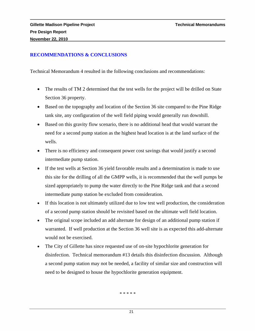
RECOMMENDATIONS & CONCLUSIONS
Technical Memorandum 4 resulted in the following conclusions and recommendations:
• The results of TM 2 determined that the test wells for the project will be drilled on State
Section 36 property.
• Based on the topography and location of the Section 36 site compared to the Pine Ridge
tank site, any configuration of the well field piping would generally run downhill.
• Based on this gravity flow scenario, there is no additional head that would warrant the
need for a second pump station as the highest head location is at the land surface of the
wells.
• There is no efficiency and consequent power cost savings that would justify a second
intermediate pump station.
• If the test wells at Section 36 yield favorable results and a determination is made to use
this site for the drilling of all the GMPP wells, it is recommended that the well pumps be
sized appropriately to pump the water directly to the Pine Ridge tank and that a second
intermediate pump station be excluded from consideration.
• If this location is not ultimately utilized due to low test well production, the consideration
of a second pump station should be revisited based on the ultimate well field location.
• The original scope included an add alternate for design of an additional pump station if
warranted. If well production at the Section 36 well site is as expected this add-alternate
would not be exercised.
• The City of Gillette has since requested use of on-site hypochlorite generation for
disinfection. Technical memorandum #13 details this disinfection discussion. Although
a second pump station may not be needed, a facility of similar size and construction will
need to be designed to house the hypochlorite generation equipment.
* * * * *

Gillette Madison Pipeline Project Technical Memorandums Pre Design Report November 22, 2010
22
3.5 TM 5 – WATER QUALITY AND BLENDING STRATEGIES
DESCRIPTION
When any municipality is considering an additional water source for their system, it is important
to evaluate the quality of the additional source itself as well as how it will be integrated into the
overall distribution strategy. As discussed in previous Technical Memorandums, the additional
source of water for the COG under the GMPP will be obtained from the Madison formation with
incorporation of another Madison well field. Since the Madison formation source is already
being utilized by the COG, there is not as much concern with the quality of the additional water
source as there is concern about where it is delivered within the City’s distribution system.
Under the City’s current operating strategy, the existing Madison well field water is blended with
Fort Union & Fox Hills (when used) water from Pump Station #1 and this blended source is then
delivered to Reservoir Z1-R3 (Dump Hills). The water is also transported to Reservoir Z1R4
which also feeds the distribution system.
Schematic of Existing System
Under the current scenario, the entire City receives the same blended source of water and
therefore similar quality as shown above. The main concern that the COG staff has raised

Gillette Madison Pipeline Project Technical Memorandums Pre Design Report November 22, 2010
23
regarding the additional source under the GMPP, is the potential to have different water qualities
in various sections of their distribution system due to different blending scenarios. For instance,
as shown below, the original concept that was being considered would route the Madison water
from the new well field directly to Reservoir Z1-R4. As such this water would not be blended
with any other sources resulting in varying water qualities for residents and businesses
depending on whether they are served from Reservoir Z1-R3 or Z1-R4.
Schematic of Proposed System without Blending
The objectives of Technical Memorandum 5 are as follows:
• Present the existing groundwater sources and their production capacity.
• Evaluate historic water quality from each ground water source.
• Review water quality standards and COG water quality goals.
• Review projected system water demands from 2010 to 2040 to illustrate when increased
reliance on the Madison source is necessary to supplement the fixed capacity of the
existing COG wells.
• Evaluate potential future blending scenarios, the resulting water quality, and the affect
(difference) on distribution system water quality.
Each of these objectives is summarized in the following tables:

Gillette Madison Pipeline Project Technical Memorandums Pre Design Report November 22, 2010
24
Existing Groundwater Sources
Groundwater Source Average Day Peak Day
Capacity (gpm)
Capacity (MGD)
Capacity (gpm)
Capacity(MGD)
Fort Union1,2 930 1.34 1,906 2.74
Fox Hills/Lance3 0 0 0 0
Madison4 6,565 9.45 6,565 9.45
Total 7,495 10.79 8,471 12.19 Notes: 1. Fort Union average capacity is limited by annual State Engineers Office cap, not system capacity. 2. Fort Union peak capacity is limited by firm capacity of the well system. 3. The Fox Hills/Lance source will not be used as a primary groundwater source. 4. Madison capacity is limited by the firm capacity of the well field
Existing Groundwater Source Water Quality
Well Identification Total
Capacity(gpm)
Fluoride(mg/L)
TDS (mg/L)
Hardness (mg/L as CaCO3)
Sulfate (mg/L)
Fort Union 2,306 2.03 471 24 0 Existing Fox Hill/Lance 1,650 7.64 1,192 0 24 New/Existing Madison 23,987 0.97 632 486 278
Notes: 1. Capacity for wells S-9, S-17, S-18, S-19, and S-27 are estimated future capacities after “re-drilling”
activities. For the purposes of this analysis, the water quality of these wells is assumed to be the same. 2. Data Source: December 2004 City of Gillette Water Master Plan Report 3. Data Source: August 2007 City of Gillette Long Term Water Supply Level II Study
Water Quality Standards or Goals
Parameter Primary
Standard (mg/L)
Secondary Standard
(mg/L)
Water Quality Goal
(mg/L)
Fluoride 4.0 2.0 2.0 Hardness -- -- 500
TDS -- 500 500 Sulfate -- 250 250
Iron -- 0.3 0.3 Sodium -- 250 250
Gillette Madison Pipeline Project Technical Memorandums Pre Design Report November 22, 2010
25
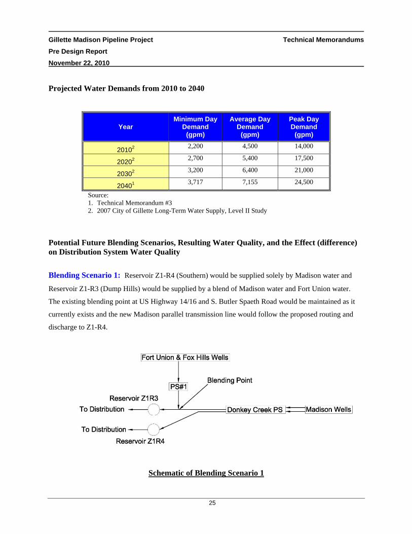
Projected Water Demands from 2010 to 2040
Year Minimum Day
Demand (gpm)
Average Day Demand
(gpm)
Peak Day Demand
(gpm)
20102 2,200 4,500 14,000
20202 2,700 5,400 17,500
20302 3,200 6,400 21,000
20401 3,717 7,155 24,500
Source: 1. Technical Memorandum #3 2. 2007 City of Gillette Long-Term Water Supply, Level II Study
Potential Future Blending Scenarios, Resulting Water Quality, and the Effect (difference) on Distribution System Water Quality
Blending Scenario 1: Reservoir Z1-R4 (Southern) would be supplied solely by Madison water and
Reservoir Z1-R3 (Dump Hills) would be supplied by a blend of Madison water and Fort Union water.
The existing blending point at US Highway 14/16 and S. Butler Spaeth Road would be maintained as it
currently exists and the new Madison parallel transmission line would follow the proposed routing and
discharge to Z1-R4.
Schematic of Blending Scenario 1

Gillette Madison Pipeline Project Technical Memorandums Pre Design Report November 22, 2010
26
Blending Scenario 1 Resulting Water Qualities:
Reservoir Z1-R4
Year Fluoride
mg/L
Hardness
mg/L as
CaCO3
TDS
mg/L
Sulfate
mg/L
All Demands
2010 0.97 486 632 278
2020 0.97 486 632 278
2030 0.97 486 632 278
2040 0.97 486 632 278
Reservoir Z1-R3
Year
Total
Demand
Madison
Supply
Fort
Union
Supply
30-inch
Line
Demand
42-inch
Line
Demand
Fluoride Hardness TDS Sulfate
gpm gpm gpm gpm gpm mg/L mg/L as
CaCO3
mg/
L mg/L
Minimum Demand
2010 2,200 1,500 700 525 975 1.58 222 540 119 2020 2,700 2,000 700 700 1,300 1.50 255 551 139 2030 3,200 2,500 700 875 1,625 1.44 280 560 154 2040 3,717 3,017 700 1,056 1,961 1.39 302 568 167
Average Demand
2010 4,500 3,570 930 1,250 2,321 1.42 289 563 159 2020 5,400 4,470 930 1,565 2,906 1.37 313 572 174 2030 6,400 5,470 930 1,915 3,556 1.32 335 579 187 2040 7,155 6,225 930 2,179 4,046 1.29 348 584 195
Peak Demand
2010 14,000 12,094 1,906 4,233 7,861 1.30 342 582 191 2020 17,500 15,594 1,906 5,458 10,136 1.25 366 590 206 2030 21,000 19,094 1,906 6,683 12,411 1.21 383 596 216 2040 24,500 22,594 1,906 7,908 14,686 1.18 396 600 224

Gillette Madison Pipeline Project Technical Memorandums Pre Design Report November 22, 2010
27
Blending Scenario 1 Affect (Difference) Water Qualities Reservoir Z1-R3 vs. Z1-R4:
Year
Fluoride Hardness TDS Sulfate
mg/L mg/L as
CaCO3 mg/L mg/L
Minimum Demand
2010 0.60 264 92 158 2020 0.53 231 80 139 2030 0.47 205 71 123 2040 0.42 184 64 111
Average Demand
2010 0.45 197 68 118 2020 0.39 172 60 103 2030 0.34 151 52 91 2040 0.32 138 48 83
Maximum Demand
2010 0.33 144 50 86 2020 0.27 120 42 72 2030 0.23 103 36 62 2040 0.20 90 31 54
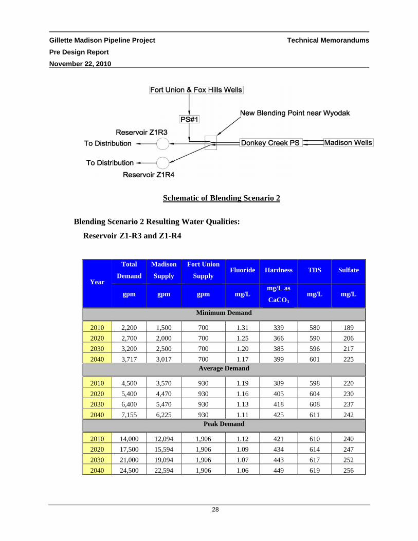
Blending Scenario 2: Transmission modifications would be completed to facilitate the blending
of in-town well water into the new parallel transmission line at a location near the WYODAK
Power Plant. Reservoirs Z1-R3 and Z1-R4 would be supplied by a blend of Madison water and
Fort Union water. The new blending point would be located where the water splits between
Reservoir Z1-R3 and Z1-R4, near WYODAK and Highway 51. This blending alternative would
require an additional 18” PVC pipeline for approximately five miles from the intersection of
Butler Spaeth Road and US Highway 14/16 to WYODAK. There would also be capital and
maintenance costs associated with the blending structure. This cost would be substantial
requiring additional capital funds that are not currently within the identified capital plan.
Gillette Madison Pipeline Project Technical Memorandums Pre Design Report November 22, 2010
28
Schematic of Blending Scenario 2
Blending Scenario 2 Resulting Water Qualities:
Reservoir Z1-R3 and Z1-R4
Year
Total
Demand
Madison
Supply
Fort Union
Supply Fluoride Hardness TDS Sulfate
gpm gpm gpm mg/L mg/L as
CaCO3 mg/L mg/L
Minimum Demand
2010 2,200 1,500 700 1.31 339 580 189 2020 2,700 2,000 700 1.25 366 590 206 2030 3,200 2,500 700 1.20 385 596 217 2040 3,717 3,017 700 1.17 399 601 225
Average Demand
2010 4,500 3,570 930 1.19 389 598 220 2020 5,400 4,470 930 1.16 405 604 230 2030 6,400 5,470 930 1.13 418 608 237 2040 7,155 6,225 930 1.11 425 611 242
Peak Demand
2010 14,000 12,094 1,906 1.12 421 610 240 2020 17,500 15,594 1,906 1.09 434 614 247 2030 21,000 19,094 1,906 1.07 443 617 252 2040 24,500 22,594 1,906 1.06 449 619 256

Gillette Madison Pipeline Project Technical Memorandums Pre Design Report November 22, 2010
29
Blending Scenario 2 Affect (Difference) Water Qualities Reservoir Z1-R3 vs. Z1-R4:
As reflected in the table above, under this scenario the water supplied to both Reservoir
Z1-R3 and Z1-R4 would come from the same blending point and, therefore, there would
not be a difference in the water quality.
RECOMMENDATIONS & CONCLUSIONS
The effect of the GMPP project on the current water quality is a very important factor to be
considered for the designed improvements. Public perception can often play a vital role in these
considerations. If the water quality changes significantly or there is a significant difference in
the quality of water provided to residential and/or commercial users, this could lead to criticism.
The evaluation of the blending strategies and their resulting impact on water quality is therefore
necessary to determine the direction for the design of the GMPP improvements. Technical
Memorandum 5 presented the following conclusions and recommendations:
• Regardless of the blending scenario selected, the primary and secondary water quality
standards are being met except for sulfate which is over the secondary standard for both
scenarios.
• In meetings with the City staff regarding this evaluation, it was determined that the
hardness was the water quality attribute of most importance to the public. The table
below summarizes how hardness will be affected by the different blending scenarios.
• It is important to note that as the water demand increases, the difference in water quality
between reservoirs Z1R3 and Z1R4 will decrease due to a greater reliance on the
Madison aquifer water supply.
• Initially the team felt that the differences in hardness between reservoir Z1R4 and Z1R3
under Scenario 1 would not be significant enough to warrant changing the existing
blending point. The cost weighed against the benefit seemed high since a lot of capital

Gillette Madison Pipeline Project Technical Memorandums Pre Design Report November 22, 2010
30
costs would be incurred to construct additional piping and a new blending facility to
achieve the same hardness throughout the system.
Year Scenario 1 Scenario 2 Difference between Scenario 1 & 2
Z1R4 Z1R3 Z1R4 & Z1R3 Z1R4 Z1R3
Minimum Demand
2010 486 222 339 ‐147 117 2020 486 255 366 ‐120 111 2030 486 280 385 ‐101 104 2040 486 302 399 ‐87 97
Average Demand
2010 486 289 389 ‐97 101 2020 486 313 405 ‐81 92 2030 486 335 418 ‐68 83 2040 486 348 425 ‐61 77
Maximum Demand
2010 486 342 421 ‐65 79 2020 486 366 434 ‐52 68 2030 486 383 443 ‐43 59 2040 486 396 449 ‐37 53
• COG staff stressed during the May 11, 2010 meeting the importance for them to have the
same water quality (especially hardness) delivered throughout their system even if
additional cost were incurred to build the improvements necessary to achieve this goal.
The philosophy is that since the GMPP is such a large, costly project, they do not want to
be put in the position with the general public to have to explain why the improvements
created a scenario with varying water qualities.
• Based on COG staff input, the design of the GMPP will pursue Blending Scenario 2 to
provide consistent water quality. A significant amount of funding for design and
construction of an additional 18” PVC pipeline for approximately five miles and the
capital and maintenance cost of the blending structure will be required. As such,

Gillette Madison Pipeline Project Technical Memorandums Pre Design Report November 22, 2010
31
Blending Scenario 2 will require additional capital funds that are not currently within the
identified capital plan. The scope of this project will also require amendment for the
design of these facilities.
• It should be noted that although the net effect of Blending Scenario 2 will provide
consistent water qualities, based on the above table the net effect on the hardness for
reservoir Z1-R3 will be increased. This effect will decrease over time with increased
demand and more reliance on the Madison formation source.
* * * * *

Gillette Madison Pipeline Project Technical Memorandums Pre Design Report November 22, 2010
32
3.6 TM 6 – DETERMINATION OF STORAGE REQUIREMENTS
DESCRIPTION
Technical Memorandum 2 recommends the addition of thirteen (13) new Madison formation
production wells to the COG system. The addition of these wells must take into consideration
additional transmission main storage requirements. The ten (10) existing Madison wells
currently feed to a 1.1 million gallon (MG) tank and a 0.2 MG tank which sit next to each other
at the Madison Pump Station site. The water from the existing wells is chlorinated prior to
entering these two storage tanks. The tanks then feed the Madison Pump Station which delivers
the water to two storage reservoirs at the Pine Ridge site which have capacities of 0.8 MG and
0.2 MG. From the Pine Ridge storage reservoirs the water flows by gravity to the Donkey Creek
Pump Station where it is once again “boosted” to the City of Gillette. The general setup is
shown schematically in Figure 1.
The findings of TM 2 provide recommendations for the new Madison Well Field (NMWF) to be
located on State Section 36, which is just northwest of the existing Pine Ridge tanks site. The
purpose of this TM is to determine what additional storage will be required with consideration of
this NMWF site and both the hydraulic and disinfection contact time requirements of the project.
The storage volume requirement for the disinfection contact time will be calculated with the
storage volume at the minimum water level in the reservoir. Figure 2 illustrates the storage
requirements in one reservoir. As seen by the diagram, the portion of the storage reservoir above
the minimum water level would satisfy the hydraulic storage requirement and the portion of the
storage volume below the minimum water level would satisfy the disinfection contact time
requirement.

Gillette Madison Pipeline Project Technical Memorandums Pre Design Report November 22, 2010
33
Figure 1 Existing Madison and Pine Ridge Facilities
Figure 2 Diagram of Storage Requirements
Technical Memorandum 13 provides an evaluation of the disinfection alternatives for the GMPP.
The TM discusses that the new Madison Well Field will require either a dedicated disinfection
Gillette Madison Pipeline Project Technical Memorandums Pre Design Report November 22, 2010
34
system or a larger overall disinfection system to provide a chlorine residual for the entire
Madison supply. The conclusions of TM 13 recommend the design and construction of an on-
site sodium hypochlorite facility at the Pine Ridge site to eventually disinfect all of the COG
Madison formation wells. These conclusions were factored into the disinfection portion of the
storage tank sizing considerations.
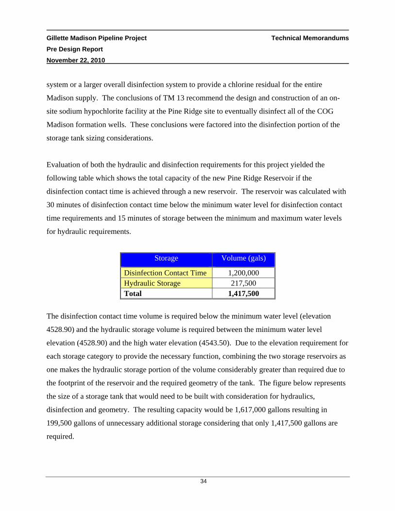
Evaluation of both the hydraulic and disinfection requirements for this project yielded the
following table which shows the total capacity of the new Pine Ridge Reservoir if the
disinfection contact time is achieved through a new reservoir. The reservoir was calculated with
30 minutes of disinfection contact time below the minimum water level for disinfection contact
time requirements and 15 minutes of storage between the minimum and maximum water levels
for hydraulic requirements.
Storage Volume (gals)
Disinfection Contact Time 1,200,000 Hydraulic Storage 217,500 Total 1,417,500
The disinfection contact time volume is required below the minimum water level (elevation
4528.90) and the hydraulic storage volume is required between the minimum water level
elevation (4528.90) and the high water elevation (4543.50). Due to the elevation requirement for
each storage category to provide the necessary function, combining the two storage reservoirs as
one makes the hydraulic storage portion of the volume considerably greater than required due to
the footprint of the reservoir and the required geometry of the tank. The figure below represents
the size of a storage tank that would need to be built with consideration for hydraulics,
disinfection and geometry. The resulting capacity would be 1,617,000 gallons resulting in
199,500 gallons of unnecessary additional storage considering that only 1,417,500 gallons are
required.

Gillette Madison Pipeline Project Technical Memorandums Pre Design Report November 22, 2010
35
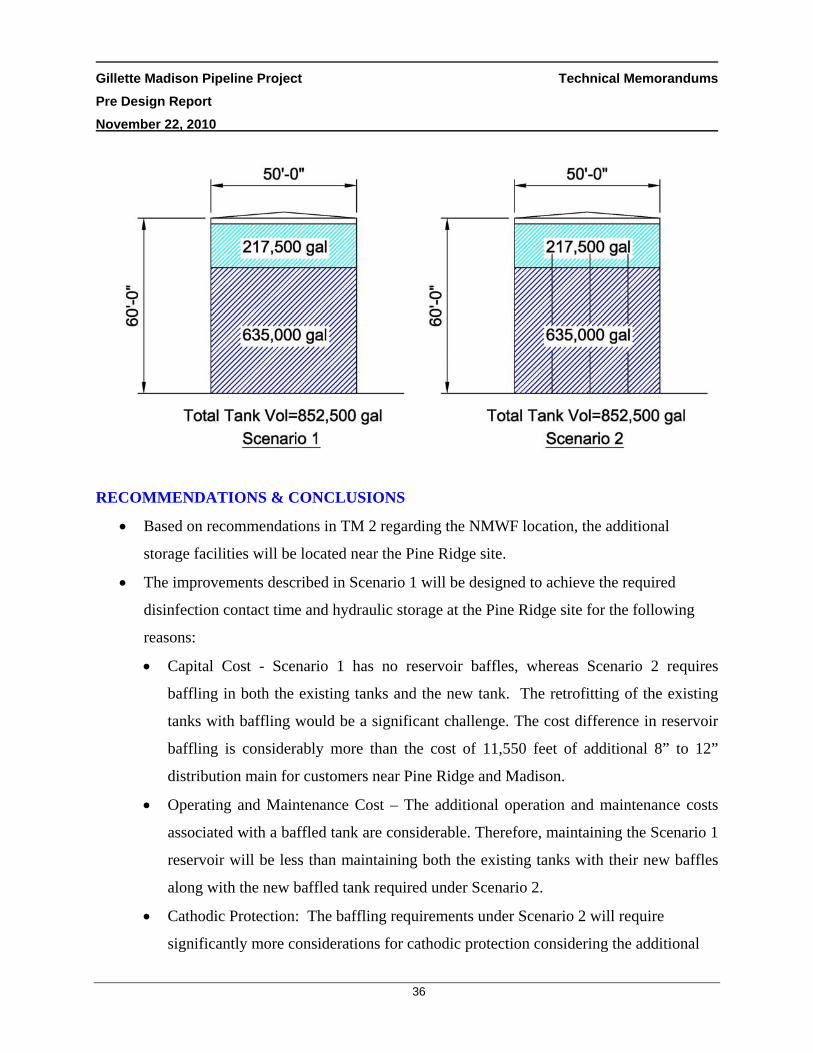
In an effort to reduce the size of the tank and eliminate the unnecessary storage, other potential
scenarios were developed for consideration to achieve both the volume required for disinfection
contact time and hydraulics as follows:
Scenario 1
A. Proposes installation of a new reservoir (~0.85 MG) at the Pine Ridge site for only hydraulic considerations.
B. Utilize the existing 30-inch and new 42-inch discharge lines from the existing and new tanks, for the first 7,600 feet, to allow 30 minutes of contact time in order to achieve the disinfection requirements to the first customers.
C. Connect a new 8-inch or 12-inch distribution main to the 42-inch and/or 30-inch transmission lines at the 7,600 foot location. Extend the distribution piping for approximately 11,550 feet to serve existing services including the service near the existing Madison site.
Scenario 2
A. Install baffling in both the 0.2 MG and 0.8 MG existing reservoirs at Pine Ridge. B. Separate the inlet and outlet of the Pine Ridge reservoirs. C. Install a new reservoir (~0.85 MG) at Pine Ridge that is well-baffled.
Gillette Madison Pipeline Project Technical Memorandums Pre Design Report November 22, 2010
36
RECOMMENDATIONS & CONCLUSIONS
• Based on recommendations in TM 2 regarding the NMWF location, the additional
storage facilities will be located near the Pine Ridge site.
• The improvements described in Scenario 1 will be designed to achieve the required
disinfection contact time and hydraulic storage at the Pine Ridge site for the following
reasons:
• Capital Cost - Scenario 1 has no reservoir baffles, whereas Scenario 2 requires
baffling in both the existing tanks and the new tank. The retrofitting of the existing
tanks with baffling would be a significant challenge. The cost difference in reservoir
baffling is considerably more than the cost of 11,550 feet of additional 8” to 12”
distribution main for customers near Pine Ridge and Madison.
• Operating and Maintenance Cost – The additional operation and maintenance costs
associated with a baffled tank are considerable. Therefore, maintaining the Scenario 1
reservoir will be less than maintaining both the existing tanks with their new baffles
along with the new baffled tank required under Scenario 2.
• Cathodic Protection: The baffling requirements under Scenario 2 will require
significantly more considerations for cathodic protection considering the additional

Gillette Madison Pipeline Project Technical Memorandums Pre Design Report November 22, 2010
37
metallic surfaces. This additional baffling also needs to be monitored and maintained
in the future.
• The schematic of the recommendations under Scenario 1 are shown below:
* * * * *

Gillette Madison Pipeline Project Technical Memorandums Pre Design Report November 22, 2010
38
3.7 TM 7 – HYDRAULIC MODELING
The GMPP requires the addition of many different components involving piping, pumping, and
storage. The interaction and sizing of these components is vital to the overall function of the
GMPP system. As such, a hydraulic evaluation is required to confirm these interactions and
determine the design parameters for these components moving forward into their design. The
purpose of Technical Memorandum 7 is to discuss the hydraulic modeling performed to make
these sizing determinations with regards to both existing and proposed facilities. The TM
provides an overview of how the GMPP model was developed and discussion of the analysis and
results. Issues discussed include the model properties, the model alternatives, and the model
analysis of those alternatives. The water model used for the GMPP modeling originated from the
2009 City of Gillette Water Model updated by Morrison Maierle, Inc. (MMI) in December 2009.
The 2009 MMI model is the product of a number of evolutionary adjustments and updates to the
model, which has been worked on by numerous consultants. Four alternatives were modeled to
evaluate different blending scenarios between the traditionally “soft” water from Pump Station
#1, and the “hard” water from the existing Madison line and the proposed GMPP transmission
main. As presented earlier, Technical Memorandum 5 discusses the blending issues in great
detail.
Modeling Property Derivations:
• Demands
The following table shows the total average day demands (ADD) and peak day demands
(PDD) considered in the modeling for the GMPP projection period.

Gillette Madison Pipeline Project Technical Memorandums Pre Design Report November 22, 2010
39
COG DEMANDS
Year ADD (gpm)
PDD (gpm)
2010 4,981 17,0582020 5,749 19,6882030 6,414 21,9642040 7,155 24,504
Technical Memorandum 9, Plan for Regional Water Supply, presented later evaluates
regionalization issues and potential users along the transmission line to be constructed as
part of the GMPP. The following table identifies the possible interconnects to be
considered and their anticipated demands over the GMPP projection period.
REGIONAL TRANSMISSION MAIN CONNECTIONS
Location 2010 ADD(gpm)
2020 ADD (gpm)
2030 ADD (gpm)
2040 ADD (gpm)
Crestview Line 50.96 56.85 63.42 70.74 Antelope Valley Line 151.99 169.55 189.15 211.01 Central Campbell Cty Line 1 33.31 37.16 41.46 46.25 Nickelson Farms Line 37.18 41.48 46.27 51.62 Meadow Springs Line 72.45 80.82 90.16 100.58 Ward Creek Line 1 60.63 67.64 75.45 84.18 Ward Creek Line 2 2.15 2.39 2.67 2.98
The following table identifies the future in-town demand growth breakdown, which were
placed at three nodes in the model along the new in-town piping alignment.
Location 2010 ADD(gpm)
2020 ADD(gpm)
2030 ADD (gpm)
2040 ADD (gpm)
Future Growth West 72.42 187.92 287.97 399.41 Future Growth Southwest 144.84 375.86 575.94 798.80 Future Growth South 144.84 375.86 575.94 798.80
Gillette Madison Pipeline Project Technical Memorandums Pre Design Report November 22, 2010
40
• Existing Model Changes – in order to simplify the model, all of the old scenarios and
alternatives from prior years were cleared from the model and only the correct model
framework and demands developed as part of this project combined with the calibration
efforts performed in the 2009 modeling effort remained.
• Fire Flow Determinations – were set as follows:
Residential fire flows = 1,500 gpm
Commercial fire flows = 2,500 gpm
Industrial fire flows at 3,500 gpm
A fire flow scenario was set up during peak day demand for each of the four years
modeled
Fire flows were modeled for legislated durations.
• Tank Connections – modeling setup for the following tanks is discussed:
Pine Ridge Tanks
Reservoir Z1-R3 (Dump Hill)
Reservoir Z1-R4 (Sunburst or Southern Tank)
Reservoir Z1-R5 (Hidden Valley)
• Alignment – alignments for new piping are based on 10% designs and alignment for the
existing piping is based on GIS information.
• Pump Curves – new pump design is based on 6 pumps with a firm capacity of 15,300
gpm.
Modeling Alternatives:
• Alternative 1 – Existing Layout (City Existing GIS with 10% Design Proposed)
• Alternative 2 – Reverse Flow Through Existing 30” Madison Line (to satisfy 2040 PDD)
• Alternative 3 – Reverse Flow Through Existing 30” Madison Line (to satisfy 2020 PDD)

Gillette Madison Pipeline Project Technical Memorandums Pre Design Report November 22, 2010
41
• Alternative 4 – New 18” Line to WYODAK (as part of Alternative 1) for blending
purposes to achieve consistent water quality. See TM5.
RECOMMENDATIONS & CONCLUSIONS
• Pipe configurations for both Alternatives 1 and 4 would satisfy demands through the
2040 peak day.
• Pipe configurations under alternatives 2 and 3 require upsizing of the in-town beyond the
WYDOT-imposed size restriction of 36-inch and as such are not considered feasible.
• Alternative 1 provides the most cost effective means of delivering water quantity to the
service area, but it does not deliver consistent water quality across the system.
• Alternative 4 provides consistent blended water quality across the system, but requires an
additional 26,250 linear feet of 18” pipe at cost that could run $5.25 to $7.1 Million.
• In all prior meetings the COG has stressed the desire to have consistent water quality
throughout their system. They do not want to expend the capital on all of the
improvements being constructed under the GMPP only to end up with the potential for
complaints associated with inconsistent water in various parts of Town.
• Alternative 4 is therefore the recommended piping configuration based on the following:
The hydraulic needs of the system up to and including the 2040 peak day are met.
Consistent water quality across the system can be achieved.
The 36-inch pipeline restriction set by WYDOT is met.
* * * * *

Gillette Madison Pipeline Project Technical Memorandums Pre Design Report November 22, 2010
42
3.8 TM 8 – 10% TRANMISSION PIPELINE ALIGNMENT AND HYDRAULIC ANALYSIS
DESCRIPTION
The proposed Madison well field site is remote from the City of Gillette distribution system and
will require almost 44 miles of transmission piping to bring the water from this source to the
COG. The existing Madison pipeline currently delivers flows to the distribution system via a 30-
inches diameter transmission line from the existing Madison well field. As such, corridors
utilized for the existing 30-inch transmission line should be the first considered for the new
waterline. The purpose of TM 8 is to provide a preliminary overview of the alignment to be
considered for the 10% design submittal, discuss potential diameters requirements for the line
with consideration of a 21 MGD flow capacity and to provide preliminary information for
easements that might be required for the construction of the preferred alignment.
The general alignment for the proposed transmission pipeline is shown in Exhibit A of TM 8
which can be found in the appendix. The COG has directed the consultant team to pursue the
alternative alignment shown on Drawing A1 and A2 for the sections of the transmission line
between Southern Drive and Highway 59. The overall alignment from the COG distribution
system to the Madison well field site can generally be described as follows:
• Begins at the Z1-R4 tank located on Southern Drive
• East along Southern Drive to Swanson Road
• South along Swanson Road to the Elsner property
• East through the Elsner property to Schoonover Drive
• East on Schoonover Drive to Patty Avenue
• North on Patty Avenue to the NBI Development property
• East through the NBI Development and Department of Interior property to Highway 59
• South along Highway 59 to Union Chapel Road
• East along Union Chapel Road to the Pickrel Land & Cattle Co, Inc property

Gillette Madison Pipeline Project Technical Memorandums Pre Design Report November 22, 2010
43
• North and north east through the Pickerel Land & Cattle Co, Inc. property and the
WYODAK Resources Development Corp. property to Highway 51 near the WYODAK
Mine
• East along Highway 51 to the Donkey Creek Pump Station
• East from the Donkey Creek Pump Station along Highway 51 through the Town of Rozet
• East along Highway 51 to County Road D
• North along County Road D to the Robinson Family Limited Partnership (RFLP)
property
• Northeast through the RFLP property, Bureau of Reclamation property, and Schuricht
Land and Real Estate Limited Partnership property to US Highway 14
• North and east along US Highway 14 to the Pine Ridge tank site
The majority of the alignment will be within or adjacent to Wyoming Department of
Transportation (WYDOT) right-of-way including the following areas:
ALIGNMENT SECTIONS WITHIN WYDOT ROW
State Highway 59 from Southern Drive to Union Chapel Road
State Highway 51 from WYODAK to D Road
US Highway 14 from the Schuricht property to the Pine Ridge tank site
WYDOT has indicated that they will allow the waterline to be placed within their right-of-way
with the proper license agreements and review of the design drawings. The City of Gillette may
also need to obtain “blanket easements” or “utility easements” from the adjacent landowners
should WYDOT only hold easements for portions of the property over roadway areas.
The TM identifies criteria that were used to develop the layout for the new transmission line,
which will be given consideration throughout the project. These include the following:

Gillette Madison Pipeline Project Technical Memorandums Pre Design Report November 22, 2010
44
LAYOUT CRITERIA
Utilize existing ROW and easements Avoid open cut construction in Campbell
County
Mirror existing Madison Transmission line
when possible
Optimize access to the transmission line with
consideration for maintenance
Minimize disturbance to affected areas
Minimize railroad crossings and avoid
longitudinal encroachments
Avoid environmentally sensitive areas
Limit to a 60 foot wide permanent and 40
foot wide temporary easement where
possible
Minimize road crossings
Provide a 100 foot separation from high
voltage power where possible
The TM provides the following summary tables:
• Table 1 – 10% Transmission Pipeline Alignment. Provides a general narrative for
each drawing including the pipeline area, existing Madison Transmission line location,
new alignment considerations, and proposed alignment location.
• Table 2 – 10% Transmission Pipeline Easements. Provides preliminary information
for each drawing regarding the property owners from whom permanent easements,
blanket easements, license agreements, and crossing agreements may be required. This is
based strictly on the best available assessor’s information.
The TM also discusses the materials that might be allowed for the transmission piping
understanding that Technical Memorandum 10 “Pipeline Material Evaluations and
Recommendations” will be dedicated to this topic.
Gillette Madison Pipeline Project Technical Memorandums Pre Design Report November 22, 2010
45
Finally, a hydraulic grade line exercise is presented to provide very preliminary estimates of
possible pipeline diameters and pressure classes for a number of different pipeline material
combinations. The results of the hydraulic modeling in TM 7 will be used to determine the size
(diameter) as well as the thickness and pressure class requirements of the piping for the project.
RECOMMENDATIONS & CONCLUSIONS
• The general alignment described above will be utilized to prepare the 10% Water
Transmission Line design for the GMPP. The Technical Memorandum evaluates some
minor alternatives along certain areas of the alignment. The complete TM can be found
in the Appendix along with the drawings of the main alignment and alternatives.
* * * * *

Gillette Madison Pipeline Project Technical Memorandums Pre Design Report November 22, 2010
46
3.9 TM 9 – PLAN FOR REGIONAL WATER SUPPLY
DESCRIPTION
The water transmission pipeline to be constructed under the Gillette Madison Pipeline Project
GMPP will cover almost 44 miles and will pass by several communities between the City of
Gillette and the Madison well field. Construction of a pipeline of this length and size presents
opportunities for consideration of how a system like this might fit into the current and future
plans of these regional communities. The following recent studies have been performed for the
COG:
• 2007 City of Gillette Long Term Water Supply Level II Study, (Level II) • Gillette Regional Master Plan Level I Study, August 2009 (GRMP) • Regional System Participant Connections Study, May 2010 (RSPCS)
The GRMP and RSPCS both evaluated this regional concept at different levels with varying
results. The COG requested a review of these documents and interpretation of how the
information from each should come together to formulate the design parameters for the GMPP
components. The purpose of Technical Memorandum 9 is to summarize the regional water
supply plan considerations that will have an impact on design of the GMPP. The scope of the
GMPP relative to the regional water supply includes:
• Consideration of the 2040 water demands for potential regional system participants within the possible regional water system service area
• Inclusion of regional connection stubs with valves for potential regional participants along the proposed Madison transmission pipeline
The TM briefly describes the approaches for each of the above studies. The City requested that
the design of this project consider all potential regional participants listed in the RSPCS, which
includes regional participants within both the possible and probable service areas. The RSPCS
projected peak day demands and recommended regional connection locations are evaluated in
this TM for use in the regional water supply plan for the GMPP.

Gillette Madison Pipeline Project Technical Memorandums Pre Design Report November 22, 2010
47
The TM covers the following areas in making determinations regarding which participants
(communities) should be considered, what demands should be factored into the capacity
considerations for the GMPP and where these participants might connect.
• Potential Regional Participants and Proposed Connection Lines
• Regional Water Demands and Class of Service
• Regional Water Storage Considerations
• Regional Water Quality Considerations
• Regional Service Connection Implementation and Phasing
RECOMMENDATIONS & CONCLUSIONS
• Comparisons of the regional demand projections in the Level II study, RSPCS and
Technical Memorandum 3 differed by less than 3%.
• The regional demand projection from the Level II study is 5,114 gpm
• The regional demand projection from the RSPCS is 4,806 gpm.
• The more conservative Level II future regional demand projection of 5,114 gpm will be
used for the design of the pipeline.
• The connection locations proposed in the RSPCS appear to be compatible with the
transmission waterline alignments presented in TM 8 and will be used for the preliminary
layout of the connection stubs with the exception of the Antelope Valley and Crestview
connections.
• The connection stubs for Antelope Valley and Crestview will be designed along the
revised alignment (see TM8) at or near the intersection of Schoonover Street and Patty
Avenue.
• Currently, the scope of this project includes connection stubs for the Class B participants,
(Class B – Shared water service with water sold from the participant’s water supply to the
regional system, with the capability for providing full water service without fire
Gillette Madison Pipeline Project Technical Memorandums Pre Design Report November 22, 2010
48
protection from the regional system). However, it does not consider connection of the
class B participants to contribute excess water supply to the system. Similarly, the scope
of this project includes connection stubs only to the potential regional participants located
along the proposed pipeline alignment. Stub-outs for potential regional participants not
located along the pipeline alignment are not included in the GMPP and are anticipated to
be addressed in separate regional projects.
* * * * *

Gillette Madison Pipeline Project Technical Memorandums Pre Design Report November 22, 2010
49
3.10 TM 10 – PIPELINE MATERIAL EVALUATION AND RECOMMENDATIONS
DESCRIPTION
For a project consisting of almost 44 miles of large transmission line construction, materials
selection is a key component to its success. There are many variables that will affect what
materials should be specified for any pipeline project including:
• Material conveyed
• Pipe diameter availability
• External pressures due to depths, traffic, or other items that increase dead load
• Internal Pressures (including test pressure)
• Corrosion resistance and compatibility with existing soils and groundwater conditions
• Expected pipeline life span.
The existing Madison water transmission line has had some severe maintenance issues over the
years. A separate project was conducted by the COG, under separate contract, to evaluate these
issues, titled the Gillette Madison Pipeline Internal Pilot Study. The study evaluated the cathodic
protection of the existing line and issues related to the very corrosive soils in this region in an
effort to determine and correct the deficiencies. These concerns and review of existing soils
information placed corrosion considerations as a major factor in the selection of materials for this
project. As such, the scope of work for the GMPP requires an evaluation of different pipeline
material and recommendations for materials that will be allowed to bid on the project. Based on
the corrosion concerns on the existing lines, a part of this evaluation is to include cathodic
protection considerations and requirements. The purpose of this technical memorandum is to
provide the procedure and framework to be utilized to make determinations on how to proceed
with cathodic evaluations and subsequently what materials will be allowed in the bids for the
GMPP.

Gillette Madison Pipeline Project Technical Memorandums Pre Design Report November 22, 2010
50
Cathodic Protection
Understanding the importance that cathodic protection will have in the success of this project,
the services of experts with cathodic protection design will be necessary to assure that the
existing conditions are properly assessed and that each pipe material allowed is specified to
provide a full service life under these conditions. As such a Cathodic Protection workshop was
held on June 10, 2010 with two reputable cathodic protection design firms. Members of the
COG and WWDC staffs participated in this workshop. The purpose of the workshop was to
accomplish the following:
• Provide a comprehensive discussion from 2 different perspectives of the technical and
economical issues associated with cathodic protection in general.
• Gain a better understanding of the cathodic protection system designs that are available
for the GMPP and what will best suit the project based on cost, pipe protection and
operation.
• Determine which firm would best serve the COG for the cathodic protection designs for
the GMPP.
The firms presenting, their representatives and the topics covered are as follows:
• Rust Not – Mr. Bill Spickelmire
• AC&C teamed with Corrpro – Mr. Charles Waits
CATHODIC WORKSHOP DISCUSSION TOPICS
Cathodic Protection Methodology for Each Pipe Material Soil Conditions Noted in Old Geotechnical Reports Provided to Each Firm for Review
Joint Bonding Requirements High Voltage Line Considerations
Construction Inspection and Testing Lessons Learned from Existing Madison Pipeline Failures
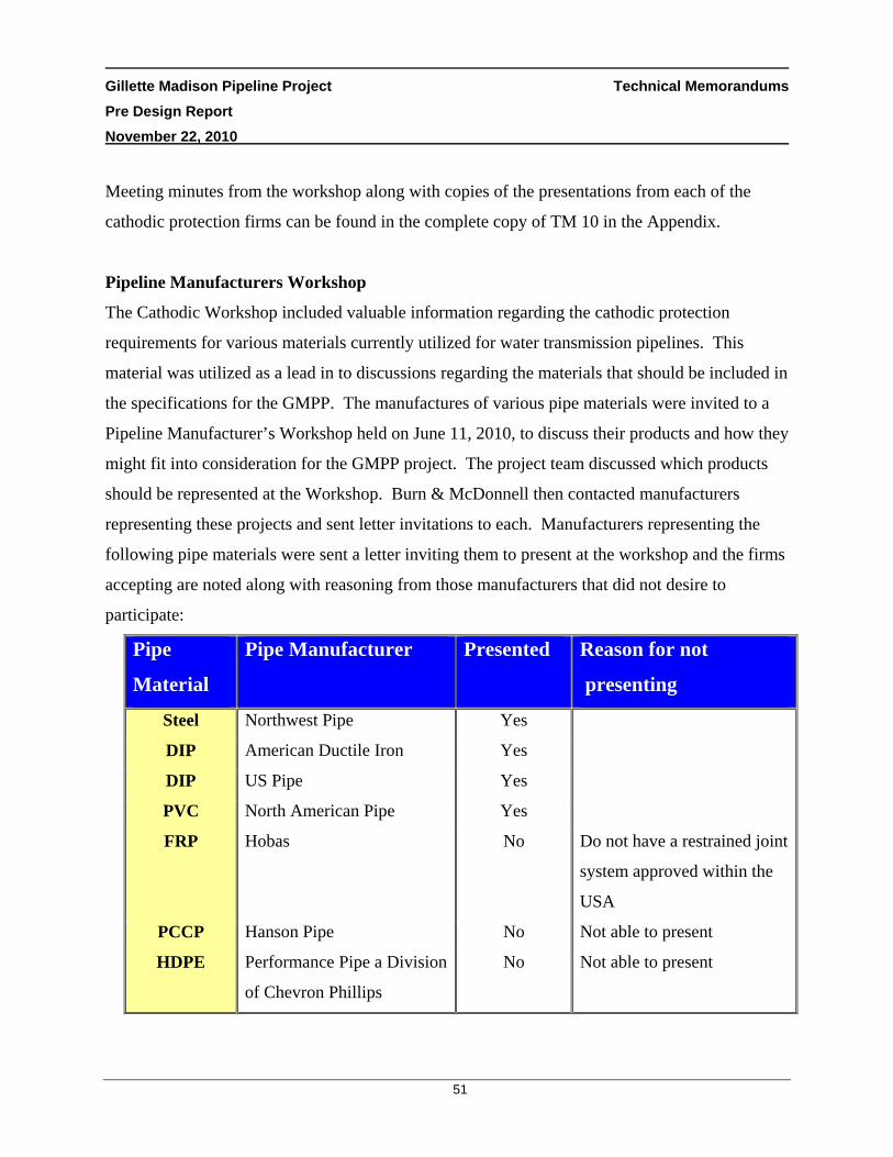
Gillette Madison Pipeline Project Technical Memorandums Pre Design Report November 22, 2010
51
Meeting minutes from the workshop along with copies of the presentations from each of the
cathodic protection firms can be found in the complete copy of TM 10 in the Appendix.
Pipeline Manufacturers Workshop
The Cathodic Workshop included valuable information regarding the cathodic protection
requirements for various materials currently utilized for water transmission pipelines. This
material was utilized as a lead in to discussions regarding the materials that should be included in
the specifications for the GMPP. The manufactures of various pipe materials were invited to a
Pipeline Manufacturer’s Workshop held on June 11, 2010, to discuss their products and how they
might fit into consideration for the GMPP project. The project team discussed which products
should be represented at the Workshop. Burn & McDonnell then contacted manufacturers
representing these projects and sent letter invitations to each. Manufacturers representing the
following pipe materials were sent a letter inviting them to present at the workshop and the firms
accepting are noted along with reasoning from those manufacturers that did not desire to
participate:
Pipe
Material
Pipe Manufacturer Presented Reason for not
presenting
Steel Northwest Pipe Yes
DIP American Ductile Iron Yes
DIP US Pipe Yes
PVC North American Pipe Yes
FRP Hobas No Do not have a restrained joint
system approved within the
USA
PCCP Hanson Pipe No Not able to present
HDPE Performance Pipe a Division
of Chevron Phillips
No Not able to present

Gillette Madison Pipeline Project Technical Memorandums Pre Design Report November 22, 2010
52
Each manufacturer was allowed 45 minutes to discuss their product followed by a question and
answer period. They were requested to cover the following topics at a minimum:
PIPE MANUFACTURER WORKSHOP DISCUSSION TOPICS
Product History
Expected Service Life
Pipe Jointing Requirements
Restrain Joint Types
Cathodic Protection Requirements
Fittings
Pressure Class or Thickness Class Design
Linings/Coatings
Installation Procedure
Service Connection Type and Requirements
Production and Delivery Lead Times/Concerns
Advantages of Product for Use on the GMPP
Disadvantages of the Product for Use on the GMPP
Nearest Manufacturing Facility and Transport Requirements
Meeting minutes from the workshop along with the presentations from each of the pipeline
manufacturer can be found in the full copy of TM 10 which is included in the Appendix.
RECOMMENDATIONS & CONCLUSIONS
• The recommendations from the workshops are that the following pipe material should be
allowed into the specifications for the project.
Steel – Transmission and In-Town Piping
Ductile Iron – Transmission and In-Town Piping
PVC – Only as pressures allow, with DIP boded coated fittings

Gillette Madison Pipeline Project Technical Memorandums Pre Design Report November 22, 2010
53
• Rust- Not, under the management of Mr. Bill Spickelmire, will be retained to perform the
cathodic protection design for the GMPP. Bill is the most familiar with the system as he
is performing the design of the modifications to the existing Madison water transmission
line cathodic protection system. Since consideration of the cathodic design on the
existing line is an important consideration for the GMPP there are synergistic
opportunities available with utilizing Rust-Not that will benefit the GMPP.
* * * * *
Gillette Madison Pipeline Project Technical Memorandums Pre Design Report November 22, 2010
54
3.11 TM 11 – DRAFT CONSTRUCTION SCHEDULE AND PHASING (WITH CONSIDERATION FOR POTENTIAL FUNDING)
DESCRIPTION
The scope of work for the GMPP requires that a draft construction schedule including any
proposals to phase project construction be developed. As part of this process, we were to obtain
input from the COG and WWDC before including the phasing concepts in the Pre-Design
Report. The purpose of this Technical Memorandum (TM) is to provide the framework of the
phasing and scheduling of the project to date as they correlate to potential funding availability.
The funding time frame is the critical factor in this evaluation because the improvements can
only be constructed as the funding becomes available. Since the funding for the project is
subject to decisions made by the legislature in any given year it is agreed that the scheduling and
phasing will need to be revisited each time the funding scenarios unfold.
The draft of TM 11 was prepared and submitted to the COG and WWDC and discussed during
our May 11, 2010, meetings in Gillette. It will be important to make any determinations
regarding phasing of the project up front, because once design documents are complete it is
inefficient costly to break out only sections of each package for bid. In conversations with the
COG, they shared this view point as well. The TM begins with a brief discussion of the current
plan for packaging the projects; ties this project packaging into the phased funding estimate
presented in the 2007 “Gillette Long-Term Water Supply Phasing Plan” , examines alternative
phasing approaches and makes recommendations with consideration for current funding
predictions. The proposal submitted to the COG for the GMPP assumes that the various
components of the project will be phased as follows:

Gillette Madison Pipeline Project Technical Memorandums Pre Design Report November 22, 2010
55
BASIS OF AWARD PROJECT PACKAGING PACKAGE NUMBER PROJECT COMPONENT
P1 Wells
P2 Well Field Piping
P3 In-Town
P4 Water Transmission Piping
P5 Pump Station
P6
P 7 (Pending)
Storage Reservoir
On-Site Sodium Hypochlorite Generation
The TM, which can be found in the Appendix, presents the “ESTIMATE OF GILLETTE
MADISON PIPELINE PROJECT COSTS – PHASED FUNDING PLAN 6” Table. The Table
is broken into the following phases with assigned funding:
• Phase I: Spring 2011 (Design, Administration, Test Wells and Easement/Permit
Acquisition)
• Phase II: 2011-2012 (Construction)
• Phase III: 2013-2014 (Construction)
• Phase IV: 2015-2016 (Construction)
Packages P1 through P6 are assigned to the Phases where we currently felt they would fit in best
with the City’s overall plans and need for the facilities. Based on these assignments a couple
Phasing/Packaging approaches are discussed in the TM with the following table representing the
recommended approach.

Gillette Madison Pipeline Project Technical Memorandums Pre Design Report November 22, 2010
56
BID YEAR DESIGN PACKAGE Spring 2011 • P1 - Wells
• P2 - Well Field Piping
• P3 - In-Town Piping
End 2012 • P4a -Transmission Piping Segments 3 (Donkey Creek PS to
WYODAK) & 4 (WYODAK to Southern Tank)
• P5 - Donkey Creek Pump Station and Hypochlorite Facility
• P6 – Pine Ridge Storage Facility (Tank or Clearwell)
End 2014 • P4b – Transmission Piping Segments 1 (Madison to
Moorcroft) & 2 (Moorcroft to Donkey Creek PS)
RECOMMENDATIONS & CONCLUSIONS
The construction schedule and phasing was presented in the TM to provide a beginning point for
discussions on how the packages might be built. In their review comments and during the meeting, the
City expressed their current prioritization desires as follows:
PRIORITY CLASSIFICATION PORTION OF WORK TO COMPLETE FIRST • Complete Madison Wells
• Well Field Piping and Appurtenances • SW Gillette Treated Transmission Loop
SECOND • New Electric Substation and Distribution at Pine Ridge
• Hypochlorite Facility at Pine Ridge • Storage at Pine Ridge • Segment 4 Transmission Piping
THIRD • Electric Transmission to Donkey Creek PS • New Substation at Donkey Creek PS • Segment 1, 2, 3 Transmission Piping • Donkey Creek Pump Station
LOWEST RANKING • In-Town Storage Tanks • Regional Extensions (separate)
Gillette Madison Pipeline Project Technical Memorandums Pre Design Report November 22, 2010
57
Following are some of the other items discussed during the May 11 meetings:
• The City indicated that there is no guarantee on funding timing, however, Phase 1 and 2
are funded. It was agreed that the TM would be dynamic and change as knowledge of
funding unfolds with each legislative session.
• The electrical distribution needs are immediate. In-town piping and the transmission
loop to WYODAK would allow the City to connect into the existing 30” Madison line
right away.
• The $226 Million is still the overall target funding.
• The current $40 million funding is for non-construction activities, test wells, and in-town
piping.
• The City would like to combine as much transmission piping as possible from Madison
to WYODAK as funding allows understanding that the Sections from WYODAK to the
Southern Drive tank would be another contract.
• There is currently no funding for electric distribution and no routing has been started by
the City.
* * * * *

Gillette Madison Pipeline Project Technical Memorandums Pre Design Report November 22, 2010
58
3.12 TM 12 – WATER SYSTEM CONDTION/OPERATIONAL REVIEW
DESCRIPTION
The preliminary phase scope of work for the Gillette Madison Pipeline Project (GMPP) includes
a Water System Plan. Part of that plan is the COG requirement for the design team to meet with
their operations staff to discuss condition and operational requirements for the water system.
The first step in this progress began during the December 17, 2009, Meeting 3 (Progress Meeting
1) held at the City of Gillette offices. During that meeting our team visited with several
members of the City’s operations staff to discuss current issues and desires for the future
systems.
This Technical Memorandum starts off with a Discussions to Date section which describes most
of the items that have been shared to date. A meeting was held at the City of Gillette’s offices on
May 12, 2010 with the COG operational staff to further discuss the preferences to be used as the
basis for design of major components of this project including the Pump Station(s), Storage
Reservoir(s), and Water Transmission Pipeline facilities. During this meeting we went through
our Pre-Design Checklist & Questionnaires which outlines items for the City staff to comment
on during the meeting. During the meeting we reviewed these lists and added to them as the
conversations dictated. The TM was used as the basic outline for the meeting agenda and the
minutes for that meeting were distributed to the entire team including the COG and WWDC. As
such the meeting minutes serve as the finalization of this TM and are included in the Appendix.
RECOMMENDATIONS & CONCLUSIONS
Please see the Final TM 12 in the Appendix, for design decisions made for various components
of the GMPP. The TM includes the meeting minutes from our May 12, 2010 meeting.
* * * * *

Gillette Madison Pipeline Project Technical Memorandums Pre Design Report November 22, 2010
59
3.13 TM 13 – EVALUATION OF DISINFECTION ALTERNATIVES
DESCRIPTION
The City of Gillette previously held internal discussions regarding alternative disinfection
methods including gaseous chlorine, bulk sodium hypochlorite delivery, and on-site sodium
hypochlorite generation disinfection. Based on these discussions, the City determined that on-
site sodium hypochlorite generation was strongly preferred for this project primarily due to
safety considerations. In response, Burns and McDonnell prepared Technical Memorandum 13
which develops design criteria and alternatives for the implementation of an on-site sodium
hypochlorite facility to chlorinate the water associated with the GMPP.
The system will be designed with the design criteria summarized below for the ultimate build out
of the system.
DESIGN CRITERIA
Generator Size
Two (2) or more systems
Peak Day Flow = 40.2 MGD
Maximum Dosage = 5 mg/L
Brine Storage Two (2) FRP Tanks
30 Days
Sodium Hypochlorite Storage
Two (2) FRP Tanks
2 Days
Capable of storing 12.5% bulk
delivery
Chemical Metering Pumps
0.5 mg/L at 0.13 MGD
5 mg/L at 40.2 MGD
No turndown <20% of feed range.

Gillette Madison Pipeline Project Technical Memorandums Pre Design Report November 22, 2010
60
One major design consideration is the material usage and waste from the system. The systems
require approximately 3 lbs of salt, 2 kW-hrs of electricity, and 15 gallons of water for each
pound of chlorine produced. The most significant waste resulting from sodium hypochlorite
generation systems is produced during the water softener regeneration cycle. The general
relationship of waste produced per pound of sodium hypochlorite generated will be
approximately 0.7-1.0 gallons of waste water per pound of sodium hypochlorite created.
Therefore, at 40.2 MGD, the softener will discharge approximately 1,500 gallons per day of
waste water. The regeneration solution water quality will be approximately 5,000 mg/L of
calcium, 3,000 mg/L of magnesium, 200 mg/L of sodium, and the salt required to regenerate the
softener.
Disposing of this waste at remote locations may prove problematic. One potential solution is to
inject the softener regeneration water back into the transmission pipeline downstream of the
sodium hypochlorite injection point. Karen Farley of the WDEQ indicated they would consider
allowing injection of the softener recharge back into the pipeline. The volume of this waste is
approximately 0.004% of the total flow and would not affect the overall quality of the water.
Five sites and chemical dosage locations were evaluated as follows:
ON-SITE SODIUM HYPOCHLORITE GENERATION ALTERNATIVES
ALTERNATIVE 1 • One generation facility at Madison for disinfection of the
existing Madison wells.
• One generation facility at the new well field for disinfection of
the new Madison wells.
ALTERNATIVE 2 • One generation facility at the new well field for disinfection of
the new Madison wells
• Long sodium hypochlorite dosage line to the existing Madison
Complex.

Gillette Madison Pipeline Project Technical Memorandums Pre Design Report November 22, 2010
61
ON-SITE SODIUM HYPOCHLORITE GENERATION ALTERNATIVES
(continued)
ALTERNATIVE 3 • One generation facility at the Madison Complex for
disinfection of the existing Madison wells
• Long sodium hypochlorite dosage line to the new Madison
wells.
ALTERNATIVE 4 • One generation facility at the Pine Ridge site.
• The existing Madison wells and new Madison wells would
combine at the Pine Ridge site where sodium hypochlorite
would be dosed.
ALTERNATIVE 5 • One generation facility near the new well fields.
• The existing Madison wells would be pumped to the new
Madison well field and both water supplies would be
chlorinated in a new reservoir near the new Madison wells.
RECOMMENDATIONS & CONCLUSIONS
• Our team recommends Alternative 4 for the implementation of the on-site sodium
hypochlorite facility due to the following advantages:
Only one sodium hypochlorite system and building needs to be maintained.
Construction of one on-site sodium hypochlorite system is less expensive than two.
The chemical feed system is simplified.
As opposed to Alternative 5, the Pine Ridge site is more easily accessible than the
well field site and the terrain is more conducive to truck deliveries.
• Project Phasing - A phased construction approach corresponding to the construction of
the new wells is recommended for design of the sodium hypochlorite storage and feed
system. However, it is recommended that the building be sized for the total system
capacity (40.2 MGD) at a dosage of 5 mg/L.
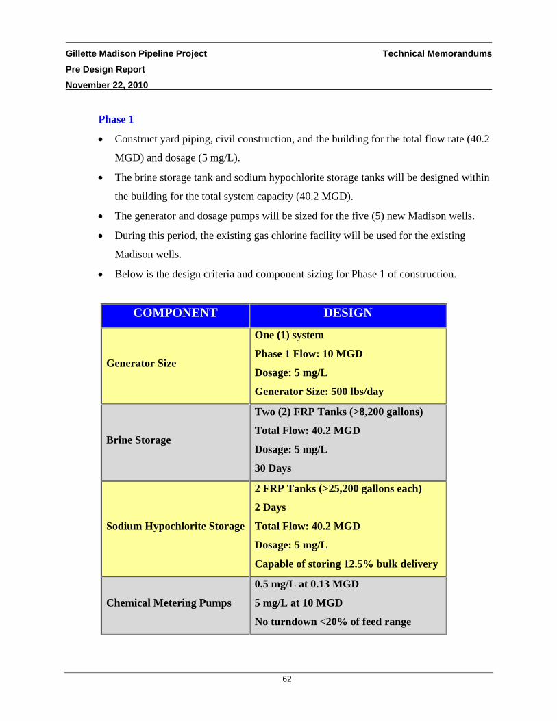
Gillette Madison Pipeline Project Technical Memorandums Pre Design Report November 22, 2010
62
Phase 1
• Construct yard piping, civil construction, and the building for the total flow rate (40.2
MGD) and dosage (5 mg/L).
• The brine storage tank and sodium hypochlorite storage tanks will be designed within
the building for the total system capacity (40.2 MGD).
• The generator and dosage pumps will be sized for the five (5) new Madison wells.
• During this period, the existing gas chlorine facility will be used for the existing
Madison wells.
• Below is the design criteria and component sizing for Phase 1 of construction.
COMPONENT DESIGN
Generator Size
One (1) system
Phase 1 Flow: 10 MGD
Dosage: 5 mg/L
Generator Size: 500 lbs/day
Brine Storage
Two (2) FRP Tanks (>8,200 gallons)
Total Flow: 40.2 MGD
Dosage: 5 mg/L
30 Days
Sodium Hypochlorite Storage
2 FRP Tanks (>25,200 gallons each)
2 Days
Total Flow: 40.2 MGD
Dosage: 5 mg/L
Capable of storing 12.5% bulk delivery
Chemical Metering Pumps
0.5 mg/L at 0.13 MGD
5 mg/L at 10 MGD
No turndown <20% of feed range

Gillette Madison Pipeline Project Technical Memorandums Pre Design Report November 22, 2010
63
Phase 2
• Upon decommissioning of the Madison gas chlorine system the on-site sodium
hypochlorite system will be used for the disinfection of the existing Madison wells
along with the five (5) new Madison wells for a total flow rate of 21.2 MGD.
• One additional 500 lb/day sodium hypochlorite generation system skid would used to
produce the required amount of sodium hypochlorite.
• Additional chemical pumps would be added to the system for a flow rate of 21.2
MGD at a dosage of 5 mg/L.
• No additional storage would be required since it was sized for the total capacity in
Phase 1.
Phase 3
• Upon completion of the remaining new Madison wells, the disinfection system will
need to be capable of a total flow rate of 40.2 MGD at a dosage of 5 mg/L.
• An additional 700 lb/day generation system skid would used to produce the required
amount of sodium hypochlorite.
• Additional chemical pumps would be added to the system for a flow rate of 40.2
MGD at a dosage of 5 mg/L.
• No additional storage would be required since it was sized for the total capacity in
Phase 1.
* * * * *

Gillette Madison Pipeline Project Summary Pre Design Report November 22, 2010
64
4.0 SUMMARY
The previous sections describe the Technical Memorandums that have been finalized for this Pre
Design Report. The TM’s each provide recommendations and conclusions for the facilities that
will be designed under the GMPP. The attached exhibit provides a visual for the location of
these recommendations and is labeled according to which Technical Memorandums apply.
Section 2 provides a summary of the scope required under the Pre-Design report along with a
check list of where each scope item is addressed for easy reference by the COG and WWDC.
Results from the Pre-Design report have already been incorporated into the 10% designs for the
GMPP facilities and will serve as the basis of design as the design team moves into the 50% and
90% design phases.
* * * * *

APPENDIX A – TECHNICAL MEMORANDUMS 1 THROUGH 13

APPENDIX B – ENGINEERS OPINION OF PROBABLE COST ESTIMATES