giddings & lewis · giddings & lewis centurion dsm drives and motors motion solutions...
TRANSCRIPT
CENTURION DSM DRIVES AND MOTORS
MOTION SOLUTIONS PRODUCT GUIDE
Giddings & Lewis
Material Number M.1301.4207Version 1.0

Centurion DSM Drives and MotorsMotion Solutions Product Guide
NOTE
Progress is an ongoing commitment at Giddings & Lewis. We continually strive to offer the most advanced products in the industry; therefore, information in this document is subject to change without notice. The illustrations and specifications are not binding in detail. Giddings & Lewis shall not be liable for any technical or editorial omissions occurring in this document, nor for any consequential or incidental damages resulting from the use of this document.
DO NOT ATTEMPT to use any Giddings & Lewis product until the use of such product is completely understood. It is the responsibility of the user to make certain proper operation practices are understood. Giddings & Lewis products should be used only by qualified personnel and for the express purpose for which said products were designed.
Should information not covered in this document be required, contact the Customer Service Department, Giddings & Lewis, 660 South Military Road, P.O. Box 1658, Fond du Lac, WI 54936-1658. Giddings & Lewis can be reached by telephone at 920 921 7100.
Version 1.0
Copyright © 2002 Giddings & Lewis, LLC
ADeviceNet is a trademark of Iris Technologies, Inc.IBM is a trademark of International Business Machines Corp.IEEE is a trademark of the Institute of Electrical and Electronics EngineersNEMA is a trademark of the National Energy Manufacturers AssociationPentium is a trademark of Intel CorporationWindows 95, Windows 98, Windows NT, MS-DOS, QuickBASIC, and Microsoft are trademarks of Microsoft CorporationPiC900, PiC90, PiCPro, PiCServoPro, PiCMicroTerm, Centurion, and MMC are trademarks of Giddings & Lewis, LLC

Table of Contents:Centurion™ DSM Drives and Motors Product Guide
Centurion™ DSM Drives, Motors, and Accessories .................................................. 1DSM100 - Digital Servo Drives ................................................................................ 3
DSM100 Drive Features ................................................................................... 5DSM 100 Dimensions ....................................................................................... 6Micro DSM Drive Features .............................................................................. 8
Optional SERCOS Feature for DSM100 Drives ....................................................... 10Optional Positioning Feature for DSM100 and MicroDSM Drives .......................... 12DSMPro ..................................................................................................................... 16DSM100 Specifications (Standard Drives) ................................................................ 21Micro DSM Specifications ........................................................................................ 24DSM100 With NSM Series Motors ........................................................................... 27DSM100 With YSM Series Motors ........................................................................... 29DSM100 With HSM Series Motors ........................................................................... 31DSM100 With FSM Series Motors ........................................................................... 35Cables and Accessories .............................................................................................. 38DSM Options and Accessories .................................................................................. 43
Touch Pad ......................................................................................................... 43AC Line Filters ................................................................................................. 44External Shunt Resistor Kit for DSM110, 120, and 130 .................................. 46Shunt Resistor Kit for MicroDSM Drives DSM007, DSM015 and DSM030 . 46
DSM100 Terminal Convertors .................................................................................. 47J1 Screw Terminal Convertor ........................................................................... 47J2 Screw Terminal Convertor ........................................................................... 48
SERCOS Fiber Optic Cables ..................................................................................... 49Centurion Brushless Servo Motors - General ............................................................ 50NSM Brushless Servo Motors ................................................................................... 51
NSM Series Motor And Performance Data ...................................................... 52NSM Motor Dimensions ................................................................................... 54NSM Motor Encoder Data ................................................................................ 55NSM Motor Connector and Ordering Options ................................................. 57
YSM Brushless Servo Motors .................................................................................. 58YSM Motors And Performance Data ............................................................... 59YSM Standard Motor Dimensions ................................................................... 60YSM Motor and Connector Ordering Information ........................................... 61
FSM Medium Inertia Brushless Servo Motors .......................................................... 62FSM Motor And Performance Data .................................................................. 63FSM Motor And Connector Ordering Information .......................................... 65
Giddings & Lewis Centurion DSM Drives and Motors Motion Solutions Product Guide -i

HSM Low Inertia Brushless Servo Motors ................................................................ 66HSM Motor And Performance Data ................................................................. 67HSM Motor And Performance Data (Continued) ............................................. 68HSM Standard Motor Dimensions ................................................................... 69HSM Motor And Connector Ordering Information .......................................... 70
Application Guidelines For HSM, FSM, YSM, NSM Brake Motors ........................ 71Brake Data For HSM and FSM Motors ..................................................................... 73Standard Motor Radial Load Force Ratings For HSM and FSM Motors .................. 74
-ii Centurion DSM Drives and Motors Motion Solutions Product Guide Giddings & Lewis

MOTION SOLUTIONS PRODUCT GUIDE
Centurion™ DSM Drives, Motors, and Accessories


DSM100 - Digital Servo Drives
DSM100 - Digital Servo Drives
The Giddings & Lewis Centurion DSM line is a family of versatile universal drives. These feature-rich, high performance drives offer flexibility in a wide range of applications. The DSM is called a universal drive because of its ability to run both brushless servo motors and induction motors and because of its ability to act as an analog input velocity servo, variable speed drive, stepper drive replacement or master encoder follower complete with electronic gearing. The Windows based interface, DSMPro, provides you with a powerful configuration and diagnostic tool to improve your productivity when integrating DSM Drives into your machine. The common cabling, functionality and interface throughout the DSM family will drive down your life cycle costs when you standardize on the Centurion DSM drives.
CPUCSM
Setup and CommunicationsRS232/485
I/O24V I/O
Command
Touch Pad
DSMPro
Smart Host
Motor Power
Enco
der
AC In
put
DOS basedpersonal computer
with Microsoft Windows
To u c h P a d
S m a rt H o st
P ers on a l C om pu te r
Giddings & Lewis Centurion DSM Drives and Motors Motion Solutions Product Guide 3
DSM100 - Digital Servo Drives
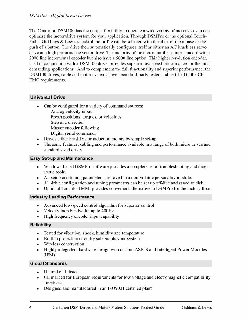
The Centurion DSM100 has the unique flexibility to operate a wide variety of motors so you can optimize the motor/drive system for your application. Through DSMPro or the optional Touch-Pad, a Giddings & Lewis standard motor file can be selected with the click of the mouse or the push of a button. The drive then automatically configures itself as either an AC brushless servo drive or a high performance vector drive. The majority of the motor families come standard with a 2000 line incremental encoder but also have a 5000 line option. This higher resolution encoder, used in conjunction with a DSM100 drive, provides superior low speed performance for the most demanding applications. And to complement the full functionality and superior performance, the DSM100 drives, cable and motor systems have been third-party tested and certified to the CE EMC requirements.
• Can be configured for a variety of command sources:Analog velocity input Preset positions, torques, or velocities Step and direction Master encoder followingDigital serial commands
• Drives either brushless or induction motors by simple set-up• The same features, cabling and performance available in a range of both micro drives and
standard sized drives
• Windows-based DSMPro software provides a complete set of troubleshooting and diag-nostic tools.
• All setup and tuning parameters are saved in a non-volatile personality module.• All drive configuration and tuning parameters can be set up off-line and saved to disk.• Optional TouchPad MMI provides convenient alternative to DSMPro for the factory floor.
• Advanced low-speed control algorithm for superior control• Velocity loop bandwidth up to 400Hz• High frequency encoder input capability
• Tested for vibration, shock, humidity and temperature• Built in protection circuitry safeguards your system• Wireless construction• Highly integrated hardware design with custom ASICS and Intelligent Power Modules
(IPM)
• UL and cUL listed• CE marked for European requirements for low voltage and electromagnetic compatibility
directives• Designed and manufactured in an ISO9001 certified plant
Universal Drive
Easy Set-up and Maintenance
Industry Leading Performance
Reliability
Global Standards
4 Centurion DSM Drives and Motors Motion Solutions Product Guide Giddings & Lewis
DSM100 - Digital Servo Drives
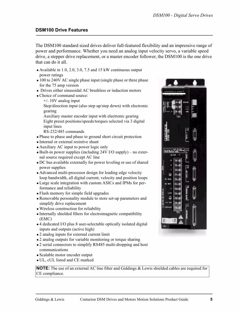
DSM100 Drive Features
The DSM100 standard sized drives deliver full-featured flexibility and an impressive range of power and performance. Whether you need an analog input velocity servo, a variable speed drive, a stepper drive replacement, or a master encoder follower, the DSM100 is the one drive that can do it all.•Available in 1.0, 2.0, 3.0, 7.5 and 15 kW continuous output
power ratings•100 to 240V AC single phase input (single phase or three phase
for the 75 amp version• Drives either sinusoidal AC brushless or induction motors •Choice of command source:
+/- 10V analog inputStep/direction input (also step up/step down) with electronic gearingAuxiliary master encoder input with electronic gearingEight preset positions/speeds/torques selected via 3 digital input linesRS-232/485 commands
•Phase to phase and phase to ground short circuit protection• Internal or external resistive shunt•Auxiliary AC input to power logic only•Built-in power supplies (including 24V I/O supply) – no exter-
nal source required except AC line•DC bus available externally for power leveling or use of shared
power supplies•Advanced multi-processor design for leading edge velocity
loop bandwidth, all digital current, velocity and position loops•Large scale integration with custom ASICs and IPMs for per-
formance and reliability•Flash memory for simple field upgrades•Removable personality module to store set-up parameters and
simplify drive replacement•Wireless construction for reliability• Internally shielded filters for electromagnetic compatibility
(EMC)•4 dedicated I/O plus 8 user-selectable optically isolated digital
inputs and outputs (active high)•2 analog inputs for external current limit•2 analog outputs for variable monitoring or torque sharing•2 serial connectors to simplify RS485 multi-dropping and host
communications•Scalable motor encoder output•UL, cUL listed and CE marked
NOTE: The use of an external AC line filter and Giddings & Lewis shielded cables are required for CE compliance.
Giddings & Lewis Centurion DSM Drives and Motors Motion Solutions Product Guide 5

DSM100 - Digital Servo Drives
DSM 100 Dimensions
DSM100 Dimensions (Standard Drives)DSM110, DSM120, DSM130, DSM175
C
A
A8
C1
A2
A3 B1B2
B3B
KEY mm (in)
DSM110 / 110PDSM120 / 120P DSM175,DSM130 / 130P DSM175P
A 360.6 (14.2) 360.6 (14.2)A1 332.7 (13.1) 332.7 (13.1)A2 349.3 (13.75) 349.3 (13.75)A3 6.4 (0.25) 6.9 (0.27)A4 27.9 (1.1) 27.9 (1.1)A5 35.6 (1.4) 35.6 (1.4)A6 101.6 (4.0) 101.6 (4.0)A7 124.5 (4.9) 124.5 (5.3)A8 8.9 (0.35) 8.9 (0.35)
B 104.1 (4.10) 151.7 (5.97)B1 26.7 (1.05) 50.5 (1.99)B2 25.4 (1.00) 25.4 (1.00)B3 25.4 (1.00) 25.4 (1.00)
C 226.8 (8.93) 224.5 (8.84)C1 17.0 (0.67) 17.0 (0.67)
A1
A7
A6
A5
A4
6 Centurion DSM Drives and Motors Motion Solutions Product Guide Giddings & Lewis

DSM100 - Digital Servo Drives
DSM1150
BB5
B4
A
B7
C
A2
B1
B6
DSM 1150 and DSM 1150Pmm (in)
A 360.7 (14.20)A1 331.5 (13.05)A2 349.0 (13.74)A3 6.86 (0.27)A4 33.02 (1.30A5 36.32 (1.43)A6 26.92 (1.06)A7 196.09 (7.72)A8 12.95 (0.51)B 203.20 (8.00)B1 31.70 (1.25)B4 69.80 (2.75)B5 139.7 (5.50)B6 31.70 (1.25)B7 139.70 (5.50)C 224.50 (8.84)C1 18.29 (0.72)
A1
A3C1
A8
A5
A6
A7
A4
Giddings & Lewis Centurion DSM Drives and Motors Motion Solutions Product Guide 7

DSM100 - Digital Servo Drives
Micro DSM Drive Features
The Micro DSM drives deliver full-featured flexibility and performance in a very compact size. This space-saving drive is also a time saver with its easy to use Windows-based DSMPro software tool. For superior performance in a variety of power ratings and sizes, the Micro DSM is the one drive that can do it all.
• Available in 0.5 kW, 1.0 kW and 2.0 kW continuous output power ratings
• Superior performance and functionality of larger drives in a package 1/4 of their size
• 100 to 240V AC single phase input• Choice of command source:
+/- 10V analog inputStep/direction input (also step up/step down) with electronic gearingAuxiliary master encoder input with electronic gearingEight preset positions/speeds/torques selected via 3 digital input linesRS-232/485 commands
• External active shunt available• Phase to phase and phase to ground short circuit protection• Drives sinusoidal AC brushless motors• DC bus available externally for power leveling • Advanced control algorithms for leading edge velocity loop
bandwidth. All current, velocity and position loops are digitalSpeed range 8000:1Velocity regulation +/-0.44 RPM with 5000 PPR encoder
• Large scale integration with custom ASICs and IPMs for per-formance and reliability
• Internally shielded output filter for electromagnetic compatibil-ity (EMC)
• 4 dedicated I/O plus 5 user-selectable optically isolated digital inputs and outputs (sourcing/active high)
• 1 analog input for external current limit• 1 analog output for variable monitoring or torque sharing• Serial port for RS232/485 host communications• Scalable motor encoder output• UL, cUL listed and CE marked
NOTE: The use of an external AC line filter, and Giddings & Lewis shielded cables are required for CE compliance.
8 Centurion DSM Drives and Motors Motion Solutions Product Guide Giddings & Lewis
DSM100 - Digital Servo Drives
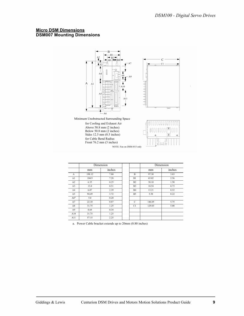
Micro DSM DimensionsDSM007 Mounting Dimensions
Dimension Dimensionmm inches mm inches
A 198.12 7.80 B 97.30 3.83A1 184.9 7.28 B1 65.02 2.56
A2 6.35 0.25 B2 38.10 1.50A3 13.0 0.51 B3 18.54 0.73
A4 6.07 2.39 B4 13.21 0.52A5 94.49 3.72 B5 5.58 0.22A6a
a. Power Cable bracket extends up to 20mm (0.80 inches)
5.0 0.20
A7 22.10 0.87 C 146.05 5.75A8 31.75 1.25 C1 129.03 5.08
A9 8.64 0.34A10 31.75 1.25A11 57.15 2.25
A1
A2
A3
A4
A6
A5
CC1
BB1B2
B4B3
A
A7
A8 A9
A10
A11
NOTE: Fan on DSM-015 only
Minimum Unobstructed Surrounding Spacefor Cooling and Exhaust AirAbove 50.8 mm (2 inches)Below 50.8 mm (2 inches)Sides 12.5 mm (0.5 inches)for Cable Bend RadiusFront 76.2 mm (3 inches)
Giddings & Lewis Centurion DSM Drives and Motors Motion Solutions Product Guide 9
Optional SERCOS Feature for DSM100 Drives
Optional SERCOS Feature for DSM100 Drives
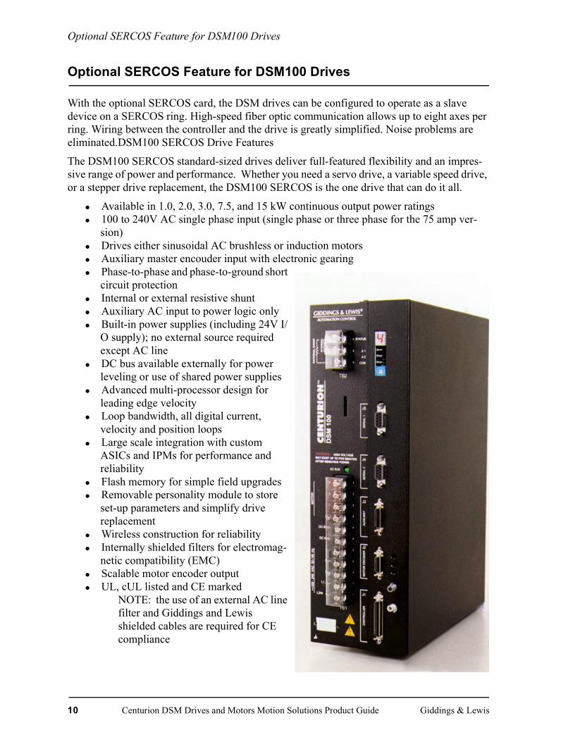
With the optional SERCOS card, the DSM drives can be configured to operate as a slave device on a SERCOS ring. High-speed fiber optic communication allows up to eight axes per ring. Wiring between the controller and the drive is greatly simplified. Noise problems are eliminated.DSM100 SERCOS Drive Features
The DSM100 SERCOS standard-sized drives deliver full-featured flexibility and an impres-sive range of power and performance. Whether you need a servo drive, a variable speed drive, or a stepper drive replacement, the DSM100 SERCOS is the one drive that can do it all.
• Available in 1.0, 2.0, 3.0, 7.5, and 15 kW continuous output power ratings• 100 to 240V AC single phase input (single phase or three phase for the 75 amp ver-
sion)• Drives either sinusoidal AC brushless or induction motors• Auxiliary master encouder input with electronic gearing• Phase-to-phase and phase-to-ground short
circuit protection• Internal or external resistive shunt• Auxiliary AC input to power logic only• Built-in power supplies (including 24V I/
O supply); no external source required except AC line
• DC bus available externally for power leveling or use of shared power supplies
• Advanced multi-processor design for leading edge velocity
• Loop bandwidth, all digital current, velocity and position loops
• Large scale integration with custom ASICs and IPMs for performance and reliability
• Flash memory for simple field upgrades• Removable personality module to store
set-up parameters and simplify drive replacement
• Wireless construction for reliability• Internally shielded filters for electromag-
netic compatibility (EMC)• Scalable motor encoder output• UL, cUL listed and CE marked
NOTE: the use of an external AC line filter and Giddings and Lewis shielded cables are required for CE compliance
10 Centurion DSM Drives and Motors Motion Solutions Product Guide Giddings & Lewis

Optional SERCOS Feature for DSM100 Drives
Other features which can be accessed through SERCOS IDNs:
• Four dedicated optically isolated digital inputs, which include two high-speed inputs for registration or probing
• Four dedicated optically isolated digital outputs• Two relay outputs• Three analog inputs for monitoring feedback from dancer, tension, or pressure measur-
ing devices• Two analog inputs for variable monitoring, torque sharing, or controlling an open loop
spindle
Giddings & Lewis Centurion DSM Drives and Motors Motion Solutions Product Guide 11

Optional Positioning Feature for DSM100 and MicroDSM Drives
Optional Positioning Feature for DSM100 and MicroDSM Drives
With the optional positioning feature, the DSM drives can be configured to act as simple controllers for point-to-point positioning applications. The positioning feature includes:
• Built-in home routine• Position distance move• Position absolute move• Position registered distance move
Applications where this positioning capability could provide the motion control solution include:
OverviewThe positioning drives can be configured to execute up to eight different trapezoidal position moves initiated by the digital I/O, TouchPad, or an unlimited number of positions through the host command language. The position mode does not require a command source from a motion controller or PLC.
The drives are designed to support three different types of position moves:
• Incremental - Distance move executed relative to current position• Absolute - Position move executed in reference to the home position• Registration - Distance move executed relative to the registration sensor digital input
The positioning drives are capable of storing up to eight individual position moves. Additionally, a ninth ‘RAM’ position move exists for use with the serial host command language. This allows you to continually download new parameter information. The drives are designed to provide maximum flex-ibility by allowing you to define the following parameters for each individual position move:
• Position Type - Incremental, Absolute, or Registration• Distance (Position) - Value indicates the length of travel or position (for absolute position) for
the position move• Batch Count - Determines the number of times the position will automatically execute. A
value of zero will execute the move continuously.• Dwell Time - Sets the length of time the drive will hold position between execution periods.• Registration Distance - Determines the relative length of travel the drive will execute after the
registration sensor digital input is detected. Registration distance is only active if a registration position type is selected.
• Velocity - Sets the commanded velocity the drive will use when executing the position move• Acceleration - Value used as the rate of speed increase during execution of the position move• Deceleration - Value used as the rate of speed decrease during execution of the position move• Action When Complete - Allows you to configure the drive to start a different position move
when the current move has completed its execution. You can create a series of position moves to execute automatically (or with a Start Index Input), reducing the need to use the Preset Select Inputs.
Rotary Tables Feed-to-Length Pick and Place Machines
Material Feeders Roll Stock Processors Wafer Handling Machines
Material Handling Lane Diverters Wire-Cutting Operations
Intelligent Conveyors Punch Press Clutch-Brake Replacements
Intelligent Setup Axis Pneumatic Cylinder Replacements
12 Centurion DSM Drives and Motors Motion Solutions Product Guide Giddings & Lewis
Optional Positioning Feature for DSM100 and MicroDSM Drives
Home Routine with Positioning DrivesThe home routine in the positioning drives allows you to home the axis without the use of a supervi-sory device. Using DSMPro, you can select a home routine to satisfy your application.
1. Home to Sensor/Then Marker - When the home routine is initiated, the drive will accelerate the motor to the defined homing velocity and look for the sensor/switch assigned to digital input #2. After the switch is seen, the drive defines the next marker (encoder index pulse) as the home posi-tion.
2. Home to Marker - When the home routine is initiated, the drive will define the next marker pulse as the home position.
3. Home to Sensor - When the home routine is initiated, the drive will define the input assigned at input #2 as the home position.
For all types of homing, an Offset Move Distance can also be defined which will move the axis the specified distance from the home marker and define that new position as the home position.
You can define the following parameters for the home routine:
• Homing Type - Home to sensor/then marker, home to marker, home to sensor • Homing Velocity - Velocity at which the home routine will execute• Homing Accel/Decel - Acceleration and deceleration values used in the home routine• Offset Move Distance - User specified distance the axis moves relative to the home marker.
The final destination then becomes the home position.• Home Position - Defines the home position to any value• Auto-Start Homing - If the auto-start homing box is checked in DSMPro, the home routine
will execute automatically on the first enable or on a hard reset. You can also initiate the home routine by using the ‘Start Homing’ assignable digital input.
Digital I/O and Positioning DrivesThe positioning mode of operation requires the use of the assignable digital I/O or the serial host com-mand language. The DSM drives have the following assignable digital inputs/outputs available.
Number of assignable optically isolated digital
Inputs Outputs
MicroDSM - DSM007, 015, 030 3 (4*) 2
Standard DSM - DSM110, 120, 130, 175, 1150 4 (5*) 4
*The release of positioning redefines the dedicated fault reset digital input to be assignable. This provides you with another available input for posi-tioning.
Giddings & Lewis Centurion DSM Drives and Motors Motion Solutions Product Guide 13
Optional Positioning Feature for DSM100 and MicroDSM Drives
Host Mode Control with Positioning DrivesThe positioning mode of operation, like the other operating modes, is designed to be useful within a serial host control environment. A special ‘RAM’ position whose parameters are not stored in non-vol-atile memory may be used for host positioning control when position parameters require continual changing. The ‘RAM’ position and non-volatile memory position parameters are all configurable through the host command language. The host may also override the digital input controls to force host mode control and initiate all positioning through the host command language.
DSMPro with Positioning Drives DSMPro version 1.4 or higher is required for use with the positioning drives. Drive parameter files created with non-positioning drives cannot be used with positioning drives and vice versa.
Touch Pad with Positioning DrivesAll positioning parameters may be configured through the use of the five-key, eight character Touch-Pad. A ‘Start Index’ and a ‘Start Homing’ capability is also available on the TouchPad.
Additional Drive FeaturesThese features have also been added to the DSM drives.
• Flash EPROM in MicroDSM Drives - provides the ability to field download new firmware revisions in MicroDSM drives as previously provided in the standard DSM drives.
• Reduction in Voltage Required in MicroDSM Drives - The positioning drives require an input voltage of 11 to 28V to operate the digital I/O.
• Analog Position Operation Mode - An analog position mode allows position control of the motor based on an analog ±10V input. This operation mode will be useful in high performance valve applications that require the use of an accurate servo control.
Part Numbers for Positioning Drives
Drive Part Number
DSM007P M.1016.1627 (old # 401-56451-50)
DSM015P M.1016.1629 (old # 401-56452-50)
DSM030P M.1016.1631 (old # 401-56453-50)
DSM110P M.1015.7919 (old # 401-34400-50)
DSM120P M.1015.7921 (old # 401-34401-50)
DSM130P M.1015.7923 (old # 401-34402-50
DSM175P M.1015.7925 (old # 401-34403-50)
DSM1150P M.1015-7927 (old # 401-34404-50)
14 Centurion DSM Drives and Motors Motion Solutions Product Guide Giddings & Lewis
Host ModeThe DSM100’s Host Command protocol provides optional drive configuration using the drive’s Serial Communications Interface. This powerful feature allows your controller to access all of the drive’s digital controls using sequences of ASCII characters. The protocol includes error checking to ensure the integrity of the transmitted commands.
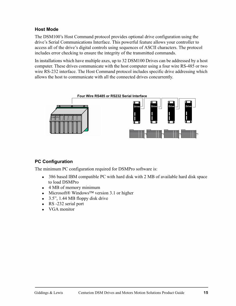
In installations which have multiple axes, up to 32 DSM100 Drives can be addressed by a host computer. These drives communicate with the host computer using a four wire RS-485 or two wire RS-232 interface. The Host Command protocol includes specific drive addressing which allows the host to communicate with all the connected drives concurrently.
PC ConfigurationThe minimum PC configuration required for DSMPro software is:
• 386 based IBM compatible PC with hard disk with 2 MB of available hard disk space to load DSMPro
• 4 MB of memory minimum• Microsoft® Windows™ version 3.1 or higher• 3.5”, 1.44 MB floppy disk drive• RS -232 serial port• VGA monitor
DRIVE DRIVE DRIVE DRIVE
Four Wire RS485 or RS232 Serial Interface
CPUCSM
Drive Drive Drive Drive
Giddings & Lewis Centurion DSM Drives and Motors Motion Solutions Product Guide 15

DSMPro
DSMPro
DSMPro is a convenient point-and-click software interface for customizing the features in the Centurion DSM100 drives to best fit your application. Suitable for any PC with Windows, it is used to configure, monitor, and troubleshoot a servo system. The on-line help and quick star-tup windows will simplify your setup while tools such as the on-screen digital oscilloscope provide simplified tuning and diagnosis. It also provides a full array of on-screen meters and other software tools for rapid debugging and measurement. DSMPro keeps error messages in its own non-volatile message buffer to save time in tracking down a problem. And in systems with multiple drives, DSMPro can simultaneously display status and configuration screens for all drives that are on an RS485 or RS232 link. DSMPro can also be used off-line to configure a drive and save the set-up to disk for later downloading to a drive.
DSMPro Drive WindowThe Drive Window becomes active after communications with a drive are established or DSMPro enters the off-line mode.
The Drive Window is the main window for performing functions in DSMPro. It is a function-ally easy method to visually setup, run, evaluate and diagnose one or more servo systems. The commands available in DSMPro are described on the following pages.
The Drive Window displays icon buttons that access functions and parameters for individual drives.
Icon buttons are arranged in rows by drive functions:
Setup and Control
Displays
Diagnostics
16 Centurion DSM Drives and Motors Motion Solutions Product Guide Giddings & Lewis

DSMPro
DSMPro Sample ScreensDSMPro has a complete set of easy to understand windows available from its pull down menus. Examples of DSMPro screens are shown below. (The examples shown are using a Centurion DSM100 drive.)
Drive Setup
Drive Parameters
This Drive Set Up dialog box is automatically displayed when DSM-Pro is connected to an uninitialized drive. Usually, the only parameter requiring selection is the motor model number for operation with the drive.
The Drive Parameters window accesses common operating parameters for the drive including the command source, current limits, and fault thresholds. This window, along with the I/O Configura-tion window, defines the necessary drive parameters for an application.
Giddings & Lewis Centurion DSM Drives and Motors Motion Solutions Product Guide 17
DSMPro
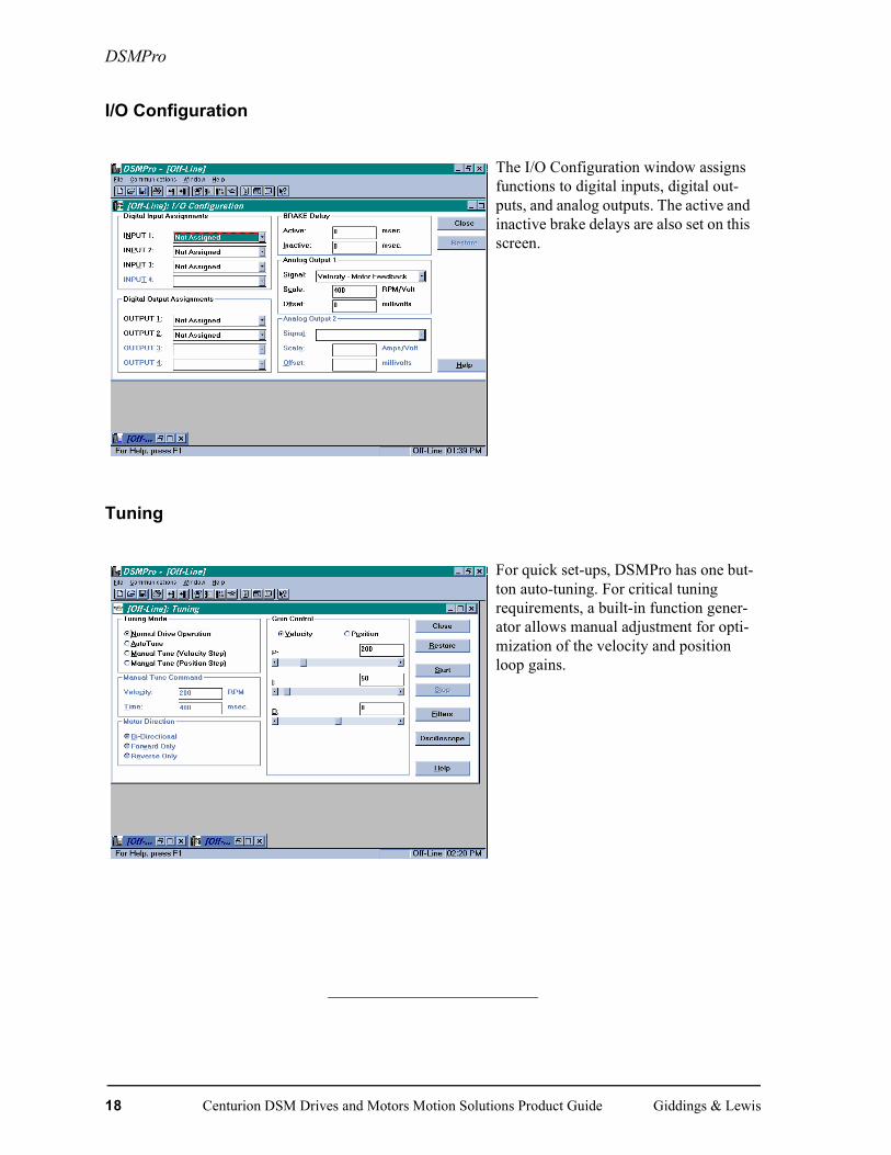
I/O Configuration
Tuning
The I/O Configuration window assigns functions to digital inputs, digital out-puts, and analog outputs. The active and inactive brake delays are also set on this screen.
For quick set-ups, DSMPro has one but-ton auto-tuning. For critical tuning requirements, a built-in function gener-ator allows manual adjustment for opti-mization of the velocity and position loop gains.
18 Centurion DSM Drives and Motors Motion Solutions Product Guide Giddings & Lewis

DSMPro
Oscilloscope
Diagnostics
The digital oscilloscope provides on-line monitoring of any drive parameter. Its functions include positive and nega-tive triggering, continuous tracing, A vs. B display and independent channel scaling and offset.
The Diagnostics screens provide fast verification of various I/O conditions and allow you to check functions and machine wiring by exercising the digital outputs.
A fault history provides complete infor-mation on past conditions and a fault check screen provides instant status on any error conditions.
Part Number
M.1017.0586 (old # 502-60036-00)
Included on PiCPro for Windows Applications CD
Giddings & Lewis Centurion DSM Drives and Motors Motion Solutions Product Guide 19

DSMPro
TouchPadThe TouchPad is a convenient alternative to using DSMPro for drive set-up and monitoring. The small TouchPad module plugs directly into the front of the drive where its eight character dot matrix display and five keys provide access to almost all the same functions avail-able in DSMPro.
The TouchPad is an excellent diagnostic and monitoring tool for use on the factory floor. One TouchPad can support several drives because it is independent of the drive and can be quickly attached and removed.
TouchPad CommandsCommands are entered by pressing a single key or combination of keys. Two modes of operation are available. Display mode allows you to move through the TouchPad Command tree to each parame-ter. Modify mode allows you to monitor and change each parameter. Most parameters can be modified or viewed while the drive is either running or disabled.
Part Number
M.1015.7928 (old # 401-34405-00)
TuneMode
20 Centurion DSM Drives and Motors Motion Solutions Product Guide Giddings & Lewis

DSM100 Specifications (Standard Drives)
DSM100 Specifications (Standard Drives)
Characteristic Specifications
Part Number
DSM110 M.1015.7918 (old # 401-34400-00)
DSM120 M.1015.7920 (old # 401-34401-00)
DSM130 M.1015.7922 (old # 401-34402-00)
DSM175 M.1015.7924 (old # 401-34403-00)
DSM1150 M.1015.7926 (old # 401-34404-00)
GeneralDSM110 DSM120 DSM130 DSM175 DSM175 DSM1150
(1φ input) (3φ input) (3φ input)
Peak Output Current (Amps) 10 20 30 50 75 150
Continuous Output Current (Amps) 5 10 15 15 35 65
Continuous Output Power (kW) 1.0 2.0 3.0 3.0 7.5 15.0
Continuous Shunt Power 50 W 50 W 50 W 50 W 50 W 180W
Peak Shunt Power 4.5 kW 4.5 kW 4.5 kW 10.0 kW 10.0 kW 19.0 kW
Continuous Shunt Power External (max.)
2.4 kW 2.4 kW 2.4 kW 4.0 kW 4.0 kW 8.0 kW
Peak Shunt Power External (max.) 6.0 kW 6.0 kW 6.0 kW 10.0 kW 10.0 kW 19.0 kW
Input
Continuous Input Current (Amps) 10 19 28 28 28 46
Input Voltage 100 to 240V AC RMS nominal
Input Frequency 47-63 Hz
Command Sources
Analog Velocity Input +/- 10 Volt
Presets 8 presets, binary selection by digital inputs
Step and direction, Step Up/Step Down
1 MHz maximum frequencyDifferential or single ended line drivers
Master Encoder Following 1 MHz maximum line frequency
Differential or single ended line drivers
Digital Serial Commands Via serial port and DSM host language
Giddings & Lewis Centurion DSM Drives and Motors Motion Solutions Product Guide 21

DSM100 Specifications (Standard Drives)
Serial Communication Port
Type RS-232, four-wire RS-485
Baud Rate 1200 to 19,200 baud
Multiple Drive Addressing Up to 32 drives, 10 using front panel rotary dip switch
Control Loops
Modes Torque, velocity and position control
Type All loops digital
Velocity Loop bandwidth (maximum) 400 Hz
Inputs and Outputs
Selectable Digital Inputs 4 optically isolated, 24 Volt, active high
User-selectable as: Drive Mode Select, Integrator Inhibit, Fol-lower Enable, Forward Enable, Reverse Enable, Preset Select, Analog Override
Selectable Digital Outputs 2 optically isolated, 24 Volt, active high, short circuit pro-tectedUser-selectable as: In Position, Within Position Window, Zero Speed, Within Speed Window, At Speed, Current Limit, Drive Enable, Bus Charged, various fault indications
Dedicated Digital Inputs Enable, Fault Reset (Optically isolated, 24 Volt, active high)
Dedicated Relay Outputs Ready/Not Faulted, Brake Output
Analog Inputs 1 external analog current limit, 0 to 10 Volt
Analog Outputs 1 user programmable, +/- 10 Volt
Encoder Output 1 MHz maximum line frequency Differential Line DriversScalable by 1, 1/2, 1/4, 1/8
Motor Feedback Incremental encoder
22 Centurion DSM Drives and Motors Motion Solutions Product Guide Giddings & Lewis
DSM100 Specifications (Standard Drives)
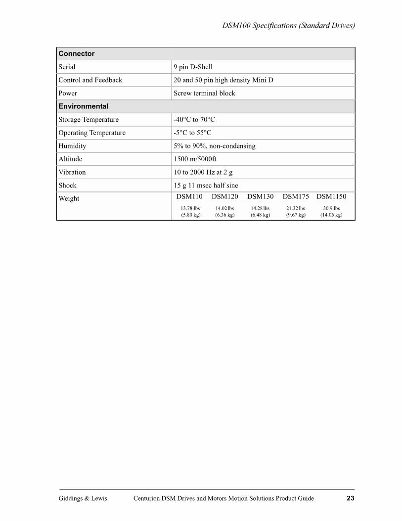
Connector
Serial 9 pin D-Shell
Control and Feedback 20 and 50 pin high density Mini D
Power Screw terminal block
Environmental
Storage Temperature -40°C to 70°C
Operating Temperature -5°C to 55°C
Humidity 5% to 90%, non-condensing
Altitude 1500 m/5000ft
Vibration 10 to 2000 Hz at 2 g
Shock 15 g 11 msec half sine
Weight DSM110 DSM120 DSM130 DSM175 DSM115013.78 lbs 14.02 lbs 14.28 lbs 21.32 lbs 30.9 lbs (5.80 kg) (6.36 kg) (6.48 kg) (9.67 kg) (14.06 kg)
Giddings & Lewis Centurion DSM Drives and Motors Motion Solutions Product Guide 23

Micro DSM Specifications
Micro DSM Specifications
Characteristic Specifications
Part Number
DSM007 M.1016.1626 (old # 401-56451-00)
DSM015 M.1016.1628 (old # 401-56452-00)
DSM030 M.1016.1630 (old # 401-56453-00)
General DSM007 DSM015 DSM030
Peak Output Current (Amps) 7.5 15 30
Continuous Output Current (Amps) 2.5 5 10
Continuous Output Power (kW) 0.5 1.0 2.0
Continuous Shunt Power External (with external shunt kit)1
300 W 300 W 300 W
Peak Shunt Power External (with exter-nal shunt kit) 1
2.2 kW 2.2 kW 2.2 kW
Input
Continuous Input Current (Amps) 5 9 18
Input Voltage 100 to 240V AC RMS nominal
Input Frequency 47-63 Hz
Command Sources
Analog Velocity Input +/- 10 Volt
Presets 8 presets, binary selection by digital inputs
Step and direction, Step Up/Step Down 1 MHz maximum frequencyDifferential or single ended line drivers
Master Encoder Following 1 MHz maximum line frequency
Differential or single ended line drivers
Digital Serial Commands Via serial port and DSM Drive host language
24 Centurion DSM Drives and Motors Motion Solutions Product Guide Giddings & Lewis

Micro DSM Specifications
Serial Communication Port
Type RS-232, four-wire RS-485
Baud Rate 1200 to 19,200 baud
Multiple Drive Addressing Up to 32 drives
Control Loops
Modes Torque, velocity and position control
Type All loops digital
Velocity Loop bandwidth (maximum) 300 Hz
Inputs and Outputs
Selectable Digital Inputs 3 optically isolated, 24 Volt, active highUser-selectable as: Drive Mode Select, Integrator Inhibit, Follower Enable, Forward Enable, Reverse Enable, Preset Select, Analog Override
Selectable Digital Outputs 2 optically isolated, 24 Volt, active high, short circuit pro-tectedUser-selectable as: In Position, Within Position Window, Zero Speed, Within Speed Window, At Speed, Current Limit, Drive Enable, Bus Charged, various fault indica-tions
Dedicated Digital Inputs Enable, Fault Reset (Optically isolated, 24 Volt, active high)
Dedicated Relay Outputs Ready/Not Faulted, Brake Output
Analog Inputs 1 external analog current limit, 0 to 10 Volt
Analog Outputs 1 user programmable, +/- 10 Volt
Encoder Output 1 MHz maximum line frequency Differential Line DriversScalable by 1, 1/2, 1/4, 1/8
Motor Feedback Incremental encoder
Giddings & Lewis Centurion DSM Drives and Motors Motion Solutions Product Guide 25
Micro DSM Specifications
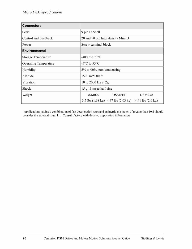
1Applications having a combination of fast deceleration rates and an inertia mismatch of greater than 10:1 should consider the external shunt kit. Consult factory with detailed application information.
Connectors
Serial 9 pin D-Shell
Control and Feedback 20 and 50 pin high density Mini D
Power Screw terminal block
Environmental
Storage Temperature -40°C to 70°C
Operating Temperature -5°C to 55°C
Humidity 5% to 90%, non-condensing
Altitude 1500 m/5000 ft.
Vibration 10 to 2000 Hz at 2g
Shock 15 g 11 msec half sine
Weight DSM007 DSM015 DSM030
3.7 lbs (1.68 kg) 4.47 lbs (2.03 kg) 4.41 lbs (2.0 kg)
26 Centurion DSM Drives and Motors Motion Solutions Product Guide Giddings & Lewis

DSM100 With NSM Series Motors
DSM100 With NSM Series Motors
Choose a system with an NSM Series motor when the application requires low cost and medium inertia. Cable part numbers shown are for straight cable. Some connectors are also available in right angle
DSM007/NSM2302 @ 115VAC
DSM007/NSM2304 @ 115VAC
DSM015/NSM3406 @ 230VAC
DSM015/NSM3412 @ 230VAC
DSM015/NSM4214 @ 230VAC
Detailed Motor Information Located in Brushless Motor SectionSystem Speed Torque Characteristics = Intermittent Operating Region *Last two digits select standard cable lengths of: 10 ft. (3.0m) - 10,
25 ft. (7.7m) - 25, 50 ft. (15.0m) - 50, 75 ft. (23.0m) - 75, 100 ft. (31m) - 00
Drive Module Input Voltage = 230 VAC RMS = Continuous Operating Region
44.5
3.53
2.5
5
2
1.51
0.50
TORQUE(lb-in) TORQUE
(Nm)
0
.11
.23
.34
.45.51
0 1000 2000 3000 4000 5000 6000SPEED (RPM)
DRIVEM.1015.6946(old # 401-30234-01)
Encoder Feedback CableM.1015.6931, 32, 33, 34, 30 (old # 401-30231-XX*)
J1 to controller
Motor Power CableM.1015.6926,27, 28, 29, 25
DSM007M.1016.1626 (old # 401-56451-00)
NSM2302(old # 401-30230-XX*)
Motor
0
TORQUE(lb-in) TORQUE
(Nm)
0
.23
.91
.45
.696
10
12
2
4
8
14
1.13
1.36
0 1000 2000 3000 4000 5000 6000SPEED (RPM)
DRIVE
Encoder Feedback CableM.1015.6931, 32, 33, 34, 30 (old # 401-30231-XX*)
J1 to controller
DSM007M.1016.1626 (old # 401-56451-00)
NSM2304(old # 401-30230-XX*)
Motor Power CableM.1015.6926,27, 28, 29, 25
M.1015.6949(old # 401-30235-01)
Motor
0
TORQUE(lb-in) TORQUE
(Nm)
0
.23
.91
.45
.696
10
12
2
4
8
16
1.13
1.36
18
20
1.58
1.81
2.03
0 1000 2000 3000 4000 5000 6000SPEED (RPM)
DRIVE
Encoder Feedback CableM.1015.6931, 32, 33, 34, 30 (old # 401-30231-XX*)
J1 to controller
DSM015M.1016.1628 (old # 401-56452-00)
NSM3406
M.1015.6952(old # 401-30236-00)
Motor
(old # 401-30230-XX*)
Motor Power CableM.1015.6926,27, 28, 29, 25
00 1000 2000 3000 4000 5000 6000
TORQUE(lb-in) TORQUE
(Nm)
0
.57
2.26
1.13
1.70
SPEED (RPM)
15
25
30
5
10
20
35
2.83
3.39
40
3.96 DRIVE
Encoder Feedback CableM.1015.6931, 32, 33, 34, 30 (old # 401-30231-XX*)
J1 to controller
DSM015M.1016.1628 (old # 401-56452-00)
NSM3412(old # 401-30230-XX*)
Motor Power CableM.1015.6926,27, 28, 29, 25
M.1015.6955(old # 401-30237-00)
Motor
0
TORQUE(lb-in) TORQUE
(Nm)
0
.57
3.96
1.70
2.83
SPEED (RPM)
15
25
5
35
5.0945
0 1000 2000 3000 4000 5000
DRIVE
Encoder Feedback CableM.1015.6931, 32, 33, 34, 30 (old # 401-30231-XX*)
J1 to controller
DSM015M.1016.1628 (old # 401-56452-00)
NSM4214(old # 401-30230-XX*)
Motor Power CableM.1015.6926,27, 28, 29, 25
M.1015.6958(old # 401-30238-00)
Motor
Giddings & Lewis Centurion DSM Drives and Motors Motion Solutions Product Guide 27
DSM100 With NSM Series Motors
= Drive Operation with 115 VAC RMC Input Voltage NOTE: Serial interface cables cannot exceed 50 ft.
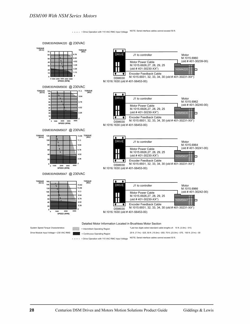
DSM030/NSM4220 @ 230VAC
DSM030/NSM5630 @ 230VAC
DSM030/NSM5637 @ 230VAC
DSM030/NSM5647 @ 230VAC
Detailed Motor Information Located in Brushless Motor SectionSystem Speed Torque Characteristics = Intermittent Operating Region *Last two digits select standard cable lengths of: 10 ft. (3.0m) - 010,
Drive Module Input Voltage = 230 VAC RMS = Continuous Operating Region 25 ft. (7.7m) - 025, 50 ft. (15.0m) - 050, 75 ft. (23.0m) - 075, 100 ft. (31m) - 00
= Drive Operation with 115 VAC RMC Input Voltage NOTE: Serial interface cables cannot exceed 50 ft.
0
TORQUE(lb-in) TORQUE
(Nm)
0
1.13
4.52
2.26
3.39
10
6.65
6.78
0 1000 2000 3000 4000 5000SPEED (RPM)
20
40
60
30
50
70DRIVE
Encoder Feedback CableM.1015.6931, 32, 33, 34, 30 (old # 401-30231-XX*)
J1 to controller
DSM030M.1016.1630 (old # 401-56453-00)
NSM4220(old # 401-30230-XX*)
Motor Power CableM.1015.6926,27, 28, 29, 25
M.1015.6960(old # 401-30239-00)
Motor
100
80
0
40
20
TORQUE(lb-in)
TORQUE(Nm)
0
2.26
4.52
9.04
6.78
11.3
0 1000 2000 3000 4000SPEED (RPM)
60
90
10
30
50
70 DRIVE
Encoder Feedback CableM.1015.6931, 32, 33, 34, 30 (old # 401-30231-XX*)
J1 to controller
DSM030M.1016.1630 (old # 401-56453-00)
NSM5630
M.1015.6962(old # 401-30240-00)
Motor
(old # 401-30230-XX*)
Motor Power CableM.1015.6926,27, 28, 29, 25
100
80
0
40
20
TORQUE(lb-in)
TORQUE(Nm)
0
2.26
4.52
9.04
6.78
11.3
0 1000 2000 3000 4000SPEED (RPM)
60
120 13.56
DRIVE
Encoder Feedback CableM.1015.6931, 32, 33, 34, 30 (old # 401-30231-XX*)
J1 to controller
DSM030M.1016.1630 (old # 401-56453-00)
NSM5637(old # 401-30230-XX*)
Motor Power CableM.1015.6926,27, 28, 29, 25
M.1015.6964(old # 401-30241-00)
Motor
140
120
0
40
20
TORQUE(lb-in)
TORQUE(Nm)
0
6.78
11.3
9.04
13.56
0 1000 2000 3000SPEED (RPM)
80
160
15.82
60
100
4.52
2.26
DRIVE
Encoder Feedback CableM.1015.6931, 32, 33, 34, 30 (old # 401-30231-XX*)
J1 to controller
DSM030M.1016.1630 (old # 401-56453-00)
NSM5647(old # 401-30230-XX*)
Motor Power CableM.1015.6926,27, 28, 29, 25
M.1015.6966(old # 401-30242-00)
Motor
28 Centurion DSM Drives and Motors Motion Solutions Product Guide Giddings & Lewis
DSM100 With YSM Series Motors
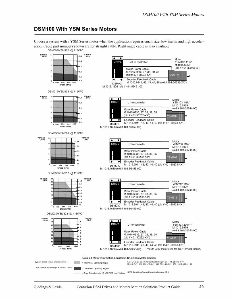
DSM100 With YSM Series Motors
Choose a system with a YSM Series motor when the application requires small size, low inertia and high acceler-ation. Cable part numbers shown are for straight cable. Right angle cable is also available
DSM007/YSM102 @ 115VAC
DSM015/YSM103 @ 115VAC
DSM030/YSM206 @ 115VAC
DSM030/YSM212 @ 115VAC
DSM030/YSM323 @ 115VAC**
Detailed Motor Information Located in Brushless Motor SectionSystem Speed Torque Characteristics = Intermittent Operating Region *Last two digits select standard cable lengths of: 10 ft. (3.0m) - 010
25 ft. (7.7m) - 025, 50 ft. (15.0m) - 050, 75 ft. (23.0m) - 075, 100 ft. (31m) - 00
Drive Module Input Voltage = 230 VAC RMS = Continuous Operating Region
= Drive Operation with 115 VAC RMC Input Voltage NOTE: Serial interface cables cannot exceed 50 ft.
5
4
0
2
1
TORQUE(lb-in)
TORQUE(Nm)
0.0
0.1
0.2
0.4
0.3
0.5
0 1000 2000 3000 4000SPEED (RPM)
3
DRIVE
Encoder Feedback CableM.1015.6941, 42, 43, 44, 40 (old # 401-30233-XX*)
J1 to controller
Motor Power CableM.1015.6936, 37, 38, 39, 35
DSM007M.1016.1626 (old # 401-56451-00)
YSM102(old # 401-30232-XX*)
M.1015.6968(old # 401-30243-00)
YSM102 115VMotor
10
8
0
4
2
TORQUE(lb-in)
TORQUE(Nm)
0.0
0.2
0.4
0.8
0.6
1.0
0 1000 2000 3000 4000SPEED (RPM)
6
DRIVE
Encoder Feedback CableM.1015.6941, 42, 43, 44, 40 (old # 401-30233-XX*)
J1 to controller
Motor Power CableM.1015.6936, 37, 38, 39, 35
DSM015M.1016.1628 (old # 401-56452-00)
YSM103(old # 401-30232-XX*)
M.1015.6969(old # 401-30244-00)
YSM103 115VMotor
20
16
0
8
4
TORQUE(lb-in)
TORQUE(Nm)
0.0
0.4
0.8
1.6
1.2
2.0
0 1000 2000 3000 4000SPEED (RPM)
12
DRIVE
Encoder Feedback CableM.1015.6941, 42, 43, 44, 40 (old # 401-30233-XX*)
J1 to controller
Motor Power CableM.1015.6936, 37, 38, 39, 35
DSM030M.1016.1630 (old # 401-56453-00)
YSM206(old # 401-30232-XX*)
M.1015.6971(old # 401-30245-00)
YSM206 115VMotor
40
0
20
10
TORQUE(lb-in)
TORQUE(Nm)
0.00.5
1.0
2.0
1.5
0 1000 2000 3000 4000SPEED (RPM)
30
5
15
25
35
2.5
3.0
3.54.0
DRIVE
Encoder Feedback CableM.1015.6941, 42, 43, 44, 40 (old # 401-30233-XX*)
J1 to controller
Motor Power CableM.1015.6936, 37, 38, 39, 35
DSM030M.1016.1630 (old # 401-56453-00)
YSM212(old # 401-30232-XX*)
M.1015.6972(old # 401-30246-00)
YSM212 115VMotor
70
60
0
20
10
TORQUE(lb-in)
TORQUE(Nm)
0 1000 2000 3000SPEED (RPM)
40
80
30
50
012
4
3
5
6
78
DRIVE
Encoder Feedback CableM.1015.6941, 42, 43, 44, 40 (old # 401-30233-XX*)
J1 to controller
Motor Power CableM.1015.6936, 37, 38, 39, 35
DSM030M.1016.1630 (old # 401-56453-00)
YSM323(old # 401-30232-XX*)
M.1015.6979(old # 401-30251-00)
YSM323 230V**Motor
**YSM 230V motor used for this 115V applicaiton.
Giddings & Lewis Centurion DSM Drives and Motors Motion Solutions Product Guide 29

DSM100 With YSM Series Motors
Centurion DSM100 With 230V YSM Series MotorsChoose a system with a YSM Series motor when the application requires small size, low inertia and high acceler-ation.
DSM007/YSM102 @ 230VAC
DSM007/YSM103 @ 230VAC
DSM015/YSM206 @ 230VAC
DSM015/YSM212 @ 230VAC
DSM030/YSM323 @ 230VAC
Detailed Motor Information Located in Brushless Motor SectionSystem Speed Torque Characteristics = Intermittent Operating Region *Last two digits select standard cable lengths of: 10 ft. (3.0m) - 010,
Drive Module Input Voltage = 230 VAC RMS = Continuous Operating Region 25 ft. (7.7m) - 025, 50 ft. (15.0m) - 050, 75 ft. (23.0m) - 075, 100 ft. (31m) - 00
= Drive Operation with 115 VAC RMC Input Voltage NOTE: Serial interface cables cannot exceed 50 ft.
5
4
0
2
1
TORQUE(lb-in)
TORQUE(Nm)
0.0
0.1
0.2
0.4
0.3
0.5
0 1000 2000 3000 4000SPEED (RPM)
3
DRIVE
Encoder Feedback CableM.1015.6941, 42, 43, 44, 40 (old # 401-30233-XX*)
J1 to controller
Motor Power CableM.1015.6936, 37, 38, 39, 35
DSM007M.1016.1626 (old # 401-56451-00)
YSM102(old # 401-30232-XX*)
M.1015.6972(old # 401-30247-00)
YSM102 230VMotor
10
8
0
4
2
TORQUE(lb-in)
TORQUE(Nm)
0.0
0.2
0.4
0.8
0.6
1.0
0 1000 2000 3000 4000SPEED (RPM)
6
DRIVE
Encoder Feedback CableM.1015.6941, 42, 43, 44, 40 (old # 401-30233-XX*)
J1 to controller
Motor Power CableM.1015.6936, 37, 38, 39, 35
DSM007M.1016.1626 (old # 401-56451-00)
YSM103(old # 401-30232-XX*)
M.1015.6972(old # 401-30248-00)
YSM103 230VMotor
20
16
0
8
4
TORQUE(lb-in)
TORQUE(Nm)
0.0
0.4
0.8
1.6
1.2
2.0
0 1000 2000 3000 4000SPEED (RPM)
12
DRIVE
Encoder Feedback CableM.1015.6941, 42, 43, 44, 40 (old # 401-30233-XX*)
J1 to controller
Motor Power CableM.1015.6936, 37, 38, 39, 35
DSM015M.1016.1628 (old # 401-56452-00)
YSM206(old # 401-30232-XX*)
M.1015.6975(old # 401-30249-00)
YSM206 230VMotor
40
0
20
10
TORQUE(lb-in)
TORQUE(Nm)
0.00.5
1.0
2.0
1.5
0 1000 2000 3000 4000SPEED (RPM)
30
5
15
25
35
2.5
3.0
3.54.0
DRIVE
Encoder Feedback CableM.1015.6941, 42, 43, 44, 40 (old # 401-30233-XX*)
J1 to controller
Motor Power CableM.1015.6936, 37, 38, 39, 35
DSM015M.1016.1628 (old # 401-56452-00)
YSM212(old # 401-30232-XX*)
M.1015.6977(old # 401-30250-00)
YSM212 230VMotor
50
0
40
20
TORQUE(lb-in)
TORQUE(Nm)
01
2
4
3
0 1000 2000 3000 4000SPEED (RPM)
70
10
30
60
80
5
6
78
DRIVE
Encoder Feedback CableM.1015.6941, 42, 43, 44, 40 (old # 401-30233-XX*)
J1 to controller
Motor Power CableM.1015.6936, 37, 38, 39, 35
DSM030M.1016.1630 (old # 401-56453-00)
YSM323(old # 401-30232-XX*)
M.1015.6979(old # 401-30251-00)
YSM323 230VMotor
30 Centurion DSM Drives and Motors Motion Solutions Product Guide Giddings & Lewis

DSM100 With HSM Series Motors
DSM100 With HSM Series Motors
Choose a system with an HSM Series motor when the application requires low inertia, high acceleration and peak torque. Cable part numbers shown are for straight cable. Some connectors are also available in right angle.
DSM015/HSM307 @ 230VAC
DSM030/HSM320 @ 230VAC
DSM030/HSM430 @ 230VAC
DSM110/HSM307 @ 230VAC
DSM120/HSM320 @ 230VAC
Detailed Motor Information Located in Brushless Motor SectionSystem Speed Torque Characteristics = Intermittent Operating Region *Last two digits select standard cable lengths of: 10 ft. (3.0m) - 10, 25 ft. (7.7m) - 25,
50 ft. (15.0m) - 50, 75 ft. (23.0m) - 75, 100 ft. (31m) - 00, 150 ft. (45m) 7X-00
Drive Module Input Voltage = 230 VAC RMS = Continuous Operating Region
00 1000 2000 3000 4000 5000
TORQUE(lb-in) TORQUE
(Nm)
0
0.5
2.0
1.0
1.5
SPEED (RPM)
6
1012
24
8
14
2.5
1618202224
0
TORQUE(lb-in) TORQUE
(Nm)
0
3
1
2
SPEED (RPM)
20
30
10
40
550
0 1000 2000 3000 4000 5000
4DRIVE
Encoder Feedback CableM.1015.7930, 31, 32, 33, 29 (old # 401-34407-XX*),
J1 to controller
Motor Power CableM.1015.7941, 43, 44, 45, 40
DSM030
(old # 401-34413-XX*)
M.1007.1091(old # 401-34433-00)
HSM320Motor
HSM320
M.1016.1630 (old # 401-56453-00) M.1015.7009 (old # 401-30271-00*)
80
0
40
20
TORQUE(lb-in)
TORQUE(Nm)
00 1000 2000 3000 4000
SPEED (RPM)
60
10
30
50
70
1234
5
678
9
DRIVE
Encoder Feedback CableM.1015.7930, 31, 32, 33, 29 (old # 401-34407-XX*),
J1 to controller
Motor Power CableM.1015.7947, 49, 50, 51, 46
DSM030
(old # 401-34414-XX*)
M.1015.7991(old # 401-34433-00)
HSM430Motor
HSM430
M.1016.1630 (old # 401-56453-00) M.1015.7009 (old # 401-30271-00*)
M.1015.7012 (old # 401-30273-00)
00 1000 2000 3000 4000 5000
TORQUE(lb-in) TORQUE
(Nm)
0
0.5
2.0
1.0
1.5
SPEED (RPM)
6
1012
24
8
14
2.5
1618202224
DRIVE
Encoder Feedback CableM.1015.7930, 31, 32, 33, 29 (old # 401-34407-XX*),
J1 to controller
Motor Power CableM.1015.7941, 43, 44, 45, 40
DSM110
(old # 401-34413-XX*)
M.1015.7985(old # 401-34432-00)
HSM307Motor
HSM307
M.1015.7918 (old # 401-34400-00) M.1015.7009 (old # 401-30271-00*)
0
TORQUE(lb-in) TORQUE
(Nm)
0
3
12
SPEED (RPM)
20
30
10
405
50
0 1000 2000 3000 4000 5000
4
60
70
67
DRIVE
Encoder Feedback CableM.1015.7930, 31, 32, 33, 29 (old # 401-34407-XX*),
J1 to controller
Motor Power CableM.1015.7940, 43, 44, 45, 40
DSM120
(old # 401-34413-XX*)
M.1015.7985(old # 401-34433-00)
HSM3207Motor
HSM320
M.1015.7920 (old # 401-34401-00) M.1015.7009 (old # 401-30271-00*)
DRIVE
Encoder Feedback CableM.1015.7930, 31, 32, 33, 29 (old # 401-34407-XX*),
J1 to controller
Motor Power CableM.1015.7941, 43, 44, 45, 40
DSM015
(old # 401-34413-XX*)
M.1015.7985(old # 401-34432-00)
HSM307Motor
HSM307
M.1016.1626 (old # 401-56452-00) M.1015.7009 (old # 401-30271-00*)
Giddings & Lewis. Centurion DSM Drives and Motors Motion Solutions Product Guide 31

DSM100 With HSM Series Motors
= Drive Operation with 115 VAC RMC Input Voltage NOTE: Serial interface cables cannot exceed 50 ft.
DSM120/HSM430 @ 230VAC
DSM130/HSM460 @ 230VAC
DSM130/HSM490 @ 230VAC
DSM175/HSM460 @ 230VAC
DSM175/HSM490 @ 230VAC
Detailed Motor Information Located in Brushless Motor SectionSystem Speed Torque Characteristics
= Intermittent Operating Region *Last two digits select standard cable lengths of: 10 ft. (3.0m) - 10, 25 ft. (7.7m) - 25,50 ft. (15.0m) - 50, 75 ft. (23.0m) - 75, 100 ft. (31m) - 00, 150 ft. (45m) 7X-00
80
0
40
20
TORQUE(lb-in)
TORQUE(Nm)
00 1000 2000 3000 4000
SPEED (RPM)
60
10
30
50
70
1234
5
678
9
DRIVE
Encoder Feedback CableM.1015.7930, 31, 32, 33, 29 (old # 401-34407-XX*),
J1 to controller
Motor Power CableM.1015.7940, 43, 44, 45, 40
DSM120
(old # 401-34414-XX*)
M.1015.7991(old # 401-34434-00)
HSM430Motor
HSM430
M.1015.7920 (old # 401-34401-00) M.1015.7009 (old # 401-30271-00*)
M.1015.7012 (old # 401-30273-00)
0
TORQUE(lb-in) TORQUE
(Nm)
02
SPEED (RPM)
20
40
60
0 1000 2000 3000 4000
4
80
100
120140
6
8
10
12
14DRIVE
Encoder Feedback CableM.1015.7930, 31, 32, 33, 29 (old # 401-34407-XX*),
J1 to controller
Motor Power CableM.1015.7940, 43, 44, 45, 40
DSM130
(old # 401-34414-XX*)
M.1015.7996(old # 401-34435-00)
HSM460Motor
HSM460
M.1015.7922 (old # 401-34402-00) M.1015.7009 (old # 401-30271-00*)
M.1015.7012 (old # 401-30273-00)
180
0
60
30
TORQUE(lb-in)
TORQUE(Nm)
0 1000 2000 3000SPEED (RPM)
120
90
150
03
6
12
9
15
18
21210
DRIVE
Encoder Feedback CableM.1015.7930, 31, 32, 33, 29 (old # 401-34407-XX*),
J1 to controller
Motor Power CableM.1015.7940, 43, 44, 45, 40
DSM130
(old # 401-34414-XX*)
M.1015.8001(old # 401-34436-00)
HSM490Motor
HSM490
M.1015.7922 (old # 401-34402-00) M.1015.7009 (old # 401-30271-00*)
M.1015.7012 (old # 401-30273-00)
TORQUE(lb-in) TORQUE
(Nm)
SPEED (RPM)0 1000 2000 3000 4000 0
3
6
12
9
15
18
21180
0
60
30
120
90
150
210
DRIVE
Encoder Feedback CableM.1015.7930, 31, 32, 33, 29 (old # 401-34407-XX*),
J1 to controller
Motor Power CableM.1015.7940, 43, 44, 45, 40
DSM175
(old # 401-34414-XX*)
M.1015.7996(old # 401-34435-00)
HSM490Motor
HSM460
M.1015.7924 (old # 401-34403-00) M.1015.7009 (old # 401-30271-00*)
M.1015.7012 (old # 401-30273-00)
240
0
80
40
TORQUE(lb-in)
TORQUE(Nm)
0 1000 2000 3000SPEED (RPM)
160
120
200
0
4
8
1612
20
24
28280
DRIVE
Encoder Feedback CableM.1015.7930, 31, 32, 33, 29 (old # 401-34407-XX*),
J1 to controller
Motor Power CableM.1015.7940, 43, 44, 45, 40
DSM175
(old # 401-34414-XX*)
M.1015.7996(old # 401-34436-00)
HSM490Motor
HSM490
M.1015.7924 (old # 401-34403-00) M.1015.7009 (old # 401-30271-00*)
M.1015.7012 (old # 401-30273-00)
32 Centurion DSM Drives and Motors Motion Solutions Product Guide Giddings & Lewis
DSM100 With HSM Series Motors
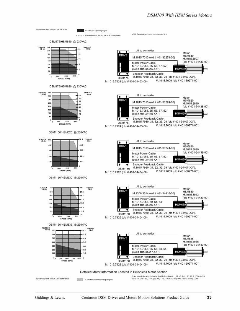
Drive Module Input Voltage = 230 VAC RMS = Continuous Operating Region
= Drive Operation with 115 VAC RMC Input VoltageNOTE: Serial interface cables cannot exceed 50 ft.
DSM175/HSM610 @ 230VAC
DSM175/HSM620 @ 230VAC
DSM1150/HSM620 @ 230VAC
DSM1150/HSM630 @ 230VAC
DSM1150/HSM835 @ 230VAC
Detailed Motor Information Located in Brushless Motor Section
System Speed Torque Characteristics = Intermittent Operating Region
*Last two digits select standard cable lengths of: 10 ft. (3.0m) - 10, 25 ft. (7.7m) - 25,50 ft. (15.0m) - 50, 75 ft. (23.0m) - 75, 100 ft. (31m) - 00, 150 ft. (45m) 7X-00
210
180
0
60
30
TORQUE(lb-in)
TORQUE(Nm)
0 1000 2000 3000SPEED (RPM)
120
240
90
150
0
5
10
20
25
15
DRIVE
Encoder Feedback CableM.1015.7930, 31, 32, 33, 29 (old # 401-34407-XX*),
J1 to controller
Motor Power CableM.1015.7953, 55, 56, 57, 52
DSM175
(old # 401-34415-XX*)
M.1015.8007(old # 401-34437-00)
HSM610Motor
HSM610
M.1015.7924 (old # 401-34403-00) M.1015.7009 (old # 401-30271-00*)
M.1015.7013 (old # 401-30274-00)
350
300
0
100
50
TORQUE(lb-in)
TORQUE(Nm)
0 1000 2000 3000SPEED (RPM)
200
400
150
250
0
1015
2520
5
3035
40
DRIVE
Encoder Feedback CableM.1015.7930, 31, 32, 33, 29 (old # 401-34407-XX*),
J1 to controller
Motor Power CableM.1015.7953, 55, 56, 57, 52
DSM175
(old # 401-34415-XX*)
M.1015.8010(old # 401-34438-00)
HSM620Motor
HSM620
M.1015.7924 (old # 401-34403-00) M.1015.7009 (old # 401-30271-00*)
M.1015.7013 (old # 401-30274-00)
400
0
100
TORQUE(lb-in)
TORQUE(Nm)
0
22.6
33.9
0 1000 2000 3000SPEED (RPM)
500
45.2
200
300
11.3
56.5
DRIVE
Encoder Feedback CableM.1015.7930, 31, 32, 33, 29 (old # 401-34407-XX*),
J1 to controller
Motor Power CableM.1015.7953, 55, 56, 57, 52
DSM1150
(old # 401-34415-XX*)
M.1015.8010(old # 401-34438-00)
HSM620Motor
HSM620
M.1015.7926 (old # 401-34404-00) M.1015.7009 (old # 401-30271-00*)
M.1015.7013 (old # 401-30274-00)
700
0
200
100
TORQUE(lb-in)
TORQUE(Nm)
0 1000 2000 3000SPEED (RPM)
400
300
600
0
22.6
45.2
33.9
11.3
56.5
67.8
79.1
500
DRIVE
Encoder Feedback CableM.1015.7930, 31, 32, 33, 29 (old # 401-34407-XX*),
J1 to controller
Motor Power CableM.1015.7958, 60, 61, 63
DSM1150
(old # 401-34416-XX*)
M.1015.8013(old # 401-34439-00)
HSM630Motor
HSM630
M.1015.7926 (old # 401-34404-00) M.1015.7009 (old # 401-30271-00*)
M.1300.3514 (old # 401-34416-00)
TORQUE(lb-in) TORQUE
(Nm)
SPEED (RPM)0 500 1000 1500 2000 0
11.3
22.6
45.2
33.9
56.5
67.8
79.1
600
0
200
100
400
300
500
700
DRIVE
Encoder Feedback CableM.1015.7930, 31, 32, 33, 29 (old # 401-34407-XX*),
J1 to controller
Motor Power CableM.1015.7965, 66, 67, 68, 64
DSM1150
(old # 401-34417-XX*)
M.1015.8016(old # 401-34440-00)
HSM835Motor
HSM835
M.1015.7926 (old # 401-34404-00) M.1015.7009 (old # 401-30271-00*)
Giddings & Lewis. Centurion DSM Drives and Motors Motion Solutions Product Guide 33

DSM100 With HSM Series Motors
Drive Module Input Voltage = 230 VAC RMS = Continuous Operating Region
= Drive Operation with 115 VAC RMC Input Voltage NOTE: Serial interface cables cannot exceed 50 ft.
DSM1150/HSM845 @ 230VAC
Detailed Motor Information Located in Brushless Motor SectionSystem Speed Torque Characteristics = Intermittent Operating Region *Last two digits select standard cable lengths of: 10 ft. (3.0m) - 10, 25 ft. (7.7m) - 25,
50 ft. (15.0m) - 50, 75 ft. (23.0m) - 75, 100 ft. (31m) - 00, 150 ft. (45m) 7X-00
Drive Module Input Voltage = 230 VAC RMS = Continuous Operating Region
= Drive Operation with 115 VAC RMC Input Voltage NOTE: Serial interface cables cannot exceed 50 ft.
TORQUE(lb-in) TORQUE
(Nm)
SPEED (RPM)0 500 1000 1500 2000 0
17.0
33.9
67.8
50.9
84.8
101.7
118.7
900
0
300
150
600
450
750
1050
DRIVE
Encoder Feedback CableM.1015.7930, 31, 32, 33, 29 (old # 401-34407-XX*),
J1 to controller
Motor Power CableM.1015.7965, 66, 67, 68, 64
DSM1150
(old # 401-34417-XX*)
M.1015.8019(old # 401-34441-00)
HSM845Motor
HSM845
M.1015.7926 (old # 401-34404-00) M.1015.7009 (old # 401-30271-00*)
34 Centurion DSM Drives and Motors Motion Solutions Product Guide Giddings & Lewis
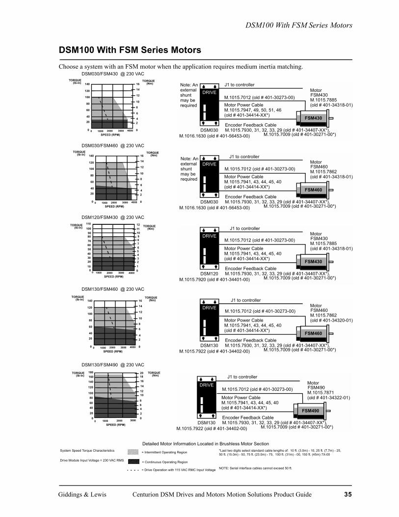
DSM100 With FSM Series Motors
DSM100 With FSM Series MotorsChoose a system with an FSM motor when the application requires medium inertia matching.
DSM030/FSM430 @ 230 VAC
DSM030/FSM460 @ 230 VAC
DSM120/FSM430 @ 230 VAC
DSM130/FSM460 @ 230 VAC
DSM130/FSM490 @ 230 VAC
Detailed Motor Information Located in Brushless Motor SectionSystem Speed Torque Characteristics = Intermittent Operating Region *Last two digits select standard cable lengths of: 10 ft. (3.0m) - 10, 25 ft. (7.7m) - 25,
50 ft. (15.0m) - 50, 75 ft. (23.0m) - 75, 100 ft. (31m) - 00, 150 ft. (45m) 7X-00
Drive Module Input Voltage = 230 VAC RMS = Continuous Operating Region
= Drive Operation with 115 VAC RMC Input Voltage NOTE: Serial interface cables cannot exceed 50 ft.
TORQUE(lb-in) TORQUE
(Nm)
SPEED (RPM)0 1000 2000 3000 4000 0
24
6
8
120
0
40
20
80
60
100
140
10
14
12
16
DRIVE
Encoder Feedback CableM.1015.7930, 31, 32, 33, 29 (old # 401-34407-XX*),
J1 to controller
Motor Power CableM.1015.7947, 49, 50, 51, 46
DSM030
(old # 401-34414-XX*)
M.1015.7885(old # 401-34318-01)
FSM430Motor
M.1016.1630 (old # 401-56453-00) M.1015.7009 (old # 401-30271-00*)
FSM430
Note: Anexternalshuntmay berequired
M.1015.7012 (old # 401-30273-00)
TORQUE(lb-in) TORQUE
(Nm)
SPEED (RPM)0 1000 2000 3000 4000 0
24
6
8
120
0
40
20
80
60
100
140
10
14
12
16
DRIVE
Encoder Feedback CableM.1015.7930, 31, 32, 33, 29 (old # 401-34407-XX*),
J1 to controller
Motor Power CableM.1015.7941, 43, 44, 45, 40
DSM030
(old # 401-34414-XX*)
M.1015.7862(old # 401-34318-01)
FSM460Motor
M.1016.1630 (old # 401-56453-00) M.1015.7009 (old # 401-30271-00*)
FSM460
Note: Anexternalshuntmay berequired
M.1015.7012 (old # 401-30273-00)
00 1000 3000 4000
TORQUE(lb-in) TORQUE
(Nm)
0
SPEED (RPM)
30
5060
1020
40
708090
100110
123456789
101112
2000
DRIVE
Encoder Feedback CableM.1015.7930, 31, 32, 33, 29 (old # 401-34407-XX*),
J1 to controller
Motor Power CableM.1015.7941, 43, 44, 45, 40
DSM120
(old # 401-34414-XX*)
M.1015.7885(old # 401-34318-01)
FSM430Motor
M.1015.7920 (old # 401-34401-00) M.1015.7009 (old # 401-30271-00*)
FSM430
M.1015.7012 (old # 401-30273-00)
TORQUE(lb-in) TORQUE
(Nm)
SPEED (RPM)0 1000 2000 3000 4000 0
24
6
8
120
0
40
20
80
60
100
140
10
14
12
16
DRIVE
Encoder Feedback CableM.1015.7930, 31, 32, 33, 29 (old # 401-34407-XX*),
J1 to controller
Motor Power CableM.1015.7941, 43, 44, 45, 40
DSM130
(old # 401-34414-XX*)
M.1015.7862(old # 401-34320-01)
FSM460Motor
M.1015.7922 (old # 401-34402-00) M.1015.7009 (old # 401-30271-00*)
FSM460
M.1015.7012 (old # 401-30273-00)
140
120
0
40
20
TORQUE(lb-in)
TORQUE(Nm)
0 1000 2000 3000SPEED (RPM)
80
160
60
100
02
180
468
1214161820
10
DRIVE
Encoder Feedback CableM.1015.7930, 31, 32, 33, 29 (old # 401-34407-XX*),
J1 to controller
Motor Power CableM.1015.7941, 43, 44, 45, 40
DSM130
(old # 401-34414-XX*)
M.1015.7871(old # 401-34322-01)
FSM490Motor
M.1015.7922 (old # 401-34402-00) M.1015.7009 (old # 401-30271-00*)
FSM490
M.1015.7012 (old # 401-30273-00)
Giddings & Lewis Centurion DSM Drives and Motors Motion Solutions Product Guide 35

DSM100 With FSM Series Motors
DSM175/FSM490 @ 230 VAC
DSM175/FSM610 @ 230 VAC
DSM175/FSM620 @ 230 VAC
DSM175/FSM630 @ 230 VAC
DSM1150/FSM620 @ 230 VAC
Detailed Motor Information Located in Brushless Motor SectionSystem Speed Torque Characteristics = Intermittent Operating Region *Last two digits select standard cable lengths of: 10 ft. (3.0m) - 10, 25 ft. (7.7m) - 25,
50 ft. (15.0m) - 50, 75 ft. (23.0m) - 75, 100 ft. (31m) - 00, 150 ft. (45m) 7X-00
Drive Module Input Voltage = 230 VAC RMS = Continuous Operating Region
= Drive Operation with 115 VAC RMC Input Voltage NOTE: Serial interface cables cannot exceed 50 ft.
180
0
60
30
TORQUE(lb-in)
TORQUE(Nm)
0 1000 2000 3000SPEED (RPM)
120
90
150
03
6
12
9
15
18
21210
DRIVE
Encoder Feedback CableM.1015.7930, 31, 32, 33, 29 (old # 401-34407-XX*),
J1 to controller
Motor Power CableM.1015.7941, 43, 44, 45, 40
DSM175
(old # 401-34414-XX*)
M.1015.7871(old # 401-34322-01)
FSM460Motor
M.1015.7924 (old # 401-34403-00) M.1015.7009 (old # 401-30271-00*)
FSM490
M.1015.7012 (old # 401-30273-00)
240
0
80
40
TORQUE(lb-in)
TORQUE(Nm)
0 1000 2000 3000SPEED (RPM)
160120
200
05
10
20
15
25
30
35280
320360 40
300
0
10050
TORQUE(lb-in)
TORQUE(Nm)
0 1000 2000 3000SPEED (RPM)
200
150
250
0
510
20
15
253035
350400
4045
DRIVE
Encoder Feedback CableM.1015.7930, 31, 32, 33, 29 (old # 401-34407-XX*),
J1 to controller
Motor Power CableM.1015.7953, 55, 56, 57, 52
DSM175
(old # 401-34415-XX*)
M.1015.7885(old # 401-34326-01)
FSM620Motor
M.1015.7924 (old # 401-34403-00) M.1015.7009 (old # 401-30271-00*)
FSM620
M.1015.7013 (old # 401-30274-00)
300
0
100
50
TORQUE(lb-in)
TORQUE(Nm)
0 1000 2000 3000SPEED (RPM)
200150
250
05
10
2015
253035
350
400450
404550
DRIVE
Encoder Feedback CableM.1015.7930, 31, 32, 33, 29 (old # 401-34407-XX*),
J1 to controller
Motor Power CableM.1015.7953, 55, 56, 57, 52
DSM175
(old # 401-34415-XX*)
M.1015.7891(old # 401-34328-01)
FSM630Motor
M.1015.7924 (old # 401-34403-00) M.1015.7009 (old # 401-30271-00*)
FSM630
M.1015.7013 (old # 401-30274-00)
300
0
10050
TORQUE(lb-in)
TORQUE(Nm)
0 1000 2000 3000SPEED (RPM)
200
150
250
0
5.711.3
22.6
17.0
28.3
33.939.6350
400 45.2
DRIVE
Encoder Feedback CableM.1015.7930, 31, 32, 33, 29 (old # 401-34407-XX*),
J1 to controller
Motor Power CableM.1015.7953, 55, 56, 57, 52
DSM1150
(old # 401-34415-XX*)
M.1015.7885(old # 401-34326-01)
FSM620Motor
M.1015.7926 (old # 401-34404-00) M.1015.7009 (old # 401-30271-00*)
FSM620
M.1015.7013 (old # 401-30274-00)
DRIVE
Encoder Feedback CableM.1015.7930, 31, 32, 33, 29 (old # 401-34407-XX*),
J1 to controller
Motor Power CableM.1015.7953, 55, 56, 57, 52
DSM175
(old # 401-34415-XX*)
M.1015.7880(old # 401-34324-01)
FSM610Motor
M.1015.7924 (old # 401-34403-00) M.1015.7009 (old # 401-30271-00*)
FSM610
M.1015.7013 (old # 401-30274-00)
36 Centurion DSM Drives and Motors Motion Solutions Product Guide Giddings & Lewis

DSM100 With FSM Series Motors
DSM1150/FSM630 @ 230 VAC
Detailed Motor Information Located in Brushless Motor SectionSystem Speed Torque Characteristics = Intermittent Operating Region *Last two digits select standard cable lengths of: 10 ft. (3.0m) - 10, 25 ft. (7.7m) - 25,
50 ft. (15.0m) - 50, 75 ft. (23.0m) - 75, 100 ft. (31m) - 00, 150 ft. (45m) 7X-00
Drive Module Input Voltage = 230 VAC RMS = Continuous Operating Region
= Drive Operation with 115 VAC RMC Input Voltage NOTE: Serial interface cables cannot exceed 50 ft.
300
0
100
TORQUE(lb-in)
TORQUE(Nm)
0 1000 2000 3000SPEED (RPM)
200
0
11.3
22.6
33.9
56.5
400 45.2
500
600 67.8
DRIVE
Encoder Feedback CableM.1015.7930, 31, 32, 33, 29 (old # 401-34407-XX*),
J1 to controller
Motor Power CableM.1015.7953, 55, 56, 57, 52
DSM1150
(old # 401-34415-XX*)
M.1015.7891(old # 401-34328-01)
FSM630Motor
M.1015.7926 (old # 401-34404-00) M.1015.7009 (old # 401-30271-00*)
FSM630
M.1015.7013 (old # 401-30274-00)
Giddings & Lewis Centurion DSM Drives and Motors Motion Solutions Product Guide 37
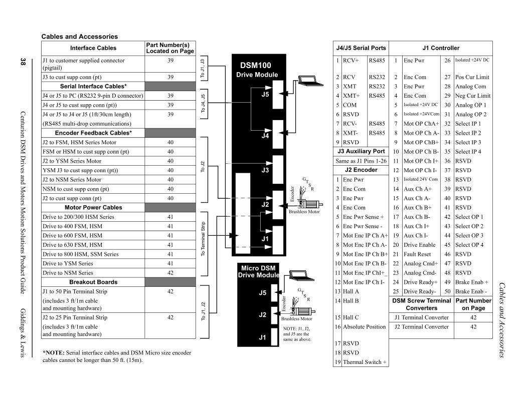
Cables and Accessories
rts J1 Controller
85 1 Enc Pwr 26 Isolated +24V DC
32 2 Enc Com 27 Pos Cur Limit32 3 Enc Pwr 28 Analog Com85 4 Enc Com 29 Neg Cur Limit
5 Isolated +24V DC 30 Analog OP 16 Isolated +24VCom 31 Analog OP 2
85 7 Mot OP ChA+ 32 Select IP 185 8 Mot OP Ch A- 33 Select IP 2
9 Mot OP ChB+ 34 Select IP 3rt 10 Mot OP Ch B- 35 Select IP 4
-26 11 Mot OP Ch I+ 36 RSVD12 Mot OP Ch I- 37 RSVD13 Isolated 24V Com 38 RSVD14 Aux Ch A+ 39 RSVD15 Aux Ch A- 40 RSVD16 Aux Ch B+ 41 RSVD
+ 17 Aux Ch B- 42 Select OP 1 - 18 Aux Ch I+ 43 Select OP 2 A+ 19 Aux Ch I- 44 Select OP 3 A- 20 Drive Enable 45 Select OP 4 B+ 21 Fault Reset 46 RSVD B- 22 Analog Cmd+ 47 RSVDI+_ 23 Analog Cmd- 48 RSVD I- 24 Drive Ready+ 49 Brake Enab +
25 Drive Ready- 50 Brake Enab -DSM Screw Terminal
ConvertersPart Number
on PageJ1 Terminal Converter 42
ion J2 Terminal Converter 42
h +
38C
enturion DSM
Drives and M
otors Motion Solutions Product G
uideG
iddings & Lew
is
Cables and AccessoriesInterface Cables Part Number(s)
Located on Page J4/J5 Serial Po
J1 to customer supplied connector(pigtail)
39 1 RCV+ RS4
J3 to cust supp conn (pt) 39 2 RCV RS2Serial Interface Cables* 3 XMT RS2
J4 or J5 to PC (RS232 9-pin D connector) 39 4 XMT+ RS4J4 or J5 to cust supp conn (pt)) 39 5 COMJ4 or J5 to J4 or J5 (1ft/30cm length) 39 6 RSVD(RS485 multi-drop communications) 7 RCV- RS4
Encoder Feedback Cables* 8 XMT- RS4J2 to FSM, HSM Series Motor 40 9 RSVDFSM or HSM to cust supp conn (pt) 40 J3 Auxiliary PoJ2 to YSM Series Motor 40 Same as J1 Pins 1YSM J3 to cust supp conn (pt)) 40 J2 EncoderJ2 to NSM Series Motor 40 1 Enc PwrNSM to cust supp conn (pt) 40 2 Enc ComJ2 to cust supp conn (pt) 40 3 Enc Pwr
Motor Power Cables 4 Enc ComDrive to 200/300 HSM Series 41 5 Enc Pwr SenseDrive to 400 FSM, HSM 41 6 Enc Pwr SenseDrive to 600 FSM, HSM 41 7 Mot Enc IP ChDrive to 630 FSM, HSM 41 8 Mot Enc IP ChDrive to 800 HSM, SSM Series 41 9 Mot Enc IP ChDrive to YSM Series 41 10 Mot Enc IP ChDrive to NSM Series 42 11 Mot Enc IP Ch
Breakout Boards 12 Mot Enc IP ChJ1 to 50 Pin Terminal Strip 42 13 Hall A(includes 3 ft/1m cableand mounting hardware)
14 Hall B
J2 to 25 Pin Terminal Strip 42 15 Hall C(includes 3 ft/1m cableand mounting hardware)
16 Absolute Posit
17 RSVD*NOTE: Serial interface cables and DSM Micro size encoder cables cannot be longer than 50 ft. (15m).
18 RSVD19 Thermal Switc
DSM100 Drive Module
J5
J4
J3
J2
J1
Micro DSM Drive Module
J5
J2
J1
To J
1, J
2To
Ter
min
al S
trip
To J
2To
J4,
J5
NOTE: J1, J2, and J5 are the same as above.
GTS
R
Brushless Motor
Enco
der
GTS
R
Brushless Motor
Enco
der
To J
1, J
3

Cables and Accessories
DSM 100 Cables and Accessories - Part NumbersNote: Refer to the Giddings & Lewis Price List for a complete list of part numbers for thevarious cable lengths including straight and right angle connectors.
Interface Cables
Description Length Part Number
J1 to customer supplied connector (pigtail) 10’ M.1015.7937 (old # 401-34411-10)
25’ M.1015.7938 (old 3 401-34411-25)
50’ M.1300.3513 (old #401-34411-50 )
75’ M.1015.7939 (old # 401-34411-75 )
J3 to customer supplied connector (pigtail) 10’ M.1015.7936 (old # 401-34410-10)
25’ M.1300.3510 (old # 401-34410-25)
50’ M.1300.3511 (old # 401-34410-50)
75 M.1300.3512 (old # 401-34410-75)
Serial Interface Cables
Description Length Part Number
J4 or J5 to PC (RS232 9-pin D connector) 10’ M.1016.9514 (old # 502-04020-10)
25’ M.1016.9515 (old # 502-04020-25)
50’ M.1016.9516 (old # 502-04020-50)
J4 or J5 to customer supplied connector(pigtail)
10’ M.1015.7973 (old # 401-34423-10)
25’ M.1300.3515 (old # 401-34423-25)
50’ M.1300.3516 (old # 401-34423-50)
J4 or J5 to J4 or J5 (1ft/30cm length)(for RS485 Multi-Drop Communications)
N/A M.1016.9517 (old # 502-04021-01)
Giddings & Lewis Centurion DSM Drives and Motors Motion Solutions Product Guide 39

Cables and Accessories
Encoder Feedback Cables
Description Length Part NumberJ2 to FSM or HSM Series Motor 10’ M.1015.7930 (old # 401-34407-10)
25’ M.1015.7931 (old # 401-34407-250
50’ M.1015.7932 (old # 401-34407-50)
75’ M.1015.7933 (old # 401-34407-75)
100’ M.1015.7929 (old # 401-34407-00)
150’ M.1015.7009 (old # 401-30271-00)
FSM or HSM to customer supplied connector (pigtail)
10’ M.1015.7980 (old # 401-34425-10)
25’ M.1015.7981 (old # 401-34425-25)
50’ M.1015.7982 (old # 401-34425-50)
75’ M.1015.7983 (old # 401-34425-75)
100’ M.1015.7979 (old # 401-34425-00)
150’ M.1015.7011 (old # 401-30272-00)
J2 to YSM Series Motor 10’ M.1015.6941 (old # 401-30233-10)
25’ M.1015.6942 (old # 401-30233-25)
50’ M.1015.6943 (old # 401-30233-50)
75’ M.1015.6944 (old # 401-30233-75)
100’ M.1015.6940 (old # 401-30233-00)
YSM J3 to customer supplied connector(pigtail)
10’ M.1015.6986 (old # 401-30253-10)
25’ M.1015.6987 (old # 401-30253-25)
50’ M.1015.6988 (old # 401-30253-50)
75’ M.1015.6989 (old # 401-30253-75)
100’ M.1300.3508 (old # 401-30253-00)
J2 to NSM Series Motor (straight) 10’ M1015.6931 (old # 401-30231-10)
25’ M1015.6932 (old # 401-30231-25)
50’ M.1015.6933 (old # 401-30231-50)
75’ M.1015.6934 (old # 401-30231-75)
100’ M.1015.6930 (old # 401-30231-00)
NSM Series Motor to customer suppliedconnector (pigtail)
10’ M.1015.6931 (old # 401-30252-10)
25’ M1015.6983 (old # 401-30252-25)
50’ M.1015.6984 (old # 401-30252-50)
75’ M.1015.6985 (old # 401-30252-75)
100’ M.1015.6981 (old # 401-30252-00)
J2 to customer supplied connector (pigtail) 10’ M.1015.7975 (old # 401-34424-10)
25’ M1015.7976 (old # 401-34424-25)
50’ M.1015.7977 (old # 401-34424-50)
75’ M.1015.7978 (old # 401-34424-75)
100’ M.1015.7974 (old # 401-34424-00)
40 Centurion DSM Drives and Motors Motion Solutions Product Guide Giddings & Lewis
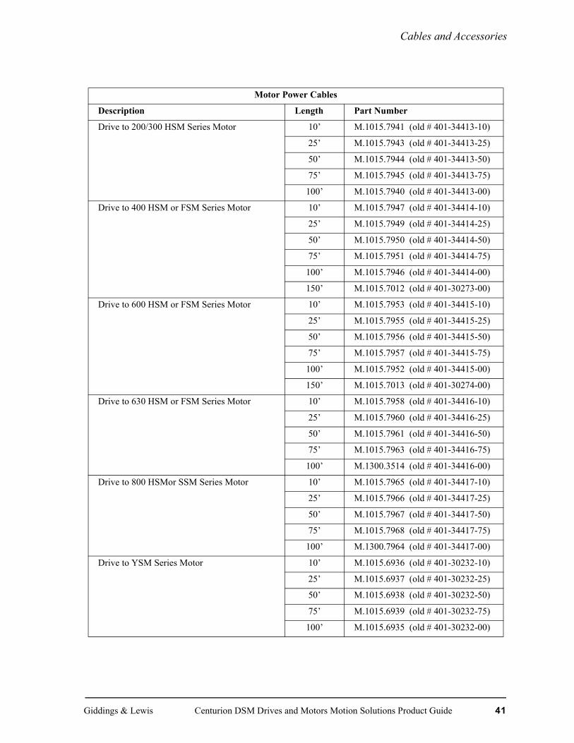
Cables and Accessories
Motor Power Cables
Description Length Part Number
Drive to 200/300 HSM Series Motor 10’ M.1015.7941 (old # 401-34413-10)
25’ M.1015.7943 (old # 401-34413-25)
50’ M.1015.7944 (old # 401-34413-50)
75’ M.1015.7945 (old # 401-34413-75)
100’ M.1015.7940 (old # 401-34413-00)
Drive to 400 HSM or FSM Series Motor 10’ M.1015.7947 (old # 401-34414-10)
25’ M.1015.7949 (old # 401-34414-25)
50’ M.1015.7950 (old # 401-34414-50)
75’ M.1015.7951 (old # 401-34414-75)
100’ M.1015.7946 (old # 401-34414-00)
150’ M.1015.7012 (old # 401-30273-00)
Drive to 600 HSM or FSM Series Motor 10’ M.1015.7953 (old # 401-34415-10)
25’ M.1015.7955 (old # 401-34415-25)
50’ M.1015.7956 (old # 401-34415-50)
75’ M.1015.7957 (old # 401-34415-75)
100’ M.1015.7952 (old # 401-34415-00)
150’ M.1015.7013 (old # 401-30274-00)
Drive to 630 HSM or FSM Series Motor 10’ M.1015.7958 (old # 401-34416-10)
25’ M.1015.7960 (old # 401-34416-25)
50’ M.1015.7961 (old # 401-34416-50)
75’ M.1015.7963 (old # 401-34416-75)
100’ M.1300.3514 (old # 401-34416-00)
Drive to 800 HSMor SSM Series Motor 10’ M.1015.7965 (old # 401-34417-10)
25’ M.1015.7966 (old # 401-34417-25)
50’ M.1015.7967 (old # 401-34417-50)
75’ M.1015.7968 (old # 401-34417-75)
100’ M.1300.7964 (old # 401-34417-00)
Drive to YSM Series Motor 10’ M.1015.6936 (old # 401-30232-10)
25’ M.1015.6937 (old # 401-30232-25)
50’ M.1015.6938 (old # 401-30232-50)
75’ M.1015.6939 (old # 401-30232-75)
100’ M.1015.6935 (old # 401-30232-00)
Giddings & Lewis Centurion DSM Drives and Motors Motion Solutions Product Guide 41

Cables and Accessories
Drive to NSM Series Motor 10’ M.1015.6926 (old # 401-30230-10)
25’ M.1015.6927 (old # 401-30230-25)
50’ M.1015.6928 (old # 401-30230-50)
75’ M.1015.6929 (old # 401-30230-75)
100’ M.1015.6925 (old # 401-30230-00)
Breakout Boards
Description Part Number
J1 to 50 Pin Terminal Strip(includes 3ft/1m cable and mountinghardware)
M.1015.7935 (old # 401-34409-00)
J2 to 25 Pin Terminal Strip(includes 3ft/1m cable and mountinghardware)
M.1015.7934 (old # 401-34408-00)
DSM Screw Terminal Converters
Description Part Number
J1 Terminal Converter M.1016.9545 (old # 502-04051-00)
J2 Terminal Convertor M.1016.9581 (old # 502-04076-00)
42 Centurion DSM Drives and Motors Motion Solutions Product Guide Giddings & Lewis

DSM Options and Accessories
DSM Options and Accessories
Touch Pad
M.1015.7928 (old # 401-34405-00)
Touch Pad
2.00
2.25
1.09
Touch Pad Dimensions
Giddings & Lewis Centurion DSM Drives and Motors Motion Solutions Product Guide 43

DSM Options and Accessories
AC Line Filters
AC Line Filters Specifications
AC Line Filters (Required for EMC Compliance)
Current Model Part NumberI = 6A 1φ DSM007 M.1015.6922 (old # 401-30222-00)I = 10A 1φ DSM015, DSM110 M.1015.6917 (old # 401-30216-00)I = 23A 1φ DSM030, DSM120 M.1015.6918 (old # 401-30217-00)I = 36A 1φ DSM130, DSM175 1φ M.1015.7969 (old # 401-34418-00)I = 36A 3φ DSM130, DSM175 M.1015.7970 (old # 401-34419-00)I = 50A 1φ For multiple drives on one filter.
Combined drive input currents may not exceed filter current rating.
M.1015.7971 (old # 401-34420-00)
I = 70A 3φ For multiple DSM175 drives on one filter. Combined drive input currents may not exceed filter current
M.1015.7972 (old # 401-34421-00)
44 Centurion DSM Drives and Motors Motion Solutions Product Guide Giddings & Lewis

DSM Options and Accessories
AC Line Filters Dimensions
M.1015.6922 (old # 401-30222-00) M.1015.6917 (old # 401-30216-00)
M.1015.6918 (old # 401-30217-00)M.1015.7971 (old # 401-34420-00)
M.1015.7970 (old # 401-34419-00) M.1015.7969 (old # 401-34418-00)
9 (2) 152 (2)
LIN
EE
L N
170 5 (4)
E L
’ N
’
LOAD
55 (2)
18 (2)
92
25
10 (2)
9 (2) 152 (2)
6 (4)
LIN
EE
L N
192 (2)
104 (2)
20 (2)
145
16 (2)
9 (2) 152 (2)
5(4)
11(2)214
LOA
DE
L’N
’
40
11 (2)192 (2)
7 (4)
20 (2)
LO
AD
E
L’N
’
LIN
E
LN
E
192 (2)11(2)
164 (2)
20 (2)
5 (4)
204
47
19 (4)
11 (2)192 (2)
7 (4)
101.00 (2)
(L) (L’)
(N) (N’)
20.0080.00 (2)
22.00 (4)
104.00 (2) M6 (4)
(E)
174.00
12.00
R3.00
12.00
86.00
60.00 (2)
55.00
20.00120.00
M6X12
LOAD
128.00 (2)
(L1)
(E) LOAD
120.00 (2)
110.00 (3)
(E)
230.00
12.00
R3.00
12.00
25.00 (2)
55.00
14.00
147.00
(L2)
(L3)
(L1’)
(L2’)(L3’)
LINE
22.00(6)
25.00 (2)25.00
147.00
101.00 (2)
(L1) (L’)
(N) (N’)
20.0080.00 (2)
22.00 (4)
104.00 (2) M6 (4)
(E)
174.00
12.00
R3.00
12.00
86.00
60.00 (2)
55.00
20.00120.00
M6X12
LOAD
Giddings & Lewis Centurion DSM Drives and Motors Motion Solutions Product Guide 45
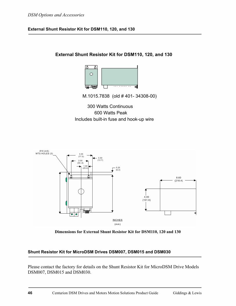
DSM Options and Accessories
External Shunt Resistor Kit for DSM110, 120, and 130
Shunt Resistor Kit for MicroDSM Drives DSM007, DSM015 and DSM030
Please contact the factory for details on the Shunt Resistor Kit for MicroDSM Drive Models DSM007, DSM015 and DSM030.
External Shunt Resistor Kit for DSM110, 120, and 130
M.1015.7838 (old # 401- 34308-00)
300 Watts Continuous600 Watts Peak
Includes built-in fuse and hook-up wire
8.60(218.4)
4.00(101.6)
3.05(77.5)
2.00(50..8)
1.00(25.4)
0.50(12.7)
0.25(6.3)
#10 (m5)MTS HOLES (3)
INCHES
(mm)
Dimensions for External Shunt Resistor Kit for DSM110, 120 and 130
46 Centurion DSM Drives and Motors Motion Solutions Product Guide Giddings & Lewis
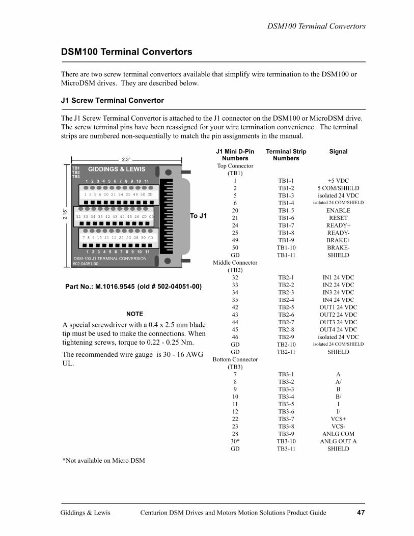
DSM100 Terminal Convertors
DSM100 Terminal Convertors
There are two screw terminal convertors available that simplify wire termination to the DSM100 or MicroDSM drives. They are described below.
J1 Screw Terminal Convertor
The J1 Screw Terminal Convertor is attached to the J1 connector on the DSM100 or MicroDSM drive. The screw terminal pins have been reassigned for your wire termination convenience. The terminal strips are numbered non-sequentially to match the pin assignments in the manual.
NOTE
A special screwdriver with a 0.4 x 2.5 mm blade tip must be used to make the connections. When tightening screws, torque to 0.22 - 0.25 Nm.
The recommended wire gauge is 30 - 16 AWG UL.
*Not available on Micro DSM
J1 Mini D-Pin Numbers
Terminal Strip Numbers
Signal
Top Connector (TB1)
1 TB1-1 +5 VDC2 TB1-2 5 COM/SHIELD5 TB1-3 isolated 24 VDC6 TB1-4 isolated 24 COM/SHIELD
20 TB1-5 ENABLE21 TB1-6 RESET24 TB1-7 READY+25 TB1-8 READY-49 TB1-9 BRAKE+50 TB1-10 BRAKE-GD TB1-11 SHIELD
Middle Connector (TB2)
32 TB2-1 IN1 24 VDC33 TB2-2 IN2 24 VDC34 TB2-3 IN3 24 VDC35 TB2-4 IN4 24 VDC42 TB2-5 OUT1 24 VDC43 TB2-6 OUT2 24 VDC44 TB2-7 OUT3 24 VDC45 TB2-8 OUT4 24 VDC46 TB2-9 isolated 24 VDCGD TB2-10 isolated 24 COM/SHIELD
GD TB2-11 SHIELDBottom Connector
(TB3)7 TB3-1 A8 TB3-2 A/9 TB3-3 B
10 TB3-4 B/11 TB3-5 I12 TB3-6 I/22 TB3-7 VCS+23 TB3-8 VCS-28 TB3-9 ANLG COM30* TB3-10 ANLG OUT AGD TB3-11 SHIELD
1 2 5 6 20 21 24 25 49 50 GD
502-04051-00
GIDDINGS & LEWISTB1TB2TB3
1 2 3 4 5 6 7 8 9 10 11
1 2 3 4 5 6 7 8 9 10 11 DSM-100 J1 TERMINAL CONVERSION
7 8 9 10 11 12 22 23 28 30 GD
32 33 34 35 42 43 44 45 26 GD GD To J1
2.3”
2.15
”
Part No.: M.1016.9545 (old # 502-04051-00)
Giddings & Lewis Centurion DSM Drives and Motors Motion Solutions Product Guide 47

DSM100 Terminal Convertors
J2 Screw Terminal Convertor
The J2 Screw Terminal Convertor is attached to the J2 connector on the DSM100 or MicroDSM drive. The screw terminal pins have been reassigned for your wire termination convenience. The terminal strips are numbered non-sequentially to match the pin assignments in the manual.
NOTE
A special screwdriver with a 0.4 x 2.5 mm blade tip must be used to make the connections. When tightening screws, torque to 0.22 - 0.25 Nm.
The recommended wire gauge is 30 - 16 AWG UL.
J2 Mini D-Pin Numbers
Terminal Strip Numbers
Signal
Top Connector (TB1)
1 TB1-1 +5 VDC2 TB1-2 5 COM3 TB1-3 +5 VDC4 TB1-4 5 COM5 TB1-5 5 VDC SENSE+6 TB1-6 5 VDC SENSE-
GD TB1-7 SHIELD19 TB1-8 TEMP+20 TB1-9 TEMP-GD TB1-10 SHIELDGD TB1-11 SHIELD
Bottom Connector (TB2)
7 TB2-1 A8 TB2-2 A/9 TB2-3 B
10 TB2-4 B/GD TB2-5 SHIELD11 TB2-6 I12 TB2-7 I/13 TB2-8 U14 TB2-9 V15 TB2-10 W16 TB2-11 ABS
502-04076-00GIDDINGS & LEWISTB1
TB21 2 3 4 5 6 7 8 9 10 11
1 2 3 4 5 6 7 8 9 10 11 DSM-100 J2 TERMINAL CONVERSION
7 8 9 10 GD 11 12 13 14 15 16
1 2 3 4 5 6 GD 19 20 GD GD
To J2
2.3”
1.4”
Part No.: M.1016.9581 (old # 502-04076-00)
48 Centurion DSM Drives and Motors Motion Solutions Product Guide Giddings & Lewis

SERCOS Fiber Optic Cables
SERCOS Fiber Optic Cables
FIGURE 1. Heavy Duty SERCOS Fiber Optic Cable
Description Length Part NumberStandard Cable 1’ M.1016.9743 (old # 502-04170-01)
3’ M.1016.9744 (old # 502-04170-03)
5’ M.1016.9745 (old # 502-04170-05)
10’ M.1016.9747 (old # 502-04170-10)
15’ M.1016.9749 (old # 502-04170-15)
25’ M.1016.9753 (old # 502-04170-25)
Heavy Duty Cable .05 Meters (1.5’) M.0106.9758 (old # 502-04171-01)
1 Meter (3.3’) M.0106.9760 (old # 502-04171-03)
2 Meters (6.6’) M.0106.9763 (old # 502-04171-06)
3 Meters (9.9’) M.0106.9767 (old # 502-04171-10)
5 Meters (16.5’) M.0106.9773 (old # 502-04171-16)
10 Meters (32.5’) M.0106.9784 (old # 502-04171-32)
Giddings & Lewis Centurion DSM Drives and Motors Motion Solutions Product Guide 49
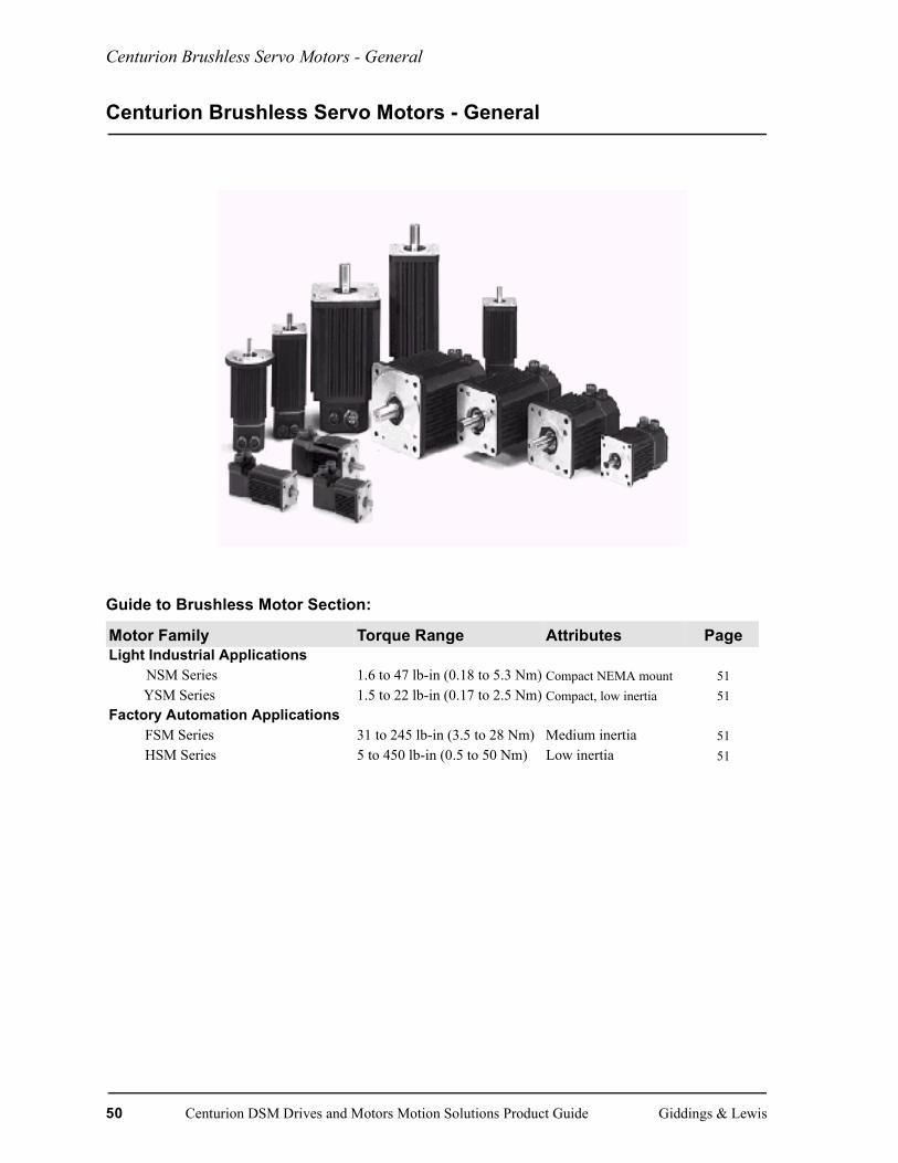
Centurion Brushless Servo Motors - General
Centurion Brushless Servo Motors - General
Guide to Brushless Motor Section:
Motor Family Torque Range Attributes PageLight Industrial Applications
NSM Series 1.6 to 47 lb-in (0.18 to 5.3 Nm) Compact NEMA mount 51YSM Series 1.5 to 22 lb-in (0.17 to 2.5 Nm) Compact, low inertia 51
Factory Automation ApplicationsFSM Series 31 to 245 lb-in (3.5 to 28 Nm) Medium inertia 51HSM Series 5 to 450 lb-in (0.5 to 50 Nm) Low inertia 51
50 Centurion DSM Drives and Motors Motion Solutions Product Guide Giddings & Lewis

NSM Brushless Servo Motors
NSM Brushless Servo Motors
Typical Applications Standard Features• Semi-conductor manufacturing • Rugged industrial construction• Material handling • High torque to size ratio• Web processing • High energy ring magnet rotor• Robotics • Integral encoder• Packaging machinery • Provision for optional shaft seal
• NEMA 23, 34, 42, 56 style mounting frames
Giddings & Lewis Centurion DSM Drives and Motors Motion Solutions Product Guide 51

NSM
Brushless Servo Motors
52C
enturion DSM
Drives and M
otors Motion Solutions Product G
uideG
iddings & Lew
i s
NSM Series Motor And Performance Data
x 30 cm) aluminum heat sink. 5Motor windings
630 NSM5637 NSM5647
kg-m2 lb-in-s2 kg-m2 lb-in-s2 kg-m2
0.0009 0.01 0.0011 0.013 0.0015kg lb kg lb kg9.1 24.2 11.0 28.7 13.0Nm lb-in Nm lb-in Nm
0.078 0.875 0.1 0.938 0.11
Nm/A lb-in/A Nm/A lb-in/A Nm/A.38 4.4 .50 5.6 .63
0.42 4.8 0.54 6.2 0.70RPM 60 V/kRPM 78 V/kRPM
¾ 1.0 ¾ 1.23 ¾
H 5.2 mH 7.0 mH
/watt 0.76°C/watt 0.70°C/watt
030 DSM 030 DSM0300 4000 3000
Nm lb-in Nm lb-in Nm3.4 40.0 4.5 52.0 2.0Nm lb-in Nm lb-in Nm10.7 120 13.0 150 17.0
130 DSM 130 DSM 1300 4000 3000
Nm lb-in Nm lb-in Nm0.8 46.0 1.6 53.0 5.9Nm lb-in Nm lb-in Nm2.1 120 4.1 150 5.7
1Peak value of per phase sine wave amps 2Peak value of per phase square wave amps 3Peak value of sinusoidal phase to phase volt 4Motor mounted on .5” x 12” x 12” (1.2 x 30designed for 115V drive input voltage. .
Motor Model NSM2302 NSM2304 NSM3406 NSM3412 NSM4214 NSM4220 NSM5Mechanical Data
Rotor Moment lb-in-s2 kg-m2 lb-in-s2 kg-m2 lb-in-s2 kg-m2 lb-in-s2 kg-m2 lb-in-s2 kg-m2 lb-in-s2 kg-m2 lb-in-s2
of Inertia 0.00008 .000009 .00016 0.00002 0.0007 0.00008 0.0013 0.00015 0.0021 0.00024 0.0031 0.00035 0.008Motor lb kg lb kg lb kg lb kg lb kg lb kg lbNet Weight 2.3 1.0 3.4 1.5 5.7 2.6 7.6 3.5 10.4 4.7 13.0 8.9 20.0
lb-in Nm lb-in Nm lb-in Nm lb-in Nm lb-in Nm lb-in Nm lb-inFriction Torque 0.11 0.012 0.13 0.014 0.19 0.021 0.31 0.035 0.38 0.043 0.406 0.046 0.688Winding DataSine Wave KT Torque lb-in/A Nm/A lb-in/A Nm/A lb-in/A Nm/A lb-in/A Nm/A lb-in/A Nm/A lb-in/A Nm/A lb-in/AConstant @ 25°C(1) 0.73 .08 1.6 0.18 1.5 0.17 3.0 0.34 3.6 0.41 2.5 0.28 3.5Sq Wave KT TorqueConstant @ 25°C(2) 0.80 0.09 1.8 0.20 1.6 0.18 3.3 0.37 4.0 0.45 2.7 0.31 3.7KE Voltage Con-stant(3)
10 V/kRPM 24 V/kRPM 20 V/kRPM 40 V/kRPM 46 V/kRPM 33 V/kRPM 48 V/k
Winding ResistancePh to phase @ 25°C
3.18 ¾ 4.9 ¾ 2.2 ¾ 2.7 ¾ 2.8¾ 0.77 ¾ 0.89
Winding InductancePhase to phase
4.1 mH 8.1 mH 6.1 mH 8.6 mH 11.0 mH 2.9 mH 4.3 m
Thermal Resistance(4) 3.0°C/watt 2.2°C/watt 1.6°C/watt 1.2°C/watt 1.1°C/watt 0.83°C/watt 0.81°C
System Ratings(5)
DSM 007 DSM 007/015 DSM 015 DSM 015 DSM 015 DSM 030 DSMMax. Continuous Operation Speed RPM
6000 6000 6000 5500 4500 5000 400
Continuous Stall lb-in Nm lb-in Nm lb-in Nm lb-in Nm lb-in Nm lb-in Nm lb-inTorque 1.6 0.2 3.5/4.4 0.4/0.5 6.8 0.8 13.8 1.6 15.5 2.0 22.0 2.5 30.0Peak lb-in Nm lb-in Nm lb-in Nm lb-in Nm lb-in Nm lb-in Nm lb-inTorque 4.6 0.5 10/13 1.1/1.4 18.5 2.1 36.0 4.1 45.0 5.7 63.0 7.1 95.0
DSM 110 DSM 110 DSM120 DSM 120 DSM 120 DSM 130 DSMMax. Continuous Operation Speed RPM
6000 6000 6000 5500 5000 5000 400
Continuous Stall lb-in Nm lb-in Nm lb-in Nm lb-in Nm lb-in Nm lb-in Nm lb-inTorque 1.7 0.2 4.4 0.5 6.8 0.8 13.8 1.6 18.0 2.0 26.0 0.4 34.0Peak lb-in Nm lb-in Nm lb-in Nm lb-in Nm lb-in Nm lb-in Nm lb-inTorque 4.7 0.5 13.0 1.4 18.5 2.1 36.0 4.1 50.0 5.7 63.0 1.4 95.0

NSM Brushless Servo Motors
Motors are capable of carrying an axial load in most applications. The following table pro-vides guidelines for 20,000 hour bearing life with a specified radial load applied to the center of the shaft. Please consult with Giddings & Lewis regarding loads, operating speeds and bearing life in your particular application to ensure the proper selection of motors.
STANDARD RADIAL LOAD FORCE RATINGS500 rpm 1000 rpm 2000 rpm 3000 rpm 4000 rpm 5000 rpm 6000 rpm
MOTOR lb (kg) lb (kg) lb (kg) lb (kg) lb (kg) lb (kg) lb (kg)NSM2302 17 (8) 16(7) 14 (6) 12 (6) 11 (5) 9 (4) 8 (3)NSM2304 19(9) 17 (8) 15 (7) 14 (6) 12 (5) 10 (5) 8 (4)NSM3406 103 (47) 82 (37) 65 (29) 56 (26) 51 (23) 48 (22) 45 (20)NSM3412 113 (51) 89 (40) 71 (32) 62 (28) 56 (26) 53 (24) 49 (22)NSM4214 137 (62) 109 (49) 86 (39) 76 (34) 68 (31) 64 (29)NSM4220 146 (66) 116 (52) 92 (41) 80 (36) 73 (33) 68 (31)NSM5630 188 (85) 149 (67) 118 (53) 103 (47) 94 (43)NSM5637 197 (89) 156 (71) 124 (56) 108 (49) 98 (45)NSM5647 203 (92) 161 (73) 128 (58) 112 (51)
NOTE: When motor shaft has no radial load, axial load rating = 100% of radial load rating above. When motor shaft has both a radial load and an axial load, axial load rating = 44% of radial load rating above.
Axial load force
Radial load force applied at center of shaft extension
P0010
Giddings & Lewis Centurion DSM Drives and Motors Motion Solutions Product Guide 53

NSM Brushless Servo Motors
NSM Motor Dimensions
1Tolerance is ±0.03/0.76, 2-0.005/0.05, 3-0.005/0.13 diameter, 4-0.006/0.15, 5-0.002/0.005 width -0.014/0.36 depth, 6-0.06/1.5, 7-0.001/0.025 diameter, 8-0.003/0.076NOTE: Motors are manufactured to inch dimensions. Millimeter dimensions are approximate conversions from inches.
Model AB AH AJ AK BB BE BF Lmm/in mm/in mm/in mm/in mm/in mm/in mm/in mm/in
NSM2302 69/2.75 21/.811 67/2.625 38/1.502 2/.09 7/.275 5/.205 118/4.634NSM2304 69/2.75 21/.811 67/2.625 38/1.502 2/.09 7/.275 5/.205 156/6.134NSM3406 64/2.48 30/1.191 98/3.875 73/2.8754 3/.12 8/.315 6/.220 147/5.67NSM3412 64/2.48 30/1.191 98/3.875 73/2.8754 3/.12 8/.315 6/.220 173/6.67NSM4214 63/2.45 35/1.381 126/4.95 56/2.1877 3/.12 10/.394 7/.280 174/6.845NSM4220 63/2.45 35/1.381 126/4.95 56/2.1877 3/.12 10/.394 7/.280 200/7.845NSM5630 76/2.96 50/1.971 149/5.875 114/4.508 3/.12 12/.472 9.5/.375 in UNC 199/7.825NSM5637 76/2.96 50/1.971 149/5.875 114/4.508 3/.12 12/.472 9.5/.375 in UNC 225/8.825NSM5647 76/2.96 50/1.971 149/5.875 114/4.508 3/.12 12/.472 9.5/.375 in UNC 250/9.825
Model LA LB P S U XDmm/in mm/in mm/in mm/in mm/in mm/in
NSM2302 62/2.43 106/4.05 58/2.27 N/A 6/.253 N/ANSM2304 100/3.93 141/5.55 58/2.27 N/A 6/.253 N/ANSM3406 124/4.87 N/A 89/3.48 3.2 x 3.2/0.125 x 0.1255 13/.53 20/.756
NSM3412 149/5.87 N/A 89/3.48 3.2 x 3.2/0.125 x 0.1255 13/.53 20/.756
NSM4214 152/5.99 N/A 102/4.0 4.8 x 4.8/0.1875 x 0.18755 16/.6253 25/0.946
NSM4220 178/6.99 N/A 102/4.0 4.8 x 4.8/0.1875 x 0.18755 16/.6253 25/0.946
NSM5630 178/7.0 N/A 127/5.0 4.8 x 4.8/0.1875 x 0.18755 19/.753 40/1.56
NSM5637 203/8.0 N/A 127/5.0 4.8 x 4.8/0.1875 x 0.18755 19/.753 40/1.56
NSM5647 229/9.0 N/A 127/5.0 4.8 x 4.8/0.1875 x 0.18755 19/.753 40/1.56
NSM24XX
NSM34XXNSM42XXNSM56XX
54 Centurion DSM Drives and Motors Motion Solutions Product Guide Giddings & Lewis
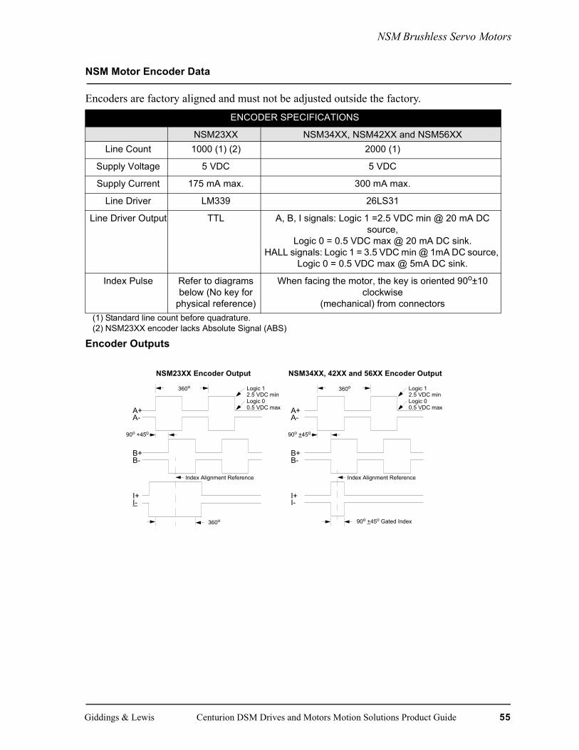
NSM Brushless Servo Motors
NSM Motor Encoder Data
Encoders are factory aligned and must not be adjusted outside the factory.
Encoder Outputs
ENCODER SPECIFICATIONS
NSM23XX NSM34XX, NSM42XX and NSM56XXLine Count 1000 (1) (2) 2000 (1)
Supply Voltage 5 VDC 5 VDC
Supply Current 175 mA max. 300 mA max.
Line Driver LM339 26LS31
Line Driver Output TTL A, B, I signals: Logic 1 =2.5 VDC min @ 20 mA DC source,
Logic 0 = 0.5 VDC max @ 20 mA DC sink.HALL signals: Logic 1 = 3.5 VDC min @ 1mA DC source,
Logic 0 = 0.5 VDC max @ 5mA DC sink.
Index Pulse Refer to diagrams below (No key for
physical reference)
When facing the motor, the key is oriented 90o±10clockwise
(mechanical) from connectors(1) Standard line count before quadrature. (2) NSM23XX encoder lacks Absolute Signal (ABS)
A+A-
B+B-
I+I-
Logic 1
Logic 0
90o +45o
Index Alignment Reference
360o
2.5 VDC min
0.5 VDC max A+A-
B+B-
I+I-
360o Logic 1
Logic 0
90o +45o
Index Alignment Reference
90o +45o Gated Index
2.5 VDC min
0.5 VDC max
NSM23XX Encoder Output NSM34XX, 42XX and 56XX Encoder Output
360o
Giddings & Lewis Centurion DSM Drives and Motors Motion Solutions Product Guide 55

NSM Brushless Servo Motors
Encoder Phase-to-Neutral and Phase-to-Phase Waveforms
NOTE: NSM34XX, NSM42XX and NSM56XX
NOTE: Hall and ABS signals are in electrical degrees.
For 4 pole commutation, 360° mechanical = 720° electrical.
56 Centurion DSM Drives and Motors Motion Solutions Product Guide Giddings & Lewis

NSM Brushless Servo Motors
NSM Motor Connector and Ordering Options
Ordering options include the following:• 24 VDC Brake (Consult factory for brake motor availability)• Encoder Line Count - 2,000 or 5,000 line• Motor Winding Voltage - 115 V or 230 V Drive Input Voltage• Continuous Torque Capability
Consult the factory for information on any of these items.
NOTE: Options are not available on all sizes.Optional configurations or encoder line counts have extended lead times and additional charges.
NOTE: 5000 line count encoder, motor top speed is limited to 3600 RPM due to frequency output limit of encoder-check drive system configuration data for any additional restrictions imposed by drive input.
NSM Connector Data
MOTOR MATING CONNECTORS
Description Part NumberMating Power M.1016.8056 (old # 401-34508-00)Mating Encoder M.1016.8057 (old # 401-34509-00)
NSM MOTOR SHAFT SEAL KITS
Description Part NumberNSM 2300 Series M.1300.0422 (old # 401-34510-00)NSM 3400 Series M.1015.8058 (old # 401-34511-00)NSM 4200 Series M.1015-8059 (old # 401-34512-00)NSM 5600 Series M.1300.0003 (old # 401-34513-00)
Giddings & Lewis Centurion DSM Drives and Motors Motion Solutions Product Guide 57

YSM Brushless Servo Motors
YSM Brushless Servo Motors
Typical Applications Standard Features• Robotics • 115V and 230V windings• Material handling • Popular metric mounting dimensions• Specialty machinery • Three frame sizes, 10 models• Medical and laboratory equipment • Torque range 1.5 - 22 lb-in (.17 - 2.5 Nm)• X-Y tables • Motor mounted optical encoder with differential • Light packaging machines line driver data (2,000 line) and commutation• Office machinery signals• Postal sorting • Low inertia rotor
• High energy neodymium magnets• 4500 rpm maximum• Optional internally mounted spring set, magnetic
release 24 VDC holding brake• IP-43 package
58 Centurion DSM Drives and Motors Motion Solutions Product Guide Giddings & Lewis
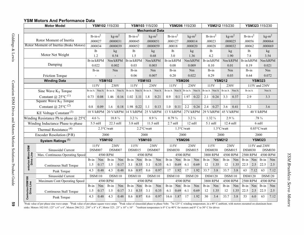
YSM Brushless Servo M
otorsmbient, with motors mounted on aluminum heat-
2 115/230 YSM323 115/230
kg-m2 lb-in-s2 kg-m2
.000025 .00056 .000064
.000032 .00062 .000069kg lb kg
1.90 7.8 3.54Nm/kRPM lb-in/kRPM Nm/kRPM
0.01 0.19 0.021Nm lb-in Nm0.03 0.64 0.072
M212 YSM323230V 115V and 230V
lb-in/A Nm/A lb-in/A Nm/A
3.3 0.37 2.9 3.3
3.6 0.41 3.2 3.645 V/kRPM 40 V/kRPM
2.9 ¾ .78 ¾12.4 mH 6 mH
C/watt 0.85°C/watt
000 2000M212 YSM323
230VDSM015
115V and 230VDSM030 DSM030
4500 RPM 2500 RPM 4500 RPMlb-in Nm lb-in Nm lb-in Nm12 1.35 22.5 2.5 22.5 2.5
33.7 3.8 63 7.12 63 7.12
DSM110 DSM120 DSM1204500 RPM 2500 RPM 4500 RPMlb-in Nm lb-in Nm lb-in Nm12 1.35 22.5 2.5 22.5 2.5
33.7 3.8 53 6.0 63 7.12
Giddings &
Lewis
Centurion D
SM D
rives and Motors M
otion Solutions Product Guide
59
YSM Motors And Performance Data
1Peak value of per phase sine wave amps 2Peak value of per phase square wave amps 3Peak value of sinusoidal phase to phase Volts 4At 125° C winding temperature, in a 40° C asinks: Motors 102/103:.125” x 6” x 6”, Motors 206/212: .250” x 8” x 8”, Motor 323: .25” x 10” x 10” 5Ambient temperature is 0° C to 40°C for motors and 0° C to 50° C for drives
Motor Model YSM102 115/230 YSM103 115/230 YSM206 115/230 YSM21Mechanical Data
lb-in-s2 kg-m2 lb-in-s2 kg-m2 lb-in-s2 kg-m2 lb-in-s2
Rotor Moment of Inertia .000027 .0000031 .000045 .0000051 .000127 .000014 .00023Rotor Moment of Inertia (Brake Motors) .000034 .0000039 .000052 .0000059 .00018 .000020 .00028
lb kg lb kg lb kg lbMotor Net Weight 1.2 0.54 1.5 0.68 3.0 1.36 4.2
lb-in/kRPM Nm/kRPM lb-in/kRPM Nm/kRPM lb-in/kRPM Nm/kRPM lb-in/kRPMDamping 0.022 0.002 0.03 0.003 0.08 0.009 0.10
lb-in Nm lb-in Nm lb-in Nm lb-inFriction Torque - - 0.06 0.007 0.20 0.022 0.29Winding Data YSM102 YSM103 YSM206 YS
115V 230V 115V 230V 115V 230V 115VSine Wave KT Torque lb-in/A Nm/A lb-in/A Nm/A lb-in/A Nm/A lb-in/A Nm/A lb-in/A Nm/A lb-in/A Nm/A lb-in/A Nm/A
Constant @ 25°C (1) 0.73 0.08 1.46 0.16 1.02 1.11 1.8 0.21 0.9 0.1 1.97 0.22 2.1 0.24Square Wave KT Torque
Constant @ 25°C (2) 0.8 0.09 1.6 0.18 1.98 0.22 1.1 0.13 1.0 0.11 2.2 0.24 2.4 0.27
KE Voltage Constant (3) 10 V/kRPM 20 V/kRPM 14 V/kRPM 25 V/kRPM 13 V/kRPM 27V/kRPM 29 V/kRPM
Winding Resistance Ph to phase @ 25°C 4.6 ¾ 18.8 ¾ 3.2 ¾ 8.9 ¾ 0.79 ¾ 3.2 ¾ 1.32 ¾Winding Inductance Phase to phase 5.5 mH 22.3 mH 3.8 mH 11.5 mH 2.7 mH 12 mH 5.1 mH
Thermal Resistance (4) 2.3°C/watt 2.2°C/watt 1.3°C/watt 1.3°
Encoder Resolution (P/R) 2000 2000 2000 2
System Ratings (5) YSM102 YSM103 YSM206 YS
Sinusoidal Current115V
DSM007230V
DSM007115V
DSM015230V
DSM007115V
DSM030230V
DSM015115V
DSM030Max. Continuous Operating Speed 4500 RPM 4500 RPM 4500 RPM 3800 RPM
lb-in Nm lb-in Nm lb-in Nm lb-in Nm lb-in Nm lb-in Nm lb-in Nm
Continuous Stall Torque 1.5 0.17 1.5 0.17 3.1 0.35 3.1 0.35 6.1 0.69 6.1 0.69 12 1.35
Peak Torque 4.3 0.48 4.3 0.48 8.6 0.97 8.6 0.97 17 1.92 17 1.92 33.7 3.8
Sinusoidal Current DSM110 DSM110 DSM110 DSM110 DSM110 DSM120 DSM120Maximum Cont Operating Speed 4500 RPM 4500 RPM 4500 RPM 3800 RPM
lb-in Nm lb-in Nm lb-in Nm lb-in Nm lb-in Nm lb-in Nm lb-in Nm
Continuous Stall Torque 1.5 0.17 1.5 0.17 3.1 0.35 3.1 0.35 6.1 0.69 6.1 0.69 12 1.35
Peak Torque 4.3 0.48 4.3 0.48 8.6 0.97 8.6 0.97 16.6 1.87 17 1.92 30 3.4
Cen
turio
n M
icro
DSM
D
rive
Line
Cen
turio
n D
SM10
0 D
rive
Line
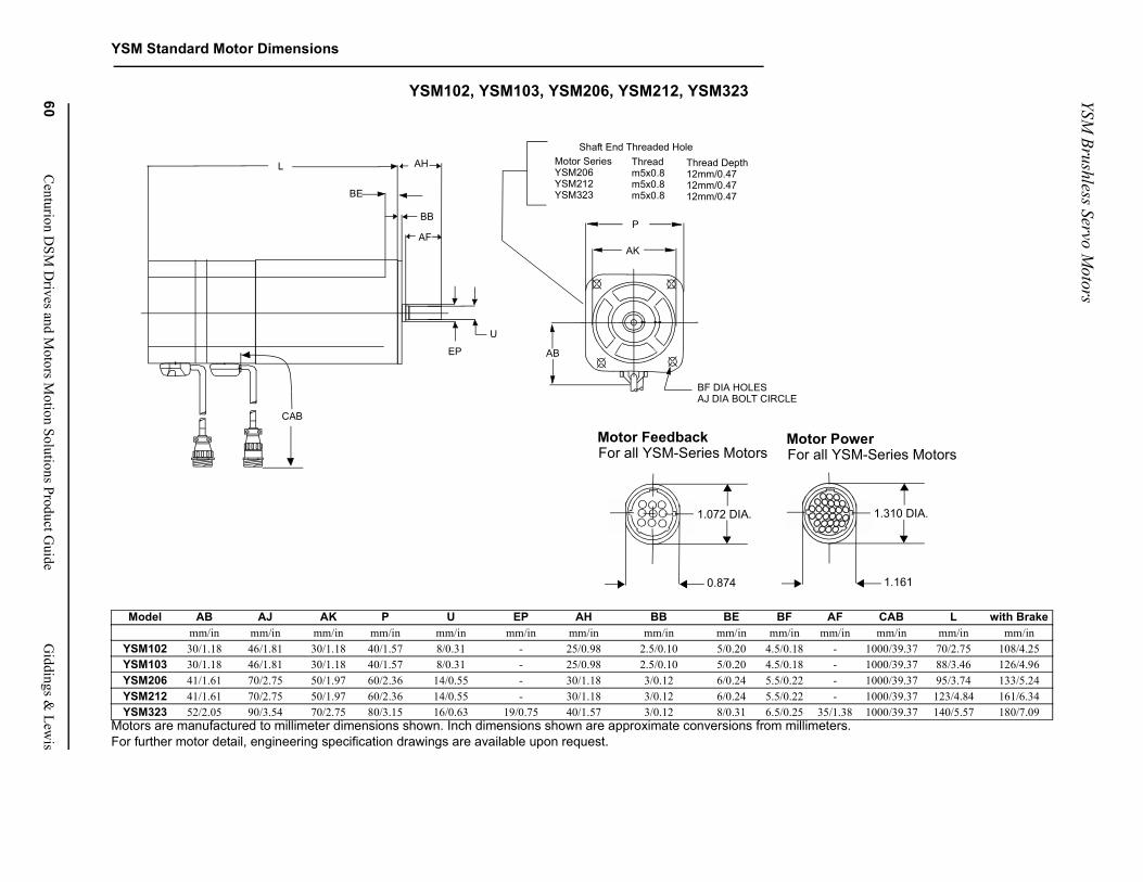
YSM Brushless Servo M
otors
60C
enturion DSM
Drives and M
otors Motion Solutions Product G
uideG
iddings & Lew
is
YSM Standard Motor Dimensions
CAB L with Brakemm/in mm/in mm/in
1000/39.37 70/2.75 108/4.251000/39.37 88/3.46 126/4.961000/39.37 95/3.74 133/5.241000/39.37 123/4.84 161/6.341000/39.37 140/5.57 180/7.09
1.310 DIA.
1.161
werM-Series Motors
YSM102, YSM103, YSM206, YSM212, YSM323
Motors are manufactured to millimeter dimensions shown. Inch dimensions shown are approximate conversions from millimeters.For further motor detail, engineering specification drawings are available upon request.
Model AB AJ AK P U EP AH BB BE BF AFmm/in mm/in mm/in mm/in mm/in mm/in mm/in mm/in mm/in mm/in mm/in
YSM102 30/1.18 46/1.81 30/1.18 40/1.57 8/0.31 - 25/0.98 2.5/0.10 5/0.20 4.5/0.18 -YSM103 30/1.18 46/1.81 30/1.18 40/1.57 8/0.31 - 25/0.98 2.5/0.10 5/0.20 4.5/0.18 -YSM206 41/1.61 70/2.75 50/1.97 60/2.36 14/0.55 - 30/1.18 3/0.12 6/0.24 5.5/0.22 -YSM212 41/1.61 70/2.75 50/1.97 60/2.36 14/0.55 - 30/1.18 3/0.12 6/0.24 5.5/0.22 -YSM323 52/2.05 90/3.54 70/2.75 80/3.15 16/0.63 19/0.75 40/1.57 3/0.12 8/0.31 6.5/0.25 35/1.38
1.072 DIA.
0.874
Motor FeedbackFor all YSM-Series Motors
Motor PoFor all YS
P
AK
AB
BF DIA HOLESAJ DIA BOLT CIRCLE
Motor SeriesYSM206YSM212YSM323
Threadm5x0.8m5x0.8m5x0.8
Thread Depth12mm/0.4712mm/0.4712mm/0.47
Shaft End Threaded Hole
EP
CAB
AF
BB
BE
AH
U
L
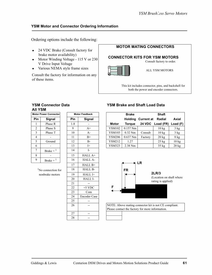
YSM Brushless Servo Motors
YSM Motor and Connector Ordering Information
Ordering options include the following:
• 24 VDC Brake (Consult factory for brake motor availability)
• Motor Winding Voltage - 115 V or 230 V Drive Input Voltage
• Various NEMA style frame sizes
Consult the factory for information on any of these items.
MOTOR MATING CONNECTORS
YSM Connector DataAll YSM
YSM Brake and Shaft Load Data
Motor Power Connector Motor Feedback Brake ShaftPin Signal Pin Signal Holding Current at Radial Axial
1 Phase R 1-8 - Motor Torque 24 VDC Load (FR) Load (F)2 Phase S 9 A+ YSM102 0.157 Nm 10 kg 3 kg3 Phase T 10 A- YSM103 0.32 Nm Consult 10 kg 3 kg4 - 11 B+ YSM206 0.637 Nm Factory 20 kg 8 kg5 Ground 12 B- YSM212 1.27 25 kg 10 kg6 - 13 I+ YSM323 2.38 Nm 35 kg 20 kg7 Brake + 1 14 I-
8 - 15 HALL A+9 Brake + 1 16 HALL A-
17 HALL B+1No connection for 18 HALL B-
nonbrake motors 19 HALL I+20 HALL I-21 --22 +5 VDC23 Com24 Encoder Case25 --26 -- NOTE: Above mating connector kit is not CE compliant.
Please contact the factory for more information. 27 --28 --
CONNECTOR KITS FOR YSM MOTORS
ALL YSM MOTORS
This kit includes connector, pins, and backshell for both the power and encoder connectors.
Consult factory to order.
2LR/3(Location on shaft where rating is applied)
FR
F
LR
Giddings & Lewis Centurion DSM Drives and Motors Motion Solutions Product Guide 61

FSM Medium Inertia Brushless Servo Motors
FSM Medium Inertia Brushless Servo Motors
Typical Applications Standard Features• Web and film processing • Compact design is mechanically interchangeable • Machine tool/metal cutting with the HSM family• Textile machinery Two frame sizes - six models• CAM replacements • Continuous torque from 31 to 245 lb-in (3.5 to 28 Characteristics Nm)• Higher inertia matching capability • Speeds to 4000 RPM• Heavy duty continuous operations • Ferrite permanent magnet rotors provide • Environmentally rugged approximately four times greater rotor inertia than
the HSM family for matching larger load inertias• Internal thermal switch indicates overheating• Motor mounted optical encoder includes 2000
quadrature pulses, index pulse and standard com-mutation channels for trapezoidal drives
• Water tight MS connections are compatible with standard cable assemblies; in addition, the extruded aluminum housing and environmental connectors provide an IP65 package (with the addition of the optional shaft seal kit)
• Economical, compact design ready for harsh envi-ronments
• Optional spring-set holding brakes available with 24 VDC or 90 VDC windings
• Axially trapped front bearing in a steel insert for long life at high speeds
• Vibration: 2.5 g peak 30-200 Hz• Shock: 10.0 g peak 6 msec duration• UL recognized
62 Centurion DSM Drives and Motors Motion Solutions Product Guide Giddings & Lewis
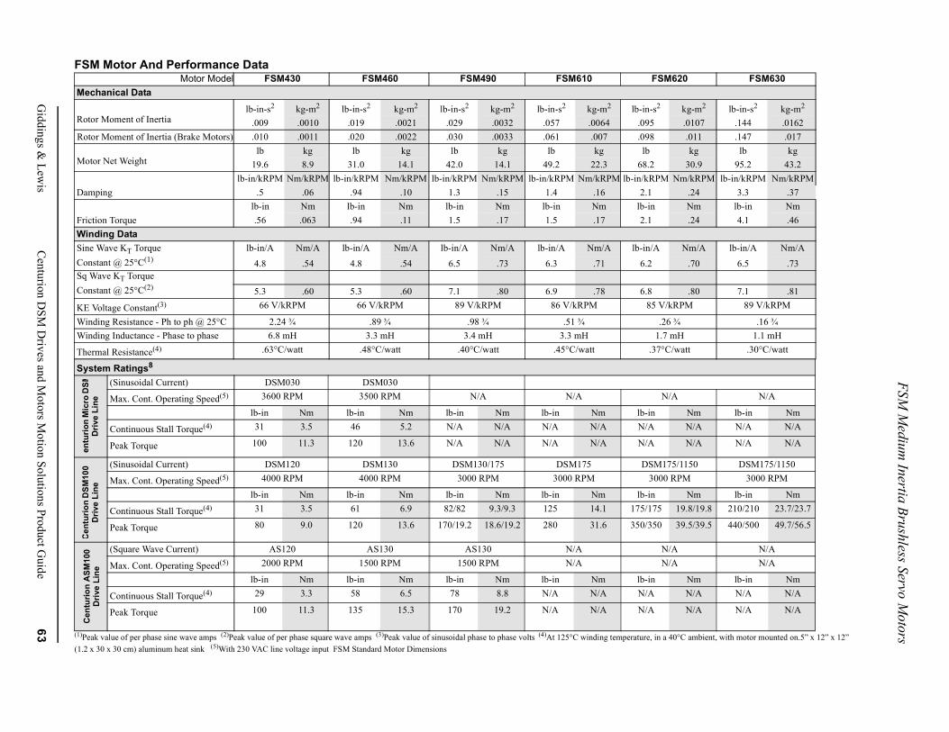
FSM M
edium Inertia Brushless Servo M
otors ambient, with motor mounted on.5” x 12” x 12”
0 FSM630
g-m2 lb-in-s2 kg-m2
.0107 .144 .0162.011 .147 .017kg lb kg
30.9 95.2 43.2/kRPM lb-in/kRPM Nm/kRPM.24 3.3 .37Nm lb-in Nm.24 4.1 .46
m/A lb-in/A Nm/A
.70 6.5 .73
.80 7.1 .81M 89 V/kRPM
.16 ¾1.1 mH
tt .30°C/watt
N/A
Nm lb-in NmN/A N/A N/A
N/A N/A N/A
150 DSM175/1150M 3000 RPM
Nm lb-in Nm.8/19.8 210/210 23.7/23.7
.5/39.5 440/500 49.7/56.5
N/AN/A
Nm lb-in NmN/A N/A N/A
N/A N/A N/A
Giddings &
Lewis
Centurion D
SM D
rives and Motors M
otion Solutions Product Guide
63
FSM Motor And Performance Data
(1)Peak value of per phase sine wave amps (2)Peak value of per phase square wave amps (3)Peak value of sinusoidal phase to phase volts (4)At 125°C winding temperature, in a 40°C(1.2 x 30 x 30 cm) aluminum heat sink (5)With 230 VAC line voltage input FSM Standard Motor Dimensions
Motor Model FSM430 FSM460 FSM490 FSM610 FSM62Mechanical Data lb-in-s2 kg-m2 lb-in-s2 kg-m2 lb-in-s2 kg-m2 lb-in-s2 kg-m2 lb-in-s2 kRotor Moment of Inertia .009 .0010 .019 .0021 .029 .0032 .057 .0064 .095Rotor Moment of Inertia (Brake Motors) .010 .0011 .020 .0022 .030 .0033 .061 .007 .098
lb kg lb kg lb kg lb kg lbMotor Net Weight 19.6 8.9 31.0 14.1 42.0 14.1 49.2 22.3 68.2
lb-in/kRPM Nm/kRPM lb-in/kRPM Nm/kRPM lb-in/kRPM Nm/kRPM lb-in/kRPM Nm/kRPM lb-in/kRPM NmDamping .5 .06 .94 .10 1.3 .15 1.4 .16 2.1
lb-in Nm lb-in Nm lb-in Nm lb-in Nm lb-inFriction Torque .56 .063 .94 .11 1.5 .17 1.5 .17 2.1Winding DataSine Wave KT Torque lb-in/A Nm/A lb-in/A Nm/A lb-in/A Nm/A lb-in/A Nm/A lb-in/A NConstant @ 25°C(1) 4.8 .54 4.8 .54 6.5 .73 6.3 .71 6.2Sq Wave KT TorqueConstant @ 25°C(2) 5.3 .60 5.3 .60 7.1 .80 6.9 .78 6.8
KE Voltage Constant(3) 66 V/kRPM 66 V/kRPM 89 V/kRPM 86 V/kRPM 85 V/kRP
Winding Resistance - Ph to ph @ 25°C 2.24 ¾ .89 ¾ .98 ¾ .51 ¾ .26 ¾Winding Inductance - Phase to phase 6.8 mH 3.3 mH 3.4 mH 3.3 mH 1.7 mH
Thermal Resistance(4) .63°C/watt .48°C/watt .40°C/watt .45°C/watt .37°C/wa
System Ratings8
(Sinusoidal Current) DSM030 DSM030
Max. Cont. Operating Speed(5) 3600 RPM 3500 RPM N/A N/A N/A
lb-in Nm lb-in Nm lb-in Nm lb-in Nm lb-in
Continuous Stall Torque(4) 31 3.5 46 5.2 N/A N/A N/A N/A N/A
Peak Torque 100 11.3 120 13.6 N/A N/A N/A N/A N/A
(Sinusoidal Current) DSM120 DSM130 DSM130/175 DSM175 DSM175/1
Max. Cont. Operating Speed(5) 4000 RPM 4000 RPM 3000 RPM 3000 RPM 3000 RP
lb-in Nm lb-in Nm lb-in Nm lb-in Nm lb-in
Continuous Stall Torque(4) 31 3.5 61 6.9 82/82 9.3/9.3 125 14.1 175/175 19
Peak Torque 80 9.0 120 13.6 170/19.2 18.6/19.2 280 31.6 350/350 39
(Square Wave Current) AS120 AS130 AS130 N/A N/A
Max. Cont. Operating Speed(5) 2000 RPM 1500 RPM 1500 RPM N/A N/A
lb-in Nm lb-in Nm lb-in Nm lb-in Nm lb-in
Continuous Stall Torque(4) 29 3.3 58 6.5 78 8.8 N/A N/A N/A
Peak Torque 100 11.3 135 15.3 170 19.2 N/A N/A N/A
Cen
turio
n M
icro
DSM
Driv
e Li
neC
entu
rion
DSM
100
Driv
e Li
neC
entu
rion
ASM
100
Driv
e Li
ne

FSM M
edium Inertia Brushless Servo M
otors
64C
enturion DSM
Drives and M
otors Motion Solutions Product G
uideG
iddings & Lew
is
.
S L with Brakem/in mm/in mm/in24X.24 194/7.64 257/10.1224X.24 272/10.71 335/13. 1924X.24 350/13.78 413/16.26.39X.32 255/10.04 326/12.83.39X.32 320/12.60 390/15.35.39X.32 420/16.53 490/19.29
L2 EYE BOLTS INSTALLEDON F-6100, 6200, AND 6300MOTORS ONLY
AH
X 15mm/.59 INCH DEEP THREADm X 20mm/.79 INCH DEEP THREAD
AB P
BF DIA HOLES - AJ DIA BOLT CIRCLE
U (4) EQ SP.ON A5.875/149 DAIM BC
MOTORS ARE MANUFACTURED TO MILLIMETER DIMENSIONS SHOWN. INCH DIMENSIONS SHOWN ARE APPROXIMATE CONVERSIONS FROM MILLIMETERSFOR FURTHER MOTOR DETAIL, ENGINEERING SPECIFICATION DRAWINGS ARE AVAILABLE UPON REQUEST.
Model AB AJ AK P U EP AH BB BF XDmm/in mm/in mm/in mm/in mm/in mm/in mm/in mm/in mm/in mm/in m
FSM430 102/4.02 145/5.71 110/4.33 127/5.00 19/.75 22.2/8.75 50/1.97 3/.12 10/.39 38/1.49 6X6/.FSM460 102/4.02 145/5.71 110/4.33 127/5.00 19/.75 22.2/8.75 50/1.97 3/.12 10/.39 38/1.49 6X6/.FSM490 102/4.02 145/5.71 110/4.33 127/5.00 19/.75 22.2/8.75 50/1.97 3/.12 10/.39 38/1.49 6X6/.FSM610 131/5.16 200/7.87 114.3/4.50 173/6.81 35/1.38 36.5/1.438 80/3.15 4.16 13.5/53 60/2.36 10X8/FSM620 131/5.16 200/7.87 114.3/4.50 173/6.81 35/1.38 36.5/1.438 80/3.15 4.16 13.5/53 60/2.36 10X8/FSM630 131/5.16 200/7.87 114.3/4.50 173/6.81 35/1.38 36.5/1.438 80/3.15 4.16 13.5/53 60/2.36 10X8/
NEMA 56C ON FSM400 MOTORS
S
U
BB
XD
AB
CONNECTOR FOR BRAKEOPTION THIS AREA
FSM 400 MOTORS: M6 X 1MM FSM 600 MOTORS: M8 X 1.25m
EP
BRAKE OPTION
0.875/22 DIA
4.500/114.3 DIA
0.25 INCH SHAFT SEAL (OPTIONAL,
0.625/15.9 DIA
1.41/36FULL DEPTH
0.12/30.64/16.3 NOT INCLUDED, RELIANCE P/N 0041-5060)
KEY SUPPLIED 0.1875/4.8SQUARE X 1.375/35 LONG
6.50/165 DIA
3/8-16 THR90 APART
2.06/52

FSM Medium Inertia Brushless Servo Motors
FSM Motor And Connector Ordering Information
Ordering options include the following:• 24 or 90 VDC Brake (Consult fac-
tory for brake motor availability)• Encoder Line Count - 1,000, 2,000,
5,000, 500, or 3,000 line• Special order motor windings avail-
able• Various NEMA style frame sizes
Consult the factory for information on any of these items. NOTE: Options are not available on all sizes. Optional configurations or encoder line counts have extended lead times and additional charges.
Motor Mating Connectors
FSM Motor Shaft Seal Kits:FSM400: M.1015.7904 (old # 401-34339-00)FSM600: M.1015.7905 (old # 401-34340-00)
Shaft seals generally require the presence of a lubricant to reduce premature wear.
NOTE: Above mating connector kits are not CE compliant. Please contact the factory for more information.
FSM Connector DataFSM400,600 ALL FSM
Motor Encoder Connector Motor Power Connector Motor Brake ConnectorPin Signal Pin Signal PIN SIGNALA A+ A R A BR+B A- B S B BR-C B+ C TD B- D MOTOR CASEE I+F I-G ENCODER CASEH ABSJ +5VDCK -5VDCL COMM COMN Hall BP Hall CR TS+S TS-T Hall A
MS Conn Kits FSM Motor Power:
FSM400
FSM600
StraightM.1015.7801(old # 401-34270-00) M.1015.7804(old # 401-34271-00)
Right AngleM.1015.7802(old # 401-34270-90) M.1015.7805(old # 401-34271-90)
MS Conn Kit FSM Encoder
FSMEncoderFeedback
BrakePower
Right AngleM.1015.7809(old # 401-34273-00)
StraightM.1015.7808(old # 401-34273-00)
Feedback:MS Conn Kit FSM Brake
Right AngleM.1015.7815(old # 401-34276-90)
StraightM.1015.7813(old # 401-34276-00)
Power:
Giddings & Lewis Centurion DSM Drives and Motors Motion Solutions Product Guide 65

HSM Low Inertia Brushless Servo Motors
HSM Low Inertia Brushless Servo Motors
Typical Applications Standard Features• “Smart” conveyors • Compact Design is mechanically interchangeable with the• Packaging machinery FSM400 and FSM600 motors• Punch press/material feeding • Five frame sizes – twelve models• Robotic pick and place • Continuous torque from 5 to 450 lb-in (0.5 to 50 Nm)• High duty cycle applications • Speeds to 6000 RPMCharacteristics • Neodymium-iron-boron permanent magnet rotors provide • High acceleration and peak low inertias and high accelerations
torques • Internal thermal switch indicates overheating• High speed point-to-point posi- • Motor mounted optical encoder includes 2000 quadrature
tioning pulses, index pulse and standard commutation channels• Environmentally rugged for trapezoidal drives
• Watertight MS connections are compatible with standard cable assemblies; in addition, the extruded aluminum hous-ing and environmental connectors provide an IP65 package (with the addition of the optional shaft seal kit)
• Economical, compact design ready for harsh environments• Optional spring-set holding brakes available with 24 VDC
or 90 VDC windings• Axially trapped front bearing (in a steel insert in H-4000, H-
6000 and H-8000 series) for long life at high speeds• Vibration: 2.5 g peak 30-2000 H• Shock: 10.0 g peak 6 msec duration• UL recognized
66 Centurion DSM Drives and Motors Motion Solutions Product Guide Giddings & Lewis
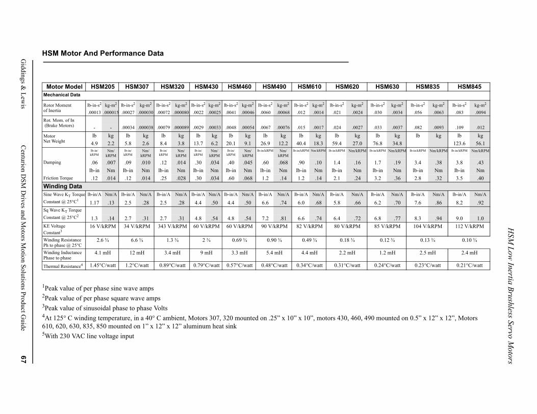
HSM
Low Inertia Brushless Servo M
otors
Giddings &
Lewis
Centurion D
SM D
rives and Motors M
otion Solutions Product Guide
67
0 mounted on 0.5” x 12” x 12”, Motors
HSM630 HSM835 HSM845
lb-in-s2 kg-m2 lb-in-s2 kg-m2 lb-in-s2 kg-m2
.030 .0034 .056 .0063 .083 .0094
.033 .0037 .082 .0093 .109 .012
lb kg lb kg lb kg76.8 34.8 123.6 56.1
lb-in/kRPM Nm/kRPM lb-in/kRPM Nm/kRPM lb-in/kRPM Nm/kRPM
1.7 .19 3.4 .38 3.8 .43lb-in Nm lb-in Nm lb-in Nm3.2 .36 2.8 .32 3.5 .40
lb-in/A Nm/A lb-in/A Nm/A lb-in/A Nm/A
6.2 .70 7.6 .86 8.2 .92
6.8 .77 8.3 .94 9.0 1.085 V/kRPM 104 V/kRPM 112 V/kRPM
0.12 ¾ 0.13 ¾ 0.10 ¾
1.2 mH 2.5 mH 2.4 mH
0.24°C/watt 0.23°C/watt 0.21°C/watt
HSM Motor And Performance Data
1Peak value of per phase sine wave amps 2Peak value of per phase square wave amps 3Peak value of sinusoidal phase to phase Volts 4At 125° C winding temperature, in a 40° C ambient, Motors 307, 320 mounted on .25” x 10” x 10”, motors 430, 460, 49610, 620, 630, 835, 850 mounted on 1” x 12” x 12” aluminum heat sink 5With 230 VAC line voltage input
Motor Model HSM205 HSM307 HSM320 HSM430 HSM460 HSM490 HSM610 HSM620Mechanical Data
Rotor Moment lb-in-s2 kg-m2 lb-in-s2 kg-m2 lb-in-s2 kg-m2 lb-in-s2 kg-m2 lb-in-s2 kg-m2 lb-in-s2 kg-m2 lb-in-s2 kg-m2 lb-in-s2 kg-m2
of Inertia .00013 .000015 .00027 .000030 .00072 .000080 .0022 .00025 .0041 .00046 .0060 .00068 .012 .0014 .021 .0024
Rot. Mom. of In (Brake Motors) - - .00034 .000038 .00079 .000089 .0029 .00033 .0048 .00054 .0067 .00076 .015 .0017 .024 .0027
Motor lb kg lb kg lb kg lb kg lb kg lb kg lb kg lb kgNet Weight 4.9 2.2 5.8 2.6 8.4 3.8 13.7 6.2 20.1 9.1 26.9 12.2 40.4 18.3 59.4 27.0
lb-in/kRPM
Nm/kRPM
lb-in/kRPM
Nm/kRPM
lb-in/kRPM
Nm/kRPM
lb-in/kRPM
Nm/kRPM
lb-in/kRPM
Nm/kRPM
lb-in/kRPM Nm/kRPM
lb-in/kRPM Nm/kRPM lb-in/kRPM Nm/kRPM
Damping .06 .007 .09 .010 .12 .014 .30 .034 .40 .045 .60 .068 .90 .10 1.4 .16lb-in Nm lb-in Nm lb-in Nm lb-in Nm lb-in Nm lb-in Nm lb-in Nm lb-in Nm
Friction Torque .12 .014 .12 .014 .25 .028 .30 .034 .60 .068 1.2 .14 1.2 .14 2.1 .24Winding DataSine Wave KT Torque lb-in/A Nm/A lb-in/A Nm/A lb-in/A Nm/A lb-in/A Nm/A lb-in/A Nm/A lb-in/A Nm/A lb-in/A Nm/A lb-in/A Nm/AConstant @ 25°C1 1.17 .13 2.5 .28 2.5 .28 4.4 .50 4.4 .50 6.6 .74 6.0 .68 5.8 .66Sq Wave KT TorqueConstant @ 25°C2 1.3 .14 2.7 .31 2.7 .31 4.8 .54 4.8 .54 7.2 .81 6.6 .74 6.4 .72KE Voltage Constant3
16 V/kRPM 34 V/kRPM 343 V/kRPM 60 V/kRPM 60 V/kRPM 90 V/kRPM 82 V/kRPM 80 V/kRPM
Winding ResistancePh to phase @ 25°C
2.6 ¾ 6.6 ¾ 1.3 ¾ 2 ¾ 0.69 ¾ 0.90 ¾ 0.49 ¾ 0.18 ¾
Winding InductancePhase to phase
4.1 mH 12 mH 3.4 mH 9 mH 3.3 mH 5.4 mH 4.4 mH 2.2 mH
Thermal Resistance4 1.45°C/watt 1.2°C/watt 0.89°C/watt 0.79°C/watt 0.57°C/watt 0.48°C/watt 0.34°C/watt 0.31°C/watt
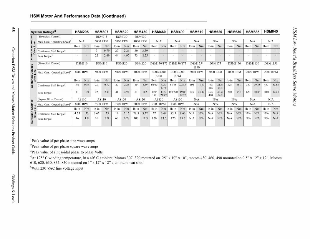
HSM
Low Inertia Brushless Servo M
otors
68C
enturion DSM
Drives and M
otors Motion Solutions Product G
uideG
iddings & Lew
is
HSM Motor And Performance Data (Continued)
unted on 0.5” x 12” x 12”, Motors
HSM630 HSM835 HSM845
N/A N/A N/Ab-in Nm lb-in Nm lb-in Nm
- - - - - -- - - - - -
DSM1150 DSM1150 DSM1150
3000 RPM 2000 RPM 2000 RPM
b-in Nm lb-in Nm lb-in Nm325 36.7 350 39.55 450 50.85
700 79.1 620 70.06 1100 124.3
N/A N/A N/AN/A N/A N/A
b-in Nm lb-in Nm lb-in Nm/A N/A N/A N/A N/A N/A/A N/A N/A N/A N/A N/A
1Peak value of per phase sine wave amps 2Peak value of per phase square wave amps 3Peak value of sinusoidal phase to phase Volts 4At 125° C winding temperature, in a 40° C ambient, Motors 307, 320 mounted on .25” x 10” x 10”, motors 430, 460, 490 mo610, 620, 630, 835, 850 mounted on 1” x 12” x 12” aluminum heat sink 5With 230 VAC line voltage input
System Ratings8 HSM205 HSM307 HSM320 HSM430 HSM460 HSM490 HSM610 HSM620(Sinusoidal Current) DSM015 DSM030 DSM030 Max. Cont. Operating Speed5 N/A 5000 RPM 5000 RPM 4000 RPM N/A N/A N/A N/A
lb-in Nm lb-in Nm lb-in Nm lb-in Nm lb-in Nm lb-in Nm lb-in Nm lb-in Nm lContinuous Stall Torque4, - - 7 0.79 20 2.26 30 3.39 - - - - - - - -
Peak Torque9 - - 22 2.49 44 4.97 73 8.25 - - - - - - - -
(Sinusoidal Current) DSM110 DSM110 DSM120 DSM120 DSM130/175 DSM130/175 DSM175/1150
DSM175
Max. Cont. Operating Speed5 6000 RPM 5000 RPM 5000 RPM 4000 RPM 4000/4000 RPM
3000/3000 RPM
3000 RPM 3000 RPM
lb-in Nm lb-in Nm lb-in Nm lb-in Nm lb-in Nm lb-in Nm lb-in Nm lb-in Nm lContinuous Stall Torque4, 5.0 0.56 7.0 0.79 20 2.26 30 3.39 60/60 6.78/
6.7888/88 9.9/9.9 100 11.30 190/
21621.4/24.4
Peak Torque 11 1.24 22 2.48 44 4.97 73 8.2 120/190
13.5/21.47
180/270 19.8/122.7
225 25.42 360/480
40.7/54.2
(Square Wave Current) AS110 AS110 AS120 AS120 AS130 AS130 N/A N/AMax. Cont. Operating Speed5 6000 RPM 3500 RPM 3500 RPM 2000 RPM 2000 RPM 1500 RPM N/A N/A
lb-in Nm lb-in Nm lb-in Nm lb-in Nm lb-in Nm lb-in Nm lb-in Nm lb-in Nm lContinuous Stall Torque4, 4.75 .53 6.65 .75 19 2.15 28.5 3.22 57 6.44 85.5 9.66 N/A N/A N/A N/A N
Peak Torque 16 1.8 26 2.9 60 6.78 100 11.3 120 13.5 175 19.7 N/A N/A N/A N/A N
entu
rion
Mic
ro D
SMD
rive
Line
Cen
turio
n D
SM10
0 D
rive
Line
Cen
turio
n A
SM10
0 D
rive
Line
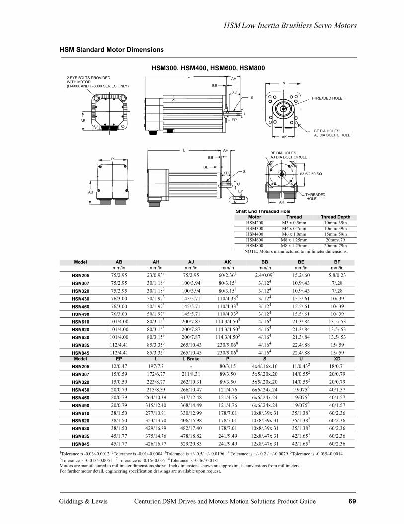
HSM Low Inertia Brushless Servo Motors
HSM Standard Motor Dimensions
HSM300, HSM400, HSM600, HSM800
1Tolerance is -0.03/-0.0012 2Tolerance is -0.01/-0.0004 3Tolerance is +/- 0.5/ +/- 0.0196 4 Tolerance is +/- 0.2 / +/-0.0079 5Tolerance is -0.035/-0.0014 6Tolerance is -0.013/-0.0051 7 Tolerance is -0.16/-0.006 8Tolerance is -0.46/-0.0181 Motors are manufactured to millimeter dimensions shown. Inch dimensions shown are approximate conversions from millimeters. For further motor detail, engineering specification drawings are available upon request.
Shaft End Threaded HoleMotor Thread Thread Depth
HSM200 M3 x 0.5mm 10mm/.39inHSM300 M4 x 0.7mm 10mm/.39inHSM400 M6 x 1.0mm 15mm/.59inHSM600 M8 x 1.25mm 20mm/.79HSM800 M8 x 1.25mm 20mm/.79in
NOTE: Motors manufactured to millimeter dimensions.
Model AB AH AJ AK BB BE BFmm/in mm/in mm/in mm/in mm/in mm/in mm/in
HSM205 75/2.95 23/0.933 75/2.95 60/2.361 2.4/0.094 15.2/.60 5.8/0.23HSM307 75/2.95 30/1.183 100/3.94 80/3.151 3/.124 10.9/.43 7/.28HSM320 75/2.95 30/1.183 100/3.94 80/3.151 3/.124 10.9/.43 7/.28HSM430 76/3.00 50/1.973 145/5.71 110/4.335 3/.124 15.5/.61 10/.39HSM460 76/3.00 50/1.973 145/5.71 110/4.335 3/.124 15.5/.61 10/.39HSM490 76/3.00 50/1.973 145/5.71 110/4.335 3/.124 15.5/.61 10/.39HSM610 101/4.00 80/3.153 200/7.87 114.3/4.505 4/.164 21.3/.84 13.5/.53HSM620 101/4.00 80/3.153 200/7.87 114.3/4.505 4/.164 21.3/.84 13.5/.53HSM630 101/4.00 80/3.153 200/7.87 114.3/4.505 4/.164 21.3/.84 13.5/.53HSM835 112/4.41 85/3.353 265/10.43 230/9.068 4/.164 22.4/.88 15/.59HSM845 112/4.41 85/3.353 265/10.43 230/9.068 4/.164 22.4/.88 15/.59Model EP L L Brake P S U XD
HSM205 12/0.47 197/7.7 - 80/3.15 4x4/.16x.16 11/0.432 18/0.71HSM307 15/0.59 172/6.77 211/8.31 89/3.50 5x5/.20x.20 14/0.552 20/0.79HSM320 15/0.59 223/8.77 262/10.31 89/3.50 5x5/.20x.20 14/0.552 20/0.79HSM430 20/0.79 213/8.39 266/10.47 121/4.76 6x6/.24x.24 19/0756 40/1.57HSM460 20/0.79 264/10.39 317/12.48 121/4.76 6x6/.24x.24 19/0756 40/1.57HSM490 20/0.79 315/12.40 368/14.49 121/4.76 6x6/.24x.24 19/0756 40/1.57HSM610 38/1.50 277/10.91 330/12.99 178/7.01 10x8/.39x.31 35/1.387 60/2.36HSM620 38/1.50 353/13.90 406/15.98 178/7.01 10x8/.39x.31 35/1.387 60/2.36HSM630 38/1.50 429/16.89 482/17.40 178/7.01 10x8/.39x.31 35/1.387 60/2.36HSM835 45/1.77 375/14.76 478/18.82 241/9.49 12x8/.47x.31 42/1.657 60/2.36HSM845 45/1.77 426/16.77 529/20.83 241/9.49 12x8/.47x.31 42/1.657 60/2.36
L
S
U
P
P
AB
BE
BB
AHL
SXD
U
EP
BF DIA HOLESAJ DIA BOLT CIRCLE
63.5/2.50 SQ
THREADEDHOLE
2 EYE BOLTS PROVIDEDWITH MOTOR(H-6000 AND H-8000 SERIES ONLY) BE
AH
XD
BF DIA HOLESAJ DIA BOLT CIRCLE
AB EP
THREADED HOLE
AK
AK
Giddings & Lewis Centurion DSM Drives and Motors Motion Solutions Product Guide 69
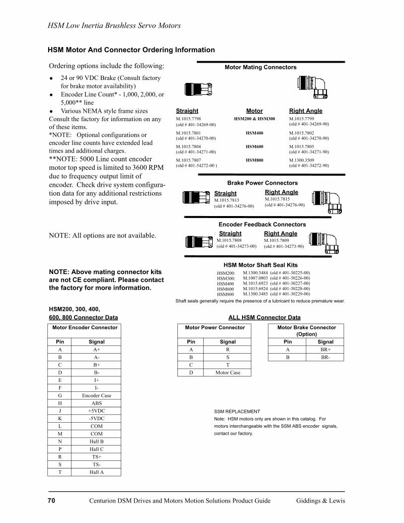
HSM Low Inertia Brushless Servo Motors
HSM Motor And Connector Ordering Information
Ordering options include the following:
• 24 or 90 VDC Brake (Consult factory for brake motor availability)
• Encoder Line Count* - 1,000, 2,000, or 5,000** line
• Various NEMA style frame sizesConsult the factory for information on any of these items. *NOTE: Optional configurations or encoder line counts have extended lead times and additional charges.**NOTE: 5000 Line count encoder motor top speed is limited to 3600 RPM due to frequency output limit of encoder. Check drive system configura-tion data for any additional restrictions imposed by drive input.
Motor Mating Connectors
Straight Motor Right AngleM.1015.7798(old # 401-34269-00)
HSM200 & HSM300 M.1015.7799(old # 401-34269-90)
M.1015.7801(old # 401-34270-00)
HSM400 M.1015.7802(old # 401-34270-90)
M.1015.7804(old # 401-34271-00)
HSM600 M.1015.7805(old # 401-34271-90)
M.1015.7807(old # 401-34272-00 )
HSM800 M.1300.3509(old # 401-34272-90)
NOTE: All options are not available.
NOTE: Above mating connector kits are not CE compliant. Please contact the factory for more information.
HSM Motor Shaft Seal Kits
HSM200, 300, 400, 600, 800 Connector Data ALL HSM Connector Data
Motor Encoder Connector Motor Power Connector Motor Brake Connector (Option)
Pin Signal Pin Signal Pin SignalA A+ A R A BR+B A- B S B BR-C B+ C TD B- D Motor CaseE I+F I-G Encoder CaseH ABSJ +5VDCK -5VDCL COMM COMN Hall BP Hall CR TS+S TS-T Hall A
StraightM.1015.7813(old # 401-34276-00)
Right AngleM.1015.7815(old # 401-34276-90)
Brake Power Connectors
StraightM.1015.7808(old # 401-34273-00)
Right AngleM.1015.7809(old # 401-34273-90)
Encoder Feedback Connectors
HSM200:HSM300:HSM400HSM600HSM800
M.1300.3484 (old # 401-30225-00)M.1007.0803 (old # 401-30226-00)M.1015.6923 (old # 401-30227-00)M.1015.6924 (old # 401-30228-00)M.1300.3485 (old # 401-30229-00)
Shaft seals generally require the presence of a lubricant to reduce premature wear.
SSM REPLACEMENTNote: HSM motors only are shown in this catalog. Formotors interchangeable with the SSM ABS encoder signals,contact our factory.
70 Centurion DSM Drives and Motors Motion Solutions Product Guide Giddings & Lewis
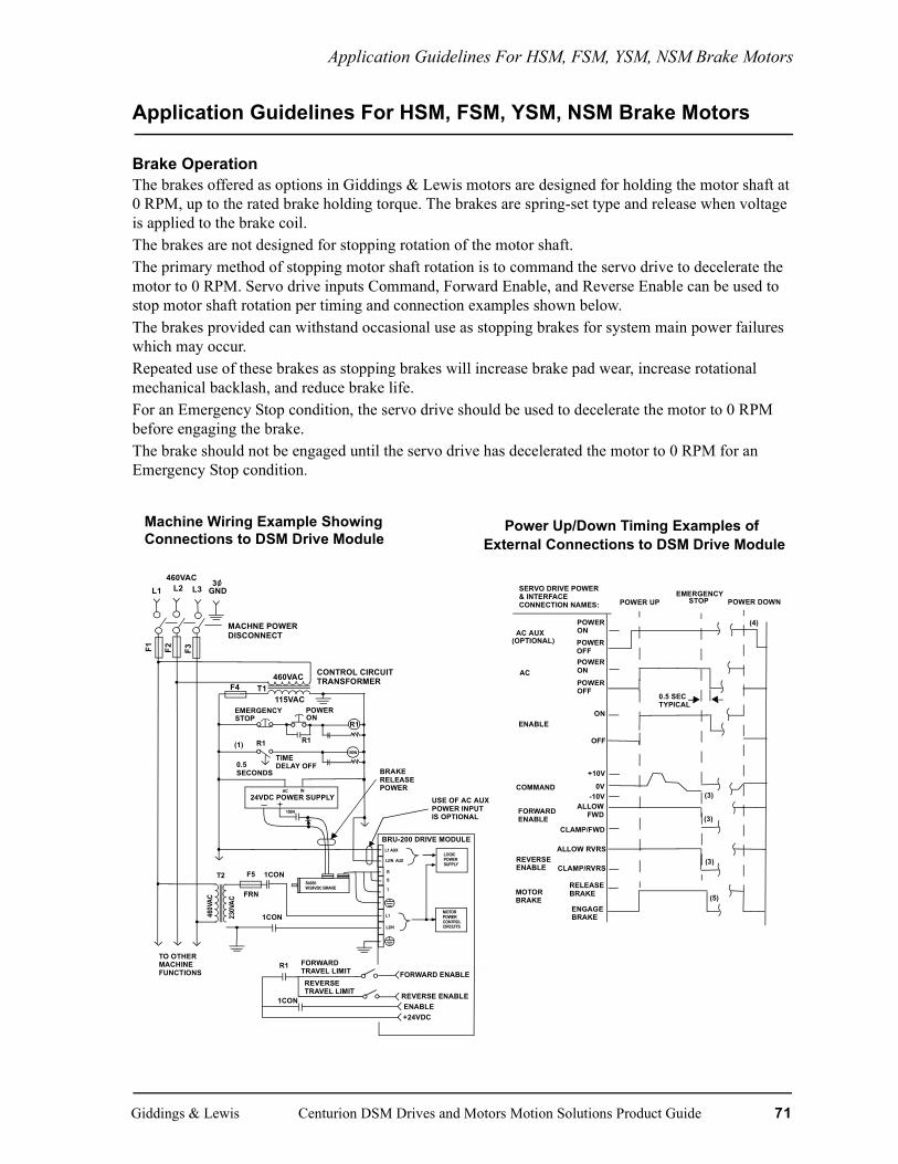
Application Guidelines For HSM, FSM, YSM, NSM Brake Motors
Application Guidelines For HSM, FSM, YSM, NSM Brake Motors
Brake OperationThe brakes offered as options in Giddings & Lewis motors are designed for holding the motor shaft at 0 RPM, up to the rated brake holding torque. The brakes are spring-set type and release when voltage is applied to the brake coil.The brakes are not designed for stopping rotation of the motor shaft.The primary method of stopping motor shaft rotation is to command the servo drive to decelerate the motor to 0 RPM. Servo drive inputs Command, Forward Enable, and Reverse Enable can be used to stop motor shaft rotation per timing and connection examples shown below.The brakes provided can withstand occasional use as stopping brakes for system main power failures which may occur. Repeated use of these brakes as stopping brakes will increase brake pad wear, increase rotational mechanical backlash, and reduce brake life.For an Emergency Stop condition, the servo drive should be used to decelerate the motor to 0 RPM before engaging the brake. The brake should not be engaged until the servo drive has decelerated the motor to 0 RPM for an Emergency Stop condition.
Machine Wiring Example ShowingConnections to DSM Drive Module
Power Up/Down Timing Examples ofExternal Connections to DSM Drive Module
460VACL1 L2 L3
3GND
MACHNE POWERDISCONNECT
F1 F2 F3
460VAC
115VAC
CONTROL CIRCUITTRANSFORMER
F4 T1
EMERGENCYSTOP
POWERON
R1
100N
R1(1)
TIMEDELAY OFF
R1
0.5SECONDS
24VDC POWER SUPPLY
100N
BRAKERELEASEPOWER
USE OF AC AUXPOWER INPUTIS OPTIONAL
BRU-200 DRIVE MODULE
F5
L1 AUX
L2/N AUX
R
S
T
L2/N
L1
LOGICPOWERSUPPLY
MOTORPOWERCONTROLCIRCUITS
460V
AC
230V
AC
T2
FRN
1CON
1CON
S4030W/24VDC BRAKE
R1 FORWARDTRAVEL LIMITREVERSETRAVEL LIMIT
1CON
FORWARD ENABLE
REVERSE ENABLEENABLE+24VDC
AC IN
TO OTHERMACHINEFUNCTIONS
SERVO DRIVE POWER& INTERFACECONNECTION NAMES:
AC AUX
AC
ENABLE
COMMAND
FORWARDENABLE
REVERSEENABLE
MOTORBRAKE
POWERONPOWEROFFPOWERONPOWEROFF
ON
OFF
+10V
0V-10V
ALLOWFWD
ALLOW RVRS
CLAMP/FWD
CLAMP/RVRS
RELEASEBRAKE
ENGAGEBRAKE
POWER UPEMERGENCY
STOP POWER DOWN
(OPTIONAL)
0.5 SECTYPICAL
(3)
(3)
(3)
(5)
(4)
Giddings & Lewis Centurion DSM Drives and Motors Motion Solutions Product Guide 71

Application Guidelines For HSM, FSM, YSM, NSM Brake Motors
This drawing is intended as an example only. It does not show all interlocks required for safe operation of the equipment.(1) Time delay off contacts allow time for drive module to decelerate motor to 0 RPM before power to motor control circuits is removed.
(2) Relay R1 contacts may be connected to For-ward and Reverse Enable interface circuits as shown when no position controller is used. When the BRU-200 is used with a PRO-Series or CNC Position Controller, these R1 contacts would be connected to the position controller emergency stop input.
(3) For emergency stop, Command should be immediately set to 0.0 VDC and/or For-ward and Reverse Enable inputs set to clamp, to decelerate motor to 0 RPM before power to drive module is removed.(4) The only requirement for non-emer-gency power down sequence is to insure that the motor shaft is at 0 RPM before engaging the optional motor brake.(5) The brake available as an option on H-Series and F-Series motors is a holding brake, and is not rated for repeated use as a stopping brake.
72 Centurion DSM Drives and Motors Motion Solutions Product Guide Giddings & Lewis
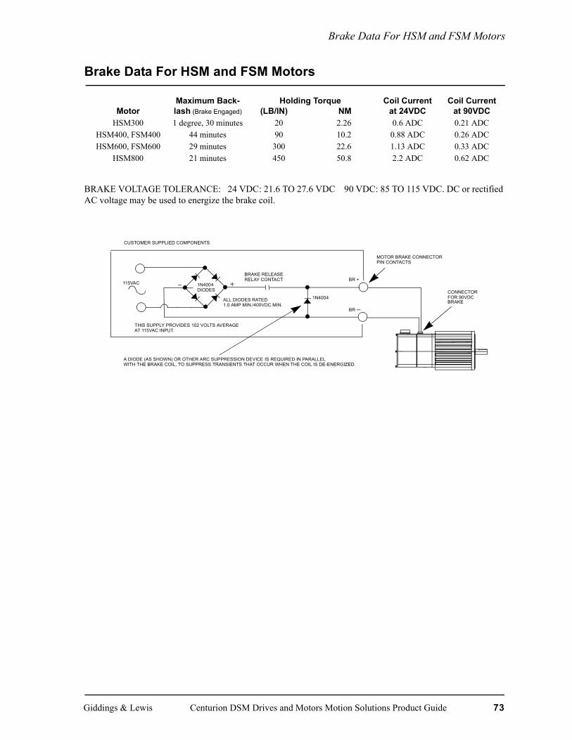
Brake Data For HSM and FSM Motors
Brake Data For HSM and FSM Motors
BRAKE VOLTAGE TOLERANCE: 24 VDC: 21.6 TO 27.6 VDC 90 VDC: 85 TO 115 VDC. DC or rectified AC voltage may be used to energize the brake coil.
MotorMaximum Back-lash (Brake Engaged)
Holding Torque(LB/IN) NM
Coil Currentat 24VDC
Coil Currentat 90VDC
HSM300 1 degree, 30 minutes 20 2.26 0.6 ADC 0.21 ADCHSM400, FSM400 44 minutes 90 10.2 0.88 ADC 0.26 ADCHSM600, FSM600 29 minutes 300 22.6 1.13 ADC 0.33 ADC
HSM800 21 minutes 450 50.8 2.2 ADC 0.62 ADC
1N4004DIODES
115VAC
1N4004
THIS SUPPLY PROVIDES 102 VOLTS AVERAGEAT 115VAC INPUT.
ALL DIODES RATED1.0 AMP MIN./400VDC MIN.
BRAKE RELEASERELAY CONTACT BR +
BR
MOTOR BRAKE CONNECTORPIN CONTACTS
CUSTOMER SUPPLIED COMPONENTS
A DIODE (AS SHOWN) OR OTHER ARC SUPPRESSION DEVICE IS REQUIRED IN PARALLELWITH THE BRAKE COIL, TO SUPPRESS TRANSIENTS THAT OCCUR WHEN THE COIL IS DE-ENERGIZED.
CONNECTORFOR 90VDCBRAKE
Giddings & Lewis Centurion DSM Drives and Motors Motion Solutions Product Guide 73

Standard Motor Radial Load Force Ratings For HSM and FSM Motors
Standard Motor Radial Load Force Ratings For HSM and FSM Motors
(Loads applied at center of shaft) For 20,000 HR Bearing Life
NOTE: Motors are capable of carrying an axial load in most applications per the following general guidelines which should be used only as an approximation. Please consult with Giddings & Lewis to discuss your application loads to ensure the proper selection of motors.
• When motor shaft has no radial load, Axial load rating = 100% of radial load rating from table above.
• When motor shaft has both a radial load and an axial load, axial load rating = 44% of radial load rating from table above.
500 RPM 1000 RPM 2000 RPM 3000 RPM 4000 RPM 5000 RPM 6000 RPMlb kg lb kg lb kg lb kg lb kg lb kg lb kg
NSM2302 17 8 16 7 14 6 12 6 11 5 9 4 8 3NSM2304 19 9 17 8 15 7 14 6 12 5 10 5 8 4NSM3406 103 47 82 37 65 29 56 26 51 23 48 22 45 20HSM205 105 47.7 84 38.2 66 30.0 58 26.4 53 24.1 49 22.3 45 20.5HSM307 113 51.4 90 40.9 71 32.3 62 28.2 56 25.5 53 24.1
NSM3412 113 51 89 40 71 32 62 28 56 26 53 24 49 22HSM320 126 57.3 101 45.9 79 21.6 69 31.4 63 28.6 59 26.8
NSM4214 137 62 109 49 86 39 76 34 68 31 64 29NSM4220 146 66 116 52 92 41 80 36 73 33 68 31HSM430 169 76.8 152 69.1 120 54.5 105 47.7 95 43.2
NSM5630 188 85 149 67 118 53 103 47 94 43NSM5637 197 89 156 71 124 56 108 49 98 45FSM430 203 92.3 161 73.2 129 58.6 113 51.4 101 45.9
NSM5647 203 92 161 73 128 58 112 51HSM460 205 93.2 164 74.5 129 58.6 113 51.4 103 46.8FSM460 229 104.1 184 83.6 144 65.5 126 57.3 116 52.7HSM490 215 97.7 173 78.6 137 62.3 118 53.6 108 49.1FSM490 244 110.9 194 88.2 154 70.0 133 60.5 121 55.0HSM610 435 197.7 345 156.8 274 124.5 240 109.1FSM610 428 194.5 341 155.0 268 121.8 236 107.3HSM620 469 213.2 375 170.5 296 134.5 259 117.7FSM620 465 211.4 368 167.3 293 133.2 255 115.9HSM630 495 225.0 390 177.3 311 141.4 270 122.7FSM630 495 225.0 390 177.3 311 141.4 270 122.7HSM835 495 225.0 394 179.1 311 141.4HSM845 518 235.4 413 187.7 326 148.2
Radial Load Force - lbs (Kg) applied at center
74 Centurion DSM Drives and Motors Motion Solutions Product Guide Giddings & Lewis