gic stream protocol interface - arm architectureinfocenter.arm.com/help/topic/com.arm.doc.ecm... ·...
TRANSCRIPT

Document Number: ARM-ECM-0495013 Non-Confidential
Version: A Page 1 of 32
Application Note GIC Stream Protocol interface
Version A
Non-Confidential

Document Number: ARM-ECM-0495013 Non-Confidential
Version: A Page 2 of 32
GIC Stream Protocol interface
Copyright © 2016 ARM Limited or its affiliates. All rights reserved.
Release Information
The following changes have been made to this Application Note.
Document History
Date Issue Confidentiality Change
22/02/2016 A Non-Confidential First release
Non-Confidential Proprietary Notice
This document is protected by copyright and other related rights and the practice or
implementation of the information contained in this document may be protected by one or
more patents or pending patent applications. No part of this document may be
reproduced in any form by any means without the express prior written permission of
ARM. No license, express or implied, by estoppel or otherwise to any intellectual
property rights is granted by this document unless specifically stated.
Your access to the information in this document is conditional upon your acceptance that
you will not use or permit others to use the information for the purposes of determining
whether implementations infringe any third party patents.
THIS DOCUMENT IS PROVIDED “AS IS”. ARM PROVIDES NO REPRESENTATIONS
AND NO WARRANTIES, EXPRESS, IMPLIED OR STATUTORY, INCLUDING,
WITHOUT LIMITATION, THE IMPLIED WARRANTIES OF MERCHANTABILITY,
SATISFACTORY QUALITY, NON-INFRINGEMENT OR FITNESS FOR A PARTICULAR
PURPOSE WITH RESPECT TO THE DOCUMENT. For the avoidance of doubt, ARM
makes no representation with respect to, and has undertaken no analysis to identify or
understand the scope and content of, third party patents, copyrights, trade secrets, or
other rights.
This document may include technical inaccuracies or typographical errors.
TO THE EXTENT NOT PROHIBITED BY LAW, IN NO EVENT WILL ARM BE LIABLE
FOR ANY DAMAGES, INCLUDING WITHOUT LIMITATION ANY DIRECT, INDIRECT,
SPECIAL, INCIDENTAL, PUNITIVE, OR CONSEQUENTIAL DAMAGES, HOWEVER
CAUSED AND REGARDLESS OF THE THEORY OF LIABILITY, ARISING OUT OF ANY
USE OF THIS DOCUMENT, EVEN IF ARM HAS BEEN ADVISED OF THE POSSIBILITY
OF SUCH DAMAGES.
This document consists solely of commercial items. You shall be responsible for ensuring
that any use, duplication or disclosure of this document complies fully with any relevant
export laws and regulations to assure that this document or any portion thereof is not
exported, directly or indirectly, in violation of such export laws. Use of the word “partner”
in reference to ARM’s customers is not intended to create or refer to any partnership
relationship with any other company. ARM may make changes to this document at any
time and without notice.
If any of the provisions contained in these terms conflict with any of the provisions of any
signed written agreement covering this document with ARM, then the signed written
agreement prevails over and supersedes the conflicting provisions of these terms. This
document may be translated into other languages for convenience, and you agree that if
there is any conflict between the English version of this document and any translation, the
terms of the English version of the Agreement shall prevail.

Document Number: ARM-ECM-0495013 Non-Confidential
Version: A Page 3 of 32
Words and logos marked with ® or ™ are registered trademarks or trademarks of ARM
Limited or its affiliates in the EU and/or elsewhere. All rights reserved. Other brands and
names mentioned in this document may be the trademarks of their respective owners.
Please follow ARM’s trademark usage guidelines at http://www.arm.com/about/trademark-usage-
guidelines.php
Copyright © 2016, ARM Limited or its affiliates. All rights reserved.
ARM Limited. Company 02557590 registered in England.
110 Fulbourn Road, Cambridge, England CB1 9NJ.
LES-PRE-20349

Document Number: ARM-ECM-0495013 Non-Confidential
Version: A Page 4 of 32
Confidentiality Status
This document is Non-Confidential. The right to use, copy and disclose this document
may be subject to license restrictions in accordance with the terms of the agreement
entered into by ARM and the party that ARM delivered this document to.
Product Status
The information in this document is Final, that is for a developed product.
Web Address
http://www.arm.com

Document Number: ARM-ECM-0495013 Non-Confidential
Version: A Page 5 of 32
Contents
GIC Stream Protocol interface
1 Conventions and Feedback ....................................................................................... 6
2 Preface ......................................................................................................................... 7
2.1 References ............................................................................................................. 8
2.2 Terms and abbreviations ........................................................................................ 9
3 Introduction ............................................................................................................... 10
3.1 Introducing the GIC Stream Protocol interface..................................................... 11
3.2 AXI Stream Protocol ............................................................................................. 12
4 GICv3 .......................................................................................................................... 13
4.1 Overview of GICv3 commands ............................................................................. 14
4.2 A typical interrupt sequence ................................................................................. 16
4.3 An interrupt being retrieved from a CPU interface ............................................... 18
4.4 Arrival of a Higher Priority Interrupt ...................................................................... 20
4.5 SGI ........................................................................................................................ 22
4.6 Clearing group enables in CPU interface ............................................................. 23
4.7 Power Management ............................................................................................. 24
5 GICv4: Directly Injected Virtual Interrupts ............................................................. 27
5.1 Overview of GICv4 commands ............................................................................. 28
5.2 A typical virtual interrupt sequence ...................................................................... 29
5.3 De-asserted virtual interrupt ................................................................................. 30
5.4 Interaction between physical interrupts and virtual interrupts .............................. 31
5.5 Mixing GICv3 and GICv4 ...................................................................................... 32

Document Number: ARM-ECM-0495013 Non-Confidential
Version: A Page 6 of 32
1 Conventions and Feedback
The following describes the typographical conventions and how to give feedback:
Typographical conventions
The following typographical conventions are used:
monospace denotes text that can be entered at the keyboard, such as commands, file and
program names, and source code.
monospace denotes a permitted abbreviation for a command or option. The underlined text
can be entered instead of the full command or option name.
monospace italic
denotes arguments to commands and functions where the argument is to be replaced by
a specific value.
monospace bold
denotes language keywords when used outside example code.
italic highlights important notes, introduces special terminology, denotes internal cross-
references, and citations.
bold highlights interface elements, such as menu names. Also used for emphasis in
descriptive lists, where appropriate, and for ARM® processor signal names.
Feedback on documentation
If you have comments on the documentation, e-mail [email protected]. Give:
The title.
The number, ARM-ECM-0495013, A.
If viewing online, the topic names to which your comments apply.
If viewing a PDF version of a document, the page numbers to which your comments
apply.
A concise explanation of your comments.
ARM also welcomes general suggestions for additions and improvements.
ARM periodically provides updates and corrections to its documentation on the ARM
Information Center, together with knowledge articles and Frequently Asked Questions
(FAQs).
Other information
ARM Information Center, http://infocenter.arm.com/help/index.jsp.
ARM Technical Support Knowledge Articles,
http://infocenter.arm.com/help/topic/com.arm.doc.faqs/index.html.
ARM Support and Maintenance, http://www.arm.com/support/services/support-
maintenance.php.

Document Number: ARM-ECM-0495013 Non-Confidential
Version: A Page 7 of 32
2 Preface
In GICv3 and GICv4 systems, the GIC Stream Protocol interface is commonly used to
connect CPU interfaces to Redistributors. This document provides a high level overview
of the protocol, and gives examples of common command sequences.

Document Number: ARM-ECM-0495013 Non-Confidential
Version: A Page 8 of 32
2.1 References
ARM® Generic Interrupt Controller Architecture Specification GIC architecture version
3.0 and 4.0 (ARM IHI 0069)
ARM® Architecture Reference Manual, ARMv8, for ARMv8-A architecture profile
(ARM DDI 0487)
ARM® CoreLink™ GIC-500 Generic Interrupt Controller Technical Reference Manual
(ARM DDI 0516)
ARM® Cortex
®-A57 MPCore™ Processor Technical Reference Manual (ARM DDI
0488)
AMBA® 4 AXI4-Stream Protocol Specification (ARM IHI 0051)
GICv3 Software Overview (DAI 0492)

Document Number: ARM-ECM-0495013 Non-Confidential
Version: A Page 9 of 32
2.2 Terms and abbreviations
GICv3
Version 3 of the ARM Generic Interrupt Controller specification
GICv4
Version 4 of the ARM Generic Interrupt Controller specification
INTID
Interrupt Identifier.
ITS
Interrupt Translation Service. A logical component in the GIC that is
part of the IRI. An ITS translates messages from peripherals to
interrupts.
Redistributor
A logical component in the GIC at affinity level 0 that is part of the IRI.
Each PE in the system is connected to a Redistributor through a CPU
interface.
CPU interface
A logical component of the GIC at affinity level 0 that is part of the PE.
IRI
Interrupt Routing Infrastructure. The Distributor, Redistributors and
optional ITSs together form the IRI.
SGI
Software Generated Interrupt. In the GICv3 and GICv4 architecture,
SGIs use INTIDs 0 to 15.
LPI
Locality-specific Peripheral Interrupt. In the GICv3 and GICv4
architecture, LPIs use INTIDs 8192 and greater.
Group
In GICv3 and GICv4, each INTID is assigned to a group.
IAR
Interrupt Acknowledge Register. This is a CPU interface register that
is read by software to acknowledge an interrupt.
EOIR
End of Interrupt Register. This is a CPU interface register that is
written by software to signal that an interrupt has been handled.
DIR
Deactivate Interrupt Register. This is a CPU interface register that is
written by software to deactivate an interrupt.
PE
Processing Element. The abstract machine defined in the ARM
architecture, as documented in an ARM Architecture Reference
Manual. See also ARM® Architecture Reference Manual, ARMv8, for
ARMv8-A architecture profile.

Document Number: ARM-ECM-0495013 Non-Confidential
Version: A Page 10 of 32
3 Introduction
The GICv3 and GICv4 architecture supports a large number of PEs that share a single
interrupt controller. Many implementations will be distributed implementations, with the
logic for the Redistributors and CPU interfaces residing in separate logical blocks. The
GIC Stream Protocol interface provides a standardized interface for connecting these
distributed Redistributors and CPU interfaces.
This document compliments the ARM® Generic Interrupt Controller Architecture
Specification GIC architecture version 3.0 and 4.0. It is not a replacement or alternative.
Refer to the ARM® Generic Interrupt Controller Architecture Specification GIC architecture
version 3.0 and 4.0 for detailed descriptions of commands and command encodings.
How a GIC distributes interrupts, and how software handles interrupts, are beyond the
scope of this document. For more information on these topics see the GICv3 Software
Overview.
The following topics describe this subject:
Introducing the GIC Stream Protocol interface on page 11.
AXI Stream on page 12.

Document Number: ARM-ECM-0495013 Non-Confidential
Version: A Page 11 of 32
3.1 Introducing the GIC Stream Protocol interface
In GICv3 and GICv4 the CPU interface registers are accessed as system registers, and
are therefore typically part of the PE. Each CPU interface connects to a dedicated
Redistributor. The Redistributors are part of the Interrupt Routing Infrastructure (IRI). A
communication channel is required between the CPU interface logic and the associated
Redistributor.
The GIC Stream Protocol interface is a standardized interface for connecting
Redistributors and CPU interfaces.
The GIC Stream Protocol is a point-to-point protocol. A simple implementation could
have a dedicated physical connection for each CPU interface – Redistributor, as shown in
Figure 1.
Figure 1 Using GIC Stream Protocol Interfaces to connect PEs to Redistributors
Alternatively, a multiplexed connection might be used as shown in Figure 2
Figure 2 Using a multplexed connection
This document focuses on the communication between a single CPU interface and
Redistributor, and does not cover any possible multiplexing.

Document Number: ARM-ECM-0495013 Non-Confidential
Version: A Page 12 of 32
3.2 AXI Stream Protocol
The GIC Stream Protocol interface comprises an AMBA 4 AXI4 Stream Protocol interface
in each direction that sends commands as a series of packets.
This document does not cover the details of the AXI4 Stream Protocol. For further
information refer to the AMBA® 4 AXI4-Stream Protocol Specification.

Document Number: ARM-ECM-0495013 Non-Confidential
Version: A Page 13 of 32
4 GICv3
This chapter describes the use of the GIC Stream Protocol in GICv3, including:
Overview of GICv3 commands on page 14.
A typical interrupt sequence on page 16.
An interrupt being retrieved from a CPU interface on page 18.
Arrival of a Higher Priority Interrupt on page 20.
SGI on page 22.
Clearing group enables in CPU interface on page 23.
Power Management on page 24.

Document Number: ARM-ECM-0495013 Non-Confidential
Version: A Page 14 of 32
4.1 Overview of GICv3 commands
Table 1 provides a summary of the commands that a Redistributor can issue to the
connected CPU interface.
Table 1 Commands issued by a Redistribuor to a CPU interface
Command Description
Set X Sets INTID X as pending on the CPU interface.
Clear X Retrieves INTID X from the CPU interface.
Quiesce Informs the CPU interface that the link is being taken down.
In response, the CPU interface completes any outstanding
traffic and then sends a Quiesce Acknowledge.
Downstream Control Informs the CPU interface of the INTID width and the number
of Security states supported by the IRI.
Generate SGI Acknowledge Acknowledges a Generate SGI command from the CPU
interface.
Activate Acknowledge Acknowledges an Activate command from the CPU interface.
At the point the Activate Acknowledge is sent the effects of
the Activate must be visible.
Deactivate Acknowledge Acknowledges a Deactivate command from the CPU
interface. At the point the Deactivate Acknowledge is sent,
the effect of the Deactivate must be visible.
Upstream Control Acknowledge Acknowledges an Upstream Control command from the CPU
interface.
Table 2 provides a summary of the commands that a CPU interface can issue to the
connected Redistributor.
Table 2 Commands issued by a CPU interface to a Redistributor
Command Description
Activate X Activates INTID X. Activate is treated as an acknowledge to
Set X.
Deactivate X Deactivates the interrupt with INTID X.
Release X Releases INTID X. Release is treated as an acknowledge to
Set X.

Document Number: ARM-ECM-0495013 Non-Confidential
Version: A Page 15 of 32
Command Description
Generate SGI Generates an SGI.
Upstream Control Informs the Redistributor of changes to group enables in the
CPU interface.
Clear Acknowledge Acknowledges a Clear from the Redistributor. Before issuing
the Clear Acknowledge, the interrupt must either have been
Released or Activated.
Quiesce Acknowledge Acknowledges a Quiesce from the Redistributor. Cannot be
issued when there is any outstanding traffic on the link.
Downstream Control Acknowledge Acknowledges a Downstream Control from the Redistributor.
Note
The command descriptions in this document are summaries. For a full description, and
encoding information, refer to the ARM® Generic Interrupt Controller Architecture
Specification GIC architecture version 3.0 and 4.0.

Document Number: ARM-ECM-0495013 Non-Confidential
Version: A Page 16 of 32
4.2 A typical interrupt sequence
The Redistributor sends a pending interrupt to its connected CPU interface using the Set
command. This command includes the INTID of the interrupt, the priority and the
interrupt group.
The Set command is unusual in that it does not have a dedicated acknowledge
command. Instead, Set is considered acknowledged when the CPU interface issues
either a Release or Activate command.
When the CPU interface receives a Set command, it checks whether the interrupt is of
sufficient priority to be delivered to the PE. If it is, a PE exception is raised, typically
causing a software exception handler to be run.
Software acknowledges the interrupt by reading one of the Interrupt Acknowledge
Registers (IAR). The CPU interface signals this to the IRI by issuing an Activate
command.
When the interrupt has been handled, software deactivates the interrupt by writing to one
of the End of Interrupt Register (EOIR) or the Deactivate Interrupt Register (DIR). This
results in the CPU interface sending a Deactivate command to the Redistributor.
Figure 3 shows a typical Set Activate Deactivate sequence.
Redistributor CPU interface PE
Set X
IRQ or FIQ
Read of ICC_IAR[0|1]_EL
1
to acknowledge interrupt
Activate X
Activate Acknowledge
INTID XIRQ/FIQ de-asserted
Write of ICC_EOIR[0|1]_E
L1
to deactivate interrupt
(assumes EOImode==0)
Deactivate X
Deactivate Acknowledge
Figure 3 Typical life cycle of an interrupt.
Note
LPIs do not have an Active state. Therefore if the INTID is in the LPI range, no
Deactivate command is generated by the CPU interface.
The GIC archictecture considers an interrupt to have been activated at the point that the
IAR is read. However, it can take some time for the activation to propagate and the

Document Number: ARM-ECM-0495013 Non-Confidential
Version: A Page 17 of 32
registers in the IRI to be updated. The Redistributor will not send the Activate
Acknowledge until the updated state is visible. Software can ensure that the effects of
previous reads of the IARs are visible by executing a DSB.
Similarly, the effects of deactivating an interrupt can take some time to propagate. The
Redistributor will not send the Deactivate Acknowledge until the updated state is visible.
Software can ensure that the effects of previous reads of the EOIRs or DIR are visible by
executing a DSB.
The CPU interface can issue further Activate commands without having received
acknowledgements for previous Activates. Figure 4 shows an example of this.
Redistributor CPU interface PE
Set X
IRQ or FIQ
Read of ICC_IAR[0|1]_EL
1
to acknowledge interrupt
Activate X
Activate Acknowledge
INTID XIRQ/FIQ de-asserted
Set Y
IRQ or FIQ
Read of ICC_IAR[0|1]_EL
1
to acknowledge interrupt
Activate YINTID Y
IRQ/FIQ de-asserted
Activate Acknowledge
Figure 4 Multiple outstanding acknowlegments
Activate Acknowledge commands do not contain an INTID, and the Redistributor is not
required to issue Active Acknowledge commands in the same order in which it received
the Activate commands. Therefore, the CPU interface cannot determine which Activate is
being acknowledged.
The number of outstanding Activate commands a CPU interface can support is
IMPLEMENTATION DEFINED. For example, the ARM® Cortex
®-A53 processor only
supports only a single outstanding Activate command.

Document Number: ARM-ECM-0495013 Non-Confidential
Version: A Page 18 of 32
4.3 An interrupt being retrieved from a CPU interface
The Redistributor can retrieve a pending interrupt from the CPU interface using a Clear
command. It might do this for several reasons, for example:
The relevant group enable in GICD_CTLR is cleared by software.
The pending interrupt is configured to use the 1-of-N model, and the IRI selects a
different target PE.
When the CPU interface receives a Clear command it must release the interrupt if it is still
pending. It does this by issuing a Release command. When the Release has been
issued, the CPU interface can send a Clear Acknowledge command.
Redistributor CPU interface PE
Set X
IRQ or FIQ
Release X IRQ/FIQ de-asserted
Clear X
Clear Acknowledge
Figure 5 An interrupt being retrieved from a CPU interface
There is a possible race condition. Software might acknowledge the pending interrupt
before the Clear arrives. In this case, the CPU interface must issue an Activate command
instead. Figure 6 shows an example of this scenario.
Redistributor CPU interface PE
Set X
IRQ or FIQ
Read of ICC_IAR[0|1]_EL
1
to acknowledge interrupt
Activate Acknowledge
INTID XIRQ/FIQ de-asserted
Activate x
Clear X
Clear Acknowledge
The Redistributor does not need to wait for the Clear Acknowledge before sending the Activate Acknowledge.
Figure 6 Race condition between Clear and Activate

Document Number: ARM-ECM-0495013 Non-Confidential
Version: A Page 19 of 32
There is also a possible race between the exception being taken and the Clear command
arriving at the CPU interface. In the time between the PE taking the exception and
software reading the IAR, the interrupt might have been retrieved. In this case the read of
the IAR would return 1023, indicating a spurious interrupt.
Redistributor CPU interface PE
Set X
IRQ or FIQ
Read of ICC_IAR[0|1]_EL
1
IRQ/FIQ de-asserted
Clear X
INTID 1023 (spurious)
Release X
Clear Acknowledge
Figure 7 Race condition between software read of IAR and Clear
Note
The Activate, Release and Clear Acknowledge commands have a V field to indicate
whether a physical or virtual interrupt is being specified. GICv3 does not support directly
injected virtual interrupts. Therefore the V field will always be cleared to 0, indicating a
physical interrupt. Refer to chapter 4 for usage of the V field in GICv4.

Document Number: ARM-ECM-0495013 Non-Confidential
Version: A Page 20 of 32
4.4 Arrival of a Higher Priority Interrupt
A higher priority interrupt might become pending while a previous interrupt is still pending
on the CPU interface. The Redistributor can send a Set command for the new higher
priority interrupt. This Set command will displace the previous Set command, causing the
CPU interface to issue a Release for the lower priority interrupt.
Figure 8 shows and example of such a scenario. The example assumes INTID Y is of a
higher priority than INTID X.
Redistributor CPU interface PE
Set X
IRQ or FIQ
Read of ICC_IAR[0|1]_EL
1
to acknowledge interrupt
Release X
Activate Acknowledge
INTID YIRQ/FIQ de-asserted
Set Y
Activate Y
Figure 8 A higher priority interrupt displacing a lower priority interrupt
Note
The example in Figure 8 assumes that INTIDs X and Y would result in the same
exception.
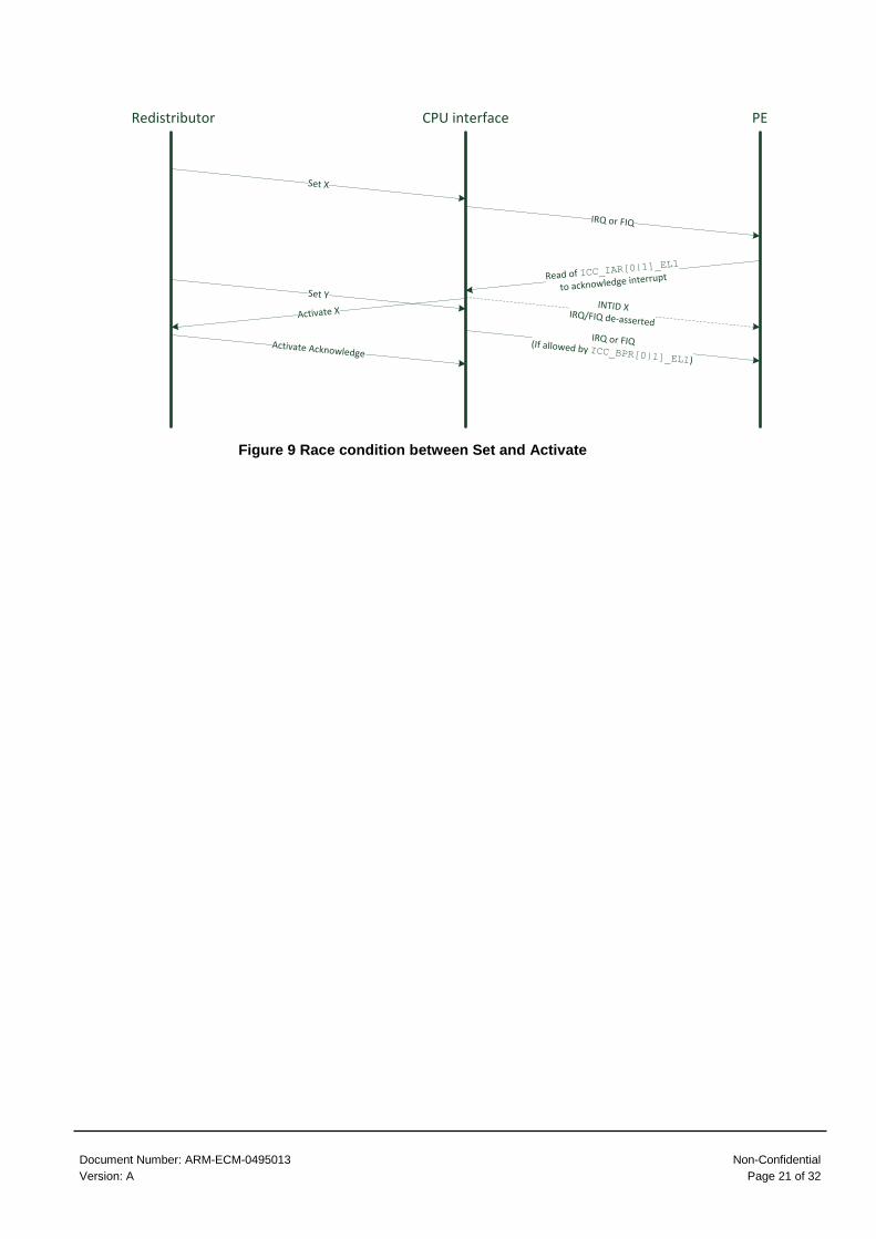
Figure 9 shows an example where the first interrupt is acknowledged before the second
Set command is received.
Document Number: ARM-ECM-0495013 Non-Confidential
Version: A Page 21 of 32
Redistributor CPU interface PE
Set X
IRQ or FIQ
Read of ICC_IAR[0|1]_EL
1
to acknowledge interrupt
Activate Acknowledge
INTID XIRQ/FIQ de-asserted
Activate X
Set Y
IRQ or FIQ(If allowed by ICC_BPR[0|1]_EL1)
Figure 9 Race condition between Set and Activate

Document Number: ARM-ECM-0495013 Non-Confidential
Version: A Page 22 of 32
4.5 SGI
SGIs are generated by software writing to one of three registers in the CPU interface.
The CPU interface issues a Generate SGI command, which includes the INTID, interrupt
group and target PE information.
The Redistributor issues a Generate SGI Acknowledge in response.
CPU interface PE
Write of ICC_SGI[0|1]R
_EL1
to generate a SGI
Generate SGI
Generate SGIAcknowledge
Redistributor
Figure 10 SGI generation

Document Number: ARM-ECM-0495013 Non-Confidential
Version: A Page 23 of 32
4.6 Clearing group enables in CPU interface
The CPU interface has individual enables for each interrupt group. The state of the group
enables is communicated to the Redistributor using the Upstream Control command.
If a Set command is received for an INTID belonging to an interrupt group that is disabled
in the CPU interface, it must be released. Similarly, if the interrupt group becomes
disabled then any outstanding Set command for an INTID belonging to that interrupt
group must be released.
Figure 11 shows an example of an interrupt being released in response to the interrupt
group becoming disabled.
Redistributor CPU interface PE
Set X
IRQ or FIQ
Write of ICC_IGRPEN[0|1]
_EL1
to clear Group enable
Release X
Upstream Control
communicating the clearing of the enable
Upstream ControlAcknowledge
IRQ/FIQ de-asserted
Figure 11 Clearing the Group enable(s) in the CPU interface
It is recommended, but not required, that the clearing of the group enable is
communicated before the Release command is sent. This ensures that the Redistributor
does not try to re-send the Set command for the same interrupt.
Note
The GIC Stream Protocol does not prohibit the Redistributor from sending a Set
command for an interrupt belonging to an interrupt group that is known to be disabled in
the CPU interface. However, this is expected to be a rare case because the CPU
interface would release the interrupt.

Document Number: ARM-ECM-0495013 Non-Confidential
Version: A Page 24 of 32
4.7 Power Management
The GICv3 specification provides a mechanism to quiesce the interface between a
Redistributor and a CPU interface.
The GIC_WAKER register contains two bits:
ProcessorSleep
Software writes this bit to 0 to bring up the interface, and writes 1 to bring the
interface down. This bit resets to 1.
ChildrenAsleep
This bit reports the state, up (0) or down (1), of the interface. After writing
ProcessorSleep, software polls ChildrenAsleep for the change to take
effect.
When the interface is down, no interrupts can be delivered to the CPU interface and
software must perform no actions that would result in traffic on the link, such as
attempting to deactivate previously acknowledged interrupts.
The GICv3 architecture states that behavior is UNPREDICTABLE if software writes to the
CPU interface registers while ChildrenAsleep==1 or ProcessorSleep==1.
Note
When GICR_WAKER.ProcessorSleep==1, interrupts targeting the PE generate wake –
up requests instead. This is outside of the scope of this document. For details refer to
the GICv3 Software Overview.
4.7.1 Power Up
When the interface is brought up (ProcesorSleep written from 1 to 0), the Redistributor
sends a Downstream Control command to the CPU interface. This informs the CPU
interface of the number of Security states supported and the supported INTID width.
The CPU interface replies with a Downstream Control Acknowledge. The Downstream
Control Acknowledge includes the smallest INTID width supported by the CPU interface
and the Redistributor. This ensures that the IRI does not attempt to send an interrupt with
a wider INTID than is supported by the CPU interface.

Document Number: ARM-ECM-0495013 Non-Confidential
Version: A Page 25 of 32
Redistributor CPU interface PE
Downstream Controlgiving DS and INTID width
GICR_WAKER.ChildrenAsleep==0
Downstream Control Acknowledge
giving INTID width
Write of GICR_WAKER
clearing the ProcessorSleep
Read of GICR_WAKER
Write of ICC_IGRPEN[0|1]
_EL1
to set Group enable(s)
Upstream Control
communicating the set of the enable(s)
Upstream ControlAcknowledge
GICR_WAKER.ChildrenAsleep==1
Read of GICR_WAKER
Software must poll GICR_WAKER.ChildrenAsleep until it reads 0. This bit will not read as 0 until after the
Downstream Write Acknowledge is received from the CPU Interface, but might take some time after that.
After waking it is likely that software will enable one or more Groups in the CPU Interface.
Figure 12 Power up sequence
After clearing ProcessorSleep to 0, software polls ChildrenAsleep until it reads 0.
ChildrenAsleep will not read as 0 until the Downstream Control has been sent and
acknowledged. As shown in Figure 12, ChildrenAsleep might not be updated
immediately.
4.7.2 Power Down
The interface is brought down by software writing ProcessorSleep to 1. The
Redistributor will issue a Quiesce command to the CPU interface.
The CPU interface must complete any outstanding traffic, and respond with a Queisce
Acknowledge.
When the Quiesce Acknowledge is received, the Redistributor can take down the
interface and update ChildrenAsleep.
Figure 13 shows a simple case where there are no outstanding actions for the CPU
interface.

Document Number: ARM-ECM-0495013 Non-Confidential
Version: A Page 26 of 32
Redistributor CPU interface PE
Quiesce
Quiesce
Acknowledge
Write of GICR_WAKER
setting the ProcessorSleep
After this point GICR_WAKER.ChildrenAsleep would read as 1, and no further interrupts can be
delivered to the PE
After this writing GICR_WAKER.ProcessorSleep to 1, software must not perform any actions which would
require additional communication on the link. For example, it must not Deactivate any previously
acknowledged interrupts.
Figure 13 Power down when outstanding interrupts or SGIs
Figure 14 shows a more complex example, where there is outstanding traffic when the
Quiesce command is received.
Redistributor CPU interface PE
Quiesce
Write of ICC_IGRPEN[0|
1]R_EL1
to disable interrupt groups
Upstream ControlAcknowledge
Quiesce
Acknowledge
Write of GICR_WAKER
setting the ProcessorSleep
After this point GICR_WAKER.ChildrenAsleep would read as 1, and no further interrupts can be
delivered to the PE
Upstream Control
CPU interface cannot send Quiesce Acknowledge until it has received the Upstream Control Acknowledge
Figure 14 Power down with outstanding traffic

Document Number: ARM-ECM-0495013 Non-Confidential
Version: A Page 27 of 32
5 GICv4: Directly Injected Virtual Interrupts
GICv4 adds the ability to directly inject virtual interrupts. This chapter describes the
additions to the GIC Stream Protocol to support this feature, and contains the following
sections:
Overview of GICv4 commands on page 28.
A typical virtual interrupt sequence on page 29.
De-asserted virtual interrupt on page 30.

Document Number: ARM-ECM-0495013 Non-Confidential
Version: A Page 28 of 32
5.1 Overview of GICv4 commands
GICv4 adds a number of additional commands to the GIC Stream Protocol.
Table 3 provides a summary of the additional commands a Redistributor issues to the
connected CPU interface.
Table 3 Commands issued by a Redistribuor to a CPU interface
Command Description
VSet X Sets the virtual interrupt with INTID X as pending on the CPU
interface.
VClear X Retrieves the virtual interrupt with INTID X from the CPU
interface
A number of CPU interface commands include a V field:
V==0: Specified INTID is physical.
V==1: Specified INTID is virtual.
For example, Release X:
V==0: Release the pending physical interrupt with INTID X.
V==1: Release the pending virtual interrupt with INTID X.
GICv4 allows only virtual LPIs to be directly injected. Therefore, the INTID for a VSet or
VClear command must always be 8192 or greater. Similarly, for any command with V==1
that includes an INTID, the INTID must be 8192 or greater.
Note
The command descriptions in this document are summaries. For a full description, and
encoding information, refer to the ARM® Generic Interrupt Controller Architecture
Specification GIC architecture version 3.0 and 4.0.

Document Number: ARM-ECM-0495013 Non-Confidential
Version: A Page 29 of 32
5.2 A typical virtual interrupt sequence
The process for sending virtual interrupts is the same as for physical interrupts other than
that a VSet command is used instead of Set.
Figure 15 shows a typical sequence of a virtual interrupt being sent, acknowledged and
deactivated.
Redistributor CPU interface PE
VSet X
vIRQ or vFIQ
Read of ICV_IAR[0|1]_EL
1
to acknowledge interrupt
Activate X
with V==1
Activate Acknowledgewith V==1
INTID XvIRQ/vFIQ de-asserted
Write of ICV_EOIR[0|1]_E
L1
Directly injected virtual interrupts can only be vLPIs. As vLPIs do not have an Active state, no
Deactivate is needed.
Figure 15 A virtual interrupt being sent and acknowledged
The Activate command is used by the CPU interface for both physical interrupts and
virtual interrupts. The V bit in the command reports the type of interrupt that is being
released.
No deactivate is needed for virtual interrupts. This is because GICv4 only allows virtual
LPIs to be directly injected, and LPIs do not have an Active state.

Document Number: ARM-ECM-0495013 Non-Confidential
Version: A Page 30 of 32
5.3 De-asserted virtual interrupt
The VClear command is used to retrieve a pending virtual interrupt from the CPU
Interface.
On receipt of the VClear the CPU interface must issue an Activate or Release for the
virtual interrupt, followed by a Clear Acknowledge.
Release and Clear Acknowledge are used for both physical interrupts and virtual
interrupts. As with the Activate command, these commands include a V field that reports
whether the interrupt is virtual or physical.
Figure 16 shows an example of the interrupt being released.
Redistributor CPU interface PE
VSet X
vIRQ or vFIQ
Release X
with V==1vIRQ/vFIQ de-asserted
VClear X
Clear Acknowledge
with V==1
Figure 16 A virtual interrupt being sent and then retrieved
As with physical interrupts, there is a possible race condition, where the virtual interrupt is
acknowledged before the VClear is received. In this case, an Activate is sent instead of a
Release. The CPU interface must wait for the Activate Acknowledge before sending the
Clear Acknowledge.
Redistributor CPU interface PE
VSet X
vIRQ or vFIQ
Read of ICV_IAR[0|1]_EL
1
to acknowledge virtual interrupt
Activate Acknowledgewith V==1
INTID XvIRQ/vFIQ de-asserted
Activate X
with V==1
VClear X
Clear Acknowledge
with V==1
The Redistributor does not need to wait for the Clear Acknowledge before sending the Activate Acknowledge.
Figure 17 Race between VClear and Activate commands

Document Number: ARM-ECM-0495013 Non-Confidential
Version: A Page 31 of 32
5.4 Interaction between physical interrupts and virtual interrupts
A CPU interface can host both a pending physical interrupt and a pending virtual interrupt
at the same time. Therefore a Set command will not displace a VSet, or vice versa.
Redistributor CPU interface PE
Set X
IRQ or FIQ
Read of ICC_IAR1_EL1
to acknowledge interrupt
Activate X
V==0
Activate Acknowledge
INTID XIRQ/FIQ de-asserted
VSet Y
Activate Acknowledge
vIRQ or vFIQ
Read of ICV_IAR[0|1]_EL
1
to acknowledge interrupt
Activate Y
V==1
INTID YvIRQ/vFIQ de-asserted
Write of ICC_DIR_EL1
to deactivate interrupt
(assumes EOImode==1)
Deactivate X
Write of ICV_EOIR[0|1]_E
L1
VSet does not displace Set
Directly injected virtual interrupts can only be vLPIs. As vLPIs do not have an Active
state, no Deactivate is needed.
Deactivate Acknowledge
Figure 18 VSet commands do not displace a pending physical interrupt
Figure 18 shows an example sequence, where a virtual interrupt and a physical interrupt
are pending on the CPU Interface at the same time. In the example, the physical interrupt
is activated first. This is typical because of the way the interrupt routing bits in the PE
must be set to allow virtual interrupts.
The example also shows the virtual interrupt being deactivated first. It would be equally
correct for the physical interrupt to be deactivated first. The order of deactivation
depends on the software running on the PE.

Document Number: ARM-ECM-0495013 Non-Confidential
Version: A Page 32 of 32
5.5 Mixing GICv3 and GICv4
The ARM® Generic Interrupt Controller Architecture Specification GIC architecture version
3.0 and 4.0 allows a system to include a mix of components that implement GICv3 and
GICv4.
5.5.1 GICv3 IRI and GICv4 CPU interface
In this arrangement the CPU interface supports the VSet and VClear commands, but the
connected Redistributor does not. This does not represent an integration problem.
5.5.2 GICv4 IRI and GICv3 CPU interface
The ARM® Generic Interrupt Controller Architecture Specification GIC architecture version
3.0 and 4.0 states that a Redistributor is not permitted to send VSet or VClear commands
to a CPU interface that does not implement GICv4.
The mechanism by which the Redistributor determines whether the CPU interface
implements GICv3 or GICv4 is IMPLEMENTATION DEFINED.
There are a number of possible approaches that could be taken, for example:
Design time tie off signals or synthesis options.
IMPLEMENTATION DEFINED registers in the IRI which are programmed during
system initialization.
o If the IRI supports two Security states, these would be Secure access
only registers.
IMPLEMENTATION DEFINED GIC Stream Protocol commands to allow reporting
of the architecture version.
o This requires that both the CPU interface and the Redistributor
understand the custom commands. This is typically only the case where
both logical components are from the same implementer.
Run-time detection.
o Only GICv4 CPU interfaces issue Upstream Command commands with
the identifier set to Virtual Group Enables. If the Redistributor receives
this command from the CPU interface it can infer that GICv4 is
supported.