ghp100xxxxs-d product datasheet - irf.com
TRANSCRIPT

HYBRID-HIGH RELIABILITY RADIATION HARDENED DC-DC CONVERTER
GHP
GHP-SERIES
Description
1 2021-08-30
PD-97897C
100V Input, Single/Dual Output
Applications Geostationary Earth Orbit Satellites (GEO)
Deep Space Satellites / Probes
Strategic Weapons and Communication System
International Rectifier HiRel Products, Inc.
Features Total Dose > 100 kRads(Si)
SEE Hardened to LET up to 82 MeV·cm2/mg
Low Weight < 110 grams
Low Input & Output Noise
Magnetically Coupled Feedback
65V to 110V DC Input Range
Up to 120W Output Power
Single and Dual Output Models Include 5, 12, 15 and ±12 and ±15V
High Efficiency to 87%
-55°C to +125°C Operating Temperature Range
100M @ 500VDC Isolation
Under-Voltage Lockout
Short Circuit and Overload Protection
Adjustable Output with an External Resistor
Remote Sense on Single Output Models
Synchronization Input and Output
External Inhibit
> 3.3 Million Hours MTBF

GHP-SERIES (100V Input, Single/Dual Output)
2 2021-08-30 International Rectifier HiRel Products, Inc.
Specifications
Absolute Maximum Ratings Recommended Operating Conditions
Input Voltage -0.5VDC to +120VDC Input Voltage +65VDC to +110VDC
Output power Internally limited Output power 0 to Max. Rated
Lead Temperature +300°C for 10 seconds Operating temperature -55°C to +85°C
Operating temperature -55°C to +125°C Operating temperature1 -55°C to +70°C
Storage temperature -55°C to +125°C
For Notes to Electrical Performance Characteristics, refer to page 5
1 For operation at +125°C, see table, note13
Electrical Performance Characteristics
Parameter Group A Subgroup
Conditions
-55°C TC +85°C VIN = 100V DC ± 5%, CL = 0 unless otherwise specified
Limits
Unit Min Nom Max
Input voltage (VIN) 65 100 110 V
Output voltage (VOUT) GHP10005S
GHP10012S GHP10015S GHP10012D GHP10015D
GHP10005S
GHP10012S GHP10015S GHP10012D GHP10015D
1 1 1 1 1
2,3 2,3 2,3 2,3 2,3
IOUT = 100% rated load Note 4
IOUT = 100% rated load Note 4
4.98 11.95 14.94 ±11.95 ±14.95
4.93 11.84 14.80 ±11.84 ±14.80
5.00 12.00 15.00 ±12.00 ±15.00
5.02 12.05 15.06 ±12.05 ±15.06
5.07 12.16 15.20 ±12.16 ±15.20
V
Output power (POUT) GHP10005S GHP10012S GHP10015S GHP10012D GHP10015D
1,2,3 VIN = 65, 100, 110 Volts, Note 2
0 0 0 0 0
100 120 120 100 100
W
Output current (IOUT) GHP10005S GHP10012S GHP10015S GHP10012D GHP10015D
1,2,3
VIN = 65, 100, 110 Volts, Note 2
Either Output, Note 3 Either Output, Note 3
0 0 0
1.6 1.3
20 10 8.0 6.67 5.3
A
Line regulation (VRLINE) 1,2,3 VIN = 65, 100, 110 Volts
IOUT = 0, 50%, 100% rated, Note 4
-10
10 mV
Load regulation (VRLOAD) 1,2,3 IOUT = 0, 50%, 100% rated, Note 4
VIN = 65, 100, 110 Volts
-0.5
0.5 %

GHP-SERIES (100V Input, Single/Dual Output)
3 2021-08-30 International Rectifier HiRel Products, Inc.
Electrical Performance Characteristics (continued)
Parameter Group A Subgroup
Conditions
-55°C TC +85°C VIN = 100V DC ± 5%, CL = 0 unless otherwise specified
Limits
Unit Min Nom Max
Cross regulation (VRCROSS) GHP10012D GHP10015D
1,2,3
Duals only, Note 5 VIN = 65, 100, 110 Volts
-3.0 -3.0
3.0 3.0
%
Total regulation (Line, Load, and Temperature)
1,2,3
VIN = 65, 100, 110 Volts IOUT = 0, 50%, 100% rated, Dual Model is measured
From +Output to –Output, Note 14
-2.0
2.0 %
Input current (IIN)
1,2,3
IOUT = 0, Pin 3 open, Note 14
Pin 3 shorted to Pin 2
70
2.5
100
5.0
mA
Output ripple (VRIP) GHP10005S GHP10012S GHP10015S GHP10012D GHP10015D
1,2,3
VIN = 65, 100, 110 Volts IOUT = 100% rated load
Notes 4, 6
15 25 25 20 20
50 60 60 60 60
mVp-p
Input ripple current 1,2,3 IOUT = 100% rated load 7.0 18 mArms
Switching frequency (FS) 1,2,3 Sync. Input (Pin 4) open 450 500 550 kHz
Efficiency (EFF) GHP10005S GHP10012S GHP10015S GHP10012D GHP10015D
1,2,3
IOUT = 100% rated load
Note 4
78 81 82 81 82
82 85 86 84 85
%
Inhibit Input Converter Off Sink current Converter On Sink current
1, 2, 3
Logic Low on Pin 3
Note 1 Logic High on Pin 3, Note 3
Note 1
-0.5
2.0
0.8 100 50 100
V
A V
A
For Notes to Electrical Performance Characteristics, refer to page 5

GHP-SERIES (100V Input, Single/Dual Output)
4 2021-08-30 International Rectifier HiRel Products, Inc.
Electrical Performance Characteristics (continued)
Parameter Group A Subgroup
Conditions
-55°C TC +85°C VIN = 100V DC ± 5%, CL = 0 unless otherwise specified
Limits
Unit
Min Nom Max
Synchronization Input frequency range pulse high level pulse low level pulse transition time pulse duty cycle
Ext. Clock on Sync. Input (Pin 4)
Note 1
450 4.0 -0.5 40 20
600 10 0.5
80
kHz V V
V/s %
Current Limit Point Expressed as a percentage of full rated load current
1,2,3
VOUT = 90% of Nominal, Note 4
145
%
Power dissipation, load fault (PD) 1,2,3 Short Circuit, Overload, Note 8 35 W
Output response to step load changes (VTLD) GHP10005S GHP10012S GHP10015S GHP10012D GHP10015D
4,5,6
Half Load to/from Full Load, Notes 4,9
-450 -600 -750 -750 -750
+450 +600 +750 +750 +750
mVpk
Recovery time, step load changes (TTLD)
4, 5, 6 Half Load to/from Full Load,
Notes 4, 9, 10 200 s
Output response to step line changes (VTLN)
65V to/from 110V
IOUT = 100% rated load, Notes 4,11 -150
150 mVpk
Recovery time, step line changes (TTLN)
65V to/from 110V
IOUT = 100% rated load, Notes 4,10,11
200 s
Capacitive load (CL) GHP10005S GHP10012S GHP10015S GHP10012D GHP10015D
IOUT = 100% rated load
No effect on DC performance Notes 1, 4, 7
Each output on duals
6000 1000 1000 500 500
µF
Turn-on Response Overshoot (VOS) Turn-on Delay (TDLY)
4,5,6
No Load, Full Load Notes 4,12
1.0
2.0 5.0
% ms
Line Rejection IOUT = 100% rated load
DC to 50 kHz, Notes 1, 4 40 60 dB
Isolation 1 Input to Output or Any Pin to Case
except Pin 6, test @ 500VDC 100 M
Device Weight 110 g
MTBF MIL-HDBK-217F2, SF, 35°C 3.3x10⁶ Hrs
For Notes to Electrical Performance Characteristics, refer to page 5

GHP-SERIES (100V Input, Single/Dual Output)
5 2021-08-30 International Rectifier HiRel Products, Inc.
Notes: Electrical Performance Characteristics Table 1. Parameter is tested as part of design characterization or after design changes. Thereafter, parameter shall be guaranteed to the
limits specified.
2. Parameter verified during line and load regulation tests.
3. Output load current must be distributed such that at least 20% of the total load current is being provided by one of the outputs.
4. Load current split equally between outputs on dual output models.
5. Cross regulation is measured with 20% rated load on output under test while changing the load on the other output from 20% to 80% of rated.
6. Guaranteed for a DC to 20MHz bandwidth. Tested using a 20kHz to 10MHz bandwidth.
7. Capacitive load may be any value from 0 to the maximum limit without compromising dc performance. A capacitive load in excess of the maximum limit may interfere with the proper operation of the converter’s overload protection, causing erratic behavior during turn-on.
8. Overload power dissipation is defined as the device power dissipation with the load set such that VOUT = 90% of nominal.
9. Load step transition time 10 s.
10. Recovery time is measured from the initiation of the transient to where VOUT has returned to within ±1% of its steady state value.
11. Line step transition time 100 s.
12. Turn-on delay time from either a step application of input power or a logic low to a logic high transition on the inhibit pin (pin 3) to the point where VOUT = 90% of nominal.
13. Although operation at temperatures between +85°C and +125°C is guaranteed, no parametric limits are specified.
14. The total regulation at EOL is ± 3% maximum.
Radiation Performance Characteristics
Test Conditions Min Typ Unit
Total Ionizing Dose (Gamma) MIL-STD-883, Method 1019
Operating bias applied during exposure Full Rated Load, VIN = 100V
100
150
kRads (Si)
Single Event Effects SEU, SEL, SEGR, SEB
Heavy ions (LET) Operating bias applied during exposure, Full Rated Load. VIN = 65V, 100V, 110V
Test Lab: Texas A & M University
82
MeV·cm2 /mg

GHP-SERIES (100V Input, Single/Dual Output)
6 2021-08-30 International Rectifier HiRel Products, Inc.
Fig 1. Block Diagram - Single Output
Fig 2. Block Diagram - Dual Output
1
3
2
7
10
INPUT
INHIBIT
RETURN
OUTPUT
RETURNBIAS
SUPPLY
UNDER VOLTAGE
LOCKOUT
& INHIBIT
EMIFILTER
PEAK
CURRENT
DETECTION
+12V
CASEGROUND
8 OUTPUT
9RETURN
13
11 -SENSEERROR
AMP
SENSE
AMPLIFIER
+SENSE6
REF &
S.S.
12ADJUST
+9V Sec. Bias
4SYNC.
INPUT
5SYNC.
OUTPUT
OSCILLATOR
PWMCONTROLLER SAMPLE
&
HOLD
FEEDBACK
TRIGGER
VFB
REFOUT
ILIM
S.S.CLK
FF
INPUT
OUTPUT
OUTPUT
OUTPUT
1
3
2
8
10
INPUT
INHIBIT
INPUT
RETURN
OUTPUT
RETURN
-OUTPUTBIAS
SUPPLY
UNDER VOLTAGE
LOCKOUT
& INHIBIT
EMI
FILTER
PEAK
CURRENT
DETECTION
+12V
CASEGROUND
6 +OUTPUT
11 -OUTPUT
13
ERROR
AMP
SENSE
AMPLIFIER
REF &
S.S.
12OUTPUT
ADJUST
+9V Sec. Bias
4SYNC.
INPUT
5SYNC.
OUTPUT
OSCILLATOR
PWM
CONTROLLER SAMPLE
&HOLD
FEEDBACK
TRIGGER
VFB
REFOUT
ILIM
S.S.CLK
FF
7
9
+OUTPUT
OUTPUT
RETURN

GHP-SERIES (100V Input, Single/Dual Output)
7 2021-08-30 International Rectifier HiRel Products, Inc.
Application Notes:
A) Attachment of the Converter
The following procedure is recommended for mounting the converter for optimum cooling and to circumvent any potential damage to the converter. Ensure that flatness of the plate where GHP converter to be mounted is no greater than 0.003” per linear inch. It is recommended that a thermally conductive gasket is used to promote the thermal transfer and to fill any voids existing between the two surfaces. HiRel recommends Sil-Pad 2000 with the thickness of 0.010".The shape of the gasket should match the footprint of the converter including the mounting flanges. The gasket is available from IR HiRel. The GHP-Series converter requires either M3 or 4-40 size screws for attachment purposes. The procedure for mounting the converter is as follows: 1. Check all mounting surfaces and remove foreign material, burrs, if any or anything that may interfere with the attachment of the converter. 2. Place the gasket on the surface reserved for the converter and line it up with the mounting holes. 3. Place the converter on the gasket and line both up with mounting holes. 4. Install screws using appropriate washers and tighten by hand (~ 4 in·oz) in the sequence shown below. 5. Tighten the screws with an appropriate torque driver. Torque the screws up to 6 in·lb in the sequence shown above.

GHP-SERIES (100V Input, Single/Dual Output)
8 2021-08-30 International Rectifier HiRel Products, Inc.
B) Output Voltage Adjustment.
Fig 3. Configuration for Adjusting Single Output Voltage
For all Single Output Models, to adjust the output voltages higher:
Where: RADJ is in kOhms
RADJ is connected to the -Out pin and VNOM < VOUT < 1.1VNOM (Fig. 3, Note 2)
VNOM is the nominal output voltage with the Adjust pin left open
VOUT is the desired output voltage
For all Single Output Models, to adjust the output voltages lower:
Where: RADJ is in kOhms
RADJ is connected to the +Out pin and 0.8VNOM < VOUT < VNOM (Fig. 3, Note 1)
VNOM is the nominal output voltage with the Adjust pin left open
VOUT is the desired output voltage
RADJ = 10 x (VNOM – 2.5)
- 50VOUT - VNOM
RADJ = 4 x (VNOM – 2.5) x ( VOUT – 2.5)
- 50VNOM - VOUT
Single Output:
To adjust the output voltage of the single output models, a resistor (RADJ) is connected between the Adjust pin (Pin 12)
and either the positive or negative remote sense pins, depending on whether the output voltage is to be adjusted higher
or lower than the nominal set-point. This allows the outputs to be reliably adjusted by approximately +10% to -20% of
the nominal output voltage. Refer to Fig. 3 and use equations provided to calculate the required resistance (RADJ).
Note: The output voltage adjust equation does not work as described for the 3.3V Single model. The adjust
range for 3.3V model is limited to 3.252V to 3.460V.
GHP-SERIES (100V Input, Single/Dual Output)
9 2021-08-30 International Rectifier HiRel Products, Inc.
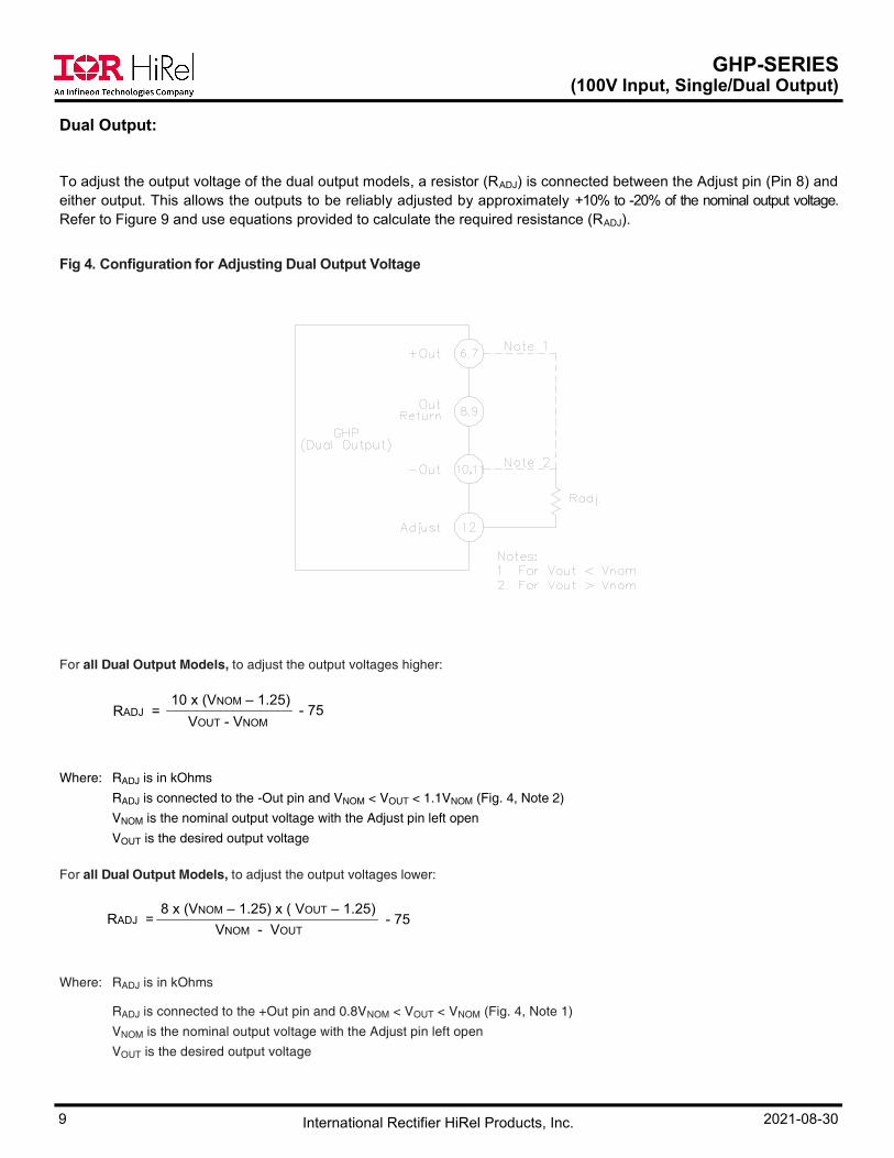
Dual Output:
To adjust the output voltage of the dual output models, a resistor (RADJ) is connected between the Adjust pin (Pin 8) and
either output. This allows the outputs to be reliably adjusted by approximately +10% to -20% of the nominal output voltage.
Refer to Figure 9 and use equations provided to calculate the required resistance (RADJ).
Fig 4. Configuration for Adjusting Dual Output Voltage
For all Dual Output Models, to adjust the output voltages higher:
Where: RADJ is in kOhms
RADJ is connected to the -Out pin and VNOM < VOUT < 1.1VNOM (Fig. 4, Note 2)
VNOM is the nominal output voltage with the Adjust pin left open
VOUT is the desired output voltage
For all Dual Output Models, to adjust the output voltages lower:
Where: RADJ is in kOhms
RADJ is connected to the +Out pin and 0.8VNOM < VOUT < VNOM (Fig. 4, Note 1)
VNOM is the nominal output voltage with the Adjust pin left open
VOUT is the desired output voltage
RADJ = 10 x (VNOM – 1.25)
- 75VOUT - VNOM
- 75RADJ = 8 x (VNOM – 1.25) x ( VOUT – 1.25)
VNOM - VOUT

GHP-SERIES (100V Input, Single/Dual Output)
10 2021-08-30 International Rectifier HiRel Products, Inc.
Pin Designation (Single/Dual)
Mechanical Outline
Single Output Dual Output
Pin # Designation Pin # Designation
1 Input 1 Input
2 Input Return 2 Input Return
3 Inhibit 3 Inhibit
4 Sync. Input 4 Sync. Input
5 Sync. Output 5 Sync. Output
6 + Sense 6 + Output
7 Output 7 + Output
8 Output 8 Output Return
9 Output Return 9 Output Return
10 Output Return 10 - Output
11 - Sense 11 - Output
12 Output Adjust 12 Output Adjust
13 Case Ground 13 Case Ground
3.055 MAX.
0.500 2.00
0.45 1.10
2.5002.30
0.200 Typ.
Non-
cum.
0.30
1.40 Ref.
3.50Ref.
0.475
MAX.
0.080Max.
0.260
PinØ0.040
R0.06254 places
0.50
0.60
0.20
Tolerance : .XX ±0.01
.XXX ±0.005
1
2
3
4
5
12
13
11
10
9
8
7
6
0.25
2.055
MAX.
FLANGE DETAIL
0.40
0.250.14
R0.0625

GHP-SERIES (100V Input, Single/Dual Output)
11 2021-08-30 International Rectifier HiRel Products, Inc.
Device Screening
Notes:
“EM” grade parts are strictly intended to permit the customer to determine the electrical functionality of the
device in the customer’s application in ambient conditions. The use of EM devices in production applications presents
an unquantifiable risk of failure and IR HiRel disclaims all responsibility for such failure.
"CK" grade is the flight model (FM) compliant to K Level screening as defined in the DLA Land and Maritime
MIL-PRF-38534 requirements, but is not necessarily a DLA Land and Maritime qualified SMD per MIL-PRF-38534.
The governing document for this part number designator is the IR HiRel datasheet (this document). Radiation rating
as stated in the “Radiation Performance Characteristics” section, is verified by analysis and test per IR HiRel internal
procedure. The part is marked with the IR base part number and the “CK” certification mark.
Part Number Designator /EM /CK
Compliance Level MIL-PRF-38534 — K level compliant
Certification Mark — CK
Screening Requirement MIL-STD-883 Method —
—
Temperature Range — Room Temperature -55°C to +85°C
Element Evaluation MIL-PRF-38534 N/A Class K
Non-Destructive Bond Pull 2023 N/A Yes
Internal Visual 2017 IR Defined Yes
Temperature Cycle 1010 N/A Cond C
Constant Acceleration 2001, Y1 Axis N/A 3000 Gs
PIND 2020 N/A Cond A
Burn-In 1015 N/A 320 hrs @ 125°C
(2 x 160 hrs)
Final Electrical
(Group A)
MIL-PRF-38534
& Specification Room Temperature
-55°C, +25°C,
+85°C
PDA MIL-PRF-38534 N/A 2%
Seal, Fine and Gross 1014 N/A Cond CH
Radiographic 2012 N/A Yes
External Visual 2009 IR Defined Yes

GHP-SERIES (100V Input, Single/Dual Output)
12 2021-08-30 International Rectifier HiRel Products, Inc.
Part Numbering
www.infineon.com/irhirel
Infineon Technologies Service Center: USA Tel: +1 (866) 951-9519 and International Tel: +49 89 234 65555
Leominster, Massachusetts 01453, USA Tel: +1 (978) 534-5776
San Jose, California 95134, USA Tel: +1 (408) 434-5000
Data and specifications subject to change without notice.
Output Voltage
05 = 5V
12 = 12V, 15 = 15V
Model
Nominal Input
Voltage
100 = 100V
Screening LevelEM, CKSee Devices Screening above
OutputS = Single
D = Dual
GHP 100 05 S /XX X
C = Gold Plated (/CK)A = Solder Dipped
Blank = Based on availability (EM)
Lead Finish
The DCDC converter models specified in this datasheet reflect the capability of the Series with at least one model
developed in full compliance to the MIL-PRF-38534 Class K SMD requirements including full design analyses
(electrical stress and thermal analysis, worst case analysis and FMEA), TID and SEE radiation testing and Group C
QCI. Model availability and model specific documentation availability depends on the model.
Any model listed in this datasheet and not previously manufactured can be developed on demand upon customer's
request by similarity using the same proven design rules, component and material type, production flow, production
processes and process control validated and qualified for the MIL-PRF-38534 Class K fully compliant models per IR
HiRel internal procedure. IR HiRel offer for similar device meets or exceeds MIL-PRF-38534 requirements for similar
device. Model specific QCI, design analyses and radiation testing are offered at customer's request.

GHP-SERIES (100V Input, Single/Dual Output)
13 2021-08-30 International Rectifier HiRel Products, Inc.
IMPORTANT NOTICE The information given in this document shall be in no event regarded as guarantee of conditions or characteristic. The data contained herein is a characterization of the component based on internal standards and is intended to demonstrate and provide guidance for typical part performance. It will require further evaluation, qualification and analysis to determine suitability in the application environment to confirm compliance to your system requirements. With respect to any example hints or any typical values stated herein and/or any information regarding the application of the product, Infineon Technologies hereby disclaims any and all warranties and liabilities of any kind including without limitation warranties on non- infringement of intellectual property rights and any third party. In addition, any information given in this document is subject to customer’s compliance with its obligations stated in this document and any applicable legal requirements, norms and standards concerning customer’s product and any use of the product of Infineon Technologies in customer’s applications. The data contained in this document is exclusively intended for technically trained staff. It is the responsibility of any customer’s technical departments to evaluate the suitability of the product for the intended applications and the completeness of the product information given in this document with respect to applications. For further information on the product, technology, delivery terms and conditions and prices, please contact your local
sales representative or go to (www.infineon.com/irhirel)
WARNING Due to technical requirements products may contain dangerous substances. For information on the types in question, please contact your nearest Infineon Technologies office.