gfr catalog
TRANSCRIPT

Product Catalogue andReference Manual
GFR Industries is WesternAustralia’s most experienced
and longest establishedfabricator, supply merchant,designer and installer of pe
and pe piping systems.
VERSION NO
2
GFR Company Profile
Preface
Section 1 PE Pressure Pipe Dimensions
Section 2 Flanged Systems, Fittings, Sheet & Rod
Section 3 Electrofusion Fittings
Section 4 Compression Fittings
Section 5 Backing Plates, Clamps, Joiners, Adaptorsand Repair Couplings
Section 6 Technical Information, SWJ Fittings, UPVCPressure Pipe & Fittings
Section 7 Valves
Section 8 Specialised Fabrications
Section 9 Special Application Pipes
Section 10 Conversion Charts & Chemical Resistance
Index
table of contents

Phone +61 8 250 2944 Fax +61 8 9250 2945 Freecall 1800 199 176 Email [email protected] www.gfr.com.au
GFR...your best choice.GFR is WA’s most experienced and longest established
fabricator, supply merchant, designer and installer of
pe and pe piping systems.
Track RecordNow into its third decade of business, GFR hasestablished itself as a reliable company with areputation for fair dealing and problem solving .
Innovation
The award of the Australian Design Mark in 2001 for theGFR Float Master valve was a ringing endorsement forGFR’s credentials as a serious player in valve design andmanufacture and also innovative use of engineeringplastics. GFR’s “Master” valves : Now has 2 US patentsgranted, an Australian Design Mark Award, andAustralian Patents, and other Patents pending.
Consultative
Our competent Staff Engineers and Sales Team ensurethat GFR’s products and services are tailored to the needsof every customer. Our high degree of flexibility,dedication to quality, innovation, and the personal pridetaken in everything we do enables GFR to deliversolutions where others cannot.

Phone +61 8 250 2944 Fax +61 8 9250 2945 Freecall 1800 199 176 Email [email protected] www.gfr.com.au
SupplyGFR has established terms of trade with all major manufacturers of pipeand fittings in both WA and the eastern states. This means the mostcompetitive pricing for you and, when combined with our in-housefabrication facility and stores inventory, means that GFR offers you thebest in-full / on-time service in WA.
FabricationQualified and skilled tradesmen using state-of-the-art equipment followdetailed quality and management guidelines to provide GFR Customerswith the very best quality fabrications. Extrusion welding to DVS 2207-4and butt fusion welding to ISO11414 ensures weld integrity.
GFR has Australias largest butt welder for plastic sheet. Welds up to 3metres wide and up to 50mm thick. This, when combined with GFR skill,equipment and quality components, provides your best solution.
GFR is an O.E.M. for some well known major Australian Companies.Please do not hesitate to ask for details.
DesignOur Design and Production Engineers, Project Managers, and Sales Staffprovide design and materials advice for poly applications in mining,industrial, utility, general water supply, and other handling applications.Specialised tank and vessel design using the new and unique “RITA”software is now available to GFR clients.
InstallationGFR has probably completed installations similar to a project that youmay be considering.
Explain your upcoming project to us and let us demonstrate our pastexperience with jobs similar to yours.
• Reticulation
• Heap leaches
• Borefield Installations
• Dam Liner Repairs and Installation
• Chemical Tank lining and Re-Lining
• Launder Chute Fabrication, Installation and Re-Lining
• PE, PP, PVC, ABS, PVDF, Installation carried out anywhere
• PE, PP, PVC, RCP Drainage and Associated Earthworks
• High Pressure Poly Lined Steel Pipelines
• Water Filtration, Aquaculture Tanks
• Large Bore Hobas Pipelines
• Tailings Lines and Dams
• Pontoons

Phone +61 8 250 2944 Fax +61 8 9250 2945 Freecall 1800 199 176 Email [email protected] www.gfr.com.au
PREFACEIt is intended that this manual will be re published in its present form from timeto time, so that it will continue to be fully relevant to modern industry practice.Any comments and suggestions regarding its content would be welcomed.
LIMITATION OF LIABILITYThe information, opinions, advice and recommendations contained in this publication are offered onlywith the object of providing a better understanding of technical matters associated with thefabrication, supply, design and installation of pe and pe piping systems and associated fittings.Readers should not act or rely upon any information contained in this publication without takingappropriate confirmational advice which relates to their particular circumstances
TERMS & CONDITIONS OF SALEGENERAL
These Conditions of Sale apply to all sales of products manufactured and or distributed by GFR. No variationor cancellation of any of these conditions of Sale should be binding on GFR unless agreed to by a responsibleofficer of GFR in writing.
PRICESPrices are subject to variation without notice. Products will be invoiced on the date of despatch at pricescurrent at that date.
PAYMENTStrictly net cash 30 days from end of month of supply, unless otherwise expressly arranged in writing.
GSTGST, where applicable, will be charged in accordance with current GST legislation.
CLAIM AND RETURNSGoods correctly delivered, as ordered, but wished to be returned, will incur a 20% restocking fee after priorapproval from GFR. All freight charges for returned goods will be at the customers expense.
WARRANTY“GFR guarantees its master valves for any defects in materials or manufacture for a period of one year fromthe original date of purchase, as long as the valves have been used under normal operating conditions. GFR’sliability under this warranty is limited to the replacement or repair of the defective valve. GFR does notaccept any consequential damages deriving from defects in the valve covered by this warranty. To the fullestextent the law permits, the warranty supersedes and voids all other warranties, whether expressed or implied(regardless of whether by agreement, conduct, statute or otherwise), including, without limitation, that ofmerchantability and fitness for particular purposes. No employee, representative or agent of GFR isauthorised to void, alter or add to the conditions contained in this warranty, nor to take responsibility for, normake guarantees not specified herein”In the case of goods not manufactured by GFR the manufacturer’s Condition of Sale will apply to those goodsand GFR will not be subject to any liability.
BACKORDERSBackorders will be held unless otherwise requested.
TITLE LIENa. As long as the Customer owes GFR any part of the price of goods supplied at any time, GFR shall retain the
legal title to all goods supplied and not yet used or resold in the ordinary course of business. When suchgoods are used, even with the loss of identity the legal title to the resultant product shall vest in GFR.Proceeds of sales of unused good of resultant products shall be received by the customer as agents of GFRand on their account such proceeds to be kept in a separate account or to be accounted for GFR on demand.
b. If goods are in the possession of a Customer to which title has not passed the Customer is under obligationto retain them in a good and merchantable condition and to ensure that they are stored separately andmarked as the property of GFR until they are either paid for or collected and to allow GFR for and/or itsservants or agents on to the premises where they are stored for the purpose of collecting the goods.
c. Goods supplied to a Customer shall be at the risk of the Customer from the time the goods ceased to bewithin the actual possession of GFR or its agents.
GFR acknowledges and thanks Vinidex and Iplex Pipelines for their respective inputs into this manual

SECTION 1PE Pressure Pipe Dimensions

Phone +61 8 250 2944 Fax +61 8 9250 2945 Freecall 1800 199 176 Email [email protected] www.gfr.com.au
1-1
Pres
sure
Pip
e D
imen
sion
s fo
r Wat
er &
Air
SDR
4133
2621
1713
.611
9PN
FO
R PE
803.
24
-6.
38
1012
.516
PN F
OR
PN10
04
-6.
38
1012
.516
20D
NM
IN.
MEA
NAV
E.M
IN.
MEA
NAV
E.M
IN.
MEA
NAV
E.M
IN.
MEA
NAV
E.M
IN.
MEA
NAV
E.M
IN.
MEA
NAV
E.M
IN.
MEA
NAV
E.M
IN.
MEA
NAV
E.W
ALL
IDM
ASS
WA
LLID
MA
SSW
ALL
IDM
ASS
WA
LLID
MA
SSW
ALL
IDM
ASS
WA
LLID
MA
SSW
ALL
IDM
ASS
WA
LLID
MA
SS16
1.6
12.7
0.07
51.
612
.70.
075
1.6
12.7
0.07
51.
612
.70.
075
1.6
12.7
0.07
51.
612
.70.
075
1.6
12.7
0.07
51.
812
.30.
082
201.
616
.70.
101.
616
.70.
101.
616
.70.
101.
616
.70.
101.
616
.70.
101.
616
.71.
001.
916
.10.
112.
315
.20.
1325
1.6
21.7
0.12
1.6
21.7
0.12
1.6
21.7
0.12
1.6
21.7
0.12
1.6
21.1
0.12
1.9
21.1
0.14
2.3
20.2
0.17
2.8
19.2
0.20
321.
628
.70.
161.
628
.70.
161.
628
.70.
161.
628
.70.
161.
928
.10.
182.
427
.00.
232.
926
.00.
273.
624
.50.
3240
1.6
36.7
0.20
1.6
36.7
0.20
1.6
36.7
0.20
1.9
36.1
0.23
2.4
35.0
0.29
3.0
33.8
0.25
3.7
32.3
0.42
4.5
30.6
0.50
501.
646
.70.
251.
646
.70.
252.
045
.90.
312.
445
.00.
373.
043
.80.
453.
742
.30.
544.
640
.40.
665.
638
.30.
7863
1.6
59.7
0.32
2.0
59.0
0.38
2.4
58.0
0.47
3.0
56.8
0.57
3.8
55.1
0.71
4.7
53.2
0.86
5.8
50.9
1.04
7.1
48.1
1.25
751.
671
.20.
452.
370
.30.
542.
969
.10.
673.
667
.60.
814.
565
.71.
005.
563
.61.
206.
860
.91.
458.
457
.51.
7590
2.2
85.5
0.63
2.8
84.3
0.78
3.5
85.2
0.97
4.3
81.1
1.17
5.4
78.8
1.44
6.6
76.3
1.73
8.2
72.9
2.10
10.1
68.6
2.55
110
2.7
104.
60.
923.
410
3.1
1.15
4.3
101.
21.
465.
399
.11.
756.
696
.42.
148.
193
.22.
5910
.089
.33.
1212
.384
.43.
7512
53.
111
8.9
1.20
3.9
117.
21.
494.
811
5.3
1.84
6.0
112.
82.
247.
410
9.8
2.74
9.2
106.
03.
3411
.410
1.4
1.05
14.0
96.0
4.84
140
3.5
133.
11.
584.
313
1.4
1.85
5.4
129.
12.
336.
712
6.4
2.81
8.3
123.
03.
4410
.311
8.8
4.19
12.7
113.
85.
0515
.710
7.5
6.08
160
4.0
152.
21.
974.
915
0.1
2.44
6.2
147.
53.
057.
714
4.4
3.68
9.5
140.
64.
4811
.813
5.8
5.47
14.6
129.
96.
6317
.912
3.0
7.92
180
4.4
171.
42.
455.
616
9.0
3.06
6.9
166.
23.
808.
616
2.6
4.63
10.7
158.
25.
6713
.315
2.7
6.94
16.4
146.
28.
3820
.113
8.4
10.0
220
04.
919
0.4
3.01
6.2
187.
73.
777.
718
4.5
4.71
9.6
180.
55.
7311
.917
5.7
7.00
14.7
169.
88.
5118
.216
2.4
10.3
322
.415
3.6
12.3
922
55.
521
4.2
3.38
6.9
211.
14.
798.
620
7.7
5.92
10.8
203.
17.
2413
.419
7.6
8.88
16.6
190.
910
.80
20.5
182.
713
.07
25.1
173.
015
.63
250
6.2
237.
84.
787.
723
4.6
5.90
9.6
230.
77.
3311
.922
5.9
8.87
14.8
219.
810
.88
18.4
212.
213
.31
22.7
203.
216
.08
27.9
192.
319
.27
280
6.9
266.
65.
928.
626
2.8
7.41
10.7
258.
69.
1513
.425
2.9
11.1
916
.624
6.2
13.6
720
.623
7.8
16.6
825
.422
7.7
20.1
631
.321
5.3
24.2
331
57.
730
0.0
7.44
9.7
295.
79.
3412
.129
0.7
11.6
615
.028
4.7
14.0
718
.727
6.9
17.3
123
.226
7.4
21.1
428
.625
6.1
25.5
235
.224
2.2
30.6
535
58.
733
8.1
9.46
10.9
333.
311
.85
13.6
327.
814
.73
16.9
320.
917
.86
21.1
312.
022
.03
26.1
301.
526
.80
32.2
288.
732
.39
39.6
273.
238
.84
400
9.8
380.
912
.00
12.3
375.
515
.02
15.3
369.
318
.68
19.1
361.
322
.77
23.7
351.
727
.84
29.4
339.
733
.98
36.3
325.
241
.12
44.7
307.
649
.37
450
11.0
458.
615
.13
13.8
422.
419
.04
17.2
415.
523
.61
21.5
406.
528
.80
26.7
395.
635
.27
33.1
382.
143
.05
40.9
365.
852
.08
50.3
346.
062
.51
500
12.3
476.
018
.82
15.3
496.
323
.52
19.1
461.
729
.13
23.9
451.
735
.53
29.6
439.
743
.45
36.8
424.
653
.12
45.4
406.
564
.26
55.8
384.
777
.03
560
13.7
533.
423
.45
17.2
525.
729
.49
21.4
517.
236
.51
26.7
506.
144
.47
33.2
492.
454
.60
41.2
475.
666
.64
50.8
455.
580
.50
630
15.4
600.
129
.67
19.3
591.
537
.26
24.1
581.
846
.27
30.0
569.
556
.17
37.2
554.
168
.99
46.3
535.
284
.23
57.2
512.
310
2.00
710
17.5
676.
337
.65
21.8
666.
647
.30
27.2
655.
658
.81
33.9
641.
671
.52
42.1
624.
387
.74
52.2
6.3.
110
7.01
800
19.6
761.
947
.87
24.5
751.
060
.09
30.6
738.
874
.48
38.1
723.
090
.65
47.7
703.
211
1.57
Not
e:1.
All d
imen
sion
s ar
e in
mill
imet
res
and
mas
s in
kg/
m.
2.N
omin
al D
iam
eter
(DN
) equ
als
outs
ide
diam
eter
.3.
Thes
e di
men
sion
s al
so a
pply
to T
HERM
APIP
E co
-ext
rude
d pi
pe4.
Thes
e di
men
sion
s ar
e ap
prox
imat
e as
allo
wed
for i
n th
e Au
stra
lian
Stan
dard

ASBESTOS CEMENT PIPE AS4139-1993
Nominal Size Outside Diameter in mm + .08 mm
58 77.680 95.6100 121.9150 177.3200 232.2225 259.1250 286.0
300 A 333.8300 B 333.8300 C 345.4300 D 345.4375 A 413.0375 B 413.0375 C 426.2450 A 492.2450 B 492.2450 C 507.0525 A 571.5525 B 571.5525 C 587.2600 A 650.2600 B 650.2600 C 667.0
PVC PRESSURE PIPE AS/NZS1477-1996 - SERIES 1
Nominal Size Outside Diametersin mm Min Max
15 21.2 21.520 26.6 26.925 33.4 33.732 42.1 42.440 48.1 48.450 60.2 60.565 75.2 75.580 88.7 89.1
100 114.1 114.5125 140.0 140.4150 160.0 160.5155 168.0 168.5175 200.0 200.5195 219.0 219.5200 225.0 225.6225 250.0 250.7250 280.0 280.8300 315.0 315.9350 355.0 356.0375 400.0 401.0400 450.0 451.0450 500.0 501.0500 560.0 561.0575 630.0 631.0
POLYETHYLENE PRESSURE PIPEAS/NZS4130-1997
Nominal Mean DiameterOutside OutsideDiameter in mm Minimum Maximum
50 50.0 50.463 63.0 63.575 75.0 75.690 90.0 90.8
110 110.0 110.9125 125.0 126.0140 140.0 141.2160 160.0 161.3180 180.0 181.5200 200.0 201.6225 225.0 226.8250 250.0 252.0280 280.0 282.3315 315.0 317.6355 355.0 357.9400 400.0 403.2450 450.0 453.6
PIPEDIMENSIONS
CAST IRON PRESSURE PIPE AS/NZS2544-1995
Nominal Size Outside Diameterin mm + 1.5mm
80 92.2100 121.9150 177.3200 232.2225 259.1250 286.0300 345.4375 426.2450 507.0500 560.3600 667.0
PVC (BLUE) PIPE AS/NZS1477-1996 Series 2COMPATIBLE WITH CAST
IRON PIPE AS/NZS2544-1995Outside Diameters Outside
Nominal DiameterSize in mm Min Max.
100 121.7 122.1150 177.1 177.6
COPPER TUBEAS1432-1996
Nominal Size Outside Diameterin mm Max.
6 6.358 7.94
10 9.5215 12.7018 15.8820 19.0525 25.4032 31.7540 38.1050 50.8065 63.5080 76.20100 101.60125 127.00150 152.40200 203.20
Phone +61 8 250 2944 Fax +61 8 9250 2945 Freecall 1800 199 176 Email [email protected] www.gfr.com.au
1-2

Phone +61 8 250 2944 Fax +61 8 9250 2945 Freecall 1800 199 176 Email [email protected] www.gfr.com.au
1-3
Pipe DimensionsPE Wall Thickness Comparison Guide
AS1159 TYPE 50 (HDPE) - AS4130 PE80(MDPE) / AS4130 PE100(HDPE)
16mm CLASS 3 CLASS 4.5 CLASS 6 CLASS 9 CLASS 12PN8 PN8 PN8 PN8 PN8
20mm CLASS 3 CLASS 4.5 CLASS 6 CLASS 9 CLASS 12PN8 PN8 PN8 PN8 PN16/20
25mm CLASS 3 CLASS 4.5 CLASS 6 CLASS 9 CLASS 12PN6.3/PN8 PN8/PN10 PN8/PN10 PN12.5/16 PN16
32mm CLASS 3 CLASS 4.5 CLASS 6 CLASS 9 CLASS 12PN4/- PN6.3/- PN8/PN10 PN12.5/16 PN16/20
40mm CLASS 3 CLASS 4.5 CLASS 6 CLASS 9 CLASS 12PN3.2 PN6.3/PN8 PN8/PN10 PN12.5/16 PN16/20
50mm CLASS 3 CLASS 4.5 CLASS 6 CLASS 9 CLASS 12PN4/- PN6.3/PN8 PN8/PN10 PN12.5/16 PN16/20
63mm CLASS 3 CLASS 4.5 CLASS 6 CLASS 9 CLASS 12PN4/- PN6.3/PN8 PN8/PN10 PN12.5/16 PN16/20
75mm CLASS 3 CLASS 4.5 CLASS 6 CLASS 9 CLASS 12PN4/- PN6.3/PN8 PN8/PN10 PN12.5/16 PN16/20
90mm CLASS 3 CLASS 4.5 CLASS 6 CLASS 9 CLASS 12PN4/- PN6.3/PN8 PN8/PN10 PN12.5/16 PN16/20
110mm CLASS 3 CLASS 4.5 CLASS 6 CLASS 9 CLASS 12PN4/- PN6.3/PN8 PN8/PN10 PN12.5/16 PN16/20
125mm CLASS 3 CLASS 4.5 CLASS 6 CLASS 9 CLASS 12PN4/- PN6.3/PN8 PN8/PN10 PN12.5/16 PN16/20
140mm CLASS 3 CLASS 4.5 CLASS 6 CLASS 9 CLASS 12PN4/- PN6.3/PN8 PN8/PN10 PN12.5/16 PN16/20
160mm CLASS 3 CLASS 4.5 CLASS 6 CLASS 9 CLASS 12PN4/- PN6.3/PN8 PN8/PN10 PN12.5/16 PN16/20
200mm CLASS 3 CLASS 4.5 CLASS 6 CLASS 9 CLASS 12PN4/- PN6.3/PN8 PN8/PN10 PN12.5/16 PN16/20
225mm CLASS 3 CLASS 4.5 CLASS 6 CLASS 9 CLASS 12PN4/- PN6.3/PN8 PN8/PN10 PN12.5/16 PN16/20
250mm CLASS 3 CLASS 4.5 CLASS 6 CLASS 9 CLASS 12PN4/- PN6.3/PN8 PN8/PN10 PN12.5/16 PN16/20
280mm CLASS 3 CLASS 4.5 CLASS 6 CLASS 9 CLASS 12PN4/- PN6.3/PN8 PN8/PN10 PN12.5/16 PN16/20
315mm CLASS 3 CLASS 4.5 CLASS 6 CLASS 9 CLASS 12PN4/- PN6.3/PN8 PN8/PN10 PN12.5/16 PN16/20
355mm CLASS 3 CLASS 4.5 CLASS 6 CLASS 9 CLASS 12PN4/- PN6.3/PN8 PN8/PN10 PN12.5/16 PN16/20
400mm CLASS 3 CLASS 4.5 CLASS 6 CLASS 9 CLASS 12PN4/- PN6.3/PN8 PN8/PN10 PN12.5/16 PN16/20
450mm CLASS 3 CLASS 4.5 CLASS 6 CLASS 9 CLASS 12PN4/- PN6.3/PN8 PN8/PN10 PN12.5/16 PN16/20
500mm CLASS 3 CLASS 4.5 CLASS 6 CLASS 9 CLASS 12PN4/- PN6.3/PN8 PN8/PN10 PN12.5/16
560mm CLASS 3 CLASS 4.5 CLASS 6 CLASS 9 CLASS 12PN4/- PN6.3/PN8 PN8/PN10 PN12.5/16
630mm CLASS 3 CLASS 4.5 CLASS 6 CLASS 9 CLASS 12PN4/- PN6.3/PN8 PN8/PN10
710mm CLASS 3 CLASS 4.5 CLASS 6 CLASS 9 CLASS 12PN4/- PN6.3/PN8 PN8/PN10
800mm CLASS 3 CLASS 4.5 CLASS 6 CLASS 9 CLASS 12PN4/- PN6.3/PN8
1000mm CLASS 3 CLASS 4.5 CLASS 6 CLASS 9 CLASS 12PN4/- PN6.3/PN8

Flanged Systems, Fittings, Sheet & Rod
SECTION 2

Short Radius Bends
Phone +61 8 250 2944 Fax +61 8 9250 2945 Freecall 1800 199 176 Email [email protected] www.gfr.com.au
2-1
90°DE R Z I20 20 25 525 25 30 532 32 37 540 40 45 550 50 58 863 63 71 875 75 85 1090 90 100 10110 110 120 10125 125 141 16140 140 158 18160 160 178 18180 180 199 19200 200 219 19225 225 242 17250 250 280 30280 280 320 40315 315 355 40355 355 380 25400 400 435 35
For dimension “S” refer to SDR sheet on page 1-1

Phone +61 8 250 2944 Fax +61 8 9250 2945 Freecall 1800 199 176 Email [email protected] www.gfr.com.au
2-2
* Radius may vary. Please specify if critical.Sizes above 400mm are readily available - please enquire.
For dimension “S” refer to SDR sheet on page 1-1.
Sweep Bends: extended for Electrofusion and Butt Welding
30° SWEEP BENDS 45° SWEEP BENDS
DE Z I R
63 140 75 22575 178 100 30590 178 100 305110 280 100 380125 330 150 375160 280 150 460200 343 200 535225 343 200 535250 420 250 615280 420 250 615315 445 250 715355 550 250 780400 750 250 1000
DE Z I R
63 175 75 22575 229 100 30590 229 100 305110 254 100 380125 304 150 380160 343 150 460200 420 200 535225 420 200 535250 507 250 615280 507 250 615315 558 250 715355 650 250 780400 800 250 1000

Phone +61 8 250 2944 Fax +61 8 9250 2945 Freecall 1800 199 176 Email [email protected] www.gfr.com.au
2-3Sweep Bends: extended for Electrofusion and Butt Welding
DE Z I R*
63 205 75 22575 280 100 30590 280 100 305110 318 100 380125 368 150 380160 420 150 460200 507 200 535225 507 200 535250 610 250 615280 610 250 615315 660 250 715355 740 250 780400 900 250 1000
DE Z I R*
63 300 75 22575 405 100 30590 405 100 305110 480 100 380125 530 150 380160 610 150 460200 735 200 535225 735 200 535250 865 250 615280 865 250 615315 965 250 715355 1130 250 780400 1250 250 1000
60° SWEEP BENDS 90° SWEEP BENDS
* Radius may vary. Please specify if critical.Sizes above 400mm are readily available - please enquire.
For dimension “S” refer to SDR sheet on page 1-1.
Phone +61 8 250 2944 Fax +61 8 9250 2945 Freecall 1800 199 176 Email [email protected] www.gfr.com.au
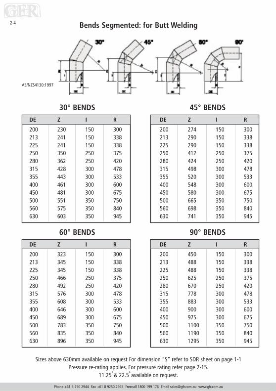
2-4 Bends Segmented: for Butt Welding
AS/NZS4130:1997
Sizes above 630mm available on request For dimension “S” refer to SDR sheet on page 1-1Pressure re-rating applies. For pressure rating refer page 2-15.
11.25o & 22.5
o available on request.
30° BENDSDE Z I R
200 230 150 300213 241 150 338225 241 150 338250 350 250 375280 362 250 420315 428 300 478355 443 300 533400 461 300 600450 481 300 675500 551 350 750560 575 350 840630 603 350 945
45° BENDSDE Z I R
200 274 150 300213 290 150 338225 290 150 338250 412 250 375280 424 250 420315 498 300 478355 520 300 533400 548 300 600450 580 300 675500 665 350 750560 698 350 840630 741 350 945
90° BENDSDE Z I R
200 450 150 300213 488 150 338225 488 150 338250 625 250 375280 670 250 420315 778 300 478355 883 300 533400 900 300 600450 975 300 675500 1100 350 750560 1190 350 840630 1295 350 945
60° BENDSDE Z I R
200 323 150 300213 345 150 338225 345 150 338250 466 250 375280 492 250 420315 576 300 478355 608 300 533400 646 300 600450 689 300 675500 783 350 750560 835 350 840630 896 350 945

Phone +61 8 250 2944 Fax +61 8 9250 2945 Freecall 1800 199 176 Email [email protected] www.gfr.com.au
2-5
DE L Z I
20 70 35 1425 78 40 1432 88 46 1640 90 50 1550 100 52 13.563 125 65 1575 147 75 1590 208 104 39110 248 120 50125 266 135 46140 293 145 48160 330 165 30200 385 190 55225 440 206 55250 465 232 70280 540 270 82315 530 268 75355 665 332 97400 682 337 100
Tees: Injection Moulded for Butt Welding
For long spigot moulded tees, please refer to electrofusion tables.For dimension “S” refer to SDR sheet on page 1-1.
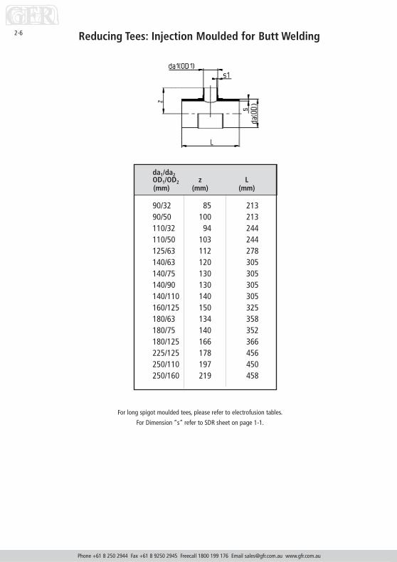
da1/da2OD1/OD2 z L(mm) (mm) (mm)
90/32 85 21390/50 100 213110/32 94 244110/50 103 244125/63 112 278140/63 120 305140/75 130 305140/90 130 305140/110 140 305160/125 150 325180/63 134 358180/75 140 352180/125 166 366225/125 178 456250/110 197 450250/160 219 458
Reducing Tees: Injection Moulded for Butt Welding
Phone +61 8 250 2944 Fax +61 8 9250 2945 Freecall 1800 199 176 Email [email protected] www.gfr.com.au
2-6
For long spigot moulded tees, please refer to electrofusion tables.
For Dimension “s” refer to SDR sheet on page 1-1.

Phone +61 8 250 2944 Fax +61 8 9250 2945 Freecall 1800 199 176 Email [email protected] www.gfr.com.au
2-7
DE1 DE2 L Z90 50 605 302.590 63 605 302.5110 50 635 317.5110 63 635 317.5110 75 635 317.5125 50 650 325125 63 650 325125 75 650 325125 90 650 325140 63 650 325140 75 650 325140 90 650 325140 110 650 325160 63 680 340160 75 680 340160 90 680 340160 110 680 340200 75 710 355200 90 710 355200 110 710 355200 125 710 355200 140 710 355200 160 710 355225 75 710 355225 90 710 355225 110 710 355225 140 710 355225 160 710 355250 90 740 355250 110 740 355250 125 740 355250 140 740 355250 160 740 355250 200 740 370280 110 740 370280 125 740 370280 140 740 370280 160 740 370280 200 740 370280 225 740 370315 110 760 380315 125 760 370315 140 760 370315 160 760 370315 200 760 370
DE1 DE2 L Z355 110 780 390355 125 780 390355 140 780 390355 160 780 390355 200 780 390355 225 780 390355 250 780 390355 280 780 390400 125 1120 560400 140 1120 560400 160 1120 560400 200 1120 560400 225 1120 560400 250 1120 560400 280 1120 560400 315 1120 560450 140 1145 572.5450 160 1145 572.5450 200 1145 572.5450 225 1145 572.5450 250 1145 572.5450 280 1145 572.5450 315 1145 572.5500 160 1170 585500 200 710 585500 225 710 585500 250 710 585500 280 710 585500 315 710 585500 355 710 585500 400 710 585560 200 1235 617.5560 225 1235 617.5560 250 1235 617.5560 280 1235 617.5560 315 1235 617.5560 355 1235 617.5560 400 1235 617.5630 200 1235 617.5630 225 1235 617.5630 250 1235 617.5630 280 1235 617.5630 315 1235 617.5630 355 1235 617.5
Reducing Tees: Fabricated for Butt WeldingDimensions in mm
Pressure re-rating applies, for pressure rating refer page 2-15.
Larger sizes available on request

Phone +61 8 250 2944 Fax +61 8 9250 2945 Freecall 1800 199 176 Email [email protected] www.gfr.com.au
2-8 Welded Tees: for Butt Welding
Larger sizes available on requestFor dimension “S” refer to SDR sheet on page 1-1.
Tees are available with fibreglass reinforcements. (Price on application)Pressure re-rating applies, for pressure rating refer page 2-15.
DE L Z
90 1210 605110 1270 635125 1270 650140 1300 650160 1360 680200 1420 710225 1420 710250 1480 740280 1480 740315 1520 760355 1560 780400 2240 1120450 2290 1145500 2340 1170560 2470 1235630 2470 1235
DE L Z
90 370 185110 450 225125 480 240140 480 240160 560 280200 620 310225 620 310250 680 340280 680 340315 760 380355 800 400400 960 480450 1010 505500 1060 530560 1190 595630 1190 595

Phone +61 8 250 2944 Fax +61 8 9250 2945 Freecall 1800 199 176 Email [email protected] www.gfr.com.au
2-9
DE L Z1 Z2 I1
90 700 275 425 150110 700 275 425 150125 745 290 455 150140 781 306 475 150160 842 330 512 150200 959 372 587 150225 1080 425 655 250250 1155 450 705 250280 1245 490 755 300315 1340 525 815 300355 1455 575 880 300400 1550 600 950 300450 1625 625 1000 300500 1700 650 1050 300
DE L1 L2
90 400 450110 400 450125 400 450140 400 600160 400 600200 400 750225 400 750250 400 900280 400 900315 400 1050355 500 1180400 500 1250450 600 1300500 600 1400560 800 1400630 800 1400
Junctions: Welded for Butt Welding
Dimensions in mm
Larger sizes available and Specific angles are available on request.Pressure re-rating applies, for pressure rating refer page 2-15.
45°/60° Junctions Y Sections
JUNCTIONS:45°/60° WELDED,FOR BUTTWELDING
Y-SECTIONS
AS/NZS4130:1997

Phone +61 8 250 2944 Fax +61 8 9250 2945 Freecall 1800 199 176 Email [email protected] www.gfr.com.au
2-10 Reducers: Concentric and Eccentric for Butt Welding
Dimension da(O.D.) da1 (O.D.1) Lmm mm mm
Other sizes and ratingsavailable to suit specific
requirements. P.O.A.AS4130:1997
25/2032/2032/2540/2040/2540/3250/2550/3250/4063/3263/4063/5075/3275/4075/5075/6390/5090/6390/75110/50110/63110/75110/90125/63125/75125/90125/110140/75140/90140/110140/125
25 2032 2032 2540 2040 2540 3250 2550 3250 4063 3263 4063 5075 3275 4075 5075 6390 5090 6390 75110 50110 63110 75110 90125 63125 75125 90125 110140 75140 90140 110140 125
36403945453849475056535978716163786768
10281948589
1038189
119110110
91
For dimension “S” refer to SDR sheet on page 1-1

Phone +61 8 250 2944 Fax +61 8 9250 2945 Freecall 1800 199 176 Email [email protected] www.gfr.com.au
2-11
Dimension da(O.D.) da1 (O.D.1) Lmm mm mm
160/90160/110160/125160/140180/90180/110180/125180/140180/160200/140200/160200/180225/140225/160225/180225/200250/160250/180250/200250/225280/200280/225280/250315/200315/225315/250315/280
160 90160 110160 125160 140180 90180 110180 125180 140180 160200 140200 160200 180225 140225 160225 180225 200250 160250 180250 200250 225280 200280 225280 250315 200315 225315 250315 280
109107113105157157115136122149134149135136167167151182149144206206165196203
186.5222
Reducers: Concentric and Eccentric for Butt Welding (cont.)
For dimension “S” refer to SDR sheet on page 1-1

Phone +61 8 250 2944 Fax +61 8 9250 2945 Freecall 1800 199 176 Email [email protected] www.gfr.com.au
2-12 Stub Flanges/Shouldered Ends for Butt Welding
Stub Flanges Shouldered Ends
DE D Z CouplingSize
63 68 65 23/8"75 97 75 31/2"90 97 75 31/2"110 122 75 41/2"125 176 75 61/2"140 176 75 61/2"160 176 75 61/2"200 235 75 85/8"225 235 75 85/8"250 287 75 103/4"280 338 75 123/4"315 338 75 123/4"355 369 75 14"
DE D1 Z H
63 96 50 1475 108 50 1490 128 60 14110 160 60 14125 192 65 25140 192 65 25160 213 65 25180 213 65 25200 270 75 25225 270 75 25250 334 80 30280 334 80 30315 380 80 30355 444 90 40400 495 90 40450 545 90 40500 602 105 50560 657 105 55630 708 110 55710 812 115 60800 948 115 601000 1136 115 60
For dimension “S” refer to SDR sheet on page 1-1
DIMENSIONS IN MM

Phone +61 8 250 2944 Fax +61 8 9250 2945 Freecall 1800 199 176 Email [email protected] www.gfr.com.au
2-13Flat Black HDPE Sheet
THICKNESS (mm) SHEET SIZE (m)
5 3 x 1.56 3 x 1.5
10 3 x 1.510 4 x 212 3 x 1.515 3 x 1.515 4 x 220 3 x 1.525 3 x 1.530 3 x 1.540 2 x 160 2 x 1
100 2 x 1
THICKNESS (mm) SHEET SIZE (m)
3 3 x 1.54.5 3 x 1.56 3 x 1.5
10 3 x 1.512 3 x 1.515 3 x 1.520 3 x 1.525 3 x 1.5
Flat Polypropylene Sheet

Polyethylene and Polypropylene Rod
Phone +61 8 250 2944 Fax +61 8 9250 2945 Freecall 1800 199 176 Email [email protected] www.gfr.com.au
2-14
Other colours and molecular weights available on request
Polypropylene Weld Rod
THICKNESS (mm) KG / REEL
3 2.24 2.2
3 core 2.2TRIANGLE 2.2
Polyethylene Weld Rod
THICKNESS (mm) KG / REEL
3 2.24 2.2
Polyethylene Solid Rod
THICKNESS (mm) LENGTH (m)
60 1110 1160 1
Polypropylene Solid Rod
THICKNESS (mm) LENGTH (m)
90 1125 1160 1

Phone +61 8 250 2944 Fax +61 8 9250 2945 Freecall 1800 199 176 Email [email protected] www.gfr.com.au
2-15
GFR FABRICATED FITTINGS ARE MANUFACTURED FROM PIPE OF THE PRESSURE DIMENSIONSHOWN IN THE CATALOGUE
These products should be pressure re-rated according to the following formulae.
BUTT WELDING1 All equal tees, junctions and mitre bends are to be fabricated by full face butt welding only.2 Fittings are to be hydrostatic pressure re-rated from the nominal pipe class. This re-rating takes
into account a butt weld strength of 90% of pipe strength, and stress increase due to fittingshape.
The re-rating factors to be applied are:-Rating = Pipe Class x 0.9
1.53 Wye (Y) junctions are for drainage applications only.4 All requirements for butt welding must be observed.
EXTRUSION WELDING1 Tees, junctions, and mitre bends may be extrusion welded where full face butt welding is not
available.2 Fittings made by extrusion welding are to be pressure re-rated from the nominal pipe class.
This re-rating takes into account an extrusion weld strength of 60% of pipe strength, and stressincrease due to fitting shape.
The re-rating factors to be applied are:-Rating = Pipe Class x 0.6
1.53 Wye (Y) junctions are for drainage applications only4 The maximum ratio of branch/main pipe diameters is 45%5 All requirements for extrusion welding must be observed.
Tees / Junctions / Mitre Bends
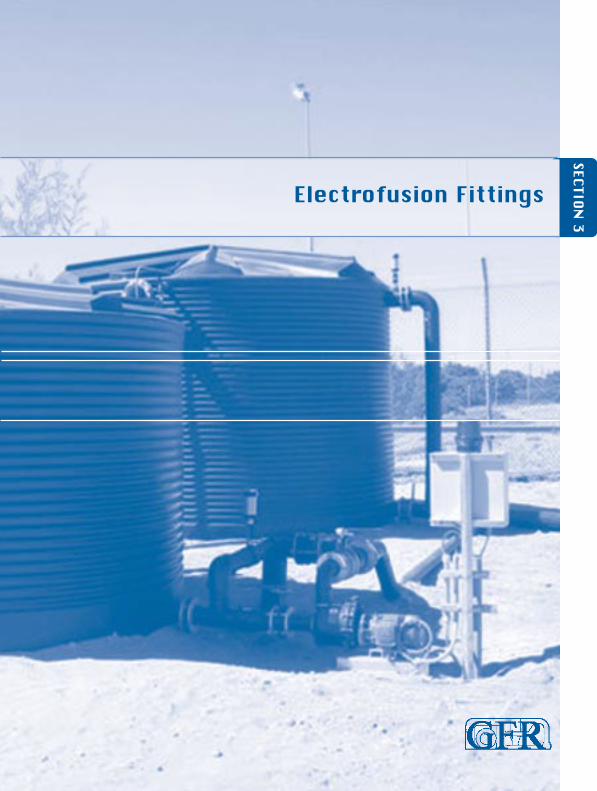
Electrofusion Fittings
SECTION 3

Coupling: Injection Moulded for Electrofusion
Phone +61 8 250 2944 Fax +61 8 9250 2945 Freecall 1800 199 176 Email [email protected] www.gfr.com.au
3-1
da 16 bar*OD t L d d1
(mm) (mm) (mm) (mm) (mm)
20 37.0 75 30 3425 40.0 81 35 3732 44.0 89 42 4040 49.0 99 53 4450 55.0 111 67 4963 63.0 127 83 5675 70.0 142 97 6390 70.0 142 115 74
110 74.5 152 140 83125 84.5 171 161 91140 89.5 181 180 99160 89.5 182 200 108180 99.0 201 221 119200 107.0 217 245 129225 114.0 231 275 145250 125.0 254 310 155280 112.0 225 365 183315 112.0 225 405 203
MOP water 16 / bar / gas 10 bar
Larger sizes available on request.

Stub Flanges: Extended for Electrofusion
Phone +61 8 250 2944 Fax +61 8 9250 2945 Freecall 1800 199 176 Email [email protected] www.gfr.com.au
3-2
daOD L d3 d4 h(mm) (mm) (mm) (mm) (mm)
20 88 27 45 725 88 33 58 932 89 40 68 1040 98 50 78 1150 101 61 88 1263 124 75 102 1475 126 89 122 1690 143 105 138 17
110 162 125 158 18125 170 132 158 25140 188 155 188 25160 181.5 175 212 25180 213 183 212 30200 181.5 232 268 32225 215 235 268 32250 275 285 320 35280 377 291 320 35315 382 335 370 35
Larger sizes available on request.

3-3Elbows: Injection moulded, extended for Electrofusion
Elbow 45° Elbow 90°
Larger sizes available on request
45° 90°
da(O.D.) z L3mm mm mm
20 44 3925 48 4232 57 4940 63 5350 70 5763 80 6475 90 7090 104 82110 108 82125 132.5 99.5140 135 100160 156.5 116.5180 176.5 131.5200 172 122225 182.5 125.5250 217 158280 238 173315 251 177
da(O.D.) z L3mm mm mm
20 68 5525 80 6332 71 5440 83 6050 91 6563 111 7775 128 8790 130 84110 149 91125 165.5 100140 183 105160 191 107.5180 225.5 120200 219.5 117.5225 238 121250 304 175280 340 197315 370 210
Phone +61 8 250 2944 Fax +61 8 9250 2945 Freecall 1800 199 176 Email [email protected] www.gfr.com.au

3-4 Caps: Injection moulded, extended for Electrofusion
da(O.D.) L L3mm mm mm
20 45 4025 48 4032 54 4540 61 5050 71 5763 84 6875 91 7590 107 84110 133 105125 132 100140 144 106160 167.5 123.5180 191.5 141.5200 181.5 127225 211.5 141.5250 230 152280 257 162315 262 167
Phone +61 8 250 2944 Fax +61 8 9250 2945 Freecall 1800 199 176 Email [email protected] www.gfr.com.au

3-5Adaptors: with male B.S.P thread extended for Electrofusion
DE G L I1 I2
20 1/2" 55 15 3025 3/4" 55 18 3025 1" 58 22 3032 1" 58 22 3040 11/4" 63 25 3050 11/2" 65 25 3263 2" 60 21 29
DE G L I1 I2
20 1/2" 55 15 3025 3/4" 55 18 3025 1" 58 22 3032 1" 58 22 3040 11/4" 63 25 3050 11/2" 65 25 3263 2" 60 21 29
Male Adaptors
Female Adaptors
Larger sizes available on request
Larger sizes available on request
Phone +61 8 250 2944 Fax +61 8 9250 2945 Freecall 1800 199 176 Email [email protected] www.gfr.com.au

3-6 Tees: Injection moulded, extended for Electrofusion
Specify required PN/SDR
Phone +61 8 250 2944 Fax +61 8 9250 2945 Freecall 1800 199 176 Email [email protected] www.gfr.com.au
da(O.D.) z L L3mm mm mm mm
20 54.5 107 3725 59 117 4032 71 144 4540 84 168 5150 95 189 5763 112 224 6375 128 260 7190 143 286 82110 158 317 86125 172 346 92.5140 190 380 98160 202.5 408 100180 260 521 138200 275 550 135225 271 548 146250 310 622 148280 347 694 160315 375 752 170
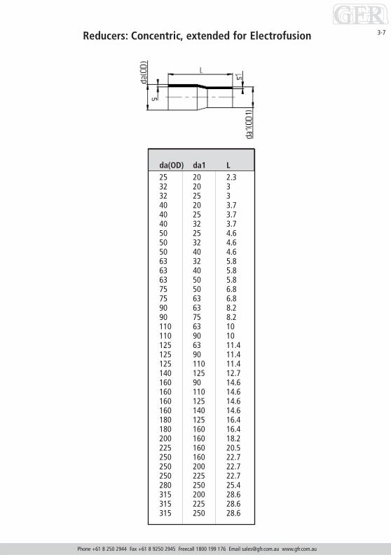
Reducers: Concentric, extended for Electrofusion
Phone +61 8 250 2944 Fax +61 8 9250 2945 Freecall 1800 199 176 Email [email protected] www.gfr.com.au
3-7
da(OD) da1 L25 20 2.332 20 332 25 340 20 3.740 25 3.740 32 3.750 25 4.650 32 4.650 40 4.663 32 5.863 40 5.863 50 5.875 50 6.875 63 6.890 63 8.290 75 8.2110 63 10110 90 10125 63 11.4125 90 11.4125 110 11.4140 125 12.7160 90 14.6160 110 14.6160 125 14.6160 140 14.6180 125 16.4180 160 16.4200 160 18.2225 160 20.5250 160 22.7250 200 22.7250 225 22.7280 250 25.4315 200 28.6315 225 28.6315 250 28.6

Compression Fittings
SECTION 4

Plasson Compression Fittings, Saddles and Valves
Phone +61 8 250 2944 Fax +61 8 9250 2945 Freecall 1800 199 176 Email [email protected] www.gfr.com.au
4-1
Plasson Compression Fittings, Saddles & Valves
MATERIALSCompression fittings, Tapping & Compression Saddles
BODY Polypropylene, high grade copolymer.NUT Polypropylene, high grade copolymer.SPLIT RING Acetal (POM) CPVC available.O-RING Nitrile rubber (NBR). EPDM and FRM O-rings available (Aprrox. 70 Shore A)REINFORCING RING Stainless steel on all female offtakes from 1 1/4” up to 4”
All Tapping Saddles have stainless steel reinforced female offtakes.NUT & BOLTS Galvanised steel (Stainless steel available).
Tapper® Saddles
BODY/COMPRESSION FITTING PolypropyleneBOLT AND NUT Stainless steel to SS316.CUTTER Brass to BS 2874-CZ122O-RING NBRSADDLE SEAL EPDMSPLIT RING Polyacetal
Valves
BODY Polypropylene, high grade copolymerO-RING NBR, EPDM or FRM O - depending on valve.SPRING (items 3067,3039) Stainless steel
Threaded Fittings Polypropylene. SS reinforced outlets are available
OPERATING PRESSURECompression fitting comply with requirements of AS/NZS 4129 (Int).StandardsMark license no. 2018Operating pressures at 20°C (water)PN16 Up to 63mm diameterPN12.5 75mm-125mm diameterPN10 160mm diameterAll female threads from 1 1/4” to 4” have stainless steel reinforcing rings and are Rated as above except that 4”is suitable for PN6.3 only.Plasson Tapping Saddles and Plasson Compression Saddles comply with specification 025 - ‘Tappings Bands’ ofAustralian Standards SAA MP52-1991.Tapper®WIS 4-22-02/WRC Standards-PN16. WSA approved.Plasson polypropylene BSP threaded fittings: 1.0 Mpa for male fittings, 0.6 MpaFor female fittings (1.0 Mpa for SS reinforced female fittings).Plasson polypropylene valves: PN10 or PN12.5
PIPE SUITABILITYPlasson Compression Fittings : for pipes 16mm to 160mm outside diamter.Metric OD System for use with polyethylene pipe manufactured to:
• AS1159-1988-Polyethylene Pipes for Pressure Applications• AS4130 (Int)-PE Pipes for Pressure Applications• PE Pipes with outside dimensions to ISO OD series system.
Plasson Rural Fittings: for Type 50 Class rural Polyethylene Pipe manufactured to:• AS 2698.2 (ID Series)-Class 6
Plasson Compression Fittings, Saddles and Valves
Phone +61 8 250 2944 Fax +61 8 9250 2945 Freecall 1800 199 176 Email [email protected] www.gfr.com.au
4-2
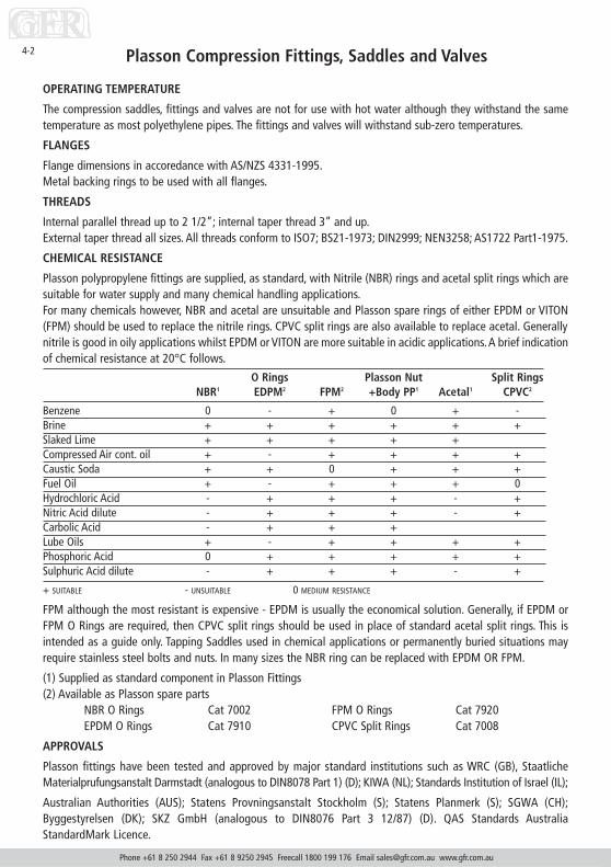
OPERATING TEMPERATURE
The compression saddles, fittings and valves are not for use with hot water although they withstand the sametemperature as most polyethylene pipes. The fittings and valves will withstand sub-zero temperatures.
FLANGES
Flange dimensions in accoredance with AS/NZS 4331-1995.Metal backing rings to be used with all flanges.
THREADS
Internal parallel thread up to 2 1/2”; internal taper thread 3” and up.External taper thread all sizes. All threads conform to ISO7; BS21-1973; DIN2999; NEN3258; AS1722 Part1-1975.
CHEMICAL RESISTANCE
Plasson polypropylene fittings are supplied, as standard, with Nitrile (NBR) rings and acetal split rings which aresuitable for water supply and many chemical handling applications.For many chemicals however, NBR and acetal are unsuitable and Plasson spare rings of either EPDM or VITON(FPM) should be used to replace the nitrile rings. CPVC split rings are also available to replace acetal. Generallynitrile is good in oily applications whilst EPDM or VITON are more suitable in acidic applications.A brief indicationof chemical resistance at 20°C follows.
O Rings Plasson Nut Split RingsNBR1 EDPM2 FPM2 +Body PP1 Acetal1 CPVC2
Benzene 0 - + 0 + -Brine + + + + + +Slaked Lime + + + + +Compressed Air cont. oil + - + + + +Caustic Soda + + 0 + + +Fuel Oil + - + + + 0Hydrochloric Acid - + + + - +Nitric Acid dilute - + + + - +Carbolic Acid - + + +Lube Oils + - + + + +Phosphoric Acid 0 + + + + +Sulphuric Acid dilute - + + + - +
+ SUITABLE - UNSUITABLE 0 MEDIUM RESISTANCE
FPM although the most resistant is expensive - EPDM is usually the economical solution. Generally, if EPDM orFPM O Rings are required, then CPVC split rings should be used in place of standard acetal split rings. This isintended as a guide only. Tapping Saddles used in chemical applications or permanently buried situations mayrequire stainless steel bolts and nuts. In many sizes the NBR ring can be replaced with EPDM OR FPM.
(1) Supplied as standard component in Plasson Fittings(2) Available as Plasson spare parts
NBR O Rings Cat 7002 FPM O Rings Cat 7920EPDM O Rings Cat 7910 CPVC Split Rings Cat 7008
APPROVALS
Plasson fittings have been tested and approved by major standard institutions such as WRC (GB), StaatlicheMaterialprufungsanstalt Darmstadt (analogous to DIN8078 Part 1) (D); KIWA (NL); Standards Institution of Israel (IL);
Australian Authorities (AUS); Statens Provningsanstalt Stockholm (S); Statens Planmerk (S); SGWA (CH);Byggestyrelsen (DK); SKZ GmbH (analogous to DIN8076 Part 3 12/87) (D). QAS Standards AustraliaStandardMark Licence.

Compression Fittings
Phone +61 8 250 2944 Fax +61 8 9250 2945 Freecall 1800 199 176 Email [email protected] www.gfr.com.au
4-3
CompressionCouplings
16-1620-2025-2532-3240-4050-5063-6375-7590-90
110-110125-125
*160-160
Reducing Couplings20-1625-1625-2032-2032-2540-2540-3250-2550-3250-4063-2563-3263-4063-5075-5075-6390-6390-75110-90
Repair Couplings20-2025-2532-3240-4050-5063-6375-7590-90
110-110125- 125
*supplied with 4 x 165mm x m16mild steel hex head galvanised bolts

Compression Fittings
Phone +61 8 250 2944 Fax +61 8 9250 2945 Freecall 1800 199 176 Email [email protected] www.gfr.com.au
4-4
90 DegReducing Tee
1 2 320 x 20 x 1625 x 25 x 2032 x 32 x 2540 x 40 x 2540 x 40 x 3250 x 50 x 2550 x 50 x 3250 x 50 x 4063 x 63 x 3263 x 63 x 4063 x 63 x 5075 x 75 x 63
90 Deg TeeWith ThreadedMale Offtake
1 2 320 x 20 x 1/2”20 x 20 x 3/4”25 x 25 x 1/2”25 x 25 x 3/4”32 x 32 x 1”40 x 40 x 11/4”40 x 40 x 11/2”50 x 50 x 11/4”50 x 50 x 11/2”63 x 63 x 11/4”63 x 63 x 11/2”63 x 63 x 2”
90 Deg Tee162025324050637590
110160
1 = Main 2 = Main 3 = Offtake
1 = Main 2 = Main 3 = Offtake

Compression Fittings
Phone +61 8 250 2944 Fax +61 8 9250 2945 Freecall 1800 199 176 Email [email protected] www.gfr.com.au
4-5
90 Deg Reducing TeeWith Threaded Female Offtake
1 2 320 x 16 x 3/4”25 x 20 x 3/4”32 x 25 x 1”
90 Deg Tee With Threaded Female Offtake
1 2 316 x 16 x 1/2”16 x 16 x 3/4”20 x 20 x 1/2”20 x 20 x 3/4”25 x 25 x 1/2”25 x 25 x 3/4”25 x 25 x 1”
*25 x 25 x 11/4”32 x 32 x 3/4”32 x 32 x 1”
*32 x 32 x 11/4”*32 x 32 x 11/2”40 x 40 x 1”
*40 x 40 x 11/4”*40 x 40 x 11/2”*40 x 40 x 2”*50 x 50 x 11/2”*50 x 50 x 2”*63 x 63 x 11/4”*63 x 63 x 11/2”*63 x 63 x 2”*75 x 75 x 2”*75 x 75 x 21/2”*75 x 75 x 3”*90 x 90 x 3”+*110 x 110 x 4”
1 = Main 2 = Main 3 = Offtake
* With stainless steel reinforcing ring+ Available PN 6.3 only
1 = Main 2 = Main 3 = Offtake
Compression Fittings
Phone +61 8 250 2944 Fax +61 8 9250 2945 Freecall 1800 199 176 Email [email protected] www.gfr.com.au
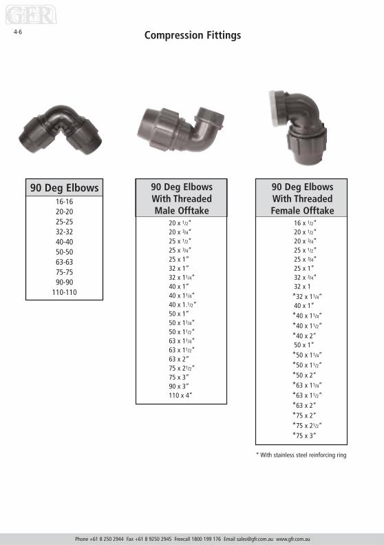
4-6
90 Deg ElbowsWith Threaded Female Offtake
16 x 1/2”20 x 1/2”20 x 3/4”25 x 1/2”25 x 3/4”25 x 1”32 x 3/4”32 x 1*32 x 11/4”40 x 1”*40 x 11/4”*40 x 11/2”*40 x 2”50 x 1”*50 x 11/4”*50 x 11/2”*50 x 2”*63 x 11/4”*63 x 11/2”*63 x 2”*75 x 2”*75 x 21/2”*75 x 3”
90 Deg ElbowsWith Threaded Male Offtake
20 x 1/2”20 x 3/4”25 x 1/2”25 x 3/4”25 x 1”32 x 1”32 x 11/4”40 x 1”40 x 11/4”40 x 1.1/2”50 x 1”50 x 11/4”50 x 11/2”63 x 11/4”63 x 11/2”63 x 2”75 x 21/2”75 x 3”90 x 3”110 x 4”
90 Deg Elbows16-1620-2025-2532-3240-4050-5063-6375-7590-90
110-110
* With stainless steel reinforcing ring

Compression Fittings
Phone +61 8 250 2944 Fax +61 8 9250 2945 Freecall 1800 199 176 Email [email protected] www.gfr.com.au
4-7
45 Deg Elbow40-4050-5063-6390-90
110-110
Male Adaptor16 x 1/2”16 x 3/4”20 x 1/2”20 x 3/4”20 x 1”25 x 1/2”25 x 3/4”25 x 1”32 x 3/4”32 x 1”32 x 11/4”32 x 11/2”40 x 1”40 x 11/4”40 x 11/2”40 x 2”50 x 1”50 x 11/4”50 x 11/2”50 x 2”63 x 11/4”63 x 11/2”63 x 2”63 x 21/2”75 x 2”75 x 21/2”75 x 3”90 x 2”90 x 21/2”90 x 3”90 x 4”110 x 2”110 x 3”110 x 4”
45 Deg Elbow with Threaded Male Offtake
20 x 1/2”20 x 3/4”

Compression Fittings
Phone +61 8 250 2944 Fax +61 8 9250 2945 Freecall 1800 199 176 Email [email protected] www.gfr.com.au
4-8
Female Adaptor16 x 1/2”16 x 3/4”20 x 1/2”20 x 3/4”20 x 1”25 x 3/4”25 x 1”32 x 3/4”32 x 1”
*32 x 11/4”*40 x 1”*40 x 11/4”*40 x 11/2”*50 x 11/4”*50 x 11/2”*50 x 2”*63 x 11/4”*63 x 11/2”*63 x 2”*75 x 2”*75 x 21/2”*90 x 2”*90 x 3”+*90 x 4”*110 x 3”+*110 x 4”
Flanged Coupling with Metal Flange
AS2129/AS4987 AS/NZS4331:199850 x 2” 1 50 x (40) 11/2” I.S.O50 x 21/2” 1 50 x (50) 2” I.S.O63 x 21/2” 1 63 x (50) 2” I.S.O75 x 3” 1 75 x (63) 21/2” I.S.O90 x 4” 1 90 x (100) 4” I.S.O110 x 4” 1 110 x (100) 4” I.S.O125 x 5” 1 125 x (125) 5” I.S.O125 x 6” 1 125 x (150) 6” I.S.O160 x 5” 1 125/160 x (125) 5” I.S.O160 x 6” 1 125/160 x (150) 6” I.S.O
* With stainless steel reinforcing ring+ Available PN6.3 only
Use M16 bolts with 6” flanges

Compression Fittings
Phone +61 8 250 2944 Fax +61 8 9250 2945 Freecall 1800 199 176 Email [email protected] www.gfr.com.au
4-9
End Plug2025324050637590
110
O-Ring Viton+**
162025324050637590
110
O-Ring EPDM+*
162025324050637590
110
O-Ring Nitrile162025324050637590
110125160
* Blue Mark - a better chemical resistance than NBR** White Mark - a better chemical resistance than NBR
+ When these rings are used the use of CPVC split rings will usually be required

Compression Fittings
Phone +61 8 250 2944 Fax +61 8 9250 2945 Freecall 1800 199 176 Email [email protected] www.gfr.com.au
4-10
*Split Ring Acetal162025324050637590
110125
Insert PP7590
110125U125L
**Split Ring C-PVC162025324050637590110
* Standard split ring supplied with fittings** Used in place of accetal in acid or agressive chemical environments - yellow / brown colour

GAL
V* Z
inc
plat
ed w
ith C
hrom
ate
pass
ivat
or -
Yello
w c
olou
r (sh
iny)
.
Single Tapping Saddle
Phone +61 8 250 2944 Fax +61 8 9250 2945 Freecall 1800 199 176 Email [email protected] www.gfr.com.au
4-11
Tapping Saddle for Rural & Metric withS/Steel Reinforcing Ring & Galv.* Bolts 20-5020 x 1/2” Metric & Rural (Long Bolts) PEFI25 x 1/2” Metric & Rural (Long Bolts) PEFI25 x 3/4” Metric & Rural (Long Bolts) PEFI32 x 1/2” Metric & Rural (Long Bolts) PEFI32 x 3/4” Metric & Rural (Long Bolts) PEFI32 x 1” Metric & Rural (Long Bolts) PEFI40 x 1/2” Metric & Rural (Long Bolts) PEFI40 x 3/4” Metric & Rural (Long Bolts) PEFI40 x 1” Metric & Rural (Long Bolts) PEFI50 x 1/2” Metric & Rural (Long Bolts) PEFI50 x 3/4” Rural only PEFI50 x 1” Rural only PEFI50 x 11/4” Metric & Rural (Long Bolts) PEFI
2 BOLTS
Tapping Saddle for Metric with S/SteelReinforcing Ring & Galv.* Bolts 50 - 180
For Metric Pipe50 x 3/4” PEFI50 x 1” 2 BOLTS PEFI50 x 11/4” PEFI63 x 1/2” PEFI63 x 3/4” PEFI63 x 1” PEFI63 x 11/4” PEFI63 x 11/2” PEFI75 x 1/2” PEFI75 x 3/4” PEFI75 x 1” PEFI75 x 11/4” PEFI75 x 11/2” PEFI75 x 2” PEFI90 x 1/2” 4 BOLTS PEFI90 x 3/4” PEFI90 x 1” PEFI90 x 11/4” PEFI90 x 11/2” PEFI90 x 2” PEFI110 x 1/2” PEFI110 x 3/4” PEFI110 x 1” PEFI110 x 11/4” PEFI110 x 11/2” PEFI110 x 2” PEFI125 x 3/4” PEFI125 x 1” PEFI125 x 11/4” PEFI125 x 11/2” PEFI125 x 2” PEFI140 x 1” PEFI140 x 11/4” PEFI140 x 11/2” PEFI140 x 2” 6 BOLTS PEFI160 x 1” PEFI160 x 11/4” PEFI160 x 11/2” PEFI160 x 2” PEFI180 x 1” PEFI180 x 11/4” PEFI180 x 11/2” PEFI180 x 2” PEFI
The
nuts
and
bol
ts a
re m
ade
of g
alva
nise
d st
eel.
O-R
ings
are
NBR
rubb
er.F
PM a
nd E
PDM
O-R
ings
are
ava
ilabl
e su
bjec
tto
spe
cial
pric
ing
and
deliv
ery.
GAL
V*Zi
nc p
late
d w
ith C
hrom
ate
pass
ivat
or -
Yello
w c
olou
r (sh
iny)
.S/
S N
uts
- Bol
ts a
vaila
ble
on re
ques
t.La
rger
siz
es a
vaila
ble
on re
ques
t.

SocketsSIZE
FEMALE - FEMALE
1/2"3/4" x 1/2"
3/4"1" x 1/2"1 x 3/4"
1”11/4" x 3/4"11/4 x 1”"
11/4"11/2" x 3/4"11/2 x 1”"
11/2" x 11/4"11/2"
2" x 1/2"2” x 3/4”2” x 1”
2” x 11/4”2” x 11/2”
2”
Threaded Fittings
Phone +61 8 250 2944 Fax +61 8 9250 2945 Freecall 1800 199 176 Email [email protected] www.gfr.com.au
4-12
ElbowsSIZE
FEMALE - FEMALE
1/2"3/4"1"2"
MALE - FEMALE
1/2"3/4"1"
11/4”11/2”2”
TeesSIZE
FEMALE - FEMALE
1/2"3/4"1"2"

Threaded Fittings
Phone +61 8 250 2944 Fax +61 8 9250 2945 Freecall 1800 199 176 Email [email protected] www.gfr.com.au
4-13
Reducing BushesSIZE
MALE - FEMALE3/4" x 1/2"1" x 1/2"1" x 3/4"
11/4" x 1/2"11/4" x 3/4"11/4" x 1"11/2" x 1/2"11/2" x 3/4"11/2" x 1"
11/2" x 11/4"2" x 1/2"2" x 3/4"2" x 1"
2" x 11/4"2" x 11/2"3” x 2”
3” x 21/2"4” x 2”4” x 3”
Plugs - ThreadedSIZE1/2"3/4"
1"11/4"11/2"2"
NipplesSIZE1/2"
3/4 x 1/2"3/4"
1" x 1/2"1" x 3/4"
1"1.1/4” x 1/2"1.1/4" x 3/4"11/4" x 1"11/4" x 1"
11/4"11/2" x 1/2"11/2" x 3/4"11/2" x 1"
11/2" x 11/4"11/2”
2” x 1/2”"2" x 3/4"2" x 1"
2" x 11/4"2" x 11/2"
2"21/2”
3” x 2”3” x 21/2”
3”4” x 3”
4”
Caps1/2"3/4"1”11/4"11/2"2”

Backing Plates
SECTION 5

Backing Plate (BUP) Table D
Phone +61 8 250 2944 Fax +61 8 9250 2945 Freecall 1800 199 176 Email [email protected] www.gfr.com.au
5-1
STEEL POLY I.D. O.D. PCD HOLES x DIA THICKFLANGE SIZE NESS
SIZE
20 25 36 101 74 4 x 14 1025 32 44 115 83 4 x 14 1032 40 52 120 87 4 x 14 1040 50 62 135 98 4 x 14 1050 63 74 150 114 4 x 18 1065 75 87 165 127 4 x 18 1080 90 103 185 146 4 x 18 11100 110 125 215 178 4 x 18 11125 125 155 255 210 8 x 18 13125 140 155 255 210 8 x 18 13150 160 175 280 235 8 x 18 13150 180 195 280 8 x 18 13200 200 230 335 292 8 x 18 13200 225 240 335 292 8 x 18 13250 250 290 405 356 8 x 22 16250 280 300 405 356 8 x 22 16300 315 345 455 406 12 x 22 19350 355 373 525 470 12 x 26 22400 400 425 580 521 12 x 26 22450 450 475 640 584 12 x 26 25500 500 530 705 641 16 x 26 29600 630 660 825 756 16 x 30 32
Thickness is nominal and can vary
O.D.
PCD

Backing Plate (BUP) Table E
Phone +61 8 250 2944 Fax +61 8 9250 2945 Freecall 1800 199 176 Email [email protected] www.gfr.com.au
5-2
STEEL POLY I.D. O.D. PCD HOLES THICKFLANGE SIZE x DIA NESS
SIZE
20 25 36 101 74 4 x 14 1025 32 44 115 83 4 x 14 1032 40 52 120 87 4 x 14 1040 50 62 135 98 4 x 14 1050 63 74 150 114 4 x 18 1065 75 87 165 127 4 x 18 1080 90 103 185 146 4 x 18 11100 110 125 215 178 8 x 18 13125 125 155 255 210 8 x 18 14125 140 155 255 210 8 x 18 14150 160 175 280 235 8 x 22 17150 180 188 280 235 8 x 22 17200 200 230 335 292 8 x 22 19200 225 240 335 292 8 x 22 19250 250 290 405 356 12 x 22 22250 280 300 405 356 12 x 22 22300 315 345 455 406 12 x 26 25350 355 373 525 470 12 x 26 29400 400 425 580 521 12 x 26 32450 450 475 640 584 16 x 26 35500 500 530 705 641 16 x 26 38600 630 660 825 756 16 x 33 48
Thickness is nominal and can vary
O.D
PCD

Backing Plate (BUP) Table ANSI
Phone +61 8 250 2944 Fax +61 8 9250 2945 Freecall 1800 199 176 Email [email protected] www.gfr.com.au
5-3
STEEL POLY I.D. O.D. PCD HOLES THICKFLANGE SIZE x DIA NESS
SIZE
20 25 36 95 70 4 x 16 1425 32 44 108 79 4 x 16 1432 40 52 118 89 4 x 16 1640 50 62 127 98 4 x 16 1850 63 74 152 121 4 x 20 1965 75 87 178 140 4 x 20 2280 90 103 191 152 4 x 20 24
100 110 125 229 191 8 x 20 24125 125 155 254 216 8 x 22 24125 140 155 254 216 8 x 22 24150 160 175 279 241 8 x 22 25150 180 188 279 241 8 x 22 25200 200 230 343 299 8 x 22 29200 225 240 343 299 8 x 22 29250 250 290 406 362 12 x 26 30250 280 300 406 362 12 x 26 30300 315 345 483 432 12 x 26 32350 355 373 533 476 12 x 30 35400 400 425 597 540 16 x 30 37450 450 475 635 578 16 x 30 40500 500 530 699 635 20 x 32 43600 630 660 813 749 20 x 35 48
Thickness is nominal and can vary
O.D
PCD

Blind Flanges
Phone +61 8 250 2944 Fax +61 8 9250 2945 Freecall 1800 199 176 Email [email protected] www.gfr.com.au
5-4
• Refer to your preferred Flange Table• Nominate your working pressure• Available in: Black Steel
GalvanisedStainless SteelHDPEPP

GFR Flange Bolting Table
Bolt Calculation Table for T/D Flanges
Phone +61 8 250 2944 Fax +61 8 9250 2945 Freecall 1800 199 176 Email [email protected] www.gfr.com.au
5-5
Notes1) Length of a hex head bolt is from underneath the head to the end of the thread.2) Thread length is generally twice the diameter plus 6mm
All sizes in millimeters
IMPORTANT DISCLAIMERThe information, opinions, advice and recommendations contained in this publication are offered only with the object of providing abetter understanding of technical matters associated with the fabrication, supply, design and installation of pe and pe piping systemsand associated fittings. Readers should not act or rely upon any information contained in this publication without taking appropriateconfirmational advice which relates to their particular circumstances.
Pipe Stub Flange BUP CheckMaster Gate But’fly Steel NutSize X 2 x 2 Valve Valve Valve Flange allowance
63 28 16 43 51 43 11 2075 28 16 43 51 46 13 2090 28 20 55 51 46 16 20110 28 20 75 57 53 17 20160 50 26 100 57 56 17 20200 50 26 135 70 61 19 20225 50 26 70 61 19 20250 60 32 165 70 68 19 25315 60 38 197 76 78 22 25355 80 44 225 76 78 25 30400 80 44 250 89 102 25 30450 80 50 89 114 29 30
GFR Flange Bolting Table
Phone +61 8 250 2944 Fax +61 8 9250 2945 Freecall 1800 199 176 Email [email protected] www.gfr.com.au
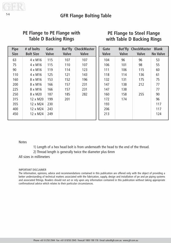
5-6
Pipe # of bolts Gate But’fly CheckMasterSize Bolt Size Valve Valve Valve
63 4 x M16 115 107 10775 4 x M16 115 110 10790 4 x M16 119 114 123110 4 x M16 125 121 143160 8 x M16 153 152 196200 8 x M16 166 157 231225 8 x M16 166 157 231250 8 x M20 187 185 282315 12 x M20 199 201355 12 x M24 230400 12 x M24 243450 12 x M24 249
Notes1) Length of a hex head bolt is from underneath the head to the end of the thread.2) Thread length is generally twice the diameter plus 6mm
All sizes in millimeters
IMPORTANT DISCLAIMERThe information, opinions, advice and recommendations contained in this publication are offered only with the object of providing abetter understanding of technical matters associated with the fabrication, supply, design and installation of pe and pe piping systemsand associated fittings. Readers should not act or rely upon any information contained in this publication without taking appropriateconfirmational advice which relates to their particular circumstances.
Gate But’fly CheckMaster BlankValve Valve Valve No Valve
104 96 96 53106 101 98 55111 106 115 60118 114 136 61132 131 175 75147 138 212 77147 138 77160 158 255 90172 174 96193 117206 117213 124
PE Flange to PE Flange with Table D Backing Rings
PE Flange to Steel Flangewith Table D Backing Rings

GFR Flange Bolting Table
Bolt Calculations Table for T/E Flanges
Phone +61 8 250 2944 Fax +61 8 9250 2945 Freecall 1800 199 176 Email [email protected] www.gfr.com.au
5-7
Pipe Flange BUP CheckMaster Gate Butterfly Steel NutSize x 2 x 2 Valve Valve Valve Flange Allowance
63 28 20 43 51 43 11 2075 28 20 43 51 46 13 2090 28 22 55 51 46 16 20110 28 26 75 57 53 17 20160 50 34 100 57 56 17 20200 50 38 135 70 61 19 20225 50 38 70 61 19 20250 60 44 165 70 68 19 25315 60 50 197 76 78 22 25355 80 58 225 76 78 25 30400 80 64 250 89 102 25 30450 80 70 89 114 29 30
Notes1) Length of a hex head bolt is from underneath the head to the end of the thread.2) Thread length is generally twice the diameter plus 6mm
All sizes in millimeters
IMPORTANT DISCLAIMERThe information, opinions, advice and recommendations contained in this publication are offered only with the object of providing abetter understanding of technical matters associated with the fabrication, supply, design and installation of pe and pe piping systemsand associated fittings. Readers should not act or rely upon any information contained in this publication without taking appropriateconfirmational advice which relates to their particular circumstances.

GFR Flange Bolting Table
Phone +61 8 250 2944 Fax +61 8 9250 2945 Freecall 1800 199 176 Email [email protected] www.gfr.com.au
5-8
Notes1) Length of a hex head bolt is from underneath the head to the end of the thread.2) Thread length is generally twice the diameter plus 6mm
All sizes in millimeters
IMPORTANT DISCLAIMERThe information, opinions, advice and recommendations contained in this publication are offered only with the object of providing abetter understanding of technical matters associated with the fabrication, supply, design and installation of pe and pe piping systemsand associated fittings. Readers should not act or rely upon any information contained in this publication without taking appropriateconfirmational advice which relates to their particular circumstances.
Gate But’fly CheckMaster BlankValve Valve Valve No Valve
106 98 98 55108 103 100 57112 107 116 61121 117 139 64141 140 184 84158 149 223 88158 149 88166 164 261 96183 185 107200 124216 127223 134
Pipe # of bolts Gate But’fly CheckMasterSize Bolt Size Valve Valve Valve
63 4 x M16 119 111 11175 4 x M16 119 114 11190 4 x M16 121 116 125110 4 x M16 131 127 149160 8 x M20 166 165 209200 8 x M20 183 174 248225 8 x M20 183 174 248250 12 x M20 199 197 294315 12 x M24 216 218355 12 x M24 244400 12 x M24 263450 16 x M24 269
PE Flange to PE Flange with Table EBacking Rings
PE Flange to Steel Flange withTable E Backing Rings

Supraclamp Jointing Systems
Phone +61 8 250 2944 Fax +61 8 9250 2945 Freecall 1800 199 176 Email [email protected] www.gfr.com.au
5-9
The coupling ‘A’ which consists of twohalves, incorporates a broad rubber gasketfor sealing and a row of serrated teeth, ateither end of the coupling, which gripssecurely on the outside of the pipe whenthe two halves are bolted together.
The Supra clamp ‘D’ adapter is used whereplain ended pipe is required to adapt tosteel shouldered pipe or fittings. Theadaptor incorporates half a coupling andgasket with the other half containing theserrated grip rings.
The Supraclamp flange adaptor consists oftwo parts:1) The actual flange adaptor ‘E’ which
contains the rubber sealing ring AND2) The Gripping clamp ‘C’ incorporating
machined teeth which grip the flangeto the outside of the pipe.
Makes joining polyethylene pipelines simple

Supraclamp Jointing Systems
Phone +61 8 250 2944 Fax +61 8 9250 2945 Freecall 1800 199 176 Email [email protected] www.gfr.com.au
5-10
The Supraclamp Jointing System is the fastest and most effective way of joining polyethylene pipingsystems without the need of welding or costly flanges. The Supraclamp system allows you to join plainended pipe up to 315mm dia. In underground or open cut mining application. The simple use of a sawenables the fitting of valves, bends etc., or the shortening of a pipe without the use of glue, welding ormake up pieces.
Bolted Coupling—Size and WeightPipe O.D X Y Z Mass
(mm) (mm) (mm) (mm) (kg)
110 150 195 150 5.0160 206 270 164 9.0200 246 310 164 12.8250 296 360 186 15.0280 326 390 186 17.5315 360 425 186 20.0
Material Specifications:Clamp—S.G. IronAS 1831Gasket —Nitrile Rubber / 75mm width all sizesBolts galvanised cupheadWorking pressure up to 2.1 mPaManufactured in accordance with ISO 9002
Installation
The Supraclamp uses a system of machined grip teeth which clamp securelyon the outside of the pipe, eliminated the need of flanges, stubs or shoulders.To join two pipe, simply fit the two square ends into the rubber gasketand bolt the two SG Iron shells together using galvanised bolts provided.
Size Range A coupling 110 to 315mmD coupling Shld Adaptor 110 to 200mmE 7 C coupling Flange Adaptor 110 to 200mm
Other sizes available on request
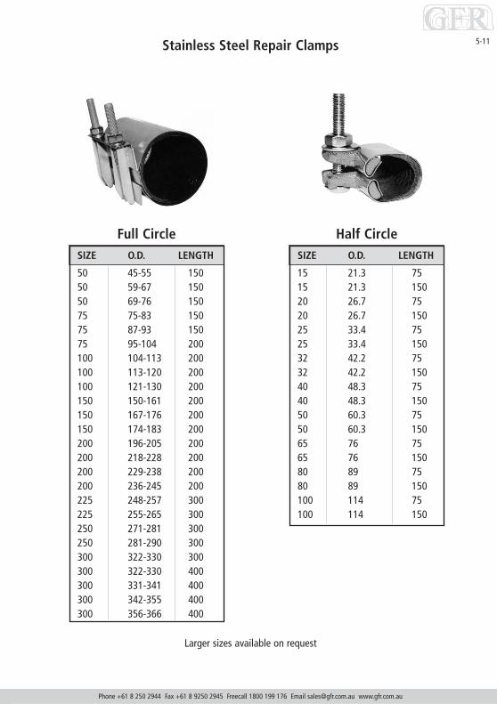
Stainless Steel Repair Clamps
Phone +61 8 250 2944 Fax +61 8 9250 2945 Freecall 1800 199 176 Email [email protected] www.gfr.com.au
5-11
Larger sizes available on request
Full CircleSIZE O.D. LENGTH
50 45-55 15050 59-67 15050 69-76 15075 75-83 15075 87-93 15075 95-104 200100 104-113 200100 113-120 200100 121-130 200150 150-161 200150 167-176 200150 174-183 200200 196-205 200200 218-228 200200 229-238 200200 236-245 200225 248-257 300225 255-265 300250 271-281 300250 281-290 300300 322-330 300300 322-330 400300 331-341 400300 342-355 400300 356-366 400
Half CircleSIZE O.D. LENGTH
15 21.3 7515 21.3 15020 26.7 7520 26.7 15025 33.4 7525 33.4 15032 42.2 7532 42.2 15040 48.3 7540 48.3 15050 60.3 7550 60.3 15065 76 7565 76 15080 89 7580 89 150100 114 75100 114 150

Phone +61 8 250 2944 Fax +61 8 9250 2945 Freecall 1800 199 176 Email [email protected] www.gfr.com.au
5-12 Stainless Steel Repair Clamps
54 Junior Couplings
SIZE O.D. LENGTH
to suit GALVANISED PIPE
15 21.3 7515 21.3 15020 26.7 7520 26.7 15025 33.4 7525 33.4 15032 42.2 7532 42.2 150
to suit COPPER PIPE
15 12.7 7515 12.7 15020 19.05 7520 19.05 15025 25.4 7525 25.4 15032 31.75 7532 31.75 15040 38.1 7540 38.1 150

Phone +61 8 250 2944 Fax +61 8 9250 2945 Freecall 1800 199 176 Email [email protected] www.gfr.com.au
5-13Tapping Bands
NOM OD TAPPINGPIPE SIZESIZE
PVC40 48 1/2" to 1"50 60 1/2" to 11/2"65 75 1/2" to 11/2"80 89 1/2" to 2"
100 114 1/2" to 2"125 140 1/2" to 2"150 160 1/2" to 2"155 168 1/2" to 2"175 200 1/2" to 2"195 219 1/2" to 2"200 225 1/2" to 2"225 250 1/2" to 2"250 280 1/2" to 2"300 315 3/4" to 2"375 315 1" to 2"400 451 1" to 2"450 500 1" to 2"
NOM OD TAPPINGPIPE SIZESIZE
AC, CI, BPVC50 70 1/2" to 1"58 78 1/2" to 11/2"80 96 1/2" to 2"
100 122 1/2" to 2"150 177 1/2" to 2"200 232 1/2" to 2"225 259 1/2" to 2"250 286 3/4" to 2"300 345 3/4" to 2"375 425 1" to 2"450 507 1" to 2"
For use on PVC AS/NZ1477-1996 also fitsGALVANISED STEEL PIPE AS1074-1988
60A For use on ASBESTOS CEMENT AS1711-1975,CAST IRON AS2544-1983 and BLUE PVC
60B
Lip Seal also available upon request

Phone +61 8 250 2944 Fax +61 8 9250 2945 Freecall 1800 199 176 Email [email protected] www.gfr.com.au
5-14
Tapping Bands
60C For use on POLYTETHYLENE PIPEAS/NZ4130-1997
60C
NOM PIPE OD TAPPING SIZESIZE
HDPE, MDPE63 63 1/2" to 11/4"75 75 1/2" to 11/2"90 90 1/2" to 11/4"
110 110 1/2" to 2"160 160 1/2" to 2"180 180 1/2" to 2"200 200 1/2" to 2"225 225 1/2" to 2"250 250 1/2" to 2"280 280 1/2" to 2"315 315 1/2" to 2"400 400 1" to 2"
Lip Seal also available upon request

Technical Information, SWJ Fittings, uPVC Pressure Pipe & Fittings
SECTION 6

Standard Dimensions and Weights PVC Non Pressure Pipes
Phone +61 8 250 2944 Fax +61 8 9250 2945 Freecall 1800 199 176 Email [email protected] www.gfr.com.au
6-1
DrainageWaste &
VentDWVPipe
AS/NZ1260
STORMWATERPIPESAS/NZ1254
Nominal MEAN O.D. APPROX. WALL AVERAGE APPROX.THICKNESS (mm) BORE WEIGHT
Size Min Max Kg/6m
32 36.2 36.5 2 32 2
40 42.8 43.1 2 38 2
50 55.7 56.0 2 50 3
65 68.7 69.1 2 63 5
80 82.3 82.7 3 76 7
SN6 100 110.0 110.4 3 103 10
SN4 150 160.0 160.5 4 151 19
SN4 225 250.0 250.7 6 236 46
SN4 300 315.0 315.9 8 297 72
SN8 150 160.0 160.5 5 150 23
SN8 225 250.0 250.7 8 233 58
SN8 300 315.0 315.9 10 293 90
90 90.0 90.3 2 86 4
150 160.0 160.5 3 154 14
225 250.0 250.7 4 240 18
300 315.0 315.9 6 303 57
Table 1

Pipe
Out
side
45
m H
ead
60m
Hea
d90
m H
ead
Dia
met
er0.
45M
pa0.
6Mpa
0.9M
pa45
0kPa
PN
4.5
600k
Pa P
N6
900k
Pa P
N9
Nom
O.D.
Mea
nAv
eW
gtM
ean
Ave
Wgt
Mea
nAv
eW
gtSi
zeD
Min
DM
axBo
reW
all
Kg/m
Bore
Wal
lKg
/mBo
reW
all
Kg/m
1521
.221
.5
2026
.626
.9
2533
.433
.7
3242
.142
.438
.51.
90.
3
4048
.148
.445
.21.
60.
344
.12.
10.
4
5060
.260
.556
.81.
80.
555
.22.
60.
7
6575
.275
.572
.01.
70.
671
.02.
20.
768
.93.
31.
1
8088
.789
.184
.92.
00.
883
.72.
61.
081
.33.
81.
5
100
114.
111
4.5
109.
32.
51.
310
7.8
3.3
1.6
104.
64.
92.
4
125
140.
014
0.4
134.
13.
11.
913
2.2
4.0
2.5
128.
45.
93.
6
150
160.
016
0.5
153.
43.
52.
515
1.3
4.5
3.2
146.
96.
74.
7
155
168.
016
8.5
158.
74.
83.
615
4.2
7.1
5.2
195
218.
821
9.4
210.
74.
24.
120
8.0
5.6
5.4
202.
78.
27.
9
200
225.
022
5.6
216.
74.
34.
321
3.8
5.8
5.7
208.
58.
48.
3
225
250.
025
0.7
240.
84.
85.
423
7.7
6.4
7.1
231.
79.
410
.3
250
280.
028
0.8
269.
75.
46.
726
6.2
7.1
8.8
259.
410
.512
.9
300
315.
031
5.9
303.
46.
18.
529
9.5
8.0
11.2
292.
011
.816
.2
375
400.
040
1.0
385.
27.
713
.738
0.3
10.1
18.0
370.
714
.926
.2
Stan
dard
Dim
ensi
ons
and
Wei
ghts
PV
C Pr
essu
re P
ipes
- A
S/N
Z147
7-19
96 S
erie
s 1
Phone +61 8 250 2944 Fax +61 8 9250 2945 Freecall 1800 199 176 Email [email protected] www.gfr.com.au
6-2
120m
Hea
d15
0m H
ead
180m
Hea
d1.
20 M
pa1.
50 M
pa1.
80 M
pa12
00kP
a PN
1215
00kP
a PN
1518
00kP
a PN
18
Mea
nAv
eW
gtM
ean
Ave
Wgt
Mea
nAv
eW
gtBo
reW
.T.
Kg/m
Bore
W.T
.Kg
/mBo
reW
.T.
Kg/m
18.3
1.6
0.1
17.8
1.8
0.2
23.7
1.6
0.2
23.0
1.9
0.2
22.4
2.2
0.2
29.8
1.9
0.3
29.0
2.3
0.3
28.1
2.8
0.4
37.5
2.4
0.4
36.4
3.0
0.5
35.4
3.5
0.6
42.8
2.8
0.6
41.6
3.4
0.7
40.5
3.9
0.8
53.7
3.4
0.9
52.2
4.1
1.1
50.5
5.0
1.3
67.0
4.2
1.4
65.1
5.2
1.7
63.2
6.1
1.9
79.0
5.0
1.9
76.7
6.1
2.3
74.6
7.2
2.7
101.
76.
33.
298
.87.
83.
896
.09.
24.
5
124.
97.
74.
712
1.3
9.5
5.8
117.
711
.36.
8
142.
78.
86.
213
8.7
10.8
7.6
134.
712
.88.
9
149.
59.
46.
914
5.6
11.4
8.3
141.
413
.59.
8
180.
69.
98.
8
195.
211
.812
.0
203.
111
.111
.2
225.
812
.313
.7
252.
913
.817
.3
284.
515
.522
.2
361.
219
.736
.0
Tabl
e 2

Standard Dimensions and Weights
Vinyl Iron Pipe
PVC Bore Casing
Nominal Size Minimum O.D. Maximum O.D. Average Wall Mean Bore Weight kg/mThickness
100 114.1 114.5 4.5 104.6 2.4
125/6 140 140.4 4 132.2 2.5
125/9 140 140.4 5.9 128.4 3.6
125/12 140 140.4 7.7 124.9 4.6
150/9 160 160.5 6.7 146.9 4.7
155/9 168 168.5 7.1 154.2 5.2
155/12 168 168.5 9.2 149.9 6.7
Nom Mean O.D. Mean Ave Wgt Mean Ave Wgt Mean Ave Wgt Mean Ave Wgt Mean Ave WgtSize Min Max Bore W.T. Kg/m Bore W.T. Kg/m Bore W.T. Kg/m Bore W.T. Kg/m Bore W.T. Kg/m
100 121.7 122.2 108.5 6.7 3.6 100.3 10.8 5.7
150 177.1 177.6 157.9 9.8 7.8 146.1 15.7 12.1
200 231.9 232.6 209.3 11.5 12.0
250 285.5 286.5 257.8 14.1 18.3
375 425.7 426.7 410.0 8.1 16.4 404.8 10.7 64.7 394.5 15.9 31.5 384.4 20.9 40.9
Class 4.5 (PA) Class 6 (PB) Class 9 (PC) Class 12 (PD) Class 18 (PF)45m Head 60m Head 90m Head 120m Head 180m Head0.45Mpa 0.6Mpa 0.9Mpa 1.2Mpa 1.8Mpa
Phone +61 8 250 2944 Fax +61 8 9250 2945 Freecall 1800 199 176 Email [email protected] www.gfr.com.au
6-3
Table 3
Table 4

uPVC Pressure Pipe and Fittings Technical Information
Temperature Considerations
For uPVC pipes and fittings under pressure and in continuous service at any temperature in the range 20-60°C,the maximum allowable static pressure shall be reduced in accordance with the values in Table 3. For any pipematerial temperature or any pressure outside this range, the maximum allowable static pressure should beestablished by reference to our office.
Table 5. Rating for pressure pipes for temperature.
Note: Pipes of higher rating than Class 18 should be rated in the same proportions as for Class 18.
Table 6. Recommended spacing of supports in metres.
uPVC pipe should be supported at intervals depending on the density of the fluid being conveyed and themaximum temperature likely to be reached by the pipe material. Table 6 shows recommended maximum spacingof support for all classes of pipe where water is the fluid being conveyed.
Where ambient temperatures or the temperatureof piped fluids are such that the temperature ofthe material is likely to be greater than 20°C, thesupport distances should be reduced accordingly.
Where material temperatures are likely toapproach 60°C and the pipe is horizontal,continuous support of the pipe is recommended;for vertical installations the values at Table 6 forhorizontal support should be used.
Heavy fittings such as valves should be supportedindependently, and large plastic fittings (e.g.flanges, particularly those with metal backingrings) should be supported on each side. Wherepipes are continuously supported, flangedconnections and other protrusions should beallowed room for movement.
Maximum allowable static pressure - MpaPipe Mat. Class 4.5 Class 6 Class 9 Class 12 Class 15 Class 18
temp.
20°C 0.45 0.60 0.90 1.20 1.50 1.8030°C 0.36 0.48 0.72 0.96 1.20 1.4440°C 0.27 0.36 0.54 0.72 0.90 1.0850°C 0.18 0.24 0.36 0.48 0.60 0.7260°C 0.09 0.12 0.18 0.24 0.30 0.36
Nom. Horizontal or Vertical pipesSize graded pipes
15 0.30 0.6020 0.35 0.7025 0.38 0.7532 0.43 0.8540 0.45 0.9050 0.50 1.0565 0.60 1.2080 0.67 1.35
100 0.75 1.50125 0.85 1.70150 1.00 2.00200 1.15 2.30225 1.25 2.50250 1.30 2.60300 1.50 3.00
Phone +61 8 250 2944 Fax +61 8 9250 2945 Freecall 1800 199 176 Email [email protected] www.gfr.com.au
6-4
Table 5
Table 6

uPVC Pressure Pipe and Fittings Technical InformationThermal Linear Expansion of uPVC Pipe
The co-efficient of thermal expansion of uPVC is much greater than other materials and must be considered wheninstalling above or below ground. The co-efficient may be taken for reference as 7 x 10⁻⁵/°C and representsapproximately 1 mm/m/15°C.
Earthing
uPVC is a non-conductor of electricity and must not be used for earthing purposes.
Storage and Handling
Because of its light weight uPVC is more liable to be thrown about, so reasonable care should be taken duringstorage and handling.
Each pipe should have continuous or evenly spaced supports. Pipes should not be stacked in large piles,particularly in warm conditions. Store away from direct sunlight whenever possible.
uPVC Pressure Fittings
The uPVC system is a comprehensive range of pressure pipes and fittings - well suited to domestic, commercialand industrial applications.
All basic components are manufactured in PVC, and subject to the most rigorous quality controls. The result is alight, robust system of a consistently high standard.
Injection moulded fittings suitable for solvent weld jointing are available in 15 mm - 150 mm and long radiuspost formed bends to 195 mm.
GFR can custom manufacture PVC fittings to your requirements.
C.I./D.I. Pressure Fittings
A comprehensive range of Cast Iron and Ductile Iron fittings are available for use with Hardiseal R.
R.J. pressure pipes.
Socketed all around fittings manufactured to suit AS1477 pressure pipe dimensions are recommended.
Hydraulic Testing
Pipe line should be cool and, if buried, all joints left exposed. All air should be eliminated before applying full testpressure. Test pressure is normally 1.2 to 1.5 times working pressure and should be no greater than twicemaximum working pressure. Test ends and any changes in direction must be properly retrained during testing toavoid movement of the pipe and fittings.
Solvent weld systems must not be subjected to any hydraulic pressure for at least 24 hours when using high bondor 48 hours when using slow setting cement.
Rubber ring joint systems must not be subjected to any hydraulic pressure until concrete thrust blocks have set.
Jointing Methods - Solvent Weld Joint
Solvent weld joints are a simple trouble free method of jointing uPVC pressure pipe and fittings, provided onlyhigh bond or slow setting solvent cement is used and these jointing instructions are carefully followed. Beforeapplying the solvent cement, it is essential to use priming fluid for successful jointing, as the fluid not only cleansand degreases, but removes the glazed surface from uPVC which allows the solvent cement to permeate into thepipe or fitting.
Solvent cement is a solution of resin in a mixture of solvents which soften the surfaces when applied to uPVCpipe and fittings. It is NOT a glue.
A thin uniform coat is applied to both spigot and socket and the joint assembled while the surfaces are still andfluid. The cement layers intermingle and become one. The strength of the joint develops as the solvent permeatesthe PVC and the volatile constituents evaporate.
Phone +61 8 250 2944 Fax +61 8 9250 2945 Freecall 1800 199 176 Email [email protected] www.gfr.com.au
6-5

uPVC Pressure Pipe and Fittings:Jointing Instructions
1. Cut the spigot as square as possible using a mitre box and handsaw orpower saw. Remove all swarf and burrs from both inside and outsideedges with a knife, file,reamer or sandpaper. Swarf and burrs if left, willwipe off the solvent cement and prevent proper joining.Also swarf insidepipes can become dislodged and jam taps and valves.
2. Check the pipe and spigot or fittings for proper alignment. The time forany adjustments is NOW, not later.
3. Mark the spigot with a pencil or marker at a distance equal to theinternal depth of the socket. Do NOT score or damage the surface of thepipe or fitting.
4. Dry fit the joint. An interference fit must be reached before the spigot isinserted fully to the pencil mark.
5. Thoroughly clean the inside of the socket and the area between thepencil mark and the spigot end with a clean cotton, lint free cloth (doNOT use synthetic material), dipping in priming fluid. This removes dirtand grease and softens the PVC surface. Do NOT brush or pour thepriming fluid on.
6. Apply a THIN, uniform coat of solvent cement to the socket. Note that apool of cement at the foot of the socket will severely weaken the pipe orfitting. Apply a uniform coat of solvent cement to the external surface ofthe spigot up to the pencil mark.
7. Assemble the joint quickly before the cement dries by pushing the spigotfirmly into the socket as far as the pencil mark, ending with a quarterturn in this position for at least thirty seconds without movement.
8. Wipe off the excess solvent cement from the outside of the joint andwhere possible from the inside of the joint. Do NOT disturb for at least afurther five minutes.
Cure time is the time taken for the solvent weld joint to reach the pressure rating of the pipe.
For pressure pipes do NOT pressure test the joint for at least 24 hours when using high bond or 48 hours whenusing slow setting.
By following these steps EXACTLY you should be able to make strong, leak-free joints with solvent cements. Butremember, correct pipe and fitting selection is also important. Consult the GFR catalogue for correct selection.
Phone +61 8 250 2944 Fax +61 8 9250 2945 Freecall 1800 199 176 Email [email protected] www.gfr.com.au
6-6
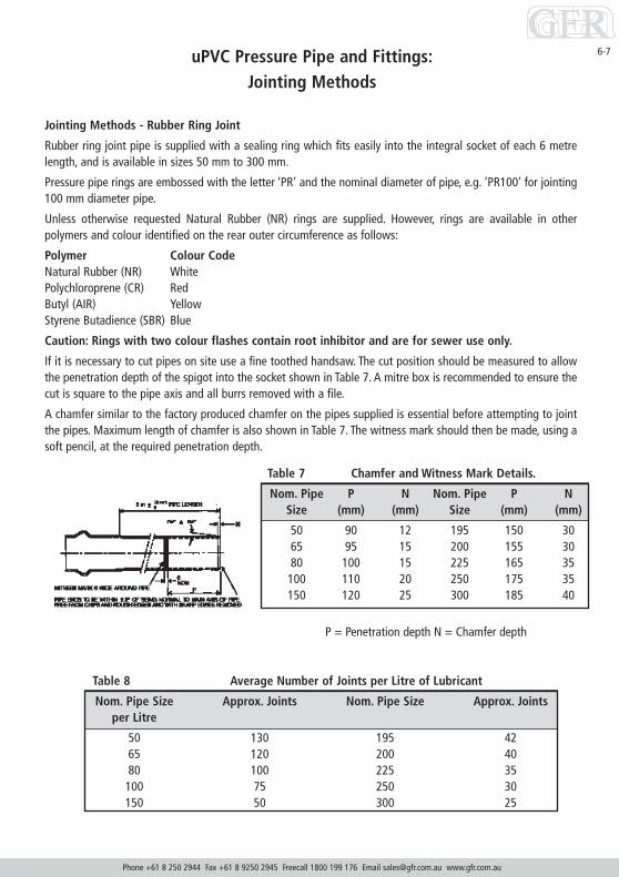
uPVC Pressure Pipe and Fittings:Jointing Methods
Jointing Methods - Rubber Ring Joint
Rubber ring joint pipe is supplied with a sealing ring which fits easily into the integral socket of each 6 metrelength, and is available in sizes 50 mm to 300 mm.
Pressure pipe rings are embossed with the letter ‘PR’ and the nominal diameter of pipe, e.g. ’PR100’ for jointing100 mm diameter pipe.
Unless otherwise requested Natural Rubber (NR) rings are supplied. However, rings are available in otherpolymers and colour identified on the rear outer circumference as follows:
Polymer Colour CodeNatural Rubber (NR) WhitePolychloroprene (CR) RedButyl (AIR) YellowStyrene Butadience (SBR) Blue
Caution: Rings with two colour flashes contain root inhibitor and are for sewer use only.
If it is necessary to cut pipes on site use a fine toothed handsaw. The cut position should be measured to allowthe penetration depth of the spigot into the socket shown in Table 7. A mitre box is recommended to ensure thecut is square to the pipe axis and all burrs removed with a file.
A chamfer similar to the factory produced chamfer on the pipes supplied is essential before attempting to jointthe pipes. Maximum length of chamfer is also shown in Table 7. The witness mark should then be made, using asoft pencil, at the required penetration depth.
Table 8 Average Number of Joints per Litre of Lubricant
Nom. Pipe Size Approx. Joints Nom. Pipe Size Approx. Jointsper Litre
50 130 195 4265 120 200 4080 100 225 35
100 75 250 30150 50 300 25
Table 7 Chamfer and Witness Mark Details.
Nom. Pipe P N Nom. Pipe P NSize (mm) (mm) Size (mm) (mm)
50 90 12 195 150 3065 95 15 200 155 3080 100 15 225 165 35100 110 20 250 175 35150 120 25 300 185 40
P = Penetration depth N = Chamfer depth
Phone +61 8 250 2944 Fax +61 8 9250 2945 Freecall 1800 199 176 Email [email protected] www.gfr.com.au
6-7

6-8 Coverage of Solvent Cements for PVC Jointing
Coverage of Solvent Cements
Elevated Service Temperature
Thermal Linear Expansion of PVC Pipe
9 FAST SET UP TO 50 mm - VX8 SLOW SET FOR LARGE BORE AND HOT CONDITIONS
PRESSURE PIPE SEWER PIPE
PIPES 15 20 25 32 40 50 80 100 155 195 100 150 225 300(mm)
APPROX NO. 600 350 260 190 140 75 60 40 25 17 50 30 15 10OF JOINTSPER LITRE
SERVICE CLASS 4.5 (PA) CLASS 6 (PB) CLASS 9 (PC) CLASS 12 (PD) CLASS 15 (PE) CLASS 18 (PF)
TEMP Mtr Hd Mpa PSI Mtr Hd Mpa PSI Mtr Hd Mpa PSI Mtr Hd Mpa PSI Mtr Hd Mpa PSI Mtr Hd Mpa PSI
20°C 45 0.45 65 60 0.60 87 90 0.90 130 120 1.20 173 150 1.50 216 180 1.80 260
30°C 36 0.36 52 48 0.48 69 72 0.72 104 96 0.90 139 120 1.20 173 144 1.44 208
40°C 27 0.27 39 36 0.36 52 54 0.54 78 72 0.72 104 90 0.90 130 108 1.08 156
50°C 18 0.18 26 24 0.24 35 36 0.36 52 48 0.48 69 60 0.60 87 72 0.72 104
60°C 0 0.09 13 12 0.12 17 18 0.18 26 24 0.24 35 30 0.30 44 36 0.36 52
Phone +61 8 250 2944 Fax +61 8 9250 2945 Freecall 1800 199 176 Email [email protected] www.gfr.com.au
Table 9
Table 10

Valves
SECTION 7

Australian Design Mark
Made from engineering plastics, stainless steel and rubber, the FloatMaster is a servo assisted valve which is operated by its 25mm pilot valve.The pilot valve is designed to ignore turbulence in the tank / vessel andshuts off positively which in turn prompts a modulated close off in themain valve. The valve simply bolts onto a flange in the tank and is readyfor use.Float Master is a valve designed to fit into a tank or vessel and to regulatethe flow of liquid being pumped into the vessel based on depth.The Float Master is designed to shut off with no “chatter” which is anindustry-recognized problem. “Chatter “ is when the waves, made by thevalve emptying into the tank, cause the ball float on the valve to bounceup and down and shut-off / open again in rapid succession. The resultingwater hammer shocks can cause damage and confuse pressure sensitiveshut-off switches etc.Float Master was designed to be easy to fit, simple to operate, and to notrequire any electrical support such as telemetry or pressure switchoperations. Another important part of the design is to ensure that the FloatMaster can be easily retrofitted into any application. This has significantimplications in the airconditioning, mining and utilities markets whereboth strategic and tactical maintenance is carried out due to corrosion andwear of valves.The extremely simple nature of installation allows for minimal downtimewhilst the light weight of the valve offers a much lower chance of strainor injury from an OH&S perspective.
Phone +61 8 250 2944 Fax +61 8 9250 2945 Freecall 1800 199 176 Email [email protected] www.gfr.com.au
7-1

Master Valves
The Story behind the Master Valve DevelopmentSince GFR's inception in 1986 we have seen more and more creative applicationsand innovations in the PE pipeline business. Engineers and end-users haveembraced PE as a worthy replacement for stainless steel, carbon steel, rubberlined pipe, PVC pipe and others.
The ChallengeValves are an area where we as an industry have seen virtually no changes occur.This problem has really been highlighted in applications where PE has beenspecified for its abrasion/corrosion resistance and no valving has been availableto complement the PE. The unfortunate result is that it is usual to see a PEpipeline performing to design for, say, a highly saline process water supply whileall around it there is either a tactical or strategic maintenance programme thatdeals with corroding and failing components such as valves. Problems in suchcircumstances include:• Corroding valves• Blocked valves• Pipeline collapsing under vacuum• Increased energy consumption caused by trapped air• Pipelines failing due to trapped air
The SolutionGFR has spent years supplying spare parts, new valves and other components,performing in field repairs and making customised fittings for frustrated end-users who have an otherwise functional pipeline.We have viewed this as an opportunity to develop a better range of valves thatwill complement your pipeline through effective and economic service.What materials would you prefer your valves to be made of? - Our experiencetells us that corrosion proof materials that have good wear resistance arepreferred.
Raw MaterialsGFR's "Master" range is based on three component materials that arecomplemented by other materials depending on model. These materials are:• Stainless Steel (316 and SAF)• Natural Rubber• Polyethylene/Ertacetal
Please don't hesitate to contact us with any questions!
Vent Master Valve
Vent Master Sewer Valve
Check Master Valve
Float Master Valve
Foot Valve
Phone +61 8 250 2944 Fax +61 8 9250 2945 Freecall 1800 199 176 Email [email protected] www.gfr.com.au
7-2

7-3
Vent Master*
Removing air:
1. Increases water meter accuracy.
2. Decreases corrosion in steel or metal lines.
3. Decreases pump cavitation.
4. Increases flow rates/decreases pumping costs.
Introducing air:
1. Prevents vacuum collapse of plastic pipes (especially hdpe and pp).
2. Prevents column separation.
3. Allows for better evacuation when emptying line.
• It is generally recommended that valves are positioned every 500 mtrs in a normallyflowing pipeline and at each high point/change of slope.
• Valves should always be installed in conjunction with an isolation valve.
• No valve of comparable size performs better than the Vent Master from GFR.
• Available in non-slam (anti-shock) configuration for prevention of compressionshocks in the pipeline.
• Full size large orifice for high air-transit performance.
• Solid 316SS and engineering plastics construction for superior corrosionresistance. In critical areas, engineering plastics offer less friction resistance forsuperior expulsion of solid contaminants.
• Automatic anti-clog configuration for better expulsion of solid contaminants.
• Simple design for quick installation and economical operation.
• Standard bsp threads in 25mm and 50mm. Larger sizes are flanged in table E.Other flange tables or mounting configurations can be supplied on request.
Manufactured by :
GFR Industries, 8 Artello Bay Road, Midvale, Western Australia 6056
Phone: (08) 9250 2944, Facsimile: (08) 9250 2945, Freecall: 1800 199 176
Email: [email protected], Website: www.gfr.com.au
Distributed by :
*(patent pending)
Why do I need anair release/
vacuum break valve?
Installation notations:
Some terms andrecommendations:
Australia’s own high rate air release/vacuum break valveAustralia and the World’s new solution for arvb.
ARVB: air-release/vacuum break.
CPR: critical pressure ratio. Maximum differential pressure across an orifice whereincreased pressure in line will not increase airflow.
Dynamic closure is when: the large orifice of the valve is closed-off when theinternal float is uplifted by out-rushing air.
Kinetic closure is when: the large orifice and the auto orifice are closed when the float is buoyed by the entry of water into the valve.
Automatic venting is when: air is vented via the automatic orifice under pressurisedconditions.
Vacuum breaking is when: air is inhaled through the valve and into the pipelineduring pipeline draining.
Non slam is recommended: 1. where an arvb is positioned at the end of a pipeline. 2. where column separation may occur.3. on bore-heads and pumps.
Phone +61 8 250 2944 Fax +61 8 9250 2945 Freecall 1800 199 176 Email [email protected] www.gfr.com.au

Phone +61 8 250 2944 Fax +61 8 9250 2945 Freecall 1800 199 176 Email [email protected] www.gfr.com.au
7-4
Vent Master* (cont.)
Combined Air Release/Vacuum Brake Valve
Vent Master Air Valve Configuration
GFR warranty: "The manufacturer (GFR) guarantees its valves for any defects in materials or manufacture for a period of one year from the original date ofpurchase, as long as the valves have been used under normal operating conditions. GFR's liability under this warranty is limited to the replacement or repair ofthe defective valve. GFR does not accept any consequential damages deriving from defects in the valves covered by this warranty. To the fullest extent the lawpermits, the warranty supersedes and voids all other warranties, whether expressed or implied (regardless of whether by agreement, conduct, statute orotherwise), including, without limitation, that of merchantability and fitness for particular purposes. No employee, representative or agent of GFR is authorised tovoid, alter or add to the conditions contained in this warranty, nor to take responsibility for, nor make guarantees not specified herein."

7-5
Check Master*
• Solid HDPE body with an elastomeric sealing element ensures high abrasion andcorrosion resistance. In sizes up to 200mm, the sealing element is mouldedaround a stainless steel insert. In sizes over 200mm the sealing element is boltedto the stainless steel flap.
• The single, large flow opening provides efficient, obstruction-free, non-cloggingoperation combined with low friction loss.
• Positive return action and drop tight sealing for long term reliability.
• Lightweight design for easy handling and installation.
• Only one moving part for minimised wear.
• Patented design and elastomeric hinge means that no spring is required.
• Availability in 50mm through to 500mm sizes means that Check Master offersan effective choice of sizes allowing specification into most applications.
• In many instances, Check Master valves can be used in the place of valves madefrom much more expensive and exotic materials.
• Re-configured and custom versions such as alternative materials of constructionand foot-valves are routinely made. Contact your supplier regarding options.
• Polyethylene. (UV stabilised)
• Stainless Steel. (SAF and 316)
• Natural rubber.
• Mining (gold, coal, aluminium, copper,iron ore, base metals etc.).
• Mineral processing (refining, electrowinning, electro-refining).
• Potable water pipelines.
• Irrigation.
• Sewage pipelines and treatment.
• Power Stations.
• Chemicals.
• Petro-chemicals.
• Cement production.
Now into its second decade of successful use, the Check Master valve is the simpleand economical non-return valve which was designed specifically for use in aggressive,corrosive and highly abrasive environments.
Since release, the Check Master has been embraced by industry for many uses otherthan those for which it was originally designed. Some of these other uses includesewage, fine particles and powders, gases and vapour recovery, potable water,irrigation, and others.
The Check Master valve can be installed horizontally or vertically and features aspool design with a short face-to-face dimension. The valve nips between pipeflanges. It is suitable for use with pressures up to 1400kpa (50mm to 250mm)@ 20˚C, and 1000kpa (300mm to 500mm) @ 20˚C. Specific working pressurerequirements can be accommodated, please ask.
Manufactured by :
GFR Industries, 8 Artello Bay Road, Midvale, Western Australia 6056
Phone: (08) 9250 2944, Facsimile: (08) 9250 2945, Freecall: 1800 199 176
Email: [email protected], Website: www.gfr.com.au
Distributed by :
*(patented)
Materials ofconstruction:
The Check master valveis ideally suited
for use in:
The simply better non-return valve.
The Check Masteris wholly designedand manufactured
in Australia.Its features include:
GFR warranty: "The manufacturer (GFR) guarantees its valves for any defects in materials or manufacture for aperiod of one year from the original date of purchase, as long as the valves have been used under normal operatingconditions. GFR's liability under this warranty is limited to the replacement or repair of the defective valve. GFRdoes not accept any consequential damages deriving from defects in the valves covered by this warranty. To thefullest extent the law permits, the warranty supersedes and voids all other warranties, whether expressed orimplied (regardless of whether by agreement, conduct, statute or otherwise), including, without limitation, that ofmerchantability and fitness for particular purposes. No employee, representative or agent of GFR is authorised tovoid, alter or add to the conditions contained in this warranty, nor to take responsibility for, nor make guaranteesnot specified herein."
Phone +61 8 250 2944 Fax +61 8 9250 2945 Freecall 1800 199 176 Email [email protected] www.gfr.com.au

7-6 Check Master* (cont.)
Phone +61 8 250 2944 Fax +61 8 9250 2945 Freecall 1800 199 176 Email [email protected] www.gfr.com.au

7-7
Float Master*
Manufactured by :
GFR Industries, 8 Artello Bay Road, Midvale, Western Australia 6056
Phone: (08) 9250 2944, Facsimile: (08) 9250 2945, Freecall: 1800 199 176
Email: [email protected], Website: www.gfr.com.au
Distributed by :
*Patents pendingSouth African Patent No. 2001/5207
The SuperiorFloat Valve
GFR warranty: "The manufacturer (GFR) guarantees its valves for anydefects in materials or manufacture for a period of one year from theoriginal date of purchase, as long as the valves have been used undernormal operating conditions. GFR's liability under this warranty is limited tothe replacement or repair of the defective valve. GFR does not accept anyconsequential damages deriving from defects in the valves covered by thiswarranty. To the fullest extent the law permits, the warranty supersedesand voids all other warranties, whether expressed or implied (regardless ofwhether by agreement, conduct, statute or otherwise), including, withoutlimitation, that of merchantability and fitness for particular purposes. Noemployee, representative or agent of GFR is authorised to void, alter or addto the conditions contained in this warranty, nor to take responsibility for,nor make guarantees not specified herein."
The Float Master pilot operated float valve
is designed to satisfy industry needs for a
low maintenance, full flow valve for
service in many environments. This
premium valve is wholly designed and
manufactured in Australia and offers
benefits to both designers and end-users:
Now exportedto 6 countries.
Phone +61 8 250 2944 Fax +61 8 9250 2945 Freecall 1800 199 176 Email [email protected] www.gfr.com.au
• Available in 50mm,80mm,100mm,150mm, 200mm. Larger versionsmanufactured on request.
• Pilot valve can be remote located either on a rigid stainless steel riser, or on aflexible high pressure capillary hose.
• Pilot valve can be operated by a remote pressure source if required.
• Simple design for economical and trouble free operation.
• Unique pilot-valve IGNORES WAVE ACTION AND TURBULENCE. The positive-but-softshutoff ensures that wear and tear on pumps, pressure switches and piping isminimal.
• Solid 316SS and Ertalon® (cast nylon) construction for superior corrosiontolerance.
• No “chatter”........pilot valve is tolerant to surface water turbulence.
• No “throttling”........the valve operates at full flow through its entire operating cycle.
• Full flow design to minimise pressure loss and blockages.
• Hydraulic closure for drop tight shut-off at all pressures within operating range.
• Lightweight construction for ease of installation.
• Simple flanged installation in table E (standard), D or ANSI. Threaded units can be furnished if required. Widely used in mining and process applications, fire systems, rural and metro water supply applications with WA Water Corporation.

7-8
Phone +61 8 250 2944 Fax +61 8 9250 2945 Freecall 1800 199 176 Email [email protected] www.gfr.com.au


Ball Valves
Phone +61 8 250 2944 Fax +61 8 9250 2945 Freecall 1800 199 176 Email [email protected] www.gfr.com.au
7-11
BRASS BALL VALVEFF BSP (FULL BORE)
SIZE (mm)
15203240506580
100
PVC DOUBLE UNIONBALL VALVE SLIP
SIZE (mm)
152025324050
PVC BALL VALVE SLIPSIZE (mm)
152025324050
PVC BALL VALVE FFBSP
SIZE (mm)
1520253240506580
100
PVC DOUBLE UNIONBALL VALVE FF BSP
SIZE (mm)
324050
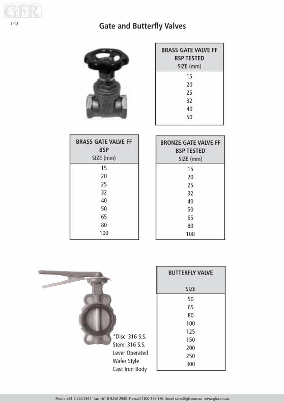
Gate and Butterfly Valves
Phone +61 8 250 2944 Fax +61 8 9250 2945 Freecall 1800 199 176 Email [email protected] www.gfr.com.au
7-12
BUTTERFLY VALVE
SIZE
506580
100125150200250300
BRASS GATE VALVE FFBSP
SIZE (mm)
1520253240506580
100
BRASS GATE VALVE FFBSP TESTED
SIZE (mm)
152025324050
BRONZE GATE VALVE FFBSP TESTED
SIZE (mm)
1520253240506580
100
*Disc: 316 S.S.Stem: 316 S.S.Lever OperatedWafer StyleCast Iron Body

PE B
utte
rfly
Val
ve S
pace
rs
Phone +61 8 250 2944 Fax +61 8 9250 2945 Freecall 1800 199 176 Email [email protected] www.gfr.com.au
7-13
Butt
erfly
Pipe
SDR
9SD
R 11
SDR
13.6
Valv
e N
BO.
D.A
BC
d°A
BC
d°A
BC
d°
100
110
8416
014
3089
160
1420
125
125
9619
225
3010
219
225
2510
619
225
25
125
140
106
192
2525
114
192
2520
119
192
2515
150
160
123
213
2530
130
213
2525
136
213
2520
200
200
154
270
4035
162
270
4030
170
270
4025
200
225
173
270
4025
183
270
2525
191
270
2520
250
250
192
334
6030
203
334
6025
212
334
3035
250
280
215
334
4030
228
334
3030
238
334
3025
300
315
242
380
6035
256
380
6030
268
380
4030
350
355
273
444
100
2528
944
460
3030
244
460
25
400
400
308
495
100
2532
549
510
025
340
495
6030
450
450
346
545
100
3036
654
510
025
382
545
6030
500
500
385
602
100
3040
760
210
025
425
602
5030
600
630
513
708
5520
535
708
5525
700
710
603
812
100
35
800
800
680
948
140
30
1000
1000
Butt
erfly
val
ve n
omin
al b
ore
size
,pip
e ou
tsid
e di
amet
er,
SDR
and
PN ra
ting
to b
esp
ecifi
ed
Dim
ensi
ons
in m
m
SDR
17SD
R 21
SDR
26SD
R 33
AB
Cd°
AB
Cd°
AB
Cd°
AB
Cd°
1119
225
2011
192
2520
1421
325
20
1727
025
3018
270
2525
1827
025
2518
270
2520
2233
430
3022
334
3025
2333
430
2523
334
3025
2433
430
20
2738
030
3028
380
3025
2938
030
20
3144
440
3031
444
4025
3344
440
2533
444
4020
3549
540
3036
495
4025
3749
540
2537
495
4020
3954
560
3040
545
4030
4254
540
2542
545
4020
4460
250
2545
602
5020
5020
6281
210
2563
812
6035
6681
260
3066
812
6020
7094
810
3072
948
1030
7594
810
2575
948
6030
8811
314
3090
1156
1430
9411
3610
3094
1136
1025
Specialised Fabrications
SECTION 8

Chemical tanks in fabricated engineering plastics
Phone +61 8 250 2944 Fax +61 8 9250 2945 Freecall 1800 199 176 Email [email protected] www.gfr.com.au
8-1
Materials of construction:� HDPE� PVC� Polypropylene� PVDFLatest design software calculates tanks and vessels in engineering plastics to suit your applications.
PHOTO : HDPE fluorosilisic acid storage tank for the WA WaterCorporation.12,800ltr capacity.Designed, fabricated and guaranteed for 10 years by GFR.Design, fabrication and materials to DVS standards. Butt welded for increased strength and integrity on Australia’slargest and newest sheet butt welder.

Specialised Fabrications
TanksThe best available specialised tanks in engineering plastics for the A(Acetic acid) to Z (Zinc Sulphate) of chemicals.• Using the unique “RITA” tank design software from Germany
means that a design to DVS standards is generated to match yourspecific requirement.
• Using GFR’s huge 3 metre butt welder allows plastic sheet of upto 3mtr x 50mm thick to be butt welded therefore creating thestrongest tank cylinders available.
• Offering guarantees of up to 10 years and longer if required, GFRis protecting your investment through the provision of superiordesign, superior materials, and superior fabrication.
Phone +61 8 250 2944 Fax +61 8 9250 2945 Freecall 1800 199 176 Email [email protected] www.gfr.com.au
8-2

Tank Enquiry Form
Phone +61 8 250 2944 Fax +61 8 9250 2945 Freecall 1800 199 176 Email [email protected] www.gfr.com.au
Company Date
Contact GFR Quote No.
Project Date
Phone Email
Fax
Please use this form to aid GFR technical staff in attending to your enquiry.
Tank Name:Tank Size:
LengthWidthHeightDiameterVoid Volume
Volume Capacity:Pressure:Temp/Deg. C:
Chemical % Conc.
Medium:(List Chemicals present inc.
concentration)
Baffles (Yes/No):Flat or Coned Roof:Site Location:Inside/Outside:Nozzles/Inlets/Outlets
Number of:Size:
Information Required:
Sketch (or attach drawing)
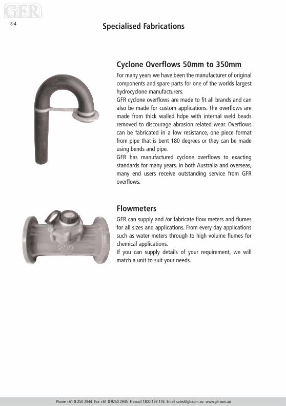
Specialised Fabrications
Phone +61 8 250 2944 Fax +61 8 9250 2945 Freecall 1800 199 176 Email [email protected] www.gfr.com.au
8-4
Cyclone Overflows 50mm to 350mmFor many years we have been the manufacturer of originalcomponents and spare parts for one of the worlds largesthydrocyclone manufacturers.GFR cyclone overflows are made to fit all brands and canalso be made for custom applications. The overflows aremade from thick walled hdpe with internal weld beadsremoved to discourage abrasion related wear. Overflowscan be fabricated in a low resistance, one piece formatfrom pipe that is bent 180 degrees or they can be madeusing bends and pipe.GFR has manufactured cyclone overflows to exactingstandards for many years. In both Australia and overseas,many end users receive outstanding service from GFRoverflows.
FlowmetersGFR can supply and /or fabricate flow meters and flumesfor all sizes and applications. From every day applicationssuch as water meters through to high volume flumes forchemical applications.If you can supply details of your requirement, we willmatch a unit to suit your needs.

Specialised Fabrications
Suction Strainers50mm—1000mm / Restricted or Full Flow
Full flow 450mm Skid Mounted Foot Valve
Phone +61 8 250 2944 Fax +61 8 9250 2945 Freecall 1800 199 176 Email [email protected] www.gfr.com.au
8-5

Specialised Fabrications
Machine GuardsMachine guards in HDPE : Safer, lighter, longer lasting, morecost effective.Machine and belt guards made from engineering plastics offermany benefits over their steel predecessors:• Low friction resistance allows for simpler and easier
cleaning. This is especially important in dusty conditions.• Yellow coloured, UV stabilised hdpe means that the guard
never needs to be painted.• HDPE does not corrode hence service life is increased over
steel units. Also, there are no unsafe jagged edges causedby corrosion
• Servicing of machinery is simplified with the use of themuch lighter plastic guards. In many cases the need forcranage is negated due to the lightness of the guards withsimpler JSA’s appreciated by many site personnel.
• Retrofitting in plastic means that modifications can beeasily carried out in manufacture. This could include clearpolycarbonate viewing windows etc.
GFR machine guards are unique. Your guards are full –penetration extrusion welded to the exacting DVS standards.Protect your people and your machinery with GFR belt guards.Call for details.
Phone +61 8 250 2944 Fax +61 8 9250 2945 Freecall 1800 199 176 Email [email protected] www.gfr.com.au
8-6

Special Application Pipes
SECTION 9

Phone +61 8 250 2944 Fax +61 8 9250 2945 Freecall 1800 199 176 Email [email protected] www.gfr.com.au
9-1
Slotted Draincoil
Unslotted draincoil and slotted draincoil with sock is also available.Please always request a lead time on non-standard products.
Ring our sales consultants for information and pricing on geofabrics, filter sock and accessories.
SIZE (MM) CLASS LTH (mtrs)
50 400 2050 400 20065 400 2065 400 20080 400 2080 400 100
100 400 20100 400 100100 1000 100160 400 20160 400 40
Draincoil Joiner100 each80 each65 each50 each
AG Pipe Soakwell Kit100 4 mtr
Soakwell Adaptor100 90mm

Phone +61 8 250 2944 Fax +61 8 9250 2945 Freecall 1800 199 176 Email [email protected] www.gfr.com.au
9-2 PVC Horizontal Slotting Job Sheet

Phone +61 8 250 2944 Fax +61 8 9250 2945 Freecall 1800 199 176 Email [email protected] www.gfr.com.au
9-3PVC Longitudinal Slotting

Phone +61 8 250 2944 Fax +61 8 9250 2945 Freecall 1800 199 176 Email [email protected] www.gfr.com.au
9-4 PVC Window Slotting

The Green Pipe
Phone +61 8 250 2944 Fax +61 8 9250 2945 Freecall 1800 199 176 Email [email protected] www.gfr.com.au
9-5

Phone +61 8 250 2944 Fax +61 8 9250 2945 Freecall 1800 199 176 Email [email protected] www.gfr.com.au
9-6 Tiran from GFR

Phone +61 8 250 2944 Fax +61 8 9250 2945 Freecall 1800 199 176 Email [email protected] www.gfr.com.au
9-7Tiran from GFR (cont.)

Conversion Charts
SECTION 10

Phone +61 8 250 2944 Fax +61 8 9250 2945 Freecall 1800 199 176 Email [email protected] www.gfr.com.au
10-1
PSI (
lbf/
in2 ) t
o kP
a P
ress
ure
- St
ress
Con
vers
ion
Char
t
PSI (lbf/in2) to kPaPressure - Stress Conversion Chart
(1) To use, locate “given pressure” in “given pressure” column (coloured GREY) whether lbf/in2or kPa(2) If, “given pressure” is in pounds force per square inch (lbf/in2), read kilopascals (kPa) in right hand column.(3) If “given pressure” is in kilopascals (kPa) read pounds force per square inch (lbf/in2), in left hand column.(4) Example: (a) Given pressure is 100 lbf/in2 = 689 kPa from right hand column.
(b) Given pressure is 100 kPa = 14.50 lbf/in2 from left hand column
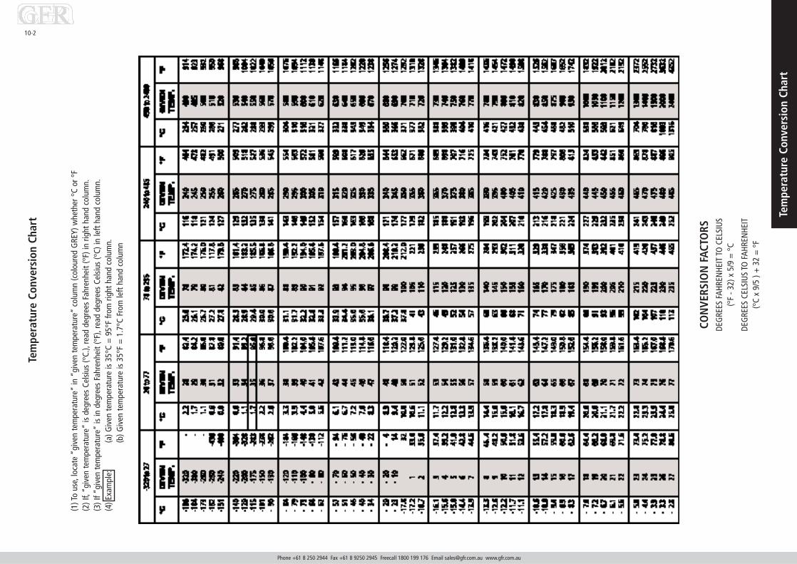
Phone +61 8 250 2944 Fax +61 8 9250 2945 Freecall 1800 199 176 Email [email protected] www.gfr.com.au
Tem
pera
ture
Con
vers
ion
Char
t
10-2
(1) T
o us
e,lo
cate
“gi
ven
tem
pera
ture
”in
“gi
ven
tem
pera
ture
”co
lum
n (c
olou
red
GRE
Y) w
heth
er °
C or
°F
(2) I
f,“g
iven
tem
pera
ture
”is
deg
rees
Cel
sius
(°C.
),re
ad d
egre
es F
ahre
nhei
t (°F
) in
right
han
d co
lum
n.(3
) If “
give
n te
mpe
ratu
re”
is in
deg
rees
Fah
renh
eit (
°F),
read
deg
rees
Cel
sius
(°C)
in le
ft ha
nd c
olum
n.(4
) Exa
mpl
e:(a
) Giv
en te
mpe
ratu
re is
35°
C =
95°
F fro
m ri
ght h
and
colu
mn.
(b) G
iven
tem
pera
ture
is 3
5°F
= 1
.7°C
Fro
m le
ft ha
nd c
olum
n
CON
VERS
ION
FAC
TORS
DEG
REES
FAH
REN
HEIT
TO
CEL
SIU
S (°
F - 3
2) x
5/9
= °
C
DEG
REES
CEL
SIU
S TO
FAH
REN
HEIT
(°C
x 9/
5 ) +
32
= °
F
Tem
pera
ture
Con
vers
ion
Char
t

10-3
Uni
ts a
nd S
ymbo
ls C
onve
rsio
n Ch
art
Uni
ts a
nd S
ymbo
ls C
onve
rsio
n Ch
art
Uni
ts a
nd th
eir s
ymbo
ls fo
r ofte
n us
ed q
uant
ities
Qua
ntit
yN
ame
of u
nit
Uni
t Si
gnSy
mbo
lRe
lati
on a
nd N
otes
(nam
e of
sym
bol)
Mas
s w
eigh
tKi
logr
amKg
mSe
e DI
N 1
305
GVo
lum
eCu
bic
met
res
m_
1 m
3=
100
01lit
res
IV
1 l –
1 d
m3
Forc
eN
ewto
nN
FF
= m
ass
m .
acce
lera
tion
gF
= 1
kg
.9.8
1 m
/s_=
9.81
kgm
/s_
1N
1 k
gm/s
21
kg
9.8
1 N
≈10
N(s
ee a
lso
DIN
130
4)De
nsity
Kilo
gram
sKg
/m_
(rho)
mCu
bic
met
erV
Spec
ific
wei
ght
Kilo
new
ton
KN/m
_γ
(gam
ma)
γ F
= g
.≈
10.
Cubi
c m
eter
VPr
essu
rePa
scal
Pa1
Pa =
1 N
/m_
Bar
Bar
ρ1
bar =
105
PaSp
ecifi
c pr
essu
reN
ewto
nρ
1 N
/mm
_ =
1 M
paM
echa
nica
l str
ess
Squa
re m
illim
etre
N/m
m_
σ(s
igm
a)Te
mpe
ratu
reDe
gree
s Ce
lsiu
s°C
Τ1
°C
1 K
Tem
pera
ture
diff
eren
ceKe
lvin
K∆ϑ
(del
ta th
eta)
∆ϑ=
x [°
C] -
γ[°
C] =
z [K
]En
ergy
E1
J = 1
N .
m =
1 W
.s
Wor
kJo
ule
JA
1 W
= 1
J/s
(W
= W
att)
Heat
qua
ntity
Q1
kcal
= 4
.19
kJ
Dec
imal
par
ts a
nd m
ulti
ples
of
unit
s.Pr
efix
es (e
xcer
pt)
pref
ixna
me
of p
refix
fact
or o
r m
ulti
plie
rµ
mic
ro10
-6=
1
1 00
0 00
0m
mill
i10
-3=
110
00c
cent
i10
-2=
1 100
dde
ci10
-1=
1 10da
deca
101
=10
hhe
cto
102
=10
0k
kilo
103
=10
00m
meg
a10
4=
1 00
0 00
0
Not
e:Fo
r sim
plifi
catio
n pu
rpos
es m
ost o
f the
con
vers
ion
fact
ors
have
bee
nro
unde
d of
f.Th
is le
ads
to a
n in
exac
titud
e of
app
roxi
mat
ely
2%.
This
dev
iatio
n do
es n
ot p
lay
any
role
for
tech
nica
l cal
cula
tions
with
in t
hesc
ope
of th
ese
appl
icat
ion
guid
elin
es.
Conv
ersi
on f
acto
rs f
or c
omm
on u
nits
Uni
tN
/mm
_Pa
bar
m W
Skp
/cm
_
N/m
m_
110
610
100
10
1 Pa
10-6
110
-510
-410
-5
1 ba
r0.
110
51
101
1 m
WS
0.01
104
0.1
10.
1
1 kp
/cm
_0.
110
51
101
=^
=^
=^

Dimensions of Coils20mm to 110mm
Phone +61 8 250 2944 Fax +61 8 9250 2945 Freecall 1800 199 176 Email [email protected] www.gfr.com.au
10-4
Pipe OD Coil OD Coil ID Length mm mm mm Metres
20 1100 600 20025 1200 725 20032 1500 900 20040 1700 1100 15050 2000 1450 15063 2200 1600 10075 2700 1900 10090 2800 2000 60 or 100110 3100 2170 60 or 100
NOTEThe OD of the coils will vary by approximately +/- 100mm due tocoil ovality.The ID of the coils is the minimum measurement. Some variationshould be allowed for due to coil ovality.

Pressure Capacity Above Ground Standard Black PE PipeMaximum mean wall temperature = 65C
Phone +61 8 250 2944 Fax +61 8 9250 2945 Freecall 1800 199 176 Email [email protected] www.gfr.com.au
10-5
This is from actual measured mean wall temperatures at the top of the pipe on Australiansites when the water is not flowing through a pipeline. The Australian Standardsrecommends that the highest operating temperature shall be used as the designtemperature. When the pumps are started the pipeline will be operating at thistemperature until the cooler water has been able to reduce the pipe wall temperatures.This is the actual measured midwall temperature when the pumps are started until theflowing water has cooled the pipe wall.
PN KilopascalsPE80B PE80C PE100
3.2 170 120 1704 210 150 2106.3 330 240 3308 420 300 42010 530 380 52012.5 660 470 65016 840 600 83020 1050 750 104025 1310 935 1300

Pressure Capacity Above Ground with White Co-Ex “Jacket”Maximum mean wall temperature = 35C
Phone +61 8 250 2944 Fax +61 8 9250 2945 Freecall 1800 199 176 Email [email protected] www.gfr.com.au
10-6
The maximum measured mean wall temperature recorded is 35C on the top of the pipeduring summer. This results in increased pressure capacity, reduced thermal movement,increased reliability, and significant cost reduction.
PN KilopascalsPE80B PE80C PE100
3.2 260 230 2604 320 290 3206.3 500 460 5008 640 580 64010 800 730 80012.5 1000 910 100016 1280 1160 128020 1600 1450 160025 2000 1810 2000

Effects of Temperature on Pressure Kilopascals
PE80B
Phone +61 8 250 2944 Fax +61 8 9250 2945 Freecall 1800 199 176 Email [email protected] www.gfr.com.au
10-7
Extrapolation Permissible System Operating Head (m)Temp Limit C Years PN3.2 PN4 PN6.3 PN8 PN10 PN12.5 PN16 PN20
20 200 32 40 63 80 100 125 160 20025 100 30 38 59 75 94 117 150 18830 100 28 35 55 70 88 109 140 17535 100 26 32 50 64 80 100 128 16040 100 24 30 47 60 75 94 120 15045 60 22 28 44 56 70 88 112 14050 36 21 26 41 52 65 81 104 13055 24 19 24 38 48 60 75 96 12060 12 18 23 35 45 56 70 90 11365 8 17 21 33 42 53 66 84 10570 5 16 20 31 39 49 61 78 9875 2 14 18 28 36 45 56 72 9080 2 13 17 26 33 41 52 66 83

10-8Effects of Temperature on PressureKilopascals
PE100
Extrapolation Permissible System Operating Head (m)Temp Limit PN3.2 PN4 PN6.3 PN8 PN10 PN12.5 PN16 PN20 PN25
C Years20 200 32 40 63 80 100 125 160 200 25025 100 30 38 59 75 94 117 150 188 23330 100 28 35 55 70 88 109 140 175 21835 100 26 32 50 64 80 100 128 160 20040 100 24 30 47 60 75 94 120 150 18545 60 22 28 44 56 70 88 112 140 17550 36 21 26 41 52 65 81 104 130 16355 24 19 24 38 48 60 75 96 120 15060 12 18 23 35 45 56 70 90 113 14065 8 17 21 33 42 53 66 84 105 13070 5 16 20 31 39 49 61 78 98 12075 2 14 18 28 36 45 56 72 90 11380 2 13 17 26 33 41 52 66 83 105
NOTE: This table conforms with AS4131.Where the temperature is constant during the life of the pipeline, it is expected to exceed50 years service for temperatures up to 25C. PE100 may be used for applications of 50Cand over.
Phone +61 8 250 2944 Fax +61 8 9250 2945 Freecall 1800 199 176 Email [email protected] www.gfr.com.au

10-9 Pump Suction PipeNegative Pressure Capacity (kPa)
PN Rating PE80B PE80C PE100
3.2 7.4 8.54 15 17 96.3 58 67 188 118 136 73
Note:Polyethylene pipe over PN6.3 can cope with full vacuum. Vacuum is described as zeropressure (minus one atmosphere). The actual vacuum on site varies with barometricpressure for the day.
The negative pressure has been calculated based upon immersion in water at 30C walltemperature. The pipe is assumed to have a 3% ovality.
As polyethylene is less dense than water, the pipe will float on the water surface. The endof the pipe should therefore be inverted to ensure the suction pipe is continuously full ofwater.
Phone +61 8 250 2944 Fax +61 8 9250 2945 Freecall 1800 199 176 Email [email protected] www.gfr.com.au

Polyethylene Flange Connections
Phone +61 8 250 2944 Fax +61 8 9250 2945 Freecall 1800 199 176 Email [email protected] www.gfr.com.au
10-10
Flanges must be installed correctly to ensure damage does not occur during operation.Incorrect installation is the most common cause of flange joint failure. To avoid this, thefollowing procedure should be used:
1. The flange should be assembled to the mating flange prior to welding the stub flangeto the pipeline. If this is not practical the pipeline should be snaked a sufficient distancefrom the joint to ensure the stub can be brought squarely up to the mating flange.
2. The flange assembly must be lifted AT THE PIPE and BROUGHT SQUARELY UP TO TOUCHthe mating flange PRIOR to bolting. Bringing the flanges into contact with the matingflange using the bolts can result in breakage of stub during operation.
3. With the seal lined up, insert all bolts and tighten them until firm taking care not todamage the seal. Washers should be used under all bolts heads and nuts.
4. Tighten the bolts in the following sequence to the following torques. These torquesapply for pressures up to 1000kPa.

Support Distances PE8020mm to 200mm
Phone +61 8 250 2944 Fax +61 8 9250 2945 Freecall 1800 199 176 Email [email protected] www.gfr.com.au
10-11
Size PN4 PN6.3 PN8 PN10 PN12.5 PN16
20 0.5 0.5 0.6 0.6 0.6 0.725 0.5 0.6 0.7 0.7 0.7 0.832 0.6 0.7 0.8 0.8 0.9 0.940 0.7 0.9 0.9 1.0 1.0 1.150 0.9 1.0 1.0 1.1 1.2 1.263 1.0 1.2 1.2 1.3 1.4 1.475 1.1 1.3 1.4 1.5 1.5 1.690 1.3 1.5 1.6 1.7 1.7 1.8110 1.5 1.7 1.8 1.9 2.0 2.1125 1.6 1.8 2.0 2.1 2.2 2.3140 1.7 2.0 2.1 2.2 2.4 2.5160 1.9 2.2 2.3 2.5 2.6 2.7200 2.2 2.5 2.7 2.9 3.0 3.2
NOTE:1. All distances are quoted in metres.2. The support lengths assume a long term deflection of L/360 over more than two spans.
The pipe is assumed to be full of S.G=1 liquid and shielded from solar heating with awhite CO-EX jacket.
3. These distances do not conform with the Australian Standards.4. These distances should be used for gravity due to the deflection.

Support Distances PE80225mm to 1000mm
Phone +61 8 250 2944 Fax +61 8 9250 2945 Freecall 1800 199 176 Email [email protected] www.gfr.com.au
10-12
SIZE PN4 PN6.3 PN8 PN10 PN12.5 PN16
225 2.4 2.7 2.9 3.1 3.3 3.4250 2.6 3.0 3.1 3.3 3.5 3.7280 2.8 3.2 3.4 3.6 3.8 4.0315 3.0 3.4 3.7 3.9 4.1 4.3355 3.3 3.7 4.0 4.2 4.4 4.7400 3.5 4.0 4.3 4.5 4.8 5.0450 3.8 4.4 4.7 4.9 5.2 5.5500 4.1 4.7 5.0 5.3 5.6 5.9560 4.4 5.1 5.4 5.7 6.0 6.0630 4.8 5.5 5.8 6.2 6.5 6.8710 5.2 6.0 6.3 6.7 7.0 7.4800 5.7 6.4 6.9 7.2 7.6 8.01000 6.6 7.5 8.0 8.4 8.9 9.3
NOTE:1 All distances are quoted in metres.2 The support lengths assume a long term deflection of L/360 over more than two spans.
The pipe is assumed to be full of S.G=1 liquid and shielded from solar heating with awhite CO-EX jacket.
3 These distances do not conform with the Australian Standards.4 These distances should not be used for gravity due to the deflection.

Pipe Capacity of Trucks
Phone +61 8 250 2944 Fax +61 8 9250 2945 Freecall 1800 199 176 Email [email protected] www.gfr.com.au
10-13
Pipe OD No of Pipe OD No of mm Pipes mm Pipes
63 45 280 8075 40 315 6390 27 355 50110(100m) 22 400 40110(20m) 450 450 27125 370 500 24140 330 560 19160 250 630 15200 165 710 11225 114 800 9250 99 1000 5
NOTE:These are standard quantities. A well equipped truck may be able to carry more pipes.These quantities may reduce for PN12.5 and above due to weight restrictions of trailers.The capacity of double axle trucks is approx. 18 tonne and approx. 24 tonne for triple axletrucks.

Pipe Bending Radius (metres)20mm to 200mm OD pipe
Phone +61 8 250 2944 Fax +61 8 9250 2945 Freecall 1800 199 176 Email [email protected] www.gfr.com.au
10-14
Nom Size PE80B PE80C,PE100
20 0.4 0.625 0.5 0.832 0.6 1.040 0.8 1.350 1.0 1.663 1.2 2.175 1.5 2.490 1.8 2.9110 2.2 3.6125 2.5 4.1140 2.8 4.6160 3.2 5.2200 4.0 6.6
NOTE:These pipelines bending radii apply at the site ambient temperatures. These radii willreduce as the pipeline’s temperature increases due to solar heating.

Pipe Bending Radius (metres)225mm to 1000mm OD pipe
Phone +61 8 250 2944 Fax +61 8 9250 2945 Freecall 1800 199 176 Email [email protected] www.gfr.com.au
10-15
Nom Size PE80B PE80C,PE100
225 4.5 7.4250 5.0 8.2280 5.6 9.2315 6.3 10.4355 7.1 11.7400 8.0 13.2450 9.0 14.8500 10.0 16.5560 11.2 18.5630 12.6 20.8710 14.2 23.4800 16.0 26.41000 20.0 33.0
NOTE:These pipeline bending radii apply at the site ambient temperatures. These radii willreduce as the pipeline’s temperature increases due to solar heating.
Phone +61 8 250 2944 Fax +61 8 9250 2945 Freecall 1800 199 176 Email [email protected] www.gfr.com.au
10-16Chemical Resistance
The following list has been collated from several sources and is based where possible, on results of actualinstallations. Changes to the composition of the medium or special working conditions could lead todeviations. If in doubt a pilot test should be carried out to confirm compatibility. No guarantees can begiven in respect of the information contained in this list.
CLASSIFICATION
+ Resistant: When installed to this manual or the Australian Standard the mediahas no effect of insignificant effect on the polyethylene pipe.
0 Conditionally Resistant: The medium can cause the pipe to swell. The pressure andtemperature should be restricted and the life of the pipeline limitedtaking expected service into account.
- Not Recommended: This medium should not be used with polyethylene pipe or fittings.
No information: was available where no recommendation has been made.
General effect of chemicals on polyethylene pipe:
Resistant: Water, solutions of inorganic salts, weak acids, strong organic acids,strong alkaline solutions, aliphatic hydrocarbons.
Has limited resistance: Lower alcohols, ester ketones, ethers, aromatic hydrocarbons, mineraloil.
In most cases non-resistant: Light naphtha, fuel mixture.
Completely non-resistant: Unsaturated chlorinated hydrocarbons, turpentine.

Chemical Resistance
Phone +61 8 250 2944 Fax +61 8 9250 2945 Freecall 1800 199 176 Email [email protected] www.gfr.com.au
10-17
Acetaldehyde to Arsenic acidMEDIUM CONCENTRATION 20°C 40°C 60°C
Acetaldehyde technically Pure + 0 0
40%,aqueous solution + + 0
Acetic acid 10%, aqueous + + +
50%, aqueous + + +
technic. pure glacial + 0
Acetic acide anhydride technically pure + 0
Acetone technically pure + + +
Acrylonitrile technically pure + + +
Adipic acid saturated, aqueous + + +
Alcoholic spirits 40%, ethyl alcohol +
Allyl alcohol 96% + + +
Aluminium chloride 10%, aqueous + + +
saturated + + +
Aluminium sulphate 10%, aqueous + + +
cold saturated, aqueous + + +
Ammonia gaseous, tech. pure + + +
Ammonium acetate aqueous + + +
Ammonium carbonate 50%, aqueous + + +
Ammonium chloride 10%, aqueous + + +
cold saturated, aqueous + + +
Ammonium hydrogen fluoride 50%, aqueous + + +
Ammonium hydroxide aqueous, cold saturated + + +
Ammonium nitrate 10%, aqueous + + 0
Ammonium phosphate aqueous + + +
Ammonium sulphide aqueous + + +
Amyl acetate technically pure + + +
Amyl alcohol technically pure + + +
Aniline Technically pure 0
Aniline hydrochloride Aqueous, saturated + + 0
Antimony trichloride 90%, aqueous + + +
Aqua regia -
Arsenic acid 80% aqueous + + +

Phone +61 8 250 2944 Fax +61 8 9250 2945 Freecall 1800 199 176 Email [email protected] www.gfr.com.au
10-18Chemical Resistance
Barium hydroxide to Caustic soda solutionMEDIUM CONCENTRATION 20°C 40°C 60°C
Barium hydroxide Aqueous, saturated + + +
Barium salts aqueous + + +
Beef tallow sulphonated Usual commercial +
Beer Usual commercial + + +
Benzaldehyde Saturated, aqueous + + +
Benzene Technically pure 0 0
Benzine Free of aromatic solvents + + 0
Benzoic acid aqueous + + +
Benzyl alcohol Technically pure + + 0
Borax aqueous + + +
Boric acid aqueous + + +
Brine, sea water + +
Bromine liquid Technically pure -
Bromine vapour High -
Bromine water Saturated, aqueous -
Butadiene Technically pure +
Butane Technically pure +
Butanediol 10% aqueous + + +
Butyl acetate Technically pure +
Butyl phenol, p-tertiary Technically pure 0
Butylene liquid Technically pure -
Butyric acid Technically pure + + 0
Calcium chloride Saturated, aqueous + + +
Calcium hydroxide Aqueous, saturated + + +
Calcium hypochlorite Cold saturated, aqueous + + +
Calcium nitrate 50%, aqueous + + +
Carbon dioxide Tech pure, anhydrous + + +
Tech pure, moist + + +
Carbon disulphide Techically pure 0
Carbon tetrachloride Techically pure -
Caustic potash solution 50%, aqueous + + +
Caustic soda solution 10%, aqueous + + +
40%, aqueous + + +

Chemical Resistance
Phone +61 8 250 2944 Fax +61 8 9250 2945 Freecall 1800 199 176 Email [email protected] www.gfr.com.au
10-19
Caustic acid to Chrome alumMEDIUM CONCENTRATION 20°C 40°C 60°C
Caustic acid 50%, aqueous + + +
Chloral hydrate Technically pure + + +
Chlorethanol Technically pure + + +
Cholic acid 10%, aqueous + +
20%, aqueous 0
Chlorine Moist, 97% gaseous -
Anhydrous, tech. pure 0 0 -
Liquid, technically pure -
Chlorine water saturated 0 0
Chloroacetic acid, 50% aqueous + + +
Technically pure + + +
Chlorobenzene Technically pure
Chloroform Technically pure -
Chlorosulphonic acid Technically pure -
Chrome alum Cold saturated, aqueous + + +
Chromic acid 50% aqueous 0 -
All, aqueous 0
+Sulphuric acid + water -
Cider +
Citric acid 10%, aqueous + + +
20%, aqueous 0
Chlorine Moist, 97% gaseous -
Anhydrous, tech. pure 0 0 -
Liquid, technically pure -
Chlorine water Saturated 0 0
Chloroacetic acid, 50%, aqueous + + +
Technically pure + + +
Chlorobenzene Technically pure 0
Chloroform Technically pure -
Chlorosulphonic acid Technically pure -
Chrome alum Cold saturated, aqueous + + +

Chemical Resistance
Phone +61 8 250 2944 Fax +61 8 9250 2945 Freecall 1800 199 176 Email [email protected] www.gfr.com.au
10-20
Chromic acid to Ethyl acetateMEDIUM CONCENTRATION 20°C 40°C 60°C
Chromic acid 50%, aqueous 0 -
All, aqueous 0
+Sulphuric acid + water -
Cider +
Citric acid 10%, aqueous + + +
Compressed air Containing oil + +
Copper salts All, aqueous + + +
Corn oil Technically pure + + 0
Cresol Cold saturated, aqueous + +
Crotonic aldhyde Technically pure +
Cyanide (sodium) Technically pure + + +
Cyclohexane Technically pure + + +
Cyclohexanol Technically pure + + +
Cyclohexanone Technically pure + 0 0
Detergents As washing lather + + +
Dextrine Usual commercial + + +
Dibutyl ether Technically pure 0
Dibutyl phthalate Technically pure + 0 0
Dibutyle sebacate Technically pure +
Dichloroacetic acid 50%, aqueous + + +
Technically pure + + 0
Dichlorobenzene Technically pure 0
Dichloroethylene Technically pure -
Diesel oil + 0 0
Diglycolic acid 30%, aqueous + + +
Di-isobutyl ketone Technically pure + -
Dimethyl formamide Technically pure + + 0
Dimethylamine Technically pure + 0
Dinonyl Phthalate Technically pure 0
Dioxane Technically pure + + +
Escaid 110® 55°C 0
Ethyl acetate Technically pure + 0 0

Chemical Resistance
Phone +61 8 250 2944 Fax +61 8 9250 2945 Freecall 1800 199 176 Email [email protected] www.gfr.com.au
10-21
Ethyl alcohol to Hydrobromic acidMEDIUM CONCENTRATION 20°C 40°C 60°C
Ethyl alcohol 96%, technically pure + + +
+acetic acid, tech. pure + + +
Ethyl chloride Technically pure 0
Ethyl ether Technically pure 0
Ethylene chloride Technically pure 0
Ethylene diamine Technically pure + + +
Ethylene glycol Technically pure + + +
Ethylene oxide Tech. Pure, liquid -
Fatty acids > C6 Technically pure + + 0
Fatty alcoholsulphonate aqueous + + +
Fertilizer salts aqueous + + +
Fluorine Technically pure -
Fluosilicic acid 32%, aqueous + + +
Formaldehyde 40%, aqueous + + +
Formamide Technically pure + + +
Formic acid 50%, aqueous + + +
Technically pure + + +
Frigen 12® Technically pure -
Fruit juices + + +
Fruit pukp + + +
Fuel oil 0 -
Furfuryl alcohol Technically pure + + +
Gelatine All, aqueous + + +
Glucose All. aqueous + + +
Gylcerine Technically pure + + +
All aqueous + + +
Gylcocoll 10%, aqueous + +
Glycolic acid 40% aqueous + + +
Heptane Technically pure + 0
Hexane Technically pure + 0
Hydrazine hydrate aqueous + + +
Hydrobromic acid Aqueous, 50% + + +

Chemical Resistance
Phone +61 8 250 2944 Fax +61 8 9250 2945 Freecall 1800 199 176 Email [email protected] www.gfr.com.au
10-22
Hydrochloric acid to Methyl acetateMEDIUM CONCENTRATION 20°C 40°C 60°C
Hydrochloric acid 36%, aqueous + + +
Hydrocyanic acid Technically pure + + +
Hydrofluoric acid 50%, aqueous + + 0
70%, aqueous + 0
Hydrogen Technically pure + + +
Hydrogen chloride Technic, pure, gaseous + + +
Hydrogen peroxide 30%, aqueous + + +
90%, aqueous + -
Hydrogen sulphide Technically pure + + 0
Saturated, aqueous + + +
Hydroxylamine sul- All, aqueous + + +
Iodine Solution 6.5% iodine in ethanol + 0
Iron salts All, aqueous + + +
Iso-octane Technically pure + 0
Isopropyl alcohol Technically pure + + +
Isopropyl ether Technically pure 0 -
Lactic acid 10%, aqueous + + +
Lanolin Technically pure + + +
Linseed oil Technically pure + + +
Liqueurs + +
Lix 84-1® 30% v/v 55°C 0
Lead acetate Aqueous, saturated + + +
Lubricating oils + + 0
Lubricating oils Free of aromatic solvents + + 0
Magnesium salts All, aqueous + + +
Maleic acid Cold saturated, aqueous + + +
Marmelade + + +
Mercury pure + + +
Mercury salts Cold saturated, aqueous + + +
Methane (natural gas) Technically pure +
Methanol All + + +
Methyl acetate Technically pure +

Chemical Resistance
Phone +61 8 250 2944 Fax +61 8 9250 2945 Freecall 1800 199 176 Email [email protected] www.gfr.com.au
10-23
Methyl amine to Palm oilMEDIUM CONCENTRATION 20°C 40°C 60°C
Methyl amine 30% aqueous +
Methyl bromide Technically pure 0
Methyl chloride Technically pure 0
Methylene chloride Technically pure 0
Methyl ethyl ketone Technically pure + 0 -
Milk + + +
Mineral water + + +
Molasses + + +
Molasses wort + + +
Monochloroacetic acid Technically pure + + +
Morpholin Technically pure + + +
Mowilith D Usual commercial +
Naphthalene Technically pure + 0
Nickel salts Cold saturated, aqueous + + +
Nitric acid 6%, aqueous + + +
40%, aqueous 0 -
65%, aqueous 0 - -
100% -
Nitrobenzene Technically pure + + 0
Nitrotoluene Technically pure + + 0
Nitrous oxide Dilute, moist, anhydrous + + +
Oleic acid Technically pure + + 0
Oleum 10% (sulphate) -
Oleum vapours traces -
Olive oil + + 0
Orform SX-7® Solvent extr diluent 70°C 0
Oxalic acid Cold saturated, aqueous + + +
Oxygen Technically pure + + 0
Ozone 2% in air 0 -
Cold saturated, aqueous 0 -
Palmitic acid Technically pure 0
Palm oil, palm nut oil + + 0

Chemical Resistance
Phone +61 8 250 2944 Fax +61 8 9250 2945 Freecall 1800 199 176 Email [email protected] www.gfr.com.au
10-24
Paraffin emulsions to Potassium nitrateMEDIUM CONCENTRATION 20°C 40°C 60°C
Paraffin emulsions Usual commercial + + 0
Paraffin Oil + + +
Perchloric acid 10%, aqueous + + +
70%, aqueous + 0 -
Perchloroethylene Technically pure 0
Petroleum Technically pure + + 0
Petroleum ether Technically pure + 0 0
Petroleum jelly Technically pure 0 -
Phenol 10%, aqueous + + 0
Phenylhydrazine Technically pure 0
Phosgene Liquid, technically pure 0
Phosphoric acid 50%, aqueous + + +
85%, aqueous + + 0
Phosphorous chlorides Trichloride, tech. pure + 0
Pentachloride, tech, pure
Oxychloride, Tech, pure + 0
Phosphorous pentoxide Technically pure + +
Phthalic acid Saturated, aqueous + + +
Picric acid 1%, aqueous +
Potassium sulphates 50%, aqueous + + +
Potassium bichromate Saturated, aqueous + + +
Potassium borate 10%, aqueous + + +
Potassium bromate Cold saturated, aqueous + + 0
Potassium bromide All, aqueous + + +
Potassium carbonate Cold saturated, aqueous + +
Potassium chlorate Cold saturated, aqueous + + +
Potassium chloride All, aqueous + + +
Potassium chromate Cold saturated, aqueous +
Potassium cyanide Cold saturated, aqueous + + +
Potassium hydroxide 50%, aqueous + + +
Potassium iodine Cold saturated, aqueous + + +
Potassium nitrate 50%, aqueous + + +

Chemical Resistance
Phone +61 8 250 2944 Fax +61 8 9250 2945 Freecall 1800 199 176 Email [email protected] www.gfr.com.au
10-25
Potassium perchlorate to Sodium hypochloriteMEDIUM CONCENTRATION 20°C 40°C 60°C
Potassium perchlorate Cold saturated, aqueous + + +
Potassium permanga- Cold saturated, aqueous + + 0
Potassium persulphate All, aqueous + + +
Potassium sulphate All, aqueous + + +
Propane Technically pure, liquid +
Technically pure, gase - +
Propanol, n– and iso- Technically pure + + +
Propargyl alcohol 7%, gaseous + + +
Propionic acid 50%, aqueous + + +
Propylene glycol Technically pure + + +
Propylene oxide Technically pure +
Pyidine Technically pure + 0 0
Shellsol 2046® Diluent, degreaser + 0
Silicone oil + + +
Silver salts Cold saturated, aqueous + + +
Soap solutions All, aqueous + + +
Sodium acetate All, aqueous + + +
Sodium benzoate Cold saturated, aqueous + + +
Sodium bicarbonate Cold saturated, aqueous + + +
Sodium bisulpate 10%, aqueous + + +
Sodium bisulphite All, aqueous + + +
Sodium bromate All, aqueous + 0
Sodium bromide All, aqueous + + +
Sodium carbonate Cold saturated, aqueous + + +
Sodium chlorate All, aqueous + + +
Sodium chloride All, aqueous + + +
Sodium chlorite Diluted, aqueous +
Sodium chromate Diluted, aqueous +
Sodium disulphite All, aqueous +
Sodium dithionite 10%, aqueous + + +
Sodium Fluoride Cold saturated, aqueous +
Sodium hypochlorite 12.5% active chloride 0 -

Chemical Resistance
Phone +61 8 250 2944 Fax +61 8 9250 2945 Freecall 1800 199 176 Email [email protected] www.gfr.com.au
10-26
Sodium iodide to TetrachloroethaneMEDIUM CONCENTRATION 20°C 40°C 60°C
Sodium iodide All, aqueous +
Sodium nitrate Cold saturated, aqueous + + +
Sodium nitrite Cold saturated, aqueous +
Sodium oxalate Cold saturated. aqueous +
Sodium persulphate Cold saturated, aqueous + + +
Sodium phosphate Cold saturated, aqueous + + +
Sodium silicate All, aqueous + + +
Sodium sulphate Cold saturated, aqueous + + +
Sodium sulphide Cold saturated, aqueous + + +
Sodium sulphite Cold saturated, aqueous + + +
Sodium thiosulphate Cold saturated, aqueous + + +
Spindle oil 0 0
Stannous chloride Cold saturated, aqueous + + +
Starch solution All, aqueous + + +
Starch syrup Usual commercial + + +
Stearic acid Technically pure + 0
Succinic acid All, aqueous + + +
Sugar syrup Usual commercial + + +
sulphur Technically pure + + +
Sulphur dioxide All, anhydrous, moist + + +
Sulphur dioxide Technically pure, liquid -
Sulphur trioxide -
Sulphuric acid 60%, aqueous + + +
80%, aqueous + + 0
90%, aqueous 0
96%, aqueous -
Sulphyrous acid Saturated, aqueous + + +
Sulphuryl chloride Technically pure -
tallow Technically pure + + +
Tannic acid All, aqueous + + +
Tartaric acid All, aqueous + + +
Tetrachloroethane Technically pure 0

Chemical Resistance
Phone +61 8 250 2944 Fax +61 8 9250 2945 Freecall 1800 199 176 Email [email protected] www.gfr.com.au
10-27
Tetrahydrofurane to Zinc SaltsMEDIUM CONCENTRATION 20°C 40°C 60°C
Tetrohydrofurane Technically pure 0
Tetrahydronapthalene Technically pure 0
Thionyl chloride Technically pure -
Toluene Technically pure 0 -
Tributylphosphate Technically pure + + +
Trichloroethylene Technically pure + 0 -
Trichloroaecetic acid Technically pure + 0 -
50%, aqueous + + +
Trichloroethane Technically pure 0
Tricresyl phosphate Technically pure + + +
Triethanolamine Technically pure + + +
Trioctyl phosphate Technically pure 0
Turpentine oil Technically pure 0 0 0
Urea 30%, aqueous + + +
Urine + + +
Wax alcohol Technically pure 0 -
Wetting agents 5%, aqueous +
Yeast, all aqueous + + +
Xylene Technically pure - - -
Zinc salts All, aqueous + + +
® Registered Trademark or product name

Flow Nomogram
Phone +61 8 250 2944 Fax +61 8 9250 2945 Freecall 1800 199 176 Email [email protected] www.gfr.com.au
10-28

INDEX

Index
Phone +61 8 9250 2944 Fax +61 8 9250 2945 Freecall 1800 199 176 Email [email protected] www.gfr.com.au
11-1
ADAPTORS
Male/Female with male B.S.P. thread extended for Electrofusion 3-5Compression Male 4-7Compression Female 4-8
BACKING PLATE/RING
Table D sizing 5-1Table E sizing 5-2ANSI sizing 5-3Blind flange 5-4
BENDS
Short Radius 2-1Sweep: extended for Electrofusion & Butt Welding 30º & 45º 2-2Sweep: extended for Electrofusion & Butt Welding 60º & 90º 2-3Segmented: for Butt Welding 30 º, 45 º 60 º & 90 º 2-4
BUSHES
Threaded 4-13
CAPS
Extended for Electrofusion 3-4Threaded 4-13
COUPLINGS
Electrofusion 3-1Compression 4-3Compression Reducing 4-3Compression repair 4-3Compression flanged Coupling 4-8Supraclamp 5-9Supraclamp 5-10Stainless Steel repair full circle 5-11Stainless Steel repair half circle 5-11Stainless Steel repair junior 5-12
ELBOWS
Extended for Electrofusion 45º & 90º 3-3Compression 4-6Compression with Male offtake 4-6Compression with Female offtake 4-6Compression 45º 4-7Compression 45º with Male offtake 4-7Threaded 4-12
Index
Phone +61 8 9250 2944 Fax +61 8 9250 2945 Freecall 1800 199 176 Email [email protected] www.gfr.com.au
11-2
NIPPLES
Threaded 4-13
O-RINGS
Nitrile 4-9Viton 4-9EPDM 4-9
PIPE
PE Pipe Dimensions 1-1Pipe Dimensions 1-2PE Wall Thickness Comparison Guide 1-3Non-pressure Pipe 6-1Pressure Pipe 6-2Vinyl Iron Pipe 6-3Bore casing 6-3Drain Coil 9-1Green Pipe-recycled 9-5Tiran Dripper 9-6Tiran Dripper 9-7
PLUGS
Compression End Plug 4-9Threaded 4-13
REDUCERS
Concentric and Eccentric for Butt Welding 2-10Concentric and Eccentric for Butt Welding 2-11Extended for Electrofusion 3-7
RODS
Polypropylene Weld Rod 2-14Polyethylene Weld Rod 2-14Polypropylene Solid Rod 2-14Polyethylene Solid Rod 2-14
SHEETS
HDPE Flat Black 2-13Polypropylene Flat 2-13

Index
Phone +61 8 9250 2944 Fax +61 8 9250 2945 Freecall 1800 199 176 Email [email protected] www.gfr.com.au
11-3
SHOULDERED ENDS
Butt Weld 2-12
SLOTTING
PVC Horizontal 9-2PVC Longitudinal 9-3PVC Windows 9-4
SOCKETS
Threaded 4-12
SPECIALISED FABRICATIONS
Cyclone overflows 8-4Flow meters 8-4Machine Guards 8-6
SPLIT RINGS
Acetal 4-10C-PVC 4-10PP Insert 4-10
STRAINERS
Suction Strainers 8-5
STUB FLANGES
Injection Moulded for Butt Welding 2-12Extended for Electrofusion 3-2
TANKS
Chemical Tanks 8-1Chemical Tanks 8-2Tank Enquiry Form 8-3
TAPPING SADDLES/BANDS
Single Tapping Saddle for rural and metric 4-11Metric 4-11Tapping bands 5-13Tapping bands 5-14

Index
Phone +61 8 9250 2944 Fax +61 8 9250 2945 Freecall 1800 199 176 Email [email protected] www.gfr.com.au
11-4
TECHNICAL INFORMATION
PE Pipe Dimensions 1-1Pipe Dimensions 1-2PE Wall Thickness Comparison Guide 1-3Pressure De-rating 2-15Flange Bolting Table for Table D 5-5Flange Bolting Table for PE & Steel Table D 5-6Flange Bolting Table for Table E 5-7Flange Bolting Table for PE & Steel Table E 5-8uPVC pressure pipe and fittings 6-4uPVC pressure pipe and fittings jointing instructions 6-6uPVC pressure pipe and fittings jointing instructions 6-7Coverage of solvent cements for PVC jointing 6-8PVC elevated service temperatures 6-8PVC thermal linear expansion 6-8Pressure-stress conversion chart 10-1Temperature conversion chart 10-2Units and symbols 10-3Dimensions of coils 20mm – 110mm 10-4Pressure Capacity Above Ground Standard Black PE Pipe 10-5Pressure Capacity Above Ground with White Co-Ex ‘Jacket’ 10-6Effects of temperature on pressure PE80B 10-7Effects of temperature on pressure PE100 10-8Pump Suction Pipe - negative pressure capacity 10-9PE flange connections – torque chart 10-10Support distances PE80 – 20mm – 200mm 10-11Support distances PE80 – 225mm – 1000mm 10-12Pipe capacity of trucks 10-13Pipe bending radius 10-14Pipe bending radius 10-15Chemical resistance A – Z 10-16Flow nomogram chart 10-28
TEES
Injection Moulded for Butt Welding 2-5Reducing Injection Moulded for Butt Welding 2-6Reducing fabricated for Butt Welding 2-7Welded for Butt Welding 2-8Junctions for Butt Welding 2-9Extended for Electrofusion 3-6Compression 4-4Compression Reducing 4-4Compression with Male offtake 4-4Compression Reducing with Female offtake 4-5Compression with Female Offtake 4-5Threaded 4-12

Index
Phone +61 8 9250 2944 Fax +61 8 9250 2945 Freecall 1800 199 176 Email [email protected] www.gfr.com.au
11-5
VALVES
Master valves 7-2Vent Master valves 7-3Vent Master valves 7-4Check Master valves 7-5Check Master valves 7-6Float Master 7-7Float Master 7-8Ball Valve PVC 7-11Ball Valve Brass 7-11Gate Valve tested 7-12Gate Valve Brass 7-12Butterfly Valve 7-12Butterfly Valve spaces 7-13

Phone +61 8 9250 2944 Fax +61 8 9250 2945 Freecall 1800 199 176 Email [email protected] www.gfr.com.au
From design through to installation of finished product,GFR services all industries including :-
• Mining• Utilities• Civil Engineering• Industrial• Oil & Gas• Agriculture

8 Artello Bay Road Midvale Western Australia 6056Phone: (08) 9250 2944Facsimile: (08) 9250 2945Freecall: 1800 199 176Email: [email protected] : www.gfr.com.au
www.gfr.com.au