getz equipment innovators dry chemical fill system
TRANSCRIPT
Getz Equipment InnovatorsDry Chemical Fill System
This manual covers the following part numbers:
3G0050/3G0050 M/3G0050 OPT/3G0050 OPTM - 100# ABC Filling Systems
3G0031/3G0031 M/3G0031 OPT/3G0031 OPTM - 150# ABC Filling Systems
3G0032/3G0032 M/3G0032 OPT/3G0032 OPTM - 150# BC Filling Systems
3G0086/3G0086 M/3G0086 OPT/3G0086 OPTM - Industrial Fill Systems
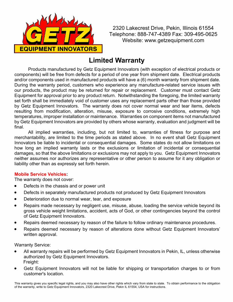
2320 Lakecrest Drive, Pekin, Illinois 61554Telephone: 888-747-4389 Fax: 309-495-0625
Website: www.getzequipment.com
Limited WarrantyProducts manufactured by Getz Equipment Innovators (with exception of electrical products or
components) will be free from defects for a period of one year from shipment date. Electrical productsand/or components used in manufactured products will have a (6) month warranty from shipment date.During the warranty period, customers who experience any manufacture-related service issues withour products, the product may be returned for repair or replacement. Customer must contact GetzEquipment for approval prior to any product return. Notwithstanding the foregoing, the limited warrantyset forth shall be immediately void of customer uses any replacement parts other than those providedby Getz Equipment Innovators. The warranty does not cover normal wear and tear items, defectsresulting from modification, alteration, misuse, exposure to corrosive conditions, extremely hightemperatures, improper installation or maintenance. Warranties on component items not manufacturedby Getz Equipment Innovators are provided by others whose warranty, evaluation and judgment will befinal. All implied warranties, including, but not limited to, warranties of fitness for purpose andmerchantability, are limited to the time periods as stated above. In no event shall Getz EquipmentInnovators be liable to incidental or consequential damages. Some states do not allow limitations onhow long an implied warranty lasts or the exclusions or limitation of incidental or consequentialdamages, so that the above limitations or exclusions may not apply to you. Getz Equipment Innovatorsneither assumes nor authorizes any representative or other person to assume for it any obligation orliability other than as expressly set forth herein.
Mobile Service Vehicles:The warranty does not cover:· Defects in the chassis and or power unit· Defects in separately manufactured products not produced by Getz Equipment Innovators· Deterioration due to normal wear, tear, and exposure· Repairs made necessary by negligent use, misuse, abuse, loading the service vehicle beyond its
gross vehicle weight limitations, accident, acts of God, or other contingencies beyond the control of Getz Equipment Innovators.
· Repairs deemed necessary by reason of the failure to follow ordinary maintenance procedures.· Repairs deemed necessary by reason of alterations done without Getz Equipment Innovators’
written approval.
Warranty Service:· All warranty repairs will be performed by Getz Equipment Innovators in Pekin, IL, unless otherwise
authorized by Getz Equipment Innovators. Freight:· Getz Equipment Innovators will not be liable for shipping or transportation charges to or from
customer's location.
This warranty gives you specific legal rights, and you may also have other rights which vary from state to state. To obtain performance to the obligationof the warranty, write to Getz Equipment Innovators, 2320 Lakecrest Drive, Pekin IL 61554, USA for instructions.
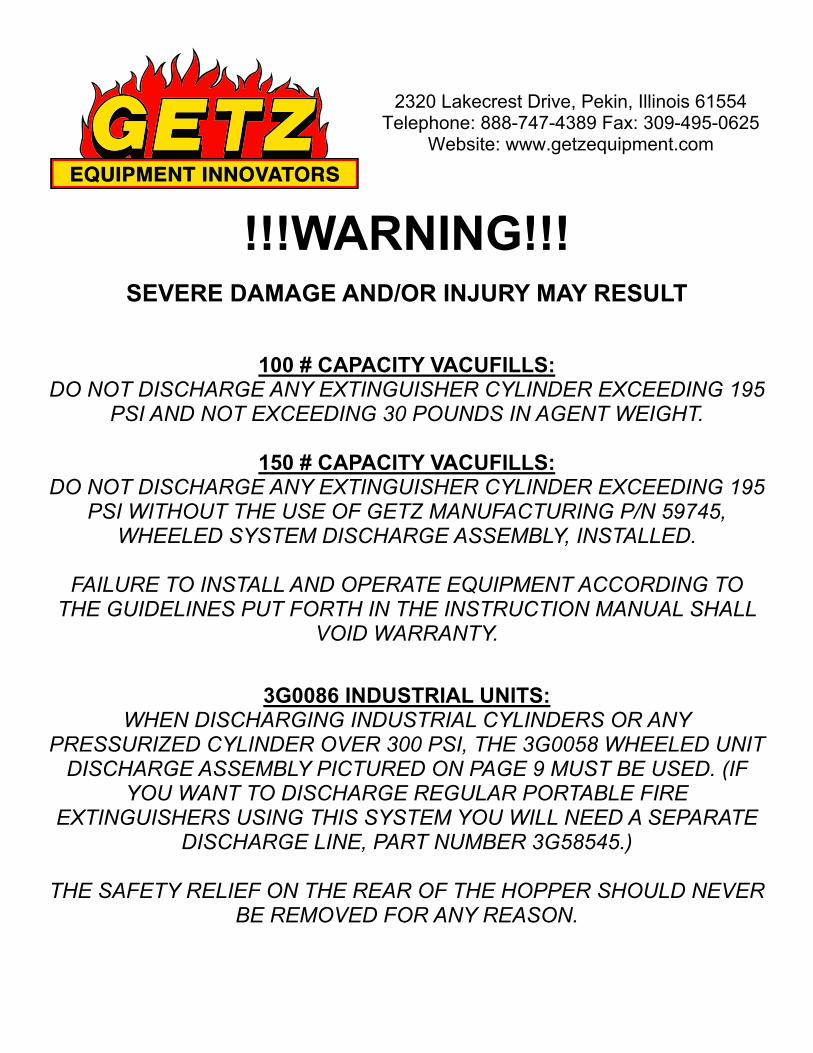
!!!WARNING!!!SEVERE DAMAGE AND/OR INJURY MAY RESULT
100 # CAPACITY VACUFILLS:DO NOT DISCHARGE ANY EXTINGUISHER CYLINDER EXCEEDING 195
PSI AND NOT EXCEEDING 30 POUNDS IN AGENT WEIGHT.
150 # CAPACITY VACUFILLS:DO NOT DISCHARGE ANY EXTINGUISHER CYLINDER EXCEEDING 195
PSI WITHOUT THE USE OF GETZ MANUFACTURING P/N 59745,WHEELED SYSTEM DISCHARGE ASSEMBLY, INSTALLED.
FAILURE TO INSTALL AND OPERATE EQUIPMENT ACCORDING TOTHE GUIDELINES PUT FORTH IN THE INSTRUCTION MANUAL SHALL
VOID WARRANTY.
3G0086 INDUSTRIAL UNITS:WHEN DISCHARGING INDUSTRIAL CYLINDERS OR ANY
PRESSURIZED CYLINDER OVER 300 PSI, THE 3G0058 WHEELED UNITDISCHARGE ASSEMBLY PICTURED ON PAGE 9 MUST BE USED. (IF
YOU WANT TO DISCHARGE REGULAR PORTABLE FIREEXTINGUISHERS USING THIS SYSTEM YOU WILL NEED A SEPARATE
DISCHARGE LINE, PART NUMBER 3G58545.)
THE SAFETY RELIEF ON THE REAR OF THE HOPPER SHOULD NEVERBE REMOVED FOR ANY REASON.
2320 Lakecrest Drive, Pekin, Illinois 61554Telephone: 888-747-4389 Fax: 309-495-0625
Website: www.getzequipment.com
Getz Equipment Innovators Dry Chemical Fill System
Table of Contents
Page
4 ................................................... Getz Filling System5 ................................................... Fill System Exterior Parts - Drawing 16 ................................................... Exterior Control Console Parts - Drawing 27 ................................................... Standard Control Console Parts - Drawing 38 ................................................... Optimum Control Console Parts - Drawing 49 ................................................... Discharge Assembly - Drawing 510 .................................................. Fill Line Assembly - Drawing 611 ................................................... Assembly Instructions12 ................................................... Procedure for Discharging Fire Extinguisher12 .................................................. Procedure for Filling Fire Extinguisher13 .................................................. Trouble Shooting & Service Aids14 ................................................... Recommended Spare Parts Kit15 ................................................... Maintenance Kit Instructions

Getz Equipment Innovators Dry Chemical Fill System
Air Source:
Air CompressorCompressed AirNitrogen
To get maximum vacuum on your fill system, the operating input pressure may range from 40 to 65P.S.I. This setting will vary depending on which console you purchased (standard or optimum),atmosphere conditions and chemical composition.
To set your regulator for the best results, take the vacuum line off of the elbow connector screwedinto the filler tube. Turn the on-off switch on and put your finger over the vacuum line. Then, adjustthe regulator up or down as needed, so that you have maximum vacuum on your gauge.
Warning: Operator must wear safety glasses when operating filling system equipment
4
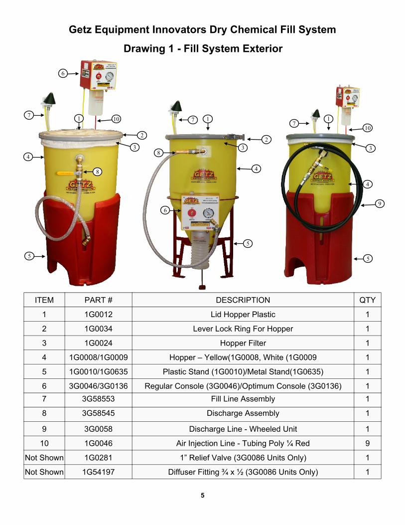
Getz Equipment Innovators Dry Chemical Fill System
Drawing 1 - Fill System Exterior
ITEM PART # DESCRIPTION QTY
1 1G0012 Lid Hopper Plastic 1
2 1G0034 Lever Lock Ring For Hopper 1
3 1G0024 Hopper Filter 1
4 1G0008/1G0009 Hopper – Yellow(1G0008, White (1G0009 1
5 1G0010/1G0635 Plastic Stand (1G0010)/Metal Stand(1G0635) 1
6 3G0046/3G0136 Regular Console (3G0046)/Optimum Console (3G0136) 17 3G58553 Fill Line Assembly 1
8 3G58545 Discharge Assembly 1
9 3G0058 Discharge Line - Wheeled Unit 1
10 1G0046 Air Injection Line - Tubing Poly ¼ Red 9
Not Shown 1G0281 1” Relief Valve (3G0086 Units Only) 1
Not Shown 1G54197 Diffuser Fitting ¾ x ½ (3G0086 Units Only) 1
5
1
23
4
5
6
7
84
1
2
3
5
6
7
8
1010
71
3
4
5
9

Getz Equipment Innovators Dry Chemical Fill System
Drawing 2 - Control Console Exterior
ITEM PART # DESCRIPTION QTY
1 1G0015 Toggle Valve 3 Way 1
2 1G0018 Gauge 30” Vacuum 2” Dial 1
3 1G0023/1G0125 Control Console Plastic Box/Lid 1
4 1G54318 Hose Barb Plastic ½ x ¼ Female 1
5 1G0067 Jar Filter 1
6 1G0206 Filter Cap 1
7 1G0020 Jar Plastic Ribbed 1
8 3G0082 Push Button Valve Air Injection w/Cover 1
9 1G0207 Stem 1
10 1G0197 Bulkhead Union ¼ - ¼ Tube 2
11 1G0205 Jar Gasket 1
6
2
1
3
4
5
6 7
8
9
10
1011
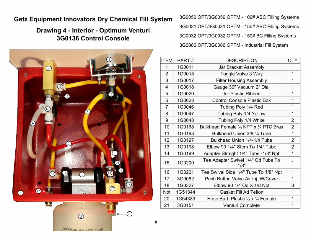
ITEM PART # DESCRIPTION QTY1 1G0011 Jar Bracket Assembly 12 1G0015 Toggle Valve 3 Way 13 1G0017 Filter Housing Assembly 14 1G0018 Gauge 30" Vacuum 2" Dial 15 1G0020 Jar Plastic Ribbed 16 1G0023 Control Console Plastic Box 17 1G0032 Tubing 1/2 I.D. Clear Vinyl Per Ft. 18 1G0041 Clamp 2 - Ear 3/4" 19 1G0046 Tubing Poly 1/4 Red 2
10 1G0047 Tubing Poly 1/4 Yellow 211 1G0048 Tubing Poly 1/4 White 112 1G0099 Elbow Poly Barbed 1/2 X 1/2 113 1G0193 Bulkhead Union 3/8-1/4 Tube,M20.Ox1.5 Th 114 1G0197 Bulkhead Union 1/4-1/4 Tube 215 1G0198 Elbow 90 1/4" Stem To 1/4" Tube 216 1G0199 Adapter Straight 1/4" Tube -1/8" Npt 117 1G0200 Tee Adapter Swivel 1/4" Od Tube To 1/8" 118 1G0201 Tee Swivel Side 1/4" Tube To 1/8" Npt 119 3G0082 Push Button Valve Air Inj. W/Cover 120 1G0327 Elbow 90 1/4 Od X 1/8 Npt 221 1G54318 Barb Hose Plas 1/2 X 3/9 Ml 122 1G54319 Barb Hose Plastic 1/2 X 3/8 Female� 123 3G0151 Venturi Complete 1
Getz Equipment Innovators Dry Chemical Fill System
Drawing 3 - Interior - Standard Venturi3G0046 Control Console
3G0050/3G0050 M - 100# ABC Filling Systems
3G0031/3G0031 M - 150# ABC Filling Systems
3G0032/3G0032 M - 150# BC Filling Systems
3G0086/3G0086 M - Industrial Fill System
1622
11
5
2
8
3
9
10 7
7
4
1
6
12
13
14
14
15 15
17
18
1920
21
21 23
7
8
ITEM PART # DESCRIPTION QTY1 1G0011 Jar Bracket Assembly 12 1G0015 Toggle Valve 3 Way 13 1G0017 Filter Housing Assembly 14 1G0018 Gauge 30" Vacuum 2" Dial 15 1G0020 Jar Plastic Ribbed 16 1G0023 Control Console Plastic Box 17 1G0046 Tubing Poly 1/4 Red 18 1G0047 Tubing Poly 1/4 Yellow 19 1G0048 Tubing Poly 1/4 White 2
10 1G0168 Bulkhead Female ¼ NPT x ¼ PTC Bras 211 1G0193 Bulkhead Union 3/8-¼ Tube 112 1G0197 Bulkhead Union 1/4-1/4 Tube 213 1G0198 Elbow 90 1/4" Stem To 1/4" Tube 214 1G0199 Adapter Straight 1/4" Tube -1/8" Npt 1
15 1G0200 Tee Adapter Swivel 1/4" Od Tube To1/8" 1
16 1G0201 Tee Swivel Side 1/4" Tube To 1/8" Npt 117 3G0082 Push Button Valve Air Inj. W/Cover 118 1G0327 Elbow 90 1/4 Od X 1/8 Npt 3Not 1G51344 Gasket Fill Ad Teflon 120 1G54339 Hose Barb Plastic ½ x ¼ Female 121 3G0151 Venturi Complete 1
Getz Equipment Innovators Dry Chemical Fill System
Drawing 4 - Interior - Optimum Venturi3G0136 Control Console
3G0050 OPT/3G0050 OPTM - 100# ABC Filling Systems
3G0031 OPT/3G0031 OPTM - 150# ABC Filling Systems
3G0032 OPT/3G0032 OPTM - 150# BC Filling Systems
3G0086 OPT/3G0086 OPTM - Industrial Fill System
16
21
11
5
2
8
3
9
10
7
4
1
6
13 14
15
17
18
20
12
18
18

Getz Equipment Innovators Dry Chemical Fill System
Drawing 5 - Discharge Assembly
ITEM PART # DESCRIPTION QTY
1 1G0028 Coupling Female Straight Thru ¼ 1
2 1G0033 Tubing ½ Reinforced Clear Vinyl 4
3 1G0041 Clamp 2 - EAR ¼ 2
4 1G0075 Barb Hose ½ MNPT x ½ Hose 1
5 1G0076 Barb Hose ¼ MNPT x ½ Hose 1
6 1G0077 Elbow Brass 90 Degree ½ NPT 1
7 1G0078 Elbow Brass 45 Degree Street ¼ 1
8 1G0084 Valve Ball ½ Brass 1
9 1G51686 Pipe Reducer Brass ¾ x ½ 1
5 6
2
3
8
4
7
1
9
3
9
ITEM PART # DESCRIPTION QTY
1 1G0258 Ball Valve 1/2 Female X FemaleVented 1
2 1G0260 1/2" Male Socket 2
3 1G0578 Coupling 1/2 F/F 5000 Psi 2
4 1G51253 Coupling 1/2 Male Synflex 2
5 1G51562 Hose Synflex 1/2 2000psi 8
6 1G51674 Coupling Q/C 1/2 Male 2
3G58545 Standard Discharge Assembly
3G0058 Wheeled Unit Discharge Assembly
5
62
4
1
362
4
3

Getz Equipment Innovators Dry Chemical Fill System
Drawing 6 - 3G58553 Fill Line Assembly
ITEM PART # DESCRIPTION QTY
1 1G0032 Tubing ½ ID Clear Vinyl 8
2 1G0048 Tubing Poly ¼ White 7
3 1G0091 Rubber Fill Cone Brass Filler Tube 1
4 3G0014 Filler Tube Assembly Aluminum 1
5 1G0237 Moisture Cap Filler Tube 1
10
1
2
4
3
5
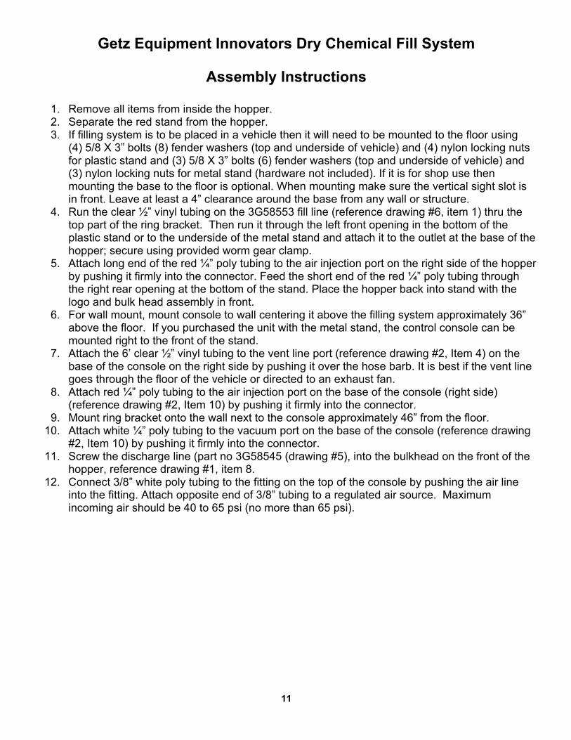
Getz Equipment Innovators Dry Chemical Fill System
1. Remove all items from inside the hopper.2. Separate the red stand from the hopper.3. If filling system is to be placed in a vehicle then it will need to be mounted to the floor using
(4) 5/8 X 3” bolts (8) fender washers (top and underside of vehicle) and (4) nylon locking nutsfor plastic stand and (3) 5/8 X 3” bolts (6) fender washers (top and underside of vehicle) and(3) nylon locking nuts for metal stand (hardware not included). If it is for shop use thenmounting the base to the floor is optional. When mounting make sure the vertical sight slot isin front. Leave at least a 4” clearance around the base from any wall or structure.
4. Run the clear ½” vinyl tubing on the 3G58553 fill line (reference drawing #6, item 1) thru thetop part of the ring bracket. Then run it through the left front opening in the bottom of theplastic stand or to the underside of the metal stand and attach it to the outlet at the base of thehopper; secure using provided worm gear clamp.
5. Attach long end of the red ¼” poly tubing to the air injection port on the right side of the hopperby pushing it firmly into the connector. Feed the short end of the red ¼” poly tubing throughthe right rear opening at the bottom of the stand. Place the hopper back into stand with thelogo and bulk head assembly in front.
6. For wall mount, mount console to wall centering it above the filling system approximately 36”above the floor. If you purchased the unit with the metal stand, the control console can bemounted right to the front of the stand.
7. Attach the 6’ clear ½” vinyl tubing to the vent line port (reference drawing #2, Item 4) on thebase of the console on the right side by pushing it over the hose barb. It is best if the vent linegoes through the floor of the vehicle or directed to an exhaust fan.
8. Attach red ¼” poly tubing to the air injection port on the base of the console (right side)(reference drawing #2, Item 10) by pushing it firmly into the connector.
9. Mount ring bracket onto the wall next to the console approximately 46” from the floor.10. Attach white ¼” poly tubing to the vacuum port on the base of the console (reference drawing
#2, Item 10) by pushing it firmly into the connector.11. Screw the discharge line (part no 3G58545 (drawing #5), into the bulkhead on the front of the
hopper, reference drawing #1, item 8.12. Connect 3/8” white poly tubing to the fitting on the top of the console by pushing the air line
into the fitting. Attach opposite end of 3/8” tubing to a regulated air source. Maximumincoming air should be 40 to 65 psi (no more than 65 psi).
Assembly Instructions
11
Getz Equipment Innovators Dry Chemical Fill System
1. Make sure extinguisher is pressurized.2. If extinguisher is not pressurized and is full/partially full of chemical, hook up re-charge
adapter and pressurize to factory recommended pressure on gauge.3. Remove hose and connect correct discharge adapter with male quick coupler into valve
assembly of extinguisher.4. Connect discharge assembly to the discharge adapter on extinguisher.5. Ensure that powder recovery lid is clamped firmly to hopper.6. Close valve and partially discharge extinguisher into the discharge hose to inspect chemical.7. If chemical is proper chemical for extinguisher being discharged, open valve to allow chemical
into hopper and allow nitrogen pressure to escape through the powder recovery filter.8. Discharge extinguisher and when pressure gauge reaches zero, disconnect discharge
assembly hose and inspect or hydro-test the extinguisher.9. Remove valve from extinguisher and clean.
10. Perform 6 year internal maintenance, recharge or hydro-test.
Portable Extinguisher Discharge Instructions
1. Ensure that scale is set and balanced to zero.2. Visually check with inspection light that empty dry chemical extinguisher is dry and not
corroded.3. Check for type of chemical to be filled on label of empty extinguisher.4. Take clear fill line and extend it to the top of the empty cylinder to be filled.5. Place rubber cone (from the end of fill line) into top of cylinder neck with a clockwise ¼ turn.6. With extinguisher and fill line attached on scale, return scale back to zero (making it
“weightless”) and then fill to recommended weight.7. Turn off-on valve to “ON” position until extinguisher reaches recommended weight. Turn valve
to “OFF” once it is filled. **If chemical returns to plastic jar before reaching correct weight, let itsettle then turn valve back on to reach desired weight.
8. Remove fill line from neck to fill line ring bracket.
Filling Empty Dry Chemical Extinguisher Instructions
12
View Video for discharge/refill here: https://www.youtube.com/watch?v=ytMx9HLIqQ8&t=4s
Getz Equipment Innovators Dry Chemical Fill System
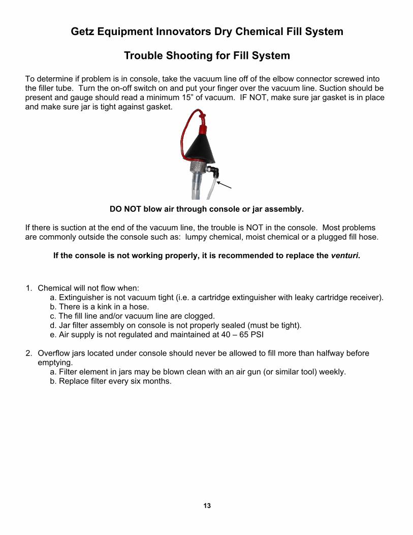
To determine if problem is in console, take the vacuum line off of the elbow connector screwed intothe filler tube. Turn the on-off switch on and put your finger over the vacuum line. Suction should bepresent and gauge should read a minimum 15” of vacuum. IF NOT, make sure jar gasket is in placeand make sure jar is tight against gasket.
DO NOT blow air through console or jar assembly.
If there is suction at the end of the vacuum line, the trouble is NOT in the console. Most problemsare commonly outside the console such as: lumpy chemical, moist chemical or a plugged fill hose.
If the console is not working properly, it is recommended to replace the venturi.
Trouble Shooting for Fill System
1. Chemical will not flow when:a. Extinguisher is not vacuum tight (i.e. a cartridge extinguisher with leaky cartridge receiver).b. There is a kink in a hose.c. The fill line and/or vacuum line are clogged.d. Jar filter assembly on console is not properly sealed (must be tight).e. Air supply is not regulated and maintained at 40 – 65 PSI
2. Overflow jars located under console should never be allowed to fill more than halfway beforeemptying.
a. Filter element in jars may be blown clean with an air gun (or similar tool) weekly. b. Replace filter every six months.
13
Getz Equipment Innovators Dry Chemical Fill System
Recommended MaintenanceGetz Equipment Innovators has designed their plastic dry chemical fill systems to be the most
maintenance-free available and to provide the longest equipment life. Nevertheless all equipmentneeds maintained and simple steps can be done to assure your fill system(s) continues to operate atoptimum performance. To maintain optimum fill system performance we recommend the followingmaintenance items at a minimum. These recommendations are based on averages so frequencies
may vary depending on number of extinguishers serviced using the dry chemical fill system(s).
Daily- Empty the plastic overflow jar when dry chemical reaches the line marked on the jar. Allowing thedry chemical to go above the line on the jar will allow chemical to flow back into the console tubing
causing damage to the venturi, on/off valve, and vacuum gauge.
Weekly- Clean Hopper Lid Filter. Vacuum the inside of the filter. If there is dry chemical caked onto the filter
is needs to be replaced.- Clean Jar Filter. Use only 10-15 psi to blow and clean the jar filter.
- Discharge Hose. Look for burn/soft spot at end by coupling and replace when worn
Annually- Replace Hopper Lid Filter
- Replace Jar Filter- Replace Jar Gasket
- Replace Venturi
14
Getz Equipment Innovators Dry Chemical Fill System
Maintenance Kit Instructions
1G0024 - Hopper Lid Filter1. Unlatch the hopper lever lock ring and remove with the plastic hopper lid.2. Remove old hopper lid filter and discard.3. Install new hopper lid filter and reinstall plastic hopper lid (beveled edge on top) and lever lock
ring.
1G0067 – Jar Filter & 1G0205 – Jar Gasket4. Unscrew the Plastic Jar counterclockwise from the bottom of the console and the metal Filter
Cap. The Jar Filter should be loose to remove after the metal Filter Cap is removed.5. Remove the old Jar Gasket. Gently clean the Filter Housing Assembly being careful not to
blow air up into the Housing/Console that will force chemical into the tubing.6. Install the new Jar Gasket and new Jar Filter with the metal Filter Cap. Install the Plastic Jar.
3G0151 – Venturi (Standard Units Only)1. Remove the four corner screws on the front console lid to access the inside.2. Remove vent line from the poly elbow.3. Use a 7/16” open end wrench to remove the two brass nuts and pull the clear and yellow ¼”
tubing with those brass nuts from the venturi.4. Unscrew (counterclockwise) the brass nut using the ear clamp. This will leave the nut in the
vent tube and the piece of ¼” clear plastic tube.5. Remove the brass nut on the new venturi that has the piece of ¼” clear plastic tubing. The ¼”
clear plastic tubing can be removed from the new venturi if the same tubing stayed in the venttube.
6. Install the new venturi into the brass nut that was left in the vent tube.7. Remove the other two brass nuts in the new venturi.8. Insert ¼” clear and yellow tubing and tighten brass nuts.9. Insert vent line into the poly elbow.10. Replace front Console lid and tighten four corner screws.
15
View Maintenance Video: https://www.youtube.com/watch?v=WDXCNaJ1Ud4&t=236s
Maintenance Kits
3G0089 - Maintenance Kit for 100/150 Standard Units:(Covers 3G0050/3G0050 M / 3G0031/3G0031 M / 3G0032/3G0032 M / 3G0086/3G0086 M)
3G0175 - Maintenance Kit for 100/150 Optimum Units:(Covers 3G0050 OPT/3G0050 OPTM / 3G0031 OPT/3G0031 OPTM / 3G0032 OPT/3G0032 OPTM/ 3G0086 OPT/3G0086 OPTM)