get control, inc. e84 handheld tester gci05001 …getcontrol.com/downloads/hht_user_manual.pdfget...
TRANSCRIPT

Get Control, Inc.
E84 Handheld TesterGCI05001
Users Manual
Rev 3.2a April 12, 2011

Table of Contents
Introduction . . . . . . . . . . . . . . . . . . . . . . . . . . . . . . . . . . . . . . . . . . . . . . . . . . . . . . . . . . . . . . . . . . . . . . 1
Making Rear Panel Connections . . . . . . . . . . . . . . . . . . . . . . . . . . . . . . . . . . . . . . . . . . . . . . . . . . . . . 1Passive E84 Port . . . . . . . . . . . . . . . . . . . . . . . . . . . . . . . . . . . . . . . . . . . . . . . . . . . . . . . . . . . . . 1Active E84 Port . . . . . . . . . . . . . . . . . . . . . . . . . . . . . . . . . . . . . . . . . . . . . . . . . . . . . . . . . . . . . 1COM Port . . . . . . . . . . . . . . . . . . . . . . . . . . . . . . . . . . . . . . . . . . . . . . . . . . . . . . . . . . . . . . . . . . 1
Navigating The E84 HHT Menus . . . . . . . . . . . . . . . . . . . . . . . . . . . . . . . . . . . . . . . . . . . . . . . . . . . . . . . 2Using The Soft Keys . . . . . . . . . . . . . . . . . . . . . . . . . . . . . . . . . . . . . . . . . . . . . . . . . . . . . . . . . . 2
Paperless Storage System (PSS) . . . . . . . . . . . . . . . . . . . . . . . . . . . . . . . . . . . . . . . . . . . . . . . . . . . . . . . 2SD Card Interface . . . . . . . . . . . . . . . . . . . . . . . . . . . . . . . . . . . . . . . . . . . . . . . . . . . . . . . . . . . 2Internal SD Card . . . . . . . . . . . . . . . . . . . . . . . . . . . . . . . . . . . . . . . . . . . . . . . . . . . . . . . . . . . . 2SD Card Format . . . . . . . . . . . . . . . . . . . . . . . . . . . . . . . . . . . . . . . . . . . . . . . . . . . . . . . . . . . . . 3File Organization . . . . . . . . . . . . . . . . . . . . . . . . . . . . . . . . . . . . . . . . . . . . . . . . . . . . . . . . . . . . 3
Tool ID . . . . . . . . . . . . . . . . . . . . . . . . . . . . . . . . . . . . . . . . . . . . . . . . . . . . . . . . . . . . . . 3Test Results File Name . . . . . . . . . . . . . . . . . . . . . . . . . . . . . . . . . . . . . . . . . . . . . . . . . 3
Tool ID File Format . . . . . . . . . . . . . . . . . . . . . . . . . . . . . . . . . . . . . . . . . . . . . . . . . . . . . . . . . . . 4Saving Test Results . . . . . . . . . . . . . . . . . . . . . . . . . . . . . . . . . . . . . . . . . . . . . . . . . . . . . . . . . . . 4Editing Tool Details . . . . . . . . . . . . . . . . . . . . . . . . . . . . . . . . . . . . . . . . . . . . . . . . . . . . . . . . . . 5
Main Test Menu . . . . . . . . . . . . . . . . . . . . . . . . . . . . . . . . . . . . . . . . . . . . . . . . . . . . . . . . . . . . . . . . . . . 6
Active Mode Load and Unload Cycles . . . . . . . . . . . . . . . . . . . . . . . . . . . . . . . . . . . . . . . . . . . . . . . . . 6
Electrical Tests . . . . . . . . . . . . . . . . . . . . . . . . . . . . . . . . . . . . . . . . . . . . . . . . . . . . . . . . . . . . . . . . . . . . 8Power Supply Voltage Test . . . . . . . . . . . . . . . . . . . . . . . . . . . . . . . . . . . . . . . . . . . . . . . . . . . . 8Displaying Signal Voltage and Current Levels . . . . . . . . . . . . . . . . . . . . . . . . . . . . . . . . . . . . . 8Electrical Test Manual Mode . . . . . . . . . . . . . . . . . . . . . . . . . . . . . . . . . . . . . . . . . . . . . . . . . . 9
IR Transceiver Test . . . . . . . . . . . . . . . . . . . . . . . . . . . . . . . . . . . . . . . . . . . . . . . . . . . . . . . . . . . . . . . . . 9IR Transceiver Auto Test Screen . . . . . . . . . . . . . . . . . . . . . . . . . . . . . . . . . . . . . . . . . . . . . . . 10IR Test Summary Screen . . . . . . . . . . . . . . . . . . . . . . . . . . . . . . . . . . . . . . . . . . . . . . . . . . . . . 10IR Error Detail Screen . . . . . . . . . . . . . . . . . . . . . . . . . . . . . . . . . . . . . . . . . . . . . . . . . . . . . . . 11IR Test Manual Mode . . . . . . . . . . . . . . . . . . . . . . . . . . . . . . . . . . . . . . . . . . . . . . . . . . . . . . . 11IR On / OFF State Levels . . . . . . . . . . . . . . . . . . . . . . . . . . . . . . . . . . . . . . . . . . . . . . . . . . . . . . 12
Manual Mode Control . . . . . . . . . . . . . . . . . . . . . . . . . . . . . . . . . . . . . . . . . . . . . . . . . . . . . . . . . . . . . 12Manual Control Screen . . . . . . . . . . . . . . . . . . . . . . . . . . . . . . . . . . . . . . . . . . . . . . . . . . . . . 12
Interface to DLD . . . . . . . . . . . . . . . . . . . . . . . . . . . . . . . . . . . . . . . . . . . . . . . . . . . . . . . . . . . . . . . . . . 13DLD Live Mode . . . . . . . . . . . . . . . . . . . . . . . . . . . . . . . . . . . . . . . . . . . . . . . . . . . . . . . . . . . . . 14DLD Log File . . . . . . . . . . . . . . . . . . . . . . . . . . . . . . . . . . . . . . . . . . . . . . . . . . . . . . . . . . . . . . . 14
HOWTO: Download the DLD Log - Step by Step Instructions . . . . . . . . . . . . . . . . . . . 15DLD Configuration Screen . . . . . . . . . . . . . . . . . . . . . . . . . . . . . . . . . . . . . . . . . . . . . . . . . . . 15
Update DLD Configuration . . . . . . . . . . . . . . . . . . . . . . . . . . . . . . . . . . . . . . . . . . . . . 16
Stored Test Data . . . . . . . . . . . . . . . . . . . . . . . . . . . . . . . . . . . . . . . . . . . . . . . . . . . . . . . . . . . . . . . . . . 16Stored Test Data File List . . . . . . . . . . . . . . . . . . . . . . . . . . . . . . . . . . . . . . . . . . . . . . . . . . . . . 17File Management Options . . . . . . . . . . . . . . . . . . . . . . . . . . . . . . . . . . . . . . . . . . . . . . . . . . . 18
Configuring The Tester . . . . . . . . . . . . . . . . . . . . . . . . . . . . . . . . . . . . . . . . . . . . . . . . . . . . . . . . . . . . . 19Setting Time & Date . . . . . . . . . . . . . . . . . . . . . . . . . . . . . . . . . . . . . . . . . . . . . . . . . . . . . . . . . 19
Setting E84 Timeout Values . . . . . . . . . . . . . . . . . . . . . . . . . . . . . . . . . . . . . . . . . . . . . . . . . . . 19Setting Power Timeouts . . . . . . . . . . . . . . . . . . . . . . . . . . . . . . . . . . . . . . . . . . . . . . . . . . . . . . 20Setting Default Communications Method . . . . . . . . . . . . . . . . . . . . . . . . . . . . . . . . . . . . . . . 20Setting Screen Contrast . . . . . . . . . . . . . . . . . . . . . . . . . . . . . . . . . . . . . . . . . . . . . . . . . . . . . 21Storing Configuration Settings . . . . . . . . . . . . . . . . . . . . . . . . . . . . . . . . . . . . . . . . . . . . . . . . 21
Charging the Rechargeable Battery Pack . . . . . . . . . . . . . . . . . . . . . . . . . . . . . . . . . . . . . . . . . . . . . 22
HHT Firmware Field Update . . . . . . . . . . . . . . . . . . . . . . . . . . . . . . . . . . . . . . . . . . . . . . . . . . . . . . . . . 22Field Update Errors . . . . . . . . . . . . . . . . . . . . . . . . . . . . . . . . . . . . . . . . . . . . . . . . . . . . . . . . . 23Field Update Details . . . . . . . . . . . . . . . . . . . . . . . . . . . . . . . . . . . . . . . . . . . . . . . . . . . . . . . . 23Field Update Verification . . . . . . . . . . . . . . . . . . . . . . . . . . . . . . . . . . . . . . . . . . . . . . . . . . . . 24Field Update Progress . . . . . . . . . . . . . . . . . . . . . . . . . . . . . . . . . . . . . . . . . . . . . . . . . . . . . . . 24
Emulator Test Suite Addendum . . . . . . . . . . . . . . . . . . . . . . . . . . . . . . . . . . . . . . . . . . . . . . . . . . . . . . 25
Overview . . . . . . . . . . . . . . . . . . . . . . . . . . . . . . . . . . . . . . . . . . . . . . . . . . . . . . . . . . . . . . . . . . . . . . . 27HHT to UUT Connection . . . . . . . . . . . . . . . . . . . . . . . . . . . . . . . . . . . . . . . . . . . . . . . . . . . . . . 27
Running the HHT Test Suite . . . . . . . . . . . . . . . . . . . . . . . . . . . . . . . . . . . . . . . . . . . . . . . . . . . . . . . . . . 28
Continuing an Emulator Test Suite . . . . . . . . . . . . . . . . . . . . . . . . . . . . . . . . . . . . . . . . . . . . . . . . . . . . 28
HHT Test Suite Help System . . . . . . . . . . . . . . . . . . . . . . . . . . . . . . . . . . . . . . . . . . . . . . . . . . . . . . . . . . 29
Active Mode Test Plan . . . . . . . . . . . . . . . . . . . . . . . . . . . . . . . . . . . . . . . . . . . . . . . . . . . . . . . . . . . . . 31Active Mode Static Tests . . . . . . . . . . . . . . . . . . . . . . . . . . . . . . . . . . . . . . . . . . . . . . . . . . . . . 31
Active Mode Static Test A . . . . . . . . . . . . . . . . . . . . . . . . . . . . . . . . . . . . . . . . . . . . . . 31Active Mode Static Test B . . . . . . . . . . . . . . . . . . . . . . . . . . . . . . . . . . . . . . . . . . . . . . 31Active Mode Static Test C . . . . . . . . . . . . . . . . . . . . . . . . . . . . . . . . . . . . . . . . . . . . . 31
Active Mode Functionality Tests . . . . . . . . . . . . . . . . . . . . . . . . . . . . . . . . . . . . . . . . . . . . . . . 31Active Mode Functionality Test A . . . . . . . . . . . . . . . . . . . . . . . . . . . . . . . . . . . . . . . . 31Active Mode Functionality Test B . . . . . . . . . . . . . . . . . . . . . . . . . . . . . . . . . . . . . . . . 32Active Mode Functionality Test C . . . . . . . . . . . . . . . . . . . . . . . . . . . . . . . . . . . . . . . 33Active Mode Functionality Test C - 2nd Run . . . . . . . . . . . . . . . . . . . . . . . . . . . . . . . . 34Active Mode Functionality Test D . . . . . . . . . . . . . . . . . . . . . . . . . . . . . . . . . . . . . . . . 35Active Mode Functionality Test D - 2nd Run . . . . . . . . . . . . . . . . . . . . . . . . . . . . . . . . 36Active Mode Functionality Test E . . . . . . . . . . . . . . . . . . . . . . . . . . . . . . . . . . . . . . . . 37Active Mode Functionality Test F . . . . . . . . . . . . . . . . . . . . . . . . . . . . . . . . . . . . . . . . 38Active Mode Functionality Test G . . . . . . . . . . . . . . . . . . . . . . . . . . . . . . . . . . . . . . . 39Active Mode Functionality Test H . . . . . . . . . . . . . . . . . . . . . . . . . . . . . . . . . . . . . . . . 40Active Mode Functionality Test I . . . . . . . . . . . . . . . . . . . . . . . . . . . . . . . . . . . . . . . . 41Active Mode Functionality Test J . . . . . . . . . . . . . . . . . . . . . . . . . . . . . . . . . . . . . . . . 42Active Mode Functionality Test K . . . . . . . . . . . . . . . . . . . . . . . . . . . . . . . . . . . . . . . . 43Active Mode Functionality Test L . . . . . . . . . . . . . . . . . . . . . . . . . . . . . . . . . . . . . . . . 44Active Mode Functionality Test M . . . . . . . . . . . . . . . . . . . . . . . . . . . . . . . . . . . . . . . 45Active Mode Functionality Test N . . . . . . . . . . . . . . . . . . . . . . . . . . . . . . . . . . . . . . . . 46Active Mode Functionality Test O . . . . . . . . . . . . . . . . . . . . . . . . . . . . . . . . . . . . . . . 47Active Mode Functionality Test P . . . . . . . . . . . . . . . . . . . . . . . . . . . . . . . . . . . . . . . . 48Active Mode Functionality Test Q . . . . . . . . . . . . . . . . . . . . . . . . . . . . . . . . . . . . . . . 49
HHT Test Suite Results . . . . . . . . . . . . . . . . . . . . . . . . . . . . . . . . . . . . . . . . . . . . . . . . . . . . . . . . . . . . . . 50
Emulator Test Suite Worksheet . . . . . . . . . . . . . . . . . . . . . . . . . . . . . . . . . . . . . . . . . . . . . . . . . . . . . . . 51

HHT Test Suite Worksheet . . . . . . . . . . . . . . . . . . . . . . . . . . . . . . . . . . . . . . . . . . . . . . . . . . . . . . . . . . . 53Active Mode Static Tests . . . . . . . . . . . . . . . . . . . . . . . . . . . . . . . . . . . . . . . . . . . . . . . . . . . . . 53Active Mode Functionality Tests . . . . . . . . . . . . . . . . . . . . . . . . . . . . . . . . . . . . . . . . . . . . . . . 53

List of Figures
Figure 1 - HHT Rear Panel . . . . . . . . . . . . . . . . . . . . . . . . . . . . . . . . . . . . . . . . . . . . . . . . . . . . . . . . . . . . 1Figure 2 - Soft Keys and Icons . . . . . . . . . . . . . . . . . . . . . . . . . . . . . . . . . . . . . . . . . . . . . . . . . . . . . . . . 2Figure 3 - Example SD Card File System . . . . . . . . . . . . . . . . . . . . . . . . . . . . . . . . . . . . . . . . . . . . . . . . . 3Figure 4 - Stored Test Results Files . . . . . . . . . . . . . . . . . . . . . . . . . . . . . . . . . . . . . . . . . . . . . . . . . . . . . . 3Figure 5 - Tool ID File Format . . . . . . . . . . . . . . . . . . . . . . . . . . . . . . . . . . . . . . . . . . . . . . . . . . . . . . . . . 4Figure 6 - Save Test Results Screen . . . . . . . . . . . . . . . . . . . . . . . . . . . . . . . . . . . . . . . . . . . . . . . . . . . . . 4Figure 7 - Edit Tool Details Screen . . . . . . . . . . . . . . . . . . . . . . . . . . . . . . . . . . . . . . . . . . . . . . . . . . . . . 5Figure 8 - Edit Tool Details Screen (2) . . . . . . . . . . . . . . . . . . . . . . . . . . . . . . . . . . . . . . . . . . . . . . . . . . . 5Figure 9 - Main Test Menu . . . . . . . . . . . . . . . . . . . . . . . . . . . . . . . . . . . . . . . . . . . . . . . . . . . . . . . . . . . 6Figure 10 - Standard Cycle Test Menu . . . . . . . . . . . . . . . . . . . . . . . . . . . . . . . . . . . . . . . . . . . . . . . . . . 6Figure 11 - Active Mode Load Cycle - Internal IR . . . . . . . . . . . . . . . . . . . . . . . . . . . . . . . . . . . . . . . . . 7Figure 12 - External IR Connection . . . . . . . . . . . . . . . . . . . . . . . . . . . . . . . . . . . . . . . . . . . . . . . . . . . . . 7Figure 13 - Direct Connection . . . . . . . . . . . . . . . . . . . . . . . . . . . . . . . . . . . . . . . . . . . . . . . . . . . . . . . . 7Figure 14 - Load Cycle Graph Window . . . . . . . . . . . . . . . . . . . . . . . . . . . . . . . . . . . . . . . . . . . . . . . . . 7Figure 15 - Load Cycle Complete . . . . . . . . . . . . . . . . . . . . . . . . . . . . . . . . . . . . . . . . . . . . . . . . . . . . . 7Figure 16 - Power Supply Voltage Test . . . . . . . . . . . . . . . . . . . . . . . . . . . . . . . . . . . . . . . . . . . . . . . . . . 8Figure 17 - Active Signal Levels Screen - Voltage . . . . . . . . . . . . . . . . . . . . . . . . . . . . . . . . . . . . . . . . . 8Figure 18 - Active Signal Levels - Current . . . . . . . . . . . . . . . . . . . . . . . . . . . . . . . . . . . . . . . . . . . . . . . . 8Figure 19 - Electrical Test - Manual Mode . . . . . . . . . . . . . . . . . . . . . . . . . . . . . . . . . . . . . . . . . . . . . . . 9Figure 20 - IR Transceiver Test . . . . . . . . . . . . . . . . . . . . . . . . . . . . . . . . . . . . . . . . . . . . . . . . . . . . . . . . . 9Figure 21 - IR Transceiver Test Alignment . . . . . . . . . . . . . . . . . . . . . . . . . . . . . . . . . . . . . . . . . . . . . . . . 9Figure 22 - IR Auto Test Active . . . . . . . . . . . . . . . . . . . . . . . . . . . . . . . . . . . . . . . . . . . . . . . . . . . . . . . 10Figure 23 - IR Auto Test with Errors . . . . . . . . . . . . . . . . . . . . . . . . . . . . . . . . . . . . . . . . . . . . . . . . . . . . . 10Figure 24 - IR Transceiver Test Summary Screen . . . . . . . . . . . . . . . . . . . . . . . . . . . . . . . . . . . . . . . . . 10Figure 25 - IR Error Detail Screen . . . . . . . . . . . . . . . . . . . . . . . . . . . . . . . . . . . . . . . . . . . . . . . . . . . . . 11Figure 26 - IR Error Detail Screen . . . . . . . . . . . . . . . . . . . . . . . . . . . . . . . . . . . . . . . . . . . . . . . . . . . . . 11Figure 27 - IR Test Manul Mode . . . . . . . . . . . . . . . . . . . . . . . . . . . . . . . . . . . . . . . . . . . . . . . . . . . . . . 11Figure 28 - IR Test ‘On’ Measurements . . . . . . . . . . . . . . . . . . . . . . . . . . . . . . . . . . . . . . . . . . . . . . . . . 12Figure 29 - Manual Control Menu . . . . . . . . . . . . . . . . . . . . . . . . . . . . . . . . . . . . . . . . . . . . . . . . . . . . 12Figure 30 - Manual Control - Active Mode . . . . . . . . . . . . . . . . . . . . . . . . . . . . . . . . . . . . . . . . . . . . . . 12Figure 31 - Interface to DLD Main Screen . . . . . . . . . . . . . . . . . . . . . . . . . . . . . . . . . . . . . . . . . . . . . . 13Figure 32 - Interface to DLD - Attempting to Connect . . . . . . . . . . . . . . . . . . . . . . . . . . . . . . . . . . . . . 13Figure 33 - Interface to DLD - Contact Established . . . . . . . . . . . . . . . . . . . . . . . . . . . . . . . . . . . . . . . 14Figure 34 - DLD Live Mode Display . . . . . . . . . . . . . . . . . . . . . . . . . . . . . . . . . . . . . . . . . . . . . . . . . . . . 14Figure 35 - DLD Log File Upload Screen . . . . . . . . . . . . . . . . . . . . . . . . . . . . . . . . . . . . . . . . . . . . . . . . 14Figure 36 - DLD Log Upload Completed . . . . . . . . . . . . . . . . . . . . . . . . . . . . . . . . . . . . . . . . . . . . . . . 15Figure 37 - DLD Configuration Screen . . . . . . . . . . . . . . . . . . . . . . . . . . . . . . . . . . . . . . . . . . . . . . . . . 15Figure 38 - Update DLD Configuration . . . . . . . . . . . . . . . . . . . . . . . . . . . . . . . . . . . . . . . . . . . . . . . . . 16Figure 39 - Stored Test Data Menu . . . . . . . . . . . . . . . . . . . . . . . . . . . . . . . . . . . . . . . . . . . . . . . . . . . . 16Figure 40 - Delete Tool Warning . . . . . . . . . . . . . . . . . . . . . . . . . . . . . . . . . . . . . . . . . . . . . . . . . . . . . . 16Figure 41 - Stored Test Data - Marked Records . . . . . . . . . . . . . . . . . . . . . . . . . . . . . . . . . . . . . . . . . . 17Figure 42 - Delete File Warning . . . . . . . . . . . . . . . . . . . . . . . . . . . . . . . . . . . . . . . . . . . . . . . . . . . . . . 17Figure 43 - Upload Complete Message . . . . . . . . . . . . . . . . . . . . . . . . . . . . . . . . . . . . . . . . . . . . . . . . 18Figure 44 - Tester Configuration - Time & Date . . . . . . . . . . . . . . . . . . . . . . . . . . . . . . . . . . . . . . . . . . 19Figure 45 - Tester Configuration - E84 Timeouts . . . . . . . . . . . . . . . . . . . . . . . . . . . . . . . . . . . . . . . . . . 19Figure 46 - Tester Configuration - Power Settings . . . . . . . . . . . . . . . . . . . . . . . . . . . . . . . . . . . . . . . . . 20Figure 47 - Tester Configuration - Comm Method . . . . . . . . . . . . . . . . . . . . . . . . . . . . . . . . . . . . . . . . 20Figure 48 - Tester Configuration - Contrast . . . . . . . . . . . . . . . . . . . . . . . . . . . . . . . . . . . . . . . . . . . . . . 21Figure 49 - Charging the HHT . . . . . . . . . . . . . . . . . . . . . . . . . . . . . . . . . . . . . . . . . . . . . . . . . . . . . . . . 22Figure 50 - Charge Battery Screen . . . . . . . . . . . . . . . . . . . . . . . . . . . . . . . . . . . . . . . . . . . . . . . . . . . . 22Figure 51 - Field Update Screen . . . . . . . . . . . . . . . . . . . . . . . . . . . . . . . . . . . . . . . . . . . . . . . . . . . . . . 23Figure 52 - Field Update Error Screen . . . . . . . . . . . . . . . . . . . . . . . . . . . . . . . . . . . . . . . . . . . . . . . . . . 23Figure 53 - Field Update Detail Screen . . . . . . . . . . . . . . . . . . . . . . . . . . . . . . . . . . . . . . . . . . . . . . . . 23

Figure 54 - Confirm HHT Update Screen . . . . . . . . . . . . . . . . . . . . . . . . . . . . . . . . . . . . . . . . . . . . . . . . 24Figure 55 - Loading HHT Update . . . . . . . . . . . . . . . . . . . . . . . . . . . . . . . . . . . . . . . . . . . . . . . . . . . . . 24Figure 56 - Writing Update to Internal Flash . . . . . . . . . . . . . . . . . . . . . . . . . . . . . . . . . . . . . . . . . . . . . 24Figure 57 - Standard Cycle Test Menu . . . . . . . . . . . . . . . . . . . . . . . . . . . . . . . . . . . . . . . . . . . . . . . . . 28Figure 58 - Select EM Test Results Screen 1 . . . . . . . . . . . . . . . . . . . . . . . . . . . . . . . . . . . . . . . . . . . . . 28Figure 59 - Select EM Test Results Screen 2 . . . . . . . . . . . . . . . . . . . . . . . . . . . . . . . . . . . . . . . . . . . . . 28Figure 60 - Help File Format . . . . . . . . . . . . . . . . . . . . . . . . . . . . . . . . . . . . . . . . . . . . . . . . . . . . . . . . . 29Figure 61 - Example Help System File . . . . . . . . . . . . . . . . . . . . . . . . . . . . . . . . . . . . . . . . . . . . . . . . . . 30Figure 62 - Tester Configuration Menu . . . . . . . . . . . . . . . . . . . . . . . . . . . . . . . . . . . . . . . . . . . . . . . . . 31Figure 63 - Power Supply Voltage Test Screen . . . . . . . . . . . . . . . . . . . . . . . . . . . . . . . . . . . . . . . . . . . 32Figure 64 - Test C Setup Screen . . . . . . . . . . . . . . . . . . . . . . . . . . . . . . . . . . . . . . . . . . . . . . . . . . . . . . 33Figure 65 - Test C In Progress . . . . . . . . . . . . . . . . . . . . . . . . . . . . . . . . . . . . . . . . . . . . . . . . . . . . . . . . 33Figure 66 - Test C Completed . . . . . . . . . . . . . . . . . . . . . . . . . . . . . . . . . . . . . . . . . . . . . . . . . . . . . . . 33Figure 67 - Test C Second Run . . . . . . . . . . . . . . . . . . . . . . . . . . . . . . . . . . . . . . . . . . . . . . . . . . . . . . . 34Figure 68 - Test D Setup Screen . . . . . . . . . . . . . . . . . . . . . . . . . . . . . . . . . . . . . . . . . . . . . . . . . . . . . . 35Figure 69 - Test D In Progress . . . . . . . . . . . . . . . . . . . . . . . . . . . . . . . . . . . . . . . . . . . . . . . . . . . . . . . . 35Figure 70 - Test D Completed . . . . . . . . . . . . . . . . . . . . . . . . . . . . . . . . . . . . . . . . . . . . . . . . . . . . . . . . 35Figure 71 - Test D Second Run . . . . . . . . . . . . . . . . . . . . . . . . . . . . . . . . . . . . . . . . . . . . . . . . . . . . . . . 36Figure 72 - Test E Setup . . . . . . . . . . . . . . . . . . . . . . . . . . . . . . . . . . . . . . . . . . . . . . . . . . . . . . . . . . . . . 37Figure 73 - Test E In Progress . . . . . . . . . . . . . . . . . . . . . . . . . . . . . . . . . . . . . . . . . . . . . . . . . . . . . . . . . 37Figure 74 - Test F Setup Screen . . . . . . . . . . . . . . . . . . . . . . . . . . . . . . . . . . . . . . . . . . . . . . . . . . . . . . 38Figure 75 - Test F In Progress . . . . . . . . . . . . . . . . . . . . . . . . . . . . . . . . . . . . . . . . . . . . . . . . . . . . . . . . . 38Figure 76 - Test F Step 2 . . . . . . . . . . . . . . . . . . . . . . . . . . . . . . . . . . . . . . . . . . . . . . . . . . . . . . . . . . . . 38Figure 77 - Test G Setup Screen . . . . . . . . . . . . . . . . . . . . . . . . . . . . . . . . . . . . . . . . . . . . . . . . . . . . . . 39Figure 78 - Test G In Progress . . . . . . . . . . . . . . . . . . . . . . . . . . . . . . . . . . . . . . . . . . . . . . . . . . . . . . . . 39Figure 79 - Test H Setup Screen . . . . . . . . . . . . . . . . . . . . . . . . . . . . . . . . . . . . . . . . . . . . . . . . . . . . . . 40Figure 80 - Test H In Progress . . . . . . . . . . . . . . . . . . . . . . . . . . . . . . . . . . . . . . . . . . . . . . . . . . . . . . . . 40Figure 81 - Test I Setup Screen . . . . . . . . . . . . . . . . . . . . . . . . . . . . . . . . . . . . . . . . . . . . . . . . . . . . . . . 41Figure 82 - Test I In Progress . . . . . . . . . . . . . . . . . . . . . . . . . . . . . . . . . . . . . . . . . . . . . . . . . . . . . . . . . 41Figure 83 - Test J Setup Screen . . . . . . . . . . . . . . . . . . . . . . . . . . . . . . . . . . . . . . . . . . . . . . . . . . . . . . . 42Figure 84 - Test J In Progress . . . . . . . . . . . . . . . . . . . . . . . . . . . . . . . . . . . . . . . . . . . . . . . . . . . . . . . . . 42Figure 85 - Test K Setup Screen . . . . . . . . . . . . . . . . . . . . . . . . . . . . . . . . . . . . . . . . . . . . . . . . . . . . . . 43Figure 86 - Test K In Progress . . . . . . . . . . . . . . . . . . . . . . . . . . . . . . . . . . . . . . . . . . . . . . . . . . . . . . . . 43Figure 87 - Test L Setup Screen . . . . . . . . . . . . . . . . . . . . . . . . . . . . . . . . . . . . . . . . . . . . . . . . . . . . . . . 44Figure 88 - Test L In Progress . . . . . . . . . . . . . . . . . . . . . . . . . . . . . . . . . . . . . . . . . . . . . . . . . . . . . . . . . 44Figure 89 - Test L Step 2 . . . . . . . . . . . . . . . . . . . . . . . . . . . . . . . . . . . . . . . . . . . . . . . . . . . . . . . . . . . . 44Figure 90 - Test M Setup Screen . . . . . . . . . . . . . . . . . . . . . . . . . . . . . . . . . . . . . . . . . . . . . . . . . . . . . . 45Figure 91 - Test M In Progress . . . . . . . . . . . . . . . . . . . . . . . . . . . . . . . . . . . . . . . . . . . . . . . . . . . . . . . . 45Figure 92 - Test N Setup Screen . . . . . . . . . . . . . . . . . . . . . . . . . . . . . . . . . . . . . . . . . . . . . . . . . . . . . . 46Figure 93 - Test N In Progress . . . . . . . . . . . . . . . . . . . . . . . . . . . . . . . . . . . . . . . . . . . . . . . . . . . . . . . . 46Figure 94 - Test O Setup Screen . . . . . . . . . . . . . . . . . . . . . . . . . . . . . . . . . . . . . . . . . . . . . . . . . . . . . . 47Figure 95 - Test O In Progress . . . . . . . . . . . . . . . . . . . . . . . . . . . . . . . . . . . . . . . . . . . . . . . . . . . . . . . . 47Figure 96 - Test P Setup Screen . . . . . . . . . . . . . . . . . . . . . . . . . . . . . . . . . . . . . . . . . . . . . . . . . . . . . . 48Figure 97 - Test P In Progress . . . . . . . . . . . . . . . . . . . . . . . . . . . . . . . . . . . . . . . . . . . . . . . . . . . . . . . . . 48Figure 98 - Test Q Setup Screen . . . . . . . . . . . . . . . . . . . . . . . . . . . . . . . . . . . . . . . . . . . . . . . . . . . . . . 49Figure 99 - Test Q In Progress . . . . . . . . . . . . . . . . . . . . . . . . . . . . . . . . . . . . . . . . . . . . . . . . . . . . . . . . 49Figure 100 - Test Q Step 2 . . . . . . . . . . . . . . . . . . . . . . . . . . . . . . . . . . . . . . . . . . . . . . . . . . . . . . . . . . 49Figure 101 - Save HHT Test Suite Results . . . . . . . . . . . . . . . . . . . . . . . . . . . . . . . . . . . . . . . . . . . . . . . . 50Figure 102 - Single Handoff - Load . . . . . . . . . . . . . . . . . . . . . . . . . . . . . . . . . . . . . . . . . . . . . . . . . . . 55Figure 103 - Single Handoff - Unload . . . . . . . . . . . . . . . . . . . . . . . . . . . . . . . . . . . . . . . . . . . . . . . . . . 56Figure 104 - HO_AVBL Signal Example . . . . . . . . . . . . . . . . . . . . . . . . . . . . . . . . . . . . . . . . . . . . . . . . . 57

Using The Handheld Tester 1
PAGE 1
Figure 1 - HHT Rear Panel
Introduction
The GCI Handheld Tester is an efficient tool for quickly testing, trouble-shooting, and resolving E84problems. It is a self-contained, battery operated tool integrating the industry-leading automatedload and unload routines provided in the GCI E84 Emulator. It incorporates a number of industry firststo quickly locate answers to E84 problems:
• Voltage and current measurement of each E84 signal • Automated optical transceiver test • Real-time display of E84 communications using the GCI E84 DLD and
GCI RJ-11 Optical Transceiver
Starting with Revision 3.0, the HHT provides a Secure Digital Flash card interface. Test results from allHHT provided tests can be stored onto an inserted SD Card. DLD Log files can also be stored on an SDCard.
The new SD Card interface provides a simple method of transferring test results to a PC for additionalanalysis. Test results are saved in binary format compatible with the GCI E84 Analysis Application. Additional test results and information are stored in a formatted ASCII text file.
For customers who do not allow devices with SD Card interfaces in their facility, the HHT can also beordered with an internal, non-removable, SD Card for test results storage. For this version, the HHTcomes with a separate PC application and a null-modem cable to facilitate uploading test results to aPC via a communications port.
Making Rear Panel Connections
The rear panel provides Passive and Active E84ports and a COM (RS-232) port.
Passive E84 Port
DB-25 socket housing (female) with 4-40threaded jack screw locks. Pin assignmentsper E84 passive equipment side. Provides theinterface for an external transceiver to performload and unload tests and transceiver functional verification.
Active E84 Port
DB-25 pin housing (male) with 4-40 threaded jack screw locks. Pin assignments per E84 activeequipment side. Provides the interface to directly connect to a load port to perform load and unloadtests and electrical tests.
COM Port
DB-9 socket housing (female) configured as Data Terminal Equipment (DTE). Interfaces to GCI E84Data Logging Device (DLD) and RJ-11 Transceiver using a 9-pin straight-through male-to-female cablefor DLD log uploads, and live display mode. May also interface to a PC for test results upload.

Using The Handheld Tester 1
PAGE 2
Figure 2 - Soft Keys and Icons
Navigating The E84 HHT Menus
Text and graphics menus provide the user interface toperform functions provided by the E84 HHT. Navigatethe menus using the soft keys, arrow keys, and Enterkey.
Using The Soft Keys
The E84 HHT keypad provides eight soft keys in a tworow by four column configuration. Each soft key hasan associated ICON on the lower portion of the LCD. Use the soft keys to navigate the menus and selectoptions.
For example, from the Test Menu, press the upper rightsoft key to advance to the Manual Mode Controlmenu. Note that there is not a function for the lowerright soft key as indicated by a blank ICON.
In menus that display only the bottom row of soft keyICONs, use the bottom row of soft keys to makeselections.
Paperless Storage System (PSS)
Test results data can be saved in the HHT’s PaperlessStorage System (PSS). The PSS provides a convenient method of documenting E84 troubleshootingactivities. Data stored in the PSS can be transferred to a computer for detailed analysis, reporting orarchival purposes.
The HHT displays a Save soft key in each test screen that supports the PSS. The format of data saveddepends on the HHT test in progress. Specific data formats are described in individual test sectionsbelow.
SD Card Interface
Starting with Version 3.00, the HHT provides an SD Card interface for the PSS. Previous versions relied oninternal non-volatile flash memory for data storage. This resulted in time-consuming uploads of testresults when additional analysis was needed on a PC.
With the new SD Card interface, transferring test results to a PC becomes trivial. Simply remove the SDCard from the HHT, and insert it into an SD Card reader connected to a PC. All HHT test result are thenavailable directly as files on the SD Card.
The HHT provides an SD Card slot in the front panel. SD Cards can be inserted only in one orientation. Slide the SD Card into the slot with the SD Card label facing up. Press the card fully into the slot untilyou hear a small ‘click’. The SD Card slot is spring loaded. To remove the card, press in gently, whichwill cause the spring to release, allowing the card to be removed.
Internal SD Card
For customers who do not allow a removable SD Card in their facility, the HHT can be ordered with anon-removable, internal SD Card. The HHT’s front panel does not have a card slot, and the SD Card ismounted inside the case, and cannot be removed. To upload stored test results, connect the HHT’sCOM port to a PC’s COM port using a null-modem cable. Run the separate PC HHT_Upload

Using The Handheld Tester 1
PAGE 3
Figure 3 - Example SD Card FileSystem
Figure 4 - Stored Test Results Files
application to upload stored test results. This process is described in detail in the Stored Test Datasection later in this manual.
SD Card Format
All HHT’s are shipped with a pre-formatted SD Card. The HHT is compatible with any SD Card that hasbeen formatted with the FAT16 file system. FAT16 is fully supported by all versions of MicrosoftWindows®. Before using a new SD Card, format it for FAT16 using Windows Explorer®. Warning:formatting the SD Card will erase the card, resulting in the loss of any data stored on it.
File Organization
HHT Test results files are organized by Tool ID. Each E84 interface in the FAB is associated with an EFEM(Equipment Front End Module) on a specific Tool. When testing a specific EFEM, it is convenient toorganize all stored test results together.
Tool ID
The HHT stores all test results in a folder on the SD Card called HHT_DATA. Within the HHT_DATA folder, aseries of Tool ID text files define the Tools being tested. The Tool ID files can be created using a texteditor (Notepad) on the PC, or on the HHT using the Stored Test Data option. See below for the fileformat to use when creating Tool ID files on the PC. A description on creating new Tool ID’s on the HHTcan be found below.
The Tool ID file contains the Tool’s ID (max. 8-character name), it’s Location (max 20-characters), and adescription of the Tool (max. 100-characters). The ID file also contains a breakdown of the types oftests stored by the HHT for that Tool.
When the HHT stores data to a specific Tool, a sub-folder is created within the HHT_DATA folder. TheTool ID is used as the name for this new folder. All test results stored for this Tool is placed within thissub-folder. This folder is created automatically by the HHT. There is no need to create the foldermanually.
? shows an example of the SD Card file organization. TheCombo Drive E: is the Windows Explorer tag for the SD Card. The root folder of the SD Card has a single folder in it calledHHT_DATA. Inside this folder, a series of sub-folders and textfiles are displayed. The text files (TOOL001A.TXT,TOOL001B.TXT, TOOL001C.TXT and TOOL002.TXT) are Tool IDfiles. Each Tool ID file is associated with a sub-folder (of thesame name, minus the .TXT extension). All test results for agiven tool are stored within the associated sub-folder.
Test Results File Name
The HHT automatically names stored test results files based on the test type. The HHT keeps indexcounters for each type of test. When results from a specific test type are stored, the HHT creates afilename in the format XXNNNNNN.DAT where XX is a two character test type code, and NNNNNN is asix digit index number. The first file saved for a specific testtype is given index number 1. The index number isincremented for each subsequent results file saved.
? shows test results stored for Tool ID TOOL001A. The folderfor TOOL001A contains two different test results, one from aCycle Test, the other from a Emulator Test Suite test.

Using The Handheld Tester 1
PAGE 4
Name <cr>Location <cr>Details <cr>0<cr>0<cr>0<cr>0<cr>0<cr>0<cr>
Figure 5 - Tool ID File Format
Figure 6 - Save Test Results Screen
The filename for the Cycle test is CY000001.DAT, which indicates it is the first CYCLE test saved forTOOL001A. The .DAT extension indicates it is a binary file that is formatted for use with the GCI E84Analysis Application. A second file of the same name, with a .TXT extension, contains additional testdetails in a formatted ASCII report. This file can be viewed with any text editor.
The filename for the Emulator Test Suite is TS000001.DAT, which indicates it is the first Test Suite testsaved for TOOL001A.
If another Cycle or Test Suite test was saved, the index number would be incremented. The file time-stamp indicates when the test results were stored, and can be used as a method of determining thedesired file when viewing on the PC.
Tool ID File Format
Tool ID files can be created using a text editor (Notepad) on the PC. Simply create a file with thefollowing format, and save it to the HHT_DATA folder on a SD Card. If the SD Card has not been usedpreviously with an HHT, you must first create the HHT_DATA folder.
Figure 5 shows the Tool ID File Format. The file should contain 9 lines of text. Each line contains aspecific piece of information about the Tool, and is terminated with a carriage return.
Line 1: Tool Name - maximum of 8 characters. This will also bethe name of the file, with a .TXT extension. The Tool Nameis used as the filename, and the name of the folder wheretest results will be stored, therefor the name cannotcontain the following characters: \/:*?”<>|.
Line 2: Tool Location - maximum 20 characters. This is a freeformat text string that can be used to define the locationof the Tool in the FAB (i.e. bay number, EFEM number).
Line 3: Tool Details - maximum 100 characters. This is a freeformat text string that can be used to describe the Tool. This can include Tool manufacturer, tool type, etc.
Line 4: Number of Cycle Test Results stored (set to zero for newly created Tool ID files).Line 5: Number of Electrical Test Results stored (set to zero for newly created Tool ID files).Line 6: Number of IR Transceiver Test Results stored (set to zero for newly created Tool ID files).Line 7: Number of Strip Chart (manual) Results stored (set to zero for newly created Tool ID files).Line 8: Number of DLD Log Files stored (set to zero for newly created Tool ID files).Line 9: Number of Emulator Test Suite Results stored (set to zero for newly created Tool ID files).
Save the file to the HHT_DATA folder on the SD Card. The filename should be the same as the Namestring (line 1), with a .TXT extension.
Saving Test Results
Pressing the Save soft key (displayed on each screen wheretest results can be saved) brings up the Save Test Resultsscreen. A list of Tool ID’s is displayed on the left side of thescreen. Information on the currently selected Tool ID isdisplayed on the right side of the screen.
Use the Up and Down Arrow keys, along with the Top,Bottom, Prev, and Next soft keys to move the Tool selectioncursor to the desired Tool (in ?, TOOL001A is selected).
The Up and Down Arrow keys move the cursor up and downone Tool ID. The Top soft key moves the cursor to the first
Using The Handheld Tester 1
PAGE 5
Figure 7 - Edit Tool Details Screen
Figure 8 - Edit Tool Details Screen(2)
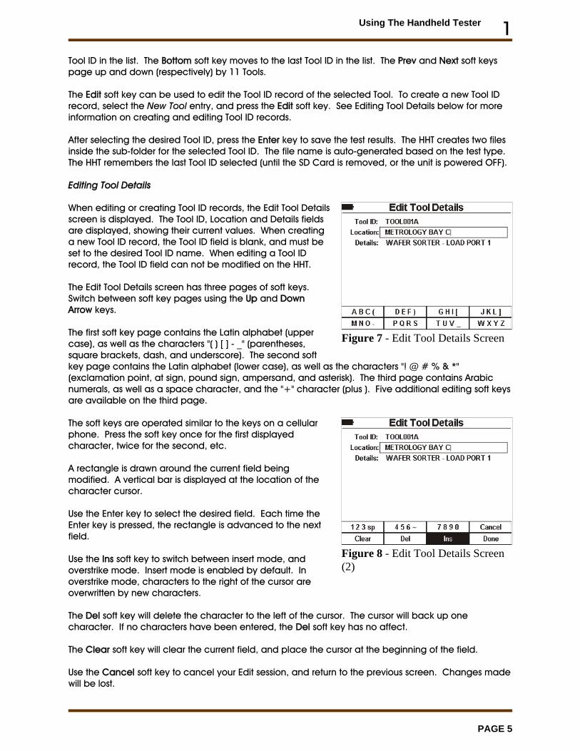
Tool ID in the list. The Bottom soft key moves to the last Tool ID in the list. The Prev and Next soft keyspage up and down (respectively) by 11 Tools.
The Edit soft key can be used to edit the Tool ID record of the selected Tool. To create a new Tool IDrecord, select the New Tool entry, and press the Edit soft key. See Editing Tool Details below for moreinformation on creating and editing Tool ID records.
After selecting the desired Tool ID, press the Enter key to save the test results. The HHT creates two filesinside the sub-folder for the selected Tool ID. The file name is auto-generated based on the test type. The HHT remembers the last Tool ID selected (until the SD Card is removed, or the unit is powered OFF).
Editing Tool Details
When editing or creating Tool ID records, the Edit Tool Detailsscreen is displayed. The Tool ID, Location and Details fieldsare displayed, showing their current values. When creatinga new Tool ID record, the Tool ID field is blank, and must beset to the desired Tool ID name. When editing a Tool IDrecord, the Tool ID field can not be modified on the HHT.
The Edit Tool Details screen has three pages of soft keys. Switch between soft key pages using the Up and DownArrow keys.
The first soft key page contains the Latin alphabet (uppercase), as well as the characters "( ) [ ] - _" (parentheses,square brackets, dash, and underscore). The second softkey page contains the Latin alphabet (lower case), as well as the characters "! @ # % & *"(exclamation point, at sign, pound sign, ampersand, and asterisk). The third page contains Arabicnumerals, as well as a space character, and the "+" character (plus ). Five additional editing soft keysare available on the third page.
The soft keys are operated similar to the keys on a cellularphone. Press the soft key once for the first displayedcharacter, twice for the second, etc.
A rectangle is drawn around the current field beingmodified. A vertical bar is displayed at the location of thecharacter cursor.
Use the Enter key to select the desired field. Each time theEnter key is pressed, the rectangle is advanced to the nextfield.
Use the Ins soft key to switch between insert mode, andoverstrike mode. Insert mode is enabled by default. Inoverstrike mode, characters to the right of the cursor areoverwritten by new characters.
The Del soft key will delete the character to the left of the cursor. The cursor will back up onecharacter. If no characters have been entered, the Del soft key has no affect.
The Clear soft key will clear the current field, and place the cursor at the beginning of the field.
Use the Cancel soft key to cancel your Edit session, and return to the previous screen. Changes madewill be lost.
Using The Handheld Tester 1
PAGE 6
Figure 9 - Main Test Menu
Figure 10 - Standard Cycle TestMenu
Use the Done soft key to end the editing session, and save all changes.
Press the Right Arrow key to move to the next character in the current field. If the cursor is at the end ofthe field, the Right Arrow key will insert a space character.
Press the Left Arrow key to move the cursor to the left.
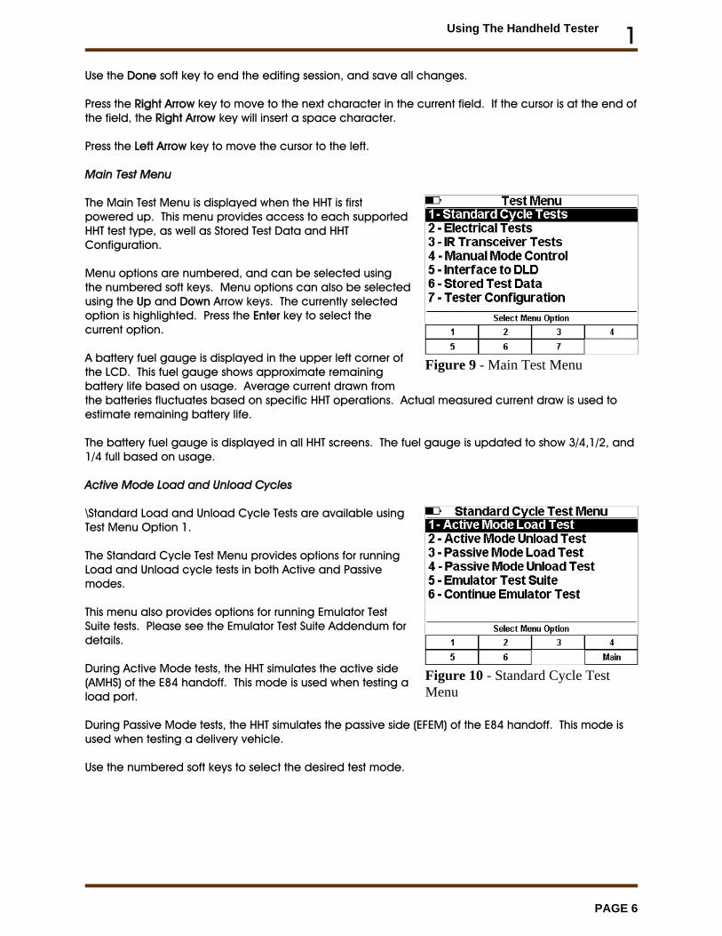
Main Test Menu
The Main Test Menu is displayed when the HHT is firstpowered up. This menu provides access to each supportedHHT test type, as well as Stored Test Data and HHTConfiguration.
Menu options are numbered, and can be selected usingthe numbered soft keys. Menu options can also be selectedusing the Up and Down Arrow keys. The currently selectedoption is highlighted. Press the Enter key to select thecurrent option.
A battery fuel gauge is displayed in the upper left corner ofthe LCD. This fuel gauge shows approximate remainingbattery life based on usage. Average current drawn fromthe batteries fluctuates based on specific HHT operations. Actual measured current draw is used toestimate remaining battery life.
The battery fuel gauge is displayed in all HHT screens. The fuel gauge is updated to show 3/4,1/2, and1/4 full based on usage.
Active Mode Load and Unload Cycles
\Standard Load and Unload Cycle Tests are available usingTest Menu Option 1.
The Standard Cycle Test Menu provides options for runningLoad and Unload cycle tests in both Active and Passivemodes.
This menu also provides options for running Emulator TestSuite tests. Please see the Emulator Test Suite Addendum fordetails.
During Active Mode tests, the HHT simulates the active side(AMHS) of the E84 handoff. This mode is used when testing aload port.
During Passive Mode tests, the HHT simulates the passive side (EFEM) of the E84 handoff. This mode isused when testing a delivery vehicle.
Use the numbered soft keys to select the desired test mode.
Using The Handheld Tester 1
PAGE 7
Figure 11 - Active Mode LoadCycle - Internal IR
Figure 12 - External IR Connection
Figure 13 - Direct Connection
Figure 14 - Load Cycle GraphWindow
Figure 15 - Load Cycle Complete
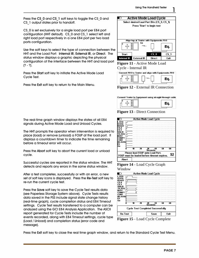
Press the CS_0 and CS_1 soft keys to toggle the CS_0 andCS_1 output states prior to handoff.
CS_0 is set exclusively for a single load port per E84 portconfiguration (HHT default). CS_0 and CS_1 select left andright load port respectively in a one E84 port per two loadports configuration.
Use the soft keys to select the type of connection between theHHT and the Load Port: Internal IR, External IR, or Direct. Thestatus window displays a graphic depicting the physicalconfiguration of the interface between the HHT and load port(? - ?).
Press the Start soft key to initiate the Active Mode LoadCycle Test.
Press the Exit soft key to return to the Main Menu.
The real-time graph window displays the states of all E84signals during Active Mode Load and Unload Cycles.
The HHT prompts the operator when intervention is required toplace (load) or remove (unload) a FOUP at the load port. Itdisplays a countdown timer to indicate the time remainingbefore a timeout error will occur.
Press the Abort soft key to abort the current load or unloadcycle.
Successful cycles are reported in the status window. The HHTdetects and reports any errors in the same status window.
After a test completes, successfully or with an error, a newset of soft key icons is displayed. Press the Re-Test soft key tore-run the current cycle test.
Press the Save soft key to save the Cycle Test results data(see Paperless Storage System above). Cycle Tests resultsdata saved in the PSS include signal state change history(real-time graph), cycle completion status and E84 Timeoutsettings. Cycle Test results transferred to a computer can beanalyzed using the GCI E84 Analysis Application. The ASCIIreport generated for Cycle Tests include the number ofevents recorded, along with E84 Timeout settings, cycle type(Load / Unload) and completion status (error code andmessage).
Press the Exit soft key to close the real time graph window, and return to the Standard Cycle Test Menu.
Using The Handheld Tester 1
PAGE 8
Figure 16 - Power Supply VoltageTest
Figure 17 - Active Signal LevelsScreen - Voltage
Figure 18 - Active Signal Levels -Current
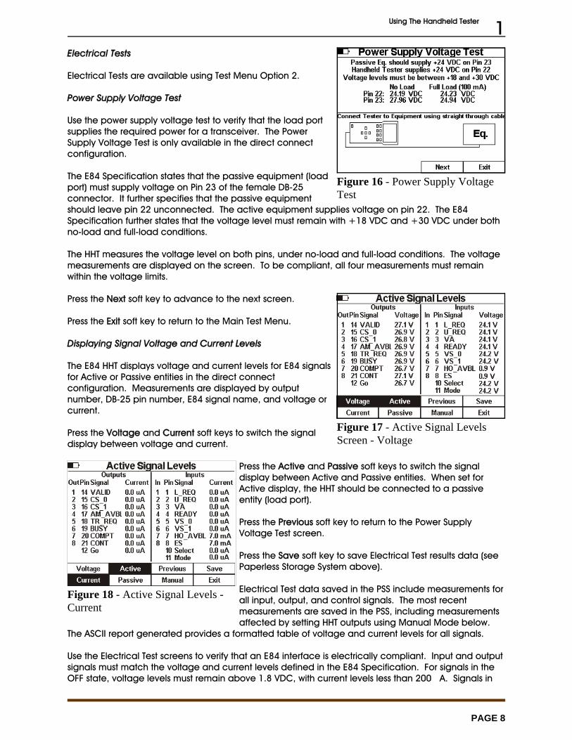
Electrical Tests
Electrical Tests are available using Test Menu Option 2.
Power Supply Voltage Test
Use the power supply voltage test to verify that the load portsupplies the required power for a transceiver. The PowerSupply Voltage Test is only available in the direct connectconfiguration.
The E84 Specification states that the passive equipment (loadport) must supply voltage on Pin 23 of the female DB-25connector. It further specifies that the passive equipmentshould leave pin 22 unconnected. The active equipment supplies voltage on pin 22. The E84Specification further states that the voltage level must remain with +18 VDC and +30 VDC under bothno-load and full-load conditions.
The HHT measures the voltage level on both pins, under no-load and full-load conditions. The voltagemeasurements are displayed on the screen. To be compliant, all four measurements must remainwithin the voltage limits.
Press the Next soft key to advance to the next screen.
Press the Exit soft key to return to the Main Test Menu.
Displaying Signal Voltage and Current Levels
The E84 HHT displays voltage and current levels for E84 signalsfor Active or Passive entities in the direct connectconfiguration. Measurements are displayed by outputnumber, DB-25 pin number, E84 signal name, and voltage orcurrent.
Press the Voltage and Current soft keys to switch the signaldisplay between voltage and current.
Press the Active and Passive soft keys to switch the signaldisplay between Active and Passive entities. When set forActive display, the HHT should be connected to a passiveentity (load port).
Press the Previous soft key to return to the Power SupplyVoltage Test screen.
Press the Save soft key to save Electrical Test results data (seePaperless Storage System above).
Electrical Test data saved in the PSS include measurements forall input, output, and control signals. The most recentmeasurements are saved in the PSS, including measurementsaffected by setting HHT outputs using Manual Mode below.
The ASCII report generated provides a formatted table of voltage and current levels for all signals.
Use the Electrical Test screens to verify that an E84 interface is electrically compliant. Input and outputsignals must match the voltage and current levels defined in the E84 Specification. For signals in theOFF state, voltage levels must remain above 1.8 VDC, with current levels less than 200 �A. Signals in
Using The Handheld Tester 1
PAGE 9
Figure 19 - Electrical Test - ManualMode
Figure 20 - IR Transceiver Test
Figure 21 - IR Transceiver TestAlignment
the ON state must have voltage levels less than 1.8 VDC, with current levels greater than 200 �A(typically in the mA range).
Press the Exit soft key to close the Electrical Test screen, and return to the Main Test Menu.
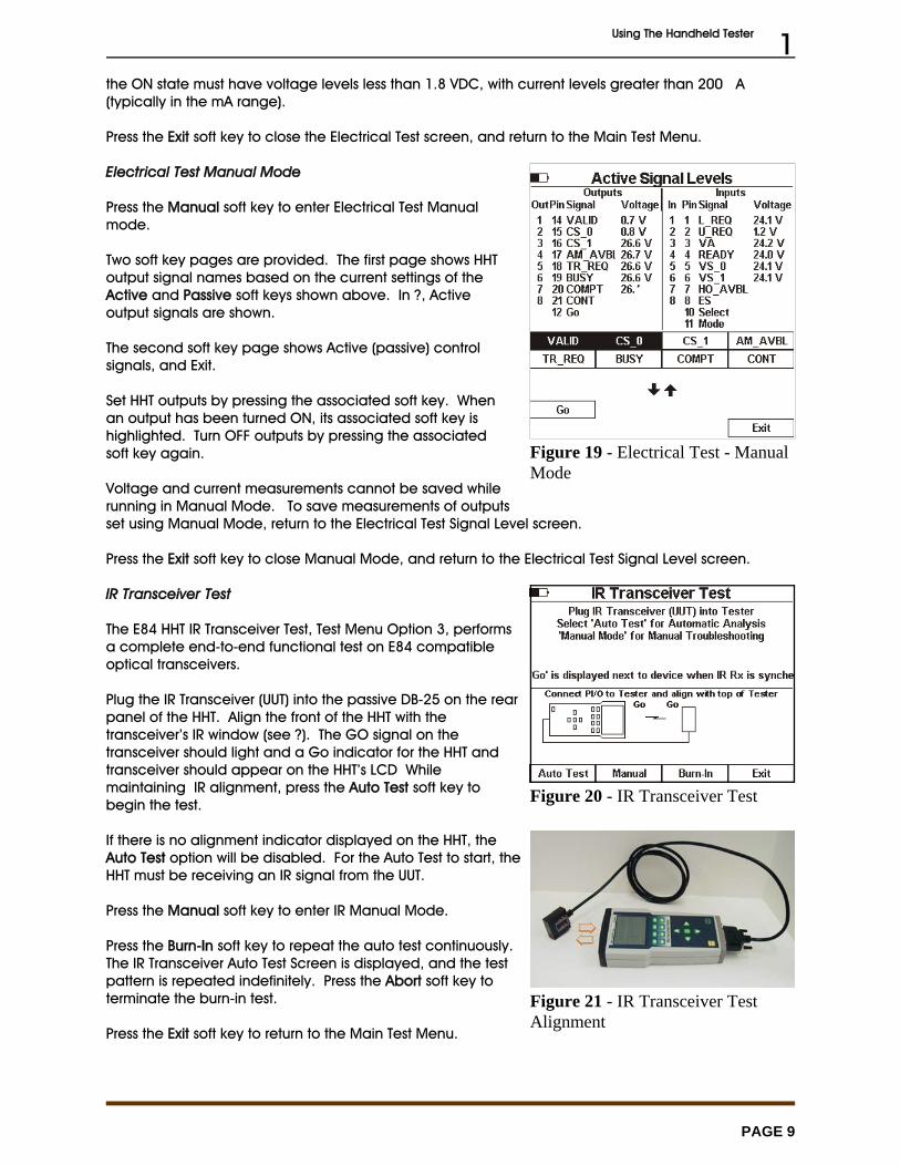
Electrical Test Manual Mode
Press the Manual soft key to enter Electrical Test Manualmode.
Two soft key pages are provided. The first page shows HHToutput signal names based on the current settings of theActive and Passive soft keys shown above. In ?, Activeoutput signals are shown.
The second soft key page shows Active (passive) controlsignals, and Exit.
Set HHT outputs by pressing the associated soft key. Whenan output has been turned ON, its associated soft key ishighlighted. Turn OFF outputs by pressing the associatedsoft key again.
Voltage and current measurements cannot be saved whilerunning in Manual Mode. To save measurements of outputsset using Manual Mode, return to the Electrical Test Signal Level screen.
Press the Exit soft key to close Manual Mode, and return to the Electrical Test Signal Level screen.
IR Transceiver Test
The E84 HHT IR Transceiver Test, Test Menu Option 3, performsa complete end-to-end functional test on E84 compatibleoptical transceivers.
Plug the IR Transceiver (UUT) into the passive DB-25 on the rearpanel of the HHT. Align the front of the HHT with thetransceiver’s IR window (see ?). The GO signal on thetransceiver should light and a Go indicator for the HHT andtransceiver should appear on the HHT’s LCD Whilemaintaining IR alignment, press the Auto Test soft key tobegin the test.
If there is no alignment indicator displayed on the HHT, theAuto Test option will be disabled. For the Auto Test to start, theHHT must be receiving an IR signal from the UUT.
Press the Manual soft key to enter IR Manual Mode.
Press the Burn-In soft key to repeat the auto test continuously. The IR Transceiver Auto Test Screen is displayed, and the testpattern is repeated indefinitely. Press the Abort soft key toterminate the burn-in test.
Press the Exit soft key to return to the Main Test Menu.
Using The Handheld Tester 1
PAGE 10
Figure 22 - IR Auto Test Active
Figure 23 - IR Auto Test with Errors
Figure 24 - IR Transceiver TestSummary Screen
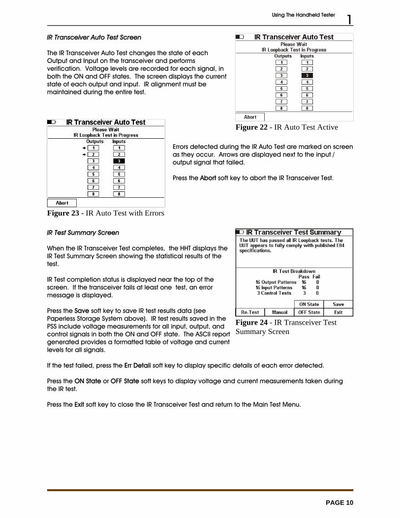
IR Transceiver Auto Test Screen
The IR Transceiver Auto Test changes the state of eachOutput and Input on the transceiver and performsverification. Voltage levels are recorded for each signal, inboth the ON and OFF states. The screen displays the currentstate of each output and input. IR alignment must bemaintained during the entire test.
Errors detected during the IR Auto Test are marked on screenas they occur. Arrows are displayed next to the input /output signal that failed.
Press the Abort soft key to abort the IR Transceiver Test.
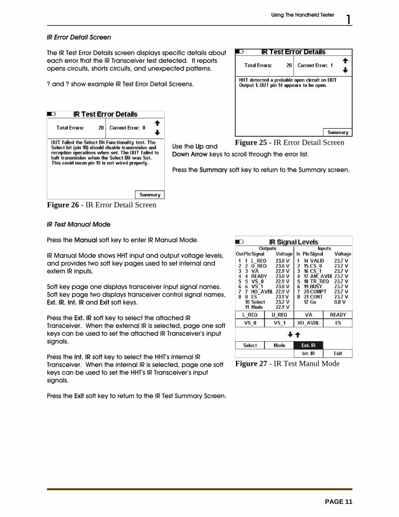
IR Test Summary Screen
When the IR Transceiver Test completes, the HHT displays theIR Test Summary Screen showing the statistical results of thetest.
IR Test completion status is displayed near the top of thescreen. If the transceiver fails at least one test, an errormessage is displayed.
Press the Save soft key to save IR test results data (seePaperless Storage System above). IR test results saved in thePSS include voltage measurements for all input, output, andcontrol signals in both the ON and OFF state. The ASCII reportgenerated provides a formatted table of voltage and currentlevels for all signals.
If the test failed, press the Err Detail soft key to display specific details of each error detected.
Press the ON State or OFF State soft keys to display voltage and current measurements taken duringthe IR test.
Press the Exit soft key to close the IR Transceiver Test and return to the Main Test Menu.
Using The Handheld Tester 1
PAGE 11
Figure 25 - IR Error Detail Screen
Figure 26 - IR Error Detail Screen
Figure 27 - IR Test Manul Mode
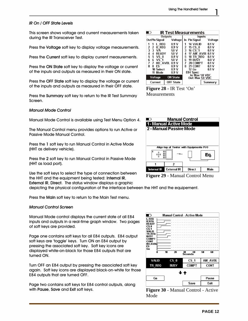
IR Error Detail Screen
The IR Test Error Details screen displays specific details abouteach error that the IR Transceiver test detected. It reportsopens circuits, shorts circuits, and unexpected patterns.
? and ? show example IR Test Error Detail Screens.
Use the Up andDown Arrow keys to scroll through the error list.
Press the Summary soft key to return to the Summary screen.
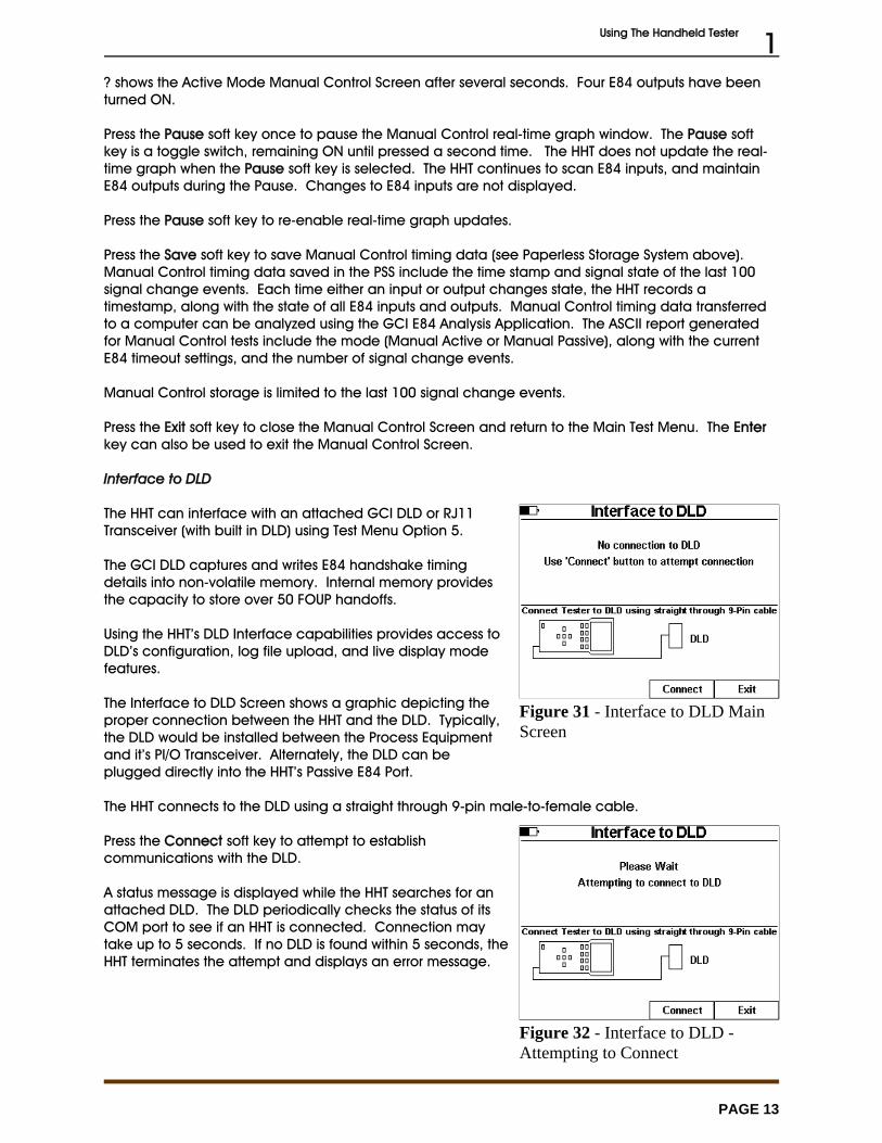
IR Test Manual Mode
Press the Manual soft key to enter IR Manual Mode.
IR Manual Mode shows HHT input and output voltage levels,and provides two soft key pages used to set internal andextern IR inputs.
Soft key page one displays transceiver input signal names. Soft key page two displays transceiver control signal names,Ext. IR, Int. IR and Exit soft keys.
Press the Ext. IR soft key to select the attached IRTransceiver. When the external IR is selected, page one softkeys can be used to set the attached IR Transceiver’s inputsignals.
Press the Int. IR soft key to select the HHT’s internal IRTransceiver. When the internal IR is selected, page one softkeys can be used to set the HHT’s IR Transceiver’s inputsignals.
Press the Exit soft key to return to the IR Test Summary Screen.
Using The Handheld Tester 1
PAGE 12
Figure 28 - IR Test ‘On’Measurements
Figure 29 - Manual Control Menu
Figure 30 - Manual Control - ActiveMode
IR On / OFF State Levels
This screen shows voltage and current measurements takenduring the IR Transceiver Test.
Press the Voltage soft key to display voltage measurements.
Press the Current soft key to display current measurements.
Press the ON State soft key to display the voltage or currentof the inputs and outputs as measured in their ON state.
Press the OFF State soft key to display the voltage or currentof the inputs and outputs as measured in their OFF state.
Press the Summary soft key to return to the IR Test SummaryScreen.
Manual Mode Control
Manual Mode Control is available using Test Menu Option 4.
The Manual Control menu provides options to run Active orPassive Mode Manual Control.
Press the 1 soft key to run Manual Control in Active Mode(HHT as delivery vehicle).
Press the 2 soft key to run Manual Control in Passive Mode(HHT as load port).
Use the soft keys to select the type of connection betweenthe HHT and the equipment being tested: Internal IR,External IR, Direct. The status window displays a graphicdepicting the physical configuration of the interface between the HHT and the equipement.
Press the Main soft key to return to the Main Test menu.
Manual Control Screen
Manual Mode control displays the current state of all E84inputs and outputs in a real-time graph window. Two pagesof soft keys are provided.
Page one contains soft keys for all E84 outputs. E84 outputsoft keys are ‘toggle’ keys. Turn ON an E84 output bypressing the associated soft key. Soft key icons aredisplayed white-on-black for those E84 outputs that areturned ON.
Turn OFF an E84 output by pressing the associated soft keyagain. Soft key icons are displayed black-on-white for thoseE84 outputs that are turned OFF.
Page two contains soft keys for E84 control outputs, alongwith Pause, Save and Exit soft keys.
Using The Handheld Tester 1
PAGE 13
Figure 31 - Interface to DLD MainScreen
Figure 32 - Interface to DLD -Attempting to Connect
? shows the Active Mode Manual Control Screen after several seconds. Four E84 outputs have beenturned ON.
Press the Pause soft key once to pause the Manual Control real-time graph window. The Pause softkey is a toggle switch, remaining ON until pressed a second time. The HHT does not update the real-time graph when the Pause soft key is selected. The HHT continues to scan E84 inputs, and maintainE84 outputs during the Pause. Changes to E84 inputs are not displayed.
Press the Pause soft key to re-enable real-time graph updates.
Press the Save soft key to save Manual Control timing data (see Paperless Storage System above). Manual Control timing data saved in the PSS include the time stamp and signal state of the last 100signal change events. Each time either an input or output changes state, the HHT records atimestamp, along with the state of all E84 inputs and outputs. Manual Control timing data transferredto a computer can be analyzed using the GCI E84 Analysis Application. The ASCII report generatedfor Manual Control tests include the mode (Manual Active or Manual Passive), along with the currentE84 timeout settings, and the number of signal change events.
Manual Control storage is limited to the last 100 signal change events.
Press the Exit soft key to close the Manual Control Screen and return to the Main Test Menu. The Enterkey can also be used to exit the Manual Control Screen.
Interface to DLD
The HHT can interface with an attached GCI DLD or RJ11Transceiver (with built in DLD) using Test Menu Option 5.
The GCI DLD captures and writes E84 handshake timingdetails into non-volatile memory. Internal memory providesthe capacity to store over 50 FOUP handoffs.
Using the HHT’s DLD Interface capabilities provides access toDLD’s configuration, log file upload, and live display modefeatures.
The Interface to DLD Screen shows a graphic depicting theproper connection between the HHT and the DLD. Typically,the DLD would be installed between the Process Equipmentand it’s PI/O Transceiver. Alternately, the DLD can beplugged directly into the HHT’s Passive E84 Port.
The HHT connects to the DLD using a straight through 9-pin male-to-female cable.
Press the Connect soft key to attempt to establishcommunications with the DLD.
A status message is displayed while the HHT searches for anattached DLD. The DLD periodically checks the status of itsCOM port to see if an HHT is connected. Connection maytake up to 5 seconds. If no DLD is found within 5 seconds, theHHT terminates the attempt and displays an error message.

Using The Handheld Tester 1
PAGE 14
Figure 33 - Interface to DLD -Contact Established
Figure 34 - DLD Live ModeDisplay
Figure 35 - DLD Log File UploadScreen
Once contact is established, the HHT adds additional softkey options to the Interface to DLD Screen.
Press the Live soft key to enter the DLD Live Mode.
Press the Log soft key to upload the DLD’s log file.
Press the Config soft key to modify DLD configurationsettings.
Press the Exit soft key to return to the Main Test Menu.
DLD Live Mode
During DLD LiveMode, the HHT continuously updates a real-time graphwindow with data received from the attached DLD.
Press the Pause soft key to pause real-time graph updates. The HHT continuously receives data from the DLD whilepaused. Received data is not added to the real-timegraph.
Press the Pause soft key again to re-enable real-time graphupdates.
Press the Exit soft key to terminate DLD Live Mode and returnto the Interface to DLD Screen. There is currently no Saveoption during DLD Live mode.
DLD Log File
The HHT stores the DLD Log file in the PSS. Before starting the upload process, the HHT needs to knowwhere to store the Log file. The Save Test Results screen is displayed when the Log soft key is pressed. Select a Tool ID to save the DLD Log file to (see Saving Test Results Files above for details on selectingthe Tool ID). DLD Logs transferred to a computer can be analyzed using the GCI E84 AnalysisApplication (Version 2.70 or newer).
After selecting the Tool ID, the DLD Log Upload Screen will be displayed.
During the DLD Log Upload, the HHT displays a Please Waitprompt, along with a status bar showing progress of theupload.
Press any HHT key to abort the DLD Log Upload.

Using The Handheld Tester 1
PAGE 15
Figure 36 - DLD Log UploadCompleted
Figure 37 - DLD ConfigurationScreen
When the upload is completed, a status message is displayedshowing the number of DLD records received.
Press the Exit soft key to return to the Interface to DLD Screen.
HOWTO: Download the DLD Log - Step by Step Instructions
1. If the DLD is not connected to a tool, plug the DLD'smale DB25 connector into the HHT’s Passive E84 Port. The HHT will supply power to the DLD through thisinterface. If the DLD is already connected to a tool orother E84 interface, its DB25 connector does not needto be plugged into the HHT.
2. Use the DLD Comm Cable, GCI P/N 9101-22-122 (or amale-to-female DB9 straight-through cable) toconnect the DLD to the HHT’s COM port.
3. Select Test Menu Option 5 (Interface to DLD) from the HHT’s main menu.4. Press the Connect soft key to connect to the DLD.
If the HHT is unable to connect to the DLD, make sure that the DLD is firmly plugged into its power source. If it still can notconnect, and the HHT is not the DLD's power supplier, try disconnecting the DLD from the E84 interface to which it isconnected, and connect it to the HHT instead.
5. After a connection has been established, press the Log soft key.6. Select the proper Tool ID, and press the Enter key to continue.7. Monitor the download status displayed by the HHT.8. When the download completes, press the Exit soft key to close the DLD Log Upload Screen and
return to the Interface to DLD Screen.
DLD Configuration Screen
The DLD Configuration Screen provides a method of viewingand modifying current DLD settings.
Current DLD settings are displayed near the top of thescreen. Settings displayed include the DLD’s internal Dateand Time, it’s firmware Version Number and unique DLD ID.
If the DLD firmware supports statistics gathering, a series ofcounters are also displayed.
Two configurable options are supported by the DLD; ErrorTrapping and Idle Noise. Error Trapping limits the DLD torecord only failed E84 transactions. Idle Noise limits thespecial Error Trapping mode to record only those errors thatoccur during an E84 transaction.
The current state of the two configurable options are shown below the statistics counters. When theoption is enabled, an arrow is displayed to the left of the option text. In ?, both Error Trapping and IdleNoise options are enabled.
Using The Handheld Tester 1
PAGE 16
Figure 38 - Update DLDConfiguration
Figure 39 - Stored Test Data Menu
Figure 40 - Delete ToolWarning
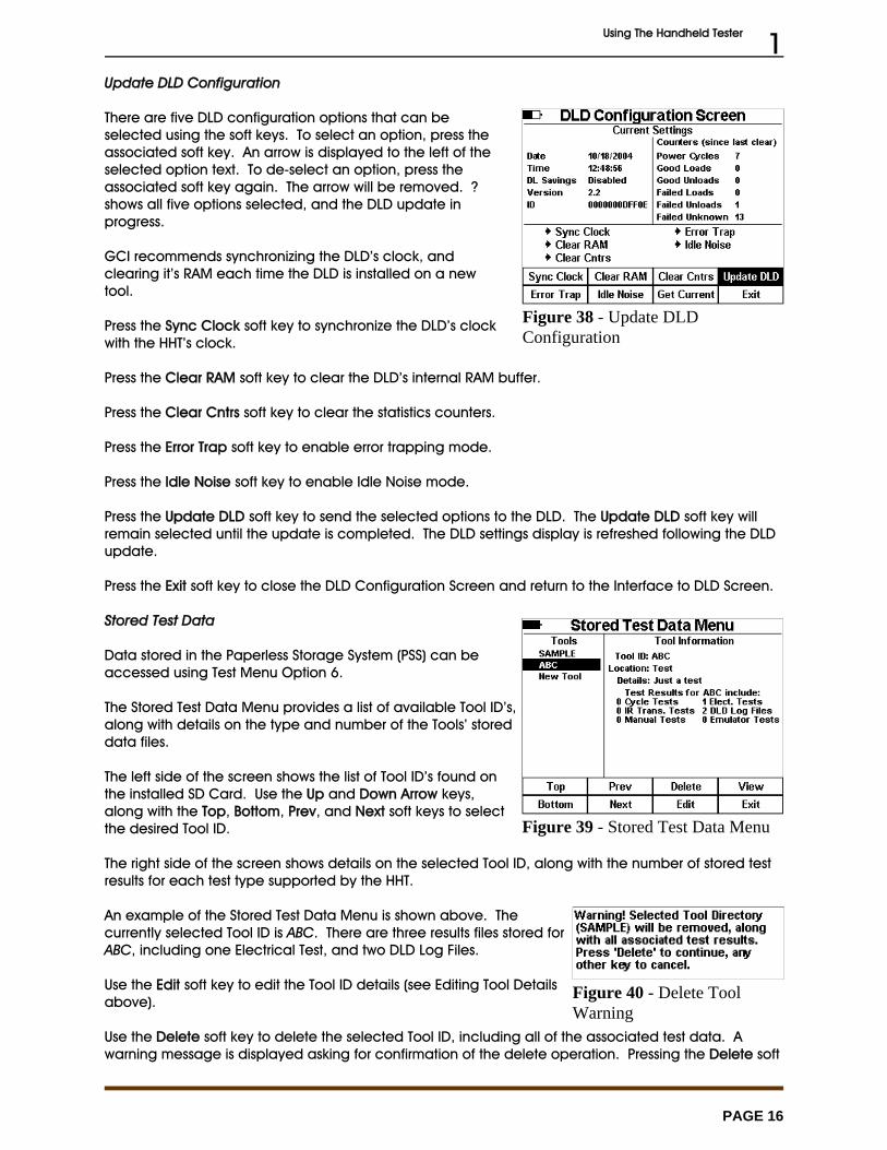
Update DLD Configuration
There are five DLD configuration options that can beselected using the soft keys. To select an option, press theassociated soft key. An arrow is displayed to the left of theselected option text. To de-select an option, press theassociated soft key again. The arrow will be removed. ?shows all five options selected, and the DLD update inprogress.
GCI recommends synchronizing the DLD’s clock, andclearing it’s RAM each time the DLD is installed on a newtool.
Press the Sync Clock soft key to synchronize the DLD’s clockwith the HHT’s clock.
Press the Clear RAM soft key to clear the DLD’s internal RAM buffer.
Press the Clear Cntrs soft key to clear the statistics counters.
Press the Error Trap soft key to enable error trapping mode.
Press the Idle Noise soft key to enable Idle Noise mode.
Press the Update DLD soft key to send the selected options to the DLD. The Update DLD soft key willremain selected until the update is completed. The DLD settings display is refreshed following the DLDupdate.
Press the Exit soft key to close the DLD Configuration Screen and return to the Interface to DLD Screen.
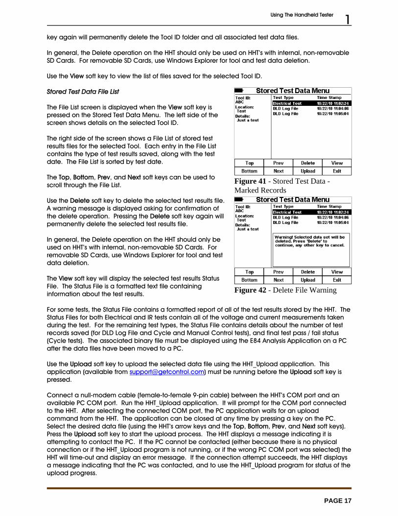
Stored Test Data
Data stored in the Paperless Storage System (PSS) can beaccessed using Test Menu Option 6.
The Stored Test Data Menu provides a list of available Tool ID’s,along with details on the type and number of the Tools’ storeddata files.
The left side of the screen shows the list of Tool ID’s found onthe installed SD Card. Use the Up and Down Arrow keys,along with the Top, Bottom, Prev, and Next soft keys to selectthe desired Tool ID.
The right side of the screen shows details on the selected Tool ID, along with the number of stored testresults for each test type supported by the HHT.
An example of the Stored Test Data Menu is shown above. Thecurrently selected Tool ID is ABC. There are three results files stored forABC, including one Electrical Test, and two DLD Log Files.
Use the Edit soft key to edit the Tool ID details (see Editing Tool Detailsabove).
Use the Delete soft key to delete the selected Tool ID, including all of the associated test data. Awarning message is displayed asking for confirmation of the delete operation. Pressing the Delete soft
Using The Handheld Tester 1
PAGE 17
Figure 41 - Stored Test Data -Marked Records
Figure 42 - Delete File Warning
key again will permanently delete the Tool ID folder and all associated test data files.
In general, the Delete operation on the HHT should only be used on HHT’s with internal, non-removableSD Cards. For removable SD Cards, use Windows Explorer for tool and test data deletion.
Use the View soft key to view the list of files saved for the selected Tool ID.
Stored Test Data File List
The File List screen is displayed when the View soft key ispressed on the Stored Test Data Menu. The left side of thescreen shows details on the selected Tool ID.
The right side of the screen shows a File List of stored testresults files for the selected Tool. Each entry in the File Listcontains the type of test results saved, along with the testdate. The File List is sorted by test date.
The Top, Bottom, Prev, and Next soft keys can be used toscroll through the File List.
Use the Delete soft key to delete the selected test results file. A warning message is displayed asking for confirmation ofthe delete operation. Pressing the Delete soft key again willpermanently delete the selected test results file.
In general, the Delete operation on the HHT should only beused on HHT’s with internal, non-removable SD Cards. Forremovable SD Cards, use Windows Explorer for tool and testdata deletion.
The View soft key will display the selected test results StatusFile. The Status File is a formatted text file containinginformation about the test results.
For some tests, the Status File contains a formatted report of all of the test results stored by the HHT. TheStatus Files for both Electrical and IR tests contain all of the voltage and current measurements takenduring the test. For the remaining test types, the Status File contains details about the number of testrecords saved (for DLD Log File and Cycle and Manual Control tests), and final test pass / fail status(Cycle tests). The associated binary file must be displayed using the E84 Analysis Application on a PCafter the data files have been moved to a PC.
Use the Upload soft key to upload the selected data file using the HHT_Upload application. Thisapplication (available from [email protected]) must be running before the Upload soft key ispressed.
Connect a null-modem cable (female-to-female 9-pin cable) between the HHT’s COM port and anavailable PC COM port. Run the HHT_Upload application. It will prompt for the COM port connectedto the HHT. After selecting the connected COM port, the PC application waits for an uploadcommand from the HHT. The application can be closed at any time by pressing a key on the PC.Select the desired data file (using the HHT’s arrow keys and the Top, Bottom, Prev, and Next soft keys). Press the Upload soft key to start the upload process. The HHT displays a message indicating it isattempting to contact the PC. If the PC cannot be contacted (either because there is no physicalconnection or if the HHT_Upload program is not running, or if the wrong PC COM port was selected) theHHT will time-out and display an error message. If the connection attempt succeeds, the HHT displaysa message indicating that the PC was contacted, and to use the HHT_Upload program for status of theupload progress.
Using The Handheld Tester 1
PAGE 18
Figure 43 - Upload CompleteMessage
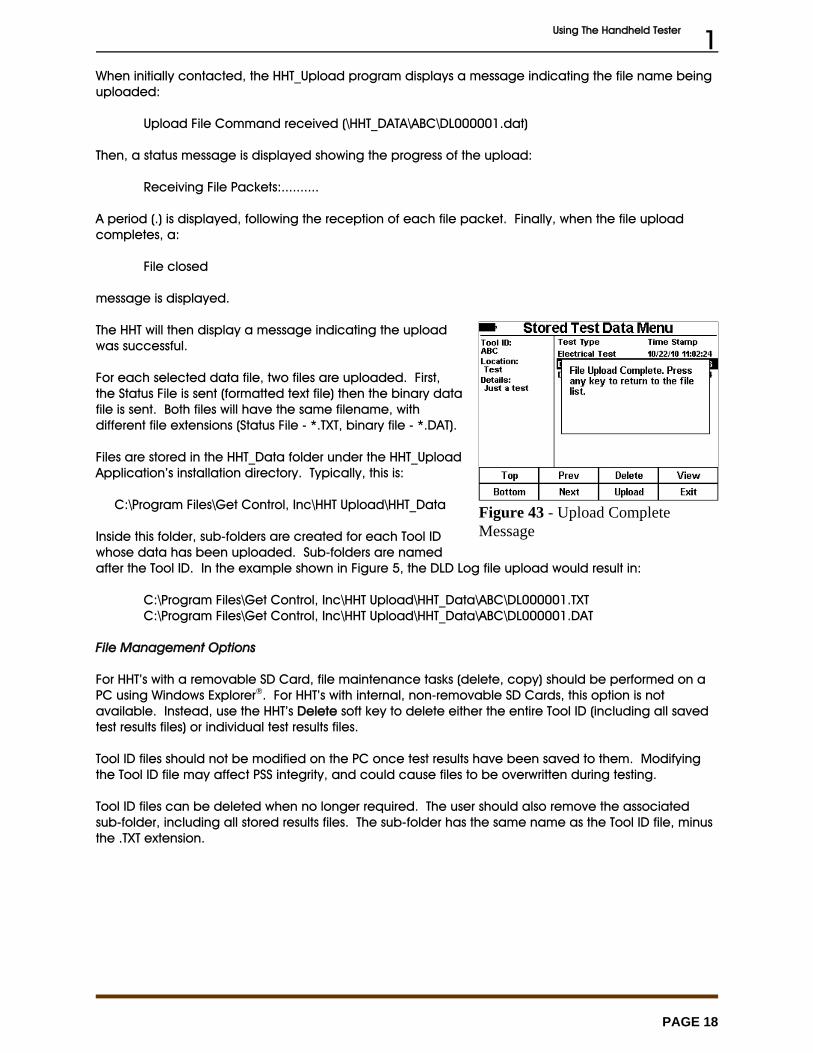
When initially contacted, the HHT_Upload program displays a message indicating the file name beinguploaded:
Upload File Command received (\HHT_DATA\ABC\DL000001.dat)
Then, a status message is displayed showing the progress of the upload:
Receiving File Packets:..........
A period (.) is displayed, following the reception of each file packet. Finally, when the file uploadcompletes, a:
File closed
message is displayed.
The HHT will then display a message indicating the uploadwas successful.
For each selected data file, two files are uploaded. First,the Status File is sent (formatted text file) then the binary datafile is sent. Both files will have the same filename, withdifferent file extensions (Status File - *.TXT, binary file - *.DAT).
Files are stored in the HHT_Data folder under the HHT_UploadApplication’s installation directory. Typically, this is:
C:\Program Files\Get Control, Inc\HHT Upload\HHT_Data
Inside this folder, sub-folders are created for each Tool IDwhose data has been uploaded. Sub-folders are namedafter the Tool ID. In the example shown in Figure 5, the DLD Log file upload would result in:
C:\Program Files\Get Control, Inc\HHT Upload\HHT_Data\ABC\DL000001.TXTC:\Program Files\Get Control, Inc\HHT Upload\HHT_Data\ABC\DL000001.DAT
File Management Options
For HHT’s with a removable SD Card, file maintenance tasks (delete, copy) should be performed on aPC using Windows Explorer®. For HHT’s with internal, non-removable SD Cards, this option is notavailable. Instead, use the HHT’s Delete soft key to delete either the entire Tool ID (including all savedtest results files) or individual test results files.
Tool ID files should not be modified on the PC once test results have been saved to them. Modifyingthe Tool ID file may affect PSS integrity, and could cause files to be overwritten during testing.
Tool ID files can be deleted when no longer required. The user should also remove the associatedsub-folder, including all stored results files. The sub-folder has the same name as the Tool ID file, minusthe .TXT extension.

Using The Handheld Tester 1
PAGE 19
Figure 44 - Tester Configuration -Time & Date
Figure 45 - Tester Configuration -E84 Timeouts
Configuring The Tester
Use the Tester Configuration Menu, Test Menu Option 7, toset the time and date, E84 timeouts, sleep and powertimeouts, default E84 communications method, and LCDcontrast. The firmware version and release date, along withthe battery voltage are also displayed in the TesterConfiguration Menu.
When adjusting any of the HHT configuration parameters,pressing and holding the Up / Down keys will cause theparameter to be continuously modified until the key isreleased.
Setting Time & Date
Press the Time/Date soft key to set the time and date. TheTime & Date section title is underlined to show that it is selected.
A rectangle is drawn around the hour to indicate it can be modified. Use the Up and Down arrow keysto increment and decrement the hour respectively. Use the Left and Right arrow keys to navigate therectangle to the minute, second, month, day, and year. After modifying the time and date, press theUpdate soft key to write the new date and time to the internal real-time clock.Setting E84 Timeout Values
Press the Timeouts soft key to modify the E84 timeouts. TheE84 Timeouts section title is underlined to show that it isselected. A rectangle is drawn around TA1. Use the Up and Downarrow keys to increment and decrement TA1 respectively. Use the Left and Right arrow keys to navigate the rectangleto TA2, TA3, TP1, TP2, TP3, TP4, TP5, and TP6.
E84 Timeout settings are used by the HHT during StandardCycle Tests and Emulator Test Suite tests. The current settingsare stored with Cycle Test, Manual Control, and Test Suitetest results when using the HHT’s Paperless Storage System(PSS).
Using The Handheld Tester 1
PAGE 20
Figure 46 - Tester Configuration -Power Settings
Figure 47 - Tester Configuration -Comm Method
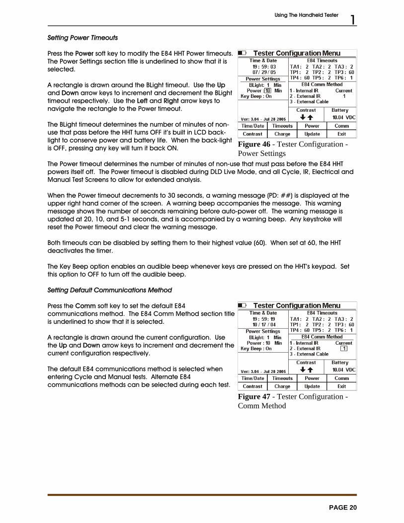
Setting Power Timeouts
Press the Power soft key to modify the E84 HHT Power timeouts. The Power Settings section title is underlined to show that it isselected.
A rectangle is drawn around the BLight timeout. Use the Upand Down arrow keys to increment and decrement the BLighttimeout respectively. Use the Left and Right arrow keys tonavigate the rectangle to the Power timeout.
The BLight timeout determines the number of minutes of non-use that pass before the HHT turns OFF it’s built in LCD back-light to conserve power and battery life. When the back-lightis OFF, pressing any key will turn it back ON.
The Power timeout determines the number of minutes of non-use that must pass before the E84 HHTpowers itself off. The Power timeout is disabled during DLD Live Mode, and all Cycle, IR, Electrical andManual Test Screens to allow for extended analysis.
When the Power timeout decrements to 30 seconds, a warning message (PD: ##) is displayed at theupper right hand corner of the screen. A warning beep accompanies the message. This warningmessage shows the number of seconds remaining before auto-power off. The warning message isupdated at 20, 10, and 5-1 seconds, and is accompanied by a warning beep. Any keystroke willreset the Power timeout and clear the warning message.
Both timeouts can be disabled by setting them to their highest value (60). When set at 60, the HHTdeactivates the timer.
The Key Beep option enables an audible beep whenever keys are pressed on the HHT’s keypad. Setthis option to OFF to turn off the audible beep.
Setting Default Communications Method
Press the Comm soft key to set the default E84communications method. The E84 Comm Method section titleis underlined to show that it is selected.
A rectangle is drawn around the current configuration. Usethe Up and Down arrow keys to increment and decrement thecurrent configuration respectively.
The default E84 communications method is selected whenentering Cycle and Manual tests. Alternate E84communications methods can be selected during each test.
Using The Handheld Tester 1
PAGE 21
Figure 48 - Tester Configuration -Contrast
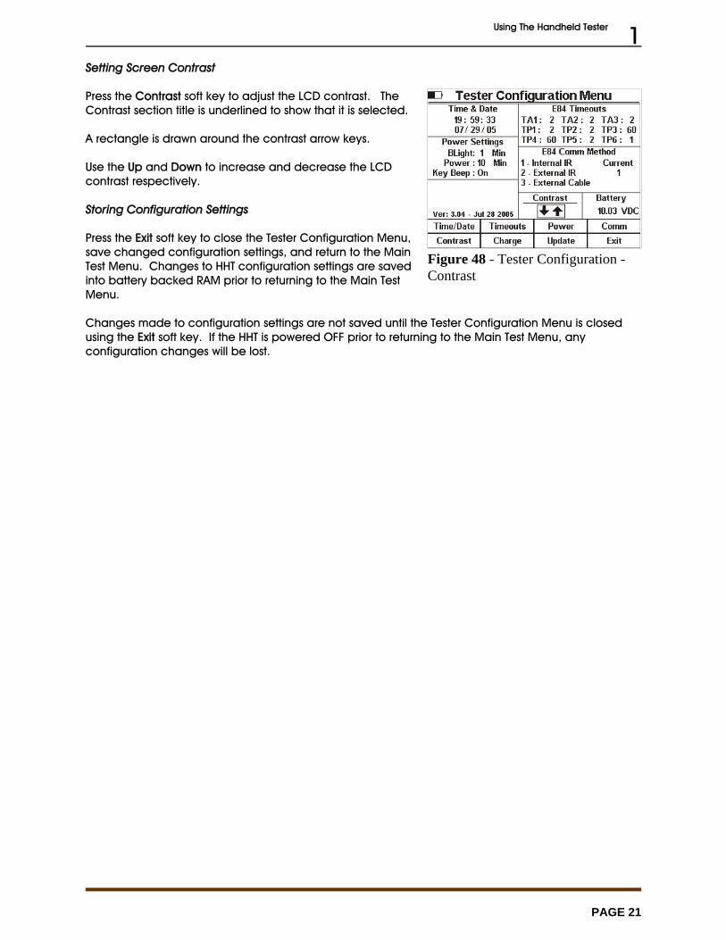
Setting Screen Contrast
Press the Contrast soft key to adjust the LCD contrast. TheContrast section title is underlined to show that it is selected.
A rectangle is drawn around the contrast arrow keys.
Use the Up and Down to increase and decrease the LCDcontrast respectively.
Storing Configuration Settings
Press the Exit soft key to close the Tester Configuration Menu,save changed configuration settings, and return to the MainTest Menu. Changes to HHT configuration settings are savedinto battery backed RAM prior to returning to the Main TestMenu.
Changes made to configuration settings are not saved until the Tester Configuration Menu is closedusing the Exit soft key. If the HHT is powered OFF prior to returning to the Main Test Menu, anyconfiguration changes will be lost.

Using The Handheld Tester 1
PAGE 22
Figure 49 - Charging the HHT
Figure 50 - Charge Battery Screen
Charging the Rechargeable Battery Pack
At delivery, the batteries may be empty and shouldbe charged. Charging time is 4 hours. When fullycharged, the batteries provide 8 to 16 hours of usedepending on the E84 HHT functions performed.
The useable battery range is 8 to 12 Volts. Batteryvoltage is displayed on the configuration menu forreference. When the battery voltage drops below 9Volts, a Lo Bat (low-battery) indicator appears in theupper left corner of the LCD to indicate charging isrequired. If battery voltage drops below 8 Volts, theHHT automatically powers OFF.
If the HHT’s battery level drops too low, the HHT willnot power up properly. In this case, connect thewall transformer to the HHT, and allow the batteriesto trickle charge for a short time (10 minutes or so). The HHT batteries should receive enough boost fromthe attached wall transformer to allow proper powerup. Immediately enter the charge screen andbegin a charge cycle.
The battery fuel gauge is reset to Full following a successful charge cycle.
Enter the Configuration screen using Option 7 from the TestMenu. Press the Charge soft key to display the ChargeBattery Screen. This screen displays battery statusinformation. This information is valid only when the 15 VDCwall supply is not connected. If connected, the 15 VDCsupply will influence battery levels, and cause the HHT toimproperly report that no charge is required.
Plug the 15 VDC wall supply to a 120 VAC source. Connectthe wall supply into the front panel connector on the E84HHT.
From the Charge Battery Screen, press the Charge soft keyto begin charging. The Charging Batteries screen displaysthe current battery voltage, battery temperature, charge current, charge time, and maximum time tocharge completion. After the batteries are fully charged, the E84 HHT terminates the charge cycle,and displays final charge statistics.
The Power timeout is disabled during the charge cycle. When the charge cycle completes, the Powertimeout is reactivated. This allows for over-night re-charging. When the charge cycle completes, thecharge statistics will be displayed. Following the Power timeout period, the HHT will auto-power down. Ensure that the Power timeout is not disabled (using a value of 60) when charging over-night.HHT Firmware Field Update
The HHT firmware is continuously being updated to add new features. When an update is released, itis placed on the GCI web-site at:
www.getcontrol.com/products/e84handheld_tester.html
To update the HHT firmware, download the update file from the GCI web-site. The update filenameincludes the version number of the update. When updating the HHT, the file must be renamed to
Using The Handheld Tester 1
PAGE 23
Figure 51 - Field Update Screen
Figure 52 - Field Update ErrorScreen
Figure 53 - Field Update DetailScreen
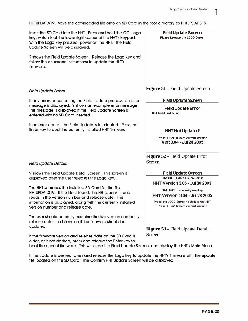
HHTUPDAT.S19. Save the downloaded file onto an SD Card in the root directory as HHTUPDAT.S19.
Insert the SD Card into the HHT. Press and hold the GCI Logokey, which is at the lower right corner of the HHT’s keypad. With the Logo key pressed, power on the HHT. The FieldUpdate Screen will be displayed.
? shows the Field Update Screen. Release the Logo key andfollow the on-screen instructions to update the HHT’sfirmware.
Field Update Errors
If any errors occur during the Field Update process, an errormessage is displayed. ? shows an example error message. This message is displayed if the Field Update Screen isentered with no SD Card inserted.
If an error occurs, the Field Update is terminated. Press theEnter key to boot the currently installed HHT firmware.
Field Update Details
? shows the Field Update Detail Screen. This screen isdisplayed after the user releases the Logo key.
The HHT searches the installed SD Card for the fileHHTUPDAT.S19. If the file is found, the HHT opens it, andreads in the version number and release date. Thisinformation is displayed, along with the currently installedversion number and release date.
The user should carefully examine the two version numbers /release dates to determine if the firmware should beupdated.
If the firmware version and release date on the SD Card isolder, or is not desired, press and release the Enter key toboot the current firmware. This will close the Field Update Screen, and display the HHT’s Main Menu.
If the update is desired, press and release the Logo key to update the HHT’s firmware with the updatefile located on the SD Card. The Confirm HHT Update Screen will be displayed.
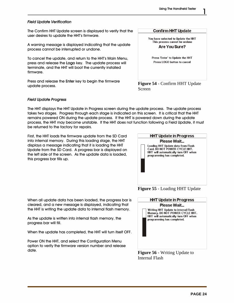
Using The Handheld Tester 1
PAGE 24
Figure 54 - Confirm HHT UpdateScreen
Figure 55 - Loading HHT Update
Figure 56 - Writing Update toInternal Flash
Field Update Verification
The Confirm HHT Update screen is displayed to verify that theuser desires to update the HHT’s firmware.
A warning message is displayed indicating that the updateprocess cannot be interrupted or undone.
To cancel the update, and return to the HHT’s Main Menu,press and release the Logo key. The update process willterminate, and the HHT will boot the currently installedfirmware.
Press and release the Enter key to begin the firmwareupdate process.
Field Update Progress
The HHT displays the HHT Update in Progress screen during the update process. The update processtakes two stages. Progress through each stage is indicated on this screen. It is critical that the HHTremains powered ON during the update process. If the HHT is powered down during the updateprocess, the HHT may become unstable. If the HHT does not function following a Field Update, it mustbe returned to the factory for repairs.
First, the HHT loads the firmware update from the SD Cardinto internal memory. During this loading stage, the HHTdisplays a message indicating that it is loading the HHTUpdate from the SD Card. A progress bar is displayed onthe left side of the screen. As the update data is loaded,this progress bar fills up.
When all update data has been loaded, the progress bar iscleared, and a new message is displayed, indicating thatthe HHT is writing the update data to internal flash memory.
As the update is written into internal flash memory, theprogress bar will fill.
When the update has completed, the HHT will turn itself OFF.
Power ON the HHT, and select the Configuration Menuoption to verify the firmware version number and releasedate.

Get Control, Inc.
E84 Handheld TesterGCI05001
Emulator Test Suite Addendum
March 1, 2006

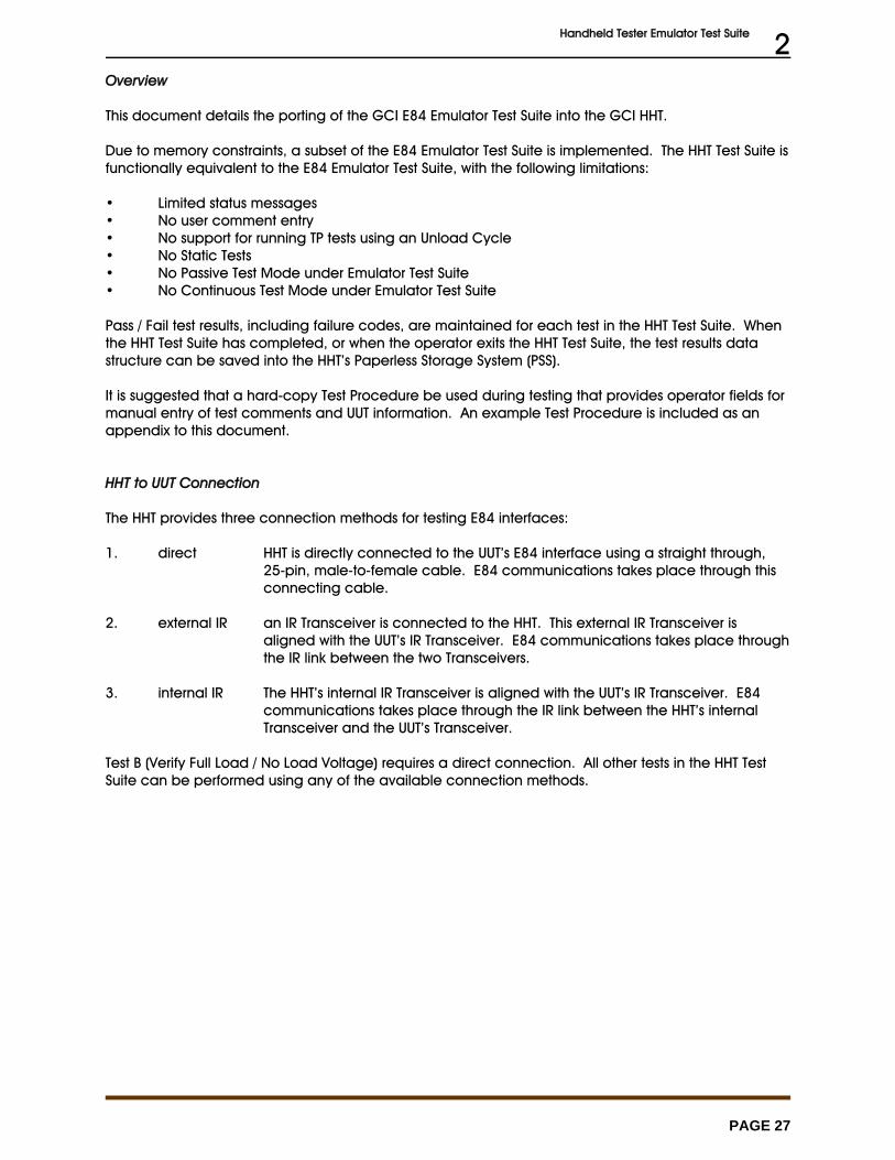
Handheld Tester Emulator Test Suite 2
PAGE 27
Overview
This document details the porting of the GCI E84 Emulator Test Suite into the GCI HHT.
Due to memory constraints, a subset of the E84 Emulator Test Suite is implemented. The HHT Test Suite isfunctionally equivalent to the E84 Emulator Test Suite, with the following limitations:
• Limited status messages• No user comment entry• No support for running TP tests using an Unload Cycle• No Static Tests• No Passive Test Mode under Emulator Test Suite• No Continuous Test Mode under Emulator Test Suite
Pass / Fail test results, including failure codes, are maintained for each test in the HHT Test Suite. Whenthe HHT Test Suite has completed, or when the operator exits the HHT Test Suite, the test results datastructure can be saved into the HHT’s Paperless Storage System (PSS).
It is suggested that a hard-copy Test Procedure be used during testing that provides operator fields formanual entry of test comments and UUT information. An example Test Procedure is included as anappendix to this document.
HHT to UUT Connection
The HHT provides three connection methods for testing E84 interfaces:
1. direct HHT is directly connected to the UUT’s E84 interface using a straight through,25-pin, male-to-female cable. E84 communications takes place through thisconnecting cable.
2. external IR an IR Transceiver is connected to the HHT. This external IR Transceiver isaligned with the UUT’s IR Transceiver. E84 communications takes place throughthe IR link between the two Transceivers.
3. internal IR The HHT’s internal IR Transceiver is aligned with the UUT’s IR Transceiver. E84communications takes place through the IR link between the HHT’s internalTransceiver and the UUT’s Transceiver.
Test B (Verify Full Load / No Load Voltage) requires a direct connection. All other tests in the HHT TestSuite can be performed using any of the available connection methods.
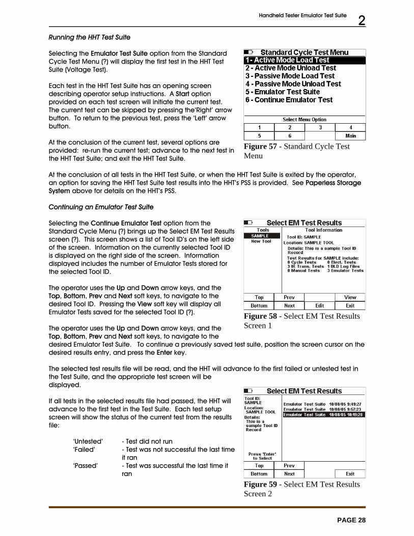
Handheld Tester Emulator Test Suite 2
PAGE 28
Figure 57 - Standard Cycle TestMenu
Figure 58 - Select EM Test ResultsScreen 1
Figure 59 - Select EM Test ResultsScreen 2
Running the HHT Test Suite
Selecting the Emulator Test Suite option from the StandardCycle Test Menu (?) will display the first test in the HHT TestSuite (Voltage Test).
Each test in the HHT Test Suite has an opening screendescribing operator setup instructions. A Start optionprovided on each test screen will initiate the current test. The current test can be skipped by pressing the‘Right’ arrowbutton. To return to the previous test, press the ‘Left’ arrowbutton.
At the conclusion of the current test, several options areprovided: re-run the current test; advance to the next test inthe HHT Test Suite; and exit the HHT Test Suite.
At the conclusion of all tests in the HHT Test Suite, or when the HHT Test Suite is exited by the operator,an option for saving the HHT Test Suite test results into the HHT’s PSS is provided. See Paperless StorageSystem above for details on the HHT’s PSS.
Continuing an Emulator Test Suite
Selecting the Continue Emulator Test option from theStandard Cycle Menu (?) brings up the Select EM Test Resultsscreen (?). This screen shows a list of Tool ID’s on the left sideof the screen. Information on the currently selected Tool IDis displayed on the right side of the screen. Informationdisplayed includes the number of Emulator Tests stored forthe selected Tool ID.
The operator uses the Up and Down arrow keys, and theTop, Bottom, Prev and Next soft keys, to navigate to thedesired Tool ID. Pressing the View soft key will display allEmulator Tests saved for the selected Tool ID (?).
The operator uses the Up and Down arrow keys, and theTop, Bottom, Prev and Next soft keys, to navigate to thedesired Emulator Test Suite. To continue a previously saved test suite, position the screen cursor on thedesired results entry, and press the Enter key.
The selected test results file will be read, and the HHT will advance to the first failed or untested test inthe Test Suite, and the appropriate test screen will bedisplayed.
If all tests in the selected results file had passed, the HHT willadvance to the first test in the Test Suite. Each test setupscreen will show the status of the current test from the resultsfile:
‘Untested’ - Test did not run‘Failed’ - Test was not successful the last time
it ran‘Passed’ - Test was successful the last time it
ran
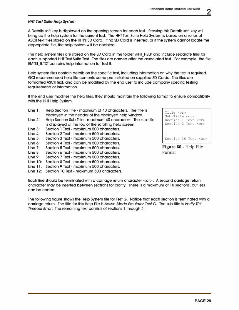
Handheld Tester Emulator Test Suite 2
PAGE 29
Title <cr>Sub-Title <cr>Section 1 Text <cr>Section 2 Text <cr>...Section 10 Text <cr>
Figure 60 - Help FileFormat
HHT Test Suite Help System
A Details soft key is displayed on the opening screen for each test. Pressing this Details soft key willbring up the help system for the current test. The HHT Test Suite Help System is based on a series ofASCII text files stored on the HHT’s SD Card. If no SD Card is inserted, or if the system cannot locate theappropriate file, the help system will be disabled.
The help system files are stored on the SD Card in the folder \HHT_HELP and include separate files foreach supported HHT Test Suite Test. The files are named after the associated test. For example, the file EMTST_B.TXT contains help information for Test B.
Help system files contain details on the specific test, including information on why the test is required. GCI recommended help file contents come pre-installed on supplied SD Cards. The files areformatted ASCII text, and can be modified by the end user to include company specific testingrequirements or information.
If the end user modifies the help files, they should maintain the following format to ensure compatibilitywith the HHT Help System.
Line 1: Help Section Title - maximum of 40 characters. The title isdisplayed in the header of the displayed help window.
Line 2: Help Section Sub-Title - maximum 40 characters. The sub-titleis displayed at the top of the scrolling help screen.
Line 3: Section 1 Text - maximum 500 characters. Line 4: Section 2 Text - maximum 500 characters.Line 5: Section 3 Text - maximum 500 characters.Line 6: Section 4 Text - maximum 500 characters.Line 7: Section 5 Text - maximum 500 characters.Line 8: Section 6 Text - maximum 500 characters.Line 9: Section 7 Text - maximum 500 characters.Line 10: Section 8 Text - maximum 500 characters.Line 11: Section 9 Text - maximum 500 characters.Line 12: Section 10 Text - maximum 500 characters.
Each line should be terminated with a carriage return character <cr>. A second carriage returncharacter may be inserted between sections for clarity. There is a maximum of 10 sections, but lesscan be coded.
The following figure shows the Help System file for Test G. Notice that each section is terminated with acarriage return. The title for this Help File is Active Mode Emulator Test G. The sub-title is Verify TP1Timeout Error. The remaining text consists of sections 1 through 4.
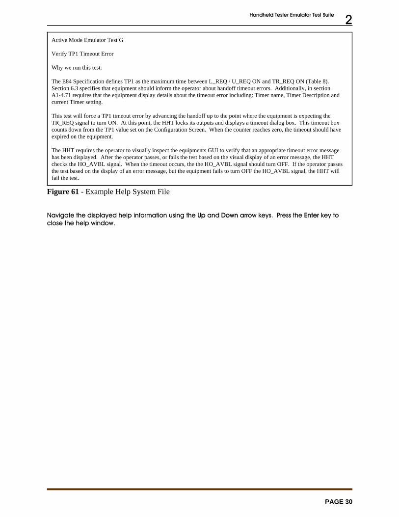
Handheld Tester Emulator Test Suite 2
PAGE 30
Active Mode Emulator Test G
Verify TP1 Timeout Error
Why we run this test:
The E84 Specification defines TP1 as the maximum time between L_REQ / U_REQ ON and TR_REQ ON (Table 8). Section 6.3 specifies that equipment should inform the operator about handoff timeout errors. Additionally, in sectionA1-4.71 requires that the equipment display details about the timeout error including: Timer name, Timer Description andcurrent Timer setting.
This test will force a TP1 timeout error by advancing the handoff up to the point where the equipment is expecting theTR_REQ signal to turn ON. At this point, the HHT locks its outputs and displays a timeout dialog box. This timeout boxcounts down from the TP1 value set on the Configuration Screen. When the counter reaches zero, the timeout should haveexpired on the equipment.
The HHT requires the operator to visually inspect the equipments GUI to verify that an appropriate timeout error messagehas been displayed. After the operator passes, or fails the test based on the visual display of an error message, the HHTchecks the HO_AVBL signal. When the timeout occurs, the the HO_AVBL signal should turn OFF. If the operator passesthe test based on the display of an error message, but the equipment fails to turn OFF the HO_AVBL signal, the HHT willfail the test.
Figure 61 - Example Help System File
Navigate the displayed help information using the Up and Down arrow keys. Press the Enter key toclose the help window.
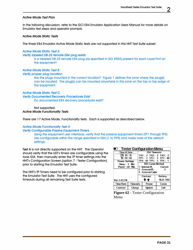
Handheld Tester Emulator Test Suite 2
PAGE 31
Figure 62 - Tester ConfigurationMenu
Active Mode Test Plan
In the following discussion, refer to the GCI E84 Emulator Application Users Manual for more details onEmulator test steps and operator prompts.
Active Mode Static Tests
The three E84 Emulator Active Mode Static tests are not supported in this HHT Test Suite subset.
Active Mode Static Test AVerify labeled DB-25 female E84 plug exists
Is a labeled DB-25 female E84 plug (as specified in ISO 4902) present for each Load Port onthe equipment?
Active Mode Static Test BVerify proper plug location
Are the plugs mounted in the correct location? Figure 1 defines the zone where the plug(s)can be located. The plug(s) can be mounted anywhere in this zone on the top or top edge ofthe equipment.
Active Mode Static Test CVerify Documented Recovery Procedures Exist
Do documented E84 recovery procedures exist?
Not supported. Active Mode Functionality Tests
There are 17 Active Mode, Functionality tests. Each is supported as described below.
Active Mode Functionality Test AVerify Configurable Passive Equipment Timers
Using the equipment user interface, verify that the passive equipment timers (TP1 through TP5)are configurable within the range specified in E84 (1 to 999) and make note of the defaultsettings:
Test A is not directly supported on the HHT. The Operatorshould verify that the UUT’s timers are configurable using thetools GUI, then manually enter the TP timer settings into theHHT’s Configuration Screen (option 7 - Tester Configuration)prior to starting the Emulator Test Suite.
The HHT’s TP Timers need to be configured prior to startingthe Emulator Test Suite. The HHT uses the configuredtimeouts during all remaining Test Suite tests.
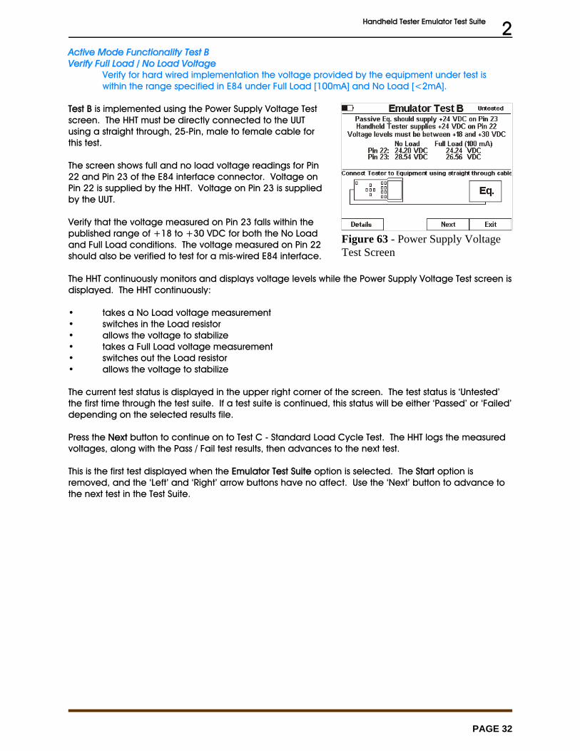
Handheld Tester Emulator Test Suite 2
PAGE 32
Figure 63 - Power Supply VoltageTest Screen
Active Mode Functionality Test BVerify Full Load / No Load Voltage
Verify for hard wired implementation the voltage provided by the equipment under test iswithin the range specified in E84 under Full Load [100mA] and No Load [<2mA].
Test B is implemented using the Power Supply Voltage Testscreen. The HHT must be directly connected to the UUTusing a straight through, 25-Pin, male to female cable forthis test.
The screen shows full and no load voltage readings for Pin22 and Pin 23 of the E84 interface connector. Voltage onPin 22 is supplied by the HHT. Voltage on Pin 23 is suppliedby the UUT.
Verify that the voltage measured on Pin 23 falls within thepublished range of +18 to +30 VDC for both the No Loadand Full Load conditions. The voltage measured on Pin 22should also be verified to test for a mis-wired E84 interface.
The HHT continuously monitors and displays voltage levels while the Power Supply Voltage Test screen isdisplayed. The HHT continuously:
• takes a No Load voltage measurement• switches in the Load resistor• allows the voltage to stabilize• takes a Full Load voltage measurement• switches out the Load resistor• allows the voltage to stabilize
The current test status is displayed in the upper right corner of the screen. The test status is ‘Untested’the first time through the test suite. If a test suite is continued, this status will be either ‘Passed’ or ‘Failed’depending on the selected results file.
Press the Next button to continue on to Test C - Standard Load Cycle Test. The HHT logs the measuredvoltages, along with the Pass / Fail test results, then advances to the next test.
This is the first test displayed when the Emulator Test Suite option is selected. The Start option isremoved, and the ‘Left’ and ‘Right’ arrow buttons have no affect. Use the ‘Next’ button to advance tothe next test in the Test Suite.

Handheld Tester Emulator Test Suite 2
PAGE 33
Figure 64 - Test C Setup Screen
Figure 65 - Test C In Progress
Figure 66 - Test C Completed
Active Mode Functionality Test CVerify Single handoff sequence for Loading.
Verify single handoff sequence for Loading. See Figure 2 for example signal timing diagram.
Test C is implemented using the Active Mode Load Cyclescreen. This screen runs a standard Load Cycle test usingCS_0 (default) or CS_1. The operator should select thedesired port selection signal. Typically, CS_0 should beused.
? shows the test setup screen for Test C. The connectionmethod defaults to Direct. The operator should select thedesired connection method. The test title is displayed in themiddle of the screen.
When the Start option is selected, the Active Mode LoadCycle screen is displayed.
? shows an example of a Failed test status. When ‘Failed’ is displayed at the upper right of the screen,the current test results indicate that this test had failed the last time it ran.
The operator is prompted to load a FOUP onto the UUT at theproper point in the E84 handoff. A TP3 timeout counter isdisplayed in the status window showing the operator howmuch time is available to load the FOUP.
Cycle status is displayed in the status window, includingsuccessful completion or error condition.
When the cycle has completed, either successfully or withan error, the operator has the option of re-running thecurrent test, advancing to the next test in the HHT Test Suite,or exiting the HHT Test Suite.
At the end of the Cycle Test, the results code is added to theHHT Test Suite results data structure.
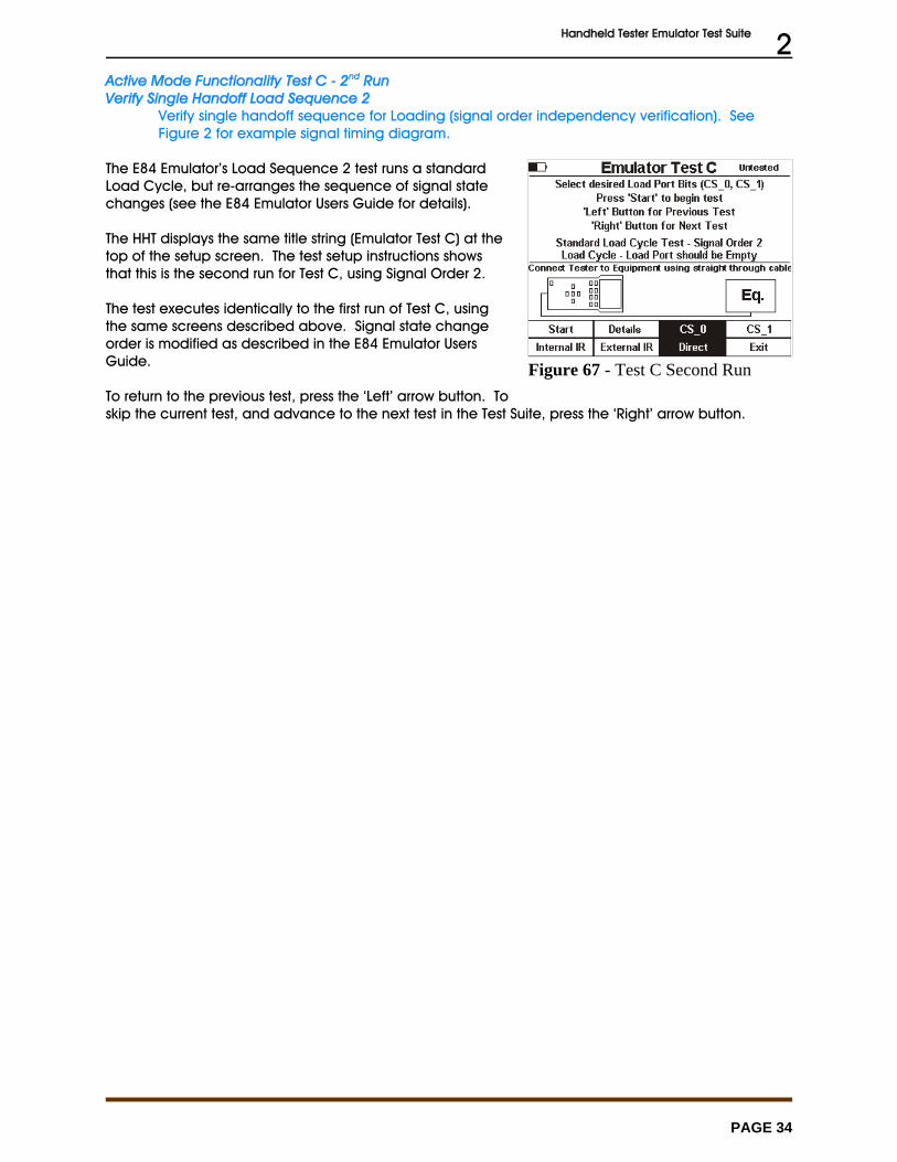
Handheld Tester Emulator Test Suite 2
PAGE 34
Figure 67 - Test C Second Run
Active Mode Functionality Test C - 2nd RunVerify Single Handoff Load Sequence 2
Verify single handoff sequence for Loading (signal order independency verification). SeeFigure 2 for example signal timing diagram.
The E84 Emulator’s Load Sequence 2 test runs a standardLoad Cycle, but re-arranges the sequence of signal statechanges (see the E84 Emulator Users Guide for details).
The HHT displays the same title string (Emulator Test C) at thetop of the setup screen. The test setup instructions showsthat this is the second run for Test C, using Signal Order 2.
The test executes identically to the first run of Test C, usingthe same screens described above. Signal state changeorder is modified as described in the E84 Emulator UsersGuide.
To return to the previous test, press the ‘Left’ arrow button. Toskip the current test, and advance to the next test in the Test Suite, press the ‘Right’ arrow button.
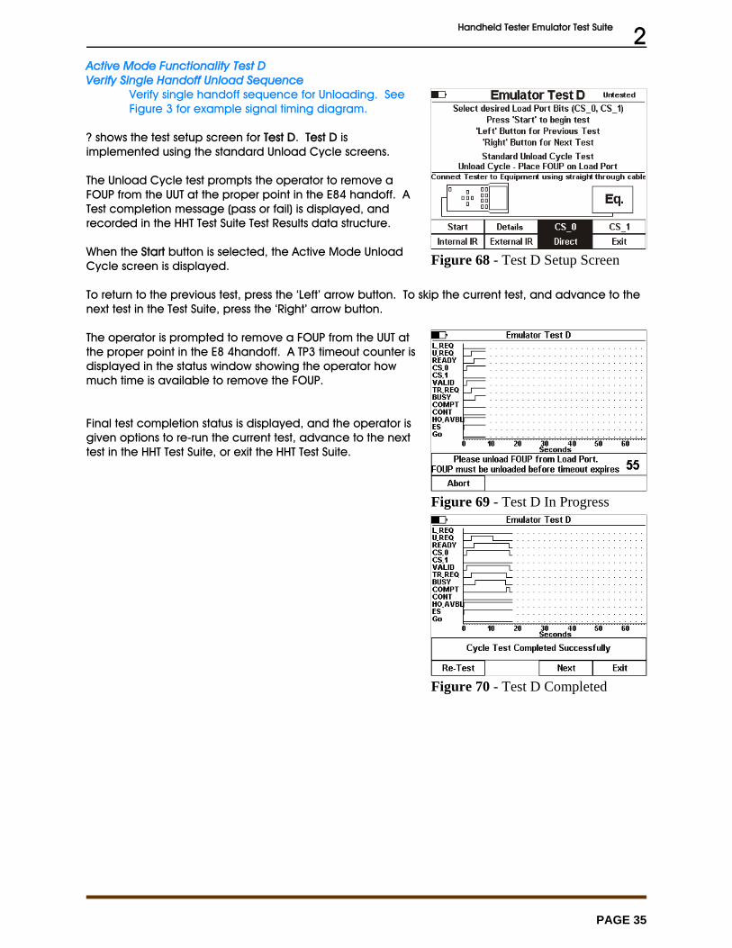
Handheld Tester Emulator Test Suite 2
PAGE 35
Figure 68 - Test D Setup Screen
Figure 69 - Test D In Progress
Figure 70 - Test D Completed
Active Mode Functionality Test DVerify Single Handoff Unload Sequence
Verify single handoff sequence for Unloading. SeeFigure 3 for example signal timing diagram.
? shows the test setup screen for Test D. Test D isimplemented using the standard Unload Cycle screens.
The Unload Cycle test prompts the operator to remove aFOUP from the UUT at the proper point in the E84 handoff. ATest completion message (pass or fail) is displayed, andrecorded in the HHT Test Suite Test Results data structure.
When the Start button is selected, the Active Mode UnloadCycle screen is displayed.
To return to the previous test, press the ‘Left’ arrow button. To skip the current test, and advance to thenext test in the Test Suite, press the ‘Right’ arrow button.
The operator is prompted to remove a FOUP from the UUT atthe proper point in the E8 4handoff. A TP3 timeout counter isdisplayed in the status window showing the operator howmuch time is available to remove the FOUP.
Final test completion status is displayed, and the operator isgiven options to re-run the current test, advance to the nexttest in the HHT Test Suite, or exit the HHT Test Suite.
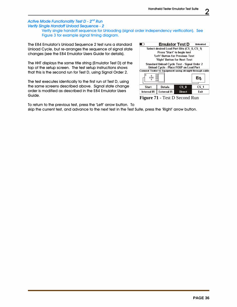
Handheld Tester Emulator Test Suite 2
PAGE 36
Figure 71 - Test D Second Run
Active Mode Functionality Test D - 2nd RunVerify Single Handoff Unload Sequence - 2
Verify single handoff sequence for Unloading (signal order independency verification). SeeFigure 3 for example signal timing diagram.
The E84 Emulator’s Unload Sequence 2 test runs a standardUnload Cycle, but re-arranges the sequence of signal statechanges (see the E84 Emulator Users Guide for details).
The HHT displays the same title string (Emulator Test D) at thetop of the setup screen. The test setup instructions showsthat this is the second run for Test D, using Signal Order 2.
The test executes identically to the first run of Test D, usingthe same screens described above. Signal state changeorder is modified as described in the E84 Emulator UsersGuide.
To return to the previous test, press the ‘Left’ arrow button. Toskip the current test, and advance to the next test in the Test Suite, press the ‘Right’ arrow button.
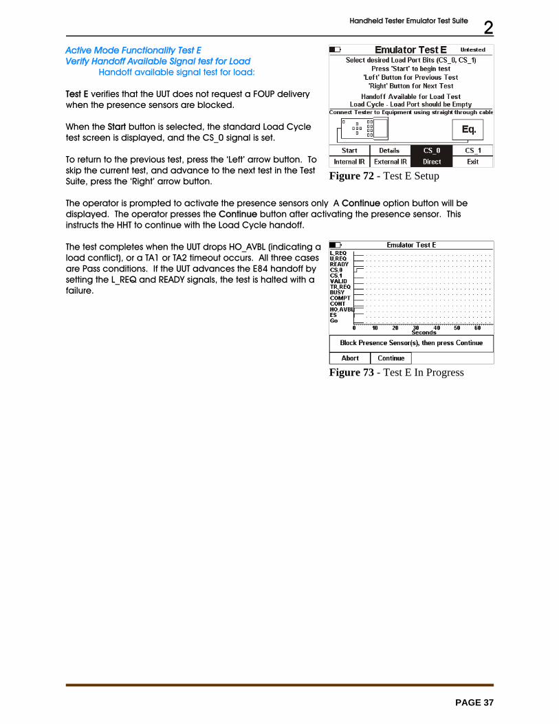
Handheld Tester Emulator Test Suite 2
PAGE 37
Figure 72 - Test E Setup
Figure 73 - Test E In Progress
Active Mode Functionality Test EVerify Handoff Available Signal test for Load
Handoff available signal test for load:
Test E verifies that the UUT does not request a FOUP deliverywhen the presence sensors are blocked.
When the Start button is selected, the standard Load Cycletest screen is displayed, and the CS_0 signal is set.
To return to the previous test, press the ‘Left’ arrow button. Toskip the current test, and advance to the next test in the TestSuite, press the ‘Right’ arrow button.
The operator is prompted to activate the presence sensors only A Continue option button will be displayed. The operator presses the Continue button after activating the presence sensor. Thisinstructs the HHT to continue with the Load Cycle handoff.
The test completes when the UUT drops HO_AVBL (indicating aload conflict), or a TA1 or TA2 timeout occurs. All three casesare Pass conditions. If the UUT advances the E84 handoff bysetting the L_REQ and READY signals, the test is halted with afailure.
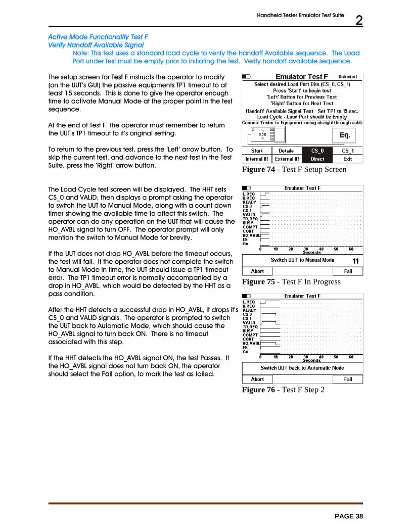
Handheld Tester Emulator Test Suite 2
PAGE 38
Figure 74 - Test F Setup Screen
Figure 75 - Test F In Progress
Figure 76 - Test F Step 2
Active Mode Functionality Test FVerify Handoff Available Signal
Note: This test uses a standard load cycle to verify the Handoff Available sequence. The LoadPort under test must be empty prior to initiating the test. Verify handoff available sequence.
The setup screen for Test F instructs the operator to modify(on the UUT’s GUI) the passive equipments TP1 timeout to atleast 15 seconds. This is done to give the operator enoughtime to activate Manual Mode at the proper point in the testsequence.
At the end of Test F, the operator must remember to returnthe UUT’s TP1 timeout to it’s original setting.
To return to the previous test, press the ‘Left’ arrow button. Toskip the current test, and advance to the next test in the TestSuite, press the ‘Right’ arrow button.
The Load Cycle test screen will be displayed. The HHT setsCS_0 and VALID, then displays a prompt asking the operatorto switch the UUT to Manual Mode, along with a count downtimer showing the available time to affect this switch. Theoperator can do any operation on the UUT that will cause theHO_AVBL signal to turn OFF. The operator prompt will onlymention the switch to Manual Mode for brevity.
If the UUT does not drop HO_AVBL before the timeout occurs,the test will fail. If the operator does not complete the switchto Manual Mode in time, the UUT should issue a TP1 timeouterror. The TP1 timeout error is normally accompanied by adrop in HO_AVBL, which would be detected by the HHT as apass condition.
After the HHT detects a successful drop in HO_AVBL, it drops it’sCS_0 and VALID signals. The operator is prompted to switchthe UUT back to Automatic Mode, which should cause theHO_AVBL signal to turn back ON. There is no timeoutassociated with this step.
If the HHT detects the HO_AVBL signal ON, the test Passes. Ifthe HO_AVBL signal does not turn back ON, the operatorshould select the Fail option, to mark the test as failed.
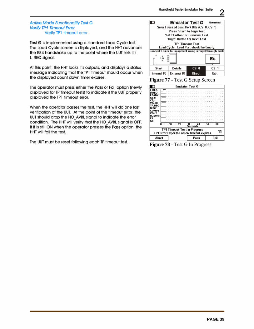
Handheld Tester Emulator Test Suite 2
PAGE 39
Figure 77 - Test G Setup Screen
Figure 78 - Test G In Progress
Active Mode Functionality Test GVerify TP1 Timeout Error
Verify TP1 timeout error.
Test G is implemented using a standard Load Cycle test. The Load Cycle screen is displayed, and the HHT advancesthe E84 handshake up to the point where the UUT sets it’sL_REQ signal.
At this point, the HHT locks it’s outputs, and displays a statusmessage indicating that the TP1 timeout should occur whenthe displayed count down timer expires.
The operator must press either the Pass or Fail option (newlydisplayed for TP timeout tests) to indicate if the UUT properlydisplayed the TP1 timeout error.
When the operator passes the test, the HHT will do one lastverification of the UUT. At the point of the timeout error, theUUT should drop the HO_AVBL signal to indicate the errorcondition. The HHT will verify that the HO_AVBL signal is OFF. If it is still ON when the operator presses the Pass option, theHHT will fail the test.
The UUT must be reset following each TP timeout test.
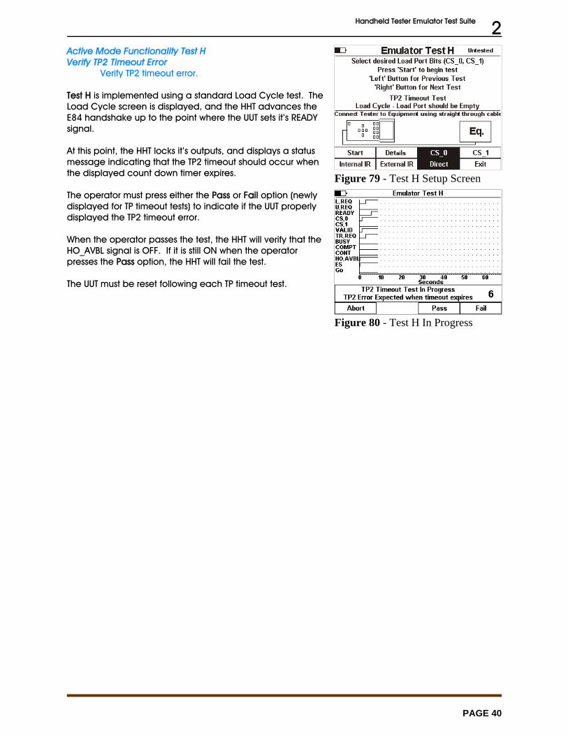
Handheld Tester Emulator Test Suite 2
PAGE 40
Figure 79 - Test H Setup Screen
Figure 80 - Test H In Progress
Active Mode Functionality Test HVerify TP2 Timeout Error
Verify TP2 timeout error.
Test H is implemented using a standard Load Cycle test. TheLoad Cycle screen is displayed, and the HHT advances theE84 handshake up to the point where the UUT sets it’s READYsignal.
At this point, the HHT locks it’s outputs, and displays a statusmessage indicating that the TP2 timeout should occur whenthe displayed count down timer expires.
The operator must press either the Pass or Fail option (newlydisplayed for TP timeout tests) to indicate if the UUT properlydisplayed the TP2 timeout error.
When the operator passes the test, the HHT will verify that theHO_AVBL signal is OFF. If it is still ON when the operatorpresses the Pass option, the HHT will fail the test.
The UUT must be reset following each TP timeout test.

Handheld Tester Emulator Test Suite 2
PAGE 41
Figure 81 - Test I Setup Screen
Figure 82 - Test I In Progress
Active Mode Functionality Test IVerify TP3 Timeout Error
Verify TP3 timeout error.
Test I is implemented using a standard Load Cycle test. TheLoad Cycle screen is displayed, and the HHT advances theE84 handshake up to the point where the UUT is waiting forthe delivery of a FOUP.
At this point, a normal Load Cycle would place the FOUPonto the UUT. Instead, the operator waits for the TP3 timeoutto occur. The HHT displays a status message indicating thatthe TP3 timeout should occur when the displayed countdown timer expires.
The operator must press either the Pass or Fail option (newlydisplayed for TP timeout tests) to indicate if the UUT properlydisplayed the TP3 timeout error.
When the operator passes the test, the HHT will verify that theHO_AVBL signal is OFF. If it is still ON when the operatorpresses the Pass option, the HHT will fail the test.
The UUT must be reset following each TP timeout test.
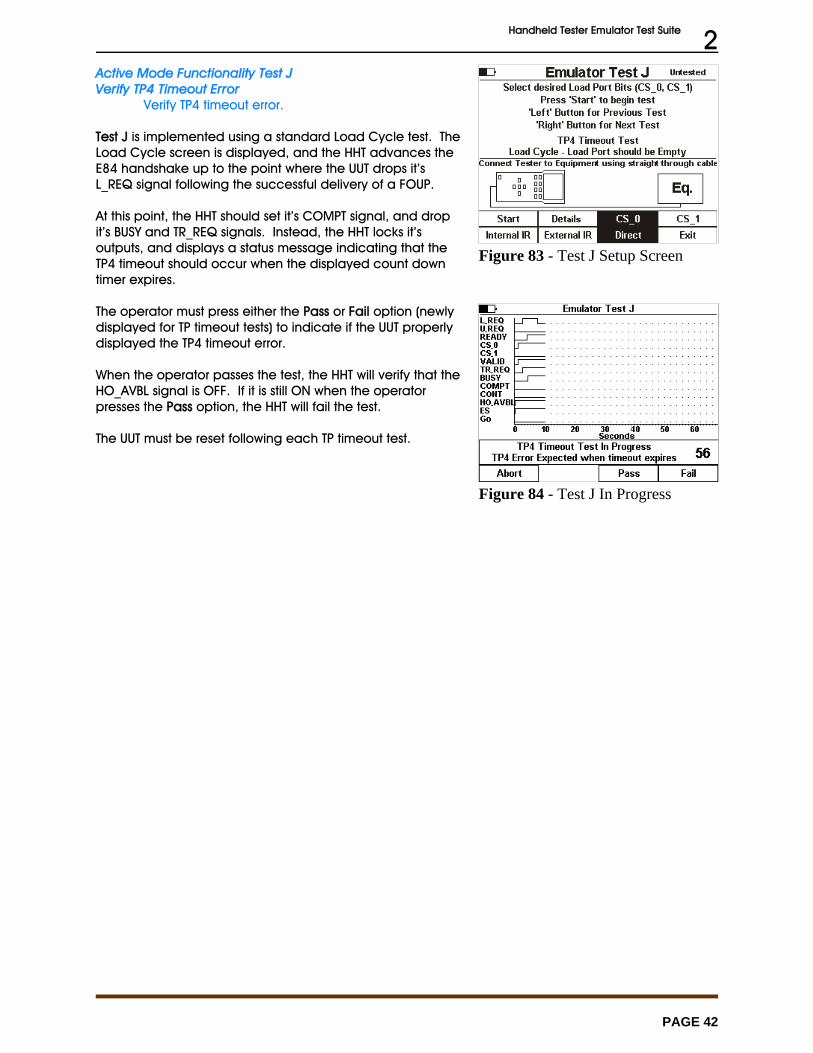
Handheld Tester Emulator Test Suite 2
PAGE 42
Figure 83 - Test J Setup Screen
Figure 84 - Test J In Progress
Active Mode Functionality Test JVerify TP4 Timeout Error
Verify TP4 timeout error.
Test J is implemented using a standard Load Cycle test. TheLoad Cycle screen is displayed, and the HHT advances theE84 handshake up to the point where the UUT drops it’sL_REQ signal following the successful delivery of a FOUP.
At this point, the HHT should set it’s COMPT signal, and dropit’s BUSY and TR_REQ signals. Instead, the HHT locks it’soutputs, and displays a status message indicating that theTP4 timeout should occur when the displayed count downtimer expires.
The operator must press either the Pass or Fail option (newlydisplayed for TP timeout tests) to indicate if the UUT properlydisplayed the TP4 timeout error.
When the operator passes the test, the HHT will verify that theHO_AVBL signal is OFF. If it is still ON when the operatorpresses the Pass option, the HHT will fail the test.
The UUT must be reset following each TP timeout test.
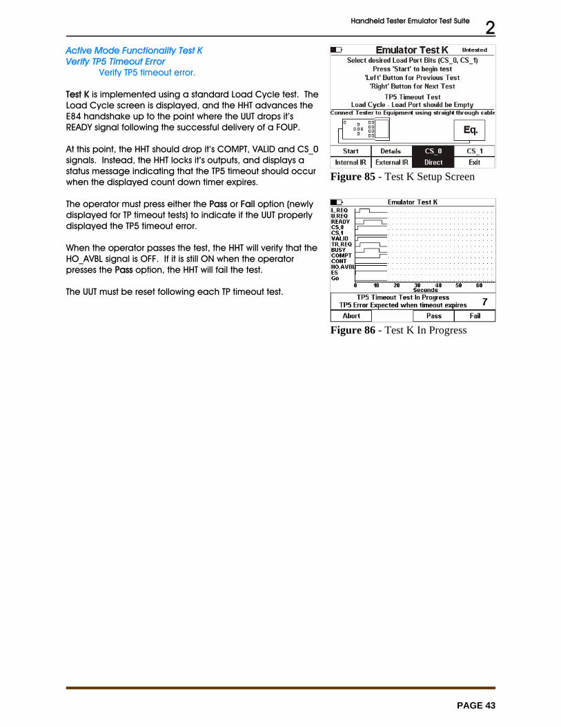
Handheld Tester Emulator Test Suite 2
PAGE 43
Figure 85 - Test K Setup Screen
Figure 86 - Test K In Progress
Active Mode Functionality Test KVerify TP5 Timeout Error
Verify TP5 timeout error.
Test K is implemented using a standard Load Cycle test. TheLoad Cycle screen is displayed, and the HHT advances theE84 handshake up to the point where the UUT drops it’sREADY signal following the successful delivery of a FOUP.
At this point, the HHT should drop it’s COMPT, VALID and CS_0signals. Instead, the HHT locks it’s outputs, and displays astatus message indicating that the TP5 timeout should occurwhen the displayed count down timer expires.
The operator must press either the Pass or Fail option (newlydisplayed for TP timeout tests) to indicate if the UUT properlydisplayed the TP5 timeout error.
When the operator passes the test, the HHT will verify that theHO_AVBL signal is OFF. If it is still ON when the operatorpresses the Pass option, the HHT will fail the test.
The UUT must be reset following each TP timeout test.
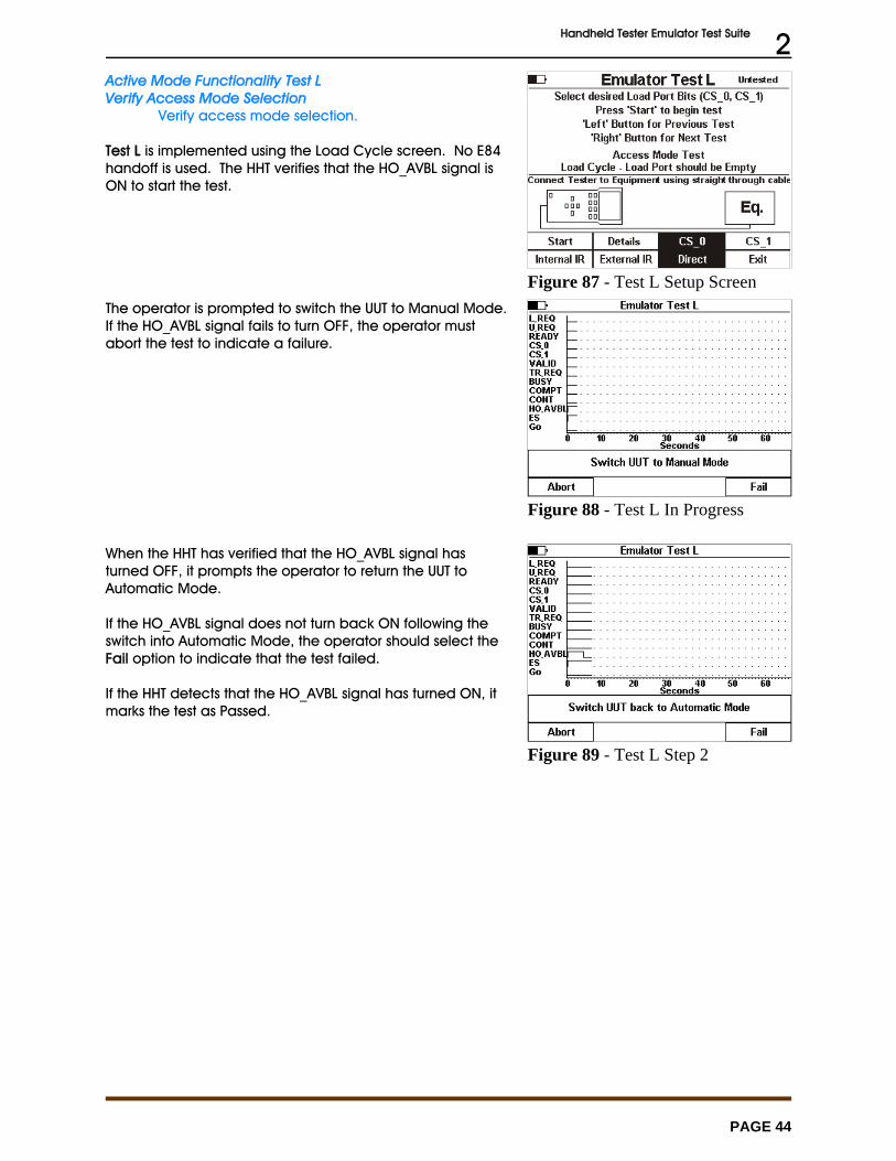
Handheld Tester Emulator Test Suite 2
PAGE 44
Figure 87 - Test L Setup Screen
Figure 88 - Test L In Progress
Figure 89 - Test L Step 2
Active Mode Functionality Test LVerify Access Mode Selection
Verify access mode selection.
Test L is implemented using the Load Cycle screen. No E84handoff is used. The HHT verifies that the HO_AVBL signal isON to start the test.
The operator is prompted to switch the UUT to Manual Mode. If the HO_AVBL signal fails to turn OFF, the operator mustabort the test to indicate a failure.
When the HHT has verified that the HO_AVBL signal hasturned OFF, it prompts the operator to return the UUT toAutomatic Mode.
If the HO_AVBL signal does not turn back ON following theswitch into Automatic Mode, the operator should select theFail option to indicate that the test failed.
If the HHT detects that the HO_AVBL signal has turned ON, itmarks the test as Passed.
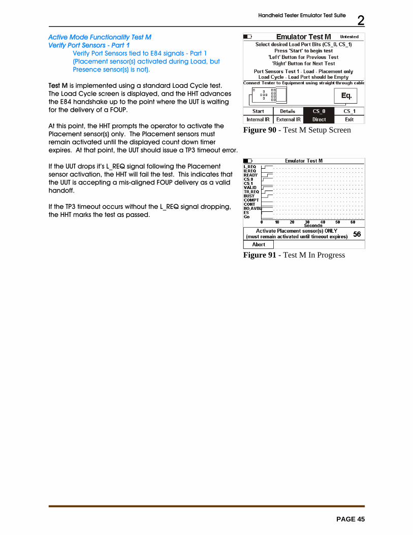
Handheld Tester Emulator Test Suite 2
PAGE 45
Figure 90 - Test M Setup Screen
Figure 91 - Test M In Progress
Active Mode Functionality Test MVerify Port Sensors - Part 1
Verify Port Sensors tied to E84 signals - Part 1(Placement sensor(s) activated during Load, butPresence sensor(s) is not).
Test M is implemented using a standard Load Cycle test. The Load Cycle screen is displayed, and the HHT advancesthe E84 handshake up to the point where the UUT is waitingfor the delivery of a FOUP.
At this point, the HHT prompts the operator to activate thePlacement sensor(s) only. The Placement sensors mustremain activated until the displayed count down timerexpires. At that point, the UUT should issue a TP3 timeout error.
If the UUT drops it’s L_REQ signal following the Placementsensor activation, the HHT will fail the test. This indicates thatthe UUT is accepting a mis-aligned FOUP delivery as a validhandoff.
If the TP3 timeout occurs without the L_REQ signal dropping,the HHT marks the test as passed.
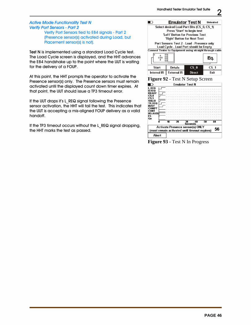
Handheld Tester Emulator Test Suite 2
PAGE 46
Figure 92 - Test N Setup Screen
Figure 93 - Test N In Progress
Active Mode Functionality Test NVerify Port Sensors - Part 2
Verify Port Sensors tied to E84 signals - Part 2(Presence sensor(s) activated during Load, butPlacement sensor(s) is not).
Test N is implemented using a standard Load Cycle test. The Load Cycle screen is displayed, and the HHT advancesthe E84 handshake up to the point where the UUT is waitingfor the delivery of a FOUP.
At this point, the HHT prompts the operator to activate thePresence sensor(s) only. The Presence sensors must remainactivated until the displayed count down timer expires. Atthat point, the UUT should issue a TP3 timeout error.
If the UUT drops it’s L_REQ signal following the Presencesensor activation, the HHT will fail the test. This indicates thatthe UUT is accepting a mis-aligned FOUP delivery as a validhandoff.
If the TP3 timeout occurs without the L_REQ signal dropping,the HHT marks the test as passed.
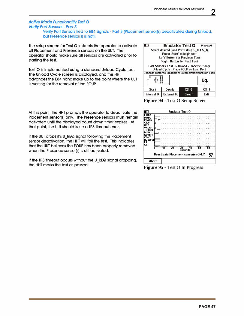
Handheld Tester Emulator Test Suite 2
PAGE 47
Figure 94 - Test O Setup Screen
Figure 95 - Test O In Progress
Active Mode Functionality Test OVerify Port Sensors - Part 3
Verify Port Sensors tied to E84 signals - Part 3 (Placement sensor(s) deactivated during Unload,but Presence sensor(s) is not).
The setup screen for Test O instructs the operator to activateall Placement and Presence sensors on the UUT. Theoperator should make sure all sensors are activated prior tostarting the test.
Test O is implemented using a standard Unload Cycle test. The Unload Cycle screen is displayed, and the HHTadvances the E84 handshake up to the point where the UUTis waiting for the removal of the FOUP.
At this point, the HHT prompts the operator to deactivate thePlacement sensor(s) only. The Presence sensors must remainactivated until the displayed count down timer expires. Atthat point, the UUT should issue a TP3 timeout error.
If the UUT drops it’s U_REQ signal following the Placementsensor deactivation, the HHT will fail the test. This indicatesthat the UUT believes the FOUP has been properly removedwhen the Presence sensor(s) is still activated.
If the TP3 timeout occurs without the U_REQ signal dropping,the HHT marks the test as passed.
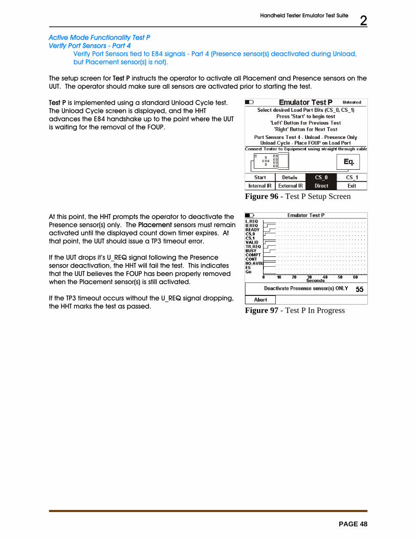
Handheld Tester Emulator Test Suite 2
PAGE 48
Figure 96 - Test P Setup Screen
Figure 97 - Test P In Progress
Active Mode Functionality Test PVerify Port Sensors - Part 4
Verify Port Sensors tied to E84 signals - Part 4 (Presence sensor(s) deactivated during Unload,but Placement sensor(s) is not).
The setup screen for Test P instructs the operator to activate all Placement and Presence sensors on theUUT. The operator should make sure all sensors are activated prior to starting the test.
Test P is implemented using a standard Unload Cycle test. The Unload Cycle screen is displayed, and the HHTadvances the E84 handshake up to the point where the UUTis waiting for the removal of the FOUP.
At this point, the HHT prompts the operator to deactivate thePresence sensor(s) only. The Placement sensors must remainactivated until the displayed count down timer expires. Atthat point, the UUT should issue a TP3 timeout error.
If the UUT drops it’s U_REQ signal following the Presencesensor deactivation, the HHT will fail the test. This indicatesthat the UUT believes the FOUP has been properly removedwhen the Placement sensor(s) is still activated.
If the TP3 timeout occurs without the U_REQ signal dropping,the HHT marks the test as passed.
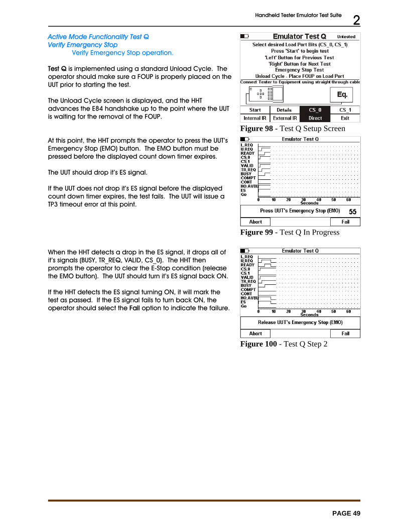
Handheld Tester Emulator Test Suite 2
PAGE 49
Figure 98 - Test Q Setup Screen
Figure 99 - Test Q In Progress
Figure 100 - Test Q Step 2
Active Mode Functionality Test QVerify Emergency Stop
Verify Emergency Stop operation.
Test Q is implemented using a standard Unload Cycle. Theoperator should make sure a FOUP is properly placed on theUUT prior to starting the test.
The Unload Cycle screen is displayed, and the HHTadvances the E84 handshake up to the point where the UUTis waiting for the removal of the FOUP.
At this point, the HHT prompts the operator to press the UUT’sEmergency Stop (EMO) button. The EMO button must bepressed before the displayed count down timer expires.
The UUT should drop it’s ES signal.
If the UUT does not drop it’s ES signal before the displayedcount down timer expires, the test fails. The UUT will issue aTP3 timeout error at this point.
When the HHT detects a drop in the ES signal, it drops all ofit’s signals (BUSY, TR_REQ, VALID, CS_0). The HHT thenprompts the operator to clear the E-Stop condition (releasethe EMO button). The UUT should turn it’s ES signal back ON.
If the HHT detects the ES signal turning ON, it will mark thetest as passed. If the ES signal fails to turn back ON, theoperator should select the Fail option to indicate the failure.
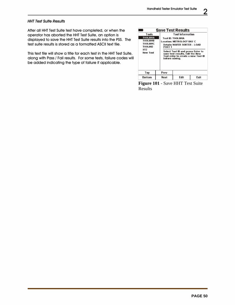
Handheld Tester Emulator Test Suite 2
PAGE 50
Figure 101 - Save HHT Test SuiteResults
HHT Test Suite Results
After all HHT Test Suite test have completed, or when theoperator has aborted the HHT Test Suite, an option isdisplayed to save the HHT Test Suite results into the PSS. Thetest suite results is stored as a formatted ASCII text file.
This text file will show a title for each test in the HHT Test Suite,along with Pass / Fail results. For some tests, failure codes willbe added indicating the type of failure if applicable.

Get Control, Inc.
E84 Handheld TesterGCI05001
Emulator Test Suite Worksheet
March 1, 2006

Tests C and D will be tested twice to verify the equipment does not require a specific order ofsignals at the transfer complete and release of CS sequences of the E84 handoff.
When loading a FOUP during Test C, the FOUP should be loaded such that the placementsensor is blocked approximately 5 seconds after the presence sensor (where possible).
When unloading a FOUP during Test D, the FOUP should be unloaded such that the presencesensor is unblocked approximately 5 seconds after the placement sensor (where possible).
HHT Test Suite Worksheet
This section provides a test worksheet for use while running HHT Test Suite tests. It includes details foreach test in the HHT Test Suite, along with user comment fields. The HHT does not provide a method ofentering test related comments. This worksheet is intended to be used during HHT Test Suite testing,and provides a manual method for recording test related comments.
Instrumentation, Tools, Other
• 1 person (3 hrs)• tape measure• metric scale• E84 HHT• this HHT Test Suite Worksheet
Setup Procedure
The unit under test (UUT) must be fully assembled as for normal operation with power applied. The E84HHT must be set to run the Emulator Test Suite (select option 1 - Standard Cycle Test from Main TestMenu, then option 5 - Emulator Test Suite).
Active Mode Static Tests
Ensure that E84 parallel I/O interface plug(s) are mounted on the top of the equipment per SEMI* E84. Ensure 1 plug is provided for each equipment load port. Ensure that documented recoveryprocedures exist per SEMI* E84.
Active Mode Functionality Tests
Ensure functionality of the E84 interface device per the SEMI* E84 standard.
Handheld Tester Emulator Test Suite Worksheet 3
PAGE 54
[P] [F] A. Using the equipment user interface, verify that the passive equipment timers (TP1 throughTP5) are configurable within the range specified in E84 (1 to 999) and make note of thedefault settings.
Use the HHT’s Tester Configuration (option 7 of Main Test Menu) to enter the passiveequipment timers into the HHT:
TP1 _______seconds
TP2 _______seconds
TP3 _______seconds
TP4 _______seconds
TP5 _______seconds
Notes:
[P] [F] B. Verify for hard wired implementation the voltage provided by the unit under test (UUT) iswithin the range specified in E84 under Full Load [100mA] and No Load [<2mA]. Bothmeasurements must be within the published range to pass.
UUT supplies voltage on Pin 23 of the E84 Interface.
1. Voltage at Full Load is in the range of 18VDC to 30VDC2. Voltage at No Load is in the range of 18VDC to 30VDC
Also note voltage measured on Pin 22. This voltage should also fall within the publishedrange. A voltage measurement on Pin 22 that is less than 18 VDC implies an improperlywired E84 interface.
Notes:
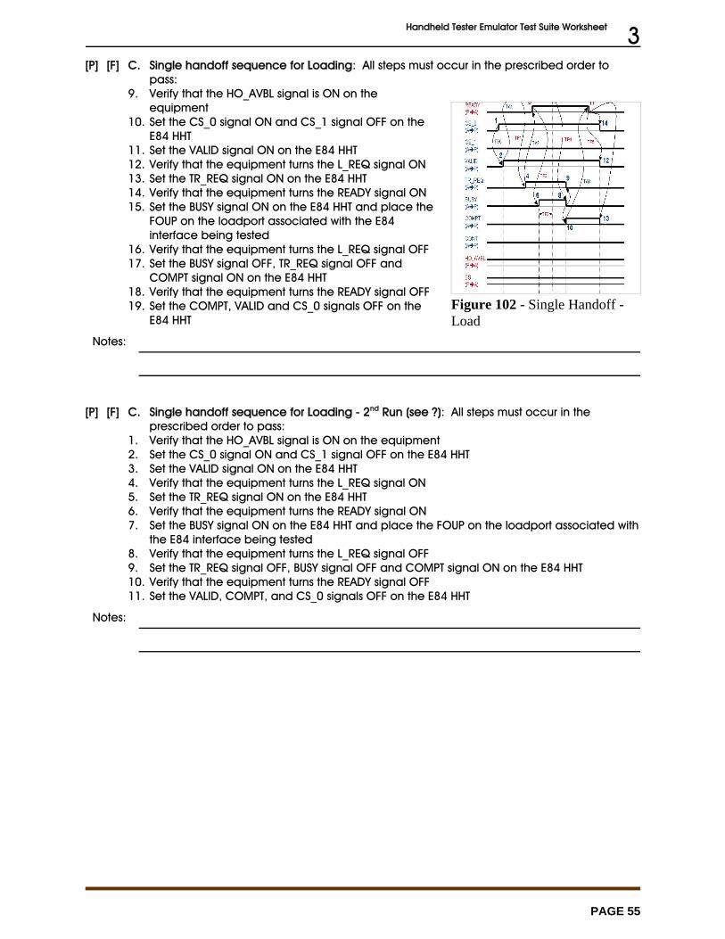
Handheld Tester Emulator Test Suite Worksheet 3
PAGE 55
Figure 102 - Single Handoff -Load
[P] [F] C. Single handoff sequence for Loading: All steps must occur in the prescribed order topass:
9. Verify that the HO_AVBL signal is ON on theequipment
10. Set the CS_0 signal ON and CS_1 signal OFF on theE84 HHT
11. Set the VALID signal ON on the E84 HHT12. Verify that the equipment turns the L_REQ signal ON13. Set the TR_REQ signal ON on the E84 HHT14. Verify that the equipment turns the READY signal ON15. Set the BUSY signal ON on the E84 HHT and place the
FOUP on the loadport associated with the E84interface being tested
16. Verify that the equipment turns the L_REQ signal OFF17. Set the BUSY signal OFF, TR_REQ signal OFF and
COMPT signal ON on the E84 HHT18. Verify that the equipment turns the READY signal OFF19. Set the COMPT, VALID and CS_0 signals OFF on the
E84 HHT
Notes:
[P] [F] C. Single handoff sequence for Loading - 2nd Run (see ?): All steps must occur in theprescribed order to pass:
1. Verify that the HO_AVBL signal is ON on the equipment2. Set the CS_0 signal ON and CS_1 signal OFF on the E84 HHT3. Set the VALID signal ON on the E84 HHT4. Verify that the equipment turns the L_REQ signal ON5. Set the TR_REQ signal ON on the E84 HHT6. Verify that the equipment turns the READY signal ON7. Set the BUSY signal ON on the E84 HHT and place the FOUP on the loadport associated with
the E84 interface being tested8. Verify that the equipment turns the L_REQ signal OFF9. Set the TR_REQ signal OFF, BUSY signal OFF and COMPT signal ON on the E84 HHT10. Verify that the equipment turns the READY signal OFF11. Set the VALID, COMPT, and CS_0 signals OFF on the E84 HHT
Notes:

Handheld Tester Emulator Test Suite Worksheet 3
PAGE 56
Figure 103 - Single Handoff -Unload
[P] [F] D. Single handoff sequence for Unloading: All steps must occur in the prescribed order topass:
1. Place a FOUP on the loadport associated with the E84interface being tested
2. Verify that the HO_AVBL signal is ON on the equipment3. Set the CS_0 signal ON and CS_1 signal OFF on the E84
HHT4. Set the VALID signal ON on the E84 HHT5. Verify that the equipment turns the U_REQ signal ON6. Set the TR_REQ signal ON on the E84 HHT7. Verify that the equipment turns the READY signal ON8. Set the BUSY signal ON on the E84 HHT and remove the
FOUP from the loadport associated with the E84interface being tested
9. Verify that the equipment turns the U_REQ signal OFF10. Set the BUSY signal OFF, TR_REQ signal OFF and COMPT
signal ON on the E84 HHT11. Verify that the equipment turns the READY signal OFF12. Set the COMPT, VALID and CS_0 signals OFF on the E84
HHT
Notes:
[P] [F] D. Single handoff sequence for Unloading - 2nd Run (See ?): All steps must occur in theprescribed order to pass:
1. Place a FOUP on the loadport associated with the E84 interface being tested2. Verify that the HO_AVBL signal is ON on the equipment3. Set the CS_0 signal ON and CS_1 signal OFF on the E84 HHT4. Set the VALID signal ON on the E84 HHT5. Verify that the equipment turns the U_REQ signal ON6. Set the TR_REQ signal ON on the E84 HHT7. Verify that the equipment turns the READY signal ON8. Set the BUSY signal ON on the E84 HHT and remove the FOUP from the loadport associated
with the E84 interface being tested9. Verify that the equipment turns the U_REQ signal OFF10. Set the TR_REQ signal OFF, BUSY signal OFF and COMPT signal ON on the E84 HHT11. Verify that the equipment turns the READY signal OFF12. Set the COMPT, CS_0 and VALID signals OFF on the E84 HHT
Notes:
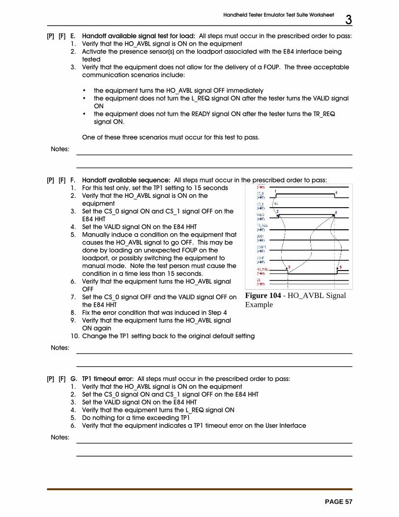
Handheld Tester Emulator Test Suite Worksheet 3
PAGE 57
Figure 104 - HO_AVBL SignalExample
[P] [F] E. Handoff available signal test for load: All steps must occur in the prescribed order to pass:1. Verify that the HO_AVBL signal is ON on the equipment2. Activate the presence sensor(s) on the loadport associated with the E84 interface being
tested3. Verify that the equipment does not allow for the delivery of a FOUP. The three acceptable
communication scenarios include:
• the equipment turns the HO_AVBL signal OFF immediately• the equipment does not turn the L_REQ signal ON after the tester turns the VALID signal
ON• the equipment does not turn the READY signal ON after the tester turns the TR_REQ
signal ON.
One of these three scenarios must occur for this test to pass.
Notes:
[P] [F] F. Handoff available sequence: All steps must occur in the prescribed order to pass:1. For this test only, set the TP1 setting to 15 seconds2. Verify that the HO_AVBL signal is ON on the
equipment3. Set the CS_0 signal ON and CS_1 signal OFF on the
E84 HHT4. Set the VALID signal ON on the E84 HHT5. Manually induce a condition on the equipment that
causes the HO_AVBL signal to go OFF. This may bedone by loading an unexpected FOUP on theloadport, or possibly switching the equipment tomanual mode. Note the test person must cause thecondition in a time less than 15 seconds.
6. Verify that the equipment turns the HO_AVBL signalOFF
7. Set the CS_0 signal OFF and the VALID signal OFF onthe E84 HHT
8. Fix the error condition that was induced in Step 49. Verify that the equipment turns the HO_AVBL signal
ON again 10. Change the TP1 setting back to the original default setting
Notes:
[P] [F] G. TP1 timeout error: All steps must occur in the prescribed order to pass:1. Verify that the HO_AVBL signal is ON on the equipment2. Set the CS_0 signal ON and CS_1 signal OFF on the E84 HHT3. Set the VALID signal ON on the E84 HHT4. Verify that the equipment turns the L_REQ signal ON5. Do nothing for a time exceeding TP16. Verify that the equipment indicates a TP1 timeout error on the User Interface
Notes:
Handheld Tester Emulator Test Suite Worksheet 3
PAGE 58
[P] [F] H. TP2 timeout error: All steps must occur in the prescribed order to pass:1. Verify that the HO_AVBL signal is ON on the equipment2. Set the CS_0 signal ON and CS_1 signal OFF on the E84 HHT3. Set the VALID signal ON on the E84 HHT4. Verify that the equipment turns the L_REQ signal ON5. Set the TR_REQ signal ON on the E84 HHT6. Verify that the equipment turns the READY signal ON7. Do nothing for a time exceeding TP28. Verify that the equipment indicates a TP2 timeout error on the User Interface
Notes:
[P] [F] I. TP3 timeout error: All steps must occur in the prescribed order to pass:1. Verify that the HO_AVBL signal is ON on the equipment2. Set the CS_0 signal ON and CS_1 signal OFF on the E84 HHT3. Set the VALID signal ON on the E84 HHT4. Verify that the equipment turns the L_REQ signal ON5. Set the TR_REQ signal ON on the E84 HHT6. Verify that the equipment turns the READY signal ON7. Set the BUSY signal ON on the E84 HHT but DO NOT place the FOUP on the loadport for a
time exceeding TP38. Verify that the equipment indicates a TP3 timeout error on the User Interface
Notes:
[P] [F] J. TP4 timeout error: All steps must occur in the prescribed order to pass:1. Verify that the HO_AVBL signal is ON on the equipment2. Set the CS_0 signal ON and CS_1 signal OFF on the E84 HHT3. Set the VALID signal ON on the E84 HHT4. Verify that the equipment turns the L_REQ signal ON5. Set the TR_REQ signal ON on the E84 HHT6. Verify that the equipment turns the READY signal ON7. Set the BUSY signal ON on the E84 HHT and place the FOUP on the loadport associated with
the E84 interface being tested8. Verify that the equipment turns the L_REQ signal OFF9. Do nothing for a time exceeding TP410. Verify that the equipment indicates a TP4 timeout error on the User Interface
Notes:
Handheld Tester Emulator Test Suite Worksheet 3
PAGE 59
[P] [F] K. TP5 timeout error: All steps must occur in the prescribed order to pass:1. Verify that the HO_AVBL signal is ON on the equipment2. Set the CS_0 signal ON and CS_1 signal OFF on the E84 HHT3. Set the VALID signal ON on the E84 HHT4. Verify that the equipment turns the L_REQ signal ON5. Set the TR_REQ signal ON on the E84 HHT6. Verify that the equipment turns the READY signal ON7. Set the BUSY signal ON on the E84 HHT and place the FOUP on the loadport associated with
the E84 interface being tested8. Verify that the equipment turns the L_REQ signal OFF9. Set the BUSY signal OFF, TR_REQ signal OFF and COMPT signal ON on the E84 HHT10. Verify that the equipment turns the READY signal OFF11. Do nothing for a time exceeding TP512. Verify that the equipment indicates a TP5 timeout error on the User Interface
Notes:
[P] [F] L. Access mode test: All steps must occur in the prescribed order to pass:1. Verify that the HO_AVBL signal is ON on the equipment2. Place the equipment into manual access mode using the equipment user interface. Note:
the equipment should also have this functionality using the host instead of the userinterface, but this is not part of the test plan.
3. Verify that the HO_AVBL signal is OFF4. Place the equipment into automated access mode using the equipment user interface. 5. Verify that the HO_AVBL signal is ON
Notes:
[P] [F] M. Port sensors tied into E84 signals part 1 - Placement sensor(s)activated during Load, butpresence sensor(s) is not: All steps must occur in the prescribed order to pass:
1. Verify that the HO_AVBL signal is ON on the equipment2. Set the CS_0 signal ON and CS_1 signal OFF on the E84 HHT3. Set the VALID signal ON on the E84 HHT4. Verify that the equipment turns the L_REQ signal ON5. Set the TR_REQ signal ON on the E84 HHT6. Verify that the equipment turns the READY signal ON7. Set the BUSY signal ON on the E84 HHT and activate all of the placement sensor(s) only on
the loadport associated with the E84 interface being tested8. Verify that the equipment does NOT turn the L_REQ signal OFF9. After exceeding the TP3 time, verify that the equipment indicates a TP3 timeout error on the
User Interface
Notes:
Handheld Tester Emulator Test Suite Worksheet 3
PAGE 60
[P] [F] N. Port sensors tied into E84 signals 2 - Presence sensor(s) activated during Load, butplacement sensor(s) is not: All steps must occur in the prescribed order to pass:
1. Verify that the HO_AVBL signal is ON on the equipment2. Set the CS_0 signal ON and CS_1 signal OFF on the E84 HHT3. Set the VALID signal ON on the E84 HHT4. Verify that the equipment turns the L_REQ signal ON5. Set the TR_REQ signal ON on the E84 HHT6. Verify that the equipment turns the READY signal ON7. Set the BUSY signal ON on the E84 HHT and activate the presence sensor(s) only on the
loadport associated with the E84 interface being tested8. Verify that the equipment does NOT turn the L_REQ signal OFF9. After exceeding the TP3 time, verify that the equipment indicates a TP3 timeout error on the
User Interface
Notes:
[P] [F] O. Port sensors tied into E84 signals 3 - Placement sensor(s) deactivated during Unload, butpresence sensor(s) is not: All steps must occur in the prescribed order to pass:
1. Activate both the placement and presence sensors on the loadport associated with theE84 interface being tested
2. Verify that the HO_AVBL signal is ON on the equipment3. Set the CS_0 signal ON and CS_1 signal OFF on the E84 HHT4. Set the VALID signal ON on the E84 HHT5. Verify that the equipment turns the U_REQ signal ON6. Set the TR_REQ signal ON on the E84 HHT7. Verify that the equipment turns the READY signal ON8. Set the BUSY signal ON on the E84 HHT and deactivate the placement sensor(s) only from
the loadport associated with the E84 interface being tested9. Verify that the equipment does NOT turn the U_REQ signal OFF10. After exceeding the TP3 time, verify that the equipment indicates a TP3 timeout error on the
User Interface
Notes:
[P] [F] P. Port sensors tied into E84 signals 4 - Presence sensor(s) deactivated during Unload, butplacement sensor(s) is not: All steps must occur in the prescribed order to pass:
1. Activate both the placement and presence sensors on the loadport associated with theE84 interface being tested
2. Verify that the HO_AVBL signal is ON on the equipment3. Set the CS_0 signal ON and CS_1 signal OFF on the E84 HHT4. Set the VALID signal ON on the E84 HHT5. Verify that the equipment turns the U_REQ signal ON6. Set the TR_REQ signal ON on the E84 HHT7. Verify that the equipment turns the READY signal ON8. Set the BUSY signal ON on the E84 HHT and deactivate the presence sensor(s) only from the
loadport associated with the E84 interface being tested9. Verify that the equipment does NOT turn the U_REQ signal OFF10. After exceeding the TP3 time, verify that the equipment indicates a TP3 timeout error on the
User Interface
Notes:
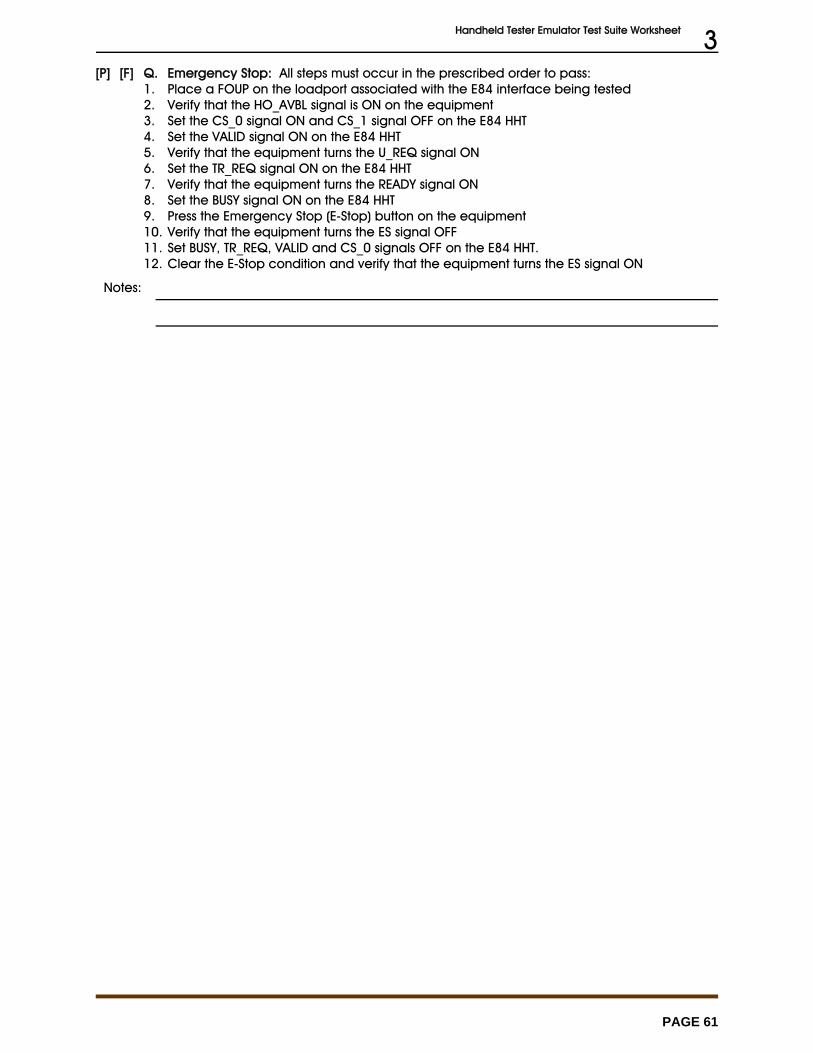
Handheld Tester Emulator Test Suite Worksheet 3
PAGE 61
[P] [F] Q. Emergency Stop: All steps must occur in the prescribed order to pass:1. Place a FOUP on the loadport associated with the E84 interface being tested2. Verify that the HO_AVBL signal is ON on the equipment3. Set the CS_0 signal ON and CS_1 signal OFF on the E84 HHT4. Set the VALID signal ON on the E84 HHT5. Verify that the equipment turns the U_REQ signal ON6. Set the TR_REQ signal ON on the E84 HHT7. Verify that the equipment turns the READY signal ON8. Set the BUSY signal ON on the E84 HHT9. Press the Emergency Stop (E-Stop) button on the equipment10. Verify that the equipment turns the ES signal OFF11. Set BUSY, TR_REQ, VALID and CS_0 signals OFF on the E84 HHT.12. Clear the E-Stop condition and verify that the equipment turns the ES signal ON
Notes:
