geothermal/water source heat pump • r-410a refrigerant • 0
TRANSCRIPT
RC
Ser
ies
Eng
inee
ring
Gui
de
Design Features
Factory Options
Accessories
Dimensional Data
Physical Data
Performance Data
Engineering Guide Specifi cations
Form: 146.04-EG1 (0317)Supercedes: 146.00-EG4 (0515)
RC SeriesCONSOLEGeothermal/Water Source Heat Pump • R-410A Refrigerant • 0.75-1.5 Ton Single Speed

RC SERIES ENGINEERING GUIDE
Model Nomenclature . . . . . . . . . . . . . . . . . . . . . . . . . . . . . . . . . . . . . . . . . . . . . . . . . . . . . . . . . . . . . . 4
AHRI Data . . . . . . . . . . . . . . . . . . . . . . . . . . . . . . . . . . . . . . . . . . . . . . . . . . . . . . . . . . . . . . . . . . . . . 5-6
The RC Series Console . . . . . . . . . . . . . . . . . . . . . . . . . . . . . . . . . . . . . . . . . . . . . . . . . . . . . . . . . . . . 7
Inside the RC Series Console . . . . . . . . . . . . . . . . . . . . . . . . . . . . . . . . . . . . . . . . . . . . . . . . . . . . . . . 8
Controls . . . . . . . . . . . . . . . . . . . . . . . . . . . . . . . . . . . . . . . . . . . . . . . . . . . . . . . . . . . . . . . . . . . . . . . . 9
Application Notes . . . . . . . . . . . . . . . . . . . . . . . . . . . . . . . . . . . . . . . . . . . . . . . . . . . . . . . . . . . . . . . . 17
Selection Example . . . . . . . . . . . . . . . . . . . . . . . . . . . . . . . . . . . . . . . . . . . . . . . . . . . . . . . . . . . . . . . 22
Dimensional Data . . . . . . . . . . . . . . . . . . . . . . . . . . . . . . . . . . . . . . . . . . . . . . . . . . . . . . . . . . . . . . . . 24
Unit Operating Limits . . . . . . . . . . . . . . . . . . . . . . . . . . . . . . . . . . . . . . . . . . . . . . . . . . . . . . . . . . . . . 31
Physical Data . . . . . . . . . . . . . . . . . . . . . . . . . . . . . . . . . . . . . . . . . . . . . . . . . . . . . . . . . . . . . . . . . . . 32
Unit Electrical Data . . . . . . . . . . . . . . . . . . . . . . . . . . . . . . . . . . . . . . . . . . . . . . . . . . . . . . . . . . . . . . 33
Auxiliary Heat Ratings . . . . . . . . . . . . . . . . . . . . . . . . . . . . . . . . . . . . . . . . . . . . . . . . . . . . . . . . . . . . 34
Fan Performance Data . . . . . . . . . . . . . . . . . . . . . . . . . . . . . . . . . . . . . . . . . . . . . . . . . . . . . . . . . . . 34
Reference Calculations . . . . . . . . . . . . . . . . . . . . . . . . . . . . . . . . . . . . . . . . . . . . . . . . . . . . . . . . . . . 35
Legends and Notes . . . . . . . . . . . . . . . . . . . . . . . . . . . . . . . . . . . . . . . . . . . . . . . . . . . . . . . . . . . . . . 35
Correction Factor Tables . . . . . . . . . . . . . . . . . . . . . . . . . . . . . . . . . . . . . . . . . . . . . . . . . . . . . . . . . . 36
Capacity Data. . . . . . . . . . . . . . . . . . . . . . . . . . . . . . . . . . . . . . . . . . . . . . . . . . . . . . . . . . . . . . . . . . . 37
Wiring Schematics . . . . . . . . . . . . . . . . . . . . . . . . . . . . . . . . . . . . . . . . . . . . . . . . . . . . . . . . . . . . . . . 41
Engineering Guide Specifications. . . . . . . . . . . . . . . . . . . . . . . . . . . . . . . . . . . . . . . . . . . . . . . . . . . . 47
Revision Guide . . . . . . . . . . . . . . . . . . . . . . . . . . . . . . . . . . . . . . . . . . . . . . . . . . . . . . . . . . . . . . . . . . 50
Table of Contents
4
RC SERIES ENGINEERING GUIDE
All RC Series product is Safety listed under UL1995 thru ETL and performance listed with AHRI in accordance with standard 13256-1.
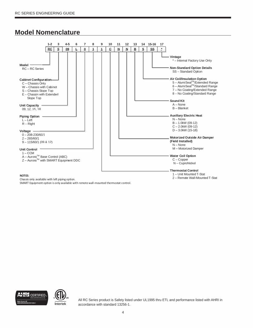
Model Nomenclature
RC SRC S 09 L 0 1 1 C4-5 6 7 8 9 10
Model RC – RC Series
Cabinet Configuration C – Chassis Only W – Chassis with Cabinet S – Chassis Slope Top E – Chassis with Extended Slope Top Unit Capacity 09, 12, 15, 18
Piping Option L – Left R – Right
Voltage 0 – 208-230/60/1 2 – 265/60/1 9 – 115/60/1 (09 & 12)
Unit Control 1 – CCM A – AuroraTM Base Control (ABC) Z – AuroraTM with SMART Equipment DDC
Vintage * – Internal Factory Use Only
Non-Standard Option Details SS – Standard Option
Air Coil/Insulation Option 5 – AlumiSealTM/Extended Range 6 – AlumiSealTM/Standard Range 7 – No Coating/Extended Range 8 – No Coating/Standard Range
Sound Kit A – None B – Blanket
Auxiliary Electric Heat N – None B – 1.0kW (09-12) C – 2.0kW (09-12) D – 3.0kW (15-18)
Motorized Outside Air Damper(Field Installed) N – None M – Motorized Damper
Water Coil Option C – Copper N – CuproNickel Thermostat Control 1 – Unit Mounted T-Stat 2 – Remote Wall-Mounted T-Stat
N11
NOTES: Chassis only available with left piping option.SMART Equipment option is only available with remote wall-mounted thermostat control.
31-2N B 5 SS
C Ser
Configassis Oassis assis Sassis wpe Top
acity15, 18
ption
ht
12 13 14 15-16*
17
60/1
(09 & 12)
ie
guOwSlwp
8
es
uOnwloit
s
urationnlyith Cabinetope Topth Extended
5
RC SERIES ENGINEERING GUIDE
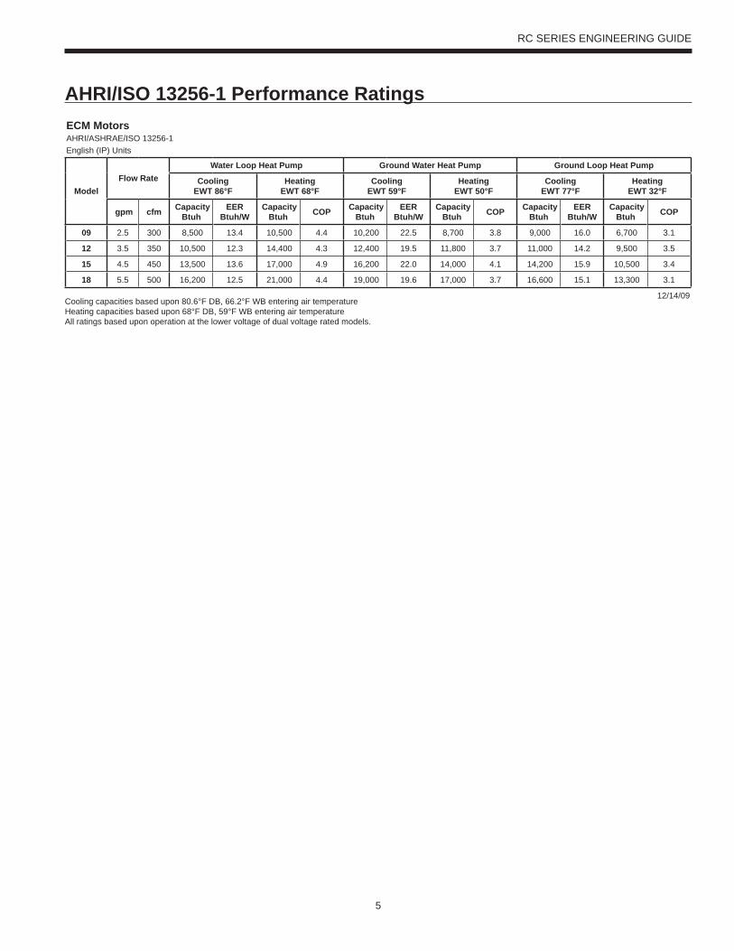
AHRI/ISO 13256-1 Performance RatingsECM MotorsAHRI/ASHRAE/ISO 13256-1English (IP) Units
ModelFlow Rate
Water Loop Heat Pump Ground Water Heat Pump Ground Loop Heat Pump
Cooling EWT 86°F
Heating EWT 68°F
CoolingEWT 59°F
HeatingEWT 50°F
Cooling EWT 77°F
HeatingEWT 32°F
gpm cfm Capacity Btuh
EER Btuh/W
Capacity Btuh COP Capacity
Btuh EER
Btuh/W Capacity
Btuh COP Capacity Btuh
EER Btuh/W
Capacity Btuh COP
09 2.5 300 8,500 13.4 10,500 4.4 10,200 22.5 8,700 3.8 9,000 16.0 6,700 3.1
12 3.5 350 10,500 12.3 14,400 4.3 12,400 19.5 11,800 3.7 11,000 14.2 9,500 3.5
15 4.5 450 13,500 13.6 17,000 4.9 16,200 22.0 14,000 4.1 14,200 15.9 10,500 3.4
18 5.5 500 16,200 12.5 21,000 4.4 19,000 19.6 17,000 3.7 16,600 15.1 13,300 3.1
12/14/09Cooling capacities based upon 80.6°F DB, 66.2°F WB entering air temperatureHeating capacities based upon 68°F DB, 59°F WB entering air temperatureAll ratings based upon operation at the lower voltage of dual voltage rated models.
6
RC SERIES ENGINEERING GUIDE
The performance standard AHRI/ASHRAE/ISO 13256-1 became effective January 1, 2000 and replaces ARI Standards 320, 325, and 330. This new standard has three major categories: Water Loop (comparable to ARI 320), Ground Water (ARI 325), and Ground Loop (ARI 330). Although these standards are similar there are some differences:Unit of Measure: The Cooling COP
The cooling efficiency is measured in EER (US version measured in Btuh per Watt. The Metric version is measured in a cooling COP (Watt per Watt) similar to the traditional COP measurement.
Water Conditions DifferencesEntering water temperatures have changed to reflect the centigrade temperature scale. For instance the water loop heating test is performed with 68°F (20°C) water rounded down from the old 70°F (21.1°C).
Air Conditions DifferencesEntering air temperatures have also changed (rounded down) to reflect the centigrade temperature scale. For instance the cooling tests are performed with 80.6°F (27°C) dry bulb and 66.2°F (19°C) wet bulb entering air instead of the traditional 80°F (26.7°C) DB and 67°F (19.4°C) WB entering air temperatures. 80.6/66.2 data may be converted to 80/67 using the entering air correction table. This represents a significantly lower relative humidity than the old 80/67 of 50% and will result in lower latent capacities.
Pump Power Correction CalculationWithin each model, only one water flow rate is specified for all three groups and pumping Watts are calculated using the following formula. This additional power is added onto the existing power consumption.• Pump power correction = (gpm x 0.0631) x (Press Drop x 2990) / 300Where ‘gpm’ is waterflow in gpm and ‘Press Drop’ is the pressure drop through the unit heat exchanger at rated water flow in feet of head.
Fan Power Correction CalculationFan power is corrected to zero external static pressure using the following equation. The nominal airflow is rated at a specific external static pressure. This effectively reduces the power consumption of the unit and increases cooling capacity but de-creases heating capacity. These Watts are significant enough in most cases to increase EER and COPs fairly dramatically over ARI 320, 325, and 330 ratings.• Fan Power Correction = (cfm x 0.472) x (esp x 249) / 300Where ‘cfm’ is airflow in cfm and ‘esp’ is the external static pressure at rated airflow in inches of water gauge.
ISO Capacity and Efficiency CalculationsThe following equations illustrate cooling calculations:• ISO Cooling Capacity = Cooling Capacity (Btuh) + (Fan Power Correction (Watts) x 3.412)• ISO EER Efficiency (W/W) = ISO Cooling Capacity (Btuh) x 3.412 / [Power Input (Watts) - Fan Power Correction (Watts) + Pump Power Correction (Watt)]The following equations illustrate heating calculations:• ISO Heating Capacity = Heating Capacity (Btuh) - (Fan Power Correction (Watts) x 3.412)• ISO COP Efficiency (W/W) = ISO Heating Capacity (Btuh) x 3.412 / [Power Input (Watts) - Fan Power Correction (Watts) + Pump Power Correction (Watt)]
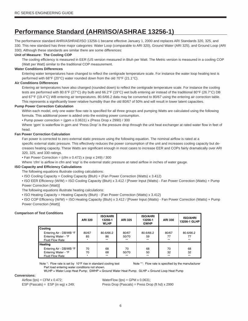
Comparison of Test Conditions
Conversions: Airflow (lps) = CFM x 0.472; WaterFlow (lps) = GPM x 0.0631; ESP (Pascals) = ESP (in wg) x 249; Press Drop (Pascals) = Press Drop (ft hd) x 2990
ARI 320ISO/AHRI 13256-1 WLHP
ARI 325ISO/AHRI 13256-1 GWHP
ARI 330 ISO/AHRI 13256-1 GLHP
CoolingEntering Air - DB/WB °F 80/67 80.6/66.2 80/67 80.6/66.2 80/67 80.6/66.2Entering Water - °F 85 86 50/70 59 77 77Fluid Flow Rate * ** ** ** ** **
HeatingEntering Air - DB/WB °F 70 68 70 68 70 68Entering Water - °F 70 68 50/70 50 32 32Fluid Flow Rate * ** ** ** ** **
Note *: Flow rate is set by 10°F rise in standard cooling test Note **: Flow rate is specified by the manufacturerPart load entering water conditions not shown.WLHP = Water Loop Heat Pump; GWHP = Ground Water Heat Pump; GLHP = Ground Loop Heat Pump
Performance Standard (AHRI/ISO/ASHRAE 13256-1)
7
RC SERIES ENGINEERING GUIDE
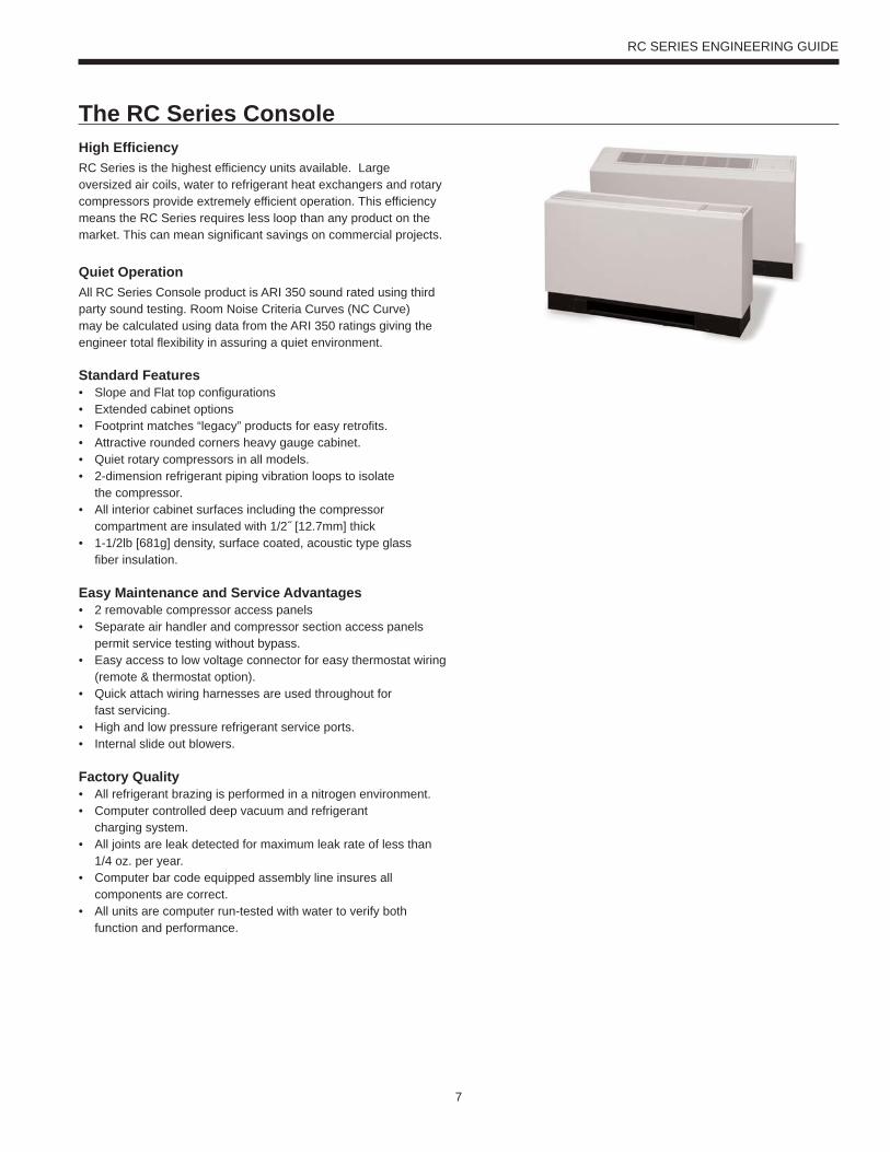
High EfficiencyRC Series is the highest efficiency units available. Large oversized air coils, water to refrigerant heat exchangers and rotary compressors provide extremely efficient operation. This efficiency means the RC Series requires less loop than any product on the market. This can mean significant savings on commercial projects.
Quiet OperationAll RC Series Console product is ARI 350 sound rated using third party sound testing. Room Noise Criteria Curves (NC Curve) may be calculated using data from the ARI 350 ratings giving the engineer total flexibility in assuring a quiet environment.
Standard Features• Slope and Flat top configurations• Extended cabinet options• Footprint matches “legacy” products for easy retrofits.• Attractive rounded corners heavy gauge cabinet.• Quiet rotary compressors in all models.• 2-dimension refrigerant piping vibration loops to isolate the compressor.• All interior cabinet surfaces including the compressor compartment are insulated with 1/2˝ [12.7mm] thick• 1-1/2lb [681g] density, surface coated, acoustic type glass fiber insulation.
Easy Maintenance and Service Advantages• 2 removable compressor access panels• Separate air handler and compressor section access panels permit service testing without bypass.• Easy access to low voltage connector for easy thermostat wiring (remote & thermostat option).• Quick attach wiring harnesses are used throughout for fast servicing.• High and low pressure refrigerant service ports.• Internal slide out blowers.
Factory Quality• All refrigerant brazing is performed in a nitrogen environment. • Computer controlled deep vacuum and refrigerant charging system.• All joints are leak detected for maximum leak rate of less than 1/4 oz. per year.• Computer bar code equipped assembly line insures all components are correct.• All units are computer run-tested with water to verify both function and performance.
The RC Series Console
8
RC SERIES ENGINEERING GUIDE
RefrigerantRC Series products all feature zero ozone depletion and low global warming potential refrigerant R-410A.
CabinetAll units are all constructed of corrosion resistant galvanized sheet metal with white polyester powder coat paint rated for more than 1000 hours of salt spray. Refrigerant circuit is designed to allow primary serviceability from the front. One access panel allows servicing of the fan motor, blower, and drain pan. Cabinet is designed to match "industry" foot print for ease of replacement.
Drain PanAll condensate connections are welded stainless steel tubes for economical corrosion free connections. Bacteria resistant stainless steel drain pan is designed to promote complete drainage and will never rust or corrode. Complete drainage helps to inhibit bacterial or microbial growth. Units feature an internally trapped condensate line.
CompressorsHigh efficiency R410A rotary compressors are used on every model. Rotary compressors (available in 208-230V & 265V 60Hz Single Phase) provide both the highest efficiency available and great reliability.
Electrical BoxUnit controls feature quick connect wiring harnesses for easy servicing. Large 75VA transformer assures adequate controls power for accessories.
Thermostatic Expansion ValveAll RC Series models utilize a balanced port bi-directional thermostatic expansion valve (TXV) for refrigerant metering. This allows precise refrigerant flow in a wide range of entering water variation (20 to 120°F [-7 to 49 °C]) found in geothermal systems.
Water to Refrigerant Coaxial Heat Exchanger CoilLarge oversized coaxial refrigerant to water heat exchangers provide unparalleled efficiency. The coaxes are designed for low pressure drop and low flow rates. All coaxes are pressure rated to 450 psi water side and 600 psi on the refrigerant side. Optional ThermaShield coated water-to-refrigerant coaxial heat exchanger is available to prevent condensation in low temperature loop operation.
Service Connections and ServiceabilityTwo Schrader service ports are provided in every unit. The suction side and discharge side ports are for field charging and servicing access. All valves are 7/16˝ SAE connections. All water and electrical connections are made from the front of the unit. Unit is designed for front access serviceability.
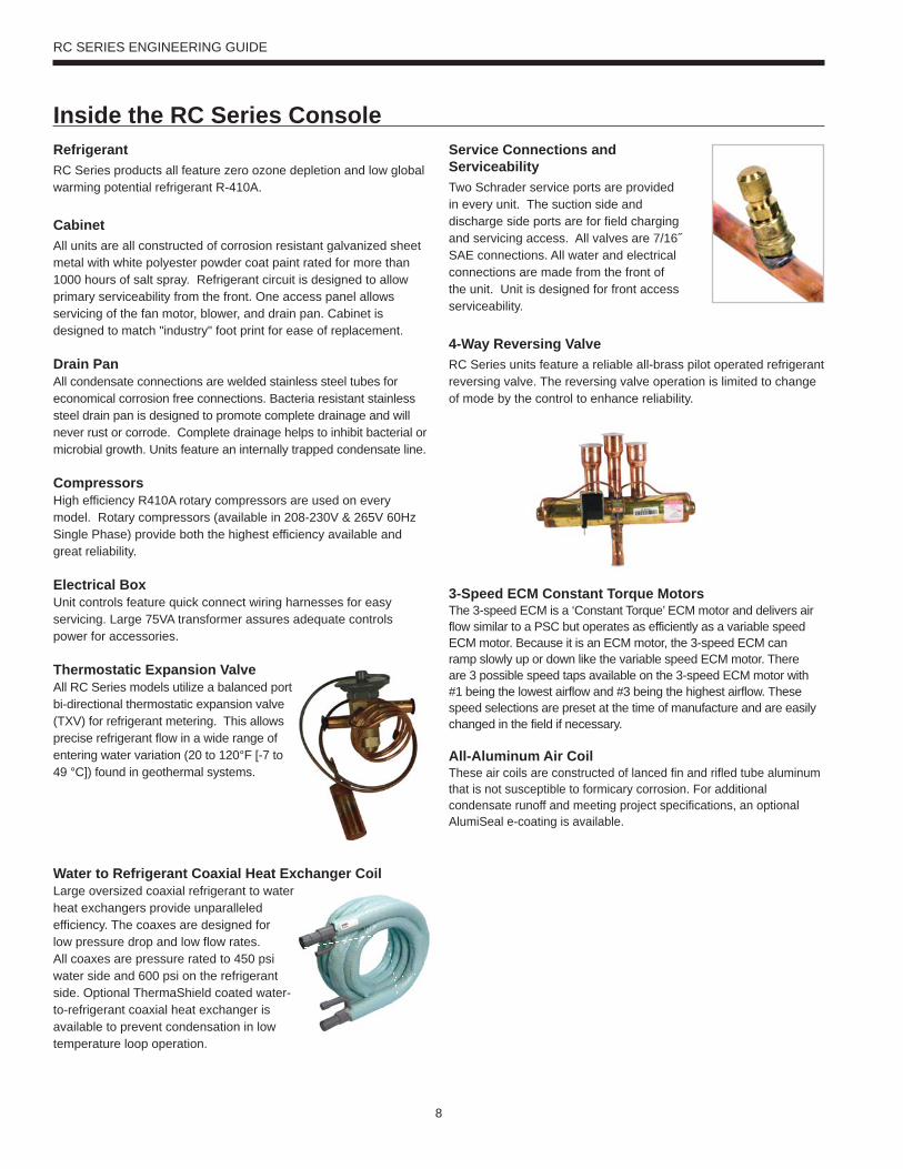
4-Way Reversing ValveRC Series units feature a reliable all-brass pilot operated refrigerant reversing valve. The reversing valve operation is limited to change of mode by the control to enhance reliability.
3-Speed ECM Constant Torque MotorsThe 3-speed ECM is a ‘Constant Torque’ ECM motor and delivers air flow similar to a PSC but operates as efficiently as a variable speed ECM motor. Because it is an ECM motor, the 3-speed ECM can ramp slowly up or down like the variable speed ECM motor. There are 3 possible speed taps available on the 3-speed ECM motor with #1 being the lowest airflow and #3 being the highest airflow. These speed selections are preset at the time of manufacture and are easily changed in the field if necessary.
All-Aluminum Air CoilThese air coils are constructed of lanced fin and rifled tube aluminum that is not susceptible to formicary corrosion. For additional condensate runoff and meeting project specifications, an optional AlumiSeal e-coating is available.
Inside the RC Series Console
9
RC SERIES ENGINEERING GUIDE
Control General Description Application Display/Interface Protocol Thermostat Options
CCM Control The CCM (Compressor control module) is a more reliable replacement for electro-mechanical control applications. It features a small microprocessor board that handles the lockout function of the unit. A second microporcessor handles the unit mounted thermostat for maintaining accurate room temperature.
Residential and commercial applications requiring minimal but reliable controls. Includes Random Start, High and low pressure switches and auto changeover capability.
Dial thermostat with Hi and Low fan speeds, and auto changeover or cont fan selection switches.
None Unit Mounted Digital Dial Thermostat
Remote Mounted Standard Thermostat
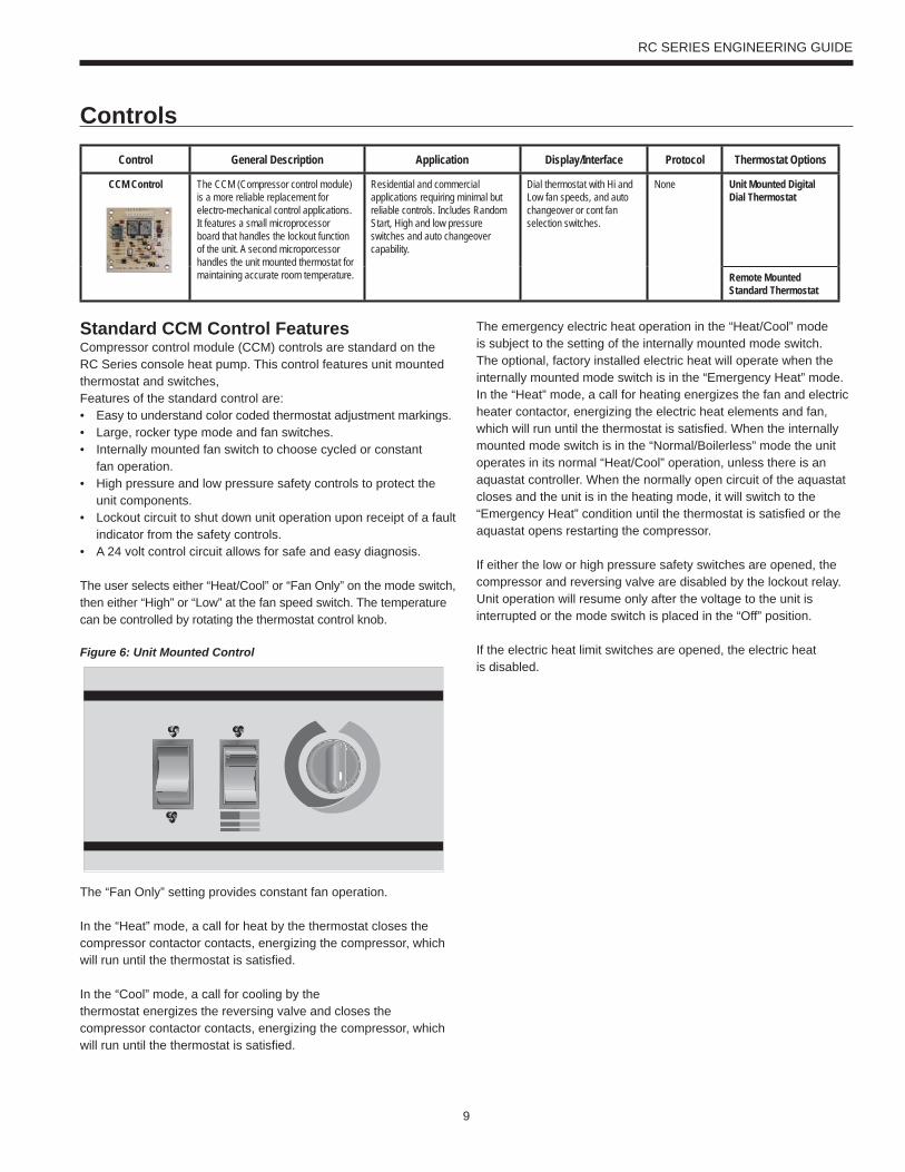
Standard CCM Control FeaturesCompressor control module (CCM) controls are standard on the RC Series console heat pump. This control features unit mounted thermostat and switches,Features of the standard control are:• Easy to understand color coded thermostat adjustment markings.• Large, rocker type mode and fan switches.• Internally mounted fan switch to choose cycled or constant fan operation.• High pressure and low pressure safety controls to protect the unit components.• Lockout circuit to shut down unit operation upon receipt of a fault indicator from the safety controls.• A 24 volt control circuit allows for safe and easy diagnosis.
The user selects either “Heat/Cool” or “Fan Only” on the mode switch, then either “High” or “Low” at the fan speed switch. The temperature can be controlled by rotating the thermostat control knob.
The “Fan Only” setting provides constant fan operation.
In the “Heat” mode, a call for heat by the thermostat closes the compressor contactor contacts, energizing the compressor, which will run until the thermostat is satisfied.
In the “Cool” mode, a call for cooling by the thermostat energizes the reversing valve and closes the compressor contactor contacts, energizing the compressor, which will run until the thermostat is satisfied.
The emergency electric heat operation in the “Heat/Cool” mode is subject to the setting of the internally mounted mode switch. The optional, factory installed electric heat will operate when the internally mounted mode switch is in the “Emergency Heat” mode. In the “Heat” mode, a call for heating energizes the fan and electric heater contactor, energizing the electric heat elements and fan, which will run until the thermostat is satisfied. When the internally mounted mode switch is in the “Normal/Boilerless” mode the unit operates in its normal “Heat/Cool” operation, unless there is an aquastat controller. When the normally open circuit of the aquastat closes and the unit is in the heating mode, it will switch to the “Emergency Heat” condition until the thermostat is satisfied or the aquastat opens restarting the compressor.
If either the low or high pressure safety switches are opened, the compressor and reversing valve are disabled by the lockout relay. Unit operation will resume only after the voltage to the unit is interrupted or the mode switch is placed in the “Off” position.
If the electric heat limit switches are opened, the electric heatis disabled.
Controls
Figure 6: Unit Mounted Control
10
RC SERIES ENGINEERING GUIDE
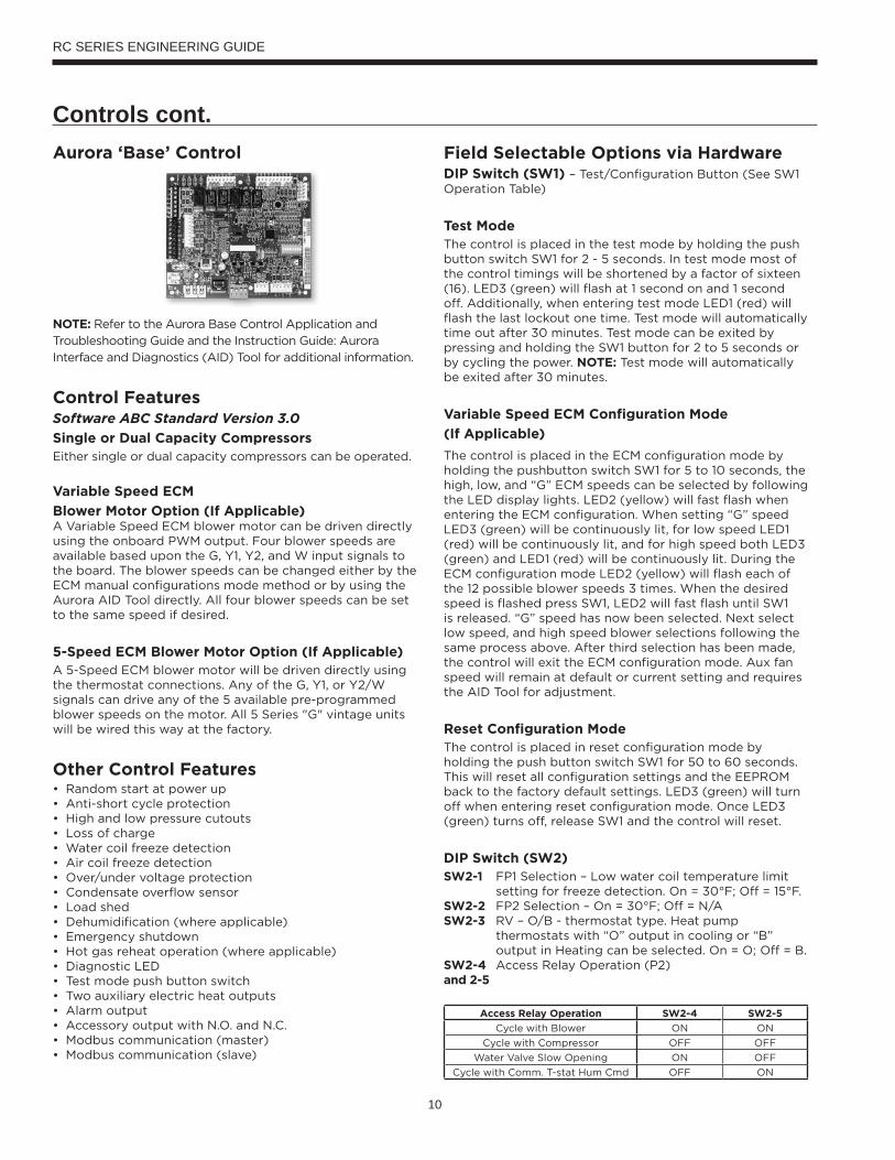
Controls cont.Aurora ‘Base’ Control
NOTE: Refer to the Aurora Base Control Application and
Troubleshooting Guide and the Instruction Guide: Aurora
Interface and Diagnostics (AID) Tool for additional information.
Control FeaturesSoftware ABC Standard Version 3.0
Single or Dual Capacity CompressorsEither single or dual capacity compressors can be operated.
Variable Speed ECM
Blower Motor Option (If Applicable)A Variable Speed ECM blower motor can be driven directly using the onboard PWM output. Four blower speeds are available based upon the G, Y1, Y2, and W input signals to the board. The blower speeds can be changed either by the ECM manual configurations mode method or by using the Aurora AID Tool directly. All four blower speeds can be set to the same speed if desired.
5-Speed ECM Blower Motor Option (If Applicable)A 5-Speed ECM blower motor will be driven directly using the thermostat connections. Any of the G, Y1, or Y2/W signals can drive any of the 5 available pre-programmed blower speeds on the motor. All 5 Series "G" vintage units will be wired this way at the factory.
Other Control Features• Random start at power up• Anti-short cycle protection• High and low pressure cutouts• Loss of charge• Water coil freeze detection• Air coil freeze detection• Over/under voltage protection• Condensate overflow sensor• Load shed• Dehumidification (where applicable)• Emergency shutdown• Hot gas reheat operation (where applicable)• Diagnostic LED• Test mode push button switch• Two auxiliary electric heat outputs• Alarm output• Accessory output with N.O. and N.C.• Modbus communication (master)• Modbus communication (slave)
Field Selectable Options via HardwareDIP Switch (SW1) – Test/Configuration Button (See SW1 Operation Table)
Test ModeThe control is placed in the test mode by holding the push button switch SW1 for 2 - 5 seconds. In test mode most of the control timings will be shortened by a factor of sixteen (16). LED3 (green) will flash at 1 second on and 1 second off. Additionally, when entering test mode LED1 (red) will flash the last lockout one time. Test mode will automatically time out after 30 minutes. Test mode can be exited by pressing and holding the SW1 button for 2 to 5 seconds or by cycling the power. NOTE: Test mode will automatically be exited after 30 minutes.
Variable Speed ECM Configuration Mode
(If Applicable)
The control is placed in the ECM configuration mode by holding the pushbutton switch SW1 for 5 to 10 seconds, the high, low, and “G” ECM speeds can be selected by following the LED display lights. LED2 (yellow) will fast flash when entering the ECM configuration. When setting “G” speed LED3 (green) will be continuously lit, for low speed LED1 (red) will be continuously lit, and for high speed both LED3 (green) and LED1 (red) will be continuously lit. During the ECM configuration mode LED2 (yellow) will flash each of the 12 possible blower speeds 3 times. When the desired speed is flashed press SW1, LED2 will fast flash until SW1 is released. “G” speed has now been selected. Next select low speed, and high speed blower selections following the same process above. After third selection has been made, the control will exit the ECM configuration mode. Aux fan speed will remain at default or current setting and requires the AID Tool for adjustment.
Reset Configuration ModeThe control is placed in reset configuration mode by holding the push button switch SW1 for 50 to 60 seconds. This will reset all configuration settings and the EEPROM back to the factory default settings. LED3 (green) will turn off when entering reset configuration mode. Once LED3 (green) turns off, release SW1 and the control will reset.
DIP Switch (SW2) SW2-1 FP1 Selection – Low water coil temperature limit
setting for freeze detection. On = 30°F; Off = 15°F.SW2-2 FP2 Selection – On = 30°F; Off = N/ASW2-3 RV – O/B - thermostat type. Heat pump
thermostats with “O” output in cooling or “B” output in Heating can be selected. On = O; Off = B.
SW2-4 Access Relay Operation (P2)and 2-5
Access Relay Operation SW2-4 SW2-5
Cycle with Blower ON ON
Cycle with Compressor OFF OFF
Water Valve Slow Opening ON OFF
Cycle with Comm. T-stat Hum Cmd OFF ON
11
RC SERIES ENGINEERING GUIDE
Controls - cont.Cycle with Blower - The accessory relay will cycle with the blower output.
Cycle with Compressor - The accessory relay will cycle with the compressor output.
Water Valve Slow Opening - The accessory relay will cycle and delay both the blower and compressor output for 90 seconds.
SW2-6 CC Operation – selection of single or dual capacity compressor. On = Single Stage; Off = Dual Capacity
SW2-7 Lockout and Alarm Outputs (P2) – selection of a continuous or pulsed output for both the LO and ALM Outputs. On = Continuous; Off = Pulsed
SW2-8 Future Use
Alarm Jumper Clip SelectionFrom the factory, ALM is connected to 24 VAC via JW2. By cutting JW2, ALM becomes a dry contact connected to ALG.
Variable Speed ECM Blower SpeedsThe blower speeds can be changed either by using the ECM manual configurations mode method or by using the Aurora AID Tool directly (see Instruction Guide: Aurora Interface and Diagnostics (AID) Tool topic).
Field Selectable Options via Software(Selectable via the Aurora AID Tool)ECM Blower SpeedsAn ECM blower motor can be driven directly using the onboard PWM output. Four blower speeds are available, based upon the “G”, Y1 (low), Y2 (high), and Aux input signals to the board. The blower speeds can be changed either by the ECM manual configurations mode method (see ECM Configuration Mode topic) or by using the Aurora AID Tool directly. All four blower speeds can be set to the same speed if desired. Aux blower speed will remain at default or current setting and requires the AID Tool for adjustment.
Safety FeaturesThe following safety features are provided to protect the compressor, heat exchangers, wiring and other components from damage caused by operation outside of design conditions.
Fuse – a 3 amp automotive type plug-in fuse provides protection against short circuit or overload conditions.
Anti-Short Cycle Protection – 4 minute anti-short cycle protection for the compressor.
Random Start – 5 to 80 second random start upon power up.
Fault Retry – in the fault condition, the control will stage off the outputs and then “try again” to satisfy the thermostat Y input call. Once the thermostat input calls are satisfied, the control will continue on as if no fault occurred. If 3 consecutive faults occur without satisfying the thermostat Y input call, then the control will go to Lockout mode.
Lockout – when locked out, the blower will operate continuously in “G” speed, and PSC blower motor output will remain on. The Alarm output (ALM) and Lockout output (L) will be turned on. The fault type identification display LED1 (Red) shall flash the fault code. To reset lockout conditions with SW2-8 On, thermostat inputs “Y1”, “Y2”, and “W” must be removed for at least 3 seconds. To reset lockout conditions with SW2-8 Off, thermostat inputs “Y1”, “Y2”, “W”, and “DH” must be removed for at least 3 seconds. Lockout may also be reset by turning power off for at least 30 seconds or by enabling the emergency shutdown input for at least 3 seconds.
Lockout With Emergency Heat - if the control is locked out in the heating mode, and a Y2 or W input is received, the control will operate in the emergency heat mode while the compressor is locked out. The first emergency heat output will be energized 10 seconds after the W input is received, and the blower will shift to high speed. If the control remains locked out, and the W input is present, additional stage of emergency heat will stage on after 2 minutes. When the W input is removed, all of the emergency heat outputs will turn off, and the ECM blower will shift to “G” speed and PSC blower motor output will remain on.
High Pressure – fault is recognized when the Normally Closed High Pressure Switch, P4-9/10 opens, no matter how momentarily. The High Pressure Switch is electrically in series with the Compressor Contactor and serves as a hard-wired limit switch if an overpressure condition should occur.
Low Pressure - fault is recognized when the Normally Closed Low Pressure Switch, P4-7/8 is continuously open for 30 seconds. Closure of the LPS any time during the 30 second recognition time restarts the 30 second continuous open requirement. A continuously open LPS shall not be recognized during the 2 minute startup bypass time.
Loss of Charge – fault is recognized when the Normally Closed Low Pressure Switch, P4-7/8 is open prior to the compressor starting.
Condensate Overflow - fault is recognized when the impedance between this line and 24 VAC common or chassis ground drops below 100K ohms for 30 seconds continuously.
Freeze Detection (Coax) - set points shall be either 30°F or 15°F. When the thermistor temperature drops below the selected set point, the control shall begin counting down the 30 seconds delay. If the thermistor value rises above the selected set point, then the count should reset. The resistance value must remain below the selected set point for the entire length of the appropriate delay to be recognized as a fault. This fault will be ignored for the initial 2 minutes of the compressor run time.
Freeze Detection (Air Coil) - uses the FP2 input to protect against ice formation on the air coil. The FP2 input will operate exactly like FP1 except that the set point is 30 degrees and is not field adjustable.
12
RC SERIES ENGINEERING GUIDE
Controls - cont.Over/Under Voltage Shutdown - An over/under voltage condition exists when the control voltage is outside the range of 18 VAC to 30 VAC. If the over/under voltage shutdown lasts for 15 minutes, the lockout and alarm relay will be energized. Over/under voltage shutdown is self-resetting in that if the voltage comes back within range of 18 VAC to 30 VAC for at least 0.5 seconds, then normal operation is restored.
Operation DescriptionPower Up - The unit will not operate until all the inputs and safety controls are checked for normal conditions. The unit has a 5 to 80 second random start delay at power up. Then the compressor has a 4 minute anti-short cycle delay after the random start delay.
Standby In standby mode, Y1, Y2, W, DH, and G are not active. Input O may be active. The blower and compressor will be off.
Heating OperationSingle Compressor Heating, 2nd Stage (Y1, Y2) The compressor will be staged to full capacity 20 seconds after Y2 input is received. The ECM blower will shift to high speed seconds after the Y2 input is received.
Dual Compressor Heating, 2nd Stage (Y1, Y2) In dual compressor operation, two ABC boards used in 24 VAC operation, there will be a Y2 call to the Y1 input on the second ABC. The compressor will stage to full capacity 30 seconds after Y1 input is received to the second board.
Single Compressor Heating, 3rd Stage (Y1, Y2, W) The hot water pump is de-energized and the first stage of electric heat is energized 10 seconds after the W command is received. If the demand continues the second stage of electric heat will be energized after 5 minutes.
Dual Compressor Heating, 3rd Stage (Y1, Y2, W) - The first stage of electric heat is energized 10 seconds after the W command is received. If the demand continues the second stage of electric heat will be energized after 5 minutes
Emergency Heat (W) - The blower will be started on “G” speed, 10 seconds later the first stage of electric heat will be turned on. 5 seconds after the first stage of electric heat is energized the blower will shift to Aux speed. If the emergency heat demand is not satisfied after 2 minutes the second electric heat stage will be energized.
Blower (G) - The blower will start immediately upon receiving a thermostat G command. If there are no other commands from the thermostat the ECM will run on “G” speed until the G command is removed. Regardless of blower input (G) from the thermostat, the blower will remain on for 30 seconds at the end of each heating cycle.
Cooling OperationIn all cooling operations, the reversing valve directly tracks the O input. Thus, anytime the O input is present, the reversing valve will be energized.
Single Compressor Cooling, 2nd Stage (Y1, Y2, 0) The compressor will be staged to full capacity 20 seconds after Y2 input was received. The ECM blower will shift to high speed 15 seconds after the Y2 input was received.
Dual Compressor Cooling, 2nd Stage (Y1, Y2, O) In dual compressor operation, two ABC boards used in 24 VAC operation, there will be a Y2 call to the Y1 input on the second ABC. The compressor will stage to full capacity 30 seconds after Y1 input is received to the second board.
Blower (G) - The blower will start immediately upon receiving a thermostat G command. If there are no other commands from the thermostat the ECM will run on “G” speed until the G command is removed. Regardless of blower input (G) from the thermostat, the blower will remain on for 30 seconds at the end of each heating, cooling, and emergency heat cycle.
Dehumidification (Y1, O, DH or Y1, Y2, O, DH) - When a DH command is received from the thermostat during a compressor call for cooling the ECM blower speed will be reduced by 15% to increase dehumidification.
Emergency Shutdown - Four (4) seconds after a valid ES input, P2-7 is present, all control outputs will be turned off and remain off until the emergency shutdown input is no longer present. The first time that the compressor is started after the control exits the emergency shutdown mode, there will be an anti-short cycle delay followed by a random start delay. Input must be tied to common to activate.
Continuous Blower Operation - The blower output will be energized any time the control has a G input present, unless the control has an emergency shutdown input present. The blower output will be turned off when G input is removed.
Load Shed - The LS input disables all outputs with the exception of the blower output. When the LS input has been cleared, the anti-short cycle timer and random start timer will be initiated. Input must be tied to common to activate.
13
RC SERIES ENGINEERING GUIDE
Controls - cont.
CC2
EH1
Fact
ory
Faul t
ALG
ALMLSES ACC
cStatus
AURORA BASE CONTROL™
RV – K1
CC2
CC – K2
CC Hi – K3
Fan – K4
Alarm – K5
Acc – K6
ACC
no
ACC
nc
O/BCRLO G Y1 Y2 W DH
3A-Fu
se
O/BCRLO G Y1 Y2 W DH
LOG
HICCGCCFGFR
HPHPLP
FP2FP2FP1
REVREV
CFM
PWM
ECM PWM
Fact
ory
Factory Fan Connection
R RC
CC
RS 48
5
EH2C
EH1C
CO
(+)(-)RCRS
485 E
xpFa
ctory
Com1
Com2
Config
G
G
G
YR
SW1 Test
FP1 – 15oF/30oF
JW2 - Alarm
P11
P5
P2 P1
P8
P7
P9
P6
P3
SW2
P13P4 FP2 – 15oF/30oF
RV – B/OACC – Dip 4
ACC – Dip 5CC – Dual/Single
L – Pulse/ContinuousReheat/Normal
Fact
ory U
se
Field ConnectionsField Connections
C
LP
FP1
F
CC
G
Y1
1
2
3
4
5
6
7
8
Off On
N/A
RS48
5 NET
LED3
LED2LED1
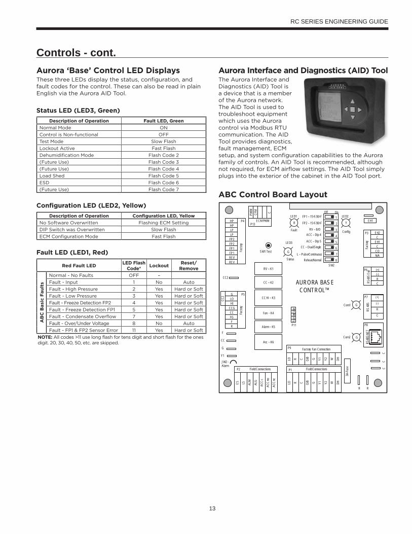
Aurora Interface and Diagnostics (AID) ToolThe Aurora Interface and Diagnostics (AID) Tool is a device that is a member of the Aurora network. The AID Tool is used to troubleshoot equipment which uses the Aurora control via Modbus RTU communication. The AID Tool provides diagnostics, fault management, ECM setup, and system configuration capabilities to the Aurora family of controls. An AID Tool is recommended, although not required, for ECM airflow settings. The AID Tool simply plugs into the exterior of the cabinet in the AID Tool port.
ABC Control Board Layout
Aurora ‘Base’ Control LED DisplaysThese three LEDs display the status, configuration, and fault codes for the control. These can also be read in plain English via the Aurora AID Tool.
Status LED (LED3, Green)
Description of Operation Fault LED, Green
Normal Mode ON
Control is Non-functional OFF
Test Mode Slow Flash
Lockout Active Fast Flash
Dehumidification Mode Flash Code 2
(Future Use) Flash Code 3
(Future Use) Flash Code 4
Load Shed Flash Code 5
ESD Flash Code 6
(Future Use) Flash Code 7
Configuration LED (LED2, Yellow)
Description of Operation Configuration LED, Yellow
No Software Overwritten Flashing ECM Setting
DIP Switch was Overwritten Slow Flash
ECM Configuration Mode Fast Flash
Fault LED (LED1, Red)
Red Fault LEDLED Flash
Code*Lockout
Reset/Remove
AB
C B
asi
c F
au
lts
Normal - No Faults OFF –
Fault - Input 1 No Auto
Fault - High Pressure 2 Yes Hard or Soft
Fault - Low Pressure 3 Yes Hard or Soft
Fault - Freeze Detection FP2 4 Yes Hard or Soft
Fault - Freeze Detection FP1 5 Yes Hard or Soft
Fault - Condensate Overflow 7 Yes Hard or Soft
Fault - Over/Under Voltage 8 No Auto
Fault - FP1 & FP2 Sensor Error 11 Yes Hard or Soft
NOTE: All codes >11 use long flash for tens digit and short flash for the ones digit. 20, 30, 40, 50, etc. are skipped.
14
RC SERIES ENGINEERING GUIDE
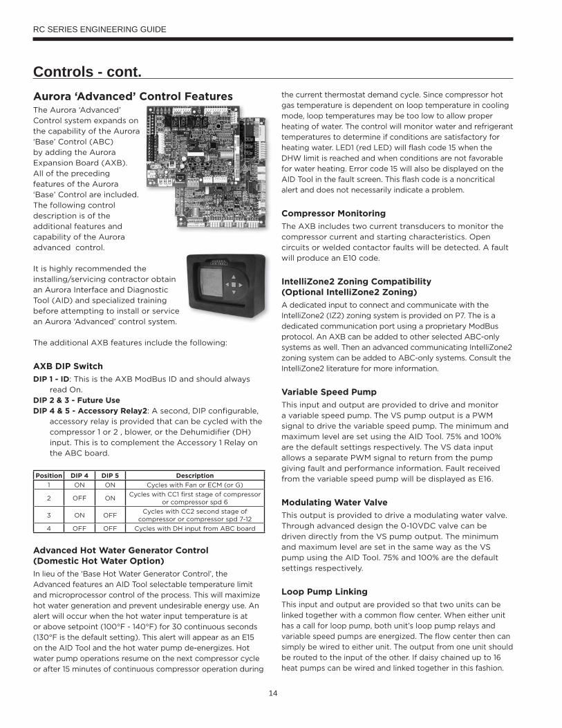
Controls - cont.Aurora ‘Advanced’ Control FeaturesThe Aurora ‘Advanced’
Control system expands on
the capability of the Aurora
‘Base’ Control (ABC)
by adding the Aurora
Expansion Board (AXB).
All of the preceding
features of the Aurora
‘Base’ Control are included.
The following control
description is of the
additional features and
capability of the Aurora
advanced control.
It is highly recommended the
installing/servicing contractor obtain
an Aurora Interface and Diagnostic
Tool (AID) and specialized training
before attempting to install or service
an Aurora ‘Advanced’ control system.
The additional AXB features include the following:
AXB DIP Switch
DIP 1 - ID: This is the AXB ModBus ID and should always
read On.
DIP 2 & 3 - Future UseDIP 4 & 5 - Accessory Relay2: A second, DIP configurable,
accessory relay is provided that can be cycled with the
compressor 1 or 2 , blower, or the Dehumidifier (DH)
input. This is to complement the Accessory 1 Relay on
the ABC board.
Position DIP 4 DIP 5 Description
1 ON ON Cycles with Fan or ECM (or G)
2 OFF ONCycles with CC1 first stage of compressor
or compressor spd 6
3 ON OFFCycles with CC2 second stage of
compressor or compressor spd 7-12
4 OFF OFF Cycles with DH input from ABC board
Advanced Hot Water Generator Control (Domestic Hot Water Option)
In lieu of the ‘Base Hot Water Generator Control’, the
Advanced features an AID Tool selectable temperature limit
and microprocessor control of the process. This will maximize
hot water generation and prevent undesirable energy use. An
alert will occur when the hot water input temperature is at
or above setpoint (100°F - 140°F) for 30 continuous seconds
(130°F is the default setting). This alert will appear as an E15
on the AID Tool and the hot water pump de-energizes. Hot
water pump operations resume on the next compressor cycle
or after 15 minutes of continuous compressor operation during
the current thermostat demand cycle. Since compressor hot
gas temperature is dependent on loop temperature in cooling
mode, loop temperatures may be too low to allow proper
heating of water. The control will monitor water and refrigerant
temperatures to determine if conditions are satisfactory for
heating water. LED1 (red LED) will flash code 15 when the
DHW limit is reached and when conditions are not favorable
for water heating. Error code 15 will also be displayed on the
AID Tool in the fault screen. This flash code is a noncritical
alert and does not necessarily indicate a problem.
Compressor Monitoring
The AXB includes two current transducers to monitor the
compressor current and starting characteristics. Open
circuits or welded contactor faults will be detected. A fault
will produce an E10 code.
IntelliZone2 Zoning Compatibility (Optional IntelliZone2 Zoning)
A dedicated input to connect and communicate with the
IntelliZone2 (IZ2) zoning system is provided on P7. The is a
dedicated communication port using a proprietary ModBus
protocol. An AXB can be added to other selected ABC-only
systems as well. Then an advanced communicating IntelliZone2
zoning system can be added to ABC-only systems. Consult the
IntelliZone2 literature for more information.
Variable Speed Pump
This input and output are provided to drive and monitor
a variable speed pump. The VS pump output is a PWM
signal to drive the variable speed pump. The minimum and
maximum level are set using the AID Tool. 75% and 100%
are the default settings respectively. The VS data input
allows a separate PWM signal to return from the pump
giving fault and performance information. Fault received
from the variable speed pump will be displayed as E16.
Modulating Water Valve
This output is provided to drive a modulating water valve.
Through advanced design the 0-10VDC valve can be
driven directly from the VS pump output. The minimum
and maximum level are set in the same way as the VS
pump using the AID Tool. 75% and 100% are the default
settings respectively.
Loop Pump Linking
This input and output are provided so that two units can be
linked together with a common flow center. When either unit
has a call for loop pump, both unit’s loop pump relays and
variable speed pumps are energized. The flow center then can
simply be wired to either unit. The output from one unit should
be routed to the input of the other. If daisy chained up to 16
heat pumps can be wired and linked together in this fashion.
15
RC SERIES ENGINEERING GUIDE
Controls - cont.Advanced Communication Ports
Communication ports P6 and P8 will provide future
expansion via dedicated protocols. These are for future use.
Smart Grid-On Peak (SG) Input
The 'On Peak' input was designed to allow utilities to
utilize simple radio controlled switches to control the On
Electric Peak behavior of the 5 and 7 Series Geothermal
Heat Pumps. With a closed contact signal, this input will
limit the operation and thus the power consumption of the
unit by one of the below selections. The AID Tool will allow
configuration of this input for the action of:
• No Action
• Disable compressor operation until removed
• Go to On Peak thermostat settings until removed
[Requires Com T-Stat] (Future Release)
• Compressor limited to 50% or low cap until removed
[dual capacity or variable speed only] (Future Release)
• Disable compressor operation for 1/2 hr (can be
removed immediately) (Future Release)
Then Flash Code 7 on the Green LED for the 'On Peak' mode.
And On Peak will display on communicating thermostats.
Home Automation 1 and 2 Inputs
The Home automation inputs are simple closed contact
inputs that will trigger an AID Tool and thermostat alert
for the homeowner. These would require optional sensors
and or equipment for connection to the AXB board. With
two inputs two different sensors can be selected. The
selected text will then be displayed on the AID Tool and
communicating thermostats. These events will NOT alter
functionality or operation of the heat pump/accessories
and is for homeowner/service notification only.
Home Automation 1 - E23 HA1With a closed dry contact signal, this input will cause an
alarm and Alert Code 23 to indicate on the stat or flash
on ABC. The AID Tool will allow configuration of this input
between the following selections:
• No Action
• Home Automation Fault [no lockout info only]
- Output from home automation system
• Security Alarm [no lockout info only]
- Output from home security
• Sump Alarm Fault [no lockout info only]
- Switch output from sump sensor
• Smoke/CO Alarm Fault [no lockout info only]
- Switch output from Smoke/CO sensor
• Dirty Filter Alarm [no lockout info only]
- Output from dirty filter sensor
Home Automation 2 – E24 HA2With a closed dry contact signal, this input will cause an
alarm and Alert Code 24 to indicate on the stat or flash
on ABC. The AID Tool will allow configuration of this input
between the following selections:
• No Action
• Home Automation Fault [no lockout info only]
- Output from home automation system
• Security Alarm [no lockout info only]
- Output from home security
• Sump Alarm Fault [no lockout info only]
- Switch output from sump sensor
• Smoke/CO Alarm Fault [no lockout info only]
- Switch output from Smoke/CO sensor
• Dirty Filter Alarm [no lockout info only]
- Output from dirty filter sensor
Monitoring Sensor KitsEnergy Monitoring (Standard Sensor Kit on ‘Advanced’ models)
The Energy Monitoring Kit includes two current transducers
(blower and electric heat) added to the existing two
compressor sensors so that the complete power usage of
the heat pump can be measured. The AID Tool provides
configuration detail for the type of blower motor and a
line voltage calibration procedure to improve the accuracy.
This information can be displayed on the AID Tool or
selected communicating thermostats. The TPCM32U03/04
will display instantaneous energy use while the color
touchscreen TPCC32U01 will in addition display a 13 month
history in graph form.
Refrigerant Monitoring (optional sensor kit)
The optional Refrigerant Monitoring Kit includes two
pressure transducers, and three temperature sensors,
heating liquid line, suction temperature and existing cooling
liquid line (FP1). These sensors allow the measurement
of discharge and suction pressures, suction and liquid line
temperatures as well as superheat and subcooling. This
information will only be displayed on the AID Tool.
Performance Monitoring (optional sensor kit)
The optional Performance Monitoring Kit includes three
temperature sensors, entering and leaving water, leaving
air temperature and a water flow rate sensor. With this kit
heat of extraction and rejection will be calculated. This
requires configuration using the AID Tool for selection of
water or antifreeze.

16
RC SERIES ENGINEERING GUIDE
Aurora ‘Advanced’ Control LED DisplaysThese three LEDs display the status, configuration, and fault codes for the control. These can also be read in plain English via the Aurora AID Tool.
Status LED (LED3, Green)
Description of Operation Fault LED, Green
Normal Mode ON
Control is Non-functional OFF
Test Mode Slow Flash
Lockout Active Fast Flash
Dehumidification Mode Flash Code 2
Load Shed Flash Code 5
Emergency Shutdown Flash Code 6
On Peak Mode Flash Code 7
(Future Use) Flash Code 8
(Future Use) Flach Code 9
Configuration LED (LED2, Yellow)
Description of Operation Configuration LED, Yellow
No Software Overwritten ECM Setting
DIP Switch Overwritten Slow Flash
ECM Configuration Mode Fast Flash
Reset Configuration Mode OFF
Special Modes and Applications5-Speed ECM Blower Motor
Normally the 5-Speed ECM motor can be driven off
of thermostat signals and the ABC connector P9.
Communicating thermostats, however present a special
problem in this application since they operate without 24
VAC thermostat signals. The ABC board is wired to operate
these systems from the alternate relay output signals CC1,
CC2, Fan, and EH1 and should be wired for this.
Communicating Digital Thermostats
The Aurora controls system also features either mono-
chromatic or color touch screen graphic display
thermostats for user interface. These displays not only
feature easy to use graphical interface but display alerts
and faults in plain English. Many of the features discussed
here may not be applicable without these thermostats.
Dehumidification – Passive
In passive dehumidification mode, the airflow is reduced
by 15% from the heating airflow setting. If cooling airflow is
set to +5, -5 or -10% of heating airflow it will automatically
be set to -15% of heating airflow whenever the
dehumidification call is present in the communicating stat
or from the thermostat input DH. If the airflow for cooling is
already set to -15% no airflow change will be noticed from
normal cooling. Dehumidification mode will be shown on
the ABC and the communicating thermostats.
Fault LED (LED1, Red)
Red Fault LEDLED Flash
Code *Lockout
Reset/ Remove
Fault Condition Summary
AB
C B
asi
c F
au
lts
Normal - No Faults Off -
Fault-Input 1 No Auto Tstat input error. Autoreset upon condition removal.
Fault-High Pressure 2 Yes Hard or Soft HP switch has tripped (>600 psi)
Fault-Low Pressure 3 Yes Hard or Soft Low Pressure Switch has tripped (<40 psi for 30 continuous sec.)
Fault-Freeze Detection FP2 4 Yes Hard or Soft Freeze protection sensor has tripped (<15 or 30 degF for 30 continuous sec.)
Fault-Freeze Detection FP1 5 Yes Hard or Soft Freeze protection sensor has tripped (<15 or 30 degF for 30 continuous sec.)
Fault-Condensate Overflow 7 Yes Hard or Soft Condensate switch has shown continuity for 30 continuous sec.
Fault-Over/Under Voltage 8 No Auto Instantaneous voltage is out of range. **Controls shut down until resolved.
Fault-FP1 Snsr Error 11 Yes Hard or Soft If FP1 Sensor Error
AB
C &
AX
B A
dvan
ce
d F
au
lts
Fault-Compressor Monitor 10 Yes Hard or Soft Open Crkt, Run, Start or welded cont
Non-CriticAXBSnsrErr 13 No Auto Any Other Sensor Error
CriticAXBSnsrErr 14 Yes Hard or Soft Sensor Error for EEV or HW
Alert-HotWtr 15 No Auto HW over limit or logic lockout. HW pump deactivated.
Fault-VarSpdPump 16 No Auto Alert is read from PWM feedback.
Not Used 17 No Auto IZ2 Com Fault. Autoreset upon condition removal.
Non-CritComErr 18 No Auto Any non-critical com error
Fault-CritComErr 19 No Auto Any critical com error. Auto reset upon condition removal
Alarm - Low Loop Pressure 21 No Auto Loop pressure is below 3 psi for more than 3 minutes
Alarm - Home Automation 1 23 No Auto Closed contact input is present on Dig 2 input - Text is configurable
Alarm - Home Automation 2 24 No Auto Closed contact input is present on Dig 3 input - Text is configurable
NOTES: *All codes >11 use long flash for tens digit and short flash for the ones digit. 20, 30, 40, 50 etc. are skipped!Alert’ is a noncritical sensor or function that has failed. Normal operation of the heat pump is maintained but service is desired at some point.
Controls - cont.
17
RC SERIES ENGINEERING GUIDE
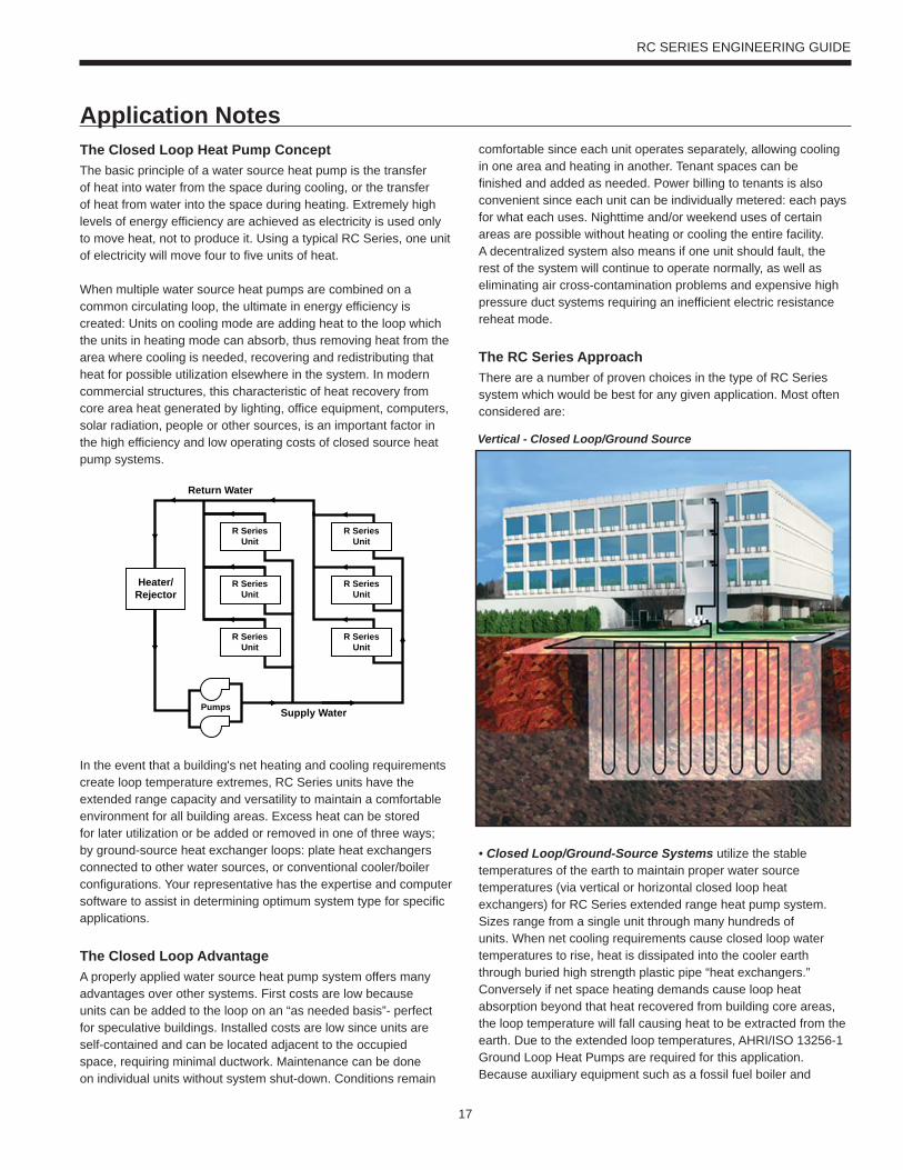
The Closed Loop Heat Pump ConceptThe basic principle of a water source heat pump is the transfer of heat into water from the space during cooling, or the transfer of heat from water into the space during heating. Extremely high levels of energy efficiency are achieved as electricity is used only to move heat, not to produce it. Using a typical RC Series, one unit of electricity will move four to five units of heat.
When multiple water source heat pumps are combined on a common circulating loop, the ultimate in energy efficiency is created: Units on cooling mode are adding heat to the loop which the units in heating mode can absorb, thus removing heat from the area where cooling is needed, recovering and redistributing that heat for possible utilization elsewhere in the system. In modern commercial structures, this characteristic of heat recovery from core area heat generated by lighting, office equipment, computers, solar radiation, people or other sources, is an important factor in the high efficiency and low operating costs of closed source heat pump systems.
In the event that a building's net heating and cooling requirements create loop temperature extremes, RC Series units have the extended range capacity and versatility to maintain a comfortable environment for all building areas. Excess heat can be stored for later utilization or be added or removed in one of three ways; by ground-source heat exchanger loops: plate heat exchangers connected to other water sources, or conventional cooler/boiler configurations. Your representative has the expertise and computer software to assist in determining optimum system type for specific applications.
The Closed Loop AdvantageA properly applied water source heat pump system offers many advantages over other systems. First costs are low because units can be added to the loop on an “as needed basis”- perfect for speculative buildings. Installed costs are low since units are self-contained and can be located adjacent to the occupied space, requiring minimal ductwork. Maintenance can be done on individual units without system shut-down. Conditions remain
comfortable since each unit operates separately, allowing cooling in one area and heating in another. Tenant spaces can be finished and added as needed. Power billing to tenants is also convenient since each unit can be individually metered: each pays for what each uses. Nighttime and/or weekend uses of certain areas are possible without heating or cooling the entire facility. A decentralized system also means if one unit should fault, the rest of the system will continue to operate normally, as well as eliminating air cross-contamination problems and expensive high pressure duct systems requiring an inefficient electric resistance reheat mode.
The RC Series ApproachThere are a number of proven choices in the type of RC Series system which would be best for any given application. Most often considered are:
• Closed Loop/Ground-Source Systems utilize the stable temperatures of the earth to maintain proper water source temperatures (via vertical or horizontal closed loop heat exchangers) for RC Series extended range heat pump system. Sizes range from a single unit through many hundreds of units. When net cooling requirements cause closed loop water temperatures to rise, heat is dissipated into the cooler earth through buried high strength plastic pipe “heat exchangers.” Conversely if net space heating demands cause loop heat absorption beyond that heat recovered from building core areas, the loop temperature will fall causing heat to be extracted from the earth. Due to the extended loop temperatures, AHRI/ISO 13256-1 Ground Loop Heat Pumps are required for this application.Because auxiliary equipment such as a fossil fuel boiler and
Supply Water
Return Water
Pumps
R SeriesUnit
R SeriesUnit
R SeriesUnit
R SeriesUnit
R SeriesUnit
R SeriesUnit
Heater/Rejector
Vertical - Closed Loop/Ground Source
Application Notes

18
RC SERIES ENGINEERING GUIDE
• Closed Loop/Ground Water Plate Heat ExchangerSystems utilize lake, ocean, well water or other water sources to maintain closed loop water temperatures in multi-unit RC Series systems. A plate frame heat exchanger isolates the units from any contaminating effects of the water source, and allows periodic cleaning of the heat exchanger during off peak hours.
Operation and benefits are similar to those for ground-source systems. Due to the extended loop temperatures, AHRI/ISO 13256-1 Ground Loop Heat Pumps are required for this application. Closed loop plate heat exchanger systems are applicable in commercial, marine, or industrial structures where the many benefits of a water source heat pump system are desired, regardless of whether the load is heating or cooling dominated.
cooling tower are not required to maintain the loop temperature, operating and maintenance costs are very low.Ground-source systems are most applicable in residential and light commercial buildings where both heating and cooling are desired, and on larger envelope dominated structures where core heat recovery will not meet overall heating loads. Both vertical and horizontally installed closed-loops can be used. The land space required for the “heat exchangers” is 100-250 sq. ft./ton on vertical (drilled) installations and 750-1500 sq. ft./ton for horizontal (trenched) installations. Closed loop heat exchangers can be located under parking areas or even under the building itself.
On large multi-unit systems, sizing the closed loop heat exchanger to meet only the net heating loads and assisting cooling loads with a closed circuit cooling tower may be the most cost effective choice.
• Closed Loop/Ground-Source Surface Water Systems also utilize the stable temperatures of Surface Water to maintain proper water source temperatures for RC Series extended range heat pump systems. These systems have all of the advantages of horizontal and vertical closed loop systems. Due to the extended loop temperatures, AHRI/ISO 13256-1 Ground Water or Ground Loop Heat Pumps are required for this application.
In cooling dominated structures, the ground-source surface water systems can be very cost effective especially where local building codes require water retention ponds for short term storage of surface run-off. Sizing requirements for the surface water is a minimum of 500 sq. ft./ton of surface area at a minimum depth of 8 feet. WaterFumace should be contacted when designs for heating dominated structures are required.
Surface Water - Closed Loop/Ground Source
Plate Heat Exchanger - Closed Loop/Ground Water
Application Notes cont.
19
RC SERIES ENGINEERING GUIDE
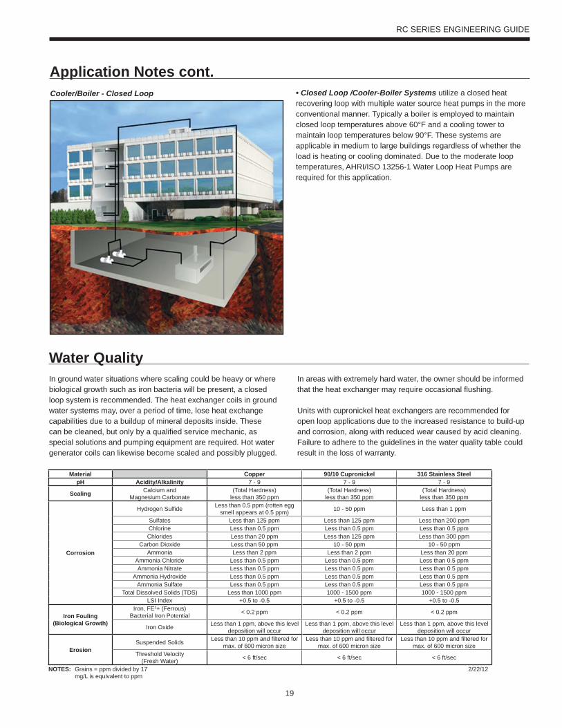
• Closed Loop /Cooler-Boiler Systems utilize a closed heat recovering loop with multiple water source heat pumps in the more conventional manner. Typically a boiler is employed to maintain closed loop temperatures above 60°F and a cooling tower to maintain loop temperatures below 90°F. These systems are applicable in medium to large buildings regardless of whether the load is heating or cooling dominated. Due to the moderate loop temperatures, AHRI/ISO 13256-1 Water Loop Heat Pumps are required for this application.
Cooler/Boiler - Closed Loop
Application Notes cont.
In ground water situations where scaling could be heavy or where biological growth such as iron bacteria will be present, a closed loop system is recommended. The heat exchanger coils in ground water systems may, over a period of time, lose heat exchange capabilities due to a buildup of mineral deposits inside. These can be cleaned, but only by a qualified service mechanic, as special solutions and pumping equipment are required. Hot water generator coils can likewise become scaled and possibly plugged.
Water Quality
Material Copper 90/10 Cupronickel 316 Stainless SteelpH Acidity/Alkalinity 7 - 9 7 - 9 7 - 9
Scaling Calcium andMagnesium Carbonate
(Total Hardness)less than 350 ppm
(Total Hardness)less than 350 ppm
(Total Hardness)less than 350 ppm
Corrosion
Hydrogen Sulfide Less than 0.5 ppm (rotten egg smell appears at 0.5 ppm) 10 - 50 ppm Less than 1 ppm
Sulfates Less than 125 ppm Less than 125 ppm Less than 200 ppmChlorine Less than 0.5 ppm Less than 0.5 ppm Less than 0.5 ppmChlorides Less than 20 ppm Less than 125 ppm Less than 300 ppm
Carbon Dioxide Less than 50 ppm 10 - 50 ppm 10 - 50 ppmAmmonia Less than 2 ppm Less than 2 ppm Less than 20 ppm
Ammonia Chloride Less than 0.5 ppm Less than 0.5 ppm Less than 0.5 ppmAmmonia Nitrate Less than 0.5 ppm Less than 0.5 ppm Less than 0.5 ppm
Ammonia Hydroxide Less than 0.5 ppm Less than 0.5 ppm Less than 0.5 ppmAmmonia Sulfate Less than 0.5 ppm Less than 0.5 ppm Less than 0.5 ppm
Total Dissolved Solids (TDS) Less than 1000 ppm 1000 - 1500 ppm 1000 - 1500 ppmLSI Index +0.5 to -0.5 +0.5 to -0.5 +0.5 to -0.5
Iron Fouling(Biological Growth)
Iron, FE2+ (Ferrous)Bacterial Iron Potential < 0.2 ppm < 0.2 ppm < 0.2 ppm
Iron Oxide Less than 1 ppm, above this level deposition will occur
Less than 1 ppm, above this level deposition will occur
Less than 1 ppm, above this level deposition will occur
ErosionSuspended Solids Less than 10 ppm and filtered for
max. of 600 micron sizeLess than 10 ppm and filtered for
max. of 600 micron sizeLess than 10 ppm and filtered for
max. of 600 micron sizeThreshold Velocity
(Fresh Water) < 6 ft/sec < 6 ft/sec < 6 ft/sec
NOTES: Grains = ppm divided by 17mg/L is equivalent to ppm
2/22/12
In areas with extremely hard water, the owner should be informed that the heat exchanger may require occasional flushing.
Units with cupronickel heat exchangers are recommended for open loop applications due to the increased resistance to build-up and corrosion, along with reduced wear caused by acid cleaning. Failure to adhere to the guidelines in the water quality table could result in the loss of warranty.
20
RC SERIES ENGINEERING GUIDE
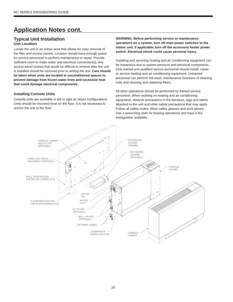
Typical Unit InstallationUnit LocationLocate the unit in an indoor area that allows for easy removal of the filter and access panels. Location should have enough space for service personnel to perform maintenance or repair. Provide sufficient room to make water and electrical connection(s). Any access panel screws that would be difficult to remove after the unit is installed should be removed prior to setting the unit. Care should be taken when units are located in unconditioned spaces to prevent damage from frozen water lines and excessive heat that could damage electrical components.
Installing Console UnitsConsole units are available in left or right air return configurations. Units should be mounted level on the floor. It is not necessary to anchor the unit to the floor.
WARNING: Before performing service or maintenance operations on a system, turn off main power switches to the indoor unit. If applicable, turn off the accessory heater power switch. Electrical shock could cause personal injury.
Installing and servicing heating and air conditioning equipment can be hazardous due to system pressure and electrical components. Only trained and qualified service personnel should install, repair or service heating and air conditioning equipment. Untrained personnel can perform the basic maintenance functions of cleaning coils and cleaning and replacing filters.
All other operations should be performed by trained service personnel. When working on heating and air conditioning equipment, observe precautions in the literature, tags and labels attached to the unit and other safety precautions that may apply. Follow all safety codes. Wear safety glasses and work gloves. Use a quenching cloth for brazing operations and have a fire extinguisher available.
Application Notes cont.
21
RC SERIES ENGINEERING GUIDE
Water PipingPiping is usually design as ‘reverse return’ to equalize flow paths through each unit. A short flexible pressure rated hose is used to make connection to the fixed building piping system. This hose is typically stainless steel braid and includes a swivel fitting on one end for easy removal and is flexible to help isolate the unit for quieter operation . Isolation valves for servicing, y-strainers for filtering and memory-stop flow valve or a balancing valve can be provided for consistent water flow through the unit.
All unit source water connections are fittings that accept a male pipe thread (MPT). Insert the connectors by hand, then tighten the fitting with a wrench to provide a leakproof joint. The open and closed loop piping system should include pressure/temperature ports for serviceability. The proper water flow must be provided to each unit whenever the unit operates. To assure proper flow, use pressure/temperature ports to determine the flow rate. These ports should be located at the supply and return water connections on the unit. The proper flow rate cannot be accurately set without measuring the water pressure drop through the refrigerant-to-water heat exchanger. Check carefully for water leaks.
Condensate DrainOn console units, the internal condensate drain assembly consists of a drain tube which is connected to the drain pan. A condensate tube is inside all cabinets as a trapping loop; therefore, an external trap is not necessary.
Application Notes cont.
22
RC SERIES ENGINEERING GUIDE
To achieve optimal performance, proper selection of each heat pump is essential. A building load program should be used to determine the heating and cooling load of each zone. A computer software selection program can then be used to develop an accurate and complete heat pump schedule. Software can be obtained from your local representative.
While a software program is the easiest and most accurate method to size and select equipment, however, selection can still be accomplished manually using this manual and the following selection procedure. Sizing so that the actual sensible capacity of the equipment will satisfy the sensible capacity of the zone is the recommended method for best results.
Boiler/Tower ApplicationTypical boiler/tower application will result in entering water temperatures of 60-90°F with 70°F for heating and 90°F for cooling. Water to refrigerant insulation option would not be required. Flow rates are 2.5 to 3 gpm per ton with 2.5 gpm per ton often representing an economical design point.
Geothermal ApplicationTypical geothermal application can result in a wide entering water temperature range of 30-100°F. Typically minimum heating entering water temperatures can range from 30 to 50°F depending upon loop type and geographical location. Cooling performance should be calculated using a maximum loop temperature of 100°F in most loop applications. Water flow is typically 2.5 to 3 gpm per ton with 3 gpm per ton recommended with the more extreme loop temperatures. PLEASE NOTE THAT WATER COIL INSULATION OPTION SHOULD BE SELECTED WHEN ENTERING WATER TEMPERATURES ARE EXPECTED TO BE BELOW 45-50°F.
Geothermal Selection ExampleStep 1: Determine the actual heating and cooling loads at the desired dry bulb and wet bulb conditions.
Step 2: Obtain the following de sign parameters: Entering water temperature, water flow rate in GPM, air flow in CFM, water flow pressure drop and design wet and dry bulb temperatures. Air flow CFM should be between 300 and 450 CFM per ton. Unit water pressure drop should be kept as close as possible to each other to make water balancing easier. Go to the appropriate tables and find the proper indicated water flow and water temperature.
Step 3: Select a unit based on total and sensible cooling conditions. Select a unit which is closest to, but no larger than, the actual cooling load.Step 4: Enter tables at the design water flow and water temperature. Read the total and sensible cooling capacities (Note: interpolation is permissible, extrapolation is not).
Step 5: Read the heating capacity. If it exceeds the design criteria it is acceptable. It is quite normal for water source heat pumps to
be selected on cooling capacity only since the heating output is usually greater than the cooling capacity.
Step 6: Determine the correction factors associated with the variable factors of dry bulb and wet bulb. Corrected Total Cooling = tabulated total cooling x wet bulb correction.Corrected Sensible Cooling = tabulated sensible cooling x wet/dry bulb correction.
Step 7: Compare the corrected capacities to the load requirements. Normally if the capacities are within 10% of the loads, the equipment is acceptable. It is better to undersize than oversize, as undersizing improves humidity control, reduces sound levels and extends the life of the equipment.
Step 8: When complete, calculate water temperature rise and assess the selection. If the units selected are not within 10% of the load calculations, then review what effect changing the GPM, water temperature and/or air flow and air temperature would have on the corrected capacities. If the desired capacity cannot be achieved, select the next larger or smaller unit and repeat the procedure. Remember, when in doubt, undersize slightly for best performance.
Example Equipment Selection - Cooling1. Load Determination:Assume we have determined that the appropriate cooling load at the desired dry bulb 75°F and wet bulb 60°F conditions is as follows:Total Cooling ............................................................ 14,800 BTUHSensible Cooling.......................................................11,200 BTUHEntering Air Temp ..........................75°F Dry Bulb / 60°F Wet Bulb
2. Design Conditions:Similarly, we have also obtained the following design parameters:Entering Water Temp ............................................................100°FWater Flow (Based upon 10°F rise in temp.) 5.5 GPMAir Flow Required ........................................................... 450 CFM
3, 4 & 5. HP Selection:After making our preliminary selection (RC18), we enter the tables at design water flow and water temperature and readTotal Cooling, Sens. Cooling and Heat of Rej. capacities:Total Cooling ............................................................ 16,600 BTUHSensible Cooling...................................................... 12,600 BTUHHeat of Rejection ..................................................... 21,400 BTUH
6 & 7. Entering Air and Airflow Corrections:Next, we determine our correction factors. (Refer to Correction Factor Tables - Air Flow and Entering Air correction tables — using 450 cfm. or 450÷500 nom. = 90%).Corrected Total Cooling = 16,600 x 0.982 x 0.897 = 14,622Corrected Sens Cooling = 12,600 x 0.933 x 0.995 = 11,697Corrected Heat of Reject = 21,400 x 0.980 x 0.895 = 18,770
Selection Example
23
RC SERIES ENGINEERING GUIDE
8. Water Temperature Rise Calculation & Assessment: Note: 500 = parameters for water & 485 = parameters for antifreeze solutions to 30% weight.
When we compare the Corrected Total Cooling and Corrected Sensible Cooling figures with our load requirements stated in Step 1, we discover that our selection is within +10% of our sensible load requirement. Further more, we see that our Corrected Total Cooling figure is within 1,000 Btuh of the actual indicated load.
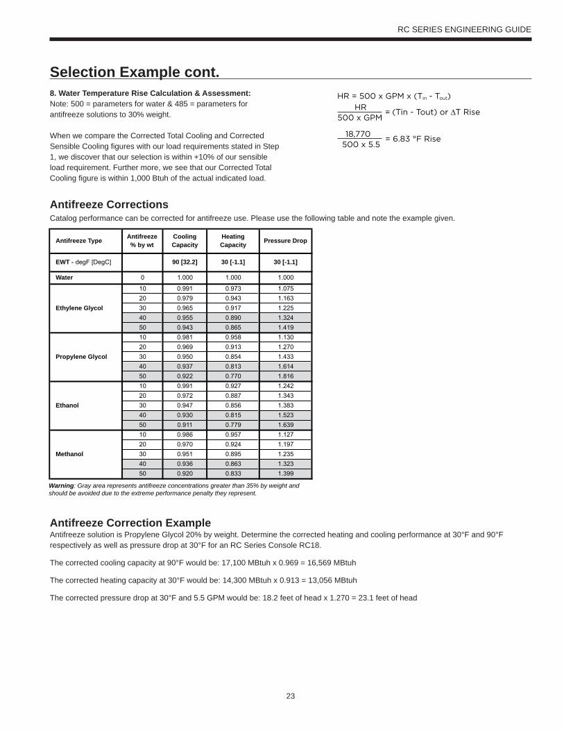
Antifreeze CorrectionsCatalog performance can be corrected for antifreeze use. Please use the following table and note the example given.
Antifreeze Correction ExampleAntifreeze solution is Propylene Glycol 20% by weight. Determine the corrected heating and cooling performance at 30°F and 90°F respectively as well as pressure drop at 30°F for an RC Series Console RC18.
The corrected cooling capacity at 90°F would be: 17,100 MBtuh x 0.969 = 16,569 MBtuh
The corrected heating capacity at 30°F would be: 14,300 MBtuh x 0.913 = 13,056 MBtuh
The corrected pressure drop at 30°F and 5.5 GPM would be: 18.2 feet of head x 1.270 = 23.1 feet of head
Antifreeze Type Antifreeze% by wt
Cooling Capacity
Heating Capacity Pressure Drop
EWT - degF [DegC] 90 [32.2] 30 [-1.1] 30 [-1.1]
Water 0 1.000 1.000 1.000
10 0.991 0.973 1.075
20 0.979 0.943 1.163
Ethylene Glycol 30 0.965 0.917 1.225
40 0.955 0.890 1.324
50 0.943 0.865 1.419
10 0.981 0.958 1.130
20 0.969 0.913 1.270
Propylene Glycol 30 0.950 0.854 1.433
40 0.937 0.813 1.614
50 0.922 0.770 1.816
10 0.991 0.927 1.242
20 0.972 0.887 1.343
Ethanol 30 0.947 0.856 1.383
40 0.930 0.815 1.523
50 0.911 0.779 1.639
10 0.986 0.957 1.127
20 0.970 0.924 1.197
Methanol 30 0.951 0.895 1.235
40 0.936 0.863 1.323
50 0.920 0.833 1.399
Warning: Gray area represents antifreeze concentrations greater than 35% by weight and should be avoided due to the extreme performance penalty they represent.
= ∆
Selection Example cont.
24
RC SERIES ENGINEERING GUIDE
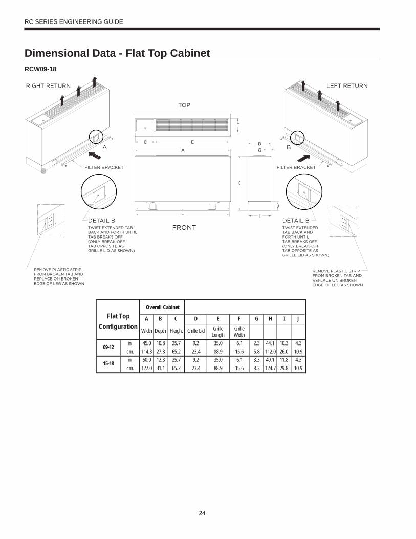
RCW09-18
Overall CabinetFlat Top
ConfigurationA B C D E F G H I J
Width Depth Height Grille Lid Grille Length
Grille Width
in. 45.0 10.8 25.7 9.2 35.0 6.1 2.3 44.1 10.3 4.3cm. 114.3 27.3 65.2 23.4 88.9 15.6 5.8 112.0 26.0 10.9in. 50.0 12.3 25.7 9.2 35.0 6.1 3.3 49.1 11.8 4.3
cm. 127.0 31.1 65.2 23.4 88.9 15.6 8.3 124.7 29.8 10.9
09-12
15-18
F
B
G
I
J
C
ED
A
H
FILTER BRACKET FILTER BRACKET
RIGHT RETURN
TOP
FRONT
LEFT RETURN
DETAIL BTWIST EXTENDEDTAB BACK ANDFORTH UNTILTAB BREAKS OFF(ONLY BREAK-OFFTAB OPPOSITE ASGRILLE LID AS SHOWN)
DETAIL BTWIST EXTENDED TABBACK AND FORTH UNTILTAB BREAKS OFF(ONLY BREAK-OFFTAB OPPOSITE ASGRILLE LID AS SHOWN)
BA
REMOVE PLASTIC STRIPFROM BROKEN TAB ANDREPLACE ON BROKENEDGE OF LEG AS SHOWN
REMOVE PLASTIC STRIPFROM BROKEN TAB ANDREPLACE ON BROKENEDGE OF LEG AS SHOWN
Dimensional Data - Flat Top Cabinet

25
RC SERIES ENGINEERING GUIDE
RCS09-18
Overall CabinetSlope Top
ConfigurationA B C D E F G H I J
Width Depth Height Grille Lid Grille Length
Grille Width
in. 45.0 11.1 28.6 9.2 35.0 6.1 2.8 44.1 10.3 4.3cm. 114.3 28.2 72.6 23.4 88.9 15.6 7.2 112.0 26.0 10.9in. 50.0 12.6 29.1 9.2 35.0 6.1 2.5 49.1 11.8 4.3
cm. 127.0 32.0 73.9 23.4 88.9 15.6 6.4 124.7 29.8 10.9
09-12
15-18
Dimensional Data - Slope Top Cabinet
26
RC SERIES ENGINEERING GUIDE
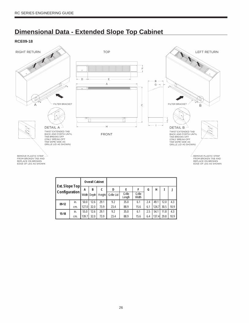
RCE09-18
Overall CabinetExt. Slope Top
Configuration A B C D E F G H I JWidth Depth Height Grille Lid Grille
LengthGrille Width
in. 50.0 12.6 29.1 9.2 35.0 6.1 2.4 49.1 12.0 4.3cm. 127.0 32.0 73.9 23.4 88.9 15.6 6.1 124.7 30.5 10.9in. 55.0 12.6 29.1 9.2 35.0 6.1 2.5 54.1 11.8 4.3
cm. 139.7 32.0 73.9 23.4 88.9 15.6 6.4 137.4 29.8 10.9
09-12
15-18
Dimensional Data - Extended Slope Top Cabinet
27
RC SERIES ENGINEERING GUIDE
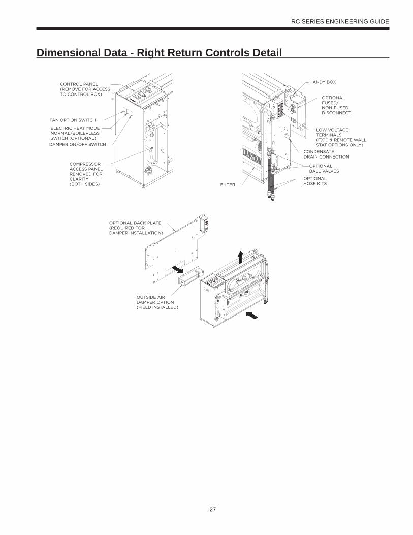
Dimensional Data - Right Return Controls Detail
28
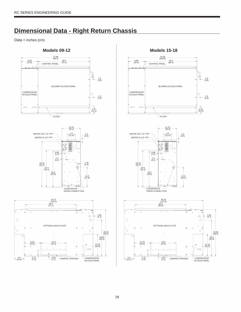
RC SERIES ENGINEERING GUIDE
BLOWER ACCESS PANEL
COMPRESSORACCESS PANEL
37.88(96.2)
28.5(72.4)
1.5(3.8)
1.5(3.8)
4.37(11.1)
9.38(23.8)
FILTER
CONTROL PANEL
25.25(64.1)
0.86(2.2)
10.31(26.2)
1.0(2.5)
1.78(4.5)
11.0(27.9)
4.5(11.4)
2.0(5.1)
21.4(54.4)
20.0(50.8)
CONDENSATEDRAIN CONNECTION
WATER OUT 1/2˝ FPT
WATER IN 1/2˝ FPT
OPTIONAL BACK PLATE
COMPRESSORACCESS PANEL
43.37(110.2)
28.0(71.1)
9.25(23.5)
13.9(35.3)
25.65(65.2)
19.83(50.4)
1.64(4.2)
12.03(30.6)
0.66(1.7)
2.75(7.0)
5.5(14.0) DAMPER OPENING
Models 09-12
BLOWER ACCESS PANEL
COMPRESSORACCESS PANEL
42.88(108.9)
34.0(86.4)
1.5(3.8)
1.5(3.8)
4.32(11.0)
8.88(22.6)
FILTER
CONTROL PANEL
25.25(64.1)
0.86(2.2)
11.75(29.8)
1.0(2.5)
12.0(30.5)
4.5(11.4)
2.0(5.1)
20.6(52.3)
19.5(49.5)
CONDENSATEDRAIN CONNECTION
WATER OUT 1/2˝ FPT
WATER IN 1/2˝ FPT
OPTIONAL BACK PLATE
COMPRESSORACCESS PANEL
48.25(122.6)
33.0(83.8)
11.78(29.9)
13.9(35.3)
25.80(65.5)
20.0(50.8)
1.62(4.1)
12.18(30.9)
0.83(2.1)
2.75(7.0)
5.4(13.7) DAMPER OPENING
Models 15-18
Data = inches (cm)
Dimensional Data - Right Return Chassis

29
RC SERIES ENGINEERING GUIDE
Dimensional Data - Left Return Controls Detail
30
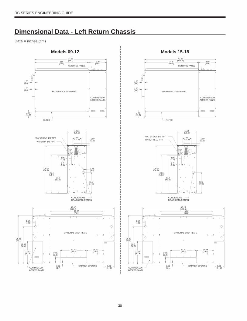
RC SERIES ENGINEERING GUIDE
9.38(23.8)
28.5(72.4)
1.50(3.8)
1.50(3.8)
4.37(11.1)
37.88(96.2)
BLOWER ACCESS PANEL
COMPRESSORACCESS PANEL
FILTER
CONTROL PANEL
1.00(2.5)
10.31(26.2)
4.5(11.4)
0.86(2.2)
2.0(5.1)
25.25(64.1)
21.4(54.4)
20.0(50.8)
1.78(4.5)
11.0(27.9)
CONDENSATEDRAIN CONNECTION
WATER OUT 1/2˝ FPT
WATER IN 1/2˝ FPT
28.00(71.1)
13.90(35.3)
9.25(23.5)
2.75(7.0)
12.03(30.5)
0.66(1.7)
5.50(14.0)
OPTIONAL BACK PLATE
COMPRESSORACCESS PANEL
DAMPER OPENING
43.37(110.2)
1.62(4.1)
25.65(65.1)
19.83(50.4)
Models 09-12
8.88(22.6)
34.0(86.4)
1.50(3.8)
1.50(3.8)
4.32(11.0)
42.88(108.9)
BLOWER ACCESS PANEL
COMPRESSORACCESS PANEL
FILTER
CONTROL PANEL
1.00(2.5)
11.75(26.2)
4.5(11.4)
0.86(2.2)
2.0(5.1)
25.25(64.1)
20.6(52.3)
19.5(49.5)
12.0(30.5)
CONDENSATEDRAIN CONNECTION
WATER OUT 1/2˝ FPTWATER IN 1/2˝ FPT
33.0(83.8)
13.90(35.3)
11.78(29.9)
2.75(7.0)
12.18(30.9)
0.83(2.1)
5.50(14.0)
OPTIONAL BACK PLATE
COMPRESSORACCESS PANEL
DAMPER OPENING
48.25(122.6)
1.62(4.1)
25.80(65.5)
20.0(50.8)
Models 15-18
Data = inches (cm)
Dimensional Data - Left Return Chassis
31
RC SERIES ENGINEERING GUIDE
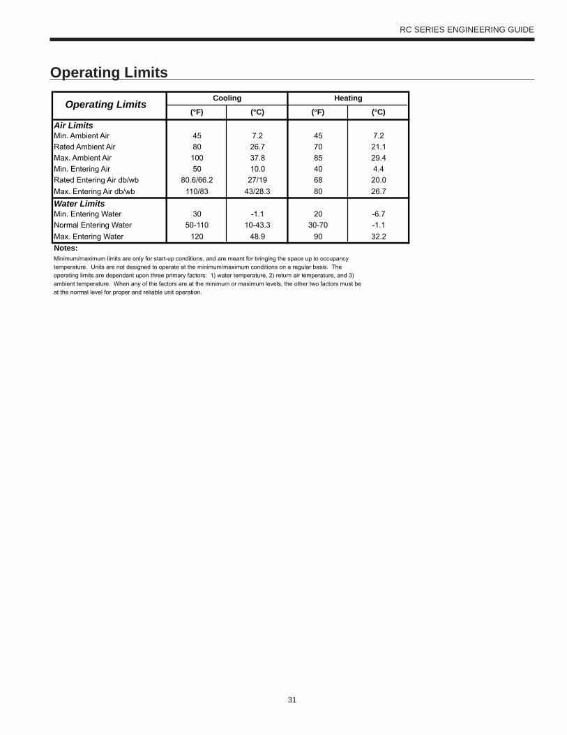
Operating Limits(°F) (°C) (°F) (°C)
Air LimitsMin. Ambient Air 45 7.2 45 7.2
Rated Ambient Air 80 26.7 70 21.1
Max. Ambient Air 100 37.8 85 29.4
Min. Entering Air 50 10.0 40 4.4
Rated Entering Air db/wb 80.6/66.2 27/19 68 20.0
Max. Entering Air db/wb 110/83 43/28.3 80 26.7
Water LimitsMin. Entering Water 30 -1.1 20 -6.7
Normal Entering Water 50-110 10-43.3 30-70 -1.1
Max. Entering Water 120 48.9 90 32.2
Notes:
Cooling Heating
Minimum/maximum limits are only for start-up conditions, and are meant for bringing the space up to occupancy
temperature. Units are not designed to operate at the minimum/maximum conditions on a regular basis. The
operating limits are dependant upon three primary factors: 1) water temperature, 2) return air temperature, and 3)
ambient temperature. When any of the factors are at the minimum or maximum levels, the other two factors must be
at the normal level for proper and reliable unit operation.
Operating Limits
32
RC SERIES ENGINEERING GUIDE
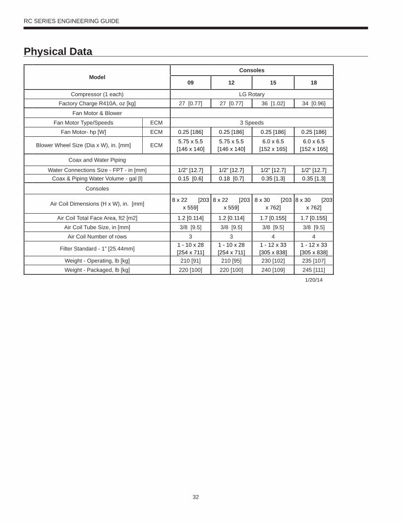
Physical Data
ModelConsoles
09 12 15 18
Compressor (1 each) LG RotaryFactory Charge R410A, oz [kg] 27 [0.77] 27 [0.77] 36 [1.02] 34 [0.96]
Fan Motor & Blower
Fan Motor Type/Speeds ECM 3 SpeedsFan Motor- hp [W] ECM 0.25 [186] 0.25 [186] 0.25 [186] 0.25 [186]
Blower Wheel Size (Dia x W), in. [mm] ECM5.75 x 5.5
[146 x 140]5.75 x 5.5
[146 x 140]6.0 x 6.5
[152 x 165]6.0 x 6.5
[152 x 165]
Coax and Water Piping
Water Connections Size - FPT - in [mm] 1/2” [12.7] 1/2” [12.7] 1/2” [12.7] 1/2” [12.7]Coax & Piping Water Volume - gal [l] 0.15 [0.6] 0.18 [0.7] 0.35 [1.3] 0.35 [1.3]
Consoles
Air Coil Dimensions (H x W), in. [mm]8 x 22 [203
x 559]8 x 22 [203
x 559]8 x 30 [203
x 762]8 x 30 [203
x 762]
Air Coil Total Face Area, ft2 [m2] 1.2 [0.114] 1.2 [0.114] 1.7 [0.155] 1.7 [0.155]Air Coil Tube Size, in [mm] 3/8 [9.5] 3/8 [9.5] 3/8 [9.5] 3/8 [9.5]
Air Coil Number of rows 3 3 4 4
Filter Standard - 1” [25.44mm]1 - 10 x 28 [254 x 711]
1 - 10 x 28 [254 x 711]
1 - 12 x 33 [305 x 838]
1 - 12 x 33 [305 x 838]
Weight - Operating, lb [kg] 210 [91] 210 [95] 230 [102] 235 [107]Weight - Packaged, lb [kg] 220 [100] 220 [100] 240 [109] 245 [111]
1/20/14
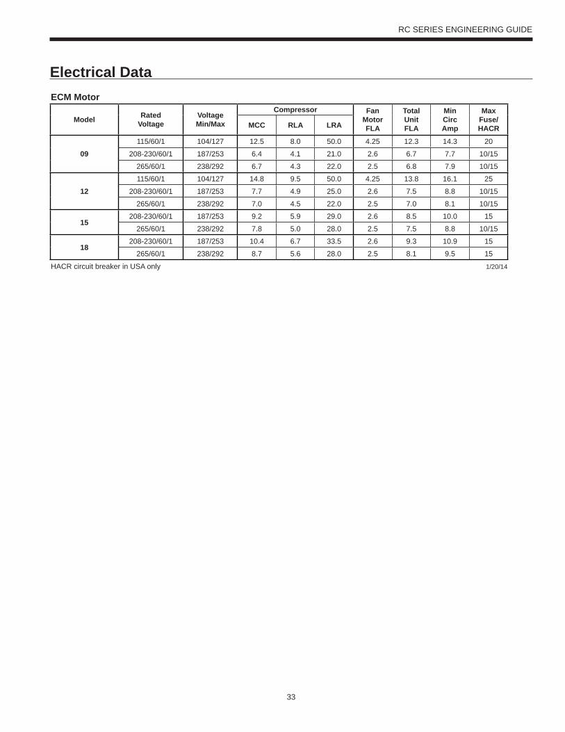
33
RC SERIES ENGINEERING GUIDE
Electrical DataECM Motor
Model RatedVoltage
VoltageMin/Max
Compressor FanMotorFLA
TotalUnitFLA
MinCircAmp
MaxFuse/HACRMCC RLA LRA
09115/60/1 104/127 12.5 8.0 50.0 4.25 12.3 14.3 20
208-230/60/1 187/253 6.4 4.1 21.0 2.6 6.7 7.7 10/15
265/60/1 238/292 6.7 4.3 22.0 2.5 6.8 7.9 10/15
12115/60/1 104/127 14.8 9.5 50.0 4.25 13.8 16.1 25
208-230/60/1 187/253 7.7 4.9 25.0 2.6 7.5 8.8 10/15
265/60/1 238/292 7.0 4.5 22.0 2.5 7.0 8.1 10/15
15208-230/60/1 187/253 9.2 5.9 29.0 2.6 8.5 10.0 15
265/60/1 238/292 7.8 5.0 28.0 2.5 7.5 8.8 10/15
18208-230/60/1 187/253 10.4 6.7 33.5 2.6 9.3 10.9 15
265/60/1 238/292 8.7 5.6 28.0 2.5 8.1 9.5 15
HACR circuit breaker in USA only 1/20/14
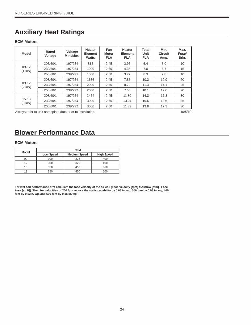
34
RC SERIES ENGINEERING GUIDE
Auxiliary Heat Ratings
Blower Performance Data
ECM Motors
Model RatedVoltage
VoltageMin./Max.
HeaterElement
Watts
Fan MotorFLA
HeaterElement
FLA
TotalUnitFLA
Min.CircuitAmp.
Max.Fuse/Brkr.
09-12(1 kW)
208/60/1 197/254 818 2.45 3.93 6.4 8.0 10230/60/1 197/254 1000 2.60 4.35 7.0 8.7 15265/60/1 239/291 1000 2.50 3.77 6.3 7.8 10
09-12(2 kW)
208/60/1 197/254 1636 2.45 7.86 10.3 12.9 20230/60/1 197/254 2000 2.60 8.70 11.3 14.1 25265/60/1 239/292 2000 2.50 7.55 10.1 12.6 20
15-18(3 kW)
208/60/1 197/254 2454 2.45 11.80 14.3 17.8 30230/60/1 197/254 3000 2.60 13.04 15.6 19.6 35265/60/1 239/292 3000 2.50 11.32 13.8 17.3 30
Always refer to unit nameplate data prior to installation. 10/5/10
For wet coil performance fi rst calculate the face velocity of the air coil (Face Velocity [fpm] = Airfl ow [cfm] / Face Area [sq ft]). Then for velocities of 200 fpm reduce the static capability by 0.03 in. wg, 300 fpm by 0.08 in. wg, 400 fpm by 0.12in. wg. and 500 fpm by 0.16 in. wg.
ECM Motors
ModelCFM
Low Speed Medium Speed High Speed09 300 325 40012 300 325 40015 350 450 60018 350 450 600
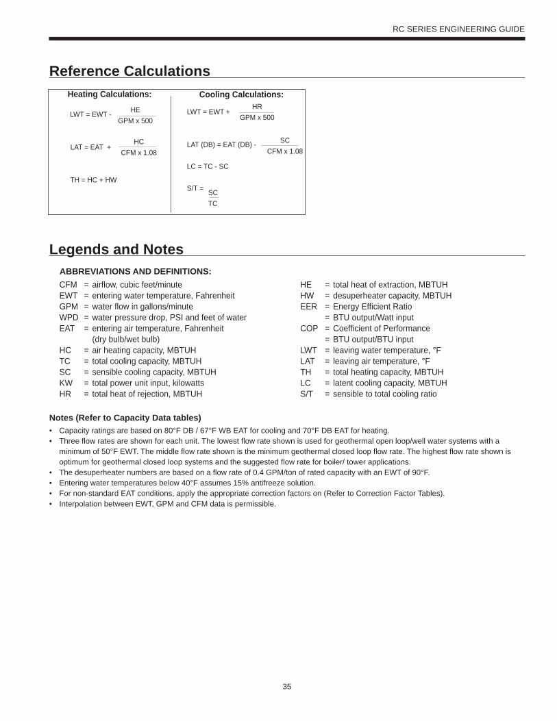
35
RC SERIES ENGINEERING GUIDE
Heating Calculations: Cooling Calculations:
LWT = EWT +
LAT (DB) = EAT (DB) -
LC = TC - SC
S/T =
HRGPM x 500
SCCFM x 1.08
SCTC
LWT = EWT -
LAT = EAT +
TH = HC + HW
HEGPM x 500
HCCFM x 1.08
ABBREVIATIONS AND DEFINITIONS:CFM = airflow, cubic feet/minuteEWT = entering water temperature, FahrenheitGPM = water flow in gallons/minuteWPD = water pressure drop, PSI and feet of waterEAT = entering air temperature, Fahrenheit (dry bulb/wet bulb)HC = air heating capacity, MBTUHTC = total cooling capacity, MBTUHSC = sensible cooling capacity, MBTUHKW = total power unit input, kilowattsHR = total heat of rejection, MBTUH
HE = total heat of extraction, MBTUHHW = desuperheater capacity, MBTUHEER = Energy Efficient Ratio = BTU output/Watt inputCOP = Coefficient of Performance = BTU output/BTU inputLWT = leaving water temperature, °FLAT = leaving air temperature, °FTH = total heating capacity, MBTUHLC = latent cooling capacity, MBTUHS/T = sensible to total cooling ratio
Notes (Refer to Capacity Data tables)• Capacity ratings are based on 80°F DB / 67°F WB EAT for cooling and 70°F DB EAT for heating.• Three flow rates are shown for each unit. The lowest flow rate shown is used for geothermal open loop/well water systems with a minimum of 50°F EWT. The middle flow rate shown is the minimum geothermal closed loop flow rate. The highest flow rate shown is optimum for geothermal closed loop systems and the suggested flow rate for boiler/ tower applications. • The desuperheater numbers are based on a flow rate of 0.4 GPM/ton of rated capacity with an EWT of 90°F.• Entering water temperatures below 40°F assumes 15% antifreeze solution. • For non-standard EAT conditions, apply the appropriate correction factors on (Refer to Correction Factor Tables). • Interpolation between EWT, GPM and CFM data is permissible.
Reference Calculations
Legends and Notes
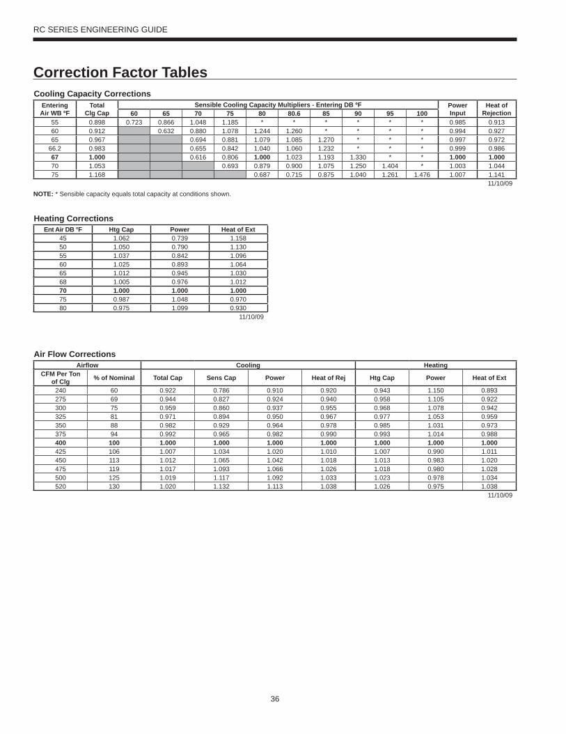
36
RC SERIES ENGINEERING GUIDE
Correction Factor TablesCooling Capacity Corrections
EnteringAir WB ºF
TotalClg Cap
Sensible Cooling Capacity Multipliers - Entering DB ºF PowerInput
Heat ofRejection60 65 70 75 80 80.6 85 90 95 100
55 0.898 0.723 0.866 1.048 1.185 * * * * * * 0.985 0.91360 0.912 0.632 0.880 1.078 1.244 1.260 * * * * 0.994 0.92765 0.967 0.694 0.881 1.079 1.085 1.270 * * * 0.997 0.972
66.2 0.983 0.655 0.842 1.040 1.060 1.232 * * * 0.999 0.98667 1.000 0.616 0.806 1.000 1.023 1.193 1.330 * * 1.000 1.00070 1.053 0.693 0.879 0.900 1.075 1.250 1.404 * 1.003 1.04475 1.168 0.687 0.715 0.875 1.040 1.261 1.476 1.007 1.141
11/10/09NOTE: * Sensible capacity equals total capacity at conditions shown.
Air Flow CorrectionsAirflow Cooling Heating
CFM Per Ton of Clg % of Nominal Total Cap Sens Cap Power Heat of Rej Htg Cap Power Heat of Ext
240 60 0.922 0.786 0.910 0.920 0.943 1.150 0.893275 69 0.944 0.827 0.924 0.940 0.958 1.105 0.922300 75 0.959 0.860 0.937 0.955 0.968 1.078 0.942325 81 0.971 0.894 0.950 0.967 0.977 1.053 0.959350 88 0.982 0.929 0.964 0.978 0.985 1.031 0.973375 94 0.992 0.965 0.982 0.990 0.993 1.014 0.988400 100 1.000 1.000 1.000 1.000 1.000 1.000 1.000425 106 1.007 1.034 1.020 1.010 1.007 0.990 1.011450 113 1.012 1.065 1.042 1.018 1.013 0.983 1.020475 119 1.017 1.093 1.066 1.026 1.018 0.980 1.028500 125 1.019 1.117 1.092 1.033 1.023 0.978 1.034520 130 1.020 1.132 1.113 1.038 1.026 0.975 1.038
11/10/09
Heating CorrectionsEnt Air DB °F Htg Cap Power Heat of Ext
45 1.062 0.739 1.15850 1.050 0.790 1.13055 1.037 0.842 1.09660 1.025 0.893 1.06465 1.012 0.945 1.03068 1.005 0.976 1.01270 1.000 1.000 1.00075 0.987 1.048 0.97080 0.975 1.099 0.930
11/10/09
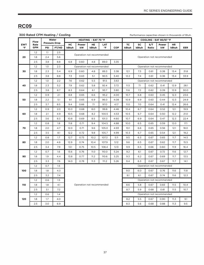
37
RC SERIES ENGINEERING GUIDE
RC09

38
RC SERIES ENGINEERING GUIDE
RC12

39
RC SERIES ENGINEERING GUIDE
RC15
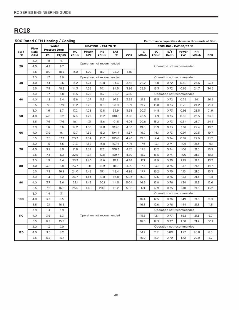
40
RC SERIES ENGINEERING GUIDE
RC18
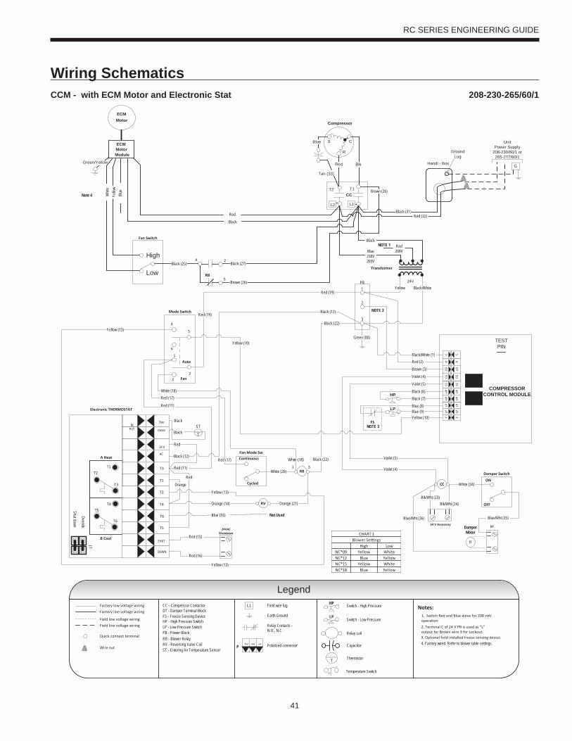
41
RC SERIES ENGINEERING GUIDE
Wiring SchematicsCCM - with ECM Motor and Electronic Stat 208-230-265/60/1
CC
Factory low voltage wiring
Temperature Switch
Factory line voltage wiring
Quick connect terminal
Wire nut
Notes:1. Switch Red and Blue wires for 208 volt operationField low voltage wiring
Field line voltage wiring
LP
HP
Handi - Box
GroundLug
Cycled
Continuous
CCT2 T1
Compressor
C
R
S
Tan (33)
Red Blk
Blue
L1L2
High
Low
Auto
Fan
6
1
32
4
5
COMPRESSORCONTROL MODULE
TESTPIN
HP
HP
CCCG
LOR
CLP
LPY
HP
HP
CCCG
LOR
CLP
LPY
Transformer
24V
Blue230V265V
Red208V
Black
Yellow Black/White
Black/White (1)Red (2)
Brown (3)
Black (6)Black (7)
Blue (8)Blue (9)
Ther
mistor
Electronic THERMOSTAT
T1
T3
B Cool
A Heat
T2
T4
T6
T5
SHUT
DOWN
24 V
AC
INPUT
T6
T4T5
T2T1
T3Overide
Shut down
J1Red
Violet (5)
Violet (4)
Yellow (13)
Yellow (10)
White (20)
Orange (14) Orange (21)
Orange
Black (12)
White (18)
Red (11)
Red (19)
Red (17)
24 V Accessory24VAC
ShutdownRed (15)
Red (16)
NOTE 1
T
ST
CC - Compressor Contactor
HP - High Pressure SwitchLP - Low Pressure Switch
RV - Reversing Valve CoilST - Entering Air Temperature Sensor
RB - Blower Relay
Black
Black
Red (11)
Black (12)
Red (17)
Red (19)
Black (25)
Black (31)Red (32)
Brown (26)
RB
4 2
5
Red
RV
DT
ON
OFF
Damper Switch
Damper Motor
D
Fan Mode Sw
Blk/Wht (24)Blk/Wht (23)
Black (22)
White (18)
Blue (T6)
NOTE 2
2. Terminal C of 24 V PB is used as “L”output for Brown wire 3 for Lockout.
31RB Violet (4)
Blue/Wht (36) Blue/Wht (35)
White (34)
Green (00)
FS
Yellow (13)
Not Used
Violet (5)
Yellow (13)
Yellow (10)
Legend
Page 1
Black (22)
Black (27)
Brown (26)
DT - Damper Terminal Block
PB - Power Block
PB1
2
3
Field wire lug
Earth Ground
Relay Contacts -N.O., N.C.
Polarized connector
132
P
Switch - High Pressure
Switch - Low Pressure
Relay coil
Capacitor
Thermistor
HP
LP
T
L1
NOTE 3
3. Optional field installed freeze sensing device.
FS - Freeze Sensing Device
G
UnitPower Supply
208-230/60/1 or265-277/60/1
Mode Switch
Fan Switch
ECMMotorModule
Note 4
ECMMotor
Green/Yellow
Yello
wW
hite
Blue
Red
Black
4. Factory wired. Refer to blower table settings.
High LowNC*09 Yellow WhiteNC*12 Blue YellowNC*15 Yellow WhiteNC*18 Blue Yellow
Blower Se ngsCHART 1
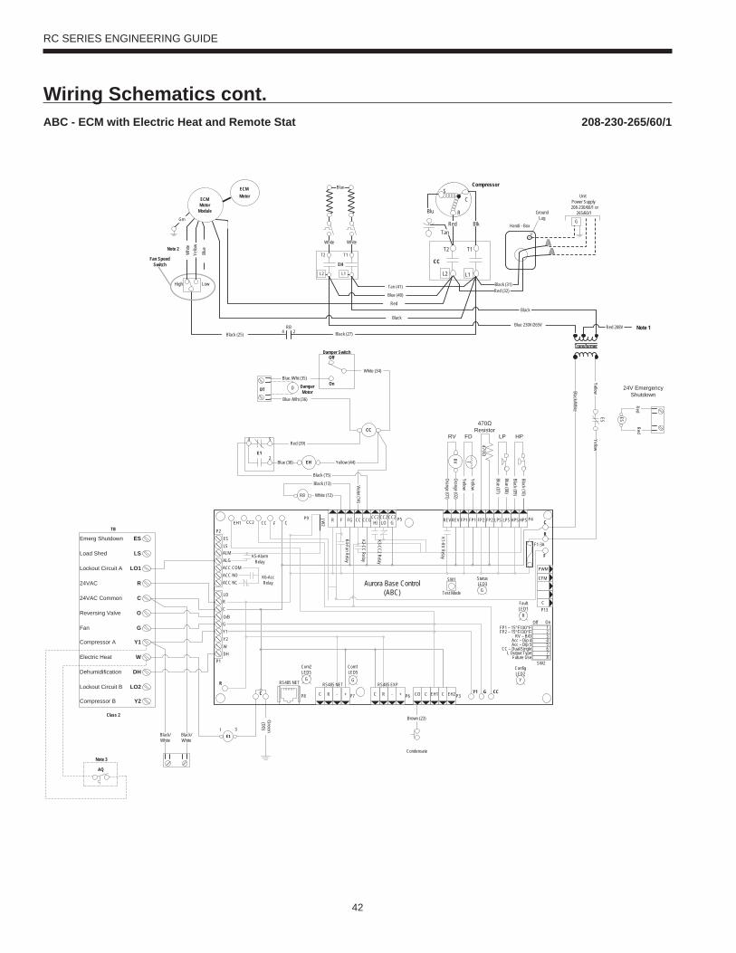
42
RC SERIES ENGINEERING GUIDE
Wiring Schematics cont.ABC - ECM with Electric Heat and Remote Stat 208-230-265/60/1
Transformer
Black (25)Note 1
Compressor
CC
T2
R
SC
BlkRedTan
Blu
L2
T1
L1
Handi - Box
Ground Lug
UnitPower Supply208-230/60/1 or
265/60/1
GGrn
High Low
Fan SpeedSwitch
RB4 2
ECM Motor
Module
ECM Motor
Black
Note 2
CFM
P13
P4
SW1
P5JW2
P9
LO
O/B
Y2WDH
P8 P7
RS485 NET RS485 NET
P6
RS485 EXP
P3
SW2
On
Future Use L Output Type
CC – Dual/SingleAcc – Dip 5Acc – Dip 4
RV – B/OFP2 – 15°F/30°FFP1 – 15°F/30°F
Com1LED5
Com2LED5
Test Mode
F1-3A
P1
C
PWM
12345678
ALMALGACC COMACC NOACC NC
RC
GY1
EH2CEH1CCOC R - +C R - +
Off
FaultLED1
R
StatusLED3
ConfigLED2
CC2 CC F C R F FG CC CCGCC2HI
CC2LO
CC2G REV REV FP1 FP1 FP2 FP2 LPS LPS HPSHPS
Aurora Base Control(ABC)
K1-RV Relay
K2-CC Relay
K3-CC2 Relay
K4-Fan RelayK5-Alarm Relay
K6-Acc Relay
F
R
C
CCGY1C
R
ESLS
P2
EH1
YG G
G
470
470Resistor
Orange (01)
Orange (02)RV
HPLP
T
FDRV
Blue (07)
Blue (08)
Black (09)
Black (10)
Yellow
Yellow
Condensate
Brown (23)Green
(00)
TB
ESEmerg Shutdown
LSLoad Shed
LO1Lockout Circuit A
R24VAC
C24VAC Common
OReversing Valve
GFan
Y1Compressor A
WElectric Heat
DHDehumidification
LO2Lockout Circuit B
Y2Compressor B
Class 2
Black/White
Black/White
Yello
wW
hite
Blue
Tan (41)
E131
AQ
Note 3
EH
T2 T1
L2 L1
Blue
WhiteWhite
Yellow
Red 208V
Black
Blue 230V/265V
Black (31)Red (32)
Blue (40)
Red
Yellow
RedRed
24V EmergencyShutdown
ESES
Black/White
Black (13)
RB White (12)
Damper MotorDT D
White (34)
CC
Damper SwitchOff
OnBlue /Wht (35)
EH
4 5
2E1
Red (39)
Blue (38) Yellow (44)
Blue /Wht (36)
Violet (14)
Black (15)
Black (27)
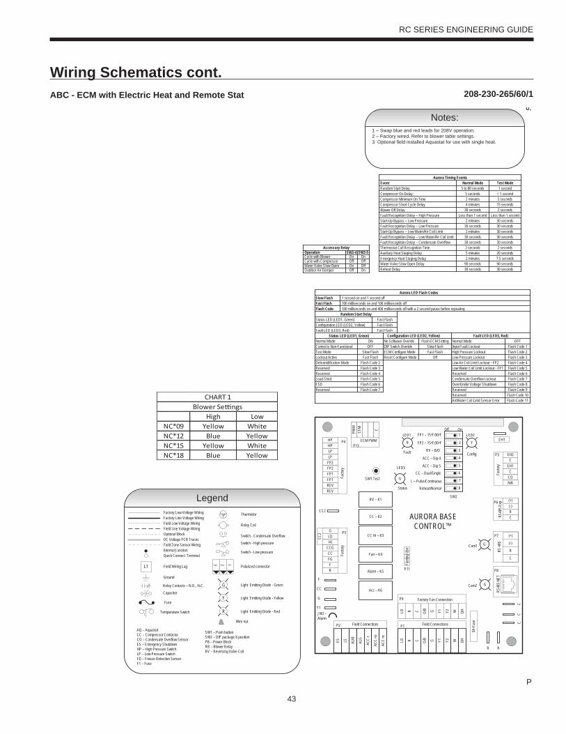
43
RC SERIES ENGINEERING GUIDE
Wiring Schematics cont.208-230-265/60/1ABC - ECM with Electric Heat and Remote Stat
P
05
Wire nut
Temperature Switch
Thermistor
Relay Coil
Switch - Condensate Overflow
Switch - High pressure
Switch - Low pressure
Polarized connector
Factory Low Voltage WiringFactory Line Voltage WiringField Low Voltage WiringField Line Voltage WiringOptional BlockDC Voltage PCB Traces
Internal JunctionQuick Connect Terminal
Field Wiring Lug
Ground
Relay Contacts – N.O., N.C.
Field Zone Sensor Wiring
Legend
L1
Capacitor
T
123
AQ – AquastatCC – Compressor Contactor CO – Condensate Overflow SensorES – Emergency ShutdownHP – High Pressure SwitchLP – Low Pressure Switch FD – Freeze Detection Sensor F1 – Fuse
Fuse
Light Emitting Diode - GreenG
Light Emitting Diode - YellowY
Light Emitting Diode - RedR
SW1 – Push buttonSW2 – DIP package 8 positionPB – Power BlockRB – Blower RelayRV – Reversing Valve Coil
CC2
EH1
Facto
ry
Fault
ALG
ALMLSES ACC
c
Status
AURORA BASE CONTROL™
RV – K1
CC2
CC – K2
CC Hi – K3
Fan – K4
Alarm – K5
Acc – K6
ACC
no
ACC
nc
O/BCRLO G Y1 Y2 W DH
3A-F
use
O/BCRLO G Y1 Y2 W DH
LOG
HICCGCCFGFR
HPHPLP
FP2FP2FP1
REVREV
CFM
PWM
ECM PWM
Facto
ry
Factory Fan Connection
R R
CC
C
C
R
(-)
(+)
RS 48
5
EH2C
EH1C
CO
(+)(-)RCRS
485 E
xpFa
ctory
Com1
Com2
Config
G
G
G
YR
SW1 Test
FP1 – 15oF/30oF
JW2 - Alarm
P11
P5
P2 P1
P8
P7
P9
P6
P3
SW2
P13P4 FP2 – 15oF/30oF
RV – B/O
ACC – Dip 4
ACC – Dip 5
CC – Dual/Single
L – Pulse/Continuous
Reheat/Normal
Facto
ry Us
e
Field ConnectionsField Connections
C
LP
FP1
F
CC
G
Y1
1
2
3
4
5
6
7
8
Off On
N/A
RS48
5 NET
LED3
LED2LED1
High LowNC*09 Yellow WhiteNC*12 Blue YellowNC*15 Yellow WhiteNC*18 Blue Yellow
Blower Se ngsCHART 1
Notes:1 – Swap blue and red leads for 208V operation.2 – Factory wired. Refer to blower table settings.3 Optional field installed Aquastat for use with single heat.
Slow FlashFast FlashFlash Code
Status LED (LED1, Green)Configuration LED (LED2, Yellow)Fault LED (LED3, Red)
Status LED (LED1, Green)Normal ModeControl is Non-FunctionalTest ModeLockout ActiveDehumidification ModeReservedReservedLoad ShedESD
1 second on and 1 second off
Random Start DelayFast Flash
OFFON
Slow FlashFast Flash
Flash Code 2Flash Code 3
Flash Code 6
Flash Code 4Flash Code 5
Aurora LED Flash Codes
100 milliseconds on and 100 milliseconds off100 milliseconds on and 400 milliseconds off with a 2 second pause before repeating
Reserved Flash Code 7
Configuration LED (LED2, Yellow) Fault LED (LED3, Red)
Fast FlashFast Flash
No Software Overide Flash ECM SettingDIP Switch Overide Slow Flash
Normal ModeInput Fault LockoutHigh Pressure LockoutLow Pressure Lockout
Low Water Coil Limit Lockout - FP1Low Air Coil Limit Lockout - FP2
ReservedCondensate Overflow LockoutOver/Under Voltage ShutdownReservedReservedAir/Water Coil Limit Sensor Error
Flash Code 1OFF
Flash Code 2Flash Code 3Flash Code 4Flash Code 5
Flash Code 8
Flash Code 6Flash Code 7
Flash Code 9Flash Code 10Flash Code 11
ECM Configure Mode Fast FlashReset Configure Mode Off
Accessory Relay
Cycle with BlowerCycle with CompressorWater Valve Slow OpenOutdoor Air Damper
SW2-4 SW2-5On OnOff OffOn OffOff On
Operation
Event Normal Mode Test ModeRandom Start DelayCompressor On DelayCompressor Minimum On TimeCompressor Short Cycle DelayBlower Off DelayFault Recognition Delay – High PressureStart-Up Bypass – Low PressureFault Recognition Delay – Low PressureStart-Up Bypass – Low Water/Air Coil LimitFault Recognition Delay – Low Water/Air Coil LimitFault Recognition Delay – Condensate OverflowThermostat Call Recognition TimeAuxiliary Heat Staging DelayEmergency Heat Staging Delay
Less than 1 second
5 to 80 seconds 1 second5 seconds < 1 second
30 seconds 2 secondsLess than 1 second
2 minutes 5 seconds4 minutes 15 seconds
2 minutes
2 minutes
30 seconds30 seconds 30 seconds
30 seconds30 seconds
30 seconds30 seconds30 seconds
2 seconds 2 seconds5 minutes2 minutes
20 seconds7.5 seconds
Aurora Timing Events
Reheat Delay 30 seconds 30 secondsWater Valve Slow Open Delay 90 seconds 90 seconds
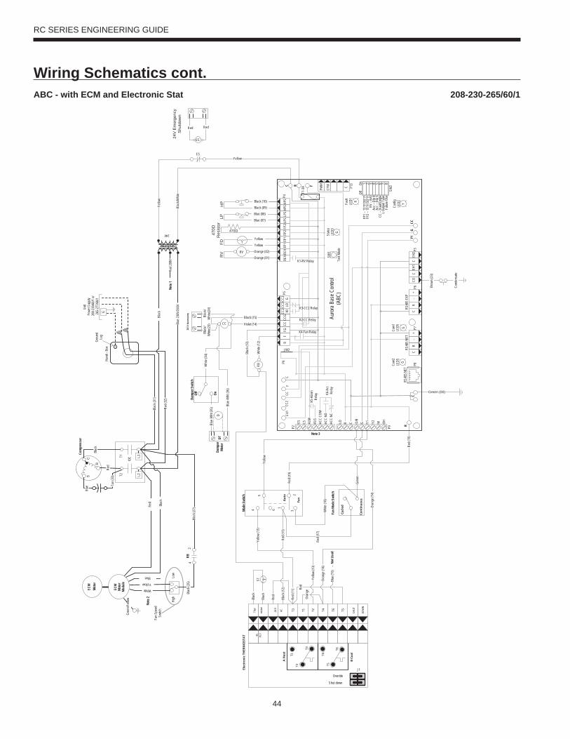
44
RC SERIES ENGINEERING GUIDE
Wiring Schematics cont.208-230-265/60/1ABC - with ECM and Electronic Stat
Com
pres
sor
High
Low
RBRed
Blac
k (25
)4
2
C
ycle
d
Co
ntin
uousA
uto
Fan
6 1
32
4
5
Whit
e (18
)
Red (
17)
Fan S
peed
Sw
itch
CC
L1L2
T1T2
C
R
S
Tan (
33)
Red
Blac
k
Blue
Hand
i - Bo
x
Grou
nd
Lug
Unit
Powe
r Sup
ply20
8-23
0/60/1
or26
5-27
7/60/1
G
24V
Transformer
Th
er
misto
r
Elec
tron
ic T
HER
MO
STA
T
T1T3
B Co
ol
A H
eat
T2 T4 T6 T5 SH
UT
DOW
N
24 V
AC
IN PUT
T6
T4T5T2
T1
T3
Overide
Shut down
J1
Red
Yello
w (1
3)
Oran
ge (1
4)
Oran
ge
TSTBl
ack
Blac
k
Red
Blue
(T6)
Not U
sed
Red (
11)
Blac
k (12
)Re
d (11
)
Yello
w (1
3)
Note
1
Blac
k (31
)
Red (
32)
Blac
k (27
)
Blac
kYe
llow
Blac
k/Whit
e
Red 2
08V
Blue
230V
/265V
Red (
19)
Mode
Swi
tch
Fan
Mode
Swi
tch
Gree
n/Yell
ow
ECM
Moto
rMo
dule
ECM
Moto
r
Note
2
ECM
Moto
rMo
dule
White
Yellow
Blue
Red
Blac
k
CFM P1
3
P4
SW1
P5
JW2
P9
LO O/B
Y2 W DH
P8P7
RS48
5 NET
RS48
5 NET
P6
RS48
5 EXP
P3
SW2On
Futur
e Use
L O
utput
Type
CC –
Dual/
Sing
leAc
c – D
ip 5
Acc –
Dip
4RV
– B/
OFP
2 – 15
°F/3
0°F
FP1 –
15°F
/30°
F
Com1
LED5
Com2
LED5
Test
Mode
F1-3
A
P9
CPWM 1 2 3 4 5 6 7 8
ALM
ALG
ACC
COM
ACC
NOAC
C NC
R C G Y1
EH2
CEH
1C
COC
R-
+C
R-
+
Off
Fault
LED1 R
Statu
sLE
D3
Confi
gLE
D2
CC2
CCF
CR
FFG
CCCC
GCC2
HICC
2LO
CC2 G
REVR
EVFP
1FP
1FP
2FP
2LP
SLP
SHP
SHPS
Auro
ra B
ase C
ontro
l(A
BC)
K1-RV Relay
K2-CC Relay
K3-CC2 Relay
K4-Fan Relay
K5-A
larm
Relay K6
-Acc
Re
lay
FRC
CCG
Y1C
R
ES LS
P2
EH1
YG
G
G470
470
Res
isto
r
Orange (01)
Orange (02)RV
HP
LP
TFDR
VBlue (07)
Blue (08)
Black (09)
Black (10)
Yellow
Yellow
Con
dens
ate
Brow
n (23
)
Green (00)
CC Violet (14)
Black (15)
Blac
k (13
)
RB
Dam
per
Moto
rDT
D
Whit
e (34
)
Dam
per S
witc
hOf
f
On
Whit
e (12
)
Blue
/Wht
(35)
Blue
/Wht
(36)
Yello
w
Gree
n
Yellow
Oran
ge (1
4)
Note 3
RedRed
24V
Em
erge
ncy
Shu
tdow
n
ES
ES
Red (
19)
24 V
Acc
esso
ry Blac
k/W
hite(
24)
Blac
k/W
hite(
23)
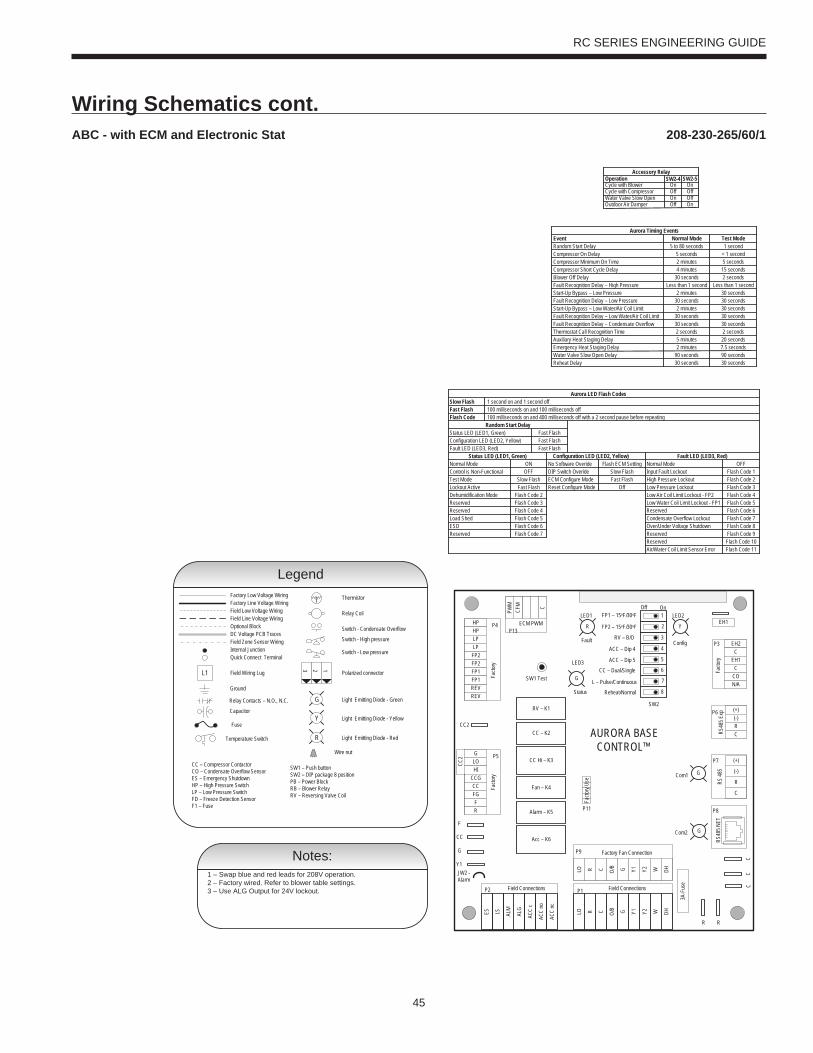
45
RC SERIES ENGINEERING GUIDE
Wiring Schematics cont.208-230-265/60/1ABC - with ECM and Electronic Stat
CC2
EH1
Facto
ry
Fault
ALG
ALMLSES ACC
c
Status
AURORA BASE CONTROL™
RV – K1
CC2
CC – K2
CC Hi – K3
Fan – K4
Alarm – K5
Acc – K6
ACC
no
ACC
nc
O/BCRLO G Y1 Y2 W DH
3A-F
use
O/BCRLO G Y1 Y2 W DH
LOG
HICCGCCFGFR
HPHPLP
FP2FP2FP1
REVREV
CFM
PWM
ECM PWM
Facto
ry
Factory Fan Connection
R R
CC
C
C
R
(-)
(+)
RS 48
5
EH2C
EH1C
CO
(+)(-)RCRS
485 E
xpFa
ctory
Com1
Com2
Config
G
G
G
YR
SW1 Test
FP1 – 15oF/30oF
JW2 - Alarm
P11
P5
P2 P1
P8
P7
P9
P6
P3
SW2
P13P4 FP2 – 15oF/30oF
RV – B/O
ACC – Dip 4
ACC – Dip 5
CC – Dual/Single
L – Pulse/Continuous
Reheat/Normal
Facto
ry Us
e
Field ConnectionsField Connections
C
LP
FP1
F
CC
G
Y1
1
2
3
4
5
6
7
8
Off On
N/A
RS48
5 NET
LED3
LED2LED1
Notes:1 – Swap blue and red leads for 208V operation.2 – Factory wired. Refer to blower table settings.3 – Use ALG Output for 24V lockout.
Wire nut
Temperature Switch
Thermistor
Relay Coil
Switch - Condensate Overflow
Switch - High pressure
Switch - Low pressure
Polarized connector
Factory Low Voltage WiringFactory Line Voltage WiringField Low Voltage WiringField Line Voltage WiringOptional BlockDC Voltage PCB Traces
Internal JunctionQuick Connect Terminal
Field Wiring Lug
Ground
Relay Contacts – N.O., N.C.
Field Zone Sensor Wiring
Legend
L1
Capacitor
T
123
CC – Compressor Contactor CO – Condensate Overflow SensorES – Emergency ShutdownHP – High Pressure SwitchLP – Low Pressure Switch FD – Freeze Detection Sensor F1 – Fuse
Fuse
Light Emitting Diode - GreenG
Light Emitting Diode - YellowY
Light Emitting Diode - RedR
SW1 – Push buttonSW2 – DIP package 8 positionPB – Power BlockRB – Blower RelayRV – Reversing Valve Coil
Slow FlashFast FlashFlash Code
Status LED (LED1, Green)Configuration LED (LED2, Yellow)Fault LED (LED3, Red)
Status LED (LED1, Green)Normal ModeControl is Non-FunctionalTest ModeLockout ActiveDehumidification ModeReservedReservedLoad ShedESD
1 second on and 1 second off
Random Start DelayFast Flash
OFFON
Slow FlashFast Flash
Flash Code 2Flash Code 3
Flash Code 6
Flash Code 4Flash Code 5
Aurora LED Flash Codes
100 milliseconds on and 100 milliseconds off100 milliseconds on and 400 milliseconds off with a 2 second pause before repeating
Reserved Flash Code 7
Configuration LED (LED2, Yellow) Fault LED (LED3, Red)
Fast FlashFast Flash
No Software Overide Flash ECM SettingDIP Switch Overide Slow Flash
Normal ModeInput Fault LockoutHigh Pressure LockoutLow Pressure Lockout
Low Water Coil Limit Lockout - FP1Low Air Coil Limit Lockout - FP2
ReservedCondensate Overflow LockoutOver/Under Voltage ShutdownReservedReservedAir/Water Coil Limit Sensor Error
Flash Code 1OFF
Flash Code 2Flash Code 3Flash Code 4Flash Code 5
Flash Code 8
Flash Code 6Flash Code 7
Flash Code 9Flash Code 10Flash Code 11
ECM Configure Mode Fast FlashReset Configure Mode Off
Accessory Relay
Cycle with BlowerCycle with CompressorWater Valve Slow OpenOutdoor Air Damper
SW2-4 SW2-5On OnOff OffOn OffOff On
Operation
Event Normal Mode Test ModeRandom Start DelayCompressor On DelayCompressor Minimum On TimeCompressor Short Cycle DelayBlower Off DelayFault Recognition Delay – High PressureStart-Up Bypass – Low PressureFault Recognition Delay – Low PressureStart-Up Bypass – Low Water/Air Coil LimitFault Recognition Delay – Low Water/Air Coil LimitFault Recognition Delay – Condensate OverflowThermostat Call Recognition TimeAuxiliary Heat Staging DelayEmergency Heat Staging Delay
Less than 1 second
5 to 80 seconds 1 second5 seconds < 1 second
30 seconds 2 secondsLess than 1 second
2 minutes 5 seconds4 minutes 15 seconds
2 minutes
2 minutes
30 seconds30 seconds 30 seconds
30 seconds30 seconds
30 seconds30 seconds30 seconds
2 seconds 2 seconds5 minutes2 minutes
20 seconds7.5 seconds
Aurora Timing Events
Reheat Delay 30 seconds 30 secondsWater Valve Slow Open Delay 90 seconds 90 seconds
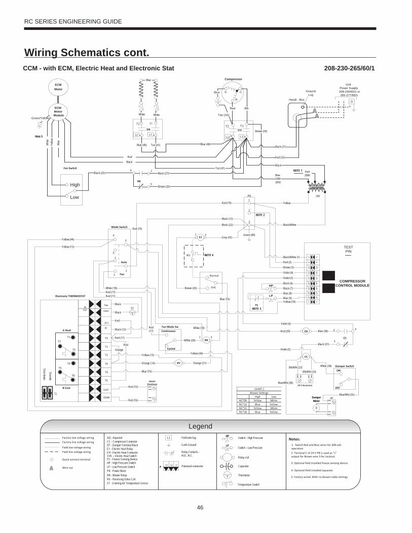
46
RC SERIES ENGINEERING GUIDE
Wiring Schematics cont.CCM - with ECM, Electric Heat and Electronic Stat 208-230-265/60/1
24V
Transformer
EH
CC
Legend
LP
HP
UnitPower Supply208-230/60/1 or265-277/60/1
GHandi - Box
GroundLug
Cycled
Continuous
CCT2 T1
Compressor
C
R
S
Tan (33)
Red Blk
Blue
L1L2
High
Low
Auto
Fan
6
1
32
4
5
COMPRESSORCONTROL MODULE
TESTPIN
HP
HP
CCCG
LOR
CLP
LPY
HP
HP
CCCG
LOR
CLP
LPY
Blue230V265V
Red208V
Black
Yellow
Black/White
Black/White (1)Red (2)
Black (6)Black (7)Blue (8)Blue (9)
Ther
mistor
Electronic THERMOSTAT
T1
T3
B Cool
A Heat
T2
T4
T6
T5
SHUT
DOWN
24 V
AC
INPUT
T6
T4T5
T2T1
T3
Overide
Shut down
J1
Red
Violet (5)
Yellow (13)
Yellow (10)
White (20)
Orange (14) Orange (21)
Orange
Black (12)
White (18)
Red (11)
Red (19)
Red (17)
24 V Accessory
24VACShutdown
Red (15)
Red (16)
NOTE 1
T
STBlack
Black
Red (11)
Black (12)
Red (17)
Red (19)
Black (25)
Black (31)
Red (32)
Brown (26)
Black (27)
RB
4 2
5
Red
EH
T2 T1
L2
WhiteWhite
L1
EHS
Normal
RV
DT
ON
OFF
Damper Switch
Damper Motor
D
Fan Mode Sw4
5
2
E1
E1
AQ
Blk/Wht (24)Blk/Wht (23)
Black (22)
White (18)
Blue (T6)
NOTE 2
31RB
31
Black (37)
Blue (38)
Blue/Wht (36)
Blue/Wht (35)
White (34)
Blue (T6)
FS
Yellow (44)
Yellow (44)
Brown (43)
Yellow (13)
Page 1
Blue
Tan (41)Blue (40) Blue (40)
Brown (3)
Tan (41)
Brown (26)
Green (00)
Red (39)
Gray (42)
NOTE 3
NOTE 4
Violet (4)
Violet (4)
Violet (5)
Factory low voltage wiring
Temperature Switch
Factory line voltage wiring
Quick connect terminal
Wire nut
Notes:1. Switch Red and Blue wires for 208 volt operationField low voltage wiring
Field line voltage wiring
CC - Compressor Contactor
HP - High Pressure SwitchLP - Low Pressure Switch
RV - Reversing Valve CoilST - Entering Air Temperature Sensor
RB - Blower Relay
2. Terminal C of 24 V PB is used as “L”output for Brown wire 3 for Lockout.
Legend
DT - Damper Terminal Block
PB - Power Block
Field wire lug
Earth Ground
Relay Contacts -N.O., N.C.
Polarized connector
132
P
Switch - High Pressure
Switch - Low Pressure
Relay coil
Capacitor
Thermistor
HP
LP
T
L1
3. Optional field installed freeze sensing device. FS - Freeze Sensing Device
4. Optional field installed aquastat.
AQ - Aquastat
EH - Electric Heat ContactorE1 - Electric Heat Relay
PB1
2
3Mode Switch
Fan Switch
EHS – Electric Heat Switch
Note 5
ECMMotor
Green/Yellow
ECMMotorModule
Blue
Yello
wW
hite
5. Factory wired. Refer to blower table settings.
RedBlack
High LowNC*09 Yellow WhiteNC*12 Blue YellowNC*15 Yellow WhiteNC*18 Blue Yellow
Blower Se ngsCHART 1

47
RC SERIES ENGINEERING GUIDE
GeneralFurnish and install Water Source Heat Pumps, as indicated on the plans. Equipment shall be completely assembled, piped and internally wired. Chassis shall be installed with factory built cabinet or other approved custom cabinet. Chassis SHALL NOT be installed without an approved cabinet enclosure. Capacities and characteristics as listed in the schedule and the specifications that follow. The reverse cycle heating/cooling units shall be floor mounted console type with horizontal air inlet and up-fl ow air discharge. Units shall be AHRI/ISO 13256-1 certifi ed and listed by a nationally recognized safety-testing laboratory or agency, such as ETL Testing Laboratory. Each unit shall be computer run-tested at the factory with conditioned water and operation verifi ed to catalog data. Each unit shall be mounted on a pallet and shipped in a corrugated box or stretch-wrapped. The units shall be designed to operate with entering liquid temperature between 20°F and 120°F [-6.7°C and 48.9°C].
Chassis and CabinetThe cabinet shall be fabricated from heavy-gauge galvanized steel and finished with a beige textured epoxy powder coating on both sides for added protection. This corrosion protection system shall meet the stringent 1000 hour salt spray test per ASTM B117.
The cabinet shall be easily removable to allow for ease of service to the controls compartment, chassis, and piping. The top of the cabinet and grille is a horizontally flat (optional sloped) surface with a hinged control door cover. The return air filter shall be 1” (25.4 mm) fiberglass disposable type media.
The return and supply air sections are insulated with a 1/4” (6.4 mm) thick, dual density, 2 lb/ft3 (32 kg/m3) coated mat glass fiber with edges sealed or tucked under flanges to prevent the introduction of glass fibers into the discharge supply air through the aluminum grille. Standard cabinet panel insulation must meet NFPA 90A requirements, air erosion and mold growth limits of UL-181, stringent fungal resistance test per ASTM-C1071 and ASTM G21, and shall meet zero level bacteria growth per ASTM G22. Unit insulation must meet these stringent requirements or unit(s) will not be accepted.
Option: A Super Quiet Sound package shall include multi-density full coverage compressor blanket.
Option: Shipped with motorized outside air damper and damper assembly for 25% make-up air.
The drain pan shall be of stainless steel construction to inhibit corrosion and bacterial growth. Drain outlet shall be located on pan as to allow complete and unobstructed drainage of condensate. The unit as standard will be supplied with solid-state electronic condensate overflow protection with Aurora Base Control. Mechanical float switches WILL NOT be accepted. Condensate tube shall be constructed of stainless steel and have an internal factory installed condensate trap.
Refrigerant CircuitAll units shall utilize the non-ozone depleting and low global warming potential refrigerant R410A. All units shall contain a sealed refrigerant circuit including a hermetic motor-compressor, bi-directional thermostatic expansion valve, finned tube air-to-refrigerant heat exchanger, reversing valve, coaxial tube water-to-refrigerant heat exchanger, and service ports.
Compressors shall be high-efficiency single speed rotary type designed for heat pump duty and mounted on durometer grommets to provide vibration free compressor mounting. Compressor motors shall be single-phase PSC with internal overload protection.
The air coil shall be sized for low-face velocity and constructed of lanced aluminum fins bonded to rifled aluminum tubes in a staggered pattern not less than three rows deep for enhanced performance.
Option: AlumiSeal electro-coated air coil.
The coaxial water-to-refrigerant heat exchanger shall be designed for low water pressure drop and constructed of a convoluted copper (cupronickel option) inner tube and a steel outer tube. Refrigerant to air heat exchangers shall utilize enhanced corrugated lanced aluminum fins and rifled aluminum tube construction rated to withstand 600 psig (4135 kPa) refrigerant working pressure. Refrigerant-to-water heat exchangers shall be of copper inner water tube and steel refrigerant outer tube design, rated to withstand 600 psig (4135 kPa) working refrigerant pressure and 450 psig (3101 kPa) working water pressure. The thermostatic expansion valve shall provide proper superheat over the entire liquid temperature range with minimal “hunting.” The valve shall operate bi-directionally without the use of check valves.
Option: Cupro-nickel refrigerant to water heat exchanger shall be of copper-nickel inner water tube and steel refrigerant outer tube design, rated to withstand 600 PSIG (4135 kPa) working refrigerant pressure and 450 PSIG (3101 kPa) working water pressure. Water lines shall also be of cupronickel construction.
Option: ThermaShield coated water-to-refrigerant heat exchanger, water lines and refrigerant suction lines shall be insulated to prevent condensation at low liquid temperatures below 50°F.
Fan Motor and AssemblyThe blower shall be a direct drive centrifugal type with a dynamically balanced wheel. The housing and wheel shall be designed for quiet, low outlet velocity operation. The blower housing shall be constructed of galvanized steel and shall be removable from the unit for servicing of the blower motor. The blower motor shall be a two-speed PSC or three-speed ECM type and shall be isolated from the housing by rubber grommets. The motor shall be permanently lubricated and have thermal overload protection.
ElectricalA control box shall be located within the unit compressor compartment and shall contain a 75VA transformer, 24 Volt activated, 2 pole compressor contactor, and solid-state controller for complete unit operation. Units shall be name-plated for use with time delay fuses or HACR circuit breakers. Unit controls shall be 24 Volt and provide heating or cooling as required by the remote thermostat/sensor.
Unit mounted controls shall consist of switches for “OFF”, “FAN”, and “AUTO” or “HEAT/COOL”. An additional switch is provided for fan speed setting of “HI” or “LO”. The unit shall be equipped with a fan switch on the side of the control to provide “CONTINUOUS” or “CYCLED” fan operation. “CYCLED” fan will turn the fan on with the compressor. A unit-mounted electronic thermostat with a remote electronic thermistor located in the return air will control compressor operation in heating and cooling modes.
Engineering Guide Specifi cations
48
RC SERIES ENGINEERING GUIDE
Unit mounted thermostat shall be the standard thermostat option. All unit mounted thermostats shall be auto changeover. Manual changeover WILL NOT be accepted. Electromechanical operation WILL NOT be accepted.
ControlsStandard: A compressor control module (CCM) shall be included to disable compressor operation in the event of a trip of any of the safety switches and to send a signal to activate a fault indicator light at the thermostat. The CCM shall be capable of being reset from the thermostat or from the unit main disconnect switch. A terminal block with screw terminals shall be provided for field connection of all low-voltage wiring.
An Aurora microprocessor-based controller that interfaces with a multi-stage electronic thermostat to monitor and control unit operation shall be provided. The control shall provide operational sequencing, blower speed control, high and low pressure switch monitoring, freeze detection, condensate overflow sensing, lockout mode control, LED status and fault indicators, fault memory, field selectable options and accessory output. The control shall provide fault retry three times before locking out to limit nuisance trips. A detachable terminal block with screw terminals will be provided for field control wiring. All units shall have knockouts for entrance of low and line voltage wiring. The blower motor and control box shall be harness plug wired for easy removal.
Option: Remote mounted thermostat is available for CCM and Aurora Base Control. A terminal block with screw terminals will be provided for field control wiring. PipingSupply and return water connections shall be 1/2 in. [12.7 mm] FPT copper threaded fittings. All water piping shall be insulated to prevent condensation at low liquid temperatures.
A stainless steel tube stubbed out from the chassis is provided for condensate drain attachment. A short piece of polyvinyl hose is supplied to assist in adapting to drain.
AccessoriesHose Kits – Ball Valves (field-installed)A flexible steel braid hose featuring Kevlar® reinforced EPDM core with ANSI 302/304 stainless steel outer braid and fire rated materials per ASTM E 84-00 (NFPA 255, ANSI/UL 723 & UBC 8-1). Ball valve at one end; swivel connector with adapter at the other end (swivel to adapter connection via fiber or EPDM gasket). Swivel connection provides union between heat pump and piping system. The hoses feature brass fittings, stainless steel ferrules. A full port ball valve shall be provided with integral P/T (pressure/temperature) port on supply hose. Specifi cations: Temperature range of 35°F [2°C] to 180°F [82°C]. Max. working pressure of 400 psi [2757 kPa] for 1/2˝ and 3/4˝ hose kits; max. working pressure of 350 psi [kPa] for 1˝ and 1-1/4˝ hose kits.
Hose Kits - Automatic Balancing and Ball Valves (field-installed)A flexible steel braid hose featuring Kevlar® reinforced EPDM core with ANSI 302/304 stainless steel outer braid and fire rated materials per ASTM E 84-00 (NFPA 255, ANSI/UL 723 & UBC 8-1). Ball valve at one end; swivel connector with adapter at the other end (swivel to adapter connection via fiber or EPDM gasket). Swivel connection provides union between heat pump and piping system. The hoses feature brass fittings, stainless steel ferrules. A full port ball valve shall be provided with integral P/T (pressure/temperature) port on supply hose and automatic balancing valve with integral P/T ports and full port ball valve on return hose.
Specifi cations:• Temperature range of 35°F [2°C] to 180°F [82°C].• Max. working pressure of 400 psi [2757 kPa] for 1/2˝ and 3/4˝ hose kits; max. working pressure of 350 psi [2413 kPa] for 1˝ and 1-1/4˝ hose kits. • Minimum burst pressure of four times working pressure.
Hose Kits – Automatic Balancing and Ball Valves with ‘Y’ strainer (field-installed)A flexible steel braid hose featuring Kevlar® reinforced EPDM core with ANSI 302/304 stainless steel outer braid and fire rated materials per ASTM E 84-00 (NFPA 255, ANSI/UL 723 & UBC 8-1). Ball valve at one end; swivel connector with adapter at the other end (swivel to adapter connection via fiber or EPDM gasket). Swivel connection provides union between heat pump and piping system. The hoses feature brass fittings, stainless steel ferrules. A “y” strainer is provided on one end for fluid straining and integral “blowdown” valve.. A full port ball valve shall be provided with integral P/T (pressure/temperature) port on supply hose and automatic balancing valve with integral P/T ports and full port ball valve on return hose.
Specifi cations:• Temperature range of 35°F [2°C] to 180°F [82°C].• Max. working pressure of 400 psi [2757 kPa] for 1/2˝ and 3/4˝ hose kits; max. working pressure of 350 psi [2413 kPa] for 1˝ and 1-1/4˝ hose kits. • Minimum burst pressure of four times working pressure.
Auxiliary Heater (field-installed 208-230V units only)An electric resistance heater shall provide supplemental and/or emergency heating capability. A manual switch shall be mounted on the side of the control compartment with “NORMAL” or “BOILERLESS” mode. “NORMAL” will run the compressor when there is a call for heating or cooling. “BOILERLESS” mode operation will run electric heat whenever there is a call for heating and run the compressor for a cooling call.
Engineering Guide Specifi cations cont.

49
RC SERIES ENGINEERING GUIDE
Notes


51
RC SERIES ENGINEERING GUIDE
Revision GuidePages: Description: Date: By:Multiple Removed FX10 Control Option, Added Aurora Controls, Updated Wiring Schematics 01 Mar 2017 MA
All Obsoleted PSC Option, Updated Nomenclature, Updated Wiring Schematics 04 Mar 2015 MA
All Updated with All-Aluminum Air Coils 07 Mar 2014 DS
49 Added Revision Table 07 Mar 2014 DS

Product: RC Series ConsoleType: Geothermal/Water Source Heat PumpSize: 0.75-1.5 Ton
Document Type: Engineering GuideForm: 146.04-EG1 (0317)Supercedes: 146.00-EG4 (0515)