geotechnical engineering report - savannah,...
TRANSCRIPT

Geotechnical Engineering Report City of Savannah 63rd Street Relief Line
Savannah, Georgia
April 19, 2011
Terracon Project No. ES115039
Prepared for:
EMC Engineering Services, Inc.
Savannah, Georgia
Prepared by:
Terracon Consultants, Inc.
Savannah, Georgia

Terracon Consultants, Inc. 2201 Rowland Avenue Savannah GA 31404
P [912] 629-4000 F [912] 629-4001 terracon.com
April 19, 2011
EMC Engineering Services, Inc.
23 E. Charlton Street
Savannah, Georgia 31401
Attn: Mr. Ben Lockhart, P.E.
P: [912] 232-6533
Re: Geotechnical Engineering Report
City of Savannah 63rd Street Relief Line
Savannah, Georgia
Terracon Project No: ES115039
Dear Mr. Lockhart:
Terracon Consultants, Inc. (Terracon) has completed the geotechnical engineering services for
the above-referenced project. The service was performed in general accordance with our
proposal No.PES110163. This report presents the findings of the subsurface exploration and
provides geotechnical recommendations concerning earthwork, design and construction of the
proposed project.
We appreciate the opportunity to be of service to you on this project. If you have any questions
concerning this report, or if we may be of further service, please contact us.
Sincerely,
Terracon Consultants, Inc.
Zengxuan (Frank) Li, Ph.D., P.E. Guoming Lin, Ph.D., P.E.
Senior Engineer Senior Principal
Enclosures
cc: 1 – Client (PDF)
1 – File

Reliable ■ Responsive ■ Convenient ■ Innovative
TABLE OF CONTENTS
Page
EXECUTIVE SUMMARY ............................................................................................................. i
1.0 INTRODUCTION ............................................................................................................. 1
2.0 PROJECT INFORMATION ............................................................................................. 1
2.1 Project Description ............................................................................................... 1
2.2 Site Location and Description .............................................................................. 2
3.0 SUBSURFACE CONDITIONS ........................................................................................ 2
3.1 Typical Profile ...................................................................................................... 2
3.2 Groundwater ........................................................................................................ 4
4.0 RECOMMENDATIONS FOR DESIGN AND CONSTRUCTION ...................................... 4
4.1 Recommendations on Box Culvert Support ........................................................... 4
4.2 Recommendations on Sheet Pile Design and Construction ................................... 5
4.2.1 Recommendations on Sheet Pile Design.................................................. 5
4.2.2 Construction Considerations..................................................................... 6
4.3 Seismic Design Parameters .................................................................................. 8
5.0 GENERAL COMMENTS ................................................................................................. 8
APPENDIX A – FIELD EXPLORATION
Exhibit A-1 Site Location Map
Exhibit A-2 Exploration Location Plan
Exhibit A-3 CPT Sounding Cross Section
Exhibit A-4 CPT Sounding Logs
Exhibit A-5 SPT Boring Cross Section
Exhibit A-6 SPT Boring Logs
Exhibit A-7 Hand Auger Boring Logs
Exhibit A-8 Field Exploration Description
APPENDIX B – SUPPORTING INFORMATION
Exhibit B-1 Laboratory Testing
Exhibit B-2 Seismic Design Parameters
Exhibit B-3 General Notes
Exhibit B-4 Unified Soil Classification System

Geotechnical Engineering Report City of Savannah 63rd Street Relief Line ■ Savannah, Georgia April 19, 2011 ■ Terracon Project No. ES115039
Reliable ■ Responsive ■ Convenient ■ Innovative i
EXECUTIVE SUMMARY
A geotechnical investigation has been performed for the proposed City of Savannah 63rd Street
Relief Line in Savannah, Georgia. The field exploration program consisted of seven (7) cone
penetration test (CPT) soundings to a maximum depth of 56 feet below the existing ground surface
(BGS), five (5) standard penetration test (SPT) borings to a maximum depth of 55 feet BGS and
twelve (12) hand auger borings to a depth of 6 feet BGS. The following geotechnical
considerations were identified:
Subsurface conditions along the project alignment are relatively variable. Three
generalized profiles of soil strata are identified, which represent subsurface soil
conditions at different exploration locations.
Based on the encountered soil conditions, three sets of soil parameters are
recommended for sheet pile design, corresponding to the three generalized profiles.
For seismic design, the site shall be classified as Site Class D in accordance with the
International Building Code (IBC) 2006, Section 1613.
This summary should be used in conjunction with the entire report for design purposes. It
should be recognized that details were not included or fully developed in this section, and the
report must be read in its entirety for a comprehensive understanding of the items contained
herein. The section titled GENERAL COMMENTS should be read for an understanding of the
report limitations.

Reliable ■ Responsive ■ Convenient ■ Innovative 1
GEOTECHNICAL ENGINEERING REPORT
CITY OF SAVANNAH 63RD STREET RELIEF LINE
SAVANNAH, GEORGIA Terracon Project No. ES115039
April 19, 2011
1.0 INTRODUCTION
A geotechnical engineering report has been completed for the proposed City of Savannah 63rd
Street Relief Line in Savannah, Georgia. The field exploration program consisted of seven (7) cone
penetration test (CPT) soundings to a maximum depth of 56 feet below the existing ground surface
(BGS), five (5) standard penetration test (SPT) borings to a maximum depth of 55 feet BGS and
twelve (12) hand auger borings to a depth of 6 feet BGS. CPT sounding logs, SPT boring logs and
hand auger boring logs, along with a site location map and exploration location plan are included in
Appendix A of this report.
The purpose of this study is to provide subsurface information and geotechnical engineering
recommendations relative to:
subsurface soil conditions foundation design and construction
groundwater conditions seismic considerations
2.0 PROJECT INFORMATION
2.1 Project Description
ITEM DESCRIPTION
Proposed Improvement
A new drainage system includes junction boxes, box culverts and cast-in-place concrete and asphalt pavements. The installation of the drainage system will require excavation to depths on the order of 20 feet deep and the potential installation and removal of sheet piles or other methods as temporary shoring to support the excavation.
Finished floor elevation Not applicable.
Maximum loads Not applicable.
Maximum allowable settlement Not provided. We assume one inch of total settlement and 0.5
inches of differential settlement between joints.
Grading (Cut or Fill) Excavation to an approximate depth of 20 feet below grade and
backfill to existing grade.

Geotechnical Engineering Report City of Savannah 63rd Street Relief Line ■ Savannah, Georgia April 19, 2011 ■ Terracon Project No. ES115039
Reliable ■ Responsive ■ Convenient ■ Innovative 2
2.2 Site Location and Description
ITEM DESCRIPTION
Location
The site is located along Abercorn Street to 63rd
Street to 60th
Street in Savannah, Georgia.
Latitude: 32.0333°, Longitude: -81.0975°
Existing improvements
The alignment has existing stormwater drainage piping and paved
roadways. There are various residential structures along the
alignment.
Current ground cover Asphalt and concrete roadways.
Existing topography Elevations vary along the alignment. No survey work was
performed for this geotechnical investigation.
3.0 SUBSURFACE CONDITIONS
3.1 Typical Profile
Based on the results of the field exploration, subsurface conditions along the project alignment are
relatively variable. We have generated three generalized profiles, designated as profile I through
profile III, which represent subsurface conditions along different reaches of the alignment.
Profile I representing the subsurface soil conditions from C-1 to B-4
Description Approximate Elevation of
Bottom of Stratum (feet) Material Encountered
SPT Blow Count
and/or N60 Derived
from CPT Sounding
Stratum 1 1 to 4 Soft sandy clay, with interbedded
thin sand layers 2 to 4
Stratum 2 -19 to -21
Medium dense to dense silty
sands, with interbedded clay
layers
10 to 45
Stratum 3 -28 Stiff sandy clay 12 to 17
Stratum 4
Undetermined. Explorations
were terminated within this
stratum
Dense silty sand 30 to 40

Geotechnical Engineering Report City of Savannah 63rd Street Relief Line ■ Savannah, Georgia April 19, 2011 ■ Terracon Project No. ES115039
Reliable ■ Responsive ■ Convenient ■ Innovative 3
Description Approximate Elevation of
Bottom of Stratum (feet) Material Encountered
SPT Blow Count
and/or N60 Derived
from CPT Sounding
Note:
Elevation survey was not performed as part of this geotechnical exploration. The surface elevations were
extrapolated from the elevations in the geotechnical engineering report prepared by ECS Ltd for EMC
Engineering Services, inc., dated April 27, 2001. The elevations should be considered approximate.
Profile II representing the subsurface soil conditions from C-2, C-3 to B-6.
Description Approximate Elevation of
Bottom of Stratum (feet) Material Encountered
SPT Blow Count
and/or N60 Derived
from CPT Sounding
Stratum 1 -1 to 3 Medium dense silty sand, with
interbedded thin clay layer 10 to 30
Stratum 2 -6 to -1 Medium stiff sandy clay, with
interbedded sand layer 5 to 7
Stratum 3
Undetermined. Explorations
were terminated within this
stratum
Medium dense to dense silty
sand, with interbedded thin clay
layer
10 to 40
Note:
Elevation survey was not performed as part of this geotechnical exploration. The surface elevations were
extrapolated from the elevations in the geotechnical engineering report prepared by ECS Ltd for EMC
Engineering Services, inc., dated April 27, 2001. The elevations should be considered approximate.
Profile III representing the subsurface soil conditions from C-5, C-7, C-9, C-11, B-8, B-10 and B-12.
Description Approximate Elevation of
Bottom of Stratum (feet) Material Encountered
SPT Blow Count
and/or N60 Derived
from CPT Sounding
Stratum 1 1 to 13 Medium dense silty sand, with
interbedded thin clay layer 13 to 33
Stratum 2 -4 to 8 Soft sandy clay 1 to 3
Stratum 3 -13 to 3 Loose to medium dense silty
sand, with interbedded clay layer 7 to 33
Stratum 4 -36 to -22 Soft to stiff sandy clay, with
interbedded sand layer 2 to 14
Stratum 5
Undetermined. Explorations
were terminated within this
stratum.
Medium dense to dense silty
sand 11 to 37

Geotechnical Engineering Report City of Savannah 63rd Street Relief Line ■ Savannah, Georgia April 19, 2011 ■ Terracon Project No. ES115039
Reliable ■ Responsive ■ Convenient ■ Innovative 4
Description Approximate Elevation of
Bottom of Stratum (feet) Material Encountered
SPT Blow Count
and/or N60 Derived
from CPT Sounding
Note:
Elevation survey was not performed as part of this geotechnical exploration. The surface elevations were
extrapolated from the elevations in the geotechnical engineering report prepared by ECS Ltd for EMC
Engineering Services, inc., dated April 27, 2001. The elevations should be considered approximate.
Details of subsurface conditions encountered at each exploration location are presented on the
individual exploration logs in Appendix A of this report. Stratification boundaries on the logs
represent the approximate depth of changes in soil types; and the transition between materials
may be gradual.
3.2 Groundwater
Groundwater was encountered at depths of 4 to 6 feet below existing ground surface during SPT
borings. It should be noted that groundwater levels tend to fluctuate with seasonal and climatic
variations, as well as with construction activities. As such, the possibility of groundwater level
fluctuations should be considered when developing the design and construction plans for the
project. The groundwater table should be checked prior to construction to assess its effect on site
work and other construction activities.
4.0 RECOMMENDATIONS FOR DESIGN AND CONSTRUCTION
The following evaluation and recommendations are based upon our understanding of the
proposed construction and the results of the field exploration. If the above-described project
conditions are incorrect or changed after this report, or subsurface conditions encountered
during construction are different from those reported, Terracon should be notified and these
recommendations must be re-evaluated to make appropriate revisions.
4.1 Recommendations on Drainage Structure Support
Excavation required for the installation of box culverts and junction boxes will remove
overburden soils. In general, the weight of soil to be removed should be greater than the weight
of box culverts or junction boxes resulting in a reduction of stresses within the subgrade soil
below the drainage structures. Strictly speaking, the box culverts and junction boxes should not
cause consolation settlements in addition to re-compaction of subgrade soil which should be
small and tolerable. However, as shown in the soil boring and CPT sounding profiles, the soils
along the alignment are variable. Depending on the depth of excavation, the subgrade soils
may be soft clays that are not suitable for subgrade support or in unstable condition. Placement

Geotechnical Engineering Report City of Savannah 63rd Street Relief Line ■ Savannah, Georgia April 19, 2011 ■ Terracon Project No. ES115039
Reliable ■ Responsive ■ Convenient ■ Innovative 5
of concrete structures on unstable subgrade can result in movements or settlements of the
structures. It is important that the subgrade along the entire alignment be inspected and tested
during construction. Unsuitable or unstable subgrade, if encountered, should be repaired in
accordance with the following procedures.
After excavating to the required subgrade elevation, a technician should inspect the
bottom of the excavation for soil suitability and stability. The technician should perform
hand auger borings with dynamic penetrometer tests to a depth of at least 5 ft below the
subgrade to verify the soil conditions and bearing capacity.
If unsuitable materials such as organic soils or soft clays are encountered during
subgrade inspection, they must be undercut and replaced with suitable structural fill or
graded aggregates. If subgrade soils are unstable due to excessive moisture content,
the unstable soils should be excavated and re-compacted under favorable weather
conditions or replaced with graded aggregates. The depth and extent of the undercut
should be determined on-site by a Geotechnical Engineer based on the conditions of the
weak material.
We recommend all box culverts and junction boxes be placed over a bedding layer consisting of
12 inches of #57 stone over a layer of filter fabric. The #57 stone should help dewatering effort
to allow water to run through. The filter fabric is intended to control migration of fine sands into
the voids within the #57 stone. A net bearing capacity of 1500 pounds per square foot is
recommended for the box culvert design.
4.2 Recommendations on Excavation Shoring Design and Construction
4.2.1 Recommendations on Excavation Shoring Design
Based on the soil conditions encountered, we recommend the following soil parameters be used
for the excavation shoring design. Three tables with recommended soil parameters are
included, corresponding to the three typical profiles in section 3.1. Any surcharge or additional
load behind the sheet pile should be considered in the design.
Recommended Soil Parameters for Profile I
Bottom
Elevation
(ft)
Material Description T.U.W. E.U.W. Fi C Ko Ka Kp
(pcf) (pcf) (psf)
3 Soft sandy clay 115 50 0 400 1 1 1
-21 Medium dense to dense silty
sand 125 60 33 0 0.46 0.29 3.39
-28 Stiff sandy clay 120 55 0 2000 1 1 1
Undetermined Dense silty sand 125 60 33 0 0.46 0.29 3.39

Geotechnical Engineering Report City of Savannah 63rd Street Relief Line ■ Savannah, Georgia April 19, 2011 ■ Terracon Project No. ES115039
Reliable ■ Responsive ■ Convenient ■ Innovative 6
Note: E.U.W.: Total Unit Weight, pcf; Ko: Coefficient of At Rest Earth Pressure;
E.U.W.: Effective Unit Weight, pcf; Kp: Coefficient of Passive Earth Pressure;
Fi: Angle of Internal Friction, degree; Ka: Coefficient of Active Earth Pressure;
C: Cohesion, psf
Recommended Soil Parameters for Profile II
Bottom
Elevation
(ft)
Material Description T.U.W. E.U.W. Fi C Ko Ka Kp
(pcf) (pcf) (psf)
3 Medium dense silty sand 125 60 30 0 0.5 0.33 3.0
-21 Medium stiff sand clay 120 55 0 1000 1 1 1
Undetermined Medium dense silty sand 125 60 30 0 0.5 0.33 3.0
Note: E.U.W.: Total Unit Weight, pcf; Ko: Coefficient of At Rest Earth Pressure;
E.U.W.: Effective Unit Weight, pcf; Kp: Coefficient of Passive Earth Pressure;
Fi: Angle of Internal Friction, degree; Ka: Coefficient of Active Earth Pressure;
C: Cohesion, psf
Recommended Soil Parameters for Profile III
Bottom
Elevation
(ft)
Material Description T.U.W. E.U.W. Fi C Ko Ka Kp
(pcf) (pcf) (psf)
7 Medium dense, silty sand 125 60 30 0 0.5 0.33 3.0
2 Soft sandy clay 115 50 0 500 1 1 1
-5 Medium dense silty sand 125 60 30 0 0.5 0.33 3.0
-29 Medium stiff clay 120 55 0 1000 1 1 1
Undetermined Medium dense to dense sand 125 60 33 0 0.46 0.29 3.39
Note: E.U.W.: Total Unit Weight, pcf; Ko: Coefficient of At Rest Earth Pressure;
E.U.W.: Effective Unit Weight, pcf; Kp: Coefficient of Passive Earth Pressure;
Fi: Angle of Internal Friction, degree; Ka: Coefficient of Active Earth Pressure;
C: Cohesion, psf
4.2.2 Construction Considerations
Construction of the proposed relief line will require excavation to a maximum depth of
approximately 20 feet below existing grades. There are many residential houses located near
the proposed alignment. Based on the distance of the houses to the construction site and our
experience with similar projects, we recommend the owner of the project and the
design/construction team to take precautionary measures to avoid damage to the adjacent
structures to protect the property owners as well as the City and the design/construction team
against frivolous claims. The following precautionary measures are recommended based on our
experiences in similar projects.

Geotechnical Engineering Report City of Savannah 63rd Street Relief Line ■ Savannah, Georgia April 19, 2011 ■ Terracon Project No. ES115039
Reliable ■ Responsive ■ Convenient ■ Innovative 7
Communications We recommend that the City communicate with local communities,
especially adjacent residences, about the construction schedule, sequence and potential impact
to their properties from the proposed construction. The residences should be provided with a
point of contact to answer their questions and address their concerns.
Pre-construction condition survey We recommend a pre-construction survey be performed
for the structures located close to the construction site or potentially having the most significant
impact from the construction activities. The pre-construction survey should include
documentation of existing cracks and any other noticeable distresses on the structures.
Monitoring during construction Depending on the outcome of the condition survey and the
method of construction, the existing structures may be monitored during construction. The
monitoring may include recording the changes of existing cracks and ground vibration. We
recommend the pre-condition survey and monitoring be performed by the City and its
consultants, not by the contractor. Groundwater monitoring should be performed considering the
depth of dewatering. The consultant to be retained by the City should prepare plans for
monitoring based on the construction plan and results from the pre-condition survey.
Dewatering Groundwater was encountered at approximately 4 to 6 feet below the existing
ground surface. We anticipate dewatering will be needed for excavation. We recommend that
the groundwater be lowered to a depth of at least two feet below the bottom of the excavation.
The contractor should determine the method of dewatering. It is important to note that
extensive dewatering could cause a drop in groundwater level outside the sheet pile walls which
may have detrimental impact to the existing structures. If possible, we recommend that
dewatering be limited to inside the excavation. Furthermore, dewatering should be performed as
short duration as necessary. Monitoring of groundwater levels may be performed if extensive
dewatering is required where structures exist in the close proximity.
Potential Hard Installation Dense soils were encountered at several of the exploration
locations. The contractor should review the soil conditions and use proper equipment to install
the excavation support to the design tip elevations.
Backfill Placement All material to be used for backfill should be evaluated and tested by
Geotechnical Engineer to determine their suitability for backfill. In general, backfill material should
be granular materials containing less than 25% fines passing the No. 200 sieve. All backfills
should be placed in thin (eight to ten inches loose) lifts and compacted to a minimum of 95% of
the soil's modified proctor maximum dry density (ASTM D-1557). In most cases, the on-site
soils have moisture content above optimum value. Some manipulation of the moisture content
will be required during the filling operation to obtain the required degree of compaction. The
manipulation of the moisture content is highly dependent on weather conditions and site
drainage conditions. Therefore, the contractor should prepare both dry and wet fill materials to

Geotechnical Engineering Report City of Savannah 63rd Street Relief Line ■ Savannah, Georgia April 19, 2011 ■ Terracon Project No. ES115039
Reliable ■ Responsive ■ Convenient ■ Innovative 8
obtain the specified compaction during grading. Sufficient density tests should be performed to
confirm the required compaction of the fill material. Based on the findings of field exploration,
sandy soils classified as SP-SM, SM, and SC may be suitable backfill material, while the clayey
soils classified as CL or CH will not be acceptable backfill material.
4.3 Seismic Design Parameters
Based on the findings from the subsurface exploration and our knowledge of the local geological
formation in the project area, the site can be classified as Site Class D in accordance with IBC
2006. The seismic design parameters obtained based on IBC 2006 are summarized in table
below. The design response spectrum curve, as presented in the appendix, was developed
based on the SDS and SD1 values according to IBC 2006.
Summary of Seismic Design Parameters
Site Location
(Lat. – Long.)
Site
Classification Ss S1 Fa Fv SDS SD1
32.033312°
-81.097485° D 0.393g 0.120g 1.486 2.32 0.389g 0.186g
1. In general accordance with the 2006 International Building Code, Table 1613.5.2.
2. The 2006 International Building Code requires a site soil profile determination extending a depth of
100 feet for seismic site classification. The current scope does not include 100 foot soil profile
determination. Explorations for this project were extended to a maximum depth of 56 feet. The
seismic site class definition was provided in consideration of the overall soil conditions as well as the
general geology of the area.
5.0 GENERAL COMMENTS
Terracon should be retained to review the final design plans and specifications so comments
can be made regarding interpretation and implementation of our geotechnical recommendations
in the design and specifications. Terracon also should be retained to provide observation and
testing services during grading, excavation, foundation construction and other earth-related
construction phases of the project.
The analysis and recommendations presented in this report are based upon the data obtained
from the explorations performed at the indicated locations and from other information discussed
in this report. This report does not reflect variations that may occur between exploration
locations, across the site, or due to the modifying effects of construction or weather. The nature
and extent of such variations may not become evident until during or after construction. If
variations appear, we should be immediately notified so that further evaluation and
supplemental recommendations can be provided.

Geotechnical Engineering Report City of Savannah 63rd Street Relief Line ■ Savannah, Georgia April 19, 2011 ■ Terracon Project No. ES115039
Reliable ■ Responsive ■ Convenient ■ Innovative 9
The scope of services for this project does not include either specifically or by implication any
environmental or biological (e.g., mold, fungi, and bacteria) assessment of the site or
identification or prevention of pollutants, hazardous materials or conditions. If the owner is
concerned about the potential for such contamination or pollution, other studies should be
undertaken.
This report has been prepared for the exclusive use of our client for specific application to the
project discussed and has been prepared in accordance with generally accepted geotechnical
engineering practices. No warranties, either express or implied, are intended or made. Site
safety, excavation support, and dewatering requirements are the responsibility of others. In the
event that changes in the nature, design, or location of the project as outlined in this report are
planned, the conclusions and recommendations contained in this report shall not be considered
valid unless Terracon reviews the changes and either verifies or modifies the conclusions of this
report in writing.

APPENDIX A
FIELD EXPLORATION
Exhibit A-1 Site Location Map
Exhibit A-2 Exploration Location Plan
Exhibit A-3 CPT Sounding Cross Section
Exhibit A-4 CPT Sounding Logs
Exhibit A-5 SPT Borings Cross Section
Exhibit A-6 SPT Boring Logs
Exhibit A-7 Hand Auger Boring Records
Exhibit A-8 Field Exploration Description

SITE LOCATION MAP
CITY OF SAVANNAH 63RD ST RELIEF LINE
SAVANNAH, GEORGIAA-1
2201 Rowland Avenue Savannah, Georgia 31404
PH. (912) 629-4000 FAX. (912) 629-4001
ES115039
4/12/2011
ZL
WL
ZL
GL
N.T.S.
Project Manager:
Drawn by:
Checked by:
Approved by:
Project No.
Scale:
File Name:
Date:
Exhibit
APPROXIMATE
PROJECT ALIGNMENT

EXPLORATION LOCATION PLAN
CITY OF SAVANNAH 63RD ST RELIEF LINE
SAVANNAH, GEORGIAA-2
2201 Rowland Avenue Savannah, Georgia 31404
PH. (912) 629-4000 FAX. (912) 629-4001
ES115039
4/12/2011
ZL
WL
ZL
GL
N.T.S.
Project Manager:
Drawn by:
Checked by:
Approved by:
Project No.
Scale:
File Name:
Date:
Exhibit
THIS DIAGRAM IS FOR GENERAL
LOCATION ONLY, AND IS NOT INTENDED
FOR CONSTRUCTION PURPOSES
NOTES:
1. THIS EXPLORATION LOCATION PLAN WAS MODIFIED FROM THE SITE LAYOUT
PREPARED BY EMC ENGINEERING SERVICES, INC. TITLED “63rd STREET RELIEF
LINE DRAINAGE IMPROVEMENT”, DATED MARCH 2011 FOR CITY OF SAVANNAH.
2. ALL THE EXPLORATION LOCATIONS WERE LOCATED IN THE FIELD USING
STREET FEATURES, AND THE EXPLORATION LOCATIONS SHOULD BE
CONSIDERED APPROXIMATE.
LEGEND:
CPT
SPT
B-4
C-1
B-6
B-8
B-10B-12
C-2 C-3 C-5 C-7
C-9C-11

-40
-32
-24
-16
-8
0
8
16
24
32
-40
-32
-24
-16
-8
0
8
16
24
32
C1
0.00 feet
60.00 feet
C2
10.00 feet
50.00 feet
C3
20.00 feet
40.00 feet
C5
30.00 feet
30.00 feet
C7
40.00 feet
20.00 feet
C9
50.00 feet
10.00 feet
C11
60.00 feet
0.00 feet
[ feet]
0 80.00 160.00 240.00
0 80.00 160.00 240.00
0 80.00 160.00 240.00
0 80.00 160.00 240.00
0 80.00 160.00 240.00
0 80.00 160.00 240.00
0 80.00 160.00 240.00
qc
CPT SOUNDINGS CROSS SECTION
CITY OF SAVANNAH 63RD ST RELIEF LINE
SAVANNAH, GEORGIAA-3
2201 Rowland Avenue Savannah, Georgia 31404
PH. (912) 629-4000 FAX. (912) 629-4001
ES115039
4/9/2011
ZL
WL
ZL
GL
N.T.S.
Project Manager:
Drawn by:
Checked by:
Approved by:
Project No.
Scale:
File Name:
Date:
Exhibit
Ele
va
tion (f
t)
C-1 C-2qc (tsf) C-3 C-5 C-11C-7 C-9
NOTE:
ELEVATION SURVEY WAS NOT
PERFORMED AS PART OF THIS
GEOTECHNICAL EXPLORATION, THE
SURFACE ELEVATIONS WERE
EXTRAPOLATED FROM THE
ELEVATIONS IN THE GEOTECHNICAL
ENGINEERING REPORT PREPARED
BY ECS LTD FOR EMC ENGINEERING
SERVICES, INC., DATED APRIL 27,
2001. THE ELEVATIONS SHOULD BE
CONSIDERATED APPROXIMATE.
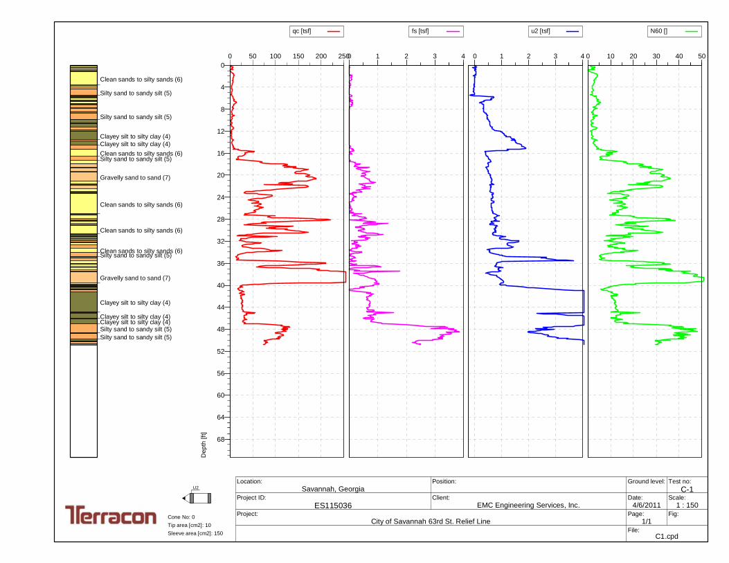
0 50 100 150 200 250
qc [tsf]
0
4
8
12
16
20
24
28
32
36
40
44
48
52
56
60
64
68
De
pth
[ft]
0 1 2 3 4
fs [tsf]
0 1 2 3 4
u2 [tsf]
0 10 20 30 40 50
N60 []
Test no:
C-1Project ID:
ES115036Client:
EMC Engineering Services, Inc.Project:
City of Savannah 63rd St. Relief Line
Position:Location:
Savannah, GeorgiaGround level:
Date:
4/6/2011Scale:
1 : 150Page:
1/1Fig:
File: C1.cpd
U2
Sleeve area [cm2]: 150
Tip area [cm2]: 10
Cone No: 0
Clean sands to silty sands (6)
Silty sand to sandy silt (5)
Silty sand to sandy silt (5)
Clayey silt to silty clay (4)
Clayey silt to silty clay (4)
Clean sands to silty sands (6)Silty sand to sandy silt (5)
Gravelly sand to sand (7)
Clean sands to silty sands (6)
Clean sands to silty sands (6)
Clean sands to silty sands (6)Silty sand to sandy silt (5)
Gravelly sand to sand (7)
Clayey silt to silty clay (4)
Clayey silt to silty clay (4)Clayey silt to silty clay (4)Silty sand to sandy silt (5)
Silty sand to sandy silt (5)

0 50 100 150 200 250
qc [tsf]
0
4
8
12
16
20
24
28
32
36
40
44
48
52
56
60
64
68
De
pth
[ft]
0 1 2 3 4
fs [tsf]
0 1 2 3 4
u2 [tsf]
0 10 20 30 40 50
N60 []
Test no:
C-2Project ID:
ES115039Client:
EMC Engineering Services, Inc.Project:
City of Savannah 63rd St. Relief Line
Position:Location:
Savannah, GeorgiaGround level:
Date:
4/6/2011Scale:
1 : 150Page:
1/1Fig:
File: C2.cpd
U2
Sleeve area [cm2]: 150
Tip area [cm2]: 10
Cone No: 0
Gravelly sand to sand (7)
Gravelly sand to sand (7)
Silty sand to sandy silt (5)
Clean sands to silty sands (6)Clean sands to silty sands (6)
Clean sands to silty sands (6)
Clean sands to silty sands (6)Clean sands to silty sands (6)
Clean sands to silty sands (6)
Clean sands to silty sands (6)
Clean sands to silty sands (6)
Clean sands to silty sands (6)Silty sand to sandy silt (5)
Clean sands to silty sands (6)

0 50 100 150 200 250
qc [tsf]
0
4
8
12
16
20
24
28
32
36
40
44
De
pth
[ft]
0 1 2 3 4
fs [tsf]
0 1 2 3 4
u2 [tsf]
0 10 20 30 40 50
N60 []
Test no:
C-3Project ID:
ES115039Client:
EMC Engineering Services, Inc.
Project:
City of Savannah 63rd St. Relief Line
Position:Location:
Savannah, GeorgiaGround level:
Date:
4/6/2011Scale:
1 : 100Page:
1/1Fig:
File: C3.cpd
U2
Sleeve area [cm2]: 150
Tip area [cm2]: 10
Cone No: 0
Gravelly sand to sand (7)
Gravelly sand to sand (7)
Clean sands to silty sands (6)
Clean sands to silty sands (6)
Gravelly sand to sand (7)
Gravelly sand to sand (7)
Clean sands to silty sands (6)
Clean sands to silty sands (6)
Clean sands to silty sands (6)
Clayey silt to silty clay (4)
Clayey silt to silty clay (4)
Clean sands to silty sands (6)
Clean sands to silty sands (6)
Clean sands to silty sands (6)
Silty sand to sandy silt (5)
Clean sands to silty sands (6)
Clean sands to silty sands (6)
Clean sands to silty sands (6)
Clean sands to silty sands (6)
Clean sands to silty sands (6)
Clean sands to silty sands (6)
Clean sands to silty sands (6)
Silty sand to sandy silt (5)
Clean sands to silty sands (6)
Clean sands to silty sands (6)

0 50 100 150 200 250
qc [tsf]
0
4
8
12
16
20
24
28
32
36
40
44
48
52
56
60
64
68
De
pth
[ft]
0 1 2 3 4
fs [tsf]
0 1 2 3 4
u2 [tsf]
0 10 20 30 40 50
N60 []
Test no:
C-5Project ID:
ES115039Client:
EMC Engineering Services, Inc.Project:
City of Savannah 63rd St. Relief Line
Position:Location:
Savannah, GeorgiaGround level:
Date:
4/6/2011Scale:
1 : 150Page:
1/1Fig:
File: C5.cpd
U2
Sleeve area [cm2]: 150
Tip area [cm2]: 10
Cone No: 0
Clean sands to silty sands (6)
Silty sand to sandy silt (5)
Clean sands to silty sands (6)
Clean sands to silty sands (6)
Silty sand to sandy silt (5)
Clean sands to silty sands (6)
Clean sands to silty sands (6)
Clean sands to silty sands (6)
Clean sands to silty sands (6)
Silty sand to sandy silt (5)
Clayey silt to silty clay (4)
Silty sand to sandy silt (5)
Clayey silt to silty clay (4)
Clayey silt to silty clay (4)
Silty sand to sandy silt (5)
Clayey silt to silty clay (4)

0 50 100 150 200 250
qc [tsf]
0
4
8
12
16
20
24
28
32
36
40
44
48
52
56
60
64
68
De
pth
[ft]
0 1 2 3 4
fs [tsf]
0 1 2 3 4
u2 [tsf]
0 10 20 30 40 50
N60 []
Test no:
C-7Project ID:
ES115039Client:
EMC Engineering Services, Inc.Project:
City of Savannah 63rd St. Relief Line
Position:Location:
Savannah, GeorgiaGround level:
Date:
4/6/2011Scale:
1 : 150Page:
1/1Fig:
File: C7.CPT
U2
Sleeve area [cm2]: 150
Tip area [cm2]: 10
Cone No: 0
Sensitive, fine grained (1)
Gravelly sand to sand (7)
Gravelly sand to sand (7)
Clean sands to silty sands (6)
Silty sand to sandy silt (5)
Clayey silt to silty clay (4)
Clean sands to silty sands (6)
Clean sands to silty sands (6)
Clayey silt to silty clay (4)
Clean sands to silty sands (6)
Clayey silt to silty clay (4)
Clayey silt to silty clay (4)
Clayey silt to silty clay (4)
Clayey silt to silty clay (4)

0 50 100 150 200 250
qc [tsf]
0
4
8
12
16
20
24
28
32
36
40
44
48
52
56
60
64
68
De
pth
[ft]
0 1 2 3 4
fs [tsf]
0 1 2 3 4
u2 [tsf]
0 10 20 30 40 50
N60 []
Test no:
C-9Project ID:
ES115039Client:
EMC Engineering Services, Inc.Project:
City of Savannah 63rd St. Relief Line
Position:Location:
Savannah, GeorgiaGround level:
Date:
4/6/2011Scale:
1 : 150Page:
1/1Fig:
File: C9.cpd
U2
Sleeve area [cm2]: 150
Tip area [cm2]: 10
Cone No: 0
Clean sands to silty sands (6)
Very stiff fine grained (9)
Gravelly sand to sand (7)
Gravelly sand to sand (7)
Clean sands to silty sands (6)
Gravelly sand to sand (7)
Clean sands to silty sands (6)
Clean sands to silty sands (6)
Clean sands to silty sands (6)
Clayey silt to silty clay (4)Clays; clay to silty clay (3)
Clayey silt to silty clay (4)
Clean sands to silty sands (6)
Clean sands to silty sands (6)
Clayey silt to silty clay (4)Clayey silt to silty clay (4)
Clean sands to silty sands (6)
Clean sands to silty sands (6)
Clayey silt to silty clay (4)
Clayey silt to silty clay (4)

0 50 100 150 200 250
qc [tsf]
0
4
8
12
16
20
24
28
32
36
40
44
48
52
56
60
64
68
De
pth
[ft]
0 1 2 3 4
fs [tsf]
0 1 2 3 4
u2 [tsf]
0 10 20 30 40 50
N60 []
Test no:
C-11Project ID:
ES115039Client:
EMC Engineering Services, Inc.Project:
City of Savannah 63rd St. Relief Line
Position:Location:
Savannah, GeorgiaGround level:
Date:
4/6/2011Scale:
1 : 150Page:
1/1Fig:
File: C11.cpd
U2
Sleeve area [cm2]: 150
Tip area [cm2]: 10
Cone No: 0
Clean sands to silty sands (6)
Gravelly sand to sand (7)
Gravelly sand to sand (7)Clean sands to silty sands (6)Gravelly sand to sand (7)Clean sands to silty sands (6)
Clean sands to silty sands (6)
Clayey silt to silty clay (4)
Clean sands to silty sands (6)Silty sand to sandy silt (5)
Clean sands to silty sands (6)
Gravelly sand to sand (7)Clean sands to silty sands (6)
Clean sands to silty sands (6)
Clean sands to silty sands (6)
Clean sands to silty sands (6)
Clayey silt to silty clay (4)
Clayey silt to silty clay (4)Silty sand to sandy silt (5)
Clayey silt to silty clay (4)
Clayey silt to silty clay (4)
Clays; clay to silty clay (3)

-40
-35
-30
-25
-20
-15
-10
-5
0
5
10
15
20
25
30
0 5 10 15 20 25 30 35 40 45-40
-35
-30
-25
-20
-15
-10
-5
0
5
10
15
20
25
30
0 5 10 15 20 25 30 35 40 45
33
27
4
1
7
2
7
5
5
13
37
0 10 20 30 40 50
16
22
3
13
33
8
14
11
8
20
0 10 20 30 40 50
4
4
2
21
46
26
17
16
17
35
0 10 20 30 40 50
18
28
20
16
7
17
12
23
23
26
0 10 20 30 40 50
13
18
3
24
4
10
18
9
11
24
0 10 20 30 40 50
USCS Silty Sand USCS Poorly-gradedSand with Silt
USCS Low PlasticityClay USCS Clayey Sand USCS High Plasticity
Clay USCS Silt
Figure:
Elev
atio
n (f
eet)
Project Name: City of Savannah 63rd Street Relief Line
Project Number: ES115039
Project Location: Savannah, Georgia
Standard Penetration Test (SPT) Boring Cross-Section
11X
17- L
AN
DS
CA
PE
(SP
T) S
PT.
GP
J 4
/19/
11
B-10SPT N
B-12SPT N
B-4SPT N
B-6SPT N
B-8SPT N
�����
��������� ��������������������������������������������������������������� ������������������������������������������������������������������������������������������������������������������������������������������������������������������������ ��������������������������
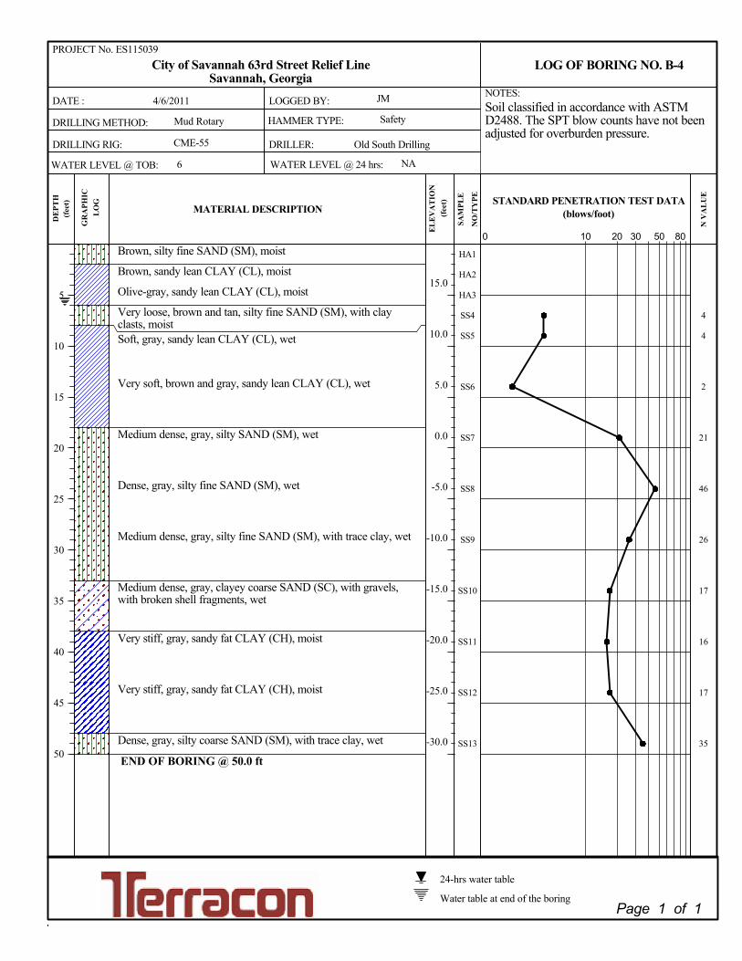
Brown, silty fine SAND (SM), moist
Brown, sandy lean CLAY (CL), moist
Olive-gray, sandy lean CLAY (CL), moist
Very loose, brown and tan, silty fine SAND (SM), with clayclasts, moistSoft, gray, sandy lean CLAY (CL), wet
Very soft, brown and gray, sandy lean CLAY (CL), wet
Medium dense, gray, silty SAND (SM), wet
Dense, gray, silty fine SAND (SM), wet
Medium dense, gray, silty fine SAND (SM), with trace clay, wet
Medium dense, gray, clayey coarse SAND (SC), with gravels,with broken shell fragments, wet
Very stiff, gray, sandy fat CLAY (CH), moist
Very stiff, gray, sandy fat CLAY (CH), moist
Dense, gray, silty coarse SAND (SM), with trace clay, wet
END OF BORING @ 50.0 ft
4
4
2
21
46
26
17
16
17
35
HA1
HA2
HA3
SS4
SS5
SS6
SS7
SS8
SS9
SS10
SS11
SS12
SS13
LOGGED BY:
DRILLING METHOD: HAMMER TYPE:
CME-55
50
Savannah, GeorgiaL
OG
* D _ T E *
WATER LEVEL @ TOB:
SAM
PLE
Soil classified in accordance with ASTMD2488. The SPT blow counts have not beenadjusted for overburden pressure.
* D _ T E *
DRILLER:
10
NO
/TY
PE
MATERIAL DESCRIPTION
0 30 80
STANDARD PENETRATION TEST DATA
(feet
)
Old South Drilling
5
10
15
20
25
30
35
40
45
50
WATER LEVEL @ 24 hrs:
DE
PTH
* D _ T E *
(blows/foot)
PROJECT No. ES115039
Water table at end of the boring
24-hrs water table
NOTES:
Safety
JM
N V
AL
UE
GR
APH
IC
4/6/2011
DRILLING RIG:
EL
EV
AT
ION
DATE :
20
Mud Rotary
City of Savannah 63rd Street Relief Line
6
LOG OF BORING NO. B-4
Page 1 of 1
NA
(feet
)
15.0
10.0
5.0
0.0
-5.0
-10.0
-15.0
-20.0
-25.0
-30.0

Light brown, silty SAND (SM), with trace clay, moist
Brown, silty fine SAND (SM), moist
Tan, silty fine SAND (SM), moist
Medium dense, brown and light orange, silty fine SAND (SM),moistMedium dense, brown and light orange, silty fine SAND (SM),moist
Medium dense, tan, silty fine SAND (SM), wet
Medium dense, tan, light orange and gray, silty fine SAND (SM),wet
Medium stiff, gray, sandy lean CLAY (CL), wet
Medium dense, gray, silty fine SAND (SM), wet
Medium dense, gray, silty SAND (SM), with clay clasts, wet
Medium dense, olive-gray, silty fine SAND (SM), wet
Medium dense, olive-gray, silty fine SAND (SM), wet
Medium dense, gray, silty coarse SAND (SM), wet
END OF BORING @ 50.0 ft
18
28
20
16
7
17
12
23
23
26
HA1
HA2
HA3
SS4
SS5
SS6
SS7
SS8
SS9
SS10
SS11
SS12
SS13
LOGGED BY:
DRILLING METHOD: HAMMER TYPE:
CME-55
50
Savannah, GeorgiaL
OG
* D _ T E *
WATER LEVEL @ TOB:
SAM
PLE
Soil classified in accordance with ASTMD2488. The SPT blow counts have not beenadjusted for overburden pressure.
* D _ T E *
DRILLER:
10
NO
/TY
PE
MATERIAL DESCRIPTION
0 30 80
STANDARD PENETRATION TEST DATA
(feet
)
Old South Drilling
5
10
15
20
25
30
35
40
45
50
WATER LEVEL @ 24 hrs:
DE
PTH
* D _ T E *
(blows/foot)
PROJECT No. ES115039
Water table at end of the boring
24-hrs water table
NOTES:
Safety
JM
N V
AL
UE
GR
APH
IC
4/6/2011
DRILLING RIG:
EL
EV
AT
ION
DATE :
20
Mud Rotary
City of Savannah 63rd Street Relief Line
6
LOG OF BORING NO. B-6
Page 1 of 1
NA
(feet
)
20.0
15.0
10.0
5.0
0.0
-5.0
-10.0
-15.0
-20.0
-25.0

Tan and light orange, silty fine SAND (SM), moist
Tan and light orange, silty fine SAND (SM), moist
Tan and light orange, silty fine SAND (SM), moist
Medium dense, gray, silty fine SAND (SM), wet
Medium dense, tan and light orange, silty fine SAND (SM), withclay clasts, wet
Soft, gray, lean CLAY (CL), wet
Medium dense, gray, silty fine SAND (SM), wet
Soft, gray, sandy lean CLAY (CL), with broken shell fragments,wet
Stiff, olive-gray, sandy SILT (ML), wet
Medium dense, gray, silty SAND (SM), wet
Stiff, olive-gray, sandy lean CLAY (CL), wet
Medium dense, gray, silty fine SAND (SM), wet
Medium dense, gray, silty coarse SAND (SM), wet
END OF BORING @ 50.0 ft
13
18
3
24
4
10
18
9
11
24
HA1
HA2
HA3
SS4
SS5
SS6
SS7
SS8
SS9
SS10
SS11
SS12
SS13
LOGGED BY:
DRILLING METHOD: HAMMER TYPE:
CME-55
50
Savannah, GeorgiaL
OG
* D _ T E *
WATER LEVEL @ TOB:
SAM
PLE
Soil classified in accordance with ASTMD2488. The SPT blow counts have not beenadjusted for overburden pressure.
* D _ T E *
DRILLER:
10
NO
/TY
PE
MATERIAL DESCRIPTION
0 30 80
STANDARD PENETRATION TEST DATA
(feet
)
Old South Drilling
5
10
15
20
25
30
35
40
45
50
WATER LEVEL @ 24 hrs:
DE
PTH
* D _ T E *
(blows/foot)
PROJECT No. ES115039
Water table at end of the boring
24-hrs water table
NOTES:
Safety
JM
N V
AL
UE
GR
APH
IC
4/6/2011
DRILLING RIG:
EL
EV
AT
ION
DATE :
20
Mud Rotary
City of Savannah 63rd Street Relief Line
4
LOG OF BORING NO. B-8
Page 1 of 1
NA
(feet
)
25.0
20.0
15.0
10.0
5.0
0.0
-5.0
-10.0
-15.0
-20.0

Dark brown, silty SAND (SM), with woods, with broken shellfragments, moistLight brown, silty SAND (SM), moistLight brown and light orange, clayey SAND (SC), moist
Dense, tan and light brown, fine SAND with silt (SP-SM), moist
Medium dense, tan and light brown, fine SAND with silt(SP-SM), moist
Very loose, gray, fine SAND with silt (SP-SM), wet
Very soft, gray lean CLAY (CL), wet
Loose, gray, silty coarse SAND (SM), with broken shellfragments, wet
Very soft, gray, sandy lean CLAY (CL), wet
Medium stiff, gray, lean CLAY (CL), wet
Medium stiff, gray, lean CLAY (CL), wet
Medium stiff, gray, sandy lean CLAY (CL), wet
Medium dense, gray, silty SAND (SM), wet
Medium dense, gray, silty SAND (SM), wet
END OF BORING @ 55.0 ft
33
27
4
1
7
2
7
5
5
13
37
HA1
HA2
HA3
SS4
SS5
SS6
SS7
SS8
SS9
SS10
SS11
SS12
SS13
SS14
LOGGED BY:
DRILLING METHOD: HAMMER TYPE:
CME-55
50
Savannah, GeorgiaL
OG
* D _ T E *
WATER LEVEL @ TOB:
SAM
PLE
Soil classified in accordance with ASTMD2488. The SPT blow counts have not beenadjusted for overburden pressure.
* D _ T E *
DRILLER:
10
NO
/TY
PE
MATERIAL DESCRIPTION
0 30 80
STANDARD PENETRATION TEST DATA
(feet
)
Old South Drilling
5
10
15
20
25
30
35
40
45
50
55
WATER LEVEL @ 24 hrs:
DE
PTH
* D _ T E *
(blows/foot)
PROJECT No. ES115039
Water table at end of the boring
24-hrs water table
NOTES:
Safety
JM
N V
AL
UE
GR
APH
IC
4/5/2011
DRILLING RIG:
EL
EV
AT
ION
DATE :
20
Mud Rotary
City of Savannah 63rd Street Relief Line
3
LOG OF BORING NO. B-10
Page 1 of 1
NA
(feet
)
20.0
15.0
10.0
5.0
0.0
-5.0
-10.0
-15.0
-20.0
-25.0
-30.0
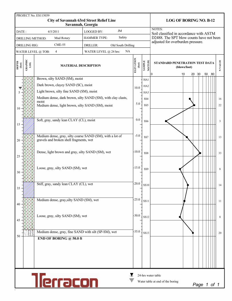
Brown, silty SAND (SM), moist
Dark brown, clayey SAND (SC), moist
Light brown, silty fine SAND (SM), moist
Medium dense, dark brown, silty SAND (SM), with clay clasts,moistMedium dense, light brown, silty SAND (SM), moist
Soft, gray, sandy lean CLAY (CL), moist
Medium dense, gray, silty coarse SAND (SM), with a lot ofgravels and broken shell fragments, wet
Dense, light brown and gray, silty SAND (SM), wet
Loose, gray, silty SAND (SM), wet
Stiff, gray, sandy lean CLAY (CL), wet
Medium dense, gray,silty SAND (SM), wet
Loose, gray, silty SAND (SM), wet
Medium dense, gray, fine SAND with silt (SP-SM), wet
END OF BORING @ 50.0 ft
16
22
3
13
33
8
14
11
8
20
HA1
HA2
HA3
SS4
SS5
SS6
SS7
SS8
SS9
SS10
SS11
SS12
SS13
LOGGED BY:
DRILLING METHOD: HAMMER TYPE:
CME-55
50
Savannah, GeorgiaL
OG
* D _ T E *
WATER LEVEL @ TOB:
SAM
PLE
Soil classified in accordance with ASTMD2488. The SPT blow counts have not beenadjusted for overburden pressure.
* D _ T E *
DRILLER:
10
NO
/TY
PE
MATERIAL DESCRIPTION
0 30 80
STANDARD PENETRATION TEST DATA
(feet
)
Old South Drilling
5
10
15
20
25
30
35
40
45
50
WATER LEVEL @ 24 hrs:
DE
PTH
* D _ T E *
(blows/foot)
PROJECT No. ES115039
Water table at end of the boring
24-hrs water table
NOTES:
Safety
JM
N V
AL
UE
GR
APH
IC
4/5/2011
DRILLING RIG:
EL
EV
AT
ION
DATE :
20
Mud Rotary
City of Savannah 63rd Street Relief Line
4
LOG OF BORING NO. B-12
Page 1 of 1
NA
(feet
)
10.0
5.0
0.0
-5.0
-10.0
-15.0
-20.0
-25.0
-30.0
-35.0

Hand Auger Boring Log
Project Name: City of Savannah 63rd Street Relief Line
Project Number: ES115039
Project Location: Savannah, Georgia
Depth Below Grade
(inch)
USCS
CLASSIFICATION
0 to 30 CL
30 to 60 CL
60 to 72 CL
Depth Below Grade
(inch)
USCS
CLASSIFICATION
0 to 24 SM
24 to 48 SP-SM
48 to 72 SM
Depth Below Grade
(inch)
USCS
CLASSIFICATION
0 to 36 SM
36 to 72 CL
Depth Below Grade
(inch)
USCS
CLASSIFICATION
0 to 12 SM
12 to 72 SM
Depth Below Grade
(inch)
USCS
CLASSIFICATION
0 to 72 SM
Depth Below Grade
(inch)
USCS
CLASSIFICATION
0 to 24 SM
24 to 72 CL
Depth Below Grade
(inch)
USCS
CLASSIFICATION
0 to 24 SM
24 to 72 CL
C-9
Material Description
Light brown, silty fine SAND, with trace roots
Light brown, sandy CLAY
Groundwater not Encountered
Groundwater not Encountered
Black and dark brown, sandy CLAY, with tan streaks
Tan and light orange, silty fine SAND, wet
Groundwater not Encountered
C-7
Material Description
Light brown and light orange, silty fine SAND
Material Description
Brown and light orange, silty SAND, w/ clay clasts
Black and dark brown, sandy CLAY, with tan/red streaks
Black and dark brown, sandy CLAY
Light brown, light orange and tan, silty fine SAND
Material Description
Tan, fine SAND with silt
Groundwater not Encountered
C-3
Material Description
C-5
Brown and light orange, sandy CLAY
Tan and light orange, silty SAND, with clay clasts
C-1
Material Description
Groundwater not Encountered
C-2
Groundwater not Encountered
Brown silty SAND, with clay clasts
C-11
Material Description
Light brown, silty fine SAND, with trace roots
Light brown, sandy CLAY
Groundwater not Encountered
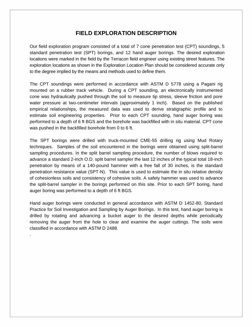
FIELD EXPLORATION DESCRIPTION
Our field exploration program consisted of a total of 7 cone penetration test (CPT) soundings, 5
standard penetration test (SPT) borings, and 12 hand auger borings. The desired exploration
locations were marked in the field by the Terracon field engineer using existing street features. The
exploration locations as shown in the Exploration Location Plan should be considered accurate only
to the degree implied by the means and methods used to define them.
The CPT soundings were performed in accordance with ASTM D 5778 using a Pagani rig
mounted on a rubber track vehicle. During a CPT sounding, an electronically instrumented
cone was hydraulically pushed through the soil to measure tip stress, sleeve friction and pore
water pressure at two-centimeter intervals (approximately 1 inch). Based on the published
empirical relationships, the measured data was used to derive stratigraphic profile and to
estimate soil engineering properties. Prior to each CPT sounding, hand auger boring was
performed to a depth of 6 ft BGS and the borehole was backfilled with in situ material. CPT cone
was pushed in the backfilled borehole from 0 to 6 ft.
The SPT borings were drilled with truck-mounted CME-55 drilling rig using Mud Rotary
techniques. Samples of the soil encountered in the borings were obtained using split-barrel
sampling procedures. In the split barrel sampling procedure, the number of blows required to
advance a standard 2-inch O.D. split barrel sampler the last 12 inches of the typical total 18-inch
penetration by means of a 140-pound hammer with a free fall of 30 inches, is the standard
penetration resistance value (SPT-N). This value is used to estimate the in situ relative density
of cohesionless soils and consistency of cohesive soils. A safety hammer was used to advance
the split-barrel sampler in the borings performed on this site. Prior to each SPT boring, hand
auger boring was performed to a depth of 6 ft BGS.
Hand auger borings were conducted in general accordance with ASTM D 1452-80, Standard
Practice for Soil Investigation and Sampling by Auger Borings. In this test, hand auger boring is
drilled by rotating and advancing a bucket auger to the desired depths while periodically
removing the auger from the hole to clear and examine the auger cuttings. The soils were
classified in accordance with ASTM D 2488.
.
APPENDIX B
SUPPORTING INFORMATION
Exhibit B-1 Laboratory Testing Exhibit B-2 Seismic Design Parameters Exhibit B-3 General Notes Exhibit B-4 Unified Soil Classification System

Project Name: City of Savannah 63rd Street Relief Line
Terracon Project No.: ES115039
Project Location: Savannah, Georgia
Lo
cati
on
Sa
mp
le N
o.
Sa
mp
le D
epth
(ft
)
Material Description
US
CS
Na
tura
l M
ois
ture
con
ten
t (%
)
#2
00
Pa
ssin
g (
%)
Pla
stic
In
dex
(%
)
Liq
uid
Lim
it (
%)
B-4 SS12 43 to 45 gray, sandy fat clay CH 101.7 44 123
B-6 SS5 8 to 10 brown and light orange, silty fine sand SM 12.8
B-6 SS8 23 to 25 gray, sandy lean clay CL 22.2 17 43
B-6 SS11 43 to 45 olive-gray, silty fine sand SM 20.0
B-10 SS5 8 to 10 tan and light brown, fine sand with silt SP-SM 10.1
B-12 SS5 8 to 10 light brown, silty sand SM 28.6
B-12 SS12 43 to 45 gray, silty sand SM 40.2
B-12 SS13 48 to 50 gray, fine sand with silt SP-SM 26.5 6.6
Summary of Soil Laboratory Test

IBC2006 General Procedure
Project Name: City of Savannah 63rd Street Relief Line
Project Number: ES115039
Conterminous 48 States
2003 NEHRP Seismic Design Provisions
Latitude = 32.03331
Longitude = -81.09746
Design Response Spectrum for Site Class D
SDs = 2/3 x SMs and SD1 = 2/3 x SM1
Site Class D - Fa = 1.486, Fv = 2.32
Period Sa Sd
(sec) (g) (inches)
0.000 0.156 0.000
0.095 0.389 0.035
0.200 0.389 0.152
0.477 0.389 0.866
0.500 0.371 0.907
0.600 0.309 1.088
0.700 0.265 1.270
0.800 0.232 1.451
0.900 0.206 1.633
1.000 0.186 1.814
1.100 0.169 1.996
1.200 0.155 2.177
1.300 0.143 2.358
1.400 0.133 2.540
1.500 0.124 2.721
1.600 0.116 2.903
1.700 0.109 3.084
1.800 0.103 3.265
1.900 0.098 3.447
2.000 0.093 3.6280.00
0.10
0.20
0.30
0.40
0.50
0.00 0.20 0.40 0.60 0.80 1.00 1.20 1.40 1.60 1.80 2.00
Desig
n S
pe
ctr
a (
g)
Period (sec)
IBC2006 General Procedure
IBC2006 General Procedure

GENERAL NOTES
DRILLING & SAMPLING SYMBOLS: SS: Split Spoon – 1-3/8" I.D., 2" O.D., unless otherwise noted H S: Hollow Stem Auger ST: Thin-Walled Tube - 2" O.D., unless otherwise noted PA: Power Auger RS: Ring Sampler - 2.42" I.D., 3" O.D., unless otherwise noted HA: Hand Auger DB: Diamond Bit Coring - 4", N, B RB: Rock Bit BS: Bulk Sample or Auger Sample WB: Wash Boring or Mud Rotary
The number of blows required to advance a standard 2-inch O.D. split-spoon sampler (SS) the last 12 inches of the total 18-inch penetration with a 140-pound hammer falling 30 inches is considered the “Standard Penetration” or “N-value”.
WATER LEVEL MEASUREMENT SYMBOLS: WL: Water Level WS: While Sampling N/E: Not Encountered WCI: Wet Cave in WD: While Drilling DCI: Dry Cave in BCR: Before Casing Removal AB: After Boring ACR: After Casing Removal
Water levels indicated on the boring logs are the levels measured in the borings at the times indic ated. Groundwater levels at other times and other locations across the site co uld vary. In pe rvious soils, the ind icated levels may reflect the locati on of groundwater. In low permeability soils, the accurate determination of groundwater levels may not be possible with only short-term observations.
DESCRIPTIVE SOIL CLASSIFICATION: Soil c lassification is based on the U nified C lassification S ystem. Coars e Graine d S oils have more than 50% of their dry weight retained on a #200 sieve; their principal descriptors are: boulders, cobbles, gravel or sand. Fine Grained Soils have less than 50% of their dry weight retained on a #200 sieve; they are principally described as clays if they are plastic, and silts if they are slightly plastic or non-plastic. Major constituents may be added as modifiers and minor constituents may be added according to the relative proportions based on grain size. In addition to gradation, coarse-grained soils are defined on the basis of their in-place relative density and fine-grained soils on the basis of their consistency.
CONSISTENCY OF FINE-GRAINED SOILS RELATIVE DENSITY OF COARSE-GRAINED SOILS
Unconfined Compressive
Strength, Qu, psf
Standard Penetration or N-value (SS)
Blows/Ft. Consistency
Standard Penetration or N-value (SS)
Blows/Ft. Relative Density
< 500 0 – 1 Very Soft 0 – 3 Very Loose 500 – 1,000 2 – 4 Soft 4 – 9 Loose
1,001 – 2,000 4 – 8 Medium Stiff 10 – 29 Medium Dense 2,001 – 4,000 8 – 15 Stiff 30 – 49 Dense 4,001 – 8,000 15 – 30 Very Stiff > 50 Very Dense
8,000+ > 30 Hard
RELATIVE PROPORTIONS OF SAND AND GRAVEL GRAIN SIZE TERMINOLOGY
Descriptive Term(s) of other Constituents
Percent ofDry Weight
Major Componentof Sample
Particle Size
Trace < 15 Boulders Over 12 in. (300mm) With 15 – 29 Cobbles 12 in. to 3 in. (300mm to 75 mm)
Modifier > 30 Gravel 3 in. to #4 sieve (75mm to 4.75 mm) Sand #4 to #200 sieve (4.75mm to 0.075mm) Silt or Clay Passing #200 Sieve (0.075mm)
RELATIVE PROPORTIONS OF FINES PLASTICITY DESCRIPTION
Descriptive Term(s) of other Constituents
Percent ofDry Weight
Term Plasticity
Index
Trace < 5 Non-plastic 0 With 5 – 12 Low 1 – 10
Modifiers > 12 Medium 11 – 30 High > 30

UNIFIED SOIL CLASSIFICATION SYSTEM
Criteria for Assigning Group Symbols and Group Names Using Laboratory Tests A Soil Classification
Group Symbol
Group Name B
Coarse Grained Soils: More than 50% retained on No. 200 sieve
Gravels: More than 50% of coarse fraction retained on No. 4 sieve
Clean Gravels: Less than 5% fines C
Cu ≥ 4 and 1 ≤ Cc ≤ 3 E GW Well-gr aded gravel F Cu < 4 and/or 1 > Cc > 3 E GP Poorl y graded gravel F
Gravels with Fines: More than 12% fines C
Fines classify as ML or MH GM Silty gravel F,G,H Fines classify as CL or CH GC Clayey gravel F,G,H
Sands: 50% or more of coarse fraction passes No. 4 sieve
Clean Sands: Less than 5% fines D
Cu ≥ 6 and 1 ≤ Cc ≤ 3 E SW Well-gr aded sand I Cu < 6 and/or 1 > Cc > 3 E SP Poorl y graded sand I
Sands with Fines: More than 12% fines D
Fines classify as ML or MH SM Silty sand G,H,I Fines classify as CL or CH SC Clayey sand G,H,I
Fine-Grained Soils: 50% or more passes the No. 200 sieve
Silts and Clays: Liquid limit less than 50
Inorganic: PI > 7 and plots on or above “A” line J CL Lean clay K,L,M PI < 4 or plots below “A” line J ML Silt K,L,M
Organic: Liquid limit - oven dried
< 0.75 OL Organic clay K,L,M,N
Liquid limit - not dried Organic silt K,L,M,O
Silts and Clays: Liquid limit 50 or more
Inorganic: PI plots on or above “A” line CH Fat clay K,L,M PI plots below “A” line MH Elastic Silt K,L,M
Organic: Liquid limit - oven dried
< 0.75 OH Organic clay K,L,M,P
Liquid limit - not dried Organic silt K,L,M,Q Highly organic soils: Primarily organic matter, dark in color, and organic odor PT Peat
A Based on the material passing the 3-in. (75-mm) sieve B If field sample contained cobbles or boulders, or both, add “with cobbles
or boulders, or both” to group name. C Gravels with 5 to 12% fines require dual symbols: GW-GM well-graded
gravel with silt, GW-GC well-graded gravel with clay, GP-GM poorly graded gravel with silt, GP-GC poorly graded gravel with clay.
D Sands with 5 to 12% fines require dual symbols: SW-SM well-graded sand with silt, SW-SC well-graded sand with clay, SP-SM poorly graded sand with silt, SP-SC poorly graded sand with clay
E Cu = D60/D10 Cc = 6010
2
30
DxD
)(D
F If soil contains ≥ 15% sand, add “with sand” to group name. G If fines classify as CL-ML, use dual symbol GC-GM, or SC-SM.
H If fines are organic, add “with organic fines” to group name. I If soil contains ≥ 15% gravel, add “with gravel” to group name. J If Atterberg limits plot in shaded area, soil is a CL-ML, silty clay. K If soil contains 15 to 29% plus No. 200, add “with sand” or “with gravel,”
whichever is predominant. L If soil contains ≥ 30% plus No. 200 predominantly sand, add “sandy” to
group name. M If soil contains ≥ 30% plus No. 200, predominantly gravel, add
“gravelly” to group name. N PI ≥ 4 and plots on or above “A” line. O PI < 4 or plots below “A” line. P PI plots on or above “A” line. Q PI plots below “A” line.