geotechnical engineering report - irp-cdn.multiscreensite.com · we have completed the geotechnical...
TRANSCRIPT
Daniel J. Holder, P.E., Inc. 2767 Scarborough Drive; Lake Charles, LA 70615 Consulting Civil / Geotechnical Engineer [email protected] (337) 274-4125
Geotechnical Engineering Report
Vinton Community Center & Gym Building 1615 Horridge Street
Vinton, Louisiana
for
Vincent Shows Architects 1502 South Huntington Street
Sulphur, LA 70663
prepared by
Daniel J. Holder, P.E., Inc. Consulting Civil / Geotechnical Engineer
2767 Scarborough Drive Lake Charles, LA 70615
DJH File 19-013 17 May 2019

Daniel J. Holder, P.E., Inc. Consulting Civil / Geotechnical Engineer
2767 Scarborough Drive Lake Charles, LA 70615 [email protected]
337-274-4125
17 May 2019 Vincent Shows Architects 1502 South Huntington Street Sulphur, LA 70663 Attn: Mr. Curtis Vincent, A.I.A. RE: Geotechnical Engineering Report Vinton Community Center & Gym Building
1615 Horridge Street Vinton, Louisiana DJH File 19-013
Dear Mr. Vincent: We have completed the Geotechnical Engineering Report for the referenced project, and are submitting the same herewith. This work was performed in general accordance with our written scope of work dated 08 March 2019, and was authorized by your email dated 21 March 2019. Please advise if you have any questions regarding this information, or if I may be of any additional assistance. It has been a pleasure working with you on this project.
Report Distribution: 1 copy, 1 electronic file (.PDF)

Geotechnical Engineering Report
Vinton Community Center & Gym Building 1615 Horridge Street
Vinton, Louisiana
DJH File 19-013; 17 May 2019
PROJECT INFORMATION 1. Description of Project. According to the information provided, it is understood that this project will consist of a new, one-story, Community Center and Gym building with associated site pavements. The new building will be approximately 31,500 square feet in plan with a 30 foot eave height, and will be of steel frame construction with metal siding and a sloped metal roof. Building loads were not provided, but are expected to be on the order of 20 to 40 kips per column and 2 to 4 kips per lineal foot for walls. The new building is to be located over an old, in-ground pool that was previously excavated and backfilled. Site pavements are expected to consist of Portland cement (PCC) and aggregate surfacing, with vehicle loadings limited to light passenger car and truck traffic and occasional delivery trucks and/or garbage trucks. The site is located at the existing Ward 7 Recreational facility, at 1615 Horridge Street, in Vinton, Louisiana. Refer to the Site Vicinity Map (Figure 1), the Google Earth® Aerial Photograph (Figure 2), and the Site Plan / Boring Location Plan (Figure 3) in the Appendix.
RESULTS OF INVESTIGATION 2. General. This investigation included the following work activities.
• a review of available geologic information; • a site reconnaissance by the project engineer; • five (5) soil borings to the 10 to 25 foot depth in the building and pavement areas; • laboratory testing of selected soil samples, • engineering analyses and evaluations, and, • the preparation of this report by the Geotechnical Engineer.
The locations of the soil borings are shown on Figures 2 and 3, and the Soil Boring Logs are included in the Appendix. The results of the field and laboratory testing programs are shown on the Soil Boring Logs, and on other figures in the Appendix, where applicable. Finally, a Description of the Field and Laboratory Testing Procedures is also included in the Appendix.

Geotechnical Engineering Report Vinton Community Center & Gym Building; Vinton, LA
DJH File 19-013; 17 May 2019
Page 2
3. Site Conditions. At the time of our investigation, the site consisted of an open, mowed grass lawn with a single palm tree located on the north edge of the planned building. The north side of the site is occupied by an existing in-ground pool and pool building, the west side by a pair of tennis courts (that are to be removed to make way for new site pavements), and the east and south sides by heavy woods (the latter a narrow treeline along the backyards of several residences). The site appears to be relatively flat and level, with an overall drop in site grades to the east by northeast (to the Vinton Drainage Canal some 150 feet or so to the north by northeast of the site). Drainage appears to be poor; shallow standing water from recent rains was observed across parts of the site. It is estimated that the center of the site is located at an approximate latitude and longitude of N 30o 10.989’ and W 93o 34.751’, respectively. The appropriate U.S.G.S. Topographic Map (i.e., Figure 1) indicates that the site is at an elevation of about +15 to +10 MSL. According to historic aerial photographs available on Google Earth® (e.g., Figure 2), it appears that the site has remained relatively unchanged since at least the September 2003 photograph (the remains of the old in-ground pool, a pool building, and a smaller, shallow pool are clearly evident in many of the historical aerial photographs, including the latest photograph used for Figure 2). In the February 1998 photograph, the earliest available on Google Earth®, it appears that the old pools and pool building are present, but the photograph is not clear enough to make definitive conclusions. It is clear, however, that the larger of the old in-ground pools and part of the pool building used to underly the planned location of the new building. According to the Geologic Map of Louisiana (Pope, et al, 1984), the site is underlain by the Prairie Formation of Pleistocene Age. These soils are described as “Light gray to light brown clay, sandy clay, silt, sand, and some gravel.” Please note that this discussion of site conditions is necessarily general in nature, and that a comprehensive description of current or previously existing site conditions is beyond the scope of this investigation. Reference is made to Figures 1, 2 and 3 in the Appendix, and the other sources noted herein.
Geotechnical Engineering Report Vinton Community Center & Gym Building; Vinton, LA
DJH File 19-013; 17 May 2019
Page 3
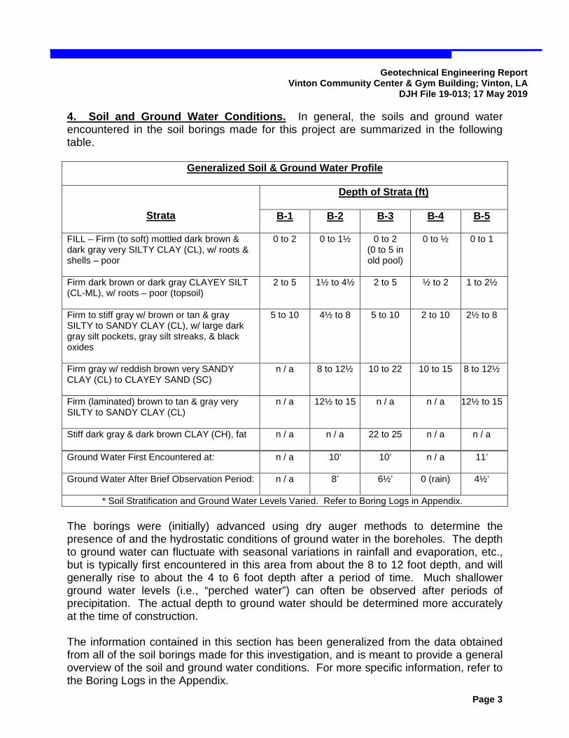
4. Soil and Ground Water Conditions. In general, the soils and ground water encountered in the soil borings made for this project are summarized in the following table.
Generalized Soil & Ground Water Profile
Strata
Depth of Strata (ft)
B-1 B-2 B-3 B-4 B-5
FILL – Firm (to soft) mottled dark brown & dark gray very SILTY CLAY (CL), w/ roots & shells – poor
0 to 2 0 to 1½ 0 to 2 (0 to 5 in old pool)
0 to ½ 0 to 1
Firm dark brown or dark gray CLAYEY SILT (CL-ML), w/ roots – poor (topsoil)
2 to 5 1½ to 4½ 2 to 5 ½ to 2 1 to 2½
Firm to stiff gray w/ brown or tan & gray SILTY to SANDY CLAY (CL), w/ large dark gray silt pockets, gray silt streaks, & black oxides
5 to 10 4½ to 8 5 to 10 2 to 10 2½ to 8
Firm gray w/ reddish brown very SANDY CLAY (CL) to CLAYEY SAND (SC)
n / a 8 to 12½ 10 to 22 10 to 15 8 to 12½
Firm (laminated) brown to tan & gray very SILTY to SANDY CLAY (CL)
n / a 12½ to 15 n / a n / a 12½ to 15
Stiff dark gray & dark brown CLAY (CH), fat
n / a n / a 22 to 25 n / a n / a
Ground Water First Encountered at:
n / a 10’ 10’ n / a 11’
Ground Water After Brief Observation Period:
n / a 8’ 6½’ 0 (rain) 4½’
* Soil Stratification and Ground Water Levels Varied. Refer to Boring Logs in Appendix. The borings were (initially) advanced using dry auger methods to determine the presence of and the hydrostatic conditions of ground water in the boreholes. The depth to ground water can fluctuate with seasonal variations in rainfall and evaporation, etc., but is typically first encountered in this area from about the 8 to 12 foot depth, and will generally rise to about the 4 to 6 foot depth after a period of time. Much shallower ground water levels (i.e., “perched water”) can often be observed after periods of precipitation. The actual depth to ground water should be determined more accurately at the time of construction. The information contained in this section has been generalized from the data obtained from all of the soil borings made for this investigation, and is meant to provide a general overview of the soil and ground water conditions. For more specific information, refer to the Boring Logs in the Appendix.
Geotechnical Engineering Report Vinton Community Center & Gym Building; Vinton, LA
DJH File 19-013; 17 May 2019
Page 4
GEOTECHNICAL RECOMMENDATIONS 5. General Considerations. The upper 2 to 5 feet or so of miscellaneous fills and silty soils are not considered suitable for the support of the building foundations, floor slabs, or pavements. These unsuitable materials (including the backfill from the old pool, etc.), any old building foundations and remnants of the old pool(s), and any soils disturbed by the clearing operations, should be removed and replaced with compacted select fill as part of the site preparation activities. These unsuitable materials should be removed and replaced with compacted select fill as part of the site preparation activities. Ideally, the undercut, when combined with the new fill that is to be placed to achieve the desired subgrade elevations, should provide a new, uniform building pad of compacted select fill that is at least 4 feet thick (i.e., 2 feet below the bottom of the footings and/or grade beams, and 4 feet below the bottom of the slab) or deeper as required. It is anticipated that the minimum required undercut will range from about 2 to 2½ feet on the south end of the building (e.g., B-4 and B-5) to as much as 5 feet or more in the center and north ends of the building (e.g., B-1, B-2 and B-3), especially beneath the old in-ground pool(s) and pool building. Recommendations for site preparation and earthwork activities are provided in Section 6. The new, uniform building pad described in the preceding paragraph should be suitable for the support of shallow foundations for the new building. The use of a reinforced slab foundation (i.e., a “ribbed slab”) is recommended to provide rigidity in the slab to help resist differential soil movements. The slab foundation may be conventionally reinforced (with “rebar” and welded wire mesh) or post-tensioned with high strength steel tendons. This approach has been used successfully on many projects in this area, but will not guarantee that some movements won’t occur, particularly under extreme conditions of moisture change (e.g., extended droughts or periods of excessive rainfall, etc.) and/or severe loading conditions. However, any such movements should be relatively minor, causing only cosmetic damages, if any; serious structural damage is not likely. Cosmetic damages that might occur include minor cracks in brick and masonry exteriors and interior finishes and floor slabs, slight unlevelness of floors and other horizontal surfaces, and door and window jambs that “stick” or become slightly out of square (these types of damages could also occur from many other sources). In any event, the higher the quality of the earthwork construction, and the stiffer the foundation is constructed, the less likely are the chances for the movements described above. Recommendations for shallow foundations are provided in Section 7. If the possibility of these minor movements is not acceptable and/or heavier building loads are anticipated, then drilled, cast-in-place concrete shafts should be utilized to support the new building, along with a floor slab-on-grade supported on the new uniform building pad described above. Drilled shafts are especially suitable for supporting large

Geotechnical Engineering Report Vinton Community Center & Gym Building; Vinton, LA
DJH File 19-013; 17 May 2019
Page 5
column loads and resisting lateral loads and overturning moments typical of metal buildings with large eave heights. Excavations for drilled shafts in the clayey soils at this site are expected to remain relatively stable (i.e., not cave and/or become “quick” at the bottom); however, excavations in sandy soils (e.g., between about the 8 to 22 foot depth, or so) will be problematic, and will likely require full depth temporary steel casing and/or full depth drilling slurry to remain stable. The contractor should be thoroughly experienced with the use of these drilling techniques or significant construction difficulties and/or inadequate shaft sections could result. Recommendations for drilled shafts are provided in Section 8. It is anticipated that the complete removal and replacement of the unsuitable shallow soils may not be economical for the support of the site pavements planned for this project. In these areas, although less desirable, consideration may be given to stripping only the vegetation and any unsuitable soils containing roots and/or organic matter (e.g., the top foot or so), and placing fill for the support of the pavement section on the resulting subgrade surface, provided it is firm enough to support the construction activities. (This option should only be considered with the understanding that the performance and/or life of the pavements may be compromised, and/or that some construction difficulties could result. If the subgrade is wet or yields excessively under construction activities, then all unsuitable fills and/or silty soils should be completely removed and replaced with new fill.) Recommendations for Site Preparation and Earthwork Activities are provided in Section 6; recommendations for Site Pavements are provided in Section 9. Establishing and maintaining good drainage will be critical for earthwork and foundation construction at this site; otherwise, significant construction difficulties and/or additional measures (e.g., additional undercutting, subgrade stabilization, etc.) can be expected to be required. If dewatering is necessary, sump and pump methods should be suitable if large enough pumps are utilized and the contractor is diligent; otherwise, well points may be required. Performing earthwork operations during wet weather conditions and/or after long, wet periods should be avoided. 6. Site Preparation and Earthwork Activities. As noted in Section 5, establishing and maintaining good drainage will be critical for earthwork and foundation construction at this site. Poor drainage and/or wet conditions at the time of construction can be expected to cause delays and/or cost overruns due to additional undercutting or treatment measures. The contractor should be required to make every reasonable effort to provide dry working conditions (i.e., cut drainage ditches prior to earthwork activities; thoroughly “process,” or dry the subgrade soils, if necessary; and take advantage of dry weather conditions; etc.). The upper 2 to 5 feet or so of miscellaneous fills and/or silty soils should be completely removed from the building areas to the minimum depth required to provide the recommended uniform building pad of select fill, as described in Section 5. Along with

Geotechnical Engineering Report Vinton Community Center & Gym Building; Vinton, LA
DJH File 19-013; 17 May 2019
Page 6
the fills and silty soils, any other unsuitable materials such as tree roots, old building debris, underground utilities, pool walls and/or bottoms and old backfill, or any other miscellaneous materials should be removed to the expose stiff natural clayey subgrade soils. The exposed clay subgrade surface should be inspected to ensure that a suitable surface exists upon which to place select fill. This inspection may include proofrolling the subgrade with a loaded, tandem-axle dump truck or other means as determined by the inspector. The clayey subgrade material will be sensitive to moisture, and will likely pump and rut excessively if it is wet and/or if exposed to excessive (or even moderate) construction traffic. Any areas that are determined to be unsuitable for fill placement by the inspector should be further undercut or treated to achieve a stable subgrade surface. The project documents should specify a “base” undercut depth, and include unit rates for additional or less undercut and/or treatment based on the results of the subgrade inspection. The contractor should be required to make every reasonable effort to provide dry working conditions before treatment is considered. Treatment of the clay subgrade may be considered, if necessary, to help provide a firm working table upon which to conduct fill operations. Lime treatment should be effective for the clayey subgrade soils and should be performed in general accordance with LA DOTD Standard Specifications for Roads and Bridges, Section 304, Lime Treatment, Type D, Working Table. A treatment percentage of 6 to 8 percent (by volume) may be assumed for planning purposes, along with a treatment depth of 8 to 12 inches (see below). Treatment of the silty soils may be considered in the pavement areas, as noted in Section 5; however, all roots and organic matter and any other deleterious materials must be removed, and treatment must provide a suitable surface upon which to conduct further construction activities. Lime is not expected to be an effective treatment agent in these silty soils; cement or lime-flyash treatment will probably be required. Treatment should be performed in general accordance with LA DOTD Standard Specifications for Roads and Bridges, Section 305, Subgrade Layer. A treatment percentage of 7 percent (by volume) may be assumed for planning purposes, along with a treatment depth of 8 to 12 inches (see below). Treatment percentages can vary based on normal variations in soil type, moisture content, weather conditions, etc. The contractor should be required to determine the actual treatment percentages prior to construction using representative samples of the subgrade soils, and submit same for the engineer’s review. The treatment percentages should be determined in the lab using a procedure similar to LA DOTD TR 432, or test strips may be constructed and evaluated in the field. The project documents should allow for an adjustment of the treatment percentages based on the results of the lab or field tests.
Geotechnical Engineering Report Vinton Community Center & Gym Building; Vinton, LA
DJH File 19-013; 17 May 2019
Page 7
Treatment depths can vary depending upon the capacity (i.e., the size and weight, etc.) of the equipment used for treatment and the performance of the treated subgrade under subsequent construction activities. The treatment depth should not exceed that which can be thoroughly mixed and compacted with the proposed construction equipment, but must be sufficient to support all subsequent construction activities. Typical treatment depths range from about 8 to 12 inches. The project documents should allow for an adjustment of the treatment depth based on the contractor’s proposed equipment and on the performance of the initial treatment operations. A full depth, in-place mixer (i.e., a stabilizer machine) should be utilized for all treatment operations; farm discs, etc., will not be effective. The contractor should be responsible for determining the excavatability of the treated subgrade soils for any future excavations. Once a firm subgrade exists upon which to conduct fill operations, select fill may be placed to achieve the desired building pad elevation. The surface of the new building pad should extend a minimum horizontal distance of 10 feet outside the exterior building lines, and the surface of the pad should be sloped at a minimum of 10 Horizontal to 1 Vertical (10H:1V), but no steeper than 3H:1V, to facilitate drainage away from the building foundations. Fill should only be placed on horizontal surfaces, and “benched” into the side of any existing slopes. Each “bench” should be cut sufficiently deep to expose the clayey soils described above, at least 2 feet wide, and no more than 1 foot high as the benches ”step up” to meet the desired subgrade elevation. Select fill should consist of a silty or sandy clay with a Liquid Limit of 30 to 42 and a Plasticity Index of 12 to 22. Fill should be placed in 6 to 8 inch thick loose lifts or less and compacted to 95% of the Standard Proctor Maximum Dry Density at +2% of the Optimum Moisture Content (ASTM D 698). Each lift should be tested to ensure compliance with these recommendations prior to placing subsequent lifts. A minimum testing frequency of one test per 2,500 square feet, but not less than 3 tests, per lift is recommended. All site preparation and earthwork activities should be inspected and tested by qualified Construction Material Testing (CMT) personnel experienced in earthwork construction. This should include full-time inspection of the site preparation and testing of fill placement and compaction. These services are essential for the reliable construction of the building pad for this project. 7. Shallow Foundations. Following the completion of the Site Preparation and Earthwork activities described in Section 6, shallow foundations should be suitable for the support of the new building, provided some nominal settlement and/or other minor soil movements can be tolerated, as described in Section 5. A reinforced slab foundation is recommended to help accommodate soil movements.
7.1 Reinforced Slab (or “Ribbed”) Foundation. A reinforced slab foundation consists of a monolithic slab-on-grade with turned-down edges (perimeter grade
Geotechnical Engineering Report Vinton Community Center & Gym Building; Vinton, LA
DJH File 19-013; 17 May 2019
Page 8
beams); interior grade beams may be included if required by the building loads and/or stiffness considerations. The perimeter grade beams function as shallow foundations to carry the exterior wall loads and serve to cutoff moisture fluctuations in the soils supporting the slab from the surrounding environment. Interior grade beams serve to stiffen the slab system, allowing it to better accommodate movements in the supporting soils. Interior grade beams should be located beneath any load bearing interior walls and/or columns, in which case they should be designed as a shallow foundation. The spacing and dimensions of the interior grade beams should be determined by the structural engineer, if applicable; typically, a maximum spacing of 15 feet or less (each way) is utilized. Adequate reinforcement, as determined by the structural engineer, should be provided in the slab-on-grade foundation and grade beams. The entire slab system should be placed monolithically (in one pour), or dowelled to provide equivalent rigidity.
The slab foundation may be reinforced with conventional reinforcing steel (rebar and welded wire mesh) or post tensioned steel tendons (i.e., a post-tensioned slab). The grade beam and slab dimensions and reinforcement of either foundation system should be determined by a qualified design professional knowledgeable in the design of slabs-on-grade. It is recommended that consideration be given to placing a suitable polyethylene vapor barrier and a granular leveling layer beneath the floor slab. The practice of and the details of using a vapor barrier and/or granular leveling layer beneath slabs are left to the discretion of the project designer. 7.2 Bearing Capacity and Soil Movements. Shallow foundations or load bearing grade beams should bear within the new, properly placed and compacted fill pad described in Section 5. Shallow foundations or load bearing grade beams bearing designed in accordance with these recommendations may be designed for a maximum net allowable soil bearing capacity of 2,000 pounds per square foot (psf); capacities for column footings may be increased to 2,600 psf. The exterior foundations and grade beams should extend to a depth of at least 2 feet below finished exterior grades to help minimize moisture fluctuations in the foundation soils. Net allowable soil capacities take into account the weight of the concrete and backfill below grade; thus, no adjustments to the design loads are necessary. The bearing capacities provided in this section include a factor of safety of at least 2 against shear failure of the bearing soils. A minimum footing or grade beam width of 18 inches (24 inches for column footings) is recommended to minimize the possibility of shear “punch” failure of the bearing soils.

Geotechnical Engineering Report Vinton Community Center & Gym Building; Vinton, LA
DJH File 19-013; 17 May 2019
Page 9
Post-construction soil movements from normal foundation settlements are expected to be on the order of one inch or less. Differential movements should be about one-half to two-thirds of the total observed movement. 7.3 Rectangular Footings and Overturning. Capacities for rectangular footings may be increased according to the following formula: qr = qw (1 + 0.3 B/L) where qr = net allowable bearing pressure for rectangular footings (psf)
qw = net allowable bearing pressure for continuous footings given in Section 7.2 (psf)
B = footing width L = footing length (L>B) Resistance to overturning loads should only consider the effective footing area, i.e., the portion of the footing centered beneath and effective in carrying the load. The equivalent footing dimensions B’ and L’ of the effective footing area are defined as:
B’ = B – 2eB and L’ = L – 2eL where eB and eL are the eccentricity in each direction. Eccentricity is defined as the moment (M) divided by the axial load (P), or
eB = MB / PB and eL = ML / PL 7.4 Lateral Loads. Lateral loads on the foundation will be resisted by sliding resistance between the base of the foundation and the underlying soil and by lateral earth pressure against the side of the foundation; the latter should be neglected for shallow foundations for this project. The allowable sliding resistance, fs, all, may be taken as 0.2 times the applied bearing pressure, not to exceed a value of 250 psf. This is an allowable value; a safety factor of about 1½ to 2 against sliding resistance has already been included. 7.5 Uplift Loads. Foundations placed to depths of about 4 feet or less should be designed for uplift by taking into account the dead weight of the concrete and any overlying backfill. A typical unit weight of 120 pounds per cubic foot (pcf) should be utilized for the soil backfill if properly placed and compacted (refer to Section 6). Granular soils should not be used for backfill over foundations subject to uplift because the soils could become saturated if poor drainage exists. Buoyant unit weights (i.e., subtract the unit weight of water, 62.4 pcf) should be used for uplift calculations if proper drainage cannot be assured.
Geotechnical Engineering Report Vinton Community Center & Gym Building; Vinton, LA
DJH File 19-013; 17 May 2019
Page 10
7.6 Construction Considerations. Shallow excavations (i.e., 4 feet deep or less) for foundations in firm clayey soils at this site should remain stable (i.e., should not cave) for short periods of time, particularly in the absence of surface or ground water. Deeper excavations, excavations in sandy soils, or excavations that remain open for longer periods of time could be subject to significant ground or surface water intrusion. The reinforcing steel and concrete for the foundations should be placed expeditiously following the completion of the excavation. The excavations should not be permitted to stand open any longer than necessary. Any water that may accumulate in the excavations should be pumped out immediately. The soils at this site can become significantly weaker if wetted or disturbed during the construction operations. Traffic in the excavations should be prohibited, and drainage should be provided to direct surface and ground water (if any) away from the excavations. If the concrete for the foundation will not be placed on the same day as the excavation, a “mud mat” of lean concrete should be placed to protect the bearing surface. According to OSHA regulations (CFR 1926.650 through 1926.652, and Appendix A to Subpart P), the contractor is responsible for developing and maintaining the appropriate safety systems for excavations on the project. The soils should be classified as Type C for this purpose. Recommendations for temporary slopes and/or shoring are beyond the scope of this investigation, but can be provided upon request once more specific design details are available. All excavation and concreting operations should be inspected and tested by qualified Construction Material Testing (CMT) personnel experienced in shallow foundation construction. This should include full-time inspection of the foundation excavations and testing of concrete placement. These services are essential for the reliable construction of shallow foundations for this project.
8. Drilled Shaft Foundations. As noted in Section 5, drilled shaft foundations may also be considered for the support of the new building for this project. Drilled shafts are especially suitable for supporting large column loads and resisting lateral loads and overturning moments. Straight-sided drilled shafts should be utilized for this project; belled (underreamed) shafts are not recommended. Excavations for drilled shafts in the clayey soils at this site are expected to remain relatively stable (i.e., not cave and/or become “quick” at the bottom); however, excavations in sandy soils (e.g., between about the 8 to 22 foot depth, or so) will be problematic, and will likely require full depth temporary steel casing and/or full depth drilling slurry to remain stable. The contractor should be thoroughly experienced with the

Geotechnical Engineering Report Vinton Community Center & Gym Building; Vinton, LA
DJH File 19-013; 17 May 2019
Page 11
use of these drilling techniques or significant construction difficulties and/or inadequate shaft sections could result. Refer to Section 8.5 for construction considerations.
8.1 Axial Capacity. The compressive axial capacity of drilled shafts is derived from skin friction at the soil-shaft interface and end bearing. Uplift resistance is provided by skin friction and the buoyant weight of the shaft. A number of shaft diameters and embedment depths were considered in order to allow the project designer to select the most suitable shaft geometry for the specific loading conditions. These values are tabulated below. The allowable shaft capacities include factors of safety of 2 and 2.5 for skin friction and end bearing in compression, respectively, and 2.5 for skin friction in uplift. The buoyant unit weight of the shaft is also included in the provided uplift capacities, along with a factor of safety of 1.1. The upper 4 feet has been neglected for surface effects and/or grade beams, etc. Capacities for intermediate diameters and/or depths may be interpolated from the table. Extrapolation beyond the specified diameters and depths is not recommended without further consultation. Allowable Compression/Uplift Loads for Single Drilled Shaft Foundations (kips)
Depth* (ft) 18 Inch Diameter 24 Inch Diameter
8 14 / 7 20 / 10
10** 18 / 11 27 / 15
15** 29 / 21 42 / 28
20** 41 / 31 58 / 42
* Depth Refers to Depth Below Existing Site Grades.
** Not Recommended without Full Depth Temporary Steel Casing +/or Drilling Slurry All shaft capacities provided are based on good quality construction procedures being utilized. Sufficient full depth reinforcement, as determined by the structural engineer, is required to develop the full tensile capacity of the shaft. 8.2 Settlement. Total settlements for drilled shaft foundations designed and constructed in accordance with these recommendations are estimated to be about one-half inch or less. Differential settlements between adjacent shafts should be about one-half to three-quarters of the observed total settlement. 8.3 Lateral Loads and Overturning Moments. The evaluation of lateral loading and overturning moment combinations on drilled shafts can be relatively complex and time consuming for a large number of shaft geometries, especially if the specific

Geotechnical Engineering Report Vinton Community Center & Gym Building; Vinton, LA
DJH File 19-013; 17 May 2019
Page 12
loading conditions are not known. Once the final loading conditions on the drilled shafts are known, this office should be contacted for further evaluation. 8.4 Shaft Spacing and Group Effects. Shafts should be spaced a minimum of 2.5 to 3 diameters center-to-center or 5% of the shaft length, whichever is greater. Large groups of shafts are not anticipated; however, if groups of 5 or more shafts are utilized, the Geotechnical Engineer should be permitted to evaluate group efficiencies. 8.5 Construction Considerations. Excavations for drilled shafts in the clayey soils at this site are expected to remain relatively stable (i.e., not cave and/or become “quick” at the bottom); however, excavations in sandy soils (e.g., between about the 8 to 22 foot depth, or so) will be problematic, and will likely require full depth temporary steel casing and/or full depth drilling slurry to remain stable. The contractor should be thoroughly experienced with the use of these drilling techniques or significant construction difficulties and/or inadequate shaft sections could result. Drilling slurry, if utilized, should be introduced into the excavation immediately upon drilling, and maintained at full depth during the drilling and concreting operations. The excavation and concrete placement should proceed as expeditiously as possible. Once the excavation is started, it should be completed and concrete placed without delay. The slurry should be premixed and brought to the proper consistency, etc., before introducing into the excavation. The drilling tools (augers) should be designed such that the slurry can pass freely around or through the tool as the auger is withdrawn, and the auger should be operated slowly enough that suction does not develop beneath the auger and cause caving. The bottom of the excavation should be cleaned out with an air lift pump or similar device; a clean-out bucket is not recommended. Prior to cleanout, the slurry should be allowed to stand undisturbed for about 15 to 30 minutes to allow all suspended solids to settle out. The reinforcing steel and concrete for the shaft should be placed immediately after the clean out operations are complete. The reinforcing cage should be fixed in place with centralizers or other means so that it is not disturbed by the concrete placement. If temporary steel casing is used achieve a dry excavation, the concrete may be dropped freely through the excavation, provided it is not permitted to strike any obstructions on the way down and does not land in standing water. If this cannot be achieved, a full depth tremie should be utilized to place the concrete. A “head” of concrete of at least 5 feet above the bottom of the casing should be maintained while the temporary casing is withdrawn. If drilling slurry is utilized, the concrete should be placed by means of a full depth, water-tight tremie with a valve or other means of separating the slurry from the

Geotechnical Engineering Report Vinton Community Center & Gym Building; Vinton, LA
DJH File 19-013; 17 May 2019
Page 13
concrete (e.g., a pig). The concrete should be proportioned so that it has the proper strength as determined by the project designers, while maintaining a slump of 6 to 8 inches at the time of placement. This is critical to ensure that the slurry is completely displaced, and that no voids remain within the completed shaft. All drilling and concreting operations should be observed by qualified personnel experienced in drilled shaft inspection techniques. According to OSHA regulations (CFR 1926.650 through 1926.652, and Appendix A to Subpart P), the contractor is responsible for developing and maintaining the appropriate safety systems for excavations on the project. The soils should be classified as Type C for this purpose. Recommendations for temporary slopes and/or shoring are beyond the scope of this investigation, but can be provided upon request once more specific design details are available. All drilling and concreting operations should be inspected and tested by qualified Construction Material Testing (CMT) personnel experienced in drilled shaft construction. This should include full-time inspection of the shaft excavations and testing of concrete placement. These services are essential for the reliable construction of drilled shafts for this project.
8.6 Floor Slab. As long as the site preparation and earthwork activities are properly performed, as described in Section 6, the floor slab may consist of a ground supported slab-on-grade placed monolithically with exterior and interior grade beams. The grade beams should be designed to rest upon and span across the drilled shaft foundations. The exterior grade beams should extend to a minimum depth of 2 feet below exterior finished grade to help minimize moisture fluctuations of the soils supporting the floor slab. The interior grade beams may be placed at any convenient depth as required by the structural considerations for the floor slab system. The spacing of the interior grade beams should be determined by the structural engineer. Typically, the interior beam spacing matches the drilled shaft layout; in any case, a maximum spacing of 15 feet or less (each way) is generally utilized. Sufficient reinforcement (for both positive and negative moments) and control joint spacing, as determined by the structural engineer, should be utilized. It is recommended that consideration be given to placing a suitable polyethylene vapor barrier and a granular leveling layer beneath the floor slab. The practice of and the details of using a vapor barrier and/or granular leveling layer beneath the slab are left to the discretion of the designer of record.
9. Pavements. Following the completion of the Site Preparation and Earthwork activities described in Section 6, the prepared subgrade should be suitable for the support of the project pavements. The success of any pavement system depends primarily on the following factors: traffic volume and wheel (or axle) loadings, drainage,

Geotechnical Engineering Report Vinton Community Center & Gym Building; Vinton, LA
DJH File 19-013; 17 May 2019
Page 14
construction quality, and regular inspection and maintenance. These considerations are discussed in Section 9.1. It has been the experience of this author that Portland cement concrete (PCC) pavements generally perform better than asphaltic concrete (AC) pavements in this area, and thus are recommended for use on this project. PCC pavements generally require a larger initial investment; however, future maintenance costs are generally less than that of AC pavements. Recommendations for PCC pavements are provided in Section 9.2. The previous paragraph notwithstanding, properly designed and maintained asphalt pavements can also perform satisfactorily for projects of this type, and are discussed for the project designer’s consideration. AC pavements generally involve less initial investment, although greater future maintenance costs are involved. Recommendations for AC pavements, if desired, can be provided upon request. We understand that some aggregate surfacing is also planned for this project. Aggregate surfacing can provide a suitable pavement surface, as intended; however, frequent and routine addition of new aggregate and regrading should be expected to maintain a suitable aggregate surface. Recommendations for aggregate surfacing are provided in Section 9.3.
9.1 General Considerations for Pavement Systems.
• Traffic Loading Conditions. Pavement sections should be designed to
accommodate the anticipated traffic volume and loadings. Overloading pavement sections through excessive wheel loads and/or repetitions will lead to premature pavement failure.
It is anticipated that traffic loading conditions for this project will be limited to site access and parking for light patron traffic and parking, and occasional delivery and/or dumpster vehicles. It is further expected that the larger vehicles will be separated from the parking areas of patron vehicles and limited to specific traffic lanes.
• Drainage. Establishing and maintaining good drainage is essential to the
successful performance of pavements. Without good drainage conditions, premature pavement failure can be expected. The final subgrade surface should be contoured to channel surface and subsurface water away from the pavements. If site grades allow, the pavement sections should be elevated so that an aggregate base course can drain freely. Otherwise, a soil-cement base or other such base that will not trap water beneath the pavements should be utilized.
Geotechnical Engineering Report Vinton Community Center & Gym Building; Vinton, LA
DJH File 19-013; 17 May 2019
Page 15
• Construction Quality. Quality construction practices and inspection services are essential for the successful installation and performance of pavements. Construction inspection services by Geotechnical Engineer’s representative are considered essential for this phase of the project.
• Inspection and Maintenance. A regular inspection and maintenance program
should be conducted to ensure that the pavement is maintained in good operating condition. The pavements should be inspected regularly to verify that adequate drainage is maintained and that all joints are properly sealed and free of vegetation or debris. When pavement distress is noted, the appropriate measures (e.g., patching, sealing, resurfacing, etc.) should be performed to keep the pavements in good operating condition.
9.2 Portland Cement Concrete (PCC) Pavements. The automobile parking pavement section should consist of 5 inches of concrete (minimum compressive strength of 3,000 psi) underlain by 4 inches of crushed aggregate or 6 inches of soil-cement base. The aggregate should meet the gradation requirements of LA DOTD Section 1003.03.1 Stone. Locally available products known as 610 Road Base or No. 57 Stone, although not strictly meeting 1003.03.1, should be suitable for use as base material. Traffic lanes should consist of 6 inches of concrete (8 inches beneath any bus, heavy truck or dumpster traffic) underlain by 4 inches of crushed, well graded aggregate or 6 inches of soil-cement base. The PCC pavement should be at least 9 inches thick in the dumpster loading zone, if applicable. A suitable non-woven geotextile (US Fabrics US 160NW, or equal) should be provided between the aggregate base and the subgrade to prevent the mixing of the base and subgrade. If suitable drainage cannot be provided for a granular base, a 6 inch thick soil-cement base should be utilized. The soil-cement base, if utilized, should be constructed in accordance with LA DOTD Standard Specifications for Roads and Bridges Section 303. A treatment percentage of 10% cement (by volume) may be used for planning purposes; however, the appropriate treatment percentage should be determined by additional laboratory testing prior to construction using LA DOTD Testing Procedure Manual TR 432. Appropriate reinforcement as determined by the design engineer should be used and adequate control joint spacing (15 feet or less is suggested) should be observed. Pavements should be isolated from building foundations by means of suitable expansion and/or control joints, if applicable. All aspects of the pavement design and construction should conform to the American Concrete Institute (ACI) Standard 330R-08: Guide for Design and Construction of Concrete Parking Lots, the LA DOTD Standard Specifications for
Geotechnical Engineering Report Vinton Community Center & Gym Building; Vinton, LA
DJH File 19-013; 17 May 2019
Page 16
Roads and Bridges, Section 601 - Portland Cement Concrete, and other applicable engineering specifications. 9.3 Aggregate Surfacing. Following the completion of the Site Preparation and Earthwork activities described in Section 6, the prepared subgrade should be suitable for the support of the planned aggregate surfaced areas. An aggregate thickness of at least 6 inches is recommended for areas that will support light passenger car and truck traffic and parking. The aggregate should be well graded, durable, and crushed (i.e., angular), and meet the gradation requirements of LA DOTD Section 1003.03.1, Stone. Locally available products known as 610 Road Base or No. 57 Stone, although not strictly meeting 1003.03.1, should be suitable for use. A suitable non-woven geotextile (e.g., US Fabrics US 160NW, or equal) should be provided between the aggregate and the subgrade to prevent the mixing of the aggregate and subgrade. The use of a suitable biaxial geogrid (e.g., Tensar TX-130S, or equal) could be considered to provide additional structural capacity and/or reduce the aggregate thickness. The aggregate should be compacted with a smooth drum roller until no deflection is observed. It should be anticipated that the placement and grading of additional aggregate will be required in any areas that deflect excessively under the compaction operations. The long term performance of the aggregate parking area will depend upon the quality of the initial construction, the degree to which good drainage exists, and the frequency and magnitude of the vehicular loads. In any case, regular placement and grading of additional aggregate should be anticipated to maintain the condition of the aggregate surface, particularly in areas where traffic is channeled into distinct lanes and/or in turning areas (e.g., the entrance way). Proper drainage should be provided to direct surface water away from the completed aggregate surfaces. 9.4 General. Note that the pavement sections provided in this report were derived from the experience of this firm based on similar projects that have been observed to perform satisfactorily over the last 15 years. Rigorous pavement designs have not been performed because traffic data was not provided for that purpose. Minor deviations from the pavement sections provided in this section should not necessarily be detrimental to the performance of the pavements at this site, provided traffic is limited to light passenger traffic, a good subgrade is established and fill placement is of high quality, and good construction practices are utilized when constructing the pavements (especially observing minimum specified pavement thicknesses). We will be happy to provide additional analyses for the pavement sections if requested.

Geotechnical Engineering Report Vinton Community Center & Gym Building; Vinton, LA
DJH File 19-013; 17 May 2019
Page 17
All pavement construction activities should be inspected and tested by qualified Construction Material Testing (CMT) personnel experienced in pavement construction. This should include full-time inspection of the subgrade preparation and testing of concrete and/or asphalt placement and compaction. These services are essential for the reliable construction of the pavements for this project.
OTHER GEOTECHNICAL CONSIDERATIONS 10. Drainage and Landscaping. Proper long term drainage should be provided to direct surface water away from the completed building foundations and pavements. Gutters and downspouts, as well as positive site grading, should be utilized for this purpose as required. Landscaping near the building foundations should be avoided to minimize fluctuations in the moisture contents of the surrounding soils, or a suitable drainage barrier (e.g., geosynthetic liner) should be utilized. Trees should be located no closer to the building foundations than the drip line of the mature tree canopy. 11. Additional Consulting Services. The Geotechnical Engineer should be kept informed of and permitted to address all aspects of the soils-related aspects of the project. Often, concerns may arise that are not specifically addressed by the Geotechnical Engineering Report. A brief conference can often address any such concerns, and can identify any other issues not anticipated by the design team. Upon completion of design, and prior to the start of construction, the Geotechnical Engineer should be provided with the opportunity to review the design drawings and specifications to assure compliance with the Geotechnical Engineering Report. Such review is considered to be an integral part of the recommendations of this report. 12. Construction Materials Testing (CMT) Services. Construction Materials Testing (CMT) services for this project are essential to assure that the soil conditions do not vary from that assumed in this report and to ensure that the recommendations in this report are followed. These services should be retained by the owner to assure that unbiased reporting is provided. The Geotechnical Engineer of Record should be provided with timely copies of all test results. Otherwise, the suitability of these recommendations and/or the performance of the earthwork and foundations for this project cannot be assured. 13. Limitations. This report is based upon the information provided by the owner’s representative, as well as the soil and ground water conditions encountered during the field investigation. Variations may occur away from or between the borehole locations. If such variations become apparent, or if the nature of the project changes significantly, the Geotechnical Engineer should be consulted for additional recommendations.
Geotechnical Engineering Report Vinton Community Center & Gym Building; Vinton, LA
DJH File 19-013; 17 May 2019
Page 18
The recommendations in this report pertain only to the soils-related aspects of the project. The structural design of the building foundations is beyond the scope of these services. Likewise, this report does not address the environmental aspects of the project. We would be pleased to assist with these additional services if requested. 14. Compliance with Applicable Standards and Regulations. All geotechnical and related civil aspects of this project should be designed and constructed in compliance with the latest editions of any and all applicable building standards and regulations. These should include but not be limited to concrete and reinforcing steel standards by the American Concrete Institute (ACI), applicable sections of the International Building Code (IBC) and ASCE/SEI 24 (Flood Resistant Design and Construction), safety standards by the Occupational Safety and Health Administration (OSHA), and any other applicable local, state, or federal building standards, codes or permit requirements. Nothing contained in this report is intended to conflict with or should be construed to supersede any such applicable standards and regulations.
Geotechnical Engineering Report Vinton Community Center & Gym Building; Vinton, LA
DJH File 19-013; 17 May 2019
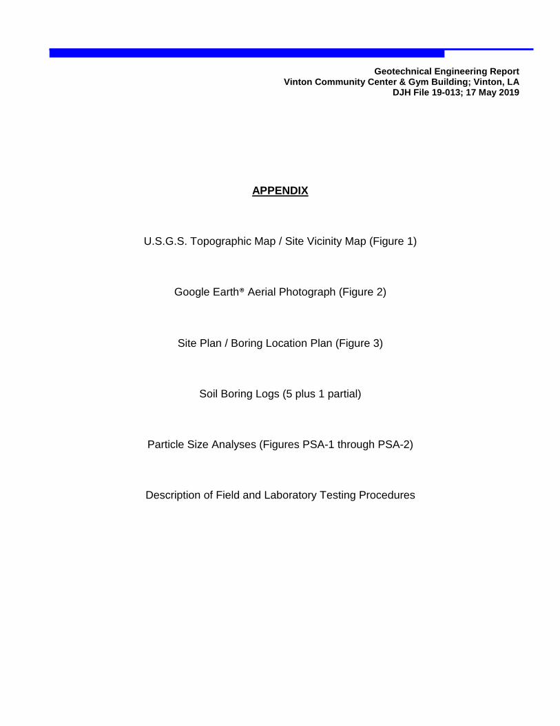
APPENDIX
U.S.G.S. Topographic Map / Site Vicinity Map (Figure 1)
Google Earth® Aerial Photograph (Figure 2)
Site Plan / Boring Location Plan (Figure 3)
Soil Boring Logs (5 plus 1 partial)
Particle Size Analyses (Figures PSA-1 through PSA-2)
Description of Field and Laboratory Testing Procedures

Daniel J. Holder, P.E., Inc. Vinton Community Center & Gym Building Project Engineer: DJH DJH File No. 19-013Vinton, Louisiana Drawn By: dan Date: 17 May 2019
2767 Scarborough Drive for Checked By:Lake Charles, LA 70615 Site Vicinity Map / (337) 274-4125 [email protected] Sulphur, Louisiana U.S.G.S. Topographic Map
Figure No. 1Vincent Shows Architects
Source: U.S.G.S. 7.5 Minute Topographic Map, 1999 (3-D TopoQuads, DeLorme)
Consulting Civil / Geotechnical Engineer

Daniel J. Holder, P.E., Inc. Vinton Community Center & Gym Building Project Engineer: DJH DJH File No. 19-013Vinton, Louisiana Drawn By: dan Date: 17 May 2019
2767 Scarborough Drive for Checked By:Lake Charles, LA 70615(337) 274-4125 [email protected] Sulphur, Louisiana Google Earth® Aerial Photograph
Figure No. 2Vincent Shows Architects
Source: Google Earth ® Aerial Photograph (dated 12/1/2017)
Consulting Civil / Geotechnical Engineer
Approximate Building Location

Daniel J. Holder, P.E., Inc. Vinton Community Center & Gym Building Project Engineer: DJH DJH File No. 19-013Vinton, Louisiana Drawn By: dan Date: 17 May 2019
2767 Scarborough Drive for Checked By:Lake Charles, LA 70615(337) 274-4125 [email protected] Sulphur, Louisiana Boring Location Plan
Consulting Civil / Geotechnical EngineerFigure No. 3
Vincent Shows Architects
Source: Site Plan Provided by Vincent Shows Architects
Site Plan /
Boring Locations by DJH, PE
B-1
B-2
B-4
B-5
B-3(3 attempts)
B-3E

Project: Vinton Community Center & Gym Building DJH File No: 19-013Location: 1615 Horridge Street Date Drilled: 4/15/2019
Vinton, Louisiana Logged By: Mike FogartyClient: Vincent Shows Architects Drilled By: D&L Geotechnical Serices
Sulphur, Louisiana Equipment: Simco SK-1 / Morooka Drill
Notes /
From Handheld GPS (approximate): N 30o 11.005' W 93o 34.776'
OtherTests
Boring Data Ground Water Data Notes / Other TestsBoring Advancement: First Encountered: 10' εf = Failure Strain
Dry Auger: After 20 Minutes: 5½'Rotary Wash:
Boring Abandonment:Boring Backfilled w/ Soil ST: Shelby Tube (ASTM D 1587)Cuttings Upon Completion SS: Split Spoon (ASTM D 1586) Soil Stratification is Approximate
Daniel J. Holder, P.E., Inc. 2767 Scarborough Drive (337) 274-4125Consulting Civil / Geotechnical Engineer Lake Charles, LA 70615 [email protected]
10
22
18
8
16
17
1516
20
2½ tsf
Gro
und
Wat
er
Qu
/ UU
(tsf
)
6
14
11
9
1.5Pl
astic
Lim
it, %
Dry
Den
sity
,
γd
(pcf
)
Atterberg Limits
54
ST 3 tsf
ST
ST 2¾ tsf
Liqu
id L
imit,
%
3
Dep
th (f
t)
Pene
trom
eter
(tsf
) or
SPT
(bpf
)
12
0.7 108 19 23Pl
astic
ity In
dex,
%
Moi
stur
e C
onte
nt,
w
(%)
SOIL BORING LOGBoring No. B-1
Field Tests
Description
Laboratory Tests
Sym
bol
Sam
ple
Type
Page 1 of 1
Sample Type:
0 - 10'n / a
25
2324
Boring Caved to 9' After 20 Mins.
21
ST 3¼ tsf
ST 2½ tsf
19
13
7
12
110 16 εf = 5.7%FILL - Stiff dark brown very SILTY CLAY (CL-ML), w/ roots - poorFirm dark brown CLAYEY SILT7 εf = 5.7%
Boring Completed at 10' Depth
(CL-ML) - poorFirm gray SANDY SILT (ML)Firm tan & gray SILTY CLAY (CL), w/large gray silt pockets - fairStiff light gray & tan SILTY CLAY (CL),w/ black oxides & gray silty crawfish hole
Soft gray SILTY CLAY (CL), w/ graysilty crawfish hole - poor
Project: Vinton Community Center & Gym Building DJH File No: 19-013Location: 1615 Horridge Street Date Drilled: 4/12/2019
Vinton, Louisiana Logged By: Mike FogartyClient: Vincent Shows Architects Drilled By: D&L Geotechnical Serices
Sulphur, Louisiana Equipment: Simco SK-1 / Morooka Drill
Notes /
From Handheld GPS (approximate): N 30o 11.006' W 93o 34.739'
OtherTests
Boring Data Ground Water Data Notes / Other TestsBoring Advancement: First Encountered: 10' εf = Failure Strain
Dry Auger: After 15 Minutes: 8'Rotary Wash:
Boring Abandonment:Boring Backfilled w/ Soil ST: Shelby Tube (ASTM D 1587)Cuttings Upon Completion SS: Split Spoon (ASTM D 1586) Soil Stratification is Approximate
Daniel J. Holder, P.E., Inc. 2767 Scarborough Drive (337) 274-4125Consulting Civil / Geotechnical Engineer Lake Charles, LA 70615 [email protected]
Sample Type:
0 - 15'n / a
202122232425
Qu
/ UU
(tsf
)
Moi
stur
e C
onte
nt,
w
(%)
Page 1 of 1
Dry
Den
sity
,
γd
(pcf
)
Boring Caved to 9' After 15 Mins.
2
11
89
SOIL BORING LOGBoring No. B-2
Field Tests
Description
Laboratory Tests
1Pl
astic
Lim
it, %
Gro
und
Wat
er
Atterberg Limits
Sym
bol
ST 2¾ tsf
ST
18
15
67
4
ST
5
2¾ tsf
ST 3 tsf
Plas
ticity
Inde
x, %
3
10
Liqu
id L
imit,
%
Dep
th (f
t)
Sam
ple
Type
Pene
trom
eter
(tsf
) or
SPT
(bpf
)
19
1716
1314
ST12
114
0.4 102
3 tsf
ST
2¾ tsf
3 tsf
ST 3¼ tsf
16 23 15 8 εf = 4.3%
0.7 109 18 εf = 5.7%
1.0
24 27 21 6 εf = 2.9%
0.4 96 26 εf = 4.3%
FILL - Firm mottled gray, light gray &tan very SILTY CLAY (CL) w/ roots - fairFirm gray to dark gray CLAYEY SILT(CL-ML), w/ roots - very poor
Firm gray w/ brown SILTY CLAY (CL),w/ lots of dark gray silt pockets - fair
gray very SILTY to SANDY CLAY (CL)
Boring Completed at 15' Depth
Firm tan & light gray SANDY CLAY (CL),
w/ lots of large black oxide nodulesFirm gray w/ reddish brown very SANDYCLAY (CL) to CLAYEY SAND (SC) - moist
- ditto
Firm laminated brown to tan & light

Project: Vinton Community Center & Gym Building DJH File No: 19-013Location: 1615 Horridge Street Date Drilled: 4/15/2019
Vinton, Louisiana Logged By: Mike FogartyClient: Vincent Shows Architects Drilled By: D&L Geotechnical Serices
Sulphur, Louisiana Equipment: Simco SK-1 / Morooka Drill
Notes /
From Handheld GPS (approximate): N 30o 10.989' W 93o 34.751'
OtherTests
Boring Data Ground Water Data Notes / Other TestsBoring Advancement: First Encountered: 5' εf = Failure Strain
Dry Auger: After 15 Minutes: 1'Rotary Wash:
Boring Abandonment:Boring Backfilled w/ Soil ST: Shelby Tube (ASTM D 1587)Cuttings Upon Completion SS: Split Spoon (ASTM D 1586) Soil Stratification is Approximate
Daniel J. Holder, P.E., Inc. 2767 Scarborough Drive (337) 274-4125Consulting Civil / Geotechnical Engineer Lake Charles, LA 70615 [email protected]
Moved Boring 50' East to B-3E
NA
1110
Boring Caved to 4½' After 15 Mins.
25
192021222324
Plas
tic L
imit,
%
Gro
und
Wat
er
18
15
45
14
1716
13
Qu
/ UU
(tsf
)
Moi
stur
e C
onte
nt,
w
(%)
Page 1 of 1
Sym
bol
89
6
Sample Type:
0 - 5'n / a
Liqu
id L
imit,
%
Dry
Den
sity
,
γd
(pcf
)
SOIL BORING LOGBoring No. B-3
Field Tests
Description
Laboratory TestsAtterberg Limits
Plas
ticity
Inde
x, %
7
Pene
trom
eter
(tsf
) or
SPT
(bpf
)
ST 1¾ tsf
Dep
th (f
t)
35 19 16
12
12
Sam
ple
Type
3
22ST 2 tsf εf = 10%
0.3 102 25 εf = 9.3%
FILL - Soft dark brown very SILTY CLAY (CL), w/ shells & roots - very poor
- ditto
0.5 101
FILL - Very soft gray SILTY CLAY toCLAYEY SILT (CL-ML) - wet
Boring Completed at 5' Depth
Note: Boring Encountered Refusaland Lost Drilling Water at 5' Depth.
Moved Boring 5' West, Ditto.
Moved Boring 12' South. Ditto.

Project: Vinton Community Center & Gym Building DJH File No: 19-013Location: 1615 Horridge Street Date Drilled: 4/15/2019
Vinton, Louisiana Logged By: Mike FogartyClient: Vincent Shows Architects Drilled By: D&L Geotechnical Serices
Sulphur, Louisiana Equipment: Simco SK-1 / Morooka Drill
Notes /
From Handheld GPS (approximate): N 30o 10.989' W 93o 34.743'
OtherTests
Boring Data Ground Water Data Notes / Other TestsBoring Advancement: First Encountered: 10' εf = Failure Strain
Dry Auger: After 15 Minutes: 6½' PSA = Particle Size Analysis (ASTM D 422)Rotary Wash: (refer to Figure PSA 1 in Appendix)
Boring Abandonment:Boring Backfilled w/ Soil ST: Shelby Tube (ASTM D 1587)Cuttings Upon Completion SS: Split Spoon (ASTM D 1586) Soil Stratification is Approximate
Daniel J. Holder, P.E., Inc. 2767 Scarborough Drive (337) 274-4125Consulting Civil / Geotechnical Engineer Lake Charles, LA 70615 [email protected]
SOIL BORING LOGBoring No. B-3E
Page 1 of 1D
epth
(ft)
Field Tests Laboratory Tests
Sym
bol
Sam
ple
Type
Pene
trom
eter
(tsf
) or
SPT
(bpf
)
Gro
und
Wat
er
Qu
/ UU
(tsf
)
Dry
Den
sity
,
γd
(pcf
)M
oist
ure
Con
tent
,
w (%
)
Atterberg Limits
Liqu
id L
imit,
%
Plas
tic L
imit,
%
Plas
ticity
Inde
x, %
Description
ST1 2¼ tsf2
ST3 3¾ tsf4
16
5678910111213141516171819202122232425
0 - 10'10' - 25' Boring Caved to 9½' After 15 Mins.
64 εf = 2.1%
Sample Type:
ST 3¾ tsf
ST 3½ tsf
ST 4¼ tsf
ST 3½ tsf
ST 3¾ tsf
ST 3¾ tsf
ST 4 tsf
PSA 10.9 107 19 23 7εf = 5.0%
1.8 111 17 εf = 10%
1.9 107 20 εf = 10%
0.4 96 27 29 21 8 εf = 2.9%
0.6 93 31 εf = 2.9%
1.6 80 41 102 38
Boring Completed at 25' Depth
FILL - Firm mottled dark brown & brown SILTY
CLAY (CL), w/ small shells & roots - poor
Firm dark gray CLAYEY SILT (CL-ML),w/ roots - poor
(CH), fatStiff dark gray & dark brown CLAY
- ditto
Stiff light gray w/ tan SILTY CLAY (CL),w/ gray silt streaks
- ditto, sandy
- ditto, w/ a large shell
Firm gray w/ reddish brown very SANDY
CLAY (CL) to CLAYEY SAND (SC),w/ black oxides
- ditto, gray & brown

Project: Vinton Community Center & Gym Building DJH File No: 19-013Location: 1615 Horridge Street Date Drilled: 4/12-15/2019
Vinton, Louisiana Logged By: Mike FogartyClient: Vincent Shows Architects Drilled By: D&L Geotechnical Serices
Sulphur, Louisiana Equipment: Simco SK-1 / Morooka Drill
Notes /
From Handheld GPS (approximate): N 30o 10.974' W 93o 34.770'
OtherTests
Boring Data Ground Water Data Notes / Other TestsBoring Advancement: εf = Failure Strain
Dry Auger: Rain 4/12. No Ground Water. PSA = Particle Size Analysis (ASTM D 422)Rotary Wash: (refer to Figure PSA 2 in Appendix)
Boring Abandonment:Boring Backfilled w/ Soil ST: Shelby Tube (ASTM D 1587)Cuttings Upon Completion SS: Split Spoon (ASTM D 1586) Soil Stratification is Approximate
Daniel J. Holder, P.E., Inc. 2767 Scarborough Drive (337) 274-4125Consulting Civil / Geotechnical Engineer Lake Charles, LA 70615 [email protected]
Sample Type:n / a Borehole Full of Water 4/15
Boring Stopped at 8' Due to0 - 15'
2425
181920212223
121314151617
67891011
345
Qu
/ UU
(tsf
)
Sam
ple
Type
Pene
trom
eter
(tsf
) or
SPT
(bpf
)
Gro
und
Wat
er
12
ST
SOIL BORING LOGBoring No. B-4
Page 1 of 1D
epth
(ft)
Field Tests Laboratory Tests
Sym
bol
DescriptionDry
Den
sity
,
γd
(pcf
)M
oist
ure
Con
tent
,
w (%
)
Liqu
id L
imit,
%
Plas
tic L
imit,
%
Plas
ticity
Inde
x, %
Atterberg Limits
ST 2½ tsf
3¼ tsf
ST 3 tsf
ST 4½ tsf
ST 3¾ tsf
ST 3¼ tsf
ST 2½ tsf
PSA 218 34 17 17
1.6 103 21 εf = 10%
2.2 114 18 40 19 21 εf = 10%
0.9 98 31 30 19 11 εf = 10%
0.6 97 28 εf = 4.3%
FILL - Firm tan & gray SILTY CLAY (CL) - poor
Firm dark brown very SILTY CLAY (CL),w/ roots - poorStiff light gray w/ tan SILTY CLAY (CL),
Firm light gray w/ tan very SANDY CLAY (CL) to CLAYEY SAND (SC)
- ditto, gray & reddish brown, moist
Boring Completed at 15' Depth
w/ calcium nodules- ditto- ditto, very stiff, w/ black oxides & light gray silt pockets
- ditto, sandy

Project: Vinton Community Center & Gym Building DJH File No: 19-013Location: 1615 Horridge Street Date Drilled: 4/12/2019
Vinton, Louisiana Logged By: Mike FogartyClient: Vincent Shows Architects Drilled By: D&L Geotechnical Serices
Sulphur, Louisiana Equipment: Simco SK-1 / Morooka Drill
Notes /
From Handheld GPS (approximate): N 30o 10.974' W 93o 34.738'
OtherTests
Boring Data Ground Water Data Notes / Other TestsBoring Advancement: First Encountered: 11' εf = Failure Strain
Dry Auger: After 20 Minutes: 4½'Rotary Wash:
Boring Abandonment:Boring Backfilled w/ Soil ST: Shelby Tube (ASTM D 1587)Cuttings Upon Completion SS: Split Spoon (ASTM D 1586) Soil Stratification is Approximate
Daniel J. Holder, P.E., Inc. 2767 Scarborough Drive (337) 274-4125Consulting Civil / Geotechnical Engineer Lake Charles, LA 70615 [email protected]
SOIL BORING LOGBoring No. B-5
Page 1 of 1D
epth
(ft)
Field Tests Laboratory Tests
Sym
bol
Sam
ple
Type
Pene
trom
eter
(tsf
) or
SPT
(bpf
)
Gro
und
Wat
er
Qu
/ UU
(tsf
)
Dry
Den
sity
,
γd
(pcf
)M
oist
ure
Con
tent
,
w (%
)
Atterberg Limits
Liqu
id L
imit,
%
Plas
tic L
imit,
%
Plas
ticity
Inde
x, %
Description
12345
εf = 10%
110 18 44678910111213141516171819202122232425
0 - 15'n / a Boring Caved to 9' After 20 Mins.
111 18 45 18 27
Sample Type:
ST 2¾ tsf
ST 3 tsf
ST 3½ tsf
ST 3¾ tsf
ST 4 tsf
ST 3¾ tsf
ST 3 tsf
1.5
1.9
0.5
17 27 εf = 10%
1.1 105 22 εf = 5.7%
101 24 εf = 3.6%
FILL - Firm brown SILTY CLAY (CL),w/ shells & large roots - poorFirm dark gray CLAYEY SILT (CL-ML),w/ roots - poorStiff gray w/ tan SILTY CLAY (CL), w/
(SC) to very SANDY CLAY (CL)
Firm gray w/ brown very SILTY to SANDY CLAY (CL)
Boring Completed at 15' Depth
gray silt streaks- ditto, w/ tan oxides & silt pockets- Very sandy, w/ a few black oxidesStiff gray & reddish brown very SANDYCLAY (CL) grading to CLAYEY SAND (SC)Firm reddish brown CLAYEY SAND

Sample Location: B-3E, 2' - 4'
Sample Description: Firm dark gray CLAYEY SILT (CL-ML), w/ roots - poor
PercentFiner
(Sieve) (mm.) By Wt.1½" 38.100
¾" 19.050
⅜" 9.500
#4 4.750
#10 2.000 100
#30 0.600 100
#50 0.300 100
#100 0.150 94
#200 0.075 70
0.029 64
0.019 58
0.015 56
0.011 52
0.008 48
0.006 44
0.005 41
0.004 39
0.003 36
Liquid Limit, LL: 23
Plastic Limit, PL: 16
Plasticity Index, PI: 7
19
Daniel J. Holder, P.E., Inc. Vinton Community Center & Gym Building Project Engineer: DJH DJH File No. 19-013Vinton, Louisiana Drawn By: dan Date: 17 May 2019
2767 Scarborough Drive for Checked By:Lake Charles, LA 70615 Particle Size Analysis(337) 274-4125 [email protected] Sulphur, Louisiana B-3E, 2' - 4'
Figure No. PSA-1Vincent Shows Architects
Particle Size Analysis (ASTM D 422)
ParticleSize
Atterberg Limits
Moisture Content, w:
Consulting Civil / Geotechnical Engineer
SandCoarse to Medium
0
10
20
30
40
50
60
70
80
90
100
0.0010.010.1110100
#200#100#50#30#10#4
U.S. Standard Sieve Size
GravelFine
Silt Clay
Particle Size (mm)
Perc
ent F
iner
(%)

Sample Location: B-4, 0 - 2'
Sample Description: Firm dark brown very SILTY CLAY (CL), w/ roots - poor
PercentFiner
(Sieve) (mm.) By Wt.1½" 38.100
¾" 19.050
⅜" 9.500
#4 4.750
#10 2.000 100
#30 0.600 100
#50 0.300 100
#100 0.150 96
#200 0.075 78
0.029 68
0.018 64
0.015 60
0.011 54
0.008 50
0.006 48
0.005 45
0.004 43
0.003 40
Liquid Limit, LL: 34
Plastic Limit, PL: 17
Plasticity Index, PI: 17
18
Daniel J. Holder, P.E., Inc. Vinton Community Center & Gym Building Project Engineer: DJH DJH File No. 19-013Vinton, Louisiana Drawn By: dan Date: 17 May 2019
2767 Scarborough Drive for Checked By:Lake Charles, LA 70615 Particle Size Analysis(337) 274-4125 [email protected] Sulphur, Louisiana B-4, 0 - 2'
Figure No. PSA-2Vincent Shows Architects
Particle Size Analysis (ASTM D 422)
ParticleSize
Atterberg Limits
Moisture Content, w:
Consulting Civil / Geotechnical Engineer
SandCoarse to Medium
0
10
20
30
40
50
60
70
80
90
100
0.0010.010.1110100
#200#100#50#30#10#4
U.S. Standard Sieve Size
GravelFine
Silt Clay
Particle Size (mm)
Perc
ent F
iner
(%)
Geotechnical Engineering Report Vinton Community Center & Gym Building; Vinton, LA
DJH File 19-013; 17 May 2019
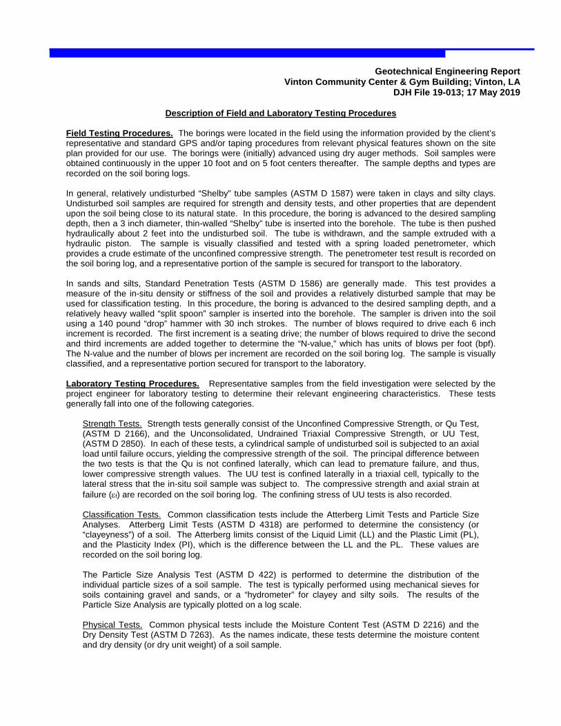
Description of Field and Laboratory Testing Procedures Field Testing Procedures. The borings were located in the field using the information provided by the client’s representative and standard GPS and/or taping procedures from relevant physical features shown on the site plan provided for our use. The borings were (initially) advanced using dry auger methods. Soil samples were obtained continuously in the upper 10 foot and on 5 foot centers thereafter. The sample depths and types are recorded on the soil boring logs. In general, relatively undisturbed “Shelby” tube samples (ASTM D 1587) were taken in clays and silty clays. Undisturbed soil samples are required for strength and density tests, and other properties that are dependent upon the soil being close to its natural state. In this procedure, the boring is advanced to the desired sampling depth, then a 3 inch diameter, thin-walled “Shelby” tube is inserted into the borehole. The tube is then pushed hydraulically about 2 feet into the undisturbed soil. The tube is withdrawn, and the sample extruded with a hydraulic piston. The sample is visually classified and tested with a spring loaded penetrometer, which provides a crude estimate of the unconfined compressive strength. The penetrometer test result is recorded on the soil boring log, and a representative portion of the sample is secured for transport to the laboratory. In sands and silts, Standard Penetration Tests (ASTM D 1586) are generally made. This test provides a measure of the in-situ density or stiffness of the soil and provides a relatively disturbed sample that may be used for classification testing. In this procedure, the boring is advanced to the desired sampling depth, and a relatively heavy walled “split spoon” sampler is inserted into the borehole. The sampler is driven into the soil using a 140 pound “drop” hammer with 30 inch strokes. The number of blows required to drive each 6 inch increment is recorded. The first increment is a seating drive; the number of blows required to drive the second and third increments are added together to determine the “N-value,” which has units of blows per foot (bpf). The N-value and the number of blows per increment are recorded on the soil boring log. The sample is visually classified, and a representative portion secured for transport to the laboratory. Laboratory Testing Procedures. Representative samples from the field investigation were selected by the project engineer for laboratory testing to determine their relevant engineering characteristics. These tests generally fall into one of the following categories.
Strength Tests. Strength tests generally consist of the Unconfined Compressive Strength, or Qu Test, (ASTM D 2166), and the Unconsolidated, Undrained Triaxial Compressive Strength, or UU Test, (ASTM D 2850). In each of these tests, a cylindrical sample of undisturbed soil is subjected to an axial load until failure occurs, yielding the compressive strength of the soil. The principal difference between the two tests is that the Qu is not confined laterally, which can lead to premature failure, and thus, lower compressive strength values. The UU test is confined laterally in a triaxial cell, typically to the lateral stress that the in-situ soil sample was subject to. The compressive strength and axial strain at failure (εf) are recorded on the soil boring log. The confining stress of UU tests is also recorded.
Classification Tests. Common classification tests include the Atterberg Limit Tests and Particle Size Analyses. Atterberg Limit Tests (ASTM D 4318) are performed to determine the consistency (or “clayeyness”) of a soil. The Atterberg limits consist of the Liquid Limit (LL) and the Plastic Limit (PL), and the Plasticity Index (PI), which is the difference between the LL and the PL. These values are recorded on the soil boring log. The Particle Size Analysis Test (ASTM D 422) is performed to determine the distribution of the individual particle sizes of a soil sample. The test is typically performed using mechanical sieves for soils containing gravel and sands, or a “hydrometer” for clayey and silty soils. The results of the Particle Size Analysis are typically plotted on a log scale. Physical Tests. Common physical tests include the Moisture Content Test (ASTM D 2216) and the Dry Density Test (ASTM D 7263). As the names indicate, these tests determine the moisture content and dry density (or dry unit weight) of a soil sample.