geotechnical, contaminated land and soil vapour review of ... · john philip piper . senior...
TRANSCRIPT

Geotechnical, Contaminated Land and Soil Vapour Review of the Environmental Effects Statement Edithvale and Bonbeach Level Crossings Confidential Privileged Communication Prepared for: Russell Kennedy Pty Ltd, on behalf of Kingston City Council Level 12, 469 La Trobe Street, Melbourne, Vic. 3000. 28 May 2018

Distribution
m16629_ees review_report_02.1.docx
i
Distribution
Geotechnical, Contaminated Land and Soil Vapour Review of the Environmental Effects Statement, Edithvale and Bonbeach Level Crossings 28 May 2018
Copies Recipient Copies Recipient
1 PDF
Mr Andrew Sherman Principal Russell Kennedy Pty Ltd, on behalf of Kingston City Council Level 12, 469 La Trobe Street, Melbourne, Vic. 3000.
1 PDF Senversa Project File
1 Reliance - This document has been prepared solely for the use of Russell Kennedy Pty Ltd, on behalf of Kingston City Council. No
responsibility or liability is accepted for any damages arising out of the use of this document by any third party. 2 Copyright and Intellectual Property – No portion of this document may be removed, extracted, copied, electronically stored or
disseminated in any form without the prior written permission of Senversa. Intellectual property in relation to the methodology undertaken during the creation of this document remains the property of Senversa.
3 Principles and Limitations of Investigation - This document is issued subject to the technical principles, limitations and assumptions provided in Section 4
4 Confidentiality – This report was prepared for Russell Kennedy Pty Ltd, on behalf of Kingston City Council and may contain confidential information. If you receive this report in error, please contact Senversa and we will arrange collection of this document.
Senversa Pty Ltd ABN: 89 132 231 380 Level 6, 15 William Street, Melbourne, VIC 3000 tel: + 61 3 9606 0070; fax: + 61 3 9606 0074 www.senversa.com.au
John Piper Senior Principal EPA appointed Auditor BE(Civil), MEngSci., FIEAust., NPER, RBP EC-1027

Contents
m16629_ees review_report_02.1.docx
ii
Contents
List of Acronyms ...................................................................................................................................................................... iii
1.0 Name and Address ....................................................................................................................................................... 1
2.0 Qualifications and Experience ..................................................................................................................................... 2 2.1 Qualifications ................................................................................................................................................................ 2 2.2 Accreditation ................................................................................................................................................................. 2 2.3 Professional Affiliations ............................................................................................................................................... 2 2.4 Employment History ..................................................................................................................................................... 2 2.5 Experience .................................................................................................................................................................... 3 2.6 Expertise ....................................................................................................................................................................... 3 2.7 Assistance .................................................................................................................................................................... 3
3.0 Introduction................................................................................................................................................................... 4 3.1 Proposed Works ........................................................................................................................................................... 4
Edithvale ......................................................................................................................................................................... 4 Bonbeach ....................................................................................................................................................................... 4
3.2 Scope of this Assessment ........................................................................................................................................... 4
4.0 Limitations of the Report ............................................................................................................................................. 5
5.0 Site Description, Hydrogeology & Geology ................................................................................................................ 6 5.1 Site Descriptions .......................................................................................................................................................... 6 5.2 Site Geology.................................................................................................................................................................. 6 5.3 Site Hydrogeology ........................................................................................................................................................ 8
6.0 Discussion .................................................................................................................................................................. 10 6.1 Horizontal Drain .......................................................................................................................................................... 10 6.2 Contamination issues................................................................................................................................................. 11 6.3 Settlement of the Adjacent Ground ........................................................................................................................... 12 6.4 Hydraulic Conductivity Tests ..................................................................................................................................... 14 6.5 Soil and Groundwater Vapours.................................................................................................................................. 14 6.6 Monitoring and Mitigation Measures ......................................................................................................................... 15
7.0 Conclusions and Recommendations ........................................................................................................................ 16
8.0 Declaration .................................................................................................................................................................. 17
9.0 References .................................................................................................................................................................. 18
Appendix A: Curriculum Vitae

List of Acronyms
m16629_ees review_report_02.1.docx
iii
List of Acronyms
Acronym Definition Acronym Definition
Environmental Geotechnical
ABC Ambient background concentration 1H:2V Slope Ratio of 1 Horizontal to 2 Vertical
ACL Added contaminant limit AHD Australian Height Datum
ACM Asbestos containing material AMG Australian Map Grid
AHD Australian Height Datum Base Course Upper Layer of the Pavement
AMG Australian Map Grid CBR California Bearing Ratio (%)
AS Australian Standard CFA Continuous Flight Auger
AST Above ground storage tank Cu Co-efficient of uniformity (D60 / D10)
ASS Acid Sulfate Soils CTCR Cement Treated Crushed Rock
ANZECC Australian and New Zealand Environment and Conservation Council D60 Diameter corresponding to 60% of the soil
being finer
BG Brighton Group DCP Dynamic Cone Penetrometer
BH Borehole EC Electrical Conductivity
BOD Biological Oxygen Demand Ed Design Action Effect
BPEM Best Practice Environmental Management FoS Factor of Safety
BTEX Benzene, toluene, ethylbenzene, xylenes fb Ultimate End Bearing Resistance
CIS Coode Island Silt fm,s Ultimate Shaft Resistance
CM Conceptual model GPS Global Positioning System
COC Chain of custody h’ D90 / D60
CoPC Contaminant of potential concern h’’ D90 / D15
CQAP Construction quality assurance plan HDPE High Density Polyethylene
CSM Conceptual site model kPa Kilopascal
CUTEP Clean up to the extent practicable LF Loading Factor
DNAPL Dense non-aqueous phase liquid mbgl Metres Below Ground Level
DO Dissolved oxygen MGA Map Grid of Australia
DSE Department of Sustainability and Environment MPa Megapascal
EC Electrical conductivity NATA National Association of Testing Authorities
EIL Ecologically based investigation level PLI Point Load Index
EES Environment Effects Statement Prime Application of a Primer to a Prepared Base

List of Acronyms
m16629_ees review_report_02.1.docx
iv
Acronym Definition Acronym Definition
EMP Environmental Management Plan Rd,g Design Geotechnical Strength
EPA Environment Protection Authority (Victoria) Sub-Base Course Lower Layer of the Pavement
ESL Ecological screening level Subgrade Foundation Material
GME Groundwater monitoring event TDS Total Dissolved Solids (salinity of water)
HIL Health-based investigation level UCS Unconfined Compression Strength
HSL Health screening level ys Characteristic Surface Movement
LEL Lower explosive limit φg Geotechnical Strength Reduction Factor
LFG Landfill gas
LNAPL Light non-aqueous phase liquid
LOR Limit of reporting
LTV Long term trigger values
m Metre
m3 Cubic metres
m AHD Metres Australian Height Datum
m bgl Metres below ground level
mg/kg Milligrams per kilogram
mg/L Milligrams per litre
MAH Monocyclic aromatic hydrocarbon
MoE Maintenance of Ecosystems
MSL Mean sea level
MW Monitoring well
NAPL Non aqueous phase liquids
NATA National Association of Testing Authorities
NEPC National Environment Protection Council
NEPM National Environment Protection Measure
NHMRC National Health and Medical Research Council
OCP Organochlorine Pesticides
OPP Organophosphate Pesticides
PAH Polycyclic aromatic hydrocarbons
PCB Polychlorinated Biphenyl
PCE Tetrachloroethene
List of Acronyms
m16629_ees review_report_02.1.docx
v
Acronym Definition Acronym Definition
PCR Primary contact recreation
PID Photo-ionisation detector
PSH Phase separated hydrocarbons
QA Quality assurance
QA Quaternary Aquifer
QC Quality control
RAP Remedial Action Plan
RPD Relative percentage difference
SEPP State Environment Protection Policy
SEPP PMCL State Environment Protection Policy (Prevention and Management of Contaminated Land)
SEPP GoV State Environment Protection Policy (Groundwaters of Victoria)
SEPP WoV State Environment Protection Policy (Waters of Victoria)
STV Short Term Trigger Values
SVOC Semi-volatile organic compound
SWL Standing water level
TCA Trichloroethane
TCE Trichloroethene
TDS Total dissolved solids
TKN Total kjeldahl nitrogen
TOC Total organic carbon
TPH Total petroleum hydrocarbons
TRH Total recoverable petroleum hydrocarbons
UTAF Upper Tertiary Aquifer Formation (Brighton Group)
UEL Upper explosive limit
UK EA United Kingdom Environment Agency
USEPA United States Environment Protection Agency
UST Underground storage tank
µg/kg Micrograms per kilogram
µg/L Micrograms per litre
VOC Volatile organic compound

List of Acronyms
m16629_ees review_report_02.1.docx
vi
Acronym Definition Acronym Definition
VRA Vapour intrusion Risk Assessment
VROM Netherlands Ministry of Housing
WHO World Health Organisation

Name and Address
m16629_ees review_report_02.1.docx 1
1.0 Name and Address
My name and address details are:
John Philip Piper
Senior Principal
Senversa Pty Ltd
Level 6, 15 William Street
Melbourne Vic 3000

Qualifications and Experience
m16629_ees review_report_02.1.docx 2
2.0 Qualifications and Experience
My qualifications, affiliations, accreditations and employment history are presented in the following sections. A copy of my Curriculum Vitae is presented in Appendix A.
2.1 Qualifications
My qualifications are:
• Bachelor of Engineering (Civil), University of Melbourne, 1976 • Master of Engineering Sciences, University of Melbourne, 1979
2.2 Accreditation
My accreditations are:
• Certified Practising Engineer • Registered Building Practitioner, Registration No. EC-1027 • Registered Engineer, Queensland • Environmental Auditor (Contaminated Land), EPA Victoria
2.3 Professional Affiliations
I am a Fellow of:
• Engineers Australia I am a member of:
• College of Civil Engineers – NPER-3, Reg. No. 407724 • Australian Geomechanics Society, Victoria • Australian Land and Groundwater Association (ALGA)
In addition, Senversa is a member of the Australian Contaminated Land Consultants Association (Vic)
2.4 Employment History My employment history is:
2018 – now Senversa, Senior Principal, Geotechnical, Environmental and Waste Engineering. 2011 – 2017 Cardno Victoria, Business Unit Manager / Senior Principal – Geotechnical,
Environmental, Hydrogeological Consulting. 2006 – 2011 Lane Piper, Director/ Senior Principal – Geotechnical, Environmental,
Hydrogeological Consulting. 1988 – 2006 Piper & Associates, Managing Director - Geotechnical & Environmental
Assessments. 1981 – 1987 SoilMech, Engineering Manager – Geotechnical Investigations, Melbourne. 1979 – 1981 SoilMech, Project Engineer – Geotechnical Investigations, Melbourne. 1977 – 1978 Golder Associates, Soils Engineer, Victoria.

Qualifications and Experience
m16629_ees review_report_02.1.docx 3
2.5 Experience
I have managed environmental, geotechnical, geological, hydrogeological, irrigation, geophysical and surveying projects incorporating multi-disciplined teams. I have specific expertise relating to slope stability for landslip and open cut mines, dams and embankments, multi- level basements, landfills, pavements, foundations, instrumentation and data acquisition systems, bridge abutments, pile groups and wastewater treatment plants. I have conducted and am conducting numerous environmental assessments including those for Environment Protection Authority Victoria (EPA Audits as well as being an EPA accredited auditor for environmental audits throughout Victoria.
With over 30 years’ experience, I have conducted geotechnical and environmental assessments throughout Australia and overseas.
2.6 Expertise
I have been involved in the investigation and design of deep excavations and multi–level basements for multi–storey buildings in Victoria. In addition, I have conducted geotechnical investigations for bridges, roads and other civil infrastructure. I have been involved in the assessment and review of slope stability for road and railway embankments and cuttings throughout Victoria and the New South Wales. I have assessed geotechnical issues for rail bridges at various sites. I have conducted many investigations for quarries that involved slope stability in Langwarrin, Lang, Maldon, Tallandoon, Scoresby, Geelong and Mt Eliza. In addition, I have undertaken a stability assessment of many slope failures including road and rail cuttings, creek embankments and hillsides. I have conducted investigations throughout Victoria and particularly in the Shire of Yarra Ranges, Mornington Peninsula Shire, Cardinia Shire, Colac – Otway Shire, Surf Coast Shire and other municipalities for both Councils and private companies and am approved to do landslip assessments in these Shires. I have been engaged by Mornington Peninsula Shire to peer review other consultant’s reports. I have completed a landslip susceptibility assessment for the entire Mornington Peninsula Shire which has been integrated into the Council EMO. I have lectured at RMIT on geotechnical matters, was an author of papers on slope stability at the Australian and New Zealand Geomechanics Conference in 1988 & 2012. I have received awards or been part of a team that received awards for projects in 1998, 2006, 2015 and 2016. I was the author of the Chapter on Quaternary sands in the Melbourne Area (Sand ridges and sheets) for Engineering Geology of Melbourne 1992.
I led the team involved in the unsuccessful bid for the Western Distributor project involving the geotechnical, contamination and hydrogeological assessment of the tunnels and portals. The portals had many similar issues facing these rail crossings.
I have conducted environmental assessments and statutory audits (S53X and S53V) for structures and developments throughout Victoria.
2.7 Assistance
I have been assisted in the preparation of this report by Mr Patrick Clarke, Senior Principal and Dr. Andrei Woinarski, Senior Associate at Senversa Pty Ltd.

Introduction
m16629_ees review_report_02.1.docx 4
3.0 Introduction
Senversa Pty Ltd was engaged by Russell Kennedy Pty Ltd on behalf of the Kingston City Council (Council) on 10th May 2018 to provide an expert opinion on specific issues in relation to the proceedings in the Panel Victoria and Advisory Committee in relation to the matter, relating to the proposed Edithvale and Bonbeach level crossings removal projects
3.1 Proposed Works
The two projects would involve the lowering of the Frankston railway line into two trenches under the roads, one at Edithvale Road, Edithvale and one at Station Street and Bondi Road, Bonbeach.
Edithvale
The Edithvale project is located predominantly within the railway reserve owned by VicTrack and extends from Lincoln Parade, Aspendale to Chelsea Road, Chelsea.
The trench would be constructed between Lochiel Avenue and Berry Avenue. It would be 1300 m in length, 14 m wide at the narrowest point, widening to 24m wide at the Edithvale Station. The rail track would be 8 m below the ground level at the lowest point at Edithvale Station and the maximum depth of excavation would be 14 m to allow for the underground infrastructure below the rail track to collect and divert rainwater from the trench. Decking above the rail trench would be provided for the new station building, car parking, and a sub-station. New pedestrian bridges would be constructed to provide access across the rail trench.
Bonbeach
The Bonbeach level crossing is also located predominantly within the existing rail reserve owned by VicTrack. The Bonbeach project extends from Chelsea Road, Chelsea to the Patterson River, Bonbeach.
The project involves the lowering of the rail track into a trench under Bondi Road while maintaining Bondi Road at the current road level. The trench would be constructed between Golden Avenue and The Glade. The trench would be 1200 m long and 14 m wide at the narrowest point and increase to 24 m at the new Bonbeach Railway station. Again, the rail track would be 8 m below the current ground surface at the lowest underground at Bonbeach Station and the maximum depth of excavation would be 14 m below current ground level to allow for the infrastructure to collect and divert rainwater from the trench.
Decking would be provided at about ground level for the new railway station building and car parking. New pedestrian bridges would be constructed for pedestrian access across the trench.
3.2 Scope of this Assessment
I understand the purpose of my assessment is to assist Council in satisfying itself that the work supporting the designs for the project is sound and the conclusions drawn are reasonable and appropriate in an email dated 10th May 2018.
Of particular concern is the potential mounding and lowering of groundwater levels associated with the project and related impacts including potential groundwater contamination movement. Specifically, the acknowledged mounding of the water table that is likely to occur on the hydraulically up-gradient side of the structure, particularly at the Edithvale site and the suggested engineering control to divert groundwater around the trenching structure and any opinion regarding the proposed groundwater diversion structure, recognising that the detail is not finalised as to its methodology.
This report will provide commentary on the issues of:
• Implications and practicality of groundwater re-distribution proposal. • Settlement issues as a result of construction. • Implications of the potential extraction of contaminated groundwater and soils. • Vapour intrusion risk.
Limitations of the Report
m16629_ees review_report_02.1.docx 5
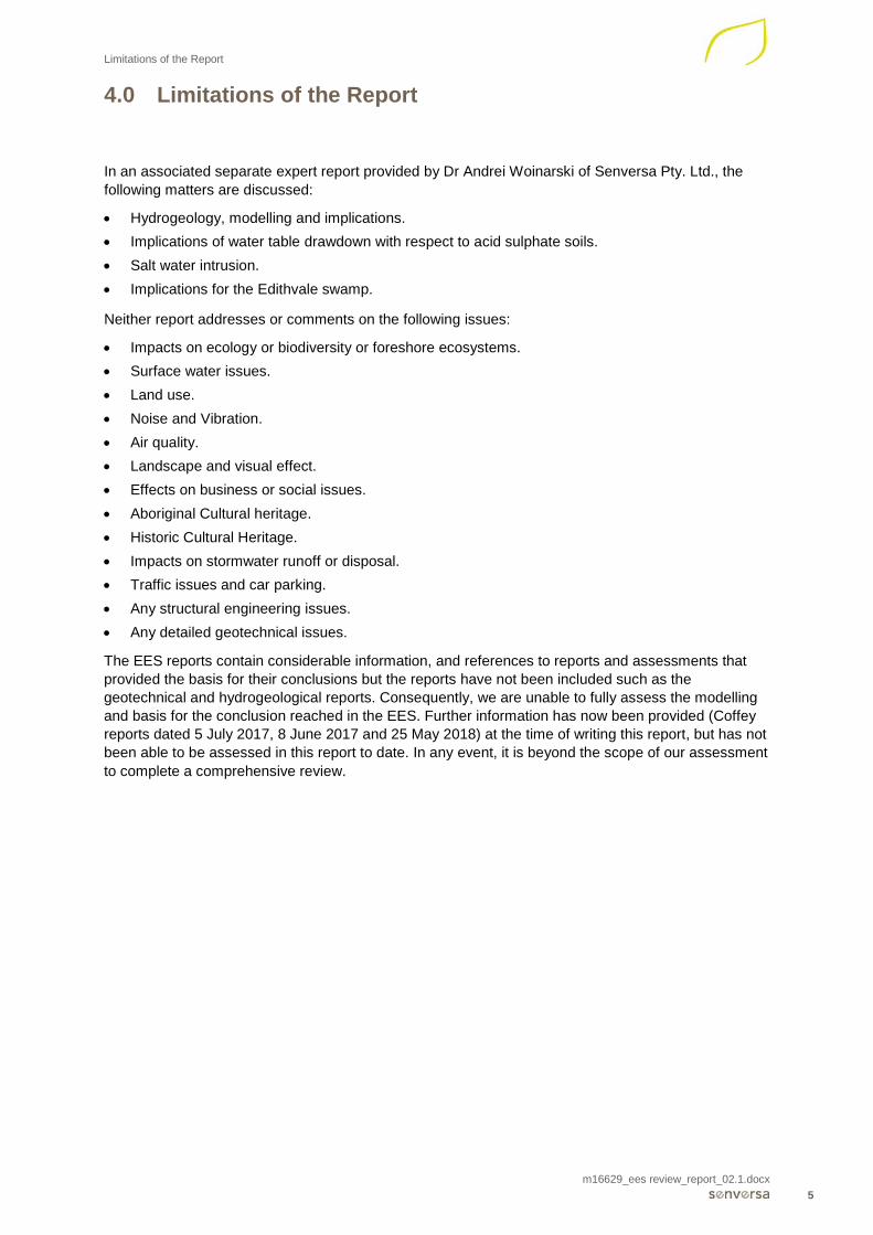
4.0 Limitations of the Report
In an associated separate expert report provided by Dr Andrei Woinarski of Senversa Pty. Ltd., the following matters are discussed:
• Hydrogeology, modelling and implications. • Implications of water table drawdown with respect to acid sulphate soils. • Salt water intrusion. • Implications for the Edithvale swamp.
Neither report addresses or comments on the following issues:
• Impacts on ecology or biodiversity or foreshore ecosystems. • Surface water issues. • Land use. • Noise and Vibration. • Air quality. • Landscape and visual effect. • Effects on business or social issues. • Aboriginal Cultural heritage. • Historic Cultural Heritage. • Impacts on stormwater runoff or disposal. • Traffic issues and car parking. • Any structural engineering issues. • Any detailed geotechnical issues.
The EES reports contain considerable information, and references to reports and assessments that provided the basis for their conclusions but the reports have not been included such as the geotechnical and hydrogeological reports. Consequently, we are unable to fully assess the modelling and basis for the conclusion reached in the EES. Further information has now been provided (Coffey reports dated 5 July 2017, 8 June 2017 and 25 May 2018) at the time of writing this report, but has not been able to be assessed in this report to date. In any event, it is beyond the scope of our assessment to complete a comprehensive review.

Site Description, Hydrogeology & Geology
m16629_ees review_report_02.1.docx 6
5.0 Site Description, Hydrogeology & Geology
5.1 Site Descriptions
The proposed railway trenches are located on the Frankston railway line and run parallel to the coast.
The groundwater is recharged by the wetlands and rainwater and flows generally towards the coast although at Bonbeach the groundwater flow is more north to south towards the Patterson River as well.
The conceptual hydrogeological model is shown in Figure No 1 below
Figure 1: Conceptual Model of Groundwater Flow (after Chapter 5 of EES)
5.2 Site Geology
Based on the geological map of the area, the surface geology (See Figure No 3, Cranbourne 1:63,360) indicates Quaternary dunes of siliceous and calcareous sands overlying a Quaternary alluvium of peaty clay swamp deposits often quite soft. In figure No 2, Leonard (1979) geological survey report of the region also indicates that the shallow Quaternary deposits of aeolian sands overlying clay alluvium exist to a shallow depth. The Quaternary deposits are underlain by the Tertiary sands and clays known as the Brighton Group. The Brighton Group is then underlain by the Tertiary-aged Fyansford Formation which primarily consists of glauconitic silts and clays.. In turn, the Fyansford Formation is underlain by the Tertiary-aged Older Volcanics, consisting of variably decomposed basalts and basaltic clays. The Older Volcanics are underlain at considerable depth by the Tertiary-aged Werribee Formation.

Site Description, Hydrogeology & Geology
m16629_ees review_report_02.1.docx 7
Figure 2: Geological Cross - Section (after Leonard, 1979)
Site Description, Hydrogeology & Geology
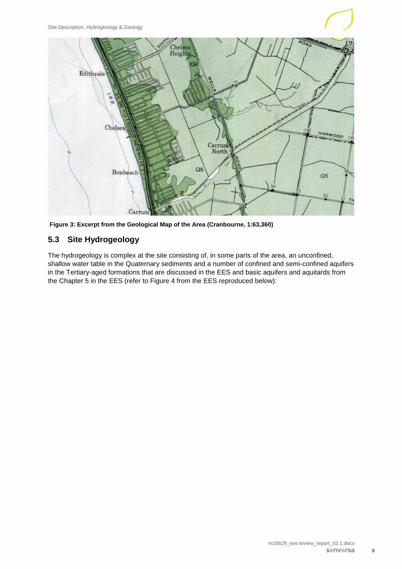
m16629_ees review_report_02.1.docx 8
Figure 3: Excerpt from the Geological Map of the Area (Cranbourne, 1:63,360)
5.3 Site Hydrogeology
The hydrogeology is complex at the site consisting of, in some parts of the area, an unconfined, shallow water table in the Quaternary sediments and a number of confined and semi-confined aquifers in the Tertiary-aged formations that are discussed in the EES and basic aquifers and aquitards from the Chapter 5 in the EES (refer to Figure 4 from the EES reproduced below):

Site Description, Hydrogeology & Geology
m16629_ees review_report_02.1.docx 9
Figure 4: Aquifer Cross - Section at the Study area (Excerpt from EES)

Discussion
m16629_ees review_report_02.1.docx 10
6.0 Discussion
From our review of the reports, the following issues have been identified for further comments and discussion. The issues discussed below are:
• The suitability and practicality of the horizontal drain. • Settlements of the adjacent Ground. • Hydraulic Conductivity tests • Soil Contamination Issues. • Monitoring and Mitigation Measures.
Subject to further information and clarification, some of the issues may or not be of concern .
6.1 Horizontal Drain
It is proposed to place a horizontal drain, at about a reduced level (RL) of -2 m Australian Height Datum (m AHD), around the rail trench to allow the mounded groundwater on the inland side of the trench to drain around the structure to the downstream side of the trench. This drain is only proposed at Edithvale as the groundwater direction at Bonbeach will result in less mounding and is not considered to be an issue by the LXRA. The purpose of the horizontal drain is to reduce the mounding on the upstream side of the trench and reduce drawdown of the water table on the downstream side of the trench. The horizontal drain is discussed in detail in Technical Report A Section 3. It is not clear to us if the groundwater modelling assumes that the discharge will be uniform. Friction losses in the pipe are included in the model (Technical report A Groundwater Section 4.1.1).
The writer has concerns about the effectiveness or unintended impacts of the proposed horizontal drain due to:
1. Its length around the structure, some 1300m at Edithvale.
2. Its lack of grade.
3. Due to the lack of grade, the potential for the pipe to ‘silt up’ over time, reducing its effectiveness.
4. No allowance for clogging is allowed for the model, although LXRA consider that it is unlikely. Our experience in the area indicates that iron deposition can occur and as the drain can be exposed to air, biological clogging as occur, particularly with the proposed fine apertures into the drainage pipes.
5. The potential for settlement of the piled wall or surrounding ground or issues occurring during installation resulting in low spots along the drainage pipe can occur, creating a ‘syphon’ effect.
6. On the downstream side of the pipe, concentrated discharge of groundwater into the water table on the hydraulically down-gradient side of the trench. Preferential flow paths could occur due to many features. For example, backfill around a sewer trench can provide a preferential flow path, rendering the wide distribution of lateral recharge on the downstream side of the trench wall ineffective. The writer is unaware if such a feature is existing or even proposed.
7. Registered and unregistered groundwater extraction bores known to occur in the area, can result in distortion of the groundwater flows in the area.
8. The drain will act as a conduit to transfer contaminated groundwater to the north and south and could result in more rapid migration or wider distribution of groundwater dissolved contaminants and light non-aqueous phase liquid (LNAPL) that may be present along the alignment of the proposed structure.
In our opinion and based on the information provided, the proposed single horizontal drain should be further assessed during the detailed design stage. If it is adopted, a detailed engineering analysis will be required and analysis by a pipeline engineer.

Discussion
m16629_ees review_report_02.1.docx 11
Moreover, there are some other solutions that could be considered or in conjunction with the proposed horizontal drain are:
1. Multiple horizontal pipes take groundwater from selected upstream areas and be discharged on the downstream side of the rail trench.
2. The construction of a syphon pipes through the wall, down and across the rail trench. Whilst noting the maintenance issues could be addressed by construction of access points.
3. Upstream extractive groundwater bores pumping around or across the rail trench to an injection bore on the downstream side. It is recognised that this is only a short-term solution.
The writer agrees that a review of the proposed design of this system be undertaken by an appropriately experienced professional with an appropriate technical support team to ensure that the adopted design is robust and meets the design requirements. Redundancy in the system is suggested to ensure that reliance upon a single approach is avoided. The writer does not suggest that there are no engineering solutions that will achieve the design objective.
It is noted that Ross McFarlane1 submission also raises issues about the effectiveness of the horizontal drain.
6.2 Contamination issues
The writer agrees with the EPA2 comments about the time to prepare necessary approvals particularly with respect to the management and disposal of soil with emerging contaminants such as PFAS. In addition, to create a stable floor within the trenches to enable the construction of the basal floor slab of the tanked underpass, there is likely to be a need to extract groundwater from within the railway trenches during construction to below the maximum excavation depth. Therefore, there is likely to be a need to dispose of an amount of groundwater as well as soil impacted by contaminants including PFAS.
The soil extracted during construction will need to be disposed offsite in accordance with EPA guidelines and if they contain PFAS may need discussion with the EPA for off-site disposal.
To date, there does not appear to be a comprehensive assessment of the contaminants from surrounding industrial activities, both current and historical, in the near vicinity of the rail trenches at each of the sites or has not been provided to date. The general nature of surrounding land uses indicates that there are potential sources of groundwater contamination. It is suggested that further assessment of potential sources and specific contaminants be undertaken and assess the impacts of the rail trenches on these contaminants. The EPA and LXRA has also indicated the need for further assessment.
As stated in the earlier section, the horizontal drains can be a conduit to transfer dissolved contaminants within the groundwater or LNAPL over a distance of up to 600m. If the groundwater horizontal drain works as proposed, the horizontal drain may transmit contaminants in the groundwater from a contamination plume to other areas that might not be currently impacted by the plume(s) to date. Furthermore, if there is a preferential flow path at the ends of the trench, there is the possibility of rapid flow to the beach or other properties not affected to date. It is suggested that further site-specific assessment be undertaken of the contaminants in the region, including the groundwater flow velocity and direction. In Technical Report C Page 147, it is stated for Edithvale that “it is almost certain that contaminant migration could occur as a result of altered groundwater flow paths, which would result in a localised, temporary and reversible loss of one or more beneficial uses of the environment”, but is proposed that the risk be reduced by the installation of a passive horizontal drain and other unknown measures. However, in certain circumstances, the drain could extend the groundwater plume.
Groundwater management, monitoring and mitigation measures are proposed by LXRA and will need to be included, See Section 6.6.
The “installation of the cut off walls” are proposed during construction to restrict groundwater inflow and allow the soils to be removed for the construction of the concrete base slab and railway
1 Macfarlane R., Edithvale Wetlands, undated Submission to Edithvale Bonbeach Level Crossing Removal 2 EPA Victoria, Edithvale – Bonbeach Level Crossing Submission, 1st May 2018

Discussion
m16629_ees review_report_02.1.docx 12
infrastructure. The LXRA comments that groundwater inflows both during construction into the trench will be about 600,000 litres per day, but could be between 50,000 and 1,900,000 litres based on a construction period for the excavation of 60 days. (Table 2, Technical Report A-Groundwater). However, in Technical Report C Section 9.2.3 that “the pile walls would prevent groundwater entering the excavated area” but between 20.8 and 21.7 ML of groundwater would need to be removed. The writer is unable to reconcile these differences in groundwater extraction unless it is considered that the groundwater includes porewater volumes in the soils. It is likely that much of this pore water will be removed with the soil removal rather than be all free groundwater as suggested in the EES. Groundwater will need to be extracted during construction and either injected hydraulically down–gradient or, if contaminated, will need to be treated and/or disposed to sewer. If the groundwater contains PFAS, early discussions with the EPA and the Water Authority may be required to organise disposal, potentially via a Trade Waste agreement.
It is proposed that the pile walls and the floor would be effectively impermeable (Technical Report A Groundwater Section 1.3.2). Whilst this can be achieved such that the structure is ‘tanked’ post construction, it is less likely during construction. However, any unexpected inflows could be addressed with the use of grouting during construction to reduce or eliminate any leaks through the piled wall and possibly grouting below the tanked floor prior to or during construction to reduce any up-flows.
6.3 Settlement of the Adjacent Ground
The EES considers settlement behind the rail trench retention system to occur from the reduction in the water level on the downstream side of the trench. For the Edithvale site, the maximum draw down is expected to be 1.5 m from the modelling, but in drought conditions, it is expected to fall to as low as sea level. It is understood that this could result in up to a 2 m drop of the water table. A much lesser fall is expected for the Bonbeach rail trench, provided that the predicted flow direction does not alter.
Whilst the writer agrees with this proposition of settlement from groundwater drawdown, there are additional items that could contribute to the settlements in addition to water drawdown. These are:
1. Lateral movement of the piled retention and cut-off wall, resulting in both horizontal and vertical movement behind the wall. Such movement is likely to occur if the retention system is designed for the ‘active’ condition. It is suggested that the retention system be designed for the ‘at rest condition’, if possible, or the lateral movements be reduced as far as practical.
2. Draw-down of the groundwater located within the Quaternary-aged aeolian silty sands and inter-dune swamp sediments can result in seepage forces and lead to densification of finer-grained sediments and subsequent settlement. It is likely that this effect has occurred in the past and so only minor settlement would be expected from this effect.
3. If construction of the retention system adopted the use of sheet piles or other driven piles, the vibrations can cause settlements of the ground. Such settlements are likely to be localised and only extend to within a few metres of the piling.
The writer agrees that the majority of the settlement will occur within the Quaternary soft clays. While the lower layers will also contribute depending on the area of the drawdown, these are likely to be very small. The thickness of the soft, compressible Quaternary layer will have major effect on the settlement. The LXRA has adopted a Young’s elastic modulus of 3MPa for the compressible layer, but no justification for this value is provided.
In support of the LXRA settlement predictions, the writer was involved in the construction of 3 test pads at the La Perouse housing development adjacent to the Patterson River and east of the Bonbeach rail trench between 2001 and 2006. (Piper & Associates, 2001 – 2005). The results of the settlements were measured over a period of 4 years. Whilst the loads are on the compressible layer are greater (~ 50 kPa) than the 1.5 m drop in water level expected from the groundwater draw down (up to 2m in a drought), the settlements are considerable for the test pads. Furthermore, in this instance the compressible layer thickness of 3 m is greater than the analysed thickness of 1.5 m adopted in the EES settlement predictions. It is understood that the thickness is typically 1.5 m at Edithvale and Bonbeach but can be up to 2 m. However, the writer has only been provided a few of the geotechnical borehole logs and no CPTu results to confirm these conclusions. Further information has been provided to the writer at the day of writing this report but at this time of writing this report, the writer has not had the opportunity to review the information provided..
The settlements of the 25 m x 25m test pads is shown below in Figure No. 5 overleaf.

Discussion
m16629_ees review_report_02.1.docx 13
Based on these settlement profiles, if the groundwater is drawn down by 1.5 m for a period of 90 days with a 1.5 m thick compressible layer, the expected settlement is 11mm which is similar to that predicted by the LXRA consultants. However, the settlements could be less if the compressible layer is over–consolidated or stiffer or thinner.1If the period of draw down is more or less, so the settlements will be more or less respectively. If the groundwater is drawn down for a period of 400 days, the settlement prediction based on the La Perouse results will increase. The LXRA settlement predictions do not appear to allow for the compression of the underlying layers but it is acknowledged that they will be very small and should not materially changed the settlement predictions.
The La Perouse settlements show that the majority of consolidation will occur fairly rapidly, so measures to prevent any groundwater level reduction is required within a relative short period. The monitoring and mitigation measures are required to be monitored closely during construction with any recharge bores installed and ready to be used if required. The monitoring of the groundwater is proposed and, if needed, the recharge bores be installed. If recharge bores are only installed when the trigger levels in the monitoring bores are exceeded, the time delay could result in additional distress to structures and underground services.
For a retaining wall designed for the active pressure, the settlements behind the wall are expected to be of up to 1 % of the depth of the excavation, decreasing to nil away from the structure at a distance of close to 2 times the depth of the excavation. For a 14 m deep excavation, the settlement will decrease but extend up to 28 m from the structure, and will decrease towards the edges of the rail trench as the excavation depth becomes less. Immediately behind the braced retention piles, the settlement can be expected to be up to 140 mm in the centre of the rail trench (Morgan J, 1989). If the structure can be designed for the ‘at rest condition’ or with additional bracing or tie backs, the settlements can be considerably reduced.
Settlement of the sands from seepage forces is likely to be small, but excessive settlements of the Quaternary sands have been known to occur in the sands in areas of fluctuating water table (Piper, 1992). Pile vibration from driven piles could increase these settlements but are likely to be quite localised and the logs provided indicate that the sands densities are very variable varying from very loose (N=3) to very dense (N=50). Some locations will settle more than others.
In conclusion and subject to detailed engineering design, the settlements behind the retention walls could be up to between 150 mm and 171 mm behind the retention piled wall and decrease to less than 10mm at a distance away from the structure. This distance will depend on a number of factors but the majority is likely to be less than 28m but some small settlement will occur up to 50m. The settlements will decrease towards the ends of the rail trench.
Many dwellings in this area may be designed for an S (slight) or M (moderate) site classification in accordance with AS2870.1 – 2011 or earlier versions, and therefore can be expected to accommodate a maximum characteristic surface movement of 20 mm and 40mm, respectively and a differential movement of about 10 mm and 20 mm respectively.
Dwellings would undergo distress if subjected to maximum settlements predicted close to the rail trench, but if dwellings are located at a distance away from the retaining walls by at least of 28m, the settlements will be much less and likely to not affect any dwellings unless the buildings are under stress. The writer is not aware if there are any structures within this vicinity. Furthermore, the settlements can be reduced to an acceptable level within the detailed design stage with appropriate engineering design. The settlements will depend on a number of factors, namely the distance of the dwelling or other structure sensitive to movement from the railway trench, the structural support, the bracing or retention system adopted, the depth, extent and period of groundwater draw down, the degree of over-consolidation and compressible of the Quaternary clay layer and the Brighton Group and the distance from the retention system.
It is suggested that further assessment and geotechnical modelling be undertaken during detailed design of the settlements behind the retention system to ensure that there is no distress to adjacent dwellings, structures, services or roads. However, based on the limited information provided to date and provided that there are no structures highly sensitive to settlement, it is unlikely that there will be any significant issues relating to settlement more than 28m from the structure and this distance potentially affected by settlements will decrease towards the north and south edges of the rail trench. It is acknowledged that the predicted settlements could be reduced to acceptable levels with appropriate design and construction

Discussion
m16629_ees review_report_02.1.docx 14
Figure 5: Settlement of the Test Pads, La Perouse Estate
6.4 Hydraulic Conductivity Tests
The groundwater report indicates that the hydraulic conductivity of the aquifers and aquitards were determined by performing both slug tests, rising/falling head tests and triaxial constant head permeability tests in the laboratory.
Whilst the slug tests are appropriate for the aquifers, it is also suggested that pump tests (if not already completed) be undertaken to assess the impacts of adjacent aquifers and also assess the impacts on the various aquifers.
There is a possibility that the aquitards permeability is being under-estimated, as the triaxial test will not assess the impacts of thin or fine, near horizontal sand layers. These thin sand layers can result in a horizontal hydraulic conductivity somewhat greater than the vertical permeability. The slug and falling head permeability tests can reflect this increase in the overall hydraulic conductivity
An assessment of the decreased vertical stress with the removal of the underlying soils within the railway trench can sometimes result in opening of the micro-fissures within the clay layers and increase the rate of flow upward. However, as the railway trench is to be ‘tanked’, it is unlikely to be an issue post construction.
The possibility of higher horizontal coefficient of permeability relative to the vertical coefficient of permeability should be assessed and included in the model (if not already done) and assess if an increase in the overall hydraulic conductivity in the aquitard will occur if the soils are to be partially de-stressed. These apply to the construction period only.
6.5 Soil and Groundwater Vapours
The writer was unable to identify any assessment of the risk to human health vapours from the ground or groundwater than are known to contain VOC’s and hydrocarbons including benzene, toluene, ethylbenzene, xylenes (BTEX) associated with petroleum contamination and other volatile solvents (e.g. chlorinated solvents). In Section 9.2.8 (Risk CL57) Technical Report C does discuss the issue of vapours from groundwater and soil and recommends the need for a targeted soil and groundwater investigation. A targeted soil and groundwater investigation would be based on a detailed review of current and historical activities on the sites and surrounding properties.
-350
-300
-250
-200
-150
-100
-50
00 200 400 600 800 1000 1200 1400
Settl
emen
t (m
m)
Days
Monitoring Rods Pad 3
Rod 4

Discussion
m16629_ees review_report_02.1.docx 15
The air quality assessment (Technical Report I) determines the potential impacts from construction activity (dust and vehicles), rail operations, and changed traffic movements from removal of the level crossings. Whilst the structure is tanked post construction, the risk to the health of the workers both during construction and access to the enclosed area below the track should be considered from the identified contaminants and if necessary, appropriate vapour venting and/or mitigation measures or occupation health procedures be included.
The writer agrees with the further assessment proposed and is not indicating that there is an unacceptable risk to human health and based on the provided data is to date the writer agrees that the risk to human health is unlikely but at least a qualitative vapour risk assessment should be undertaken with targeted soil vapour, soil and groundwater bores as proposed by LXRA.
6.6 Monitoring and Mitigation Measures
A Groundwater Management and Monitoring Plan (EPR GW3, GW2) is proposed to be developed with clear trigger levels. Any mitigation measures involving either extraction or injection of groundwater, it would be prudent to install a number of groundwater extraction and more critically, injection bores at the commencement of construction to ensure that any mitigation measures can be expedited within a short period and not have to wait for approvals, registration and installation delays. The settlements of the La Perouse trial embankments show that any delays in groundwater re-injection (if needed) can result in greater settlements.
Monitoring would be required for:
• Groundwater levels and contaminant concentrations in the surrounding bores. • Monitoring of groundwater and surface water discharged from the site. • Monitoring of the vapours and dust within the trenches during construction. • Assessment of the soils for offsite disposal (if not completed prior to excavation).

Conclusions and Recommendations
m16629_ees review_report_02.1.docx 16
7.0 Conclusions and Recommendations
None of the identified issues would prevent the construction of the level crossings at Edithvale or Bonbeach and can be all addressed during the detailed design. It is suggested that the horizontal drain proposal for Edithvale be further assessed for its practicality and ensure that there are no unintended consequences.
The writer agrees with the EPA and LXRA proposal regarding an independent reviewer and independent EPA Environmental auditor appointed under Section 53 of the EPA act be appointed to ensure that the further assessment, identified mitigation and design issues are carried through into the design and through construction to ensure that the monitoring and any mitigation measures are implemented within a suitable time frame.

Declaration
m16629_ees review_report_02.1.docx 17
8.0 Declaration
I, John Piper, have made all inquiries I believe are desirable and appropriate based on the readily available information and that no matters of significance that I regard as relevant have, to my knowledge, been withheld from this report.

References
m16629_ees review_report_02.1.docx 18
9.0 References
Leonard J.G., Preliminary Assessment of the Groundwater Resources in the Port Philip Region, Geological Survey report, No 66, 1979
Geological Survey, Cranbourne Geological Map, 1:63,360
Morgan J., Design Pressures and Lateral Movement Considerations for Temporary and Permanent Ground Support Systems, 1989.
Piper J., Quaternary Sands in the Melbourne Area (Sand ridges and sheets), Piper J.P., Engineering Geology of Melbourne, 1992

Appendix A: Curriculum Vitae
m16629_ees review_report_02.1.docx
Appendix A: Curriculum Vitae

John Piper - Enviro and Geotech May 18 Page 1 of 7
John P Piper Senior Principal
Qualifications & Certifications
B.E.(Civil), Melb
M.Eng.Sc., Melb
Career Profile
John is a Senior Principal Geotechnical Engineer. He commenced
as an engineer with Golder Associates and then Soilmech,
subsequently becoming engineering manager. In 1988, John began
Piper & Associates and over 20 years conducted a wide variety of
environmental and geotechnical assessments. In 2006, Piper &
Associates merged with Lane Consulting to form Lane Piper which
became Cardno Lane Piper in 2011.
He has a wide experience in all types of environmental
assessments, having worked on environmental site assessments
since 1992. His particular expertise is in environmental site
assessment, remediation of industrial and commercial sites, landfill
gas, wastewater treatment plants and landfills.
He is an EPA appointed environmental site auditor in Victoria and
the Northern Territory. He has worked on projects across Australia
and New Guinea. His clients have included local government,
government departments, private developers, investors, financiers,
land owners, mining and lawyers.
Expertise
Contaminated land assessments
Hydrogeology
Remediation
Landfill
Landfill gas and soil vapour assessment
Key Industry Sectors
Government – local and state
Private developers
Investors
Financiers
Land owners
Memberships
Member of the Organising Committee of the International
Conference of Environmental Geotechnics, 2014
Australian Land & Groundwater Association (ALGA)
Aust. Geomechanics Society (Vic)
Australian Contaminated Land Consultants Association (Vic)
Victorian Building Registration
National Association of Testing Authorities
Professional Training and Development
Environmental Auditor (Contaminated Land), EPA Vic,
Certified Practicing Engineer;
NATA Signatory.
Registered Building Practitioner;
Fellow of the Institute of Engineers
College of Civil Engineers - NPER-3.
Registered Engineer, Queensland (RPEQ)

John P Piper Senior Principal Geotechnical Engineer
John Piper - Enviro and Geotech May 18 Page 2 of 7
Project Experience
Significant Projects - Geotechnical
GEOTECHNICAL ADVICE FOR BUILDING FOUNDATIONS
21 -storey building, Southbank
10 storey apartment buildings, Abbotsford
Multi storey buildings, Richmond
Proposed large hospital extension, Bendigo
Large Potato Storage Shed, Smithton, Tasmania.
Redevelopment, Oak Towers Aged Care.
Many other multi storey developments in St Kilda Road and in the city
Numerous petrol service stations throughout Melbourne
Four storey block of apartments. Camberwell
6-storey block of apartments, Port Melbourne
8-storey block of apartments, Richmond.
4-storey car showroom and offices, Burwood
Tensioned membrane structures for schools and Melbourne University
A.W.I. Factory, Geelong.
Multi storey building with multiple level basement, Hawthorn
Multi – storey School of Management, Melbourne University
Site Classification for entire housing estates, Epsom Park, Berwick, Heatherton and others
Elderly Persons development, Point Cook and other Aged Care facilities
GEOTECHNICAL INVESTIGATIONS FOR MARINE AND HARBOUR WORKS
Bayside Development, Port Melbourne
Off Loading Ramp for Oil Rig, Barry’s Beach, Wharf Facilities, Corio.
Harbour Improvements, Portland.
Marina, Werribee.
Geotechnical and Contamination Assessment, Gelibrand Pier, Williamstown
SLOPE STABILITY AND LANDSLIDES
Landslip assessment and design of rehabilitation works of river embankment, Wastewater Treatment Plant, Wangaratta
Landslip Risk Assessment of Cliff faces, Black Rock and Sandringham
Assessment of Stability of Cliff Faces at Flinders, Sorrento, Dromana and others
Risk Assessment of Road Cuttings, Alexandra Parade, Toorak
Installation of Inclinometer Monitoring Bores, Sandringham & Black Rock
Installation and Monitoring of the Inclinometers and Reporting of Results throughout Mornington Peninsula Shire
Landslip Susceptibility Assessment for Mornington Peninsula Shire Council
Landslip Assessment and Remedial Works at Ballar Creek, Mt. Eliza, and Hearn Creek, Mt. Martha,
Stability Assessment of the Rehabilitation of very large Quarry, Geelong and smaller quarry at Tallandoon
Assessment & Stabilisation of the Tanti Creek Bank, Mornington
Housing developments within the Upper Yarra Ranges including giving evidence at VCAT
Stabilisation of a Road Embankment Failures at Mt. Eliza, Flinders, McCrae, Upper Beaconsfield, Emerald and Dromana
Assessment of Creek Embankments at a number of site in northern Victoria
Stabilisation of 40 m high Open Cut Mine, Maldon.
Failed Cuttings, Hallam and Cardinia
Failed High Wall, Scoresby.
Landslide, Portland.
Geotechnical assessment and provision of Expert Evidence in Supreme Court Action, Davey's Bay, Mt Eliza

John P Piper Senior Principal Geotechnical Engineer
John Piper - Enviro and Geotech May 18 Page 3 of 7
Project Experience
Stabilisation of Road Embankment, Flinders.
Assessments of numerous landslips in the Dandenong Ranges, Mornington Peninsula, San Remo and northern Victoria
BRIDGE FOUNDATIONS
Bridge Overpass of Hume Highway, Kalkallo
Pedestrian Bridge, Maribyrnong River
Maribyrnong Railway Bridge Abutment.
Road Bridge, Clifton Springs
Traralgon-Maffra Road Bridge.
South Eastern Arterial Road Link Bridges.
Other Bridges at Warrnambool and Kerang.
RECLAMATION AND LAND DEVELOPMENT
Complex housing development on soft alluvium involving wick drains, surcharge, monitoring and foundation investigation, Carrum
Rehabilitation and Landslip Assessment of Large Limestone Quarry, Fyansford
Assessment of proposed housing development and filling, housing development, Fyansford
Assessment of the implications of Filling of Sand Pit, Cheltenham & Oakleigh
Settlement of Filling beneath Tennis Courts, East Doncaster.
Stability Analysis of Reclaimed Land, Westgate Park.
National Golf Club and Access Roads, Cape Schanck.
Large housing development, Craigieburn, including l geotechnical and hydrogeological assessments of the site.
Large housing development, Kalkallo
Assessment of backfilling Quarry, Ferntree Gully
ROADS, RAILWAYS AND AIRPORTS
Numerous Pavements for sub-divisional roads and major arterial roads with Mechanistic Pavement Design for highly trafficked road,
throughout Melbourne and Victoria
Major Railway Stabling Yard, Calder Park
Rigid Pavement, Leongatha
Newport Training Centre.
Pavement Testing and Evaluation, Portland Airport.
Container Storage Pavements, Brooklyn.
Forensic investigation of pavements, Craigieburn, Pakenham, Werribee,
Geotechnical investigation and design of retaining walls for Failed Road, Upper Beaconsfield
Assessment of slope instability of roads, Upper Beaconsfield
Review of container terminal pavements, Botany Bay
TUNNELS AND SHAFTS
Fire Service Tunnel, Loy Yang.
Underground Station, Werribee.
Breakout Tunnel and Shaft, Werribee Trunk Sewer.
Investigation for many underground power and cable services in the inner Melbourne area
LARGE TANKS
Water Tanks, GMH - Port Melbourne.
Water Tanks, Bowater Scott, Box Hill.
Water Tanks, A.M.I., Port Melbourne.
Large Oil Tanks, BP, Spotswood
Water Supply Tanks, Birrarung Marr

John P Piper Senior Principal Geotechnical Engineer
John Piper - Enviro and Geotech May 18 Page 4 of 7
COMPUTER SOFTWARE & INSTRUMENTATION
Development of Inclinometer Program.
Development of Software for Data Acquisition System, Melton.
Craigieburn Dam, Tasmania.
Instrumentation of Penstock Well and Tunnel, Western Trunk Sewer.
Instrumentation of Refinery Catchment Lake, Worsley, W.A.
Instrumentation for Tailings Dam, Ok Tedi.
Automatic Data Logging System, Malmsbury.
Instrumentation of Pre-load embankment, Webb Dock
Significant Projects - Enviro Geotechnics
Geotechnical, Hydrogeological and Irrigation Assessments, Water Supply and Sewerage Works
Main Central Irrigation Pump Station, Mildura
Dam and Water Supply Bore, Marysville.
Large BOOT scheme for wastewater treatment at Echuca and Rochester, including treatment plant, large 2GL winter storage, and
pipeline
Large Water Supply Dam, Foster.
Ballarat to Bendigo 'Super' Pipeline
Wimmera Mallee Pipeline Leg
Macquarie Pipeline, Tasmania
Pipeline Design and QA Assessments in New Zealand
Pipeline Design Assessments in Gippsland and Merbein
Sewer Scheme, Cape Paterson.
Aerobic Sludge Lagoons, Kyabram, Horsham, Geelong, & Dandenong
Chandler Rd., Outfall Sewer.
Sewer Scheme, Metung
Water Scheme, Candowie.
Water Supply Dam, Dunkeld.
Effluent Storage & Elevated Storage Melton.
Investigation of Dam, Bulla & Bairnsdale.
Trunk Sewer, Alexandra.
Assessment of all dams for S-W Water
Dam surveillance of a number of dams in Victoria
Numerous sewerage treatment works throughout Victoria and southern NSW at Paynesville, Murchison, Boolarra, Bundalong,
Yarrawonga, Toora, Girgarre, Avenel, Violet Town, Swan Hill, Nyah West, Ouyen, Skipton, Hopetoun, Minyip, Mildura, Stanhope-
Rushworth, Tumut, Elmore, Lockington, Corryong and many others
LANDFILLS
Assessment of Landfill Liner, Deneliquin
Construction QA of landfill liner, Tullamarine
Concept Design of proposed Landfill, Dromana, McCrae
Assessment of site suitability for landfill, Mornington Peninsula Shire
Review of Liners, Sita Landfill Lyndhurst
Large Landfill, Bellarine.
CKD Landfill, Waurn Ponds
Boral Landfill, Deer Park
DAMS, WETLANDS AND EMBANKMENTS
Geotechnical and Hydrogeological Advice, Wetlands
Wetlands at numerous estates around Melbourne. Clients included developers, consultants and Melbourne Water
Farm Dams, Flinders, Bulla and many other farm dams in Victoria.

John P Piper Senior Principal Geotechnical Engineer
John Piper - Enviro and Geotech May 18 Page 5 of 7
Project Experience
Rehabilitation of Oval, Epsom Park
Many Wastewater Re-Use Schemes throughout Victoria
EXPERT EVIDENCE
Provision of geotechnical expert evidence for the slope stability of cliff face, Gunnerson vs State of Victoria, Mornington Peninsula
Shire Council
Geotechnical Expert Evidence for landfill, T. Love vs State of Victoria
Geotechnical Expert Evidence for Failed Building, Paynesville.
Geotechnical Expert Evidence on construction and slope stability of Pool, Mt Eliza for Mornington Peninsula Shire Council.
Geotechnical Expert Evidence of Fire Service Tunnel, Loy Yang
Attendance at VCAT on many building and slope stability issues.
Attendance at VCAT and expert evidence for drying beds, Mandalay Resources.
Significant Projects - Environmental
ENVIRONMENTAL & RISK ASSESSMENTS
Assessment and Remediation for Avendon Housing Estate resulting in 5 Environmental Certificates and 1 Statement of
Environmental Audit
Multi – Storey Apartment Building, Port Melbourne resulting in Statement of Environmental Audit
Multi-Use Building, Richmond –Environmental and Human Health Risk assessment
Apartments, Richmond resulting in a Certificate of Environmental Audit and review and inspection of vapour barrier and undertook a
vapour risk assessment
Numerous school sites around Melbourne involving Assessments, Remediation, Validation and Certificates of Environmental Audit
Environmental Assessments resulting in Audits of Proposed Housing Estates, throughout Melbourne, including Alphington,
Southbank, Deer Park, Cranbourne, Richmond and Lyndhurst
Risk Assessment for Multi-storey Development over former service station, Southbank
Many other environmental assessment (Phase 1 and 2) for previous service station sites, residential developments and industrial
sites
Environmental Due Diligence Assessment for future purchasers
Underground storage tank 'pulls'
Assessment of railway yards, Calder Park
Assessment and successful re-classification of soil for offsite disposal, Docklands
Assessment for a sub-division including landfill gas assessment
STATUTORY ENVIRONMENTAL AUDITS
S53V Audit for Service Station, with offsite hydrocarbon plume, N. Brighton for major oil company
S53V Audit for Wastewater Winter Storage, Mallacoota
S53V Audit for Oil Depot, Mildura and review of Clean Up Plan for major oil company
S53X Audit for proposed Crises Accommodation, St Kilda resulting in 2 Statements of Environmental Audit
S53X Audit for industrial development, Maribyrnong
S53X Audit for housing development Williamstown
S53X Audit of industrial complex including remediation of fluoride plume, with chlorinated hydrocarbon plumes, CUTEP's, Braybrook
with multiple Statements
S53X Audit for old Depot, Dandenong
S53X Audit for Service Station, St Albans
S53X Audit for Apartment Abbotsford including groundwater CUTEP
S53X Audit for Apartment Complex, North Melbourne
S53V Audit for Verification and Construction of Landfill, Waurn Ponds
S53V Audit for Landfill Construction, Bairnsdale
S53V Audit for Landfill Construction, Bunting Road, Braybrook
John P Piper Senior Principal Geotechnical Engineer
John Piper - Enviro and Geotech May 18 Page 6 of 7
Project Experience
S53V Audit for landfill gas, Wonthaggi
EXPERT SUPPORT FOR STATUTORY ENVIRONMENTAL AUDITS
Provided advice to the SA EPA on design and construction of clay liners
Provided geotechnical advice to EPA approved Environmental Auditor for the Environmental Audit of the clay lining for the landfill at
McIntosh Road, Sunshine
Provided geotechnical and civil engineering advice to Auditor for Victrack platform immobilised fill encapsulation structure
Provided advice for the removal and encapsulation of Cr (VI) contaminated soil and groundwater and support of the adjacent
buildings for Environmental Auditor, Montague Street, South Melbourne
Provided advice and assisted in the hydrogeological assessment for the S53V audit of the thickened tailings disposal proposal at
Hazelwood power station.
Provided leachability advice on the clay liner and tailings and environmental impact of the tailings disposal in the Audit to the new
storage at Loy Yang power station at Traralgon.
Advice for the audit of the clay capping of the Wingfield landfill, S.A.
Provided advice for the clay capping of a Cranbourne landfill
Assess the compliance of waste disposal system and in particular the drainage layer as part of a Supreme Court settlement for the
SA EPA
Provided expert advice on encapsulation structure for Victrack Spotswood, and Maribyrnong Defence
Provided a major role in the Audit team that assessed the capping of the landfill and compliance with the guidelines for the Wingfield
landfill for the SA EPA
LANDFILLS
Auditor landfill liner review and declaration, Waurn Ponds
Assessment of Landfill Liner, Deneliquin
Construction QA of landfill liner, Tullamarine
Proposed Landfill, Dromana, McCrae
Assessment of site suitability for landfill, Mornington Peninsula Shire
Review of Liners, Sita Landfill Lyndhurst
Large Landfill, Bellarine.
Bolinda Road Landfill.
Bio-sludge assessments
LFG assessment, Amstel Golf Course, Cranbourne.
Member of EPA consultative committee on landfills
REMEDIATION
Overall management of a $15 million involving the assessment and remediation of 50 contaminated sites for a major oil company
throughout Australia
UST Pull and Remediation of old service stations, Glen Waverley, Balwyn and others
Remediation of soil for burial grounds, Greenvale
Remediation of old fuel tank spillage, Abbotsford
Remediation of contaminated groundwater with MPVE and ISCO South Morang
Remediation of groundwater with MPVE,& ISCO, Footscray
Review of remediation scheme for service station LNAPL plume in response to EPA PAN, Ringwood E
Remediation field and laboratory trial, Pegasus Centre, Altona
Assessment and remediation of disused industrial and farm complex, including MPVE and ISCO, South Morang

John P Piper Senior Principal Geotechnical Engineer
John Piper - Enviro and Geotech May 18 Page 7 of 7
Awards & Publications
Stevensons Road Cranbourne Landfill - Lessons Learned and
Pragmatic Methodology for Landfill Gas Assessment and
Management in Australia" P.W. Gringinger, J. Piper, A.P. Lane
(2014), Proceedings of 7th International Congress on
Environmental Geotechnics, Melbourne, 10-14 November
2014. (Awarded best paper for that theme)
Cranbourne Landfill - Some Insights From an Intensely
Monitored Landfill Gas Case" P. Gringinger, A.P. Lane, J.P.
Piper (2013), Proceedings of Clean Up 2013, 5th International
Contaminated Site Remediation Conference, Melbourne, 15-19
September 2013.
Effect of Vibration on Pile Uplift Capacity”, Piper, J.P. (1981)
International Conference on Recent Advances in Geotechnical
Earthquake Engineering and Soil Dynamics, Missouri, USA.
"Analysis of Two Failed Excavated Slopes”, Piper, J.P. (1988)
Fifth Australasian Geomechanics Conference, Sydney
"GIS Assessment of Regional Landslide Susceptibility,
Mornington Peninsula Shire", (2012) Piper J.P. & Slade D.B.,
11th Australian and New Zealand Conference on
Geomechanics
ACSEV Design Excellence Award (1998), Geotechnical
Investigation And Analysis of Complex Piled Foundations For
Long Timber Arch Bridge Over The Maribyrnong River
Environmental Excellence Awards for Koolamara Waters and
Vaucluse estates

tel: + 61 3 9606 0070 fax: + 61 3 9606 0074 [email protected] www.senversa.com.au Level 6, 15 William Street, Melbourne, VIC 3000 Senversa Pty Ltd ABN 89 132 231 380