geotechnical challenges in construction of an …€¦ · storage tank, which is located ... design...
TRANSCRIPT

The HKIE Geotechnical Division Annual Seminar 2015
1 INTRODUCTION
Happy Valley was first developed as a race-course in 1846 on a piece of ‘swampy land in a valley’ and was
‘often affected by floodwater.’ The area around Happy Valley has long been prone to flooding problems.
During the major rainstorms in August 2000, April 2006 and June 2008, severe flooding occurred in Happy
Valley and adjacent areas including Sing Woo Road, Wong Nai Chung Road, Morrison Hill Road, Lap Tak
Lane and the Happy Valley Racecourse and the Recreation Ground.
In this area drainage improvement by upgrading the existing major stormwater drains is disruptive and very
difficult. It would involve open trenching in the busy main roads. To avoid serious disruption to the public
and to minimize complicated diversion of the underground utilities, an underground storage tank was
proposed.
The underground storage tank will temporarily store part of the stormwater collected from the upstream
catchment. The addition of the storage tank would enable the drainage system to handle major rainstorm
events effectively, thus minimizing flooding problems in the area. The stormwater will subsequently be
discharged via pumps and gravity drains to the outfall once the stormwater flow volume in the existing drains
has subsided.
The Contract was awarded to Chun Wo Construction & Engineering Co., Ltd. (Chun Wo) in September
2012 who submitted, and obtained approval for a cost-saving design with raft foundations and under-drainage
system. The permanent and temporary works design is by Black & Veatch Hong Kong Limited (BV HK).
This contract is one in the initial batch of Government contracts to use New Engineering Contract (NEC)
instead of the traditional General Conditions of Contract (GCC). As a part of this contract, an Independent
Geotechnical Engineer (IGE), ONLYgeotechnics Ltd, was appointed to provide advice and assistance to the
Client, DSD, in their supervision and control with regard to geotechnical aspects of the contractor’s work. To
Geotechnical Challenges in Construction of an Underground
Stormwater Storage Scheme in Happy Valley
W.H. Luk, C.L. Leung & C.Y. Lam Drainage Services Department,
the Government of Hong Kong SAR
M.S. Hendy, S.S. Fang & J. Premchitt ONLYgeotechnics Limited, Hong Kong
K.H. Lum Black & Veatch Hong Kong Limited, Hong Kong
ABSTRACT
Happy Valley Underground Stormwater Storage Scheme (HVUSSS) is under construction by
Chun Wo Construction and Engineering Company Limited and supervised by the Drainage
Projects Division of the Drainage Services Department, the Government of the HKSAR,
supported by an Independent Geotechnical Engineer. The Scheme includes construction of a
storage tank, which is located below the existing football pitches at Happy Valley. Phase One
work including the southern portion of the scheme was constructed to a very tight programme.
As a part of this work, temporary excavations supported by strutted sheet pile wall have been
carried out in close proximity to sensitive structures. Soil-Structure Interaction modelling was
conducted as a part of the design of temporary support for sheet pile wall. The project requires
extensive geotechnical instruments monitoring with daily feedback to the Project Manager,
Contractor, temporary works designer and the IGE. This paper presents the geotechnical
challenges of the Excavation and Lateral Support works of the Phase One project (include 30,000
m3 storage tank, pump house, box culvert, etc.) together with description of notable events during
construction.
73
The HKIE Geotechnical Division Annual Seminar 2015
ensure timely control and minimizing any damages during Excavation and Lateral Support works,
geotechnical instruments monitoring was carried out with daily feedback to the Project Manager (the Engineer
as referred in GCC), Contractor, temporary works designer and the IGE.
2 SITE LOCATION
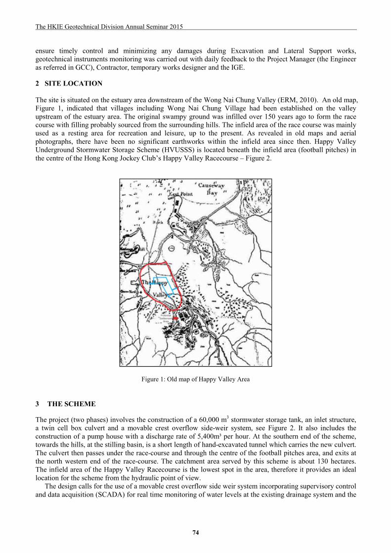
The site is situated on the estuary area downstream of the Wong Nai Chung Valley (ERM, 2010). An old map,
Figure 1, indicated that villages including Wong Nai Chung Village had been established on the valley
upstream of the estuary area. The original swampy ground was infilled over 150 years ago to form the race
course with filling probably sourced from the surrounding hills. The infield area of the race course was mainly
used as a resting area for recreation and leisure, up to the present. As revealed in old maps and aerial
photographs, there have been no significant earthworks within the infield area since then. Happy Valley
Underground Stormwater Storage Scheme (HVUSSS) is located beneath the infield area (football pitches) in
the centre of the Hong Kong Jockey Club’s Happy Valley Racecourse – Figure 2.
Figure 1: Old map of Happy Valley Area
3 THE SCHEME
The project (two phases) involves the construction of a 60,000 m3 stormwater storage tank, an inlet structure,
a twin cell box culvert and a movable crest overflow side-weir system, see Figure 2. It also includes the
construction of a pump house with a discharge rate of 5,400m³ per hour. At the southern end of the scheme,
towards the hills, at the stilling basin, is a short length of hand-excavated tunnel which carries the new culvert.
The culvert then passes under the race-course and through the centre of the football pitches area, and exits at
the north western end of the race-course. The catchment area served by this scheme is about 130 hectares.
The infield area of the Happy Valley Racecourse is the lowest spot in the area, therefore it provides an ideal
location for the scheme from the hydraulic point of view.
The design calls for the use of a movable crest overflow side weir system incorporating supervisory control
and data acquisition (SCADA) for real time monitoring of water levels at the existing drainage system and the
74

The HKIE Geotechnical Division Annual Seminar 2015
tidal levels at the outfall to control up and down movement of the weir automatically. This innovative and
intelligent design would reduce the volume of the storage tank by 30% and save electricity consumption up to
60%. The pumping station will be remotely monitored and controlled, with outgoing data stream of water
levels, status of pumps and penstocks, any equipment failure etc.
Figure 2: Key features of the HVUSS
4 DESIGN SCHEME
The original design for foundations of the scheme indicated that pre-bored H-piles socketed into bed rock
would be required. Due to the lighter unit weight of the storage tank than that of the existing ground, the
foundation was designed to be capable of resisting the buoyant force. The Contractor proposed a cost saving
design using a raft foundation with subsoil drainage system including a cut-off wall (BV, 2012). The system
would maintain groundwater level to below a limit by conveying any excess groundwater through a drainage
blanket to be discharged or re-used. A series of groundwater monitoring points was installed along the
perimeter of the storage tank within the groundwater cut-off wall. An array of pressure relief wells was
constructed at the base slab of the storage tank as a part of emergency relief of any high groundwater pressure
within the groundwater cut-off wall. This alternative design was agreed and adopted.
The storage tank itself is a large concrete structure, L-shaped in the overall layout plan as viewed from
above, see Figure 3. The structure is some 7 metres deep. It is built in two phases according to the layout of
the existing football pitches in order to maintain the use of some of the football pitches throughout the
construction duration. The design allowed for soil cover of up to 800 mm thick on top of the storage tank for
re-turfing works, which would enhance the resistance to the uplifting force.
The alignment for the stormwater culvert (Figure 3) runs parallel to the storage tank and lies between the
“LCSD building” and the main excavation. The building is 2-storey LCSD changing rooms building for the
users of the infield’s sports facilities, with the large Diamond Vision Screen mounted on its roof. In order to
minimize disturbances to nearby sensitive structures, the construction sequence required early completion of
the stormwater culvert, before the start of the excavation for the adjacent storage tank. This would minimise
the effect of the main excavation on ground movements at the LCSD building.
5 GROUND CONDITIONS Ground investigations were conducted in the 1990’s associated with development of the Hong Kong Jockey
Club. Later, a two phased ground investigation was carried out in 2010 for USSS by DRILTECH comprising
36 drillholes, 1 trial pit, 30 inspection pits and 6 trial trenches and 8 GCO probes. A third phase of
75

The HKIE Geotechnical Division Annual Seminar 2015
investigation was undertaken following award of the contract to verify the design parameters for the cost
saving design. This included an additional 10 boreholes and 10 Cone Penetration Tests (CPTs).
Overall the investigation showed the ground conditions comprise several metres of sandy clayey Fill
underlain locally by Pond/Marine Deposits (soft clays) up to 5 metres thick. Below the soft clays is Alluvium
of predominantly sandy silty CLAY but locally clayey silty SAND up to 17m thick. The underlying bedrock is
Granite. Figure 4 is a summary of soil strata, and a section through the site is shown in Figure 5. Geotechnical
properties of the strata are summarized in Figure 6.
Figure 3: Underground Tank and Culvert Alignment
Figure 4: Summary of Soil Strata Extracted from GEO (2012)
Review of the Phase I ground investigation results indicated that the superficial deposit comprises fill,
pond deposit, estuary deposit, marine deposit, alluvium and colluvium. The fill layer is found in all drillholes
and the trial pit/trial trenches with a maximum thickness of 4.20m in drillhole BH15, which composed mainly
of clayey silty sand and sandy clayey silt with some angular gravel and occasional cobbles of rock fragments
76

The HKIE Geotechnical Division Annual Seminar 2015
materials. Alluvium is found in all drillholes with a maximum thickness of 16.20m in drillhole BH1, locally
interbedded with pond deposit in BH3 and IBH2, interbedded with estuary deposit in BH6 to BH8, BH11 and
IBH2 and interbedded with marine deposit in BH10 and IBH2, which composed mainly of sandy silty clay
and clayey silty sand with gravel materials. Colluvium is found in drillhole BH4 only with a thickness of
approximately 9.20m, which composed mainly of clayey silty sand with gravel materials. The distribution of
subsoil strata is rather complex, hence in model simulation a large number of different strata has to be
included and their thicknesses vary greatly in different vertical sections.
Figure 5: Ground Profile at Section A-A of Figure 3
Figure 6: Geotechnical Properties of Various Soil Strata Extracted from GEO (2012)
Groundwater monitoring records show the highest level of groundwater to be close to ground level ~
+5mPD with a lower level at around +2.9mPD. The water table generally follows the ground profile which
falls gently towards the north west.
6 SOIL-STRUCTURE INTERACTION MODELLING As a part of the design for the Excavation and Lateral Support system, extensive Soil-Structure Interaction
modelling was carried out. Two dimensional finite element analyses were conducted using the BD approved
program PLAXIS version 9.02. Plane strain conditions are assumed. The analyses’ results were used to
assess the ground movements at and around the excavation face, the sheet pile and the nearby sensitive
structures. Initial analyses were conducted from early 2013. Five vertical sections within the area under
construction were analysed, see Table 1. The analysis for each of the sections was performed through all the
construction stages (phases) relevant to section from start to finish in a step by step procedure. The number of
77
The HKIE Geotechnical Division Annual Seminar 2015
ground strata included in the analysis varied from 24 to 10 depending on the section considered. Additionally,
relevant structural elements were also included, such as sheet pile wall, concrete walls and slabs of storage
tank, box culvert and LCSD Building. The total numbers of construction stages, time steps, ground strata and
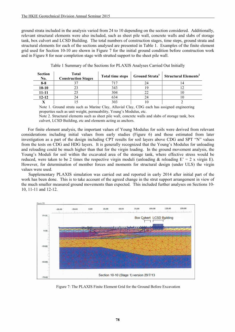
structural elements for each of the sections analysed are presented in Table 1. Examples of the finite element
grid used for Section 10-10 are shown in Figure 7 for the initial ground condition before construction work
and in Figure 8 for near completion stage with strutted support to the sheet pile wall.
Table 1 Summary of the Sections for PLAXIS Analyses Carried Out Initially
Note 1. Ground strata such as Marine Clay, Alluvial Clay, CDG each has assigned engineering
properties such as unit weight, permeability, Young’s Modulus, etc.
Note 2. Structural elements such as sheet pile wall, concrete walls and slabs of storage tank, box
culvert, LCSD Building, etc and elements acting as anchors.
For finite element analysis, the important values of Young Modulus for soils were derived from relevant
considerations including initial values from early studies (Figure 6) and those estimated from later
investigation as a part of the design including CPT results for soil layers above CDG and SPT “N” values
from the tests on CDG and HDG layers. It is generally recognized that the Young’s Modulus for unloading
and reloading could be much higher than that for the virgin loading. In the ground movement analysis, the
Young’s Moduli for soil within the excavated area of the storage tank, where effective stress would be
reduced, were taken to be 2 times the respective virgin moduli (unloading & reloading E’ = 2 x virgin E).
However, for determination of member forces and moments for structural design (under ULS) the virgin
values were used.
Supplementary PLAXIS simulation was carried out and reported in early 2014 after initial part of the
work has been done. This is to take account of the agreed change in the strut support arrangement in view of
the much smaller measured ground movements than expected. This included further analyses on Sections 10-
10, 11-11 and 12-12.
Figure 7: The PLAXIS Finite Element Grid for the Ground Before Excavation
Section No.
Total Construction Stages Total time steps Ground Strata1 Structural Elements2
8-8 37 717 24 14
10-10 23 343 19 12
11-11 25 304 22 10
12-12 24 634 24 10
X 15 303 10 2
78

The HKIE Geotechnical Division Annual Seminar 2015
The total ground settlement around an excavation comprises two part, settlement due to wall deflection
and that due to groundwater drawdown. PLAXIS analysis was able to simulate the wall deflection and the
associated ground settlement as well as the groundwater drawdown and the related settlement. For the area
around the LCSD Building the results from PLAXIS for the maximum total ground settlement is 26 mm. The
maximum estimated at the most critical high mast for lighting (out of the 10 masts) is about 22 mm. The
range of possible maximum settlements at the edge of race track was estimated to be from 5 to 14 mm. For 10
m wide zone surrounding the outside of the sheet pile cut-off wall, the estimated ground settlement is more
than 25 mm. Part of the jogging path and part of paved area at the east of the LCSD Building are in this zone
and could be affected. It is considered that the impact to the race track and the area east of LCSD Building are
much less critical than the impact to LCSD Building itself and the high masts.
Figure 8: The PLAXIS Finite Element Grid for the Excavated Ground with Strutted Support (Stage 21)
It is considered that the results from PLAXIS simulation are within the settlement limit generally adopted
for settlement control at or near structures. Therefore the Action Level was set at 25 mm, with Alarm and
Alert Levels set at 20 and 10 mm respectively.
7 GEOTECHNICAL CHALLENGES The construction works started from September 2012, and reached substantial completion of Phase One by
March 2015. The works commenced with construction of the pump house followed by excavation for the
storage tank. As the excavation progressed, temporary support is provided by installation of sheet piles using
a “silent piler” to minimize any noise impact to the public in the vicinity. Thickness of the soft layer is critical
in the control of movements during the work, and the thickness contour is shown in Figure 9. The progress of
work up to May 2014 is illustrated in Figure 10.
The cost saving design requires the sheetpile wall around the storage tank to act as groundwater cut-off
wall as a part of permanent work to minimize the water pressure under the tank. The sheetpile wall has to
perform this function well or else there could be a high uplift force, nevertheless there is a contingency
measure for such an event by activating the relief wells. Pumping test for demonstrating water tightness of the
sheetpile wall was conducted. Although some seepage was observed from the sheetpile wall, the amount is
considered small and well below the limit allowed for in the design.
The design also requires excavation of about 7 metres of the superficial deposits, with much of it below the
level of the ground water table. The LCSD building with Diamond Vision Screen on top, and the high mast
supporting the flood lighting (> 20 m high) are both quite close to the excavation. According to ArchSD as-
built drawings, the building is founded on a raft footing, a hollow box structure embedded about 1.6m below
ground (BV, 2012). The hollow box reduced the load on the soil strata below. The high mast (visible in
79

The HKIE Geotechnical Division Annual Seminar 2015
Figure 12) poses a particular challenge. It is founded on shallow spread footing, size 4.3m x 4.3 m at about 1.6
m depth, and only a few metres from the excavation. Local softening due to heavy rain exacerbated the
potential movement and will be discussed later. The challenge for the construction was to have adequate
excavation support system, with control on construction sequence, and continuous monitoring / alert system
for on-going detection of any excessive movement and timely remedial action.
Figure 9: Contours of Soft Deposits Figure 10: Phase One Construction in Progress May 2014
The design of the Excavation and Lateral Support is a typical arrangement with multiple struts required as
excavation proceeds. One of the particular challenges arose at the sheet pile wall immediately in front of the
LCSD building. This is the most sensitive area but made more complex because of the location of the box
culvert between the storage tank and the building. Programme requirements dictated early construction of the
box culvert between the pair of sheet piles shown in Figure 11. The design indicated that some movement of
the LCSD building and area to the east of the building would occur during trenching and installation of the
box culvert and this movement would be further developed during excavation for the adjacent stormwater
storage tank. As a cost-effective alternative for extensive ground treatment works, pre-loading of the struts
was introduced to mitigate the predicted movement of the building. The lateral support work in progress is
shown in Figure 10.
(a) (b)
Figure 11: The Arrangement for Excavation and Support in Two Areas
80

The HKIE Geotechnical Division Annual Seminar 2015
8 INSTRUMENTATION AND MONITORING
Assessment of the results from the finite element modelling could be made by comparing the results with the
measured movements from instrument monitoring including those on sensitive facilities located close to the
race course compound. This was done based on the monitoring report of cumulative readings of all
instruments up to the end of February 2015. For ground settlement, it is mostly below Action Level of 25 mm,
with only about 10% of ground settlement markers (19/189) having settlement readings exceeded the level.
The percentage is also relatively low, about 18%, for building settlement markers (12/68), and 5% for tilt
markers (4/83). Most other readings show little movements. Apart from SSI modelling, other factors during
construction have to be taken account of, such as the mis-match in the sequences of excavation work and
lateral support work, and heavy rainfall at vulnerable stages of work. For the exceedance cases, all parties
were aware and take appropriate actions since after Alert Level has been reached. Some minor damages such
as cracked paving and surface drainage channels did occur and were immediately rectified but no major
damages were observed. Two cases of exceedance are presented below to show the geotechnical challenges
encountered in actual construction work.
Figure 12: Excavation and Lateral Support Woks in Progress
The contour plan in Figure 9 shows the clay is up to 3 metres thick below the building. The LCSD
building is on a spread raft foundation with the existence of soft clay layer below it. Geotechnical instruments
installed around LCSD Building are summarized in Table 2.
In the area near LCSD Building, up to 4mm of ground settlement was recorded on by October 2013 due to
nearby excavation for the box culvert. Settlement continued but gradually reduced, stabilizing from end of
2013 to June 2014, see Figure 15(a) for ground settlement marker GS34, the location of which is shown in
Figures 3 & 13. This marker is located near a surface u-channel in the area east of LCSD Building. Starting
from July 2014 substantial settlement occurred and progressed at a high rate concurrent with the rapid
excavation in the area, while strutting support work was not yet catching up. The settlement also appeared to
be accelerated at times of heavy rainfall. High ground settlement (26mm) in this area is anticipated according
to PLAXIS results discussed earlier. During this period, the building settlement markers at LCSD Buildings
recorded fairly uniform settlements along the edge parallel to the excavation indicating very small tilting and
distortion of the building. Immediate response to readings included increasing the monitoring rate, reviewing
the construction sequence and immediately repairing gaps between the LCSD building and the adjacent
ground to avoid water ingress. It became apparent during the review that the building itself was not subject to
significant movement but that adjacent channels at ground level had moved during excavation. This
movement was not critical to the building and was resolved by an adjustment to the construction sequence.
81

The HKIE Geotechnical Division Annual Seminar 2015
Table 2 Summary of Instrumentation around LCSD Building
Instruments Purpose Ground Level, mPD Ground Settlement Marker GS33 – GS41 (10 Nos.) To monitor the ground settlement around LCSD Building +4.371 - +4.796
Building Settlement Marker
BS1 – BS15A(15 Nos.) To monitor the building deformation/tilting +4.862 - +6.530
Inclinometer
IN8 - IN9 To monitor the deformation profile inside soils +4.362 - +4.450
Piezometer
SP4 To monitor the ground water level and pore water
pressure around the LCSD building
+4.45
Extensometer
E1 - E2 To monitor the deformation between soil layers +4.473 - +4.535
Tilt Marker
T9 – T20 To monitor LCSD light mast -
The teams involved were alerted to the situation and the increased observation and rectification of existing
facilities and newly built structures (e.g. box culvert) were carried out. No significant damage was observed
on the newly built structures and the LCSD building while there was localised damage to the drainage channel
near the building. The settlement stabilized by the end of August and during September 2014, as the full strut
supporting work was completed. There have been no significant settlements since September 2014. The
progress and magnitude of ground settlements around the LCSD Building (see also Figure 14) at three
settlement markers can be seen in Figure 15(a).
Figure 13: Instruments around LCSD Building
Figure 14: The Diamond Visual Screen on top of LCSD Changing Rooms Building
82

The HKIE Geotechnical Division Annual Seminar 2015
(a) (b)
Figure 15: Monitoring Results (a) Ground Settlement at LCSD Building (b) Tilt Marker at the High Lighting Mast
Close attention was paid to the high mast for lighting T15 as it is located near the construction area as
shown in Figure 3. The data from the reading of tilt marker T15 are shown in Figure 15(b). The tilt marker
T15 is of the type recommended by GEO (2012) with a vertical distance of 5 m between the two marker-
points. The location of T15 is indicated in Figure 3. The first significant movement of about 12 mm occurred
in August 2013, related to the excavation for underground storage tank, possibly also included unknown
measurement anomaly due to the change in monitoring team at the time. Responses to rainfall events similar
to that at GS34 were also observed for T15. The most significant movement of up to 20 mm was observed in
April 2014 during the construction work of the storage tank in the vicinity. The relevant teams were alerted
and prompt attention and collaboration was initiated. The movements were quickly stabilized within about a
month (Figure 15 (b)) at the completion of base slab of the tank and the lateral support system nearby.
The construction of HVUSSS is well on the way to completion on schedule for both Phases One and Two. 9 CONCLUSIONS An innovative project to alleviate the serious flooding problems in Wan Chai – Happy Valley area is in
progress with Phase One substantially completed. Temporary excavations had been carried out in close
proximity to existing sensitive structures. A plan of continuous monitoring and construction control has been
implemented from the start within the frame work of the newly introduced NEC Conditions of Contract. The
monitoring and control work has been well conducted with effective co-operation among the Project Manager,
Contractor, Temporary Works Designer and the Independent Geotechnical Engineer (IGE). Analyses to
determine ground movement, using PLAXIS finite element simulation as a Soil-Structure Interaction
modelling, was carried out from the design stage and well into the construction stage so that adjustments can
be made for the modelling to be more representative of the actual conditions. The simulation results
compared with the actual measured movements showed that only 5% to 18% of all instrumented locations
have readings exceeding the maximum limit specified. Two exceedance cases are described. They showed
that compliance with the designed construction sequences in all stages is important in reducing any potential
problems during the work. The presented cases illustrate the vital role and effectiveness of continuous
instrument monitoring and reporting in the control and management of geotechnical works, so that any
possible problems are detected early and prompt co-ordination of actions can be carried out to prevent more
serious problems from occurring.
ACKNOWLEDGEMENTS This paper is published with the permission of Drainage Services Department, the Government of the Hong
Kong Special Administrative Region (HKSAR).
83

The HKIE Geotechnical Division Annual Seminar 2015
REFERENCES
BV(2012), Happy Valley Underground Stormwater Storage Scheme Innovative Design Enhancement, No.
382903/B&V/GDR/001, Dec 2012, Black & Veath Hong Kong Ltd., produced for Chun Wo Construction
& Engineering Co. Ltd.
ERM (2010), Archaeological Impact Assessment for Happy Valley Underground Stormwater Storage
Scheme – Phase A – Desktop Research Report, Ref.0122176, Nov 2010, Environmental Resources
Management, produced for DSD
GEO (2012), Item No. 160CD Happy Valley Underground Stormwater Storage Scheme (HVUSSS)
Foundation Design, ADR 5/2012, Aug 2012, Geotechnical Engineering Office, produced for DSD.
84