geophysical report
TRANSCRIPT
Shallow Land Disposal Area Geophysical Investigation
Contract No: W912P4-04-D-0001 Delivery Order No: DV01
Geophysical Survey Report Revision 0
December 6, 2006
Prepared for:
U.S. Army Corps of Engineers - Pittsburgh District
Prepared by:
Science Applications International Corporation
8866 Commons Blvd. Twinsburg, Ohio 44087
TABLE OF CONTENTS LIST OF TABLES.......................................................................................................................................iii LIST OF FIGURES .....................................................................................................................................iii LIST OF APPENDICES..............................................................................................................................iii ACRONYMS............................................................................................................................................... iv
1. INTRODUCTION .................................................................................................................................1-1
2. SITE DESCRIPTION ............................................................................................................................2-1 2.1 SITE BACKGROUND....................................................................................................................2-1 2.2 SITE TOPOGRAPHY AND GEOLOGY .......................................................................................2-1 2.3 PREVIOUS INVESTIGATIONS ....................................................................................................2-2
3. DATA QUALITY OBJECTIVES SUMMARY....................................................................................3-1 3.1 PROJECT DQO OVERVIEW.........................................................................................................3-1
3.1.1 Phase I - Identify Current Project .............................................................................................3-1 3.1.2 Phase II - Determine Project Data Needs..................................................................................3-2 3.1.3 Phase III - Develop Data Collection Options............................................................................3-2 3.1.4 Phase IV - Develop Data Collection Program ..........................................................................3-2
4. FIELD DATA COLLECTION SUMMARY ........................................................................................4-1 4.1 FIELD ACTIVITIES OVERVIEW .................................................................................................4-1 4.2 SITE PREPARATION.....................................................................................................................4-1 4.3 FIELD DATA COLLECTION ........................................................................................................4-1
4.3.1 EM31 Survey ............................................................................................................................4-2 4.3.2 EM61-MK2 Survey ..................................................................................................................4-3 4.3.3 Site Location Surveys ...............................................................................................................4-4 4.3.4 Field Observations ....................................................................................................................4-4
5. FIELD INVESTIGATION RESULTS ..................................................................................................5-1 5.1 SITE LOCATION SURVEY RESULTS ........................................................................................5-1 5.2 EM31 RESULTS .............................................................................................................................5-2 5.3 EM61-MK2 RESULTS....................................................................................................................5-3 5.4 INTEGRATED DATA RESULTS..................................................................................................5-3 5.5 FIELD OBSERVATION RESULTS...............................................................................................5-4
6. CONCLUSIONS AND RECOMMENDATIONS ................................................................................6-1 6.1 LIMITATIONS OF NON-INTRUSIVE GEOPHYSICAL INVESTIGATION .............................6-1 6.2 CONCLUSIONS..............................................................................................................................6-1 6.3 RECOMMENDATIONS.................................................................................................................6-2
7. REFERENCES ......................................................................................................................................7-1
Shallow Land Disposal Area Geophysical Investigation Page ii Geophysical Survey Report, Revision 0 December 6, 2006
LIST OF TABLES Table 1. Project Objectives Summary Table 2. Project Data Needs Summary Table 3. Project Data Collection Options Summary Table 4. Integrated Anomaly Summary Table 5. GPS Precisions/Accuracy Standardization Summary
LIST OF FIGURES Figure 1. General Site Location Figure 2. General Site Vicinity Figure 3. Site Plan Figure 4. EM31 Data Location Map Figure 5. EM31 Quadrature Classed Post Map Figure 6. EM31 Quadrature Response Contoured Map Figure 7. EM31 Quadrature Response Map – Lower Trench Area Figure 8. EM31 Quadrature Response Map – Upper Trench Area Figure 9. EM31 Inphase Classed Post Map Figure 10. EM31 Inphase Response Contoured Map Figure 11. EM31 Inphase Response Map - Lower Trench Area Figure 12. EM31 Inphase Response Map - Upper Trench Area Figure 13. EM61-MK2 Data Location Map Figure 14. EM61-MK2 Channel 3 Classed Post Map Figure 15. EM61-MK2 Channel 3 Response Contoured Map Figure 16. EM61-MK2 Channel 3 Response Map - Lower Trench Area Figure 17. EM61-MK2 Channel 3 Response Map - Upper Trench Area Figure 18. Integrated EM Results Map Figure 19. Integrated EM Results Map - Lower Trench Area Figure 20. Integrated EM Results Map - Upper Trench Area
LIST OF APPENDICES Appendix A. Field Photographs
Shallow Land Disposal Area Geophysical Investigation Page iii Geophysical Survey Report, Revision 0 December 6, 2006
ACRONYMS AND ABBREVIATIONS Argonne Argonne National Laboratory AMSL above mean sea level B&W Babcock and Wilcox bgs below ground surface CORS Continuous Operation Reference Stations DGPS differential global positioning system DoD Department of Defense DQOs data quality objectives EM Electromagnetic Hz Hertz IDW Investigation Derived Waste MHz Megahertz mS/m milliSiemen per meter mV MilliVolts NAD North American Datum NGS National Geodetic Survey NRC Nuclear Regulatory Commission NUMEC Nuclear Materials and Equipment Company ppt parts per thousand PVC polyvinyl chloride RI Remedial Investigation SAIC Science Applications International Corporation SLDA Shallow Land Disposal Area SOW Statement of Work USACE U.S. Army Corps of Engineers USEPA U.S. Environmental Protection Agency
Shallow Land Disposal Area Geophysical Investigation Page iv Geophysical Survey Report, Revision 0 December 6, 2006
1. INTRODUCTION Science Applications International Corporation (SAIC) has been contracted by the U.S. Army Corps of Engineers (USACE) - Pittsburgh District to conduct a geophysical investigation, including plan development, field data acquisition, and reporting activities, at the Shallow Land Disposal Area (SLDA) site. The SAIC activities are being conducted as Delivery Order DV01 under Contract W912P4-04-D-0001. The 44-acre SLDA site is a located in Armstrong County, Pennsylvania, approximately 23 miles (37 km) east-northeast of Pittsburgh (Figure 1). The site reportedly includes ten trenches containing waste and soil potentially contaminated with uranium and thorium (USACE 2005b). SAIC conducted a non-intrusive field investigation of the area of concern using two geophysical methods to determine the lateral extent of buried waste onsite. Work was performed as described in the Shallow Land Disposal Area Geophysical Investigation, Geophysical Survey Work Plan, Revision 0 (herein referred to as the Work Plan) (SAIC 2006). This Report summarizes data collection activities and results associated with the geophysical investigation conducted in September 2006.
Shallow Land Disposal Area Geophysical Investigation 1-1 Geophysical Survey Report, Revision 0 December 6, 2006
2. SITE DESCRIPTION This section presents site background information, including a description of the site and a summary of previous site investigations. Select general site photographs are presented in Appendix A. 2.1 SITE BACKGROUND The SLDA site is located approximately 23 miles (37 km) east-northeast of Pittsburgh, in Parks Township, Armstrong County, Pennsylvania (Figures 1 and 2). The land use surrounding the site includes residential communities and individual residences, small farms with pastures and croplands, idle farmland, forestlands, and light industrial areas (USACE, 2005b). The SLDA contains ten disposal trenches containing contaminants produced by nearby facilities (USACE, 2005b). A security fence with a locked gate surrounded the site at the time of the geophysical investigation. The ten trenches within the SLDA site hold between an estimated 23,500 yd3 (18,000 m3) and 36,700 yd3 (28,000 m3) of potentially contaminated waste and soil (USACE, 2005b). The ten trenches are separated into two general areas: one area containing Trenches 1 through 9 and a second area containing Trench 10 (Figure 3). The Final Remedial Investigation (RI) Report states that uranium- and thorium-contaminated wastes found within the trenches originated from the nearby Apollo nuclear fabrication facility (USACE, 2005b). The Scope of Work (SOW) (USACE, 2005a) noted that disposal of contaminated wastes occurred between 1961 and 1970. These contaminated wastes are reportedly composed of, but not limited to: • Process wastes; • Equipment; • Scrap; and • Trash. The 2005 USACE - Pittsburgh District project SOW also cites americium- and plutonium-contaminated soils near Trench 10 attributed to the storage of equipment used at the adjacent Parks Facility. 2.2 SITE TOPOGRAPHY AND GEOLOGY Much of the SLDA site consists of open fields with wooded vegetation making up the southeastern and southern corners and following most of the northeastern boundary. Dry Run, a small, intermittent stream, collects surface runoff from the site as well as from several groundwater seeps. A portion of Dry Run enters into coal mine spoils near Trench 10 and into abandoned coal mines underlying a majority of the site (USACE, 2005b). A portion of Dry Run flows off site to the northwest and into the Kiskiminetas River. The grassy areas of the site consist of gently rolling topography that generally slopes downward, from the southeast (Trenches 1 through 9) toward the northwest (Trench 10), creating a change in elevation of approximately 115 ft (35 m) over a distance of about 1,000 ft (305 m). Certain portions of the wooded areas contained moderate to extreme topographic variations, particularly in the vicinity of the High Wall (a steep drop-off resulting from former mining activities) and portions of Dry Run (Figure 3). Vegetation within open areas consisted of ankle high grass, and the majority of the wooded areas contained dense under brush.
Shallow Land Disposal Area Geophysical Investigation 2-1 Geophysical Survey Report, Revision 0 December 6, 2006
2.3 PREVIOUS INVESTIGATIONS In 1965, the Nuclear Materials and Equipment Company (NUMEC) exhumed the contents of Trenches 2, 4, and 5 to investigate discrepancies in material accounts of disposed uranium. The materials removed from the trenches were placed on the ground south of the upper trenches and sorted. While some of the material was placed back in the trenches in 1966, a portion was shipped off site for disposal at a low-level radioactive waste disposal facility (USACE, 2003). In 1986 and 1989, Babcock and Wilcox (B&W) completed soil remediation projects at the SLDA site to remove surface soils found to contain uranium isotopes at concentrations above Nuclear Regulatory Commission (NRC) guidelines (USACE, 2003). USACE conducted an RI at the site from August 2003 to January 2004, which included collection of samples from surface and subsurface soils, trench waste, five groundwater-bearing geologic units, sediment, surface water, and groundwater seeps. A follow-up investigation was conducted during the months of May and June of 2004 to collect additional groundwater, surface water, sediment, and seep data. The radioactive contaminants located at the SLDA site were found within the immediate vicinity of the trenches. Uranium and thorium were the primary contaminants found within Trenches 1 through 9 while Trench 10 had isolated locations that contained elevated amounts of plutonium and americium (USACE, 2005b). During the RI, USACE found little evidence of radiological soil contamination outside the trench areas with the exception of areas in the vicinity of Trench 10. As part of the RI, available historical aerial photographs and satellite images were analyzed to review past activities and features at the site, including waste or soil piles, land scarring, and pits/trenches.
Shallow Land Disposal Area Geophysical Investigation 2-2 Geophysical Survey Report, Revision 0 December 6, 2006
3. DATA QUALITY OBJECTIVES SUMMARY This section summarizes the data quality objectives (DQOs) developed in the Work Plan and identifies associated data collection activities completed during field work. 3.1 PROJECT DQO OVERVIEW Although characterization sampling was not included in the current scope of project activities, DQOs were developed for planned data collection activities to ensure applicable data needs are met and results satisfy quality requirements. The DQOs described below were developed following the approach described in EM 200-1-2 Technical Project Planning Process (USACE, 1998). The Technical Project Planning guidance identifies the following four primary components of project DQOs: • Phase I - Identify Current Project; • Phase II - Determine Project Data Needs; • Phase III - Develop Data Collection Options; and • Phase IV - Finalize Data Collection Program. Appendix E of EM 200-1-2 presents a crosswalk comparison between the USACE and the U.S. Environmental Protection Agency (USEPA) DQO process. The USACE DQO process encompasses the USEPA 7-step DQO process and includes additional requirements specific to USACE project implementation and planning. The following sections address each of the above phases and identify where the associated information is presented in this report. 3.1.1 Phase I - Identify Current Project The primary project objectives are identified in the USACE - Pittsburgh District project SOW and include the following: 1.) Determine the extent of buried materials; 2.) Measurement of horizontal and vertical location coordinates (X, Y, Z); and 3.) Characterize general site conditions. Table 1 provides a cross-reference between the above project objectives and the sections of this report where associated data collection activities are discussed. Additional information regarding the project description was presented in Sections 1 and 2 of this report. The following information sources were used to develop the information presented in these sections: • USACE – Pittsburgh District project SOW (USACE, 2005a); • Final Remedial Investigation Site Safety and Health Plan, Shallow Land Disposal Area (SLDA) Site
(USACE, 2003); • SLDA RI Report (USACE, 2005b); and • Site visit conducted on July 11, 2006 by SAIC and USACE - Pittsburgh District personnel.
Shallow Land Disposal Area Geophysical Investigation 3-1 Geophysical Survey Report, Revision 0 December 6, 2006
The above information serves to identify the current project and associated project objectives and allowed for the development of project data needs as described in the following section. 3.1.2 Phase II - Determine Project Data Needs The project data needs are based on the defined project objectives presented previously. The project data needs identify the type(s) and quality of data required to meet end-user needs and to satisfy the project objectives. EM 200-1-2 identifies several general types of data end-user perspectives associated with larger environmental investigations. Due to the relatively limited scope of the current project, the project data end-users are compliance and remedy data users, utilizing the determination of the extent of buried material for future site characterization and remedial planning. Table 2 summarizes the data needs and associated data quality/sensitivity requirements for the above data end-users. This information supports the development of data collection options, as described in the following section. 3.1.3 Phase III - Develop Data Collection Options The project data collection options were developed to satisfy the previously identified data needs. The chosen data collection options must meet the applicable data needs and achieve the required data sensitivity and quality requirements. The following data collection options were identified to be appropriate for the project: • EM31 Terrain Conductivity Survey; • EM61 High Sensitivity Metal Detector Survey; and • Trimble PRO-XRS Differential Global Positioning System (DGPS) and traditional survey methods. Table 3 provides a summary of the above data collection methods and their associated data needs. Each technology also is described in more detail in Section 4 of this report. 3.1.4 Phase IV - Develop Data Collection Program The data collection program describes how the data collection options were implemented and describes how field data were collected during the field activities. Neither the data collection options nor the data collection procedures differed from those described in the Work Plan. Generally, the data collection option technologies were conducted in the following order during field activities: 1.) EM31 Terrain Conductivity - sensitive to metals and conductivity, limited horizontal and vertical
resolution (conducted over entire site). 2.) EM61 High Sensitivity Metal Detector - provides high lateral resolution, metals only (conducted
over selected EM31 anomalies). 3.) Trimble PRO-XRS DGPS (integrated with geophysical equipment to identify measurement locations
and for location surveys of specific site features as needed). Traditional civil survey methods were not used because DGPS was able to be used in the wooded areas to obtain adequate geophysical
Shallow Land Disposal Area Geophysical Investigation 3-2 Geophysical Survey Report, Revision 0 December 6, 2006
survey positional coverage. All data for this project is referenced in the Pennsylvania South 3702, State Plane Coordinate System using the North American datum, 1983 (NAD 83), with survey units in U.S. survey feet.
Implementing the above data collection procedures generated quality data suitable for the identified project objectives and data end-users. The specific use and frequency of specific survey technologies slightly varied depending on actual field observations and results as site data collection activities progressed. These variations are discussed in Section 4.
Shallow Land Disposal Area Geophysical Investigation 3-3 Geophysical Survey Report, Revision 0 December 6, 2006
4. FIELD DATA COLLECTION SUMMARY The following sections summarize general and data collection activities conducted during the field investigation. Select photographs showing data collection at the site are presented in Appendix A. 4.1 FIELD ACTIVITIES OVERVIEW Field data collection activities were from September 6 through 22, 2006, in accordance with the Work Plan. Field activities performed as part of the geophysical investigation include site preparation (brush clearing and reference grid setup), geophysical surveys using the EM31 and EM61 methods and equipment, and collection of field observations and photographs. Weather conditions during the field mobilization were generally warm and humid, with rain occurring September 12 and September 14. Daily high temperatures ranged from approximately 65oF to 75oF. Muddy conditions made brush clearing with the Bobcat difficult, and morning fog often limited visibility distance. No other adverse impacts to field data collection or implementation from weather conditions were encountered. Demobilization was completed September 28 and included the removal of all site support facilities brought onsite for the investigation. No investigation derived waste (IDW) other than sanitary trash was generated during the field investigation. 4.2 SITE PREPARATION Upon observation of the site, field personnel established a 15-ft reference grid across the cleared areas of the site. The Work Plan proposed establishing a 15-ft survey grid by placing survey flagging along the perimeter fence as a visual reference grid at the end of the traverses. However, site topography and wooded areas prevented effective view across the site. Therefore, a submeter PRO-XRS DGPS manufactured by Trimble Limited® of Sunnyvale, California was used to establish a 300-ft survey grid across the site with intermediate wooden stakes or pin flags placed as necessary. Once the basic grid was established with DGPS, SAIC established a 15-ft grid across the area of interest using a 300-ft measuring tape. These traverses were generally oriented perpendicular to the orientation of the previously identified trenches. Survey traverses were marked with pin flags and surveyor’s tape for visual reference. During the investigation, range poles and/or safety cones were used as visual discriminators to maintain correct survey lanes throughout data collection. Because significant portions of the site are wooded, a Bobcat fitted with a brush-hog attachment and hand tools were used to clear small trees (generally less than 2 inches in diameter) and brush to allow access for the geophysical survey personnel and equipment. All areas where mechanical clearing was prevented by large trees, steep topography, or extremely soft ground were cleared by hand to the extent possible. However, in most wooded areas the 15-ft traverses were not attainable due to these obstacles. Therefore, a meandering path survey method was used. Meanders were performed through the wooded areas to obtain as much coverage and geophysical data as reasonably possible, but without the rigors of neatly spaced traverses. 4.3 FIELD DATA COLLECTION Field data collection activities were conducted in a manner consistent with the project Work Plan (SAIC 2006) and included the following:
Shallow Land Disposal Area Geophysical Investigation 4-1 Geophysical Survey Report, Revision 0 December 6, 2006
• EM31 Survey; • EM61 Survey; • Site Location Surveys; and • Field Observations.
The following sections describe each type of data collection method utilized during the project. 4.3.1 EM31 Survey Terrain conductivity surveying is a reconnaissance method of determining the electromagnetic properties of subsurface materials. The conductivity measurement is dependent upon the density, porosity, moisture content, and presence or absence of electrolytes or colloids of the subsurface materials. Typically, clay soils have a high conductivity due to substantial cation exchange capacity. These cations contribute to the electrolyte concentration. To a lesser extent, the amount and composition of colloids may also contribute to measured conductivity. Bedrock typically has a lower conductivity because of high density and the generally lower porosity present within the rock matrix. The irregular nature of landfilled material and the frequent presence of ferrous metals provide for an electromagnetic response that typically contrasts the more homogeneous natural materials in an area. The EM31 survey was conducting using a terrain conductivity meter manufactured by Geonics Limited of Mississauga, Canada. Data was acquired by carrying the EM31 along the pre-marked survey lines at a normal walking speed following SAIC Geophysical Procedure GP-002 Surface Electromagnetic Surveys (included in Appendix B of the Work Plan). During the investigation, inphase and quadrature phase, vertical dipole data was recorded along traverses nominally spaced every 15 ft (4.6 m). In areas that were known to contain buried material (i.e., near the trenches), intermediate traverses spaced every 7.5 ft (2.3 m) were investigated in order to better delineate these areas. EM31 data was recorded at a rate of 2 Hertz (2 times per second) and integrated with DGPS data collected at a rate of 1 Hz. In wooded areas, SAIC performed a series of fixed width traverses and/or meandering path transects to accommodate the required data density. A total 94,730 EM31 measurements were recorded representing approximately 203,018 linear ft (38.5 miles or 61.9 km) of data. The EM31 data track map is presented as Figure 4.
Data was periodically downloaded to a field computer for verification of the data quality and to ensure an accurate representation of the site. The nominal traverse spacing and data density results were reviewed during the investigation to ensure quality. Based on this review, it was determined that data density DQOs were met as defined in the Work Plan, except in those areas that had limited site access, could not be surveyed in a safe manner, or contained other site obstacles. As part of the infield data quality control assessment, SAIC reviewed daily static test data to verify calibration results, data repeatability, and reliability. SAIC utilized Geonics DAT31W software package to integrate EM and DGPS data. During data pre-processing, SAIC performed lag adjustment as appropriate and normalized data results to a consistent background response. SAIC generated color-enhanced contour maps of inphase (magnetic susceptibility) and quadrature (terrain conductivity) datasets using the Surfer© contour and mapping software package. Potential EM31 anomalies were investigated to ensure surface debris or other potential interferences did not adversely influence subsequent characterization activities. As appropriate, a site features map was superimposed on the contour map to aid in data interpretation. During the investigation, electronic data files (raw DGPS and EM data) were provided to Argonne National Laboratory (Argonne) and USACE. These periodic updates served as a decision-making tool to help guide subsequent geophysical surveys. As a result of conversations with the USACE Project Manager and Engineer, refined surveys were suggested and performed to address all concerns and potential data gaps.
Shallow Land Disposal Area Geophysical Investigation 4-2 Geophysical Survey Report, Revision 0 December 6, 2006
Because of the variety of factors that affect terrain conductivity measurements, the actual magnitude of the terrain conductivity values measured is less important than the trends and anomalies in the measurements. An EM survey, which measures the conductivity of a volume of the subsurface material, can be useful in defining the limits of land filled material. To be meaningful, the survey results should be correlated with geologic information from soil borings and well logs, where available. 4.3.2 EM61-MK2 Survey A focused high sensitivity metal detector EM61-MK2 survey was conducted over areas exhibiting anomalous EM31 inphase responses (indicative of subsurface metals) and consistent with burial pits/trenches following SAIC Geophysical Procedure GP-002 Surface Electromagnetic Surveys (included in Appendix B of the Work Plan). Preliminary EM31 data processing and field interpretation identified areas warranting assessment as landfill features. Prior to initiating EM61-MK2 surveys, SAIC consulted the USACE/Argonne project team to define areas appropriate for the EM surveys. Based on results of the terrain conductivity surveys, SAIC proposed refined survey recommendations to the project team and modified these recommendations based on USACE/Argonne feedback. This feedback served as a basis for locating refined EM61-MK2 surveys. The EM61-MK2 is a time domain EM instrument that transmits a high frequency electromagnetic pulse. This pulse creates electric currents in the subsurface of greater magnitude and duration in the subsurface in metallic objects than in non-metallic objects. After waiting a short time, a measurement of the remnant electromagnetic field is performed with two receiver coils, which are oriented one above the other. The magnitude of the remnant electromagnetic field provides a measurement of the remnant electromagnetic field amplitude which is dependant upon metallic presence in the subsurface. The relative electromagnetic field measured between the two coils provides an evaluation of the depth to metallic features. The high sensitivity metal detector survey was completed using an EM61-MK2 manufactured by Geonics Limited of Mississauga, Canada. The EM61 data were acquired by towing the EM61-MK2 along pre-marked survey lines at a normal walking speed. During the investigation, data was recorded along traverses nominally spaced every 5 ft (1.5 m), at a rate of 4 Hertz (4 times per second). These data were integrated with DGPS data collected at a rate of 1 Hz. A total 90,278 EM61-MK2 measurements were recorded representing approximately 83,442 linear feet (15.8 miles, 25.4 km) of data. The EM61-MK2 data track map is presented as Figure 13. Data was periodically downloaded to a field computer for verification of the data quality and to ensure an accurate representation of the site. As a quality check, nominal traverse spacing and data density results were reviewed during the investigation. Based on this review, it was determined that the data density DQOs were met as defined in the Work Plan, except in those areas that had limited site access, could not be surveyed in a safe manner, or contained other site obstacles. As part of the infield data quality control, SAIC reviewed daily static test data to verify calibration results, data repeatability, and reliability. SAIC utilized Geonics DAT61MK2 software package to integrate EM and DGPS data. During data preprocessing, SAIC performed lag adjustment as appropriate and normalized data results. SAIC generated color-enhanced contour maps of the EM61MK2 data using the Surfer© contour and mapping software package. Subsequently, a site features map was superimposed on the contour maps to aid in the interpretation. During the investigation, electronic data files (raw GPS and EM data) were provided to Argonne and USACE. These periodic updates served as a decision making tool to help guide subsequent geophysical surveys. As a result of conversations with the USACE Project Manager and Engineer, refined surveys were suggested and performed to address all stakeholder concerns and potential data gaps.
Shallow Land Disposal Area Geophysical Investigation 4-3 Geophysical Survey Report, Revision 0 December 6, 2006
4.3.3 Site Location Surveys Site location surveys were completed using a submeter accurate PRO-XRS DGPS manufactured by Trimble Limited® of Sunnyvale, California. As mentioned previously, the DGPS was used to locate the site boundary corners and various survey traverse endpoints in the field. The GPS was also used to locate miscellaneous site features including monitoring wells, surficial metal debris, etc. The GPS was integrated directly into the EM31 and EM61-MK2 surveys resulting in the collection of location coordinate data concurrent with the collection of geophysical survey data. All site location survey data were generated in Pennsylvania South State Plane, NAD 83, U.S. survey feet. Vertical datum was collected in the National Geodetic Vertical Datum, although vertical data were not utilized in the geophysical investigation. 4.3.4 Field Observations Field observations regarding general site conditions and features of interest were recorded during field data collection activities. Digital photographs also were produced to document geophysical survey methods and to illustrate site conditions during the field activities. These digital photographs are presented in Appendix A.
Shallow Land Disposal Area Geophysical Investigation 4-4 Geophysical Survey Report, Revision 0 December 6, 2006
5. FIELD INVESTIGATION RESULTS The following sections present the results of the field data collection activities completed for each geophysical survey method. Figures associated with anomalous features have retained a consistent interpretation boundary and identifier to facilitate review. Detailed examination of these features can indicate slightly different interpretation boundaries are possible than those depicted. The boundaries indicated on the figures represent SAIC’s best interpretation of the features of interest or concern, consistent with the survey objectives. Differences (and similarities) between the two are highlighted in the integrated results (Section 5.4) of this report. The majority of the figures presented represent color-filled contour results, where results for the site areas between the specific data collection points along the survey traverses are contoured based on the surrounding results. Figures 5, 9, and 14 represent classed post data, where the specific data collection points are plotted in the same color scale but no contours were generated by the Surfer mapping program. 5.1 SITE LOCATION SURVEY RESULTS Field-generated GPS location coordinate data are incorporated into the EM survey data and also are included in many of the figures presented in this document. Location coordinates for survey areas, traverse/traverse endpoints, notable site features, and the area of concern boundary are included. The figures included in this report were generated with the ArcGIS or Surfer software applications and are based on Pennsylvania South State Plane, NAD 83, U.S. survey feet. GPS is a satellite-based positioning system operated by the U. S. Department of Defense (DoD). The 24-hour operational NAVSTAR satellites orbiting the earth every 12 hours provide worldwide, all-weather, 24-hour time and position information. GPS uses satellites in space as reference points for locations on earth. By accurately measuring distance from three satellites, the GPS receiver (rover) can triangulate its position anywhere on earth. By ranging from three satellites, an instrument can narrow its position to two points in space. To determine which point is correct, information from a fourth satellite is used. Therefore, a minimum of four satellites are needed to provide usable positioning information. When more satellites are available, the accuracy of the GPS measurement increases. DGPS was utilized to provide position data for the geophysical measurements and also to map the locations of features such as tree lines, road edges, and the location of other site features. The DGPS base map was utilized as an overlay on geophysical data contour maps to provide a cross-reference for anomalies related to surface features and to help with visual orientation. This will also assist in relocating anomalous areas at a later time when the survey reference stakes may not be present. During the investigation, SAIC utilized a submeter Trimble Pro XRS manufactured by Trimble Navigation Limited® of Sunnyvale, California. Data integration and mapping were performed in accordance with SAIC Geophysical Procedure GP-007 Field Mapping with Global Positioning Systems (included in Appendix B of the Work Plan). To increase GPS accuracy, SAIC utilized a satellite subscription service known as OmniSTAR™. DGPS corrections are applied to GPS rover data real-time to correct for timing signal variations that are common to all GPS receivers. In instances where the real-time satellite-based differential correction drops out, but the GPS measures sufficient positional information to triangulate position, GPS data post processing was required. SAIC differentially corrected these data during post processing using base station files downloaded from the National Geodetic Survey (NGS) – Continuous Operation Reference Stations (CORS) network web site.
Shallow Land Disposal Area Geophysical Investigation 5-1 Geophysical Survey Report, Revision 0 December 6, 2006
When necessary, SAIC downloaded base station data from the PIT1 reference station located approximately 10 miles from SLDA facility. The PIT reference station is maintained and operated by the Pennsylvania Department of Transportation. Independent review of the GPS data was performed daily to ensure that a reasonable degree of consistency was maintained through the use of visual references and GPS data collection. As a quality control check to determine the site specific precision of DGPS, SAIC collected daily GPS standardization measurements at monitoring well MW32 located in close proximity to the project trailer. A minimum of 40 measurements were averaged for each position calculation. The calculated average mean coordinate of well MW32, the measured DGPS coordinates, and horizontal precision of these measurements are listed Table 5. These results are within the manufacturer’s specifications for the Trimble PRO-XRS GPS receiver under site specific conditions. These results are within the 1 meter (3.28 ft) DQO identified in the Work Plan and are suitable for data acquisition and target reacquisition. As discussed in Section 3.1.4, traditional civil survey methods were not required because DGPS was used in the wooded areas to obtain adequate geophysical survey positional coverage. 5.2 EM31 RESULTS Results of the EM31 survey are presented in Figures 5 through 8 (quadrature) and Figures 9 through 12 (inphase). Each set of figures consists of two site-wide views (the first with classed post raw survey results using a colored scale and the second with Surfer-generated contours using the same color scale) and two focused views of the upper and lower trench areas. The quadrature (conductivity) background response was interpreted to be between 2 and 25 mS/m. Areas with conductivity response ranging between 25 and 35 mS/m may be interpreted to represent areas of thicker overburden fill, increased clay content, and/or areas of increased moisture. Elevated conductivities in the general area of the trenches may represent soil cover dispersed after disposal activities. Areas with conductivity responses above 35 mS/m may be interpreted to represent more conductive non-homogeneous fill materials, underground utilities, or surficial anthropogenic interference (monitoring wells, metallic fence posts, etc). The rate of change in conductivity measurements (gradient) is generally greater in the vicinity of non-native materials, and slowly varying in areas of native materials. By the nature of the EM31 measurement, off-scale measurements indicative of very conductive conditions are represented by negative values. Several of these areas are noted across the area of investigation. The inphase (magnetic susceptibility) results are representative of metallic masses. Inphase responses greater than 0.9 parts per thousand (ppt) of the total field strength are interpreted to represent metal. Sixteen distinct anomalous areas (“A” to “P”) have been highlighted (Figure 8) and are summarized Table 4. These anomalies coincide to off scale conductivity anomalies identified in the quadrature data. A number of linear inphase anomalies cross the site. These are associated with buried utilities either observed or marked in the field. Anomalies A, C, and E through M are generally consistent in shape, size and location of previously identified trenches. Anomalies B and D are isolated features. Based on analysis of upper and lower coil responses, these are interpreted to represent subsurface metal, but are within the previously documented locations of waste pits and/or trenches. Anomalous location O was evaluated in more detail as it was demarcated as having surficial radiological contamination in the past while anomalous location P was evaluated based on the presence of two large soil piles. Anomalous areas O and P do not appear to contain subsurface metallic debris within the detection limits of the EM31.
Shallow Land Disposal Area Geophysical Investigation 5-2 Geophysical Survey Report, Revision 0 December 6, 2006
5.3 EM61-MK2 RESULTS Based on the results of the EM31 survey, the high sensitivity metal detector (EM61-MK2) survey was performed over two general areas of the site consistent with the known trench location and one additional area of the property outside the security fence. Linear features interpreted to represent buried utilities were not directly assessed, and were only evaluated when they were within the survey boundaries of other anomalous features. Results of the EM61-MK2 survey are presented in Figures 14 (site-wide view with classed post data without contours), 15 (site-wide view with contours), 16 (lower trench area), and 17 (upper trench area). Responses greater than 100 milliVolts (mV) are interpreted to represent subsurface metal. Responses greater than 160 mV are interpreted to represent a significant amount of metallic mass. The locations of remarkable EM61-MK2 anomalies coincide with the locations of EM31 Anomalies L and M. Anomalies B, C, and E exhibited EM responses above 100 mV. Based on the EM61-MK2 data, these features appear to be localized. Anomaly D exhibits intensities greater than 160 mV as well; however, Anomaly D covers a broader area as compared to Anomalies B and C. This feature is interpreted to represent a larger subsurface debris mass and appears to be a result of several metal masses. EM61-MK2 response in the area of Anomaly H reveals a moderate amount of metal mass; however this area is not as intense as adjacent anomalies. This area is interpreted to contain less metal mass as compared to the other anomalies. Anomaly I revealed a small isolated EM61-MK2 response. This feature is not as large as the anomaly observed in the EM31 inphase data. This may suggest that the lateral extent of the metallic feature at depth is better defined in the EM61-MK data due to higher data resolution resulting from tighter traverse spacing and/or sampling frequency as compared to that of the EM31. Anomalies J and K appear to be broad linear anomalies trending northwest to southeast. These features may be indicative of closely spaced trenches filled with metal debris or on a larger waste debris field. Additional localized anomalies are noted on the periphery of primary disposal area. These features represent metallic objects that were commingled with fill materials and generally do not appear to be intended waste pits or trenches. The area outside the security fence was investigated to confirm the elevated EM31 responses near the fence line are not potential anomalies. The EM61-MK2 results do not indicate buried metal in this area. 5.4 INTEGRATED DATA RESULTS Integrated data results of EM31 and EM61-MK2 data are presented in Table 4 and Figures 18 (site-wide view), 19 (lower trench area), and 20 (upper trench area). These figures represent contoured EM31 terrain conductivity with superimposed line contour plots of EM31 Inphase (magnetic susceptibility) and EM61 metallic responses. These results suggest good correlation between the EM31 and EM61 data. The EM31 conductivity data appears to be indicative of native and back-fill soil conditions at the site, while the EM61 and EM31 Inphase results suggest the emplacement of subsurface metallic debris. All three data sets appropriately define the lateral limits of previously suspected trenches with the exception of Trench 10 and possibly Trench 9. As a result of steep slope conditions along the high wall, limited data is available along the southeastern limit of Trench 10. Data that is available appears to suggest the southeastern limit of Trench 10 is defined by the
Shallow Land Disposal Area Geophysical Investigation 5-3 Geophysical Survey Report, Revision 0 December 6, 2006
toe of the high wall slope, however, since data is limited along this margin, the possibility exists that portions of Trench 10 may extend beyond the toe of the high wall. Additionally, a few areas have been identified suggesting waste debris may be located outside the previously suspected trench limits or in areas not previously documented as having historic waste disposal activities. For example, historical information suggested that the southern limit of Trench 10 was bound by the unpaved access road. EM results suggest that buried metallic debris is present south of this access road as highlighted by Anomaly D on Figures 10, 11, 15 and 16. The EM61 data appears to show more variability than the EM31 Inphase results and is attributed to greater sensitivity of the EM61-MK2 to smaller metallic targets and increased data resolution as a result of survey design and the instrument measurement method. Collectively, these interpreted data appear to suggest that waste disposal activities are confined to specific locations at the site. Anomaly G is generally constituent in shape, size, and location with Trench 9; however, elevated conductivity and magnetic susceptibility trends extend southwest of the previously expected limits of Trench 9. Albeit subtle, these data suggest non-native material may be present beyond the assumed limits of Trench 9. 5.5 FIELD OBSERVATION RESULTS Some of the trenches (Trenches 1, 2, 5, 6, and 7) appear to potentially extend into the wooded or brush-covered areas of the site. The tree line may have encroached upon the trench areas over the past years. Field observations completed during data collection activities include notes regarding terrain (i.e., topography and slope) and surficial debris. As described in Section 2.2, the grassy portions of the site are generally rolling to flat topography. The areas with steep slopes (i.e., the mining high wall and the Dry Run ravine) are located within wooded areas that were able to be minimally cleared and surveyed. Several apparent mounds of soil within the wooded area east of Trench 3 were surveyed using the EM31, as described in Section 5.1. Based on the results these areas do not appear to contain buried metal. Available data suggests the Trench 10 limit correlates to the base of the high wall, but since the slope limited safe access, the possibility exists that portions of the trench extend into or beneath the high wall. Metal debris (such as pipes and stands) was observed on the ground surface in many areas, usually in the wooded portions of the site. When identified, these objects were marked with flagging tape for visibility and moved from the area before conducting the geophysical surveys, if possible. Metal items unable to be easily moved may appear as small isolated areas of elevated response on the results figures.
Shallow Land Disposal Area Geophysical Investigation 5-4 Geophysical Survey Report, Revision 0 December 6, 2006
6. CONCLUSIONS AND RECOMMENDATIONS This section presents conclusions based on currently available data and recommendations for further investigation of the site. General limitations associated with the non-intrusive geophysical methods utilized during this investigation also are discussed. 6.1 LIMITATIONS OF NON-INTRUSIVE GEOPHYSICAL INVESTIGATION The proposed investigation work scope includes standard and/or routinely accepted practices of the geophysical industry. However, by its nature, no subsurface survey is completely accurate and SAIC cannot accept responsibility for inherent survey limitations or unforeseen, site-specific conditions. During data processing, data sets were appropriately preprocessed (response normalization, lag corrected, etc.) to achieve the best representation of site conditions possible. During data presentation, response scales were appropriately and conservatively binned to enhance subtle features, reveal significant boundaries indicative of subsurface conditions, and reduce uncertainties. The geophysical survey uses physical principals; however, interpretation of the data to represent geologic or landfilling activities is less prescriptive. As such, the interpretations of subsurface features may differ from interpretations based on other methods. 6.2 CONCLUSIONS These final results represent satisfactory implementation of the geophysical investigation to meet the DQOs proposed for this project. Throughout the project SAIC consulted with the USACE/Argonne project team to develop smart decisions relative to defining limits of refined surveys and determining areas warranting further investigation. The EM31 terrain conductivity survey identified conductivity variations across the site that appear to be related to changes in fill, soil composition, and/or moisture conditions at the site. The EM31 conductivity data indicates several elongated conductivity anomalies consistent with shape and size of previously reported trenches. These anomalies coincided with anomalies present in the inphase (magnetic susceptibility) data. The inphase data appear to define the lateral limits of the interpreted trenches. These data also provide a means to qualitatively assess the varying degrees of metal mass across a given trench. EM61-MK2 high sensitivity metal detector survey results provide better lateral resolution of subsurface metallic debris. These anomalous zones area consistent with the magnetic susceptibility anomalies identified in the EM31 data. Several distinct metal masses are identified in the EM61-MK2 data that represent larger metal masses within a given trench. Some EM61-MK2 anomalies are present outside the major debris field(s) and interpreted landfill limits. These anomalies are interpreted to represent isolated metal masses that are not associated with any large scale disposal pit or trench. Three remarkable features were identified that were not expected or previously documented as historic waste trenches. Anomaly B, located in close proximity to MW23, suggests metal mass at depth. This feature coincides with an area of suspected surface material and cleared areas identified in the RI on a historical aerial photo from April 1968. Anomaly C is within the limits of Trench 10 and exhibits a very strong EM response. Previous reports suggest that a contaminated truck may have been buried in Trench 10 (USACE, 2005b). EM61 data suggests this feature is fairly symmetrical and would be consistent with the shape and size of a large truck at depth.
Shallow Land Disposal Area Geophysical Investigation 6-1 Geophysical Survey Report, Revision 0 December 6, 2006
Anomaly D is located southwest of the known Trench 10 access road beyond the previous reported limits of Trench 10. Elevated results were observed during the gamma walkover survey of this area performed during the RI (USACE, 2005b); however, the area was not suspected as a subsurface disposal area. Based on the geophysical data, it cannot be determined if this subsurface metallic debris is associated with disposal activities associated with an extension of Trench 10. However, its alignment with Trench 10 is indicative of an undisclosed extension of Trench 10 or other potentially buried material. Anomaly G is generally constituent in shape, size, and location with Trench 9; however, elevated conductivity and magnetic susceptibility trends extend southwest of the previously expected limits of Trench 9. These data suggest non-native material may be present beyond the assumed limits of Trench 9. Higher resolution EM61 results suggest that concentration of metallic debris is confined within the Trench 9 limits. Overall, the geophysical investigation was successful at identifying the lateral limits of trenches associated with historical waste disposal activities at the site. In addition, random depth estimate review was performed using EM61-MK2 data. In general, soil cover ranged between 4 – 7 feet across the interpreted trenches. Vertical assessment of basal limits of trenches can not be determined using the geophysical methods used during this investigation. 6.3 RECOMMENDATIONS An investigation via intrusive methods would be necessary to substantiate the nature of the interpreted trenches. Due to the nature of the debris that was reportedly buried at the site and the results of this geophysical investigation, a soil boring program should be considered instead of, or in addition to, a backhoe investigation. Optimally located soil borings could be sited using the result of this investigation in conjunction with the results of this geophysical investigation to better characterize any adverse environmental impact associated with historical disposal activities. Additionally, soil borings would also provide a better assessment of soil cover/depth to buried debris than EM61-MK2 estimates. Geophysical data results suggest that subsurface metal is present across a wide area within the survey limits. Many of these anomalies are interpreted to represent smaller, localized metallic debris and may not necessarily be associated with intended waste pits. In the event removal of these smaller objects becomes a priority, it is recommended that the lateral limits of interpreted features and boundaries be marked utilizing DGPS using coordinates obtained from geophysical data results. The lateral limits of Trench 10 are only partially delineated. Data that are available appear to suggest that the eastern limit of Trench 10 correlates to the base of the high wall. However, since limited data are available in this area due to access limitations, the possibility exists that portions of the debris field may extend beyond the toe of the high wall and to the southeast of the Trench 10 alignment. Therefore, in the event excavation activities are planned in this area, appropriate consideration should be given to this possibility. The northern extent of the site, primarily along Dry Run, was not thoroughly investigated as a result of heavily vegetated conditions, limited site access, and/or safety concerns associated with steep slopes. In the event future geophysical investigations are warranted along Dry Run, USACE should consider timing these events during the winter months when leaves have dropped, thereby increasing the likelihood of obtaining reliable, accurate positioning data from DGPS in the event a meandering path survey method is deemed appropriate.
Shallow Land Disposal Area Geophysical Investigation 6-2 Geophysical Survey Report, Revision 0 December 6, 2006
7. REFERENCES SAIC 2006. Shallow Land Disposal Area Geophysical Investigation, Geophysical Survey Work Plan.
August 2006. USACE 1998. EM 200-1-2 Technical Project Planning Process 1998. USACE 2003. Remedial Investigation Site Safety and Health Plan. August 2003. USACE 2005a. Scope of Work, Shallow Land Disposal Area Site Geophysical Investigation.
December 2005. USACE 2005b. Shallow Land Disposal Area Final Remedial Investigation Report. October 2005.
Shallow Land Disposal Area Geophysical Investigation 7-1 Geophysical Survey Report, Revision 0 December 6, 2006

TABLES
Shallow Land Disposal Area Geophysical Investigation Geophysical Survey Report, Revision 0 December 6, 2006
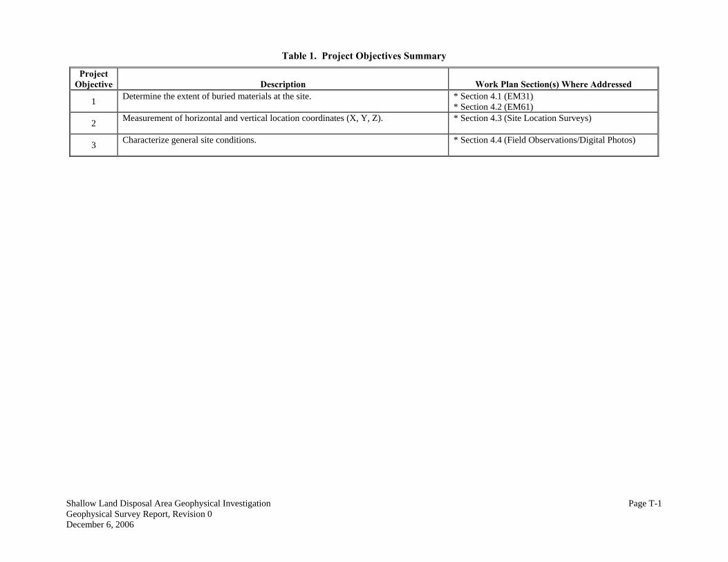
Table 1. Project Objectives Summary
Project Objective
Description
Work Plan Section(s) Where Addressed
Determine the extent of buried materials at the site.
* Section 4.1 (EM31) * Section 4.2 (EM61) 1
Measurement of horizontal and vertical location coordinates (X, Y, Z).
* Section 4.3 (Site Location Surveys) 2
Characterize general site conditions.
* Section 4.4 (Field Observations/Digital Photos) 3
Shallow Land Disposal Area Geophysical Investigation Page T-1 Geophysical Survey Report, Revision 0 December 6, 2006

Table 2. Project Data Needs Summary
Project Objective
Data End-Users
Data Need
Data Quality/Sensitivity
Compliance, Remedy
Non-intrusive geophysical methods to determine the extent of buried material at the site.
* Industry standard sensitivities. * Appropriate for site soil type. * Appropriate for buried material types. * Appropriate for assumed burial depths < 20 ft below ground surface (bgs).
1
Compliance, Remedy
Measurement of horizontal and vertical location coordinates (X, Y, Z). Civil survey data collection for data mapping and reporting.
* Sub-meter accuracy for horizontal locations. 2
Compliance, Remedy
Characterization of general site conditions: - Digital photography to document site conditions and investigation activities. - Field observations regarding site conditions, presence of debris, etc.
* Digital photography to provide better quality and data backup capabilities. * Field observations recorded in field logbooks as required. 3
Shallow Land Disposal Area Geophysical Investigation Page T-2 Geophysical Survey Report, Revision 0 December 6, 2006

allow Land Disposal Area Geophysical Investigation Page T-3 eophysical Survey Report, Revision 0
ber 6, 2006
Table 3. Project Data Collection Options Summary
Data Need
Data Collection Option(s)
Data Quality/Sensitivity
* EM31 Terrain Conductivity * EM61 High Sensitivity Metal Detector
* Survey conducted using 7.5-ft traverse spacing in the trench areas and 15-ft traverse spacing across the remainder of the site. * 70% of signal strength measured to ± 18 ft BGS. * Identify non-native fill material and metallic debris. * Data collection integrated with DGPS data for mapping. * Survey conducted using 5-ft traverse spacing. * Conducted only for EM31 in-phase anomalies. * Define depth to metallic objects to ± 10% depth error. * Higher sensitivity to metallic objects than EM31. * Data collection integrated with DGPS data for mapping.
Non-intrusive geophysical methods to determine the extent of buried material.
* Trimble PRO-XRS DGPS and traditional survey methods
* Sub-meter accuracy for horizontal locations. * Can be integrated with geophysical survey data loggers. * Location surveys of other site features. * Datum: NGVD and the Pennsylvania State Plane South Zone NAD 83 Coordinate System, U.S. Survey Feet.
ShGDecem
Civil survey data collection for data mapping and reporting.
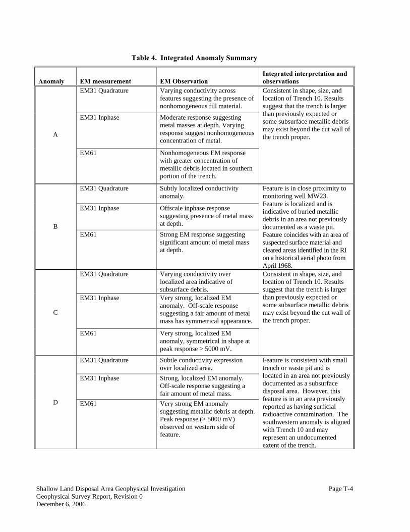
Table 4. Integrated Anomaly Summary
Anomaly EM measurement EM Observation Integrated interpretation and observations
EM31 Quadrature Varying conductivity across features suggesting the presence of nonhomogeneous fill material.
EM31 Inphase Moderate response suggesting metal masses at depth. Varying response suggest nonhomogeneous concentration of metal.
A
EM61 Nonhomogeneous EM response with greater concentration of metallic debris located in southern portion of the trench.
Consistent in shape, size, and location of Trench 10. Results suggest that the trench is larger than previously expected or some subsurface metallic debris may exist beyond the cut wall of the trench proper.
EM31 Quadrature Subtly localized conductivity anomaly.
EM31 Inphase Offscale inphase response suggesting presence of metal mass at depth. B
EM61 Strong EM response suggesting significant amount of metal mass at depth.
Feature is in close proximity to monitoring well MW23. Feature is localized and is indicative of buried metallic debris in an area not previously documented as a waste pit. Feature coincides with an area of suspected surface material and cleared areas identified in the RI on a historical aerial photo from April 1968.
EM31 Quadrature Varying conductivity over localized area indicative of subsurface debris.
EM31 Inphase Very strong, localized EM anomaly. Off-scale response suggesting a fair amount of metal mass has symmetrical appearance.
C
EM61 Very strong, localized EM anomaly, symmetrical in shape at peak response > 5000 mV.
Consistent in shape, size, and location of Trench 10. Results suggest that the trench is larger than previously expected or some subsurface metallic debris may exist beyond the cut wall of the trench proper.
EM31 Quadrature Subtle conductivity expression over localized area.
EM31 Inphase Strong, localized EM anomaly. Off-scale response suggesting a fair amount of metal mass.
D EM61 Very strong EM anomaly suggesting metallic debris at depth. Peak response (> 5000 mV) observed on western side of feature.
Feature is consistent with small trench or waste pit and is located in an area not previously documented as a subsurface disposal area. However, this feature is in an area previously reported as having surficial radioactive contamination. The southwestern anomaly is aligned with Trench 10 and may represent an undocumented extent of the trench.
Shallow Land Disposal Area Geophysical Investigation Page T-4 Geophysical Survey Report, Revision 0 December 6, 2006

Table 4. Integrated Anomaly Summary (continued)
Anomaly EM measurement EM Observation Integrated interpretation and observations
EM31 Quadrature Varying conductivity across features suggesting the presence of nonhomgeneous fill material.
EM31 Inphase Strong response greater than 0.9 ppt suggests metal masses at depth. Varying response suggest nonhomogeneous concentration of metal.
E
EM61 Strong EM response suggestion varying degree of metal masses. Anomaly discontinuities suggest 3 distinct areas of concentrated metals.
Consistent in shape, size, and location of Trench 1. Results suggest that majority of the debris is confined to the limits of the trench proper, however, smaller amounts of subsurface metallic debris is present in adjacent areas.
EM31 Quadrature Elevated conductivity across features suggesting the presence of nonhomogeneous fill material
EM31 Inphase Strong, fairly homogeneous, response suggesting metal masses at depth. Strongest response observed in the northern portion of the trench suggesting greater concentration of subsurface metals at depth.
F
EM61 Strong EM response across this feature suggesting metal masses at depth. Strongest response observed in the southern portion of the trench suggests greater sensitivity to near surface metals.
Consistent in shape, size, and location of Trench 2. Results suggest that majority of the debris is confined to the limits of the trench proper, however, isolated, smaller amounts of subsurface metallic debris is present particularly on the north west side of the suspected trench.
Shallow Land Disposal Area Geophysical Investigation Page T-5 Geophysical Survey Report, Revision 0 December 6, 2006
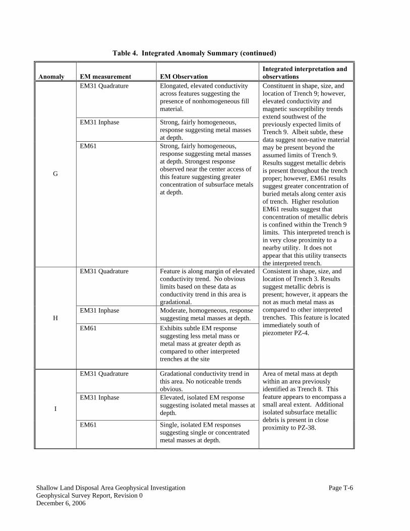
Table 4. Integrated Anomaly Summary (continued)
Anomaly EM measurement EM Observation Integrated interpretation and observations
EM31 Quadrature Elongated, elevated conductivity across features suggesting the presence of nonhomogeneous fill material.
EM31 Inphase Strong, fairly homogeneous, response suggesting metal masses at depth.
G
EM61 Strong, fairly homogeneous, response suggesting metal masses at depth. Strongest response observed near the center access of this feature suggesting greater concentration of subsurface metals at depth.
Constituent in shape, size, and location of Trench 9; however, elevated conductivity and magnetic susceptibility trends extend southwest of the previously expected limits of Trench 9. Albeit subtle, these data suggest non-native material may be present beyond the assumed limits of Trench 9. Results suggest metallic debris is present throughout the trench proper; however, EM61 results suggest greater concentration of buried metals along center axis of trench. Higher resolution EM61 results suggest that concentration of metallic debris is confined within the Trench 9 limits. This interpreted trench is in very close proximity to a nearby utility. It does not appear that this utility transects the interpreted trench.
EM31 Quadrature Feature is along margin of elevated conductivity trend. No obvious limits based on these data as conductivity trend in this area is gradational.
EM31 Inphase Moderate, homogeneous, response suggesting metal masses at depth. H
EM61 Exhibits subtle EM response suggesting less metal mass or metal mass at greater depth as compared to other interpreted trenches at the site
Consistent in shape, size, and location of Trench 3. Results suggest metallic debris is present; however, it appears the not as much metal mass as compared to other interpreted trenches. This feature is located immediately south of piezometer PZ-4.
EM31 Quadrature Gradational conductivity trend in this area. No noticeable trends obvious.
EM31 Inphase Elevated, isolated EM response suggesting isolated metal masses at depth. I
EM61 Single, isolated EM responses suggesting single or concentrated metal masses at depth.
Area of metal mass at depth within an area previously identified as Trench 8. This feature appears to encompass a small areal extent. Additional isolated subsurface metallic debris is present in close proximity to PZ-38.
Shallow Land Disposal Area Geophysical Investigation Page T-6 Geophysical Survey Report, Revision 0 December 6, 2006
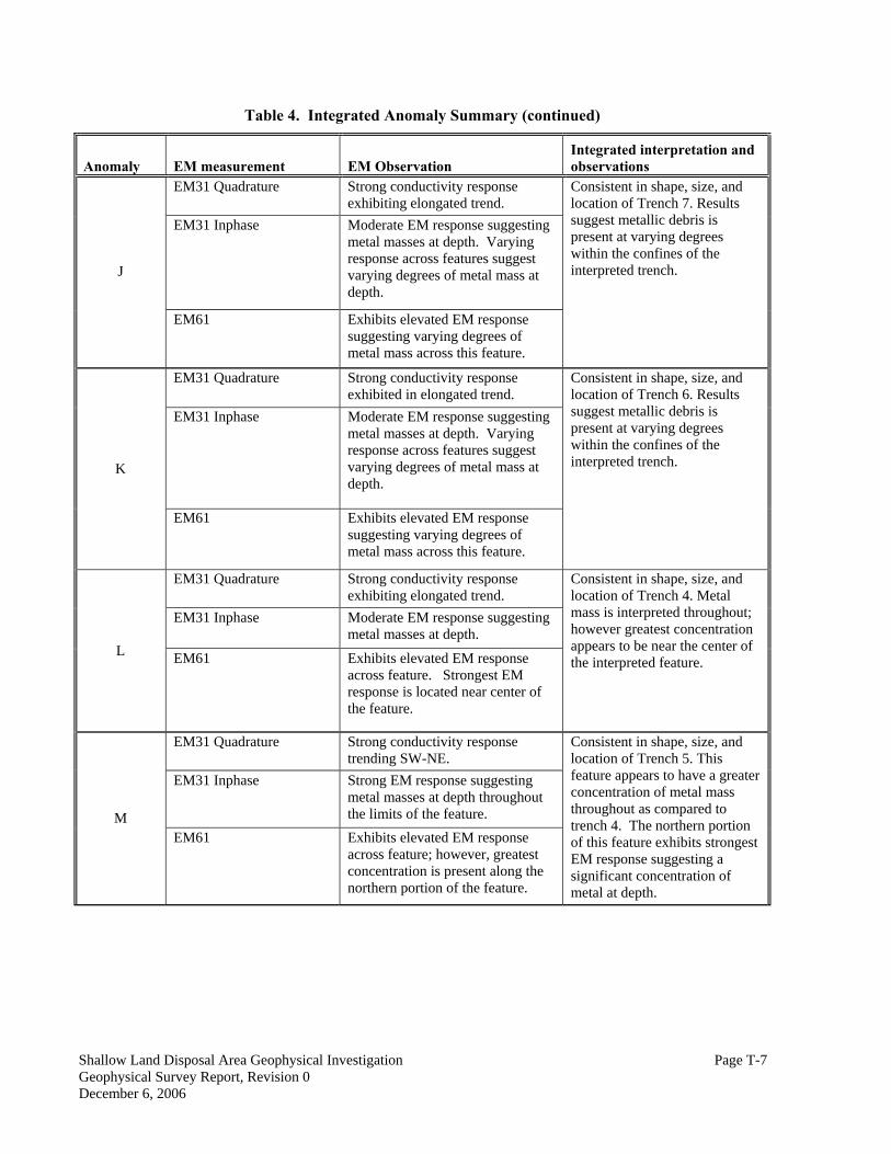
Table 4. Integrated Anomaly Summary (continued)
Anomaly EM measurement EM Observation Integrated interpretation and observations
EM31 Quadrature Strong conductivity response exhibiting elongated trend.
EM31 Inphase Moderate EM response suggesting metal masses at depth. Varying response across features suggest varying degrees of metal mass at depth.
J
EM61 Exhibits elevated EM response suggesting varying degrees of metal mass across this feature.
Consistent in shape, size, and location of Trench 7. Results suggest metallic debris is present at varying degrees within the confines of the interpreted trench.
EM31 Quadrature Strong conductivity response exhibited in elongated trend.
EM31 Inphase Moderate EM response suggesting metal masses at depth. Varying response across features suggest varying degrees of metal mass at depth.
K
EM61 Exhibits elevated EM response suggesting varying degrees of metal mass across this feature.
Consistent in shape, size, and location of Trench 6. Results suggest metallic debris is present at varying degrees within the confines of the interpreted trench.
EM31 Quadrature Strong conductivity response exhibiting elongated trend.
EM31 Inphase Moderate EM response suggesting metal masses at depth.
L EM61 Exhibits elevated EM response across feature. Strongest EM response is located near center of the feature.
Consistent in shape, size, and location of Trench 4. Metal mass is interpreted throughout; however greatest concentration appears to be near the center of the interpreted feature.
EM31 Quadrature Strong conductivity response trending SW-NE.
EM31 Inphase Strong EM response suggesting metal masses at depth throughout the limits of the feature. M
EM61 Exhibits elevated EM response across feature; however, greatest concentration is present along the northern portion of the feature.
Consistent in shape, size, and location of Trench 5. This feature appears to have a greater concentration of metal mass throughout as compared to trench 4. The northern portion of this feature exhibits strongest EM response suggesting a significant concentration of metal at depth.
Shallow Land Disposal Area Geophysical Investigation Page T-7 Geophysical Survey Report, Revision 0 December 6, 2006

Table 4. Integrated Anomaly Summary (continued)
Anomaly EM measurement EM Observation Integrated interpretation and observations
EM31 Quadrature Gradational conductivity trend in this area. No noticeable trends obvious.
EM31 Inphase Gradational conductivity trend in this area. No noticeable trends obvious.
N
EM61 Isolated EM response suggestion localized metallic targets
Localized EM responses coincide to metallic fence posts observed in the field.
EM31 Quadrature Background EM response EM31 Inphase Background EM response
O EM61 EM61 data not collected in this area.
This area is within the fenced off exclusion zone of an area previously demarcated as having surface radiological contamination. No observed features at depth.
EM31 Quadrature Background EM response EM31 Inphase Background EM response
P EM61 EM61 data not collected in this area.
Survey conducted over footprint of mounded soil. Results suggest no debris is present within the EM depth detection limits beneath the emplaced soil piles.
Shallow Land Disposal Area Geophysical Investigation Page T-8 Geophysical Survey Report, Revision 0 December 6, 2006
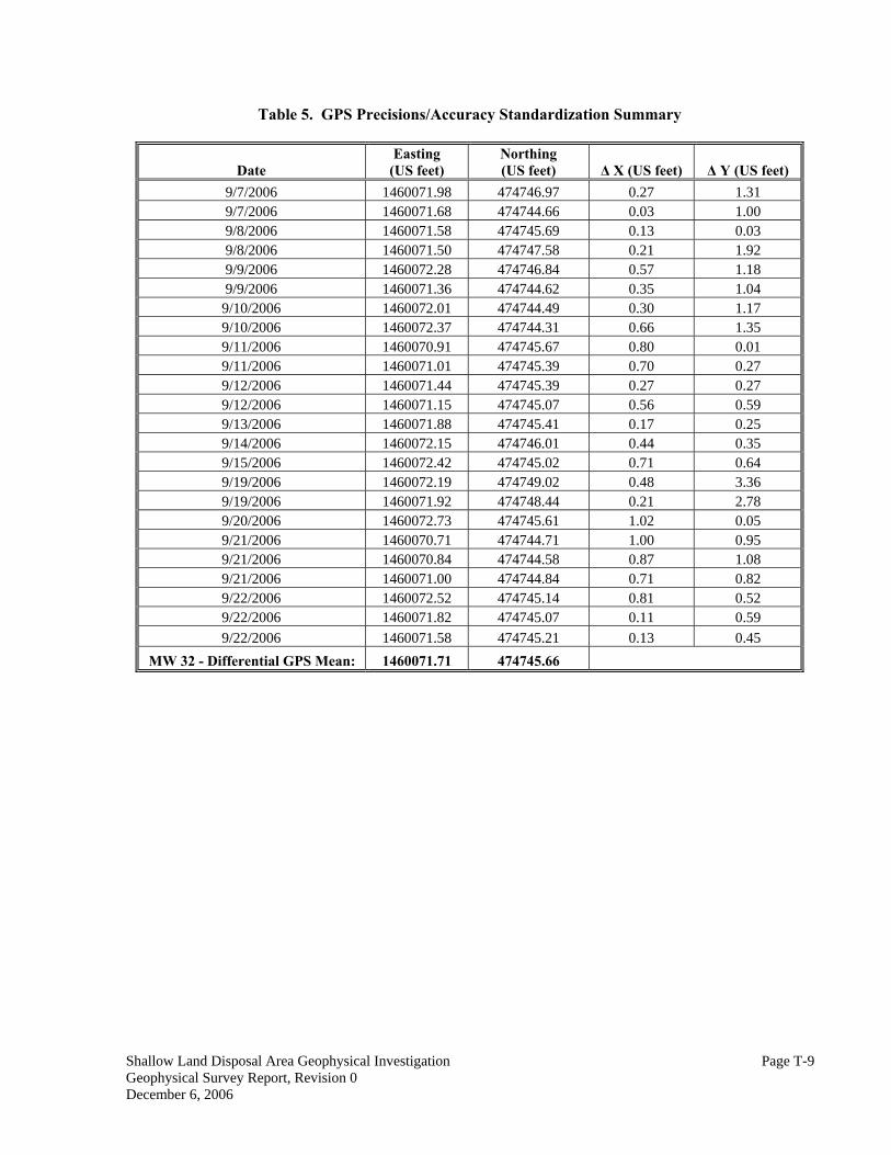
Table 5. GPS Precisions/Accuracy Standardization Summary
Date Easting
(US feet) Northing (US feet) Δ X (US feet) Δ Y (US feet)
9/7/2006 1460071.98 474746.97 0.27 1.31 9/7/2006 1460071.68 474744.66 0.03 1.00 9/8/2006 1460071.58 474745.69 0.13 0.03 9/8/2006 1460071.50 474747.58 0.21 1.92 9/9/2006 1460072.28 474746.84 0.57 1.18 9/9/2006 1460071.36 474744.62 0.35 1.04
9/10/2006 1460072.01 474744.49 0.30 1.17 9/10/2006 1460072.37 474744.31 0.66 1.35 9/11/2006 1460070.91 474745.67 0.80 0.01 9/11/2006 1460071.01 474745.39 0.70 0.27 9/12/2006 1460071.44 474745.39 0.27 0.27 9/12/2006 1460071.15 474745.07 0.56 0.59 9/13/2006 1460071.88 474745.41 0.17 0.25 9/14/2006 1460072.15 474746.01 0.44 0.35 9/15/2006 1460072.42 474745.02 0.71 0.64 9/19/2006 1460072.19 474749.02 0.48 3.36 9/19/2006 1460071.92 474748.44 0.21 2.78 9/20/2006 1460072.73 474745.61 1.02 0.05 9/21/2006 1460070.71 474744.71 1.00 0.95 9/21/2006 1460070.84 474744.58 0.87 1.08 9/21/2006 1460071.00 474744.84 0.71 0.82 9/22/2006 1460072.52 474745.14 0.81 0.52 9/22/2006 1460071.82 474745.07 0.11 0.59 9/22/2006 1460071.58 474745.21 0.13 0.45
MW 32 - Differential GPS Mean: 1460071.71 474745.66
Shallow Land Disposal Area Geophysical Investigation Page T-9 Geophysical Survey Report, Revision 0 December 6, 2006

ShGDecem
allow Land Disposal Area Geophysical Investigation eophysical Survey Report, Revision 0
ber 6, 2006
FIGURES

Shallow Land Disposal Area Geophysical Investigation Geophysical Survey Report, Revision 0 December 6, 2006
APPENDIX A
FIELD PHOTOGRAPHS

Photograph 1. Site View With Trench 1 on Near Left and Trenches 5-8 in Distance
Photograph 2. Reference Grid Pin Flags With Trench 1 on the Right
Shallow Land Disposal Area Geophysical Investigation Page A-1 Geophysical Survey Report, Revision 0 December 6, 2006
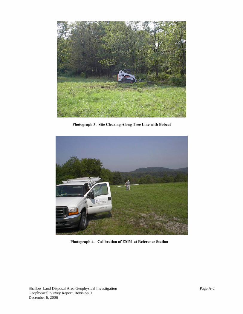
Photograph 3. Site Clearing Along Tree Line with Bobcat
Photograph 4. Calibration of EM31 at Reference Station
Shallow Land Disposal Area Geophysical Investigation Page A-2 Geophysical Survey Report, Revision 0 December 6, 2006
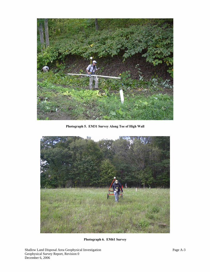
Photograph 5. EM31 Survey Along Toe of High Wall
Photograph 6. EM61 Survey
Shallow Land Disposal Area Geophysical Investigation Page A-3 Geophysical Survey Report, Revision 0 December 6, 2006
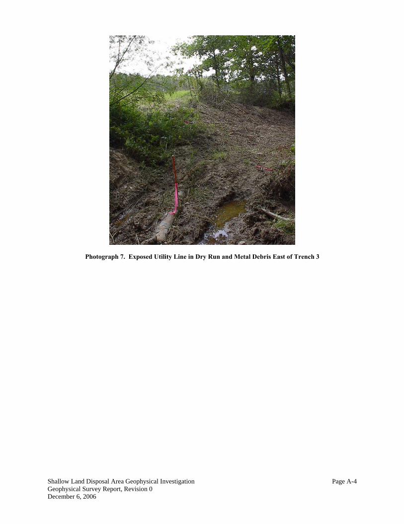
Photograph 7. Exposed Utility Line in Dry Run and Metal Debris East of Trench 3
Shallow Land Disposal Area Geophysical Investigation Page A-4 Geophysical Survey Report, Revision 0 December 6, 2006