geometric design elements
DESCRIPTION
Geometric Design ElementsTRANSCRIPT
5C-2
Design Manual
Chapter 5 - Roadway Design
5C - General Design Criteria
1 Revised: 2013 Edition
Geometric Design Elements
A. Level of Service
Level of service (LOS) is a measure of the operating conditions of a roadway facility. LOS is based
upon traffic performance related to speed, travel time, freedom to maneuver, traffic interruptions, and
comfort and convenience. The LOS ranges from A (least congested) to F (most congested). Refer to
the Highway Capacity Manual for a more thorough discussion of the LOS concept.
Based upon the traffic capacity analysis, the number of lanes, turn lanes, and intersection controls
should be selected to provide a design with the desired LOS for the design year traffic. Design year
traffic is based upon a 20 year traffic projection. The current Highway Capacity Manual and the
current AASHTO “Green Book” should be used for traffic projections and to determine the number
of lanes and intersection configuration at the desired LOS.
The LOS for the roadway overall is based upon Average Daily Traffic (ADT), while the LOS at
signalized intersections is based upon the peak hourly volume (PHV).
As a planning tool, the following tables are provided to indicate approximate capacities for two lane
and four lane streets and highways and intersection capacity for four way stop and signalized
intersections. These tables do not consider site specific details and should not be utilized for final
design purposes.
Table 5C-2.01: Maximum ADT vs. LOS and Type of Terrain for Two Lane Highways
Terrain LOS
B C D
Level 3,200 - 4,800 5,300 - 7,900 9,000 - 13,500
Rolling 1,800 - 2,800 3,500 - 5,200 5,300 - 8,000
Hilly 900 - 1,300 1,600 - 2,400 2,500 - 3,700
Table 5C-2.02: Reduced Capacity of Narrow Lanes with Restricted Lateral Clearance
Usable Shoulder Width or
Clearance to Obstruction (feet)
Two Lane Roadway
(percent of capacity of 12 feet lane)
12 feet lanes 11 feet lanes 10 feet lanes
6 100 93 84
4 92 85 77
2 81 75 68
0 70 65 58

Chapter 5 - Roadway Design Section 5C-2 - Geometric Design Elements
2 Revised: 2013 Edition
Table 5C-2.03: Planning Capacity at LOS C1, D, and E2
Two Way Arterial Streets (Non-intersection)
Number
of Lanes Turn Lanes
Capacity, VPD at LOS D
Minimal
Side Friction
Light
(Residential)
Side Friction
Moderate
(Mixed Zoning)
Side Friction
Heavy
Side Friction
Two Lanes
Undivided
Without turn lanes 12,100 11,600 11,200 10,400
With turn lanes 16,000 15,300 14,000 13,900
Four Lanes
Undivided
Without turn lanes 24,300 23,400 23,400 21,900
With left turn lanes or
5 lane with center TWLTL 32,100 30,900 30,900 29,100
Four Lanes
Divided
Without turn lanes 27,100 26,200 26,100 23,300
With left turn lanes 35,400 34,200 34,100 32,500
With left and right turn lanes 37,500 36,200 34,400 34,400
LOS - Level of Service
TWLTL - Two-Way Left-Turn Lane
VPD - Vehicles per Day 1 Capacity at LOS C may be determined by multiplying LOS D values above by 0.8. 2 Capacity at LOS E may be determined by multiplying LOS D values above by 1.2.
Source: Adapted from “2000 Des Moines Area Daily Directional Capacities At Level of Service D” - Des Moines Area MPO
Table 5C-2.04: Approximate LOS C Service Volumes (VPH) for
Four Way Stop-controlled Intersections (Sum of all Four Legs)
Demand Split Two Lanes on
Each Street
Street 1: Two Lanes
Street 2: Four Lanes
Four Lanes on
Each Street
50/50 1,200 1,800 2,200
55/45 1,140 1,720 2,070
60/40 1,080 1,660 1,970
65/35 1,010 1,630 1,880
70/30 960 1,610 1,820
B. Sight Distance
The following information is taken from the 2004 AASHTO “Green Book.” The Project Engineer
should check the current edition of the AASHTO “Green Book” when specific information is needed
to verify values provided.
1. Stopping Sight Distances: The minimum stopping sight distance is the distance required by the
driver of a vehicle traveling at the design speed to bring the vehicle to a stop after an object on the
road becomes visible. This distance directly affects the length and rate of curvature for vertical
curves.
The method for measuring stopping sight distance on vertical curves assumes a height for the
driver’s eye and a height for an object in the road. For a crest vertical curve, the sight distance is
the distance at which an object in the road appears to the driver over the crest of the curve.

Chapter 5 - Roadway Design Section 5C-2 - Geometric Design Elements
3 Revised: 2013 Edition
Figure 5C-2.01: Vertical Sight Distance Determination
Stopping sight distance is calculated based upon an assumed height of the driver’s eye and an
assumed height of an object in the roadway. For all sight distance criteria, the height of the
driver’s eye is assumed to be 3.5 feet above the surface of the road, as recommended by
AASHTO. Tables 5C-1.01 and 5C-1.02 in Section 5C-1 assume two different values for the
height of the object in the roadway. The “Acceptable” values in Table 5C-1.02 use a 2 foot
object height according to the current edition of the AASHTO “Green Book.” The “Preferred”
values in Table 5C-1.01 assume an object height of only 6 inches. This lower object height was
the design value used in previous versions of the AASHTO “Green Book.” The results of
assuming a smaller object height for the preferred values in Table 5C-1.01 are higher required K
values and longer vertical curves.
2. Sight Distance on Horizontal Curves: The horizontal alignment must provide at least the
minimum stopping distance for the design speed at all points. This includes visibility around
curves and roadside encroachments.
Where there are sight obstructions such as walls, cut slopes, buildings, fences, bridge structures,
or other longitudinal barriers on the inside of curves, an adjustment in the minimum radius of the
curve may be necessary. In no case should sight distance be less than the stopping sight distance
specified in Tables 5C-1.01 and 5C-1.02 in Section 5C-1. The sight distance design procedure
should assume a 6 foot fence (as measured from finished grade) exists along all property lines
except in the sight distance triangles required at all intersections.
Available sight distance around a horizontal curve can be determined graphically using the
method shown in Figures 5C-2.02 and 5C-2.03 below. From the center of the inside lane (Point
A), a line is projected through the point on the obstruction that is nearest to the curve (Point B).
The line is then extended until it intersects the centerline of the inside lane (Point C).

Chapter 5 - Roadway Design Section 5C-2 - Geometric Design Elements
4 Revised: 2013 Edition
Figure 5C-2.02 and Figure 5C-2.03: Sight Distances for Horizontal Curves
Source: Adapted from AASHTO “Green Book,” 2004 Edition, Exhibits 3-53 and 3-54

Chapter 5 - Roadway Design Section 5C-2 - Geometric Design Elements
5 Revised: 2013 Edition
3. Passing Sight Distance: Passing sight distance is the minimum sight distance that must be
available to enable the driver of one vehicle to pass another safely and comfortably without
interfering with oncoming traffic traveling at the design speed. Two lane roads should provide
adequate passing zones at regular intervals. Minimum passing sight distances are shown in
Tables 5C-1.01 and 5C-1.02 in Section 5C-1.
Passing sight distance is measured between an eye height of 3.5 feet and an object height of 3.5
feet. On straight sections of roadway, passing sight distance is determined primarily by the
vertical curvature of the roadway. On horizontal curves, obstructions adjacent to the roadway on
the inside of the curve can limit sight distance. This is most common in a cut section where the
adjacent terrain projects above the surface of the roadway. Passing sight distance should be
verified using the methods described in the current edition of the AASHTO “Green Book.”
4. Intersection Sight Distance: In addition to the stopping sight distance provided continuously in
the direction of travel on all roadways, adequate sight distance at intersections must be provided
to allow drivers to perceive the presence of potentially conflicting vehicles. Sight distance is also
required at intersections to allow drivers of stopped vehicles to decide when to enter or cross the
intersecting roadway. If the available sight distance for an entering or crossing vehicle is at least
equal to the appropriate stopping sight distance for the major road, then drivers have sufficient
sight distance to anticipate and avoid collisions. However, in some cases, this may require a
major road vehicle to slow or stop to accommodate the maneuver by a minor road vehicle. To
enhance traffic operations, intersection sight distances that exceed stopping sight distances are
desirable along the major road.
Each intersection has the potential for several different types of vehicular conflicts. The
possibility of these conflicts actually occurring can be greatly reduced by providing proper sight
distance and appropriate traffic controls. Each quadrant of an intersection should contain a
triangular area free of obstructions that might block an approaching driver’s view of potentially
conflicting vehicles. This clear area is known as the sight triangle.
a. Sight Triangles: Proper sight distance at intersections is determined through the
establishment and enforcement of sight triangles. The required dimensions of the legs of the
triangle depend on the design speed of the roadways and the type of traffic control provided
at the intersection. Two types of clear sight triangles are considered in intersection design:
approach sight triangles and departure sight triangles.
1) Approach Sight Triangles: Approach sight triangles allow the drivers at uncontrolled
or yield controlled intersections to see a potentially conflicting vehicle in sufficient time
to slow or stop before colliding within the intersection. Although desirable at all
intersections, approach sight triangles are not needed for intersections approaches
controlled by stop signs or traffic signals.
2) Departure Sight Triangles: A second type of clear sight triangle provides sight distance
sufficient for a stopped driver on a minor-road approach to depart from the intersection
and enter or cross the major road. Departure sight triangles should be provided in each
quadrant of each intersection approach controlled by a stop sign.
At signalized intersections, the first vehicle stopped on one approach should be visible to the
driver of the first vehicle stopped on each of the other approaches. Left turning vehicles
should have sufficient sight distance to select gaps in oncoming traffic.
The recommended dimensions of the sight triangles vary with the type of traffic control used
at an intersection because different types of controls impose different legal constraints on
drivers and, therefore, result in different driver behavior. The AASHTO “Green Book”
Chapter 5 - Roadway Design Section 5C-2 - Geometric Design Elements
6 Revised: 2013 Edition
contains the required procedures, equations, and tables for determining the required sight
distance under various intersection and traffic control configurations.
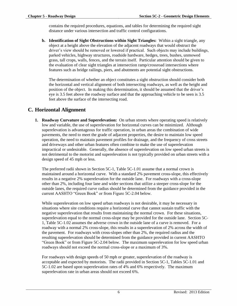
b. Identification of Sight Obstructions within Sight Triangles: Within a sight triangle, any
object at a height above the elevation of the adjacent roadways that would obstruct the
driver’s view should be removed or lowered if practical. Such objects may include buildings,
parked vehicles, highway structures, roadside hardware, hedges, trees, bushes, unmowed
grass, tall crops, walls, fences, and the terrain itself. Particular attention should be given to
the evaluation of clear sight triangles at intersection ramp/crossroad intersections where
features such as bridge railings, piers, and abutments are potential sight obstructions.
The determination of whether an object constitutes a sight obstruction should consider both
the horizontal and vertical alignment of both intersecting roadways, as well as the height and
position of the object. In making this determination, it should be assumed that the driver’s
eye is 3.5 feet above the roadway surface and that the approaching vehicle to be seen is 3.5
feet above the surface of the intersecting road.
C. Horizontal Alignment
1. Roadway Curvature and Superelevation: On urban streets where operating speed is relatively
low and variable, the use of superelevation for horizontal curves can be minimized. Although
superelevation is advantageous for traffic operation, in urban areas the combination of wide
pavements, the need to meet the grade of adjacent properties, the desire to maintain low speed
operation, the need to maintain pavement profiles for drainage, and the frequency of cross streets
and driveways and other urban features often combine to make the use of superelevation
impractical or undesirable. Generally, the absence of superelevation on low speed urban streets is
not detrimental to the motorist and superelevation is not typically provided on urban streets with a
design speed of 45 mph or less.
The preferred radii shown in Section 5C-1, Table 5C-1.01 assume that a normal crown is
maintained around a horizontal curve. With a standard 2% pavement cross-slope, this effectively
results in a negative 2% superelevation for the outside lane. For roadways with a cross-slope
other than 2%, including four lane and wider sections that utilize a steeper cross-slope for the
outside lanes, the required curve radius should be determined from the guidance provided in the
current AASHTO “Green Book” or from Figure 5C-2.04 below.
While superelevation on low speed urban roadways is not desirable, it may be necessary in
situations where site conditions require a horizontal curve that cannot sustain traffic with the
negative superelevation that results from maintaining the normal crown. For these situations,
superelevation equal to the normal cross-slope may be provided for the outside lane. Section 5C-
1, Table 5C-1.02 assumes the adverse crown in the outside lane of a curve is removed. For a
roadway with a normal 2% cross-slope, this results in a superelevation of 2% across the width of
the pavement. For roadways with cross-slopes other than 2%, the required radius and the
resulting superelevation should be determined from the guidance provided in current AASHTO
“Green Book” or from Figure 5C-2.04 below. The maximum superelevation for low speed urban
roadways should not exceed the normal cross-slope or a maximum of 3%.
For roadways with design speeds of 50 mph or greater, superelevation of the roadway is
acceptable and expected by motorists. The radii provided in Section 5C-1, Tables 5C-1.01 and
5C-1.02 are based upon superelevation rates of 4% and 6% respectively. The maximum
superelevation rate in urban areas should not exceed 6%.

Chapter 5 - Roadway Design Section 5C-2 - Geometric Design Elements
7 Revised: 2013 Edition
Figure 5C-2.04: Superelevation, Radius, and Design Speed for Low Speed (<50mph)
Urban Street Design
Source: AASHTO “Green Book,” 2004 Edition, Exhibit 3-17
2. Intersection Alignment: The centerline of a street approaching another street from the opposite
side should not be offset. If the offset cannot be avoided, the offset should be 150 feet or greater
for local streets. The centerline of a local street approaching an arterial or collector street from
opposite side should not be offset unless such offset is 300 feet or greater.
3. Adding, Dropping, or Redirecting Lanes:
a. Dropping or Redirecting Through Lanes: When dropping a lane, the minimum taper ratio
to be used should be determined by the following formula, or from Table 5C-2.05:
L = WS for velocities of 45 mph or more
L = WS2 for velocities of 40 mph or less.
60
L = Minimum length of taper.
S = Numerical value of posted speed limit or 85th percentile speed, whichever is higher.
W = Width of pavement to be dropped or redirection offset.
Preferably, taper ratios should be evenly divisible by five. Calculations that result in odd
ratios should be rounded to an even increment of five. The table below utilizes the formulas
to determine the appropriate taper ratio for dropping a 12 foot wide lane. The ratio remains
constant for a given design speed while the length varies with the pavement width.

Chapter 5 - Roadway Design Section 5C-2 - Geometric Design Elements
8 Revised: 2013 Edition
The procedure for determining minimum taper ratios for redirecting through lanes is the same
as for lane drops, except for design speeds over 45 mph the use of reverse curves rather than
tapers is recommended.
Table 5C-2.05: Length and Taper Ratio for Dropping 12 Foot Lane
Design Speed (mph) 25 30 35 40 45 50 55 60
Taper Ratio 10:1 15:1 20:1 25:1 45:1 50:1 55:1 60:1
Length (feet) 120 180 240 300 540 600 660 720
b. Adding Through or Turn Lanes: For design speeds of 45 mph or greater, a 15:1 lane taper
should be used when adding a left or right turn lane. For design speeds less than 45 mph, a
10:1 taper may be used.
For design speeds less than 45 mph, shorter tapers that are squared off or taper at 1:1 may
provide better “targets” for approaching drivers and give more positive identification to an
added through lane or turn lane. For turn lanes, the total length of taper and deceleration
length should be the same as if a standard taper was used. This results in a longer length of
full width pavement for the turn lane. This design provides increased storage that may reduce
the likelihood turning vehicles will back up into the through lane during peak traffic periods.
The use of short taper sections must be approved by the Engineer.
Figure 5C-2.05: Adding or Dropping Lanes
Figure 5C-2.06: Redirecting Through Lanes

Chapter 5 - Roadway Design Section 5C-2 - Geometric Design Elements
9 Revised: 2013 Edition
D. Vertical Alignment
1. Minimum Grades: Flat and level grades on uncurbed pavements are preferred when the
pavement is adequately crowned to drain the surface laterally. However, with curbed pavements,
longitudinal grades must be provided to facilitate surface drainage. A typical minimum grade is
0.5%, but a grade of 0.4% may be used in isolated areas where the pavement is accurately
crowned and supported on firm subgrade. The minimum allowance grade for bubbles and cul-de-
sacs is 1%. Particular attention should be given to the design of stormwater inlets and their
spacing to keep the spread of water on the traveled way within tolerable limits. Roadside
channels and median swales frequently require grades steeper than the roadway profile for
adequate drainage.
2. Maximum Grades: Grades for urban streets should be as level as practical, consistent with the
surrounding terrain. The maximum design grades specified in Section 5C-1, Table 5C-1.02
should be used infrequently; in most cases grades should be less than the maximum design grade.
Where sidewalks are located adjacent to a roadway, a maximum roadway grade of 5% is
desirable. ADA requirements allow sidewalks adjacent to a roadway to match the running grade
of the roadway, regardless of the resulting grade. However, sidewalk accessibility is greatly
enhanced, especially over long distances, when grades are limited to 5% or less. It is recognized
that meeting limitations will not be possible or practical in many situations; however, an attempt
should be made to limit roadway grades to this level, especially in areas with high levels of
anticipated pedestrian usage.
3. Maximum Grade Changes: Except at intersections, the use of grade breaks, in lieu of vertical
curves, is not encouraged. However, if a grade break is necessary and the algebraic difference in
grade does not exceed 1%, the grade break will be considered by the Engineer.
4. Vertical Curves: Vertical curves should be simple in application and should result in a design
that is safe, comfortable in operation, pleasing in appearance, and adequate for drainage.
The major control for safe operation on crest vertical curves is the provision of ample sight
distances for the design speed. Minimum stopping sight distance should be provided in all cases.
Wherever economically and physically feasible, more liberal stopping sight distances should be
used. Furthermore additional sight distance should be provided at decision points.
a. Crest Vertical Curves: Minimum lengths of crest vertical curves as determined by sight
distance requirements are generally satisfactory from the standpoint of safety, comfort, and
appearance. Figure 5C-2.06 shows the required length of crest vertical curve to provide
stopping sight distance based upon design speed and change in grade.
b. Sag Vertical Curves: Headlight sight distance is generally used as the criteria for
determining the length of sag vertical curves. When a vehicle approaches a sag vertical curve
at night, the portion of highway lighted ahead is dependent on the position of the headlights
and the direction of the light beam. A headlight height of 2 feet and a 1 degree upward
divergence of the light beam from the longitudinal axis of the vehicle is commonly assumed.
For safety purposes, the sag vertical curve should be long enough that the light beam distance
is the same as the stopping sight distance. Figure 5C-2.07 specifies the required sag curve
length to meet the sight distance assumptions made above.

Chapter 5 - Roadway Design Section 5C-2 - Geometric Design Elements
10 Revised: 2015 Edition
For both sag and crest vertical curves with a low algebraic difference in grade, sight distance
restrictions may not control the design of the curve. In these cases, rider comfort and curve
appearance are the primary considerations for vertical curve design. Generally, vertical curves
with a minimum length (in feet) equal to three times the design speed (in mph) are acceptable.
If a roadway has continuous lighting, the length of sag vertical curve (L) may be based on
passenger comfort instead of headlight sight distance. Use the following equation for the curve
length:
𝐿 = 𝐴𝑉2
46.5
where A = algebraic difference in grades, %
V = design speed, mph
(Equation 3-51 AASHTO Greenbook, 2011)
Drainage considerations also affect the design of vertical curves where curbs are utilized. Both
crest and sag vertical curves that have a grade change from positive to negative (or vice versa)
contain a level area at some point along the curve. Generally, as long as a grade of 0.30% is
provided within 50 feet of the level area, no drainage problems develop. This criterion
corresponds to a K value of 167 and is indicated by a dashed line in Figures 5C-2.06 and 5C-2.07
below. K values greater than 167 may be utilized, but additional consideration should be given to
drainage in these situations.
12 gg
ftL
K where g1 and g2 are in percent
Figure 5C-2.06: Design Controls for Crest Vertical Curves
for Stopping Sight Distance and Open Road Conditions
Source: “Green Book,” Exhibit 3-71, 2004

Chapter 5 - Roadway Design Section 5C-2 - Geometric Design Elements
11 Revised: 2013 Edition
Figure 5C-2.07: Design Controls for Sag Vertical Curves, Open Road Conditions
Source: “Green Book,” Exhibit 3-78, 2004
5. Intersection Grades: The grade of the "through" street should take precedence at intersections.
At intersections of roadways with the same classifications, the more important roadway should
have this precedence. Side streets are to be warped to match through streets with as short a
transition as possible, which provides a smooth ride. Consideration must be given to minimize
sheet flow of stormwater across the intersection due to loss of crown on the side street.
Carrying the crown of the side street into the through street is not allowed. In most cases the
pavement cross-slope at the warped intersection should not exceed the grade of the through street.
The maximum desirable grades of the through street at the intersection and the side street cross-
slope should be 2% and should not exceed 3%. The maximum desirable approach grade of the
side street should not exceed 4% for a distance of 100 feet from the curb of the through street.
Establishing intersection spot grades by matching “curb corners” of intersecting streets is not
recommended since it may result in an undesirable travel path from the through street to the side
street because of the resulting bump on the side street centerline. At sidewalk curb ramps in
intersections, the street grades may need to be warped at the curb line to ensure the resulting
cross-slope at the bottom of the ramp does not exceed 2%. A detail of the jointing layout with
staking elevations should be shown on the plans.
ADA regulations set specific limits for crosswalk cross-slopes that directly impact street and
intersection grades. ADA regulations limit the cross-slope to 2% (measured perpendicular to the
direction of pedestrian travel) for crosswalks that cross a roadway with stop control (stop sign) at
the intersection. For roadways without stop control (through movement or traffic signal) the
cross-slope of the crosswalk is limited to 5%. Effectively, this requirement limits street grades to
a maximum of 2% or 5% depending on intersection controls.
For steep roadways without stop control, construction of a flattened “table” may be necessary to
reduce the street grade to 5% or less at the location of the crosswalk. Crosswalk tables at these

Chapter 5 - Roadway Design Section 5C-2 - Geometric Design Elements
12 Revised: 2013 Edition
locations must utilize vertical curves, appropriate for the design speed, to avoid a sudden change
in grade at the intersection that could cause vehicles to bottom out or lose control.
For steep roadways with stop control, construction of a flattened “table” may utilize grade breaks
or shortened vertical curves to reduce the street grade to 2% or less at the location of the
crosswalk. A check should be made to verify that vehicles will not bottom out when traveling
over the crosswalk table.
E. Pavement Crowns
The following typical pavement crowns are straight line cross-slope and are desirable sections.
1. Urban Roadways (Curb and Gutter): For streets with three or fewer travel lanes, the pavement
crown should be 2%.
For streets with four or more travel lanes, the pavement crown for all inside lanes, including left
turn lanes, should be 2%. In order to reduce stormwater spread, the pavement crown for the
outside lanes should be 3%.
For all streets, auxiliary right turn lanes will have varying pavement crowns depending on the
desired drainage pathway.
2. Rural Roadways: For pavement crowns, a 2% cross-slope is normal with 4% shoulder slope.
Iowa DOT Standard Road Plans should be checked for Federal Aid, Farm to Market, and
Secondary Roads.
F. Lane Width
The lane width of a roadway greatly influences the safety and comfort of driving. Narrow lanes force
drivers to operate their vehicles closer to each other laterally than they would normally desire,
resulting in driver discomfort, lower operating speeds, and reduced roadway capacity.
Tables 5C-1.01 and 5C-1.02 in Section 5C-1 indicate minimum lane widths based upon the roadway
classification and adjacent land use. In addition to the lane width, a separate offset distance to the
curb is required. This curb offset is not included in the lane widths listed.
Auxiliary lanes and turn lanes at intersections should be as wide as the adjacent through lanes. The
width for turn lanes is measured to the face of curb. Because motorists are slowing in anticipation of
making a turning movement, drivers are comfortable operating their vehicle closer to an adjacent
obstacle (curb); therefore, turn lanes do not require a curb offset.
G. Two-way Left-turn Lanes (TWLTL)
Two-way left-turn lanes work well where design speeds are relatively low (25 to 50 mph) and there
are no heavy concentrations of left turning traffic. The width of TWLTLs should be limited to a
maximum of 14 feet to discourage left-turning motorists from pulling out into the TWLTL and
stopping perpendicular to the direction of traffic, while they wait for oncoming traffic to clear.
Chapter 5 - Roadway Design Section 5C-2 - Geometric Design Elements
13 Revised: 2013 Edition
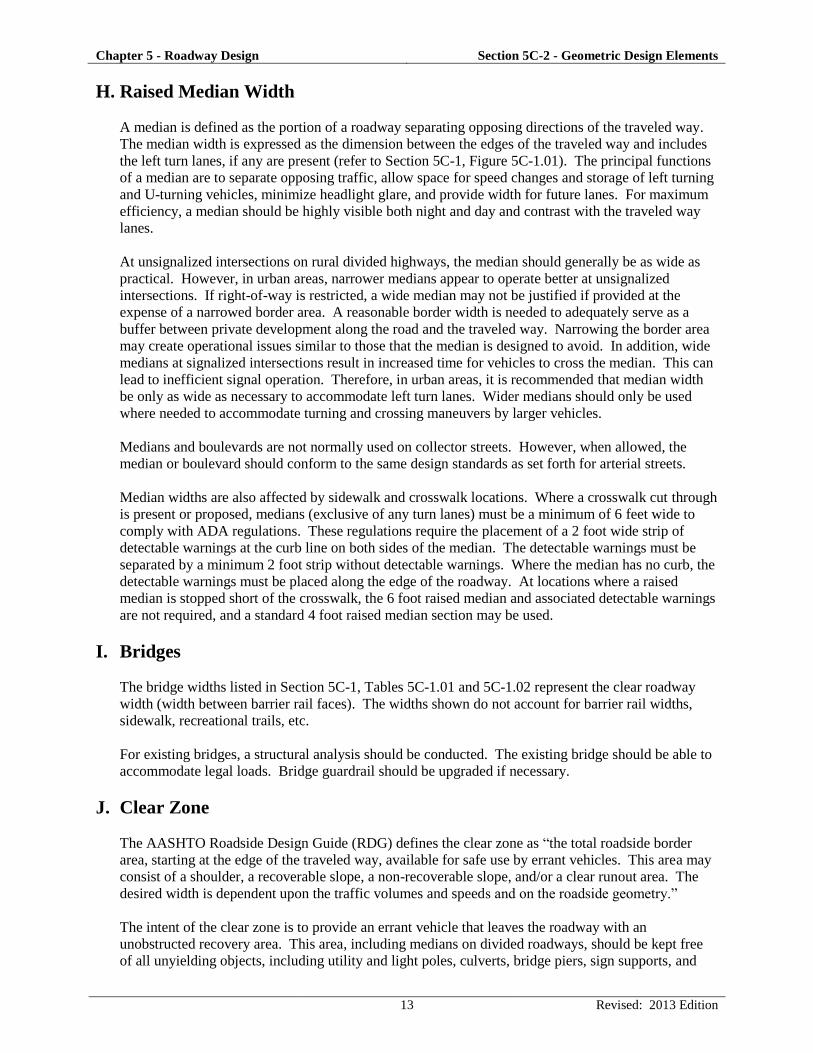
H. Raised Median Width
A median is defined as the portion of a roadway separating opposing directions of the traveled way.
The median width is expressed as the dimension between the edges of the traveled way and includes
the left turn lanes, if any are present (refer to Section 5C-1, Figure 5C-1.01). The principal functions
of a median are to separate opposing traffic, allow space for speed changes and storage of left turning
and U-turning vehicles, minimize headlight glare, and provide width for future lanes. For maximum
efficiency, a median should be highly visible both night and day and contrast with the traveled way
lanes.
At unsignalized intersections on rural divided highways, the median should generally be as wide as
practical. However, in urban areas, narrower medians appear to operate better at unsignalized
intersections. If right-of-way is restricted, a wide median may not be justified if provided at the
expense of a narrowed border area. A reasonable border width is needed to adequately serve as a
buffer between private development along the road and the traveled way. Narrowing the border area
may create operational issues similar to those that the median is designed to avoid. In addition, wide
medians at signalized intersections result in increased time for vehicles to cross the median. This can
lead to inefficient signal operation. Therefore, in urban areas, it is recommended that median width
be only as wide as necessary to accommodate left turn lanes. Wider medians should only be used
where needed to accommodate turning and crossing maneuvers by larger vehicles.
Medians and boulevards are not normally used on collector streets. However, when allowed, the
median or boulevard should conform to the same design standards as set forth for arterial streets.
Median widths are also affected by sidewalk and crosswalk locations. Where a crosswalk cut through
is present or proposed, medians (exclusive of any turn lanes) must be a minimum of 6 feet wide to
comply with ADA regulations. These regulations require the placement of a 2 foot wide strip of
detectable warnings at the curb line on both sides of the median. The detectable warnings must be
separated by a minimum 2 foot strip without detectable warnings. Where the median has no curb, the
detectable warnings must be placed along the edge of the roadway. At locations where a raised
median is stopped short of the crosswalk, the 6 foot raised median and associated detectable warnings
are not required, and a standard 4 foot raised median section may be used.
I. Bridges
The bridge widths listed in Section 5C-1, Tables 5C-1.01 and 5C-1.02 represent the clear roadway
width (width between barrier rail faces). The widths shown do not account for barrier rail widths,
sidewalk, recreational trails, etc.
For existing bridges, a structural analysis should be conducted. The existing bridge should be able to
accommodate legal loads. Bridge guardrail should be upgraded if necessary.
J. Clear Zone
The AASHTO Roadside Design Guide (RDG) defines the clear zone as “the total roadside border
area, starting at the edge of the traveled way, available for safe use by errant vehicles. This area may
consist of a shoulder, a recoverable slope, a non-recoverable slope, and/or a clear runout area. The
desired width is dependent upon the traffic volumes and speeds and on the roadside geometry.”
The intent of the clear zone is to provide an errant vehicle that leaves the roadway with an
unobstructed recovery area. This area, including medians on divided roadways, should be kept free
of all unyielding objects, including utility and light poles, culverts, bridge piers, sign supports, and

Chapter 5 - Roadway Design Section 5C-2 - Geometric Design Elements
14 Revised: 2013 Edition
any other fixed objects that might severely damage an out of control vehicle. Any obstruction that
cannot be placed outside of the clear zone should be shielded by traffic barriers or guardrails.
According to the AASHTO RDG, the width of this area varies based upon traffic volumes, design
speed, and embankment slope.
Embankment slopes can be classified as recoverable, non-recoverable, or critical. Embankment
slopes of 4:1 and flatter are considered recoverable. Drivers who encroach on recoverable slopes can
generally stop their vehicles or slow them enough to return to the roadway safely.
A non-recoverable slope is defined as one that is passable, but from which most motorists will be
unable to stop or to return to the roadway easily. Vehicles on such slopes are likely to reach the
bottom before stopping. Embankments between 3:1 and 4:1 generally fall into this category. Since
many vehicles will reach the toe of these slopes, the clear zone distance cannot logically end on a
non-recoverable slope, and a clear runout area at the base of the slope is required. Fixed objects
should not be present on a non-recoverable slope.
A critical slope is one on which a vehicle is likely to overturn. Slopes steeper than 3:1 generally fall
into this category. If a slope steeper than 3:1 begins closer to the traveled way than the suggested
clear zone, a barrier might be warranted if the slope cannot be flattened.
Figure 5C-2.08: Clear Zone Components
Source: Adapted from Roadside Design Guide, 2006
For horizontal curves, an adjustment factor may be applied to the clear zone width taken from Section
5C-1, Tables 5C-1.03 or 5C-1.04. This adjustment is only required at selected locations. Widening
the clear zone should be considered along the outside of curves when crash history suggests the need
for additional clear zone width, or whenever the radius of the curve is less than 2,860 feet, the design
speed is 55 mph or greater, and the curve occurs on a normally tangent alignment (one where the
curve is preceded by a tangent more than a mile in length).
The clear zone along an urban section may contain minor obstructions (traffic signs, mailboxes, etc.).
In addition, along lower (<40 mph design speed) urban roadways, larger objects designed to "break-
away" when struck by a vehicle may also be located within the clear zone (light poles, cast-iron fire
hydrants, etc.). All objects, however, should be kept free from the object setback zone as described in
the next section.

Chapter 5 - Roadway Design Section 5C-2 - Geometric Design Elements
15 Revised: 2013 Edition
K. Object Setback
Like clear zone, object setback is intended to provide an area adjacent to the roadway that is clear of
obstructions. However, the purpose of the object setback is to provide an operational clearance to
increase driver comfort and avoid a negative impact on traffic flow. It also improves aesthetics,
provides an area for snow storage and, in areas with curbside parking, provides a clear area to open
car doors.
As discussed in the previous section on clear zone, minor obstructions and larger "breakaway" objects
may be located in the clear zone on lower speed roadways (<40 mph design speed), but must be kept
free from the object setback. Mailboxes constructed and installed according to US Postal Service
regulations, including breakaway supports, may be located within the object setback area.
Additional object setback, as measured from the back of curb, may be required around radii at
intersections and driveways in order to provide sufficient clearance to keep the overhang of a truck
from striking an object.
L. Border Area
Border area is the area between the roadway and the right-of-way line and is sometimes referred to as
the "parking" in urban areas. The grade for the border area is normally 1/2 inch per foot. The border
area between the roadway and the right of way line should be wide enough to serve several purposes
including provision of a buffer space between pedestrians and vehicular traffic, sidewalk space, and
an area for both underground and above ground utilities such as storm sewer, traffic signals, parking
meters, and fire hydrants. The border area also provides snow storage and aesthetic features such as
grass or other landscaping features. The border width ranges from 14 to 16 feet, including the
sidewalk width. Traffic signals, utility poles, fire hydrants, and other utilities should be placed as far
back of the curb as practical for safety reasons. Breakaway features should be built when feasible and
as an aid to safety considerations.
Table 5C-2.08: Preferred Border Area
Street Classification Border Area Width (feet)
Major/minor arterial 16
Collector 14.5
Local streets 14
M. Curbs
1. Curb Offset: The curb offset is measured from the back of curb to the edge of the lane. The
curb offset increases driver comfort and roadway safety. The presence of the curb, and potential
vehicle damage and loss of control resulting from striking the curb, causes drivers to move away
from the curb, reducing the effective width of the through lane. Due to this driver reaction, and to
accommodate the flow of drainage and intake structures, an offset between the curb and the edge
of the traveled way is provided.
The curb offset widths specified in Section 5C-1, Tables 5C-1.01 and 5C-1.02 do not necessarily
indicate the width of the curb and gutter or the location of a longitudinal joint; however, the width
of the curb and gutter can affect the required width of the curb offset. The presence of a
longitudinal joint near the curb (gutterline jointing) can be a limiting factor for usable lane width
as some drivers are uncomfortable driving on or near the joint line. This is especially true for
HMA roadways with PCC curb and gutter. For pavements with a longitudinal joint line near the

Chapter 5 - Roadway Design Section 5C-2 - Geometric Design Elements
16 Revised: 2013 Edition
gutter, the curb offset should be equal to or greater than the width of the curb and gutter section.
In addition, grates and special shaping for curb intakes and depressions for open-throat intakes
should be located within the curb offset width and should not encroach into the lane.
2. Curb and Gutter: Typically, a curb and gutter cross-section should consists of a 6 inch high, 6
inch wide curb with a concrete gutter section. If the design speed is 40 mph or below, an 8 inch
curb may be used for certain arterial and collector streets. For design speeds greater than 40 mph,
a 1 foot wide, 6 inch high sloped curb with a minimum 2 foot gutter offset should be used.
N. Parking Lane
Where curbed sections are used, the curb offset width may be included as part of the parking lane.
1. Parking lanes are not allowed on arterial streets.
2. Although on-street parking may impede traffic flow, parallel parking may be allowed by the
Jurisdiction on urban collectors where sufficient street width is available to provide parking lanes.
3. Parking lane width determinations should include consideration for the potential use of the lane as
a through or turn lane for moving traffic either during peak hours or continuously. If this
potential exists, additional parking width should be provided.
O. Cul-de-sacs
A local street open at one end only should have a cul-de-sac constructed at the closed-end. The
minimum radius for cul-de-sacs is 45 feet, which may be increased in commercial areas or if
significant truck traffic is anticipated. The border area around the cul-de-sac should be the same as
the approach street. The transition radius with the approach street will be 50 feet for residential
streets and 75 feet for commercial and industrial streets.
P. Shoulder Width
Shoulders accommodate stopped vehicles, emergency use, and provide lateral support of the subbase
and pavement. In some cases, the shoulder can accommodate bicyclists. Where no curb and gutter is
constructed a soil, granular, or paved shoulder will be provided.
Desirably, a vehicle stopped on the shoulder should clear the pavement edge by 2 feet. This
preference has led to the adoption of 10 feet as the desirable shoulder width that should be provided
along high volume facilities. In difficult terrain and on low volume highways, usable shoulders of
this width may not be practical.
Where roadside barriers, walls, or other vertical elements are used, the graded shoulder should be
wide enough that these vertical elements can be offset a minimum of 2 feet from the outer edge of the
usable shoulder. It may be necessary to provide a graded shoulder wider than used elsewhere on the
curved section of a roadway or to provide lateral support for guardrail posts and/or clear space for
lateral dynamic deflection required by the particular barrier in use. On low volume roads, roadside
barriers may be placed at the outer edge of the shoulder; however, a minimum of 4 feet should be
provided from the traveled way to the barrier.

Chapter 5 - Roadway Design Section 5C-2 - Geometric Design Elements
17 Revised: 2013 Edition
Q. Intersection Radii
Minimum curb return radii are shown in Table 5C-2.09 below. Where truck traffic is significant, curb
return radii should be provided according to the current AASHTO “Green Book;” turning templates
are used in this design. The Iowa DOT has an Iowa truck vehicle that can be used to check the
proposed radii for truck routes.
Table 5C-2.09: Curb Return Radii Based Upon Roadway Classification
Roadway Classification Arterial Collector
Local -
Commercial/
Industrial
Local -
Residential
Arterial Special* Special* 30’ 30’
Collector Special* 30’ 30’ 25’
Local - Commercial/Industrial 30’ 30’ 25’ 25’
Local - Residential 30’ 30’ 25’ 25’
*Special design required. Use turning templates.
R. Pavement Thickness
Refer to Section 5F-1 for pavement thickness determination and design.
S. References
American Association of State Highway and Transportation Officials (AASHTO). A Policy on
Geometric Design of Highways and Streets (“Green Book”). Washington, DC. 2004.
American Association of State Highway and Transportation Officials (AASHTO). Roadside Design
Guide. 3rd ed. Washington, DC. 2006.
Des Moines Area Metropolitan Planning Organization (MPO). Des Moines Area Daily Directional
Capacities At Level of Service D. Des Moines. 2000.