geological problems in radioactive waste isolation
TRANSCRIPT

5 LBNL-38915UC-814
Geological Problems inRadioactive Waste Isolation
Earth Sciences DivisionErnest Orlando Lawrence
Berkeley National LaboratoryUniversity of California
Berkeley California 94720 USA
edited byP. A. Witherspoon
Prepared for the U.S. Departmerof Energy under contract
DE-AC03-76SF00098
DISCLAIMER
This document was prepared as an account of work sponsored by theUnited States Government. While this document is believed to containcorrect information, neither the United States Government nor anyagency thereof, nor The Regents of the University of California, nor anyof their employees, makes any warranty, express or implied, or assumesany legal responsibility for the accuracy, completeness, or usefulness ofany information, apparatus, product, or process disclosed, orrepresents that its use would not infringe privately owned rights.Reference herein to any specific commercial product, process, orservice by its trade name, trademark, manufacturer, or otherwise, doesnot necessarily constitute or imply its endorsement, recommendation,or favoring by the United States Government or any agency thereof, orThe Regents of the University of California. The views and opinions ofauthors expressed herein do not necessarily state or reflect those of theUnited States Government or any agency thereof, or The Regents of theUniversity of California.
This report has been reproduced directly from the bestavailable copy.
Available to DOE and DOE Contractorsfrom the Office of Scientific and Technical Information
P.O. Box 62, Oak Ridge, TN 37831Prices available from (615) 576-8401
Available to the public from theNational Technical Information Service
U.S. Department of Commerce5285 Port Royal Road, Springfield, VA 22161
Ernest Orlando Lawrence Berkeley National Laboratoryis an equal opportunity employer.
GEOLOGICAL PROBLEMS INRADIOACTIVE WASTE ISOLATION
SECOND WORLD WIDE REVIEW
P. A. WITHERSPOON, EDITOR
Earth Sciences DivisionEmest Orlando Lawrence Berkeley National LaboratoryUniversity of California, Berkeley, California 94720 US IS
DISTRIBUTION OF THIS DOCUMENT IS UNLIMITED^
0
j a

DISCLAIMER
This report was prepared as an account of work sponsored by an agency of theUnited States Government. Neither the United States Government nor any agencythereof, nor any of their employees, makes any warranty, express or implied, orassumes any legal liability or responsibility for the accuracy, completeness, or use-fulness of any information, apparatus, product, or process disclosed, or representsthat its use would not infringe privately owned rights. Reference herein to any spe-cific commercial product, process, or service by trade name, trademark, manufac-turer, or otherwise does not necessarily constitute or imply its endorsement, recom-mendation, or favoring by the United States Government or any agency thereof.The views and opinions of authors expressed herein do not necessarily state orreflect those of the United States Government or any agency thereof.

DISCLAIMER
Portions of this document may be illegiblein electronic image products. Images areproduced from the best available originaldocument.

TABLE OF CONTENTS
LIST OF FIGURES ix
LIST OF TABLES xv
ACKNOWLEDGEMENTS xvii
Introduction to Second World Wide Review of Geological Problems in Radioactive Waste
Isolation 11.1 Introduction 1
1.2 Some Highlights from the Second Review 1
Belarus Disposal of Radioactive Waste in Belarus and Complications from the Chernobyl Disaster . . . .5
2.1 Introduction 52.2 Decontamination Waste and Burial Methods 62.3 Programme for Deep Disposal of Radioactive Waste 6
Belgium Geological Radwaste Disposal in Belgium: Research Programme, Review and Objectives . . . .9
3.1 Introduction 10
3.2 The HADES Programme at SCK-CEN 113.3 Objectives and Basic Assumptions of HADES Programme 133.4 Progress of Current Research and Studies 15
Bulgaria The Problem of Site Selection for a Radioactive Waste Repository in Bulgaria 274.1 Introduction 274.2 Preliminary Screening of the Territory of the Country 27
4.3 Method for Selecting Suitable Sites 294.4 Characteristics of Sites 30
Canada Canada's Nuclear Fuel Waste Management Program: The Environmental Assessment of theDisposal Concept 39
5.1 Introduction 395.2 The Disposal Concept 395.3 Environmental Review 42
5.4 The Environmental Impact Statement and Primary References 43
in
9.
10.
5.5 Reasons for Confidence in the Disposal Concept 44
5.6 The Multibarrier System 455.7 The Observational Method 455.8 Ongoing Review and Decision-making 47
5.9 Public Involvement 47
5.10 Conclusions and Recommendations 48
China Deep Geological Disposal of High Level Radioactive Waste in China 516.1 Introduction 516.2 Organization 526.3 Deep Geological Disposal Program 53
6.4 Progress in Site Selection 536.5 Beishan Area, Gansu Province, Northwest China 546.6 Other Studies 58
Croatia Site Selection of Low and Intermediate Level Radioactive Waste Repository in the Republicof Croatia 63
7.1 Introduction: Sources of Radioactive Waste 63
7.2 Essential Strategic Issues in Radwaste Management in Croatia 64
7.3 Legislation and Regulatory Framework 647.4 Site Selection Methodology: Structure of Site Selection Program 657.5 Site Selection as a Multiple Criteria Analysis 67
7.6 Description of Completed Activities 737.7 Conclusions 74
CzechRepublic Geological Disposal of Radioactive Waste in the Czech Republic 77
8.1 Introduction 778.2 Organizational Structure of Waste Management 778.3 Waste Production and Management Strategy 77
8.4 Near Surface Repositories 788.5 Spent Fuel Management 798.6 Deep Geological Disposal Program 798.7 Geological Aspects of Deep Geological Repository 81
8.8 Conclusions 85
Finland Disposal of High Level Radioactive Waste in Finland 879.1 Introduction 87
9.2 Programme status 889.3 Future Investigations 92
France Status of Research On Geological Disposal for High Level Radioactive Waste in France 9510.1 Introduction 95
10.2 What is a Deep Geologic Repository? 9610.3 Characterization of Geologic Media 99
IV

10.4 Repository Design 101
10.5 Underground Research Laboratories 103
10.6 Andra Research Programs 103
11. Germany Geoscientiflc and Rock Mechanical Activities for the Radioactive Waste Repositories
in Germany: Key Issues, Status and Future Plans 105
11.1 Introduction 105
11.2 Geotechnical Safety 105
11.3 Gorleben Repository Project 107
11.4 Konrad Repository Project 109
11.5 Morsleben Repository 110
11.6 Future Research Work I l l
12. Hungary Hungarian Approach For Final Disposal Of High Level Radioactive Waste 113
12.1 Introduction 113
12.2 Spent Fuel Characteristics 114
12.3 Options for Spent Fuel Management 114
12.4 Geological Formations to be Evaluated 11412.5 Geological Structure of the Area 11512.6 Characterization Program Outline 11812.7 Short-term Characterization Program 12012.8 Conclusions and Prospects 121
13. India Status of Siting and Host Rock Characterization Programme for a Geological Repository
in India 12513.1 Introduction 125
13.2 Repository Site Selection Programme 125
13.3 Repository Site Characterization Programme 12713.4 Captive Site Evaluation Programme 130
13.5 Conclusion 131
14. Indonesia Critical Data Required to Potentially Investigate Genting Island as High-Level Radioactive
Waste Repository Site Facility in Indonesia 13314.1 Introduction 13314.2 General Description of the Island 134
14.3 Design of the Repository Site 13514.4 Pathway Parameters 135
14.5 Summary and Conclusions : 135
15. Japan Geological Disposal Deep Underground: A Study of the Japanese Geological Environmentand its Stability 137
15.1 Introduction 137
15.2 Purpose and Procedures of Research and Development Programs 13715.3 Characteristics of Geological Environment and Current State of Knowledge 13815.4 Present Research and Development 138

15.5 Conclusions 144
16. Korea Generic Performance and Environmental Assessment of a Radioactive Waste Repository
in Korea 14716.1 Introduction 14716.2 Preparation of Assessment Data 14816.3 Groundwater Pathway 15216.4 Summary of Probabilistic Safety Assessment 160
17. Netherlands Research on Radioactive Waste Disposal in the Netherlands with Special Reference
to Earth Scientific Studies 16117.1 Introduction 16117.2 Content and Structure of the Supplementary Research Programme 16217.3 Safety analysis 162
17.4 Technical Feasibility 16517.5 Earth Scientific Background Studies 16617.6 Interaction Between Waste and Host Rock 174
17.7 Alternative Disposal Concepts 17617.8 Conclusions 177
18. Poland Radioactive Waste Management In Poland: Current Status of Investigations forRadioactive Waste Repository Areas 183
18.1 Introduction 18318.2 Legislation for Radioactive Waste Management 183
18.3 Sources of Radioactive Waste in Poland 18318.4 Organizations Responsible for Waste Management and Scope of Their Duties 18418.5 Treatment and Conditioning of LLW/ILW 184
18.6 Storage of Radioactive Waste 18518.7 New Repository Site Investigations 185
18.8 Summary 187
19. SlovakRepublic Program Of Geological Disposal Of Spent Fuel And Radioactive Wastes In Slovak Republic 189
19.1 Introduction 189
19.2 History of Project Development 18919.3 Purpose of Project 190
' 19.4 Results of Project Revision 190
19.5 Conclusion 195
20. Slovenia Geological Aspects of Site Selection for Low and Intermediate Level Radwaste
Repository In Slovenia 19720.1 Introduction 19720.2 Site Selection Process For LILW 19720.3 Did Application of Geological Criteria Influence an Unsuccessful Surface Repository Site
Selection? 200

20.4 New Approaches 202
21. Spain Radioactive Waste Management in Spain: Main Activities up to the Year 2000 205
21.1 Introduction 205
21.2 Low and intermediate level wastes 205
21.3 High level wastes 209
21.4 Decommissioning of Installations 210
22. Sweden Progess Towards a Swedish Repository for Spent Fuel 213
22.1 Introduction 213
22.2 Stepwise development 213
22.3 Stepwise construction 214
22.4 Safety approach for a deep repository 214
22.5 Deep repository 215
22.6 Encapsulation of spent nuclear fuel 216
22.7 Repository siting 217
22.8 Aspo Hard Rock Laboratory 219
22.9 Concluding remarks 220
23. Switzerland High Level Radioactive Waste Management in Switzerland: Background and Status 1995 . . .22323.1 Background 223
23.2 Legal, Regulatory and Administrative Issues 22323.3 Characteristics and Evolution of the Swiss Nuclear Waste Disposal Programme 224
23.4 Ongoing Geological Studies Associated with the HLW Programme 22623.5 Making the Safety Case for HLW 22723.6 The Swiss Programme in an International Context 230
23.7 Conclusion 230
24. Taiwan Low Level Radioactive Waste Management in Taiwan 233
24.1 Background 23324.2 Radwaste Management Policy and Organizational Scheme 23324.3 Technical aspects of LLRW management 234
24.4 LLRW Final Disposal 23624.5 Public Acceptance ' 23824.6 Conclusions and Recommendation 239
25. Ukraine Programme and Results of Initial Phase of Radioactive Waste Isolation in GeologicalFormations in Ukraine 241
25.1 Introduction 24125.2 Description Of The Work 24125.3 Results Of Regional Studies 246
25.4 Conclusions 247
vu
26. United
Kingdom The Investigations of the Geology and Hydrogeology at Sellafield in the United Kingdom . .249
26.1 Introduction 249
26.2 Scope of Investigations 24926.3 Summary of Results 25226.4 Further Studies 256
26.5 Conclusions 256
27. UnitedStates High-level Radioactive Waste Management in the United States 259
Background and Status: 1996 25927.1 Introduction 25927.2 Legislative Background 25927.3 Yucca Mountain Site Waste Isolation Strategy 26227.4 Results of Site Characterization Completed to Date 267
27.5 Planned Future Work 267
27.6 Conclusions 269
vni

LIST OF FIGURES
Belarus
2.1 Areas in the Republic of Belarus contaminated by radionuclides from Chernobyl 5
2.2 Geological division of Belarus into zones in accordance with conditions for mediumand high-level radioactive waste isolation 7
Belgium
3.1 The underground research facility 133.2 Present Belgian reference disposal concept 153.3 Detail of the Belgian reference concept for HLW 163.4 Normal evolution scenario - Annual doses via the water well pathway 233.5 Preliminary performance assessment of the direct disposal of spent fuel in clay 24
Bulgaria4.1 Map showing categorization of the Territory of Bulgaria 29
4.2 Map of the thickness of marls of the Sumer Formation 314.3 Geological profiles of the "Varbitsa" and "Sumer" sites 33
4.4 Geological map of the Zlatar site 344.5 Lithostratigraphical columns of the Zlatar site 34
4.6 Geological map of the Sakar pluton 35
Canada5.1 The disposal concept showing two examples of waste emplacement 415.2 Underground research laboratory 46
China
6.1 Map showing distribution of nuclear power plants (NPPs) on Chinese mainland 516.2 China's organizational structure for the disposal of high level radioactive waste 526.3 Geological sketch map of the Beishan area, Gansu Province, northwest China
containing the pre-selected area for China's high level radioactive waste repository 55
6.4 Moho discontinuity iso-depth contour map of northwest Gansu, China 566.5 Regional magnetic anomaly map of northwest Gansu, China 576.6 Seismic risk zoning of northwest Gansu, China 586.7 Map showing the regions of neotectonics 59
rx
6.8 Map showing the classification of crustal stability of northwest Gansu Province 59
7. Croatia
7.1 Site selection procedure as applied in site survey stage 65
7.2 Croatia with its major cities 69
7.3 Geologic map of Croatia 707.4 Locations of eight potential site areas for a LLW/ILW repository • 74
8. CzechRepublic
8.1 Location of nuclear facilities in the Czech Republic 79
8.2 Location of candidate areas and test site in the Czech Republic 83
9. Finland9.1 Final disposal facility for spent fuel 889.2 Advanced cold process (ACP) canister for direct disposal of spent fuel 899.3 Principle site selection for the spent fuel repository 909.4 Preliminary site investigations areas in 1987-1992 91
9.5 Adaptation of the repository to local bedrock features 92
11. Germany
11.1 Geo-engineering safety confidence building 10711.2 Mean rate (v) of uprise of the salt at the top of the salt diapir 10811.3 Stationary creep rates of salt cores from Gorleben 10911.4 Subsidence and excavation volume versus time, Konrad mine 110
11.5 Primary stresses in test field 5/1 I l l11.6 Secondary stresses normal to plane of bedding I l l
12. Hungary
12.1 Proposed surface geological and geophysical investigations 11612.2 Geological map showing proposed study area 117
13. India13.1 A resistivity section along the main N-S traverse PI 127
13.2 Plagioclase feldspar (PI) and K-feldspar (k-f), filled with sericite in a thin section of granite .128
13.3 Microcracks in quartz and plagioclase (PI) in a granite thin section 12813.4 Triaxial compression test showing temperature-strength relationship 13013.5 Typical profiles from in-situ thermomechanical experiment 130
13.6 Intact long borehole core samples from charnockite formation 131
14. Indonesia14.1 Plate boundaries in the Indonesian Archipelago 133
14.2 Map of Karhnunjawa Archipelago showing location of Genting Island 13414.3 Map of groundwater levels for southern tip of Genting Island in meters above sea level 134

15. Japan
15.1 Geological and Location Maps of the Tono Mine Region 139
15.2 A - Hydraulic conductivity distribution, and B - hydrogeological model for the Tono region .140
15.3 Groundwater pH, chemistry and tritium concentration for the Tono region 141
15.4 Experiment on excavation effects at the Tono Mine 142
15.5 Geological map of the in-situ experimental site at the Kamaishi Mine 143
15.6 Seismic observations at ground surface and underground at the Kamaishi Mine 143
16. Korea16.1 Proposed layout of Korean repository 14916.2 Cross section of LLW cavern 149
16.3 Cross section of ELW cavern 149
16.4 Geological structure along the line of the model cross section 151
16.5 Structure of biosphere model 152
16.6 Shade plot of the NAMMU patch grid showing assignment of rock types 15316.7 Plot of finite-element mesh 154
16.8 Results for some key pathlines 15516.9 System model made up out of source term, geosphere, and biosphere submodels 157
16.10 Total annual individual risk as a function of time for the upper and lower repositorylocations for each biosphere 158
16.11 Total annual individual risk for release to the deep soil biosphere for the lower repositorylocation plotted against time 159
17. Netherlands17.1 Schematic representation of the dissolution/diapirism scenario 16317.2 Probability density of the average internal rise rate for salt domes in the Netherlands and
Germany 163
17.3 Input parameter of the depth-dependent subrosion rate 164
17.4 Semi-variogram of depth data derived from seismic observations 16617.5 Apparatus designed for collecting geochemically undisturbed sediment samples in boreholes .167
17.6 Relation diagram of the major processes to be incorporated in the geological barrier model . .16817.7 Seismic section across salt structures in the offshore region of the Netherlands 169
17.8 Results of mechanical modelling of diapirism 17017.9 Location of the local and regional model areas in the northeastern Netherlands used for
the simulation of salt dissolution and the boundaries of the major ice advances inthe Late Quaternary 171
17.10 Simulated subrosion rates for different time spans 17217.11 Simulation of fluvial landscape in a tectonic subsidence scenario 17317.12 Graphical presentation of the conceptual model SUBGLER 17417.13 Results of the simulations with SUBGLER 17517.14 Convergence in the mining gallery in the HAW-experiment 175
18. Poland18.1 Areas selected in Poland for the possible location of a radioactive waste repository 186
XI

19. SlovakRepublic
19.1 Diagram of repository development 192
20. Slovenia
20.1 Schematic diagram of the site selection process for LJDLW in Republic of Slovenia 198
20.2 A generalized geological map of Slovenia with acceptable areas after the applicationof Step One 199
21. Spain
21.1 General layout of the "El Cabril" LLW disposal facility 207
21.2 Layout of the disposal platforms 20821.3 European catalogue of geological formations in Spain having favourable characteristics
for disposal of HLW 209
22. Sweden
22.1 Deep repository showing schematic layout of stage 1 and stage 2 21522.2 Deep repository in accordance with the KBS-3 concept 216
22.3 Copper canister with steel insert 21722.4 Location of some municipalities in Sweden 21822.5 General layout of the Aspo hard rock laboratory 219
23. Switzerland
23.1 Sketch of possible repository layout 22523.2 Waste emplacement geometry 22623.3 Diagrammatic representation of the conceptual model of the crystalline basement 228
23.4 Illustration of the investigation concept for the crystalline basement 229
24. Taiwan
24.1 Organizations related to radwaste management in Taiwan 23424.2 Diagram of low level radwaste management in Taiwan 235
24.3 General geologic map of Taiwan 237
25. Ukraine
25.1 Subdivision of the Ukraine on conditions of RAW isolation in geological formations 242
25.2 Concept of underground experimental laboratory and storage 243
25.3 Principles of site selection in Ukrainian shield 245
26. UnitedKingdom
26.1 Investigation areas showing location of seismic surveys 25026.2 Schematic location of Nirex boreholes within the Sellafield site area, December 1994 25126.3 Types of hydrogeological testing 25226.4 Schematic geological WSW-ENE cross-section through the Sellafield area 253
26.5 Summary of hydraulic conductivity values 254
xn

26.6 Identification of flow zones in Borehole 2 254
26.7 Stable isotopic discrimination between groundwaters with different origins 255
26.8 Current conceptual model of the groundwater system in the Sellafield area 256
27. UnitedStates
27.1 Location map for Great Basin physiographic province and Yucca Mountain Site 260
27.2 Aerial view of Yucca Mountain looking to the northeast 262
27.3 Artist's conception of a repository layout at Yucca Mountain 263
27.4 The subsurface of the repository 263
27.5 Overall repository site map 264
27.6 Conceptual designs address disposal containers for fuel assemblies not in canisters,
fuel assemblies in canisters, and pour canisters 265
27.7 Conceptual design options for emplacement drifts 266
xni

XIV

LIST OF TABLES
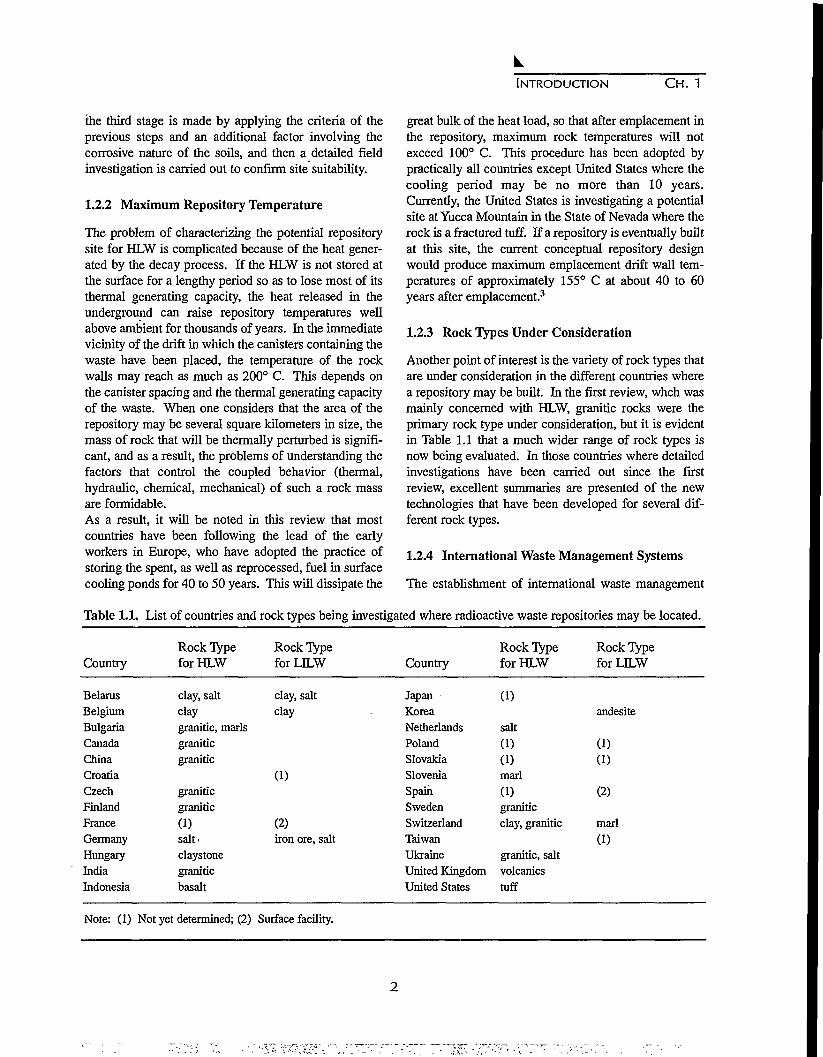
1. Introduction1.1 List of countries and rock types being investigated where radioactive waste
repositories may be located 2
2. Belarus2.1 Specific activities of radionuclides 6
3. Belgium3.1 Data on radioactive waste types in Belgium 11
6. China6.1 Nuclear power plants of China 526.2 Crustal characteristics in western Gansu Province, China 60
7. Croatia7.1 List of comparative criteria and their weighting factors 687.2 Application of comparative criteria 73
11. Germany11.1 Recommendations for research I l l
13. India13.1 List of attributes considered in Stage 1 12613.2 Compressive strength of heat treated granite 12913.3 Effect of temperature on Young's modulus 130
14. Indonesia14.1 Permeability measurements for Genting Island 134
15. Korea16.1 Cavern and disposed waste volumes 15016.2 Radionuclide Inventory 15016.3 Waste inventory 15016.4 Summary of log-hydraulic conductivity distributions 15216.5 Results of the base-case pathline calculation 15416.6 Calculated buffering times for caverns 15616.7 Source-term submodels within MASCOT system model 157
xv

17. Netherlands17.1 Resolution of various geophysical reconnaissance methods with depth in meters 167
18. Poland18.1 Waste classifications 184
20. Slovenia20.1 Exclusionary criteria of Step One 19820.2 The main gelogical characteristics of the sites 200
24. Taiwan24.1 Information on nuclear power plants in Taiwan 23224.2 Total amount of LLRW in Taiwan 23524.3 Important operating parameters of the Volume Reduction Center 23624.4 Taipower's overall program plan for LLW final disposal 238
xvi
ACKNOWLEDGEMENTS
The cover illustration prepared by Atomic Energy of Canada Limited shows a schematic drawing of theirUnderground Research Laboratory at Pinawa, Manitoba. It is used with permission of Atomic Energy of CanadaLimited.
This work was supported, in part, by the Director, Office of Civilian Radioactive Waste Management, U.S.Department of Energy, through Memorandum Purchase Order EA9013MC5X between TRW Environmental SafetySystems, Inc. and the Ernest Orlando Lawrence Berkeley National Laboratory, under Contract No. DE-AC03-76SF00098. We would also like to thank Dr. J. Russell Dyer for his encouragement and support of this second world-wide review.
The report, "Geoscientific and rock mechanical activities for the radioactive waste repositories in Germany: Keyissues, status and future plans," by M. Langer and H Rothemeyer is reprinted from: Aubertin, M., F. Hassani and H.Mitri (eds.). Tools and techniques in rock mechanics - Proceedings of the 2nd North American Rock MechanicsSymposium, NARMS '96, Montreal, Quebec, 19-21 June 1996, 2050 pp. 2 volumes, Hfl.245/US$150. Please orderfrom: A.A. Balkema, Old Post Road, Brookfield, Vermont 05036 (telephone: 802-276-3162; telefax: 802-276-3837).
The very careful work of Ms. Jackie Gamble and Ms. Maria Fink on design and production of this report is grate-fully acknowledged. We also wish to acknowledge the excellent work of Mr. Flavio Robles on design of the coverand select other graphics of this review.
xvn

XV111

CHAPTER 7
INTRODUCTION TO SECOND WORLD WIDE REVIEW OF GEOLOGICALPROBLEMS IN RADIOACTIVE WASTE ISOLATION
P. A. Witherspoon
University of California and E. O. Lawrence Berkeley National LaboratoryBerkeley, California 94720, U.S.A.
1.1 INTRODUCTION
The first world wide review of the geological problemsin radioactive waste isolation was published byLawrence Berkeley National Laboratory in 1991'. Thisreview was a compilation of reports that had been sub-mitted to a workshop held in conjunction with the 28thInternational Geological Congress that took place July9-19,1989 in Washington, D.C. Reports from 15 coun-tries were presented at the workshop and four countriesprovided reports after the workshop, so that materialfrom 19 different countries was included in the firstreview.
It was apparent from the widespread interest in this firstreview that the problem of providing a permanent andreliable method of isolating radioactive waste from thebiosphere is a topic of great concern among the moreadvanced, as well as the developing, nations of theworld. This is especially the case in connection withhigh-level waste (HLW) after its removal from nuclearpower plants. The general concensus is that an adequateisolation can be accomplished by selecting an appropri-ate geologic setting and carefully designing the under-ground system with its engineered barriers.
There is the additional problem of isolating low- andintermediate level waste (LILW). Significant quantitiesof LILW are generated from various sources, and whilethey are not as long lived and do not pose the same levelof difficulty as HLW, they constitute another, but impor-tant, problem for the nuclear industry.
Much new technology is being developed to solve theproblems of waste isolation, and there is a continuingneed to publish the results of new developments for thebenefit of the international nuclear community. Thus, itwas decided that after a five-year interval, it would bedesirable to gather material on the latest developments
and publish another review on the geological problemsof radioactive waste isolation. As shown in Table 1.1,this second review contains reports from 26 countries.
1.2 SOME HIGHLIGHTS FROM THE SECOND REVIEW
1.2.1 Characterizing the Repository Site
Although no repository for HLW has yet been put inoperation, significant progress has been made on thissubject since the publication of the first review. Todecide where to locate a repository for HLW requires alengthy and detailed process of characterizing the rockmass in which the waste will be placed. Some countrieshave been working on this process for over ten years,and the wide variety of technologies that are describedin this review reflects the fact that, in general, eachcountry has its own internal constraints to satisfy. Theprocess of site characterization can be significantly dif-ferent depending on the particular type of rock that hasbeen selected as a potential repository site.
The problem of locating a repository for LILW is not asdifficult as for HLW, primarily because there is no heatrelease from the waste to cause temperature problems.Furthermore, a number of the reports in this reviewdescribe some well thought out procedures that havebeen developed to handle LILW. For example, inSlovenia2, the siting process has been divided into foursteps. In the first step, unsuited areas are omitted fromconsideration on the basis of certain exclusionary crite-ria. In the second step, the remaining acceptable areasare further reduced to potential sites according to landuse, water resources, seismic and geological criteria. Inthe third step, several of the most suitable of the poten-tial sites are chosen by comparing their locations on thebasis of population, economic feasibility, transport,ecology, and public acceptance. In the final fourth step,a comprehensive analysis of the most suitable sites from
INTRODUCTION CH. 1
the third stage is made by applying the criteria of theprevious steps and an additional factor involving thecorrosive nature of the soils, and then a detailed fieldinvestigation is carried out to confirm site suitability.
1.2.2 Maximum Repository Temperature
The problem of characterizing the potential repositorysite for HLW is complicated because of the heat gener-ated by the decay process. If the HLW is not stored atthe surface for a lengthy period so as to lose most of itsthermal generating capacity, the heat released in theunderground can raise repository temperatures wellabove ambient for thousands of years. In the immediatevicinity of the drift in which the canisters containing thewaste have been placed, the temperature of the rockwalls may reach as much as 200° C. This depends onthe canister spacing and the thermal generating capacityof the waste. When one considers that the area of therepository may be several square kilometers in size, themass of rock that will be thermally perturbed is signifi-cant, and as a result, the problems of understanding thefactors that control the coupled behavior (thermal,hydraulic, chemical, mechanical) of such a rock massare formidable.As a result, it will be noted in this review that mostcountries have been following the lead of the earlyworkers in Europe, who have adopted the practice ofstoring the spent, as well as reprocessed, fuel in surfacecooling ponds for 40 to 50 years. This will dissipate the
great bulk of the heat load, so that after emplacement inthe repository, maximum rock temperatures will notexceed 100° C. This procedure has been adopted bypractically all countries except United States where thecooling period may be no more than 10 years.Currently, the United States is investigating a potentialsite at Yucca Mountain in the State of Nevada where therock is a fractured tuff. If a repository is eventually builtat this site, the current conceptual repository designwould produce maximum emplacement drift wall tem-peratures of approximately 155° C at about 40 to 60years after emplacement.3
1.2.3 Rock Types Under Consideration
Another point of interest is the variety of rock types thatare under consideration in the different countries wherea repository may be built. In the first review, whch wasmainly concerned with HLW, granitic rocks were theprimary rock type under consideration, but it is evidentin Table 1.1 that a much wider range of rock types isnow being evaluated. In those countries where detailedinvestigations have been carried out since the firstreview, excellent summaries are presented of the newtechnologies that have been developed for several dif-ferent rock types.
1.2.4 International Waste Management Systems
The establishment of international waste management
Table 1.1. List of countries and rock types being investigated where radioactive waste repositories may be located.
Country
BelarusBelgiumBulgariaCanadaChinaCroatiaCzechFinlandFranceGermanyHungaryIndiaIndonesia
Note: (1)
Rock Typefor HLW
clay, saltclaygranitic, marlsgraniticgranitic
graniticgranitic
(1)saltclaystonegraniticbasalt
Not yet determined; (2)
Rock TypeforLILW
clay, saltclay
(1)
(2)iron ore, salt
Surface facility.
Country
JapanKorea
NetherlandsPolandSlovakiaSloveniaSpainSwedenSwitzerlandTaiwanUkraineUnited KingdomUnited States
Rock Typefor HLW
(1)
salt
(1)(1)marl
(1)graniticclay, granitic
granitic, saltvolcanicstuff
Rock TypeforLILW
andesite
(1)(1)
(2)
marl
(1)

INTRODUCTION CH. 1
systems has been suggested in the past and a number ofstudies has been undertaken4'5'6-7 to address the inherentdifficulties associated with the disposal of limitedamounts of HLW exclusively within national borders.Such a system would be set up to accept and manageradioactive waste from countries with small nuclearenergy programs and relatively small volumes of HLW.Bredell and Fuchs8 and Lin9 have recently discussed thefeasibility of such systems, from technical, economical,institutional and ethical viewpoints.
The feasibility of an international waste managementsystem is not discussed in detail in any report of this sec-ond review, but as one reads of the activities in thesmaller counties (e.g., Switzerland10, Taiwan11,Ukraine12) it is clear that each one is becoming aware ofa difficult situation in developing a viable program tohandle the problems of isolating HLW. A somewhat dif-ferent aspect of the need for an international facility maydevelop in Indonesia13 because this archipelago is oneof the regions of the world with active volcanisim.
The need to consider international waste managementsystems has been discussed in a recent editorial byIssler14, who raises some important arguments. Fromthe economic standpoint, countries with relatively smallnuclear energy programs and relatively small volumesof HLW are faced with solutions that are essentiallyuneconomic. A large proportion of the disposal costs isindependent of waste volume, particularly those relatedto concept development, site selection and characteriza-tion and, to a large extent, construction and operation ofthe facility. The costs of site characterization can bevery large. For example, the cost of the total effort tocharacterize the HLW site at Yucca Mountain in theUnited States is currently about $2.5 billion15. This isatypical of costs in Europe, but it serves as an upperbound to illustrate the magnitude of costs associatedwith this complex problem.
From the practical standpoint, it may be very difficultfor small countries to find a HLW repository site that issatisfactory geologically and, at the same time, can sat-isfy planning restrictions. On the other hand, the geo-logical situation in a particular country may not befavorable, and the country has no choice except to storethe waste for an indefinite period. In this respect, region-al repositories could provide a safer solution. And fromthe technical standpoint, the more advanced countriescan help others that are disadvantaged by lack of infra-structure, restricted financial means, insufficient techni-cal capacity, or lack of relevant know-how.
Issler has a very good point that puts the situation incontext. The United States is planning only one or tworepositories for its HLW. Europe, which is comparablein geographic area, has 18 of the 26 countries on Table1.1, that need disposal facilities. Should 18 nationalrepositories for HLW be constructed, or do not the eco :
nomic and geologic considerations indicate that two orthree regional facilities would suffice? It is understand-able that acceptance of international solutions, particu-larly in the host countries, will be difficult to achieve,but the option of international waste management sys-tems should be kept open and needs careful considera-tion.
REFERENCES
1. Geological Problems in Radioactive Waste.Isolation: A World Wide Review, LawrenceBerkeley Laboratory Report, LBL-29703, Ed. RA.Witherspoon, 233 pp., 1991.
2. Petkovsek, B., M. Dusan and I. Osojnik, Geologicalaspects of site selection for low and intermediatelevel radwaste repository in Slovenia, this volume.
3. Dyer, J.R. and M.D. Voegele, High-level radioac-tive waste management in the United States,Background and Status: 1996, this volume.
4. Kiihn, K., Are we ready to construct and operate anunderground repository?, Proceedings Symposiumon Siting, Design, and Construction ofUnderground Repositories for Radioactive Wastes,IAEA, Vienna, Austria, Mar. 3 - 7,1986.
5. International Approaches on the Use of RadioactiveWaste Disposal Facilities, OECD, Report, Paris,France, p. 13, 1987.
6. Lin, W., A global nuclear waste repository, Forum,EOS Transactions, American Geophysical Union,69,18, p. 561, 1988.
7 Technical, Institutional and Economic Factors forDeveloping a Regional Repository, IAEA Report,Vienna, Austria, Nov. 28 - Dec. 2,1994.
8. Bredell, P.J. and H.D. Fuchs, An approach to inter-national high level radioactive waste management,High Level Radioactive Waste Management,Proceedings Seventh Annual InternationalConference, Las Vegas, NV, pp. 486-488, Apr. 29 -

INTRODUCTION CH. 1
May 3,1996.
9. Lin, W., International high-level radioactive wasterepositories, High Level Radioactive WasteManagement, Proceedings Seventh AnnualInternational Conference, Las Vegas, NV, pp. 492-493, Apr. 29 - May 3,1996.
10. McKinley, I.G. and C. McCombie, High-levelradioactive waste management in Switzerland:Background and status 1995, this volume.
11 Tsai, CM. and D.S. Liu, Low level radioactivewaste management in Taiwan, this volume.
12. Khrushchov, D.P. and V.M. Starodumov, Pro-gramme and results of initial phase of radioactivewaste isolation in geological formations in Ukraine,this volume.
13. Imardjoko, Y.U., H.B. Santosa, Sunarno, N.Prabaningrum, A. Muharini, E. Wijayanti, and M.Adiartsi, Critical data required to potentially inves-tigate Genting Island as a high-level radioactivewaste repository site facility in Indonesia, this vol-ume.
14. Issler, H., International radwaste collaboration -View from a small country, Editorial, NuclearEurope Worldscan, 3-4,1996.
15. Witherspoon, P.A., R.A. Freeze, F.A. Kulacki, J.N.Moore, F.W. Schwartz, and Y.C. Yortsos, PeerReview Report on Thermohydrologic Modeling andTesting Program, Appendix D, U.S. Department ofEnergy Determination of the Use of the Results ofthe Peer Review Report on the ThermohydrologicModeling and Testing Program, Yucca MountainSite Characterization Project, August, 1996.

CHAPTER 2
DISPOSAL OF RADIOACTIVE WASTE IN BELARUS AND COMPLICATIONSFROM THE CHERNOBYL DISASTER
Anatoly V. Kudelsky
Institute of Geological Sciences of the Academy of Sciences of BelarusZhodinskaya Street 7, Minsk 220141, Belarus
2.1 INTRODUCTION
A very large area of the Republic of Belarus wasexposed to radioactive contamination as a result of theaccident at the Chernobyl nuclear power plant on April26, 1986. Following the accident, the reactor whichcontained 190.2 t of nuclear fuel, released 1.85 x 10¹⁸
Bq of radiation into the environment, of which approxi-mately 70% fell within the territory of Belarus. Thereleased composition included a large amount ofradionuclides of iodine, cesium, cerium, barium, stron-tium, plutonium, etc.
As shown in Figure 2.1, the prevailing winds carriedcontamination as much as 300 km away from the plantto the north and to the west in Belarus. A total of 46,450
LATVIA
LITHUANIA
km2 (23% of the country) was contaminated, an areathat was originally inhabited by 2.1 million people (over20% of the population). The contamination has affect-ed 1.8 million hectares of agricultural lands, of which264,000 hectares have been excluded from use. The ter-ritory of the Polessie State Radioecological Reserve(131,400 hectares) has been turned into a "plutoniumreservation" and is practically excluded from usebecause of the high levels of contamination.
Although Belarus has no nuclear power plant producingspent fuel, it has some very serious problems in devel-oping appropriate remediation measures to collect andisolate the many kinds of contamination that are spreadthroughout the affected areas (Fig. 2.1).
•P . Miuck • m )
RUSSIA
POLAND ,L-.
ChernoByE
Figure 2.1. Areas in the Republic of Belarus contaminated by radionuclides from Chernobyl.
5

BELARUS C H . 2
2.2 DECONTAMINATION WASTE AND BURIAL
METHODS
The Belarus territory has received a great amount ofradionuclide fallout over a significant percentage of itsarable land, and although the contaminated industrialand other objects are numerous and widespread, theactivity of the decontamination products (DP) is ratherlow, of the order of 10"6 to lO"8 Ci/kg. In view of thespecific character of the releases from Chernobyl andconsidering the DP and its associated materials as onecategory of radioactive waste, the National Committeefor Radioactivity Protection (NCRP) of Belarus hasadopted the levels of specific activity as shown in Table2.1.
Table 2.1. Specific activities of radionuclides.
Radionuclide
Cesium-137Strontium-90Other beta-emittersPlutonium and othertransuranic elements
Specific ActivityBq/kg
8.5xlO3
3.7xlO4
7.4xlO4
3.7xlO2
An effective program of decontamination outside the30-km zone (plutonium contamination zone aroundChernobyl) was carried out in the period 1986-1988. Asa result, 12 million m2 of exterior surfaces of buildingsand other constructions were cleaned, 13.3 million m3 ofcontaminated ground were removed and buried, and7570 old buildings were demolished and buried. TheseDP were stored far from populated areas, mainly inunprepared sites (such as flat areas, gullies, sinks, oldquarries, etc.). About 980,000 m3 of DP and other con-taminated refuse are located in 69 partially equippedrepositories and five makeshift burial grounds. All thesesites are constructed in zones where the 137Cs activity ofthe soils is 15 Ci/km2 and above; the gamma radiationexposure dose rates in the storage sites vary from 0.03 to0.23 mR/h. The cumulative activities total 1.9 TBq for137Cs, 0.14 TBq for 90Sr, and 2.6 TBq for 239,240pu
Most of these burials are ecologically unsuitable, andthe radioactive wastes placed there need to be reburied.A concept and strategy for reburial have been devel-oped, and sites with a suitable geology and geomor-phology for constructing repositories have been select-ed. When selecting sites for DP repositories, the fol-
lowing factors have been considered:
• Location of testing grounds in evacuation zones andobligatory evacuation of people from areas where theactivity exceeds 40 Ci/km2;
• Correspondence of the geologic and hydrogeologicconditions of the locality to the requirements for saferadioactive waste isolation;
• Hydrogeologic conditions of the territory with refer-ence to flooding and seasonal water levels, areas sub-jected to flooding, etc.;
• Structure of atmospheric circulation and seasonalwind patterns in relatively uncontaminated areas andpopulated areas; and
• DP transportation routes, quality of major and sec-ondary highway routes (near cities), dust generationduring loading, transportation, etc.
A model to forecast the migration of radionuclides awayfrom waste repositories has been developed for recom-mended objects with given migration parameters.
2.3 PROGRAMME FOR DEEP DISPOSAL OF
RADIOACTIVE WASTE
In the context of the government programme to con-struct nuclear power plants in the future, sites for theirlocation have been selected, and a preliminary investi-gation of geological conditions has been carried out tolocate potential sites for repositories for high- and medi-um-level radioactive wastes. Three rock types havebeen recognized as potentially being able to provide sat-isfactory conditions for radioactive waste disposal: (a)the crystalline basement, (b) salt beds, and (c) thickdeposits of monomineral clays.
As shown on Figure 2.2, the territory of Belarus hasbeen subdivided into zones showing various conditionsto be considered in selecting sites:
• Areas marked Zone I are where the depth to base-ment ranges from 0.0 to 0.4 km and where conditionsare considered very promising for engineering andconstructing repositories in basement crystallinerocks;
• Areas marked Zone II are where the depth to base-ment ranges from 0.4 to 0.6 km and where conditionsdo not show much promise for repositories in base-ment crystalline rocks;
• Areas marked Zone HI are where the depth to base-ment ranges from 0.6 to 1.5 km and where conditions

BELARUS CH. 2
Figure 2.2. Geological division of Belarus into zones in accordance with conditions for medium- and high-levelradioactive waste isolation. Legend: 1 - isolines showing depth to crystalline basement (km); 2 - tec-tonic faults penetrating through the sedimentary cover; 3 - boundaries of zones with different conditionsand potential for waste isolation. Symbols for regions with geologic structures considered as primarycandidates for repositories: 4 - crystalline basement of Bobovnya, Slonin and Mikashevichy uplifts; 5 -salt diapir domes of: a - Novaya Dubrova, b - Zarechie, c - Kopatkevichy, d - Konkovichy, e -Shestovichy; and 6 - palygorskite clay beds of Pripyat Graben. Other symbols: 7 - boundaries of dis-tricts; 8 - frontier of Belarus; and 9 - Chernobyl nuclear power plant.
show very little promise for radioactive waste repos-itories; and
• The area marked Zone IV is the Pripyat Graben thatis considered to have highly promising geologicalstructures for waste repositories in: (a) stratified sal-iferous formations of Middle and Upper Devonian,(b) domed salt diapirs of the Upper Salt strata, aswell as in (c) palygorskite clay beds of UpperDevonian strata.
Crystalline rocks are exposed or overlain byAnthropogene deposits of limited thickness within theCentral-Belarussian massif, Ukrainian shield andMikashevichy uplift (horst). The Central-Belarussian
massif with the Bobovnya uplift of granitic rocks (100-170 m in thickness) and the Slonim uplift of granuliticcomplexes with blastomilonite show the greatestpromise for a site for radioactive waste isolation.
Salt formations cover a vast area (23,000 km2) withinthe Pripyat Graben and are represented by two Upper-Devonian salt strata: (a) Upper Frasian (up to 1100 mthick), and (b) Upper Famennian (up to 3000 m thickzones of diaparisim) separated by terrigenous-carbonatestrata. Salt formations occur in zones of diapirism in adepth range of 300 to 400 m and have the potential assites for waste disposal (Novaya Dubrova, Zarechye andKopatkevich uplifts on the northwest, and Konkovichy
7

BELARUS CH. 2
and Shestovichy uplifts, on the southwest side of the itories.graben).
AcknowledgmentsLarge deposits of palygorskite clays are found in thePripyat Graben at depths of 80 to 120 m, and with thick- These investigations were sponsored by the Statenesses of as much as 140 to 150 m, they are of particu- Committee of the Republic of Belarus on the problemslar interest as potential sites for radioactive waste repos- of the Chernobyl consequences.
8

CHAPTER 3
GEOLOGICAL RADWASTE DISPOSAL IN BELGIUM
RESEARCH PROGRAMME, REVIEW A N D OBJECTIVES
Bernard Neerdael
SCK-CEN , HADES Project, Waste and Disposal Research UnitBoeretang 200, B2400 M01, Belgium
Executive Summary. In the early seventies, SCK-CENlaunched a research programme on the geological dis-posal of long-lived radioactive waste. Investigationswere concentrated on argillaceous formations becauseof their abundance at various depths in some parts ofBelgium, their expected favourable properties and thevirtual absence of salt and/or unfracturated hard rockformations in the country. Among the argillaceous for-mations, the Tertiary "Boom clay" layer was tentativelyselected for site characterization studies. In this firstphase, the Research and Development programme con-sisted of laboratory studies on clay core samples andobservations on the geology and hydrology of the area.The initial results were very promising with regard tosorption properties of the potential host rock, its chemi-cal stability, permeability, etc.
Early in the programme (1980), an underground labora-tory (HADES) was constructed in the clay at the Molsite; a tunnel, 35 m long and 3.5 m in diameter providesa large number of access possibilities to the clay forma-tion, at a depth of 223 m. The first objectives were relat-ed to the technical feasibility of gallery excavations inplastic clay under high lithostatic pressures and to theevaluation of the compatibility of vitrified HLW andcandidate container materials with the clay, in close toreal conditions. In 1988, an additional 60 m long driftwas built for integrated tests, e.g. the impact of temper-ature and radiation. In the meantime, much experiencehas been gained on sampling of fluids and solids, in thecharacterization of clay and waste forms; an importantscientific data base is now available at SCK-CEN,specifically for vitrified waste and "Boom clay."
This formation - and site specific approach - allowedSCK-CEN to collect, in a short period of time, valuableresults and input data for required modelling work.
Some preliminary observations could be made:
• using conventional civil engineering technology, it istechnically feasible to drive horizontal galleries inplastic clay, at a depth of more than 200 m, with aninternal diameter of at least 3.5m, without specialground conditioning, such as freezing;
• using available experimental data about permeabilityand retention properties of the host rock (Boomclay), preliminary safety assessments were carriedout for many scenarios from natural evolution toimportant disruption. For the reference mix of repro-cessing waste (HLW, MLW, hulls) from a 40 ynuclear programme in Belgium, the highest calculat-ed dose to population, for a normal evolution scena-rio and water well pathway, is of the order of 3xlO"7
Sv/a, which can be compared with a dose constraintof 10"4 Sv/a, in use in several countries; these doseswould occur after a period of about 60,000 years.
• stabilizing factors in the Boom clay are its cationicexchange capacity, the strong reducing conditionsdue to finely dispersed pyrite and humic materialsintimately associated with the clay minerals and aslightly alkaline environment caused by the occur-rence of carbonates; and
• the methodology for risk assessment was establishedand tested in the framework of an internationalbenchmark exercise in cooperation with theEuropean Commission and the Nuclear EnergyAgency of the OECD.
Observations and earlier assessments also illustrateremaining areas of uncertainty which require comple-mentary R&D or new studies and demonstrations.Furthermore, the validity of present evaluations and pre-liminary conclusions, mainly in view of the very longterm safety, will benefit from an iterated validation of

BELGIUM C H . 3
models and even comparisons with studies on naturalanalogues.
3.1 INTRODUCTION
In the present context, the R&D programme ofSCK-CEN on radioactive waste management is focusedon the characterization of conditioned waste and itsunderground disposal in geological formations.
Although in the past (1960 to -1985), SCK-CEN hasrun several projects on waste treatment and conditioning(mainly low-level and alpha-bearing waste), very little isstill being pursued in this area, given the commercialavailability of industrial processes and the fact that thewaste treatment and conditioning has been entrusted toa separate company, BELGOPROCESS. However, thistrend may have to be adjusted some time in the futurefor reasons of optimization and the development of newwaste types resulting from e.g decommissioning and/orsite restoration programmes.
With regard to characterization of conditioned waste,the programme aims at quality control (verification ofcompliance with contractual quality criteria), character-ization of the "source term," which includes studies ofcorrosion phenomena and compatibility of the condi-tioned waste form, and its package with the intendedgeological environment. Attention also has to be paid to"acceptance criteria" since the total radiological capaci-ty of the repository is obviously limited, and non-radio-logical factors (e.g temperature and residual thermalcapacity of the waste and potentially interfering compo-nents) may enhance the mobility of radionuclides in therepository formation. Furthermore, the occurrence ofchemo-toxic components in conditioned waste or pack-ages deserves a minimum of attention.
With regard to geological disposal, the R&D pro-gramme, initiated by SCK-CEN, deals mainly with thedisposal of vitrified high-level waste from reprocessingand other alpha-bearing wastes. Other types of waste areto be considered in the future such as, for example, nonreprocessed spent fuel or spent MOX fuel since it isclear that, even if reprocessing remains the referencescenario, at least some spent fuel is not suited for indus-trial reprocessing.
The R&D programme on disposal proceeds stepwiseand cautiously since options have to remain flexibleuntil adequate scientific and technical ground is avail-able to support decisions.
In the exploration of geological formations (1974) forthe implantation of a repository in Belgium and afterconsultation with the National Geological Survey, pref-erence was expressed for a deep clay formation (called"Boom clay") at and around the site of Mol. This earlypreference, resulted from a number of facts, e.g. theabsence in Belgium of any salt formations, the highlyfractured nature of most hard rock formations, the nat-ural retention capacity of clay, and the fact that majornuclear facilities were already installed in the Mol area.Consequently, R&D and assessment studies becamemostly site-specific or at least formation-specific, with-out anticipating the conclusions of a more detailed siteselection procedure.
The Boom clay belongs to the Rupelian formation andis underlain by the Berg sands (Rupelian aquifer) andoverlain by the Neogene aquifer. These two water bear-ing formations are not considered as barriers, althoughthey could have good sorption properties for theradionuclides. Rather early in the programme (1980), anunderground laboratory was constructed in the clay atthe Mol site at a depth of 223 m. The underground lab-oratory was intended to evaluate the technical feasibili-ty of such a construction and to become an in-situ facil-ity for performing tests in close to real conditions with-in the High Activity Disposal Experimental Site(HADES) project.
The current R&D programme is focused on site charac-terization (mechanical, physicochemical, and hydrogeo-logic properties) and performance assessments.Understanding the basic phenomena which control theretention and/or mobility of radionuclides in the clayreceived high priority. A first interim safety report(SAFTR) was produced for the Authorities in 1989. Themain conclusion was the absence of counter-indicationsagainst the principle of disposal in clay. The next pre-liminary safety report is to be submitted around 1998and is meant to be an important milestone in the selec-tion, or decision making, process.
For the near future, investigations on basic phenomenaof physical chemistry and geohydrology are to be con-tinued; in addition, a number of areas may require muchmore study and investigation such as:
• impact of radiation and heat on retention/mobility ofradionuclides in clay; these near-field effects mayaffect important factors such as the length of coolingtime in surface storage facilities prior to transfer intothe repository and/or the conceptual design of the
10

BELGIUM C H . 3
repository;• influence or significance of non-radioactive compo-
nents in the anaerobic environment of the repository(e.g decomposition products of organic materials). Incase of adverse effects, they might lead to the con-sideration of alternative conditioning processes,depending on the acceptance criteria for packagedwaste; and
• other issues are to be considered as well, e.g positionwith regard to retrievability, reduction of uncertain-ties with regard to some major characteristics and tothe time scales applicable to geological disposal.
The above programme items require a major extensionof the present underground facility to perform largerscale integrated in-situ demonstration tests. This impor-tant decision has been recently taken and after 1998 willlead to doubling the present capacity.
3.2 THE HADES PROGRAMME AT SCK-CEN
The R&D programme on geological disposal was initi-ated in 1974 by SCK-CEN and received scientific andfinancial support from the European Commission fromthe very beginning. Since 1985, it has been heavily sup-ported by the National Radioactive Waste Agency(ONDRAF/NIRAS), which is in charge of the imple-mentation of the disposal programme.
With a total installed nuclear power of 5.5 GWe and a40-year operational period for the Belgian nuclearpower plants, the volume of waste to be produced oflow, medium and high activity can be estimated to be150,000 m3,39,000 m3 and 4000 m3, respectively. Thesevolumes do not yet include the decommissioning waste.
The first category of waste contains small quantities ofshort- or medium-lived radionuclides (half-life notexceeding thirty years); the current option is to disposethis waste at the surface; shallow land burial is consid-ered in Belgium as the reference solution but will not beexamined in the present document. Earlier disposalstudies resulted in a report submitted by the waste man-agement authority (NIRAS/ONDRAF) in 1993 to anational advisory scientific commission; they are beingupdated and extended according to the recommenda-tions of this commission.
Two other types of waste are considered in Belgium forunderground disposal:
• alpha-contaminated waste (concrete or bitumen
matrix) containing significant quantities of medium-lived radionuclides (half-life exceeding 30 years); itresults from specific fuel cycle operations (spent fuelreprocessing, fuel assembly manufacturing) and doesnot generate heat; and
• vitrified heat-emitting waste (glass matrix) contain-ing a mixture of short- or medium-lived radionu-clides in high concentrations, and long-lived radionu-clides which are usually alpha emitters. It generates asignificant heat power, owing to the fission productscontent.
Table 3.1 presents some more details on these wastetypes and volumes.
Table 3.1. Data on radioactive waste types in Belgium.
Waste Type
HEAT EMITTING WASTECogema high-level wasteCogema cladding wasteEurochemic high-level waste
ALPHA WASTE & OTHERTechnological alpha wasteMLW concentratesReactor operating wasteCoprecipitation sludgeEurochemic MLW concentratesMox production waste
Matrix
glassconcrete
glassTotal
cementconcreteconcretebitumenbitumenconcrete
Total
VolumeTotal (m3)
7842,860265
3,909
8,41920,4302,7243,3102,7651,353
39,001
It is assumed in the present reference scenario that theoperation of a repository for underground waste dispos-al could start in 2035 to last until 2070/2080 (closurephase). This requires, for vitrified waste, a temporarysurface storage of about 50 years allowing the heat out-put to be significantly reduced. This limited heat outputin the repository is intended to produce temperatures notexceeding 100° C in the host clay at the container/clayinterface and is one of the basic assumptions for the def-inition of the R&D programme and associated process-es to be considered.
3.2.1 Historical Review of Hades Program
Early studies on potential host formations for geologicaldisposal have indicated that, in Belgium, clay and shale
11

BELGIUM C H . 3
layers can be taken seriously into consideration. One ofthe potential formations which was identified is theBoom clay at the Mol-Dessel site situated in northeast-ern Belgium, where the SCK-CEN and other nuclearfacilities are located. The following guidelines for theprovisional selection (for experimental purposes) of theBoom clay layer were considered: the anticipated futurestability of this 30 million year old formation as well asits depth, thickness, relative homogeneity and sorp-tion/retention capacity (Heremans and Baetsle, 1978).
The research programme was started about 20 years agoby SCK-CEN, which concentrated its activities on veri-fication of basic phenomena, safety and technical feasi-bility. Several partners from Europe and abroad joinedthe programme during the second decade and, throughtheir own competence, contributed to the integration ofdifferent scientific and technological skills andapproaches (Bonne and Collard, 1992).
3.2.2 Approach and Major Achievements DuringFirst Two Decades of Programme.
Beside the selection of the formation (and experimentalsite), the first decade (1974-1984) was dedicated to ver-ify whether the characteristics and properties of theBoom clay layer were really promising for hosting ageological repository.
The first drillings were performed on the SCK-CEN sitefrom 1975 onwards; and analyses of core samples weremade to determine lithological, chemical, mineralogi-cal, ion exchange and geomechanical properties ofBoom clay and, in some cases, of the surrounding stra-ta. Geohydrological studies were undertaken; a prelimi-nary repository design and a probabilistic risk assess-ment methodology were developed. Simultaneously, acatalogue of all potential formations occurring in thecountry was established. From these studies, it was con-cluded that the Boom clay satisfied the expectations;this plastic material has good sorption capacities andprovides very low permeability and low but sufficientheat conductance. It is sufficiently thick and homoge-neous and it is chemically and mineralogically stable.Preliminary experiments on corrosion/heat transfer wereperformed in parallel from an open clay pit inTerhaegen, near Antwerp.
The next step was to demonstrate that it was technicallyfeasible to build a repository in such a plastic materialand to strengthen our capabilities in the area of safetyassessment; in the latter, a collaboration with JRC Ispra
was an important feature (D'Alessandro and Bonne,1981).
An underground research laboratory (URL) was builtaccording to specifications which were based on verypessimistic hypotheses (afterwards found to be unrealis-tic) about the plasticity and perviousness of the Boomclay. For example, the freezing technique was not onlyused in sands to sink the shaft through these water-bear-ing formations but also in clay to lower the anticipatedconvergence rate.
The approach became fully site and formation specific;the site of Mol was placed in a larger geohydrologicalcontext, extending the regional observation network ona 2,000 km2 area around Mol. Both clay and surround-ing geologies were intensively investigated from variousperspectives (geochemical, geomechanical, hydrologi-cal and geophysical). Due to an increasing amount ofavailable information, the Boom clay became progres-sively a reference case.
For the critical issue of geomechanics in clay, collabo-ration was started with ANDRA, the French waste man-agement agency; the digging of a small experimentalshaft and gallery in non-frozen clay demonstrated thepossibility of excavating and tunneling in the plasticBoom clay at such a depth.
During the second decade (1984-1994), the URLbecame fully operational; several experimental set-upswere installed in clay for studies on corrosion,hydraulics, migration and geomechanics. A new andchallenging field of demonstration was opened with theCEC programme on demonstration and pilot facilities.The HADES URL was extended by tunneling a test driftfor demonstration purposes as illustrated in Figure 3.1.
This facility, now called URF (Underground ResearchFacility,) consists of 100 metres of galleries lined withcast-iron, concrete or steel ribs, providing direct accessto the clay mass. In particular, the test drift offered theopportunity to perform large scale integrated tests underconditions close to those expected in and around a finalrepository.
Validation exercises for the modelling of differentprocesses were launched and extensive performanceassessment exercises were carried out, as the"Performance Assessment of Geological IsolationSystems" (PAGIS) and the "Performance Assessment ofConfinements for Medium-level and Alpha waste,"
12

BELGIUM CH. 3
CONSTRUCTION :
SHAFT : 1-10-80*2-9-82URL : 30-9-82 —15-7-83EXP. SHAFT : 29-9-83 — 18-1-84TEST DRIFT : 1-3-87*24-12-87
2«.9
Figure 3.1. The underground research facility (URF) HADES.
(PACOMA) within the framework of the E.C. Bothstudies were updated, and results were published in the"Updating 1990" (Marivoet, 1992). A methodology waselaborated with the involvement and consensus of alarge number of scientists in different member states,active in the various fields of this multidisciplinaryactivity; the broad contribution from the latter activityhad a very positive impact on confidence building.
In 1990, an international commission of experts, formedby the Belgian Secretary of State for Energy, evaluateda Safety Assessment and Feasibility Interim Report(SAFER.) on the geological disposal of waste preparedby NIRAS/ONDRAF (1989); the results of the researchcarried out by SCK-CEN on final disposal in Boom claywere the main contribution to this report.
These successive actions confirmed the choice of theclay option in Belgium and the continuation of the sitecharacterization programme on the Boom clay layer atthe Mol-Dessel site as a potential host formation essen-tially for long-lived waste. They also define the R&Dpriorities developed in the current programmes on thedifferent components of the disposal system. As a resultof these continuing interactions, tangible progress hasbeen made through improvements in the SCK's charac-terization programme, e.g. more recently regarding thestudy of the performance of the engineered barriers inthe near-field. Present and future developments are
detailed in the next chapters.
3.3 OBJECTIVES AND BASIC ASSUMPTIONS OF
HADES PROGRAMME
3.3.1 Objectives
Safe disposal of radioactive waste is one of the keyissues in the environmental concerns of the nuclearindustry. In particular, the disposal of long-lived waste,specifically spent fuel and vitrified high-level wastes, isimportant. Disposal in deep geological formations is atpresent the most promising option, which requires oneto meet the following objectives:
• provide reliable data on characteristics of waste andthe geological environment;
• demonstrate the feasibility of disposal concepts e.g.in underground laboratories; and
• assess the safety and acceptability of disposal sys-tems by developing and applying validated methodsto the modelling of the various phenomena whichcontrol the release and migration of radionuclidesfrom the repository into the biosphere.
3.3.2 Methodology
In order to assess the performance of individual compo-nents of the disposal system as well as that of the inte-
13

BELGIUM CH. 3
grated system, the current R&D programme coversmainly research on basic phenomena, demonstrationtests and safety studies.
The geological disposal of long-lived waste is essential-ly based on a "multi-barrier" concept; several "engi-neered" barriers (overpack, backfill, gallery lining) areinstalled between the waste matrix itself (primary con-tainment) and the host rock. The purpose is to delay(e.g. by 500 to 1000 years) the release of activity fromthe repository structure into the geological environment.The latter time period corresponds approximately to thethermal phase of the repository. Consequently, severalcoupled effects with temperature can be avoided in thehost clay, provided the required performance of theseengineered barriers can be guaranteed.
Phenomena relevant to repository performance are gen-erally subdivided into those occurring in the near-fieldand those occurring in the far-field (geosphere). Bynear-field, one generally considers the engineeredrepository structure (including the waste packages andengineered barriers) and those parts of the surroundingrock whose characteristics have been, or could be,altered by the repository or its content (excavation, tem-perature, radiation).
Any assessment of the performance of geological dis-posal refers to a conceptual design of the repository and,in particular, to the characteristics of the near field.Information concerning the Belgian reference concept isdescribed in a separate section (see Section 3.3.4).
3.3.3 Performance of Near-Field
An essential distinction for disposal in clay, with regardto disposal in granite, consists of the requirements andobjectives of the near-field.
In hard rock, the components of the multi-barrier con-tainment and essentially the backfill material are to beconsidered as primary barriers which ensure the isola-tion of the system for the time periods required. In thiscontext, the backfill must preserve alkaline conditionsduring a very long time period in order to prevent disso-lution of key radionuclides and to provide sorptioncapacity and controlled porosity and permeability. Thehost geological formation is supposed to provide struc-tural stability, a predictable groundwater flow, and asuitable long pathway and travel time for radionuclidesto reach the biosphere.
For argillaceous formations and particularly for the
Boom clay formation, the host "rock" is the primary nat-ural barrier against radionuclide migration; it providesgood sorption capacities, very low permeability, andgiven the composition of the clay, chemically reducingconditions. The backfill has to provide geomechanicaland geochemical stability and compatibility.
3.3.4 Repository Concepts in Belgium.
We are considering for geological disposal the long-lived medium level waste (MLW), heat producing vitri-fied high-level waste (HLW) and spent fuel (SF), but forthe latter category, no detailed concept has yet beenworked out.
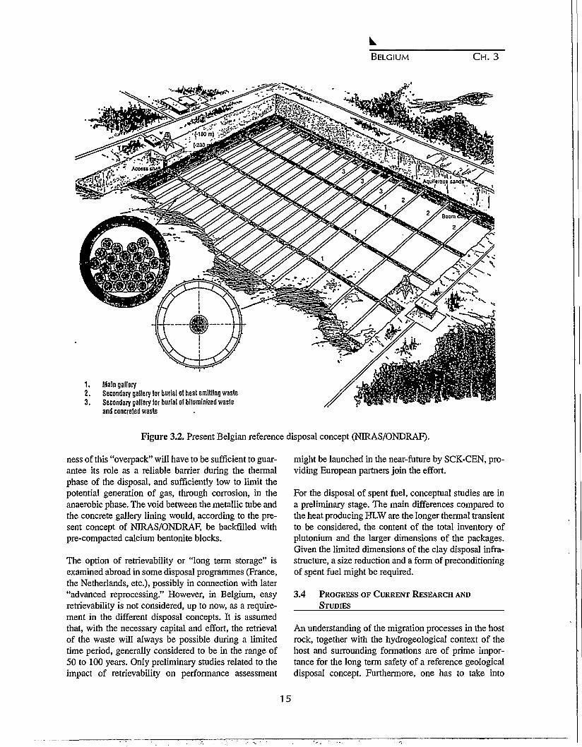
Since 1978, different repository concepts have beenconsidered for high-level and long lived radioactivewaste in the Boom clay formation at Mol. The referenceconcept, now considered by NIRAS/ONDRAF, is illus-trated in Figure 3.2. Heat producing high-level and long-lived, medium-level waste would be emplaced in sepa-rate disposal galleries. Approximate dimensions(expressed in terms of the inner diameter) for the differ-ent components are 6 m for the shafts, 4 m for the pri-mary galleries and 2 m for the HLW disposal galleries.The length of the disposal galleries would be 800 m (4sections of 200 m). Concrete would be used for liningthe shaft and galleries. The lining is designed to ensuremechanical stability during the repository's operationalphase.
For the non-heat producing long-lived MLW, the gal-leries would have an inner diameter of 3.5 m and thesection would be filled with MLW canisters, the voidsbeing backfilled, possibly with concrete (see Fig. 3.2).
The design of the HLW disposal galleries is moreadvanced (see Fig. 3.3) and will, during the next 10years, be the main subject of the PRACLAY project.The latter requires a substantial extension of the presentURF; it is managed by an Economic Interest Group(E.I.G.) where SCK-CEN and NIRAS/ONDRAF arerepresented. The PRACLAY project is a thermo-mechanical experiment intended to simulate a full scaledisposal gallery for heat-emitting waste and to quantifythe extent of the disturbance induced in the surroundingclay.
According to this concept, the HLW canisters, simulat-ed by heating elements, are assumed to be placed in longthin metallic tubes in the centre of the disposal galleries.These tubes are designed to remain intact during thethermal transient of the heat producing waste. The thick-
14
BELGIUM CH. 3
1 . Main gallery2. Secondary gallery lor burial of heat emitting waste3. Secondary gallery lor burial ol biluminized waste
and concreted waste
Figure 3.2. Present Belgian reference disposal concept (NIRAS/ONDRAF).
ness of this "overpack" will have to be sufficient to guar-antee its role as a reliable barrier during the thermalphase of the disposal, and sufficiently low to limit thepotential generation of gas, through corrosion, in theanaerobic phase. The void between the metallic tube andthe concrete gallery lining would, according to the pre-sent concept of NIRAS/ONDRAF, be backfilled withpre-compacted calcium bentonite blocks.
The option of retrievability or "long term storage" isexamined abroad in some disposal programmes (France,the Netherlands, etc.), possibly in connection with later"advanced reprocessing." However, in Belgium, easyretrievability is not considered, up to now, as a require-ment in the different disposal concepts. It is assumedthat, with the necessary capital and effort, the retrievalof the waste will always be possible during a limitedtime period, generally considered to be in the range of50 to 100 years. Only preliminary studies related to theimpact of retrievability on performance assessment
might be launched in the near-future by SCK-CEN, pro-viding European partners join the effort.
For the disposal of spent fuel, conceptual studies are ina preliminary stage. The main differences compared tothe heat producing HLW are the longer thermal transientto be considered, the content of the total inventory ofplutonium and the larger dimensions of the packages.Given the limited dimensions of the clay disposal infra-structure, a size reduction and a form of preconditioningof spent fuel might be required.
3.4 PROGRESS OF CURRENT RESEARCH AND
STUDIES
An understanding of the migration processes in the hostrock, together with the hydrogeological context of thehost and surrounding formations are of prime impor-tance for the long term safety of a reference geologicaldisposal concept. Furthermore, one has to take into
15
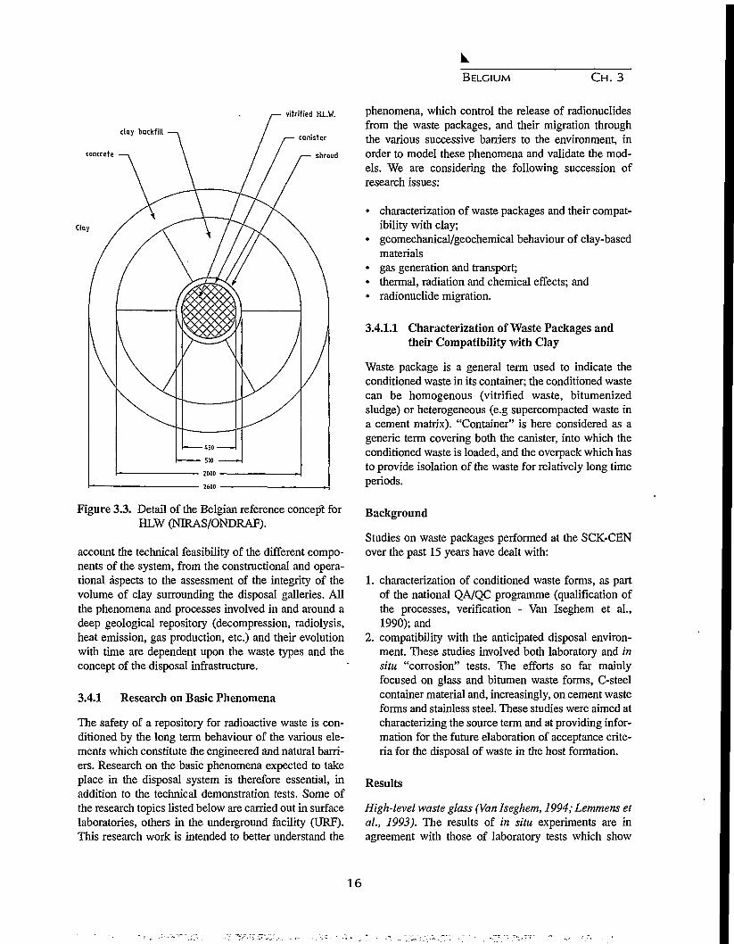
BELGIUM C H . 3
day backfill
concrete
vitrified Hi.W.
canister
shroud
Figure 3.3. Detail of the Belgian reference concept forHLW (NIRAS/ONDRAF).
account the technical feasibility of the different compo-nents of the system, from the constructional and opera-tional aspects to the assessment of the integrity of thevolume of clay surrounding the disposal galleries. Allthe phenomena and processes involved in and around adeep geological repository (decompression, radiolysis,heat emission, gas production, etc.) and their evolutionwith time are dependent upon the waste types and theconcept of the disposal infrastructure.
3.4.1 Research on Basic Phenomena
The safety of a repository for radioactive waste is con-ditioned by the long term behaviour of the various ele-ments which constitute the engineered and natural barri-ers. Research on the basic phenomena expected to takeplace in the disposal system is therefore essential, inaddition to the technical demonstration tests. Some ofthe research topics listed below are carried out in surfacelaboratories, others in the underground facility (URF).This research work is intended to better understand the
phenomena, which control the release of radionuclidesfrom the waste packages, and their migration throughthe various successive barriers to the environment, inorder to model these phenomena and validate the mod-els. We are considering the following succession ofresearch issues:
• characterization of waste packages and their compat-ibility with clay;
• geomechanical/geochemical behaviour of clay-basedmaterials
• gas generation and transport;• thermal, radiation and chemical effects; and• radionuclide migration.
3.4.1.1 Characterization of Waste Packages andtheir Compatibility with Clay
Waste package is a general term used to indicate theconditioned waste in its container; the conditioned wastecan be homogenous (vitrified waste, bitumenizedsludge) or heterogeneous (e.g supercompacted waste ina cement matrix). "Container" is here considered as ageneric term covering both the canister, into which theconditioned waste is loaded, and the overpack which hasto provide isolation of the waste for relatively long timeperiods.
Background
Studies on waste packages performed at the SCK-CENover the past 15 years have dealt with:
1. characterization of conditioned waste forms, as partof the national QA/QC programme (qualification ofthe processes, verification - Van Iseghem et al.,1990); and
2. compatibility with the anticipated disposal environ-ment. These studies involved both laboratory and insitu "corrosion" tests. The efforts so far mainlyfocused on glass and bitumen waste forms, C-steelcontainer material and, increasingly, on cement wasteforms and stainless steel. These studies were aimed atcharacterizing the source term and at providing infor-mation for the future elaboration of acceptance crite-ria for the disposal of waste in the host formation.
Results
High-level waste glass (Van Iseghem, 1994; Lemmens etal., 1993). The results of in situ experiments are inagreement with those of laboratory tests which show
16

BELGIUM CH. 3
that glass is an efficient first barrier for the radionu-clides; dissolution rates of less than 0.1 pm per yearwere recorded at an ambient clay temperature (16° C) indirect contact with Boom clay. However, the dissolutionof glass is strongly enhanced by increasing the temper-ature and in the presence of clay, which acts as a sink formany glass constituents such as Si, rare earths andactinides. The long-lived actinides (Pu, Am, Np) in gen-eral leach slower than the bulk glass, and for more than90%, the fraction leached is sorbed onto the clay. Thesedata are further used in impact assessment studiesreported under Section 3.4.3.
Bitumenized reprocessing waste (Berghman et al.,1990). A high leaching rate of NaNO3 was noticed forEurobitum, a reference Belgian bitumen, containing anaverage 35% of reprocessed sludge. By extrapolation,we can predict that a full size drum would be depleted inNaNO3 (25%) within a few thousand years leading tothe release of important amounts of nitrates into the nearfield. Lower leaching rates were noted for the actinides(Pu, Am); their leaching appears to be controlled by sol-ubility and is not enhanced by lithostatic pressures.
Container (Cornelis and Van Iseghem, 1994). An aver-age corrosion rate of 5 pm per year was inferred from insitu tests on carbon steel lasting up to 7.5 years; pittingprocesses with an average growth rate of about 20 pmper year are dominating. Corrosion proceeds mainly bypitting attack in the aerobic phase and congruent corro-sion would dominate in the anaerobic phase. Stainlesssteel is becoming the candidate overpack material.
Future actions
Additional or corrective actions are required due to notfollowing specifications, the absence of reference prod-uct specifications or representative samples (QA/QCprogramme).
Development, application and standardization of qualitychecking for waste packages must identify R&Drequirements and coordinate the development of newtest methods.
For HLW glass, further investigation of the secondaryphase formation is needed since it could affect the glassdissolution mechanisms in the long-term.
Investigations on the soluble concentrations of theactinides in clay media in the presence of bitumendegradation products, on the ageing behaviour of bitum-
enized waste and on the microbiological degradation ofbitumen due to nitrate and sulphate reducing bacteriaare scheduled. Microbiological activity could lead to theproduction of methane and complexing agents whichneed to be further studied as gas and chemical effects.
A new laboratory corrosion programme (steel) will berun to provide the necessary information in both aerobicand anaerobic environments.
Chemical stability of Synroc, a titanate ceramic pro-posed as an alternative to glass, is under evaluation forBoom clay disposal environments.
New programmes on other waste forms, such as cement-ed reprocessing sludge (BR2/Dounreay), cellulose con-taining MOX waste, and spent fuel have to be started.
3.4.1.2 Geomechanical/Geochemical Behaviour ofClay-Based Materials
The mechanical and chemical stability of the near fieldprovide a set of controlling factors for groundwatermovement, radionuclide transport and heat dissipationthrough the interface between near and far field. Theexcavation disturbed zone in clay and the backfill/seal-ing material might substantially affect the subsequentmigration behaviour of radionuclides.
Background
Excavation disturbed zone. The measurements of porewater pressure and stress distribution around boreholesand galleries during and after their construction(Neerdael and De Bruyn, 1988) have shown that theextent of the disturbance depends on the excavationdiameter, the excavation speed and the oversizing withrespect to the lining diameter; the magnitude of the dis-turbance drops significantly with distance and decreasesslowly with time thanks to the plasticity of clay.
Backfill and sealing material. In case of a repository inclay, a clay-based material is chosen as backfill materi-al for the same reasons as put forward when dealingwith the geological barrier. Boom clay has been charac-terized with a view to reusing the excavated clay spoilsfor backfill, since oxidation (pyrite) can be preventedeasily by fast drying. The following results have beenfound for highly compacted Boom clay with regard tocompacted bentonite: (a) slightly higher but sufficientlylow hydraulic conductivity, (b) lower swelling but stillconvenient regarding the lithostatic pressures at the Mol
17

BELGIUM CH. 3
site, (c) better retention properties for some radionu-clides, and (d) steam effect less dramatic than for somebentonites.
When dry compacted clay is used as a backfillingaround HLW packages, its behaviour during saturationis complicated by the thermal transient caused by theheat emission from the waste. It must be shown that dur-ing this transient period, no (negative) influence on thelong term behaviour of the repository can occur due toe.g. shrinkage or collapse of the clay backfill. Therefore,the thermo-hydro-mechanical (THM) and geochemicalbehaviour of the backfill must be studied. Typicallyhydro-mechanical and thermo-hydraulical models haveto be coupled to describe stress/strain behaviour, mois-ture migration and heat transfer. The thermo-hydraulicmodel also has to be coupled to a geochemical code todescribe the migration and formation of chemicalspecies.
To avoid the effect that the natural occurring, or humaninduced, disturbance in one disposal gallery would haveon the entire repository, the disposal galleries need to beproperly sealed from one another. The shafts must alsobe properly sealed because they might act as preferentialpathways to the biosphere, short-circuiting the Boomclay formation.
The mainhydraulicchemicaloption inhydraulicand withments can
Results
requirements for a sealing material are: lowconductivity and long term mechanical andstability. Clay is also the more preferablethis case. With high density bentonite, theconductivity criterion can easily be fulfilleda proper composition, the stability require-also be fulfilled.
Excavation disturbed zone. Small changes in mechani-cal stress and pore water pressure have only a minorinfluence on the migration properties of the Boom clay.Large changes in stress and pore water pressure are lim-ited to the zone close to the gallery or borehole wall.
Backfill and sealing material. A fairly extended data-base concerning THM properties of unsaturated clays isa prerequisite to enable physical model testing, modelcalibration and validation. Impressive work has beendone on this subject during the last four years in theframework of three research contracts of the presentE.C. programme (Volckaert et al., 1994). The resultsobtained confirm that swelling clays are promising
backfill materials.
Future actions
Potential influence of the stress changes on the migra-tion parameters might be studied in combination withtemperature, radiation and gas effects.
Quantification of the disturbed zone around a disposalgallery successively submitted to decompression andthermal loading is one of the main objectives of thePRACLAY demonstration test (see Section 3.3.4).
Efforts on the THM behaviour of dense unsaturated clayare continuing for the next five years. A large scale insitu demonstration test has been proposed within thenext E.C. five year programme.
3.4.1.3 Gas Generation and Transport
In a radioactive waste repository, gas generation mayoccur due to several phenomena depending on a numberof factors (waste types, packages, buffer/backfill, nearfield host rock). The gas release may increase the ratesof flow of potentially contaminated groundwaters to thesurface and two-phase flow may entrain radionuclides insolution at the gas-water interface.
Background
The main potential sources of gases in the case of deepgeological disposal are methane from degradation oforganic materials and hydrogen from anaerobic corro-sion of iron. Of these gases, hydrogen is certainly thegas which can be released in potentially the largestamounts.
The objectives of the MEGAS (Modelling andExperiments on GAS migration in repository hostrocks) project coordinated by SCK-CEN extend fromthe understanding of the consequences of gas generationto the validation, using a 3-D in situ gas injection exper-iment, of a gas migration model (TOPAZ-INTERA).Attention has to be paid to gas to ensure that the poten-tial pressure build-up in the near-field of a repositorywould not lead to fractures in the host medium, whichmight act as new migration pathways affecting the longterm safety of the whole disposal system.
Results
In the surface laboratory, special odometers were built to
18

BELGIUM C H . 3
saturate clay cores to measure its hydraulic conductivityand to perform gas injection; at the end of the gas flowexperiment, the cores were still more than 95% saturat-ed, as confirmed by X-ray tomographic analysis. Theformation of preferential pathways and a low break-through pressure were observed during the field test.These observations are a consequence of the stress dis-tribution around the test borehole. As explained in sec-tion 3.4.1.2 (excavated disturbed zone), the drilling of aborehole significantly reduces the stress close to theborehole wall and particularly the effective stress, i.e.,the pressure keeping the clay particles together. As aconsequence, it is relatively easy to create gas pathwaysin the excavation disturbed zone. Further in situ testshave shown that these fissures close very soon after thegas injection is stopped (Volckaert, et al , 1995).
Future actions
More experimental data are necessary to quantify thelink between hydraulic and geomechanical parametersof Boom clay and further gas migration experiments areneeded; the use of a swelling backfill material, whichlocally increases the lower effective stress distribution,would reduce the concentration of pathways in the exca-vated disturbed zone. Tests in the surface laboratory onlarger clay cores will also contribute to increase confi-dence in the verification and validation of the model.
3.4.1.4 Thermal, Radiation and Chemical Effects
Radiolysis of water by gamma rays can lead to the pro-duction of oxidants which might seriously alter the nearfield chemistry and retention properties of the clay. Theradiation effects need to be combined with heat effects,as they occur during the same period. Chemical speciesreleased from the waste might seriously alter the near-field chemistry and retention properties of the clay.
Background
The study of the combined effect of heat and radiation isone of the main objectives of the CERBERUS in situexperiment (Noynaert et al., 1992). The CERBERUSexperiment simulates the in-floor configuration for thedisposal of a COGEMA HLW canister after 50 yearscooling. Instruments, or test specimens, have beeninstalled in the periphery to obtain data on water chem-istry, radionuclide migration, corrosion, radiolysis,water pressure and temperature distribution.
The thermal transient period will last about 300 to 500
years in the case of HLW and 3,000 to 5,000 years in thecase of spent fuel. The formation of steam must beavoided at all times because it would lead to operationalproblems, enhanced corrosion, and could have a dra-matic effect on the hydraulic and mechanical propertiesof clay backfill and sealing materials. A higher temper-ature will further increase the solubility of the wasteform and radionuclides and might reduce the sorptioncapacity of the clay and/or increase the diffusion coeffi-cients. These effects have not yet been quantified. Thetemperature cycle also has implications on the mechan-ical behaviour of the clay. The combined effect of allthese influences on the migration in the near field is verycomplex to model; currently it can not be done with con-fidence due to a lack of knowledge.
Chemical effects have not yet been studied in detail;however some potential problems have already beenidentified. The presence of large quantities of degrad-able organic material and soluble salts, such as nitratesand sulphates, can have an important effect on the glob-al near-field chemistry, the solubility of the radionu-clides, and the sorption properties of the clay. Thedecomposition of e.g. cellulose could generate impor-tant quantities of complexing agents.
Results
Seven years of follow-up measurements in the clayaround the CERBERUS experiment show a decrease inpH with about one pH unit and a very slight increase inredox potential so that the clay remained reducing. Thepresence of thiosulphates, which can seriously increasemetal corrosion, and oxalate, which can act as a com-plexant, was observed (Put et al., 1993). The codes forthe calculation of the thermal, hydraulical and radiationfield were validated.
Selecting the appropriate concept, cooling time andoverpack design allows one to avoid an investigation ofhigh temperature and steam effects.
Future actions
Radiation effects will be further studied in the last phaseof the CERBERUS experiment, together with the per-formance of a potential backfill material (Boom claybased) that has been submitted for more than five yearsto realistic temperature and radiation fields.
Chemical effects identified need further investigation,surely when elaborating acceptance criteria for geologi-
19
BELGIUM C H . 3
cal disposal systems. Irreversible complexation ofactinides by small organic molecules would stronglyincrease their transport through the clay. Nitrates affectthe redox conditions in the clay while high salt concen-trations also influence its sorption properties.
3.4.1.5 Radionuclide Migration
Research on radionuclide migration through the Boomclay has provided data to support the performanceassessment of geological waste disposal. Work was con-centrated on methodological aspects, codes for flow andtransport, theoretical studies, laboratory and field exper-iments on geochemical transport phenomena to developand test conceptual and numerical models.
Background
Radionuclide transport in porous and fissured media iscontrolled by diffusion, advection, retardation (sorption,precipitation) processes and radioactive decay, asdescribed in a general way by the advection-dispersionequation. In a rather stiff material, such as Boom clay,the radionuclide migration is dominated by diffusion.Advection plays a secondary role due to the very lowhydraulic conductivity of this medium and the absenceof preferential paths for the water (self-closure of fis-sures due to the clay plasticity).
Boom clay exhibits good sorption properties for cationsdue to its physico-chemical characteristics under in situconditions. The presence of micro-dispersed pyrite andorganic matter intimately associated with the clay min-eral surface ensures > strong reducing conditions whilecarbonate (calcite and siderite) maintains a slightly alka-line environment. These physico-chemical conditionsare very favourable for the sorption of cations on theBoom clay surface.
From the performance assessment studies, three groupsof radionuclides have been selected for further experi-ments in the present migration program:
• critical radionuclides: 14C,"Tc,129I,135Cs and 237Np;• less critical radionuclides: 79Se, 93Zr, 107Pd, U-, Pu-,
Am-, Cm-isotopes; and• non-critical radionuclides used for the study of
migration mechanisms in Boom clay (Sr2+, Br"1,HTO) are used as chemical analogues of relevantnuclides (Eu3+ as an analogue for the actinides)-
The migration behaviour of radionuclides in the Boomclay is studied by means of different types of experi-
ments (De Preter et al., 1992):
• fundamental physico-chemical studies of radionu-clides in the clay;
• laboratory experiments for the measurement on claycores of the migration (and hydraulic) parameters(diffusion accessible porosity, retardation factor, dif-fusion coefficient etc.); and
• large scale in situ experiments for model validationand confidence building.
Mathematical models have been developed for thedesign and interpretation of migration experiments per-formed both on small scale samples and in situ at a larg-er scale. Different analytical models taking into accountthe various kind of experiments, the type of source termsand the boundary conditions are presently available tointerpret laboratory migration experiments and to deter-mine the migration parameters of the radionuclides. Thetridimensional migration model and the values of para-meters obtained in the surface laboratory on small clayplugs (3 cm) for HTO (tritiated water) have been vali-dated on the metric scale (2 m) by comparison withmodel predictions from experimental results with largescale in situ injection of tritiated water.
Results and future actions
Running studies confirm that the most critical elementsto be considered for long term safety are iodine and fis-sion products.
Laboratory experiments have to be performed understrictly anaerobic conditions. A small exposure to tracesof oxygen alters the physico-chemical characteristics ofBoom clay; many radionuclides (Tc, U, Se, etc.) arevery sensitive to oxidation. In the case of technetiume.g., the strongly sorbed TcO2+ cation is rapidly convert-ed to the non-sorbed TcO4" anion if the oxidation poten-tial of the interstitial solution increases too much.
Aqueous speciation, the clay surface properties, and theconcept of anion exclusion or diffusion accessibleporosity are fundamental in the migration of radionu-clides.
Organic matter distributed between the solid phase(99.99%) and the interstitial solution (0.01%) plays adual role in the sorption and the complexation process-es of the trivalent actinides and lanthanides in Boomclay. The coating of organic matter at the Boom claysurface increases the surface complexation properties ofthe solid phase and enhances the retention of trivalent
20

BELGIUM CH. 3
radionuclides on the clay. On the contrary, small dis-solved organic molecules might form soluble complexeswith these nuclides increasing their mobility in water.
3.4.2 Demonstration Tests in UndergroundResearch Facility.
The HADES underground research facility is presentlythe only one installed in a clay layer. The facility offersimportant opportunities for participation of foreignorganisations and contributes to the scientific leadershipof SCIGCEN for waste disposal in clay.
Objectives
Investigate and demonstrate the feasibility of disposalconcepts for vitrified high level waste, long-lived wasteand spent fuel and provide reliable data on the perfor-mance of repository barrier components; and allow test-ing and validation of models under representative condi-tions.
Research topics
The research carried out at SCK-CEN is related to thefollowing scientific and technical aspects:
• testing and demonstration of disposal concepts;• backfilling and sealing a repository;• long term behaviour of repository components;• ground water flow analysis and radionuclide migra-
tion; and• monitoring the reconsolidation of the disturbed zone
around an excavation.
All of these items were already introduced in Section3.4.1. The corresponding demonstration tests now (orpreviously) running are briefly described below.
In disposal holes (in-floor concept), for demonstrationpurposes:
• a large scale integrated experiment simulating theradiation and thermal output of a COGEMA canisterafter 50 years cooling time (CERBERUS). Differentexperimental set-ups are installed in the periphery toget data on corrosion, migration, radiolysis and mate-rial performance; and
• full scale thermo-hydro-mechanical experimentsunder similar thermal conditions but according toother designs and instrumentation purposes and con-sidering the use of several potential backfill materials(BACCHUS 1&2, CACTUS 1&2).
At the horizontal (in-gallery or axial concept), for vali-dation purposes:
• large scale thermo-hydro-mechanical experiment(ATLAS), again under similar thermal conditions butwithout the use of backfill material between the claywall and the heaters;
• 3-D gas migration test (MEGAS) using in-housedesigned injection and detection piezometers; and
• 2-D and 3-D radionuclide migration experimentsusing non-sorbed tracers (tritiated water, etc.)
The results of all these tests confirm Boom clay as apromising host rock for radwaste disposal.
In the framework of the fourth R&D programme on"management and storage of waste" of the E.C., we alsodeveloped two experiments for the French waste man-agement authority (ANDRA):
• ARCHIMEDES project, now running for three years,aims at studying the acquisition and regulation of thewater chemistry in a clay environment. The work pro-gramme consists of the following four main topics:(a) fluid and solid sampling and characterization, (b)in situ measurements, (c) microbial interactions; and(d) fluid-rock interaction modelling. Available resultsclearly show, e.g., that the microbial activity in the farfield is at the limit of detection while the near-fieldexhibits the same microbial activity as a soil; and
• PHEBUS project aims at understanding the phenom-enology of hydrical exchanges between ventilatedunderground structures (operational phase) and thehost clay. After support tests and mock-ups in surfacelaboratories, an in situ ventilation experiment hasbeen installed from the URF and has been operationalsince May 1995.
An important action to be developed for the next tenyears is the PRACLAY project. PRACLAY is a demon-stration test simulating the thermal output of a 30 m longHLW disposal gallery, 2 m in diameter (see Section3.3.4). The experiment will be installed from an exten-sion of the existing facilities to be built over the next 3years. The experiment is planned to last until 2005.
3.4.3 Safety Aspects of Waste Disposal
The tools needed for a preliminary evaluation of thesafety of disposal of radioactive waste in Boom clayhave been described. Performance assessment is aphased process and the models and data used have to beadapted as results from the R&D programme become
21

BELGIUM CH. 3
available.
This can be illustrated by the study on regional hydrol-ogy, which is above all one of the support research itemsfor performance assessments. In the period 1981-1984,a regional site characterisation programme has been car-ried out. It consisted mainly of drilling about 20 bore-holes located in northeast Belgium and the elaborationof pumping and slug tests to determine transmissivitiesand hydraulic conductivities in the aquifers. These bore-holes have been equipped as piezometers and togetherwith existing piezometers they form a regional piezo-metric network that consists of 122 observation points.The water levels in the piezometers have been measuredmonthly since 1984. However, most piezometers arelocated in the overlying Neogene aquifer. The scarcityof data from the underlying Ruisbroek-Berg aquifer is aconsiderable drawback for the hydrogeological model-ling of the regional aquifer system and urgently needsremedial action to enable improvement of the availablemodels.
Objectives
Develop and apply a comprehensive approach andmethodology for evaluating the long term safety of dis-posal in clay, including radiological as well as non-radi-ological (chemical-toxic) consequences for the purposeof increasing confidence in building and public accep-tance by putting the long term risks into perspective.
Background
A performance assessment of a geological repository forradioactive waste disposal consists of three steps:
1. identification of scenarios that can lead to exposureof man and an estimation of the probability of occur-rence of these scenarios;
2. evaluation of the radiological consequences of theidentified scenarios; and
3. comparison of the estimated doses and risks usingappropriate radiological protection criteria.
Since no criteria or guidelines applicable to radioactivewaste repositories have been published in Belgium, therecommendations of the International Commission onRadiological Protection (ICRP) are used as a reference.The ICRP recommends the application of a total doselimit to individuals from all relevant sources. The annu-al effective dose limits are 1 mSv/a for a member of thepublic and 20 mSv/a for occupational exposure. Theselimits are considered by ICRP as the boundary between
"unacceptable" and "tolerable". Concerning potentialexposures, ICRP recommends that risk limits be of thesame order of magnitude as the risks corresponding tothe dose limits for routine exposure.In order to meet the requirements of individual dose orrisk limits for all relevant sources, ICRP proposes todetermine dose or risk constraints related to sources. Inseveral European countries, e.g. Switzerland, the doseconstraint has been taken equal to 1/10 of the annualdose limit for the case of geological repositories. Werecommend using the same value in Belgium. This doseconstraint of 10^ Sv/a is clearly indicated in the dia-grams reproduced in this section. The correspondingrisk constraint is of the order of 5xlO'6/a for fatal radia-tion induced cancers.
A difficult aspect of performance assessment is the timescales that have to be considered. In France, the radio-logical protection authority requires forecasts of dosesbased on an explicit uncertainty analysis for the first10,000 years. For a period of 100,000 years, the impactof expected changes in climate on the repository systemhave to be taken into account. For very long time scales,"more qualitative assessments have to be made to verifythat the release of the radionuclides does not result in anunacceptable individual dose."
Results and future actions
Hydrogeological modelling. A new version of theregional hydrogeological model for the Mol site(Wemaere and Marivoet, 1995) has been achieved byconsidering the available data and computer techniquesand after reviewing all the improvements that could bebrought to the model developed in 1985. A detailedgeometry is used to reproduce the geological structurein the model, and special attention is given to the faultsystem in the northeastern part of the modeled area. Thecalibration of the regional model, which was stronglyhindered by the poor characterization of the underlyingaquifers, led to a value of 3xlO"10 m/s for the hydraulicconductivity of the Boom clay on a regional scale. Thismeans that the calibrated value is much higher than thevalues measured in situ or on cores taken from theunderground laboratory (3xlO"12 m/s). This discrepancyshould be further investigated. The latter value is usedfor the clay migration model in the performance assess-ment, because in that model a local value of thehydraulic conductivity for clay is needed.
Additional hydrogeological investigations focusing onthe spatial variability of the parameters of the Boomclay and on a better characterization of the aquifers,
22

BELGIUM C H . 3
1E-03-
1E-04-
1E-05-
f- 1E-06-
,. 1E-07-
•H 1 E - 0 8 -
1E-09-
1E-10-
1E-11-
1E—12
dose constraint
[+05 1E+06time (a)
+07 1E+08
Figure 3.4. Normal evolution scenario - Annual doses via the water well pathway.
especially the deepest ones, underlying the Boom clayare highly recommended. Further, the hydrochemistryshould help to understand the behaviour of the aquifersystem and constrain its modelling since stable isotopeanalysis and major trace element analyses provide a wayto understand the origins of the water and its evolution.
Performance assessments of reprocessing waste.Following the CEC's PACTS and PACOMA studies, the"Updating 1990" study (Marivoet, 1992) was per-formed. A normal evolution scenario, which considersall phenomena that are certain or highly likely to occur,as well as some altered evolution scenarios (deep waterwell, climatic change, tectonic fault) have been identi-fied in this way. Because the Neogene aquifer is animportant drinking water resource, the pumping ofdrinking and irrigation waters from a well located in thataquifer is considered as a realistic pathway to the bios-phere within the normal evolution scenario. The conse-quences calculated in the case of this scenario for vari-ous considered waste types are shown in Figure 3.4. Forthe reference waste types (HLW, hulls and MLW)together, the highest calculated annual doses, which areonly 3xlO"7 Sv/a, are due to the small fractions (about1%) of 1-129 present in the hulls and the medium-level
waste.
The deterministic performance calculations are comple-mented with stochastic calculations in which the uncer-tainties in the model parameters are taken into account.The results of such calculations show that the expectedvalue for the annual dose and the 95% percentiles alsoremain below the dose constraint. Figure 3.4 also indi-cates that a possibly problematic waste type consists ofthe iodine waste. This waste type is not included on thelist of waste types that have to be considered in Belgium(NIRAS, 1989). This waste arises in the reprocessingplants from the capture of iodine from the dissolvergasses and contains 98% of the 1-129 which is generat-ed by nuclear fission. Since iodine is not sorbed on theBoom clay, the disposal of this waste form might, incase all of it were returned to Belgium, lead to somescenarios for annual doses of the order of the dose con-straint.
In 1991, the CEC's EVEREST project was started.Complementary sensitivity studies are investigatedwithin EVEREST to determine which elements of therepository system strongly influence the performance ofthe repository system. Stochastic calculations were per-
23

BELGIUM CH. 3
formed to assess the influence of the uncertainties in themodel parameters on the calculated annual doses. Othersensitivity studies focused on conceptual model uncer-tainty in the aquifer modelling and on uncertainties inthe scenario descriptions.
In 1992, the next Belgian performance assessment,ordered by NIRAS/ONDRAF, started with the descrip-tion of a systematic scenario study. Recently two addi-tional scenarios have been analysed (Wibin andMarivoet, 1995). The exploitation scenario considers thepumping of water from the Ruisbroek-Berg aquiferwhich underlies the Boom clay layer. The consequencesassociated with this scenario are more than two ordersof magnitude higher than the doses estimated for thenormal evolution scenario in which only pumping fromthe overlying aquifer was considered. The "poor seal-ing" scenario considers that the sealing of the transportgallery and the access shaft are not successful. The con-sequences of this scenario are not much higher than theones estimated for the normal evolution scenario.
The next step will be a detailed analysis of the normalevolution scenario. In this analysis, all phenomenawhich are about certain to occur will be considered.Thus, the expected evolution of the climate for the next
100,000 years has to be taken into account. The impactof the climate changes on the aquifer system will beevaluated by applying geoprospective methods. In thistime period, two glaciations are expected to occur thatwill result in drastic changes in the geography and shal-low geology. Consequently, the uncertainties in theaquifer system become considerable for these timescales. However, it should be noticed that these climatechanges will have very little influence on the migrationof radionuclides in the Boom clay, which is about 32million years old and would remain stable for anothermillion years.
The case of spent fuel. SCK-CEN started a preliminaryperformance assessment of the direct disposal of spentfuel in a clay layer (Marivoet et al., 1995). The spentfuel types considered are uranium oxide fuels with burn-ups of 33 and 45 MWd/tHM and MOX fuel with a burn-up of 45 MWd/tHM. The radionuclide inventories havebeen calculated with the ORIGEN2 code. A seriousproblem in the assessment is that no information isavailable from specific experiments on the behaviour ofspent fuel in conditions similar to the ones prevailing ina repository in clay. Therefore, the near-field model islargely based on results obtained from research pro-grammes (mainly Canadian and Swedish), on the dis-
1E-03
1E-121E+04 1E+05 1E+06 1E+07
time (a)1E+08 1E+09
Figure 3.5. Preliminary performance assessment of the direct disposal of spent fuel in clay. Calculated annualdoses via the water well pathway (normal evolution scenario).
24

BELGIUM C H . 3
posal of spent fuel in granite.
The annual doses calculated in the case of the normalevolution scenario are given in Figure 3.5. The maxi-mum calculated annual dose is due to 1-129 and shouldoccur about 60,000 years after disposal. The maximumannual dose actually depends on the fraction of iodinewhich is present in the gap between pellets and zircalloyhulls (about 10%). The bulk of the iodine (90%) is dis-solved in the uranium oxide crystals and is released overa 10 million year period. A second but lower dose peakdue to actinides is expected to occur after a very longtime period (several tens of millions of years). The pre-liminary assessment shows that, from a radiologicalpoint of view, the direct disposal of spent fuel in a claylayer is an acceptable option.
Chemical toxicity aspects in the R&D geological dis-posal programme. A preliminary assessment of thechemical toxicity aspects, related to the geological dis-posal of radioactive waste, has been carried out. A num-ber of simplifying assumptions have been made for thisassessment, and the study considered only the possibletoxicity of heavy and other metals present in the wasteforms or the packing materials. The elements thatcaused the highest concentrations in the overlyingaquifer were uranium, molybdenum and nickel.However these concentrations are lower than the con-centration limits given in a European guideline for waterto be used for drinking water purposes. The calculatedlow concentrations can be attributed to the low solubili-ties of some metals and the fact that most of the expect-ed species in solution are cations, which are stronglysorbed on the Boom clay.
However, this assessment is still preliminary. For manyessential parameters like solubility limits and retentioncoefficients, rough estimates had to be used in the sim-ulations because no experimental data were available.The consequences of beryllium, which arises from theberyllium matrices of SCK-CEN's research reactorBR2, were not analysed because beryllium is essential-ly toxic to the lungs; therefore, the analysis requires theapplication of a detailed biosphere model to assess theconsequences of the inhalation of beryllium.
REFERENCES
Berghman, K., P. Van Iseghem and W. Timmermans,The physico-chemical stability of bitumenizedEurochemic medium-level reprocessing waste, Proc.2nd Intern. Seminar on Radioactive Waste Products,
BfS Schriften 1990, Ed. E. Warnecke, R. Odoj, R.Simon, pp. 479-498,1990.
Bonne, A. and G. Collard, Scientific bases ofSCK'CEN's programme on radioactive waste dispos-al in argillaceous formations. Contributions to thesuccess and progress of national, foreign and interna-tional programmes, Proc. International symposiumon "Geological Disposal of Spent Fuel, High-Leveland Alpha-Bearing Wastes", pp. 339-351, IAEA-SM-326/38, Antwerpen, 19-23 October 1992, Ed. IAEA,Vienna, 1992. "
Cornelis, B. and P. Van Iseghem, In-situ corrosionbehaviour of candidate canister/overpack materials inclay, In-situ Testing of Radioactive Waste Forms andEngineered Barriers, Pre-Print of EUR 15629, Ed. T.McMenamin, 1994.
D'Alessandro, M. and A. Bonne, Radioactive waste dis-posal into a plastic clay formation - A site specificexercise of probabilistic assessment of geologicalcontainment, Harwood Academic Publishers, ISBN3-7186 0084-6; ISSN 0275, 1981.
De Preter, P., M. Put, P. De Canniere and H. Moors,Migration of radionuclides in Boom clay: State-of-the-Art report, June 1992. NIROND 92-07 report.Contract FI 2W/0039. Study performed under costsharing contract as part of the European AtomicEnergy Community's programme on managementand storage of radioactive waste, 1992.
Heremans, R. and L. Baetsle, Investigation of the use ofa clay formation for terminal disposal of radioactivewaste, Proceedings of the Nuclex 78 technical meet-ing "Spent fuel processing and waste management ofnuclear power plants," Basel (CH), Paper B3/3, 3-7October, 1978.
Lemmens, K., P. Van Iseghem and W. Lian, The leach-ing of Pu, Am, Np and Tc form high-level waste glassin clay media, Scientific Basis for Nuclear WasteManagement XVI, Mat. Res. Soc. Symp. Proc. vol.294, pp. 147-154, Mat. Res. Soc. Publ., 1993.
Marivoet, J., G. Volckaert, and A. Bonne, Performanceassessment of a high-level waste repository in clay,Proc. Twelfth Internat. Symp. on "The ScientificBasis for Nuclear Waste Management," Berlin, 10-13Oct., 1988.
25
BELGIUM CH. 3
Marivoet, J, UPDATING 1990, Updating of the perfor-mance assessments of the geological disposal of high-level and medium-level wastes in the Boom clay for-mation, SCK-CEN, Mol, Report BLG 634, 1992.
Marivoet, J., G. Volckaert, A. Sneyers and J. Wibin,Preliminary performance assessment of the disposalof spent fuel in a clay layer, CEC, Luxembourg,(report in preparation, 1995.)
Neerdael, B. and D. De Bruyn, Excavation responsestudies at the Mol facility, NEA Workshop onExcavation Responses in Deep Radioactive WasteRepositories - Implications for Engineering Designand Safety Performance, Winnipeg, Canada, April1988, OECD Publ., pp. 465-479,1988.
Noynaert, L., G. Volckaert, P. Meynendonckx, R.Beaufays, and A. Fonteyne, The CERBERUS test,Proc. Workshop on Pilot tests on radioactive wastedisposal in underground facilities, Braunschweig(Germany), 19-21 June, 1991, Ed. CEC, EUR 13985,pp. 239-253, 1992.
NIRAS/ONDRAF, SAFIR, Safety Assessment Fea-sibil-ity and Interim Report, NIRAS/ONDRAF, Brussels,1989.
Put, M., P. De Canniere, H. Moors, A. Fonteyne, and P.De Preter, Validation of performance assessmentmodel by large scale in-situ migration experiments,Proc. International symposium on GeologicalDisposal of Spent Fuel, High-Level and Alpha-Bearing Wastes, pp. 319-326, IAEA-SM-326/37,Antwerpen, 19-23 October, 1992, Ed. IAEA, Vienna,1993.
Van Iseghem, P., K. Berghman, K. Lemmens, A.D.,Stalios, W. Timmermans and S. Van Winckel, Thecharacterization of nuclear waste glass, Rivista dellaStaz. Sper. Vetro No. 6-1990, pp. 179-183, 1990.
Van Iseghem, P. (1994), In-situ testing of waste glass inclay, Scientific Basis for Nuclear Waste ManagementXVII, Mat. Res. Soc. Symp. Proc. vol. 333, pp. 133-144, Mat. Res. Soc. Publ., 1994.
Volckaert, G., F. Bernier, E. Alonso, A. Gens, J. Samper,M. Villar, P.L. Martin-Martin, J. Cuevas, R. Campos,H. Thomas, C. Imbert, and V. Zingarelli, Modeldevelopment and validation of the thermo-hydraulic-mechanical and geochemical behaviour of the claybarrier, Annual progress report 1993, CEC contractFI2W-CT91-0102 and FI2W-CT90-0033, SCK-CEN,Mol, R 3025,1994.
Volckaert, G., L. Ortiz, and M. Put, In situ water and gasinjection experiments performed in the HADESunderground research facility, Accepted for presenta-tion at the fifth international ASME conference onradioactive Waste Management and environmentalremediation, Berlin, September 3-8,1995, (to be pub-lished in proceedings, 1995.)
Wemaere, I. and J. Marivoet, Updated regional hydroge-ological model for the Mol site (the northeasternBelgium model), SCK-CEN, Mol, Report R-3060,1995.
Wibin, J. and J. Marivoet, Consequence analyses for twoaltered evolution scenarios, SCK-CEN, Mol, ReportR-3045,1995.
26

CHAPTER 4
THE PROBLEM OF SITE SELECTION
FOR A RADIOACTIVE WASTE REPOSITORY IN BULGARIA
D.Kozhoukharov1, D.Evstatiev1, Y.Yanev2 and G.Genchev2
1. Geological Institute of the Bulgarian Academy Sciences,1113 Sofia2. Committee on the Use of Atomic Energy for Peaceful Purposes, 1000 Sofia
Abstract. The approach to the solution of the problem of site selection for the construction of a high level radioac-tive waste (RAW) repository in Bulgaria has passed so far through two stages. The first stage includes the regionalsurvey of the country on a 1:500,000 scale to select regions with suitable conditions for further investigations. At thesecond stage, 18 sites have been selected in these regions, to be subjected to more detailed analysis. Two types ofareas, providing comparatively favourable conditions, are considered in the present work: the marl terrains in north-west and northeast part of the Fore-Balkan in north Bulgaria, and the Sakar granite pluton in southeast Bulgaria. Themarls are clayey and have a thickness of up to 1000 m. They are situated in a zone of calm tectonics and seismicityof Vn-VIII degree on the MSK scale. All available data for the Sakar granite pluton are also favourable. Additionalin-situ and laboratory investigations have to be carried out for both types of formations with the view of collectingthe necessary specific information, required for the in-depth RAW disposal.
4.1 INTRODUCTION
The Bulgarian Nuclear Power Plant (NPP) of"Kozlodui" is equipped with 6 nuclear reactors of theVVER type (produced in Russia) and has an output of3760 MW of electric energy, which is 35 - 40 % of thetotal output of the country. The construction of the sec-ond Nuclear Power Plant of "Belene" has been stoppedbecause of civil protests.
So far, the unsolved problem of radioactive waste(RAW) processing and storage is one of the reasons forthe negative social reaction and for the attitude of eco-logical organizations against nuclear power generation.Vast quantities of unprocessed low and medium levelwastes have been accumulated after nearly twenty yearsof operations at the Kozlodui NPP. Their total volumeat the closing of the plant is estimated to be from128,000 to 170,000 cubic meters in the cemented state.
The problem with the highly radioactive wastes is stillmore serious. During the last several years, Russiarefuses to further process the waste fuel, which is nowstored at a temporary repository. Negotiations are inprogress for the signing of a new agreement, accordingto which the vitrified highly radioactive wastes obtainedafter the spent fuel processing are to be returned toBulgaria for final disposal. In case that such agreement
is not achieved, the spent nuclear fuel will be stored forseveral decades at a temporary repository in Kozlodui.In 1991, the Council of Ministers of the Republic ofBulgaria imposed the task of developing a concept forthe construction of a national RAW repository on theBulgarian Academy of Sciences (BAS) with the view ofaccelerating the solution of the problem. A large teamof scientists from the Earth Sciences Division of BASwas organized to study foreign experience and to makea thorough analysis of the natural environment inBulgaria. As a result, areas and geological complexesthat appear favorable for further investigations concern-ing the construction of RAW repositories have beendetermined (Milanov et al., 1993).
The problem of selecting sites and rock systems, suit-able for highly active RAW has been carried out in twostages. A preliminary screening of the territory of thecountry has been performed, and single regions distin-guished where suitable geological formations areexpected to be found. A subsequent screening has beencarried out in these regions to select 18 sites offeringconsiderably better conditions.
4.2 PRELIMINARY SCREENING OF THE TERRITORY
OF THE COUNTRY
The territory of Bulgaria has a complex and diverse geo-
27
BULGARIA CH. 4
logical structure. Part of it is affected by young Alpinetectonics and is characterized by complex and difficultgeological conditions from the point of view of theproblem to be solved.
Rocks and formations ranging in age from thePrecambrian to the Quaternary make up the geologicalstructures of the country. The metamorphic and mag-matic complexes are distributed mainly in southBulgaria: the Rhodopes massif, the Sredna Gora and theSakar-Strandzha zone, and the sediment complexes inthe region of the Balkanides, the Kraishte and in theMoezian platform. The volcanogenic sediments andvolcanic complexes are well developed in the SrednaGora (of Upper Cretaceous age) and in the Rhodopesmassif with Paleogenic formations (of Oligocene-Miocene age) situated on its periphery.
The Bulgarian territory falls entirely within the region ofthe Alpine-Himalayas orogeny (Boncev, 1971) and thisis the prerequisite for the relatively complex tectonicconditions. Deformations were established which arerelated to the Precambrian mega stage in the develop-ment of the highly metamorphic complexes as well asthe Caledonian Variscian deformations, early and lateAlpine deformations and the neotectonic deformationsrelated to rock complexes of the Fanerozic mega stage.
The superposition of various tectonic movements in thecourse of time has led to the formation of folded struc-tures, varying in type and magnitude, and terrains ofblock or block/thrust structures. The rock complexes inthem are strongly deformed and have hydrogeologicaland geotechnical engineering conditions which are dif-ficult to model. This especially concerns the Balkanides,the Kraishte, the Strandzha zone and parts of theRhodopes massif. Fault zones exist in these morphotec-tonic units, along which neotectonic movements of anamplitude of up to 3400 m occur, accompanied by rockdeformations and the development of exogenic geologi-cal processes.
The selection of zones with low tectonics, from theNeogene to the present, and containing suitable rockcomplexes is facilitated by the carefully studied geologyof the country. The whole territory of Bulgaria is pre-sented on geologic, tectonic, engineering geology andhydrogeology maps on scales from 1:10,000 to1:1,000,000. A map of the geologic hazards in Bulgariahas recently been published on a scale of 1:500,000(Iliev et al., 1994). The new geologic map of Bulgariaon the scale of 1:100,000 has been very useful for the
geologic screening of the country. It is based on thelithostratigraphic principle and provides a very goodidea for the distribution, composition and structure ofrock complexes. There is also available information forthe in-depth structure of the lithostratigraphic units,which provides a means of choosing rock complexes ofgreat thickness and suitable properties (granites, gneiss-es, volcanic rocks, serpentinites, marls and clays.Evaporitic rocks have not been considered since they areof industrial interest or are situated at great depth.
The geological analysis of the country has been supple-mented by analyses from the other earth sciences. Thelithostratigraphic information, combined with data fromtectonic and seismic investigations, has provided thepossibility of delineating zones of relatively less tecton-ics, where the number of active faults is smaller and theseismic centers are of smaller magnitude. The seismiccharacteristics of the Balkans peninsula and Bulgariaare reflected by a series of maps, showing locations ofstrong earthquakes up to 1990 with the magnitude-depthdistribution, the possible epicenters of strong earth-quakes, the seismic risk for a period of 1000 years, etc.The specificities of the temperature regime and of thegeothermal field are also taken into consideration.
The contribution of engineering geological analysisconsists of information about the texture and structureof the rock massifs, the physical, mechanical and chem-ical properties, and the conditions for the construction ofunderground openings in them.
The hydrogeological conditions in Bulgaria are summa-rized in maps of different scale, which provide informa-tion about the groundwater basins, their water transmis-sibility and rock filtration properties. Vast regions of thecountry have been excluded from further considerationon the basis of the available hydrogeological informa-tion, proving that RAW disposal in them is impossible.
The geographic analysis has taken into account therelief characteristics, the hydrographic network, the cli-matic specificities, the natural resources, the economic-geographic and conditions of population. A map hasbeen created on the basis of the density of population,the network settlements and the average distancebetween settlements, on which five types of regions aredistinguished from the point of view of the problem tobe solved. The possibilities of utilizing about 260 minesfor disposal purposes have been studied separately, anda selection has been made for the most prospective sites.The comparison and juxtaposition of the results of these
28

BULGARIA C H . 4
different earth sciences have led to the selection ofregions offering the best conditions for investigating asite, suitable for the construction of a RAW repository.On this basis, a "Map of Categorization of Terrains inthe Territory of Bulgaria" has been prepared on a scaleof 1:500,000. A reduced copy of this map is presentedin Figure 4.1.
The categorization has been performed on the basis ofthe following principles:
• All natural conditions of the country are consideredbut priority is given to the geological conditions;
• Preference is given to those regions where positiveassessments of the geologic, seismic-tectonic andhydrogeological conditions coincide and the otherconditions are not negatively assessed;
• Except for natural conditions, other factors are takenunder consideration too—technogeneous loading,
demographic conditions, ecological conditions, inter-ests of tourism, etc.
The regions possessing favourable characteristics areconcentrated mainly in the northwest and northeast partsof the country (Fig. 4.1). They contain: (a) rock com-plexes of considerable thickness and surface distribu-tion; (b) no active faults; (c) level of seismicity that islower than the VII - Vm degree according to the 1000year map; (d) hydrogeological conditions that areacceptable; and (e) a density of population that is not toogreat.
4.3 METHOD FOR SELECTING SUITABLE SITES
The next step in the procedure of site selection has beento distinguish several tens of areas and mines in theregions with favourable conditions, where comparative-ly good geologic settings exist for the in-depth disposal
" V
Figure 4.1. Map showing categorization of the Territory of Bulgaria into: (1) site unsuited for RAW repository con-struction; (2) prospective sites for further investigations; (3) regions with selected single sites for addi-tional investigations; (4) a particular numbered site; and (5) a tunnel in the Black Sea offshore area (afterKostadinov and Kozhoukharov, 1992).
29
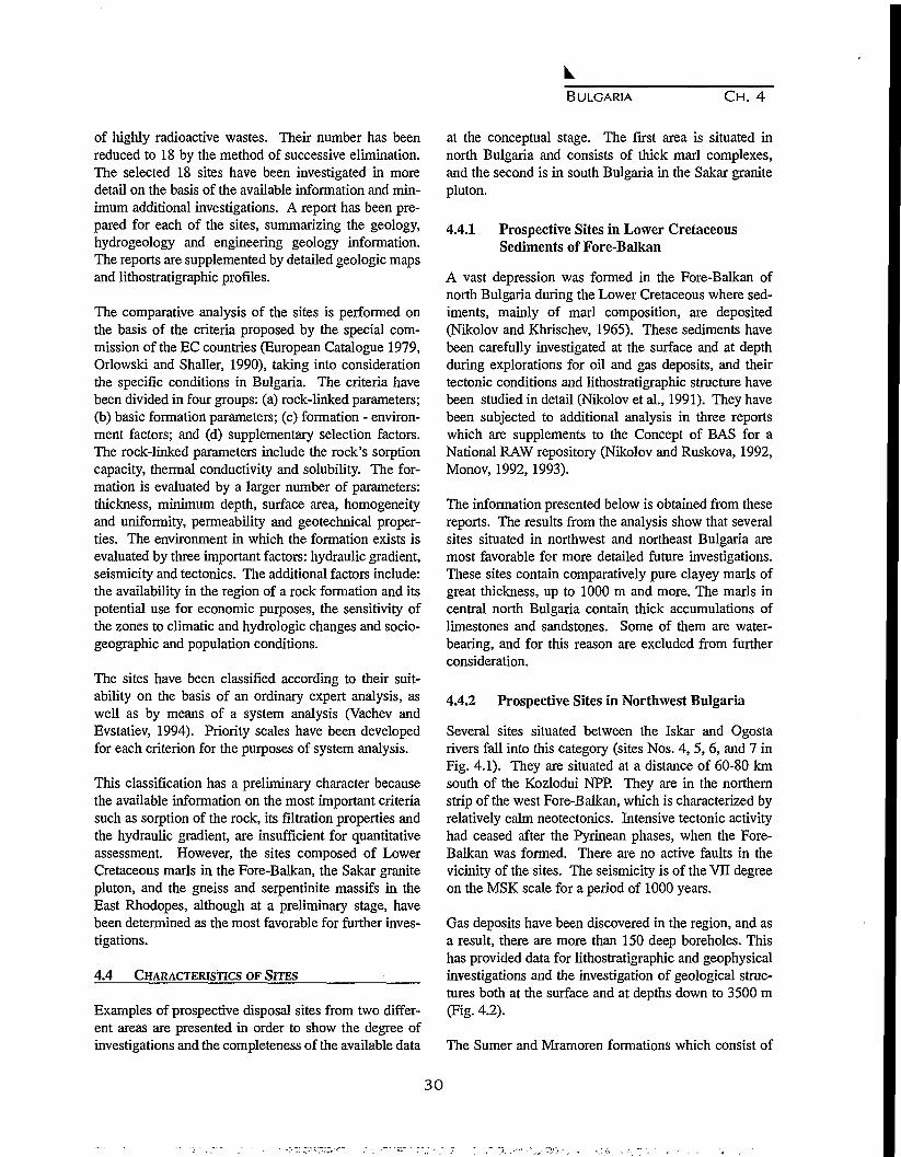
BULGARIA CH. 4
of highly radioactive wastes. Their number has beenreduced to 18 by the method of successive elimination.The selected 18 sites have been investigated in moredetail on the basis of the available information and min-imum additional investigations. A report has been pre-pared for each of the sites, summarizing the geology,hydrogeology and engineering geology information.The reports are supplemented by detailed geologic mapsand lithostratigraphic profiles.
The comparative analysis of the sites is performed onthe basis of the criteria proposed by the special com-mission of the EC countries (European Catalogue 1979,Orlowski and Shaller, 1990), taking into considerationthe specific conditions in Bulgaria. The criteria havebeen divided in four groups: (a) rock-linked parameters;(b) basic formation parameters; (c) formation - environ-ment factors; and (d) supplementary selection factors.The rock-linked parameters include the rock's sorptioncapacity, thermal conductivity and solubility. The for-mation is evaluated by a larger number of parameters:thickness, minimum depth, surface area, homogeneityand uniformity, permeability and geotechnical proper-ties. The environment in which the formation exists isevaluated by three important factors: hydraulic gradient,seismicity and tectonics. The additional factors include:the availability in the region of a rock formation and itspotential use for economic purposes, the sensitivity ofthe zones to climatic and hydrologic changes and socio-geographic and population conditions.
The sites have been classified according to their suit-ability on the basis of an ordinary expert analysis, aswell as by means of a system analysis (Vachev andEvstatiev, 1994). Priority scales have been developedfor each criterion for the purposes of system analysis.
This classification has a preliminary character becausethe available information on the most important criteriasuch as sorption of the rock, its filtration properties andthe hydraulic gradient, are insufficient for quantitativeassessment. However, the sites composed of LowerCretaceous marls in the Fore-Balkan, the Sakar granitepluton, and the gneiss and serpentinite massifs in theEast Rhodopes, although at a preliminary stage, havebeen determined as the most favorable for further inves-tigations.
4.4 CHARACTERISTICS OF SITES •
Examples of prospective disposal sites from two differ-ent areas are presented in order to show the degree ofinvestigations and the completeness of the available data
at the conceptual stage. The first area is situated innorth Bulgaria and consists of thick marl complexes,and the second is in south Bulgaria in the Sakar granitepluton.
4.4.1 Prospective Sites in Lower CretaceousSediments of Fore-Balkan
A vast depression was formed in the Fore-Balkan ofnorth Bulgaria during the Lower Cretaceous where sed-iments, mainly of marl composition, are deposited(Nikolov and Khrischev, 1965). These sediments havebeen carefully investigated at the surface and at depthduring explorations for oil and gas deposits, and theirtectonic conditions and lithostratigraphic structure havebeen studied in detail (Nikolov et al., 1991). They havebeen subjected to additional analysis in three reportswhich are supplements to the Concept of BAS for aNational RAW repository (Nikolov and Ruskova, 1992,Monov, 1992,1993).
The information presented below is obtained from thesereports. The results from the analysis show that severalsites situated in northwest and northeast Bulgaria aremost favorable for more detailed future investigations.These sites contain comparatively pure clayey marls ofgreat thickness, up to 1000 m and more. The marls incentral north Bulgaria contain thick accumulations oflimestones and sandstones. Some of them are water-bearing, and for this reason are excluded from furtherconsideration.
4.4.2 Prospective Sites in Northwest Bulgaria
Several sites situated between the Iskar and Ogostarivers fall into this category (sites Nos. 4, 5, 6, and 7 inFig. 4.1). They are situated at a distance of 60-80 kmsouth of the Kozlodui NPP. They are in the northernstrip of the west Fore-Balkan, which is characterized byrelatively calm neotectonics. Intensive tectonic activityhad ceased after the Pyrinean phases, when the Fore-Balkan was formed. There are no active faults in thevicinity of the sites. The seismicity is of the VII degreeon the MSK scale for a period of 1000 years.
Gas deposits have been discovered in the region, and asa result, there are more than 150 deep boreholes. Thishas provided data for lithostratigraphic and geophysicalinvestigations and the investigation of geological struc-tures both at the surface and at depths down to 3500 m(Fig. 4.2).
The Sumer and Mramoren formations which consist of
30
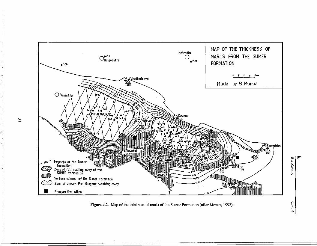
o;.P-16
Dulgodeltsi
Hairedin
o,P-15
Wladimirovo
MAP OF THE THICKNESS OFMARLS FROM THE SUMERFORMATION
Made by B. Monov
puhatche
Isopachs of the Sumerformation
Zone of full washing away of theSUMER formation
Surface outcrop of the Sumer formation1 Zone of uneven Pre-Neogene washing away
Prospective sites
CD
i
Figure 4.2. Map of the thickness of marls of the Sumer Formation (after Monov, 1993). n

BULGARIA CH. 4
very thick clayey marls are of greatest interest from thepoint of view of the construction of an in-depth reposi-tory (Fig. 4.3). The available hydrogeological data indi-cate that the marls are dry and of very low permeability.
4.4.3 Prospective Sites in Northeast Bulgaria
The Gorna Oryahovitsa formation, in the LowerCretaceous sediments of northeast Bulgaria, is mostinteresting as a prospective site for RAW disposal.(Nikolov et al., 1991). The formation consists of LowerCretaceous clayey marls where terrigenous intercala-tions are almost absent (Figs. 4.4 and 4.5). The select-ed site (No. 1 in Fig. 4.1) near the village of Zlatar,Shoumen district, is situated in a shallow anticline andis characterized by a low level of neotectonics and lackof active faults. The marl thickness exceeds 600 m. TheTicha formation, which is a buffer zone also containingthick marl layers, occurs in the Gorna Oryahovitsa for-mation (Fig. 4.5). The seismicity of the region is of VHIdegree on the MSK scale according to the seismic mapfor a period of 1000 years.
The Concept of BAS accepts marl terrains as possibili-ties for both in-depth disposal of high level RAW andthe surface-type repository for low- and medium-levelRAW. From the point of view of problems related withthe attitude of the population concerning the RAWrepository, it is advantageous to build repositories forboth types of waste at one and the same place.
Two types of repositories are proposed for considerationfor in-depth disposal of high level RAW: (1) mine dis-posal and (2) borehole disposal. The comparativelysmall volumes of this type of waste make it possible toconsider the construction of the second type of reposito-ry, which is less expensive and possesses certain tech-nological and ecological advantages. Moreover, consid-erable experience exists in Bulgaria on the performanceof deep boreholes, in marl rocks, in relation to the explo-ration for oil and gas deposits.
4.4.4 Prospective Sites in Magmatic-Metamorphic Terrains
Several sites with magmatic and highly metamorphicrocks in southeast Bulgaria are proposed in the Conceptof BAS. The following sites have been selected aftercomprehensive analysis of natural conditions in this partof the country: the Byala Reka structure, composed ofPrecambrian highly metamorphic gneisses; the Avren
and Zhalti Chal sites, composed of metaultrabasites; theSakar site, composed of Paleozoic granites and two sitesin the East Rhodopes Paleogene depression, composedof volcanic and volcanogenic sediments (Nos. 9,10,11,13, 14, 15 and 16 in Fig. 4.1). Preliminary explorationson these sites have been performed by Kozhoukharova(1992), Kozhoukharova and Kozhoukharov (1992), andKozhoukharova, et al. (1992).
4.4.5 Prospective Sites in Paleozoic Granites ofSakar Pluton
The Sakar site in southeast Bulgaria (No 13 in Fig. 4.1)is entirely within the area of the mountain of the samename. The region is composed of Precambrian high-crystalline metamorphites, Paleozoic metasedimentsand granites, Triassic metasediments and Pliocene for-mations (Kozhoukharov et al., 1994a, b). From a tecton-ic point of view, the region falls into the range of theSakar unit, which is a component of the Sakar-Strandzha tectonic zone. About 60% of the site is com-posed of Paleozoic granites, known as the Sakar pluton.At the surface, the granites have been well investigated,but there are no data about their condition at depth.There are no active faults in them from the neotectonicstage; faults of this type are observed along the periph-ery of the mountain beyond the limits of the pluton. Theseismicity is of the VTI degree on the MSK scale for aperiod of 1000 years.
4.4.6 Characteristics of Sakar Pluton
The Sakar pluton was emplaced entirely among the Pre-cambrian high-crystalline, ortho- and para-metamor-phites of the Prazhodopian supergroup (Kozhoukharov,1984, 1987) with presumed age of Archaic (?) - LowerProterozoic. It intrudes and is partially metamorphosedby contact with the porphyric blastic migmatites of thePanovo formation, the different gneisses, gneiss-schistsand schists, amphibolites, graphite- and iron-bearingquartzites, etc., of the Zhalti Chal variegated formationas well as the metaconglomerates of the Konstantinovoformation. A multitude of xenolites of these rocks occurin the peripheral parts of the pluton. At its western end,the Sakar pluton crosses and contact metamorphosesUpper Carboniferous sediments. The basic varieties ofthe granitoids in the Sakar batholith are three: uniform-ly grained; porphyric and porphyroid and aplitoid-peg-matoid (Alexandrovo) granites.
The porphyric granites are found in the western parts of
32
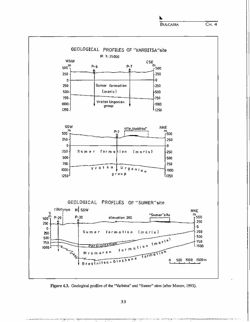
BULGARIA CH. 4
GEOLOGICAL PROFILES OF "VARBITSA"site
wr500*
250-
u *
250500-
750-
1000-
1250-
SSirr
500-
250-
fi-
250-
500-
750-
1000-
1250-
M 1:25000
m1 P-6 P-
+ t—t
• ,
Sumer formation
(marls)
Vratsa Urgoniangroup
NP-
H •—— -A
S u m e r f o r m a
-—.V
. — •
r a t s a
9 r
CSE7 r
site,.Varbitsa"-7 i 1
\ L .̂ . !
t i o n ( m a r l s )
l / r g
o u p
•0 n '• a „
n•500
•250
-250
-500
-750
•1000
•1250
NNrEn-500
-250A
-250
-500
-750
•1000
•1250
500 m P-29250-
0
250500-
750-1000-
GEOLOGICAL PROFILES OF "SUMER"site
r.Botunya N | SSW
elevation 300P-30"Sumer"s i te
S u m e r f o r m a t i o n ( m a r l s )
NNEmr500•250
•0-250•500-750•1000
t B r e s t m0 500 1000 1500m
Figure 4.3. Geological profiles of the "Varbitsa" and "Sumer" sites (after Monov, 1993).
33
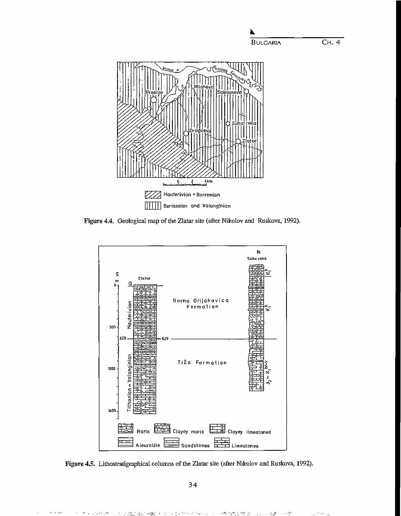
BULGARIA CH. 4
3?m
'<m22
Y//A Hauterivian + Barremian
|| 11 111 Beriassian and Valanginian
Figure 4.4. Geological map of the Zlatar site (after Nikolov and Ruskova, 1992).
NSuha reka
Zlatar
500-
1000-
1500.
629-
' -- » — '
T f T
Gorna O r i j a h o v i c aF o r m a t i o n
-629
T i c a Fo r m a t i o n
Marls I ' "~ ' I Clayey marls
Aleurolite Sandstongs
^3 Clayey limestones
Limestones
Figure 4.5. Lithostratigraphical columns of the Zlatar site (after Nikolov and Ruskova, 1992).
3 4

BULGARIA CH. 4
Figure 4.6. Geological map of the Sakar pluton: 1 - Quaternary; 2 - Pliocene sediments; 3 - Upper Paleozoic andTriassic metasediments; 4 - leucocratic (Alexandrovo) granites, Sakar pluton; 5 - medium-grained gran-ites; 6 - porphyric granites, Precambrian; 7 - Lessovo gneiss-granites; 8 - metaultrabasites; 9 - ZhaltiChal variegated formation; 10 - Konstantinovo metaconglomerate formation; 11 - Panovo porphyric-blastic formation; 12 - faults; 13 - a site, suitable for high level RAW disposal (after Kozhoukharov,1992).
the pluton. The porphyries are of potassium feldsparand are characterized by a great variety of sizes and rocksaturations. Their length usually varies from severalcentimeters to 7-8 cm, sometimes reaching 12-15 cm.The porphyric granites are biotitic to two-mica ones.The uniformly grained granites are medium to coarsegrained. They elevate the region between the villages ofGlavan, Balgarska Polyana, Hlyabovo, Sakartsi and theneighbourhood of the Bairaka and Karaburun peaks.The micas are of the biotite type, but two-mica varietiesalso occur.
The mineral composition of the two facial varieties isanalogous. They are composed of: quartz, plagioclase,microcline, biotite and occasionally of muscovite andaccessory minerals - apatite, zircon, garnet, sphene andclinozoisite. Biotite is often replaced by muscovite andsome microclines exhibit later crystallization and activeerosion of the plagioclases.
The Alexandrovo leucocratic, aplitoid-pegmatitic gran-ites have a wider distribution than that shown on themap sheet. They occur in the form of elongated bodies
and veins mainly in the east-west direction in the south-ern parts of the pluton, where they cross the rocks of thePanovo and Zhalti Chal formation and the two facialvarieties of the Sakar batholith.
The granites are fine- and medium-grained and occa-sionally coarse-grained. Three varieties are distin-guished among them: medium-grained muscovite gran-ites, coarse-grained pegmatoid granites and fine-grainedaplitoid granites. The individual varieties are trans-formed into each other, but the dominating granites aremedium grained, while the aplitoid ones mainly occupythe peripheral parts of the rock bodies or fill some of theveins. These granites do not differ in their mineral com-position from the other two varieties of the Sakarbatholith except for the biotite content, which is quiterare or missing in the Alexandrovo granites.
Different opinions have formed concerning the age ofthe Alexandrovo and Sakar granites, covering the rangefrom the Archaic (?) to the Jurassic. The direct geolog-ical relationships between the Alexandrovo and Sakargranites, which intrude and contact metamorphose the
35

BULGARIA CH. 4
rocks of the Paleozoic Klokotnitsa Formation, as well asoutliers of granite in the Lower Triassic metasediments(Sakar type) provide the basis for assuming that theirage is Upper Paleozoic.
Three categories of terrains are distinguished in theSakar pluton according to its internal structure. The site,composed of medium-grained granites, indicated by aspecial symbol on the geological map (Fig. 4.6) is con-sidered to be the most suitable for further investigationand construction of a RAW repository.
REFERENCES
Boncev, E., Problemi na balgarskata geotektonika(Problems of Bulgarian Geotectonics), Sofia,Technika, 203 pp., 1971. (in Bulgarian)
Commission of the European Communities, Europeancatalogue of geological formations having favourablesolidified characteristics for the disposal of high-level and/or long-lived radioactive wastes,Introduction and summary. Volume compiled byBRGM, France, 79 p.,1979.
Evstatiev, D., and B. Vachev, Site selection procedurefor high level radioactive waste disposal in Bulgaria,IAEA regional project for Technical AssistancePEP/9/010, Recommendations on management ofradioactive wastes WER, Meeting in Sofia, 1993.
Geological map of Bulgaria on scale 1:100,000, 96sheets.
Iliev, I., ed., Map of the Geological Hazards in Bulgaria,Committee of Geology, Bulgarian Academy ofSciences, Sofia, 1994.
Kostadinov, V. and D. Kozhoukharov, Categorization ofterrains on Bulgarian territory, In: Concept of BASfor a national RAW repository, 1992.
Kozhoukharov, D., Lithostratigraphy of Precambrianmetamorphics from Rhodope Supergroup in theCentral Rhodopes, Geologica Bale, 14, 1, 43-88,1984.
Kozhoukharov, D., Lithostratigraphy and structure ofthe Precambrian metamorphics from the core ofBiala-reka Dome, East Rhodope Mts., GeologicaBale, 17, 2,15-38,1987.
Kozhoukharov, D., Composition, structure and complexgeological assessment of the Biala-Reka structure inthe East Rhodopes, In: Concept of BAS for NationalRAW repository, 1992.
Kozhoukharova, E., and D. Kozhoukharov, Petrographiccharacteristics and complex geological assessment ofthe ultrabasite bodies in the region of the Zhalti Chalvillage, Ivailovgrad district, In: Concept of BAS forNational RAW repository, 1992.
Kozhoukharova, E., D. Kozhoukharov, S. Pristavova,and M. Ichev, Geological structure and complex geo-logical assessment of the Sakar site, In: Concept ofBAS for National RAW repository, 1992.
Kozhoukharov, D., S. Savov, G. Catalov, E. Kozhou-kharova, A. Goranov, and I. Bojanov, Geologicalmap of Bulgaria on scale 1:100,000, sheetTopolovgrad, 1994a.
Kozhoukharov, D., I. Bojanov, E. Kouzhoukharova, andA. Goranov, Geological map of Bulgaria on scale1:100,000, sheet Svilengrad, 1994b.
Monov, B., Lithostratigraphy of the Lower Cretaceousin Northwest Bulgaria (the Lorn depression and theWest Fore-Balkan), In: Concept of BAS for aNational RAW repository, 1992.
Monov, B., Prospective sites for investigations concern-ing the construction of a surface-type repository forlow and medium active RAW in the LowerCretaceous marls in Northwest Bulgaria, In:Concept of RAS for a National RAW repository,1993.
Milanov, M., D. Evstatiev, and D. Kozhoukharov,Concept for National Repository for RadioactiveWastes in Republic of Bulgaria (Summary),Bulgarian Academy of Sciences, 40 pp, 1993.
Nikolov, T. and K. Khrischev. Osnovi na stratigrafiata ilitologiata na dolnata kreda v Predbalkana(Principles of the stratigraphy and lithology of theLower Cretaceous in the Fore-Balkan), Geology ofBulgaria, Series: Stratigraphy and Tectonics, 6, 77-175,1965. (in Bulgarian)
Nikolov, T., and N. Ruskova, Geological structure and acomplex geological assessment of the LowerCretaceous in the Fore-Balkan between the rivers of
36
BULGARIA CH. 4
Ossam and Louda Kamchia with suggestions for thelocation of RAW repository, In: Concept of BAS fora National RAW repository, 1992.
Nikolov, T., N. Ruskova and K. Khrischev, Osnovilitostratigrafii nizhnemelovogo otdela v Bolgarii(Principles of the Lower Cretaceous lithostratigraphyin Bulgaria), Geologica Bale, 21, 6, 3-47,1991. (inBulgarian)
Orlowski, S. and V. H. Shaller, Objectives, standardsand criteria for radioactive waste disposal in theEuropean Community, Euradwaste series No 1,81pp., 1990.
Vachev, B., and D. Evstatiev, Radioactive wastes man-agement: Application of AHP, Proc. of the ThirdInternational Symposium of the Analytic HierarchyProcess, Session W2A, George WashingtonUniversity, Washington D.C., July, 11-13,1994.
37

38

CHAPTER 5
CANADA'S NUCLEAR FUEL WASTE MANAGEMENT PROGRAM:
THE ENVIRONMENTAL ASSESSMENT OF THE DISPOSAL CONCEPT
C.J. Allan and C.R. Simmons
Atomic Energy of Canada Limited, Whiteshell Laboratories,Pinawa, Manitoba ROE 1 LO, Canada
Abstract. Over the last 17 years under the Nuclear Fuel Waste Management Program, Atomic Energy of CanadaLimited (AECL) has developed and assessed a concept to dispose of nuclear fuel waste from Canada's CANDU reac-tors in a vault excavated in plutonic rock of the Canadian Shield. A robust concept has been developed, with optionsfor the choice of materials and designs for the different engineered components of the disposal system. AECL sub-mitted in 1994 October an Environmental Impact Statement on the Concept for the Disposal of Canada's NuclearFuel Waste for review under the Canadian Environmental Assessment and Review Process. If the review is complet-ed in 1996, as currently expected, and if the concept is accepted by the review panel and approved by government,disposal would not likely begin before about 2025.
5.1 INTRODUCTION
About 20% of Canada's electricity is generated usingCANDU nuclear reactors. Three provincial utilities,Ontario Hydro, Hydro-Quebec and New BrunswickPower, own these reactors and the used fuel removedfrom them. The used fuel is currently stored in water-filled pools or in dry-storage concrete storage structures.Current storage practices, while safe, require continuinginstitutional controls, such as security measures, moni-toring and maintenance. Thus, storage is an effectiveinterim measure for the protection of human health andthe environment, but not a permanent measure. Disposalis needed to manage nuclear fuel waste in a way thatdoes not depend on institutional controls to maintainsafety in the long term.
Canada, like other countries, is basing its plans for dis-posal of nuclear fuel waste on deep geological disposalin the rock of a continental land mass. The Nuclear FuelWaste Management Program (NFWMP) was launchedin 1978 as a joint initiative by the governments ofCanada and Ontario. Under the program, AtomicEnergy of Canada Limited (AECL) has been developingand assessing a concept to dispose of nuclear fuel wastein plutonic rock of the Canadian Shield. Ontario Hydrohas advanced the technologies for interim storage andtransportation of used fuel. The two governments statedin 1981 that selection of a nuclear fuel waste disposalsite would not proceed until the concept had been
reviewed and assessed. Thus, a generic rather than asite-specific concept has been developed.
Participants in the program have included AECL, thelead agency for research on nuclear fuel waste disposal;Ontario Hydro, which has advanced the technologies forstorage and transportation as well as contributing finan-cially and technically to the R&D on disposal; NaturalResources Canada (NRCan); Environment Canada; sci-entists at Canadian universities; and consultants in theprivate sector. An independent Technical AdvisoryCommittee has provided advice on the scope and quali-ty of the technical work.
During the past seventeen years, AECL has carried outdetailed studies on the multiple-barrier disposal con-cept. The objective has been to develop a concept withflexibility in the choice of methods, materials, anddesigns for the components of the disposal system. Theapproach has focused on ensuring that the system as awhole meets safety standards by a large margin.
5.2 THE DISPOSAL CONCEPT
The disposal concept being investigated is a proposedmethod for the geological disposal of nuclear fuel wastein which:
1. The waste form would either be used CANDU fuel orsolidified highly radioactive reprocessing waste;
3 9

CANADA CH. 5
2. The waste form would be sealed in a containerdesigned to last at least 500 years and possibly muchlonger;
3. The containers of waste would be placed in rooms ina disposal vault or in boreholes drilled from therooms;
4. The vault would be nominally 500 to 1000 metresdeep;
5. The geological medium would be plutonic rock ofthe Canadian Shield;
6. Each waste container would be surrounded by abuffer;
7. Each room would be sealed with backfill and othervault seals; and
8. All tunnels, shafts and exploration boreholes wouldultimately be sealed so that the disposal facilitywould be passively safe, that is, so that long-termsafety would not depend on institutional controls.
After the disposal vault is closed, a series of engineeredand natural barriers would protect humans and the nat-ural environment from the radioactive and chemicallytoxic contaminants in the nuclear fuel waste. These bar-riers include the waste form; the container; the buffer,backfill and other vault seals; and the geosphere (therock, any sediments overlying the rock below the watertable and the groundwater flow system). Institutionalcontrols would not be required to maintain safety in thelong term.
The nuclear fuel waste, or waste form, would be eitherused CANDU fuel or, if the used fuel was reprocessedin the future, the solidified highly radioactive wastefrom reprocessing. The low solubility of used CANDUfuel under the expected disposal conditions would makeit effective for retaining radioactive and chemicallytoxic contaminants, thus it is an excellent waste form inits current state. The liquid radioactive waste that wouldresult if used fuel were reprocessed would not be suit-able for direct disposal, but such waste could be solidi-fied to produce an excellent waste form.
The waste form would be sealed in a container to facil-itate handling and to isolate it from groundwater for adesired minimum time. The container would bedesigned to have a minimum life of 500 years followingemplacement in a disposal vault. As the conditions atpotential sites may vary, the container geometry, mater-ial and fabrication method would be developed for eachparticular waste form and site. Important considerationsin the design of containers would include the tempera-ture and pressure that would be imposed on the contain-
er at the depth and location selected for the disposalvault and the chemical and microbial environmentexpected at each site.
The containers of nuclear fuel waste would be emplacedin a disposal vault excavated nominally 500 to 1000metres below the surface in the plutonic rock of theCanadian Shield. The disposal vault would be a networkof horizontal tunnels and disposal rooms that would beexcavated deep in the rock, with vertical shafts extend-ing from the surface to the tunnels. Rooms and tunnelsmight be excavated at more that one level. The vaultwould be designed to accommodate the rock structureand the subsurface conditions at the chosen site. Themethod of emplacing the containers in the vault wouldbe selected to suit the specific characteristics of the siteand container geometry. Figure 5.1 shows two possibil-ities for emplacing waste in a vault.
Within the multiple barrier system, the vault seals wouldperform the following functions to enhance the isolationof the nuclear fuel waste:
1 . The buffer would inhibit the movement and modifythe chemistry of the groundwater near each contain-er to limit the container corrosion rate, the wasteform dissolution rate, and the movement of contami-nants;
2. The backfill would fill the space in disposal rooms tokeep the buffer and containers securely in place, andin shafts and tunnels to reduce the potential forhuman intrusion. It would also retard the movementof contaminants by slowing the movement ofgroundwater, enhancing sorption of contaminantsand by chemically conditioning the groundwater;
3. Bulkheads would inhibit groundwater movement atthe entrance of disposal rooms, contain any pressuresexerted by the backfill, and prevent easy humanaccess to the emplaced waste;
4. Plugs and grouts, located at hydraulically criticallocations in the disposal vault, such as locationswhere shafts and tunnels intersect fracture zones,would inhibit groundwater movement and the poten-tial for contaminant transport in the excavations andin the rock around excavations; and
5. Shaft seals would prevent the shafts from being apreferential pathway for groundwater movement andwould reduce the possibility of human intrusion intothe sealed disposal vault.
The materials selected for vault seals need to have lowhydraulic conductivity (in the order of 10'10 m/s or
40

CANADA C H . 5
In-Borehole Emplacement
Container
Backfill Buffer
In-Room Emplacement
500-1000 m
Figure 5.1. The disposal concept showing two examples of waste emplacement.
lower), must be available in the volumes required, mustbe workable and placeable with current technology, andmust have predictable long-term performance.
The geosphere, comprising the plutonic rock, any sedi-ments overlying the rock below the water table, and thegroundwater flow system, would surround the disposalvault. The function of the geosphere, as a barrier, wouldbe to protect the waste form, the container and the vaultseals from natural disruptions and human intrusion; tomaintain conditions in the vault favourable for long-term waste isolation; and to limit the rate at which con-taminants from the waste could move from the vault tothe biosphere. Any characteristics of a geological medi-um that support or enhance these functions would beconsidered favourable.
The plutonic rock bodies of the Canadian Shield areconsidered favourable as a disposal medium for Canada
because they have many characteristics consideredfavourable including:
1. Wide geological distribution, allowing flexibility insiting, and wide distribution in regions of low topo-graphic relief, where the driving force for groundwa-ter movement in the rock is likely to be low;
2. Geological stability and the likelihood of remainingstable;
3. Very large size, in many cases, allowing the disposalrooms to be located away from discontinuities;
4. Fewer ore bodies associated with them than othertypes of rock bodies;
5. Relatively high thermal conductivity to dissipate theheat released from the emplaced waste;
6. Chemical composition and hydrogeological charac-teristics that favour retention and retardation of thetype of contaminants expected in the waste form; and
7. Low frequency of permeable fractures, away from
41
CANADA C H . 5
the widely spaced fracture zones, below a depth of200 to 500 metres.
The choice of methods, materials, and designs for anactual disposal system will ultimately be made on thebasis of performance assessments taking into accountthe characteristics of the specific site on which the facil-ity is to be developed, availability of materials, cost, andpracticality. They could include, for example:
• the form of the waste: used fuel bundles or fuel repro-cessing waste incorporated in a stable matrix, e.g.glass or ceramic;
• the disposal container material: titanium alloy, cop-per, or other durable material;
• the container design;• the composition of materials used for the buffer,
backfill, and other seals;• the excavation method: blasting or boring;• the depth, geometry, and the number of levels of the
vault;• the size and shape of the excavated openings; and• the location of the waste containers: within disposal
rooms or in boreholes drilled from the rooms.
These choices will not be made until a site for a vaulthas been selected.
5.3 ENVIRONMENTAL REVIEW
The federal Department of Energy, Mines andResources (EMR) (now Natural Resources Canada,NRCan) referred the concept for review under theEnvironmental Assessment and Review Process (EARP)in 1988. As the "Proponent" for this review, AECL isresponsible for preparing and submitting anEnvironmental Impact Statement (EIS) describing theconcept. The Environmental Assessment Panel responsi-ble for carrying out the review is chaired by Mr. BlairSeaborn. The Panel has appointed a Scientific ReviewGroup (SRG), chaired by Professor Raymond Price andcomposed of eminent scientists from a variety of rele-vant disciplines, to assist it in judging the technicalvalidity and acceptability of the disposal concept. TheCanadian Environmental Assessment Agency (CEAA),formerly Federal Environmental Assessment ReviewOffice (FEARO), provides administrative support to thePanel.
The Panel will review AECL's concept, along with abroad range of nuclear fuel waste management issues.These include the criteria for determining safety and
acceptability; the approaches used in handling nuclearfuel waste both in Canada and other countries; thepotential social, economic, and environmental effects ofwaste disposal; and the potential impact of recycling andother processes on waste volume. A general review ofother aspects of the nuclear industry, such as energy pol-icy and reactor operation and safety, is specificallyexcluded from the Panel's review.
All federal departments with a relevant interest in theconcept are expected to participate in the reviewprocess. These include the Atomic Energy ControlBoard (AECB), NRCan, Environment Canada, Healthand Welfare Canada, and Transport Canada. NRCan hasassembled a team to review the results of AECL's R&Dprogram, and Environment Canada has assembled twoteams of experts to review in detail how well the conceptprotects the environment.
When the EARP review is concluded, the Panel willmake recommendations as to the acceptability of theconcept and the course of future action regardingnuclear fuel waste disposal. Government decisions willthen follow.
In the spring of 1990, CEAA organized a series of"Open Houses" to inform interested parties, not directlyconnected with the nuclear industry or with the scientif-ic review process, about how they could take part in thereview. "Scoping Hearings" took place in the autumn of1990 to identify issues of concern, and to assist thePanel in setting guidelines for the EIS. One hundred andthirty participants made presentations, including gov-ernment departments, scientific and business organiza-tions, special interest groups, and private individuals.Among the major issues raised were arguments for andagainst storage as compared with disposal, the adequa-cy of the regulatory criteria, and monitoring the perfor-mance of the disposal vault. Aboriginal land claimsaffect much of the land where a disposal vault could besited. In view of this, an aboriginal representative wasadded to the Panel.
In June 1991 the Panel issued draft EnvironmentalImpact Statement guidelines for comment. Over thirtydifferent groups and individuals submitted comments.The Panel issued its final guidelines to AECL in Marchof 1992.
AECL responded to these guidelines by preparing andissuing the Environmental Impact Statement and nineprimary reference documents to support the
42

CANADA C H . 5
Environmental Impact Statement. These documents pro-vide a complete description of the concept and the tech-nology that has been developed over the past 15 years.The EIS also provides additional information specifical-ly requested by the Panel.
The nine primary references were issued in 1993 and1994. The Environmental Impact Statement on theConcept for Disposal of Canada's Nuclear Fuel Waste,and the Summary of the Environmental ImpactStatement on the Concept for Disposal of Canada'sNuclear Fuel Waste were completed and submitted tothe EARP Panel in 1994 October. The Panel releasedthese documents to the public and initiated a nine monthreview period for the public to assess their completenessand provide comments to the Panel. By 1995 January31, AECL had distributed about 18,500 copies of thesedocuments.
From 1994 November to 1995 March, CEAA conduct-ed another series of Open Houses in 21 communitiesacross the review provinces; New Brunswick, Quebec,Ontario, Manitoba and Saskatchewan. These weredesigned to familiarize the public with the reviewprocess, the disposal concept, and nuclear fuel wastetransportation and storage and to encourage their partic-ipation in the review of the completeness of the EIS andin the Public Hearings announced for later. At many ofthe Open Houses, short formal presentations were madeby CEAA, AECL and Ontario Hydro staff. These wereoften followed by a question period. About 2750 peopleattended the presentations or visited the AECL exhibit.
The environmental assessment panel released itsapproach for the public hearings in 1994 August. Theapproach is divided into three phases:
1. Phase I is designed to assist the panel addressingissues in the panel's terms of reference which gobeyond the generic concept for deep geologic dispos-al including: the criteria by which safety and accepti-bility of a concept for long-term management anddisposal should be evaluated; the degree to which thisgeneration should relieve future generations of theburden of caring for the waste; social, economic andenvironmental implications of a possible nuclear fuelwaste management facility; the general criteria forsite selection and a future site selection process; andthe potential costs and benefits to potential host com-munities. This phase is scheduled for 1996 Marchand April in Toronto and other communities inOntario.
2. Phase II of hearings will focus specifically on scien-tific and technical issues related to the safety of theAECL's generic concept for deep geologic disposalof nuclear fuel waste. This phase is scheduled for1996 June in Toronto.
3. Phase HJ hearings will be held over six weeks in theautumn of 1996 in a number of communities in fiveprovinces previously visited by the panel during thescoping phase of this review. This phase will involvepresentations on: recommendations to assist govern-ments in reaching decisions on the acceptability ofthe disposal concept; steps to be taken to ensure safelong-term management of nuclear fuel waste; criteriaby which the safety and acceptability of a concept forlong-term waste management and disposal should beevaluated; social, economic and environmentalimplications of a possible nuclear fuel waste man-agement facility, including the impact of trans-portaion of nuclear fuel waste; general criteria forsite selection and on a future site selection process;and the costs and benefits to potential host communi-ties.
5.4 THE ENVIRONMENTAL IMPACT STATEMENT AND
PRIMARY REFERENCES
The Environmental Impact Statement document pro-vides an overview of AECL's case for the acceptabilityof the disposal concept, and provides information aboutthe following topics:
• the characteristics of nuclear fuel waste;• storage and the rationale for disposal;• major issues in nuclear fuel waste management;• the disposal concept and implementation activities;• alternatives to the disposal concept;• methods and results of the environmental assess-
ments;• principles and potential measures for managing envi-
ronmental effects; and• AECL's overall evaluation of the disposal concept.
The nine Primary References expand on particularsocioeconomic and technical aspects AECL has evaluat-ed in developing the concept:
Public Involvement and Social Aspects
• describes the activities undertaken to provide infor-mation to the public about the program and to obtainpublic input into the development of the disposal
43

CANADA CH. 5
concept;presents the issues raised by the public and how theissues have been addressed during the developmentof the disposal concept or how they could beaddressed during the implementation of the disposalconcept; anddiscusses social aspects of public perspectives onrisk, ethical issues associated with nuclear fuel wastemanagement, and principles for the development of apublicly acceptable site selection process.
socioeconomic environment that could be associatedwith siting, constructing, operating (including trans-porting used fuel), decommissioning, and closing adisposal facility;describes an application of this assessment method-ology to a reference disposal system;discusses technical and social factors that would needto be considered during siting; anddiscusses possible measures and approaches for man-aging environmental effects.
Site Screening and Site Evaluation Technology
• discusses geoscience, environmental, and engineer-ing factors that would need to be considered during asiting process; and
• describes the methodology for site characterization,that is, for obtaining the data about regions, areas,and sites that would be needed for facility design,monitoring, and environmental assessment.
Engineered Barriers Alternatives
• describes the characteristics of nuclear fuel waste;• describes the materials that were evaluated for use in
engineered barriers, such as containers and vaultseals;
• describes potential designs for containers and vaultseals; and
• describes procedures and processes that could beused in the production of containers and the emplace-ment of vault-sealing material.
Engineering for a Disposal Facility
• discusses alternative vault designs and general con-siderations for engineering a nuclear fuel waste dis-posal facility; >
• describes a reference disposal facility design that wasused to assess the technical feasibility, costs, andpotential effects of disposal (The term "reference" isused to designate the disposal systems, including thefacility designs, specified for the assessment studies.Different disposal facility designs are possible andmight be favoured during concept implementation.);and
• presents cost and labour estimates for implementingthe reference design.
Preclosure Assessment of a Conceptual System
• describes a methodology for estimating effects onhuman health, the natural environment, and the
Postclosure Assessment of a Reference System
• describes a methodology for:- estimating the long-term effects of a disposal facil-ity on human health and the natural environment,- determining how sensitive the estimated effects areto variations in site characteristics, design parame-ters, and other factors, and- evaluating design constraints; and
• describes an application of this assessmentmethodology to a reference disposal system.
The Vault Model for Postclosure Assessment
• describes the assumptions, data, and models used inthe postclosure assessment to analyze processeswithin and near the buried containers of waste; and
• discusses the reliability of the data and models.
The Geosphere Model for Postclosure Assessment
• describes the assumptions, data, and models used inthe postclosure assessment to analyze processeswithin the rock in which a disposal vault is excavat-ed; and
• discusses the reliability of the data and models.
The Biosphere Model, BIOTRAC, for PostclosureAssessment
• describes the assumptions, data, and models used inthe postclosure assessment to analyze processes inthe near-surface and surface environment; and
• discusses the reliability of the data and models.
The EIS and the nine Primary References comprisesome 6000 pages.
5.5 REASONS FOR CONFIDENCE IN THE DISPOSAL
CONCEPT
Our confidence in the long-term safety of the concept
44
CANADA C H . 5
draws strength from a number of sources:
1. The technical approach, the use of multiple barriersfor redundancy and defence in depth;
2. The adoption of an observational approach to sitecharacterization and to disposal vault design, con-struction, operation and eventually closure;
3. An approach to the project which is based on ongo-ing review and decision-making and which recog-nizes that, throughout, the process must be flexibleand responsive and that decisions can be modified;and
4. Active and effective involvement of the public in theprocess.
5.6 THE MULTIBARRIER SYSTEM
In common with the approach adopted in other coun-tries, the concept developed by AECL involves isolatingthe waste from the biosphere by a series of engineeredand natural barriers. AECL's approach to developmentof the disposal concept has been to consider the perfor-mance of the system as a whole, rather than focusing onperformance requirements for individual components.This approach allows flexibility in implementation to beretained and it increases the likelihood of identifyingany counterintuitive interactions or synergisms amongsystem components that could adversely affect safety.Thus, the performance of individual components, suchas waste containers, is analyzed in the context of the sys-tem. This contrasts with a design and safety approachthat prescribes performance standards for individualcomponents and evaluates safety by the analysis of theperformance of each component independently. Ourgoal, therefore, has been to develop a thorough scientif-ic understanding of the performance of the differentcomponents of a disposal system and how these compo-nents interact and influence one another, so that theoverall system can be designed to provide defence indepth.
Acquiring and building the necessary knowledge base isa continuing process, and in implementing disposal,flexibility must be retained so that new information andunderstanding acquired over time can be integrated intothe disposal system. An example is container life-time.The original target was to achieve a minimum containerlife-time of 500 years and early work established thatthis goal could be achieved with a thin-walled titaniumcontainer. Subsequent studies on the corrosion of titani-um and copper indicated that, for the expected ground-water chemistry, thin-walled titanium containers can bedesigned to have a corrosion lifetime in excess of tens of
thousands of years, and a 25 mm thick copper containercan potentially provide containment in excess of 106
years. Such advances in understanding and in our abili-ty to defend, scientifically, this understanding can havea profound impact on the approach taken to facilitydesign and implementation, and on decision-making.
Much of the evidence needed to evaluate any site thatwould be considered for deep geological disposal can beobtained from geologic information developed as thesite is characterized, i.e., from the record of past changespreserved in the native rock mass and the groundwater.In the Canadian Shield the record available for investi-gation can be as long as two billion years.
Investigations at our field research areas, for example,indicate that discrete zones of intensely fractured rock,intersecting otherwise sparsely fractured rock, are thedominant pathways for groundwater flow at depthsgreater than 300 m to 500 m in plutonic rock of theCanadian Shield. The flux of groundwater can be highin the fracture zones; however, the flux is very low in thesparsely fractured rock bounded by the fracture zones,due to its very low permeability, which is commonlyless than 10~18 m2. Such low permeabilities can limit therate of contaminant movement and indicate that withinthe overall disposal system, the host rock can play animportant role as a natural barrier to the transport ofradionuclides.
The field evidence is supplemented and complementedby understanding derived from laboratory studies, Fieldstudies, including studies of natural analogues, canextend the short-term evidence from the laboratory stud-ies to the longer times of interest - tens and even hun-dreds of thousands of years - and provide verification ofthe understanding incorporated in predictive modeling.For example, studies of the Cigar Lake uranium depositin northern Saskatchewan have been under way since1984. The uranium ore in the deposit has essentially thesame composition as used fuel. It was formed some 1.3billion years ago and has been in contact with ground-water since its deposition. Yet the uranium has remainedstable under the reducing conditions prevailing in thedeposit. Similar conditions are expected to occur in adisposal vault.
5.7 THE OBSERVATIONAL METHOD
No organization in Canada has yet been given the man-date to proceed with siting a disposal facility.Nevertheless, we can anticipate that the approach thatwill be used in site characterization and disposal vault
45

CANADA C H . 5
Figure 5.2. Underground research laboratory.
design, construction, operation, and eventually closurewill be based on the observational method - theapproach used in good geotechnical engineering. Theobservational method is a systematized approach todealing with practical problems encountered when engi-neering in the sub-surface. In this approach, the resultsof modeling and computations during design are viewedas working hypotheses subject to confirmation or modi-fication during construction. This approach provides aframework for decision-making in a situation where it isnot practical, even if it were possible, to obtain all thedetailed geotechnical information that would be neededfor design of an underground facility prior to excavationat the site. As the project proceeds, the information iscontinuously acquired and incorporated into the design.A lack of detailed knowledge about local variabilitywithin a selected rock mass prior to excavation is com-mon in underground construction. Nevertheless, majorprojects such as underground powerhouses and storage
chambers, transportation tunnels, and dams are com-pleted successfully using a design approach that accom-modates observations made as construction is advanced.As part of its research program, AECL has constructedan Underground Research Laboratory for large-scaletesting and in-situ engineering experiments on aspectsof disposal (Figure 5.2). The observational method wasused during the design and construction of this facility.
The observational method is also central to the use ofperformance assessment analyses as part of the designand implementation process. It is a continuouslyapplied, iterative process. Beginning during the siteselection phase, assessments are made based on allavailable data on the site conditions. The understandingof the site is incorporated into models for use in designand in performance assessment studies. Both the designsand the assessments become more refined as the knowl-edge of a site increases. Design and operational deci-
46

CANADA CH. 5
sions are made on the basis of the understanding of siteconditions at the time. The maximum possible flexibili-ty is retained to incorporate technological improve-ments. In addition, the potential impacts of conceivabledeviations from site conditions as understood need to beassessed and contingency measures established, inadvance, to address the deviations should they beencountered.
As work proceeds, observation and evaluation of theactual conditions encountered are compared with theprevious understanding and, if necessary, the detaileddesign and the models used in performance assessmentare modified. This cycle continues throughout site selec-tion, construction and operation, so that at each pointwhen significant licensing and operational decisionsneed to be made, a long record of observation and aseries of increasingly refined performance assessmentsare available on which to base the decision.
5.8 ONGOING REVIEW AND DECISION-MAKING
AECL views the current review as the beginning of acontinuing process. As the technology for managing thedisposal of nuclear fuel waste is developed and appliedto specific sites, further reviews and public consultationand involvement will be needed. Any facility will besubject to rigorous regulatory criteria, and it is antici-pated that society will demand that a step-by-stepprocess be followed. Thus, a decision to proceed on thebasis of the current review would represent only the firstof a series of decisions between distinct phases of theprocess.
Each phase should lead to increased confidence in theoverall system, thus facilitating decision-making abouthow and whether to proceed to the next phase. We arecurrently nearing the end of the first phase - conceptdevelopment and assessment. If the Panel sharesAECL's view that we have adequately developed theconcept, and there is a governmental decision to pro-ceed, the next appropriate step would be the start of site-specific activities, beginning with site screening. Thesequence of events could be as follows:
1. Site screening would lead to the selection of one ormore sites for detailed characterization based on sur-face techniques;
2. Such site characterization studies could lead to aselection of one or more sites for exploratory excava-tion and more extensive in-ground characterization;
3. In-ground characterization could lead to a decision toinitiate construction and operation of a disposal
vault, possibly beginning with a demonstrationphase;
4. Design, construction and operation of a facilitywould involve ongoing review, reassessment andrecommitment, leading to continued operation andthen eventually to a decision to cease operations anddecommission; and
5. Decommissioning and post-operational monitoringwould ultimately lead to a decision to close and sealthe vault.
The process of site screening and of evaluating severalsites will likely involve a further ten to fifteen years ofwork before a commitment would be made to initiate anunderground excavation, followed by a further ten yearsor so of site exploration and characterization before con-struction could begin. Thus, waste would not beemplaced in a vault before about 2025. By then wewould have accumulated many years of site-specificdata and a series of increasingly refined evaluations onwhich to base a decision to begin to emplace waste.
The decision to close and seal the vault would be madeon the basis of the accumulated evidence and experiencegained throughout the siting, characterization and oper-ational phases, a process extending over close to a cen-tury. Only with that decision will disposal based on theconcept have definitively been judged as safe andacceptable.
Thus, at the current concept assessment phase of theprocess, "concept approval" represents a judgment that:
• sufficient understanding has been developed to con-tinue with the process, with an expectation that wewill eventually reach the end point of sealing a vault;and that
• at the appropriate time, we should proceed to the nextphase of the program, the beginning of site-specificactivities to resolve outstanding issues that can onlybe resolved on a site-specific basis.
5.9 PUBLIC INVOLVEMENT
The general public and potential host communities areimportant constituencies which contribute to the deci-sion-making when identifying options for waste man-agement. Building public confidence in a program istherefore an important part of its development. Theprocess to be followed in reviewing the program anddeciding on future steps should involve consultationwith, and the active participation of, the communitiesand public affected. Decision-makers need to have a
47

CANADA CH. 5
mechanism to take public concerns into account whenadvancing major projects such as a disposal facility.
In Canada a formal mechanism for public involvementin the early part of project development is defined inenvironmental assessment and review legislation. Theobjective is to establish the scope of public concerns andinterest early in the planning stage of a project so thatsteps can be taken to address the concerns in the projectdesign. The public is asked to formally participate in theassessment and review and may be provided with thefunds to do so.
In the Canadian program, no site will be selected for adisposal facility until the technology has first been eval-uated in an environmental review. This review is cur-rently under way. Because no directly affected commu-nity exists, public involvement at this stage is necessar-ily very broadly based. As part of concept development,AECL has carried out a public interaction program withthe objectives of providing information to the generalpublic and to those groups which have shown a particu-lar interest in the program. At the same time we haveendeavoured to identify the issues of concern to the pub-lic and to address these in the documentation describingthe technology and our approach to disposal.
If the environmental review leads to a decision to pro-ceed toward selecting a site, we anticipate that publicinvolvement will continue and that it will become morecommunity-specific. Beginning with siting, the organi-zation selected to implement disposal, the implementingorganization, would need to develop and maintain effec-tive working relationships with potential host communi-ties and with communities along potential transportationcorridors. For these relationships to be effective, theimplementing agency must demonstrate a commitmentto principles of fairness, openness, shared decision-making, and above all to safety, so that affected com-munities can participate fully in the decision-makingand so become empowered.
AECL proposes that the implementing organizationadhere to the following principles:
Safety and Environmental Protection
In addition to complying with all applicable legislation,the implementing organization would keep adverseeffects on human health, the natural environment, andthe socioeconomic environment as low as reasonablyachievable, taking social and economic factors into
account.
Voluntarism
No community would be forced to host a disposal facil-ity. A community would have the right to determinewhether or not it was willing to be a host community.
Shared Decision Making
Implementation of the concept would occur in stagesand would entail a series of decisions about whether andhow to proceed. Each potential host community, andeventually the host community, would share in the deci-sion making. In addition, the implementing organizationwould seek and address the views of other potentiallyeffected communities.
Openness
Throughout the project, the implementing organizationwould offer information to the general public about itsplans, procedures, activities, and progress. In addition,potentially affected communities would have access toall available information required to make a judgmentabout safety and environmental protection.
Fairness
In accepting a disposal facility, the host communitywould provide a significant service to the consumers ofnuclear-generated electricity and to the public at large.In fairness, the net benefit to the host community shouldbe correspondingly significant. The net benefit is notintended to induce a community to accept an unsafe dis-posal facility. As part of the negotiated program formanaging environmental effects, measures would betaken to avoid, mitigate, or compensate for adverseeffects; such measures would be enhanced or additionalmeasures taken to ensure the betterment of the hostcommunity. Fairness also requires "due process," whichwould be provided by adherence to the principles of vol-untarism, shared decision making, and openness.
The principle of safety and environmental protectionwould not be compromised, no matter how acceptableor desirable a site might be in all other respects.
5.10 CONCLUSIONS AND RECOMMENDATIONS
AECL believes that it has developed a robust and flexi-ble concept for disposal of nuclear fuel waste that will
48

CANADA C H . 5
meet the regulatory requirements of Canada. In our EISwe conclude that:
1. Implementation of the disposal concept would pro-tect human health and the natural environment fromthe potential adverse effects of nuclear fuel waste farinto the future. In addition, human heath and the nat-ural environment would be protected while the dis-posal concept was being implemented.
2. The disposal concept provides a means of minimiz-ing the burden on future generations.
3. The disposal concept provides scope for publicinvolvement during implementation.
4. Of the options that have been considered internation-ally, only geological disposal is a viable alternativefor the disposal of Canada's nuclear fuel waste usingcurrently available or readily achievable technology.The choice of plutonic rock of the Canadian Shield asthe preferred disposal medium, made in the late1970s, was appropriate, and plutonic rock shouldremain the preferred disposal medium for Canada.
5. The disposal technology does not rely on institution-al controls as a necessary safety feature; it is adapt-able to a wide range of physical conditions and topotential changes in criteria, guidelines and stan-dards, and it includes monitoring and retrievability.
6. The methodology to evaluate safety of a disposal sys-tem against established safety criteria, guidelines,and standards has been developed and demonstratedto the extent reasonably achievable in a genericresearch program.
7. Technically suitable sites are likely to exist inCanada.
We are confident that implementation of our disposalconcept represents a means by which Canada can safelydisposal of its nuclear fuel waste.
We are continuing research and development work toensure the public and the industry have as much confi-dence as possible in the safety of the concept and in thefeasibility of implementing it.
The process for a federal environmental review of theconcept is well under way. The review of a concept asopposed to a site- and design-specific project requiresfocusing on whether it is appropriate to proceed with thefirst phase of implementation. We believe that we havereached the stage in the NFWMP where the greatestbenefit will result if activities proceed on a site-specificbasis. Therefore, we have made the following recom-mendations in the EIS:
1. We recommend that the strategy for long-term man-agement of Canada's nuclear fuel waste be based onthe concept of disposal in plutonic rock of theCanadian Shield.
2. We recommend that those who have responsibilityfor the safe management of used fuel - the federalgovernment and owners of the used fuel - also haveresponsibility for implementing the concept. In addi-tion to addressing their requirements, the plan forimplementation should address the requirements ofany provincial government that could be affected by.implementation, and those resulting from the presentenvironmental review.
3. We recommend that those responsible for imple-menting the disposal concept be committed to theprinciples of safety and environmental protection,voluntarism, shared decision making, openness, andfairness.
4. We recommend that Canada progress toward dispos-al of its nuclear fuel waste by undertaking the firststage of concept implementation - siting.
We are in a very public process. Our experience hasshown us that such processes are not easy for the nuclearindustry. We believe that the information included in theEIS should lead the Panel to recommend that we pro-ceed to the next phase of the process leading toward dis-posal. Our confidence is founded on the strength anddepth of our technical program and on a well-foundedpublic consultation program.
4 9

50

CHAPTER 6
DEEP GEOLOGICAL DISPOSAL OF HIGH LEVEL RADIOACTIVE WASTEIN CHINA
Guoqing Xu1, Ju Wang1, Hualing Zheng2, and Donghui Sun3
1. Beijing Research Institute of Geology, China National Nuclear Corporation, P.O. Box 9818, Beijing 1000292. Bureau of Science and Technology, China National Nuclear Corporation
3. Everclean Environment Engineering Company, China National Nuclear Corporation
6.1 INTRODUCTION
China is now facing the challenge of how to safely dis-pose of nuclear waste. China's nuclear industry was firstestablished in 1955, five years after the birth of thePeople's Republic of China. With the development ofnuclear facilities, more and more radioactive waste hasbeen generated. Much of liquid high level waste hasbeen accumulated to date (Luo et al, 1995), and it isstored in stainless steel casks, waiting for vitrification.
On the Chinese mainland, there are two nuclear power
plants (NPPs) in operation: the Qinshan NPP in eastChina's Zhejiang province and the Daya Bay NPP insouth China's Guangdong province (Fig. 6.1). In thenext five years, four more NPPs (8 units) will be built(Fig. 6.1); their estimated capacities are listed in Table6.1. China has plans for a significant nuclear energydevelopment. The total electrical capacity produced bythe NPPs is planned to reach 20,000 MW by 2010. Inthe near future, China is also facing the problem of dis-posing of the spent nuclear fuel from the NPPS. At pre-sent, the national policy is that the spent fuel should bereprocessed before final disposal.
o >Urumqi
O Lhasa- \
V
• 5
LanzhouO
oCheng du
• 3
OXian
• 1
/ Changchuno
Beijing/->*/o ~s l ~ j ^
\
oShang
VflHongKong
Figure 6.1. Map showing distribution of nuclear power plants (NPPs) on Chinese mainland. Legend: A - DayaBay NPP; B - Lin'ao NPP; C - Qinshan NPPs (Phases 1, 2, and 3); and D - Liaoning NPP.Preselected regions for development of HLW repository: 1 - southwest China (granite, shale): 2 -Guandong area (granite); 3 - Inner Mongolia (granite); 4 - east China (granite, tuff); and 5 - northwestChina (mudstone, shale, granite).
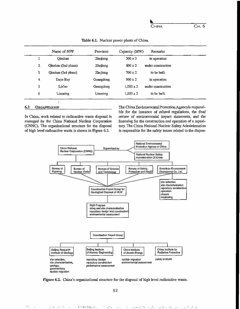
CHINA CH. 6
Table 6.1. Nuclear power plants of China.
NameofNPP Province Capacity (MW) Remarks
1
2
3
4
5
6
Qinshan
Qinshan (2nd phase)
Qinshan (3rd phase)
Daya Bay
Lin'ao
Liaoning
Zhejiang
Zhejiang
Zhejiang
Guangdong
Guangdong
Liaoning
300x2
600x2
700x2
900x2
1,000 x 2
1,000 x 2
in operation
under construction
to be built
in operation
under construction
to be built
6.2 ORGANIZATION
In China, work related to radioactive waste disposal ismanaged by the China National Nuclear Corporation(CNNC). The organizational structure for the disposalof high level radioactive waste is shown in Figure 6.2.
The China Environmental Protection Agencyis responsi-ble for the issuance of related regulations, the finalreview of environmental impact statements, and thelicensing for the construction and operation of a reposi-tory. The China National Nuclear Safety Administrationis responsible for the safety issues related to the dispos-
China NationalNuclear Corporation (CNNC)
Supervised by
National EnvironmentalProtection Agency of China
National Nuclear SafetyAdministration Of China
Everclean EnvironmentEngineering Co. Ltd.
Bureau of Safety,Protection and Health
Bureau of Scienceand Technology
Coordination Expert Group forGeological Disposal of HLW
R&D Programsiting and site characterizationrepository design and constructionenvironmental assessment
site selectionsite characterizationrepository constructionoperationclosuremonitoring
Coordination Expert Group
Beijing ResearchInstitute of Geology
site selection,site characterization,geology,geochemistrynuclide migration
Beijing Instituteof Nuclear Engineering
repository designrepository constructionperformance assessment
China Instituteof Atomic Energy
China Institute forRadiation Protection
nuclide migration safety analysisenvironmental assessment
Figure 6.2. China's organizational structure for the disposal of high level radioactive waste.
52

CHINA C H . 6
al of high level waste.
The CNNC is responsible for the transportation of HLWand spent fuels, reprocessing of spent fuels, vitrificationof liquid HLW, and final geological disposal of HLW.Under CNNC, four bureaus are involved in the disposalprocess: Bureau of Planning, Bureau of Nuclear Fuels,Bureau of Science and Technology and Bureau ofSafety, Protection and Health.
The Everclean Environment Engineering Corporation,attached to CNNC, is responsible for site selection, sitecharactererisation, construction, operation, closure andmonitoring of repositories of low and intermediate level,and high level radioactive waste.
A Coordination Expert Group was organized for thegeological disposal of HLW in 1986. The group is com-posed of experts from the Beijing Research Institute ofGeology, Beijing Institute of Nuclear Engineering ChinaInstitute of Atomic Energy, and China Institute forRadiation Protection. The group is responsible for R &D programs, site selection, research work related to sitecharacterization, repository design, environmentalassessment, safety analysis and performance assess-ment.
6.3 DEEP GEOLOGICAL DISPOSAL PROGRAM
In 1985, CNNC worked out an R & D program whichhas been called the Deep Geological Disposal (DGD) ofHLW (Yang, 1992). The program is divided into 4 phas-es:
Phase 1: 1985-2025 Site Selection and Site Characteri-zation
1. 1985-1986, Nationwide screening;2. 1986-1988, Regional screening;3. 1989-2010, District screening and preliminary site
characterization;4. 2011-2015, Pre-feasibility study of the pre-selected
district;5. 2015-2017, Licensing for site characterization;6. 2017-2023, Site characterization and suitability
study; and
7. 2023-2025, Licensing for the site.
Phase 2: 2025 - 2029, Repository Design
Phase 3: 2041-2050, Repository Construction
Phase 4: 2051- , Repository Operation.
Between Phase 2 and Phase 3, there is a 10-Year inter-val, during which an underground research laboratorywill be built near the selected site between 2028 and2033. A full-scale insitu test and disposal demonstrationwill be conducted in the laboratory between 2034 and2040. The final repository design will be revised afterthe work in the underground research laboratory is fin-ished.
According to China's policy, the final form of the dis-posed waste will be vitrified radiowastes after repro-cessing. The conceptual design for the HLW repositorywill be a shaft-tunnel model, which will be located inthe saturated zone in granite.
6.4 PROGRESS IN SITE SELECTION
According to the DGD Program, the site selection forChina's HLW repository is in progress, and granite isconsidered as the candidate host rock for the repository.The site selection process, started in 1985, is composedof 4 stages: nationwide screening, regional screening,district screening and site screening. At present, thethird stage has been reached, and the screening effortsare focused on the Beishan area, Gansu province innorthwest China.
6.4.1 Siting Criteria
Because of the high radiotoxicity and long half-life ofradionuclides in high level waste, sites for HLW reposi-tories should be selected very carefully. Siting guide-lines, or siting criteria, have been issued by many coun-tries or international organizations, such as USA,Sweden, EC, IAEA, etc. Taking China's situation intoaccount, as well as experience in other countries, weproposed preliminary siting guidelines that have beenfollowed during our work (Xu, 1992).
The general siting principle is that, under the effects ofnatural and human activities, the long term (100,000year) safety of the repository can be obtained, and thedisposed radioactive wastes can be prevented fromentering the biosphere and harming human beings.Furthermore, the following factors are considered in thesiting process. However, detailed and exact technicalrequirements and limits for these natural factors havenot been worked out.
Social Factors
• the distribution of nuclear industry in China;• the animal and plant resources, the potential mineral
53

CHINA CH. 6
resources;• the attitude of the public and the local government;• the requirement of national environmental protection
laws; and• the feasibility for construction and operation of the
repository.
Natural Factors
• natural geography, including topography, climate,hydrology etc.;
• geology, including crustal stability (earthquakes,active faults, etc.); and
• crustal stress, crustal thermal flow, host rock type,hydrogeology and engineering geology.
6.4.2 Progress in Site Selection
Since 1985, the site selection for China's HLW reposi-tory has progressed through three stages: (1) nationwidescreening (1985-1986); (2) regional screening (1986-1988); and (3) district screening (1989-present).
Nationwide Screening (1985-1986)
During this stage, the first work was the investigation ofthe site selection process conducted in other countries.Then, based on these experiences, and considering thedistribution of China's nuclear industry, the problems ofcrustal stability and social economic conditions, the fol-lowing five regions were selected for the repository (Fig.6.1): southwest China, Guangdong Area, Inner Mon-golia, east China, and northwest China. In this stage,granite, tuff, mudstone and shale were considered ascandidate host rocks.
Regional Screening (1986-1988)
Based on the work of Stage 1, twenty-one districts wereselected for further investigation within the five abovementioned areas:
1. Southwest China. Three districts were selected:Hanwangshan district, Zhongba district, and Hannandistrict. The potential host rocks are shale, biotitegranite, and plagioclase granite, respectively.
2. Guangdong Area. Since the Daya Bay NPP is locat-ed in this area and more NPPs are planned to be built,it was considered a potential area for the HLW repos-itory. The candidate geological formations are theFuogang granite body and the Jiufeng granite body.However, because of the rapid development in the
Guanadong province, this area may not be consid-ered for further investigation.
3. Inner Mongolia. The selected districts, includingParjiang Haizhi and Dabaolitu districts, are located incentral Inner Mongolia. The host rock is Hercyniangranite.
4. East China. In east China's Zhejiang and Anhuiprovinces, six districts have been selected: Lin'an,Gaoyu, Chenshi, Jiangshan, Guangde and Yixian.The host rocks include granite and tuff. The Chenshidistrict is located on a small island composed ofgranite.
5. Northwest China. The selected area is located innorthwest China's Gansu Province It is the mostpromising area for the construction of a HLW repos-itory. It is an arid gobi area with very low populationdensity and without an economic potential. A total offive districts have been selected for investigation:
• Toudaohe-Xiatianjinwei, biotite monzonitic gran-ite;
• Kuangqu, mudstone;• Baiyuantoushan, quartz diorite;• Qianhongquan, K-feldspar granite and plagioclase
granite; and• Jiujin, plagioclase granite.
District Screening (1989-present)
Since 1989, our work has been focused on northwestChina, with granite considered as the candidate hostrock. The following aspects of the area have been stud-ied: earthquakes, structural framework, active faults,crustal stability, lithology, hydrogeology, and engineer-ing geology. According to the crustal stability, we con-sider the Qianhongquan and Jiujin districts, located inthe southern part of the Beishan Folded Belt, as the mostpromising districts, and further work will be conductedin those areas.
6.5 BEISHAN AREA, GANSU PROVINCE, NORTHWEST
CHINA
6.5.1 Regional Geology
Regional Tectonics
The Beishan area in Gansu Province, is the preselectedarea for a HLW repository in China. Geographically, theBeishan area is located north of the town of Yumen innorthwest Gansu province, China. Tectonically, it islocated in the Erdaojin-Hongqishan compound anticline
54

CHINA C H . 6
of the Tianshan-Beishan folded belt (Fig. 6.3). The anti-cline strikes nearly east-west, with its core composed ofschist, laminated migmatite of the Laojunmiao Groupand Dakouzhi Group of pre-Changchengian age, and itslimbs are composed of schist, marble, quartzite andmigmatite of the Yujishan and Huayaoshan Groups ofpre-Changchengian age. In addition, along the limbs,there are Jiujin Caledonian magmatite (plagioclasegranite), Baiyuantoushan Caledonian magmatite (quartz
diorite) and Qianhongquan Hercynian magmatite (mon-zonitic and orthoclase granites). These magmatite rocksare the main candidate host rocks for the repository.
The border between the Beishan area and the HexiCorridor Transitional zone is the blind Sulehe fault.Within the Beishan area there are three east-west-strik-ing large scale ductile shear zones (DSZ), namely:South Erduanjin, Zhongqiujin-Jinmiaogou, and Erdojin-
J-K |2 | r |3 I P |4 I c |5 | And. |6 I 6 [7 I z |8 | Anz |9pyT~|lO| y* |H
Figure 6.3. Geological sketch map of the Beishan area, Gansu Province, northwest China containing the pre-select-ed area for China's high level radioactive waste repository. Legend: 1 - Tertiary and Quaternary sedi-ment; 2 - Cretaceous and Jurassic sandstone, shale and sandstone; 3 - Triassic conglomerate and peb-bly sandstone; 4 - Permian System; 5 - Carboniferous system; 6 - Pre-Changchengian schist, gneiss,marble and migmatite; 7 - Cambrian System; 8 - Sinian System; 9 - Pre-Sinian System; 10 -Yanshanian granite; 11 - Heicynian granite; 12 - Heicynian plagioclse granite; 13 - Heicynian ortho-clase granite; 14 - Heicynian Plagiolcase granite and two-mica granite; 15 - Heicynian granite diorite;16 - Caledonian plagioclase granite; 17 - Caledonian quartz diorite; 18 - gabbro vein; 19 - normalfault; 20 - reverse fault; and 21 - fault.
55

CH. 6
Figure 6.4. Moho discontinuity iso-depth contour map of northwest Gansu, China.
Hongqishan. The activity of brittle faults developedwithin the shear zones is a key factor affecting thecrustal stability of the area.
The Zhongqiujin-Jinmiaogou DSZ is east-west strikingwith a length of 90 km and a width ranging between 50and 2000 m. It was developed in monolithic gneiss,granite and sericite slate during the Hercynian period.The maximum depth of the shear zone is about 10 km.Several east-west striking brittle faults are developed inthe shear zone. However, these faults do not cut theQuaternary sediments, and no earthquakes withMs > 43/4 have been recorded along them, which indi-cates that they are not active faults.
The Erdaojin-Hongqishan DSZ is about 130 km longand has a maximum width of 7 km. The southern andnorthern borders of the shear zone are two east-weststriking brittle faults which are not active faults, either.
Crustal Structure
According to the main tectonic units, deep geophysicalfeatures and the crustal thickness, the crustal structure ofthe western Gansu province can be divided into theareas of Beishan-Alashan, North Qilian Mt., Hexi corri-dor, and Qilian. The selected area for the HLW reposi-tory is located within the Beishan-Alashan area. Thedepth contour of the crust in the area strikes NWW-EW.
The thickness of the crust is 47-50 km (Fig. 6.4), and itgradually increases from north to south with very littlevariation. The gravity anomaly is -150 to -225xlO'5 m/s2
(Fig. 6.5) with a gradient that is less than 0.6 mGal/km.On the gravity anomaly map, the contours are verysparse without obvious step zones, indicating that thereare no large faults extending to the depth of the crust.Based on these characteristics, the crust in the Beishanarea possesses a block structure with good integrity.
Earthquake Activity
Earthquakes are a demonstration of modern crustalmovement, and have a close relationship with tectonicmovement, especially with the intensive activityof largedeep-rooted faults. The Beishan area is located north ofthe Hexi Corridor earthquake zone. In this area, there isa lack of large active deep-rooted faults and strongearthquakes. According to data provided by the NationalSeismological Bureau of China, no earthquakes with Ms> 43/4 have been recorded in the Beishan area. On the"Seismic Intensity Regionalization Map of China(1:4,000,000)", the Beishan area is within a VI seismicintensity region (Fig. 6.6).
In sharp contrast to the Beishan area, the Hexi Corridorearthquake zone has several active NWW deep-rootedfaults. Along the North Hexi Corridor Great Fault, sev-eral intensive earthquakes took place, e.g., the M=7 1/4
56

CHINA CH. 6
95° 97° 99° 101° 103°
42°
40°
38°
36°1
• 'As
m—•Sc^f-x^:(Duanhang)
(USWimmm/w
^-fcCyumen)-
^ ^
/ L* Potential area
^ ^
16IP
1\7
0
i
i
i\ \ Mttll
1
6p 120km
( \ K/
X\\\ uv
Figure 6.5. Regional magnetic anomaly map of northwest Gansu, China.
earthquake in Mingle County in 1790; the M=7 1/2earthquake in Shandan County in 1954; and the M=6earthquake in Gaotai County in 756.
Neotectonism and Tectonic Stress Field
Neotectonism refers to the crust tectonic movementssince the Tertiary, including the horizontal and verticalmovement of the crust, volcanism, earthquakes andslides, etc. According to the neotectonic characteristics,the western Gansu Province can be divided into threeparts, namely: the Qilianshan blocking and intensiveuplifting region; the Corridor depression region; and theBeishan weakly uplifting region (Fig. 6.7). The selectedarea for the HLW repository is located within theBeishan weakly uplifting region. The land form of thearea is characterized by a flatter gobi and small hillswith elevations above sea level, ranging between 1000and 2000 m. The height deviation is usually several tensof meters. Since Tertiary time, it is a slowly upliftingarea without obvious differential movements. The rateof uplift for the crust in the area is about 0.6 - 0.8 mm/a,much lower than that of the Qilian region (1.5-1.8mm/a).
Comprehensive analysis of the structural deformation ofthe Cenozic faults and folds indicates that the area isundergoing horizontal compression at present, and theprincipal compressive stress is between 30 and 60
degrees. The data provided by the mechanism at thesource of earthquakes show that the direction of theprincipal compressive stress is about 40 degrees.
The strike of the main faults in the Beishan area isbetween 95 and 120 degrees. The angle between thedirection of the principal compressive stress and thestrike of the main faults, which is also called the super-imposed fault angle, ranges between 55 and 80 degrees.These are within the range of stable superimposed faultangles, suggesting that the main faults are stable andwill not undergo strike-slip displacement.
6.5.2 Regionalization and Evaluation ofCrustalStability
There are nine indices to evaluate the crustal stability ofan area, namely: (1) crustal structure and deep-rootedfaults; (2) Cenozoic crustal deformation; (3) Quaternaryblock and faults; (4) Quaternary and modern tectonicstress field; (5) Quaternary volcanoes and geothermalfields; (6) ground deformation and displacement; (7)gravity field; (8) earthquake strain energy; and (9) earth-quakes. According to these indices, crustal stability canbe divided into four classes: (1) stable region; (2) basi-cally stable region; (3) sub-stable region; and (4) unsta-ble region.
The western Gansu Province can be divided into three
57

CHINA CH. 6
42
41
94" 95" 96" 97"
. O
99" 100° 101°
42"
-Potential area
40'
99° 100" 101"
(Active fault)
O | M S 5 — 5 . 9
(Seismic risk zone)
1 M S 6 . 9 — 9
Figure 6.6. Seismic risk zoning of northwest Gansu, China.
regions (Fig.6.8): (1) Beishan stable region; (2)Yumenzhen-Huahai sub-stable region; and (3) HexiCorridor unstable region. The characteristics of theseregions are summarized in Table 6.2. From the table wecan see that the Beishan region has a block crustal struc-ture with good integrity and without regional activefaults, and it is a slowly uplifting region. The directionof the principal compressive stress in the area is about40 degrees, and the superimposed fault angles indicatethat the main faults will not have strike-slipe displace-ment. There are no gravity steps in the area, and norecords of intensive earthquakes either. The earthquakeintensity of the area is less than 6. These features showthat the crust in Beishan area is more stable than in thesouthern regions, and is a suitable candidate region for aHLW repository. On this basis, smaller districts can befurther selected for detailed site characterization.
Geological work in the Beishan area is at the very begin-ning stage, and the above data are only preliminaryresults. In the future, systematic site characterizationwork will be conducted year-by-year, to determine thesuitability of the Beishan area and to select the final sitefor a HLW repository.
6.6 OTHER STUDIES
The geological disposal of HLW is a long-term compre-hensive task. Li addition to site selection and site char-acterization, other studies are also being conducted on:
• Site preselection for an underground research labora-tory;
• Experiments on radionuclide migration (laboratoryand field);
58
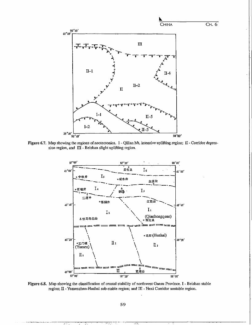
CHINA CH. 6
96°4040°40'
39°40'96°40' 98°00'
Figure 6.7. Map showing the regions of neotectonics. 1 - Qilian Mt. intensive uplifting region; II - Corridor depres-sion region, and HI - Beishan slight uplifting region.
97*00' 98:00'
•a'oo'
4OM0'
40'20'
40'00'
i6
\
\
\
II
(Qianhongquan)
\ \\ \ o#js(Huahai)
«=En& \ II2 \ IT(Yumen) \ \
n. \ \I L___—-!^_
41'00'
40!40'
40'20'
97°00' 98500'
Figure 6.8. Map showing the classification of crustal stability of northwest Gansu Province. I - Beishan stableregion; II - Yumenzhen-Huahai sub-stable region; and HI - Hexi Corridor unstable region.
5 9

CHINA C H . 6
Table 6.2 Crustal characteristics in western Gansu Province, China.
Characteristics Beishan Stable Region Yumenzhen-HuahaiSub-stable Region
Hexi CorridorUnstable Region
Crust structure and deep fault Crust is block structure withgood integrity, NW-strikingbasement faults aredistributed.
Crust is mosaic structure,with NE- and NW-strikingbasement faults.
Crust is crushed structurecontrolled by the north Qiliandeep fault and Aljin active fault.
Active fault and Quaternarycrustal movement
Superimposed fault angle
Gravity field
Energy VE(10-Verg)
Frequency(Ms >3.0)
Possibility forconstruction of HLWrepository
With few active faults, crustal With Sanweishan and Aljin With Aljin active fault, largestmovements of slowly uplift- active faults, crustal movement crustal movement is 4.7 mm/a,ing region with less than 0.1 is between 0.1 - 3.5 mm/a,mm/a.
55° - 80°
Gravity anomaly is smooth,gradient is less than0.5 mGal/km
Largest earthquake (Ms) 3.0
0.14
Possible
45° - 70° 80°
With regional positive Located in gravity anomalynegative gravity anomalies, step zones with negativethe gradient is 1 to 2 mGal/km gravity anomaly
10.59
6.0
25.54
Not possible Not possible
• Natural analogues;• Buffer/backfill materials and their geotechnics;• Speciation of transuranic elements in solutions;• Heater test; and• Models for safety and environmental assessments.
The safe disposal of high level radioactive waste is aworldwide challenging task. Although China has mademuch progress in this field, there is still a long way togo. For example, a policy act related to nuclear wastedisposal should be established, a more effective organi-zation should be formed to promote the required work,and a way should be explored to raise enough money forthe safe disposal of nuclear waste.
Information exchange is very important for the disposalof radwaste. China is willing to learn of the successful
experiences in other countries and to strengthen interna-tional cooperation. China is also willing to share its ownexperiences and achievements with other countries, forthe purpose of protecting the living environment ofhuman beings and protecting the Earth
REFERENCES
Yang, L. Progress in DGD program for high-level wastedeep geological disposal in China (1986-1991), in:Selected Works on the Study of Deep GeologicalDisposal of HLW in China, ed. by Sci & Tech.Bureau, China National Nuclear Corporation, pp.1-5,Dec. 1992. (in Chinese)
Xu, G. Investigation on site preselection of HLW repos-itory in China, in: Selected Works on the Study of
60
CHINA CH. 6
Deep Geological Disposal of ELW in China, ed. bySci & Tech. Bureau, China National NuclearCorporation, pp. ll-15.Dec. 1992. (in Chinese)
Luo, S., et al., Radioactive Waste Manacement, AtomicEnergy Press, Beijing, pp.1-9, 1995. (in Chinese)
Li, X., et al., Radioactive Waste Management, AtomicEnergy Press, Beijing, pp. 62-66, 1995. (in Chinese)
Wu, X., The future development for China's nuclearpower plants, China Nuclear Industry Newspaper,Nov. 1, 1995.
Li, X. et al., Research theory and method of regionalcrust stability, Geological Press, Beijing, 1987.
China National Seismological Bureau, The geophysicalexploration achievement of the crust and upper man-tle in China, Seismological Press, Beijing, 1986.
China National Seismological Bureau, Atlas of seismicactivity in China, China Science and TechnologyPress, Beijing, 1991.
Geological Bureau of Gansu Province, The geologicalmap and its explanation of Yumenzhen Quadrangle(1:200,000), 1972.
Geological Bureau of Gansu Province, The geologicalmap and its explanation of HouhongquanQuadrangle (1:200,000), 1969.
61

62
CHAPTER 7
SITE SELECTION OF LOW AND INTERMEDIATE LEVELRADIOACTIVE WASTE REPOSITORY IN THE REPUBLIC OF CROATIA
Antun Schaller
APO - Hazardous Waste Management Agency, Zagreb, Croatia
Abstract. The radioactive waste repository site-selection program in Croatia consists of two stages. The first, the sitesurvey stage, consists of: an exclusionary screening of the national territory, an internal evaluation of selected poten-tial areas, and an identification of potential sites, as well as the selection of a few preferred (candidate) sites whichwould be suitable for further detailed investigations. The second, the site evaluation stage, consists of all necessaryfield investigations and additional site-characterisation tasks at previously selected preferred sites. Eight potentialareas containing 42 potential sites have been selected in Croatia so far. Selection of 3-4 preferred sites is under way.Site selection methodology, including a description of applied exclusionary and comparative criteria, is also present-ed in the paper. The report is completed with basic information on current Croatian legislation and organisation of aregulatory body in the field, as well as with a brief characterisation of a few more perspective potential sites.
7.1 INTRODUCTION: SOURCES OF RADIOACTIVE
WASTE
The necessity of constructing a low and intermediatelevel radioactive waste (LLW/ILW) repository inCroatia has developed from the fact that there are twomain sources of radioactive waste materials. The firstgroup of sources is waste generated in the Republic ofCroatia itself, and the second, includes radioactive wasteoriginating from the operation of the Krsko NuclearPower Plant (NPP). Although the plant is situated in theneighbouring Republic of Slovenia, it represents a jointventure facility of both Slovenia and Croatia. Therefore,Croatia is obliged to find an appropriate solution to dis-pose of half of all radioactive waste generated during thelifetime of the NPP.
Radioactive waste in Croatia is derived mostly from var-ious nuclear applications: medicine, industry, agricul-ture and scientific research. In addition to this, there areabout 50,000 ionising smoke detectors distributed in950 buildings and some 500 ionising lightning arresters(protectors) installed on 320 buildings in the country.However, the total amount of radioactive waste whichhas been generated in Croatia so far is not more than 80m3, and its estimated gross activity is 2.3 x 10¹² Bq. Thewaste is composed of radionuclides like 152-154 Eu, usedin ionising lightning arresters; Ul Am, installed in ionis-ing smoke detectors; 192 Ir, 90 Sr,85 Kr and some others,
used in measurement and processing techniques inindustry; 137 Cs and 60 Co, used in numerous diagnosticand therapeutic methods in medicine, etc.
Basically, there are three radioactive waste disposalapproaches being practised in Croatia. The first, whichrefers to hospitals and research laboratories, is an ade-quate storage of waste until its activity falls to the back-ground level, and after that it is treated as commonwaste. The second approach is related to waste typescontaining long-lived radionuclides, which are beingproperly stored in two temporary storage facilities at sci-entific institutes "Ruder Boskovic" and the Institute forMedical Research and Occupational Health (both aresituated in Zagreb, the capital of Croatia). According toavailable data, there are some 500 institutions includingmore than 5,000 persons that are professionally in director indirect contact with radiation sources in Croatia.
The Krsko NPP is obviously the greatest producer of allradioactive waste expected to be disposed of in Croatia.Since the plant started operation in 1982, some 2,000 m3
of LLW/ILW with a total activity of about 3.6 x 10¹³ Bqhave been generated so far. However, it is realistic toexpect some 8,500 m3 of LLW/CLW to be generated inthe lifetime of the NPP." The total activity generated dur-ing the plant lifetime, could reach an estimated 1.5 x10¹⁴ Bq. In addition, roughly 11,000-12,000 m3 ofdecommissioned waste is expected to be produced in the
63

CROATIA C H . 7
plant by the end of its operation. This type of waste issupposed to be composed of 53% LLW, 36% ILW and11% high-level waste. The prevailing radionuclide is60Co, which is responsible for about 90% of the totalactivity of the waste. It is expected that Croatia will beresponsible for final disposal of some 10,000 m3 ofLLW/ELW, i.e. one half of the total LLW/ILW generat-ed during the lifetime of Krsko NPP.
7.2 ESSENTIAL STRATEGIC ISSUES IN RADWASTE
MANAGEMENT IN CROATIA
The strategy on radioactive waste management inCroatia was originally drafted by the APO - HazardousWaste Management Agency in 1992. It was recognisedthen that only a systematic and well-organised program,which would be based on responsible treatment withradioactive materials and tightly related to regulatorybodies and current legislation, can provide an accept-able approach to safe operation of nuclear facilities andradiation sources in different nuclear applications.
Basically, the strategy as developed in Croatia, includesthe following topics, i.e. tasks to be regularly and con-tinuously practised:
• identify all sources and precise quantities of radioac-tive waste in Croatia, as well as create and maintainan inventory of: radiation sources and radioactivewaste materials;
• define a legal framework, i.e. the system of responsi-bilities;
• establish the financing of a national radioactivewaste program;
• introduce and, if necessary, improve existing legisla-tion and regulations in the field of radioactive wastedisposal;
• develop the LLW/ELW repository, including all nec-essary activities like site selection, technical design,safety analysis etc.;
• foster public relations; and• give support to other radiation safety related actions
and programs.
The strategy has been rearranged according to existingIAEA documents, and is expected to be modified in thefuture according to forthcoming requirements and rec-ommendations of this international agency.
7.3 LEGISLATION AND REGULATORY FRAMEWORK
Regulations concerning radioactive waste management,
which are temporarilyy implemented in the Republic ofCroatia, have been partly taken over from the ex-Yugoslav legislation. In general, these regulations havebeen established according to world-wide practice andsupport other regulations concerned with environmentalprotection or the management of other wastes. Thebasic regulation is the, "Law on Ionising RadiationProtection and Special Safety Actions in NuclearEnergy Implementation", issued in 1984. From this law,17 regulations and codes of practice have been subse-quently derived. The new Croatian law on radiation pro-tection and nuclear safety is expected to be approved bythe end of 1996.
Documents to be emphasized here, due to their particu-lar importance in the field of site selection and radioac-tive waste repository construction and operation, are"Code of Practice on Conditions of Locating,Construction, Start-up and Operation of NuclearFacilities", "Code of Practice on Standard Format ofSafety Report and Other Documentation Needed forSafety of Nuclear Facilities", as well as "Code ofPractice on Methods of Collecting, Account,Processing, Storing, Final Disposal and Release ofRadioactive Waste Substances in the Environment, (allof them were issued in the period 1986-88). These reg-ulations went into effect according to the "Law onTaking Over the Federal Laws in the Field of HealthProtection, Applied in the Republic of Croatia asRepublic Laws".
A national regulatory body organising and controllingradioactive waste management, as well as radiation pro-tection issues, has not been established in Croatia as asingle institution covering all related issues. It consistsof sections of three separated governmental entities: theMinistry of Health, the Ministry of Economy, and theState Directorate for Environmental Protection.Unfortunately, there is no permanent body in Croatiawhich would co-ordinate activities of these ministries inthe field. The Sanitary Inspectorate, as a section of theMinistry of Health, is the competent national authorityfor radiation protection. The Ministry of Economy, i.e.Department of Nuclear Safety, is the competent nation-al authority for siting, construction, start-up, operationand closure of nuclear facilities. The competence of theState Directorate for Environmental Protection is direct-ed to issues related to environmental clean-up actions ofcontaminated sites, hazardous waste management, etc.It should be added that a few other ministries(Transport, Finances, Interior, etc.) are responsible forlicensing particular activities, which are incorporated in
64
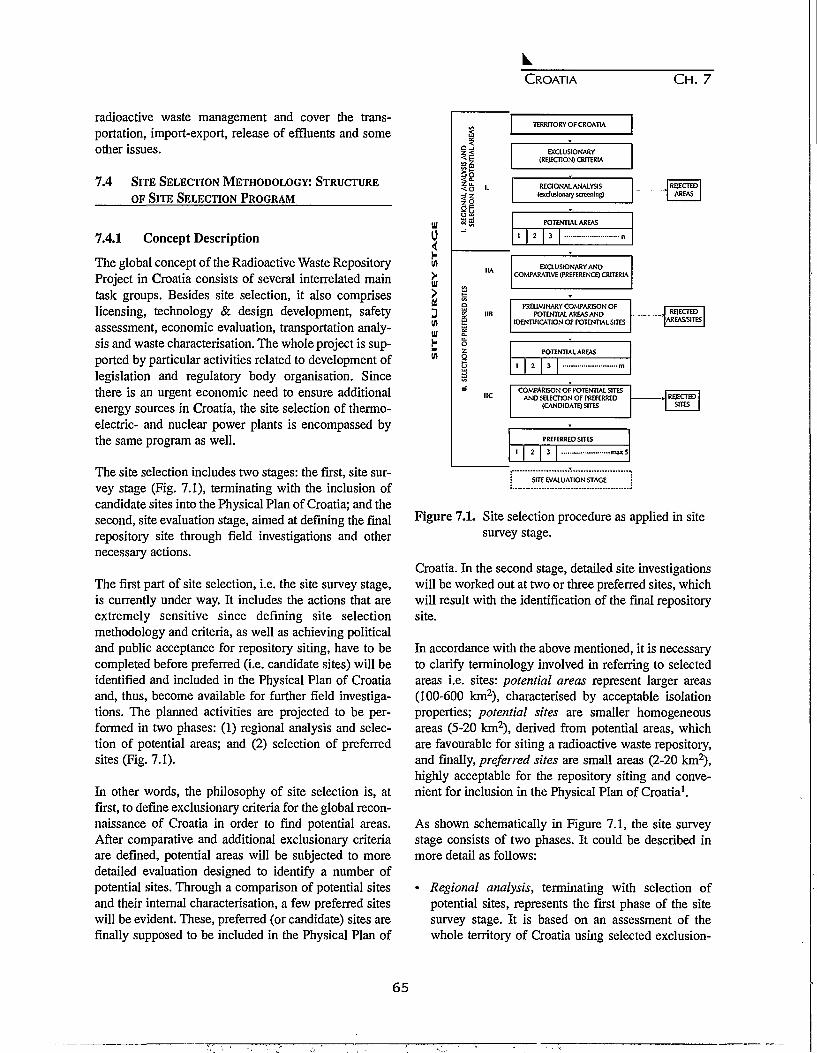
CROATIA C H . 7
radioactive waste management and cover the trans-portation, import-export, release of effluents and someother issues.
7.4 SITE SELECTION METHODOLOGY: STRUCTURE
OF SITE SELECTION PROGRAM
7.4.1 Concept Description
The global concept of the Radioactive Waste RepositoryProject in Croatia consists of several interrelated maintask groups. Besides site selection, it also compriseslicensing, technology & design development, safetyassessment, economic evaluation, transportation analy-sis and waste characterisation. The whole project is sup-ported by particular activities related to development oflegislation and regulatory body organisation. Sincethere is an urgent economic need to ensure additionalenergy sources in Croatia, the site selection of thermo-electric- and nuclear power plants is encompassed bythe same program as well.
The site selection includes two stages: the first, site sur-vey stage (Fig. 7.1), terminating with the inclusion ofcandidate sites into the Physical Plan of Croatia; and thesecond, site evaluation stage, aimed at defining the finalrepository site through field investigations and othernecessary actions.
The first part of site selection, i.e. the site survey stage,is currently under way. It includes the actions that areextremely sensitive since defining site selectionmethodology and criteria, as well as achieving politicaland public acceptance for repository siting, have to becompleted before preferred (i.e. candidate sites) will beidentified and included in the Physical Plan of Croatiaand, thus, become available for further field investiga-tions. The planned activities are projected to be per-formed in two phases: (1) regional analysis and selec-tion of potential areas; and (2) selection of preferredsites (Fig. 7.1).
In other words, the philosophy of site selection is, atfirst, to define exclusionary criteria for the global recon-naissance of Croatia in order to find potential areas.After comparative and additional exclusionary criteriaare defined, potential areas will be subjected to moredetailed evaluation designed to identify a number ofpotential sites. Through a comparison of potential sitesand their internal characterisation, a few preferred siteswill be evident. These, preferred (or candidate) sites arefinally supposed to be included in the Physical Plan of
TERRITORY OF CROATIA
EXCLUSIONARY(REJECTION) CRITERIA
REGIONAL ANALYSIS(exclusionary screening)
POTENTIAL AREAS
1 2 3
EXCLUSIONARY ANDCOMPARATIVE (PREFERENCE) CRITERIA
PRELIMINARY COMPARISON OFPOTENTIAL AREAS AND
IDENTIFICATION OF POTENTIAL SITES
POTENTIAL AREAS
1 2 3
COMPARISON OF POTENTIAL SITESAND SELECTION OF PREFERRED
(CANDIDATE) SITES
REJECTEDAREAS
REJECTEDAREAS/SITES
REJECTEDSITES
PREFERRED SITES
2 3 rrux5
SITE EVALUATION STAGE
Figure 7.1. Site selection procedure as applied in sitesurvey stage.
Croatia. In the second stage, detailed site investigationswill be worked out at two or three preferred sites, whichwill result with the identification of the final repositorysite.
In accordance with the above mentioned, it is necessaryto clarify terminology involved in referring to selectedareas i.e. sites: potential areas represent larger areas(100-600 km2), characterised by acceptable isolationproperties; potential sites are smaller homogeneousareas (5-20 km2), derived from potential areas, whichare favourable for siting a radioactive waste repository,and finally, preferred sites are small areas (2-20 km2),highly acceptable for the repository siting and conve-nient for inclusion in the Physical Plan of Croatia1.
As shown schematically in Figure 7.1, the site surveystage consists of two phases. It could be described inmore detail as follows:
• Regional analysis, terminating with selection ofpotential sites, represents the first phase of the sitesurvey stage. It is based on an assessment of thewhole territory of Croatia using selected exclusion-
65

CROATIA CH. 7
ary criteria ("exclusionary screening"). Areas whichdo not meet the requirements, defined by at least oneof these criteria, are eliminated. Remaining areas aredesigned as potential areas for further analyses.Regional analysis is based on appropriate informa-tion derived from topographic and other thematicmaps of Croatia on the scale 1:300,000.
• In the second phase - selection of preferred sites - allpreviously selected potential areas are checked bythe exclusionary criteria, and then evaluated on thebasis of more detailed data and large scale maps(1:100,000). Comparative criteria are applied to bothpotential areas and potential sites in order to identifypotential sites and preferred sites, respectively. Thistask is divided into three sub-phases as follows.
7.4.1.1 Selection of Parameters and Criteria.
Proposed parameters and criteria, applied in the identi-fication, selection and comparison of potential sites, aredefined by a special team of experts, composed of spe-cialists from different fields of interest (from geology tosociology). Both exclusionary and comparative criteriawere officially published in the Croatian official gazette"Narodne novine", No. 78/92. Comparative criteria aregenerally presented as requirements for achieving a cer-tain goal or a desired state. These goals can be definedas desirable conditions, and if a desirable condition cannot be achieved, the criteria should describe the degreeof acceptability (i.e. to what extent does the solutionapproach desirable conditions). The following fourgroups of comparative criteria have been formed inaccordance with basic aspects or dominant characteris-tics of the criteria involved:
A. Engineering aspects. Criteria comprised by thisgroup show whether the engineering requirementsfor acceptable radioactive waste disposal are met.Emphasis is placed on the economic issues of facili-ty construction and operation. Preference is given tosite characteristics which enable simpler and, thus,economically more acceptable solutions. Character-istics of the site can also affect, to a lesser extent, cer-tain safety aspects of the facility, but these can besuccessfully compensated by engineering interven-tions. Regarding this comparative criteria group,sites requiring simple and less expensive engineeringsolutions are preferred.
B. Safety-related aspects. In this group are collectedcriteria needed to determine whether the safetyrequirements for construction and/or operation of the
facility are met. Concordance with safety require-ments is checked during all phases of the site selec-tion program, and is very much evident in the licens-ing procedure of the facility. Emphasis is placed onevaluating the physical properties of an area thatcould have negative effects on facility safety.However, some site characteristics could have animpact on the choice of additional needed engineer-ing solutions that can influence on cost-benefitissues of construction and operation. Regarding thisgroup of comparative criteria, preferred sites arethose where facility safety is derived from more con-venient physical (natural) characteristics of the site,requiring a minimum of engineering intervention.
C. Environmental impact and acceptability in the imme-diate site area. This group includes comparative cri-teria showing whether the safety requirements, con-cerning the impact of the facility on the immediateenvironment, are met. Emphasis is placed on theenvironmental impact of the facility during its regu-lar operation as well as in cases of possible acci-dents. Site characteristics can also have an impact onthe degree of social acceptance. Concordance withsafety requirements must be confirmed throughoutall phases of site selection, and it will be evident incorresponding documentation (e.g. study on environ-mental impact assessment, safety reports, site per-mits etc.). Preference is given to those physical (nat-ural) site characteristics which provide less impacton the environment, as well as to existing andplanned land use types which could act positively onthe safety and acceptability of the site.
D. Acceptability of the facility site in the broader area.This group consists of comparative criteria thatassess the possible impact of the radioactive wastedisposal facility on the broader area. Emphasis isplaced on an analysis of present and planned land usetypes, as well as on the degree of social acceptanceregarding possible changes in the value of the area.Preference is given to present and planned land usetypes causing less conflict and therefore having agreater social acceptability, as well as to physicalcharacteristics that provide milder environmentaleffects resulting from the facility operation.
Comparison of potential sites: method of weightedcriteria
In this phase, it is necessary to choose the most appro-priate method of site evaluation and comparison. There
66
CROATIA C H . 7
are several techniques and methods in world practice.On the basis of experience acquired in Croatia andSlovenia in the field during the last few years, a multi-ple criteria analysis has been chosen as the most effec-tive. In particular, the method PROMETHEE (i.e."Preference Ranking Organisation Method forEnrichment Evaluations"), created by J.P. Brans and P.Vincke, has been applied in our case. The method rep-resents a computerised analysis of a multiple criteriatechnique and decision-making methods. Thus, objec-tivity in site selection and assessment has been success-fully achieved. The method is based on the applicationof numerous criteria in order to express interrelationsamong alternatives, indicating a group of "better" solu-tions.
The relative significance of each criterion is expressedby assigning to it a corresponding weighting factor. Thevalues of the weighting factors are defined by applyingthe rating method, and are based on decisions of theexperts. After discussion, members of the expert teampropose weighting factors for all comparative criteria.As result, a special co-ordinating group adopts the finallist of weighting factors (as is presented in Table 7.1;see the section "Comparative Criteria"). It is obviousfrom the Table that the expert team concluded that cri-teria group C ("Environmental impact and acceptabilityin the immediate site area") is the most important witha total weighting factor for this group of 52.5% . This isfollowed by the group B ("Safety related aspects") witha 30.0%. share. The acceptability of broader site area(group D) is expressed by a total weighting factor of9.5%, since it is assumed that LLW/ELW repository willhave almost no impact on the broader site area. Finally,the importance of engineering aspects is estimated to beonly 8% because it is expected that the repository wouldnot require considerable civil-engineering interven-tions.
7.4.1.2 Assessment and Comparison of PotentialAreas and Identification of Potential Sites
In order to get more precise information, the first task inthis sub-phase is to check on the exclusionary criteriaapplication which would be based on more detailedmaps (on the scale of 1:100,000). Geologic characteris-tics, i.e. engineering/geologic properties - includinglithological and geomorphologic, tectonic and seismic,as well as hydrogeological characteristics of the select-ed sites, are of special interest.
7.4.1.3 Assessment and Comparison of
PotentialSites Followed by Selection ofPreferred (Candidate) Sites.
In this sub-phase, more detailed data on sites, previous-ly chosen in sub-phase 7.4.1.2, are collected in order toperform a comparative assessment of their acceptabili-ty. The on-site investigation of all potential sites shouldbe carried out, and the exclusionary criteria are sup-posed to be checked once again. In the field of potentialsites, the previously determined reference points shouldbe re-evaluated. With regard to basic safety site charac-teristics (lithology, hydrogeology, risk of flooding), acertain number of potential sites is expected to beexcluded due to their lower quality, by comparison withthe others. It has already been decided that not morethan 3-5 preferred (candidate) sites will finally be pro-posed for further detailed on-site investigations.
The final comparison of potential sites, as well as thefinal selection and proposal of preferred sites, will beperformed after validation of both criteria and weight-ing factors by a competent governmental/parliamentarybody. Comments on the involved criteria that wouldprobably result from public debate and discussions withexperts will be thoroughly re-examined afterwards bymembers of the expert team. If agreement is reached,these comments will be accepted. In that case, the mainsections of the site survey procedure will be reanalysed.
7.5 SITE SELECTION AS A MULTIPLE CRITERIA
ANALYSIS
7.5.1 Some Basic Facts about Croatia
The Republic of Croatia (56,538 km2) is situated in thesouthern part of central Europe. It includes three majorphysical-geographical regions: Pannonian basin, Di-naric Alps and the Adriatic coast. As part of formerYugoslavia, it proclaimed its independence in June1991. There are about five million inhabitants living inCroatia, with an average population density of 80 inhab-itants per square kilometre. Due to its unusual shape,the total length of the Croatian border is very long -2,100 km. The neighbouring countries to Croatia areSlovenia, Hungary, Serbia, Bosnia-Herzegovina andMontenegro, as well as Italy (the border with Italy runsalong the Adriatic sea). The major Croatian cities areZagreb, the capital (900,000 inhabitants), Split(250,000), Rijeka (200,000), Osijek (120,000), Zadar(80,000) and Pula (70,000) (Fig. 7.2). Farming, forestry,fishery, industry, shipbuilding and tourism are the maineconomic activities. Industry, including mining and
67

CROATIA CH. 7
Table 7.1. List of comparative criteria and their weighting factors.
Group:Percent:
1. Transportation1.1 Transportation or radioactive waste
2. Meteorolosv and hvdroloav2.1 Hydrological issues2.2 Meteorological issues
3. Geoloev and seismoloev3.1 Seismotectonics and seismics3.2 Soil mechanics and slope stability3.3 Hydrogeology
4. Demography4.1 Population density
5. Present and planned land use tvpes5.1 Settlements5.2 Tourism5.3 Agriculture5.4 Forestry5.5 Industry and mining5.6 Infrastructure5.7 Special purposes
6. Environmental protection6.1 Protection of natural heritage6.2 Protection of cultural heritage6.3 Soil properties6.4 Bio-ecological values of the site6.5 Radiological aspects
A8.0%
A.3.1 - 4.0A.3.2 - 4.0
B30.0%
B.2.1 - 7.5B.2.2 - 2.8
B.3.1- 5.9B.3.2 - 9.8
B.6.3-4.0
C52.5%
C.1.1. - 3.7
C.2.1 - 3.2C.2.2 - 0.8
C.3.3 - 12.1
C.4.0. - 5.4
C.5.1 - 4.4C.5.2-3.3C.5.5 - 2.6C.5.4 - 2.2C.5.5 - 1.1C.5.6 - 1.5C.5.7 -1.1
C.6.1 - 3.0C.6.2 - 1.6C.6.3 - 2.4C.6.4 - 2.5C.6.5 -1.6
D9.5%
D.5.1 - 3.5.D.5.2 - 2.5
D.6.1 - 2.5D.6.2 - 1.0
TOTAL100%
3.7%
14.3 %
35.8%
5.4%
22.2%
18.6%
energy production, produces 44% of the national grossincome.
7.5.2 Geological Background
Sedimentary rocks prevail in the geologic structure ofCroatia, occupying 95% of its surface lithology.Moreover, it should be emphasized that the distributionof Mesozoic carbonate rocks, like limestone anddolomite, is the leading rock type throughout the south-ern part of the country (i.e. south from Karlovac.) Themorphology of this area is characterised by karst (Fig.7.3), occurring in two basic varieties: shallow karst,covered by soil in the interior parts, and thick, exposedkarst stretching along the Adriatic coast. An irregular
hydrogeology and very sensitive mechanisms have aremarkable impact on the quality of surface- andground-water and control some specific bio-lithologicalprocesses (e.g. formation of travertine). Consequently, alot of human activities being practised in the area even-tually leads to considerable environmental pollution.
In the northern part of the country in the Pannonianbasin, fluvial, erosional and aeolian clastic sedimentsare dominant, particularly in the lowlands along therivers Sava and Drava, as well as in the east Croatianplain. The central Slavonic massifs (Papuk, Krndija,Psunj, Pozeska gora), in the heart of northeasternCroatia (known as Slavonia), are mainly composed ofold Paleozoic igneous (granite, basalt, etc.) and meta-
68

CROATIA C H . 7
Hungary
Figure 7.2. Croatia with its major cities.
morphic rocks (crystalline schists, gneiss, etc.) (Fig. 7.3).
The territory of Croatia is an unstable area from thestandpoints of both tectonics and seismicity. Severalmajor longitudinal faults run in a NW-SE direction, inboth the northern and southern parts of the country.Where they intersect, transverse faults are in many casescharacterised by geothermal springs. Earthquakes asintensive as VHI-X MCS can be expected in most of theAdriatic coast region (southern Dalmatia, in particular),but they can also occur in some areas of northwesternCroatia.
During site selection for a radioactive waste repository,attention should be paid to both repository designoptions and available rock types. The leading principle inboth cases is to ensure environmental safety, and not tosave money. Almost half of Croatia is not convenient fora repository siting due to the prevailing carbonate lithol-ogy, karst morphology and the consequent irregular cir-culation of groundwater. Since the remaining flatlands
are generally unsuitable because of major infiltrationwith high water-tables (along the rivers Sava, Drava andDanube), the areas of interest are the previously men-tioned mountains of the country's interior, Papuk,Krndija, Psunj and part of Bilogora as well as Mosla-vacka gora, that is situated somewhat to the west. Allthese mountains, except Bilogora, are horst-structurescomposed to a great extent of granite, gneiss and schist2.
7.5.3 Site Acceptability Assessment
In the site selection process, it would be insufficient tolocate only a host-rock capable of providing waste con-tainment, i.e., to keep water away from the waste.According to the accepted approach, it is recognized thatthe entire system, i.e. waste form and package, host-rock,geological formations of the broader area, and environ-ment of the region, should provide waste containment. Inkeeping with this philosophy, the applied criteria shouldaddress all site characteristics that contribute to wastecontainment and insulation. These characteristics
69

CROATIA CH. 7
Figure 7.3. Geologic map of Croatia:. 1- Precambrian (metamorphic rocks); 2 - Paleozoic (clastites, additionallycarbonates); 3 - Paleozoic (igneous rocks: granite); 4 - Triassic (carbonates, add. clastites); 5 - Jurassic(carbonates, add. igneous clastites); 6 - Cretaceous (carbonates, add. clastites/flysch); 7 - Cretaceous(igneous rocks: basalt); 8 - Paleogene (limestones); 9 - Paleogene (clastites, flysch ) 10 - Paleogene(limestone clastites, limestones); 11 - Neogene (clastites, limestones); 12 - Pleistocene (clastites/most-ly non-cemented); 13 - Holocene (clastites/mostly non-cemented.) Tectonics: a - normal faults; b -reverse faults and thrusts; c - reverse faults and thrusts (submarine).
include geotechnical and socio-economic concerns. Inthe application of these criteria, greater considerationshould be given to those factors that directly influencethe safety of the repository than to those criteria whichaffect only repository cost and timeliness.
In the final analysis, repository licensing and operationcan not be performed until it is demonstrated that thetotal waste disposal system, including the waste formand its packaging, design of engineered facilities andbarriers, as well as the multiple natural barriers, will ade-quately protect public health and safety and preserve the
quality of the environment3.
7.5.4 Exclusionary Criteria
There are ten exclusionary criteria to be applied in thefirst phase of the site selection process, i.e., in a regionalanalysis of the whole territory of Croatia, where the aimis to reject all areas that do not meet requirements ofthese criteria. The exclusionary criteria are divided, sim-ilarly to the previously discussed classification of com-parative criteria, into four groups: A - Engineeringaspects; B - Site safety related aspects; C - Site accept-
70

CROATIA CH. 7
ability; and D - Facility safety. These four aspectsinvolve three basic principles for repository siting: cost-benefit ratio, acceptability and safety. The following is abrief description of each criteria with examples of theexcluded areas that result when the territory of Croatia isanalyzed.
1. Meteorological and hydrological criteria:Flooding (Group D)
All natural floodplain areas excluded (assuming repeatperiods at 1,000 year intervals), regardless of whetherthey are protected or not.
Comment: The LLW/ILW repository must be situatedbeyond the reach of floods. Hence, all natural flood-plains, as well as those areas where accumulations ofwater are planned, are excluded. Areas, where it is notlikely to prove a low risk of flooding by additional inves-tigations, are also excluded. The risk of flooding is sup-posed to be studied throughout the site selection pro-gram.
Excluded areas: Large lowland zones along the majorCroatian rivers of Sava and Drava, as well as the Danubein Baranja region; and numerous sinks in karst regions,which are characterised by seasonal flooding.
2. Geology and(Group A)
seismology: Seismotectonics
Areas with maximum potential earthquake intensityequal to or higher than IX MCS, are excluded.
Comment: Elimination of areas that are potentiallyaffected by strong earthquakes is also safety related andshould be thoroughly evaluated in further investigations.From technical and economic viewpoints, the cost offacility construction increases exponentially as theexpected earthquake intensity increases; therefore, theexpected maximum intensity DC MCS has been taken asthe highest acceptable value.
Excluded areas: Most of southern Croatia (Dalmatia),including the coastal zone, Kvarner bay in the northAdriatic, as well as the so-called "Balaton morpho-linea-ment", i.e., the mountains of Medvednica and Kalnik innorthwest Croatia. Some locations in northeast Croatia(Slavonia) are also excluded by this criterion.
3. Geology and seismology: Neotectonics (Group A)
Zones characterised by known active faults are excluded.
Comment: It is known that in neotectonically activeareas, as well as in the vicinity of regional and even localactive faults, dislocations and rock cracking are possible.These events could cause damage to a waste disposalfacility. This safety related criterion is also supposed tobe applied (or re-checked) in subsequent phases of thesite selection program. In addition it should be men-tioned that the term "active fault", as used here, is relat-ed to a zone that is a few kilometres in width andincludes two or more parallel faults. Earthquakes withmagnitudes 5.5 - 7.0 can occur along these faults.
Excluded areas: Southern Croatia, including the coastalzone, Kvarner bay, parts of northwest Croatia, as well assome spots in northeast Croatia - Slavonia.
4. Geology and seismology: Lithology and geomor-phology (Group A)
Option 1: Shallow ground disposal: Areas characterisedby an increased erosion rate due to lithology (prevailingrock types) andlor relief dynamics, as well as areas com-posed of rocks which are unstable under natural condi-tions (e.g. which are not resistant to weathering etc.)after the completion of civil-engineering works, areexcluded.
Option 2: Tunnel-type disposal: Areas characterised byland slides and rock falls are excluded if it is thought thatthese processes could pose a hazard to repository struc-tures.
Comment: Lithologic, geomorphologic and geotechniccharacteristics, along with hydrogeological properties ofan area, are considered the most important criteria relat-ed to the siting of an LLW/CLW repository. The upperPliocene and Quaternary clays and Neogene marls(lower Pontic "Abichi" sediments, in particular) are con-sidered the most suitable for a shallow-ground facilitysiting in Croatia. For the tunnel-type repository, areascomposed of granites and some other igneous rocks aremost suitable. Some metamorphic rocks like gneiss andsome types of schists could also be used for this purpose.Areas which do not meet these requirements are exclud-ed.
Excluded areas: Lowlands along the Sava and Dravarivers in the interior of Croatia, due to possible liquefac-tion caused by earthquakes; hills which surround themountains of Zumberacka gora, Medvednica, Kalnikand Ivanscica in northwest Croatia and are composed ofNeogene and Quaternary sands, clays and marls; flyschbelts in the Istrian peninsula (west Croatia), parts of allu-
71

CROATIA CH. 7
vial zone of the Sava river and its tributaries, and somesections of river valleys in Istria and Dalmatia and fewother spots in the karst regions.
5. Hydrogeology: Protection of water-bearing layers(Group B)
Areas containing protected sources of drinking waterare excluded. In order to preserve groundwater frompossible radioactive pollution, a disposal facility cannot be situated in an area containing significant water-bearing layers of any type.
Comment: Hydrogeologic properties of any potentialsite significantly influence the selection of repositorydesign, and also represent specific mechanisms for theassessment of possible environmental pollution.Therefore, areas of high risk for groundwater pollutionare excluded at the very beginning of the site selectionprogram. In the case of a tunnel-type repository, suitableareas are those which are composed of solid, primarilyimpermeable rocks having no secondary porosity. Forshallow-ground disposal, the more preferable areas arecomposed of thick clays and marls without majoraquifers. The possible impact on springs and wells, inaddition to the necessary protection measures, are exam-ined in all further site specific investigations.
Excluded areas: Parts of the country characterised bymajor aquifers where groundwater is not protected bynear-surface layers or by formations of high porosity.This means almost all of the lowlands along the rivers ofMura, Drava and Danube, the extreme upstream anddownstream sectors of the Sava river zone, as well aspractically the entire karst area, which represents in factthe southern half of the country.
6. Demography: Population density (Group C)
Areas characterised by a population density of 80inhabitants per square kilometre (i.e., the average valuefor Croatia) or more, within a 20 km radius around thefacility site, are excluded.
Comment: One of the preferred factors in lowering therisks of nuclear facilities to human health and environ-mental preservation is to have as low a population den-sity as possible. For that reason the more densely popu-lated areas of Croatia are excluded. The population den-sity in the vicinity of a facility will be re-evaluated insubsequent phases of the site selection program.
Excluded area: Broad areas around major Croatian cities
and the towns of Zagreb, Split, Rijeka, Osijek, Zadar,Pula, Dubrovnik, Karlovac, Sisak, Varazdin andSibenik, which are all characterised by population den-sities higher than 80 inhabitants/km2.
7. Present and planned land use types: Special pur-poses (Group B)
Areas designated for special purposes, including theirprotected zones, are excluded.Comment: Certain areas are of special interest fornational defence. All areas which are, or could be, inconflict with this criterion are excluded.
8. Present and planned land use: Mining explorationof ores and minerals (Group BX
Areas in zones of present or planned mining includingexploration of minerals, gas, oil, coal etc., are excluded.
Comment: Exploration of ores and minerals could havean impact on the LLW/ELW disposal facility safety, andin this way make the potential site economicallyunfavourable. Some limited areas along the Sava andDrava rivers have been excluded by this criterion due toexisting or perspective exploration of oil and gas.
9. Environmental protection: Protection of naturalheritage (Group B)
National parks, natural parks and other specific natur-al areas of common interest, are excluded.
Comment: In early phases of the site selection program,it is necessary to identify areas that are protected as anatural heritage and are therefore not suitable for sitinga LLW/ILW disposal facility. This criterion is closelyrelated to the requirements defined in the NaturalProtection Law, which mentions specific, ecologicallysensitive areas that should be continuously protected.
Excluded area: National parks (Brijuni islands, Risnjakmountain, Plitvicka jezera lakes, Velebit mountain,Kornati islands, Krka river and part of Mljet island), nat-ural parks (parts of some mountains, rivers, swamps,islands, etc.) and other significant natural reservations(landscapes, forests, etc.)
10. Environmental protection: Protection of culturalheritage (Group B)
Areas containing monuments of cultural heritage whichare registered in the List of World Cultural and Natural
72

CROATIA C H . 7
Heritage, as well as those that are of an extraordinarynational importance, are excluded.
Comment: It is necessary at the very beginning of thesite selection process to define areas which are protect-ed as monuments of cultural heritage, since they have tobe avoided as potential sites for the LLW/BLW disposalfacility. The term "cultural heritage", as used here, isapplied not only to an object of interest itself, but also tothe surrounding area.
Excluded area: Monuments of cultural heritage present-ed on the List of World Cultural and Natural Heritage(e.g. Diocletian's Palace in Split and the old town ofDubrovnik), larger areas known by their specific land-scape, as well as culturally, historically and aesthetical-ly valuable locations.
7.5.5 Comparative Criteria
After potential sites are identified by the process ofexclusionary screening (including re-checking of pre-liminary chosen sites by the same exclusionary criteria,but applied now on more detailed maps), they have to besubjected to a comparative analysis, i.e. an evaluationbased on an application of comparative criteria. Asalready mentioned, these criteria were defined by theexpert team members and divided into four aspectgroups: A - Engineering, B - Safety, C - Environmentalimpact and acceptability in the immediate site area, andD -Acceptability of the site, i.e. the facility in the broad-er area. The criteria were then classified into six the-matic groups, and, according to their importance, weregiven corresponding weighting factors, also defined bythe expert team. A total of 28 comparative criteria (seeTable 7.1) were applied in the site selection program.Table 7.2 provides a list of topics to which the compar-ative criteria in Table 7.1 were applied.
7.6 DESCRIPTION OF COMPLETED ACTIVITIES
The activities on radwaste repository site selection inCroatia began in 1988. Until 1991, Slovenia and Croatiahad not been proclaimed as independent states, and thepreliminary activities on repository site selection in bothrepublics (i.e. states) were managed by the Inter-repub-lic Coordination Commission in order to harmonise thesite selection procedures in both countries. Li Croatia,the Ministries of Energy and Physical Planning, throughthe Croatian Electricity Management Board, were com-mitted to the Institute for Urban Planning of Croatia toperform the study "Site Screening, Investigation andAssessment of Site Suitability of Fossil Fuel Power
Table 7.2. Application of comparative criteria.
Identification Comparative CriterionNumber to be applied to:
A.3.1.A.3.2.B.2.1.B.2.2.B.3.1.B.3.2B.6.3.C.I.I.C.2.1.C.2.2.C.3.3.C.4.0.C.5.1.C.5.2.C.5.3.C.5.4.C.5.5.C.5.6C.5.7.C.6.1.C.6.2.C.6.3.C.6.4.C.6.5.D.5.1.D.5.2.D.6.1.D.6.2.
Seismic ActivitySoil mechanicsRisk of floodingExtreme meteorological phenomenaNeotectonic activityLithology and geomorphologyChemical aggressiveness of soilsTransport of radwasteDistance to surface waterwaysDispersion in atmospherePresence of infiltrationPopulation densitySettlementsTourismAgricultureForestryIndustry and miningInfrastructureSpecial purposesNatural heritage protectionCultural heritage protectionPlant production (soils)Bioecological issuesRadiological issuesSettlementsTourismNatural heritage protectionCultural heritage protection
Plants and Nuclear Facilities in the Territory of theRepublic of Croatia". The goal of the study was theidentification of preferred sites for thermal and nuclearpower plants, as well as a radioactive waste repository,which might later be nominated for this purpose in thePhysical Plan of Croatia. The Institute for UrbanPlanning created a special team of experts, to define andassess selection criteria, as well as to act decisively inidentifying potential areas, potential sites and preferred(candidate) sites. The set of exclusionary criteria wasdefined by July 1989, and validation of criteria was car-ried out by the Croatian Government.
Using the method of exclusionary screening for thewhole territory of Croatia (Fig. 7.1), the resulting mapshowing areas which "survived" exclusion of inconve-nient regions was obtained, and eight potential areas
73

CROATIA C H . 7
Figure 7.4. Locations of eight potential site areas for a LLW/ILW repository.
(Petrova gora, Trgovska gora, Zrinska gora, Bilogora,Moslavcka gora, Papuk-Krndija-Psunj, Pozeska gora,Dilj) were finally identified in autumn 1990 (Fig. 7.4).Collecting additional data on potential areas and defin-ing comparative criteria were the main project activitiesbeing worked out during the rest of 1990 up to August1991. Site selection methodology and criteria wereexamined by the IAEA Radioactive Waste ManagementAdvisory Programme (WAMAP) in the spring of 1991,and were assessed as high-grade. Since autumn 1991,i.e. after the fall of former Yugoslavia, the newly estab-lished APO - Hazardous Waste Management Agencystarted to manage the remaining part of site selectionprogram in Croatia. On the basis of previously per-formed actions, it was possible in autumn 1994 to iden-tify 42 potential sites, which are dispersed within theabove mentioned eight potential areas (Fig. 7.4).Consequently, the only task remaining in the second
phase of the site survey stage is to select 3-5 preferredsites, which will be suitable for further detailed on-siteinvestigations. This task should be done by the end of1996.
7.7 CONCLUSIONS
The siting of a radioactive waste repository in Croatiahas been adjusted to the requirements derived fromphysical (regional) planning documentation. The siteselection program is composed of two stages: (1) a sitesurvey, terminating with the inclusion of preferred (can-didate) sites in the Physical Plan of Croatia; and (2), siteevaluation to define the final repository site throughfield investigations and other necessary activities. Therehas been very slow progress in carrying out this programdue to certain circumstances in the country and theentire region, and the preferred sites will not be defined
74

CROATIA CH. 7
before the end of 1996.
The system approach includes a simultaneous prepara-tion of the repository technical design, performanceassessment and some additional activities. Furthermore,it would be preferable to find a site that would be con-venient for a combined disposal facility, not only forradioactive waste, but also for other types of hazardouswastes. An interdisciplinary approach is applied in thesite selection, where all relevant topics from geology tosociology are involved in the program. A standard sitescreening technique has been applied in this process.The stepwise approach to the site selection is based onvalidation of every single step (starting from the entirestate territory), and is supposed to be terminated withthe selection of few preferred sites. The program isbased on the implementation of both exclusionary andcomparative criteria that have been selected by a specialteam of experts.
The selection of a radioactive waste repository site isconsidered as a process leading to an optimisation ofland use policy of the country in the light of attaining anoptimum method of exploitation of the nationalresources. In addition, the site selection is conceived asan action supposed to be internationally verified, aimingto strengthen our proclamation that, "We are doing justthe same as other countries". It is also worth mentioningthat the radioactive waste repository site selection is partof a useful project directed to site selection of nuclear-,coal- and gas-fired power plants. Anyhow, a regularlyperformed site selection process could be assessed as aprerequisite for possible future nuclear energy programin Croatia.
Considerable effort is being given to a program of pro-viding full, complete, continuous and honest informa-tion to the public. Necessary preparations for involve-ment of local communities into the site selection processhave already been completed. Hence, democratisation inthe siting process of a radioactive waste repository, as acontroversial facility, could be achieved in the best pos-
sible way. It also includes the determination of incen-tives needed by communities living in the vicinity of therepository. In addition, being concerned of their possibleNMTOO ("Not in my Term of Office") behaviour, weare also very careful, and are doing our best to prevent"premature" exposure of politicians to the consequencesof the expected NIMBY effect.
Finally, we are facing the specific problem of somemalicious attempts, done mostly by certain politicians,or "experts," to explain the radioactive repository siteselection program in Croatia as an action based, aboveall, on an ethnic criterion. It must be emphasised that inspite of arguments derived from an extremely irrationalapproach, these accusations could attain the end, whichis not, in fact, to stop or aggravate the site selectionprocess itself, but to deteriorate the very sensitive polit-ical and military situation in the broader region.
REFERENCES
1. Site Survey Stage of the Siting Process for Low- andIntermediate Level Radioactive Waste DisposalFacilities, The Institute for Urban Planning ofCroatia, Zagreb, 1991.
2. Saler A., General approach and site selection criteriafor low- and intermediate-level radioactive wasterepository in Yugoslavia, in Geological Problems inRadioactive Waste Isolation: A World Wide Review,Lawrence Berkeley Laboratory Report LBL-29703,Ed. RA. Witherspoon, pp. 173-179,1991.
3. DOE (U.S. Department of Energy,) NWTS Criteriafor the Geological Disposal of Nuclear Wastes: Site-qualification Criteria, ONWI Staff, 1980.
4. IAEA (International Atomic Energy Agency). TheMission Report Radioactive Waste ManagementAdvisory Program (WAMAP), Vienna, 1991.
75

76
CHAPTER 8
GEOLOGICAL DISPOSAL OF RADIOACTIVE WASTE IN
THE CZECH REPUBLIC
Ales Laciok, Lumir Nachmilner, and Frantisek Woller
Nuclear Research Institute, Rez, Czech Republic
8.1 INTRODUCTION
The Czech Republic has appeared on the map of CentralEurope since 1/1/1993 after the split of Czechoslovakiain two parts; the other is the Slovak Republic. With its10.3 million inhabitants and a territory of 78,864 km2,the country is comparable with e.g. Belgium,Switzerland or Austria. The Czech Republic belongs tothe more successful transformed states of the formerSoviet block: A steady decrease of inflation (9% in1995), increase of GNP (4.6% in 1995), non-deficit bud-get and low unemployment (3.5% in 1995) are signs ofa stabilized economic situation.
The intensive industrialization of the country requiresamong other things, a high production of energy: theinstalled capacity is 13,793 MWe, of which 1,760 MWeis nuclear. Consumption of electric power, some 58TWh in 1995, is provided from internal resources for94%, of which nuclear plants provide approximately21%. This power is produced in NPP Dukovany withfour VVER 440 MWe blocks. Another nuclear facility isunder construction: the Temelin plant shall operate twoVVER 1000 MWe units. After their connection to thegrid in 1997-8, the share of electric power produced byNPP should reach almost 45% of the national electricpower production, and some coal burning plants will bedecommissioned.
8.2 ORGANIZATIONAL STRUCTURE OF WASTE
MANAGEMENT
Radioactive wastes are produced and managed in theCzech Republic in three independent fields: uraniummining and milling, nuclear power plant, and other insti-tutions (medicine, research, industry). The governmentcontrols all activities through the Ministry of Trade andIndustry. The owner of uranium production facilities,DIAMO, is a state enterprise. The state also owns67.46% shares of CEZ, which is the operator of
Dukovany and Temelin NPPs. The company legallyresponsible for collection and disposal of institutionalwaste, NYCOM, is controlled by a "golden" share of5% by the Czech state as well. Independent supervisionof all activities is performed by the State Office forNuclear Safety which regulates and licenses both fromthe point of nuclear and radiological safety. TheMinistry of Environment indirectly influences theseactivities, as it is responsible for decisions in theEnvironmental Impact Assessment procedure.
The waste producers are obliged to treat, condition anddispose all radioactive waste at their own expense.However, especially for disposal activities, the responsi-bility may be transferred to another licensed organiza-tion. This procedure is obligatory for the disposal ofinstitutional waste, as NYCOM is the only licensedoperator of repositories for these wastes.
8.3 WASTE PRODUCTION AND MANAGEMENT
STRATEGY
The amount and characteristics of radioactive wastesproduced in the Czech Republic vary according to thesource. While uranium mining and milling produceshuge volumes in the tens of millions of cubic meters oflow contaminated material, other users of radioactivematerials treat hundreds or thousands of tons of medi-um and highly radioactive wastes.
In the Czech Republic, uranium has been mined in sevenregions and in some isolated shafts as well. Since theearly fifties, about 100,000 MT of U have been pro-duced. The ore was milled in at least four facilities.Wastes that have been produced during excavation arestored in surface piles. They contain more than 46 mil-lion MT of tailings contaminated with 5 - 300 ppm of Uand 0.06 - 2.4 Bq/g of 226Ra. Nearly 57 million m3 ofmilling waste are stored in tailings ponds; the solidphase is contaminated with 0.3 - 5 mg/1 of U, 5 - 30 Bq/g
77
CZECH REPUBLIC C H . 8
226Ra, and other chemical and radioactive pollutants.Furthermore, there are some 270 million m3 of contam-inated underground water that must also be treated.Rehabilitation of sites with surface deposits from urani-um facilities is in progress; mine tailings are used forclosure of abandoned mines while sludge ponds aredewatered and overcovered with low permeable soil lay-ers. This is the basic and quite successful method ofenvironmental protection against an influence of naturalradionuclides.
The operation of NPP Dukovany produces annually 400- 500 m3 of conditioned low and intermediate levelradioactive wastes. The prevailing radionuclides are typ-ical fission products, such as 137Cs, 90Sr, and activationproducts (54Mn, 60Co). Liquid effluents are evaporatedand bituminized while solid wastes are segregated, com-pacted and, when suitable, supercompacted. Sludgesand ion exchange resins are dried and disposed in poly-ethylene High Integrity Containers. All these wastes areburied in the surface repository at the Dukovany site. Itis designed so that it can also accept operational wastesfrom NPP Temelin; their amount and form after condi-tioning are basically the same as from NPP Dukovany.As the decommissioning of both facilities generatesnearly 50,000 m3 of wastes acceptable for disposal inthis repository, its capacity will have to be enlarged,unless some more volume saving treatment methods areapplied. Nuclear power plants, however, also producewastes that shall be disposed of in a deep geologicalrepository (DGR). The significant part of those wastesare in the form of spent fuel (nearly 3,000 MT) anddecommissioning high level waste (HLW, some 20,000m3).
Institutional wastes were already produced in the CzechRepublic in the 1920's; nevertheless, they have beentreated, conditioned and disposed of at a central loca-tion since the late 1950's. During this period nearly3,400 m3 of wastes with gross activity exceeding 1016
Bq were accepted for disposal, currently with an annualincrement of several tens of m3. The wastes were conta-minated mostly by 60Co (54%), 137Cs (37%), 3H (7%),241 Am (1%), etc. Sealed sources are kept at the storagesite, or, when acceptable, grouted in drums with con-crete. Liquid wastes are solidified with concrete (in sev-enties by bituminization) and solid wastes are low pres-sure compacted.
8.4 NEAR SURFACE REPOSITORIES
Intensive utilisation of radioisotopes and nuclear
research facilities required commissioning of reposito-ries able to accept institutional wastes. For this purposethe Hostim repository was the first in formerCzechoslovakia which was put into operation. From1953 until 1965 about 400 m3 of institutional wasteswere placed in two galleries in an abandoned limestonemine several tens of meters below the surface. The pre-dominant disposed radionuclides were 3H, 14C, 60Co,90Sr, I37Cs with a total activity 0.1 TBq. Packages withhigher activity and long lived nuclides were transferredto other facilities prior to the repository shut down.Currently, backfilling of void spaces in galleries is pro-posed for stabilization and ultimate closure.
In 1964, a new repository went into operation. It wasalso situated in an abandoned limestone mine 40 - 60 mbelow the surface: the Richard II complex was used asan underground military factory during World War n.This facility is designated for institutional wastes withthe exception of those contaminated by natural radionu-clides. The total activity of 2,700 m3 of disposed wasteshas reached 1016 Bq mostly formed by 90Sr, ^ A m(both 31%), and 60Co (30%). Approximately 95% of thetotal activity is in the form of sealed sources, while themain unsealed nuclide is 3H. The overall availablecapacity is estimated to be 3,800 m3 of wastes, althoughthe expansion of disposal spaces for a further 2,800 m3
has been considered. This reconstruction is strictlyopposed by local authorities.
The third repository, Bratrstvi, is used for wastes con-taminated only by natural radionuclides (^Ra, 210Po,210Pb, uranium and thorium isotopes). The facility wasbuilt in an abandoned uranium mine (granitic host rock)in Jachymov, well-known town where M. Curie-Sklodowska took tailings for her experiments. Duringits operation, that started in 1974, about 250 m3 of con-ditioned wastes were put there. The remaining capacityof 40 m3 of wastes will be filled within 3-5 years. Themajor nuclides contained in these wastes are as follows:226Ra (1012 Bq), 232Th (109 Bq), and others (109 Bq).Some wastes (mainly alfa bearing) are to be transferredto a deep geological repository after it is available.
A surface repository for low and intermediate levelwastes has been in operation since 1993 at the Duko-vany site. The repository spaces are formed by two dou-ble-rows of vaults, the dimensions of each are approxi-mately 6x6x18 m. The existing volume, in 112 vaults ofapproximately 60,000 m3, can be extended by construc-tion of 8 new double rows. The radioactive inventoryshall not exceed 1016 Bq. The facility has a fully engi-
78
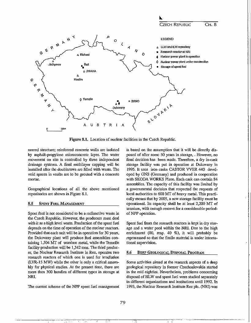
CZECH REPUBLIC CH. 8
N
LEGEND
A LLW and ILW repository
• Research reactor at NRI
| Nuclear power plant in operation
0 Nuclear power plant under construction
• Storage of spent fuel
V
A U S T R I A50km
Figure 8.1. Location of nuclear facilities in the Czech Republic.
neered structure; reinforced concrete walls are isolatedby asphalt-propylene microconcrete layer. The watermovement on site is controlled by three independentdrainage systems. A final multilayer capping will beinstalled after the doublerows are filled with waste. Thevoid spaces in vaults are to be grouted with a concretemortar.
Geographical locations of all the above mentionedrepositories are shown in Figure 8.1.
8.5 SPENT FUEL MANAGEMENT
Spent fuel is not considered to be a radioactive waste inthe Czech Republic. However, the producers must dealwith it as a high level waste. Production of the spent fueldepends on the time of operation of the nuclear reactors.Provided that each unit will be in operation for 30 years,the Dukovany plant will produce fuel assemblies con-taining 1,504 MT of uranium metal, while the Temelfnfacility production will be 1,342 tons. The third produc-er, the Nuclear Research Institute in Rez, operates tworesearch reactors of which one is used for irradiation(LVR-15 MW) while the other is only a critical assem-bly for physical studies. At the present time, there aremore then 300 bundles of different types in storage atNRI.
The current scheme of the NPP spent fuel management
is based on the assumption that it will be directly dis-posed of after some 50 years in storage,. However, nofinal decision has been made. Therefore, a dry in-caskstorage facility was put in operation at Dukovany in1995. It uses iron casks CASTOR W E R 440 devel-oped by GNS (Germany) and produced in cooperationwith SKODA WORKS Plzen. Each cask can contain 84assemblies. The capacity of this facility was limited bya governmental decision that respected the requests oflocal authorities to 600 MT of heavy metal. This practi-cally means that by 2005, a new storage facility must beoperational. Its capacity shall be at least 2,200 MT ofuranium, with enough reserve for a considerable period-of NPP operation.
Spent fuel from the research reactors is kept in dry stor-age and a water pool within the NRI. Due to the highenrichment (80, resp. 40 %), it will probably bereprocessed so that the fissile material is under interna-tional supervision.
8.6 DEEP GEOLOGICAL DISPOSAL PROGRAM
Some activities aimed at the research aspects of a deepgeological repository in former Czechoslovakia startedin the mid eighties. Nevertheless, problems concerningdisposal of HLW and spent fuel were studied separatelyin different organizations and institutions until 1992. In1993, the Nuclear Research Institute Rez pic. (NRI) was
79

CZECH REPUBLIC C H . 8
entitled to coordinate the activities which would lead tothe development of the Czech geological repository.This year, a general geological disposal program wasreleased and successfully reviewed by a WATRP mis-sion (organized by IAEA) with recommendations forfurther direction of the program. Since 1994, theProgram has been supervised by a Steering Committeeof Six Institutions (C6).
The essential technical parts of the deep geological dis-posal program are:
• siting (and related geological activities such as anunderground research laboratory and natural ana-logue study);
• repository design and disposal engineering;• development of engineered barriers;• safety analyses and performance assessment; and• alternative disposal options (transmutation).
QA/QC, program/projects management and integration,program information systems, and external relations areadditional activities of the Program. The Program hasbeen focused mainly on preliminary and generic studiesso far, and it considers hard host rock as a most proba-ble option.
8.6.1 Repository design and disposal engineering
Preliminary conceptual disposal system design includ-ing infrastructure has been worked out. The present ref-erence design considers two access shafts (one for per-sonnel, one for waste), one ventilation shaft and a sys-tem of main and horizontal parallel disposal drifts.Other alternative designs are proposed that differ main-ly in access tunnel design (for example spiral andinclined access to the underground). Particular alterna-tive designs were evaluated preliminarily on the basis ofsafety and feasibility.
An optimization study of spent fuel conditioning priorto disposal indicates a preference for minimum restruc-turisation of fuel assemblies. An encapsulation unit isdesigned as an integral part of the disposal system at thesite. Several repository transport and handling systemoptions have been proposed.
The preferable excavation method for undergroundspaces has not been selected yet; the importance of theextent of disturbed zones is questionable. The problemis analogous to an underground cavern built for storageof gas; this was mined in granitoid host rock more than1000 m below the surface in the Pribram uranium min-
ing region. The alternative use of backfill and sealingmaterials is also studied.
Calculations of radionuclide contents and heat output(ORIGEN code) for spent fuel with different burnupshave been performed. According to preliminary heattransfer calculations an optimal configuration for dis-posal rooms and disposal boreholes was designed.
A cost analysis of the disposal system was also carriedout. The objective was to propose an algorithm fordetermining the waste producers fee for disposal ofradioactive wastes (0.05 CZK/kWh). This study esti-mates an overall disposal system cost of approximately100 billion CZK (i.e. approx. 3.5 billion US$).
8.6.2 Development of engineered barriers
Bentonite (and bentonite-based mixtures) was selectedas a suitable buffer and backfill material. A bentoniteavailability study identified many deposits in the CzechRepublic; the main criteria considered were materialquality and planned volume of buffer and backfill. Apreliminary design of a disposal container was proposedby the main Czech steel product manufactures; alterna-tive materials, such as titanium and stainless steel, werealso considered.
Planning of experiments, such as spent fuel leaching,engineered barriers degradation, corrosion of disposalcontainer, has started. The main objective of theseexperiments is validation of models. Both laboratoryand field experiments are to be used.
8.6.3 Performance assessment
Performance assessment is considered to be of keyimportance in the Program because of the necessity toprove long-term safety of the disposal concept. In a pre-liminary stage, all near-field and far-field features,events and processes (FEPs) have been continually iden-tified, databased and evaluated. Suitability of codesshall also be evaluated. A safety analysis methodologywas studied, including methods of probabilistic safetyanalysis (PSA). In 1995, a study using the Czech formatfor an Environmental Impact Assessment was per-formed.
8.6.4 Alternative disposal options
Transmutation technology has been studied as a com-plementary but not fully replaceable option to the dis-posal of spent fuel. Preferably, accelerator driven sys-
80

CZECH REPUBLIC CH. 8
terns seem to be the most promising. When consideringthe practical aspects, many unsolved problems havebeen identified, such as continual hot chemical separa-tions, complicated physical systems, non-verified tech-nology, unresolved benefits and costs. Although mainlygeneric and system studies were performed, long-termexperience of NRI staff with fluorine chemistry andreactor physics as well as the theoretical background ofthe Nuclear Physics Institute, skills of employees of theSKODA machinery works and promotion of reactordesigners speak for reasonability and good startingpoints for initiation of the respective research and devel-opment experiments. Transmutation is a typical problemrequiring wide international involvement, and thus,Czech specialists are linked with several US, Europeanand Japanese institutions.
8.6.5 Public/external relations
Taking into account the high population density in theCzech Republic and the deep environmental feelingcoming from a damaged natural environment, the strongNIMBY syndrome and general disapproval with the dis-posal concept are expected. As a consequence, the soci-etal and political factors in a deep geological repositoryprogram will be very important.
The communication program is aimed not only toinform the general public but it shall also initiate somedirect public participation in decisions. The communi-cation policy is based on open, full and understandableinformation for the public. Current activities includepublication of a series of informative articles in newspa-pers and magazines, editing of purposeful brochures,preparation of video presentations, presentation of theProgram on the conferences and lecturing at universi-ties. RACE methodology (research, analysis, communi-cation, evaluation) is being applied; the final step is car-ried out in the form of a public opinion poll. Poorknowledge of radioactive waste management rather thandissent from any disposal solution and, surprisingly,general agreement with nuclear power generation arethe main findings of the first public opinion polls.
An inseparable part of external relations is cooperationwith foreign organizations involved in radioactive wastemanagement, such as ANDRA, GRS, AECL, andENRESA.
8.6.6 QA/QC
A quality assurance system is being created along with
the quality and management guides/manuals; especiallyISO 9,000 and 14,000 are taken into account. The sys-tem follows two general directions: QA of the Programmanagement and QA binding technical activities withinperformance of the Program.
8.6.7 Scope of work in 1996
In 1996, the Program activities are focused on the revi-sion of the Deep Geological Disposal Program. Theobjectives are to formulate general as well as detailedprojects and plans based on evaluation of acquired expe-rience and on information gained since the start of theProgram. System re-engineering principles will beexplored; they involve the complex, multidisciplinaryand time/cost consuming character of the problem to besolved. License, technical and system requirements arebeing identified along with critical points of theProgram. The year 2035 is the main time constraint,when the deep geological repository shall be opera-tional.
8.7 GEOLOGICAL ASPECTS OF DEEP GEOLOGICAL
REPOSITORY
8.7.1 Brief Geological History of the CzechMassif
The selection of an optimal geological unit for DGR is,among others, always limited by the geological structureof the territory. Moreover, in the case of the CzechRepublic, this fact is underlined by a small areal extentand by a significantly complicated geological structure.
According to the classical geological Stille's division,the Bohemian Massif, belongs to the Meso - Europe,e.g. the vast zone, which was consolidated in the latePaleozoic period during the Hercynian orogeny. Withinthe European Hercynides, the Bohemian Massif ranksamong the Variscides which create partial branches ofthe Hercynides. The Bohemian Massif, which representsthe easternmost known part of the Variscan branch,forms the absolute majority of the territory of the CzechRepublic. Brunovistulicum, a block consolidated duringthe Cadomian orogeny or even earlier, is situated in theeastern part of the territory of the Czech Republic. In thewest, this block forms the underlying unit of the easternpart of the Bohemian Massif; in the east, it forms theunderlying unit of the West Carpathians, which belongto the Alpine-Carpathian orogenetic belt (Neo - Europe).
The Hercynian history was closed by folding associatedwith emplacement of numerous plutons and extensive
81

CZECH REPUBLIC C H . 8
regional metamorphism. This folding had reworked thewhole region and often obscured the earlier, Cadomianand probably also some Caledonian structural elements.From this point of view, the Bohemian Massif has a tri-partite structure consisting of the following verticalgroups:
• Precambrian (Cadomian) basement;• Crystalline and Paleozoic affected by Hercynian
orogeny; and• Post-Hercynian platform cover.
8.7.2 Basic geological requirements for host rock
The basic requirements for the geological unit thatshould become a host structure for DGR can be definedas follows:
• sufficient area (tens of square km) and thickness (atleast 1000 m) ;
• lithological homogeneity of the unit with minimalhydrothermal alterations and rock veins;
• tectonic fractures and displacement as low as possi-ble;
• no deposits and indications of mineral resources;• permeability as low as possible; and• seismic and geodynamic stability of the region.
8.7.3 Geological units of the Bohemian Massiffrom standpoint of basic requirements forhost rock
Individual geological units can be evaluated from thepoint of view of suitability for DGR siting as follows:
Post-Hercynian platform cover. Post-Hercynian plat-form cover on the territory of the Czech Republic can bedivided according to age into:
• Permo-Carboniferous sediments;• Mesozoic sediments; and• Tertiary sediments.
Permo-Carboniferous sediments occur in the territory ofthe Czech Republic in two different forms. In the north-east part of the Czech Republic, only a basin is situatedwhere the parallel Namurian developed gradually fromthe marine Lower Carboniferous. In other parts of theCzech Republic, there are numerous limnic Permo-Carboniferous sediments placed discordantly upon vari-ous older units. We regard Permo-Carboniferous sedi-ments as unsuitable for DGR because of their litholog-
ical variety and relatively extensive tectonic displace-ment.
The absolute majority of Mesozoic sediments in the ter-ritory of the Czech Republic are of Upper Cretaceousage. Continental sediments of Lower Triassic and epi-continental sediments of Upper Jurassic have no signif-icance because of their small range. Lacustrine sedi-ments of the Upper Cretaceous are known in the south-ern part of the Czech Republic, where they filled twoseparate basins. As far as their lithological nature is con-cerned, they are composed of sandstones, siltstones andclaystones with rapid vertical as well as horizontalchanges. In the north of the Czech Republic theBohemian Cretaceous Basin is widespread. Its area isapproximately 14,000 km2. The largest supply of highquality drinking water in the Czech Republic is found insandstones. Mesozoic sediments are regarded as unsuit-able for DGR because of their lithological nature.
The majority of Tertiary sediments is mostly of lacus-trine origin. They occur, on the one hand, in the north-west of the Czech Republic (accompanied by alkalinevolcanism of Tertiary and Quaternary age), where theyform the filling of the vast, tectonically predisposed,system of basins, and, on the other hand, in the south ofthe Czech Republic, forming the overlying beds ofUpper Cretaceous sediments. As far as their lithology isconcerned, they are characterized by rapid horizontal, aswell as vertical, changing of clays and sands. In thenorthwest there are important and intensively exploitedlignite seams, which are part of these sediments.
As far as the DGR is concerned, the Tertiary sedimentsdo not have desirable features, especially because oftheir lithological variety and significant tectonic frac-tures.
Crystalline and Paleozoic affected by Hercynianorogeny. This group includes metamorphosed pre-Cambrian and Paleozoic rocks and non-metamorphosedrocks of Lower Paleozoic (Cambrian to MiddleDevonian). Cadomian and Hercynian plutonic rocks arenumerous.
Non-metamorphosed Cambrian to Middle Devonianformations occur in several separated basins. The for-mations in question are predominantly shales, siltstones,carbonates, sandstones and conglomerates, oftenaccompanied by volcanism. In our opinion these for-mations are not suitable for DGR siting, because of theirintensive folding, tectonic displacement and in view of
82

CZECH REPUBLIC C H . 8
G
LEGEND
k%»***| Granitoidbodies
j \ * » * v * | Gabbrobbody
• Candidate areas
Tea site
Figure 8.2. Location of candidate areas and test site in the Czech Republic.
varied lithological composition and karstification oflimestones.
Units of metamorphosed rocks prevail in this group.Elements of Cadomian metamorphism appear in most ofthese units. According to geological and geochronolog-ical data, the Cadomian metamorphic activity can beobserved from 650 to 550 Ma. Presence and role of theCaledonian metamorphism is still discussed by experts.The Hercynian regional metamorphism is most signifi-cant in the territory of the Bohemian Massif. This meta-morphism started in the Ordovician, culminated in theUpper Devonian and ended in the Carboniferous.
In view of the very complicated tectonic structure, oftenand rapidly changing intensity of metamorphosis andlithological variety of metamorphosed units, wheremoreover numerous intercalations of crystalline lime-stones, graphite layers or quartz veins occur, we do notregard the metamorphosed units as suitable host rocksforDGR.
The occurrence of extensive plutonism is a characteris-tic feature of the above mentioned group (Fig. 8.2). Thefollowing plutonic complexes have been distinguished:
• metaplutonites of uncertain age, which occur pre-dominantly in the form of orthogenesis in marginal
parts of the Bohemian Massif;• plutonites associated with Cadomian orogeny, which
form several granitoid and gabbroid bodies in thewest and north parts of the Czech Republic; and
• plutonites associated with Hercynian orogeny, whichare the most frequent on the territory of theBohemian Massif.
The Hercynian plutonites are exclusively granitoids.The two largest bodies - the Moldanubian Pluton witharea of 8,000 square km approximately, and the CentralBohemian Pluton with the area of 3,200 square kmapproximately, as well as many smaller bodies belongamong them. According to geochronological data, theage of the majority of the above mentioned granitoids isbetween 350 - 300 Ma, and their development is con-nected to the late tectonic phase of Hercynian metamor-phic stage.
We consider granitoid bodies connected with theCadomian as well as Hercynian orogeny as suitable forDGR.
Precambrian (Cadomian) basement. Precambrianbasement untouched by the earlier Hercynian orogenyoccurs in the territory of the Czech Republic just inBrunovistulicum. This unit as a whole is not suitable forDGR location especially because of its significant geo-
83

CZECH REPUBLIC C H . 8
logical variety.
8.7.4 Description of General Project Objectives
The present state of activities on DGR siting in theCzech Republic results from work which was performedduring the last 5 years. An area selection of 27 suitableregions was performed on the basis of existing regionalgeological information by the Czech Geological Survey.
The siting process continues with the approval of theGeneral Project of Geological Activities for DeepGeological Repository Siting , which was elaborated byNRI staff. The project cut the number of potential areasfrom 27 to 13. From this number, 12 areas are located ingranitoid bodies and one in an ultrabasic body. The areaof relevant sites ranges from 120 to 20 square km.
The General Project became a principal document, uponwhich all geological activities concerning developmentof the deep geological repository are performed.Principal geological activities are planned in accor-dance with the General Project for approximately thefollowing 15 years. It is assumed that the deep geologi-cal repository will be put into operation in 2035.
The activities described in the project are divided intothe following stages:
• research activities;• seismicity, geodynamics and neotectonic monitoring;• critical evaluation of pre-existing geological infor-
mation;• site characterization ; and• site confirmation.
The project does not deal in details, neither with anunderground laboratory nor natural analogues. Theseactivities are supposed to be solved by independent pro-jects, whose time schedule and logical structure will beco-ordinated with the General Project, especially withthe stage of research activities.
Stage of research activities. The main task of this stageis development, practical verification and elaboration ofobligatory methodological procedures relevant to thedeep geological repository siting. These activities willbe performed at the test site selected in geological con-ditions similar to those, where the construction of therepository is proposed. The site in question isMoldanubian Pluton apophyse. DGR will not be built atthe testing site, but we will consider the siting of anunderground laboratory there. Currently, characteriza-
tion of the site is being performed. The project ofresearch activities will be completed in 1997, and theactivities are supposed to start in the same year.
Stage of seismicity, geodynamics and neotectonicsmonitoring. In view of the above mentioned geologicalstructure of the Bohemian Massif and its incorporationin the European Hercynides, no significant motions canbe expected, but on the other hand insignificant motionscannot be excluded with sufficient certainty. Howeverinsignificant the motions might be, they could negative-ly influence the DGR safety. That is why we pay thenecessary attention to monitoring the stability of the rel-evant part of the Bohemian Massif.
These activities will be started at the end of 1996 or inthe beginning of 1997. In a preparatory phase, all avail-able information on hardware and software concerningscanning data and their transmission to the processingcenter as well as their processing and evaluation will begathered. Simultaneously, selection of suitable posts forseismometers, determination of sites suitable for neotec-tonic studies, densification of the network of existingobserving points will be realized. The remote sensingevaluation will also be realized within this stage.
Stages of critical evaluation of pre-existing geologicalinformation, site characterization and site confirma-tion. These stages represented activities, which willresult in selection of the optimal site for DGR in the ter-ritory of the Czech Republic. The activities began in1995 and at present, a critical evaluation of availablegeological information is in progress. Starts of the nexttwo stages are scheduled for 1998 and 2003. Contents ofthe single above mentioned stages are as follows:
The stage of critical evaluation of pre-existing geolog-ical information includes collecting of geological datafrom archives. The principal evaluating criterion is thenature and quality of each information and its utilizationfor siting. The data being evaluated concern geology,geophysics, hydrogeology, hydrology, climatology, geo-chemistry, seismology, but also demography, environ-mental protection and the most significant conflicts ofinterests. Approximately 7 sites are supposed to beselected from existing 13 at the end of this stage andrecommended for the next stages.
Within the site characterization stage, a non-destruc-tive (not disturbing rocks in the depth, where DGRmight be situated) geological survey will be performedat all sites. This stage will include:
84

CZECH REPUBLIC CH. 8
• geological mapping at a scale of 1 : 10,000 and struc-tural geology studies;
• aerial and surface geophysics, especially gravitymeasurement, magnetometry, geoelectric methods,logging measurements in all bore holes and othernecessary methods;
• boring works down to a depth of 200 - 300 m;• detailed petrologic and mineralogic studies;• geochemical mapping;• hydrological and hydrogeological characterization of
the site; and• engineering-geological mapping and geotechnical
characterization of the site.
These activities are supposed to be performed on siteswith an area of 10 - 50 square km each. In addition, thegranitoid body surrounding metamorphosed complexeswill be examined to the necessary extent in justifiedcases.
A detailed descriptive characterization of the whole ter-ritory will result from this phase. On the basis of thischaracterization, a final decision on the suitability of theexamined site, or its part for DGR siting, will be made.This stage results in a selection of two or three sites forfurther investigation.
The site confirmation stage. Destructive phase of activ-ities will be started in one of the candidate sites, the oth-ers will serve as spare ones. Boring and special geo-physical methods will be used predominantly in thisstage. According to the assumptions of the GeneralProject, the details of the verified site for DGR con-struction in the Czech Republic should be known by2010.
8.8 CONCLUSIONS
Disposal of radioactive wastes has been practiced in theCzech Republic for more than 40 years. Different geo-logic environments were selected as host rocks forthose subsurface facilities. This experience allows us tocarry out successful research and development of a deepgeological repository able to accept both decommis-sioning long lived and/or high level wastes and spentfuel from nuclear reactors. When considering the avail-able geological systems and its variability in the CzechRepublic, hard rocks, namely granitoid bodies, seem to
be the most hopeful rocks for construction of a deepgeological repository. The relevant national programwas initiated in the early nineties aimed at developmentof this underground facility.
Technical abilities, however, are not fully supported byexisting legal tools and the organizational system.Parallel management of radioactive wastes arising fromdifferent sources will probably survive till the newlyprepared Atomic Law passes through the Czech parlia-ment. In dealing with radioactive waste management,the governmental proposal contains several new princi-ples, namely:
• state guarantees safe disposal of radioactive wastes,although the waste generators must bear the respec-tive costs;
• import of radioactive wastes for their disposal on theCzech territory is forbidden;
• Nuclear Account, established out of the state budget,collects fees from waste producers to ascertainenough financial sources for final disposal of allradioactive wastes; the Account is controlled by acommittee consisting of representatives of waste pro-ducers, state institutions and public; and it is underthe supervision of the Ministry of Finance;
• new Office of Repository Management is created; itprovides disposal services in existing facilities and isresponsible for research and development in thisfield, including development of a deep geologicalrepository; and
• a position of the State Office for Nuclear Safety as anindependent supervisor in nuclear and radiologicalissues is stressed.
The Atomic Law shall be completed with a set of near-ly 20 decrees providing the concrete regulations forusers of radionuclides.
Even if the existing legislation is updated, siting ofnuclear facilities, such as storage and disposal facilities,will have to face the high population density in theCzech Republic (130 inhabitants per square km) and allthe negative consequences that this fact may imply.Nevertheless, it is believed that all kinds of radioactivewastes and spent nuclear fuel will be safely conditionedand disposed of in the Czech Republic.
85

86
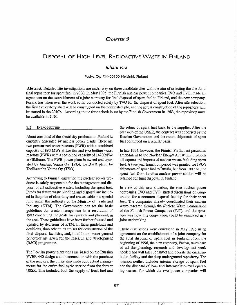
CHAPTER 9
DISPOSAL OF HIGH-LEVEL RADIOACTIVE WASTE IN FINLAND
Juhani Vira
Posiva Oy, FIN-00100 Helsinki, Finland
Abstract. Detailed site investigations are under way on three candidate sites with the aim of selecting the site for afinal repository for spent fuel in 2000. In May 1995, the Finnish nuclear power companies, IVO and TVO, made anagreement on the establishment of a joint company for final disposal of spent fuel in Finland, and the new company,Posiva, has taken over the work so far conducted solely by TVO for the disposal of spent fuel. After site selection,the first exploratory shaft will be constructed on the nominated site, and the actual construction of the repository willbe started in the 2010's. According to the time schedule set by the Finnish Government in 1983, the repository mustbe available in 2020.
9.1 INTRODUCTION
About one third of the electricity produced in Finland iscurrently generated by nuclear power plants. There aretwo pressurized water reactors (PWR) with a combinedcapacity of 890 MWe at Loviisa and two boiling waterreactors (BWR) with a combined capacity of 1420 MWeat Olkiluoto. The PWR power plant is owned and oper-ated by Imatran Voima Oy (IVO), the BWR plant, byTeollisuuden Voima Oy (TVO).
According to Finnish legislation the nuclear power pro-ducer is solely responsible for the management and dis-posal of all radioactive wastes, including the spent fuel.Funds for future waste handling and disposal are includ-ed in the price of electricity and are set aside in a specialfund under the authority of the Ministry of Trade andIndustry (KTM). The Government has set the basicguidelines for waste management in a resolution of1983 concerning the goals for research and planning inthe area. These guidelines have been further focused andupdated by decisions of KTM. In these guidelines anddecisions, time schedules are set for construction of thefinal disposal facilities, and, in addition, some generalprinciples are given for the research and development(R&D) programme.
The Loviisa power plant units are based on the RussianVVER-440 design and, in connection with the purchaseof the reactors, the utility also made contractual arrange-ments for the entire fuel cycle service from the formerUSSR. This included both the supply of fresh fuel and
the return of spent fuel back to the supplier. After thebreak-up of the USSR, the contract was endorsed by theRussian Government and the return shipments of spentfuel continued on a regular basis.
In late 1994, however, the Finnish Parliament passed anamendment to the Nuclear Energy Act which prohibitsall exports and imports of nuclear waste, including spentfuel. A two-year transition period was granted for IVO'sshipments of spent fuel to Russia, but from 1997 on, thespent fuel from Loviisa nuclear power station will beretained for final disposal in Finland.
In view of this new situation, the two nuclear powercompanies, IVO and TVO, started discussions on coop-eration for a common disposal facility for their spentfuel. The companies already coordinated their nuclearwaste research through the Nuclear Waste Commissionof the Finnish Power Companies (YJT), and the ques-tion was how this cooperation could be enhanced in ajoint undertaking.
These discussions were concluded in May 1995 in anagreement on the establishment of a joint company forthe final disposal of spent fuel in Finland. From thebeginning of 1996, the new company, Posiva, takes careof all the planning, research and development workneeded and will later construct and operate the encapsu-lation facility and the deep underground repository. Themission neither includes interim storage of spent fuelnor the disposal of low- and intermediate-level operat-ing wastes, for which the two power companies will
87
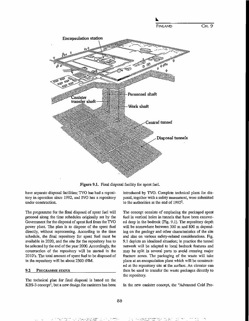
FINLAND CH. 9
Encapsulation station
Personnel shaft
Work shaft
Disposal tunnels
Figure 9.1. Final disposal facility for spent fuel.
have separate disposal facilities; TVO has had a reposi-tory in operation since 1992, and IVO has a repositoryunder construction.
The programme for the final disposal of spent fuel willproceed along the time schedules originally set by theGovernment for the disposal of spent fuel from the TVOpower plant. The plan is to dispose of the spent fueldirectly, without reprocessing. According to the timeschedule, the final repository for spent fuel must beavailable in 2020, and the site for the repository has tobe selected by the end of the year 2000. Accordingly, theconstruction of the repository will be started in the2010's. The total amount of spent fuel to be disposed ofin the repository will be about 2500 tHM.
9.2 PROGRAMME STATUS
The technical plan for final disposal is based on theKBS-3 concept1, but a new design for canisters has been
introduced by TVO. Complete technical plans for dis-posal, together with a safety assessment, were submittedto the authorities at the end of 19922.
The concept consists of emplacing the packaged spentfuel in vertical holes in tunnels that have been excavat-ed deep in the bedrock (Fig. 9.1). The repository depthwill be somewhere between 300 m and 800 m depend-ing on the geology and other characteristics of the siteand also on various safety-related considerations. Fig.9.1 depicts an idealized situation; in practice the tunnelnetwork will be adapted to local bedrock features andmay be split in several parts to avoid crossing majorfracture zones. The packaging of the waste will takeplace at an encapsulation plant which will be construct-ed at the repository site at the surface. An elevator canthen be used to transfer the waste packages directly tothe repository.
In the new canister concept, the "Advanced Cold Pro-
88

FINLAND C H . 9
Figure 9.2. Advanced cold process (ACP) canister for direct disposal of spent fuel.
cess" (ACP) canister is a composite canister consistingof an inner container of steel as a load-bearing elementand an outer container of oxygen-free copper to providea shield against corrosion (Fig. 9.2). The wall thickness-es are 60 mm for the copper canister and 55 mm for thesteel canister. The original canister design was only for9 BWR fuel assemblies from the TVO power plant, butit has been modified for the hexagonal fuel elementsfrom the Loviisa PWRs assemblies as well. The emptyspace in the canister can be filled with a granular mate-rial, such as lead shot, glass beads or quartz sand, butother alternatives are also being considered. Dependingon the filling material used, the total weight of the fullcanister will be 14 to 20 tonnes.
The name of the canister design (Advanced ColdProcess Canister) is due to the principal driving forcebehind the development work. The original KBS coppercanister design assumes a lead casting to fill the voidsbetween the fuel assemblies and canister walls. Since
the lead casting would probably be the technically mostdifficult phase in the encapsulation process, the questionwas raised whether the use of molten lead could beavoided by replacing it with some "cold" material.However, the copper canister without the cast lead mightnot meet the mechanical requirements, mainly becauseof the creep properties of copper. In the ACP canister,the use of molten lead has been avoided because themechanical strength is now provided by the inner steelcanister.
For the selection of the repository site, the strategy is tofind a "good enough" site, i.e., a site that offers suffi-cient characteristics to ensure the long-term safety ofdisposal. It is considered both unnecessary and unrealis-tic to try searching for the "best" site.
The site selection process for a repository started in1983 with a country-wide survey of the principal geo-logical features in Finland. The approach used for local-
89
FINLAND C H . 9
Repository area0.4 x 0.7 km
Investigation area
Figure 9.3. Principle site selection for the spent fuel repository.
ization of candidate sites was based on the crush-tecton-ic block structure of the Finnish bedrock. All thebedrock in Finland is broken down into blocks separat-ed by regional crush (or shear) zones whose length maybe dozens of kilometres (Fig. 9.3). These, in turn, aredivided into smaller sectors according to the presence ofsmaller fracture zones. What is important for repositorysiting is that the rock response to future changes in stressconditions be mainly confined to these crush zones,while the rock outside the fracture zones remains basi-cally unaffected. This will ensure sufficient stability forthe host rock of the repository.
A total of 327 large regional blocks were identified inthe first country-wide screening of the bedrock features.Mainly for land-use restrictions and other geographicreasons, the number of possible regions was laterreduced to 61, among which 134 smaller areas wereselected as candidates for investigation sites. In 1987,
five areas were selected for preliminary site investiga-tions. These are situated in different parts of the countryand represent somewhat different geologic histories(Fig. 9.4). In addition to geologic factors, geographicfactors, land ownership and transport and other infra-structure considerations were taken into account in theselection of the sites for preliminary site investigations.One of the areas chosen for investigations is theOlkiluoto island in Eurajoki where the TVO power plantis also situated.
The principal goal of the preliminary site investigationswas to characterise the candidate sites to the extentneeded to judge whether the preconception on their suit-ability for hosting a repository could be confirmed. Theinvestigations at each site comprised drillings and sam-plings, various geophysical, geohydraulic, rock-mechanical, chemical and mineralogical studies, andmodelling of the bedrock structure and groundwater
9 0
•- "'"•• P

FINLAND C H . 9
Figure 9.4. Preliminary site investigations areas in 1987-1992. Kuhmo, Konginkangas (since 1993 a part ofAanekoski town) and Eurajoki were selected in 1992 for detailed site investigations.
flow in the area. At least five deep (500 to 1000 m) coredboreholes were drilled in addition to a number of shal-low boreholes. The results of the preliminary site inves-tigations were submitted to the authorities at the end of19923. These results did not reveal any surprises in rela-tion to expectations; no exceptional features weredetected that would compromise the siting of the repos-itory within the area studied.
In parallel with these site investigations, a safety assess-ment ("TVO-92") was carried out4. The analysis usedthe data from the preliminary site investigations but wasnot specific as to any of the sites studied. The principlehas been to select the parameters and assumptions insuch a way that a location could be found at each of thesites with certainly more favourable conditions thanwere assumed in the safety assessment. For example,very conservative assumptions were made with regard togroundwater flow at the repository site. It was assumed
in the reference scenario of the analysis that the ground-water transit time from the repository to the biosphere isonly five years.
The safety analysis includes a detailed groundwaterflow analysis for a hypothetical repository located at oneof the investigation sites. Figure 9.5 depicts how therepository could be adapted to the local fracture zonesaround the deep drillholes. It is seen that two fracturezones, R l l and R15, cross the repository area. If thetransmissivity of the repository (together with the exca-vation damage zones) were high in relation to the sur-rounding rock, then in principle, a U-tube flow condi-tion could form. Although, in reality, this would be veryunlikely, such a situation has been taken as the basis inthe reference scenario of the safety assessment.
The number of scenarios was kept small by restrictingthe analysis to a set of bounding cases that, nevertheless,
91

FINLAND C H . 9
AREA AVAILABLE FOR REPOSITORY TUNNELS500 m
Figure 9.5. Adaptation of the repository to local bedrock features (example from Hyrynsalmi investigation site).
cover all reasonably conceivable situations. Aside fromthe base case (the conditions in the vicinity of the repos-itory remain basically as they are now), the analysis hasbeen centred on the reference case, which simplyassumes a total loss of canisters after 10,000 years fromthe time of deposition. This simplification has helped togreatly reduce the number of different scenarios in theanalysis.
Despite the conservative data and concepts adopted, thesafety analysis shows that the criteria proposed by theNordic safety authorities in 1993 can easily be met5. Atthe same time, the analysis shows that safety is ensuredno matter which one of the candidate sites is chosen.
In addition to geology and long-term safety, variousother aspects of the candidate sites were assessed, suchas local infrastructure and available means and routes oftransportation and constructability. It turned out that
there were no decisive differences between the sitesstudied. However, for focusing the field work further,the decision was made to restrict the detailed investiga-tions to three candidate sites: Eurajoki, Kuhmo andAanekoski (formerly Konginkangas). The choice wasmainly based on the practicality of investigations; itwas evident that at the two discarded sites (Sievi,Hyrynsalmi), investigations would have to be extendedover a larger area than was well covered by the drillingsduring the preliminary site investigations. At the threeselected sites, the future investigations could most effi-ciently make use of the already existing boreholes andother data.
9.3 FUTURE INVESTIGATIONS
Detailed site investigations are now under way on thethree candidate sites with the objective of establishingthe database needed for site selection in the year 2000.
92

FINLAND C H . 9
In 1994, TVO also conducted a prefeasibility study inKannonkoski, a neighbouring municipality to Aanekos-ki, as a possible site for the repository. On the basis of ageologic survey and other considerations, it was con-cluded that Kannonkoski could be an alternative toAanekoski, in case there was need to search for newcandidate sites; but for the moment, the three candidatesites are considered sufficient. Now, after the decisionby IVO and TVO to work toward a joint repository, asimilar prefeasibility study is being conducted atLoviisa, the site of the IVO power plant. The need fordrilling and other field work at Kannonkoski or Loviisawill be considered at the end of 1996, when an .interimreport of all studies and investigations conducted since1992 will be submitted to authorities.
For site selection, a site-specific safety analysis will becarried out for the nominated site and the technical con-cept by the end of 2000. Updated technical plans will bepresented, including preliminary layouts adapted to thelocal geologic features. Later, in the early 2000's thefirst exploratory shaft will be constructed at the site, andthe construction work for the repository itself can bestarted after 2010, assuming a favorable developmentwith the licensing.
For drilling and other surface-based site investigations,the only license required so far is permission from theland-owner, who, in the case of the candidate sites, isthe state or the power companies themselves. However,construction of the repository is possible only after apositive decision by the Parliament, and such decisioncan only be made if the local municipality approves thesiting proposal. Since the local veto cannot be overrid-
den, public acceptance will be crucial for the successfulimplementation of the plans. According to the presenttime schedule, the municipality will have to define itsposition on the proposed siting in about ten years. Togain local support for the plan will be a major challengein providing for the ultimate disposal of nuclear wastesin Finland.
REFERENCES
1. Final storage of spent nuclear fuel, KBS-3, SwedishNuclear Fuel Supply Co., 1983.
2. Final disposal of spent fuel in the Finnish bedrock:technical plans and safety assessment, TeollisuudenVoima Oy. Nuclear Waste Commission of FinnishPower Companies, Report YJT-92-31E, Helsinki,1992.
3. Final disposal of spent fuel in the Finnish bedrock:preliminary site investigations, Teollisuuden VoimaOy. Nuclear Waste Commission of Finnish PowerCompanies, Report YJT-92-32E, Helsinki, 1992.
4. Vieno, T., A. Hautojarvi, L. Koskinen, and H.Nordman, TVO-92 safety analysis of spent fuel dis-posal, Nuclear Waste Commission of Finnish PowerCompanies, Report YJT-92-33E, Helsinki, 1992.
5. Disposal of high level radioactive waste:Consideration of some basic criteria, The RadiationProtection and Nuclear Safety Authorities inDenmark, Finland, Iceland, Norway and Sweden,1993.
93
9 4

CHAPTER 10
STATUS OF RESEARCH O N GEOLOGICAL DISPOSAL FOR HIGH LEVEL
RADIOACTIVE WASTE IN FRANCE
Michel Raynal*
Agence Nationale pour la Gestion des Dechets Radioactifs92266 Fontenay-aux-Roses Cedex, France
10.1 INTRODUCTION
Research programs in the field of high-level, long-livedradioactive waste management are defined and regulat-ed by Law 91-1381 of December 30, 1991 ("the WasteAct") and its implementing decrees, particularly Decree92-1391 of December 30, 1992 pertaining to Andra andDecree 93-940 of July 16,1993 on underground labora-tories.
The Waste Act relative to research on radioactive wastemanagement mandates three research programs on high-level and long-lived waste management:
• separation and transmutation of long-lived radioac-tive elements;
• solidification processes and long-term surface stor-age; and
• examination of options for retrievable and non-retrievable disposal in deep geologic formations.par-ticularly through the construction of undergroundlaboratories.
The first two programs are relegated to the FrenchAtomic Energy Commission (CEA) and will be con-ducted in the latter's laboratories. The Act confersresponsibility for the third research program on Andra.In this capacity, Andra is charged with conducting a pro-gram of research and testing to examine the potential forconstruction of a retrievable or non-retrievable reposito-ry in deep geologic formations. Andra is also called onto participate in the other two research programs in asso-ciation with the CEA.
Article 13 of the Waste Act charges Andra with long-term management of radioactive waste and "to partic-
pate in defining and conducting research and develop-ment programs on long-term radioactive waste manage-ment, in association with the French Atomic EnergyCommission in particular."
Annual progress reports on the three research programsare required (Article 4), as is an overall assessmentreport, "no later than 15 years after the promulgation ofthis law, accompanied by proposed legislation authoriz-ing the creation of a repository for long-lived radioac-tive waste, as appropriate and establishing the condi-tions for essential and seats relating to this repository"
These reports, to be prepared by the NationalAssessment Commission, are to be submitted by thegovernment to Parliament, which refers them to theParliamentary Office of Science and TechnologyAssessment. All reports will be made public.
The decree of December 30, 1992 relative to Andraadditionally stipulates that the latter shall provide thefollowing to its oversight ministries:
• an annual report on work performed to date or to beperformed in the underground laboratories to deter-mine the suitability of deep geologic formations forradioactive waste disposal; and
• a summary report on all findings no later thanDecember 31, 2005, accompanied as appropriate bya design for an underground repository for high-leveland long-lived radioactive waste.
This Technical Activity Report by Andra reviews studiesperformed to date and serves as a baseline for Andraresearch programs to be conducted over the coming
*Currently with International Atomic Energy Agency in Vienna.
95

FRANCE CH. 10
years.
10.2 WHAT IS A DEEP GEOLOGIC REPOSITORY?
The purpose of geologic disposal is to contain radioac-tivity with a system of devices and measures that pre-vents radioactive materials transport to the biosphere, orat least limits it to a specified level.
Containment is based on the concept that a series of nat-ural and artificial barriers can be placed between thesource term, i.e., the waste itself, and the biosphere, list-ed below:
• the waste package (waste, solidification material,container and possibly overpack);
• the engineered barrier (repository structures andbackfill material around the waste packages); and
• the geologic barrier (natural geologic media andaccess closure system).
The geologic medium plays a dual role in this scheme ofthings. It provides protection with respect to the sourceterm and it protects the biosphere:
• by protecting the artificial barriers from human intru-sion and the effects of weather;
• by providing a physical and chemical environmentfor the artificial barriers that is stable over longperiods of geologic time; and
• by helping to retard and restrict radionuclide trans-port to the biosphere (retention, dilution beforereaching the biosphere).
The three barriers in the containment system reinforceeach other, with the geologic barrier playing a criticalrole in long-term containment. The overall integrity ofthe three-barrier system must be demonstrated.
Reference conditions for the multi-barrier system mustbe taken into consideration in two areas:
• the waste, expressed in terms of radioactive content,physical characteristics and solidification materials;and
• the geologic medium, represented by the formationand its surrounding geologic environment.
10.2.1 Waste
Generators have been generating and storing long-livedwaste for several decades pending the availability of a
geologic repository. Most of this waste has already beensolidified in a variety of materials in accordance withregulatory requirements: glass for fission products fromreprocessing, and concrete or bitumen for dry activewaste. Although Andra played only a small part in thepreliminary selection of materials for this type of wastein the past, henceforth it will have a larger role, asspelled out in Article 13 of the law- "Andra is chargedwith defining, in accordance with safety regulations,radioactive waste solidification and disposal specifica-tions." Andra could, therefore, require the use of addi-tional solidification materials, for example, even forwaste that has already been solidified waste, or couldchange the cooling requirements for exothermic waste.
For purposes of long-term management, radioactivewaste is differentiated by type, by activity level and bythe half-life of the contaminating radionuclides it con-tains, based on the duration of their potential hazardous-ness.
Low- and medium-level, short-lived waste, calledCategory A waste, contains primarily beta- and gamma-emitting radioelements whose radioactive half-lives areapproximately thirty years or less (such as cesium 137,cobalt 60, strontium 90, etc.). This waste, generated byroutine nuclear facility operations, represents approxi-mately 90% of the total volume of radioactive wastegenerated annually in France, but accounts for only 1%of its total activity. The radioactivity of this type ofwaste decays to natural levels in less than 300 years dueto the relatively rapid decay rate of the radionuclides itcontains, and it may, therefore, be suitable for near-sur-face monitored disposal during this time frame.
The other type of waste, which is long-lived waste andhigh-level waste, is divided into two categories, each ofwhich includes long-lived waste:
• low- and medium-level Category B waste containssignificant amounts of long-lived radionuclides,especially alpha-emitting transuranics;
• Category C waste contains high concentrations ofboth short- or medium-lived fission products andlong-lived, alpha emitting transuranics.
Category C waste is highly radioactive and heat-emit-ting in the beginning, primarily because of its fissionproduct contents, but this quickly declines due to therapid decay rate of these short-lived elements. In theend, Category C waste will contain mostly long-livedelements, and represents the same types of hazards asso-
9 6

FRANCE CH. 10
ciated with Category B waste. For the most part,Categories B and C waste come from spent power reac-tor fuel reprocessing and from civilian and defenseresearch and production sites of the CEA. Category Bwaste will also be generated during nuclear facility dis-mantling and must be included in waste volume esti-mates for disposal.
The waste volumes to be generated in the comingdecades are not yet finalized due to several uncertain-ties, particularly:
• the amount of fuel to be used in power generation,fuel burnups, and the back-end option selected(reprocessing or direct disposal);
• potential technical advances in reprocessing, particu-larly in the types and volumes of waste generated;and
• method selected to solidify existing waste,
Taking a simplistic scenario — light water fuel repro-cessing of 1100 metric tons of initial uranium metal peryear at a burnup of 33,000 MWd/t beginning in the year2000 — the total volume of solidified waste through theyear 2020 can be estimated at 100,000 m3 for CategoryB waste and 6400 m3 for Category C waste.
Data from tests conducted as part of the other tworesearch programs mandated by law could result inmajor technical shifts in solidification processes affect-ing the types and volumes of waste generated by repro-cessing in addition to their solidification. Conversely, asdata becomes available at the underground laboratorysites, Andra may identify new priorities in the other tworesearch programs. For example, a hierarchy of radionu-clides may be established in light of the retention prop-erties of the multi-barrier system, which could establishseparation and transmutation priorities for certainradionuclides. Or, Andra may develop preliminary spec-ifications for solidification materials based on disposalconditions in deep geologic formations.
All aspects of the final waste packages must be careful-ly characterized to facilitate geologic repository design,Characterization must not be limited to waste volumesor to the physical, chemical and radioactive characteris-tics of waste packages that have been or will be fabri-cated; they should also include long-term behavior, fail-ure probabilities, and then- interaction with other barri-ers. In the case of exothermic waste, duration of storageis an essential parameter for repository design insofar asit is a factor in the waste's temperature; Andra's calcula-
tions must therefore include the date that the spent fuelthat produced the exothermic waste was dischargedfrom the reactor.
Studies of the long-term behavior of waste packageswill make it possible to assess containment capacity —and possibly to find ways of improving containment —and to make sure that the waste packages are compatiblewith the repository concept (receiving capacity, engi-neered barriers ' handling, retrievability, etc.). This willresult in waste package specifications that integrate bothsafety-related requirements and mechanical and physi-cal requirements for waste package handling and dis-posal.
10.2.2 Geologic Barrier
Why dispose of radioactive waste in a deep geologicmedium?
Surface disposal was rejected because the service life ofany repository structures that could be built is muchshorter than the half-lives of long-lived radionuclides.Moreover, it would merely postpone the problems ofrepository monitoring and maintenance to the future,with all the risks that that implies in the deliberatelyconservative scenario in which future civilizations arepresumed to have neither the material means nor thetechnical capability to manage these problems.
Since the goal is to contain radionuclides for long peri-ods of time, a medium with suitable radionuclide con-tainment characteristics that evolves slowly is sought.Deep geologic formations may meet both of these crite-ria. There are vast areas of deep rock suitable for con-taining radioactive products for long periods of time.
At first glance, the low permeability and retentioncapacity of some of these rocks make them suitable forcontaining radioactive products. Enormous areas areavailable at depths of 200 to 1000 meters, a range thatprovides enough protection from surface intrusions yetdoes not compromise the technical feasibility of reposi-tory construction.
These available areas thus constitute physical barriers asmuch for the radioactive waste as for intrusions. Theyare also chemical barriers: water seeping through themis "buffered," acquiring geochemical properties that usu-ally are not very corrosive through interaction with therocks. This phenomenon is what explains how uraniumdeposits could subsist for hundreds of millions of years,
9 7

FRANCE CH. 10
for example. It also explains why the fossil reactors dis-covered in the Oklo uranium deposit in Gabon are anextraordinary illustration of the influence of the geolog-ic medium in the repository scenario; fission productsproduced during "operation" of these natural reactorshave remained trapped in place, contained and protectedfor nearly 2 billion years in an envelope of clay.
In addition, inasmuch as the excavated rock volume fora geologic repository will be a small percentage of thehost rock volume (around 1%), the repository should notsignificantly modify the overall containment capabilitiesof the host rock, especially since the volume of waste tobe disposed of will be even lower (around 1/10%).
Geologic evolution is slow enough to ensure contain-ment integrity for the time necessary for the waste toundergo radioactive decay, as long as certain areas areavoided, such as those with recent volcanic activity orstrong tectonic activity. Potential geologic events arelimited to those that are possible in the geodynamic con-text of the area under considerations for example, thecreation of a mountain chain during the time scales con-sidered (around one hundred thousand years) is notplausible in a stable area such as the Parisian Basin.
To illustrate the slowness of geologic phenomena, onecould also take the example of an area with a great dealof tectonic activity, such as the Messine and Calabreregions, which have risen by 1,500 to 2,000 meters in 5million years at a geologically rapid average rate of 0.4mm/yr.. For a stable area such as the Parisian Basin, theaverage estimated rates are 20 times lower, discountingthe appearance of significant new discontinuities (faultfractures, etc.) in the reference time scale.
In recognizing the potential for disposal in deep geolog-ic formations, can one therefore consider that all geo-logic media are valid? A consensus was quickly reachedamong international experts on three suitable media:granite, salt and clay. In France, the Second CastaingCommission (1984) had this to say about rejecting cer-tain formations: "A number of formations, known to bepermeable, were rejected outright (sand, sandstone,limestone, basalt, etc'.'). However, the Commissionindicated its support for an extension of the initial selec-tion list: "In the first phase, three types of formationswere selected at the European level -granite, salt andclay -perhaps without adequately emphasizing the vari-ety of rocks that enter into these categories. The groupconsiders that the list of rocks resulting from clay evolu-tion (such as shale) or even their more highly metamor-phosed forms (schist and some gneiss), which are wide-
spread rocks, should not be rejected outright"
Nonetheless, the fundamental role of the site itself wasnot forgotten in this expanded list: "It is both a series ofdiverse formations and the interfaces between them thatmake a site attractive; the same formation at anothersite could be determined to be completely unsuitable'.'The Commission came to this conclusion: "Potentialvariation in the properties of the formations, ranked bycategory, are so great that research must focus on spe-cific rocks and sites as soon as preliminary screening iscompleted."
However, even the cited media have different theoreticaladvantages and disadvantages for disposal. In addition,one medium may be more suitable than another forexothermic waste disposal. Lastly, the geologic barrierwill have to be reestablished by backfilling and closingthe access shaft after the repository has been construct-ed, and the method of doing this differs for differentmedia.
10.2.3 Engineered Barrier
Engineered structures and backfill material for the dis-posal pits and the surrounding galleries separate thewaste packages from the geologic medium and consti-tute an additional barrier which, like the natural medi-um, plays a dual role:
• it protects the waste packages by minimizing watercontact or by creating a chemical environment that isconducive to the long-term integrity of the packages;and
• it retains any radionuclides that may have beenreleased from the waste packages.
The design of the engineered barrier should thereforetake the geologic medium and the initial radioactivecontent of the waste into account, in addition to theexothermic properties of certain waste packages. Thisapplies to C waste, unless the length of its storage is tobe extended, which would lead to treating C waste sep-arately from B waste.
10.2.4 International Consensus
International organizations agree that geologic disposalis the reference solution for waste management. Otherpossibilities for long-lived waste management were con-sidered, but have been rejected. Sending waste into orbitin space has been rejected as it is technically infeasibleat the present time, given the volumes involved and reli-
9 8

FRANCE C H . 10
ability requirements. Waste burial in the earth's crust inthe subduction zones of continental plates or in volcanosis not very realistic. Dilution by submersion in the sea isprohibited for long-lived radioelements by internationalregulations due to the risk of their return to members ofthe public. Burial in an ice cap was also considered; theheat of the C waste would serve melt the ice beneatheach waste package, allowing it to gradually penetratethe center of the ice cap under its own weight, but imple-mentation of this "solution" not only raises technicalchallenges, it also had the drawback of targeting areasthat are increasingly being protected from industrial use.
France has participated in in-depth research, and aninternational test program has been conducted on wasteburial in ocean bed sediments. Only simulated wastepackages without any radioactive products were usedduring the program. On a technical level, and given thepresent state of the art, sub-oceanic burial is attractivefrom a safety point of view, but international legal con-siderations block its implementation.
Performance objectives established by the French regu-latory authorities have been derived from recommenda-tions of the International Commission on RadiologicalProtection (ICRP), an independent organization thatanalyzes the health effects of radiation exposure anddevelops recommendations for measures to be taken forprotection from peaceful uses of artificial radioactivity.ICRP uses medical and epidemiological statistics andoperating experience from a century of worldwide useof radioactivity.
Natural radioactivity comes from a certain number ofradioactive isotopes that exist in nature. Natural radioac-tivity, and therefore exposure, varies significantly fromone location on the earth to another; it varies consider-ably in France. Generally, the maximum allowableexposures to artificial radiation for members of the pub-lic must be less than the average exposure to naturalradiation. In this very conservative approach, it is furtherassumed that an individual may be exposed to severaldifferent sources, and therefore, only a fraction of theallowable exposure may come from each source. Theonly exception to this rule is for radiation exposure formedical purposes, such as x-rays and radiation therapy,which may be much greater because the health benefitsmay be much higher than the related risks. ICRP rec-ommendations are incorporated into the regulations ofthe International Atomic Energy Agency (IAEA) as wellas into French regulations.
International organizations have been engaged in
research on geologic waste disposal for some time. Thiswas set forth in the December 14, 1990 report on high-level nuclear waste management by the ParliamentaryOffice on Science and Technology Assessment and issummarized below.
10.3 CHARACTERIZATION OF GEOLOGIC MEDIA
LI the preceding section, deep geologic disposal is rec-ognized as a potential solution for long-lived and high-level waste. To go one step further, specific selection cri-teria must be identified for the characteristics of a suit-able geologic medium and site in terms of the specificuse for which it is intended.
A major phase in the deep repository program involvesthe definition of: selection criteria, criteria ranking,determination of objectives to be achieved for each cri-terion, and identification of the means of verifying thatthe objectives are achieved in a geologic medium select-ed to host a geologic repository. Considerable work hasalready been performed in these areas in France, culmi-nating in the June 1991 issuance of Fundamental SafetyRule (FSR) m.2.f by the Ministry of Industry's Divisionof Nuclear Facility Safety, whose subject matter isdescribed as follows: "Definition of objectives to beachieved during the design and construction phase of thedeep geologic repository for radioactive waste to ensuresafety after the end of the repository operating period."
FSR ni.2.f is the culmination of deliberations and rec-ommendations of several advisory groups that havebeen working since 1983 to develop a safety-relatedapproach to radioactive waste repositories in deep geo-logic formations. These include:
• working group on research and development in thefield of radioactive waste management, chaired byProfessor Castaing;
• working group on technical selection criteria for ageologic disposal site for radioactive waste, chairedby Professor Goguel; and
• working group on scenarios to be used in safetyanalysis of a geologic repository.
In addition, FSR 111.2.f takes the recommendations ofcognizant international organizations into account,including those of the ICRP, IAEA, and OECD/NEA.
Two essential criteria are highlighted in the FSR: sitestability and site hydrogeology. These are followed byimportant criteria, such as the mechanical and thermalcharacteristics of the medium, which determine the fea-
9 9

FRANCE C H . 10
sibility of repository construction, operation and clo-sure-, and the geochemical characteristics of the mediathat could alter man-made barriers and determineradionuclide retention.
A minimum depth must be maintained to prevent thecontainment performance of the geologic barrier frombeing affected significantly by erosion (especially afterglaciation), by a seismic event, or by the consequencesof "direct or indirect human intrusion (drilling, milling,wells, surface or subsurface construction)'.' This lastcriteria translates into the need for geologic formationswith suitable characteristics (mechanical characteristics,hydrogeology, etc.) in terms of repository safety butwhich also must be at sufficient depth. Lastly, there is anobvious advantage of using areas without naturalresources that might attract mining activities at a laterdate.
10.3.1 FSR111.2.f Criteria
The principal characteristics required by FSR 111.2-ffor a disposal site for waste containing long-lived andhigh-level radionuclides are summarized in the follow-ing paragraphs.
Stability
"Site stability should be such that any modification toreference conditions by geologic occurrences (glacia-tion, seismicity, neo-tectonic shifts) must be acceptablefrom a repository safety perspective. In particular, sta-bility must be demonstrated for a period of at least10,000 years, which encompasses limited and pre-dictable evolution. For each selected site and based oncurrent conditions, these occurrences are to be assessedin qualitative and quantitative terms for the recent past(historical) and especially for the more distant past(Quaternary and possibly end of the Tertiary) so that theparameters characterizing these factors as well as theirvariations can be quantified and their influence deter-mined. To accomplish this, it will generally be necessaryto investigate the regional geologic environment of eachsite!'
Hydrogeology
"The hydrogeology of the site must be characterized byvery low permeability in the host formation and a lowhydraulic gradient. Moreover, preference will be givento a low regional hydraulic gradient, in the formationssurrounding the host formation. Hydrogeologic mear
surements are to be performed in a much larger areathan the repository site so as to construct flow modelsthat factor in flows from the source to the dischargeareas. The intensity and direction of underground flowscan be simulated using these regional data.Discontinuities or heterogeneities which could signifi-cantly lessen the efficiency of the geologic barrier due totheir type and geometry must be taken into account, andmust be mapped and characterized with the greatestcare so as to avoid them at the site, if necessary'.'
The FSR also specifies the following four criteria asbeing important for site assessment.
Mechanical and Thermal Characteristics
"Repository feasibility is conditioned on [mechanicaland thermal characteristics], i.e., the ability to design arepository that does not significantly alter the geologicharrier. The selected repository medium must also allowfor design of disposal pits that do not require access toadjust tolerances during filling operations. Research isto be performed, especially with coupled modeling ofthermal and mechanical phenomena, on the influence ofwaste placement modes and sequences on mechanicaleffects in the repository, and particularly the amount ofpreliminary cooling and the density of waste disposalcontainers. This research will make it possible to deter-mine the corresponding physical parameters and toidentify the influence of these phenomena'.'
Geochemical Characteristics
"[Geochemical characteristics] play an important partin the long-term safety of a radioactive waste repositorybecause they can have an effect on the alterability ofman-made barriers, and they govern retention retentionphenomena for radionuclides that may have beenreleased. A quantitative description of the geochemicalcharacteristics of the system is to be established to pro-vide for an analysis of radionuclide transport condi-tions. Mineralogical analyses of the materials of thehost formation are to be peiformed, and their geochem-ical evolution modeled as a function of temperature andirradiation. The role of clay minerals in particular willbe studied"
Minimum Depth
"The selected site must be such that the projected repos-itory depth guarantees that the containment perfor-mance of the geologic barrier is not significantly affect-
100

FRANCE C H . 10
ed by erosion (particularly after glaciation), by a seis-mic event, or by 'normal' intrusion. The surface areathat could be disturbed in this manner is to be assumedto be approximately 150 to 200 meters'.'
Depletion of Underground Resources
"With regard to underground resource management, thesite is to be selected in a manner that avoids areas witha high value, whether known or suspected'.'
Obviously, requirements for selection of the geologicmedium for the repository site are not unrelated to ini-tial site suitability characteristics. Accordingly, the FSRspecifies the following:
"The location of the repository site in the geologic for-mation must be:
• in a host block devoid of large faults likely to consti-tute preferential sectors for hydraulic flows in a thecase of ciystalline media, with disposal modules tobe built away from typical fracturing, althoughaccess structures could penetrate the latter; and
• in a medium devoid of large heterogeneities and at anadequate distance form surrounding aquifers in thecase of sedimentaiy rock'.'
10.3.2 Characterization Methodology
To supplement these rather general considerations, theFSR provides the equivalent of a scope of work for thetype of investigations to be conducted, and sometimesfor the methods to be employed, to characterize a site interms of the criteria identified above. The impacts ofmedia-specific particularities on the generic workscopeare specified, as in the case of hydrogeological studies.
Crystalline Site
"For deep hydrogeology, and particularly for watertransport times and discharge identification, studies areto be performed on fracturing on a variety of scales (lowfracturing, hectometric fracturing, large faults border-ing the host block) and on all other elements necessaryfor modeling!'
Salt-formation Site
"For suiface and lateral hydrogeology, detailed analy-sis of the hydrologic balance of each catchment basin isto be peiformed to estimate surface aquifer supply. For
all aquifers, a regional hydrogeologic diagram is to beprepared showing supply areas, discontinuities, dis-charge areas, and interactions between aquifers as wellas a hydrogeologic balance. A local hydrogeologic studyis to be performed showing the geometric characteris-tics of the aquifers (lithostratigraphic type, morphology,continuity, etc.) and of the impermeable layers and theirhydrodynamic characteristics (permeability, transmis-siveness, porosity, etc.), taking into account the influ-ence of host rock fracturing in particular and any otherelement necessary to quantify flows, such as localpumping. These hydrogeologic assessments are to makeit possible to predict the probabilities of dissolution!'
Clay-formation Site
"Surface hydrogeology is to be described at the locallevel to estimate surface aquifer supply. The followingelements are to be determined as precisely as possiblefor all formations:
• a regional hydrogeologic diagram showingsource/depletion areas and the interaction betweenaquifers as well as a preliminary hydrogeologic bal-ance;
• a local hydrogeologic diagram showing:- the geometric characteristics of the aquifers
(lithostratigraphic type morphology, continuity,etc.) and of the semipermeable and impermeablelevels;
- their vertical and horizontal hydrodynamic char-acteristics (porosity, permeability, [transmissive-ness, etc.), taking into account host rock fractur-ing in particular and any other element necessaryto quantify flows;
- their geochemical characteristics, particularlysalinity; and
- their hydrodynamic parameters and the geometryof any vertical discontinuities which could resultin interactions among different stratigraphic lev-els!'
10.4 REPOSITORY DESIGN
The fundamental objective of the deep geologic wasterepository is to protect members of the public and theenvironment now and in the future (FSR IH.2.f).
Decree 92-1391 of December 30, 1992, concerningAndra requires that Andra submit a summary report toits oversight ministries no late than December 31, 2005on the results of research, accompanied as appropriate
101

FRANCE CH. 10
by a repository design. The law clearly stipulates thatthe decision to create a repository is subject to numerousconditions. Foremost among these is the review of thevarious waste management research programs by theNational Assessment Commission.
10.4.1 Performance Assessment
What tools will be used for performance assessment andhow will Andra apply them to the development of itsdesign concept?
Direct assessment of the effectiveness of the variousbarriers in a repository for Category B waste isn't possi-ble due to the length of time required for containment.Long-term performance assessment depends on severalscientific disciplines and follows an approach that is nat-uralistic, experimental and model-based to understandphenomena brought into play by the repository.
The naturalistic approach is quantitative and historical;it compares the various geologic situations observed toa historical and experimental understanding of the medi-um. In particular, this approach provides information onthe past evolution of sites (climate, neotectonics) overtime scales consistent with the radioactive decay periodsof the radionuclides in the repository in order to predictfuture behavior.
The experimental approach provides access to host for-mation behavior at various locations so that: propertiescan be measured or at least assessed in actual condi-tions, disturbances to the host rock caused by the repos-itory can be identified and ranked, behavior models canbe validated and the repository concept can be adaptedto the reference medium.
Modeling is a means of summarizing data from a vari-ety of fields to understand the effects of thermo-hydro-mechanical and chemical coupling; it is used to performsensitivity analyses and simulations.
All of these approaches are used simultaneously ratherthan sequentially, and all results are factored into theperformance assessment.
As the last step in the process, FSR 111.2.f also requiresthat changes in the behavior of the repository be moni-tored over time: "Given the period of time involved inrepository operations and the disturbances caused dur-ing that period, specialized instrumentation is necessaryto monitor changes in site and repositoiy structural
parameters. Said instrumentation is to be set up as soonas possible to ensure that the repository structure andthe site are monitored not just during repository opera-tions, but before them as well. In particular, the follow-ing should be monitored:
• site piezometry;• deformations and more generally behavior over time
of the walls of the repository that are to remain openfor very long periods of time (certain reconnaissancebore holes, access shafts, service galleries);
• seismic movements; and• thermal behavior of the medium and its effects (con-
straints, displacements, fracturing, etc.)!'
10.4.2 Design Concept
Having presented the regulatory and legislative contextin which Andra performs research on high-level andlong-lived waste disposal, the repository concept andAndra's approach to the feasibility study of the reposi-tory will be explained. Andra must first:
• identify the principal functions of the repository,which must contain the radionuclides in the wastepackages, i.e., minimize and retard their potentialrelease and migration to protect the environment andmembers of the public now and in the future; and
• examine the potential for waste package recoveryduring the period of retrievability.
To meet these requirements, the repository conceptincludes several elements that respond to specific objec-tives, particularly:
• an underground facility layout that can be adapted tothe conditions likely to be encountered in deep geo-logic formations;
• waste placement systems; and• radionuclide containment systems including solidi-
fied waste and geologic formations with complemen-tary artificial barriers.
The technical feasibility of these functions requiresassessment to verify that it will be possible to construct,operate and close the facilities in accordance with therequirements identified earlier while responding to thefollowing questions:
• What constraints must be placed on the facilities dueto their depth and the high temperatures generated bycertain high-level wastes?
102

FRANCE CH. 10
• Are there technological answers that are readilyavailable to industry?
• Given the current limitations in knowledge and tech-nology, what developments are necessary in thefields of mining engineering, underground handlingof radioactive materials, and construction of man-made barriers?
The constraints applicable to Category C waste are dif-ferent from those of B waste, which would appear totranslate into specialized features for the repository. Inaddition to justifying the proposed technical solutions,feasibility studies are needed to identify potentialrequirements for additional research and developmentfor the solutions under investigation.
10.5 UNDERGROUND RESEARCH LABORATORIES
The Waste Act designates underground research labora-tories as one means of investigating the potential forretrievable or non-retrievable disposal in deep geologicformations. Andra's research objectives for these labo-ratories are as follows:
• perform in situ rock or fluid measurements while dis-turbing these materials as little as possible to under-stand the parameters already partially assessed dur-ing the surface reconnaissance program;
• conduct more general experiments to determine thebehavior of the various rocks and fluids, taking intoconsideration natural phenomena and modificationscaused by the construction of a potential repositoryas well as by the presence of waste packages;
• investigate the medium, particularly its spatial vari-ability, to assess site suitability and the possible loca-tion of galleries and future repository excavations;and
• determine the data needed to design excavation,backfilling and closure of the disposal sites.
It should be noted that a large number of lithologic,structural, petrographic, hydrogeologic, thermomechan-ic and tectonic characteristics are already available atthe surface, which make it possible to analyze them in aregional context and conduct a preliminary assessmentof the suitability of the site to host a repository. This pre-liminary assessment will be expanded and supplemented by investigations in the underground laboratories.Surface and underground work can be conducted in par-allel rather than sequentially.
The Waste Act and its implementing Decree 9340 of
July 16, 1993, specify the conditions under which labo-ratory construction and operation will be licensed. Thesheer size of the laboratories makes them true industrialprojects. There will be complete openness in themethodology used, as set forth in FSR HI.2.f, whichidentifies essential and important criteria for site charac-terization and specifies general requirements for siteinvestigations in Appendix 1.
The primary purpose of the measurements and tests tobe conducted on site and in the laboratory is to confirmthe initial assessment of the site's qualities and draw-backs and the overall adequacy of the selected location.In addition to initial measurements and tests, phenome-nological studies and tests in the underground laborato-ries, along with research of a more fundamental naturein conventional laboratories, will help Andra to assessthe site behavior in more depth and detail that resultsfrom the disturbances to which it has been exposed dur-ing construction and disposal.
It should be noted that validation of the complexapproach described above involves an experimentalperiod that cannot be cut short, followed by interpreta-tion of test results, which translates into a rather tightschedule.
10.6 ANDRA RESEARCH PROGRAMS
10.6.1 Research Budget and Participants
Andra has embarked on a vast research program in fur-therance of its missions, as reflected in this report and inthe large budget and numerous contractors reporting toAndra. The 1993 deep disposal research budget was FF250 million francs for planning activities alone.
The size of the subcontractors varies widely; someresearch is so specialized that sometimes only a univer-sity laboratory or a single engineering company canrespond. On the other hand, it is sometimes necessary toturn to large groups such as BRGM [French GeologicalSurvey], CEA [Atomic Energy Commission], EDF,MDPA, Bertin, Cogema, and others. Andra controls theresearch objectives, of course, but may also select thelaboratory within these organizations that is best suitedfor the work requested.
The Agency's research and development programs arescrutinized by its Scientific Council, who:
• issues, opinions and recommendations on scientific
103

FRANCE CH. 10
and technical objectives and on costs, forth in its annual report on research and development,• is kept informed on progress, and presentations by Andra and its suppliers at international• assesses the results of these programs. conferences, and articles by Andra and its suppliers in
the trade press. Whenever work funded by Andra needsThe opinions, recommendations and report of the to be protected legally for commercial use, patents areScientific Counsel are submitted to Andra's Board of registered and other forms of protection are adopted.Directors. Andra's research results for the year are set
104
CHAPTER 11
GEOSCIENTIFIC A N D ROCK MECHANICAL ACTIVITIES
FOR THE RADIOACTIVE WASTE REPOSITORIES IN GERMANY:
KEY ISSUES, STATUS A N D FUTURE PLANS
M. Langer1, and H. Rothemeyer2
1. Bundesanstalt fiir Geowissenschaften und Rohstoffe, Hannover, Germany2. Bundesamt fur Strahlenschutz, Salzgitter, Germany
Abstract. The engineering geological and rock mechanics activities for radioactive waste repositories are stronglylinked to the safety concepts for the repository projects. Key issues are: proper site characterization, proof of geo-technical safety and quantitative description of geochemical processes and of geological scenarios for long-term safe-ty assessment calculations. A status report of the German repository projects Gorleben and Konrad based on this con-cept will be presented. While these projects are still being pursued the former Morsleben salt mine in Sachsen-Anhalt,which was used as a repository for short-lived low and intermediate level waste from 1981 until 1991 has resumedits operation in 1994. In the paper some issues are demonstrated by an example: site characterisation work for a saltdome, geotechnical measurements and calculations to proof the stability of a mine, and considerations of geomech-mical natural analog for calibration of constitutive laws. For the future the role and contributions of geoscientific androck mechanics work within the safety assessment issues (e.g. geomechanical safety indicators) must be identified ingreater detail.
11.1 INTRODUCTION
Since the early sixties, the radioactive waste disposalpolicy in the Federal Republic of Germany has beenbased on the decision that all kinds of radioactive wasteare to be disposed of in deep geological formations. Thebasic aspects which must be taken into account toachieve this objective of disposal are compiled in the"RSK-Sicherheitskriterien fur die Endlagerung radioak-tiver Abfalle" (Safety Criteria for the Disposal ofRadioactive Waste in a Mine). The following criteria areconsidered to be the most important ones:
The required safety of a repository constructed in a geo-logical formation must be demonstrated by a site-spe-cific safety assessment which includes the respectivegeological situation, the technical concept of the repos-itory including its scheduled mode of operation, and thewaste packages intended to be disposed of.
In the post-closure phase, the radionuclides which mightreach the biosphere via the water path as a result oftransport processes not completely excludable must notlead to individual dose rates which exceed the limiting
values specified in section 45 of the German RadiationProtection Ordinance (0.3 mSv/a concept).
11.2 GEOTECHNICAL SAFETY
Natural geological and geotechnical barriers are animportant part of a multiple-barrier system. Thus, theloadbearing capacity of the rock (expressed, for exam-ple, through subsidence or cavern stability), its geologi-cal and tectonic stability (e.g. mass movement or earth-quakes), and its geochemical and hydrogeologicaldevelopment (e.g. groundwater movement and thepotential for dissolution of the rock) are importantaspects of the safety analysis. Therefore safety cannotbe assessed from a purely engineering point of view, butmust include geological factors. A site-specific model-ling of geotechnical and geomechanical features andprocesses is needed.
The safety analysis must be based on a safety conceptthat includes the possibilities of failure (failure scenar-ios) that could occur during the excavation, operationand post operation phases, as well as measures to avoidsuch failures. Monitoring is also a part of the safety con-
105

GERMANY C H . 11
cept.
11.2.1 Geotechnical safety plan
The site specific geotechnical safety plan has to includethe individual dose/risk scenarios and possible contin-gencies for which again measures and/or verificationsare required. The safety plan has to be updated as newexperience becomes available (e.g. during the construc-tion or during the operation of the plant) The safety planfor an underground disposal plant (disposal mine)should, inter alia, describe the following (Langer et at1993):• measures to avoid or reduce risks;• possible actions to enhance stability of the plant-
based on monitoring systems; and• acceptable residual risks.
The potential risks define the limiting situations whichare to be avoided. These could be for example:
• local fractures in mine openings;• failure of pillars and roofs;• rock burst;• rock mass loosening due to large cavity or shaft con-
vergence, leading to a loss of integrity of the rockmass; and
• loss of functionality of seal structures(e.g. dams).
The safety plan should assess the following:
• system failure of load bearing structures;• long term integrity of geological barriers; and• seal functions of seal structures.
To this end the following measurements and/or calcula-tions are available:
• the short term and long term convergence of cavities;• large scale deformations in rock mass and neigh-
bouring rock and overburden; and• stress states in rock mass.
11.2.2 Numerical proof of geotechnical safety
The potential risks as described in section 11.2.1 whichgenerally represents states of a hypothetical characterand are hence not covered by the in situ measurementsare to be checked mathematically. Relevant models haveto be developed for each situation, and are to comprisethe following component sections:
• presentation of the dose/risk scenario under investi-gation;
• effects such as primary state of rock mass, tempera-ture, cavity convergence, effects of waste, earth-quake, etc;
• calculation model which must cover rock mass for-mations, cavities and their changes as realistically aspossible;
• material models for rock mass and overburden, andpossibly also waste and backfill;
• calculation of safety relevant status variables such asdeformations, stresses, and possibly permeability ofliquids (and gases);
• checking and assessing calculation results; and• safety concept which provides statements as to
threshold values for risks.
The informative value of the theoretical proofs is deci-sively influenced by the expressions introduced into thecalculation model. For this reason it is necessary to beaware of these influences when assessing safety matters.These include, inter alia:
• show sources of errors e.g. in the structural descrip-tion of the disposal facility, in the material laws, inthe numerical calculations methods; and
• show the sensitivity of the results to changes in theinput parameters by calculating with parameters vari-ations (e.g. also to identify natural scatter).
In the practical performance of the proofs it may be use-ful to initially work with assumptions which areunequivocally conservative which produce simple veri-fication methods and then move on to more complexexpressions in places where the conservative calcula-tions indicate possible critical states. When using thisprocedure of simplified verification the conservative-ness of the expressions must be thoroughly evaluated.
Uncertainties are for example:
• variation of material properties with respect to spaceand time;
• uncertainties in the determination of the load;• inexactness of the model (simulation of the physical
and geological conditions); and• efforts of unexpected and/or possibly omitted events.
Geological and geotechnical uncertainties can be mas-tered by a method of calculated risk ("Geoengineering
106

GERMANY C H . 11
Confidence Building", see Fig. 11.1). The main part ofthis method is the handling and validation of models(Langer, 1994).
HAZARDSEVALUATION
(LIMITING STATES)
f SAFETY CONCEPT1
MODELSAFETY
CRITERIA
GEOLOGICALMODEL
PARAMETERSEXACTNESS
STATIC(NUMERICAL)
MODEL
NUMERICALCALCULATION
SUBMODELS
• STRUCTURES-•GEOMECHANICS-•HYDROGEOLOGY-• GEOCHEMISTRY -
PARAMETERANALYSIS
ON SITECONFIRMATION
QUAUTYASSURENCE(CONTROL)
Figure 11.1. Geo-engineering safety confidence build-ing.
11.3 GORLEBEN REPOSITORY PROJECT
11.3.1 Site investigation and planning
The Gorleben salt dome has been under scrutiny since1979 to host a repository at depths between 840 and1200 m, mainly for high level and/or alpha bearingwastes and spent fuel. Site investigations and planningare at present based on a nuclear capacity of 2500 GWa,leading to a total activity of about 1021 Bq and an alphaactivity of about 1019 Bq (Brennecke et al., 1994). Thefollowing work from above ground was carried outbetween 1979 and 1985 to investigate the geology andhydrogeology of the Gorleben site:
• 4 boreholes, each about 2000 m deep, for investiga-tion of the salt dome;
• 44 boreholes for investigation of the cap rock and theunderlying salt beds;
• 2 preliminary boreholes for the shafts Gorleben I andGorleben 2;
• 156 km of seismic profiles;• 145 investigation drillings into the Cenozoic cover;• 326 drillings for the installation of piezometers;• 4 long time pumping tests (pumping time about 3
weeks for each test); and• 1 borehole for investigations of the Palaeogene in the
rim syncline.
Other investigations which were carried out includegeoelectrical and geothermal studies, gravimetry, seis-
mology, geochemistry, isotope geochemistry, andmicropalaeontology.
The objective of the exploration from underground is toacquire all information needed to evaluate the opera-tional and long-term safety of the planned repository.This has to be achieved while keeping disadvantages ofpotential damage to the geological barriers as low asreasonably achievable. Two shafts have been erected.Subsequently two pairs of exploratory drifts, connectedby eight cross-cuts, will be driven to the northeast andsouthwest in a depths of 840 m. From there, numerousexploratory wells (in total about 60 km) will be drilledhorizontally and vertically up to about the outer bound-ary of the prospective repository fields.
The stratigraphy and structure of the salt dome will beinvestigated by geological, geophysical and petrograph-ic methods in such detail that it will be possible to iden-tify rock salt sufficiently large and otherwise suitable forthe different types of radioactive waste. Also, the posi-tions of the more problematic layers, such as the mainanhydrite and the Stassfurt potash seam, as well as brinepockets and gas-bearing salt bodies, will have to bedetermined exactly for proper risk assessment.
11.3.2 Results
In agreement with the international approach (IAEA,1994), remarkable results were recently achieved in theuse of safety indicators for the barrier performance ofrock salt in general, and of the Gorleben salt dome inparticular:
• An empirically tested exponential mass changemodel predicts isolation potential of repositories inrock salt of millions of years. The results from thesite investigations in Gorleben are in agreement withthese predictions (Rothemeyer, 1991).
• This evidence is supported by site-specific naturalanalogues. The analysis of fluid inclusions gave evi-dence of the depth down to which the glacially influ-enced subrosion processes effected the salt dome,and proved a past isolation period of 2.5 x 10⁸ yearsat the depths of 860 to 1360 m envisaged for wastedisposal.
• Regarding the halokinetic process of the Gorlebensalt dome, the average rate of uprise of salt in the toppart of the salt diapir has been calculated. The dia-gram (Fig. 11.2) shows a rapid increase in the rate ofuprise from the beginning of piercement to a culmi-
107
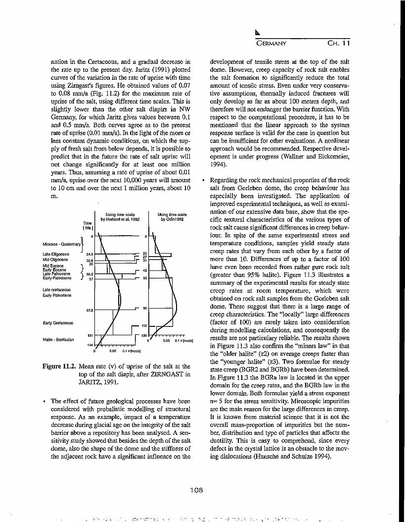
GERMANY CH. 11
nation in the Cretaceous, and a gradual decrease inthe rate up to the present day. Jaritz (1991) plottedcurves of the variation in the rate of uprise with timeusing Zirngast's figures. He obtained values of 0.07to 0.08 mm/a (Fig. 11.2) for the maximum rate ofuprise of the salt, using different time scales. This isslightly lower than the other salt diapirs in NWGermany, for which Jaritz gives values between 0.1and 0.5 mm/a. Both curves agree as to the presentrate of uprise (0.01 mm/a). In the light of the more orless constant dynamic conditions, on which the sup-ply of fresh salt from below depends, it is possible topredict that in the future the rate of salt uprise willnot change significantly for at least one millionyears. Thus, assuming a rate of uprise of about 0.01mm/a, uprise over the next 10,000 years will amountto 10 cm and over the next 1 million years, about 10m.
Using time scalebyOdin1982
Miocane - Quaternary
Late OligoceneMid Oligocene
Mid EoceneEarly EoceneLate PaleoceneEarly Paleocene
Late cretaceousEarly Paleocene
Early Cretaceous
Maim - Berriasian
Using time scalebyHarlandetal. 1982
0.05 0.1 v [mm/a]
0.05 0.1v [mm/a]
Figure 11.2. Mean rate (v) of uprise of the salt at thetop of the salt diapir, after ZIRNGAST inJARITZ, 1991.
• The effect of future geological processes have beenconsidered with probalistic modelling of structuralresponse. As an example, impact of a temperaturedecrease during glacial age on the integrity of the saltbarrier above a repository has been analysed. A sen-sitivity study showed that besides the depth of the saltdome, also the shape of the dome and the stiffness ofthe adjacent rock have a significant influence on the
development of tensile stress at the top of the saltdome. However, creep capacity of rock salt enablesthe salt formation to significantly reduce the totalamount of tensile stress. Even under very conserva-tive assumptions, thermally induced fractures willonly develop as far as about 100 metres depth, andtherefore will not endanger the barrier function. Withrespect to the computational procedure, it has to bementioned that the linear approach to the systemresponse surface is valid for the case in question butcan be insufficient for other evaluations. A nonlinearapproach would be recommended. Respective devel-opment is under progress (Wallner and Eickemeier,1994).
Regarding the rock mechanical properties of the rocksalt from Gorleben dome, the creep behaviour hasespecially been investigated. The application ofimproved experimental techniques, as well as exami-nation of our extensive data base, show that the spe-cific textural characteristics of the various types ofrock salt cause significant differences in creep behav-iour. In spite of the same experimental stress andtemperature conditions, samples yield steady statecreep rates that vary from each other by a factor ofmore than 10. Differences of up to a factor of 100have even been recorded from rather pure rock salt(greater than 95% halite). Figure 11.3 illustrates asummary of the experimental results for steady statecreep rates at room temperature, which wereobtained on rock salt samples from the Gorleben saltdome. These suggest that there is a large range ofcreep characteristics. The "locally" large differences(factor of 100) are rarely taken into considerationduring modelling calculations, and consequently theresults are not particulary reliable. The results shownin Figure 11.3 also confirm the "miners law" in thatthe "older halite" (z2) on average creeps faster thanthe "younger halite" (z3). Two formulae for steadystate creep (BGR2 and BGRb) have been determined.In Figure 11.3 the BGRa law is located in the upperdomain for the creep rates, and the BGRb law in thelower domain. Both formulae yield a stress exponentn= 5 for the stress sensitivity. Miroscopic impuritiesare the main reason for the large differences in creep.It is known from material science that it is not theoverall mass-proportion of impurities but the num-ber, distribution and type of particles that affects theductility. This is easy to comprehend, since everydefect in the crystal lattice is an obstacle to the mov-ing dislocations (Hunsche and Schulze 1994).
108

GERMANY C H . 11
Alle KriochvefsucheGorieben bo-RT
1E-7
0 12 14 16Spannung'(MPa)
z2 Slaflfurt-Slemsalz z3 Uine-Steinsalz
18
Figure 11.3. Stationary creep rates of salt cores fromGorleben.
11.4 KONRAD REPOSITORY PROJECT
11.4.1 Safety assessment and planning
It is intended to emplace into the Konrad repository - anabandoned iron ore mine in the southeast ofNiedersachsen - radioactive wastes which exert a negli-gible thermal influence on the host rock (total activity 5x 10¹⁸ Bq, alpha activity 1.5 x 10¹⁷ Bq). The applicationfor the initiation of a licensing procedure for the Konradrepository project was filed in 1982. A decision on theproject is expected for the near future.
New cavities of about 106 m3 volume will be driven atdepths between 800 and 1300 m for the emplacement ofthe waste. A time of operation of at least about 40 yearsis expected, depending on the amount of waste to be dis-posed of annually.
Because of the licensing authority's opinion on long-term safety, limitations will arise to 7.0 x 10¹¹ Bq for129I and 1.9 x 10¹² Bq for 238U. Due to the long traveltimes from the repository to the biosphere, a potentialradiation exposure of the biosphere will only result inthe case of long-lived radionuclides like 129I and 238Uwith its decay products, and only after hundreds of thou-sands of years and several million years, respectively.These results are taken from model calculations forradionuclide migration in the repository's near and farfield. Since the potential radiation exposure will occur
far beyond a time limit for which it may be assumedwith sufficient reliability that the marginal conditionslike the present geological and hydrogeological situa-tion at the site underlaying the calculations are stillvalid, the results obtained for individual doses only havethe purpose to judge the isolation potential of the site.This opinion of the applicant was discussed controver-sially within the licensing process. More details werepresented by Rothemeyer (1993).
11.4.2 Rock mechanics work
Among others, the following types of measurementshave been carried out:
• measurement of subsidence at ground level using lev-eling;
• measurement of the drop in roof level in the mainlevels;
• measurement of the convergence in the main levelsand exploratory drifts;
• measurement of rock mass deformation above a for-mer working field (flushing field); and
• measurement of rock stresses.
Subsidence was measured using precision levelling on afixed network of 390 points distributed over approxi-mately 40 km2. The results of these measurements maybe summarized as follows:
• The first subsidence occurred approximately oneyear after the start of mining.
• The maximum subsidence of the trough is in the areaabove the flushing field. In May 1985,20 years afterthe start of mining, the subsidence here totaled 264mm. The subsidence trough had a limiting angle ofbetween 35 and 39°.
• During ore extraction the maximum rate of subsi-dence over the southern field was 2.8 mm/month; in1985 this had reduced to only 3 mm/year.
The development over time of the subsidence of level-ling points does not indicate any irregulatrities. Thetrough is subsiding uniformly.
Overall, the subsidence may be considered as small.This is confirmed by the fact that no damage has beenobserved at the surface. The measurement results allowthe assumption to be made that subsidence is close to itsfinal value. A large number of convergence measure-
1 0 9

GERMANY C H . 11
ment stations were set up on the main levels andexploratory drifts. It proved in part possible to carry outinitial measurements very soon after cavity excavation.
The evaluation of the convergence measurements hasprovided the following results:
1. The convergence processes observed in the Konradmine are not based on creep processes, as in rock salt,for example. They are rather related to microfissuringprocesses in the nearby surrounding rock, which leadto deconsolidation of the rock mass.
2. The convergence of the drifts over time may bedescribed using a logarithmic function (Fig. 11.4).
3. The convergence behaviour of the drifts is dependentupon the degree of excavation; the higher the degreeof excavation the higher the convergence.
4. The floors of the drifts frequently show greater con-vergence than the roofs.
5. In drifts which pass through old mine sections theeffects of stress redistribution in the area of the oldworkings are continuing.
Sutaidtnct- 1
TO5 WTO 1J75 TWO 19SS
Figure 11.4. Subsidence and excavation volume versustime, Konrad mine.
In addition, numerical calculations were executed toassess the rock mechanical processes in the overburdenand the stability of the repository. The calculations werecarried out using the Finite Flement Program SystemADINA.
Primary stress measurements were carried out in twoboreholes at borehole depths of approx. 15 m to 25 m.The results are plotted in Figure 11.5. The maximumand minimum stresses are shown as functions of depthof the borehole under study. The measurements allowmaximum values of between approx. -18.0 and -24.5MPa to be read, and minimum values of between
approx. -12.0 and -17.6 MPa. The overall averages are-21.0 MPa (maximum values) and -14.8 MPa (minimumvalues). The maximum stresses are generally subvertical(±20° to +30°) in orientation.
Typical results measured for secondary stresses normalto plane of bedding me given in Figure 11.6 for mea-surement section MQ4 in the pillar between chamber231S and chamber 241S. Here the measured stresschanges were raised by the amount of the theoreticalprimary stress. The measured values show a markeddrop as distance from wall increases. At approx. 10 mdistance stress changes have fallen to minor levels.
As a comparison the results of the numerical model cal-culations are shown. These model calculations arereported in detail in Dickmmn et al. (1991). As Figure11.6 shows, there is good agreement between measuredand theoretical secondary stresses.
Generally, the rock mechanics tests undertaken at theKonrad drift system in field 5/1 have as their mostimportant result that the construction of storage cham-bers in middle Jurassic coal oolite for radioactive wastesgenerating low levels of heat with cross sectional areasof 40 m2 and chamber separations of approx. 35 m canbe safely carried out from a rock mechanical point ofview. The results of the geotechnical measurements per-formed in test field 5/1 do not indicate my risk to stabil-ity of the hard rock and the drifts.
With respect to the test techniques under the difficult in-situ conditions in the underground, the instrumentationproved itself for the most part very well and producedreliable results. The test concept of overlapping andcomplementary test methods has proved itself to be con-structive and expeditious.
11.5 MORSLEBEN REPOSITORY
Short-lived low and intermediate level radioactive wastefrom the operation of nuclear power plants and theapplication of radionuclides in research, medicine andindustry in the former Geman Democratic Republic wasdisposed of in the Endlagerung fur radioaktiver AbfalleMorsleben (ERAM, Morsleben repository for radioac-tive waste) an abandoned salt mine located near the vil-lage of Morsleben (now in the state of Sachsen-Anhalt).
Until 1969, this mine had produced potash and rock salt.The salt was excavated in room and pillar mining downto a depth of about 500 m so that mine openings result-
110

GERMANY C H . 11
£
30
20
10
S
0
K M .
•
aH1K.
0
•
JTKESS
*
aSTXEJS.
THE8KETICSI
•
TMMHETtCKL
•
<Y£HI. Oil
a
(mm. a
"7-
u a swattit J/J«• C 33HEH0U t /»
10 15 20 25
BOREHOLE DEPTH (Hi
30
Figure 11.5. Primary stresses in test field 5/1.
ed with a maximum length of about 150 m and a maxi-mum width and height of about 30 m, respectively. Intotal, a volume of about 7.6 x 10⁶ m3 was excavated andpartly backfilled (2.1 x 10⁶ m3,). Since the first opera-tional license was granted in 1981, the repository hasbeen used for the emplacement of short-lived low andintermediate level waste without the intention ofretrieval. Spent radiation sources were also disposed ofin this facility.
Until 1991, radioactive waste with a total emplacementvolume of approximately 14,500 m3 and about 6,200radiation sources were disposed of. In total, an activityof 1.8 x 10¹⁴ Bq was emplaced. The activity of alphaemitters amount to 1.6 x 10¹¹ Bq, and the activity ofbeta/gamma emitters, to 1.8 x 10¹⁴ Bq. The waste wasmainly delivered by combined rail-and-road transportsusing standardized freight containers. About 2,900 suchcontainers were delivered until 1991.
Since the German Unity in October 1990, the Morslebenfacility has the status of a federal repository. The oper-ating license is limited by law until June 30, 2000.Emplacement of waste has been resumed in January1994. Until the end of the year 1995, 5,691 m3 of wastewith the total activity of 2.6 x 10¹³ Bq [(a: 1.4 x 10¹⁰
Bq] has been disposed of.
11.6 FUTURE RESEARCH WORK
The European Commission has recently performed areview study on the status of understanding of thermal,mechanical, hydrogeological and geochemical proper-ties of host rock formations (Balz, 1995). In general, itwas concluded that the large number of heating experi-ments which have been performed, both in laboratoryand in the field, have provided sufficient knowledge
luzn
(3
5 20
10
KUUKO
CSUUlSTED-r
JKEMETICM.STRESS
1 10 IED01XS FUME
^ e B 10 120I5TRHCE R TO VflU (HI
14 IS
Figure 11.6. Secondary stresses normal to plane ofbedding.
about the nature of the purely thermal aspects and exist-ing models seem to be adequate for predicting theresulting temperature field and its evolution with time.
It becomes more difficult when one has to consider theinfluence of temperature increase on the mechanical,hydrogeological and geochemical properties and in par-ticular to understand and perform predictive modellingof coupled effects.
Therfore, it has also been recognised that the couplings
Table 11.1. Recommendations for research
Priority 1
• Further development of investigation and interpretationmethods for coupled geochemistry/geomechanical/brinemigration models.
• Further studies of geomechanical properties with gas andbrine related parameters as variables.
• Development of consistent thermomechanical models andrelevant codes for backfill material.
• Scientifically based engineering studies to develop perfor-mance criteria for backfilling and sealing techniques.
• In-situ studies of the gas problem.
Priority 2
• Comparison of stress measurements methods and interpre-tation procedures, taking salt creep into account.
• Development of a freshwater/brine groundwater flowmodel, and validation under in-situ conditions.
• Development of models for generation and transport ofgases and brines.
• Optimization of "geoprospective" natural analogue, sce-narios and palaeohydrological methods.
• Testing of backfilling techniques in a URL.
I l l
GERMANY CH. 11
of chemistry with thermo-hydromechanical (THM)processes of the various host rocks is a crucial issuewhich has to be further investigated.
Another subject which has gained attention in recentyears is the issue of gas generation and transport andpossible impact on operational and long term safety. Inany repository for radioactive wastes, gases will beformed due to corrosion of metals, microbial degrada-tion of organic matter and to a lesser extent from radi-olytic decomposition of water and organic compounds.As a consequence, gas pressure will build up in the nearfield until it is released through the system of engineeredbarriers into the geosphere at a rate equivalent to theproduction rate. Research efforts have been undertakento assess the rate of production for various waste forms,disposed of in various host rocks. Moreover, modelshave been developed for describing gas transport and/ortwo phase flow through the geologic formations.However, more research is needed for a better under-standing of basic mechanisms of gas and/or two phaseflow through the host rock or along preferential path-ways, fractures and faults. Site specific data are neces-sary for the assessment of the possible impact of gasgeneration on repository safety. Technical measures areavailable or further being developed to cope with theseissues by appropriate repository design.
Reflecting these results and considering the followingkey questions:
• can a candidate respository site be adequately char-acterised (availability of site characterisation tech-niques and methodology)?
• are thermal, hydrogeological and mechanical proper-ties and processes of salt formations well enoughunderstood (long-term efficiency of the geologicalbarrier)?
• will it be possible to build, operate, backfill and seala repository in salt rock in a safe and economic way(repository design aspects)?
Conclusions for further scientific work have been given(Langer, 1995). Regarding rock salt as host rock the rec-ommendations listed in Table 11.1 can be given. Theaim of this research work is to assure that appropriateuse of safety assessment methods, coupled with suffi-cient information from proposed disposal sites, can pro-vide the technical basis to decide whether specific dis-posal systems would offer to society a satisfactory levelof safety for both current and future generations.
REFERENCES
Langer, M., et al., Empfehlungen des ArbeitskreisesSalzmechanik zur Geotechnik der Untertage-deponierung, Bautechnik 70: 734-744,1993.
Langer, M., Geoscientific evaluation of geological andgeotechnical barriers with respect to waste disposalprojects, Proc. 7th Int. IAEG Congr. 2827-2935,Rotterdam, Balkema, 1994.
Brennecke, P., et al., Final disposal in Germany, Kern-technik 59: 23-27, 1994.
IAEA, Safety Indicators on different time frames for thesafety assessment Tec. Doc. 767, Vienna, 1994.
Rothemeyer, H., ed., Endlagerung radioaktiver Abfalle,VCHVerlagWeinheim, 1991.
Jaritz, W., Die Entwicklungsgeschichte des SalzstocksGorleben, Geol. Jb A132: 3-31,1991.
Wallner, M. and R. Eickemeier, Modelling of conse-quences of future geological processes by means ofprobabilistic methods, NEA-Workshop on SiteEvaluation (SEDE), Paris, 1994.
Hunsche, U. and O. Schulze, Das Kriechverhalten vonSteinsalz, Kali u. Steinsalz 11: 238-255,1994.
Rothemeyer, H., Aspects of a confidence buildingprocess in long term safety evaluation for HWL-repositories, Proc. Int. Conf. Safe Waste, Avignon, p.290,1993.
Diekmann, et al., Geotechnical measurements duringexcavation of parallel drifts, 3rd Int. Symp. FieldMeasurements, Oslo: 561-570,1991.
Balz, W., Research and development on radioactivewaste management, In: IAEA Tec. Doc. 853, 72-87,Vienna, 1995.
Langer, M., Review of R&D requirement on THM prop-erties of salt, In: CEC Proc. Workshop, Testing andModelling of thermal, mechanical and hydrogeologi-cal properties of host rocks, 223-250, Brussels, 1995.
112

CHAPTER 12
HUNGARIAN APPROACH FOR FINAL DISPOSAL O F HIGH LEVEL
RADIOACTIVE WASTE
P. OrmaV, F. Frigyesi1, I. Benkovics2, L. Kovacs2' J. Csicsak2,Gy. Majoros2 G. Erdi-Krausz3 and Gy. Bardosi4
1. Raks, Nuclear Power Plant Ltd., 7030 Paks P.O. Box 71, Hungary2. Mecsek Ore Mining Company, 7633 Pecs P.O. Box 121, Hungary
3. Mecsekuran Ltd., 7614 Kovagoszolos, P.O. Box 65, Hungary4. Corresponding Member, Hungarian Academy of Sciences, 1055 Kossuth sq 18, Budapest, Hungary
12.1 INTRODUCTION
LI Hungary, nuclear power provides a substantial por-tion of the total electricity produced in the country. ThePaks Nuclear Power Plant (NPP) contains four VVER-440 nuclear reactors, each capable of producing 460MW of electricity. This plant regularly produces morethan 40% of the electricity consumed in Hungary. Thereis currently no plan to increase the electrical generatingcapacity of Hungary, but if future additions to nuclear-based electrical generation were to be made, they wouldsignificantly increase nuclear power's share of electrici-ty consumed.
Fuel for the Hungarian NPP, as is the case for all otherEast European VVERs, has been supplied hi the past bythe ex-Soviet Union. As part of the fuel agreement, theSoviet Union was obliged to take back and dispose of allspent fuel (using another supplier would leave Hungarywith the problem of high level waste disposal). In thepast, Hungary was glad to have the problem of disposaldealt with in this way. Now, although contracts for fuelsupply and return are still in force, Hungary is less cer-tain how long this "comfortable arrangement" will last.
The shipment of spent fuel for 1992 was ready for dis-patch but has been delayed due to problems with trans-port through the Ukraine. It is understood that Russia,while they may still be prepared to take and processspent fuel, will now send the high level waste back toHungary for disposal. The cost of such disposal will becharged to the Paks NPP operation and, therefore, futurecosts are likely to increase.
This likely interruption of the current spent fuel dispos-
al route may lead to a fairly immediate problem inHungary. The spent fuel ponds will be totally full by theend of refueling in 1995. It is therefore necessary for anew program for removal of fuel from the ponds to beimplemented before the 1996 refueling to avoid thenecessity to shutdown the reactors.
The current intention is to build an interim storage facil-ity to hold spent fuel after it has completed five years ofcooling in the ponds. In 1993, a decision was made toconstruct a Modular Vault Dry Store at Paks based onthe GEC Alsthom design, which was first used at FortSt. Vrain (USA). At some point in the future, the fuelwould either be packaged for direct disposal, orreprocessed outside the country and the high level vitri-fied waste returned to Hungary for disposal.
As insurance against the waste remaining in Hungary orbeing returned after reprocessing, it is highly desirableto proceed by planning for possible disposal of spentfuel some 50 years or more in the future.
Normally, the siting of any HLW repository should bestarted by screening the entire country for suitable loca-tions. However, as a result of preliminary investigations,Hungary has a geological formation that is considered atleast as a national "treasure." This is a siltstone, anUpper Permian red-colored formation, covering some150 sq. km. Its thickness from borehole drilling is about800-900 m.
Based on preliminary assessments and technical consid-erations, the use of the Permian Boda claystone forma-tion in the Mecsek Mountain area is being consideredfor HLW disposal. To evaluate the suitability of this for-
113

HUNGARY CH. 12
mation as a location for a waste repository, investiga-tions have started with the technical assistance of theAtomic Energy of Canada, Ltd.
12.2 SPENT FUEL CHARACTERISTICS
The radioactivity and heat output of a spent Paks NPPfuel assembly is similar to spent fuel assemblies fromother pressurized water reactors for the same burnup.However, the geometry and components of these fuelassemblies are different from those of fuel assembliesfrom other pressurized water reactors. Two types of fuelassemblies are used in the Paks NPP, the operationalassembly and the follower part of the absorbers. Bothtypes have a hexagonal cross section with a key dimen-sion across the flat side of the hexagon of 144.2 mm.
Each assembly contains 126 fuel rods in a hexagonalarray and surrounded by a hexagonally shaped tube.This tube is fabricated from an alloy containing 97.5%zirconium and 2.5% niobium. The fuel rods consist ofUO2 pellets contained in a tube made from a 99% zirco-nium and 1% niobium alloy. The inside and outsidediameters of the cladding tube are 7.72 mm and 9.15mm, respectively.- The assembly top head, nozzle unitsand spacers (10 per assembly) are made from stainlesssteel. The overall length of the operational fuel assem-bly is 3,217 mm and the active length is 2,470 mm. Thetotal weight of the operational assembly is 215 kg,which includes 120.2 kg of fissile material. The differ-ences between the Paks NPP fuel assembly and a typi-cal pressurized water reactor fuel assembly would notpreclude direct disposal of the spent Paks assemblies ina repository.
Assuming a 30-year operational life for each reactorunit and no change in the fuel cycle, 15,316 spent fuelassemblies will be discharged from the Paks NPP.
12.3 OPTIONS FOR SPENT FUEL MANAGEMENT
Paks NPP Ltd. had two contracts with the Soviet Union(now Russia): one, on the governmental level, address-ing the fresh fuel supply; and the other, a private, low-level contract covering the shipment of spent fuel backto Russia. Furthermore, in April 1994, a new protocolwas signed between the governments of Russia andHungary complementing the earlier governmental con-tract. The protocol confirmed that the fresh fuel forPaks NPP will be supplied by Russia, and Russia isready to receive Hungarian spent reactor fuel. In spiteof the new protocol, the Hungarian government was not
able to ship spent fuel to Russia in 1994. Because ofcurrent difficulties and the fact that the protocol does notcontain a guarantee that Hungarian spent fuel will bereturned to Russia, there is a very low probability thatlong-term shipment of Paks NPP spent fuel to Russiawill be realized. Therefore, it is assumed that in the longterm, the return of spent fuel to Russia will not be pos-sible.
The Hungarian government and Paks NPP Ltd. had toconsider developing a program to manage the spent fuelassemblies from the existing Paks NPP and from anyfuture nuclear power placed in operation in Hungary.This program would be similar to spent fuel strategies ofother small W E R operators, such as the Czech andSlovak Republics and Finland. It is also consistent withthe current international tendency of each country oper-ating nuclear reactors to develop an independent high-level waste management strategy for storage and dis-posal.
The options available to Hungary for the management ofspent fuel include: reprocessing, direct disposal or adeferred (wait and see) decision between these twooptions. In the latter case, the spent fuel would be storedin Intermediate Spent Fuel Store (ISFS) for approxi-mately 50 years. Each of these options, for the backendof the fuel cycle, requires a geological repository fordisposal of HLW. For the reprocessing option, the wasteforms would be vitrified fission products, plutoniumwaste (if mixed oxide fuel is not acceptable) and even-tually fuel assemblies (when the fissile material can nolonger be recycled). For the direct disposal option, thewaste form would be one or more types of spent fuelassemblies in containers. For the wait and see option,the waste form will depend on whether reprocessing ordirect disposal is selected as the management strategy atthe end of the storage period.
12.4 GEOLOGICAL FORMATIONS TO BE EVALUATED
The long-term management of high-level radioactivewaste has only recently become an issue in Hungary.Concurrent with the attempts to return spent fuel toRussia, a decision was made to erect an ISFS at PaksNPP, and this facility is now being constructed. Thedecision concerning the spent fuel management optionat the end of the interim storage period has not beenmade.
Because of the geology of Hungary, only a limited num-ber of potentially suitable disposal sites for high level
114
HUNGARY C H . 12
waste are available within the country. One of these is aPermian claystone deposit called the Boda ClaystoneFormation near the city of Pecs in SouthwesternHungary. The uranium mine is located in a Permiansandstone formation close to part of this claystone for-mation. The formation has also been investigated as apotential host for low-level waste disposal. When high-level disposal became a concern for Hungary, theMecsek Ore Mining Company proposed that the BodaClaystone Formation, of Permian age, be investigatedfor its suitability as host rock for a Hungarian nuclearwaste repository. Information about the lithology andstructure of the overlying sandstone has been collectedduring uranitun mining over the past 40 years.
Useful information about, the groundwater flow condi-tions of the sandstone has also been collected from themining operations. About 50 boreholes were drilledfrom surface to investigate the uranium deposits in thesandstone. Four boreholes have penetrated the underly-ing Boda Claystone Formation to considerable depths (afew hundred meters). Two of these boreholes weredrilled in 1991 to 1200 m depth to obtain informationabout the vertical characteristics of the claystone overmost of its thickness. In 1993, a specific study programwas started within the framework of the National WasteDisposal Program to further examine the BodaClaystone Formation. The following activities havebeen carried out under this program:
• several underground core drilled boreholes;• an access tunnel (280 m length), about 80 m into the
Boda Claystone);• systematic sampling in the tunnel;• geological mapping (and documentation) of the tun-
nel walls including the subsequent tunnel faces;• hydrogeological boreholes, corresponding measure-
ments, and collection of water samples;• rock mechanics measurements during the excavation
of the tunnel, and after completion;• geophysical measurements;• geochemical, mineralogical and geomechanical labo-
ratory investigations in affiliated institutions; and• laboratory testing of water samples.
So far, the investigations from this exploratory tunneland two previous deep surface boreholes, BAT-4 andBAT-5, indicate that the Boda Claystone Formation is ahighly compact rock unit of very low overall permeabil-ity (<10"10 m/sec). Based on an understanding of thefaults, fractures and their relative movements from stud-ies of the overlying uranitun bearing sandstone, it is
believed that most of the faults in the claystone aresealed and filled with calcite, barite, gypsum and clayminerals. The accumulated data suggests there are onlya few widely spaced fault zones in the Boda ClaystoneFormation. Methods to determine the location, orienta-tion, extent and hydrogeologic characteristics of thesefaults are currently being assessed.
The objective of all the above studies was a preliminarycharacterization of the Boda Claystone Formation as apotential host rock for a high-level radioactive wasterepository. The results obtained so far confirm the geo-chemical and hydrogeologic suitability of the claystonefor HLW disposal and favor further investigation of thisclaystone formation. This is particularly the case in viewof the fact that there is not a wide choice in Hungary ofsuitable geological formations (size and quality) for aHLW repository.
12.5 GEOLOGICAL STRUCTURE OF THE AREA
The Western Mecsek Mountain Permo-Triassic inlier isbounded to the north, south and east by three left-later-al, strike-slip faults. These enclose gently eastward-plunging (~10°) folds. A broad anticline, flanked bysmaller synclines, contains the detailed area of interest,and is bounded to the north by a 30° south-dippingreverse fault, and to the south by a 50° north-dippingreverse fault. Both of these faults strike east-northeastand are paralleled by lesser reverse, normal and oblique-slip faults with high intermediate to subvertical dips thatare connected by splays in some cases. A further set ofeast-dipping normal faults strike north-northwest, per-pendicular to the anticlinal axis.
The stratum of interest, the Boda Claystone Formation,is a silty claystone at least 800 m thick. This is a lacus-trine deposit set within a sequence of fluvial sandstonesall of which were deposited in a semi-arid climatic envi-ronment. The claystone is bounded beneath by a con-glomeratic sandstone (Cserdi Formation) concordantlygradational over 100 m. It is bounded above by anotherconglomeratic sandstone (Kovagoszolosi Formation),which contains the uranium deposits mined byMecsekuran Ltd. This upper contact is gradational over40 m but is discordant in places.
The Boda Claystone Formation is exposed at the surfaceover an area of about 20 km2 near the village of Boda.In order to evaluate this formation, it will be necessaryto study the entire unit, down dip from the surface out-crop towards Shaft IV (transportation and ventilation)
115

HUNGARY CH. 12
Area for initialcompilation of pastdata and in which toconcentrate field worl
Area in which tochoose fault-boundedblock for drilling 3boreholes
Area in which to drill1 hole for lowerstratigraphy
Proposed areB forEM survey
Figure 12.1. Proposed surface geological and geophysical investigations.
and Shaft V (transportation). This will define a candi-date area of approximately 40 to 50 square kilometers,as shown in Figure 12.1. The tentative regional studyarea is marked on Figure 12.2 by boundary IJKL. It isestimated to contain about 40 cubic kilometers of BodaClaystone Formation with an average thickness of 800m, in which exploration can be carried out for the selec-
tion of possible disposal sites. The northern boundarycould be extended further to I T , if necessary.
Being a lacustrine deposit, the Boda ClaystoneFormation, probably varies lithologically over muchlarger distances laterally than vertically. It contains sev-eral stratigraphic members in the vertical, stratigraphic
116

czo>
n
Figure 12.2. Geological map showing proposed study area. K)

HUNGARY C H . 12
section, without obvious boundaries but with slightlydifferent properties. In general, the chemical composi-tion is quite uniform throughout stratigraphically; it iscomposed of quartz and feldspar with a high clay con-tent and a significant amount of fine grained hematite.The claystone has a higher quartz content in the upperpart of the formation, and the matrix contains up to 10%primary dolomite in layers 1-10 cm thick. The clay-stone is generally oxidized but a few unoxidized layersare evident in the geologic logs of some boreholesdrilled from the surface. These layers can be at least upto 20 m thick.
Knowledge of the location, extent and hydrogeologicproperties of fault zones and fractures within the BodaClaystone Formation is of critical importance in select-ing a suitable location for a high-level waste repository.Based on geologic mapping of the overlying sandstonein the uranium mine, it is clear from a WSW-ENE cross-section that the 700 to 900 m thick claystone stratummay be offset by a number of WSW-ENE trending frac-ture zones. This claystone may also be affected bynorth-south trending subvertical faults. From recentmapping in the "Alpha" exploratory tunnel at the 1100m depth in the mine, two dominant sets of mesoscopicfractures have been observed in the Boda ClaystoneFormation. These fractures are filled with calcite andclay minerals, and are apparently sealed to groundwaterflow. It will be essential to develop a much moredetailed understanding of the lithological, hydrogeolog-ical, geophysical, geochemical and geomechanical con-ditions of this claystone and adjacent formations andcrosscutting faults to develop performance assessmentmodels in order to evaluate different areas of the BodaClaystone Formation for a high-level waste repository.
12.6 CHARACTERIZATION PROGRAM OUTLINE
The region of the Boda Claystone Formation that hasbeen identified as a potential siting area will require acomprehensive characterization program to select thepreferred disposal site. The existence of an access tun-nel from the uranimn mine into the claystone at 1100 m,provides an opportunity to characterize some potential-ly important vertical structures that could act as ground-water pathways through the claystone. Thus, the char-acterization program for this particular area in the BodaClaystone differs from the program that would be devel-oped for a site or formation where there is no existingunderground access.
The characterization activities are part of a long-term
program that could take 7 to 15 years to complete beforea final disposal site in the Boda Claystone is approved.However, there is a need to determine whether or not along-term program should be initiated in the BodaClaystone. The objective of this short-term program isto consolidate the information that has been gatheredduring 40 years of mining related activities in thisregion, collect new information from selected targetareas and develop a comprehensive geotechnical modelfor the region.
Very slow groundwater movement or diffusion withinpores and fractures in the Boda Claystone Formation,surrounding the site eventually chosen for the reposito-ry, is expected to provide an effective barrier to therelease and migration of repository contaminants.Adsorption on the clays in the rock matrix and fracturefillings is also expected to be a major factor in retardingthe contaminants. Thus, a thorough knowledge of thegroundwater flow and diffusion paths through the clay-stone and adjacent rock formations is required to deter-mine the likely pathways for radionuclide migrationfrom potentially suitable repository locations to thehuman environment.
The main problem in characterizing the candidate areais to choose a location for the repository such that thehydrogeologic and geochemical conditions will delayand impede the release and migration of repository con-taminants to the accessible human environment. Thiswill involve both surface and underground evaluationsof the Boda Claystone Formation and the overlying andunderlying sandstone formations in the candidate area.
A major emphasis in the site characterization programwould be on developing an understanding of the physi-cal and chemical conditions of the groundwater path-ways in the claystone and determining how these condi-tions interact with the fluid flow conditions in the over-lying and underlying rock formations. Another empha-sis would be on determining any future change or dis-ruptions that could affect these flow conditions. Stillanother emphasis would be on determining how anyfuture changes or disruptions, during the construction oroperational stages of the repository or during the timeframe of concern for long term assessments of perfor-mance, could affect groundwater movement in the BodaClaystone Formation.
Because this claystone has a very low primary perme-ability, yet is situated in a geologic setting that has beenfaulted and fractured, it will be necessary to determine
118

HUNGARY C H . 12
the geometry and hydraulic properties of the fracturingat different scales within the formation to develop anunderstanding of the groundwater flow conditions. Thegroundwater regime in the overlying Permian sandstonehas been dramatically affected by the uranium miningactivity, and therefore, it will differ from original condi-tions. The disturbed hydrogeological regime in the over-lying Permian sandstone may have altered the ground-water conditions in the Boda Claystone, and theseeffects will also need to be evaluated.
The data gathered from these activities and data alreadycollected by Mecsek Ore Mining Company, and otherHungarian institutions can be used to select a preferredsite for a HLW repository within the potential sitingarea. There are two possible alternatives that wouldaffect the characterization program. They are:
• the preferred repository site is close enough to theuranium mine so that the site can be accessed fromthe mine; or
• the preferred site is located such that a new accessfrom the surface would be necessary or preferred.
If the preferred repository site is chosen near the loca-tion of the uranium mine in the overlying sandstone soas to be accessible from the mine, the local characteri-zation program would include some surface boreholesto provide information immediately around the reposi-tory. However, the majority of the characterization pro-gram would probably be conducted underground fromcurrently existing and new access tunnels.
If the preferred repository site is located away from theuranium mine where new access from the surface isrequired or preferred, the initial characterization will bemainly from the surface into the undisturbed portion ofthe Boda Claystone Formation and will progress logi-cally to underground characterization activities as newaccess to the underground is constructed.
Under normal circumstances, a characterization pro-gram to select a preferred site for a HLW repositorywould initially be surface based, followed by an under-ground evaluation program at the preferred site usingexploratory shafts and tunnels. This is the approach rec-ommended by Davison et al., for the Canadian nuclearfuel waste disposal concept. In the case of the BodaClaystone Formation, the underground environment hasalready been accessed by an underground tunnel at 1100m depth from the adjacent uranium mine, thus providingthe opportunity to conduct further underground charac-
terization activities, if there are both cost and technicaladvantages to doing so.
Because the area presently under consideration as anuclear fuel waste disposal site is relatively large (40km2), both surface-based and underground characteriza-tion programs are recommended. One of the normaladvantages of a surface-based characterization programis that the underground environment is relatively undis-turbed prior to excavation. This allows backgroundmeasurements of the undisturbed conditions at the siteto be obtained from a network of surface-based charac-terization boreholes, and allows the construction of adetailed model of the groundwater regime at the site.Predictions of drawdown resulting from shaft sinkingand the excavation of exploratory tunnels can be madeand compared to actual measurements to assess theaccuracy of the hydrogeological model.
For the characterization of the Boda ClaystoneFormation, the fact that many of the potential faultsextending down from the overlying sandstone formationare sub-vertical means that they are better accessed andinstrumented using sub-horizontal boreholes that areeasily drilled from the underground. However, there aresignificant operational problems associated with con-ducting characterization activities from the under-ground. Firstly, there may be limitations on the drillingof long exploratory boreholes underground due to tech-nical factors. The drills presently used underground atthe uranium mine are apparently limited to drilling bore-holes to a maximum length of 300 m. Suitable equip-ment to drill longer, and perhaps larger diameter bore-holes would need to be acquired. In addition, the ambi-ent rock temperature at the depth of the present accesstunnel into the Boda Claystone Formation is about 45°C. If this exploratory tunnel is advanced further into theclaystone, the distance to the closest shaft will increase,and with it the problem of cooling and ventilating theworking areas.
The present laboratory tests and measurements from theexploratory access tunnel were finished by the end of1994. Based on the encouraging results of these char-acterization activities, further investigation of the BodaClaystone Formation as a host formation for HLWdisposal was recommended; there is not an abundantchoice of suitable geological formations (size and qual-ity) in Hungary for siting and for economic reasons.
The activities recommended for characterizing the BodaClaystone Formation, both surface-based and under-
119
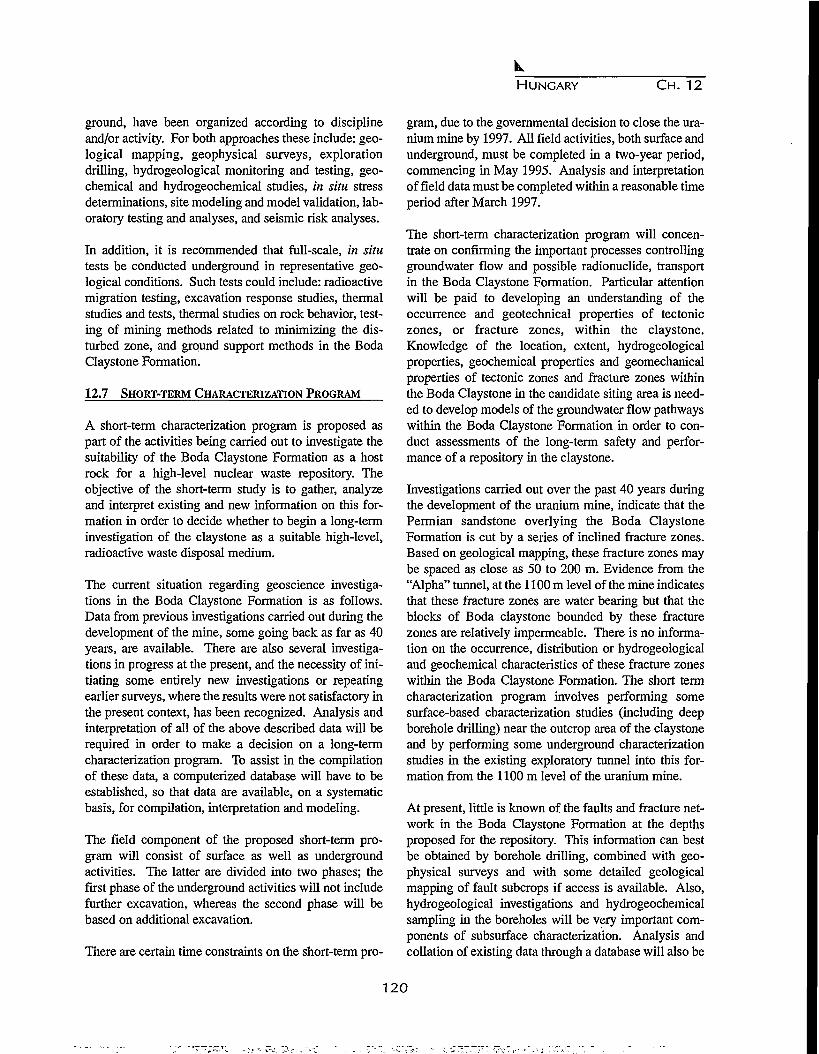
HUNGARY CH. 12
ground, have been organized according to disciplineand/or activity. For both approaches these include: geo-logical mapping, geophysical surveys, explorationdrilling, hydrogeological monitoring and testing, geo-chemical and hydrogeochemical studies, in situ stressdeterminations, site modeling and model validation, lab-oratory testing and analyses, and seismic risk analyses.
In addition, it is recommended that full-scale, in situtests be conducted underground in representative geo-logical conditions. Such tests could include: radioactivemigration testing, excavation response studies, thermalstudies and tests, thermal studies on rock behavior, test-ing of mining methods related to minimizing the dis-turbed zone, and ground support methods in the BodaClaystone Formation.
12.7 SHORT-TERM CHARACTERIZATION PROGRAM
A short-term characterization program is proposed aspart of the activities being carried out to investigate thesuitability of the Boda Claystone Formation as a hostrock for a high-level nuclear waste repository. Theobjective of the short-term study is to gather, analyzeand interpret existing and new information on this for-mation in order to decide whether to begin a long-terminvestigation of the claystone as a suitable high-level,radioactive waste disposal medium.
The current situation regarding geoscience investiga-tions in the Boda Claystone Formation is as follows.Data from previous investigations carried out during thedevelopment of the mine, some going back as far as 40years, are available. There are also several investiga-tions in progress at the present, and the necessity of ini-tiating some entirely new investigations or repeatingearlier surveys, where the results were not satisfactory inthe present context, has been recognized. Analysis andinterpretation of all of the above described data will berequired in order to make a decision on a long-termcharacterization program. To assist in the compilationof these data, a computerized database will have to beestablished, so that data are available, on a systematicbasis, for compilation, interpretation and modeling.
The field component of the proposed short-term pro-gram will consist of surface as well as undergroundactivities. The latter are divided into two phases; thefirst phase of the underground activities will not includefurther excavation, whereas the second phase will bebased on additional excavation.
There are certain time constraints on the short-term pro-
gram, due to the governmental decision to close the ura-nium mine by 1997. All field activities, both surface andunderground, must be completed in a two-year period,commencing in May 1995. Analysis and interpretationof field data must be completed within a reasonable timeperiod after March 1997.
The short-term characterization program will concen-trate on confirming the important processes controllinggroundwater flow and possible radionuclide, transportin the Boda Claystone Formation. Particular attentionwill be paid to developing an understanding of theoccurrence and geotechnical properties of tectoniczones, or fracture zones, within the claystone.Knowledge of the location, extent, hydrogeologicalproperties, geochemical properties and geomechanicalproperties of tectonic zones and fracture zones withinthe Boda Claystone in the candidate siting area is need-ed to develop models of the groundwater flow pathwayswithin the Boda Claystone Formation in order to con-duct assessments of the long-term safety and perfor-mance of a repository in the claystone.
Investigations carried out over the past 40 years duringthe development of the uranium mine, indicate that thePermian sandstone overlying the Boda ClaystoneFormation is cut by a series of inclined fracture zones.Based on geological mapping, these fracture zones maybe spaced as close as 50 to 200 m. Evidence from the"Alpha" tunnel, at the 1100 m level of the mine indicatesthat these fracture zones are water bearing but that theblocks of Boda claystone bounded by these fracturezones are relatively impermeable. There is no informa-tion on the occurrence, distribution or hydrogeologicaland geochemical characteristics of these fracture zoneswithin the Boda Claystone Formation. The short termcharacterization program involves performing somesurface-based characterization studies (including deepborehole drilling) near the outcrop area of the claystoneand by performing some underground characterizationstudies in the existing exploratory tunnel into this for-mation from the 1100 m level of the uranium mine.
At present, little is known of the faults and fracture net-work in the Boda Claystone Formation at the depthsproposed for the repository. This information can bestbe obtained by borehole drilling, combined with geo-physical surveys and with some detailed geologicalmapping of fault subcrops if access is available. Also,hydrogeological investigations and hydrogeochemicalsampling in the boreholes will be very important com-ponents of subsurface characterization. Analysis andcollation of existing data through a database will also be
120

HUNGARY C H . 12
very useful.
Because of the time constraint, only a largely conceptu-al model of the controls on groundwater flow throughthe Boda Claystone, as opposed to a partly idealizeddeterministic model, can be developed. Therefore, thesurface investigations are to be concentrated in a fewareas (at least two) from which a good understanding ofthe principal factors controlling the flow of groundwatercan be obtained.
It is suggested that the surface geological investigations(surface mapping) be confined to the same area as theproposed geophysical surveys. The two principal objec-tives of surface mapping are to:
1. determine the location and conduct fault-rock char-acterization for the subsurface projection of faults inthe Boda Claystone, especially those that are poten-tial drilling targets. This can be achieved by detailedmapping, from outcrops or trenches, of topography,mesoscopic fractures, rock alterations and fracturefillings. This work will be concentrated in the area inwhich a fault-bounded block is likely to be chosen asa drilling target.
2. determine the general character and history of duc-tile, brittle deformation of the Boda Claystone, anddecide whether lithologic variation is likely to beimportant. For example, the bedding attitude data inthe underground tunnel into the Boda Claystone fromthe 1100 m level of the mine suggest crossfolding inthe claystone with a NW to NNW plunge. Suchzones of folding may be centers for more concentrat-ed mesoscopic fracturing.
Drilling and geoscientific and geotechnical characteri-zation of four deep boreholes from the surface is pro-posed. Three boreholes are to be drilled to investigateconditions and to characterize the bounding faults with-in two adjacent fault-bounded blocks within a 3-4 kmradius to the northeast of the village of Boda. Boreholedepths would depend on the actual location chosen, buttwo of them should be 500-700 m deep. The third shouldbe at least 1300 m deep and penetrate the sandstonefootwall. The fourth borehole is to be drilled approxi-mately two km northwest of Boda within the outcrop ofthe Boda Claystone Formation. This hole is also expect-ed to be about 1300 m in depth to obtain hydrogeologicinformation in an area expected to have sparse faulting.This borehole should penetrate well into the footwalland be used to characterize the lower members of theBoda Claystone Formation, geoscientifically and geo-
technically.
12.8 CONCLUSIONS AND PROSPECTS
In 1993, the decision was taken to develop a relativelyinexpensive access from the existing mine to study theadjacent formations. This involved developing and ser-vicing an exploratory access tunnel from the uraniummine into the Boda Claystone Formation. This explora-tory access was completed in 1994. The tunnel has beenused to conduct a preliminary research program to studythe in situ characteristics and properties of the claystone.These data have contributed to assessing the potentialsuitability of the Boda Claystone for high-level wastedisposal in terms of safety assessment and repositorydesign. The results from these preliminary studies havecontinued to confirm the geochemical, geomechanicaland hydrogeologic suitability of the Boda Claystone asa host media for high-level waste disposal in Hungary.
As the Boda Claystone Formation has been identified asa potential high-level waste disposal site, experts arenow developing a thorough program to assess its suit-ability. This will require that sufficient data be gatheredon the characteristics of the claystone to select appro-priate location(s) for a repository and to complete asafety assessment for a repository at each location. Anextensive database of geologic formations exists for thearea of the uranium mine, both from the previous sur-face-based exploration programs as well as from theunderground characterization program. Much of infor-mation is relevant to understanding conditions in theBoda Claystone beneath the uranium bearing Permiansandstone. The structural information on jointing andfracturing is particularly relevant to the identification ofsuitable locations for a high level waste disposal reposi-tory.
The most probable way for radionuclides, that are sealedin a deep geological repository to reach humans and theenvironment is by transport in groundwaters through thepores and cracks in the rock surrounding the repository.Therefore, one major requirement in characterizing pos-sible repository sites in the Boda Claystone Formation isto quantify the important processes governing the trans-port and absorption of radionuclides within the ground-water systems in the rock mass as well as the engineeredbarriers used in the repository. Groundwater movementin rocks such as the Boda Claystone is mainly controlledby the presence or absence of fractures, the permeabili-ty and interconnectivity of these fractures, the perme-ability and porosity of the unfractured rock, and ground-
121

HUNGARY CH. 12
water pressure gradients. The chemistry of the ground-water, the rock matrix, and minerals within the fracturesalso govern the potential transport of radionuclideswithin groundwater. Therefore, the presence of openfractures (joints and bedding planes), fracture zones andprocesses that can change their hydraulic or chemicalproperties, must be understood for repository siting anddesign.
Two underground facilities are likely to be necessary forthe characterization of a site and the design of a reposi-tory in the Boda Claystone Formation. The first facilityis the Underground Characterization and Test Facility(UCTF) that is being started with the construction of theAccess Tunnel from the Mecsekuran uranium mine intothe claystone. It will be used to provide information onthe suitability of the claystone as a repository mediumas well as preliminary repository design information,and to train staff, develop methods and study design andsafety issues. Because it is located near the uraniummine and the contact between the sandstone and theclaystone, it is likely to be in a disturbed environment.
The second facility is a repository characterization facil-ity (RCF), to be located at the preferred repository site,which would be constructed late in the site characteriza-tion stage. It would provide access to the repositoryrock volume for final assessment of the site suitability,and for commissioning and longer-term coupled interac-tion tests on repository systems and components. Itwould be incorporated into the repository design so thatits excavations would become part of the repository andwould not interfere with the repository operation.
The UCTF will be located in a section of claystone thatlikely has been influenced by the mine construction andoperation. In particular, the groundwater pressures,flows and chemistry in the sandstone, and perhaps theclaystone, are likely to be affected by the presence of themine. As there has not been a long-term hydrogeologi-cal monitoring program in the sandstone and claystonenear the mine, the original groundwater conditions andthe magnitude and areal extent of the disturbance causedby mining activities over time are not known.
Without this information, studies and demonstrationsthat require regional groundwater conditions as a step inplanning or in performance and safety related analysesmay not be possible with the limited data gathered fromthe UCTF. These studies will have to planned as part ofRCF activities at a preferred repository site where thesedata can be collected. However, significant groundwa-
ter studies can still be done in the UCTF to:
• develop and demonstrate the equipment, instrumen-tation and procedures for drilling and monitoringgroundwater conditions in boreholes;
• install monitoring systems in new and existing bore-holes to study the hydraulic connections in fracturedrock; and
• observe the pressure and chemistry changes thatoccur when new boreholes and excavations are done.
These are valuable and necessary studies in preparingfor the characterization of a potential repository site, andfor the environmental and safety assessments. Thesestudies will also be used to select the methodologies thatshould be applied in the characterization and assessmentstudies that will be conducted at the preferred reposito-ry site.
Also, it is our understanding that the mine operationshave been confined to the sandstone formation. Thismay make it possible to assess the impact of a large"drain" (i.e.,. the mine in the sandstone and the UCTF inthe claystone) on the pore water pressures within theBoda Claystone Formation. If it can be demonstratedthat the pore pressures in this claystone have been onlyslightly affected by the presence of the mine and thedevelopment of the UCTF, this information can be usedto demonstrate the large-scale low permeability of theclaystone, an attractive characteristic for waste disposal.This type of in situ information can only be obtained bymonitoring the response of the groundwater system toconstruction of underground excavations such as theaccess tunnel and the UCTF.
The effects of the mine excavations on the mechanicalconditions in the claystone around the UCTF will prob-ably not significantly influence the studies and demon-strations that may be planned for the facility. However,the proximity of the UCTF to the contact between thesandstone and the claystone may have to be consideredin analyzing the data from UCTF studies and in extend-ing the results to a potential repository site elsewhere inthe claystone.
The second underground facility, the repository charac-terization facility (RCF), would be constructed at thepreferred repository site during the later stages of repos-itory site characterization to conduct tests: (a) to confirmthe suitability of the site for disposal; (b) complete therepository design; and (c) refine and test repository sys-tems and components. The RCF design would be inte-
122

HUNGARY C H . 12
grated into the repository. As the repository site willlikely be several kilometers away from the uraniummine and away from any other underground excava-tions, it should have a relatively undisturbed groundwa-ter environment. In the site characterization program atthe potential repository site, the regional characteriza-tion and the long-term hydrogeological monitoringwould be done prior to any underground excavation sothe baseline hydrogeological and chemical conditionswould be known. The changes in these conditionscaused by additional borehole drilling, and by the exca-vation and testing in the RCF would be known. Thechanges in these conditions caused by additional bore-hole drilling, and by the excavation and testing in theRCF would be measured and could be used to developand test computer models that will be used to predict theperformance of the groundwater system.
REFERENCES
Buday, G., Recent status of spent fuel storage inHungary and outlook to the future, IAEA AGM,Vienna, April 15-18, 1992.
Buday, G., and G. Ferenczi, Status of the nuclear fuelcycle back-end strategies, IAEA TGM, Vienna, June1-4,1993.
Ormai, P., L. Marothy, and K. Berci, Hungarian policy,on the back-end of the fuel cycle, VVER NuclearWaste Management Workshop 92, Toronto,Canada,1992.
Vigassy, J., I. Czoch, and P. Ormai, Hungarian experi-ence with the National Project for RadwasteManagement, Symposium on Waste Management,Tucson, USA, 1994.
A recommended program for the characterization of theBoda Claystone Formation as a potential site for thesafe disposal of high-level radioactive wastes, Reportby AECL Research, 1995.
Design requirements for the construction and operationof an underground characterization and test facility inthe Boda Claystone Formation, Report by AECLResearch, 1993.
123
124
CHAPTER 13
STATUS OF SITING AND HOST ROCK CHARACTERIZATION PROGRAMME
FOR A GEOLOGICAL REPOSITORY IN INDIA
R.K.Mathur, P.K.Narayan and A.N. Prasad
Bhabha Atomic Research Centre, Bombay-400085, India
13.1 INTRODUCTION
The Indian programme in search of suitable sites forlocation of a deep geological repository for disposal ofhigh level vitrified waste has been in progress for thelast few years. The whole country has been screened,based on well identified criteria, for suitable host rockformations in tectonically stable areas. The programmeis being pursued in a phased manner in stages, to narrowdown the choice from larger areas to a few candidatesites of specific size. In parallel, a study is underway todirectly evaluate and characterize the host rock lyingwithin the exclusion zone of a nuclear power plant forlocating a possible waste repository.
The main host rock under consideration is a plutonicgranitic formation available in tectonically stable areasand having homogeneous and uniform geological, struc-tural, physico-chemical and hydrogeological character-istics with a favorable socioeconomic environment.
Out of thousands of square kilometers of granitic areasscreened, the choice has been narrowed down to a fewgranitic zones of 100 -150 sq. km. Two such zones havebeen investigated in detail to further demarcate the mostsuitable sub-zones. Micro level investigations are to betaken up in the sub-zones to assess the possibility offinding the repository candidate sites.
In one of the sites, geological, hydrogeological, geo-physical (preliminary), environmental and socioeco-nomic surveys have been completed, whereas in theother, deep drilling down to a depth of 620 metres is inprogress. Simultaneously, laboratory investigations toevaluate mineralogical, petrographical, micro-structural,thermal, mechanical, physical and chemical propertiesof the rockmass are also in progress. Modeling studiesfor joint fracture characterizations, ground water flowand radionuclide migration, and stress behavior in a
conceptual repository have been taken up. Geophysicalsurveys, bore hole logging and in-situ stress measure-ment are underway.
13.2 REPOSITORY SITE SELECTION PROGRAMME
The programme is aimed at selecting one or more geo-logical repository sites and characterizing them for finaldisposal of immobilized high level radioactive waste,through various stages of investigations comprising fieldand laboratory studies. To carry out the multi-discipli-nary investigations, a number of national expert organi-zations/agencies have been involved to address specificissues.
13.2.1 Major Site Selection Criteria
The major criteria on which the selection of a candidaterepository site depends are:
• Tectonic stability of the area;• Three dimensional homogeneity, large extent and
massiveness of the host rock mass;• Suitable hydrological and hydrogeological environ-
ment;• Favorable thermal, thermomechanical and geochem-
ical properties of host rock; and• Favorable socioeconomic factors.
13.2.2 Stages of Site Selection
The approach followed for site selection is to narrowdown the choice of the area with an increasing level ofconfidence. This is planned to be achieved in differentstages, reducing the size of the area to smaller entities atevery stage. The following main stages are considered:
Stage I. Collection of all available data from varioussources and their interpolation to evaluate specific
125

INDIA CH. 13
attributes for delineating promising zones. Such datahave already been generated and a few zones have beenidentified for further investigations.
Stage II. Mainly semi-detailed studies including datageneration through field surveys, geological mapping,hydrological investigations, collection of soil/rock/water samples and their analysis. Based on the data gen-erated during these investigations, two zones have beenidentified for further studies.
Stage HI. Extensive field surveys, detailed geologicaland structural mapping, subsurface investigations andintensive analysis and interpretation of all parameters.Detailed geological and structural mapping of the poten-tial zones has already been initiated. Subsurface investi-gations have also been planned in this stage.
Stage IV. Micro level studies, subsurface characteriza-tion with the help of geophysical investigations andground water flow studies.
Stage V. Finalization of site for pilot repository fromone of the selected sites. Further detailed investigationsby conducting in-situ experiments.
Stage VI. Final stage involving actual design and con-struction of a full fledged repository.
13.2.3 Evaluation of Zones and Methodology
Based on the criteria developed, a number of attributeshave been identified for data acquisition, collation andinterpretation. An attribute is a factor or a parameterhaving varying degrees of influence on the geological,mechanical, hydrological, thermal and radiologicalintegrity of the proposed repository. Each attribute hasbeen allotted a weighting factor depending upon its rel-ative importance at each stage of repository siting. InStage I, 20 attributes as listed in Table 13.1 were thor-oughly examined. Each attribute was allotted a maxi-mum score point of 10 and a minimum of 0. Theseattributes have been organized and grouped based upontheir relative merits in different stages of the pro-gramme.
Initially geological, structural, tectonic, geomorpholog-ical and socioeconomic data were collected and repre-sented on 1:25,000 scale for further evaluation. All thegranitic areas were then divided into grids of 20 x 20 kmor 10 x 10 km. Each unit was taken as a candidate unit
Table 13.1. List of attributes considered in Stage 1.
No.
1.
2.
3.
4.
5.
6.
7.
8.
9.
10.
11.
12.
13.
14.
15.
16.
17.
18.
19.
20.
Attribute
Lithological formation
Seismicity
Distance form stuctural discontinuities
Distance from surface water bodies, viz.dams/rivers/lakes, etc.
Ground water level
Rainfall
Surface water runoff
Population
Distance from economic mineral occurrencesand mining activities
Distance from industrial/archeological/tourist/religious spots
Floods
Soil cover and weathering pattern
Vegetation cover
Accessibility of the area
Intensity of intrusives, veinlets, etc.
Joint patterns, fracture pattern, etc.
Topography
Dip of formation/foliation
Homogeneity of rock mass
Political awareness
for matrix analysis. The units scoring maximum pointswere considered as promising zones for further evalua-tion. Based on the product of score points for eachattribute and the corresponding weighting, a relativegrading was determined using the following equation:
GI = 2 Wi x Pi
where: Wi = weighting factor of attribute, Pi = Scorepoints against an attribute, and GI = grade index for suit-ability.
Until now, this methodology has been adopted in StageI and has enabled an identification of two favorablezones of 100 to 150 sq. km for detailed investigations inStage II.
126

INDIA CH. 13
E
Dep
th i
n
n S
20
40
60
80
100
_ 404
_ 47
-
-
-
-
0
163
1 2
5000-x-*l \551
I,11
35
v ' /^JOIDOJ/
2000 Resistivity in
3j.
100
.015
15 100
—' \ ^—r:'^IOOO^;.^
OHM.M
Distance in Km
4 5 61 14(
f100 p;
> i
1 0 0 ^ ^ - -
7 8 9I 217_i__T44 1
\ ^ ^ ' * " ' N ^ ^ ^ ^ ' " ~ ' N
10 N1
137
Figure 13.1. A resistivity section along the main N-S traverse PI, based on joint DCR and HLEM 1-D inversionand limited 3-D modeling.
In the second stage, demarcation of two zones of 25 to30 km2 has been achieved. In the third phase, furthernarrowing down of these zones to those of four sq. kmeach will be considered. They will then be treated as testor candidate sites.
The methodology adopted in this programme has beenfound to be most suitable. Subsurface investigationshave now been planned for further characterization ofthe granitic rockmass. The zones so far identified large-ly satisfy the conditions of compositional and structuralhomogeneity, massiveness and a suitable hydrogeologi-cal set-up. The rainfall in these zones is scanty, popula-tion density very low, and vegetation cover almost neg-ligible.
13.3 REPOSITORY SITE CHARACTERIZATION
PROGRAMME
While characterizing a particular rock formation for itsstructural and compositional homogeneity, a thoroughassessment of its geological, structural, hydrogeologi-cal, geophysical and petrographic characteristics isessential. In addition to the above investigations, it isalso required to study various thermal and mechanicalproperties of the rockmass so as to understand its behav-ior at elevated pressures and temperatures.
13.3.1 Geophysical Characterization
Geophysical surveys involving electrical methods were
carried out at one of the promising zones to test the suit-ability of various methods to evaluate the homogeneityof the granitic rock mass under investigation and detec-tion of fracture zones, intrusive rocks etc. The observa-tions were recorded over a path length of 12 km at aninterval of 100 m. The line was so selected as to almostbisect the area. The following methods were employedto achieve the objective:
1. Direct Current Resistivity (DCR) method to obtaininformation at greater depths;
2. Horizontal Loop Electro-Magnetic (HELEM) methodto probe shallow depths; and
3. Very Low Frequency (VLF) method to get near sur-face information.
Based on the data obtained, it has been interpreted thatbeneath a sandy top cover, weathered to semi-weatheredgranite exists between varying depths of 7 to 60 mbelow the surface with unweathered fresh granite belowthese depths. A dyke was also demarcated along the lineof a survey. Figure 13.1 shows the vertical section alongthis line.
Besides these surveys, a seismic sounding was also car-ried out over selected outcrops along two short orthogo-nal lines using a hammer source. This experiment wasconducted for studying seismic propagation characteris-tics of the area when there is little or no sand cover.
From the above investigations, the following possible
127
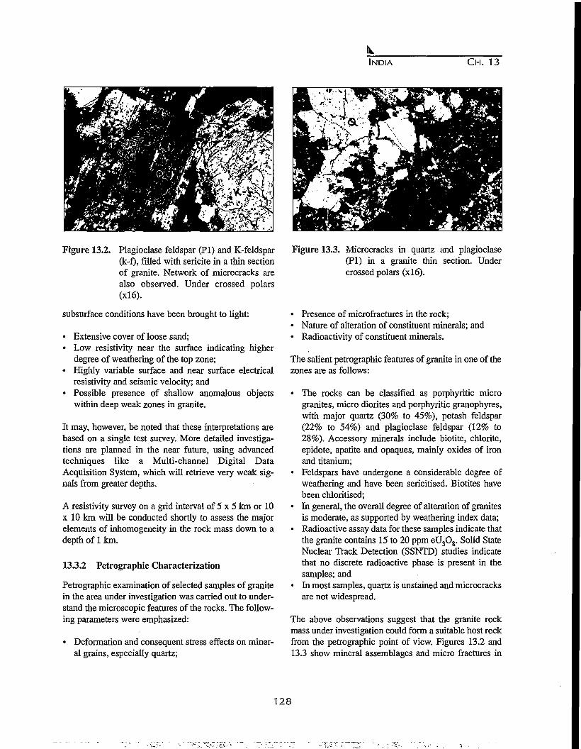
INDIA CH. 13
Figure 13.2. Plagioclase feldspar (PI) and K-feldspar(k-f), filled with sericite in a thin sectionof granite. Network of microcracks arealso observed. Under crossed polars
subsurface conditions have been brought to light:
• Extensive cover of loose sand;• Low resistivity near the surface indicating higher
degree of weathering of the top zone;• Highly variable surface and near surface electrical
resistivity and seismic velocity; and• Possible presence of shallow anomalous objects
within deep weak zones in granite.
It may, however, be noted that these interpretations arebased on a single test survey. More detailed investiga-tions are planned in the near future, using advancedtechniques like a Multi-channel Digital DataAcquisition System, which will retrieve very weak sig-nals from greater depths.
A resistivity survey on a grid interval of 5 x 5 km or 10x 10 km will be conducted shortly to assess the majorelements of inhomogeneity in the rock mass down to adepth of 1 km.
13.3.2 Petrographic Characterization
Petrographic examination of selected samples of granitein the area under investigation was carried out to under-stand the microscopic features of the rocks. The follow-ing parameters were emphasized:
• Deformation and consequent stress effects on miner-al grains, especially quartz;
Figure 13.3. Microcracks in quartz and plagioclase(PI) in a granite thin section. Undercrossed polars (xl6).
• Presence of microfractures in the rock;• Nature of alteration of constituent minerals; and• Radioactivity of constituent minerals.
The salient petrographic features of granite in one of thezones are as follows:
• The rocks can be classified as porphyritic microgranites, micro diorites and porphyritic granophyres,with major quartz (30% to 45%), potash feldspar(22% to 54%) and plagioclase feldspar (12% to28%). Accessory minerals include biotite, chlorite,epidote, apatite and opaques, mainly oxides of ironand titanium;
• Feldspars have undergone a considerable degree ofweathering and have been sericitised. Biotites havebeen chloritised;
• In general, the overall degree of alteration of granitesis moderate, as supported by weathering index data;
• Radioactive assay data for these samples indicate thatthe granite contains 15 to 20 ppm eU3Og. Solid StateNuclear Track Detection (SSNTD) studies indicatethat no discrete radioactive phase is present in thesamples; and
• In most samples, quartz is unstained and microcracksare not widespread.
The above observations suggest that the granite rockmass under investigation could form a suitable host rockfrom the petrographic point of view. Figures 13.2 and13.3 show mineral assemblages and micro fractures in
128
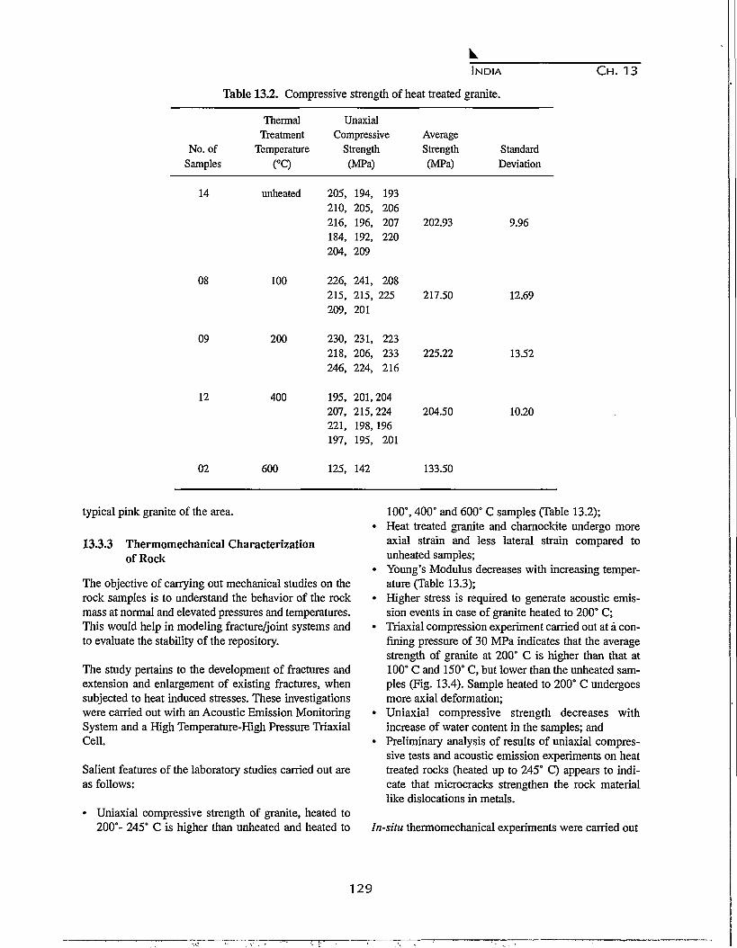
INDIA
Table 13.2. Compressive strength of heat treated granite.
C H . 13
No. ofSamples
14
08
09
12
02
ThermalTreatment
Temperature(°C)
unheated
100
200
400
600
UnaxialCompressive
Strength(MPa)
205, 194, 193210, 205, 206216, 196, 207184, 192, 220204, 209
226, 241, 208215, 215, 225209, 201
230, 231, 223218, 206, 233246, 224, 216
195, 201,204207, 215,224221, 198,196197, 195, 201
125, 142
AverageStrength(MPa)
202.93
217.50
225.22
204.50
133.50
StandardDeviation
9.96
12.69
13.52
10.20
typical pink granite of the area.
13.3.3 Thermomechanical Characterizationof Rock
The objective of carrying out mechanical studies on therock samples is to understand the behavior of the rockmass at normal and elevated pressures and temperatures.This would help in modeling fracture/joint systems andto evaluate the stability of the repository.
The study pertains to the development of fractures andextension and enlargement of existing fractures, whensubjected to heat induced stresses. These investigationswere carried out with an Acoustic Emission MonitoringSystem and a High Temperature-High Pressure TriaxialCell.
Salient features of the laboratory studies carried out areas follows:
• Uniaxial compressive strength of granite, heated to200°- 245° C is higher than unheated and heated to
100°, 400° and 600° C samples (Table 13.2);• Heat treated granite and charnockite undergo more
axial strain and less lateral strain compared tounheated samples;
• Young's Modulus decreases with increasing temper-ature (Table 13.3);
• Higher stress is required to generate acoustic emis-sion events in case of granite heated to 200° C;
• Triaxial compression experiment carried out at a con-fining pressure of 30 MPa indicates that the averagestrength of granite at 200° C is higher than that at100° C and 150° C, but lower than the unheated sam-ples (Fig. 13.4). Sample heated to 200° C undergoesmore axial deformation;
• Uniaxial compressive strength decreases withincrease of water content in the samples; and
• Preliminary analysis of results of uniaxial compres-sive tests and acoustic emission experiments on heattreated rocks (heated up to 245° C) appears to indi-cate that microcracks strengthen the rock materiallike dislocations in metals.
In-situ thermomechanical experiments were carried out
129
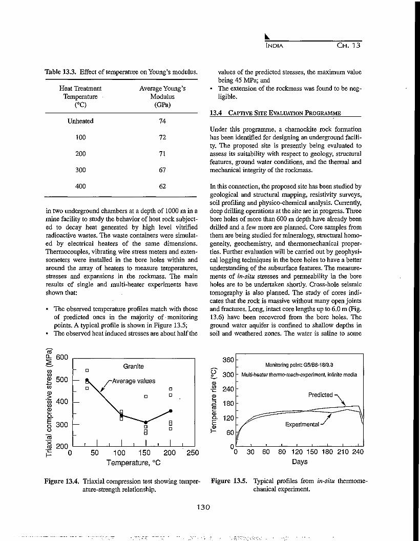
INDIA CH. 13
Table 13.3. Effect of temperature on Young's modulus.
Heat TreatmentTemperature
(°C)
Unheated
100
200
300
400
Average Young'sModulus
(GPa)
74
72
71
67
62
in two underground chambers at a depth of 1000 m in amine facility to study the behavior of host rock subject-ed to decay heat generated by high level vitrifiedradioactive wastes. The waste containers were simulat-ed by electrical heaters of the same dimensions.Thermocouples, vibrating wire stress meters and exten-someters were installed in the bore holes within andaround the array of heaters to measure temperatures,stresses and expansions in the rockmass. The mainresults of single and multi-heater experiments haveshown that:
• The observed temperature profiles match with thoseof predicted ones in the majority of monitoringpoints. A typical profile is shown in Figure 13.5;
• The observed heat induced stresses are about half the
values of the predicted stresses, the maximum valuebeing 45 MPa; and
• The extension of the rockmass was found to be neg-ligible.
13.4 CAPTIVE SITE EVALUATION PROGRAMME
Under this programme, a charnockite rock formationhas been identified for designing an underground facili-ty. The proposed site is presently being evaluated toassess its suitability with respect to geology, structuralfeatures, ground water conditions, and the thermal andmechanical integrity of the rockmass.
In this connection, the proposed site has been studied bygeological and structural mapping, resistivity surveys,soil profiling and physico-chemical analysis. Currently,deep drilling operations at the site are in progress. Threebore holes of more than 600 m depth have already beendrilled and a few more are planned. Core samples fromthem are being studied for mineralogy, structural homo-geneity, geochemistry, and thermomechanical proper-ties. Further evaluation will be carried out by geophysi-cal logging techniques in the bore holes to have a betterunderstanding of the subsurface features. The measure-ments of in-situ stresses and permeability in the boreholes are to be undertaken shortly. Cross-hole seismictomography is also planned. The study of cores indi-cates that the rock is massive without many open jointsand fractures. Long, intact core lengths up to 6.0 m (Fig.13.6) have been recovered from the bore holes. Theground water aquifer is confined to shallow depths insoil and weathered zones. The water is saline to some
9= 600
toto
500 -co
8 400
Q.
I 300o
"TO"x
200
Granite
— 8v ^Average values
aB
, 1 , 1 , 1 ,
Da
B
1 ,50 100 150 200 250
Temperature, °C
o
360
300
Monitoring point: G5/B8-18/3.3
- Multi-heater thermo-mech-experiment, infinite media
0 30 60 80 120 150 180 210 240
Days
Figure 13.4. Triaxial compression test showing temper- Figure 13.5. Typical profiles from in-situ thermome-ature-strength relationship. chanical experiment.
130

INDIA CH. 13
Figure 13.6. Intact long borehole core samples from charnockite formation.
extent, and the rock has good sorption properties.
13.5 CONCLUSION
The Indian programme of siting and host rock charac-terization for a geological repository in granite compris-
es selection of a site by the method of narrowing downthe choice from larger areas to a specific site, on the onehand, and directly characterizing a known potential hostrock formation within the captive area of a nuclear site,on the other.
131

132

CHAPTER 14
CRITICAL DATA REQUIRED TO POTENTIALLY INVESTIGATE GENTING
ISLAND AS HIGH-LEVEL RADIOACTIVE WASTE REPOSITORY SITE FACILITY
IN INDONESIA
Y. U. Imardjoko, H. B. Santosa, Sunarno, N. Prabaningrum, A. Muharini,E. Wijayanti, and M. Adiartsi
Department of Nuclear Engineering, Gadjah Mada University, Ji. Grafika 2, Sekip,Yogyakarta, DIY. 55281, Indonesia
14.1 INTRODUCTION
The Indonesian archipelago is one of the regions in theworld that has active volcanisms. There are 129 activevolcanoes in the region. The Indonesian archipelago isdeveloping in response to the complex interactionbetween the southward moving Eurasian plate, thenorthward moving Indian-Australian plate and the west-ward-moving Pacific plate (Fig. 14.1). The Java trenchand Timor Trough represent the major area of collisionbetween Eurasian and Indian-Australian plates. TheSorong fault indicates the area of interaction betweenthe Pacific and Indian-Australian plate1.
Indonesia has been actively planning to build severalNPPs in the near future, despite the concerns about the-existing volcanism. The operation of these NPPs willgenerate waste, namely high-level radioactive wastes(HLRW). Some islands in the country have been inves-tigated and selected as potential HLRW repository sites.
Genting island is one of these islands with a potentialsite for a HLRW repository site facility. A wet environ-ment repository concept must be developed since theproposed island is an ocean-island, and the groundwatertable is shallow such that the wastes will have to beemplaced in the saturated zone.
Indian AustralianPlate
Figure 14.1. Plate boundaries in the Indonesian Archipelago.
133

INDONESIA C H . 14
p
r-. Genting
B l s l a n d
J A V A S E A
Figure 14.2. Map of Karimunjawa Archipelago show-ing location of Genting Island. The long-dashed line shows the location where thewater depth is 20 m.
14.2 GENERAL DESCRIPTION OF THE ISLAND
Genting island is a small island situated on the northside of Java island on the Eurasian plate (Fig. 14.2)2.The distance from the Java trench is approximately 400km. This island is nearly uninhabited and there is nopotential economic activity. The groundwater level atGenting Island is considered shallow, and it is influ-enced by changes in sea level and the rate of rainfall(Fig. 14.3)2.
14.2.1 The Lithology of the Area
The top layer (thickness ±1.5 - 3.5 m) of soil is mainlyalluvium consisting of pebble, gravel, clay, coral lime-stone and coarse grained rocks. Below this layer isbasalt (thickness ±24 - 35 m) consisting of basaltic lavaor alkaline basalt, classified as a strong rock (approxi-mate strength is 1550.36 kg/m2 in compression)2. Itsstrength and the interlocking of fracture blocks can limitdisplacement along fractures. The diffusion time ofradionuclides along the rock fractures can be delayed, so
Basaft outcrop
J A V A S E A
Figure 14.3. Map of groundwater levels for southerntip of Genting Island in meters above sealevel. The solid lines indicate water levelsthat are above the land surface, and thedashed lines indicate levels that are belowthe land surface.
that it will eventually take longer for the radionuclidesto reach the accessible environment (AE). The depth togroundwater is approximately 103 m. The permeabilitymeasurements of Genting Island are shown in Table14.1.2
Table 14.1.Permeability measurements for GentingIsland.
Coefficient of Permeability (m/s)
1.82 x 10"6
1.75 x 10⁻⁶
1.26 x lO"7
5.55 x 10"6
4.79 x 10"6
Type of Rocks
Soil andBasaltBasaltBasaltBasalt
The water chemistry of Genting Island is such that theconcentrations of Mg2+, Na+, and Cl" are rather high inthe coastal area. The content of HCO3' tends to increaseon the southern side of the Island. The existence of
134

INDONESIA CH. 14
HCO3' in the groundwater is due to the influence ofdecomposed plants and swamp materials.
The southern side of the Genting Island is primarily avolcanic cone region. The highest point of this area is40.5 m above mean sea level, and the lowest point isabout 5.0 m above mean sea level.
From geotechnical investigations, the unconfined com-pression strength is 360.86 kg/cm2. The mean value ofPoissons ratio is 0.31. The mean value of the rock den-sity is 2.797 g/cm3, and the mean value of cohesivenessis 57.87 kg/cm2.
14.2.2 Near-Field Conditions
In the model, pH, water contact mode, and temperatureare included, where pH (at the 50 m depth in an experi-mental borehole), varies from 7.7 to 6.8. The average pHis 7.25, which can be considered neutral. The water con-tact mode, in the saturated zone can be thought of aszero velocity, which indicates diffusive transport,because Genting Island is an ocean-island3'4"5.
14.3 DESIGN OF THE REPOSITORY SITE
The proposed design for the HLRW repository site atthe southern tip of Genting Island is divided into twoareas or rings. The inner ring (called the high-tempera-ture ring) that contains a group of waste packages with-an areal power density of approximately 100 kw/acre,which includes 75% of the waste packages. The outerring contains a group of waste packages with an arealpower density of approximately 30 kw/acre, whichincludes 25% of the waste packages, and represents theambient-temperature ring3.
14.4 PATHWAY PARAMETERS
For an ocean-island repository that is sited below thegroundwater table, the most important pathway forradionuclide releases is through the groundwater. Theradionuclides released through the rock will eventuallyreach the groundwater. In the groundwater, the radionu-clides will travel in a dffusive manner to the AE.Therefore, the groundwater is expected to be the prima-ry agent affecting the performance of the Genting Islandrepository. In addition to being the transport mechanismfor the radionuclides, the groundwater will also corrodethe waste containers when it comes in contact with thecontainers6. The shallow groundwater is assumed toexist under reducing conditions. Consequently, it is also
necessary to consider solubility under reducing condi-tions.
In regard to gaseous flow and transport, this study sug-gests that C-14 will not be released in any significantquantity.3-4-5 However a more accurate analysis shouldbe conducted. The gas flows are driven by heat and inturn affect waste package temperatures. A coupled tran-sient model of heat transfer and gas flow employing arelatively fine grid will be required.
The ocean dilution factor plays a very important role inreducing the concentration of radionuclides released tothe AE. Their concentrations become essentially negli-gible when this factor is incorporated in the analyses.Therefore, it is necessary to employ a more accuratemodel to calculate the dilution factor7. However, theocean will not be considered as the source of drinkingwater; only the biota in the ocean should be analyzed asthe potential transport pathway in future studies5.
14.5 SUMMARY AND CONCLUSIONS
In addition to the problem of pathways for radionuclidereleases, earthquakes play an important role in therepository integrity. When the rate of occurrence wasselected to be lxlO"7, no effects are shown in theresults3. But, when the rate of occurrence was taken tobe lxlO"2, some significant effects were seen. Therefore,further study regarding seismic analyses of the site mustbe undertaken8.
Understanding groundwater flow characteristics isessential when attempting to predict repository perfor-mance more accurately9. These characteristics arerequired, especially parameters of the directions of flowand the flow rate. Furthemore, if there are releases ofradiation in the near-field environment, the possibledegradation of the rocks in the buffer zone should alsobe further investigated10.
REFERENCES
1. Katili J.A., Magmatic affinities of volcanic rocks ofUngaran, Central Java, Journal Geologi Indonesia,The Journal of the Indonesian Association ofGeologists, Volume 60, Jakarta, Indonesia, 1989.
2. Faculty of Mineral Technology, Institute ofTechnology - Bandung, Further Geological andHydrogeological Investigation at Genting Island asProposed Location for Permanent Radioactive Waste
135
INDONESIA CH. 14
Repository, National Atomic Energy Agency(BATAN), Jakarta, Indonesia, 1990.
3. Imardjoko Y.U., Total system performance assess-ment of the proposed high level radioactive wasterepository at Genting Island, Karimunjawa,Indonesia, Ph.D. Dissertation, Iowa State University,Ames, LA, July, 1995.
4. Imardjoko Y.U., D.B. Bullen, and S. Yatim,Performance assessment modeling of the proposedhigh-level radioactive waste disposal facility atGenting Island, Karimunjawa, Indonesia, JournalManusia dan Lingkungan, PPLH-UGM, Indonesia,December 1995.
5. Imardjoko Y.U., D.B. Bullen, and S. Yatim,Performance assessment modeling of the proposedGenting Island repository facility, Proceedings,International High Level Radioactive WasteManagement Conference, ANS-ASCE, Las Vegas,pp. 172-175, NV, April, 1996.
6. EPRI, Geological disposal of nuclear waste,Electrical Power Research Institute Journal, PaloAlto, CA, May, 1982.
7. Forsberg C.W., An ocean-island geologic repository -
A second - generation option for disposal of spentfuel and high - level waste, Nuclear Technology, Vol.101, January, 1993.
8. Wallmann P.C., I. Miller, and R. Kossik, Assessmentof volcanic and tectonic hazards to high levelradioactive waste repositories, High LevelRadioactive Waste Management - Proceedings of theFourth Annual International Conference, Las Vegas,Nevada, Vol. 1, pp.188-195, April 26 - 30,1993, ANS,La Grange Park, IL, 1993.
9. Ahoka H., and F. Ky, Roles of fracture zones in con-trolling hydraulic head and groundwater flow - expe-rience from site characterization program in Finland,High Level Radioactive Waste Management -Proceedings of the Fourth Annual InternationalConference, Las Vegas, Nevada, Vol. 1, pp. 431-436,April 26 - 30,1993, ANS, La Grange Park, EL, 1993.
lO.Dershowitz, W.S., P.C. Walimann, T.W. Doe, and J.Geier, Discrete feature modeling at the Stripa mine inSweden: Significance for hydrologic modeling offractured rock masses, High Level Radioactive WasteManagement - Proceedings of the Fourth AnnualInternational Conference, Las Vegas, Nevada, Vol. 1,pp. 443-450, April 26 -30,1993, ANS, La GrangePark, IL, 1993.
136

CHAPTER 15
GEOLOGICAL DISPOSAL DEEP UNDERGROUNDA STUDY OF THE JAPANESE GEOLOGICAL ENVIRONMENT AND ITS
STABILITY
Aiji Yamato
Power Reactor and Nuclear Fuel Development Corporation,1-9-13 Akasaka, Minato-ku,Tokyo 107 Japan
15.1 INTRODUCTION
In order to demonstrate the scientific and technologicalsafety of geological disposal in Japan, it is important tomake an accurate assessment of the geological environ-ment and to incorporate this knowledge into the perfor-mance assessment and R & D of disposal technologybased on a realistic model of this environment. At pre-sent, surveys and studies are being conducted withoutspecification of regions or rock types.
Geoscientific knowledge to date indicates that the geo-logical environment deep underground is characterizedby generic qualities found in all regions and other qual-ities, which are peculiar to a specific region. For aneffective assessment of the Japanese geological environ-ment, it is important to make a systematic collection ofdata on specific and generic regional characteristics thatare relevant to geological disposal.
Based on their origin, rocks can be divided roughly intothree groups, igneous, metamorphic, and sedimentary.Within these groups, various subdivisions are catego-rized by mineral/chemical components, grain size andtexture, etc. However, from the viewpoint of groundwa-ter flow and mass transport, which are pertinent to theperformance assessment of geological disposal, the pre-sent characteristics of rocks have a greater significancethan those at the time of their formation. These charac-teristics include physical and chemical qualities, thehydraulic structure of rocks deep underground, and thechemical properties of rock groundwater systems, suchas the extent and rate of nuclide sorption. Based on thisapproach, it is possible to classify the rock formations inJapan into two groups: crystalline rocks (fracturedmedia) and sedimentary rocks (porous media). Graniticand sedimentary rocks of the Neogene are widely dis-tributed throughout Japan and can be taken as being rep-
resentative of the two groups defined above.
The Power Reactor and Nuclear Fuel DevelopmentCorporation (PNC) is promoting geological researchwith emphasis on present-day conditions. A newresearch division has been established to perform sur-veys and studies of the deep geological environment asa basis for research and development (R & D) programson geological disposal.
This report outlines the R & D activities conducted sofar, as well as future plans.
15.2 PURPOSE AND PROCEDURES OF RESEARCH AND
DEVELOPMENT PROGRAMS
The purpose of geological research is to characterize thegeological environment of Japan from the point of viewof geological disposal, to construct models of geologicalstructures and groundwater flow, to systematize avail-able data, to make accurate and efficient assessments ofthe geological environment, and to develop practicaltechnologies for analysis and evaluation purposes. Themodels and data obtained through such studies areapplied in performance assessment and R & D pro-grams.
Data on the flow and geochemical characteristics ofgroundwater, as well as on mass transport, are importantin assessing the performance of the near-field and far-field in a geological disposal system. In near-field stud-ies, it is essential to obtain accurate data on thehydraulic and geochemical characteristics of thebedrock adjacent to the engineered barrier system,including the excavation disturbed zone. For the far-field, on the other hand, data are required on the ground-water flow and mass transport characteristics of fractureand alteration zones over a wide region and on hydraulic
137

JAPAN CH. 15
and chemical properties at the boundary between sea-water and freshwater in coastal regions.
Since data on the deep geological environment must beas precise and reliable as possible from the viewpoint ofgeological disposal, it is therefore necessary to developand improve the technologies used in surveys and mea-surements to ensure more efficient and detailed dataacquisition. Equipment is being developed that willallow surveys of bedrock with very low permeability orunder the high pressure and temperature conditions pre-vailing deep underground in order to advance studies ofhydraulic and geochemical characteristics. At the sametime, attention is being given to methods which are dis-turbance-free, i.e. they do not cause damage or upset thenatural condition of the rock. For this purpose, effortsare being directed toward improving techniques of phys-ical and drilling surveys as well as integrating varioussurvey techniques.
A given geological environment is considered stable forthe purpose of geological disposal if the formation,selected as being most appropriate, can maintain itsrequired role for safe disposal despite the potential forchanges in the environment. Li order to assess the sta-bility of a geological formation, it is necessary to ascer-tain potential changes in the environment brought aboutby various phenomena, as well as the extent of thesechanges. Predictive studies require analysis of datarelated to the occurrence and regularity of natural phe-nomena (extent, region, regularity, mechanism of occur-rence, etc.) and identification of a pattern of regularity,if any.
Studies on the geological environment include compil-ing accumulated data and the most recent findings inrelated fields of science and engineering and applyingthe results of geological R & D at the Tono andKamaishi mines. Cooperative studies with other coun-tries advanced in the field of geological disposal alsocontribute to establishing investigation techniques andprocedures for performance assessment.
15.3 CHARACTERISTICS OF GEOLOGICAL
ENVIRONMENT AND CURRENT STATE OF
KNOWLEDGE
Deep geological formations are generally characterizedby extremely slow groundwater flow and a reducingchemical environment of neutral to slightly alkalinenature. As a result, it is unlikely that radionuclides with-in the waste will be significantly leached out; even if the
waste matrix does dissolve, the likelihood is that theescaping nuclides will either be sorbed onto clay miner-als in the adjacent bedrock and fractures or will be pre-cipitated. It is expected, therefore, that the migration ofradionuclides will be even slower than the rate ofgroundwater flow.
Tests conducted on sedimentary rocks in the Tonoregion of Gifu Prefecture indicated the hydraulic con-ductivity to be approximately 10'8 m/s to 10'10 m/s andthe oxidation-reduction potential to be low at -300 mVfor groundwater at 160 m depth. In the case of the Tonouranium deposit, one characteristic of the geologicalenvironment which is evident is that no major migrationof uranium has occurred in the past 105 years.
The deep geosphere also has the characteristic, com-pared to the ground surface, of not being readily affect-ed by natural phenomena such as earthquakes, glacia-tion, weathering and erosion, or by human activities.
Earthquake observation in the gallery of the KamaishiMine indicated that the ground acceleration rate mea-sured several hundred meters underground was approx-imately half that measured at the ground surface. Long-term observation of the pore pressure and chemicalproperties of groundwater has revealed no major changeso far. Temporary changes are recorded at the time of anearthquake, but these are within the range of seasonalfluctuations (Shimizu, et. al., in press).
One of the natural phenomena considered to have apotential influence on the stability of the geologicalenvironment is the fault activity assumed to haveoccurred during the Quaternary. A survey of fault distri-butions indicates that there is a wide region without anyfaulting and, even within regions where numerous faultsare found, there are blocks of rock where no faults exist.Igneous activity occurring in the Japanese archipelago islikely to be related to the location and depth of platesubduction in the vicinity, but there has been no majorchange in the past 12 million years. Periods of glaciationand sea-level changes are global phenomena which havebeen repeating in cycles of approximately 10s years forthe past 7 x 10⁵ years. An accurate understanding ofregional characteristics, regularities and cycles in natur-al phenomena, allows the stability of the geologicalenvironment to be assessed reliably.
15.4 PRESENT RESEARCH AND DEVELOPMENT
Of the geological research and development currently
138

JAPAN C H . 15
underway, a report is presented here on the present stud-ies of geological formations and on R & D proceduresrelating to assessing long-term safety.
15.4.1 Investigations Conducted at and Aroundthe Tono Mine
The Tono Mine is a uranium mine situated in the Tonoregion of Gifu Prefecture. The region around the TonoMine is formed basically of granite, covered with
Neogene sedimentary rock (Fig. 15.1). In this region, anenormous amount of geological information is beingaccumulated through uranium prospecting and academ-ic research. The shaft and gallery leading to the mineallow access to sedimentary rocks, including uraniumdeposits, over one hundred meters underground.Surveys conducted in this region include the hydrologyand geochemistry of groundwater, mass transport bygroundwater and the effect of excavating galleries on thegeological environment (Yusa, et. al., 1992).
+ 1 2 3 4 5km
LEGEND
Uranium Deposit
Fautl
| | Alluvium
''.•.I Selo Group
Mlzunaml GroupGranitic RockPalaoozolc—MosozolcSedimentary Rock
0(m)0 500 (m)1 i i i i I
Figure 15.1. Geological and Location Maps of the Tono Mine Region.
139

JAPAN CH. 15
The hydrological research being conducted at presentincludes accumulation of reliable hydraulic data downto a depth of 500 m below ground surface, constructionof a hydrogeological model based on survey results,consideration of methods for predicting groundwaterflow and evaluation and verification of the groundwaterflow model (Fig. 15.2). The results of permeabilityinvestigations conducted on Neogene sedimentary rocksand granites in the Tono region indicated that the
A
EL 314i
hydraulic conductivity of sedimentary rocks is higherfor coarse-grained formations. The value was approxi-mately on the order of 10'8 m/s for medium to coarsesandstones. The hydraulic conductivity of granites isclassified into two categories of high permeability (10"5
to 10"6 m/s) measured in the vicinity of open fracturesand low permeability (10'8 to 10'11 m/s) measured in theunfractured rock mass and in fracture zones filled withclay minerals.
SN — 4
1 X I0-»<05 X IO«S • < 11 X \O-*£ o < S5 X IO-'S • < 11 X IO-'Sa<55X IO-«S*<I
* < 5
XXXXXX
10-5io-«io-«IO- 'IO-Iio-«
(cm/sec)
B Surface soil
Unconsolidatedsediment
(Seto Group)
Sandstone
Sandstone • TuffSandstoneWeathering
Granite
Granite
• N e w shaft• Existing shaft
Sandstone • Mudstone
Tuff
Sandstone
YWeathering GraniteJy ' Conglomerate
Weathering Granite
Granite
Fault with Fault clay
Figure 15.2 A - Hydraulic conductivity distribution, and B - hydrogeological model for the Tono region.
140

JAPAN C H . 15
Depth0 m
30m
150nr
SetoGroup
MizunamiGroup
Aquielude
MizunamiGroup
GraniticRock
i i i i
O
O
o
o
o
o
1 1 1 110
o—
5 0 8 10
pH Hexadiagram Concentration of Trit ium
Figure 15.3. Groundwater pH, chemistry and tritium concentration for the Tono region (Major solution compo-nents are presented on a hexadiagram.
For a three-dimensional analysis of groundwater flowtaking the example of the Tono region, piezometricheads are almost hydrostatic except near the surface.Thehydraulic gradient is below 0.04 for areas deeper than500 m underground. The procedure for future researchon groundwater flow will be to obtain hydraulic data fordepths down to 1,000 m underground, to improve meth-ods for analyzing groundwater flow and to develop suit-able investigation methods for a given region.
Geochemical studies aim to determine the age and ori-gin of groundwater and the distribution of geochemicalcharacteristics and to confirm the relevance of the modelof the geochemical evolution of groundwater. For thispurpose, sampling and analysis of groundwaters fromboreholes is being carried out. Groundwaters in sedi-mentary rocks are mostly the Na-HCO3 type, and the pHvalue moves from neutral to alkaline as depth increases(Fig 15.3). A comparative analysis of oxygen and hydro-gen stable isotopes confirms the theory of precipitationas the origin of the groundwater.
Radiocarbon dating reveals the groundwater at the baseof the sedimentary formations to be at least in excess of104 years old. The figures for pH, redox potential andconcentration of chemical components obtained from ageochemical equilibrium model and from actual mea-
surements in the region agree well with one another.Future tasks are to accumulate geochemical data downto a depth of 1,000 m and to study the geochemical evo-lution of deep groundwaters, also for granitic rocks(Yamakawa, 1991; Yoshida, et. al., 1994).
To examine solute migration in the deep geologicalenvironment, the Tono uranium deposit and its sur-rounding area are being studied as a natural analogue formigration and immobilization of material within a geo-logical formation. Studies are underway on the environ-mental conditions for generation and preservation ofuranium deposits and on the migration and retardationof natural series nuclides by groundwater flow. Studiesso far show that uranium is immobilized in a reducingenvironment, that the migration and concentration ofuranium depends not only on the mineralogy and chem-istry of the rocks but also on groundwater flow, and thatthe uranium found in the ore deposit has not migratedsignificantly over the past 10s years. Future studiesshould clarify the route of groundwater flow and its rela-tionship with migration of natural series nuclides, andalso quantify migration and advance modeling of sorp-tion phenomena.
To ascertain the influence of excavation on the rock for-mations surrounding a gallery, a series of studies are
141

JAPAN CH. 15
15m 15m
KS-1 KS-1
-5KS-2
velocity(kmfeec)
• SoureoO Receiver -5
KS-2
10
(a) Before Excavation of Experimental Gallery
25 (ra) 10 15
(b) Before and After Excavation of Experimental Gallery
25 (m)
Figure 15.4. Experiment on excavation effects at the Tono Mine.
being conducted in which the original condition of thebedrock is assessed before excavation, followed by pre-diction of the effect of excavation and, finally, by actualmeasurement of the effects of excavation (Fig. 15.4). Ina study of excavation effects, a shaft with a 6 m innerdiameter and 150 m deep has been observed for approx-imately the past four years. Observations indicate thatthe "excavation disturbed zone" created by blasting thebedrock extended about 1 m from the shaft wall, whilechanges in pore pressure extended to a radius of approx-imately 100 m from the shaft. The next step is to ascer-tain the effects on different rock types and of varyingmethods of excavation, as well as to improve the tech-niques employed in measurement and analysis. It is alsonecessary to continue monitoring over an extensive peri-od in order to understand the long-term impact onbedrock deformation and hydrology, etc (Sato, et. al.,1995).
15.4.2 Surveys Conducted at Kamaishi Mine
The Kamaishi Mine is an iron and copper mine withgranite as the parent rock; it is situated near KamaishiCity in Iwate Prefecture. PNC has been conductinginvestigations in the Kurihashi granitic diorite since1988, in a gallery located 550 m above sea level(approximately 300 m below ground surface). In 1993,a second phase was launched for a five-year period in agallery 250 m above sea level (approximately 700 mbelow ground surface). The research includes assess-ment of geological characteristics deep underground,appraisal of the extent of the excavation disturbed zonein the bedrock, hydraulic and migration tests in crys-
talline rock, testing of engineered barriers and seismicsurveys (Fig. 15.5) (Takeda and Osawa, 1993).
In the first five years, the aim was to collect data on thedistribution of various characteristics and phenomenaoccurring in the geological environment. At the sametime, the appropriateness of investigation techniqueswas also tested. Surveys conducted included investiga-tions of fractures in gallery walls and boreholes, physi-cal surveys to ascertain the distribution of fractures,hydrogeological research to assess the permeability ofthe bedrock, groundwater flow and its modeling, geo-chemical research to determine the origin, age, chemicalevolution, etc., of groundwater, bedrock dynamics totest the effects of gallery excavation, seismic research,and research on engineered barriers.
These studies contribute to improving the understandingof physical properties such as the strength of theKurihashi granitic diorite, initial stress conditions, thepermeability of the bedrock, channeling phenomenawhereby groundwater tends to flow along distinct path-ways within a fracture, geochemical properties ofgroundwater deep underground and in-situ swelling ofbentonite clay as a backfill in bedrock. Studies conduct-ed on the effect of gallery excavation on the geologicalenvironment showed that any change in the permeabili-ty and deformation of the bedrock occurred within aradius of 1 m from the gallery wall.
Through these studies, it is possible to ascertain theeffectiveness of techniques for modeling groundwaterflow near the gallery and the deformation behavior of
142
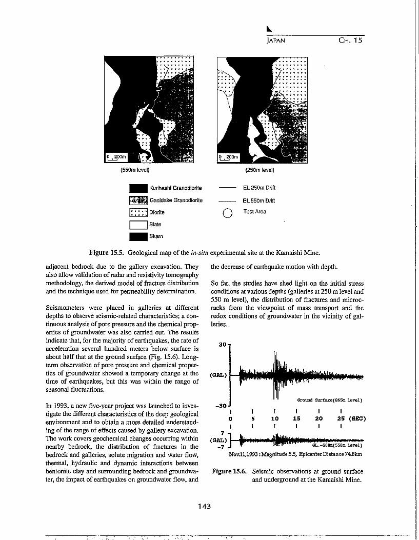
JAPAN CH. 15
IP . 200m
(550m level) (250m level)
Kurihashi Granodiorite
Ganidake Granodiorite
Diorite
Slate
Skarn
o
EL 250m Drift
EL 550m Drift
Test Area
Figure 15.5. Geological map of the in-situ experimental site at the Kamaishi Mine.
adjacent bedrock due to the gallery excavation. Theyalso allow validation of radar and resistivity tomographymethodology, the derived model of fracture distributionand the technique used for permeability determination.
Seismometers were placed in galleries at differentdepths to observe seismic-related characteristics; a con-tinuous analysis of pore pressure and the chemical prop-erties of groundwater was also carried out. The resultsindicate that, for the majority of earthquakes, the rate ofacceleration several hundred meters below surface isabout half that at the ground surface (Fig. 15.6). Long-term observation of pore pressure and chemical proper-ties of groundwater showed a temporary change at thetime of earthquakes, but this was within the range ofseasonal fluctuations.
In 1993, a new five-year project was launched to inves-tigate the different characteristics of the deep geologicalenvironment and to obtain a more detailed understand-ing of the range of effects caused by gallery excavation.The work covers geochemical changes occurring withinnearby bedrock, the distribution of fractures in thebedrock and galleries, solute migration and water flow,thermal, hydraulic and dynamic interactions betweenbentonite clay and surrounding bedrock and groundwa-ter, the impact of earthquakes on groundwater flow, and
the decrease of earthquake motion with depth.
So far, the studies have shed light on the initial stressconditions at various depths (galleries at 250 m level and550 m level), the distribution of fractures and microc-racks from the viewpoint of mass transport and theredox conditions of groundwater in the vicinity of gal-leries.
30
(GflL)
- 3 0Grounl Surface(865m level)
7(GAL)
- 7
IO1
1 i
j i
i51
r
i101
iWr'
1151
1 120 251 1
GL.-300m(550m
(SEC)
level)Nov.11,1993: Magnitude 55, Epicenter Distance 748km
Figure 15.6. Seismic observations at ground surfaceand underground at the Kamaishi Mine.
143

JAPAN CH. 15
15.4.3 Development of Techniques forInvestigating Deep Geological Environment
In order to make quantitative measurements of hydraulicparameters deep underground, a hydraulic measurementdevice designed for conditions of slow water pressurebuild-up has been developed for application in low per-meability bedrock. An in-situ measurement device hasalready been constructed for use at depths down to 500m and in the order of 10"11 m/s for the hydraulic con-ductivity. Other equipment developed allows a continu-ous in-situ measurement of parameters such as redoxpotential, pH and dissolved oxygen concentration. Withthe development of a packer-system in a pressuredgroundwater sampling device, which is gas-tight, it isnow possible to obtain groundwater samples withoutdisturbing their original condition within the rock for-mation. A new device was completed in 1994; it can beused down to a depth of 1,000 m and is in the process ofbeing tested. Efforts have also been devoted to develop-ing an evaporranspiration device for measuring the dis-tribution of influx volumes from gallery walls and asinusoidal, crosshole experimental device for use in asingle fracture near the gallery wall.
When gathering data in the deep geological environ-ment, it is desirable to do so without disturbing the nat-ural conditions, so as to fully preserve the fractureswithin the bedrock, the geological structure andhydraulic characteristics. As a consequence, the devel-opment and testing of resistivity and seismic tomogra-phy are presently underway. Furthermore, a radar tech-nique is being developed, which uses multiple boreholesin order to determine precise fracture zone locations andtheir extent.
It is also important to improve surface-based methodsfor predicting conditions in the deep geological environ-ment; the results can then be confirmed using dataobtained after excavation of galleries. Research in thisarea is being carried out jointly by SKB and PNC.
15.4.4 Research on the Long-Term Stability ofthe Geological Environment
In the first technological report (PNC's Heisei 3Report), natural phenomena with a potential influenceon the geological environment were summarized, sug-gesting the existence of regionality and regularity inthese phenomena. They include earthquake and faultactivity, volcanic activity, uplift and denudation, climat-ic fluctuation and sea-level change. In view of the
importance of understanding and predicting the influ-ence of these phenomena on the geological environ-ment, surveys are being conducted of relevant literaturepublished in Japan and abroad (Shimizu, et. al., 1992).
Literature surveys and analyses are performed to firstclarify the history of individual natural phenomena. Thenext step is to conduct research on the nature and scaleof the impact of such phenomena on the geological envi-ronment and to establish a method for defining a realis-tic range of fluctuation for the predicted influence ofthese phenomena.
Regarding fault activity, attention is focused on the pos-sibility of the formation of new faults, by observing thefluctuations in time and space and the locations of faultactivity. A method for ascertaining the hydraulic andgeochemical fluctuations in groundwater is being con-sidered in order to provide an understanding of the rangeof influence of fault activity on the nearby geologicalenvironment.
To predict the range of variation in uplift and subsi-dence, it is necessary to have accurate knowledge of pastdata and an understanding of crustal movements inJapan; a systematic compilation is therefore being madeof relevant geomorphological data. To estimate topo-graphic and decreases in the thickness of geological for-mations, which accompany uplift and subsidence, mod-eling of denudation and future topographic changes isalso necessary.
As for volcanic activity, the characteristics and regional-ity of Quaternary volcanic activity should be ascer-tained; the locations of activity as well as the relation-ship between geological structure, stress fields and platedistribution should also be clarified in order to substan-tiate the assumption that the region of volcanic activitywill not change in the future. Studies should be able todetermine the range and scale of thermal impact and itsinfluence on the geochemical characteristics and flow ofgroundwater.
Studies should be carried out to assess the scale and reg-ularity of climatic and sea-level changes on a globalscale.
15.5 CONCLUSIONS
Any discussion of the geological environment of Japanwithin the context of geological disposal programsrequires the development of transparent and logical ana-
144

JAPAN CH. 15
lytical methods and a systematic accumulation of reli-able data. It is also important to make maximum use ofexisting information. Advances in a new field ofresearch and development, as in the case of this report,should be pursued with the support of public under-standing and participation, from the beginning, ofexperts from all related areas of study; this ensurestransparency and steady progress. By way of recogniz-ing the importance of obtaining the consensus of expertsfrom various fields on the overall progress and directionof R & D programs, as well as on individual studies,projects are pursued with constant referral to variouscommissions.
Regarding sites for research on the deep geologicalenvironment, the Atomic Energy Commission of Japanhas indicated the desirability of having multiple facili-ties in view of the wide range of geological features inJapan; this is stated in the "Long-Term Program forResearch, Development and Utilization of NuclearEnergy." There is also a clear distinction between plansfor an underground research facility and plans for geo-logical disposal. PNC is also aware of the importance ofcarrying out research, not only in existing galleries, butalso in geological environments with undisturbed condi-tions. It is also important to verify predictive surveysmade from the ground surface, following actual excava-tion of galleries. A research facility which would allowsuch activities to be pursued is of utmost importance andPNC is devoting considerable efforts toward construc-tion of such a facility as soon as possible.
REFERENCES
Sato, T., K.Sugihara, and H. Matsui, Geoscientific stud-
ies at the Tono mine and the Kamaishi mine in Japan,Proc. of 8th International Congress on Rock mechan-ics, Vol.1, pp. 47-51,1995.
Shimizu, H., K. Ishimaru, K. Furuya, and Y. Yusa,Natural processes and events relevant to long-termstability of geological environment in Japan, Proc. ofthe Workshop WC-1 "Waste Disposal and GeologyScientific Perspectives", 29th Internatioal GeologicalCongress, pp.381-394,1992.
Shimizu, I., H. Osawa, T. Seo, S. Yasuike, and S. Sasaki,Earthquake related ground motion and groundwaterpressure change at the Kamaishi Mine, EngineeringGeology Special Publication (in press, 1996).
Takeda, S. and H. Osawa, Current status and future pro-gram of in-situ experiments of Kamaishi, Japan,Proc. International Symposium on In-SituExperiments of Kamaishi, Japan, Nov.11-12,1993.
Yamakawa, M., Geochemical behavior of natural urani-um-series nuclides in geological formation, Proc.Third International Symposium on AdvancedNuclear Energy, pp.150-158,1991.
Yoshida, K. et al., Data Compilation of GeoscientificStudies of Tono Uranium Deposits, Central Japan,PNC TN 7410 94-15,1994.
Yusa, Y., K. Ishimaru, K. Ota, and K. Umeda,Geological and geochemical indicators of paleohy-drogeology in Tono uranium deposits, Japan, Proc.Workshop in Paleohydrogeological Methods andTheir Applications for Radioactive Waste Disposal,OECD/NEA, Paris, 9-10 Nov., 1992.
145

146

CHAPTER 16
GENERIC PERFORMANCE AND ENVIRONMENTAL ASSESSMENT OF ARADIOACTIVE WASTE REPOSITORY IN KOREA
Chang Lak Kim,, Myung Chan Lee and Jang Soo Nam
Nuclear Environment Management Center, Taejon, Korea
Abstract. The Nuclear Environment Management Center (NEMAC), a subsidiary of the Korea Atomic EnergyResearch Institute (KAERI), has conducted a performance and environmental assessment of the proposed Koreanradioactive waste repository. In this paper, a description is provided of the performance and environmental assess-ment of a generic Korean radioactive waste repository. A description is given of the various data needed in post-clo-sure performance assessment calculations. The data are divided into four major categories: inventory and design data,chemical data, hydrogeological data, and biosphere data. The results suggest that a generic performance assessmentof the conceptual repository may be acceptable when measured against the regulatory criteria. The results indicate,however, that the performance will be strongly dependent on the geology and hydrogeology of the repository loca-tion, and it should be noted that the assessment was carried out on the basis of a limited understanding of the site-specific characteristics. It will be necessary to obtain site-specific data at the intended repository location in order toenable a more detailed assessment to be undertaken. This preliminary assessment of the conceptual repository pro-vides a firm foundation for future site-specific assessment activities.
16.1 INTRODUCTION
The radioactive waste management program in Koreadates back to mid-eighties when KAERI perceived,from prior studies, the necessity for a national programfor a comprehensive and systematic management ofradioactive wastes including spent fuel arising from thiscountry's ambitious nuclear power plant program. Therecommendation therefrom was taken in considerationby the Korea Atomic Energy Commission which made adecision at its 221st meeting in 1988 to establish a rele-vant program to be implemented. Institutional arrange-ment for this program was that the required waste fundbe levied on waste generators by the "polluter pays"principle. Initial works of the program had been imple-mented, including conceptual design of a low-levelradioactive waste repository and the development oftransport casks, until the whole program has been seri-ously hindered by the difficulty of site acquisition.
The major difficulty in site acquisition came from oppo-sition of local communities at potential sites. The badimage of waste burial, combined with fear of potentialnuclear danger, seems to have made the local communi-ties abhorrent to any attempt to access the sites as cul-
minated by the Anmyon Island incident in late 1990,where a series of demonstrations by local residentsinfluenced the government to cancel the nomination ofthe site. All the efforts of NEMAC and the governmentto convince the local communities of potential sites havefailed in a social mood overwhelmed by the NIMBYsyndrome and an anti-nuclear movement. At the end of1994, the government nominated Guleop Island, withonly nine residents, as the candidate site for the reposi-tory and later finalized it as the official site. However,even after the governmental announcement, a series ofdemonstrations by the residents of Dukjuk Island, moth-er island of the smaller Guleop Island, acted as bigobstacle against the government and NEMAC. The finalblow against the Guleop Island Project was made at theend of 1995 by the confirmation of active fault zones,near and on the island, so that the government had toannounce the cancellation. After a decade of unsuc-cessful efforts in search of a site, the government decid-ed to amend the institutional approach to the problem.
In this paper, the groundwater pathway results of a per-formance and environmental assessment study1 of theconceptual Korean radioactive waste repository, carriedout jointly by NEMAC and AEA Technology from 1994
147
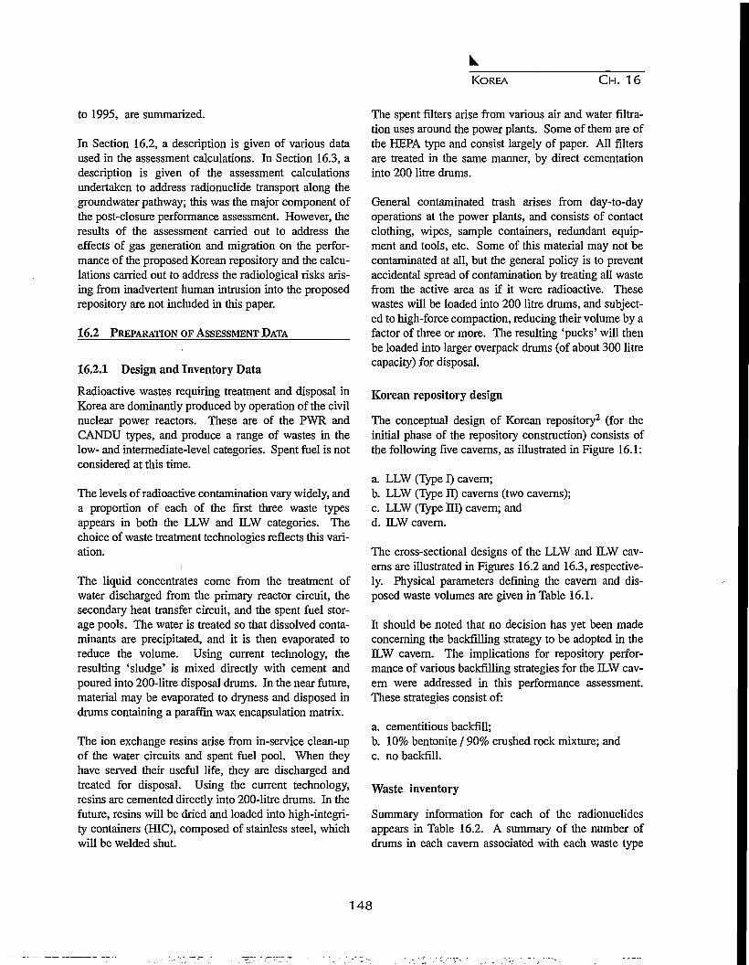
KOREA CH. 16
to 1995, are summarized.
In Section 16.2, a description is given of various dataused in the assessment calculations. In Section 16.3, adescription is given of the assessment calculationsundertaken to address radionuclide transport along thegroundwater pathway; this was the major component ofthe post-closure performance assessment. However, theresults of the assessment carried out to address theeffects of gas generation and migration on the perfor-mance of the proposed Korean repository and the calcu-lations carried out to address the radiological risks aris-ing from inadvertent human intrusion into the proposedrepository are not included in this paper.
16.2 PREPARATION OF ASSESSMENT DATA
16.2.1 Design and Inventory Data
Radioactive wastes requiring treatment and disposal inKorea are dominantly produced by operation of the civilnuclear power reactors. These are of the PWR andCANDU types, and produce a range of wastes in thelow- and intermediate-level categories. Spent fuel is notconsidered at this time.
The levels of radioactive contamination vary widely, anda proportion of each of the first three waste typesappears in both the LLW and ILW categories. Thechoice of waste treatment technologies reflects this vari-ation.
l
The liquid concentrates come from the treatment ofwater discharged from the primary reactor circuit, thesecondary heat transfer circuit, and the spent fuel stor-age pools. The water is treated so that dissolved conta-minants are precipitated, and it is then evaporated toreduce the volume. Using current technology, theresulting 'sludge' is mixed directly with cement andpoured into 200-litre disposal drums. In the near future,material may be evaporated to dryness and disposed indrums containing a paraffin wax encapsulation matrix.
The ion exchange resins arise from in-service clean-upof the water circuits and spent fuel pool. When theyhave served their useful life, they are discharged andtreated for disposal. Using the current technology,resins are cemented directly into 200-litre drums. In thefuture, resins will be dried and loaded into high-integri-ty containers (HIC), composed of stainless steel, whichwill be welded shut.
The spent filters arise from various air and water filtra-tion uses around the power plants. Some of them are ofthe HEPA type and consist largely of paper. All filtersare treated in the same manner, by direct cementationinto 200 litre drums.
General contaminated trash arises from day-to-dayoperations at the power plants, and consists of contactclothing, wipes, sample containers, redundant equip-ment and tools, etc. Some of this material may not becontaminated at all, but the general policy is to preventaccidental spread of contamination by treating all wastefrom the active area as if it were radioactive. Thesewastes will be loaded into 200 litre drums, and subject-ed to high-force compaction, reducing their volume by afactor of three or more. The resulting 'pucks' will thenbe loaded into larger overpack drums (of about 300 litrecapacity) for disposal.
Korean repository design
The conceptual design of Korean repository2 (for theinitial phase of the repository construction) consists ofthe following five caverns, as illustrated in Figure 16.1:
a. LLW (Type I) cavern;b. LLW (Type II) caverns (two caverns);c. LLW (Type HI) cavern; andd. DLW cavern.
The cross-sectional designs of the LLW and ILW cav-erns are illustrated in Figures 16.2 and 16.3, respective-ly. Physical parameters defining the cavern and dis-posed waste volumes are given in Table 16.1.
It should be noted that no decision has yet been madeconcerning the backfilling strategy to be adopted in theILW cavern. The implications for repository perfor-mance of various backfilling strategies for the ILW cav-ern were addressed in this performance assessment.These strategies consist of:
a. cementitious backfill;b. 10% bentonite / 90% crushed rock mixture; andc. no backfill.
Waste inventory
Summary information for each of the radionuclidesappears in Table 16.2. A summary of the number ofdrums in each cavern associated with each waste type
148

KOREA CH. 16
A: Ventilation Building (Exhausted)B: Ventilation Building (Supply)C: Operation BuildingD: Power Supply AreaE: Drainage Water Pumping AreaF: Maintenance Area
Figure 16.1. Proposed layout of Korean repository (Initial Phase).
Shotcrete
SteelGirder
ConcreteWal l -—.
s
-\ LLW Waste Module \—
s ^—-
u-
1
Maintenance Space
Drainage^Ditch ^Concrete
Pavement
Figure 16.2. Cross section of LLW cavern.
Shotcrete
ConcreteCompartment
DrainageDitch'
MaintenanceSpace
Concretepavement
Figure 16.3. Cross section of ELW cavern.
149

KOREA CH. 16
Table 16.1. Cavern and disposed waste volumes (m3).
Parameter LLW (Type I) LLW (Type II) (total) LLW (Type HI) ILW
Vwst(a)
vb/f(c)vexc<d>
3.85 103
1.08 104
_2.73 104
7.26 103
2.15 104
_6.06 104
3.37 103
1.08 104
_3.03 104
5.52 103
1.49 104
3.05 104
5.62 104
Notes:
(a) Volume of packaged waste in 200 litre containers.
(b) Volume of disposal module (6-pack LLW) or 8-pack (ILW).
(c) Volume of backfill (ILW only).
(d) Total volume of caverns.
and of the total volume occupied by the wasteform isprovided in Table 16.3.
16.2.2 Chemical Data
Calculations have been carried out to investigate thechemistry of the JWS-2 groundwater, collected at adepth of 330 m, which was considered to have a chem-istry most analogous to that in the vicinity of the studyarea. The aqueous speciation of this groundwater andthe likelihood of certain minerals precipitating or dis-solving has been modelled using the HARPHRQ pro-gram3 with the HATCHES database4. Further calcula-tions have been performed to predict the effect ofgroundwater equilibration with a high-calcium cement.These calculations have been used as the basis for deter-mining the solubility of a number of key radionuclidesin two groundwaters, the JWS-2 water at pH 5.7 and acement-equilibrated water at pH 12.9.
The PDFs for elemental solubility limits that were usedin this assessment were centred on the results of theHARPHRQ speciation calculations, with log-triangularPDFs covering whole orders of magnitude. The mainmaterials of interest to the conceptual repository are thein-drum cement, concrete and bentonite (candidate
Table 16.2. Radionuclide Inventory.
RadionuclideHalf-life(years)
Inventory(Bq)
3H14C60Co59N i
63N i
90Sr94Nb"Tc129J137Cs235TJ
238JJ
238pu
239pu
1.24 101
5.73 103
5.27 10°7.50 104
9.60 101
2.91 101
2.03 104
2.13 105
1.57 107
3.00 101
7.04 108
4.47 109
8.77 101
2.41 104
4.31 1012
4.11 1012
6.16 1014
1.02 1013
3.12 1014
7.95 1012
2.46 1011
3.34 1011
1.93 1010
3.41 1014
1.11 107
3.91 108
1.59 1011
3.28 10u
backfill materials for the ILW caverns), and the mineralandesite, which is the host rock considered for thisstudy.
A literature survey has been carried out to determine thelikely Rd values for sorption of radionuclides onto the
Table 16.3. Waste inventory.
Waste type
Liquid cone, in cementLiquid cone, in paraffinIon exchange resin in cementIon exchange resin in HICSpent filters in cementGeneral trash
Numberof drums
10,425-
4,516-
4,307-
LLW (Type I)
----
36,288
Volume occupiedLLW (Type II)
4,996----
11,868
(m3)LLW (Type HI)
-10,273
-
16,445882
-
ILW
3.08 103
2.05 103
9.03 102
3.29103
1.04103
9.63 103
150

KOREA C H . 16
bentonite backfill and onto the host rock formation.
16.2.3 Hydrogeological Data
The first step in the development of a numerical modelof the groundwater flow in the region around the studyarea is to develop a conceptual model of the geologicaland hydrogeological structure of the region. The gener-al direction of groundwater flow in the region aroundthe hypothetical repository location would be from thehigh ground inland towards, and roughly perpendicularto the coast. The most appropriate type of model to con-struct for this illustrative assessment was therefore atwo-dimensional vertical cross-section model along aline roughly perpendicular to the coast. It was notedthat the model would have to extend some distance off-shore so that the saline transition zone near the coastcould be modelled satisfactorily. The geological struc-ture along the main line of section selected for thegroundwater flow model is shown in Figure 16.4.
In order to carry out this preliminary assessment, inputPDFs were required for all of the hydrogeological prop-erties used in the groundwater flow and transport mod-els. The materials identified in the geological structurewere:
1. upper andesite;2. lower andesite;3. fractured lower andesite;4. granite;5. shale;6. sandstone/mudstone/siltstone sediments; and7. gneiss.
Li addition, the hydrogeological properties of the repos-itory itself, and of the access tunnels, had to be consid-ered. A PDF was required for the permeability andporosity of the material in three cases: normal rock,rock within a fault core, and rock within a fault halo.The notation T(a,b,c) is used to indicate a triangularPDF with upper and lower limits c and a, respectively,and peak value b. For convenience, logarithms to base10 were used. The hydraulic conductivity for some ofthe rock types are summarized in Table 16.4, as anexample.
16.2.4 Biosphere Data
The approach adopted is to identify critical groups, andhence to evaluate potential maximum individual risks.This evaluation is based on the definition of hypotheti-cal subsistence communities, which are assumed tomake maximum reasonable use of local food resourcesand to be located in the area of the environment assessedto be the most contaminated as a result of possible futuredischarges from the repository.
In this assessment, the screening process was carried outusing the generic biosphere program BIOS_3A5, whichconsiders a relatively wide range of potentially impor-tant pathways. On the basis of the screening calcula-tions, a simple process model was developed takingadvantage of the Compartment Biosphere submodelavailable within the MASCOT program6.
The terrestrial biosphere considered comprises thecatchment of a small river discharging into a coastal sea.The section of river that may be contaminated by
Figure 16.4. Geological structure along the line of the model cross section. Distances and elevations in metres.
151

KOREA CH. 16
Table 16.4. Summary of log-hydraulic conductivity distributions.
Rock type
AndesiteFractured AndessiteGraniteGneissShaleSandstones
Log-hvdraulic conductivity(a)
Lower bound
-12: -11
-11-13-12-10
Peak
-8-7-8-10-9
-7.6
Upper bound
-6-5-6-7-7-5
Note: (a) Values given are for log-hydraulic conductivity (permeabilities in m s"1, log to base 10).
Comment
IsotropicIsotropicIsotropicIsotropicIsotropicIsotropic
groundwater from the repository, either directly or indi-rectly (through drainage from adjacent farmland), isestimated to be 5 km in length, and the area of its asso-ciated catchment, 10 km2.
The critical group at risk from radionuclides enteringthe biosphere is assumed to be a community of subsis-tence farmers who live and work in the land. For thepreliminary assessment, their diet was assumed to besimilar to the Korean average.
The endpoint of the calculations corresponds to themaximum dose received resulting from a steady 1 Bqyr"1 release rate from the geosphere, which occurs asconcentrations in the environment approach, steady-state equilibrium values. The calculations demonstratedthat a wide range of terrestrial pathways should be con-sidered. Marine pathways, however, were found to beless important, because of much higher levels of dilutionin coastal waters. The results of the analysis usingBIOS_3A provided a basis for selecting pathways forthe second phase of the assessment using MASCOT'Sbiosphere compartment submodel facility. Terrestrialpathways considered in the second stage of the assess-
ment using MASCOT included ingestion of rice andvegetables, drinking water, consumption of meat prod-ucts (beef, milk, liver, and poultry), external gammaexposure from soil, and dust inhalation. Although lessimportant, ingestion of marine foodstuffs was also con-sidered.
Figure 16.5 shows the structure of the biosphere modeldeveloped for the preliminary assessment.
16.3 GROUNDWATER PATHWAY
16.3.1 Groundwater Flow Modelling
After the closure and resaturation of a repository forradioactive waste, it can be anticipated that radionu-clides will dissolve in groundwater flowing through thewasteform and will be transported with the groundwaterthrough the geosphere to the biosphere. This is the nat-ural pathway by which radionuclides, disposed in arepository, may return to the human environment. It isalmost certain that radionuclides will return to the bios-phere by this route, and so an analysis of the risk arisingfrom the groundwater pathway forms an important part
Figure 16.5. Structure of biosphere model.
152

KOREA CH. 16
Figure 16.6. Shade plot of the NAMMU patch grid showing assignment of rock types. The lines from the reposito-ry locations represent the access tunnels.
of an assessment of the performance of a repository forradioactive waste.
In order to carry out this analysis, it is necessary to beable to estimate the rate of groundwater flow in thevicinity of the repository (which largely determines theflux of radionuclides leaving the repository) and thenature of the regional groundwater flow system (whichdetermines the subsequent transport through thegeosphere and return to the biosphere).
The first stage in the development of a NAMMUgroundwater flow model7 of the site is the constructionof a finite-element mesh that represents the importantfeatures of the geology and topography of the site (seeFig. 16.4) and extends to regions where well-definedboundary conditions can be identified. Careful designof the finite-element mesh is necessary both to ensurethat the numerical solution is as accurate as possible andto allow for subsequent changes to the model to be madewith ease.
The top surface of the mesh was a smoothed representa-tion of the topography, treated as a number of straight-line segments that preserved the major features. Theleft-hand boundary of the model was taken to be anassumed (vertical) groundwater divide under the highground inland.
The gneiss has a very low permeability and so, in prin-ciple, the base of the sediments could have been taken toform the base of the model. However, a satisfactorytreatment of the region of saline groundwater offshorewould require that the distribution of salt concentrationon the base of the sediments be known a priori, which isnot the case. It was therefore preferable that the modelextended far enough offshore to include the offshore
surface outcrop of the gneiss. It is then reasonable toassign a constant salt concentration along the right-handboundary of the model. Figure 16.6 shows the assign-ment of rock types in the base-case model. The aim wasto produce a grid in which the largest elements wereabout 200-250 m across. In practice most of the ele-ments are considerably smaller. The final grid used forthe calculations is shown in Figure 16.7.
The overall (large-scale) flow is driven by the highheads produced by the high ground on the left-hand sideof the model and moves downwards towards the right-hand side of the model. This flow continues at depthuntil it reaches the salt front, which is intruding from theright-hand side of the model. The saline transition zoneis at the point where the driving head from the topogra-phy exactly balances the head due to the increased den-sity of the seawater. The freshwater therefore flows upthe salt front and discharges near the coast. Seawaterintrudes from the right-hand boundary of the model andflows into the model until it reaches the saline transitionzone, which it flows up before discharging through thesea bed. In the near-surface part of the model onshore,small flow cells driven by local topographic variationsare superimposed on the large-scale flow. Local dis-charge occurs in all of the small valleys represented inthe model. There is very little flow in the gneiss layer.
A series of pathline calculations were performed toinvestigate the general nature of the flow system. Thepathlines that were used for the MASCOT analysis werestarted from the following two sets of points: (3600,55),(3700,55), and (3800,55) to represent paths startingfrom the 'upper repository' (i.e. a repository located 50m above OD, about 250 m below the ground surface),and (3600, - 50), (3700, - 50), (3800, - 50) to representpathlines starting from the 'lower repository' (i.e. a
153

KOREA CH. 16
Figure 16.7. Plot of finite-element mesh.
repository located 50 m below OD, about 350 m belowthe ground surface). The travel times and path lengthsfor these paths, and the specific discharges at the repos-itory locations, are summarized in Table 16.5.
One of the pathlines that was started from the upperrepository position crossed the fault zone near the repos-itory and emerged near the tunnel entrance after a traveltime of approximately 1200 years. The other two path-lines from the upper repository position emerged up thefault zone with travel times of approximately 500 yearsafter being caught in the flow cell that discharges in thesmall valley near the fault (Fig. 16.8a). All three path-lines that started from the lower repository crossed thefault and emerged near the tunnel entrance with traveltimes of about 1100 years (Fig. 16.8b). Three pathlineswere also started from a location near the coast, solelyin order to illustrate the general nature of the flow in thevicinity of a hypothetical repository sited there. Two ofthe pathlines emerged a short distance offshore, but the
third was caught in a local flow cell and emerged in thevalley closest to the coast (see Fig.16.8c).
Finally, a calculation was performed to estimate theresaturation time of the repository. The base-case modelwas modified to apply a boundary condition of atmos-pheric pressure at the repository location. The total flowof groundwater into the repository induced by this con-dition was then estimated by integrating the specific dis-charge along the four sides of a box closely matchingthe repository location, and then multiplying the resultby the width of the repository perpendicular to the crosssection. The resaturation time is then estimated bydividing the empty volume of the repository by the vol-ume of flow towards the repository.
The total flow into the repository in the two-dimension-al model was found to be 4.67 10"6 mV1 . The reposito-ry region was taken to have a length of 440 fn perpen-dicular to the section, giving a total flow into the repos-
Path
123
Path
123
Travel time(years)
1176.2565.93432.12
Travel time(years)
1243.11114.81049.1
Table 16.5.
Pathlength(m)
1828.6971.61777.98
Pathlength(m)
1882.91722.31602.4
Results of the base-case pathline calculation.
(a) Upper Repository
Repository specific discharge(x component, m s"1)
1.2265 10-9
1.3302 10"9
1.3916 10"9
(b) Lower Repository
Repository specific discharge(x component, m s'1)
1.070210"9
1.1650 10"9
1.2276 10"9
Repository specific discharge(y component, m s"1)
-8.684 10-10
-6.9320 10-10
-5.1647 10-10
Repository specific discharge(y component, m s"1)
-7.4150 lO"10
-6.0711 lO"10
-4.684510-10
154
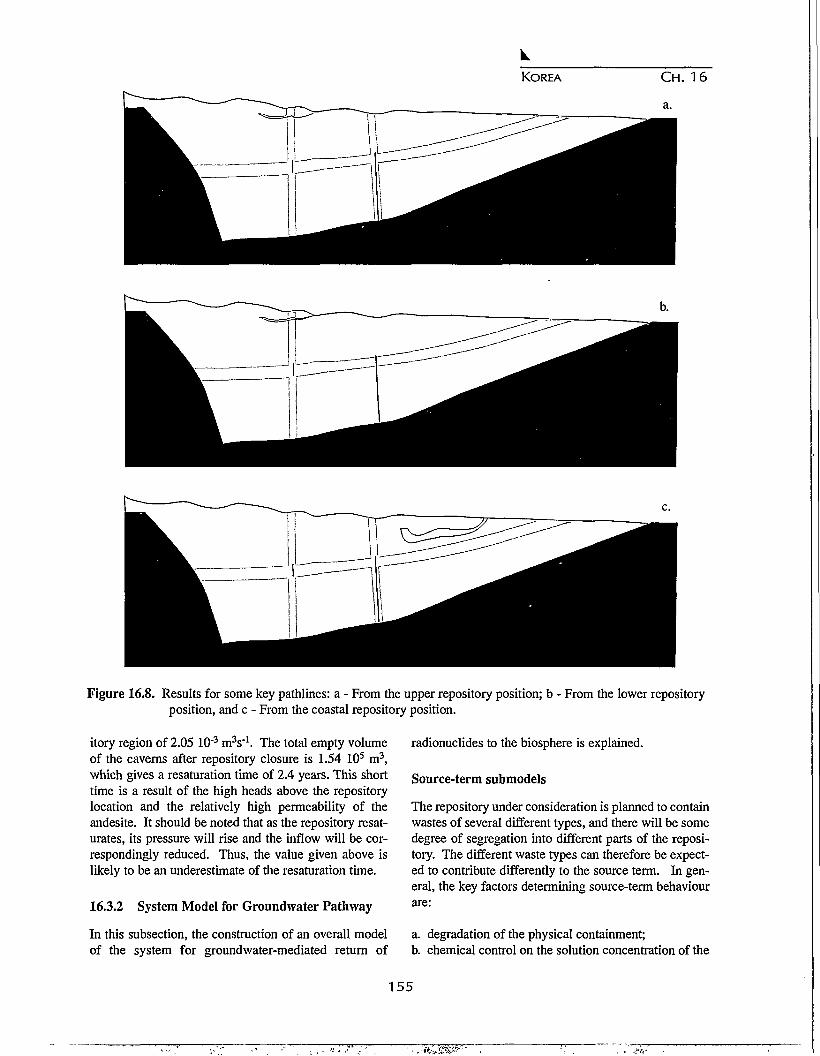
KOREA C H . 16
a.
b.
c.
Figure 16.8. Results for some key pathlines: a - From the upper repository position; b - From the lower repositoryposition, and c - From the coastal repository position.
itory region of 2.05 10'3 mV1 . The total empty volumeof the caverns after repository closure is 1.54 105 m3,which gives a resaturation time of 2.4 years. This shorttime is a result of the high heads above the repositorylocation and the relatively high permeability of theandesite. It should be noted that as the repository resat-urates, its pressure will rise and the inflow will be cor-respondingly reduced. Thus, the value given above islikely to be an underestimate of the resaturation time.
16.3.2 System Model for Groundwater Pathway
In this subsection, the construction of an overall modelof the system for groundwater-mediated return of
radionuclides to the biosphere is explained.
Source-term submodels
The repository under consideration is planned to containwastes of several different types, and there will be somedegree of segregation into different parts of the reposi-tory. The different waste types can therefore be expect-ed to contribute differently to the source term. In gen-eral, the key factors determining source-term behaviourare:
a. degradation of the physical containment;b. chemical control on the solution concentration of the
155
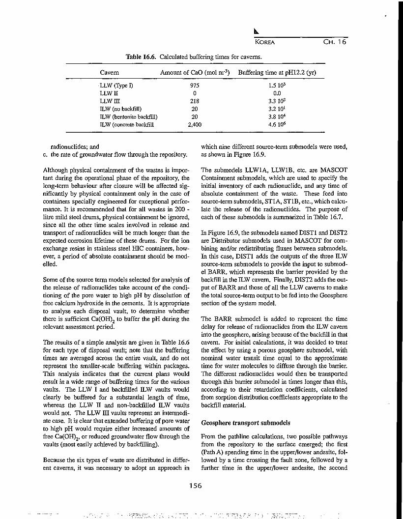
KOREA CH. 16
Table 16.6. Calculated buffering times for caverns.
Cavern Amount of CaO (mol m'3) Buffering time at pH12.2 (yr)
LLW (Type I)LLWHLLW IIIILW (no backfill)ILW (bentonite backfill)ILW (concrete backfill
9750
2182020
2,400
1.5 103
0.03.3 102
3.2 101
3.8 104
4.6 106
radionuclides; andc. the rate of groundwater flow through the repository.
Although physical containment of the wastes is impor-tant during the operational phase of the repository, thelong-term behaviour after closure will be affected sig-nificantly by physical containment only in the case ofcontainers specially engineered for exceptional perfor-mance. It is recommended that for all wastes in 200 -litre mild steel drums, physical containment be ignored,since all the other time scales involved in release andtransport of radionuclides will be much longer than theexpected corrosion lifetime of these drums. For the ionexchange resins in stainless steel HIC containers, how-ever, a period of absolute containment should be mod-elled.
Some of the source term models selected for analysis ofthe release of radionuclides take account of the condi-tioning of the pore water to high pH by dissolution offree calcium hydroxide in the cements. It is appropriateto analyse each disposal vault, to determine whetherthere is sufficient Ca(OH)2 to buffer the pH during therelevant assessment period.
The results of a simple analysis are given in Table 16.6for each type of disposal vault; note that the bufferingtimes are averaged across the entire vault, and do notrepresent the smaller-scale buffering within packages.This analysis indicates that the current plans wouldresult in a wide range of buffering times for the variousvaults. The LLW I and backfilled ILW vaults wouldclearly be buffered for a substantial length of time,whereas the LLW II and non-backfilled ILW vaultswould not. The LLW HI vaults represent an intermedi-ate case. It is clear that extended buffering of pore waterto high pH would require either increased amounts offree Ca(OH)2, or reduced groundwater flow through thevaults (most easily achieved by backfilling).
Because the six types of waste are distributed in differ-ent caverns, it was necessary to adopt an approach in
which nine different source-term submodels were used,as shown in Figure 16.9.
The submodels LLW1A, LLW1B, etc. are MASCOTContainment submodels, which are used to specify theinitial inventory of each radionuclide, and any time ofabsolute containment of the waste. These feed intosource-term submodels, ST1 A, ST1B, etc., which calcu-late the release of the radionuclides. The purpose ofeach of these submodels is summarized in Table 16.7.
In Figure 16.9, the submodels named DIST1 and DIST2are Distributor submodels used in MASCOT for com-bining and/or redistributing fluxes between submodels.In this case, DIST1 adds the outputs of the three ILWsource-term submodels to provide the input to submod-el BARR, which represents the barrier provided by thebackfill in the ILW cavern. Finally, DIST2 adds the out-put of BARR and those of all the LLW caverns to makethe total source-term output to be fed into the Geospheresection of the system model.
The BARR submodel is added to represent the timedelay for release of radionuclides from the ILW caverninto the geosphere, arising because of the backfill in thatcavern. For initial calculations, it was decided to treatthe effect by using a porous geosphere submodel, withnominal water transit time equal to the approximatetime for water molecules to diffuse through the barrier.The different radionuclides would then be transportedthrough tliis barrier submodel in times longer than this,according to their retardation coefficients, calculatedfrom sorption distribution coefficients appropriate to thebackfill material.
Geosphere transport submodels
From the pathline calculations, two possible pathwaysfrom the repository to the surface emerged; the first(Path A) spending time in the upper/lower andesite, fol-lowed by a time crossing the fault zone, followed by afurther time in the upper/lower andesite, the second
156
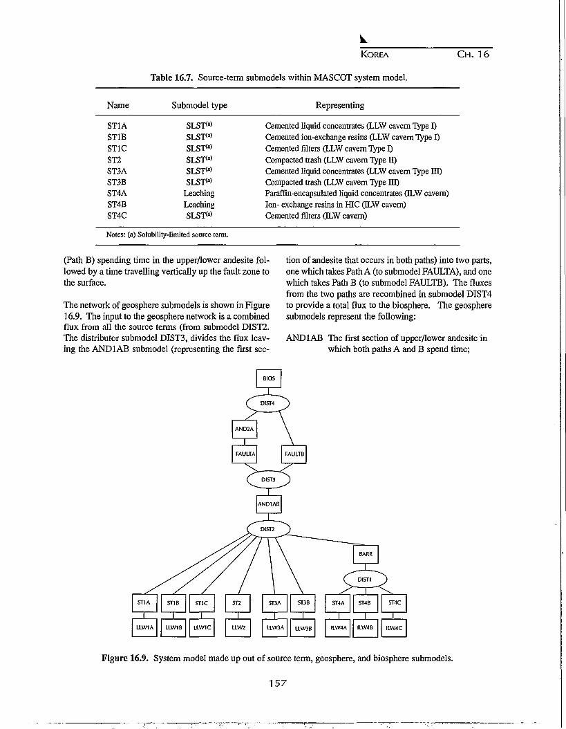
KOREA C H . 16
Table 16.7. Source-term submodels within MASCOT system model.
Representing
Cemented liquid concentrates (LLW cavern Type I)Cemented ion-exchange resins (LLW cavern Type I)Cemented filters (LLW cavern Type I)Compacted trash (LLW cavern Type II)Cemented liquid concentrates (LLW cavern Type HI)Compacted trash (LLW cavern Type IE)Paraffin-encapsulated liquid concentrates (ILW cavern)Ion- exchange resins in HIC (DLW cavern)Cemented filters (ILW cavern)
Notes: (a) Solubility-limited source term.
Name
ST1AST1BSTIC
ST2ST3AST3BST4AST4BST4C
Submodel type
SLSTM
SLST<a>
SLST<a>
SLST<a>
SLST<a>
SLST<a>
Leaching
Leaching
SLST<a>
(Path B) spending time in the upper/lower andesite fol-lowed by a time travelling vertically up the fault zone tothe surface.
The network of geosphere submodels is shown in Figure16.9. The input to the geosphere network is a combinedflux from all the source terms (from submodel DIST2.The distributor submodel DIST3, divides the flux leav-ing the AND1AB submodel (representing the first sec-
tion of andesite that occurs in both paths) into two parts,one which takes Path A (to submodel FAULTA), and onewhich takes Path B (to submodel FAULTB). The fluxesfrom the two paths are recombined in submodel DIST4to provide a total flux to the biosphere. The geospheresubmodels represent the following:
AND1AB The first section of upper/lower andesite inwhich both paths A and B spend time;
BIOS
AND2A
1FAULTA
\
FAULTB
ST1A
1LLW1A
ST1B
1LLW1B
STIC
1LLW1C
ST2
LLW2
ST3A
1LLW3A
ST3B
1LLW3B
ST4A
1ILW4A
ST4B
1ILW4B
ST4C
1ILW4C
Figure 16.9. System model made up out of source term, geosphere, and biosphere submodels.
157

KOREA CH. 16
c<
10-5 n
10"6 -|
io-7
10"8
10-9
1 o- io
1 Q -12
— — — Lower WLower RLower DSUpper WUpper RUpper DS
0° 101
<ey to Legend:
10
'Upper''Lower''DS'
2 103 104
Time (yr)
Upper repository locationLower repository locationDeep soil biosphere
'R'W
105 106
River biosphereWell biosphere
Figure 16.10. Total annual individual risk as a function of time for the upper and lower repository locations foreach biosphere.
FAULTA Path A in the fault zone;FAULTB Path B in the fault zone to the surface;AND2A Path A in the second section of upper/lower
andesite to the surface.
All these submodels are MASCOT Porous Geospheresubmodels. This type of submodel assumes that therock matrix is fully accessed and hence the porosity isthe full matrix porosity.
Biosphere submodels
Three exposure pathways were considered, in which theflux from the geosphere is released to the deep soil, ariver and a well. Three identical compartment biospheresubmodels (DEEPSOIL, RIVER and WELL) were usedin MASCOT to represent the three exposure pathways,each taking as its input the entire flux from thegeosphere. The difference between the three submodelswas that the inlet was to different compartmentsappropriate to the three exposure pathways. The com-partment structure of the biosphere is shown in Figure16.5. The outlet from the biosphere was in each case atotal dose from concentrations in soil, water (river orirrigation) and seawater.
16.3.3 Results
The total annual individual risks calculated for each
biosphere model for the upper and lower repositorylocations are shown as functions of time in Figure 16.10.It can be seen that for both locations, the deep soil andwell biospheres give very similar peak risks (marginallyhigher in the case of the well), whereas the river bios-phere gives risks which are about two orders of magni-tude lower.
The risk values, being obtained from mean doses thatare estimated from a finite number of realizations (1000for these runs), are subject to statistical error. From thevariance of the observed values, this error can be esti-mated, and typical 95% confidence intervals are shownin Figure 16.11 (for the lower repository location). Formost of the time-range, the upper 95% confidence limitexceeds the best estimate by a factor of about 1.5 or less.This is considered perfectly adequate for a preliminaryassessment, with many uncertainties in the data and inthe model choices that may well cause biases of rathergreater magnitude. The statistical estimation errorscould be reduced by including more realizations; tohalve the error, four times the number of realizationswould be necessary.
16.3.4 Discussion
Risk levels
Using the models and data adopted for these assessment
158

KOREA CH. 16
10"5 -,
10"6 -I
10-7 H
2 1Q-8 _jm3
I io-9 AS 10"10 J
l 0i-12
10°
— Lower 95— Upper 95• - Mean
10 10 103 104
Time (yr)
105 106
Figure 16.11. Total annual individual risk for release to the deep soil biosphere for the lower repository locationplotted against time (with 95% confidence limits).
calculations, it was found, for both choices of reposito-ry location and for all the alternative assumptions aboutthe release point to the biosphere, that the predicted riskremained below the target of 10'5 yr1 throughout theperiod of detailed quantitative assessment, up to 1000years after closure. Beyond this time, no dramaticincreases in risk were found, the greatest calculatedmean risk being 1.4 10"6 between 104 and 105 yearspost-closure.
Because of the parameter-value uncertainties, which theprobabilistic approach is designed to treat, differentsampled realizations of the system gave conditionalrisks either higher or lower than the mean. From thecalculated distributions, it was found that there was aprobability of 0.25 to 0.30 of exceeding a risk of 10-6fortimes up to 103 years, and a probability of about 0.50 ofexceeding a risk of 10'6 for times up to 106 years.
Important radionuclides
Up to 1000 years after closure, only 129I makes a signif-icant contribution to risk, other radionuclides eitherbeing effectively contained, or else delayed in their pas-sage through the geosphere. Beyond the 1000-yearperiod, the only significant additional contributor to riskwas found to be 59Ni.
Effects of the alternative biosphere models
The risk curve for 129I when using the biosphere modelin which discharge to the deep soil is assumed, shows a
substantially greater initial delay relative to that foundusing the river or well biosphere models. This suggeststhat the transport process (when present) from the deepsoil to the other compartments provides a non-negligiblesupplement to the geosphere travel times. Apart fromthis difference, the shapes of the risk versus time curvesfor the three biosphere models are very similar.
Differences between the upper and lower repositorylocations
The peak risk for the upper repository location wasfound to be 9.8 10"7 for the deep soil biosphere and isdue to 59Ni. The 59Ni curve clearly shows the differencebetween paths A and B as two separate peaks. For thelower repository location, the peak risk is higher, at 1.410'6for the deep soil biosphere. In fact, the travel timesare in general longer from the lower repository location.However, in this case the two peaks arising from pathsA and B are not so obviously separated. For the lowerrepository location, the travel times for the total Path Aand the total Path B are more comparable than they arefor the upper repository location, and the reason that therisk is lower in the case of the upper location is that thelarger difference between paths A and B causes morespreading to occur in the geosphere and hence reducesthe risk. This interesting result shows that the spreadingof arrival of radionuclides at the surface is not just amatter of hydrodynamic dispersion, but can be con-tributed to by division of the transport between majoralternative paths. However, it should be noted that thesetwo calculations provide insufficient evidence to draw
159

KOREA C H . 16
general conclusions about the relationship betweenrepository placement and the extent of this type of dis-persion.
Effect of parameter uncertainties
Whereas the expected contribution to risk from 59Niarises from just a small number of realizations that leadto relatively high conditional risks (those in which boththe geosphere travel time and retardation of Ni are low),the contribution to risk from 129I arises from a moderaterisk in almost all realizations. This shows that thepotential contribution to risk from 59Ni could be subjectto significant revision as future reductions are achievedin the present uncertainty about hydrogeological condi-tions and the retardation of Ni in the geosphere.
16.4 SUMMARY OF PROBABILISTIC SAFETY
ASSESSMENT
A number of deterministic variant calculations were car-ried out, to explore the sensitivity of the system perfor-mance to several hypothetical changes. The changesaddressed were:
a. no backfill in the ILW caverns;b. concrete backfill in the ILW caverns;c. high specific discharge at the source;d. reduced geosphere travel times;e. combination of (c) and (d); andf. low near-field sorption coefficients.
These variations were considered relative to a base casedefined by giving to each uncertain parameter in theprobabilistic calculations its best-estimate value (themode or median of the PDF).
The main conclusions are summarized here.
a. The overall peak total risk is similar in the determin-istic base case to that given by the probabilistic cal-culations.
b. In the time range 102 to 104 years, 129I is the domi-nant contributor to risk, as in the probabilistic calcu-lations.
c. 59Ni hardly contributes at all to risk in the determin-istic base case, indicating that its significant contri-bution to the mean risks arises from realizations withless than average return time of this radionuclide tothe biosphere.
d. Removal of the barrier provided by the ILW backfill
was found to affect risk significantly; in the case ofthe 129I contribution, this is mainly due to its effect onthe spreading in time of the release to the geosphere,whereas for 59Ni it is associated with the change intravel time affecting the amount of decay.
e. Decreasing the barrier thickness would increaserisks, to an extent intermediate between the base caseand the variant with zero thickness; increasing thebarrier thickness, however, is unlikely to reduce riskssignificantly relative to the base case.
f. Decreased groundwater travel times in the geosphereleads to a significant increase in risk; in the case ofthe 129I contribution, this is mainly due to the associ-ated reduction in the spreading in time of the arrivalin the biosphere, whereas for 59Ni, the effect isbecause reduced travel times allow less decay tooccur.
g. The variants involving either an increased flux ofgroundwater through the repository, or changes tonear-field chemistry, do not lead to very greatincreases of risk relative to the base case.
REFERENCES
1. Agg, P. J., et al., P-KAERI 94 Performance andEnvironmental Assessment of a Radioactive WasteRepository in Korea, NEMAC/AEA Technology,1995.
2. Park, H. S., et al., A Study on the Requirements forBasic Design of a Repository for Low-Level Radio-active Waste, KAERI-NEMAC/PR-32/93,1994.
3. Brown, P. L., et al., HARPHRQ: A GeochemicalSpeciation Program Based on PHREEQE, NSS/R188,UKNirex, 1991.
4. Cross, J. E., et al., HATCHES - A ThermodynamicDatabase and Management System, NSS/R212, UKNirex, 1990.
5. Martin, J. S., et al., User Guide for BIOS-3A, NRPB-M285, NRPB, 1991.
6. Sinclair, J. E., et al., MASCOT and MOP Programsfor Probabilistic Safety Assessment, NSS/R336, UKNirex, 1994.
7 Hartley, L. J., and C. P. Jackson, NAMMU (Release6.1) User's Guide, AEA-D&R-0472 (Release 6.1),AEA Technology, 1993.
160

CHAPTER 17
RESEARCH O N RADIOACTIVE WASTE DISPOSAL IN THE NETHERLANDS
WITH SPECIAL REFERENCE TO EARTH SCIENTIFIC STUDIES
A.F.B. Wildenborg
Rijks Geologische Dienst, P.O. Box 157, NL-2000 AD Haarlem, The Netherlands
17.1 INTRODUCTION
Investigations for radioactive waste disposal in theNetherlands were carried out within the framework ofthe OPLA research programme (OPLA is a Dutchacronym for 'Disposal on Land')- The programmeintended to explore the disposal options for nuclearwaste in the deep subsurface below the Netherlands.Initially, the research focused on rock salt as a host rock.
Massive bodies of rock salt, with a thickness of 200 to3,000 m, are present in the subsurface of the northernNetherlands. This potential host rock for radioactivewaste disposal was deposited in layers about 220 to 250Ma ago (the Zechstein period) by evaporation of aclosed or semi-closed marine basin. After the evaporiteswere covered by fresh sediments, the layered salt start-ed to flow at several places in the subsurface of theNetherlands. At many locations this resulted in the for-mation of salt pillows and sometimes, successively insalt diapirs. The tops of the shallowest salt diapirs roseto depths of about 100 m below the surface. The non-disturbed layered salt is situated generally at a depth ofseveral kilometres below the earth's surface.
The OPLA research programme was divided into threephases for purposes of the interim parliamentary deci-sion-taking procedure. At the end of each phase, gov-ernment and parliament decide on the question ofwhether a subsequent phase of the programme is to beperformed and, if so, what content and scope it shouldthen have.
Execution of the first phase commenced in 1984. Thisfirst phase comprised a feasibility study, investigatingvarious disposal methods and salt formation types withreference to safety. For that purpose, desk studies and
laboratory investigations were performed on the basis ofexisting data in the public domain. In many cases, theseinvestigations were carried out in international co-oper-ation, for example in the area of in situ investigations.No decisions have been taken as yet regarding the exe-cution of any further phases of the research programme,which will be more site-specific.
The OPLA Committee reported on the first phase of theresearch programme in mid 1989. A review of the firstphase was given by Van Montfrans in the precedingissue (1991) of the present world-wide review. The con-clusions of the studies undertaken in that programmeamount, in brief, to a statement that safe disposal ofradioactive waste in rock salt formations of a nature andscale as very probably occur in the Dutch subsurface is,in principle, feasible. The OPLA Committee also con-cluded that certain assumptions on which the conclu-sions were based required further verification to estab-lish their reliability and accuracy. It was furthermorefound that the possibility of identifying in concreteterms exactly which salt formations would be most eli-gible for further investigation on technical grounds waslimited by a lack of site-specific data.
At the same time, according to the ILONA Committee(advising on the policy for radioactive waste manage-ment in the Netherlands) it was possible and necessaryto perform supplementary research in order to reducethe limitations and margins of uncertainty established ina number of respects by the 1989 findings. This viewwas supported by the results of an international reviewperformed by the European Community (EC) and theNuclear Energy Agency (NEA) of the Organisation forEconomic Co-operation and Development (OECD). Inaddition, it was considered important that attentionshould be given to new developments, such as the
161

NETHERLANDS CH. 17
retrievability of disposed-of waste.
17.2 CONTENT AND STRUCTURE OF THE
SUPPLEMENTARY RESEARCH PROGRAMME
Based on the conclusions and recommendations of thefirst phase and the results of the EC/NEA review, theOPLA Committee formulated the main themes of a lim-ited programme of supplementary research, "Phase 1A"(OPLA Committee, 1993). The most important themesare:
• Analysis and reduction of bandwidths in the results ofPhase 1, particularly in the results of the safety analy-sis. This task invoked an improvement of the method-ology of the Phase 1 safety approach. This approachwas expanded into a methodology enabling systemat-ic treatment of disposal risks. This improves the inter-comparability of risks, and makes it possible to allowfor probabilities of processes and data.
• In addition, careful analysis and further enlargementof the database on the subsurface was required. At thesame time, the extension and further validation of thegeneric computer models applied in Phase 1 weredealt with. New models, describing the long-termgeological evolution of the subsurface, were devel-oped as well. The approach outlined above provides abetter confirmatory basis for the findings of the safe-ty study, and they may therefore be considered moreaccurate.
• Classification of salt formations for further investiga-tion. Grouping of the salt formations was carried outon the basis of expected long-term stability andaccommodation space for repository designs. Thistheme will not be discussed further in the presentreport.
At the same time, the Committee was requested to con-sider new developments; these are classed as a separatemain theme. Two topics were dealt with in this theme,viz. the retrievability of disposed-of radioactive wasteand the direct disposal of spent fuel elements.Further, the Committee strongly advocated participationin international research programmes.
The supplementary programme was performed in theperiod from mid 1990 to mid 1993. Within the pro-gramme about 20 studies were performed in the areas ofstudy of the OPLA research programme. These areas ofstudy had already been considered in Phase 1: safety (thecentral theme), technical feasibility (mining engineer-ing), geology and geohydrology, rock mechanics and
radiation effects. This paper will deal with results of thesupplementary programme and in particular will focuson the outcome of the various earth scientific back-ground studies.
17.3 SAFETY ANALYSIS
Progress was made on the following matters:
• risk assessment method; and• data and models needed for the risk assessment.
17.3.1 Health risk assessment method
In Phase 1, the health risks of disposal were calculatedon a deterministic and conservative basis, i.e. choosingcircumstances unfavourable for safety and thereby over-estimating risks. This approach hampered the inter-com-parability of risks for the various disposal concepts inPhase 1. In addition, this method did not allow uncer-tainties and sensitivities to be treated in an adequate way.
Within the supplementary programme, a method wasdeveloped known as PROSA (PRobabilistischOnderzoek aan de veiligheid van in Steenzout opgebor-gen radioactief Afval = Probabilistic study into the safe-ty of radioactive waste disposed of in rock salt), whichaccounts systematically for the probability of processesand subsurface data (Prij et al., 1993a). As a result, therisks as calculated are better confirmed and are morereadily inter-comparable. The systematic treatment ofuncertainties was incorporated within PROSA, therebyimproving the significance of the sensitivity analysis ascompared to Phase 1.
The PROSA method is essentially based on a systemdeveloped for the determination and selection of scenar-ios (possible situations in which radionuclides arereleased from a repository and can potentially reach thebiosphere). The method is based on the internationallyaccepted multi-barrier system, which comprises threebarriers:
• engineered barriers of the repository;• rock salt around the repository; and• overburden with aquifers and impermeable strata.
The degree in which this system acts as a barrier isaffected by a complex of Features, Events and Processes(FEPs). These FEPs were used to construct scenarios rel-evant to conditions in the Netherlands. These scenarioscan be subdivided into three classes:
162

NETHERLANDS C H . 17
Surface Erosion
T2 Biosphere T,
Figure 17.1. Schematic representation of the dissolu-tion/diapirism scenario (Prij et al., 1993a).
• Subrosion/diapirism scenarios belonging to the cate-gory of normal evolution scenarios (Fig. 17.1).Gradual ascent of a salt dome (diapirism) brings itinto contact with groundwater, salt dissolves (subro-sion), radionuclides from the repository enter thegroundwater and from there travel into the biosphere.
• Flooding scenarios belonging to the category ofaltered evolution scenarios. Groundwater penetratesinto the repository, for example, as a result of frac-turing or a water-permeable inclusion in the rocksalt. Radionuclides and salt dissolve in this water.Convergence of the disposal chambers in the saltnext forces the brine contaminated with radionu-clides out of the salt into the groundwater. Theradionuclides then enter the biosphere via thegroundwater.
• Human intrusion scenarios belonging to the categoryof disruptive event scenarios. Various forms of min-ing engineering activities (exploratory drilling, con-struction of a mine) may bring future generationsinto involuntary contact with the waste (see also Prij,1993).
Due to the lack of sufficient knowledge, two phenome-na considered potentially important could not yet befully calculated with the PROSA method: glaciation(the consequences of an ice age for the repository) andgas formation (consequences for the repository of gasformation near the waste resulting from thermal andradiation effects). Further, only those human intrusionscenarios were recalculated where improved insight rel-ative to Phase 1 made it meaningful to do so.
In the supplementary programme, the risks were calcu-lated for each of the above-mentioned scenario classes
and for a number of schematised disposal situations inDutch rock salt. The assumptions applied are based onthe currently available data on the nature and size ofrock salt formations as these very probably occur in theDutch subsurface.
17.3.2 Data and Models Needed for RiskCalculations
Calculating the risk of subsurface disposal requiresamong other things a comprehensive database relatingto the structure and the groundwater system of the sub-surface. This database yields the necessary descriptionof the multi-barrier system. For the purpose of the riskcalculations, the processes involved in transportingradionuclides through this multi-barrier system aredescribed by means of models.
The database built up in Phase 1 with published data onthe subsurface was found to be limited in scale and use-fulness. The supplementary desk studies thereforeincorporated thorough analysis and enlargement of thatgeological and geohydrological database. This led to thedetermination of a number of bandwidths, for example,for spatial geological data on salt formations. In otherrespects, too, the precision of the data has beenimproved, for example, on the size of salt formations,rate of diapirism (Fig. 17.2, lower than had to beassumed in 1989), speed of dissolution processes ofrock salt in ground water (Fig. 17.3, subrosion), struc-ture and permeability of the rock surrounding the salt,and the mechanical behaviour of salt under the action oftemperature effects. In addition, the database was sup-
1.00
0.90
0.80
0.70
0.60
0.50
0.40
030
0.20
0.10
0.00
- ,
' I
-
, 1
w
\"i *\
i"i *\
f - L x ' • - " / , ' _"* L
0.202 0302 0.402
internal rise rate [mm/a]
Figure 17.2. Probability density of the average internalrise rate for salt domes in the Netherlandsand Germany (Prij et al., 1993a).
163

NETHERLANDS CH. 17
1
2.8-2.6-2.4-2.2-
2-1.8-1.6-1.4-1.2-
10.8-0.6-0.4-0.2-
055 105 155 205 255 305
Depth (m)355 405 455 505 555
• measured fitted n=0.20 — - n=1.00
Figure 17.3. Input parameter of the depth-dependentsubrosion rate. The measured values havebeen calculated for salt domes in Ger-many and the Netherlands with predomi-nantly Quaternary subrosion activity. Theupper line corresponds to a power-fit withexponent -0.2 and for the lower line thisvalue is -1.0. The middle line with expo-nent = 0.64 has been used in the calcula-tions (Prij et al., 1993a).
plemented with data on the subsurface which havebecome available by the geological mapping of theNetherlands and from geological exploration of theNorth Sea. This material also made a contributiontowards improving the precision of the data.
In Phase 1, three important models were developed andapplied for making risk calculations:
• release and transport model for radionuclides fromthe rock salt;
• transport model for radionuclides in the subsurface;and
• transport and exposure model for the biosphere.
These models underwent limited practical validation inPhase 1. Supplementary research proved the possibilityof developing these - essentially generic - models fur-ther and validating them against a number of actualpractical situations and data. For instance, the modeldescribing the transport of radionuclides in rock salt wasfurther confirmed with results from in situ experiments(the Asse Mine in Germany), i.e. under the action ofsuch temperature and pressure as occur in an actual dis-posal situation. These results indicate that during the ini-
tial period of disposal, subsurface spaces in rock salt areclosing by convergence more rapidly than was previous-ly assumed. Further validation of this convergenceprocess with reference to more practical data is neededin view of its great impact on safety.
In recent years, the model for radionuclides transportthrough the subsurface, named METROPOL, has suc-cessfully undergone comprehensive international vali-dation in the INTRAVAL project (INternationalTRAnsport model VALidation; Leijnse &Hassanizadeh, 1994; Van de Weerd et al., 1994; VanWeert et al., 1994; Leijnse et al., 1996 submitted).Comparison with other models within this project con-firmed the reliability of this model. Its applicability toan actual situation was also demonstrated. For condi-tions prevailing in the Netherlands, this is supported bya case study on the Zuidwending salt dome (Oostrom etal., 1993).
The above-mentioned studies on processes and modelsand in particular the practical validation of these modelshave yielded greater clarity on the question of whichdata are needed for an adequate description of process-es such as convergence, diapirism, subrosion and ero-sion.
17.3.3 Risks of Considered Scenarios
As stated above, by comparison with the approach inPhase 1 the present safety approach has yielded animproved insight into the uncertainties associated withthe risks of geological disposal. The risks as now calcu-lated are therefore to be regarded as more precise.Using the PROSA method to calculate the risks of thesubrosion/diapirism scenarios yields values smaller than10"9/year. Similar risk values were found in Phase 1.
For the flooding scenarios, improved insights as com-pared to Phase 1 allowed modification of the rate of theprocess whereby subsurface spaces in rock salt are clos-ing (convergence). The resultant radiation doses follow-ing dispersal of the radionuclides in the biosphere arefound to be very low, and the associated risks muchlower than as calculated in Phase 1, namely smaller than10-10/year.
The above-mentioned model modification for the con-vergence process in rock salt also has an importantinfluence on the human intrusion scenario further con-sidered (a leaking storage cavern near the repository).The risks now calculated are significantly lower than
164

NETHERLANDS C H . 17
Phase 1. For the human intrusion scenarios not analysedin PROSA, the risk appearing from the Phase 1 figuresis smaller than 10"6/year. Because large variations canoccur in the transport of nuclides in the salt formation,in the overburden and in the biosphere, there is a largespread in the resulting risks calculated. Nevertheless,for all the scenarios considered the disposal riskremains smaller than 10'6/year, and for "natural" sce-narios (subrosion, diapirism, flooding) even smallerthan 10-9/year.
17.3.4 Risk Determining Features
Certain features of a repository and the geological bar-rier system around it may be determining for the risk ofthis particular facility. These features can be identifiedby determining the influence of all possible FEPs on therisk (sensitivity analysis). Phase 1 showed that theapproach then used did not possess sufficient discrimi-nating power to identify risk-determining features of arepository and the multi-barrier system. The principaldrawback lay in the conservative approach and theuncertainty as to the extent thereof for each of the dis-posal situations considered.
Development of the PROSA method made it possible toeliminate this drawback by allowing a systematicapproach and introducing the probability aspect. Thismakes it meaningful to perform a sensitivity analysis toidentify risk-determining features of the multi-barriersystem. From this sensitivity analysis, it follows that onthe basis of the currently available limited databasethere are two features which predominantly determinethe risk of the "natural" scenarios, namely:
• depth of the repository; and• rate at which this facility is uplifted by possible
diapirism.
To summarise, it may be stated that application of thecurrently available version of the PROSA method to anumber of important scenarios and disposal conceptshas proved extremely useful. In the first place, this sys-tem, as indicated above, provides an improved insightinto the risks and uncertainties. Secondly, it helps, forexample by means of the risk-determining features, toguide the direction of research in the various sub-areasof the OPLA programme.
17.4 TECHNICAL FEASIBILITY
In Phase 1, two different disposal techniques were stud-
ied:• conventional (dry) mine, and• deep boreholes drilled from the surface, in combina-
tion with caverns.
After study, it was concluded that both techniques are,in principle, technically feasible for salt formations inthe Netherlands.
For the mine concept, the supplementary research pro-gramme provided further confirmation for that conclu-sion with the following findings:
• In co-operation with Germany, the practical feasibil-ity has been demonstrated of a mine provided withdeep boreholes, dry-drilled from a gallery to a depthof several hundred metres. These boreholes, intend-ed for disposal of canisters with fission waste, con-stitute an important part of the mine concept.
• Within the same co-operative project, the practicaldevelopment of a system for lowering, transportingand emplacing radioactive waste canisters in a dis-posal mine according to the German design has beensuccessfully completed. In addition, the availabilityof a test facility for in situ investigation into rock salthas made a major contribution towards the acquisi-tion of mining engineering experience (the HAWproject in the Asse Mine; Prij & Hamilton, 1992; seealso section 17.6.1).
• Important advances have been made with regard totechnical feasibility, especially relating to the con-vergence process of rock salt (see section 17.6.1 forfurther information).
• As a result of the effects of radiation and heat, gasformation and radiation damage can occur in thevicinity of the radioactive waste disposed of in therock salt. Conclusions regarding the significance ofthe two phenomena for mine design and disposalsafety are still of a preliminary nature (see section17.6.2 for further information).
With regard to the "deep boreholes from the surfacecombined with caverns" disposal technique, Phase 1found that inspection of the reliability of the boreholeand cavern seals was an item demanding special atten-tion. In spite of supplementary literature research, noessential progress has been made in this area(Technische Universiteit Delft, 1993b). On the otherhand, it has been found that the depth range of this dis-posal technique exceeds the range found in Phase 1.Depending on the diameter, depths down to around3000 m are technically feasible with the deep borehole
165

NETHERLANDS CH. 17
technique.
17.5 EARTH SCIENTIFIC BACKGROUND STUDIES
The major tasks of earth scientific research for radwastedisposal are the description of the present state of thegeological barriers (site characterisation) and the pre-diction of the future state of the geological barriers insupport of the scenario analysis.
The supplementary research in the areas of geology andgeohydrology consists of two parts:
• improving data and models to support the risk calcu-lations in the safety study (see also section 17.3); and
• increasing the basic knowledge which is needed forproper understanding of important processes in thesubsurface. This item includes a number of subjectswhich emerged as recommendations from Phase 1,and which are not yet immediately applicable in thesafety study at this time. Results will be discussed inthis section.
17.5.1 Data Quality and Methods of DataCollection
Uncertainty Analysis of Available Geological Data
This research topic deals with the reliability of spatialgeological data in general and more specifically with thedepth values of geological horizons on contour mapsand vertical profiles which are available for the researchin the OPLA programme (Wildenborg et al., 1993). Anuncertainty analysis of geological data was not carriedout during Phase 1 of the OPLA programme.
For this analysis, the following approach was used; var-ious sources of error are responsible for the differencesin depth values between observed and real values. Thoseerror sources are introduced by the acquisition of basicdata (borehole data and seismic reflection data), by pro-cessing and interpretation and also during the construc-tion of derived spatial data like contour maps and verti-cal profiles. After analysis of the various error sourcesinvolved, the magnitudes of the error sources are quan-tified in standard deviations of the difference betweenreal and observed depth. Assuming mutual indepen-dence, all standard deviations of the sources of observa-tion errors could be summed up to obtain insight in thetotal standard deviation of the observation error :
Square RootSemi-Variance (m)
(i)
2000 4000 6000 8000 10000
Distance Between Samples (m)
Figure 17.4. Semi-variogram of depth data derivedfrom seismic observations.
where: s = standard deviation, zw= observed depth,ze= expected depth, n= number of observations
This analysis was performed on derived spatial data,namely contour maps and vertical profiles (Fig. 17.4).
Borehole data and seismic reflection data are both usedas original data for the construction of the spatial datamentioned. Borehole data are highly reliable. The stan-dard deviation of the observation error of the depths tothe base of the Tertiary and the top of the Zechstein areestimated to 2 m. Seismic reflection data are less reli-able; the standard deviations of the observation errorscould be as high as 125 m.
To construct a contour map, interpolation of the originaldata is necessary. Interpolation by itself is anothersource of error which increases with increasing distancefrom data points. The interpolation error also dependson the structural complexity (average dip) of the geo-logical horizon). Using the estimations of the standarddeviations of the observation error of borehole and seis-mic reflection data and the standard deviations of theinterpolation error, it was possible to construct mapsshowing the place-dependent standard deviation of thetop of the Zechstein around salt structures, and the baseof the Tertiary above the salt.
Methods of Data Collection
Data on the shallow subsurface are available to a rea-sonable extent when it comes to investigating and mod-elling important geological and geohydrological
166
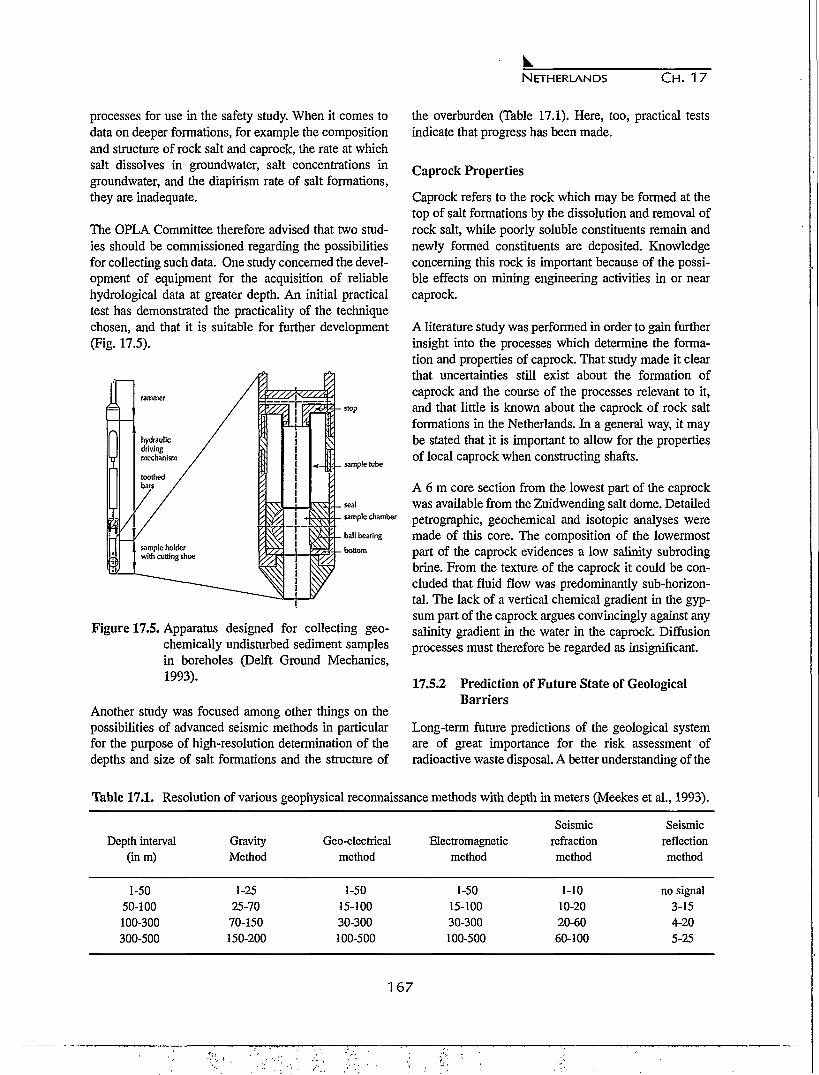
NETHERLANDS C H . 17
processes for use in the safety study. When it comes todata on deeper formations, for example the compositionand structure of rock salt and caprock, the rate at whichsalt dissolves in groundwater, salt concentrations ingroundwater, and the diapirism rate of salt formations,they are inadequate.
The OPLA Committee therefore advised that two stud-ies should be commissioned regarding the possibilitiesfor collecting such data. One study concerned the devel-opment of equipment for the acquisition of reliablehydrological data at greater depth. An initial practicaltest has demonstrated the practicality of the techniquechosen, and that it is suitable for further development(Fig. 17.5).
I
Figure 17.5. Apparatus designed for collecting geo-chemically undisturbed sediment samplesin boreholes (Delft Ground Mechanics,1993).
Another study was focused among other things on thepossibilities of advanced seismic methods in particularfor the purpose of high-resolution determination of thedepths and size of salt formations and the structure of
the overburden (Table 17.1). Here, too, practical testsindicate that progress has been made.
Caprock Properties
Caprock refers to the rock which may be formed at thetop of salt formations by the dissolution and removal ofrock salt, while poorly soluble constituents remain andnewly formed constituents are deposited. Knowledgeconcerning this rock is important because of the possi-ble effects on mining engineering activities in or nearcaprock.
A literature study was performed in order to gain furtherinsight into the processes which determine the forma-tion and properties of caprock. That study made it clearthat uncertainties still exist about the formation ofcaprock and the course of the processes relevant to it,and that little is known about the caprock of rock saltformations in the Netherlands. In a general way, it maybe stated that it is important to allow for the propertiesof local caprock when constructing shafts.
A 6 m core section from the lowest part of the caprockwas available from the Zuidwending salt dome. Detailedpetrographic, geochemical and isotopic analyses weremade of this core. The composition of the lowermostpart of the caprock evidences a low salinity subrodingbrine. From the texture of the caprock it could be con-cluded that fluid flow was predominantly sub-horizon-tal. The lack of a vertical chemical gradient in the gyp-sum part of the caprock argues convincingly against anysalinity gradient in the water in the caprock. Diffusionprocesses must therefore be regarded as insignificant.
17.5.2 Prediction of Future State of GeologicalBarriers
Long-term future predictions of the geological systemare of great importance for the risk assessment ofradioactive waste disposal. A better understanding of the
Table 17.1. Resolution of various geophysical reconnaissance methods with depth in meters (Meekes et al., 1993).
Depth interval(inm)
1-5050-100100-300300-500
GravityMethod
1-2525-70
70-150150-200
Geo-electricalmethod
1-5015-10030-300100-500
Electromagneticmethod
1-5015-10030-300100-500
Seismicrefractionmethod
1-1010-2020-6060-100
Seismicreflectionmethod
no signal3-154-205-25
167

NETHERLANDS CH. 17
physical and chemical mechanisms of the processes thataffect the geological barriers, contributes significantly toa more reliable prognosis of the future state of the sub-surface. For rock salt, three processes have been identi-fied that may directly influence the geometry of the rock.These are salt movement, salt dissolution and erosion.Modelling studies have been performed to investigatetheir relation with the major climatic and geodynamicforces, and their effect on the geological barriers(Wildenborg et al., 1993).
The possible future states of the natural barriers are ingeneral introduced as discrete scenarios in the safetystudies. A drawback of this approach is that the totaleffect of all natural release scenarios is difficult toassess. Geological processes are in varying degree cou-pled to one another, which makes it difficult or evenimpossible to split the system in several autonomouscompartments. Therefore, it is advisable to pursue anintegrated approach parallel or complementary to thescenario method, in which the whole natural barrier sys-tem, the processes inclusive, is considered as one entity.
An example of a coupled system is the relation betweenclimatic processes and surface or near-surface processes.Our knowledge of the impact on geologic disposal ofrecurrent ice ages, induced by climatic changes, has beensubstantially expanded (Wildenborg et al., 1990). Thegeological cycles concerned are relatively short, with alength of about 100,000 years, and have almost com-pletely dominated the surface or near-surface processesin Northern Europe for the past one million years. Thisknowledge, based on comprehensive observations ofdeposits formed during a number of past cycles, makesit possible to model a large part of these processes intheir relevance to the disposal issue. This holds especial-ly for the effects of salt dissolution and erosion on thesalt barrier.
Barrier Model
A geological barrier model ideally should simulate thefuture evolution of the barriers over a period of 10s to 106
years, should comprise physical and chemical formula-tions of all relevant processes that directly or indirectlyaffect the future barrier state and is driven by time-dependent climatic and tectonic forcing mechanisms.Since the beginning of the eighties, various models havebeen developed to simulate the future behaviour of thegeological system in connection with radioactive wastedisposal, e.g. GSM and FFSM in the United States,CASTOR in France and TIME4 in Great Britain.Central in the barrier model to be developed is the local
submodel describing the geometry and the properties ofthe various geological barriers around the disposal facil-ity. The locally operating processes like salt dissolution,salt movement and erosion are incorporated in this partof the model. The climatic and geodynamic boundaryconditions are generated in supraregional submodels onthe scale of NW Europe or on an even larger scale.Geological observational data have to be gathered in asystematical way to provide input data for the model anddata for extensive testing of the model output(Wildenborg et al., 1995).
The mechanisms of the processes that may directlyaffect the salt barrier (Fig. 17.6), have been studied indetail and will be discussed briefly here.
Majordrivingforces
Processesdirectlyaffecting
salt barrier
Climaticprocesses
Glacialprocesses
Changessea level/base level
Fluiddynamics
(Differential)vertical
Geodynamicprocesses/
stress regime
Thermalprocesses
Subglaclalerosion
Fluvialerosion
Saltdissolution
Saltmovement
Figure 17.6. Relation diagram of the major processesto be incorporated in the geological barri-er model. Note that only part of the perti-nent relations between the processes havebeen marked in this diagram.
Process of Salt Movement
Observations in the Netherlands on- and offshore regionshow that salt structures are geographically related tofaults in the salt basement (Remmelts, 1996; see alsoFig. 17.7). The timing of salt movement is related to tec-tonic phases. For example, the average rise rates of saltstructures during the early part of the Oligocene, a peri-od of tensile intra-plate stress, were three to five timeshigher than during the Late Tertiary and Quaternary,which period was governed by compression.
The role and timing of changes in intra-plate stress alsoappears on a basin-wide scale. An increased level ofcompressive stress during the Late Neogene in the North
168

NETHERLANDS C H . 17
swStep Graben
NETWT
Central Graben (sec)-".0
Figure 17.7. Seismic section across salt structures in the offshore region of the Netherlands.
Sea basin is reflected in high subsidence rates. Thesehigh rates can not be explained only by the classicallithospheric stretching-cooling model of McKenzie(Cloetingh & Kooi, 1992). Increased rate of uplift dur-ing the Late Neogene has been reconstructed for periph-eral parts of the North Sea Basin (Van den Berg et al.,1996 submitted). The change in stress level probably isrelated to important plate-boundary reorganisations. Thecompressive stress regime is still dominant at present inNorthwest Europe (Miiller et al., 1992). It is marked bya NW-SE direction, related to the Africa/Europe colli-sion and to ridge-push forces operating in the northernAtlantic.
The effect of intraplate stress on salt movement has beeninvestigated in numerical model studies (Daudre &Cloetingh, 1994). The numerical experiments have beencarried out with a two-dimensional planar model of avisco-plastic salt layer and a brittle overburden. Threetectonic scenarios have been investigated: one in whichbuoyant forces are the only driving mechanism, one in atensile stress regime and the last with a compressivestress regime (see also Fig. 17.8).
The first modelling experiment has revealed that buoy-ant forces are too weak to overcome the yield strengthof the overburden. Diapiric movement of the salt occursin a tensional regime with the simultaneous develop-ment of shear bands in the overburden. The modellingfor a regime of compressional intraplate stress hasshown a more modest salt movement and the develop-
ment of various systems of shear bands.
These results strongly suggest that the classical theoryof a gravitational drive for the initiation of salt move-ment probably does not hold. It appears that regionaltectonic forces are a prerequisite for the start of saltmovement. The most favourable situation for the initia-tion of salt movement is a tensional regime; re-activa-tion of diapirism under compression appears to be quiteimportant.
A better understanding of the rheological properties ofthe overburden is necessary for a more reliable simula-tion of diapiric deformation. Better understanding of thedynamics of salt diapirism obviously depends on betterconstraints on the interplay of fluid flow and the initia-tion of diapirism on a basin-wide scale. Especially, theexperiments with compressive stress need further atten-tion, since the fluid pressure in the sedimentary rocksincreases significantly in a compressive regime (VanBalen & Cloetingh, 1993). Fluid pressure in rocks is amajor factor in determining the rheological properties ofthe rock. More attention should also be paid to the effectof sedimentation and erosion on the development of saltdiapirs (Poliakov et al., 1993).
Process of Salt Dissolution and Climate-InducedHydrological Changes
The dissolution of salt diapirs is primarily controlled bythe amount of available groundwater around the salt
169

NETHERLANDS CH. 17
1 i ' • ' • i
log scale:-17 -13
I I I I -
2000 4000 6000 8000 10000 12000 14000 16000 18000
2000 4000 6000 8000 10000 12000 14000 16000
Figure 17.8. Results of mechanical modelling of diapirism. Above: Strain rates after 30 Ma in a tensile regime;strain rates in the range of log(10"17 - 10"13/s). Below: Strain rates after 25 Ma in a compressiveregime; strain rates in the range of log(10~19 - 10~14/s) (Daudre and Cloetingh, 1994).
structure and the solubility and dissolution rates of theevaporite minerals present in the salt dome. In turn,these parameters are controlled by a complex set ofother, frequently interrelated parameters such as tem-perature, pressure, fluid flow composition (i.e. theundersaturation of the groundwater with respect toNaCl), and the permeability of the surrounding sedi-ments. Effects of temperature and pressure on dissolu-tion rates and solubilities are well known from the liter-ature. Subrosion rates as well as solubilities increasewith fluid flow velocity and temperature. Since fluidflow velocity is the dominant effect and flow velocitiesin aquifers in the northeastern Netherlands rapidlydecrease with depth, subrosion rates of salt diapirs areexpected to decrease rapidly with depth.
The effects of climatic change on groundwater flow andconsequently on subrosion at the top of diapiric struc-tures have been investigated and modelled on differentscales (Edinburgh University et al., 1996 in prep;Oostrom et al., 1993). Hydrogeological and (palaeo-)environmental data sets have been prepared for appli-cation in groundwater flow and subrosion models for:
• the salt-tectonically disturbed subsurface of the northeastern Netherlands for which a regional model and alocal model have been developed in a joint projectcalled SESAM in which the Geological Survey of theNetherlands (RGD), the Dutch National Institute ofPublic Health and Environmental Protection (RTVM)and the TNO Institute of Applied Geoscience partic-ipated (see also Fig. 17.9. Van Gijssel, 1995).
• the Cainozoic and Mesozoic subsurface of theNorthwest European lowlands, in the scope of an EC-funded, joint project of the University of Edinburgh,RGD, RTVM and the University of Paris-Sud and theCatholique University of Louvain-la-Neuve (Boultonetal., 1993).
Glacial cycles associated with ice sheet expansion andpermafrost conditions beyond are believed to have had amajor impact on the groundwater flow patterns andhence subrosion rates. In order to approximate thisimpact, a time-dependent, thermo-mechanically coupledflow line model has been developed in the EC-fundedproject and applied to a supra-regional transect fromSouth Sweden to northern France, so as to match the
170

NETHERLANDS CH. 17
cm Quaternary & Upper Tertiary aquifers
Tertiary aqultard
Mesozolc aquifer
• •W
S
1 Hydrogeotogical bas«
Weichselian Ice sheet
Saallan Ice sheet
Figure 17.9. Location of the local and regional model areas in the northeastern Netherlands used for the simulationof salt dissolution and the boundaries of the major ice advances in the Late Quaternary. The major partof the Zechstein salt structures in the Netherlands are present within the regional model area.
inferred Weichselian and Saalian glaciations (Boulton &Van Gijssel, 1996). A general subglacial groundwaterflow model for NW Europe, consisting of several com-ponents and interfaces (an ice-sheet model, a sea-levelmodel, a large-scale groundwater flow model and a sub-rosion model for rock salt) has been applied to a largenumber of potential geological situations (Van Weert etal., 1996). The simulations corroborate the importanceof the regional hydrogeological conditions and the per-mafrost distribution beyond the ice sheet margin in con-trolling ice and groundwater flow.
Drainage and topography have been dramaticallychanged by the subsequent ice sheet advances. Thenorthward flowing rivers in northwest and centralEurope responded by changing their courses in a west-erly direction. Lakes that were impounded by glacier iceoften drained suddenly, in particular during thedeglaciation of the ice sheets and melting of the per-mafrost. Palaeo-channels formed by abnormaEy highdischarge events are frequently found in the subsurfaceof the marginal zones of the Pleistocene ice sheets. Deepand penetrative flushing of aquifers by glacial meltwater
may have lead to increased subrosion rates of saltdiapirs in contact with these aquifers.
The large-scale flow boundary conditions provided bythe EC-funded project have been used in the regionaland local model simulations for the northeasternNetherlands, carried out in the scope of the SESAM-project, which was focused on one salt diapir only. Onthe basis of the schematic geometrical frameworks andaveraged values of the geohydrological parameters,numerical hydrological models have been reconstructedto evaluate the groundwater flow systems and subrosionrates in the vicinity of selected salt structures in thenortheastern Netherlands. The simulations have beenconcentrated in the first instance on present-day bound-ary conditions.
In order to investigate the effects of climate change onthe groundwater flow patterns, subsequent modellingexperiments have been performed using estimatedhydrological boundary conditions for relevant timeintervals during the Late Quaternary. Regional 3-Dgroundwater flow simulations on the basis of recon-
171

NETHERLANDS CH. 17
o.6 q
0.5-
0.3-1 o.2q
0 .1 -
0.0
0.15 n
0.10-
g 0.05-
I 1 I 1 1 I i I 1 I135 133 131 129 127 125
TimeBP(x1000yr)
0.00-
\
10 8i i i i i r
6 4 2
TimeBP(x1000yr)
Figure 17.10. Simulated subrosion rates for different time spans. A. Late Saalian ice-free periglacial conditions; B.Interglacial conditions;(Oostrom et al., 1993).Interglacial conditions; 2-D simulations, heterogeneous flow field, permeability k65=10'14
structed isohypse maps for different post-Saalian,steady-state time intervals in the ice-free area of thenortheastern Netherlands clearly indicate the effects ofchanging climatological conditions on the uppergroundwater system (Oostrom et al., 1993).Groundwater flow velocities were a factor two higher inthe period following the deglaciation of the Saalian icesheet as a consequence of large differences in relief andlow sea level stands. Subsequent relief levelling and sealevel rise during the Eemian interglacial led to lowpotential gradients and hence resulted in low groundwa-ter flow velocities. Groundwater flow velocities duringthe Weichselian cold stage with periglacial conditions,were similar to those during the interglacial periods.
Using these regional boundary conditions for a localmodel, simulating the subrosion rates at the top of aselected salt diapir by the METROPOL-3 code (finiteelement mesh: Sauter et al., 1990), showed the influenceof the magnitude of the groundwater flow velocitiesnear the salt diapir on the subrosion rate. The subrosionrates simulated for the Late Saalian period are found tobe substantially higher than for the other periods (Fig.17.10). Significant differences in subrosion ratesbetween the interglacial periods and the Weichseliantime intervals with permafrost conditions, could not beassessed. The input parameters for the sensitivity analy-ses, such as permeability and anisotropy ratio, show thatthe resulting range in the simulated groundwater flowvelocities and subrosion rates exceed the values calcu-lated for the past.
The subrosion simulations in many ways are simple rep-
resentations of natural conditions, particularly the 2-Dsimulations. Since testing of the models used is not pos-sible, because adequate field data and predictions cover-ing thousands of years are lacking, emphasis has beenput on calibration for present-day conditions, detailedsensitivity analysis, groundwater flow simulations ofpast time intervals (which are not necessarily similar tofuture observations) and comparison of calculated sub-rosion rates with values known from the literature.
Process of Fluvial Erosion
Fluvial erosion and sedimentation are the results ofcomplex process interactions. Quaternary fluvialdynamics in the Netherlands are mainly governed by thecombined effects of sea-level fluctuations, tectonics andclimatic change. In addition, and dependent on the spaceand time scales used, a fluvial system can be controlledby other more local factors and processes (Wildenborget al., 1993). These complex interactions of processesand factors within the fluvial system were integratedwithin the model FLUVER (Veldkamp & van Dijke,1994). FLUVER is a finite-state model using quantita-tive and qualitative relationships of fluvial systems act-ing over a long time span (500 ka). Model construction,organisation, operation and testing are extensivelydescribed in previous papers (Veldkamp, 1991; 1992).FLUVER simulates the evolution of a fluvial landscapeby both sedimentological and erosional processes ascontrolled by relief, climate, tectonics and fluctuationsin base-level of erosion (sea-level changes). The modelprocesses are long-term and large-scale analogies of realerosion and sedimentation processes which react to
172

NETHERLANDS CH. 17
Elevation(m)\10-i
a20 km
20 km
ime(ka)
50020 k
Figure 17.11. Simulation of fluvial landscape in a tectonic subsidence scenario. A - Dynamic evolution of a cross-section through time; B - Landscape after 500 ka.
changes in the climate controlled discharge-sedimentload equilibrium which is calculated for time steps of 2ka each. Both two ka discharge and two ka sedimentload are assumed to be a function of climate change asdescribed by the astronomical parameters ofMilankovitch theory. Furthermore, both relationshipsare supposed to be out of phase (Veldkamp, 1991;1992).
When sediment-input load would exceed the sedimenttransport capacity, the excess volume will be deposited,and in case the transport capacity exceeds the input loadthe difference is eroded in the simulated system. Thezone with active erosion migrates headward along thelongitudinal profile, while the sedimentation zonemigrates in a downward direction. Except for changes inclimate the simulated fluvial system also reacts tochanges in base-level of erosion and vertical crustalmovements. In case of uplift or lowering of the base-level of erosion, the fluvial system will strive to com-pensate by erosion, which is not always possible sinceclimatic conditions may be such that the simulated sys-tems tends to deposition. A similar relationship appliesfor crustal subsidence and rise of the base-level of ero-sion which will stimulate sedimentation in the simulat-ed system.
Several simulation runs were made, demonstrating thatvertical fluvial erosion in the Netherlands is stronglycontrolled by sea-level fluctuations and vertical tectonicmovements. An example of the simulations with tecton-ic subsidence is illustrated in Figure 17.11. The ten-tative conclusion is that during the next few hundredthousand years, fluvial erosion will probably not affectburied salt structures, assuming that climate and change
in the base-level of erosion can be satisfactorilydescribed with the Milankovitch theory, tectonic activi-ty in the Netherlands will not change considerably andthat no larger fluvial systems than the Rhine or Meusewill enter the Netherlands.
Although reliable long-term input for future conditionsis lacking and FLUVER simulations have conceptualvalidity only, FLUVER can demonstrate potential long-term fluvial erosion effects. To arrive at a more quanti-tative reliable model, it will be necessary to collect morequantitative data on site-specific fluvial records. Sincethis model study was mainly based on general data, acomparison and evaluation with actual field data couldalso improve model performance. Extended and welldated fluvial records of subsiding and uplifting regionslike fluvial basin infills and fluvial terraces may serve asa primary data set to which FLUVER or similar modelscould be tuned. A first tuning exercise was done for theMeuse terraces at Maastricht (Veldkamp & Van denBerg, 1993). As long as extensive testing exercises havenot been carried out FLUVER has no reliable quantita-tive forecasting status.
Process of Subglacial Erosion
From the variety of erosional features related to glacialactivity, the formation of very deep tunnel valleys isundoubtedly the most important with respect to the sta-bility of the geological barrier (Wildenborg et al., 1993).Very deep tunnel valleys in northwestern Europe ofElsterian age where analysed on their geometry and pos-sible genesis in order to define tunnel-valley processconditions. Mathematical translation of the formationprocesses were subsequently used for the construction
173
•'•••&•

NETHERLANDS CH. 17
ELA
Figure 17.12. Graphical presentation of the conceptu-al model SUBGLER. ELA = equilibri-um line altitude. Below ELAsupraglacial meltwater is producedwhich is assumed to be added to thesubglacial meltwater. Drainage throughsubglacial channels and subsequent ero-sion occurs if the production of sub-glacial meltwater is larger than the dis-charge capacity of the underlyingaquifer.
of a computer simulation model (SUBGLER). The aimof the model construction is the prediction of the ero-sional effects of a future glaciation in the Netherlands.
In accordance with generally accepted theories concern-ing the development of tunnel valleys, SUBGLER sim-ulates the longitudinal one-dimensional flow of meltwa-ter in subglacial channels under glaciostatic pressure(Nye, 1976; Shoemaker, 1986; Boulton & Hindmarsh,1987; see also Fig. 17.12). Furthermore, sediment trans-port functions were developed to relate erosion to theamount of subglacial melt water.
Model construction demonstrated that subglacial chan-nels under a large continental ice sheet overlying an areaconsisting of a thick sandy aquifer, comparable to thepre-Elsterian conditions in the Netherlands, are only tobe expected during the last phase of a glaciation. Duringthis phase, large volumes of supraglacial melt water areassumed to be added to the subglacial system (Jeffery,1991). The incorporated influence of supraglacial melt-water makes the model sensitive to climatic changesduring deglaciation.
Preliminary modelling conclusions after several testruns are based on the individual contribution of variousselected input parameters (see also Fig. 17.13). The rel-ative significance of the input parameters are (indecreasing order of importance): mean summer air tem-perature at the ice sheet margin, longitudinal ice sheetprofile, rate of ice sheet margin retreat, and hydraulicconductivity of the aquifer.
The simulations suggest that deep glacial erosion can beexpected during any future glaciation, but no reliableestimations can be given on their maximum theoreticaldepths. In order to allow more precise simulation offuture behaviour of subglacial systems, considerablegeological field data on Quaternary tunnel valley forma-tion is required. More information is needed on waterpressures in subglacial aquifers, sediment loads in sub-glacial channels and the contribution of supraglacialmeltwater to the subglacial system. Current research onthe subglacial hydrologic system shows that modellingof groundwater flow within the vicinity of subglacialchannels enables a more precise assessment of maxi-mum depths of tunnel valleys (Van Dijke & Veldkamp,1995).
17.6 INTERACTION BETWEEN WASTE AND HOST
ROCK ;
17.6.1 Effects of Changes in Temperature andStress
The behaviour of rock salt as host rock under the actionof temperature and pressure was comprehensively stud-ied in Phase 1, both in situ (the Asse Mine) and in thelaboratory (Prij et al., 1995). In the supplementaryresearch programme, the study into rock mechanics wasconcentrated on a continuation of the in situ investiga-tions. Results obtained in that context concerning theconvergence process of rock salt, which are importantfor the safety studies, have yielded an increased under-standing of this time-dependent process in geological
174

NETHERLANDS C H . 17
Depth(m)350-
300-
250-
200-
150-
100-j
50 ~:
0-0
Depth(m)4 5 -
4 0 -
3 5 -
3 0 -
2 5 -
2 0 -
15 -
10 -
5 -
0 -0
/ V c
6;c ^ - ^
20 40 60 80 100
^0.579x10⁻¹⁶m/s¥-"5.79x10-16m/s
V-57.9x10⁻¹⁶m/s
AV579x10-16m/s
f\
20 40 60 80 100
A
120 140 160 180 200Distance (km)
B
V120 140 160 180 200
Distance (km)
Figure 17.13. Results of the simulations with SUB-GLER. A. Effect of changes in air tem-perature; B. Effect of changes inhydraulic conductivity.
spaces. The convergence process initially proceedsfaster than was previously assumed, but after some timeit proceeds much more slowly (Fig. 17.14; Prij et al.,1993).
Further modelling of the thermomechanical behaviourof rock salt and practical validation of the modelsagainst measurement results have improved the reliabil-ity of these models. This made it possible to improve thequality of predictions on the behaviour of a subsurfacedisposal space under the influence of temperature andpressure. This is important for any modifications andoptimisation of repository designs.
The Netherlands Energy Research Centre (ECN) is co-operating with German, French and Spanish researchinstitutes on a number of joint in situ projects in the AsseMine (ECN, 1993b; Prij & Hamilton, 1992; Heijdra &Prij, 1996, in prep). One of those projects, the HighActive Waste (HAW) project is a demonstration project
.-o
90
8
g 60
1 50
A 40
30
20
10
300 400 500
— - — > - time (days)
Figure 17.14. Convergence in the mining gallery in theHAW-experiment (Prij et al., 1993b).
for the disposal of high-level radioactive waste. In par-ticular, the interaction between salt and thermogenicwaste is being studied here in a practical situation.
17.6.2 Radiation Effects
Disposed-of waste produces radiation. This radiationcan cause abnormalities (damage) in the crystallinestructure of the rock salt. As a result, energy builds up inthe damaged salt, and later it can potentially be released.The results of the Phase 1 research showed that thebuild-up of radiation damage in salt depends strongly onthe presence of certain natural contaminants, such aspotassium, bromine, lithium, etc. Uncertainty as to themaximum level of radiation damage under disposal con-ditions meant that the Phase 1 calculation of the effectsof energy release allowed for a damage rate of severaltens of percentage points. On the basis of preliminarycalculations and assuming a spontaneous and total ener-gy release, these consequences were found to be verylimited in scale and did not lead to the release ofradionuclides from the salt.
Supplementary laboratory investigation has yielded anumber of fresh results (Groote et al., 1991; Seinen etal., 1992; 1995; Garcia Celma et al., 1993). The com-plexity of this subject matter was such that new ques-tions arose which have not yet been answered. Thesequestions concern the initial stage of the damage, theform and dimensions of the damage nuclei (the colloids)and the influence of such factors as temperature, radia-tion dose, dose rate, pressure, deformations and naturalcontaminants (Prij, 1996a, in prep a; Garcia Celma etal., 1995). Insight into these is needed to improve thecalculation model that predicts radiation damage underdisposal conditions. The foundation for the calculation
175

NETHERLANDS CH. 17
model was laid by Jain and Lidiard, and in that form itwas applied in Phase 1. Progress has been made in thematter of model development, but uncertainties havecontinued to exist as well, for instance with regard to thecauses of the action of contaminants on the damagelevel.
Laboratory investigations into the properties of stronglyirradiated salt (up to radiation doses 6 times higher thanunder disposal conditions) has shown that, under certainconditions, the damage can rise to around 10%. It hasfurthermore been found that higher doses are capable ofcausing even more damage (RijksuniversiteitGroningen, 1993; Weerkamp et al., 1994).
In some cases, a very rapid reaction was observed, tak-ing an explosive course. Further investigation into thenature of the release process is underway. The signifi-cance of this process under disposal conditions meritsspecial attention.
Since Phase 1, good progress has been made with mod-elling the effects on the surrounding rock salt of theabove-mentioned release, capable of allowing for aspontaneous, very rapid and total release of all the ener-gy built-up with radiation damage. The approach taken,which is still subject to scientific debate concerning therelease rate and the accompanying temperature rise,broadly confirms the conclusion as drawn in Phase 1that the effects of sudden energy release would be verylimited (ECN, 1993a; Rijksuniversiteit Groningen,1993; Prij, 1996; Prij, in prep b).
In view of the above, it appears meaningful to continuethe investigation into the consequences of radiationdamage for disposal safety. For that purpose, the chem-ical stability of salt and glass, as well as design engi-neering aspects relating to the repository, can play animportant role.
17.7 ALTERNATIVE DISPOSAL CONCEPTS
Current developments in the public interest spheredemanded attention for the following subjects:
• retrievability of disposed-of radioactive waste;• direct disposal of spent fuel elements.
In an exploratory way, it was examined whether thesedevelopments can be integrated in the Phase 1 disposalconcepts at the technical level. Their effects, if any, ondisposal safety have been considered as far as possible.
17.7.1 Retrievability of Disposed-of RadioactiveWaste
Discussions held in wider context and, among otherthings, an OPLA preliminary study into retrievabilitydisclose a central question: what is envisaged withretrievability? A number of considerations differingwidely in nature may be relevant. At any rate, it must beborne in mind that accessibility of disposed-of waste istime-related. Although mining engineering measuresmake it possible to extend the period of this accessibili-ty to, possibly, some hundreds of years, nevertheless it isimpossible to extend it indefinitely. This is because ageological facility is designed for isolation over verylong periods, of an order of magnitude of 100,000 years.In that term, of course, retrievability cannot be guaran-teed. The question then arises, how is retrievability to beviewed in this context?
All in all, these considerations must be carefully dealtwith in a generic study. To that end, an initial step hasbeen taken in carrying out a general EC study, on Dutchinitiative, dealing with economics, mining engineeringand various host rocks. This study, which is not part ofthe OPLA programme, is still in progress (Prij &Heijdra, 1995; Heijdra et al., 1996, in prep.).
Quite apart from the above, it is worthwhile consideringwhat mining engineering options are currently availableto accomplish a certain measure of retrievability(Technische Universiteit Delft, 1993a; Van den Broek etal., 1994). The investigative OPLA research programmeindicates that, in a general sense, retrievability is techni-cally feasible but that this requires the Phase 1 mineconcept to be modified in a number of respects. In par-ticular, these modifications include a reduction of thelength of the boreholes drilled from the galleries, and areduction of the thermal effect, in order to keep thewaste accessible as easily as possible and for as long aspossible. The study also reports that certain concepts for"direct disposal" of spent fuel elements as studied forexample in Germany can be readily combined with pos-sible retrievability of the waste. For this purpose, use ismade of highly robust "Pollux" containers, which aredisposed of in galleries in a mine.
Although the OPLA study is not intended to assess themeasure of accessibility for predetermined periods,based on preliminary findings the period refers to aretrievability term of several hundred years, the periodduring which full information will be present concern-ing the location of the waste. In the longer term, a situ-
176

NETHERLANDS C H . 17
ation is envisaged in which the repository has beenclosed by polydimensional rock pressure and the wastecan only be recovered by means of "remining".Underground geophysical survey methods will be ableto provide guidance in this case.
The investigative OPLA programme made no state-ments on the safety aspects of retrievability.
There is no clarity as to the objectives of retrievability.There are a number of possible replies to the question ofwhat is primarily envisaged with retrievability. Differentobjectives can lead to different mining engineering con-sequences, each with their own consequences for the"terms of guarantee" and longer-term safety.
17.7.2 Direct Disposal of Spent Fuel Elements
In Phase 1 of the OPLA research programme, it wasassumed that, in accordance with the present situation inthe Netherlands, spent fuel is reprocessed into re-usablefissile material. The reprocessing waste produced in thatprocess (including the fission waste) form an essentialcomponent of the total radioactive waste flow to be dis-posed of. Developments in the sphere of public interestare calling attention to a fuel cycle without reprocessing.A number of countries (the United States, Sweden) havein the past for various reasons opted for the non-repro-cessing route. In such a situation, therefore, it is not pro-cessing waste but spent fuel material that has to be dis-posed of.
The consequences of this for safety and for repositorydesign have for some time been the subject of studies inother countries. For instance, the German ProjektAlternatieve Entsorgung (PAE) investigates two tech-niques for direct disposal. One technique, which isregarded as the most important, is based on large, thick-wall steel containers in which the entire spent fuel ele-ments are disposed of. These "Pollux" containers areemplaced in galleries in the salt formation, after whichthe interjacent spaces are backfilled with crushed salt.This method differs essentially from the mine conceptwith vertical boreholes in the galleries, as studied inOPLA Phase 1. There is greater similarity to the Phase1 concept in the second method, in which containersfilled with short sections of fuel elements are emplacedin boreholes in the galleries.
This study, due for completion in 1995, also considersvarious design options for the combined disposal ofreprocessing waste and spent fuel. This "combined con-
cept" has been subject to exploratory study during thesupplementary OPLA research programme (ECN,1993c). In the disposal concept investigated, the spentfuel originates from a possible enlargement of thenuclear energy potential by 3000 MWe. The reprocess-ing waste to be disposed of originates from the opera-tions of the existing Dodewaard and Borssele nuclearpower stations. As regards technical feasibility, theOPLA study indicates that the chosen disposal tech-nique with boreholes in galleries will not require anydrastic modifications to the Phase 1 design. As regardssafety, modelling was used to calculate the risk associ-ated with flooding in a disposal mine. It is found that therisk for the technique and waste volume studied here issmaller than 10-6/year.
The exploratory study relating to direct disposal revealsthat several feasible disposal techniques are available.The findings of this study match those of the above-mentioned PAE study among others.
17.8 CONCLUSIONS
General
On the basis of the results of the supplementary researchprogramme presented above, the OPLA Committeereached the following statements:
• The supplementary research programme disclosed nophenomena or combinations of phenomena whichwould a priori lead to rejection of the "disposal ofradioactive waste in salt formations" option.
• Insight into the parameters affecting the uncertaintiesin the risks of disposal has increased strongly; as aresult, the safety approach is now based on betterconfirmed data. It has been possible to further vali-date, analyse and extend the models and datarequired for the safety calculations. In this way, sub-stantial advances have been made in determining thebandwidths in the results of Phase 1. Accordingly, theobjective of the first theme of the supplementaryresearch programme has been achieved.
• Even after completion of the supplementary pro-gramme, a number of major uncertainties remainwith regard to definition of the risk-determining fea-tures of a repository and the natural barriers, practi-cal validation of the models used in the safety study,and the consequences of gas formation and radiationdamage in rock salt.
• Development of the PROS A safety method has yield-ed an extremely useful instrument for scientifically
177

NETHERLANDS C H . 17
based risk assessment of geological disposal in rocksalt formations. In addition, the PROSA approachappears to have a broader application potential.
• Exploratory study of several new aspects, retrievabil-ity of disposed-of radioactive waste and direct dis-posal of spent fuel in rock salt, has demonstrated thatintegration of these variants will entail engineeringdesign consequences. The associated design modifi-cations appear to be technically feasible; no prohibi-tive factors were identified in the study.
Earth Scientific Background Studies
From recent research on model development of geolog-ical processes, the following conclusions can be drawn:
• Intraplate stress is the major driving force for the ini-tiation of salt diapirism in the North Sea, which is incontrast with the classical theory of a purely gravita-tional drive of diapirism.
• Salt dissolution rates in Dutch diapirs are positivelycorrelated with the performance of glacial and sub-glacial processes.
• Results from the FLUVER model suggest that geo-logical barriers comprising salt diapirs and theircover beds in the Netherlands, have not been, andwill not be, affected significantly by fluvial erosionin the past 200,000 years and in the next 100,000years.
• Although the process of subglacial erosion, havingcreated deep tunnel valleys in the North Sea basin, isstill not yet fully understood, the results from SUB-GLER model studies suggest that these phenomenawere formed during the last phase of deglaciation, asa result of overpressurizing Quaternary aquifers bysubglacial meltwater.
Geological studies on the underground disposal of long-lasting hazardous waste in many countries have demon-strated the need for a time-dependent geological simula-tion model for the geological barriers enveloping thedisposal site, in which relevant geological processes areintegrated and coupled. Promising results of climaticand tectonophysic research indicate that the develop-ment of such a barrier model would be feasible in thenext decade. The development of an integrated geologi-cal barrier model is only feasible if a large concertedmultidisciplinary effort, preferably in an internationalframework, is carried out.
ACKNOWLEDGEMENTS •
The Director of the RGD and the OPLA Committee are
thanked for their permission to publish the results in thisreport. The author acknowledges the institutes whichhave been co-operating in the SESAM and in the EC-funded projects mentioned above: National Institute ofPublic Health and Environmental Protection, TNOInstitute of Applied Geosciences in Delft, the Universityof Edinburgh, and the University of Paris-Sud. Mr B.P.Hageman is honoured for editing this report. The help ofMrs A. Garcia Celma and Mr J. Prij (ECN), Mr A.Leijnse (RTVM), W.M.G.T. van den Broek (TUD) andH.W. den Hartog (RUG) in compiling the list of refer-ences is greatly appreciated.
REFERENCES
Boulton, G.S. & R.C.A. Hindmarsh, Sediment deforma-tion beneath glaciers: Rheology and geological con-sequences, J. Geophys. Res., 92 p., 9059-9082,1987.
Boulton, G.S., A.F.M. Slot, K. Blessing, P. Glasbergen,T. Leijnse and K. van Gijssel, Deep circulation ofgroundwater in overpressured subglacial aquifers andits geological consequences, Quat. Sc. Rev., vol. 12,pp. 739-745,1993.
Boulton, G.S. and K. van Gijssel, Synthesis of theSaalian and post-Saalian stratigraphy in Northwest
• and Central Europe: A data-model comparison, Quat.Sci. Rev., (1996, submitted).
Cloetingh, S. & H. Kooi, Intraplate stress and dynami-cal aspects of rift basins, Tectonophysics, vol. 5, pp.167-185,1992.
Daudre, B. & S. Cloetingh. Mechanical modelling ofsalt diapirism: Influences of the tectonic regime.Tectonophysics, vol. 240, p.59-79,1994.
Delft Ground Mechanics, Development of a samplingapparatus for the collection of geochemically undis-turbed sediment samples at great depth (in Dutch),Report nr. CO-327954/02,1993.
Den Hartog, H.W., J.C. Groote & J.R.W. Weerkamp,Stored energy in irradiated NaCl - Radiation Effectsand Defects in Solids, pp. 133-134,1995.
ECN, Development and anneal of radiation damage insalt - Phase 1A of the OPLA Programme, Report no.ECN-C-93-086, 1993a.
ECN, In situ experiments in the Asse salt mine, Phase1A of the OPLA Programme, Report no. ECN-C-93-
178

NETHERLANDS C H . 17
069,1993b.
ECN, Direct disposal of spent fuel, Phase 1A of theOPLA Programme, Report no. ECN-C-93-080;annex: no. ECN-C-93-083 and no. ECN-C-93-099,1993c
Edinburgh University, RIVM, RGD, Universite de ParisSud und Universite de Louvain-la-Neuve, Simulationof the effects of long-term climatic change ongroundwater flow and the safety of geological dis-posal sites, EC Programme on Management andStorage of Radioactive Waste, project no. F12W/0046, (1996, in preparation).
Garcia Celma, A., C. De Las Cuevas, P. Teixidor, L.Miralles and H. Donker, On the possible continuousoperation of an intergranular process of radiationdamage annealed in rock salt repositories, In:Proceedings of a Symposium on the GeologicalDisposal of Spent Fuel and High Level and AlphaBearing Wastes, Antwerp, 19-23 October 1992,IAEA, Proceedings Series: 133-144, 1993.
Garcia Celma, A. and H. Donker, Radiation-inducedcreep of confined NaCl, In: Radiation Effects andDefects in Solids, vol. 132, p. 223-247, 1994.
Garcia Celma, H. Donker , WJ. Soppe and L. M.Miralles, Development and anneal of radiation dam-age in salt. CEC, Nuclear Science and TechnologySeries, EUR 15941 EN, 1995.
Groote, J.C., J.R.W. Weerkamp and H.W. den Hartog,An irradiation facility for radiation damage investi-gations, Meas. Sci. Technol, vol. 2, pp. 1187-1191,1991.
Heijdra, J.J., J. Bekkering, J.v.d. Gaag, P.H. v.d Kleyn,and J. Prij, Retrievability of radioactive waste from adeep underground disposal facility, Report EUR16197 (1996, in preparation).
Heijdra, JJ . and J. Prij, Geomechanical measurementsin a deep dry-drilled borehole in Asse II rock salt,EUR 16485 (1996, in preparation).
Jeffery, D.H., Comment on the origin of major inci-sions, Marine Geology 96, pp. 125-126, 1991.
Leijnse, A. and S.M. Hassanizadeh, Short communica-tion: Model definition and model validation,Advances in Water Resources, vol. 17, pp. 197-200,1994.
Leijnse, A., H. van de Weerd and S.M. Hassanizadeh,modelling of madionuclide transport in Koongarra,Australia; the effect of a moving weathering zone,Water Resources Research, (1996, submitted).
Meekes, J.A.C., E. Bakker, P.F.M. de Groot, J.MJ.Kuijk, M.H. Mulder and A.F.B. Wildenborg,Geophysical methods for the hydrogeological recon-naissance of salt domes and the adjacent sediments,Phase 1A of the OPLA Programme, Report of IGG-TNO & RGD, no OS 93-15-B, 1993.
Miiller, B., M.L. Zoback, K. Fuchs, L. Mastin, S.Gregersen, N. Pavoni, O. Stephansson and C.Lunggren, Regional patterns of stress in Europe, J.Geophys. Res., vol. 97, p. 11783-11803,1992..
Nye, J.F., Water flow in glaciers: Jokulhlaups, tunnelsand veins, J. Glaciology, Vol. 17, No. 76, pp. 181-207, 1976.
Oostrom, M., K. van Gijssel and W. Zijl, Modelling sub-rosion and groundwater flow in the vici-nity of theZuidwending diapir on the basis of geometrical and(palaeo-)hydrological boundary conditions for thenorth eastern Netherlands, The SESAM-project inthe OPLA Programme, Phase 1A, PJVM-Report715205004, 1993.
OPLA Committee, Research into geological disposal ofradioactive waste in the Netherlands, Final Report onPhase 1 of the OPLA Programme, Ministry ofEconomic Affairs, 1989.
OPLA Committee, Research programme on geologicaldisposal of radioactive waste in the Netherlands,Final report Supplementary Research Programme,Phase 1A, 1993.
Poliakov, A., R.T. van Balen, Y. Podlachikov, B. Daudre,S. Cloetingh and C. Talbot. Erosion and diapirism: Acomparative analysis of salt diapirism for differentcases of erosion, Tectonophysics, vol. 226, pp. 199-216,1993.
Prij, J.. The role of human intrusion in a waste reposito-ry in rock salt, International Conference Safewaste93, organised by SFEN, French Nuclear EnergySociety, Avignon 13-18/06/1993, Proceedings, vol.2, pp. 490-501,1993.
Prij, L, Myth or nightmare: Safety consequences of therelease of radiation induced stored energy, Nuclear
179

NETHERLANDS CH. 17
Technology, January, 1996.
Prij, J., Radioactive waste repository relevant parame-ters, In: Radiation damage in salt, EUR, (1996a inpreparation,).
Prij, J., Evaluation of the safety consequences of radia-tion induced stored energy in a repository in rocksalt, In: Radiation damage in salt, EUR, (1996b inpreparation).
Prij, J., B.M. Blok, G.M.H. Laheij, W. van Rheenen, W.Slagter, GJ.M. Uffink, P. Uijt de Haag, A.F.B.Wildenborg and D.A. Zanstra, PRObabilistic SafetyAssessment, Final report, of ECN, RTVM and RGDin Phase 1A of the OPLA Programme, 1993a.
Prij, J., V. Graefe, T. Rothfuchs, and L.H. Vons.Modelling of the thermo-mechanical behaviour ofsolid rock salt and crushed salt, CEC Workshop onTHM properties, report EUR 16219 en. 1995.
Prij, J. and L.F.M. Hamilton. Thermo-mechanical analy-ses of the HAW testfield, Nuclear Engineering andDesign vol. 138, pp. 203-215, 1992.
Prij, J., and JJ. Heijdra, Feasibility and economic con-sequences of retrievable storage of radioactive wastein the deep underground, Global, vol. 2, pp. 1770-1777, 1995.
Prij, J., JJ . Heijdra, and B. van den Horn. Convergenceand compaction of backfilled openings in rock salt,3rd Conference on the Mechanical Behaviour of Salt,September 1993b.
Remmelts, G., Salt tectonics in the southern North Sea,the Netherlands, KNGMG Special Publication:Geology of gas and oil under the Netherlands, 1996.
Rijksuniversteit Groningen, Radiation damage in NaCl -Report in Phase 1A of the OPLA Programme, 1993.
Sauter, F.J., S.M. Hassanizadeh, A. Leijnse, P.Glasbergen and A.F.M. Slot. METROPOL, A com-puter code for the simulation of transport of contam-inants with groundwater, RIVM-report 725205002,1990.
Seinen, L, J.C. Groote, J.R.W. Weerkamp and H.W. denHartog, Radiation damage in NaCl: General model ofnucleation and aggregation processes in doped NaC,Radiation Effects and Defects in Solids, vol. 124, pp.
325-339,1992.
SeinenJ., D.I. Vainshtein, H.C. Datema, and H.W. denHartog, Radiation Damage in NaCl: the annealingbehaviour of heavily damaged KBF4 doped crystal,J. Phys.: Condensed Matter, vol. 7, pp. 705-716,1995.
Shoemaker, E.M., Subglacial hydrology for an ice sheetresting on a deformable aquifer. J. Glaciology, vol.32, no. 110, pp. 20-29, 1986.
Technische Universiteit Delft, Retrievability of radioac-tive waste, Phase 1A of the OPLA Programme,report no. 54595, 1993a.
Technische Universiteit Delft, Aspects of the deep bore-holes/cavity option, Phase 1A of the OPLAProgramme, report no. 52610,1993b.
Van Balen, R.T. and S. Cloetingh, Litraplate stresses andfluid flow in extensional basins, In: A. Horbury & A.Robinson (eds). Diagenesis and basin development.AAPG Studies in Geology, vol. 34, p. 87-98,1993.
Van den Berg, M.W., W. Groenewoud, G.K. Lorenz, P.J.Lubbers, DJ. Brus and S.B. Kroonenberg, Patternsand velocities of recent crustal movements in theDutch part of the Roer Valley Rift System, Geologieen Mijnbouw, Special Issue Roermond earthquake,(1996, submitted).
Van den Broek, W.M.G.T., M.J.V. Menken and H.C.Heilbron, Preliminary study on retrieval of radioac-tive waste from a salt-mine repository, Proc. SympWaste Man., Tucson (Arizona), March 1994, vol. 1,pp. 593-596,1994.
Van de Weerd, H., A. Leijnse, S.M. Hassanizadeh andM. A. Richardson-Van der Poel, INTRAVAL Phase 2,Alligator Rivers Natural Analogue: Modelling of ura-nium transport in the weathered zone at Koongarra(Australia), Report no. 715206005 RTVM, 1994.
Van Dijke, J.J. and A. Veldkamp, Climate-controlledglacial erosion in the unconsolidated sediments ofnorth western Europe, based on a genetic model fortunnel valley formation, Earth Surface Processes andLandforms, vol. 20,1995.
Van Gijssel, K., Hydrogeological and palaeoenviron-mental data input for hydrological model simulations
180
V ^ ' '

NETHERLANDS CH. 17
in the north eastern Netherlands, Meded. RGD, vol.52, 1995.
Van Montfrans, H.M.. Research Program on geologicaldisposal of radioactive waste in The Netherlands -In:Geological Problems in Radioactive Waste Isolation,Proc. Workshop W3B, 28th IGC, Washington, D.C.,July 1989, pp. 103-114,1991.
Van Weert, F.H.A., A. Leijnse and S.M. Hassanizadeh.,INTRAVAL Phase 2, Gorleben Test Case, Report no.715206004 RTVM, 1994.
Van Weert, F.H.A., K. van Gijssel, A. Leijnse and G.S.Boulton, The effects of Pleistocene glaciations on thegeohydrological system of Northwest Europe, J.Hydrology, (1996, submitted).
Veldkamp, A., Quaternary river terrace formation in theAllier basin, France, A reconstruction based on sandbulk geochemistry and 3-D modelling, Doctoral the-sis Agricultural University Wageningen, 172 pp,1991.
Veldkamp. A., A 3-D model of fluvial terrace develop-ment in the Allier basin (Limagne. France), EarthSurface Processes and Landforms, vol. 17, pp. 487-500,1992.
Veldkamp, A. and M.W. van den Berg, Three-dimen-sional modelling of Quaternary fluvial dynamics in aclimo-tectonic dependent system, A case study of theMaas record (Maastricht, The Netherlands) Globaland Planetary Change, 8: pp. 203-218,1993.
Veldkamp, A and JJ. van Dijke, Modelling of potentialeffects of long term fluvial dynamics on possiblegeological storage facilities of nuclear waste in theNetherlands, Geologie en Mijnbouw, vol. 72, pp.237-249,1994.
Weerkamp, J.R.W., J.C. Groote, J. Seinen, and H.W. denHartog. Radiation Damage in NaCl, Part I to IV,Phys. Rev., vol. B50, pp. 9781-9802,1994.
Wildenborg, A.F.B., J.H.A. Bosch, E.FJ. de Mulder, R.Hillen, F. Schokking and K. van Gijssel, A review:effects of (peri-)glacial processes on the stability ofrock salt - Proc. 6th Int. Congr. Int. Ass. Eng. Geol.,5, pp. 2763-2770, Amsterdam, Balkema, 1990.
Wildenborg, A.F.B., M.C. Geluk, Th.A.M. de Groot, G.Remmelts, G.Th. Klaver, A.N.M. Obdam, A.Ruizendaal and PJ.T. Steins, Evaluation of salt bod-ies and their overburden in the Netherlands for thedisposal of radioactive waste, Rijks GeologischeDienst, vol. a. Spatial data, vol. b. Salt movement,vol. c. Caprock formation and subrosion vol. d.Fluvial and subglacial erosion, vol. e Geological bar-rier model, Project GEO-1A in the OPLAProgramme, Phase 1A, report 30012/ER, 1993.
Wildenborg, A.F.B., S.A.P.L. Cloetingh, E.F.J. deMulder, R.T. van Balen, JJ . van Dijke, K. vanGijssel, A. Veldkamp, B. Daudre and G. Remmelts.Towards a predictive barrier model for Zechsteinrock salt in the Netherlands, Colloque Geoprospec-tive, April 1994, Paris, 1995.
181
182
CHAPTER 18
RADIOACTIVE WASTE MANAGEMENT IN POLAND: CURRENT STATUS OF
INVESTIGATIONS FOR RADIOACTIVE WASTE REPOSITORY AREAS
Janusz WlodarskP', Zbigniew Frankowski2, and Stanislaw Przenioslo2
1. National Atomic Energy Agency, ul. Krucza 36, 00-921 Warsaw, Poland2. Polish Geological Institute, Rakowiecka 4, 00-975 Warsaw, Poland
Abstract: General information about the regulations and limitations concerning radioactive waste in Poland is givenin the paper. Radwaste, 95% of which is low level at present, comes from one research reactor and over 2000 small-er producers. The responsibility for collecting, handling and disposal of all radwaste is delegated to one organizationpartially supported by the state. The status of new repository site investigations is reviewed.
18.1 INTRODUCTION
The suitable management of radioactive waste and spentfuel from research reactors appears to be one of the mostimportant problems in Poland, because it has an impacton the safety and public acceptance of nuclear energyand the further development of this technology.
It is estimated that ionizing radiation sources in thiscountry with an activity of about 200,000 Ci are beingused in medicine, industry and scientific research activ-ities. As of January 1, 1993, spent fuel from researchreactors with an activity of 800,000 Ci (including 6000Ci from transuranic elements) were in storage at theInstitute of Atomic Energy (DEA) at Swierk.Decommissioning of research reactors is also a veryimportant problem that should be taken into account inwaste management programs.
18.2 LEGISLATION FOR RADIOACTIVE WASTE
MANAGEMENT
Radioactive waste management in Poland is regulatedwithin the framework of:
1. The Atomic Law, laid down April 10,1986, by an Actof Parliament, in which the utilization of atomicenergy for the public, as well as the economic needsof the country, is defined; and
2. A regulation from the President of the NationalAtomic Energy Agency (NAEA), announced May19, 1989, on the Principles of Defining Waste as
Radioactive, Classifying Them and KeepingRecords, and the Immobilization, Storage andDisposal of Wastes.
To ensure safe transport of radioactive material, theIAEA regulations (Safety Series No. 6, 1985), andmodal ADR, RID, IATA and IMO regulations areapplied as appropriate. In practice, the transport ofradioactive waste is only by road.
Radioactive waste is separated as follows: (1) beta andgamma emitters - high level (HLW); (2) alpha emitters;and (3) spent sealed radioactive sources. According tothe regulation mentioned above from the NAEA'sPresident, waste classifications are based on ALI princi-ples as shown in Table 18.1.
18.3 SOURCES OF RADIOACTIVE WASTE IN POLAND
In Poland, radioactive waste comes from research reac-tors, scientific and educational institutions, industrialorganizations and hospitals. Only low and intermediatelevel wastes are produced. The high activity gammaemitters in spent sources should be transported back tothe supplier, but a number of them are still stored at dif-ferent places in the country.
For many years, Poland has operated two research reac-tors and one critical assembly; and at present, a fewthousand spent fuel elements from these reactors arestored at the site of the Institute of Atomic Energy. Thestorage facilities were originally planned only as tempo-
183
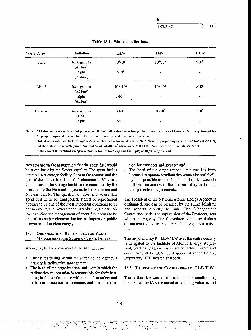
POLAND CH. 18
Table 18.1. Waste classifications.
Waste Form Radiation LLW ILW HLW
Solid beta, gamma(ALI/m3)
alpha(ALI/m3)
102-106
>102
>109
Liquid beta, gamma(ALI/m3)
alpha(ALI/m3)
10'2-102
>10'2
102-105 >105
Gaseous beta, gamma(DAC)alpha
0.1-10 10-106 >106
Note: ALI denotes a derived factor being the annual limitof radioactive intake through the alimentary canal (ALIp) or respiratory system (ALIo)
for people employed in conditions of radiation exposure, stated in separate provisions.
DAC denotes a derived factor being the concentrations of radionuclides in the atmosphere for people employed in conditions of ionizing
radiation, stated in separate provisions. DAC = ALIo/2400 m3 where value of 0.1 DAC corresponds to the ventilation outlet.
In the case of unidentified isotopes, a more restrictive limit expressed in Bq/kg or Bq/m3 may be used.
rary storage on the assumption that the spent fuel wouldbe taken back by the: Soviet supplier. The spent fuel iskept in a wet storage facility close to the reactor, and theage of the oldest irradiated fuel elements is 35 years.Conditions at the storage facilities are controlled by theuser and by the National Inspectorate for Radiation andNuclear Safety. The question of how and where thisspent fuel is to be transported, stored or reprocessedappears to be one of the most important questions to beconsidered by the Government. Establishing a clear pol-icy regarding the management of spent fuel seems to beone of the major elements having an impact on publicacceptance of nuclear energy.
18.4 ORGANIZATIONS RESPONSIBLE FOR WASTE
MANAGEMENT AND SCOPE OF THEIR DUTIES
According to the above mentioned Atomic Law:
• The issues falling within the scope of the Agency'sactivity is radioactive management;
• The head of the organizational unit within which theradioactive wastes arise is responsible for their han-dling in full conformance with the nuclear safety andradiation protection requirements and their prepara-
tion for transport and storage; and• The head of the organizational unit that has been
licensed to operate a radioactive waste disposal facil-ity is responsible for keeping the radioactive waste infull conformance with the nuclear safety and radia-tion protection requirements.
The President of the National Atomic Energy Agency isdesignated, and can be recalled, by the Prime Ministerand reports directly to him. The ManagementCommittee, under the supervision of the President, actswithin the Agency. The Committee adopts resolutionson matters related to the scope of the Agency's activi-ties.
The responsibility for LLW/ELW over the entire countryis delegated to the Institute of Atomic Energy. At pre-sent, practically all radwastes are collected, treated andconditioned at the PEA and disposed of at the CentralRepository (CR) located at Rozan.
18.5 TREATMENT AND CONDITIONING OF LLW/ILW
The radioactive waste treatment and the conditioningmethods at the IAE are aimed at reducing volumes and
184

POLAND CH. 18
preparing for safe transportation and storage to fulfillthe requirements for final disposal at the CR.
Low level liquid waste is chemically treated in a clarifi-er resulting in a volume reduction of about 100 times,and the sludge is transferred to a bitumization plant forfurther treatment. On the other hand, ILW is concentrat-ed by evaporation, and the distillate is further purifiedby ion exchange before being released. The concentrates(evaporator sludge) are conditioned by cementation, andthe radioactivity and chemistry of the decontaminatedliquid effluents are controlled before being released.Solid LLW is compacted into 0.2 m3 drums using a 12-ton press, and the biological wastes, after urea-formaldehyde conditioning, are stored in 0.05 m3
drums.
18.6 STORAGE OF RADIOACTIVE WASTE
The Central Repository for radioactive waste is a near-surface type located 90 km from Warsaw on the groundsof a former military fort built in 1905. The CR was putin operation in 1961. The geology of the site is charac-terized by boulder and sandy clay. No historical recordsregarding seismic activities in the area are available.
Most of the repository is characterized by a concretestructure of military design with roof and wall thick-nesses of 1.2 to 1.5 m, and a floor thickness of about 30cm. Within a protection trench of the fort, a moat is usedfor final disposal with a concrete cover about 20 cmthick. Only solid and solidified low and intermediatelevel wastes are stored at the CR. After 33 years of oper-ation, about 5400 m3 of wastes have been disposed of inthis repository. The cumulative activity of these wastesis 250,000 GBq (without decay), or 40,000 GBq withdecay.
waste are placed in layers that are separated by layers ofconcrete. This procedure is repeated until the moat isfilled to capacity, and the top layer is protected byasphalt.
18.6.2 Environmental Radiation Monitoring
The on- and off-site radiation monitoring system at theCR includes two basic groups of measurements:
• Radioactivity levels in environmental samples, and• On-site and off-site gamma radiation levels.
Records of measurements are made by the IAE and pre-sented annually to the National Inspectorate forRadiation and Nuclear Safety as well as to the appropri-ate local administration.
18.7 NEW REPOSITORY SITE INVESTIGATIONS
A study was initiated in Poland in the late seventiesaimed at selecting areas suitable for radioactive wasterepositories. Initially, the main attention was concentrat-ed on selecting areas characterized by rock systems suit-able for the permanent isolation of wastes. Salt beds,crystalline rocks and clay formations of considerablethickness were considered the most appropriate rocksfor an underground repository.
The study was conducted upon the request, and wascoordinated, by the National Atomic Energy Agency.Many specialists from various scientific institutions par-ticipated in the elaboration of specific issues. The inves-tigations were designed to determine potentially usefulrepository sites in three categories: (1) superficial; (2)shallow underground; and (3) deep underground (seeNos. 1-10, Fig. 18.1).
18.6.1 Storage in Concrete Bunkers
Concrete bunkers are used for temporary storage ofalpha waste and contaminated installations and devices,which will be reused. Solid alpha wastes are placed in achamber that is sealed off, after being filled, with a brickwall. Sealed sources of waste, with activities that do notexceed 4 GBq, are disposed of in one of the under-ground concrete bunkers. The access hole to this bunkeris sealed with a lead cover lid 200 mm in thickness.
Except for the alpha waste categories, the LLW is dis-posed of in the moat of the CR where the bed and wallsare made of concrete. The containers of the conditioned
18.7.1 Deep Underground Waste Repositories
An examination of geological formations that initiallyappeared suitable for the construction of deep wasterepositories and could satisfy nuclear safety require-ments led to the following selection of sites shown onFigure 18.1:
• Silurian shales in northern Poland (No. 5 );• Granites, bastard granites, crystalline Pre-Cambrian
shales in eastern Poland (No. 6); and• Triassic mudstone (No. 4).
The location of a repository within these formations
185

A 2. ffl 3. O U. B 5. • 6. 1 7 . A a
Figure 18.1. Areas selected in Poland for the possible location of a radioactive waste repository: 1 - superficial(Quaternary); 2 - shallow underground (Tertiary-Pliocene; 3 - shallow underground (Tertiary-Sarmatian); 4 - deep underground (Triassic)' 5 - deep underground (Silurian); 6 - deep underground(Pre-Cambrian); 7 - deep underground (Permian); 8 - deep underground(Permian); 9 - limits of areawith favorable climatic conditions for superficial radioactive waste repositories; and 10 - active repos-itory at Rozan.
would require the construction of deep undergroundworks.
In discussions concerning waste storage in other rocktypes, the concept of storage in salt formations was alsoconsidered. The following selections were made froman analysis of formations of Permian and Miocene age:
• Rock salt in the Baltic region (No. 7); and• Salt diapirs in central Poland (No. 8).
Information on rock salt has been revealed in varyingdegrees by wells and geophysical investigations. Theseearlier studies were conducted in terms of assessing thesalt resources for the chemical industry. Solution mining
(lixiviation) of storage cells in one of the rock-saltdiapirs was considered to be the most appropriate solu-tion.
During the period of planning for the development ofnuclear energy, a study was carried out to determine thebest waste repository policy to adopt concerning rock-salt beds in northern Poland. A method was presentedfor the prognosis of thermal effects in an undergroundrepository for highly radioactive waste and the problemsof optimizing the underground works and the storagetechnique. The repository was assumed to be located inPermian salt beds at a depth of 740 m beneath the sur-face. The average bed thickness in the area of the repos-itory is about 200 m, and the overlying formations are
186

POLAND CH. 18
anhydrides and Permian dolomite limestones. Abovethese beds are Mesozoic and Cenozoic formations withpossible water-bearing strata.
To develop the prognosis of the temperature distribu-tion, a method was proposed that is based on an analyt-ical solution to the thermal conduction equation for theindividual source (waste container). With regard to thedesign stages of the repository, this method allows oneto more rapidly assess an optimal scheme for the distri-bution of repositories. The results of this model studyshowed that the thermal impact of such a repositorybecomes apparent only after some one hundred yearsand that the impact is practically negligible.
18.7.2 Shallow Underground Waste Repositories
Further considerations were therefore limited to the con-struction of a shallow repository in clay formations. Theradioactive waste would be stored in shallow pits orlarge-diameter wells some 50-70 m under the surface.The following formations were selected:
• Krakowiec clays (Tertiary period - Sarmatian) insoutheast Poland (No. 3); and
• Spotted clays (Tertiary-Pliocene) in central Poland(No. 2).
An analysis of the population conditions and physicalmanagement was carried out at these sites.
18.7.3 Superficial Waste Repositories
The existence of outwash sands that are located in boul-der clays were selected as a favorable location for super-ficial waste repositories. The most favorable location onthe watersheds of rivers is also essential. A study wascarried out at ten locations using the methodology rec-ommended by the International Atomic Energy Agencyfor the pre-selection and selection stages. The prospec-tive areas were separated from major regions for furtherdetailed analysis. An evaluation of the usefulness of theareas selected was carried out, in relation to an analysisof geographic conditions, on the basis of the existenceof conditions that would exclude or limit the area itself.The characteristics of the areas were analyzed in termsof the following issues:
• Geological setting and hydrogeological conditions;• Geodynamical processes;
• Potential of raw materials;• Hydrology;• Meterology and climate; and• Environmental management and protection.
Most locations were concentrated in central Poland (No.1 on Fig. 18.1) within an area where favorable climaticconditions for a superficial repository prevail. The fol-lowing conditions were considered to be preclusive fac-tors:
• Presence of legally protected areas (reservations,national and landscape parks);
• Areas with planned regional limitations on physicalmanagement;
• Areas under the influence of a concentrated ground-water exploitation;
• Areas with imminent 100- and 500-year floods;• Areas where the subsurface waters are highly miner-
alized; and• Areas with shallow groundwater.
An analysis of the social and economic conditions werealso carried out in some of the locations. At the sametime, attempts were made to obtain social acceptance forlocations selected for a superficial repository.
18.8 SUMMARY
The nuclear energy development program in Poland isstill not precisely defined, but it is clear that any furtheradvancement in the field of nuclear technology cannotbe pursued without solving the waste isolation problem.For the future of the national economy, there is a needfor serious consideration of this source of energy. Anincrease in environmental protection studies is nowquite evident and results in an enforced continuation ofprevious research concerning the the location and docu-mentation of new repository sites.
The results presented in this paper are concerned pri-marily with the preselection stage. Only in the case ofsuperficial radioactive waste repositories are some ele-ments of the selection stage being investigated. Within aperiod of about ten years, the next studies will concen-trate on the choice of possible locations for undergroundand superficial radioactive waste repositories. It is evi-dent that, after potential sites have been selected, quitedifferent programs of time-consuming research will berequired for each of these types of repositories.
187

188
« * , - - • • •

CHAPTER 19
PROGRAM O F GEOLOGICAL DISPOSAL O F SPENT FUEL A N DRADIOACTIVE WASTES IN SLOVAK REPUBLIC
Jan Timul'ak
Decom Slovakia s.r.o., Trnava
19.1 INTRODUCTION
The present stage of spent fuel and high level wastemanagement is a development from the nuclear cyclestrategy of the former Czech and Slovak FederalRepublic (CSFR). This concept was based on intergov-ernmental agreements between former CSFR and theSoviet union (USSR) on cooperation and assistance dur-ing construction and operation of Czechoslovak nuclearpower plants (NPP). The cooperation program betweenCSFR and USSR provided for confirmed unpaid trans-port of spent fuel to USSR during the whole time peri-od of operation of Czechoslovak NPP's. Up to 1988,about 700 assemblies of spent fuel were transported tothe USSR.
Fulfillment of the above agreements was not fixed in theUSSR approach. First, there was a prolonged period ofspent fuel storage on CSFR territory, and after the polit-ical changes, new transport conditions, abandonment ofunpaid transport, and a decrease of assembly pieces ded-icated for transport. As a result, the Slovak Power Plantscompany decided to construct long period spent fuelstorage. Wet storage is used in this operation and itscapacity is 600 tHM (5,040 pieces of fuel assemblies).
The main reason for changing the original strategy ofhigh level waste and spent fuel management was theabandonment of unpaid spent fuel transport after thepolitical changes in the Russia Federation. With respectto the present economic situation in the SlovakRepublic, it is impossible to decide on a new strategy inthis field. Therefore, the Slovak Power Plants companydecided to solve the problem with interim storage ofspent fuel for approximately 50 years and start prepara-tion of deep geological disposal of high level wastes andspent fuel under the conditions of the Slovak Republic.
19.2 HISTORY OF PROJECT DEVELOPMENT
The history of repository development designed toaccept high level and long lived radioactive wastes andspent fuel started two decades ago. At that time theNuclear Research Institute Rez (Czech Republic) issuedsome basic policies concerning the conceptual and safe-ty aspects of a deep geological repository.
The year 1984 became a turning point for the intensifi-cation of activities towards underground facilities.Initiated by Energoproject with participation of Gas-project, and Construction Geology, the NuclearResearch Institute and other companies examined thepossibility of constructing a deep silo (over 500 m) forreactor waste from NPP Dukovany and later NPPTemelin. Even though the project was abandoned, it pro-vided valuable experience from the fields of geology,safety studies and contacts with the public.
Further activities, stimulated mainly by the need for pro-cessing waste arising from the decommissioning of NPPA-l in Jaslovske Bohunice, were more preciselydefined. They sought tools usable for evaluating theacceptability of sites, the solicitation of proper regionson the basis of archival data, and the extension of possi-bilities to provide safety analysis. The leading compa-nies performing these activities were Geoindustry,Central Institute of Geology, Institute of Geophysics,Nuclear Research Institute, Nuclear Power PlantResearch Institute, Dionyz Stur Geological Institute andothers. One of the achievements reached was a basicevaluation of the Slovak territory for purposes of sitinga deep geological repository.
It is reasonable that works aimed at the geologicalrepository were performed by a number of institutions,
189
SLOVAK REPUBLIC C H . 19
and their costs were covered from different sources.This led to a certain heterogeneity of activities and as aconsequence an incongruity and incoherence in theresults obtained. Therefore, urged by a need to initiate aprogram of spent fuel management, which arose afterthe political changes in Europe, the Federal Ministry ofEconomy of CSFR started the preparation of a technicalprogram initiating the most urgent works in 1992. Thepurpose was to concentrate available agencies in a con-sistent, centrally coordinated contract. In the course ofpreparing this task, practically all central organizationsinvolving contractors, as well as most research bodiesactive in waste management as suppliers, were involved.Firstly, the technical content of the project was definedand then, as a result of competition, the NuclearResearch Institute was appointed as coordinator.Unfortunately, due to the division of Czechoslovakia,funding of the project collapsed. To promote the prima-ry purpose of the project, in the spring of 1993, theCzech Power Company and the Slovak Power Companydecided to order a study on, "The plan for developmentof a deep geological repository" and to share its expens-es equally.
In view of the importance of the report for furtherprogress in repository development in the future, it wasdecided that the contractor should ensure an internation-al review of the prepared document. For this purpose, acontact was established with the administration of TheNuclear Cycle Division of the International AtomicEnergy Agency, which advised that the government askfor an evaluation within the Waste ManagementAssessment and Technical Review Program (WATRP).The results of the mission were attached to this study asa separate document in December 1993.
After the division of CSFR, work on development ofdeep disposal of high level wastes and spent fuel inSlovak Republic started only at the end of 1995.Because of the developments since 1993 in world-wideexperience with deep disposal, and because the originalproject was elaborated for conditions in the formerCSFR, the first step in continuing the work was the needto revise the original project for deep disposal develop-ment and adapt it to conditions in Slovakia.
19.3 PURPOSE OF PROJECT
The main goal of the revision was to specify the mainbounds among the particular tasks of deep disposaldevelopment. This means taking into account all
requirements for site selection, near-field and far-fieldinteractions, quality assurance, safety analyses, the roleof the public as well as design studies and licensingsteps under the conditions of the Slovak Republic. Therequirement of the customer was to compile a basicoverview of activities aimed at the construction of adeep repository designed for spent fuel and for longlived and high level wastes. Especially, the research,development and design phases were to be thoroughlyelaborated so that connections within each topic as wellas between different problems are respected.
The technical characteristics of solutions for each topichad to be completed with consideration for time andeconomy; however, there are some doubts about the reli-ability of both tasks. The reason is simple. Developmentof the deep repository needs a very long time (tens ofyears), and thus, it is possible to make only extremelyrough estimates of the time demands, and as a conse-quence, the economical needs of particular tasks.Furthermore, the time consumption is often dependenton non-technical issues, such as: the influence of publicacceptability of particular solutions, licensing period,changes in development procedures due to politicaldecisions, probability of receiving unacceptable resultsfollowing the repetition of a certain volume of work,consequences of changes in legislation, etc.
The next requirement of the customer was to postulatein detail a 5-year program of work respecting the pro-grams in progress, underlining within each topic themain activities that could, when postponed, retard solu-tion of other development problems, and initiating newkey tasks that have not yet been started.
The document, which is the result of the deep disposalproject revision, will serve as a guide for all necessaryresearch and development procedures that must be coor-dinated, and completely and equably answered in allaspects.
19.4 RESULTS OF PROJECT REVISION
To reach all claims during a very short period, the fol-lowing procedure has been adopted:
• a philosophy of the study was selected that consistsin parallel solutions of particular tasks by workinggroups supervised by an institution and a specialistexperienced in waste disposal;
• some comprehensive problems were defined and
190

SLOVAK REPUBLIC C H . 19
supervisors for each of them were nominated;• nearly every three weeks, coordination meetings
were organized in which the progress and resultsobtained were evaluated and critiqued, and goals forthe next period were set up; and
• the final versions of the respective parts were com-piled in this document and completed by introducto-ry chapters and annexes.
The above mentioned procedure resulted in a structureof the document which describes a gradual improvementin each problem in connection with new developmentsin the field of deep disposal as well as their adaption toconditions in the Slovak republic. It is clear mainlywhen inspecting the diagrams. The diagrams are com-plemented by commentary that should explain the con-tent of each of the activities. Its other role is to mentionproblems that could not be easily read from a diagram.The description of each particular task contains discus-sion about the economical and time aspects for the solu-tion of the topic.
The detailed 5-year plan of activities describes the solu-tion for each particular task in the development of spentfuel and deep disposal of high level waste until the year2000. The plan contains concrete data on time and econ-omy that are necessary for the deep disposal projectrealization. The main aim of the short-term plan is toshow waste producers, as well as contractors of revi-sions, an extent, a content and a cost of anticipatedworks for the preparation of the deep repository con-struction. In this way, the plan can serve as a back-ground document for planning purposes.
The basic result of the project revision, in which thesolution of the whole project is shown, is a "Diagram ofdeep repository development" (Fig.19.1). This diagramis vertically divided into the main particular tasks, fol-lowing the text of this report. Horizontal divisions indi-cate a time succession of activities in each topic and, toa certain level, it also parallels the implementation of themain works. It should be mentioned that the diagram issignificantly simplified and that the time axis is not lin-ear, which means that there is no correspondence withreal timing of the topics being considered.
The diagram shows one interesting point. Practicallyevery particular task, such as research and development,consists of several phases. They include construction,operation and closure of a facility, and they even includesome data on the course of a final evaluation of safety
and reliability of the system. When considering that thisconcerns a time period of more than one hundred years,then the role of a coordinator of all activities, credibleworking groups, and uncompromising control, supervi-sion and licensing bodies must be stressed.
The main branch of the diagram is connected to a topic"Design activities and construction". This line compris-es all principal decision processes. It also includes thekey outcomes, design studies and designs, and construc-tion procedures. It can be stated that the other main par-ticular tasks provide the necessary data for decisions ofa designer concerning the final solution of an under-ground repository and auxiliary facilities.
Geological works are connected to an evaluation of themobility of contaminants in the geological system (farfield interactions). Activities contained in this double-topic are focused on selection and verification of thesuitability of a site and corresponding geological systemfor construction of a repository. They also summarizeinput data for safety analyses of long term behavior ofthe system.
Studies of the behavior of engineered barriers, finalwaste forms, packages, overpacks, sealing and fillingmaterials, and underground constructions (near fieldinteractions) are aimed at a choice of an optimum com-position of barriers and to evaluate the effectiveness oftheir retention ability for radiocontaminants. Otherspecies of disposed materials are to be evaluated as well(source term). The results of these studies provide pro-posals for material composition of repository construc-tion addressed to designers, and data dealing with veloc-ity, mechanisms, and probability of release of immobi-lized species.
The task of safety analyses is to summarize and evaluateall data received in the course of geological investiga-tion and research, during construction and operation ofa facility, at waste treatment processes. In addition, theylay down limits and conditions that any constructionstructure shall fulfill. Elaboration of safety analysis isthe necessary condition for any licensing procedure, andthus, it can be considered to be the absolute key topic ofrepository achievement.
Quality assurance belongs to a group of activitiesdesigned to secure the maximum level of biospherepreservation. Its aim is to work out programs of controland supervision of all activities connected with reposi-
191

2000 2005
PUBLIC
INVOLVEMENT INFORMATION SYSTEM INFORMATION SYSTEM INFORMATION SYSTEM
' ''">=•(
LEGISLATIVECONNECTIONS
LICENCEPROCEDURE
SOURCE TERMNEAR-FIELDINTERACTIONS
IDESIGN WORKS|ANDIICONSTRUCTION
FAR-FIELDINTERACTION.GEOLOGIC WORKS
UNDERGROUNDLABORATORY
ISAFET||ANALYIISAFETY
iLYSES
IQUALI1
IIASSURIIQUALITY
URANCE
MONITORING
LAW- DEMANDS - CRITERIA - REGULATION LAW • DEMANDS - CRITERIA - REGULATION
WASTECHARACTERISTICS
PROJECT STUDY
E.I.A.
HOSTENVIRONMENTSELECTION
BEHAVIOR STUDY
•SAFETY1
STUDY
CRITERIA
UJD, MHMZd, MZP
CRITERIAPROPOSA
*
T
r D
LICENCE
1ONTRACTPROJEC
1 * •
•. D
BARRIERSOPTIMAUZATION
1
CONTRACTSAFETY
ANALYSIS
STUDY SITE AND CANDIDATESITE SELECTION ANDVERIFICATION
UNDERGROUND
CONCEPT
>
HOST. STRUCTURE
VERIFICATION
SITE SELECTION
VERIFICATION
SAFETY STUDY1
1
u a <IA
SITE DECISIONPROCEDURE
rM
9
1
D
1 '
UJD, MHMZd, MZP
SITE DECISIONANDCONSTRUCTION
STUDY OF DEEPGEOLOGIC
REPOSITORYCLOSUREPROCEDURAL
PROJECT
1
D
;
UNDERGROUND
CONSTRUCTION
RESEARCH
REALIZATION
PRELIMINARYSAFETYANALYSIS
|| QUALITY ASSURANCE QUALITY ASSURANCE
MONITORING MONITORING
1770m•v
CO
n
Figure 19.1a. Diagram of repository development. DI

2030 2060
INFORMATION SYSTEM INFORMATION SYSTEM INFORMATION SYSTEM
LAW- DEMANDS - CRITERIA - REGULATION
OJ
1
TRIAL RUN
UJD, MHMZd, M2P
DEEP GEOLOGIC REPOSITOR'
CONSTRUCTION
OPERATIVE PROJECTS
RESCUE OF THE UNDESIRABLE IN-SITUANISOTROPY.MONITORINGNETWORK SUPPLEMENT
APPROVAL, TRIAL RUNDECISION
I
I
u
BASICMONITORING
UJD, MH
MZd,M2P
OPERATION END
DECISION
STUDY OF ENGINEERED BARRIERREAL-TIME BEHAVIOR
DEEP GEOLOGIC REPOSITORY
CONSTRUCTION
DEEP GEOLOGIC REPOSITORY CLOSUR
PROJECT
VERIFICATION OF IN-SITUMODEL SOLUTION
PRE-OPERATIONSAFETY REPORT
I-»•
IFAR-FIELD MONITORING
INFORMAIIUNHOK IH tUhtHGEOLOGIC REPOSITORY
CLOSURE, CONTROL
D
T3
2
POST-OPERATIONAL
SAFETY REPORT
QUALITY ASSURANCE
Im-aCD
n
MONITORING
Figure 19.1b. Diagram of repository development (continued).n

INFORMATION SYSTEM
LAW- DEMANDS - CRITERIA - REGULATION
2
REAL SYSTEMEVALUATION
POST-OPERATION' PERIOD
UJD, MH
MZd, M2P
MONITORINGSYSTEMEVALUATION
1 p..-
EVALUATION OFRESCUE SPACEBEHAVIOR
1MONITORINGSYSTEMEVALUATION
i
D
FINAL SAFETY
REPQRT
^ f INSTITUTIONAL^ T CONTROL
UJD, MH
MZd, M2P
MONITORINGSYSTEMEVALUATION
\ '
D
I
FINAL SAFETY
REPORT
UNLIMITED SITE USE
QUALITY ASSURANCE
I73m•D
U3
n
Figure 19.1c. Diagram of repository development (continued).n
SLOVAK REPUBLIC CH. 19
tory development and construction. The goal of theseprocedures is to eliminate risks mainly connected withthe so called "human factor".
The licensing processes are included in the particulartask "legislation connections" because these processesinfluence significantly all other steps of deep disposaldevelopment. They permit each subsequent activity;they may on the basis of some independent evaluationprevent the implementation of such steps. Actually, theyare connected to the formulation of claims, require-ments, and methods. Sometimes they even set the con-ditions, and the licensing decisions are issued using aninterpretation of these limits and recommendations for aconcrete system.
Monitoring in the diagram (Fig.19.1) is considered to bean independent, permanently valid particular task,although in the study, it is described in other particulartasks. Deep disposal monitoring includes a number ofsteps: radiochemical, hydrological and hydrogeologicalmonitoring of sites from the beginning of research; geo-logical monitoring of a rock structure; measuring theradiological impacts to personnel and the public; record-ing the changes of state and behavior of barrier materi-als; meteorological records; observation of destructiveand corrosion phenomena, etc. Interpretation of themonitored data is one of the basic conditions requiredfor closure and release of the facility.
The results of particular tasks of the public may by itsconsequences not only influence but completely changeany technical decision. Public involvement in theprocess of developing a deep repository has at least twoaspects. First, passive, which is interpreted as an infor-mation campaign about the repository system, design,construction, safety, risks and advantages of its realiza-tion. Second, active, which is an effect of public mean-ing and also the design of the repository by independentopinions and evaluations. A first-rate program on com-munication with the public may simplify the achieve-ment of the repository; on the contrary ignoring thenecessity of reaching a concensus with the general pub-lic can completely eliminate the project.
The revised document for a project of deep disposaldevelopment is seen first of all as a methodological doc-ument. Particular problems of the project may differ intheir content, but the approach to their solution has somecommon features, such as long-term considerations andthe principle of conservatism.
The general feature of systems of radioactive wastemanagement is the long-term consideration of allprocesses, activities and applicable phenomena. This isshown by the fact that partial issues are converted intomaterial outputs after a long period, often reaching tensof years. Time factors bring a number of questions to anevaluation of the behavior of repository elements. Toanswer them requires finding unusual and substituteways, e.g. mathematical modeling, studies of natural orman-made analogues.
An indirect interpretation used for waste form behaviorduring disposal is rather lengthy, and it involves someuncertainty. To reach a desired level of safety and func-tionality of the system, a principle of conservatism isapplied in any evaluations. This means that those phe-nomena, or some combination, are considered that bringless favorable results.
The important fact in the methodology of deep disposaldevelopment is to have an objective approach to anystep, activity or decision. That kind of solution is pro-vided by preparation and realization of quality assur-ance programs. The main part of those programs is mul-tiple opinions and evaluations of solutions. There is atendency to leave out this demand. This is dangerousfrom two points of view. Any incorrect decision maycause irreparable damages even resulting in cancelingthe previous results, or the process of repository devel-opment may be suspended by a qualified oppositionbecause of the inability technically to defend chosensolutions.
19.5 CONCLUSION
The revision of this project is the result of the work of agroup of employees of the following institutions:DECOM Slovakia Ltd., Nuclear Power Plant ResearchInstitute, Geologic office of Slovak Republic and EPGInvest Ltd. It has been worked out under the technicaland editorial coordination of the DECOM Slovakia Ltd.,however, separate authors are responsible for their ownsections. All of those involved have attempted to devel-op an approach in the most objective way.
The goal of the activities was to perform a revision ofthe project from the year 1993, in which must be includ-ed the deep disposal development of the former Czech-oslovakia, to incorporate the new world results of thisfield development, to modify it for conditions of Slo-vakia, and to add the economic and time considerations
195

SLOVAK REPUBLIC CH. 19
to the technical solution. The determination of concrete A summary of the above mentioned data in one docu-activities through the year 2000 was an inseparable part ment creates the material, which defines concrete activ-of this methodological document. Each particular task ities and the needs of finance to assure the required out-of the project contains ideas about concrete activities, put from a solution for a deep repository developmentfinancial costs and solutions as well. under the conditions of Slovakia.
196

CHAPTER 20
GEOLOGICAL ASPECTS OF SITE SELECTION FOR LOW AND INTERMEDIATELEVEL RADWASTE REPOSITORY IN SLOVENIA
Borut Petkovsek1, Dusan Marc2, and Igor Osojnik3
1. National Civil Engineering Institute, Ljubljana, Republic of Slovenia2. Agency for Radwaste Management, Ljubljana, Republic of Slovenia
3. Slovenian Nuclear Safety Administration, Ljubljana, Republic of Slovenia
Abstract. According to the guidelines for a low and intermediate level radwaste repository site selection in Slovenia,the siting process has been divided into four steps. The first three steps of the surface site selection were completedin 1993. A set of the most exclusionary geological criteria to be applied in selecting the surface site is described.Some reasons for the failure of this process are also described. Since the fourth step was stopped due to strong pub-lic opposition, an alternative of underground disposal is now being considered. In 1994, the Agency for RadwasteManagement started the preparation of basic guidelines for underground repository site selection. Joint recommen-dations, that consider both surface and underground site selection parameters, are now being developed in theSlovenian Nuclear Safety Administration.
20.1 INTRODUCTION
The guidelines for the selection of a low and intermedi-ate level radwaste (LILW) disposal site were setup in1991. The guidelines that were announced includedrules according to which, under the given urban andsocial conditions, the most suitable site for the shallowground disposal of LILW in Slovenia would be selected.Both the existing world-wide experience and the nation-al regulatory conditions in Slovenia were considered increating these guidelines.
In selecting disposal sites, it was necessary to have adetailed knowledge of the process of migration of cont-aminants into the biosphere. Slovenia has a very sophis-ticated geological and tectonic setting dominated by var-ious combinations of geological structural elementssuch as: faults of different type and age, overthrusts,folds, naps and lateral transformations of different litho-logic units. In most cases, it was very difficult to deter-mine the migration of radionuclides in undergroundwater. Thick layers of impermeable rocks are the onlyreliable natural barrier in such geological and hydroge-ological conditions.
However, the requirements given by the guidelines arethat a shallow disposal site is to have rocks of low per-meability in the basement, and a distance to the under-ground water table that is as large as possible. Sites withthese geological conditions, such as saturated clay
marls, were the only ones selected as being acceptable.These rocks, regardless of fracturing in neighboring lay-ers, provide a sufficient natural barrier to prevent migra-tion of radionuclides.
20.2 SITE SELECTION PROCESS FOR LILW
The procedure used in selecting disposal sites was divid-ed into three steps containing 43 criteria. In a finalfourth step, the technical confirmation was based on adetailed field examination of the geology, hydrogeology,and seismology of the site. Each step was terminated bya presentation to the public of the results.
In the first step, unsuitable areas were excluded by tak-ing into consideration certain exclusion criteria, such as:national parks, urban zones, ground water resources,presence and location of active faults, geothermal areas,flood areas, presence of ores, minerals, oil, gas,hydraulic conductivity, soil composition, thickness andextent of geologic units.
In the second step, the remaining acceptable areas wereevaluated according to land use, water resources, seis-mic and geological criteria, so they could be furtherreduced to so called potential sites.
In the third step, several of the most suitable of thepotential sites were chosen by comparing their locationson the basis of the following criteria: population, eco-
197
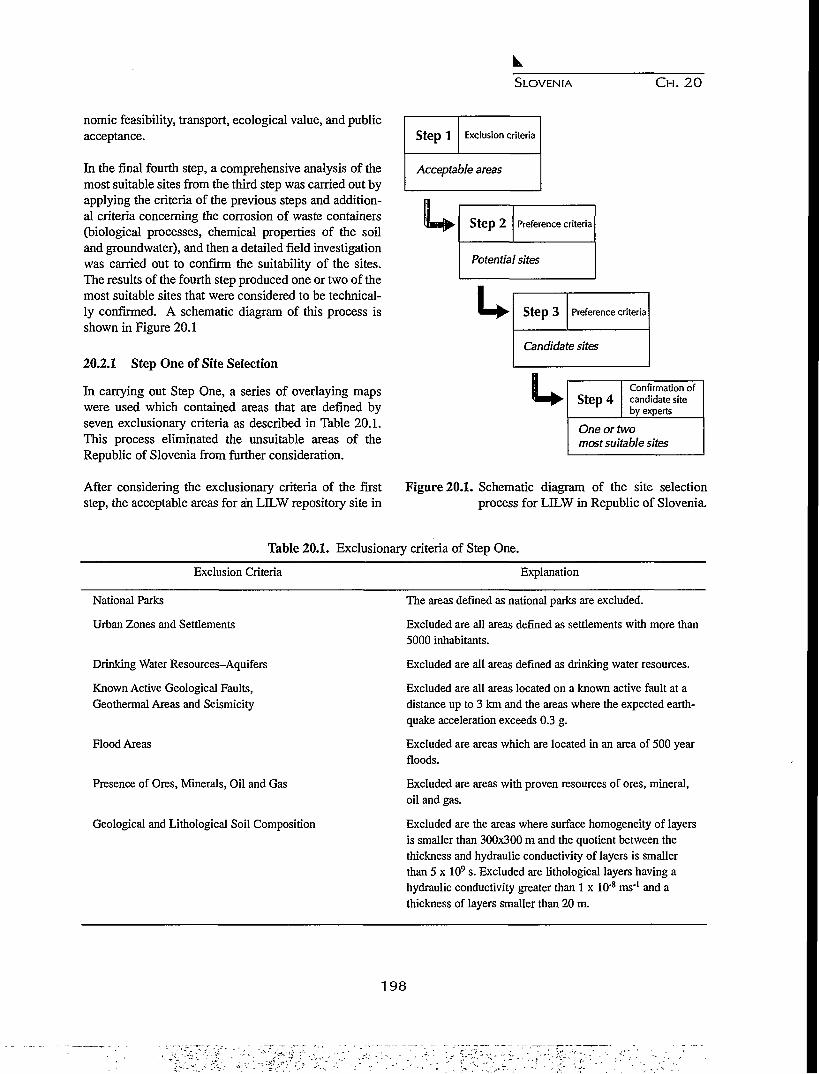
SLOVENIA CH. 20
nomic feasibility, transport, ecological value, and publicacceptance.
In the final fourth step, a comprehensive analysis of themost suitable sites from the third step was carried out byapplying the criteria of the previous steps and addition-al criteria concerning the corrosion of waste containers(biological processes, chemical properties of the soiland groundwater), and then a detailed field investigationwas carried out to confirm the suitability of the sites.The results of the fourth step produced one or two of themost suitable sites that were considered to be technical-ly confirmed. A schematic diagram of this process isshown in Figure 20.1
20.2.1 Step One of Site Selection
In carrying out Step One, a series of overlaying mapswere used which contained areas that are defined byseven exclusionary criteria as described in Table 20.1.This process eliminated the unsuitable areas of theRepublic of Slovenia from further consideration.
After considering the exclusionary criteria of the firststep, the acceptable areas for an LILW repository site in
Step! Exclusion criteria
Acceptable areas
H
I* Step 2 Preference criteria
Potential sites
u Step 3 Preference criteria
Candidate sites
u Step 4Confirmation ofcandidate siteby experts
One or twomost suitable sites
Figure 20.1. Schematic diagram of the site selectionprocess for LILW in Republic of Slovenia.
Table 20.1. Exclusionary criteria of Step One.
Exclusion Criteria Explanation
National Parks
Urban Zones and Settlements
Drinking Water Resources-Aquifers
Known Active Geological Faults,Geothermal Areas and Seismicity
Flood Areas
Presence of Ores, Minerals, Oil and Gas
Geological and Lithological Soil Composition
The areas defined as national parks are excluded.
Excluded are all areas defined as settlements with more than5000 inhabitants.
Excluded are all areas defined as drinking water resources.
Excluded are all areas located on a known active fault at adistance up to 3 km and the areas where the expected earth-quake acceleration exceeds 0.3 g.
Excluded are areas which are located in an area of 500 yearfloods.
Excluded are areas with proven resources of ores, mineral,oil and gas.
Excluded are the areas where surface homogeneity of layersis smaller than 300x300 m and the quotient between thethickness and hydraulic conductivity of layers is smallerthan 5 x 10⁹ s. Excluded are lithological layers having ahydraulic conductivity greater than 1 x 10'8 ms"1 and athickness of layers smaller than 20 m.
198

SLOVENIA C H . 20
Slovenia were identified. The potentially acceptableareas were those that had not been excluded accordingto any criterion of Step One. All of these areas wereconsidered to be equivalent, i.e., the acceptable areashad not been assessed and evaluated. Figure 20.2 showsthe locations of the acceptable areas after the applicationof the first step.
20.2.2 Step Two of Site Selection
In carrying out Step Two, the preference criteria weredivided into four groups: geological, seismic, land use,and potential water management. These criteria werethen applied to the acceptable areas selected in the firststep.
The following geological preference criteria wereapplied:
• Presence of groundwater;• Site seismicity;• Presence and vicinity of active faults;• Exploitation of ores/minerals, oil and gas;• Areal extent of host rock;• Thickness of rock mass;• Soil instability;• Erodibility;
• Rock composition and hydraulic conductivity;• Angle of slopes; and• Radionuclide paths to the biosphere.
The result was the selection of 36 potential sites occu-pying a total area of approximately nine km2.
The examination of the potential locations was per-formed at the end of the theoretical studies to verify theprocedure, and to determine discrepencies in the resultsobtained. This examination resulted in an expert con-clusion that: (a) five locations are not suitable for theconstruction of a repository, and (b) another five loca-tions are only suitable for a tunnel type repository andnot for a surface type as previously envisioned. Onepotential site, suitable for both types of repository, wasalso identified and considered in further analysis.
The results of the second step of surface repository siteselection were reviewed by a group of experts that con-firmed the accordance of the procedure with the guide-lines.
20.2.3 Step Three of Site Selection.
In the the third step, five candidate sites were selectedamong 36 potential sites from the second step. The
O Acceptable areasQuaternary
I I TertiaryCretaceousJurassicTriassicPaleozoicIgneous rockMetamorphic rocksMain faults
0 10 20 30km
Figure 20.2. A generalized geological map of Slovenia with acceptable areas after the application of Step One.
1 9 9
.•' *•? "

SLOVENIA C H . 20
method of assessment was based on the repeated use ofthe criteria from the first two steps. In addition, prefer-ence criteria concerned with economic and technicalfeasibility, transport, and social acceptability were con-sidered as well.
One of the selected sites was found to be suitable for asurface repository, two, for a tunnel repository, and theremaining two sites were appropriate for either type ofrepository, surface or tunnel. The main geological char-acteristics of the sites are summarized in Table 20.2.
In accordance with the practice from previous steps inthis procedure, the results were presented to the public.The presentation was not successful and has provoked
strong disapproval within the local communities. Theirrepresentatives declared that waste disposal in the vicin-ity of their communities was not acceptable. It was evi-dent that public acceptance of the candidate locationscould not be achieved. Therefore, it was impossible toproceed to the fourth step in which the most suitablelocations could be verified and approved by the experts.The project was stopped.
20.3 DID APPLICATION OF GEOLOGICAL CRITERIA
INFLUENCE AN UNSUCCESSFUL SURFACE
REPOSITORY SITE SELECTION?
It is clear the natural site characteristics play an impor-tant role in the selection process for a radioactive waste
Table 20.2. The main gelogical characteristics of the sites.
Sitel Site 2 Site 3 Site 4 Site 5Main GeologicalCharacteristics
Surface Tunnel Tunnel Surface or Surface orRepository Repository Repository Tunnel Repository Tunnel Repository
H
0
S
TI
R
0
C
K
Rock Type
Permeability (m/s)
Relative Porosity (%)
Thickness of Layer (m)
Areal extent of RockMass (ha)
Angle of Slope (°)
Sandy marl
lO-MO"11
22
300-400
11
10-20
Erodibility (mm/300 yrs.) 4.2-5.4
Point Load Index Is
(50) MN/m2
Unconfined Compres-sive Strength (MPa)
Natural VolumeWeight (KN/m3)
0.87-1.94
17.17-42.71
20.95
Sandy marl
10"9-10-u
22
300-400
332
5-20
3.2-7.5
0.87-1.94
17.17-42.71
20.95
Sandy marl
io-9-io-»
22
300-400
104
5-20
6.4-8.6
0.87-1.94
17.17-42.71
20.95
Marl
10- u <K<10- 9
20-33
50-400
19
10-15
5.4-6.4
0.09-0.31
1.99-6.73
18.22-19.43
Marl
10" u <K<10- 9
20-33
50-400
28
10-20
4.2
0.09-0.31
1.99-6.73
18.22-19.43
Distance from ActiveFaults (km)
Max. Expected HorizontalAcceleration in a TimePeriod of 1000 years (cm/s2)
Max. Expected LocalIntensivity in a Time Periodof 1000 years (MCS)
3-4
190
8
3-4
190
7-8
3-4
190
7-8
3-4.6
250
3-4.6
250
200

SLOVENIA C H . 20
repository site, and that a site within an appropriate geo-logical environment is, to a great extent, based on geo-logical conditions.
But geological criteria, applied to the process of select-ing a surface repository site in Slovenia, used only prop-erties of the geological barrier and took no account ofthe other two barriers, i.e., conditioned waste and engi-neered barriers. In other words, the objective of findinga site for a surface repository was to find a location withgeological properties (natural geological barriers),where engineered barriers would not necessarily beused to achieve the safety standards. This was certain-ly the most economic way for repository construction,but on the other hand, the site selection was exception-ally difficult.
The siting process applied highly quantitative exclu-sionary or preference geological criteria, i.e., geologicalcriteria were stated with numerical values of the geolog-ical parameters, that made the whole siting process veryinflexible. Some geological criteria, according to their"importance" (according to the size of the excludedareas in surface repository site selection) are presentedand described in the following.
The criterion of "active faults" as a single tectonicexclusionary criterion has eliminated 97% of Sloveniafor the purpose of siting a repository. To meet this cri-terion, areas located in the vicinity of a known activefault at a distance up to three km were unsuitable.
Considering the same criterion in the second step, i.e.,presence and vicinity of active faults, acceptable areasfrom the first step ranged over the following distances:
• Unsuitable sites, where the site was to be located on,or near a fault, at a distance up to 3 km;
• Less suitable sites, where the distance from the faultis 3 to 8 km; and
• Suitable sites, where the distance is greater than 8km.
It should be noted that up to the third step, the workincluded office work only, and no site investigationswere performed to confirm activity of the faults.
Although Slovenia lies in a seismic territory, and tec-tonic causes of seismic activity, i.e. surface faults, aredistributed all over Slovenia, there is a basic question(that could be discussed) whether the application of auniform step-off distance is a matter of policy rather
than being grounded on technical principles. Withoutdetailed site investigations, it is difficult to select suit-able locations, and the geological properties of specificsites must first be confirmed through field investiga-tions.
According to the criterion for "Active faults", theWAMAP mission5 recommended that at an early stage,it is important to decide on the definition for an activefault and the significance that rock structure could haveon the integrity of a repository over its 300-year assess-ment period. It is necessary to have a single representa-tive data base, or set of maps, supporting the interpreta-tion and application of this criterion.
A similar situation occurred in the first step in connec-tion with the "Lithology" criterion, where rocks with ahydraulic conductivity greater than 10"8 m/s, a thicknessof layers less than 20 m, and a seismicity where earth-quake accelerations greater than 0.3 g would be expect-ed, were recognized as unsuitable. In further analysis,the Lithology of acceptable areas was compared consid-ering the preference criteria "Areal extent of host rock"and "Thickness of rock mass", where the area suitabili-ty increased with extent (greater than 300 x 300 m, i.e.,9 ha) and layer thickness (more than 20 m). Again, thissite analysis only involved office work. No field investi-gations, to confirm exclusive parameters for the rocks,was made.
In considering the preference criteria "Site seismicity",acceptable areas ranged between unsuitable (where theexpected earthquake accelerations amax exceeds 0.3 g fora period of 1,000 years), less suitable (amax = 0.15 to 0.3g) and suitable (amax is less than 0.15 g). The maximumhorizontal ground acceleration for the territory ofSlovenia was evaluated with a probabilistic seismic haz-ard analysis.
The mission report5 suggested that in general, an appli-cation of highly quantitative exclusion or site preferencecriteria, especially at an early stage of the selectionprocess, was not recommended.
Quantitative criteria, as applied in the siting process andas described above, can only be used where quantitativedata are available to justify their use, i.e., data confirmedby site investigations. Much of existing technical data isregional (non-site specific) and qualitative in nature aswell. Some criteria, used in the first (exclusionary) stepsimply assume certain site specific data, which wouldonly be available in the necessary detail after a careful
201

SLOVENIA CH. 20
site investigation. Such criteria should therefore be leftto the appropriate later steps in repository siting5.
It is very important to recognize the uncertainties inunderstanding the geology during the siting process,when data are based only on office studies. The actualsite conditions may be significantly different from thoseenvisaged, and as a result, the site selection processmust remain flexible enough in order to accomodateunexpected features. More confidence can be placed insites selected in a location where the geological struc-ture is non- or less complex.
20.4 NEW APPROACHES
According to the fact that the necessity for the final dis-posal of low and intermediate level radioactive wastes isgrowing, the final location of the disposal site should beselected within the next five to ten years. The existingwastes are temporarily stored in interim storage facili-ties located at the Krsko nuclear power plant.
It is obvious that problems concerning final disposal ofLILW should be solved in a satisfactory manner in thenear future. Solutions for this' problem are beingsearched for in the following directions:
1. In verification, new estimates and corrections of thethree most exclusionary geological criteria (activefaults, seismicity, and hydrogeological parameters),but the most important features have been revealed inthe application to sites for final waste disposal.
2. In considering the newest techniques and technolo-gies that have been developed in disposing of, andprotecting, radwastes in the developed countries, andin reconsidering geological criteria in this new light.
3. In taking into consideration the possibility of under-ground waste disposal of LLLW in geological struc-tures, and in this way minimizing the risks arisingfrom the seismicity and activity of fault zones.
In the analysis of the reasons for failure in the first cam-paign, it appeared that there was a bad coordinationbetween experts in the different fields of science. Forexample, geologists considered "impervious" rock asthe only suitable rock for a disposal site, regardless ofthe possibility of using engineered barriers (such as,canisters, filling materials, etc.). It is well known thatover a period of 300 years, which is the time necessaryfor the radioactivity to decay to normal levels, it is pos-sible to produce effective engineered barriers.Therefore, the requirement for an "impermeable" base-
ment beneath the deposit is no longer necessary. On thecontrary, in some repositories, such as Centre de l'Aube,a permeable basement is part of the design of the facili-ty-
The Agency for radioactive waste disposal in Sloveniahas also noted this deficiency from the first campaign.The new approach was therefore to provide some basictechnology to the experts who don't have much experi-ence in dealing with problems of packing and deposi-tion. In this way, the Agency expected to ameliorate thecooperation of these experts with that of others.
In accordance with this new policy, the Agency has redi-rected geological experts to review the new technologiesin the field of radwaste disposal in the developed coun-tries. A series of such reviews have been carried out inwhich the first aim has been achieved; the geologicalexperts of today are well acquainted with the technolog-ical possibilities and requests for construction of sur-face, or underground, disposal facilities. In addition, theAgency has made it possible for some of the experts tovisit existing sites, and to meet other geologists andexperts in other fields of science at international confer-ences. In this way, our geologists not only gathered newdata, but also established contacts with colleagues fromdifferent European countries, exchanged opinions andlearned new ways of thinking. It was especially usefulfor us to learn of unpublished experiences (both goodand bad) that led to the solution of problems on multi-national projects (such as the underground laboratoriesat Mol in Belgium, Grimsel in Switzerland, etc.).
Based on this new knowledge, a set of six possible typesof disposal facilities has been defined for Slovenia,which include geological and rough technological con-ditions. They provide a basis for new considerationsand estimations in carrying out campaigns of field inves-tigations.
The existing criteria from the first campaign have beenthoroughly reexamined. The result is a new approach inthe evaluation of the exclusionary criteria. The philoso-phy has changed; the elimination of a site or a region onthe basis of a certain criterion should be based on director indirect evidence.
There is another novelty in our way of thinking; we nolonger look for the geologically best location, but for allacceptable locations. In this way, these locations arealso available for analysis using other necessary criteria.We no longer have criteria for site selections or the elim-
202

SLOVENIA CH. 20
ination of territories, but guidelines that can give us anindication of possible problems. This approach does notlimit our decisions in advance, and thus enables a moreflexible treatment of the site selection process.
Since the site selection process for a surface repositoryhas been stopped, this new approach is more likely togain public acceptance by disposing of radioactivewastes in an underground facility.
The expansion of the site selection program to includean underground disposal facility gives us another possi-bility, and is the result of the new approach over the lastfew years. New geological guidelines for undergroundlow and intermediate level waste disposal have beenmade and revised, and on this basis, new geologicalguidelines for surface disposal of LILW have also beenremade.
Since some geological criteria are more important andcan be more applicable to underground than to surfacerepository site selection (or vice versa), the proposedcriteria differ, in many respects, from those for surfacesite selection. With regard to seismicity for example,underground structures are less susceptible to seismicdisturbances than surface structures due to the fact thateffects from earthquakes diminish with depth. Differenttransport pathways for radionuclide migration throughgroundwater to the biosphere should be considered inboth site selection processes as well.
By placing the disposal system underground in rockmeans, on the one hand, having the possibility to mini-mize the influence of the most selective criteria used fora surface repository; and on the other hand, providing anunderground disposal facility that, hopefully, would bemore acceptable to the public.
The new proposed guidelines for underground LELWdisposal consist of the following main parameters. (Weare presenting them here to show the differences withthe first criteria used in the selection process for a sur-face site.)
• Geological rock structurevolumesimplicity
• Lithology• Hydrogeological conditions
- permeabilityhydraulic gradient
• Migration
geochemical properties of rock and soilgeochemical properties of groundwater
• Active endogenetic processesseismicity
- recent fault movementsvolcanoes
• Rock disturbancehuman reasonsnatural reasons
• Potential resourcesvalue
- genesistechnology
• Geomorphologic stabilitysurface stabilitywater degradation processesextreme climates
• Geomechanical conditions
The Agency for radwaste disposal, being responsible forthe site selection process in Slovenia, will have to usethis new approach and also help it to find its way to thepublic. Reports of all studies made are available in theCentral Technical Library, and summaries of these stud-ies are translated into English. This enables all con-cerned to be kept informed about the dangers, scientificapproaches, and other work done on prevention and onsite location for a disposal facility.
REFERENCES
1. Faculty for Architecture, Civil Engineering andGeodesy, Department of Civil Engineering andGeodesy, Site Selection Repository Low andIntermediate Level Radwaste in Slovenia Step 2research, Seismicity, March 1991.
2. Geological Survey Ljubljana, Institute of Geology,Geotechnics and Geophysics, Site Selection Repo-sitory Low and Intermediate Level Radwaste inSlovenia Step 2 research, Conclusions, June 1991.
3. Geological Survey Ljubljana, Institute of Geology,Geotechnics and Geophysics, Site Selection Repo-sitory Low and Intermediate Level Radwaste inSlovenia Step 3 research, Geological Estimationsites, June 1992.
4. Geological Survey Ljubljana, Institute of Geology,Geotechnics and Geophysics, Geological Guidelinesfor Site Selection of an Underground Disposal ofLILW, Ljubljana, 1995.
203

SLOVENIA C H . 20
5. IAEA, WAMAP Mission to the Socialist FederalRepublic of Yugoslavia, Travel Report, April 1991.
6. B E , Low and Intermediate Level Radwaste Repo-sitory Site Selection in the Republic of Slovenia,Steps 1, 2, 3, Ljubljana, 1990,1992, 1993.
7. Jeran, M., Radioactive Waste Repository SiteSelection in the Republic of Slovenia, 1. Meeting ofthe Nuclear Society of Slovenia, Bovec, June 1992.
8. Republic Administration for Nuclear Safety, Guide-lines for the Low and Intermediate Level RadwasteRepository Site Selection in Slovenia, Revision 0,February 1990.
9. Republic Administration for Nuclear Safety, Guide-lines for the Low and Intermediate Level RadwasteRepository Site Selection in Slovenia, Revision 1,September 1991.
204

CHAPTER 21
RADIOACTIVE WASTE MANAGEMENT IN SPAINM A I N ACTIVITIES UP TO THE YEAR 2000
Carlos del Olmo
Empresa Nacional de Residuous Radioactivos, S.A., Emilio Vargas, 7-28043Madrid, Spain
21.1 INTRODUCTION
In 1995 there were nine nuclear power stations in oper-ation in Spain with a total capacity of 7.4 GW, supply-ing about 36% of the Spanish electrical energy. At pre-sent, spent fuel from the nuclear power plants is storedon site in pools constructed for this purpose. As of theend of 1993, there were 1457 tU of spent fuel.
The estimate of the total volume of high level wastes,spent fuel, that will have to be managed in Spain is upto 11,700 m3 (40 years of expected life). Total volumeof LLW is expected to be about 200,000 m3 of whichabout 137,000 m3 will be from the dismantling of powerplants.
The strategy and main activities for the definitive dis-posal of high level, long lived wastes are given in theGeneral Radioactive Waste Plans (GRWPs). Followinga period of intermediate storage of these wastes, theirtransport and encapsulation, they will be disposed of ina deep geological formation. Transport of the spent fuelwill be carried out by ENRESA as the responsibleauthority, either using the company's own resources orthrough specialized firms.
Waste conditioning or encapsulation will be carried outat a plant that is planned to be constructed on the samesite as the disposal facility. The technique to be used fordisposal will be based on a programme of study,research and international co-operation.
Disposal of LLW, will continue in the "El Cabril" facil-ity, which has been in operation since 1992.
The legal framework governing radioactive waste stor-age facilities and radioactive or nuclear installations inSpain is established by the Nuclear Energy Act 25 of
1964 and the Regulations on Nuclear and RadioactiveInstallations of 1972.The "Consejo de Seguridad Nuclear" (CSN), theSpanish Nuclear Safety Council, was constituted in1980 as an organization existing under Common Law,independent from the Central State Administration.CSN has its own legal standing and corporate assetsindependent from those of the State, and is the onlybody in Spain with responsibility in the fields of nuclearsafety and radiological protection.
The management of radioactive wastes in Spain isundertaken by "Empresa Nacional de ResiduosRadioactivos, S.A." (ENRESA), the Spanish nationalradioactive waste company, constituted in 1984. Eightypercent of the company is held by the Spanish Centrefor Energy, Environmental and Technological Research(CIEMAT), previously known as the "Junta de EnergiaNuclear" (Nuclear Energy Council).
21 .2 LOW AND INTERMEDIATE LEVEL WASTES
The strategy applied to low and intermediate levelwastes continues to be based on a one-to-one relation-ship between the disposal facility and the wastes them-selves. Two major courses of action have been estab-lished. The first includes the conditioning, transport andcharacterization of radioactive wastes and correspond-ing acceptance criteria, as well as the inspection criteriaand procedures required to guarantee compliance. Thesecond includes the design, construction and operationof the disposal facilities.
ENRESA was awarded a Provisional Operating Permitfor the Extension to the Nuclear Installation for theDisposal of Solid Radioactive Wastes located in SierraAlbarrana by a Ministerial Order issued on 9th October1992. As a result of this award, the installation in ques-
205
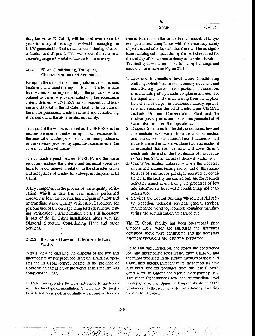
SPAIN CH. 21
tion, known as El Cabril, will be used over some 20years for many of the stages involved in managing theLDLW generated in Spain, such as conditioning, charac-terization and disposal. This waste constitutes a newoperating stage of special relevance in our country.
21.2.1 Waste Conditioning, Transport,Characterization and Acceptance.
Except in the case of the minor producers, the previoustreatment and conditioning of low and intermediatelevel wastes is the responsibility of the producer, who isobliged to generate packages satisfying the acceptancecriteria defined by ENRESA for subsequent condition-ing and disposal at the El Cabril facility. In the case ofthe minor producers, waste treatment and conditioningis carried out at the aforementioned facility.
Transport of the wastes is carried out by ENRESA as theresponsible operator, either using its own resources forthe removal of wastes generated by the minor producers,or the services provided by specialist companies in thecase of conditioned wastes.
The contracts signed between ENRESA and the wasteproducers include the criteria and technical specifica-tions to be considered in relation to the characterizationand acceptance of wastes for subsequent disposal at ElCabril.
A key component in the process of waste quality verifi-cation, which to date has been mainly performedabroad, has been the construction in Spain of a Low andIntermediate Waste Quality Verification Laboratory forperformance of the corresponding tests (destructive test-ing, verification, characterization, etc.). This laboratoryis part of the El Cabril installations, along with theDisposal Structure Conditioning Plant and otherServices.
21.2.2 Disposal of Low and Intermediate LevelWastes
With a view to ensuring the disposal of the low andintermediate wastes produced in Spain, ENRESA oper-ates the El Cabril centre, located in the province ofCordoba; an extension of the works at this facility wascompleted in 1992.
El Cabril incorporates the most advanced technologiesused for this type of installation. Technically, the facili-ty is based on a system of shallow disposal with engi-
neered barriers, similar to the French model. This sys-tem guarantees compliance with the necessary safetyobjectives and criteria, such that there will be no signif-icant radiological impact during the period required forthe activity of the wastes to decay to harmless levels.The facility is made up of the following buildings andstructures as shown on Figure 21.1:
1. Low and intermediate level waste ConditioningBuilding, which houses the necessary treatment andconditioning systems (compaction, incineration,manufacturing of hydraulic conglomerant, etc.) forthe liquid and solid wastes arising from the applica-tion of radioisotopes in medicine, industry, agricul-ture and research; the solid wastes from CIEMAT,Juzbado Uranium Concentration Plant and thenuclear power plants, and the wastes generated at ElCabril itself as a result of operations.
2. Disposal Structures for the duly conditioned low andintermediate level wastes from the Spanish nuclearand radioactive installations. These structures consistof cells aligned in two rows along two esplanades; itis estimated that their capacity will cover Spain'sneeds until the end of the first decade of next centu-ry (see Fig. 21.2 for layout of disposal platforms).
3. Quality Verification Laboratory where the processesof characterization, testing and control of the charac-teristics of radioactive packages received or condi-tioned at the facility are carried out, and for researchactivities aimed at enhancing the processes of lowand intermediate level waste conditioning and char-acterization.
4. Services and Control Building where industrial safe-ty, reception, technical services, general services,maintenance workshop, concrete container manufac-turing and administration are carried out.
The El Cabril facility has been operational sinceOctober 1992, when the buildings and structuresdescribed above were constructed and the necessaryassembly operations and tests were performed.
Up to that date, ENRESA had stored the conditionedlow and intermediate level wastes from CIEMAT andthe minor producers in the surface modules of the old ElCabril installations. In recent years, these modules havealso been used for packages from the Jose Cabrera,Santa Maria de Garorla and Asco nuclear power plants.The other (conditioned) low and intermediate levelwastes generated in Spain are temporarily stored at theproducers' authorized on-site installations awaitingtransfer to El Cabril.
206

© DISPOSAL CEOS
DISPOSAL CELLS
SEEPINQ WATER CONTROLTANK
@ RAINWATER CONTROL PONDS
RAINWATER CONTROL PONDS
SEWAGETHEAWENT
ELECTRICAL SUPPLY
© CONCRETE PLANT
@ ELECTBICAL SUPPLY
TECHNICAL SERVICESBUHOINO
SMULATMWASTtLADOKATDRY
WASTE TRANSIENTSTORAQE
DISPOSAL CELLS ANDWHEELED SHELTER
CHARACTERIZATIONLAB
GENERAL SERVICESBUILDINO
WASTE C0NDITI0NIN3 BUILOINO
CONCRETE BOX FACTORYADMINISTRATIVE
DUILDINQ
Figure 21.1. General layout of the "El Cabril" LLW disposal facility. n

O00
STRUCTURE WITHPROVISIONAL COVER
DAWPROOF COURSE
V 3nd SAND LAYER
LONG-TERM COVER (PRELIMINARY) INSPECTION GALLERY
Figure 21.2. Layout of the disposal platforms. nIto

SPAIN CH. 21
Bibao
ArgillaceousFormations
Alternation ofArgillaceous &Salt Formations
Salt Formations
Crystalline Rocks
Salt Dome
Figure 21.3. European catalogue of geological formations in Spain having favourable characteristics for disposalofHLW.
All this makes Spain one of the few countries, alongwith France, United States, Sweden, United Kingdomand Japan, to possess an overall capacity for manage-ment of low and intermediate level wastes produced bythe country's nuclear power plants and some one thou-sand smaller installations (hospitals, industry, etc.) froma modern environmental point of view.
21.3 HIGH LEVEL WASTES
In Spain, high level wastes are understood to be the non-reprocessed spent fuel from nuclear reactors, the excep-tion being the fuel from Vandellos I NPP, which hasbeen sent to France for reprocessing.
In view of the overall open cycle strategy applied to thisfuel in Spain, there are basically two types of high levelwastes which will have to be managed: (a) the spentfuel generated by the country's light water reactornuclear power plants, by far the larger volume, and (b)the vitrified wastes arising from the reprocessing inFrance of the Vandellos I spent fuel.
Before the definitive disposal of these wastes is accom-plished, it is necessary for them to be kept for a periodof interim storage in order for prolonged cool down anddecay of their isotopic activity to occur.
According to the economic studies carried out, the most
reasonable solution for interim storage of the spent fuel,while the nuclear power plants are in operation and tak-ing into account the plant lifetime considered, will befor them to be stored on site at the plants where suchspent fuel is generated. This storage will be accom-plished either in the plant fuel pool or using dry storagetechniques on site. Consequently, the date by which acentralized temporary storage facility for this fuelshould be available will depend, fundamentally for thetime being, on the time at which the first nuclear powerplant dismantling process is undertaken, in other words,on the service lifetime considered for these installations.
The date on which the deep geological disposal facilityenters operation will not, however, undergo any varia-tion, regardless of whatever hypothesis is adoptedregarding service lifetime.
21.3.1 Search for a Site for Construction ofFacilities.
The process of designating a site for disposal of HLWstarted in 1986 and continues today. The geologicalmedia contemplated are granites, salts and clays. ANational Inventory of Favourable Formations (IFAProject), has been developed during 1986-7 which con-firms the Spanish contribution to the EuropeanCatalogue (Fig. 21.3), and a selection process known asthe "High Level Regional Studies" (ERA Project) has
2 0 9

SPAIN CH. 21
been drawn up. The site screening in the ERA projecthas been based on geological, hydrogeological, seismic,environmental and societal data.
The second phase of the process known as the "Study ofFavourable High Level Areas" (AFA Project), whichcovered the period 1990-1995, identifies more than onethousand municipalities with potential capabilities toconstruct a HLW repository.
In the 4th General Radioactive Waste Plan (December94) a project of law to arbitrate the procedures to desig-nate the site of surface and underground installations isunder consideration by the government. The bill willdictate the means of participation in the ultimate deci-sion of State and other concerned institutions, as well asthe general public.
21.3.2 Development of Basic Design for DeepGeological Disposal Facility.
Progress is being made in defining the conceptualdesign for future surface and underground installations.The aim of this project, which was initiated in July 1990and is being performed by Spanish engineering firms, incollaboration with Swedish and German organizations,is to perform systems analyses, and to evaluate variousdetailed disposal concepts and alternatives.
This entire process serves as an important central activ-ity of the R&D programme and is needed to design andconstruct the disposal facility, regardless of whatevergeological medium is chosen.
The first important milestone was the development in1992, of a preliminary conceptual design for salt andgranite formations.
Once ENRESA analyzed the results obtained, a secondthree-year phase was addressed. Its aim was to get thedisposal concept for the three formations ready by theend of 1995, supported by a preliminary safety assess-ment. Successive later phases are to be undertaken untilthe selection of the final disposal system project ismade.
21.3.3 Acquisition of Technology and Training ofteams Required for Characterization ofChosen Site and' Construction of DisposalFacility.
Site characterization and disposal system design and
verification require a scientific technological supportsystem provided by associated R&D activities. Oncehuman and technical equipment have been selected byprevious R&D investigations, a further verification ofdifferent methodologies using field studies on differentscales will be needed. These studies will provide thenecessary information for a long-term performanceassessment of the disposal system.
After the final candidate site is selected, the three abovementioned areas of work will be directed towards thesame objective which can be summarized as follows:
1. Detailed site characterization by R&D developed andperfected techniques. These will include surfaceworkings, drilling and an underground research lab-oratory.
2. The previous disposal system design will be adaptedby preparing a detailed project to assist in its finalconstruction.
3. The R&D Plan will be aimed at completing theremaining activities, particularly the safety assess-ment of the chosen site, including specific works tobe performed on the site.
All the planned works are to be completed by year 2015and the final disposal system construction is foreseen tostart and finish during the decade of 2020.
21.4 DECOMMISSIONING OF INSTALLATIONS
From the technological and waste production point ofview, the most significant aspect of this important man-agement issue in Spain is decommissioning the coun-try's nuclear power plants. In this respect the VandellosI NPP is of particular importance at this moment intime, with decommissioning of other plants currently inoperation constituting a longer term activity.
In spite of the importance of these plants, there are otherinstallations, such as uranium mines, the Andujar urani-um mill and the La Haba concentrates manufacturingfacility in Badajoz, whose decommissioning will haveto be addressed and which are currently in differentphases of performance, as described below.The spent fuel from the Argos and Arbi experimentalreactors was transported to the United Kingdom in 1992for storage and reprocessing; it is foreseen that the wastegenerated in the process will be returned to Spain. Asregards the JEN-1 reactor, dismantling is currentlybeing addressed by CIEMAT; this organization is carry-ing out a research and development programme in rela-
210

SPAIN CH. 21
tion to this issue, with participation by Spanish andoverseas institutions and financing by the EU. There isalso an agreement with the UKAEA for storage andeventual reprocessing of the fuel from this reactor,which was transported to the United Kingdom in 1992.
With regard to the issue of dismantling, special mentionshould be made of the particularly important question ofthe declassification of materials as radioactive wastes,since this implies total or partial exemption from thecontrol systems applied to such materials, thus allowingthem to be managed by means of methods similar tothose used for conventional wastes. Work is currentlyadvancing rapidly at national and international levelswith a view to completing detailed development of spe-cific criteria and methodologies for the application ofsuch exemption practices in Spain.
21.4.1 Closed Uranium Mines
As was pointed out in the Third GRWP, ENRESA hascarried out a study of the conditions at closed-downmining facilities belonging to the then Nuclear EnergyBoard, now CIEMAT. As a result of this study, the deci-sion was taken to perform projects at certain of thesefacilities with a view to restoring the terrain altered bythe operations, eliminating rubble tips, refilling quar-ries, shafts, etc. and in general carrying out whatevercorrective measures might be required for the sites to beintegrated into their natural surroundings.
The so-called Action Plan for the restoration of closeduranium mines was finalized at the beginning of 1994.Following the corresponding evaluations, work willbegin on detailed development of the project at themines considered to be of interest, as a preliminary stepto performance of the field work. According to currentforecasts, these tasks will imply specific actions at 2-3mines; such actions are to be initiated in the last quar-ter of 1994 and completed during 1995, including thecorresponding control procedures.
21.4.2 Andujar Uranium Mill
Authorization for the decommissioning of the AndujarUranium facility was awarded by Ministerial Order on1st February 1991, and performance of planned activi-ties began immediately. For performance of theDecommissioning Plan, ENRESA analyzed the technol-ogy used in other countries for this type of project anddefined the activities to be performed using the USAUMTRAP (Uranium Mill Tailing Remedial Actions
Project) programme, which covers 24 installations ofthis type, as a point of reference.
The proposal includes dismantling of the installations,demolition of buildings and incorporation of the result-ing rubble into the mass of tailings, and stabilization ofthe whole through reduction of banks and constructionof a cover providing protection against erosion, diffu-sion of radon, and infiltration of water.
The design criteria and objectives contemplated relateto the control of dispersion, long-term radiological pro-tection, durability, the cleaning of contaminated soils,the control of radon diffusion, protection for groundwa-ters and the minimization of long-term maintenance.
The works were completed in May 1994, in accordancewith the existing schedule; what now remains to beaccomplished is establishment of the correspondingmonitoring programme, to be performed over the next10 years and prior to declaration of the decommission-ing of the facility.
21.4.3 Decommissioning of La Haba
The main activities to be accomplished at LaHabainclude restoration of the terrain affected by the miningworks, by transferring the rubble tips to the mine open-ings and subsequent replanting, and closure of theLobo-G plant and the associated tailings dike. This taskconsists of dismantling the installations and the stabi-lization and covering of the dike.
21.4.4 Decommissioning of Nuclear Power Plants
Following the final removal from service of theVandellos INPP, it was necessary to adjust developmentof the strategies and technical activities contemplatedfor this area of management in the first waste plans.These emphasized the fact that this particular problemwas a long-term issue and contemplated initiation oftotal decommissioning (Level 3) of all the Spanishnuclear power plants five years after final shutdown ofthe reactor.Based on experience acquired in other countries, espe-cially in France where the technology originated,ENRESA has performed studies aimed at defining themost feasible strategy from a technical and economicpoint of view, taking into account the specific circum-stances of Vandellos I NPP.
The following three possible alternatives were consid-
211

SPAIN CH. 21
ered:
1. Maintenance of the plant in the final definitive shut-down for an indefinite period of time. (Level 1 dis-mantling).
2. Dismantling the conventional parts of the plant andactive parts other than the reactor and its internals(Level 2 dismantling).
3. Total dismantling, leaving the site in conditionsallowing it to be used without any type of restriction(Level 3 dismantling).
To date, no Level 3 dismantling process has been carriedout at any commercial plant. Consequently, this alterna-tive may be ruled out for Vandellos I in the short term,owing to the technological, methodological and licens-ing risks involved. After following a process of studyand assessment of various parameters (technological,radiological impact, regulatory, economic, logistics andthe volume of wastes to be managed), it was consideredthat the most feasible strategy for decommissioning theVandellos I NPP would be immediate dismantling inaccordance with alternative 2, followed by a period ofwaiting, estimated to last 25 years, for completion oftotal dismantling the remaining parts of the plant inaccordance with alternative 3.
The alternative chosen not only represents the most fea-sible approach from the point of view of both perfor-mance and impact on general waste management, but isalso backed by French experience in relation to the dis-mantling of the two units of the Saint Laurent des Eauxplant (SLA 1 and 2). This led to the decision to under-take a Level 2 dismantling followed by total dismantling(Level 3) following a suitable waiting period, estimatedat between 25 and 30 years.
At Vandellos I NPP, the programme of activities to beperformed prior to dismantling is being coordinatedwith the fuel removal activities carried out by HEFREN-
SA, such that during 1995, the detailed engineering pro-ject and licensing process will have been completed. Inthis respect, ENRESA submitted a dismantling anddecommissioning project to the Ministry of Industry andEnergy in May 1994, for its approval. This project con-templates partial dismantling of the facility (Level 2),which will make it possible to determine the most suit-able period of waiting prior to initiation of the total dis-mantling process. It is estimated that four years will berequired for completion of the partial dismantlingprocess contemplated in this project, as from the date ofinitiation.
As regards the other light water reactor nuclear plantscurrently in operation, consideration is currently stillbeing given, from the point of view of calculation andplanning, to the alternative of undertaking complete dis-mantling (Level 3). This process is to be initiatedbetween four and eight years after final shutdown of theplant.
REFERENCES
Ministerio de Industria, Comercio y Turismo, ThirdGeneral Radioactive Waste Plan, July 1991.
ENRESA, Second Research and Development Plan1991-1995, Vol. I, Approach and Summary 1992.
ENRESA, Segundo Plan de Investigation y Desarrollo1991-1995 Vol. H, Desarrollo del Plan de I&D, 1992.
CEC, El Berrocal Project, Characterization andValidation of Natural Radionuclide MigrationProcesses under Real Conditions on a FissuredGranitic Environment, Reports 1 and 2,1991.
Codelli, N. and G. Cottone, Actas de la Jornada deInformation PAGIS, CEC. EUR. 12676,1989.
Ministerio De Industria y Energia, Cuarto Plan Generalde Residuos Radiactivos, Diciembre, 1994.
212
-' ".?--:-

CHAPTER 22
PROGRESS TOWARDS A SWEDISH REPOSITORY FOR SPENT FUEL
Per-Eric Ahlstrom
Swedish Nuclear Fuel and Waste Management Co.,Stockholm, Sweden
Abstract. Nuclear power is producing electricity for the benefit of society but is also leaving radioactive residuesbehind. It is our responsibility to handle these residues in a safe and proper manner. The development of a systemfor handling spent fuel from nuclear power plants has proceeded in steps. The same is true for the actual construc-tion of facilities and will continue to be the case for the final repository, for spent fuel, and other types~of long-livedwastes. The primary objective in constructing the repository will be to isolate and contain the radioactive waste. Incase the isolation should fail for some reason, the multibarrier system shall retain and retard the radionuclides thatmight get in contact with ground water. A repository is now planned to be built in two steps, where the first stepwould include deposition of about 400 canisters with spent fuel. This first step should be finished about 20 yearsfrom now and be followed by an extensive evaluation of the results from not only this particular step but also fromthe development of alternative routes before deciding on how to proceed. A special facility to encapsulate the spentfuel is also required. Such an encapsulation plant is proposed to be constructed as an extension of the existing inter-im storage CLAB. Finding a site for the repository is a critical issue in the implementation of any repository. Thesiting process was started a few years ago and made some progress but is by no means yet completed. It will go onat least into the early part of the next decade. When the present nuclear power plants are about to be shutdown, thereshould also be facilities in place to take permanent care of the long-lived radioactive residues. Progress in siting willbe a prerequisite to success in our responsibility to make progress toward a safe permanent solution of the wasteissue.
22.1 INTRODUCTION
Sweden has twelve nuclear power reactors with 10,000MWe electric capacity. These reactors are producingsome 70 TWh per year and from that production arisesabout 250 tonnes of spent nuclear fuel. Up to 2010, it isestimated that the cumulative amount of fuel will besome 8,000 tonnes (uranium weight). The responsibilityfor taking care of this fuel rests with the owners of thenuclear power plants in accordance with the principlethat "the producer is responsible". The owners havegiven the mission to the Swedish Nuclear Fuel andWaste Management Co. (SKB) to execute this responsi-bility for them.
The progress of the Swedish waste management pro-gramme is closely monitored by the government and bythe pertinent authorities in Sweden. According to thelaw, SKB has to submit a programme for research,development and all other necessary measures in orderto be able to handle and finally dispose of the spent fueland other radioactive wastes arising from the operationof the nuclear power plants. Such a programme must be
submitted at three year intervals and is then scrutinizedby the authorities and a broad set of reviewers before thegovernment decides on the programme. In the past, SKBhas submitted several such programmes (SKB 1986,SKB 1989, SKB 1992, SKB 1995a). The latest pro-gramme is still under review by the government.
As the implementation of the programme proceeds andreaches the siting and construction phases, the sameauthorities will be responsible for evaluation of the safe-ty and giving stepwise permission to proceed towardscompletion of the system.
22.2 STEPWISE DEVELOPMENT
The development of a system for handling the spent fuelhas proceeded in steps. The first steps were taken duringthe 1970s when a parliamentary committee proposed theconstruction of a central interim storage facility forspent nuclear fuel and to initiate research for disposal ofhigh level radioactive wastes deep in the crystallinebedrock in Sweden (Aka 1976). The research took agreat step forward with the KBS-project which was
213
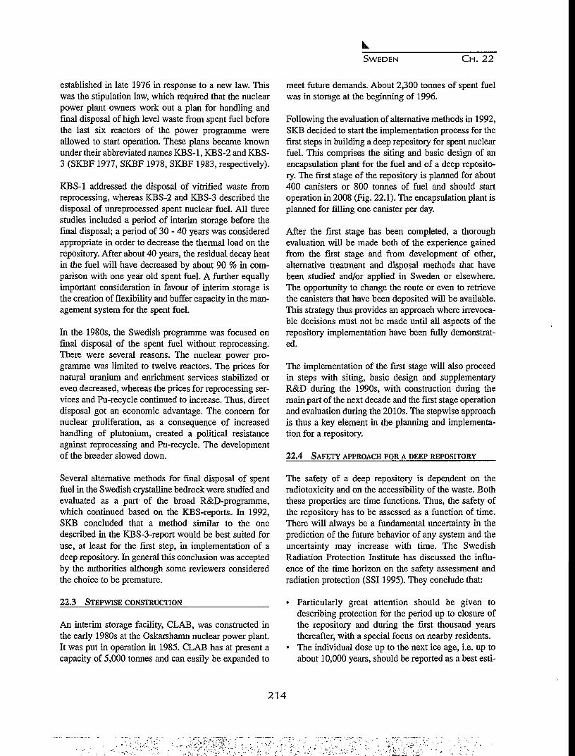
SWEDEN CH. 22
established in late 1976 in response to a new law. Thiswas the stipulation law, which required that the nuclearpower plant owners work out a plan for handling andfinal disposal of high level waste from spent fuel beforethe last six reactors of the power programme wereallowed to start operation. These plans became knownunder their abbreviated names KBS-1, KBS-2 and KBS-3 (SKBF 1977, SKBF 1978, SKBF 1983, respectively).
KBS-1 addressed the disposal of vitrified waste fromreprocessing, whereas KBS-2 and KBS-3 described thedisposal of unreprocessed spent nuclear fuel. All threestudies included a period of interim storage before thefinal disposal; a period of 30 - 40 years was consideredappropriate in order to decrease the thermal load on therepository. After about 40 years, the residual decay heatin the fuel will have decreased by about 90 % in com-parison with one year old spent fuel. A further equallyimportant consideration in favour of interim storage isthe creation of flexibility and buffer capacity in the man-agement system for the spent fuel.
In the 1980s, the Swedish programme was focused onfinal disposal of the spent fuel without reprocessing.There were several reasons. The nuclear power pro-gramme was limited to twelve reactors. The prices fornatural uranium and enrichment services stabilized oreven decreased, whereas the prices for reprocessing ser-vices and Pu-recycle continued to increase. Thus, directdisposal got an economic advantage. The concern fornuclear proliferation, as a consequence of increasedhandling of plutonium, created a political resistanceagainst reprocessing and Pu-recycle. The developmentof the breeder slowed down.
Several alternative methods for final disposal of spentfuel in the Swedish crystalline bedrock were studied andevaluated as a part of the broad R&D-programme,which continued based on the KBS-reports. In 1992,SKB concluded that a method similar to the onedescribed in the KBS-3-report would be best suited foruse, at least for the first step, in implementation of adeep repository. In general this conclusion was acceptedby the authorities although some reviewers consideredthe choice to be premature.
22.3 STEPWISE CONSTRUCTION
An interim storage facility, CLAB, was constructed inthe early 1980s at the Oskarshamn nuclear power plant.It was put in operation in 1985. CLAB has at present acapacity of 5,000 tonnes and can easily be expanded to
meet future demands. About 2,300 tonnes of spent fuelwas in storage at the beginning of 1996.
Following the evaluation of alternative methods in 1992,SKB decided to start the implementation process for thefirst steps in building a deep repository for spent nuclearfuel. This comprises the siting and basic design of anencapsulation plant for the fuel and of a deep reposito-ry. The first stage of the repository is planned for about400 canisters or 800 tonnes of fuel and should startoperation in 2008 (Fig. 22.1). The encapsulation plant isplanned for filling one canister per day.
After the first stage has been completed, a thoroughevaluation will be made both of the experience gainedfrom the first stage and from development of other,alternative treatment and disposal methods that havebeen studied and/or applied in Sweden or elsewhere.The opportunity to change the route or even to retrievethe canisters that have been deposited will be available.This strategy thus provides an approach where irrevoca-ble decisions must not be made until all aspects of therepository implementation have been fully demonstrat-ed.
The implementation of the first stage will also proceedin steps with siting, basic design and supplementaryR&D during the 1990s, with construction during themain part of the next decade and the first stage operationand evaluation during the 2010s. The stepwise approachis thus a key element in the planning and implementa-tion for a repository.
22.4 SAFETY APPROACH FOR A DEEP REPOSITORY
The safety of a deep repository is dependent on theradiotoxicity and on the accessibility of the waste. Boththese properties are time functions. Thus, the safety ofthe repository has to be assessed as a function of time.There will always be a fundamental uncertainty in theprediction of the future behavior of any system and theuncertainty may increase with time. The SwedishRadiation Protection Institute has discussed the influ-ence of the time horizon on the safety assessment andradiation protection (SSI 1995). They conclude that:
• Particularly great attention should be given todescribing protection for the period up to closure ofthe repository and during the first thousand yearsthereafter, with a special focus on nearby residents.
• The individual dose up to the next ice age, i.e. up toabout 10,000 years, should be reported as a best esti-
214

SWEDEN CH. 22
SURFACE FACILITY ;
DEPOSITIONOTHER LONG-LIVEDWASTESTAGE 2
DEPOSITIONSPENT NUCLEAR FUELSTAGE 1
. DEPOSITIONSPENT NUCLEAR FUELSTAGE 2
Figure 22.1. Deep repository showing schematic layout of stage 1 and stage 2.
mate with an estimated margin of error.Environmental protection should be described for thesame period of time.
• For the period from the next ice age onward, qualita-tive assessments should be made of what might hap-pen with the repository, including scenarios takinginto account the risk of increased releases.
The safety of a repository is achieved by the applicationof three principles:
• Level 1 - Isolation. Isolation enables the radionu-clides to decay without coming into contact with manand his environment.
• Level 2 - Retardation and retention. If the isolation isbroken, the quantity of radionuclides that can beleached and reach the biosphere is limited by:- very slow dissolution of the spent fuel;- sorption and very slow transport of radionuclides
in the near field; and- sorption and slow transport of radionuclides in the
bedrock.• Level 3 - Recipient conditions. The transport path-
ways along which any released radionuclides canreach man are controlled to a great extent by the con-ditions where the deep groundwater first reaches thebiosphere (dilution, water use, land use and otherexploitation of natural resources). A favourable
recipient means that the radiation dose to man andthe environment is limited. The recipient and thetransport pathways are, however, influenced by nat-ural changes in the biosphere.
The safety functions at levels 1 and 2 are the mostimportant and the next-most important. They areachieved by means of requirements on the propertiesand performance of both engineered and natural barriersand on the design of the deep repository. Within theframes otherwise defined, a good safety function at level3 is also striven for by a suitable placement and config-uration of the deep repository.
22.5 DEEP REPOSITORY
The isolation of the spent nuclear fuel from the bios-phere is achieved by encapsulating the fuel in a canisterwith good mechanical strength and very longlived resis-tance against corrosion. The conceptual design adoptedis a copper canister with a steel insert. The copper pro-vides a very good corrosion resistance in the geochemi-cal environment foreseen in a deep repository inSweden. The steel insert provides the mechanical pro-tection needed. Each canister contains about 2 tonnes ofspent fuel. The canisters are placed in deposition holesdrilled from the floors of tunnels at about 500 m depthin the crystalline, granitic bedrock (Fig. 22.2). Each can-
215
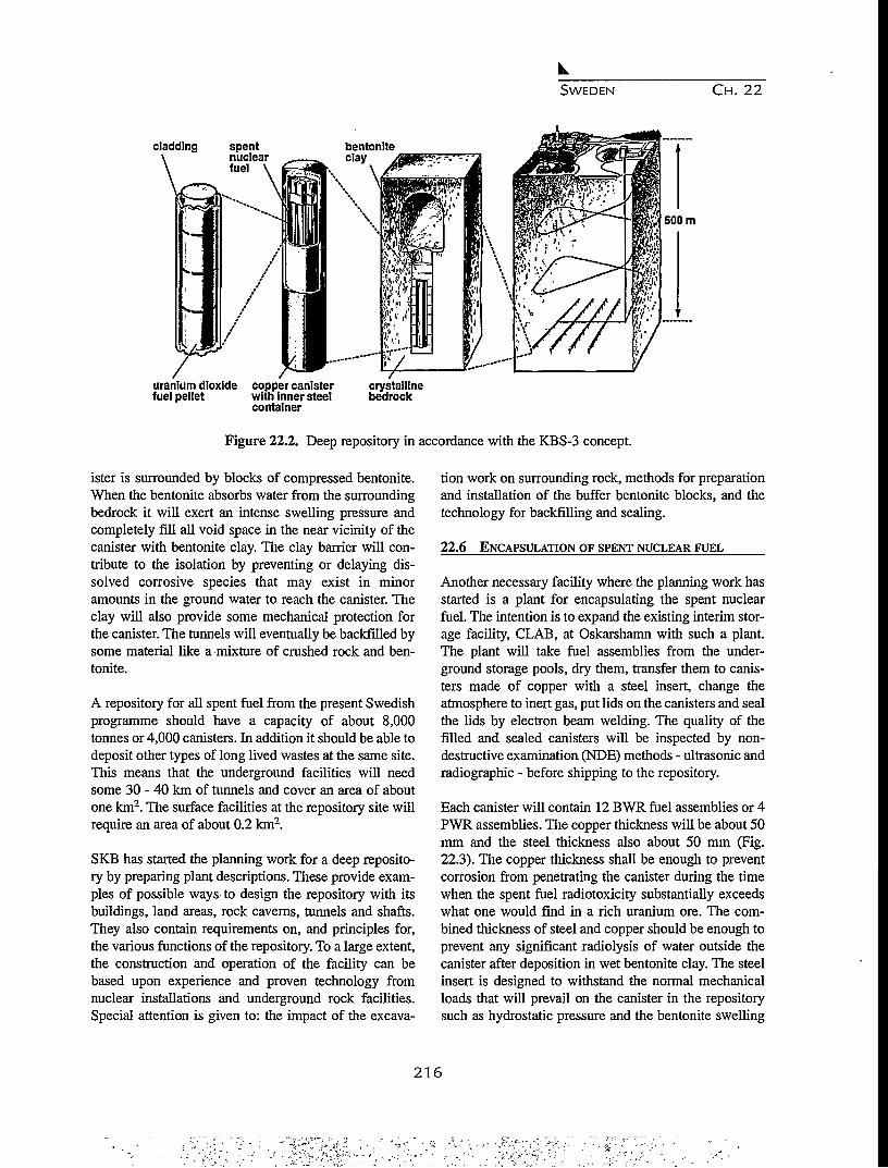
SWEDEN C H . 2 2
cladding
\ .
spentnuclearfuel
500 m
W77uranium dioxide copper canisterfuel pellet with inner steel
container
crystallinebedrock
Figure 22.2. Deep repository in accordance with the KBS-3 concept.
ister is surrounded by blocks of compressed bentonite.When the bentonite absorbs water from the surroundingbedrock it will exert an intense swelling pressure andcompletely fill all void space in the near vicinity of thecanister with bentonite clay. The clay barrier will con-tribute to the isolation by preventing or delaying dis-solved corrosive species that may exist in minoramounts in the ground water to reach the canister. Theclay will also provide some mechanical protection forthe canister. The tunnels will eventually be backfilled bysome material like a mixture of crushed rock and ben-tonite.
A repository for all spent fuel from the present Swedishprogramme should have a capacity of about 8,000tonnes or 4,000 canisters. In addition it should be able todeposit other types of long lived wastes at the same site.This means that the underground facilities will needsome 30 - 40 km of tunnels and cover an area of aboutone km2. The surface facilities at the repository site willrequire an area of about 0.2 km2.
SKB has started the planning work for a deep reposito-ry by preparing plant descriptions. These provide exam-ples of possible ways to design the repository with itsbuildings, land areas, rock caverns, tunnels and shafts.They also contain requirements on, and principles for,the various functions of the repository. To a large extent,the construction and operation of the facility can bebased upon experience and proven technology fromnuclear installations and underground rock facilities.Special attention is given to: the impact of the excava-
tion work on surrounding rock, methods for preparationand installation of the buffer bentonite blocks, and thetechnology for backfilling and sealing.
22.6 ENCAPSULATION OF SPENT NUCLEAR FUEL
Another necessary facility where the planning work hasstarted is a plant for encapsulating the spent nuclearfuel. The intention is to expand the existing interim stor-age facility, CLAB, at Oskarshamn with such a plant.The plant will take fuel assemblies from the under-ground storage pools, dry them, transfer them to canis-ters made of copper with a steel insert, change theatmosphere to inert gas, put lids on the canisters and sealthe lids by electron beam welding. The quality of thefilled and sealed canisters will be inspected by non-destructive examination (NDE) methods - ultrasonic andradiographic - before shipping to the repository.
Each canister will contain 12 BWR fuel assemblies or 4PWR assemblies. The copper thickness will be about 50mm and the steel thickness also about 50 mm (Fig.22.3). The copper thickness shall be enough to preventcorrosion from penetrating the canister during the timewhen the spent fuel radiotoxicity substantially exceedswhat one would find in a rich uranium ore. The com-bined thickness of steel and copper should be enough toprevent any significant radiolysis of water outside thecanister after deposition in wet bentonite clay. The steelinsert is designed to withstand the normal mechanicalloads that will prevail on the canister in the repositorysuch as hydrostatic pressure and the bentonite swelling
216

SWEDEN CH. 22
Figure 22.3. Copper canister with steel insert.
pressure. The total weight of a canister with fuel will beabout 25 tonnes. In total some 4,000 canisters will berequired for the spent fuel arising from the Swedishreactors up to 2010.
The design of the steel insert is still under evaluation.The present reference concept is a cast insert with thicksteel walls between each fuel assembly. This gives agood mechanical stability as well as providing adequateprotection against criticality in the unlikely case that thecanister, at some unspecified future time, should befilled with water.
The fabrication of copper canisters of the size needed isby no means an industrially available technology. Theseal welding technology has recently been demonstratedon a laboratory scale in work sponsored by SKB at TheWelding Institute in UK. Full scale canisters have alsobeen fabricated on the laboratory scale. In order to makekey technology more mature, SKB has decided to createa laboratory for encapsulation technology at the formershipyard in Oskarshamn. This laboratory will be readysometime during 1997 and will primarily be devoted tofurther development of the seal-welding process and theNDE-methods.
The design of the encapsulation plant is in progress. Themain contractors for the design are BNFL for the key
hot cell parts and ABB Atom for the other systems. Thework is at present directed towards final specificationsfor the above mentioned laboratory as well as the devel-opment of an Environmental Impact Statement and aPreliminary Safety Report forming a basis for an appli-cation for a siting and construction permit. The applica-tion is planned for submission in early 1998.
22.7 REPOSITORY SITING
The most crucial part of the development of a deeprepository is the siting process. SKB started geologicalsite investigations at an early stage in the programme.Throughout the 1970s and 1980s, so called study siteswere investigated at some 10 locations scattered fromthe southern to the northern part of the country. Theinvestigations included measurements in boreholes asdeep as 1000 m, as well as geophysical measurementsfrom the surface. The main conclusion from these siteinvestigations was that there are many places in theSwedish bedrock that provide conditions which are suit-able for siting a repository at a depth of about 500 m.This implies that the safety requirements for a site canbe met at many places and that factors other than safetycan also be decisive in siting.
One such factor of importance is the acceptance byauthorities and local residents. After the presentation ofthe RD&D-programme 92, SKB got in contact with sev-eral municipalities in various parts of Sweden. Thesecontacts led to the proposal to start so called feasibilitystudies for the municipality in order to more clearlydefine the possibilities and consequences of siting arepository in the municipality. The intent was that themunicipality as well as SKB should get a comprehen-sive set of documentation on which to base any decisionof further, more detailed studies. A prerequesite was thatthe feasibility study should be based on existing geolog-ical data; no drillings and new measurements would beincluded. The discussions resulted in feasibility studiesin Storuman and Mala in northern Sweden, Lappland(Fig.22.4).
The study for Storuman was published in February of1995, (SKB 1995b) and that for Mala in March 1996(SKB 1996). In both municipalities, two fairly largeareas - 50-100 km2 - were identified to be of interest forfurther investigations as potential host formations for arepository. However, in September of 1995, Storumanhad a referendum on whether to permit further investi-gations for a repository site in the municipality, and theoutcome was more than 70 % no-votes. This means that
217

SWEDEN CH. 22
CLAB + Slmpevarp,
Oskarshamn
Kavlinge'
Figure 22.4. Location of some municipalities inSweden.
SKB's work at Storuman has ceased. The study in Malais now being reviewed by the municipality with the helpof an independent group of experts.
SKB also performed a general study of five municipali-ties: Osthammar, Nykoping, Oskarshamn, Kavlinge andVarberg, where nuclear facilities are already located.The conclusion from this study was that there was aclear interest to continue with specific feasibility studiesfor the three first mentioned municipalities. There wasalso some interest for a study in Varberg, although theexisting geological data for that area are rather meagerand must be supplemented. As a result, feasibility stud-ies are now going on in Osthammar and Nykopingwhereas the proposal is still being evaluated byOskarshamn. Varberg has declined a feasibility study.
SKB has also had fairly extensive discussions with threeother municipalities: Overkalix, Arjeplog and Tranemo.These have finally resulted in negative answers from the
municipalities mainly due to strong local opposition. Ina few other cases, the negative answers were given at anearly stage.
In 1995 SKB published a General Study '95 (SKB1995c) which provides background material and givesan overview of some important siting factors on a scalecovering the whole of Sweden. One main conclusionfrom this study is a confirmation of previous observa-tions that it is not feasible to identify interesting areas onsuch a coarse scale. It is, however, possible to identifysome major areas like Gotland, SkSne and the mountainrange at the border with Norway where the geologicaland other conditions are such that it is of less interest tolook for a site.
Based on the General Study '95, SKB will continue tostudy some parts of Sweden on a regional scale in orderto identify areas of possible interest. The ambition ofSKB is to make feasibility studies of some 5-10 munic-ipalities as a basis for selecting at least two sites forinvestigation including extensive drilling as well as geo-physical, geohydrological and geochemical measure-ments. These investigations will give the necessary database to seek permits to enable detailed site characteriza-tion including construction of tunnels and/or shaftsdown to repository depths. The government has con-cluded that such a detailed investigation means that partof the construction of the future repository facility willactually start. This means that a siting permit accordingto the Act on Management of Natural Resources mustalso be accompanied by a permit according to the Act onNuclear Activities.
Critics of SKB claim that the siting process followed bySKB is non-scientific and unsystematic; some evenclaim that it violates the Swedish environmental protec-tion act. The siting process was, however, outlined indetail in the supplement to RD&D-programme 92,which after a rather extensive review was approved bythe authorities and by the government. The fourth para-graph of the environmental protection act says: For anenvironmentally hazardous activitity, one shall selectsuch a site that the purpose can be achieved at a mini-mum of impact and inconvenience and without unrea-sonable costs. The process followed by SKB for findinga site for the deep repository is fully in line with thisparagraph; the strategy is to find a site where the pur-pose to construct a safe deep repository can be achievedand then at first hand look at sites where there is somelocal interest to consider receiving the facility. Thus, oneshould minimize the inconvenience to areas where there
2 1 8
SWEDEN C H . 22
Figure 22.5. General layout of the Aspo hard rock laboratory.
is no such interest. At the same time, the authoritieswant to have a reasonably broad base for judging thatthere are no other sites which would obviously be betterchoices than the one finally selected for an applicationto construct the repository.
22.8 ASPO HARD ROCK LABORATORY
In order to prepare for the siting and construction of adeep repository, SKB has built the Aspo Hard RockLaboratory. The planning of this facility started some 10years ago in 1986. The work at the laboratory has pro-ceeded in three stages: planning and site investigations,construction, and operations. The first two stages havenow been completed and the operational stage has start-ed. A basic objective in the planning of the laboratorywas to create a facility for research and development in'a realistic and unperturbed environment at a depthplanned for the future repository.
The Aspo HRL is designed to meet the requirements onR&D. The underground construction starts with a tunnelfrom the site of the Oskarshamn nuclear power plantheading north down to about 220 m depth under theisland of Aspo. The tunnel then goes down in a spiralwith a radius of some 150 m down to 450 m depth. The
total length of the tunnel is about 3,600 m. The last 400m were excavated by a Tunnel Boring Machine (TBM)as opposed to the first part that was drilled and blasted.The cross section of the tunnel is about 25 m2 (Fig.22.5).
Overall objectives for the research conducted at Aspoare to:
• increase the scientific understanding of the safetyfeatures and function of a repository;
• develop and test technology that will simplify thedisposal concept and decrease costs while retainingquality and safety; and
• demonstrate the technology that will be used for dis-posal of spent fuel and other long-lived wastes.
When the Aspo-project started in the late 1980s, thework program was formulated in several stages. Thegoal of the first stage was to verify that investigations onthe surface and through boreholes from the surface willprovide enough data on the important properties relatedto safety of the bedrock at the repository level. The com-prehensive site investigation programme, conductedbefore the start of construction, was the basis for pre-dictions on geological, geohydrological and geochemi-
219

SWEDEN CH. 22
cal data and behaviour of the rock at depth. These pre-dictions were then compared with observations andmeasurements performed during the tunnel constructionstage. A general conclusion concerning the first stagegoal is that the methods available for site investigationsare well suited to obtain data and information on thebedrock at a given site. These data can be used to selectthe proper volume of rock needed for a repository and tomake the safety assessment needed for obtaining a per-mit to construct tunnels and/or shafts for startingdetailed site characterization.
The goal of the second stage was to develop the method-ology for such detailed site characterization. During theconstruction of the laboratory, considerable experiencehas been gained in how the detailed studies of the hostrock can be conducted, and a good basis has been laidfor the actual work to be made at a repository site in thefuture.
The other stages were related to improved understand-ing of the natural barrier - the bedrock - and to a demon-stration of the technology to be used in the repository.Some of the tasks addressing these goals have alreadybeen performed, whereas others are part of the ongoingexperimental and investigation programme at AspoHRL. A series of Tracer Retention UnderstandingExperiments (TRUE) is aimed at increasing the knowl-edge on the capacity of the bedrock to retain and retardthe transport of radionuclides in fractured rock.Experimental studies are being carried out to determinehow and at what rate the oxygen, present in the reposi-tory at closure, is consumed by reactions with the rock.A special borehole laboratory - CHEMLAB - has beendeveloped. It permits chemical experiments to be con-ducted under repository-like conditions with respect togroundwater composition and pressure. Such experi-ments will give data to verify models in-situ and checkthe data used to assess the dissolution of radionuclides,the fuel corrosion, the sorption on rock surfaces, the dif-fusion in buffer materials etc. A full-scale (in-active)prototype repository is planned to be built at Aspo. Itwill provide the opportunity to simulate all stages in thedeposition sequence in a realistic environment. It willalso be possible to observe the simulated repository sev-eral years in advance of depositing the first (active) can-ister in the final deep repository.
The work at Aspo has attracted a large internationalinterest, and at present eight foreign organizations fromseven countries are participating in the Aspo pro-gramme. Several of the experiments are conducted with
very active participation by scientists from the foreignparticipants. This provides a good mechanism for fur-ther strengthening the scientific quality of the work andgives all participants access to a broad internationalforum for discussing the planning, execution, evaluationand interpretation of the experiments.
22.9 CONCLUDING REMARKS
The implementation of a deep repository for spentnuclear fuel is a very lengthy and tedious process intoday's society. Considering the time scale intended forthe isolation of spent fuel, it is of course still a short timeperiod. In comparison with many other more commonprojects, however, it is unusual and demanding for allthose involved. It extends over several decades and mustproceed in steps, where each step requires careful plan-ning. This stepwise progress is a key element. It must bestressed that no step should really be irrevocable; itshould always be possible to step back and reconsiderand even take another route.
The siting of a deep repository in Sweden is now inprogress. To complete this process, efforts will be need-ed not only from the responsible implementing organi-zation but from all parties involved such as the safetyauthorities, affected local authorities and political bod-ies. Building of confidence and trust is a key element inthe process. Nuclear power is producing electricity forthe benefit of society, but it is also leaving radioactiveresidues behind. It is our responsibility to handle theseresidues in a safe and proper manner. When the presentnuclear power plants are about to be shut down, thereshould also be facilities in place to take permanent careof the long-lived radioactive residues. This is the respon-sibility of our generation which has benefited from theelectricity produced. It will be up to the following gen-erations to decide on how to use, extend or change thesystem we have provided. In this way we can take careof our responsibility without depriving future genera-tions of their possibilities to take their own actions.Considering the existence of long-lived radioactivewastes, a deep repository for such residues will, howev-er, be an asset for society.
REFERENCESR
Aka 1976, Spent Fuel and Radioactive Waste, Report ofthe Aka Committee, SOU 1976:30 Part I, SOU1976:31 Partn, SOU 1976:41 Appendix, 1976.
SKBF 1977, Handling of Spent Nuclear Fuel and Final
220

SWEDEN C H . 22
Storage of Vitrified High Level Reprocessing Waste,Parts I-V, Projekt Karnbranslesakerhet, Stockholm,November 1976.
SKBF 1978, Handling and Final Storage of Unrepro-cessed Nuclear Fuel, Parts I-H, Projekt Karnbransle-sakerhet, Stockholm, September 1978.
SKBF 1983, Final Storage of Spent Nuclear Fuel -KBS-3, Parts I-IV, Stockholm, May 1983.
SKB 1986, R&D-Programme 86, Parts I-IH, Stockholm,September 1986.
SKB 1989, R&D-Programme 89, Parts I-E, Stockholm,September 1989.
SKB 1992, RD&D-Programme 92, Main report plus 3background reports, Stockholm, September 1992.
SKB 1995a, RD&D-Programme 95, Stockholm,September 1995.
SKB 1995b, Feasibility study for siting of a deep repos-itory within the Storuman municipality, SKBTechnical report 95-08, January 1995.
SKB 1995c, General Siting Study 95, Siting of a deeprepository for spent nuclear fuel, SKB Technicalreport 95-34, October 1995.
SKB 1996, Feasibility study for siting of a deep reposi-tory within the Mala municipality, SKB Technicalreport 96-xx, March 1996, (English version in print).
SSI 1995, Statens Stralskyddsinstitut skyddskriterier foromhandertagande av anvant karnbransle, (SSI pro-tection criteria for handling of spent nuclear fuel),SSI-report 95-02 in Swedish, 1995.
221

222

CHAPTER 23
HIGH LEVEL RADIOACTIVE WASTE MANAGEMENT IN SWITZERLAND:
BACKGROUND AND STATUS 1995
I.C. McKinley and C. McCombie
Nagra (National Cooperative for the Disposal of Radioactive Waste),Hardstrasse 73, 5430 Wettingen, Switzerland
23.1 BACKGROUND
Switzerland is a small country, with limited naturalresources (other than hydro power) and must importabout 80 % of its primary energy needs (predominantlypetroleum products). Electricity covers about 20 % ofenergy demand; about 40 % of the electrical energy issupplied from nuclear plants, with almost all the restbeing generated by hydropower.
Nuclear power production is the main source of Swissradioactive wastes, although wastes arise also in medi-cine, industry and research. Switzerland currently has 5nuclear power plants (pressurized water reactors andboiling water reactors) with a total capacity of 3 GW(e).The spent fuel, containing most of the waste radionu-clides produced by fission, may be prepared for directdisposal or reprocessed to recover useable uranium andplutonium, with the resulting wastes being immobilizedin glass blocks. To date, Swiss disposal planning hasfocused on waste returned from foreign reprocessingplants but, currently, the preferred strategy of the utili-ties is to keep open both options (reprocessing or directdisposal). The prime reason for originally choosing thereprocessing route was to optimize use of resources; thecurrent arguments against reprocessing are primarilyeconomic.
Nuclear power and its future role in the nation's energymix is a controversial issue. The initial widespreadacceptance has been replaced to a significant extent byuncertainty or even opposition; this led hi 1990 to theadoption by popular referendum of legislation placing a10 year moratorium on expansion of nuclear power. Thewaste disposal issue, as will be detailed in the followingsection, plays a prominent part in the debate on nuclearenergy. There is a strong incentive for those responsiblefor waste management to ensure that continuing
progress is made towards development and implementa-tion of an integrated waste management strategy.
23.2 LEGAL, REGULATORY AND ADMINISTRATIVE
ISSUES
The Atomic Law of 1959 clearly placed the responsibil-ity for nuclear waste disposal with the producer of thewaste. The Ruling of 1978 further stipulates that "Thegeneral license for nuclear reactors will be granted onlywhen the permanent, safe management and final dispos-al of radioactive waste is guaranteed'.' This Ruling wasextended by the Government to existing reactor operat-ing licenses and this led to preparation of a specialProject Gewahr (PG85) which, as described below, wassubmitted to the Government for review in 19851.
The safety conditions which the final repositories mustsatisfy are defined in the Guideline R-21 (1980, revised1993) of the Nuclear Regulatory Authorities. Three pro-tection objectives are defined:
• The repositories must ensure the safety of humanbeings and the environment from any harmful effectsof ionizing radiation. Accordingly, the central point isObjective 1, which states: "Radionuclides which canbe released into the biosphere from a sealed reposito-ry as a consequence of realistically assumableprocesses and events may not at any time lead to indi-vidual doses which exceed 10 mrem (0.1 mSv) peryear." This objective is ambitious not only because ofthe absence of any time limit for demonstration ofcompliance but also because of the comparativelylow levels of radiation doses permitted. For compar-ison, the natural radiation exposure of the Swiss pop-ulation results in an average radiation dose of about140 mrem per year, with a range of approximately100 to 300 mrem per year.
223
SWITZERLAND C H . 2 3
• Objective 2 provides a quantitative risk level forjudging the consequences of low-probability scenar-ios: "The individual radiological risk of fatality froma sealed repository subsequent upon unlikelyprocesses and events not taken into consideration inProtection Objective 1 shall, at no time, exceed onein a million per year". The direct radiological risk offatality from a scenario is thus multiplied by the esti-mated probability of the scenario occurring and thisproduct should not exceed one in a million per yearwhen summed over all such scenarios. For compari-son, the dose limit of 0.1 mSv per year correspondsto a nominal risk of fatality of 5 in a million per year.
• Besides the safety aspects, the Guideline R-21reflects the understanding that the responsibility fordisposing of radioactive waste lies with today's ben-eficiaries of nuclear power and should not be passedon to future generations. This is expressed inObjective 3: "A repository must be designed in sucha way that it can at any time be sealed within a fewyears. After a repository has been sealed, it must bepossible to dispense with safety and surveillancemeasures." Once the repository has been sealed, itmust thus be possible to "forget" the radioactivewaste in the sense that it should not be necessary forfuture generations to concern themselves with it.There is thus no requirement for monitoring orretrievability of the waste.
In addition to the requirements formulated in these threeprotection objectives, non-nuclear regulations must alsobe taken into consideration; these include internationallaw, district planning, environmental protection; andnature conservation.
As noted above, the producers of nuclear waste areresponsible for waste management (for all waste cate-gories). Hence the electricity supply utilities involved innuclear power generation and the Swiss Confederation(which is directly responsible for the waste from medi-cine, industry and research) joined together in 1972 toform the "National Cooperative for the Disposal ofRadioactive Waste" (Nagra). Nagra is responsible forthe disposal and, if required, pre-emplacement condi-tioning of wastes. The responsibility for spent fuelreprocessing and transport, for the waste conditioning atpower plants and for interim storage remains directlywith the utilities. In 1994, a separate organization wasfounded to actually construct and operate a L/ILWrepository at a site selected by Nagra, theGenossenschaft fur die Nukleare Entsorgung
Wellenberg (GNW).
23.3 CHARACTERISTICS AND EVOLUTION OF THE
SWISS NUCLEAR WASTE DISPOSAL PROGRAMME
Since the founding of Nagra in 1972, work has been car-ried out on the development of disposal concepts andidentification of potential sites for such facilities.Working on the principle of the multi-barrier concept,the requirements for packaging, engineered structuresand geological isolation were derived for different typesof waste. Two separate geological repositories areplanned2; one for low-level radioactive wastes andshorter-lived intermediate-level wastes (L/ELW) andanother for high-level wastes (HLW) and intermediate-level wastes containing higher concentrations of long-lived alpha- emitters ("TRU").
Highest priority at present is allocated to the L/ILWrepository which is intended to be implemented in hori-zontally accessed rock caverns with some hundreds ofmetres of overburden. An extensive site-selection proce-dure resulted in 1993 in the nomination of Wellenberg inCentral Switzerland as the preferred repository location.More detailed site-characterization work, to form thebasis of the application for construction and operationpermits, is now ongoing. The principal for the develop-ment of Wellenberg as a repository site has been accept-ed in public Referenda at the community level. It is alsosupported by the federal authorities. At the cantonallevel, however, there has been opoposition, leading in1995 to a popular vote which produced a narrow major-ity against the currently proposed project. Nevertheless,current planning assumes that, following appropriateamendments to the project, the L/ELW repository shouldbe operational early next century.
For the present limited nuclear programme inSwitzerland, operation of all plants for a 40 year life-time will result in around 3000 t of spent fuel. If all ofthis were reprocessed abroad, the resulting volume ofvitrified waste returned would only be around 500 m3,although several thousand cubic metres of additionalL/ELW could also be returned (depending on the con-tract with the reprocessor). It is planned to store HLWfor at least 40 years in order to reduce the thermal load-ing of the repository, so that ample time is available forproject development. A centralized facility for dry caskstorage of spent fuel and of vitrified HLW and for otherreprocessing wastes will be constructed before the turnof the century by the ZWTLAG organization, a daughtercompany of the utilities.
224

SWITZERLAND CH. 23
Implementation of a HLW repository will not take placein Switzerland before the year 2020, and there are soundeconomic arguments for delaying this date even further.Nevertheless, there is strong pressure from the publicand the government - and a strong will on the part of thewaste producers - to move the project ahead as quicklyas possible, at least up to the level of demonstrating thefeasibility of construction of a safe repository at a poten-tial site.
Site selection is very much constrained by the small sizeof Switzerland and by its relatively active tectonic set-ting. The current geological consensus is that the oroge-ny which built the Swiss Alps is still continuing andthere is still net uplift in this area of ~l-2 mm/year(which is equivalent to 1-2 km in the million yeartimescale which is considered for HLW safety analy-sis!). Excluding alpine areas and other complex geolog-ical structures associated with the Jura mountains andthe Rhine Graben leaves only a limited area in NorthernSwitzerland which would be potentially suitable. Withinthis area, two host rock options are considered - eitherthe crystalline basement or one of the overlying, lowpermeability sediment layers.
The current conceptual repository design was developedtaking into account the potential host rocks, the very lowvolumes of HLW expected and the government require-ment for an early, convincing demonstration of safety ofwaste disposal as a condition of extending reactor oper-ating licenses. These factors together led to designswhich are certainly robust (or even overdesigned) andare not optimized in an economic sense. Accordingly,although estimates of absolute costs for the small sizerepository required are comparable to those from othercountries, the costs per unit waste volume (or per kWhof nuclear electricity) are relatively high. Optimizationof designs would, therefore, clearly be an importantobjective before moving to an implementation phase.The concept, illustrated in Figure 23.1 for the crystallinehost rock option3, has the following features:
1. extremely deep disposal (about 1 km below surface)in a carefully-constructed facility;
2. in-tunnel emplacement of HLW waste packages in ageologic medium whose principal roles are to limitwater flows and to ensure favorable groundwaterchemistry;
3. very massive engineered barriers; in addition to thevitrified waste in its steel fabrication canister, a 25cm thick steel overpack is envisaged which is sur-rounded by more than one metre of highly compact-
Figure 23.1. Sketch of possible repository layout. Thecase of 3 HLW emplacement panels ona single level and TRU silos in separateblocks of low-permeability basementbetween major (layout-determining)water-conducting faults.
ed bentonite clay (Fig. 23.2); and4. co-disposal of TRU in silos or in caverns in a sepa-
rate part of the repository.
Analysis of this concept in the Project Gewahr 1985study (mentioned above), showed that, for all realisticscenarios analyzed, the performance guideline was metwith large margins of safety. In their review of this pro-ject, the government concluded that this concept wouldprovide sufficient safety in a crystalline basement hav-ing the properties postulated by Nagra. However, onlylimited data from isolated boreholes were available in1985, and the Government authorities requested moreevidence that suitable rock formations of an appropriateextent could be identified in Switzerland. The govern-ment review also strongly recommended that the option
225

SWITZERLAND C H . 23
Figure 23.2. Waste emplacement geometry (dimensions in metres).
of disposal in sedimentary formations be considered inmore depth. Despite these caveats, the waste disposalissue was no longer tied directly to operation of existingpower plants, although it is understood that more evi-dence of siting feasibility would be required before anyapplications for new reactor licenses could be sought.
Since 1985, the regional investigation of the crystallinebasement has been completed and documented4. Thegeological studies have clearly shown that the extent ofthe accessible crystalline basement is much less thanoriginally thought due to the presence of a previouslyunknown, extensive Permocarboniferous trough whichcuts the region. Only two restricted areas remain forselection of a possible site, each covering about 50 km2.Nevertheless, it does seem feasible to find a suitablerepository for the required low volume of waste and astrategy for site characterization has been developed. Inparallel, investigations of the sedimentary options haveproceeded from a desk study to select potential host for-mations through to identification of specific potentialsiting areas. The two sedimentary host rocks investigat-ed in detail were Opalinus Clay, which exists in a later-ally extensive but rather thin layer in NorthernSwitzerland, and Lower Freshwater Molasse, where the
formations are large but somewhat heterogeneous5. ForOpalinus Clay, which was identified as the higher prior-ity option for Nagra, a total potential siting area of some100 km2 has been identified. Programmes of site-specif-ic studies are now running in parallel in the crystallinebasement and the Opalinus Clay.
The next major milestone in the HLW programme willbe the demonstration of repository siting feasibility(Project Entsorgungsnachweis) scheduled for 2000.This may include one or both of the potential sitingareas studied.
23.4 ONGOING GEOLOGICAL STUDIES ASSOCIATED
WITH THE HLW PROGRAMME
Geological characterization prior to repository construc-tion is planned to progress in three phases. Phase I is aregional study of potential host rocks from the surface,involving seismic studies, investigation from deep bore-holes, etc. This phase is followed by more detailedinvestigations of a potential siting area from the surface(Phase H), and then Phase HI underground studiesinvolving construction of an access shaft to the potentialrepository depth and an underground laboratory.
226
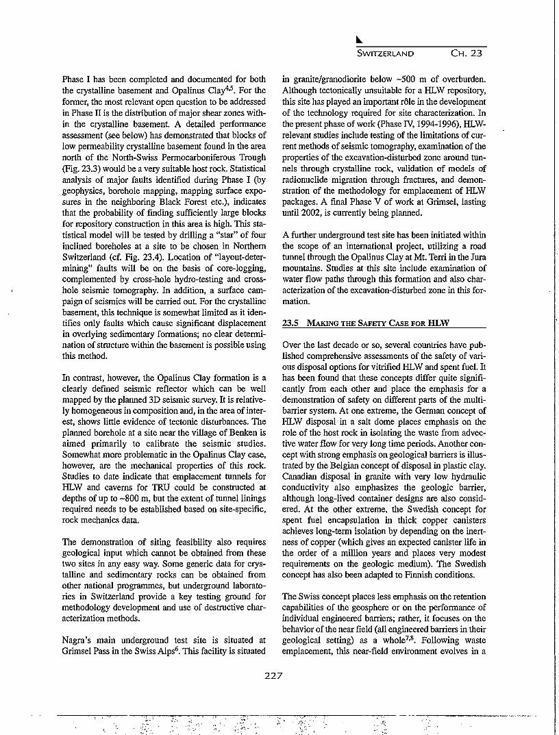
SWITZERLAND C H . 2 3
Phase I has been completed and documented for boththe crystalline basement and Opalinus Clay4'5. For theformer, the most relevant open question to be addressedin Phase II is the distribution of major shear zones with-in the crystalline basement. A detailed performanceassessment (see below) has demonstrated that blocks oflow permeability crystalline basement found in the areanorth of the North-Swiss Permocarboniferous Trough(Fig. 23.3) would be a very suitable host rock. Statisticalanalysis of major faults identified during Phase I (bygeophysics, borehole mapping, mapping surface expo-sures in the neighboring Black Forest etc.), indicatesthat the probability of finding sufficiently large blocksfor repository construction in this area is high. This sta-tistical model will be tested by drilling a "star" of fourinclined boreholes at a site to be chosen in NorthernSwitzerland (cf. Fig. 23.4). Location of "layout-deter-mining" faults will be on the basis of core-logging,complemented by cross-hole hydro-testing and cross-hole seismic tomography. In addition, a surface cam-paign of seismics will be carried out. For the crystallinebasement, this technique is somewhat limited as it iden-tifies only faults which cause significant displacementin overlying sedimentary formations; no clear determi-nation of structure within the basement is possible usingthis method.
In contrast, however, the Opalinus Clay formation is aclearly defined seismic reflector which can be wellmapped by the planned 3D seismic survey. It is relative-ly homogeneous in composition and, in the area of inter-est, shows little evidence of tectonic disturbances. Theplanned borehole at a site near the village of Benken isaimed primarily to calibrate the seismic studies.Somewhat more problematic in the Opalinus Clay case,however, are the mechanical properties of this rock.Studies to date indicate that emplacement tunnels forHLW and caverns for TRU could be constructed atdepths of up to ~800 m, but the extent of tunnel liningsrequired needs to be established based on site-specific,rock mechanics data.
The demonstration of siting feasibility also requiresgeological input which cannot be obtained from thesetwo sites in any easy way. Some generic data for crys-talline and sedimentary rocks can be obtained fromother national programmes, but underground laborato-ries in Switzerland provide a key testing ground formethodology development and use of destructive char-acterization methods.
Nagra's main underground test site is situated atGrimsel Pass in the Swiss Alps6. This facility is situated
in granite/granodiorite below ~500 m of overburden.Although tectonically unsuitable for a HLW repository,this site has played an important role in the developmentof the technology required for site characterization. Inthe present phase of work (Phase IV, 1994-1996), HLW-relevant studies include testing of the limitations of cur-rent methods of seismic tomography, examination of theproperties of the excavation-disturbed zone around tun-nels through crystalline rock, validation of models ofradionuclide migration through fractures, and demon-stration of the methodology for emplacement of HLWpackages. A final Phase V of work at Grimsel, lastinguntil 2002, is currently being planned.
A further underground test site has been initiated withinthe scope of an international project, utilizing a roadtunnel through the Opalinus Clay at Mt. Terri in the Juramountains. Studies at this site include examination ofwater flow paths through this formation and also char-acterization of the excavation-disturbed zone in this for-mation.
23.5 MAKING THE SAFETY CASE FOR HLW
Over the last decade or so, several countries have pub-lished comprehensive assessments of the safety of vari-ous disposal options for vitrified HLW and spent fuel. Ithas been found that these concepts differ quite signifi-cantly from each other and place the emphasis for ademonstration of safety on different parts of the multi-barrier system. At one extreme, the German concept ofHLW disposal in a salt dome places emphasis on therole of the host rock in isolating the waste from advec-tive water flow for very long time periods. Another con-cept with strong emphasis on geological barriers is illus-trated by the Belgian concept of disposal in plastic clay.Canadian disposal in granite with very low hydraulicconductivity also emphasizes the geologic barrier,although long-lived container designs are also consid-ered. At the other extreme, the Swedish concept forspent fuel encapsulation in thick copper canistersachieves long-term isolation by depending on the inert-ness of copper (which gives an expected canister life inthe order of a million years and places very modestrequirements on the geologic medium). The Swedishconcept has also been adapted to Finnish conditions.
The Swiss concept places less emphasis on the retentioncapabilities of the geosphere or on the performance ofindividual engineered barriers; rather, it focuses on thebehavior of the near field (all engineered barriers in then-geological setting) as a whole7-8. Following wasteemplacement, this near-field environment evolves in a
227

SWITZERLAND CH. 23
Low-permeability domain of crystalline basementHigher-permeability domain of crystalline basementMajor water-conducting faults \ ,Mesozoic sedimentary cover \Permo-Carboniferous TroughRhine river / Quaternary gravel
Water-conducting features(transmissive elements):a) cataclastic zones§) jointed zones with open joints(5) fractured dykes
Figure 23.3. Diagrammatic representation of the conceptual model of the crystalline basement.
well defined manner.
After emplacement, water will resaturate the surround-ing rock and then invade the bentonite which will swellto seal any gaps. Temperatures in the bentonite willincrease due to heat from the canister, but storage ofwaste prior to emplacement ensures that the maximumtemperature in the backfill does not exceed ~160°C.Calculations indicate that complete resaturation maytake in the order of hundreds of years. The steel canistercorrodes anaerobically at a very low rate (~50 m/year).Only after ~1000 years will mechanical failure occurdue to pressure from the expanding bentonite. The water
chemistry in the compacted bentonite will be deter-mined by interactions of inflowing granitic groundwaterwith mineral surfaces in this microporous material. Thebulk of the bentonite itself will, not undergo any signifi-cant mineralogical alteration over relevant timescales(~1 million years).
After canister failure, corrosion of the glass will occur inan environment with effectively stagnant porewater.Corrosion of the glass is expected to gradually releasethe contained radionuclides over a period of the order of105 years. The release of many radionuclides may, how-ever, be further constrained by their very low solubili-
228

SWITZERLAND C H . 23
•
EXPLANATION
Step of Investigation Programme
Sedimentary Cover
Higher-Permeability Domainof Crystalline Basement
Low-Permeability Domainof Crystalline Basement
Major Water-Conducting Fault
Four Inclined Boreholes(Star Configuration)
Reflection Seismics Survey
0 0 Vertical Borehole
ca.1km
Seismic TomographyCrosshole Hydrotesting
m m Proposed Disposal Area
Boreholes at Shaft Location (S)
iiiiiiiiiini Proposed Disposal Area
0
Figure 23.4. Illustration of the investigation concept for the crystalline basement.
ties. Even after radionuclides are released from the glassmatrix, output to the geosphere is greatly limited by thetransport resistance of the bentonite backfill. Due to itsextremely low hydraulic conductivity, solute transportthrough the saturated bentonite will occur predominant-ly by diffusion. Sorption processes result in very lowdiffusivities for many radionuclides, so that their trans-port time through the backfill exceeds their half-lives,and thus, output is negligible. This analysis of the repos-itory near field is believed to be robust7, in that it doesnot take credit for all possible processes which woulddecrease release rates, and is relatively insensitive to thevariation of uncertain parameters within reasonableranges.
Although sufficient safety can be demonstrated withonly minimal requirements on the geology, the geologi-cal barrier can also be extremely powerful, reducing the
already low concentrations of radionuclides yet further.Under the expected geological conditions in NorthernSwitzerland, the geological barrier would ensure that, ineffect, no releases to the human environment wouldoccur for all timescales which are meaningful (up to onemillion years). The calculation of retardation of radionu-clides in the geosphere is, however, more sensitive toparameter values which are difficult to determine in thefield and hence a safety case based strongly on the bar-rier effect of a fractured geologic medium is less robust.
The demonstration of long-term safety for a HLWrepository must be based upon predictive modeling, andit is important to realize the capabilities and the limita-tions of such models. The mathematical models used inperformance assessment are supported by a range oflaboratory and field experimental studies, but the extrap-olation of such work to very long timescales must also
2 2 9

SWITZERLAND CH. 23
be justified. Enhanced confidence in our understandingof long-term performance of the near-field, in particular,may be illustrated by using natural analogues.
A natural analogue is a process that has occurred in thepast and is similar to those that are predicted to occur inthe future evolution of a repository. The proposed corro-sion rates of the waste matrix and canister in the expect-ed chemically reducing environment can be supportedby observation of the preservation of archaeologicalglass and steel artifacts over millennia. Mineralogicalstability of bentonite can be shown on an even longertimescale by observations of natural bentonites that haveremained unaltered for millions of years in conditionscomparable to those expected in the repository. Even theability of clay to isolate radioactive substances can beillustrated by natural ore bodies in appropriate geologicsettings.
A safety case made on the robustness of a system ofengineered barriers appears to be appropriate to theSwiss geological environment, and it is interesting tonote that a very similar concept has been adopted byJapan (a country with even more complex and tectoni-cally active geology than Switzerland) in their H-3 per-formance assessment.
23.6 THE SWISS PROGRAMME IN AN INTERNATIONAL
CONTEXT
The Swiss waste management programme, although rel-atively small in terms of budget and manpower, is verywide in scope, with one site currently being character-ized in detail for a L/TLW repository and two types ofhost rocks under investigation for disposal of vitrifiedHLW and long-lived ILW. This programme is only fea-sible if priorities are set and adhered to, and if maximumadvantage is taken of work performed elsewhere.Therefore, extensive use is made of international collab-oration agreements in order to spread the work load.Individual information exchange agreements with otherprogrammes have allowed effort to focus in specificareas. For example, Switzerland could deliberately con-centrate on studies of steel canisters for HLW becauseSweden has concentrated on copper, and a bilateralNagra/SKB agreement provided for exchange of results.Such agreements also allowed direct cooperation/co-funding of larger studies, such as the Japan/Sweden/Switzerland (JSS) study of the leaching of vitrifiedHLW. Cooperation with the US DOE has allowedresults from the Swiss underground test site to be madeavailable to modeling groups in the US who, in turn,
make their interpretations available to Nagra.
Apart from active participation in the IAEA and theNEA, Nagra has formal agreements with the EuropeanEconomic Community (EEC), United States (DOE,NRC), Sweden (SKB), Finland (Posiva), France (CEAand ANDRA), Belgium (ONDRAF, CEN/SCK),Germany (GSF/BRG), Japan (PNC), Spain (ENRESA),Taiwan (AEC) and the United Kingdom (NIREX).Informal collaborations extend the list further.
23.7 CONCLUSION
Despite its small size and limited nuclear power capaci-ty, Switzerland has succeeded in establishing an interna-tionally recognized programme for management ofradioactive wastes. The restricted size makes lines ofcommunication shorter and coordination of effort sim-pler. The relatively strong economy makes the financingof projects, without the benefits of scale, a feasibleproposition, although the economic sense of establish-ing various small-scale projects through the world canbe questioned. Sound technical projects can be devel-oped and implemented with limited human resources,provided that care is taken to make polyvalent use ofexpertise and to profit from mutually beneficial collabo-ration with other national programs. Even front-line sci-ence and advanced engineering skills are, however, oflittle use if public opposition prevents their application.Hence, it is important that a waste management organi-zation like Nagra devotes strong efforts to communica-tion with the public at all levels.
REFERENCES
1. Nagra, "Projekt Gewahr 1985: Nuclear waste man-agement in Switzerland: Feasibility studies and safe-ty analysis"; Nagra Project Gewahr Report series,NGB 85-09, Nagra, Baden, Switzerland, 1985.
2. Nagra, Nukleare Entsorgung Schweiz - Konzept undRealisierungsplan; Nagra Technical Report series,NTB 92-02, Nagra, Wettingen, Switzerland, 1992.
3. Nagra, Kristallin-I: Conclusions from the regionalinvestigation programme for siting a HLW reposito-ry in the crystalline basement of NorthernSwitzerland; Nagra Technical Report series, NTB93-09E, Nagra Wettingen, Switzerland, 1994.
4. Thury, M., et.al., Geology and hydrogeology of the
230

SWITZERLAND C H . 2 3
crystalline basement of Northern Switzerland -Synthesis of regional investigations 1981-1993 with-in the Nagra radioactive waste disposal programme;Nagra Technical Report series, NTB 93-01, NagraWettingen, Switzerland, 1994.
5. Nagra, Sedimentstudie - Zwischenbericht 1993:Zusammenfassende Uebersicht der Arbeiten von1990 bis 1994 und Konzept fur weitereUntersuchungen; Nagra Technical Report series,NTB 94-10, Nagra Wettingen, Switzerland, 1994.
6. Nagra, Grimsel Test Site - Overview and TestPrograms; Nagra Technical Report series, NTB 85-46, Nagra Wettingen, Switzerland, 1985.
7. Nagra, Kristallin-I - Performance assessment; NagraTechnical Report series, NTB 93-22, Nagra, Wettin-gen, Switzerland, 1995.
8. Neall, F.B., (ed), Kristallin-I - Results in perspective;Nagra Technical Report series, NTB 93-23, NagraWettingen, Switzerland (1996).
231

232

CHAPTER 24
Low LEVEL RADIOACTIVE WASTE MANAGEMENT IN TAIWAN
C M. Tsai and D. S. Liu
Nuclear Energy Society, Taipei, Taiwan
24.1 BACKGROUND
The commercial operation of Chinshan Nuclear PowerPlant (NPP) Unit one marked the beginning of Taiwan'snuclear power program. There are now three NPPs eachconsisting of two units, in operation. With a generatingcapacity of 5,144 MWe, nuclear power produces some30 percent of the electricity supplies in Taiwan.However, the nuclear power component is decreasing asthe power demand increases. In order to meet theincreased power demand, the Taiwan Power Company(TPC), a state-run and sole electricity utility in Taiwan,decided to build one more nuclear power plant with tworeactors at the Yenliao Site in addition to the othersources. Detailed information about Taiwan's nuclearpower program is shown in Table 24.1.
As far as low level radwaste (LLRW) is concerned, TPCis the principal source contributing more than 90 percentof total volume of waste produced in Taiwan. Small pro-ducers in the medical and research institutes and univer-sities are responsible for the remaining 10 percent.
24.2 RADWASTE MANAGEMENT POLICY AND
ORGANIZATIONAL SCHEME
24.2.1 Policy
On the 16th of September 1988, the Executive Yuan(the Cabinet) promulgated the Radwaste ManagementPolicy (RWMP) that set up the principal guidelines toenable the Taiwan nuclear industry to plan and manageits radwaste. Highlights of the RWMP concerningLLRW are summarized as follows:
• the radwaste producers should strive to minimize thewaste generation rate and reduce the volume;
• the responsibility of safely treating, transporting,storing, and disposing of radwaste should rest withthe producer. Therefore, the producer is responsiblefor the necessary expenses; and
• an LLRW disposal site should be located by 1996,and operational by 2002.
24.2.2 Organizational Scheme
The organizations related to radwaste management areshown in Figure 24.1. Both the Atomic Energy Council(AEC) and the Ministry of Economic Affairs (MOEA)are under the Executive Yuan. The Fuel Cycle andMaterials Administration (FCMA), a subordinate orga-
Table 24.1. Information on nuclear power plants in Taiwan.
Unit Reactor Type InstalledCapacity
CommercialOperation
Status
Chinshan 1 (Cl)Chinshan 2 (C2Kuosheng 1 (Kl)Kuosheng 2 (K2)Maanshan 1 (Ml)Maanshan 2 (M2)Yenliao
BWR/4BWR/4BWR/6BWR/6PWRPWR
ABWR
6366369859859519511300
1978197919811982198419852000
(scheduled)
operatingoperatingoperatingoperatingoperatingoperatingbidding
233

TAIWAN CH. 24
nization to the AEC, assumes-regulatory control overradwaste management matters. The Institute of NuclearEnergy Research (INER) was empowered by AEC totake responsibility for collecting radwaste generated bysmall producers and treat the waste as necessary. InTPC, the Nuclear Backend Management Department(NMBD) and the Nuclear Operation Department (NOD)take care of radwaste generated by the NPPs. NOD'smajor responsibility is to supervise treatment and stor-age of LLRW within the NPPs, whereas NMBD isresponsible for radwaste transportation, the operationsof both the Lan-yu storage site and the VolumeReduction Center, but more importantly, the final dis-posal of LLRW in Taiwan.
24.3 TECHNICAL ASPECTS OF LLRW MANAGEMENT
Before introducing the detailed technical issues ofLLRW management in Taiwan, it is better to review theLLRW management diagram (see Fig. 24.2).
24.3.1 Radwaste Generation
LLRW in Taiwan can be divided into two categories:wet waste and dry active waste. Wet wastes, namely:evaporation residues, filter sludges, and spent beadresins, are first solidified in carbon-steel drums and thenstored in structurally safe warehouses. Dry activewastes, which are mainly waste paper, clothes, plastics,wood materials, metal, etc., are either segmented or
shredded and also stored in warehouses. The cumulativeamounts of radwaste generated through August 1994 arelisted in Table 24.2. Cement is the most commonly usedsolidification agent for wet waste. However, bitumen isused in solidifying incinerator ash.
Thanks to waste reduction efforts implemented byindustry, the annual radwaste generation rate at the threenuclear power plants has been decreased from more than12,000 drums prior to 1990 to less than 8,000 drumsafterwards. A particularly significant reduction has beenachieved for solidified wastes. Together with radwastegenerated by small producers, the present annual rad-waste generation rate is approximately between 5500and 6500 drums. Up to now, almost half of the radwastedrums have been shipped to the Lan-Yu NationalStorage Site for extended storage. However, the remain-der of the radwaste is stored in warehouses on site. Asthe nuclear facilities are nearly running out of storagecapacity, a computerized and improved and betterequipped on-site warehouse at two of the three NPPsand at INER is either being constructed or is planned.These new facilities are scheduled to commence opera-tion in the near future.
24.3.2 Waste Volume Reduction
Reducing the volume of both combustible and com-pactable wastes is justified as a good way of mitigatingstorage pressures given the ever-increasing quantities of
EXECUTIVE YUAN
1AEC MOEA
INER FCMA TPC
NBMD NOD
VCR Lan-Yu I ShipI 1 I ' '
SMALL PRODUCERS
NPP1 NPP2 , NPPTj
Disposal Site
Figure 24.1. Organizations related to radwaste management in Taiwan.
234

TAIWAN CH. 24
Table 24.2. Total amount of LLRW in Taiwan (unit: 55 gal. drams).
Plant
NPPI (C1&C2)NPP 2 (K1&K2)NPP 3 (M1&M2)INERTotal
Solidified Waste
43,68453,0907,004
13,774117,552
Non-Solidified Waste
31,47420,8763,627
328
56,305
Totals
75,15873,96610,63114,102
173,857
LLRW. Hence, TPC built a Volume Reduction Center atKuosheng NPP site. The center comprises a controlledair incinerator and a supercompactor. With a capacityfor burning 100 kg/hr of combustible waste and com-pressing five waste drams per hour of compactablewaste, this center is able to eliminate about 3,500 wastedrums annually. This has helped to relieve storage prob-lems to a great extent. The important operating parame-ters of the Volume Reduction Center are shown in Table24.3. INER has also constructed a controlled-air type ofincinerator with a burning rate of 40 kg/hr to treat com-bustible wastes originating from small producers island-wide.
age capacity of 98,000 drums with three drums beingstacked vertically. As of August 1996, the site hadreceived about 97,700 waste drams, and it is anticipatedto be full by 1996. However, in a continual search forsufficient storage space and to allow ample time for pro-ceeding with the LLRW disposal program, TPC, the siteowner, plans to expand the storage capability by addingsix better shielded trenches with a capacity of 59,000drams. Simultaneously, an optimized waste drum load-ing pattern will be adopted, making better use of theland. The environmental impact report for this project isunder review by the AEC's Environment EvaluationCommittee.
24.3.3 Lan-Yu Interim Storage
The National Lan-Yu Storage Site provides off-siteinterim storage for solidified radwaste. This site is locat-ed on the small island of Lan-Yu that has an area ofabout 45 km2, and indeed, was originally designed as aport of departure for sea dumping that is no longerallowed. Twenty-three semi-underground engineeringtrenches were constructed on the site, providing a stor-
24.3.4 LLRW Transportation
Due to the need to continually ship solidified LLRW tothe Lan-Yu site before the disposal facility was commis-sioned, TPC built a modern LLRW transport ship, Teen-Kung No. 1, to replace an old ship in 1991. The newship is 53 meters long and has a deadweight of 737 met-ric tons at the designed draft. It can reach a speed of 11.5knots. Furthermore, it features a double-shell hull, auto-
NPP-1
NPP-2
NPP-3
Medical
Industries
Research
Dry Waste VR CENTER
Wet Waste L-| SOLIDIFICATION SYSTEM
INER
Figure 24.2. Diagram of low level radwaste management in Taiwan.
235
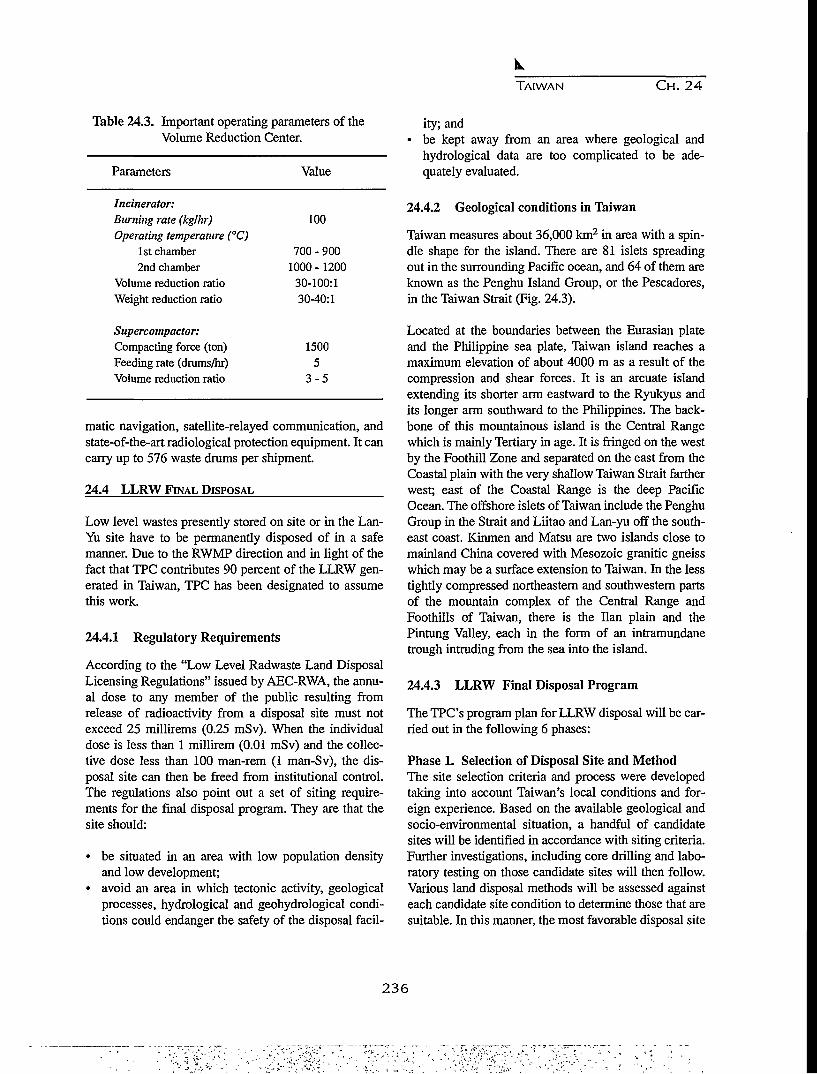
TAIWAN CH. 24
Table 24.3. Important operating parameters of theVolume Reduction Center.
Parameters
Incinerator:Burning rate (kg/hr)Operating temperature (°C)
1st chamber2nd chamber
Volume reduction ratioWeight reduction ratio
Supercompactor:Compacting force (ton)Feeding rate (drums/hr)Volume reduction ratio
Value
100
700 - 9001000 - 1200
30-100:130-40:1
15005
3-5
matic navigation, satellite-relayed communication, andstate-of-the-art radiological protection equipment. It cancarry up to 576 waste drums per shipment.
24.4 LLRW FINAL DISPOSAL
Low level wastes presently stored on site or in the Lan-Yu site have to be permanently disposed of in a safemanner. Due to the RWMP direction and in light of thefact that TPC contributes 90 percent of the LLRW gen-erated in Taiwan, TPC has been designated to assumethis work.
24.4.1 Regulatory Requirements
According to the "Low Level Radwaste Land DisposalLicensing Regulations" issued by AEC-RWA, the annu-al dose to any member of the public resulting fromrelease of radioactivity from a disposal site must notexceed 25 millirems (0.25 mSv). When the individualdose is less than 1 millirem (0.01 mSv) and the collec-tive dose less than 100 man-rem (1 man-Sv), the dis-posal site can then be freed from institutional control.The regulations also point out a set of siting require-ments for the final disposal program. They are that thesite should:
• be situated in an area with low population densityand low development;
• avoid an area in which tectonic activity, geologicalprocesses, hydrological and geohydrological condi-tions could endanger the safety of the disposal facil-
ity; and• be kept away from an area where geological and
hydrological data are too complicated to be ade-quately evaluated.
24.4.2 Geological conditions in Taiwan
Taiwan measures about 36,000 km2 in area with a spin-dle shape for the island. There are 81 islets spreadingout in the surrounding Pacific ocean, and 64 of them areknown as the Penghu Island Group, or the Pescadores,in the Taiwan Strait (Fig. 24.3).
Located at the boundaries between the Eurasian plateand the Philippine sea plate, Taiwan island reaches amaximum elevation of about 4000 m as a result of thecompression and shear forces. It is an arcuate islandextending its shorter arm eastward to the Ryukyus andits longer arm southward to the Philippines. The back-bone of this mountainous island is the Central Rangewhich is mainly Tertiary in age. It is fringed on the westby the Foothill Zone and separated on the east from theCoastal plain with the very shallow Taiwan Strait fartherwest; east of the Coastal Range is the deep PacificOcean. The offshore islets of Taiwan include the PenghuGroup in the Strait and Liitao and Lan-yu off the south-east coast. Kinmen and Matsu are two islands close tomainland China covered with Mesozoic granitic gneisswhich may be a surface extension to Taiwan. In the lesstightly compressed northeastern and southwestern partsof the mountain complex of the Central Range andFoothills of Taiwan, there is the Han plain and thePinning Valley, each in the form of an intramundanetrough intruding from the sea into the island.
24.4.3 LLRW Final Disposal Program
The TPC's program plan for LLRW disposal will be car-ried out in the following 6 phases:
Phase 1. Selection of Disposal Site and MethodThe site selection criteria and process were developedtaking into account Taiwan's local conditions and for-eign experience. Based on the available geological andsocio-environmental situation, a handful of candidatesites will be identified in accordance with siting criteria.Further investigations, including core drilling and labo-ratory testing on those candidate sites will then follow.Various land disposal methods will be assessed againsteach candidate site condition to determine those that aresuitable. In this manner, the most favorable disposal site
2 3 6

LEGEND
W
RECENT
PLEISTOCENE /EHan Alluvium
PLIOCENE TO PLEISTOCENE
LATE PLIOCENE
PLIOCENE
LATE MIOCENE TO PLIOCENE
MIDDLE MOCENE
EARLY MIOCENE
MIOCENE
MIOCENE
OLIGOCENE TO MIOCENE
OLIGOCENE \
EOCENE TO OLIGOCENE
EOCENE \
LATE PALEOZOIC AND
MESOZOIC
PLEISTOCENE
MIOCENE TO PLIOCENE
AGE UNKNOWN
•i?-"ac Terrace Deposits and Reel limestone
Toukoshan Formation, Pinnanshan Conglomerate, and their equivalents
Takangkou Formation
H i Y l n LJchl Formation, Kenting Formation
»* . la Cholan Formation, Chinnshul Shale and its equivalents
|5 Sanhsia Group and its equivalents
Julfang Group an Its equivalents
[jSs Yehliu Group and its equivalents
Tuluanshan Formation
(Lushan Formation, Sulo Formation
Aoti Formation
Wuchlhshan Formation, Wentzekeng Formation, Tsukeng Formation
Tatungshan Formation, Kangkou Formation, Shulchangliu Formation
Szeleng Sandstone, Melchl Sandstone, Palleng Formation
j ^ J g Hsitsun Formation, Chlayang Formation
Tachlen Sandstone and Shlhpachungchl Formation ^ PCNGHUUEHTA
Pilushan Formation
Schists "\
Metamorphosed limestone r Tananao Schist
Gneisses /
\%uti Andesite and andesitlc pyroclastics
Basalt
Andesite and andesltlc pyroclastics
Mafic igeneus rocks
Figure 24.3. General geologic map of Taiwan.
n
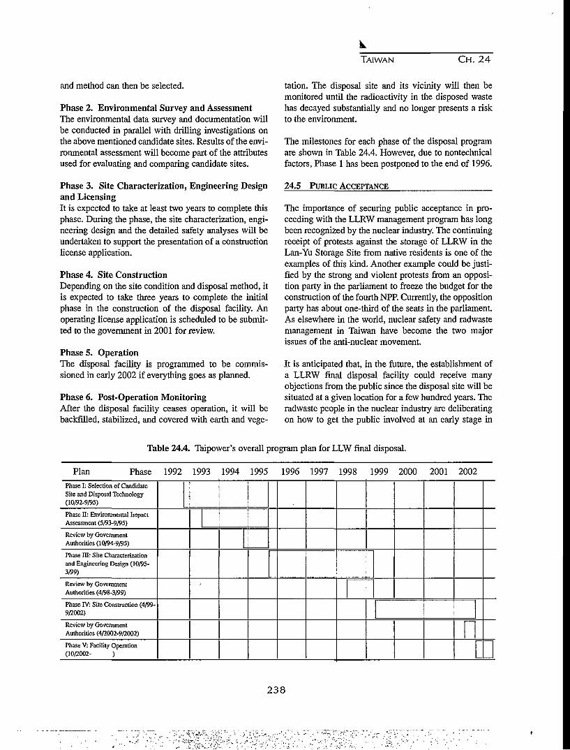
TAIWAN CH. 24
and method can then be selected.
Phase 2. Environmental Survey and AssessmentThe environmental data survey and documentation willbe conducted in parallel with drilling investigations onthe above mentioned candidate sites. Results of the envi-ronmental assessment will become part of the attributesused for evaluating and comparing candidate sites.
Phase 3. Site Characterization, Engineering Designand LicensingIt is expected to take at least two years to complete thisphase. During the phase, the site characterization, engi-neering design and the detailed safety analyses will beundertaken to support the presentation of a constructionlicense application.
Phase 4. Site ConstructionDepending on the site condition and disposal method, itis expected to take three years to complete the initialphase in the construction of the disposal facility. Anoperating license application is scheduled to be submit-ted to the government in 2001 for review.
Phase 5. OperationThe disposal facility is programmed to be commis-sioned in early 2002 if everything goes as planned.
Phase 6. Post-Operation MonitoringAfter the disposal facility ceases operation, it will bebackfilled, stabilized, and covered with earth and vege-
tation. The disposal site and its vicinity will then bemonitored until the radioactivity in the disposed wastehas decayed substantially and no longer presents a riskto the environment.
The milestones for each phase of the disposal programare shown in Table 24.4. However, due to nontechnicalfactors, Phase 1 has been postponed to the end of 1996.
24.5 PUBLIC ACCEPTANCE
The importance of securing public acceptance in pro-ceeding with the LLRW management program has longbeen recognized by the nuclear industry. The continuingreceipt of protests against the storage of LLRW in theLan-Yu Storage Site from native residents is one of theexamples of this kind. Another example could be justi-fied by the strong and violent protests from an opposi-tion party in the parliament to freeze the budget for theconstruction of the fourth NPP. Currently, the oppositionparty has about one-third of the seats in the parliament.As elsewhere in the world, nuclear safety and radwastemanagement in Taiwan have become the two majorissues of the anti-nuclear movement.
It is anticipated that, in the future, the establishment ofa LLRW final disposal facility could receive manyobjections from the public since the disposal site will besituated at a given location for a few hundred years. Theradwaste people in the nuclear industry are deliberatingon how to get the public involved at an early stage in
Table 24.4. Taipower's overall program plan for LLW final disposal.
Plan Phase 1992 1993 1994 1995 1996 1997 1998 1999 2000 2001 2002Phase I: Selection of CandidateSite and Disposal Technology(10/92-9/95)
Phase II: Environmental ImpactAssessment (5/93-9/95)
Review by GovernmentAuthorities (10/94-9/95)
Phase HI: Site Characterizationand Engineering Design (10/95-3/99)
Review by GovernmentAuthorities (4/98-3/99)
Phase IV: Site Construction (4/99-9/2002)
Review by GovernmentAuthorities (4/2002-9/2002)
Phase V: Facility Operation(10/2002- )
U
;
238

TAIWAN C H . 2 4
proceeding with any of the LLRW management pro-grams. To clearly separate the issue of radwaste fromthat of nuclear power plant development may be strate-gically important in resolving the radwaste issue.Nevertheless, both to ensure the safety of the final dis-posal site and to provide a satisfactory financial aid tooffset local objections may be the first two essentialtasks to be worked on among other things.
24.6 CONCLUSIONS AND RECOMMENDATION
Taiwan is a country of scare natural resources of energy,and, therefore, the use of nuclear energy becomes anecessity. The management of radwaste arising from theuse of nuclear power has to be safely planned and imple-mented. To locate a site, as early as possible, to perma-nently accommodate LLRW in Taiwan is considered thetop priority among other management activities. Sincethe country is heavily populated and small in area, itwelcomes any form of regional cooperation in the dis-posal of radwaste. Indeed, international cooperation inradwaste disposal is believed to be of benefit to thewhole world.
It is hoped that an active program of regional coopera-tion on the disposal of LLRW can be initiated by a com-petent organization, such as PBNC (Pacific BasinNuclear Conference), in light of the potential benefits to
this region.
REFERENCES
1. Huang, C. H., Status of radioactive waste manage-ment in Taiwan, in Proc. 1993 InternationalConference on Nuclear Waste Management &Environmental Remediation, Prague, Czechoslo-vakia, 1993.
2. Huang, C.C., Y.T. Shao, and CM. Tsai, How adeveloping country is facing LLW disposal Problem,in the Proc. 1993 International Confer-ence onNuclear Waste Management and Environ-mentalRemediation, Prague, Czechoslo-vakia, 1993.
3. Liu, D.S. Tony, R.T. Lee, and CM. Tsai, Nuclearwaste management in Taiwan - The past three years,in Proc. 1991 Joint International Waste Conference,Seoul, Korea, 1991.
4. Liu, D.S., R.T. Lee, and CM. Tsai, Efforts of lowlevel waste reduction in Taiwan, in Proc. SPEC-TRUM'90, Knoxville, Tennessee, 1990.
5. IAEA, A handbook for guiding good communicationpractices at nuclear fuel cycle facilities, Vienna,1994.
2 3 9

240

CHAPTER 25
PROGRAMME AND RESULTS OF INITIAL PHASE OF RADIOACTIVE WASTEISOLATION IN GEOLOGICAL FORMATIONS IN UKRAINE
D.P. Khrushchov1, andV.M. Starodumov2
1. Institute of Geological Sciences, Chkalov Street 55-b, 252054 Kiev, Ukraine2. State Committee on Nuclear Energy Usage, Bastionnaya Street 9 , 252014 Kiev, Ukraine
Abstract: The concept and a programme for radioactive waste disposal in geological formations of Ukraine havebeen developed. On the basis of certain criteria, an evaluation of the territory of Ukraine has led to the selection ofthree geological regions and three types of formations that are favourable for RAW disposal. The programme ofresearch and development includes three stages: preparatory (1993-95), preparatory/experimental (1995 -2004), andpreparation for construction (2005-2010). The completion of the preparatory stage resulted in the selection of zonesand a number of candidate sites that are favourable for RAW isolation.
25.1 INTRODUCTION
Ukraine has been forced to develop research and devel-opment (R&D) programmes on radioactive waste(RAW) management due to their accumulation in sig-nificant quantities. This is a result of the rapid develop-ment of nuclear power and other RAW-producing indus-tries, as well as the consequences of the Chernobyl dis-aster. According to the generally accepted point of view,a realistic solution for the RAW disposal problem is iso-lation in geological formations. The importance of thisproblem resulted in a research program initiated by theState Committee on Nuclear Power Utilization(Goskomatom), National Academy of Sciences, StateCommittee on Geology, and some other organizations.
The preparatory stage of research on RAW isolation ingeological formations has been completed. Ukrainianscientists have developed the concept and a programmeof R&D (experimental and methodological studies on apilot scale as applied to geological and mining activi-ties). The territory of Ukraine has been assessed as tothe conditions for RAW isolation, and geologicalregions and formations favourable for this purpose havebeen selected. Regional studies, to be discussed below,have resulted in the selection of a number of favourablezones (areas) within these regions, and candidate siteshave been selected. Simultaneously, preliminary analy-ses of the main engineering and construction problemsrelated to RAW isolation have been made.
However, Ukraine is still lagging considerably behind in
the field of R&D as compared to the countries that havebeen developing their programmes over several decades.Ukraine has established scientific relations with special-ists in the field of RAW management. As a result of aninternational conference on "Isolation of RAW inGeological Formations" that was held September 20-24,1994 in Kiev, a basis for cooperation in this field hasbeen initiated with eastern European countries.
Investigations on R&D have been sponsored byGoskomatom partly by finances from budgets of partic-ipating institutions, as well as by special funds from theState Committee on Science and Technology for indi-vidual projects. These investigations are carried out byspecialized multidisciplinary research teams, from 23R&D institutions (Institute of Geological Sciences,State Committee on Geology, Kiev University,Goskomatom, etc.).
25.2 DESCRIPTION O F THE WORK
25.2.1 General Concept
The general concept for RAW isolation in geologicalformations in Ukraine is based on the experience ofadvanced countries, IAEA basic principles and technicalcriteria adapted to geological, socio-economic and eco-logical conditions in the Ukraine1"5. The principle oflong-term (over 10,000 years) RAW isolation is basedon the idea of disposal as a geological engineering sys-tem that must satisfy a range of conditions (final form ofRAW, disposal in deep geological formations at an
241
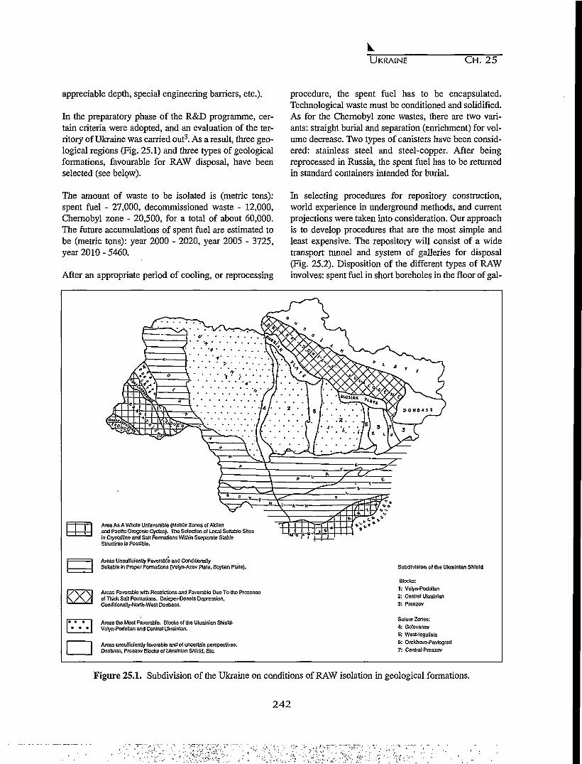
UKRAINE CH. 25
appreciable depth, special engineering barriers, etc.).
In the preparatory phase of the R&D programme, cer-tain criteria were adopted, and an evaluation of the ter-ritory of Ukraine was carried out3. As a result, three geo-logical regions (Fig. 25.1) and three types of geologicalformations, favourable for RAW disposal, have beenselected (see below).
procedure, the spent fuel has to be encapsulated.Technological waste must be conditioned and solidified.As for the Chernobyl zone wastes, there are two vari-ants: straight burial and separation (enrichment) for vol-ume decrease. Two types of canisters have been consid-ered: stainless steel and steel-copper. After beingreprocessed in Russia, the spent fuel has to be returnedin standard containers intended for burial.
The amount of waste to be isolated is (metric tons):spent fuel - 27,000, decommissioned waste - 12,000,Chernobyl zone - 20,500, for a total of about 60,000.The future accumulations of spent fuel are estimated tobe (metric tons): year 2000 - 2020, year 2005 - 3725,year 2010 - 5460.
After an appropriate period of cooling, or reprocessing
In selecting procedures for repository construction,world experience in underground methods, and currentprojections were taken into consideration. Our approachis to develop procedures that are the most simple andleast expensive. The repository will consist of a widetransport tunnel and system of galleries for disposal(Fig. 25.2). Disposition of the different types of RAWinvolves: spent fuel in short boreholes in the floor of gal-
-p*
Area As A Whole Unfavorable (Mobile Zones of Aldianand Pacific Orogcnic Cydes). The Selection of Local Suitable Sitesin Crystalline and Salt Formations Within Sseparate StableStructires is Possible.
Areas Unsufficiently Favorable and ConditionallySuitable in Proper Formations (Volyn-Azov Plate, Scytian Plate).
«
S?.
/ \ / \ l Areas Favorable with Restrictions and Favorable Due To the Presencey / ^ / j of Thick Salt Formations. Dnieper-Donets Depression,
Conditionally-North-West Donbass.
• • • I Areas the Most Favorable. Blocks of the Ukrainian Shield-* * * | Volyn-Podolian and Centra) Ukrainian.
Areas unsufficiently favorable and of uncertain perspectives.Donbass, Preazov Blocks of Ukrainian Shield, Etc
Subdivision of the Ukrainian Shield
Blocks:1: Volyn-Podolian2: Central Ukrainian3: Preazov
Suture Zones:4: Golovanev5: West-lnguliets6: Orekhovo-Pavlograd7: Central-Preazov
Figure 25.1. Subdivision of the Ukraine on conditions of RAW isolation in geological formations.
242
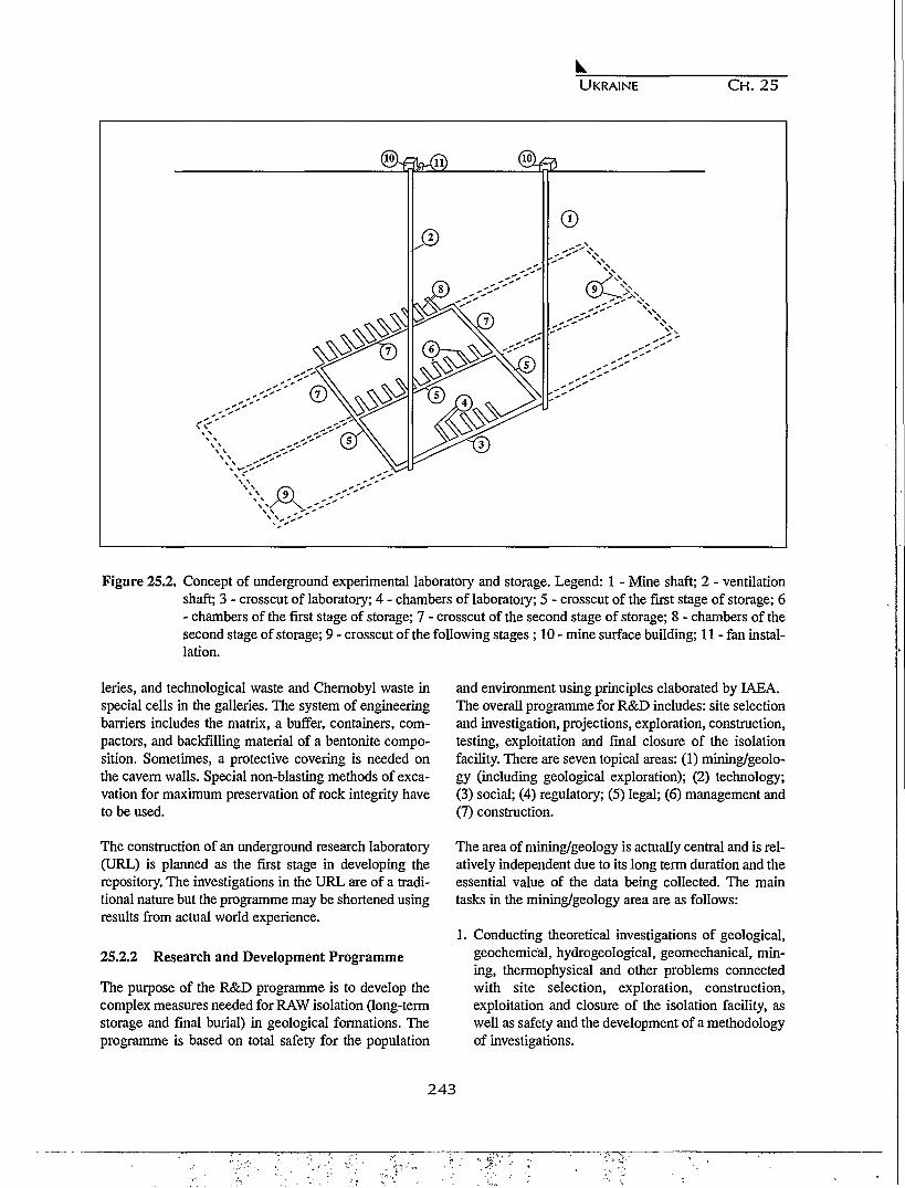
UKRAINE CH. 25
Figure 25.2. Concept of underground experimental laboratory and storage. Legend: 1 - Mine shaft; 2 - ventilationshaft; 3 - crosscut of laboratory; 4 - chambers of laboratory; 5 - crosscut of the first stage of storage; 6- chambers of the first stage of storage; 7 - crosscut of the second stage of storage; 8 - chambers of thesecond stage of storage; 9 - crosscut of the following stages; 10 - mine surface building; 11 - fan instal-lation.
leries, and technological waste and Chernobyl waste inspecial cells in the galleries. The system of engineeringbarriers includes the matrix, a buffer, containers, com-pactors, and backfilling material of a bentonite compo-sition. Sometimes, a protective covering is needed onthe cavern walls. Special non-blasting methods of exca-vation for maximum preservation of rock integrity haveto be used.
The construction of an underground research laboratory(URL) is planned as the first stage in developing therepository. The investigations in the URL are of a tradi-tional nature but the programme may be shortened usingresults from actual world experience.
25.2.2 Research and Development Programme
The purpose of the R&D programme is to develop thecomplex measures needed for RAW isolation (long-termstorage and final burial) in geological formations. Theprogramme is based on total safety for the population
and environment using principles elaborated by IAEA.The overall programme for R&D includes: site selectionand investigation, projections, exploration, construction,testing, exploitation and final closure of the isolationfacility. There are seven topical areas: (1) mining/geolo-gy (including geological exploration); (2) technology;(3) social; (4) regulatory; (5) legal; (6) management and(7) construction.
The area of mining/geology is actually central and is rel-atively independent due to its long term duration and theessential value of the data being collected. The maintasks in the mining/geology area are as follows:
1. Conducting theoretical investigations of geological,geochemical, hydrogeological, geomechanical, min-ing, thermophysical and other problems connectedwith site selection, exploration, construction,exploitation and closure of the isolation facility, aswell as safety and the development of a methodologyof investigations.
243

UKRAINE CH. 25
2. Evaluation of the territory of Ukraine from the pointof view of RAW disposal.
3. Regional studies to elaborate on selection criteria,structures and the selection and evaluation of sites.
4. Supervision of exploration on selected structures andsites.
5. Construction of URL to carry out selected experi-ments.
6. Perfection of construction and technological parame-ters for the RAW isolation facility based on the syn-thesis of exploration data, experiments in the URLetc.
7. Develop a prognosis for the functioning of the isola-tion facility under the influence of the effects of geo-logical evolution and scenaria of possible catastroph-ic events (safety analysis).
8. Develop a monitoring system and system of control(management).
9. Provide a basis for controlling construction of theRAW isolation facility.
10. Provide a basis for supervising the exploitation andclosure of the facilities.
The programme of R&D includes the following stages:
1. Preparatory -1993-95Goal: elaboration of concepts, selection of sites,exploration;
2. Preparatory/experimental - 1996-2004Goal: exploration, construction of URL, collection ofexperimental data during construction and exploita-tion of the isolation facility, and
3. Preparation for construction - 2005-2010Goal: final preparation for construction of RAW iso-lation facility (eventually the beginning of the con-struction).
The durations of these stages are not yet firm and willactually depend on the financial situation.
25.2.3 Methodology of Scientific Investigations.
The generally accepted concept of the repository as amultibarrier, geological/engineering system takes intoaccount that the rock formation, as a main barrier, is theleading factor in determining the safety of long term iso-lation. That is why a comprehensive investigation of thegeological environment provides a foundation for inves-tigations in the area of mining/geology.
The final goal in the preparatory stage of the R&D pro-gramme is the selection of site(s) for the isolation of
RAW. This goal can be achieved by solving the follow-ing tasks in a proper hierarchical sequence that is corre-lated with the stages of programme investigations men-tioned above:
1. Evaluation of the territory of Ukraine from the pointof view of RAW isolation;
2. Selection of geological regions and formationspotentially favourable for RAW isolation;
3. Regional analysis of potentially favourable forma-tions in a hierarchical sequence. Region-Zone (groupof structures)-Local Structure (site), (Fig. 25.3); and
4. Selection and evaluation of sites.
Tasks 1-3 and part of 4 have already been accomplished.
As a result of the evaluation and ranking of 12 geologi-cal regions in Ukraine, only three have been selected asfavourable for RAW disposal: (1) Ukrainian shield; (2)Dnieper-Donets depression; and, (3) northwesternDonbass. Conditionally, the southwestern slope of theeast European platform of the ancient Volyn-Azov plateis under investigation.
The selection of formations in these regions was madeon the basis of an initial evaluation of parameters and byanalogy with world experience. By mean of thisapproach, three types of potentially favourable forma-tions have been selected: crystalline, salt and argila-ceous. The next step was to carry out a regional analysisof formations.
The hierarchical sequence of investigations (Regional-Zonal-Local) is similar for all formations. The method-ology of the selection process on these three levels isbased on the usage of a set of mining/geology area mod-els, categorized on different scales according to the levelof investigation.
The results of this selection of a set of models (as wellas data from social, economic, ecological and otherstudies) provide the basis for setting up criteria for theselection, comparison, estimation and ranking on zonaland local levels. This set includes three groups of prac-tically equal importance:
I. Safety (technical-geological)a. tectonicb. neotectonicc. seismicd. hydrogeologice. type of formation
244

Ul
Ukrainian Shield
Korosten Pluton (zone)
Piatikhatki Massif (zone)
10
Volodarsk-Volynskiy Massif
7\
iz
Figure 25.3. Principles of site selection in Ukrainian shield: I - Volyn, II - Podolia, III - Bielaya Cerkva, IV - Kirovograd, V - Near-Dnieper, VI - Near-AzovPavlograd, VII - West Ingoulets, VIII - Golovanev, IX - Orechovo. Legend: 1 - alkaline syenites; 2 - monzonites, gabbro monzonites: 3 - olivinegobbros, rarely gabbro-peridotites, gabbro-pyroxenites; 4 - granite-porphyries, rapakivi and rapakivi-like granites; 5 - dikes of diabase and gab-bro-diababase; 6 - anorthosites, gabbro-anorthosites; 7 - norites, gabbro-norites; 8 - granites (Zhitomir and Kirovograd types); 9 - biotite gneiss,quartzitic sandstones; 10 - plagiomigmatites, plagiogranites; 11 - granites, migmatites; 12 - biotite granites, aplitic and pegmatoid granites; 13- tonalites, plagiogranites, plagiomigmatites; 14 - andesite and diabase metaporphyry amphibolites; 15 - graphitic and biotites shales, metasand-stones; 16 - faults.
nI
UKRAINE CH. 25
f. goemechanicg. geochemistry (including waste composition)h. geomorphologici. hydrologicj . climatick. technogenic/ecologic conditions1. mineral deposits
II. Social-politicala. demographicb. psychologicc. contamination from Chernobyl
HI. Technologic complexitya. construction costb. technologic complexity
On the zonal and local levels, the results of the social-economic and ecological investigations must be devel-oped in different degrees of detail.
In the areas of mining/geology, the set of models that arebeing used in the hierarchical sequence of regionalinvestigations includes both static and dynamic aspects.The dynamic aspect must consider two variants: evolu-tionary and revolutionary (catastrophic, or maximumproject risk). Every model has its own tasks, objects andphenomena for investigation, but all models are inte-grated within the whole set. An understanding of thefunctioning of the disposal facility has to be developedfrom an appropriate synthesis of these models.
These models are developed using three kinds of data:theoretical, computational (mathematical, statistical,probabilistic) and experimental. The experimental dataare obtained as a result of URL investigations. Thedimensions of these models are generally known: nearfield and far field. The objectives of the investigationsfor this work are well described in the literature. Themain task in analyzing the functioning of a disposalfacility is the prognosis of its long term safety. Thisprognosis has to be developed within a framework thatincludes scenaria of evolutionary and catastrophic phe-nomena. One of the terminal tasks of modelling is theestimation of radionuclide behaviour in the biosphere(accumulations in surface waters, sorption by clays andorganic matter etc.). The monitoring of an RAW dispos-al facility may be realized in the near field by means ofdirect observations in situ; in far field, by mean of spe-cial boreholes and surface observations.
25.3 RESULTS O F REGIONAL STUDIES
Regional studies have been carried out in the UkrainianShield, Dnieper-Donets Depression and Donbass.
In the Ukrainian shield (Fig. 25.3), two zones have beenselected as favourable for RAW disposal: (1) Korostenpluton and a group of structures in the middle of theNear-Dnieper area, where the preferable type of rocks,granites and gabbro-anorthosites of Proterozoic age arefound; and (2) in salt domes of the Dnieper-Donetsdepression in the northeastern, and southwestern mar-ginal zones, and in the southeastern part of the Donbassdepression, in bedded salt formations. Argillaceous for-mations of sufficient thickness are spread over thesouthwestern slope of the east-European platform(Volyn-Asov plates, Cambrian, Oligocene), and in theDonbass-Dnieper-Donets depression. In the latter loca-tions, detailed geological investigations have not yetbeen carried out.
In the course of regional studies, several candidate siteshave been chosen. In the northern part of the Korostenpluton, two favourable massifs (subzones) have beenselected, i.e. Luginy and Volodarsk-Volyn massifs. TheLuginy massif is composed primarily of granite-rapakivi, and two sites within its limits have been cho-sen. Eight salt domes that are potentially favourable forRAW disposal have been selected within the boundariesof the Dnieper-Donets depression.
On the basis of the mining/geology models and consid-ering the criteria mentioned above, a ranking of selectedsites has been made. Crystalline formations within theKorosten pluton have been ranked as follows: (1) firstpriority for the Pribytkov and Doroginby sites in theLuginy massif; and (2) second priority for the Novo-Borovaya and Zankovo sites in the Volodarsk-Volynmassif. Within the limits of the Dnieper-Donets depres-sion, sites have been ranked as follows: (1) first priorityfor the Kaplintsy, Isachki and Yatsyno-Logoviki saltdomes in the northeastern marginal zone; (2) second pri-ority for the Dmitrievka, Siniovka, and Romny saltdomes in the southwestern marginal zone; and (3) thirdpriority for the Aleckseevka salt dome in the southeast-ern part of the depression.
Two zones of Permian bedded salt formation have beenstudied in northwestern Donbass.
246
UKRAINE C H . 2 5
25.4 CONCLUSIONS
As a result of completing the initial stage of the R&Dprogramme, certain regional studies have been carriedout. The regional studies resulted in the selection offavourable zones of crystalline formations in theUkrainian shield and salt formations in the DnieperDonets depression (as well as in northwestern Donbass,where technogenetic activities have to be considered.)Several candidate sites have been selected in favourablezones. The completion of this initial stage leads to thenext stage of specialized exploratory geological/geo-physical investigations. This stage is much more com-plicated and much more expensive.
The initial stage of investigations was completed during1993-95. Such rapid advances were possible due to athorough understanding of the geology of the territoryof Ukraine, the excellent work of the scientific team,and the availability of results from world experience inthe field of RAW in advanced countries (USA, Franceetc.).
Ukraine possesses scientific and technological capabili-ties sufficient for the effective completion of the neces-sary R&D related to exploration and URL construction.But the actual economy in the Ukraine provides no rea-son for optimism that financing sufficient for an effec-tive realization of such an expensive program will beforthcoming. Thus, the possibilities for program supportwill depend upon a significant increase in national fundsand the organization of international cooperation.
The Institutions involved in R&D programmes in wasteisolation (as well as the Ministry of EnvironmentProtection and Nuclear Safety) and the State Committeeon Nuclear Energy Utilization, as a sponsoring institu-tion, have initiated an annual international conference,"Isolation of RAW in Geological Formations." The first
conference was held September 20-24, 1994 in Kiev.This conference has revealed the interest of easternEuropean countries (Poland, Slovakia, the CzechRepublic, Russia, Hungary, Slovenia, Belarus, etc.) in aprogram of cooperation. A second conference is sched-uled to be held in 1995.
ACKNOWLEDGEMENTS
Material submitted by V.P. Cherniak, G.I. Chernyi, L.S.Galetskiy, O.M. Kharitonov, V.I. Lialko, V.P. Palienko,Y.N. Shelkoplias, S.B. Shekhunova, E.A. Yakovlev hasbeen used in preparing this paper.
REFERENCES
1. Geological Problems in Radioactive Waste Isolation,A World Wide Review, ed. P.A. Witherspoon,Lawrence Berkeley Laboratory, Rept. LBL-29703, p.233,1991
2. Barr, G.E and E. Dunn, A working definition of sce-naria and a method of scenario construction,Proceedings of the Fourth International Conferenceon High Level Radioactive Waste Management, LasVegas, NV, pp. 1093-1098, April 26-30,1993.
3. Khruschov D.P., V.I. Lialko, and O.M. Kharitonov,Isolation of radioactive wastes in geological forma-tions of Ukraine, p.60, Preprint of Inst. of Geo. Sci.,ed. Naukova Dumka, Kiev, 1993. (in Russian)
4. Radioactive Waste Management, an IAEA sourcebook, p. 274, IAEA, Vienna, 1992.
5. Safety Principles and Technical Criteria for theUnderground Disposal of High-Level RadioactiveWaste, p. 33, IAEA Division of Nuclear Fuel Cycle,Vienna, 1989.
247
248
;,.-•;. y<V>-
CHAPTER 26
THE INVESTIGATIONS OF THE GEOLOGY AND HYDROGEOLOGY AT
SELLAFIELD IN THE UNITED KINGDOM
Robert Chaplow
United Kingdom Nirex Limited, Harwell, Oxfordshire OX11 ORH, UK
26.1 INTRODUCTION 26.2 SCOPE OF INVESTIGATIONS
United Kingdom Nirex Limited (Nirex) is responsiblefor providing and managing a national disposal facilityfor solid intermediate-level (ILW) and low-level (LLW)radioactive waste. Such wastes have been produced inthe UK for over 40 years and have come from the nuclearpower industry, medical and defense establishments, aswell as from other research and industrial sources. UKGovernment policy is to dispose of these wastes in adeep underground repository. Similar policies are fol-lowed by other countries which produce substantialquantities of long-lived radioactive waste.
Following an extensive site selection exercise, Nirexannounced in 1989 that it would investigate, initially,sites at Dounreay in Caithness and Sellafield in Cumbria,to establish their suitability as safe locations for a deepdisposal facility for ILW and LLW. Initial boreholes andother geological and geophysical surveys subsequentlyindicated that the geology at both sites had the potentialto meet the demanding safety requirements for a deeprepository. In July 1991, Nirex announced that it was toconcentrate its further investigations at Sellafield. Giventhat there appeared to be little otherwise to distinguishbetween the overall suitability of the two sites, transportof waste and the associated costs were major considera-tions in this decision; an estimated 60 per cent by volumeof the radioactive waste destined for the repository aris-es from British Nuclear Fuels' operations at Sellafield.
This paper presents a broad overview of the investiga-tions carried out at Sellafield, up to approximately theend of 1994 and of the results obtained. A description isprovided of the strategy being adopted for the continuedinvestigation of the site. Descriptions of the geology,hydrogeology and geochemistry studies at Sellafield areprovided by Michie (1996), Sutton (1996), and Bath, etal., (1996).
26.2.1 Scientific Approach
Nirex has adopted a systematic scientific approach to thedesign and implementation of the investigations. A widerange of technical specialists and techniques have beenused in the conduct of the work and care has been takento avoid undue reliance on any single technique in theinterpretation of the ground conditions. The quality ofthe work being undertaken by Nirex has been recognizedby independent reviewers, for example, by the RoyalSociety Study Group (1994) and RWMAC (1994).
Nirex makes information from the investigations widelyavailable through publications and presentations. Aseries of papers on the geology of the Sellafield areawere presented at a meeting of the Yorkshire GeologicalSociety in late 1993) and subsequently published(Holliday and Rees, 1994). A second meeting on thehydrogeology was held at the Geological SocietyApartments in May 1994, the papers presented at thismeeting have been submitted for publication. Nirex alsoreleases a significant number of detailed reports on theresults of the investigations (For example: Nirex, 1992Nirex, 1993a-i, Nirex, 1994a-b). An independent panelof university professors carries out review of the workundertaken by Nirex. The first Annual Report of thisreview panel was released in December 1994.
26.2.2 Areas of Study
The studies carried out in West Cumbria have been con-tained within three areas (Fig. 26.1):
1. An area onshore and offshore (A) of approximately60 km by 65 km for which information has been gath-ered on geological features which might have rele-vance to a repository safety assessment, using exist-
2 4 9
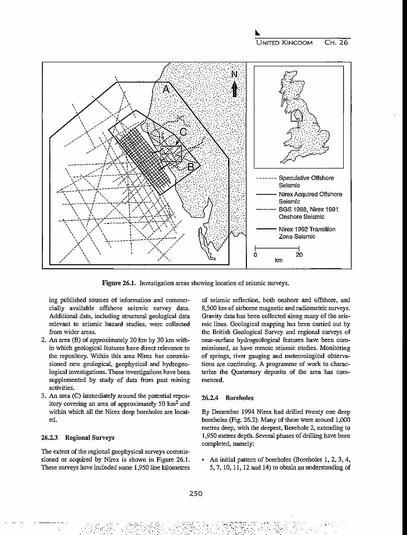
UNITED K I N G D O M C H . 26
Speculative OffshoreSeismicNirex Acquired OffshoreSeismicBGS 1988, Nirex 1991Onshore Seismic
Nirex 1992 TransitionZone Seismic
km20
Figure 26.1. Investigation areas showing location of seismic surveys.
ing published sources of information and commer-cially available offshore seismic survey data.Additional data, including structural geological datarelevant to seismic hazard studies, were collectedfrom wider areas.
2. An area (B) of approximately 20 km by 30 km with-in which geological features have direct relevance tothe repository. Within this area Nirex has commis-sioned new geological, geophysical and hydrogeo-logical investigations. These investigations have beensupplemented by study of data from past miningactivities.
3. An area (C) immediately around the potential repos-itory covering an area of approximately 50 km2 andwithin which all the Nirex deep boreholes are locat-ed.
26.2.3 Regional Surveys
The extent of the regional geophysical surveys commis-sioned or acquired by Nirex is shown in Figure 26.1.These surveys have included some 1,950 line kilometres
of seismic reflection, both onshore and offshore, and8,500 km of airborne magnetic and radiometric surveys.Gravity data has been collected along many of the seis-mic lines. Geological mapping has been carried out bythe British Geological Survey and regional surveys ofnear-surface hydrogeological features have been com-missioned, as have remote seismic studies. Monitoringof springs, river gauging and meteorological observa-tions are continuing. A programme of work to charac-terize the Quaternary deposits of the area has com-menced.
26.2.4 Boreholes
By December 1994 Nirex had drilled twenty one deepboreholes (Fig. 26.2). Many of these were around 1,000metres deep, with the deepest, Borehole 2, extending to1,950 metres depth. Several phases of drilling have beencompleted, namely:
• An initial pattern of boreholes (Boreholes 1, 2, 3, 4,5,7,10,11,12 and 14) to obtain an understanding of
2 5 0

UNITED K I N G D O M C H . 26
•BH14>.v• " • • ' • • ' . • • •
BOREHOLES
• Drilled
O RCF/RCM Boreholes
"A Rock Characterization_\ Facility (RCF)
p | Potential RepositoryZone (PRZ)
£2 Built-up Area
) Main Roads
I 10 1000
Metres
COVER ROCKS
Q Sandstone
^ ] Brockram
BASEMENT
F-l Volcanic
Figure 26.2. Schematic location of Nirex boreholes within the Sellafield site area, December 1994.
the regional geological and hydrogeological settingof the site.
• A subsequent series of boreholes to investigate spe-cific aspects of the site. Boreholes 8 and 9 have beendrilled in the upper part of the catchment to investi-gate groundwater recharge and Borehole 13 hasinvestigated the area to the south where the thicknessof the Permo-Triassic sequence increases markedly.
• A series of six boreholes (RCF1 to 3) and RCM1 to3 have been drilled in the area of the proposed RockCharacterization Facility to characterize the groundin advance of underground excavation and to permitinstallation of a groundwater monitoring systemclose to the proposed shafts (Nirex, 1994b).
• Inclined boreholes are being drilled to characterizeparts of the potential repository zone. BoreholesPRZ2 and 3 are completed; PRZ1 has still to be com-pleted.
Two boreholes, drilled by others several decades ago formineral exploration purposes, have been instrumented tosupplement the groundwater monitoring system.The majority of the drilling carried out by Nirex hasbeen to obtain continuous core which is used fordetailed characterization of the rock penetrated.
Geophysical logging is also carried out to determinerock properties and particularly to provide informationon the characteristics of the fractures which occur in therocks.
Hydrogeological testing is carried out in the boreholesto determine groundwater pressures and the hydraulicconductivity of the rocks, that is, their ability to transmitwater. Testing is carried out during breaks in the drillingand after completion of drilling to investigate thehydraulic properties of the rocks at a range of scales(Fig. 26.3).
Sampling of groundwater and analysis of samples isroutinely undertaken during drilling and subsequently.Special measures are taken to reduce the levels of cont-amination of the groundwater by drilling fluids and toquantify the extent of any contamination to permit thedetermination of groundwater chemistry.
The completed boreholes are also used for undertakingspecialist testing programmes. Examples include cross-hole seismic tomography and cross-hole hydraulic test-ing. A major programme of pump testing to measure theresponses of the groundwater system over a wide area to
251

kUNITED KINGDOM CH. 26
Field Activity
Standard Well Testing
Borehole 2/4 crosshole
Fracture Network Testing
Short Interval Testing
RCF3 Pump Test
PRZ Monitoring Network
Tracer Tests
RCF
Scale
10m
100-500m
10-100m
1-5m
Up to km
All10-100m
All
HydraulicConnections
Hydraulic to Overlying Calibration/ TransportCharacteristics Units Validation Processes
• •
• Partially
••
• •
•• •
• •
Figure 26.3. Types of hydrogeological testing.
pumping from a central borehole is currently inprogress.
26.2.5 Long-Term Monitoring
Most of the boreholes have now been converted forlong-term monitoring of groundwater pressures by theinstallation of Westbay multi-level groundwater moni-toring systems. These systems permit measurements ofgroundwater pressures within selected sections of theboreholes. Many sections are now equipped with auto-matic logging systems which provide measurements ofpressures at two minute intervals to a high level of pre-cision (Nirex, 1994a).
Nineteen boreholes have Westbay strings installed, anda further borehole is equipped with an alternative moni-toring system. Some of the monitoring strings areamongst the most complex and deepest instrumentationsystems of their type ever installed.
The monitoring network is designed to establish base-line groundwater conditions and to provide the meansfor monitoring the response of the groundwater systemto induced perturbations, such as from cross-hole test-ing, pumping tests and RCF shaft excavation.
26.3 SUMMARY OF RESULTS
26.3.1 Geology
The proposed repository host rock at Sellafield compris-es the volcanic rocks of the Ordovician BorrowdaleVolcanic Group. Within the potential repository zone,
the top surface of volcanic rocks is at a depth of 400 to600 metres, occurring beneath the immediately overly-ing Permian breccia, the Brockram (Fig. 26.4). This is inturn, overlain by the Triassic Sandstones of theSherwood Sandstone Group. The top of the volcanicrocks dips to the west such that at the coast they aresome 1,600 metres below the surface. On approachingthe margins of the East Irish Sea Basin, the SherwoodSandstone Group is underlain by a thicker sequence ofPermian rocks comprising the St. Bees Shale, the StBees Evaporite and the Brockram. These are in turnunderlain by the Carboniferous Limestone which restsunconformably on the Borrowdale Volcanic Grouprocks (Michie, 1996; Holliday and Rees, 1994).
The rocks have been subjected to numerous periods offaulting and folding during their geological history. Thedistribution of the various formations at depth and thelocations of the faults which cut them have been definedprimarily by interpretation of the seismic reflection data,calibrated by the deep boreholes and utilizing mine plandata for the area to the north of Sellafield. Structure con-tour maps covering areas A and B have been generatedfor all the major geological boundaries within thesequence (Nirex, 1993a, b). Within the potential reposi-tory zone, additional detail is now being added basedupon further boreholes, seismic reflection surveys,cross-hole tomography surveys between sets of co-pla-nar boreholes and complex analysis of existing verticalseismic profiling (VSP) data.
26.3.2 Hydrogeology
Much of the work being undertaken by Nirex at
252
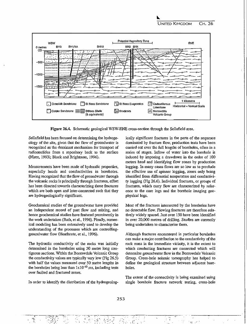
UNITED KINGDOM C H . 26
wsw0 metres BH3
0 D -
BH1/1A BH10
Potential Repository Zone
BH2 BH4ENE
-500-
-1000-
-1500-
[ 7 ] Ormskirk Sandstone [ ^ St Bees Sandstone [ \ ] St Bees Evaporates
$5] Brockram] Calder Sandstone = ^ S t B e e s Shale(& equivalents)
, 1 kilometre1 Carboniferous ' '
Limestone Honzontal = Vertical Scale] BorrowdaleVolcanic Group
Figure 26.4. Schematic geological WSW-ENE cross-section through the Sellafield area.
Sellafield has been focused on determining the hydroge-ology of the site, given that the flow of groundwater isrecognized as the dominant mechanism for transport ofradionuclides from a repository back to the surface(Nirex, 1993i; Black and Brightman, 1996).
Measurements have been made of hydraulic properties,especially heads and conductivities in boreholes.Having recognized that the flow of groundwater throughthe volcanic rocks is principally through fractures, efforthas been directed towards characterizing those fractureswhich are both open and inter-connected such that theyare hydrogeologically significant.
Geochemical studies of the groundwater have providedan independent record of past flow and mixing, andhence geochemical studies have featured prominently inthe work undertaken (Bath, et al., 1996). Finally, numer-ical modeling has been extensively used to develop theunderstanding of the processes which are controlling-groundwater flow (Heathcote, et al., 1996).
The hydraulic conductivity of the rocks was initiallydetermined in the boreholes using 50 metre long con-tiguous sections. Within the Borrowdale Volcanic Groupthe conductivity values are typically very low (Fig 26.5)with half the values measured over 50 metre lengths inthe boreholes being less than lxlO"10 ms, including testsover faulted and fractured zones.
In order to identify the distribution of the hydrogeolog-
ically significant fractures in the parts of the sequencedominated by fracture flow, production tests have beencarried out over the full lengths of boreholes, often in aseries of stages. Inflow of water into the borehole isinduced by imposing a drawdown in the order of 100metres head and identifying flow zones by productionlogging. In many cases flows are so low as to precludethe effective use of spinner logging, zones only beingidentified from differential temperature and conductivi-ty logging (Fig 26.6). Individual fractures, or groups offractures, which carry flow are characterized by refer-ence to the core logs and the borehole imaging geo-physical logs.
Most of the fractures intersected by the boreholes haveno detectable flow. Flowing fractures are therefore rela-tively widely spaced. Just over 150 have been identifiedin over 20,000 metres of drilling. Studies are currentlybeing undertaken to characterise them.
Although fractures encountered in particular boreholescan make a major contribution to the conductivity of therock mass in the immediate vicinity, it is the extent towhich conducting fractures are connected which willdetermine groundwater flow in the Borrowdale VolcanicGroup. Cross-hole seismic tomography has helped todefine the geological structure between adjacent bore-holes.
The extent of the connectivity is being examined usingsingle borehole fracture network testing, cross-hole
253

UNITED KINGDOM C H . 26
99-
I 95'§ • 9 0 -
" - 8 0 -S> 70-
| 50-
•a 20-
1 10-3 5-
1 -
0.1-
I
BVG Reid K
BVG Core KGh
St Bees Sandstone t
St Bees Sandstone (
J
rield K
Sore Kr.
^ ^
1
f"r >
/
y
f
y
i
y
i
;
1
-13 -12 -11 -10 -9 -8
Log Hydraulic Conductivity (Log ms"1)
-7
Figure 26.5. Summary of hydraulic conductivity values.
Sonic Imagery Differential Differential Lithographyof Borehole Wall Temperature Log Conductivity Log Structure
715
720
725
730
735
740
745
750
755
760 <-
metres belowrotary table
DT/DZ(C/km)
50 -100
. FlowZone 5
Generallyfresh
homogeneousfine grained
TUFF
Fault T350/80 E
Moderatelyaltered
FlowZone 6
Moderately
altered
FlowZone 7Fault -g"350/80 E
DT/DZ(mS/cm/km)
100
715
720
725
730
735
740
745
750
755
-•760
mbrt
Figure 26.6. Identification of flow zones in Borehole 2.
254

UNITED KINGDOM C H . 26
-30
82H% -40
-50
COLDER RECHARGEOLDER GROUNDWATER
INCREASINGSALINITY(BRINES)
Average Recent Rainfall, Sellafield
Coastal Zone
Lake District Springs, Seeps and Groundwaters
• Intermediate
Deeper Repository Zone
- 7 - 6
818H%
Figure 26.7. Stable isotopic discrimination between groundwaters with different origins.
hydraulic testing and by a series of large scale pumptests. Preliminary results from recent testing suggest thatthe fracture network may be less well connected thanpreviously considered to be the case.
26.3.3 Geochemistry
Geochemical studies (Bath, et al., 1996) are carried outfor three reasons: (a) to support the development of aconceptual model of the present-day hydrogeology, (b)to investigate how the groundwater system has evolvedover time; and (c) to characterize the baseline hydro-chemical conditions to support other studies.
Considerable progress has been made and the presentdataset has contributed substantially to the constructionof a conceptual model of the hydrogeological system, onwhich numerical modeling can be based. Some hydro-chemical aspects of the conceptual model (particularlysalinity sources and mixing zones) will provide specifictests of the adequacy of numerical modeling.
The palaeohydrogeology of the area is dominated by itslocation on the margin of the East Irish Sea Basin. Theinfluence of basinal brines has been a feature of the deep
sediments and the Borrowdale Volcanic Group basementin the west of the area for considerable geological time.Within the potential repository zone, a range of analysesincluding stable isotopic and noble gas temperature datafor groundwaters in the Borrowdale Volcanic Groupbasement suggests that the waters at depth are clearlydistinguishable from the shallow groundwaters and frommodern rainfall (Fig. 26.7), and that the deeper watersprobably have long residence times. This is a consistentpattern shown by several independent determinants andstudies (Bath, et al., 1996).
26.3.4 Hydrogeological System
The current conceptual model of the hydrogeologicalsystem is illustrated in diagrammatic form in Figure26.8. The three component parts of the system: the IrishSea Basin Regime, the Hills and Basement Regime, andthe Coastal Plain Regime are essentially as defined inmid 1992 (Nirex, 1992), although greater confidence inthis model has been obtained with the availability ofgeochemical data.
The conceptual model and its evolution are supported,not only by geological, hydrogeological and geochemi-
255

UNITED KINGDOM CH. 26
Coastal Plain Regime
0 metresOD
-500
-1000
-1500
WSW ENE
1 kilometre
Horizontal = Vertical Scale
Groundwater FlowDirection
Q Freshwater__= Brine
UT\ Saline
Figure 26.8. Current conceptual model of the groundwater system in the Sellafield area.
cal studies, but also by a range of numerical modelingstudies which have served to examine and test a series ofconcepts concerning the behavior of individual compo-nents of the total system (Heathcote, et al., 1996).
26.4 FURTHER STUDIES
The investigations carried out to date from the surfaceare providing Nirex with a good understanding of thegeological and hydrogeological conditions at Sellafieldas they affect the decision on whether or not the site willbe suitable for the construction of a repository to meetthe stringent regulatory safety targets. Further investiga-tions from the surface are in progress or are planned tofurther characterize specific features of the site. In par-ticular, the pump test in Borehole RCF3 and the contin-ued monitoring of groundwater conditions utilizing theinstalled instrumentation system are important compo-nents of this forward programme.
Investigations from the surface are, however, unable toresolve all the remaining uncertainties regarding thecharacteristics of the site. Nirex, in line with similaragencies in other countries, considers that a phase ofinvestigations carried out underground from a suitablyconstructed experimental facility is a logical and essen-tial extension to characterization from the surface. Forthis reason, Nirex has applied for planning permission toconstruct an underground Rock CharacterizationFacility (RCF) at the Longlands Farm site at Sellafield.This application is the subject of an appeal by Nirex
against refusal, by Cumbria County Council, of plan-ning permission.
26.5 CONCLUSIONS
The following conclusions are drawn from the investi-gations carried out at Sellafield:
1. An extensive programme of investigations has beencarried out by Nirex. Various independent reviewershave commented on the high quality of the workundertaken.
2. The geological succession and structural geology ofthe site has been determined in significant detail.
3. Cross-hole seismic tomography has demonstratedthat the geological structures can be mapped betweenboreholes. This observation is providing added confi-dence regarding the definition of the geologicalstructure within the Borrowdale Volcanic Group andits influence on the hydraulic conductivity of the rockmass.
4. Preliminary quantitative assessments have beenmade of the distribution of hydraulic conductivityvalues in all the major hydrogeological units. Valuesmeasured in the Borrowdale Volcanic Group are typ-ically low.
5. A limited number of individual fractures has beenidentified in the Borrowdale Volcanic Group alongwhich groundwater flows. These fractures form anetwork which controls the flow of water through therocks. Nirex is currently assuming that the fracture
256
- •••-?•-<,•-

UNITED KINGDOM CH. 26
network is well connected. Preliminary results fromrecent testing suggest that the fracture network maybe less well connected than previously considered tobe the case.
6. Geochemical and isotopic analysis of groundwatersamples have assisted the development of the hydro-geological conceptual model and are helping to givesome indication of the age and provenance of thegroundwater within the Borrowdale Volcanic Grouprocks. Evidence is suggesting that the deeper ground-water in the potential repository zone is old.
7. Good progress has been made with the investiga-tions, and with the interpretation and modeling stud-ies which follow on, to determine whether or not thesite is suitable as a potential repository. However,much work remains to be done to resolve uncertain-ties and to develop confidence in the understandingof the site and the models which are constructed torepresent its behavior. Construction of an under-ground Rock Characterization Facility forms a logi-cal and essential continuation to the investigationscarried out from the surface to progressively reduceuncertainty and to provide the information necessaryto determine the suitability of the site for construc-tion of a deep radioactive waste repository to meetthe stringent regulatory safety requirements.
REFERENCES
Bath, A. H., R. A. McCartney, H. G. Richards, R.Metcalfe, and M. B. Crawford, Groundwater chem-istry in the Sellafield area: a preliminarty interpreta-tion, Quarterly Journal of Engineering Geology, 29,S39-S57, 1996.
Black, J. H., and M. A. Brightman, Conceptual model ofthe hydrogeology of Sellafield, Quarterly Journal ofEngineering Geology, 29, S39-S57,1996.
Heathcote, J. A., M. A. Jones, and A. W. Herbert,Modelling groundwater flow in the Sellafield area,Quarterly Journal of Engineering Geology 29, S59-S81, 1996.
Holliday, D. W. and J. G. Rees, Advances in WestCumbrian Geology resulting from the NirexInvestigations around Sellafield; Convenors' Report,Proceedings of the Yorkshire Geological Society, 50,Part 1, 1994.
Michie, U. McL., The geological framework of the
Sellafield area and its relationship to hydrogeology,Quarterly Journal of Engineering Geology, 29, S13-S27,1996.
Nirex, Sellafield Hydrogeology, Nirex Report 268,1992.
Nirex, Lower Paleozoic rocks of the Sellafield Area,December 1993 Update, Nirex Report 515,1993a
Nirex, The early Carboniferous (Dinantian) rocks of theSellafield Area, December 1993 Update, NirexReport 516,1993b.
Nirex, The Permo-Triassic rocks of the Sellafield Area,December 1993 Update, Nirex Report 517,1993c.
Nirex, Jurassic to Neogene structural evolution of theSellafield Area, December 1993 Update, NirexReport 518, 1993d.
Nirex, Quaternary Geology of the Sellafield Area,December 1993 Update, Nirex Report 519,1993e.
Nirex,, The Geological Structure of the Sellafield Area,December 1993 Update, Nirex Report 520, 1993f
Nirex, A review of recent non-seismic geophysical stud-ies in the Sellafield Area, December 1993 Update,Nirex Report 521,1993g.
Nirex, The Geology and hydrogeology of the Sellafieldarea, Interim Assessment, December 1993, NirexReport 524,1993h.
Nirex, Nirex deep waste repository, Scientific Update1993, Nirex Report 525,1993L
Nirex, Sellafield Geological Investigations, Interimassessment of hydrogeological data, December1994, Nirex Report No. S/94/006,1994a.
Nirex, Sellafield Geological Investigations, Summarygeological logs for RCF and RCM Boreholes,December 1994, Nirex Report No. S/94/008,1994b.
Nirex, Review Panel, Annual Report, 1994, Nirex,December 1994.
The Royal Society, Disposal of Radioactive Wastes inDeep Repositories, Report of Royal Society StudyGroup, 1994.
257

UNITED KINGDOM C H . 26
RWMAC, Fourteenth Annual Report of: The Radio- Sutton, J. S., Hydrogeological testing in the Sellafieldactive Waste Management Advisory Committee, area, Quarterly Journal of Engineering Geology, 29,HMSO, London, June 1994. S29-S38,1996.
258

CHAPTER 27
HIGH-LEVEL RADIOACTIVE WASTE MANAGEMENT IN THE UNITED STATES
BACKGROUND AND STATUS: 1996
J. Russell Dyer1 and M. D. Voegele2
1. Yucca Mountain Site Characterization Office, U.S. Department of Energy, Las Vegas, NV2. Civilian Radioactive Waste Management Systems, Management and Operating Contractor, Las Vegas, NV
27.1 INTRODUCTION
The United States high-level radioactive waste disposalprogram is investigating a site at Yucca Mountain,Nevada, to determine whether or not it is a suitable loca-tion for the development of a deep mined geologicrepository. At this time, the United States program isinvestigating a single site, although in the past, the pro-gram involved successive screening and comparison ofalternate locations. The United States civilian reactorprograms do not reprocess spent fuel; the high-levelwaste repository will be designed for the emplacementof spent fuel and a limited amount of vitrified high-levelwastes from previous reprocessing in the United States.The legislation enabling the United States program1 alsocontains provisions for a Monitored Retrievable Storagefacility, which could provide temporary storage of spentfuel accepted for disposal, and improve the flexibility ofthe repository development schedule.
Yucca Mountain is a mountainous ridge located in thesouthwestern United States (Fig. 27.1) in the southernGreat Basin, the largest subprovince of the Basin andRange physiographic province of the United States. TheBasin and Range province is that area of southwesternNorth America that is characterized by more or less reg-ularly spaced subparallel mountain ranges and interven-ing alluvial basins formed by extensional faulting. Theregional climate of the southern Great Basin is typicallyhot and semi-arid. Generally, the geology of theprovince can be described as a late Precambrian andPaleozoic continental margin assemblage that has beencomplexly deformed by late Paleozoic and Mesozoicorogenies. Western portions of the province are broad-ly overlain by Cenozoic volcanic rocks; the distinctivephysiography is largely a product of the most recentphase of extensional deformation. The alluvial basinsare characterized by low rainfall, high evapotranspira-tion, ephemeral streams and closed hydrologic systems,
evidenced by the absence of drainage external to thebasins2. Characteristics such as these were importantwaste isolation considerations in the selection of YuccaMountain for site characterization.
The repository design concept is a mined excavation ata depth of approximately 300 meters below the crest ofYucca Mountain and at a distance of approximately 300meters above the regional groundwater table. The site isin silicic volcanic rocks, comprising alternating layersof welded and non-welded volcanic tuffs. The non-welded tuffs underlying the proposed repository horizoncontain layers that are extensively zeolitized. The strat-egy for waste isolation relies on both engineered andnatural barriers to provide defense in depth. The strate-gy for long term waste isolation places primary relianceon, and takes advantage of, the natural barriers, whichinclude the aridity of the site, the unsaturated characterof the host rock, and the deep regional water table. Allindications are that these geologic conditions have beenboth spatially and temporally stable for many millionsof years.
The United States high-level waste disposal program ismanaged separately from activities related to the man-agement of transuranic waste from national securityactivities or commercially-generated low-level wastes.The transuranic waste program in the United States isalso pursuing development of a mined geologic reposi-tory for disposal3. The Waste Isolation Pilot Plant, locat-ed near Carlsbad, New Mexico, is constructed in a saltformation.
27.2 LEGISLATIVE BACKGROUND
The high-level waste disposal program in the UnitedStates evolved through several different approachesbetween 1955 and 1982. In 1955, the NationalAcademy of Sciences was asked to recommend a strate-
2 5 9
•? v

UNITED STATES CH. 27
•X=i":•—•jr.—..[MPOLB
EH mountain and hills
Figure 27.1. Location map for Great Basin physiographic province and Yucca Mountain Site.
gy for the disposal of liquid chemically hazardousradioactive wastes resulting from the reprocessing ofspent nuclear fuel. The National Academy of Sciencesrecommended disposal in salt formations, to take advan-tage of the evident geologic stability and isolation fromwater. Subsequently, the United States program recog-nized the advantages of other rock characteristics, andbegan a program of national screening in the late 1970s.In 1982, the United States Congress passed the NuclearWaste Policy Act (the Act) 4, setting forth an integratedplan for the disposal of commercially-generated spentfuel and high-level wastes from military reprocessing .The Act established responsibilities, schedules, and afunding mechanism whereby the users of nuclear power
would pay for the disposal of the generated wastes. Aportion of the wastes generated through various UnitedStates defense programs are included in the provisionsof this law.
Under the Act, the United States Department of Energywas assigned responsibility for management of the civil-ian high-level waste program, the United States NuclearRegulatory Commission was assigned responsibility forapproving or disapproving a license to construct arepository and amendments to construct, operate, andclose it, and the United States Environmental ProtectionAgency was assigned responsibility for promulgation ofgenerally applicable standards for protection of the gen-
260
UNITED STATES CH. 27
eral environment from offsite releases from radioactivematerial in repositories. The United StatesEnvironmental Protection Agency promulgated its stan-dard5 in 1985. This standard is not explicitly healthbased; the postclosure behavior of a repository licensedunder this regulation would be judged against totalcumulative releases at the end of a 10,000 year period.In 1987, a court challenge, based to some degree oninconsistency with other United States EnvironmentalProtection Agency regulations, led to a remand of thestandard. The United States Nuclear RegulatoryCommission had already promulgated its proceduraland technical requirements6 by 1983. Those require-ments, which implement rather than duplicate theUnited States Environmental Protection Agency releasestandards, address the concepts of multiple barriers anddefense in depth, placing specific requirements for post-closure performance of the repository on components ofboth the engineered and natural subsystems.
Following completion of site characterization, theUnited States Department of Energy will submit initialdocumentation for a licensing hearing to authorize con-struction of the repository. Authorization of construc-tion will be based in part on an understanding of thelong term performance of the proposed repository. TheUnited States Nuclear Regulatory Commission require-ments embody a phased approach to construction andemplacement of high-level wastes in a repository. Aftersufficient construction to affirm that site conditions andunderground excavation response are within the limitsspecified in the license to construct, the applicant sub-mits documentation for a hearing for a license to receiveand possess wastes. Amendment of the license to allowthe repository to receive and possess wastes marks thefirst point in time that high-level wastes can beemplaced for disposal in the repository. With theapproval of the United States Nuclear RegulatoryCommission, up to ten metric tons of spent fuel could beemplaced for testing purposes during site characteriza-tion. Other than this limited amount of waste allowedfor use by the Nuclear Waste Policy Act for purposes ofsite characterization (the provision was not invoked bythe United States Department of Energy for YuccaMountain), radioactive wastes are not permitted to beemplaced until this license is received. After operationof the repository and a defined period of monitoring, anapplication is submitted for a license amendment todecommission and then permanently close the reposito-ry-
The intention of the Program created by the 1982Nuclear Waste Policy Act4 was to characterize multiple
sites and recommend sites for development as reposito-ries. The Act envisioned the need for two repositories inthe commercial waste program; accordingly, it directedthe United States Department of Energy to undertaketwo repository characterization programs. The Actspecified that the United States Department of Energydevelop guidelines and prepare EnvironmentalAssessments to be used as the basis for selecting eachset of three sites to be characterized. The Act alsoexplicitly required the preparation, and submittal forreview by the United States Nuclear RegulatoryCommission, of a Site Characterization Plan. It was theintent of the Act that following completion of the char-acterization of three candidate sites for each repository,Environmental Impact Statements would be preparedand serve as the basis for the recommendations of thesites for which the United States Department of Energywould apply for a license to construct a repository. In1987, the United States Congress amended the Act. TheNuclear Waste Policy Amendments Act1 selected YuccaMountain, Nevada, as the single site to be characterized.The amendment also directed the United StatesDepartment of Energy to cease work on the secondrepository program.
The United States Congress recently passed a compre-hensive Energy Policy Act7 that contained provisionsthat probably will affect the regulations governing arepository at Yucca Mountain. That legislation requiredthe United States Environmental Protection Agency,based upon, and consistent with the findings and recom-mendation of a study to be undertaken by the UnitedStates National Academy of Sciences, to promulgatepublic health and safety standards for protection of thepublic from releases from radioactive materials stored ordisposed of in the repository at the Yucca Mountain site.These standards are to prescribe the maximum annualeffective dose equivalent to individual members of thepublic. The issue of a dose-based standard for theUnited States high-level waste program dates back tothe United States Environmental Protection Agency'sown Science Advisory Board and the National Academyof Sciences8 noting that such a standard would be appro-priate for the United States Program.
The National Academy of Sciences study9 provided rec-ommendations as to whether a health based standard isreasonable, whether it is reasonable to assume that asystem of postclosure oversight, based on active con-trols, will prevent a risk of breaching the repository, andwhether it is possible to make scientifically sound pre-dictions of the probability of human intrusion over10,000 years. The United States Environmental
261

UNITED STATES C H . 2 7
Protection Agency currently is in the process of devel-oping a new compliance standard for the YuccaMountain site that addresses these recommendations.
27.3 YUCCA MOUNTAIN SITE WASTE ISOLATION
STRATEGY
The strategy for waste isolation for the Yucca Mountainsite consists of reliance on a number of barriers, bothnatural and engineered, that either are attributes of thesite or are engineered in a manner to complement thesite attributes2. As water is the medium that can dis-solve and transport solid wastes, the strategy takesadvantage of the paucity of water at the site.
Yucca Mountain is a remote mountainous ridge locatedin the arid southwestern United States (Fig. 27.2),where rainfall averages approximately 15 centimetersper year. The water table in the vicinity of the YuccaMountain site is deep, approximately 700 meters belowthe crest. Placing a repository at a depth of approxi-mately 200 to 300 meters below the surface would leavea distance of several hundred meters between the repos-itory and the water table. The repository would thus bein unsaturated rocks, with water held in place by capil-lary forces. The stratigraphy at Yucca Mountain con-
sists of alternating layers of welded and non-weldedvolcanic tuffs. The welded tuff matrix is relativelyimpermeable; however, the rocks are fractured and willtransmit water provided there is a sufficient source. Thenon-welded tuffs are porous and permeable; however,they tend to form capillary barriers at contacts with thewelded tuff units and transmit significant quantities ofwater only when fully saturated. The repository wouldbe located in a thick welded layer, overlain by a non-welded layer with a welded caprock (Fig. 27.3).Conceptually, this combination should be effective inlimiting the amount of water that could eventually reachthe emplaced wastes. The rock beneath the repositoryarea includes layers that are conspicuously zeolitized,providing the potential for sorption to be effective inretarding the transport of some radionuclides.
It is intended that the engineered components of therepository complement the natural attributes of the site.The subsurface layout of the repository, as shown inFigure 27.4 and Figure 27.5, would comprise twoinclined access ramps, two vertical ventilation shafts,and essentially flat-lying main and waste emplacementdrifts.
The waste container is expected to function as the prin-
Figure 27.2. Aerial view of Yucca Mountain looking to the northeast.
2 6 2
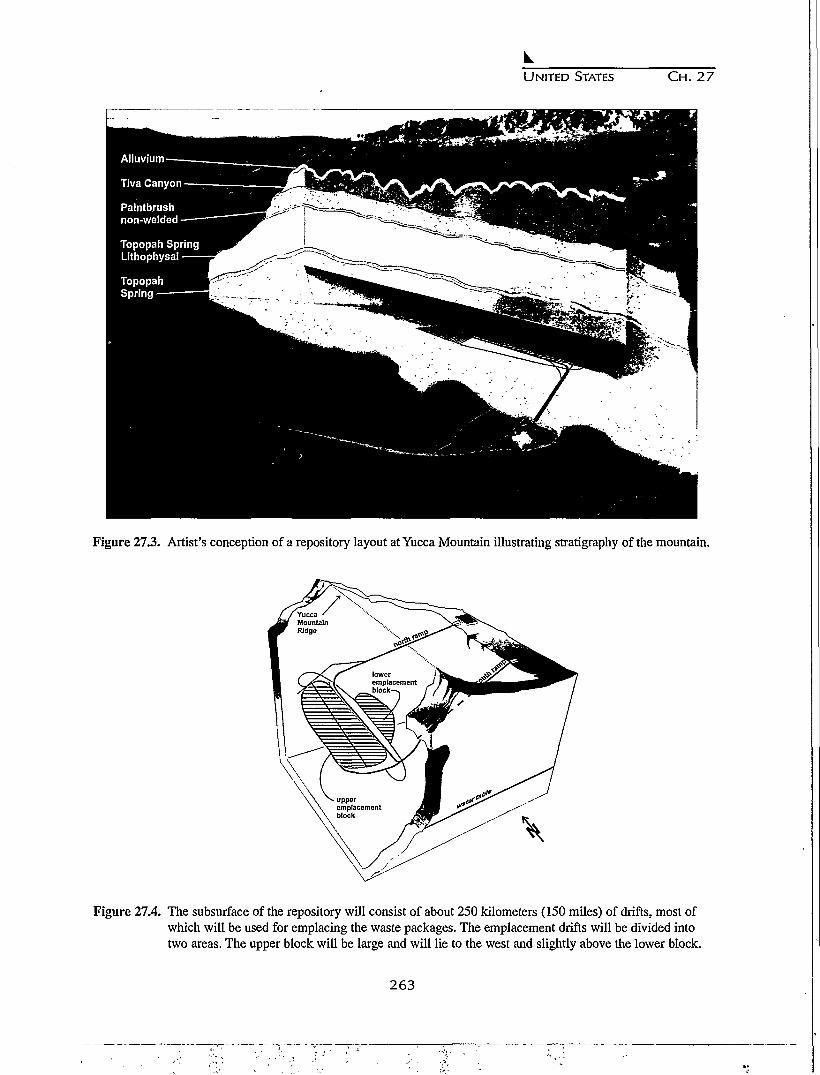
UNITED STATES C H . 27
Figure 27.3. Artist's conception of a repository layout at Yucca Mountain illustrating stratigraphy of the mountain.
Figure 27.4. The subsurface of the repository will consist of about 250 kilometers (150 miles) of drifts, most ofwhich will be used for emplacing the waste packages. The emplacement drifts will be divided intotwo areas. The upper block will be large and will lie to the west and slightly above the lower block.
263
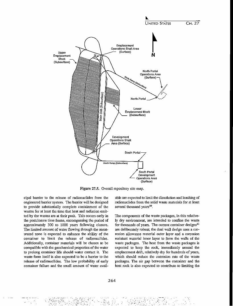
UNITED STATES CH. 27
UpperEmplacement
Block —.(Subsurface) \
EmplacementOperations Shaft Area
(Surface)N
North PortalOperations Area
(Surface)
LowerEmplacement Block
(Subsurface)
DevelopmentOperations ShaftArea (Surface)
South Ramp (Subsurface)
South PortalDevelopment
Operations Area(Surface)
Figure 27.5. Overall repository site map.
cipal barrier to the release of radionuclides from theengineered barrier system. The barrier will be designedto provide substantially complete containment of thewastes for at least the time that heat and radiation emit-ted by the wastes are at their peak. This occurs early inthe postclosure time frame, encompassing the period ofapproximately 300 to 1000 years following closure.The limited amount of water flowing through the unsat-urated zone is expected to enhance the ability of thecontainer to limit the release of radionuclides.Additionally, container materials will be chosen to becompatible with the geochemical properties of the waterto prolong container life should water contact it. Thewaste form itself is also expected to be a barrier to therelease of radionuclides. The low probability of earlycontainer failure and the small amount of water avail-
able are expected to limit the dissolution and leaching ofradionuclides from the solid waste materials for at leastseveral thousand years10.
The components of the waste packages, in this relative-ly dry environment, are intended to confine the wastefor thousands of years. The current container designs11
are deliberately robust; the dual wall design uses a cor-rosion allowance material outer layer and a corrosionresistant material inner layer to form the walls of thewaste packages. The heat from the waste packages isexpected to keep the rock, immediately around theemplacement drift, relatively dry for hundreds of years,which should reduce the corrosion rate of the wastepackages. The air gap between the container and thehost rock is also expected to contribute to limiting the
264

UNITED STATES C H . 27
release of radionuclides. Because percolation rates areexpected to be low, and because most water is expectedto be tightly confined in the rock matrix, little watershould cross this air gap. Limited water movement infractures is possible; however, the amount of water thatcould potentially contact the containers is expected tobe a small fraction of that contained in the rock. As thewaste packages and emplacement drifts eventually cool,water could begin to seep back toward the waste pack-ages, especially along fractures.
After the waste packages eventually corrode and deteri-orate, and the engineered barrier function is degraded,the natural barriers will provide the primary means ofisolation. The various rock layers at Yucca Mountain,due to low water content and movement, are expected toretard the movement of released radioactive material tothe accessible environment. Finally, any radioactivematerial that eventually reached the water table beneaththe repository would be diluted, further reducing thepotential amounts that could reach the environment.
The current repository conceptual design assumes a rel-atively high emplacement density of 83 metric tons ofinitial heavy metal (MTU) per acre. The resultingemplacement scheme divides the subsurface facilitiesinto two sets of waste emplacement drifts calledblocks11. In this concept, the emplacement drifts wouldbe spaced at 22.5 meters and emplacement drifts wouldrange from about 250 meters to about 600 meters inlength. The upper block would cover about 324hectares, and could accommodate about 11,000 wastepackages. The lower block would cover about 69hectares, and could accommodate up to 2,400 addition-al waste packages. A total of about 12,000 waste pack-ages are expected to be emplaced11-12. Approximately90 percent of the radioactive waste will be spent fuel inwaste packages, each containing up to 9 metric tons ofspent fuel. However, it is currently expected that morethan one-fourth of the total number of waste packageswill be high level waste, with each package containingapproximately 2 metric tons of high level wastes.
The physical arrangement in which waste packageswould be placed underground will have an impact onthe environmental conditions in the emplacement drifts.After emplacement, heat will raise the temperature ofthe emplacement drift rock walls. The spacing betweenthe emplacement drifts and the spacing between wastepackages within the emplacement drifts will determinehow hot the emplacement drift environment and sur-rounding rock will become. Conceptual designs have
been developed for fuel assemblies that have beenshipped to the repository in containers (canistered anddefense high-level waste disposal containers) that canbe placed into an overpack for subsequent emplacementfor disposal in the repository. Conceptual designs alsohave been developed for fuel assemblies that arrive in ashipping container (uncanistered) and must be repack-aged for subsequent emplacement for disposal in therepository (Fig. 27.6).
The waste packages would be mounted on rail cars that
uncanistereddisposalcontainer
basket
defense high-levelwaste disposalcontainer
o
Conceptual design characteristics for disposal containers.
Uncanistered
large small
Canistered
large small
DHLW
Capacity (number of fuel assemblies or pour canisters)
PWR
BWR
Canisters
21
44
—
12
24
—
21
40
—
12
24
—
—
4
Dimensions in millimeters
Diameter
Length
1629
(64")
5335
(210")
1298/1265*
(51"/50")
5335
(210")
1802
(71")
5682
(224")
1531
(60")
5647
(222")
1709
(67")
3680
(145")
Weight in kilograms (approximate)
Empty
Loaded
31,000
(34 tons)
47,000
(52 tons)
22,000
(24 tons)
31,000
(34 tons)
31,000
(34 tons)
65,000
(72 tons)
25,000
(28 tons)
47,000
(52 tons)
13,000
(14 tons)
22,000
(24 tons)
PWR - Pressurized Water Reactor BWR - Boiling Water Reactor* larger diameter for PWR, smaller diameter for BWR
Figure 27.6. Conceptual designs address disposal con-tainers for fuel assemblies not in canisters,fuel assemblies in canisters, and pour can-isters.
265

UNITED STATES CH. 27
center, in-drift option off-center, in-drift option
compacted filldrift floor
Figure 27.7. Conceptual design options for emplacement drifts: center in-drift, with a single set of rails for placingthe waste package in the center of the drift; and off-center in-drift, with two sets of rails for placingthe waste package to one side of the drift.
would be placed on rails within the emplacement drift.Once waste packages are placed in an emplacementdrift, no human entry into that emplacement drift wouldbe allowed under normal conditions. Two options, illus-trated in Figure 27.7, are being studied for emplacementof waste packages within the emplacement drifts. Oneoption, center in-drift, involves a single set of rails run-ning down the center of the drift on which the wastepackage rail car unit would be placed. The diameter ofthis emplacement drift would be 5 meters. The otheroption, off center in-drift, would contain two parallelsets of rails. The rail car would be placed on one set ofrails to the side of the drift, and the set on the other sideof the drift would provide remote access along the driftfor inspecting, monitoring and maintaining the drift,emplaced materials, and equipment. The diameter ofthis emplacement drift would be 5.5 meters.
Each combination of drift and package spacing, andwaste package heat output, will result in a differentoverall thermal load. Corresponding temperatures willcause various changes in the repository rock and itswater content, which can affect waste package perfor-mance. Potential changes in rock strength, water con-tent and mineral composition depend primarily on thethermal loading. These changes are being investigatedby both field and laboratory testing and by the use ofcomputer modeling techniques. A repository designgoal to not exceed wall rock temperatures of 200° C wasestablished11. The current conceptual repository designuses a relatively high thermal loading that results in
maximum emplacement drift wall temperatures ofapproximately 155° C at about 40 to 60 years afteremplacement, if no ventilation is supplied to the driftafter emplacement is completed12.
As would be expected, this strategy is sensitive to dis-ruptive processes and events, especially those that couldmodify the dry character of the site, which is central tothe compliance arguments. Of particular importance tothe strategy are climate changes and processes or eventsthat could enhance infiltration. The effects of reposito-ry heating on the conditions of the rock mass are also ofconcern. A high thermal load may drive moisture awayfrom the canisters for significant periods of time.Conversely, the temperature changes could lead topotentially irreversible changes in the hydrologic andgeochemical properties of the zeolites in the rock mass.
Another issue of engineered barrier performance isrelated to the presence in the waste of gaseous radionu-clides such as 14CO2. The natural barriers at YuccaMountain are not likely to be effective in containinggases that could be released through eventual failure ofwaste containers. Early waste package failure couldlead to the release of quantities of 14CO2 that could pos-sibly violate the remanded standard for total curiesreleased, even though there would be no significantassociated health effects. Although the standard hasbeen remanded, it is still used as a standard for compar-ison by the program until a new one is in place Thewaste packages likely could be designed to contain the
266
-• ••.. • • - . - : - •? .

UNITED STATES C H . 2 7
gases, but the lack of true health and safety protectionmakes it difficult to justify the costs.
27.4 RESULTS OF SITE CHARACTERIZATION
COMPLETED TO DATE
The test program described in the Site CharacterizationPlan2 included both surface based and underground testprograms, the latter in a facility developed at the base ofan exploratory shaft. Review comments on that planfrom the Nuclear Regulatory Commission13 and theUnited States Nuclear Waste Technical Review Board14
were addressed15 and, in so doing, the configuration waschanged from shaft access to ramp access. The result-ing facility design incorporated requirements to supporta test program to address data needed to assess the roleof both the engineered barriers and the natural barriers.Heater tests, ranging in scale up to room size, will beconducted over the next several years to investigate cou-pled thermal-mechanical-hydrological-geochemicalprocesses, moisture movement, mechanical effects, andnear field effects. Other underground tests underway orplanned include construction tests, which examine exca-vation methods, measurements of the response ofground support systems, possible emplacement equip-ment tests, seal component tests, seismic tomography,and rock strength tests. Hydrology and transport will bestudied through suites of tests such as large scale per-meability tests, radial borehole permeability (gas andwater) tests, hydrochemistry tests, mapping, diffusiontests, radionuclide transport tests (using non-radioactivetracers) and percolation tests, potentially above, at andbelow the repository horizon. The field experiments arecomplemented by laboratory tests, including, thermal,mechanical, hydrological and rock water interaction.
Observations of the natural system and site data collect-ed since 1978 suggest that the natural system is robust,and that numerical models and calculations will be ableto bound many of the uncertainties for radiological safe-ty evaluations, leading to enhanced confidence in theperformance of the site. No major unexpected condi-tions have been encountered; tunneling and testing areconfirming the hypotheses on site conditions describedin the 1986 Environmental Assessment and the 1988Site Characterization Plan. Recent performance assess-ments10 have led to increased confidence that a YuccaMountain repository would contain and isolate radioac-tive waste and would meet a reasonable EPA standard.Disruptive events, such as volcanism or seismicity, areconsidered unlikely to adversely impact performance.The project recently completed an independent external
expert elicitation on probabilistic volcanic hazards16 thataffirmed the project position on low (order of 10"8 peryear) probability of a volcanic event penetrating therepository. An improved site and engineering data basesupports performance assessment calculations that pro-vide more realistic bounding conditions.
Site hydrologic models17 indicate groundwater flux islikely to be limited and very low at the repository hori-zon, possibly with local exceptions. The results of mod-eling and field investigations support a conclusion thatinfiltration could be diverted laterally away from therepository horizon, owing to the distinctly differenthydrologic properties at the contact between coarse-grained and permeable non-welded tuff, and underlyingand overlying fine-grained and relatively impermeablewelded tuff layers (Fig. 27.3). These hydrologic condi-tions have the potential to buffer the effects of increasedinfiltration that potentially could occur as a result of cli-matic changes. Exploratory studies facility tunnelingprogress has greatly increased the opportunity forunderground observations and confirms constructabilityand geologic characteristics with no observable waterseepage. Also, extensive underground drifting, whichprovides a greater opportunity for observation and sam-pling, has supplanted the originally proposed drillingprogram.
27.5 PLANNED FUTURE WORK
Program scientists and management today believe that areduction in the scope of the characterization programfrom that originally proposed is justifiable and desir-able. This reduced scope is supported both throughincreased understanding gained through progress in thecharacterization program and through realignment oflicensing expectations with the information that can rea-sonably be obtained at different phases of the program18.The current understanding of the importance of the indi-vidual elements of the disposal system is better andmore quantitative than at the time the SiteCharacterization Plan was written. Some of the uncer-tainties identified in the Site Characterization Plan arenow known to be not as important as others.Performance assessments and modeling have identifiedthe most important uncertainties and methods to boundresolution of other uncertainties without executing everyactivity of the extensive characterization program origi-nally described in the Site Characterization Plan. Whathas been learned leaves fewer, but still technicallyimportant, questions to be answered about significantfeatures and processes of the natural geologic, hydro-
267

UNITED STATES CH. 27
logic, and engineered components that would be part ofa potential Yucca Mountain repository.
In addition to new site characterization information andperformance based analyses capable of evaluating totalsystem performance, other developments such as updat-ed repository and waste package conceptual designs,and considerations related to the change from a releasestandard to a dose or risk-based standard, with an as-yetunspecified regulatory time frame, have contributed tothe need to refine the strategy for evaluating waste con-tainment and isolation.
The updated strategy currently being developed main-tains a number of fundamentals of the original strategy.The updated strategy continues to recognize the impor-tant role of the relatively dry conditions at YuccaMountain, which contributed to the site originally beingselected for characterization studies. The updated strat-egy also continues to recognize the geochemical settingprovided by Yucca Mountain as important to determin-ing the rate at which radionuclides may be released intothe environment in the future, when containment by thewaste packages is eventually lost.
The current program is structured around a series ofmajor products leading to an eventual license applica-tion. One of the most visible major products in the nearterm is a Viability Assessment to be completed in 1998.The Viability Assessment has four components:
1. Design of critical parts of the repository, waste pack-ages, and engineered barrier system;
2. Performance assessment that incorporates currentknowledge of natural features, processes, andresponses at Yucca Mountain, and that evaluates thelong term performance of the total natural and engi-neered system;
3. Total System Life Cycle Cost estimate for the con-struction, operation, and closure of the repository;and
4. Licensing Plan to lay out tests, design activities, orother actions needed to complete an initial licenseapplication for submittal to the United States NuclearRegulatory Commission.
The purpose of the Viability Assessment is to providepolicy makers with an integrated view of a repositorysystem, its estimated performance capabilities, and theassociated cost and schedule. If policy makers acceptand endorse that assessment, it is anticipated thatresources will be committed to ensure continued
progress toward the license application.
Current project planning also reflects the need to com-plete field studies and analyses to reduce uncertaintyand enhance understanding of system performance tosupport the assessment of system safety needed for thelicense application. The larger technical questions iden-tified in recent total system performance assessments10
as key to evaluating repository and waste package per-formance are related to the following attributes of thesystem:
1. Rate of water seepage into the repository;2. Integrity of waste packages (containment);3. Rate of release of radionuclides from waste in the
breached waste packages;4. Radionuclide transport through engineered barriers
and natural barriers; and5. Dilution in the groundwater below the repository.
The refined waste isolation and containment strategywill also address what approach will be taken to gather-ing data and developing models to make better predic-tions of these attributes over time. As the repositorygenerates heat and then gradually returns to ambienttemperatures, it is expected that at least the first four ofthese attributes will be affected, changing their relativeimportance to system performance as a function of time.
In the absence of a definitive compliance standard forgeologic disposal, the United States Department ofEnergy is defining waste containment and isolation forpurposes of conducting the viability assessment in sucha way as to be independent of the specific compliancemeasures that eventually will be promulgated19. Wastecontainment has been defined as: the near-completecontainment of radionuclides by waste packages for sev-eral thousands of years. Isolation has been defined witha system-level safety goal as: an acceptable dose to amember of the public living near the site. Quantitativedose modeling results will be used to evaluate compli-ance with applicable standards; more attention will bepaid to evaluating potential doses for the first ten thou-sand years. However, calculations will be carried outover longer times in order to provide qualitative insightinto peak dose potential, and to support system enhance-ment studies.
The United States Department of Energy recognizesthere are issues which cannot be completely resolved inthe 1998 Viability Assessment. Scientific and engineer-ing studies will continue to be conducted to guide con-
268
UNITED STATES CH. 27
firmation of or revision to the basis for modeling per-formance of the repository system. There is an expecta-tion that additional data and analyses will be required tosupport a license application. It also recognizes that, ifa license is granted, confirmatory technical work willcontinue beyond the time of license application into theconstruction and operational phases of the repository.
27.6 CONCLUSIONS
Following amendment in 1987 of the legislation autho-rizing characterization of sites for a repository, theUnited States' high-level waste program focused onYucca Mountain in the southwestern United States asthe single site under consideration. The attributes ofYucca Mountain that made it technically attractive near-ly twenty years ago continue to be the technical under-pinnings of the strategy for long term waste containmentand isolation. Significant progress has been made in thecharacterization of Yucca Mountain as a potential sitefor a mined geologic repository. Conditions encoun-tered in the exploratory studies facility tunnel at reposi-tory depth are consistent with expectations of such afacility constructed in the unsaturated zone. Total sys-tem performance assessments of the long term behaviorof a repository at Yucca Mountain continue to mature,and have provided significant guidance in helping definepriorities in the test programs and design solutions forthe engineered barriers.
The technical strengths of the Yucca Mountain sitedepend on limited water available to contact the wastesand a corresponding high potential for isolation of thewastes. Today, the United States regulatory approach tolong term compliance is uncertain. While the UnitedStates Nuclear Regulatory Commission regulations arein place, the United States Environmental ProtectionAgency standards for disposal safety are remanded.Actions underway to develop a new standard for dispos-al safety are reopening issues fundamental to the struc-ture of the regulatory approach.
The United States high-level waste program regulationswere, in the past, based on a relatively long time frameof regulatory interest, 10,000 years, and assessed com-pliance against limits on total system releases at anaccessible environment, located five kilometers from therepository. The National Academy of Sciences9 recom-mendation that the United States adopt a dose basedstandard for postclosure compliance for a repository hasraised issues relative to the regulatory time frame, doseand risk, the definition of the reference biosphere,
human intrusion and the quantitative treatment of natur-al processes and events. Deliberation of these issues isexpected to be intense and time consuming, and funda-mental re-evaluation of the United States approach tolong term compliance should not be unexpected.
Technically, the Yucca Mountain site remains attractivebecause of its great potential to isolate wastes.However, there are significant concerns about the abili-ty to bring to closure a regulatory proceeding that couldhave to deal with what are unprecedented time frames inthe context of regulation. The potential for a geologicdisposal standard that could introduce a need to rely ondilution in a closed hydrologic basin to meet a dosebased standard takes the United States high-level wasteprogram full circle back to the promulgation of theUnited States Environmental Protection Agency stan-dards for geologic disposal. In those proceedings, adose based standard was considered to be an inappro-priate policy that could increase overall populationexposures by encouraging disposal methods that wouldenhance dilution of any radionuclides released5.
The extent to which the Yucca Mountain site eventuallycan be shown to be in compliance with a regulation thatis evolving amid questions about the very nature of theregulatory structure that has been the basis for selectionof the site, and assessment of its performance for nearlytwenty years, is a significant concern. This reassessmentis occurring even as the geologic and engineering disci-plines are beginning to evolve data sets that are unprece-dented in depth, breadth and specificity for evaluatingthe Yucca Mountain site for its waste isolation potential.
REFERENCES
1 United States Congress. Nuclear Waste PolicyAmendments Act of 1987. Public Law 100-203,100th Congress, December 22,1987.
2. Unites States Department of Energy. SiteCharacterization Plan. Yucca Mountain Site, NevadaResearch and Development Area, Nevada. Office ofCivilian Radioactive Waste Management, ReportDOE/RW-0199, December 1988.
3. United States Congress. Waste Isolation Pilot PlantLand Withdrawal Act. Public Law 102-579, 102dCongress, October 30, 1992.
4. United States Congress. Nuclear Waste Policy Act of
2 6 9

UNITED STATES CH. 27
1982. Public Law 97-425, 97th Congress, January 7,1983.
5. United States Environmental Protection Agency.Environmental Standards for the Management andDisposal of Spent Nuclear Fuel, High-level andTransuranic Radioactive Wastes. (40 CFR Part 191).Federal Register, vol. 50, no. 182, Sept. 19,1985.
6. United States Nuclear Regulatory Commission.Disposal of High-level Radioactive Wastes inGeologic Repositories. Code of Federal Regulations,Title 10, Part 60.
7. United States Congress. Energy Policy Act of 1992.Public Law 102-486, October 24,1992.
8. National Research Council, Board on RadioactiveWaste Management, Waste Isolation Systems Panel,United States National Academy of Sciences. AStudy of the Isolation System for Geologic Disposalof Radioactive Wastes. National Academy Press,Washington, D.C. 1983.
9. National Research Council. Technical Bases forYucca Mountain Standards. Committee on TechnicalBases for Yucca Mountain Standards, Board onRadioactive Waste Management, United StatesNational Academy of Sciences. National AcademyPress, Washington, D.C., 1995.
lO.Civilian Radioactive Waste Management SystemManagement and Operating Contractor. Total SystemPerformance Assessment - 1995: An Evaluation ofthe Potential Yucca Mountain Repository.BOOOOOOOO-01717-2200-00136, Rev. 01, November1995.
11.Civilian Radioactive Waste Management SystemManagement and Operating Contractor. MinedGeologic Disposal System Advanced ConceptualDesign Report. B0000000O-O1717057O5-O002,.
Rev. 00, March 1996.
12.McKenzie, Daniel.G., DI, Kalyan K Bhattacharyya,and Alden Segrest. Conceptual Subsurface FacilityDesign for a High Level Nuclear Waste Repository atYucca Mountain. 37th Annual Meeting of theInstitute of Nuclear Materials Management. July1996.
13.United States Nuclear Regulatory Commission.NRC Staff Site Characterization Analysis of theDepartment of Energy's Site Characterization Plan,Yucca Mountain Site, Nevada. NUREG-1347.August 1989.
14.United States Nuclear Waste Technical ReviewBoard. First Report to the United States. Congressand the United States Secretary of Energy, March1990.
15.Dennis, A. W. (editor). Exploratory Studies FacilityAlternatives Study: Final Report. Sandia NationalLaboratories, SAND91-0025. September 1991.
16.Geomatrix Consultants, Probabilistic VolcanicHazard Analysis for Yucca Mountain, Nevada, DraftReport, Volumes I, JJ, March 1996.
17.Wittwer, C , Chen, G., Bodvarsson, G.S., Chornack,M., Flint A., Flint L., Kwickless, E., and Spengler,R.. Preliminary Development of the LBL/USGSThree Dimensional Site Scale Model of YuccaMountain, Nevada. Lawrence Berkeley NationalLaboratory Report. LBL-37356/UC-814. June 1995.
18.United States Department of Energy. CivilianRadioactive Waste Management Program Plan.DOE/RW-0458. December 1994.
19.United States Department of Energy. CivilianRadioactive Waste Management Program Plan.Draft Revision 1. DOE/RW-0458. May 1996.
270