geologic reconnaissance melrose heights oceanside, california
TRANSCRIPT

GEOLOGIC RECONNAISSANCE
MELROSE HEIGHTS OCEANSIDE, CALIFORNIA
PREPARED FOR
M&O PARTNERS, LP RANCHO SANTA FE, CALIFORNIA
JUNE 5, 2012 PROJECT NO. 06904-32-02

GROCON INCORPORATED
GEOTECHNICAL • ENVIRONMENTAL MATERIALSO
6960 Flanders Drive • San Diego, California 92121-2974 • Telephone 858.558.6900 • Fax 858.558.6159
Project No. 06904-32-02 June 5, 2012 M&O Partners, LP 5505 Cancha de Golf Rancho Santa Fe, California 92091 Attention: Mr. Nicholas B. Biancamano Subject: GEOLOGIC RECONNAISSANCE MELROSE HEIGHTS OCEANSIDE, CALIFORNIA Dear Mr. Biancamano:
In accordance with your request and our proposal LG-12045 dated February 7, 2012, we have performed a geologic reconnaissance on the subject properties. The study included a compilation and summary of our previous work performed on the site to evaluate the soil and geologic conditions and potential geologic hazards may be present. The primary focus of this recent study was to identify geotechnical constraints that could potentially impact project development as presently proposed. It is our opinion that the site can be developed as planned provided our preliminary recommendations are followed. The presence of an ancient landslide deposit and remedial grading of surficial deposits will be the primary considerations during site development. In this regard, a future geotechnical study will be necessary once the grading plans are developed to evaluate slope stability and to provide specific geotechnical recommendations for the project. If you have any questions regarding this report, or if we may be of further service, please contact the undersigned at your convenience. Very truly yours, GEOCON INCORPORATED Troy K. Reist CEG 2408
Trevor Myers RCE 63773
David B. Evans CEG 1860
TKR:TEM:DBE:dmc (6) Addressee

TABLE OF CONTENTS
1. PURPOSE AND SCOPE ...................................................................................................................... 1
2. SITE AND PROJECT DESCRIPTION ................................................................................................ 1
3. SOIL AND GEOLOGIC CONDITIONS ............................................................................................. 2 3.1 Compacted Fill (Qcf) .................................................................................................................. 2 3.2 Undocumented Fill (Qudf) ......................................................................................................... 2 3.3 Topsoil (Unmapped) ................................................................................................................... 3 3.4 Alluvium (Qal) ........................................................................................................................... 3 3.5 Landslide Deposit (Qls) .............................................................................................................. 3 3.6 Terrace Deposits (Qt) ................................................................................................................. 3 3.7 Santiago Formation (Tsa) ........................................................................................................... 3 3.8 Granitic Rock (Kb) ..................................................................................................................... 4
4. GEOLOGIC STRUCTURE .................................................................................................................. 5
5. GROUNDWATER ............................................................................................................................... 5
6. GEOLOGIC HAZARDS ...................................................................................................................... 5 6.1 Faulting and Seismicity .............................................................................................................. 5 6.2 Liquefaction and Seismically Induced Settlement ...................................................................... 7 6.3 Ancient Landslides ..................................................................................................................... 8
7. SUMMARY, CONCLUSIONS, AND RECOMMENDATIONS ........................................................ 9 7.1 General ........................................................................................................................................ 9 7.2 Foundations .............................................................................................................................. 10 7.3 Preliminary Grading Recommendations ................................................................................... 10 7.4 Drainage and Maintenance ....................................................................................................... 11 7.5 Grading and Foundation Plan Review ...................................................................................... 11
LIMITATIONS AND UNIFORMITY OF CONDITIONS MAPS AND ILLUSTRATIONS Figure 1, Vicinity Map Figure 2, Geologic Map (Map Pocket) APPENDIX A PREVIOUS EXPLORATORY AND LABORATORY DATA (prepared by Geocon Incorporated) APPENDIX B RECOMMENDED GRADING SPECIFICATIONS LIST OF REFERENCES

Project No. 06904-32-02 - 1 - June 5, 2012
GEOLOGIC RECONNAISSANCE
1. PURPOSE AND SCOPE
This report presents the results of a geologic reconnaissance of the proposed Melrose Heights project located in Oceanside, California (see Vicinity Map, Figure 1). The study was intended to identify geotechnical constraints in the areas of planned development, if any, and provide preliminary recommendations for site grading based on a reconnaissance level investigation.
Previous geotechnical studies were performed on the property in 2000 and 2002 by Geocon Incorporated that extended beyond the limits of the proposed project. The pertinent exploratory and laboratory information from the past studies has been included in Appendix A of this report. This information is also shown on the Geologic Map, Figure 2.
The scope of our study included a review of readily available published geologic literature pertinent to the project (see List of References), performing a field reconnaissance that consisted of geologic mapping across the site, reviewing stereoscopic aerial photographs of the property, and preparing this report summarizing our findings. Once the final grading plans have been prepared, a geotechnical investigation will be required to evaluate slope stability and provide specific geotechnical recommendations with respect to the proposed development.
The exhibit used as our Geologic Map consists of an AutoCAD file consisting of site topography provided by T&B Planning. The map also depicts the configuration of the property, proposed sheet grading, mapped geologic contacts, and the approximate locations of the previous exploratory boring and trench excavations. The conclusions and recommendations presented herein are based on an analysis of the data reviewed as part of this study and our experience with similar soil and geologic conditions.
2. SITE AND PROJECT DESCRIPTION
The approximately 39-acre project is located on the eastern boundary of Oceanside, California. Specifically, the site is located within an undeveloped area to the north of Oceanside Boulevard/Bobier Drive between Sports Park Way and Catalina Circle.
It is our understanding that the site will be developed to create three separate high-density residential developments (Areas A, B and C) with up to 936 dwelling units, a park site, and associated roadway and infrastructure improvements. Several retaining walls up to approximately 30 feet high are also proposed along the perimeter of the development areas. Grading will consist of maximum cut and fills on the order of approximately 50 feet. The cut and fill slopes are designed at 2:1 (horizontal:vertical) or flatter.

Project No. 06904-32-02 - 2 - June 5, 2012
Topographically, the project site consists of gentle to moderate sloping terrain that descends gradually to the north. Elevations within the proposed development range from approximately 450 feet Mean Sea Level (MSL) in the southeast portion of the property near Sports Park Way to approximately 305 feet MSL within the drainage area in the northwestern corner of the proposed park area. Vegetation consists of natural grasses and chaparral along with wetland and riparian habitats within the main drainages.
The locations and descriptions of the site and proposed improvements are based on site reconnaissance, a review of concept maps, and our general understanding of the project as presently proposed. If project details vary significantly from those described above, or if the agency requirements differ than those anticipated, Geocon Incorporated should be retained to update and/or modify this report accordingly.
3. SOIL AND GEOLOGIC CONDITIONS
Five surficial soil types and three geologic formations have been identified across the site. The surficial deposits consist of compacted fill, undocumented fill, topsoil, alluvium, and a landslide deposit. The formational units include Quaternary Terrace Deposits, Eocene-age Santiago Formation, and Cretaceous-age Bonsall Tonalite (Granitic Rock). Each of the surficial soil types and geologic units encountered is described below in order of increasing age. The approximate extent of the deposits, excluding topsoil, is shown on the Geologic Map, Figure 2.
3.1 Compacted Fill (Qcf)
Compacted fill associated with the grading of Sports Park Way are present along the eastern portion of the site. Testing and observation services were provided by Geocon Incorporated and information pertaining to the grading is included in Reference No. 7. Typical benching into the existing embankment will be required prior to additional fill placement, if any.
3.2 Undocumented Fill (Qudf)
Undocumented fill deposits have been identified and mapped within a large portion of Area A and the southern portions of Area B. These materials have a maximum thickness of 21 feet (LB-1), are generally loose/soft, and will require complete removal and compaction during the remedial phase of grading.
Laboratory test results on samples taken from boring LB-1 indicate that undocumented fill has an Expansion Index in some areas ranging from 15 to 117 and is classified as having a “very low” to “high” expansion potential as defined by 2010 California Building Code (CBC) Section 1803.5.3.
Project No. 06904-32-02 - 3 - June 5, 2012
3.3 Topsoil (Unmapped)
Topsoils blanket the majority of the site and vary in thickness from approximately 1 to 4½ feet. The topsoils are characterized as soft to stiff/loose, sandy clays to clayey sands. Topsoil deposits are considered unsuitable in their present condition and will require remedial grading in areas planned to receive structural fill and/or settlement-sensitive structures. The clayey topsoils typically possess a medium to high expansion potential and should be placed in deeper fill areas.
3.4 Alluvium (Qal)
Alluvial soils were mapped within drainage channels in several locations of the site. These deposits where encountered, consist of relatively soft/loose, sandy clays to silty sands. The alluvial deposits are compressible and will require remedial grading in areas of planned development.
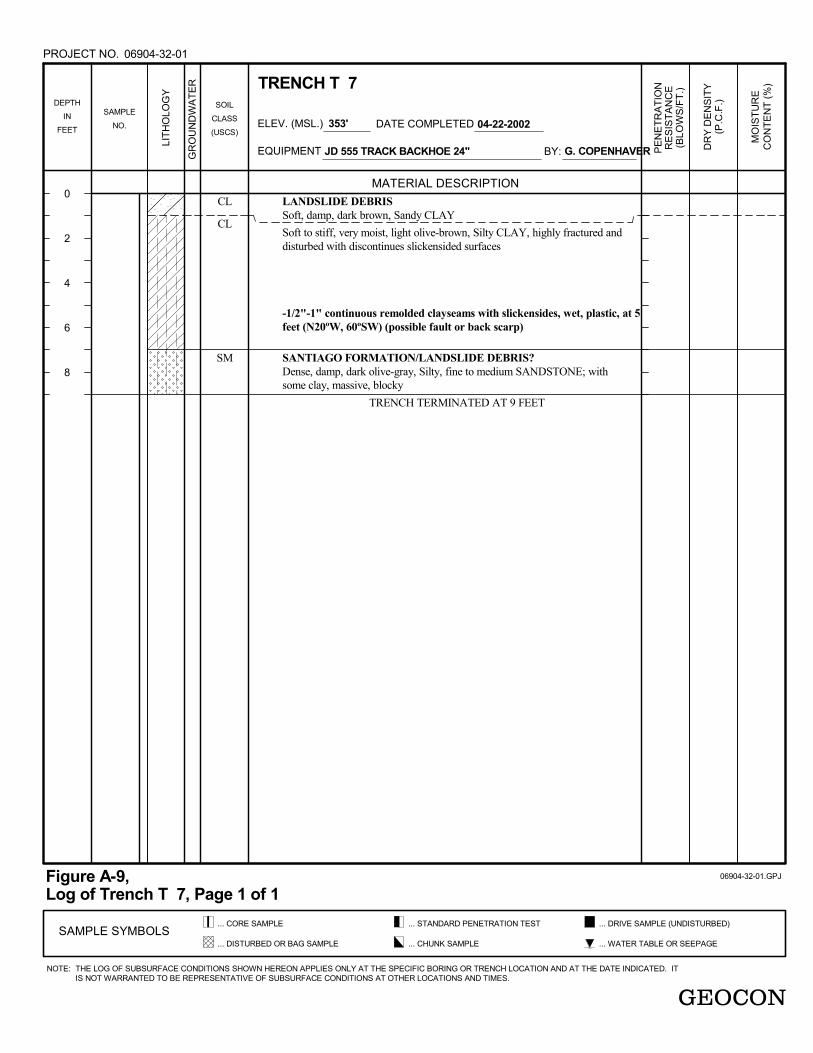
3.5 Landslide Deposit (Qls)
An ancient landslide deposit was identified within the western boundary of Area C and southeastern portion of Area B as shown on the Geologic Map. This deposit appears to have occurred within the gentle to moderately steep slopes of the Santiago Formation. Characteristic landslide morphology of bulging, hummocky and distorted topography was observed during our mapping.
The maximum thickness of landslide debris encountered was 34½ feet (LB-2). This material will likely require removal and compaction prior to placement of fills and/or structural improvements. Since the proposed development is planned on only portions of this deposit, identifying the geometry of the slide will be an important consideration during future studies. It is possible that remedial grading, or other geotechnical stabilization techniques, will be necessary beyond the development limits to provide an acceptable factor of safety with respect to project slope stability.
3.6 Terrace Deposits (Qt)
A terrace deposit described as very dense to medium dense/stiff, reddish to yellowish brown, clayey sand to sandy clay was encountered within Trench Nos. T-9, T-11, T-13, T-14, T-17, T-18, and T-36. This deposit varied in thickness from 5-feet, to over 10.5-feet, and generally appears to possess suitable bearing characteristics in its present state. Some areas, however, may require evaluation in this regard during future studies. (e.g. in the vicinity of Trench T-17).
3.7 Santiago Formation (Tsa)
The Eocene-age Santiago Formation was deposited nonconformably on the Bonsall Tonalite and consists of relatively flat-lying claystone, siltstone, and sandstone units. Weak, waxy claystone and

Project No. 06904-32-02 - 4 - June 5, 2012
thinly laminated siltstone/claystone and sandstone are present within this unit and have been found at various elevations throughout the site.
With the exception of the sandier portions of the Santiago Formation, materials derived from this unit typically possess a medium to high expansion potential with a moderate to low shear strength. In addition, the Santiago Formation typically has a high to moderate potential to transmit seepage along impervious layers. As evidenced in Boring LB-1, the Santiago Formation can exhibit cemented zones that can result in excavation difficulty during grading and construction of site improvements (e.g., underground utility lines and building foundations).
Bedding-plane shears (i.e. remolded clay seams) are relatively common within the Santiago Formation and are significant in that they represent inherent planes of weakness within the formation. These shear zones are typically parallel to the bedding and are characterized by thin seams of very soft, moist to wet, remolded plastic clay. The previous study encountered several bedding-plane shears within the Santiago Formation. Where these features are anticipated to “daylight” in or below proposed cut slopes, stabilization measures will be required.
3.8 Granitic Rock (Kb)
Cretaceous-age Bonsall Tonalite (granitic rock) of the Southern California Batholith was encountered within the northern portion of the project. The rock materials exhibited a variable weathering pattern ranging from completely weathered, decomposed granite to outcrops of fresh, extremely strong, hard rock that may require blasting to excavate. The recent grading work for the adjacent Vista Park Site required some blasting to remove core stones and rock material.
Granitic units generally exhibit adequate bearing and slope stability characteristics and cut slopes excavated at an inclination of 2:1 (horizontal:vertical) should be stable to the proposed heights if free of adversely oriented joints or fractures.
The soils derived from excavations within the decomposed granitic rock are anticipated to consist of low-expansive, silty, medium- to coarse-grained sands and should provide suitable foundation support in either a natural or properly compacted condition. It should be anticipated that excavations within the granitic rock will generate boulders and oversize materials (rocks greater than 12 inches in length) that will require special handling and placement. A future rippability study should be considered in the areas where excavations are planned within the granitic rock.

Project No. 06904-32-02 - 5 - June 5, 2012
4. GEOLOGIC STRUCTURE
Bedding within the Santiago Formation is nearly horizontal or gently dipping within the site limits. Based on topographic interpretation and the exploratory excavations, the Santiago Formation/Bonsall Tonalite contact is generally irregular and dips to the north.
5. GROUNDWATER
Perched groundwater or seepage was encountered within Boring LB-2 and Trench T-5 and was observed at the surface within the central drainage course. The groundwater is presumed to be associated with rainwater along the natural watershed or irrigation form nearby sources. Moderate to heavy seepage conditions were also encountered in the bedrock units and ancient landslide deposits on the adjacent properties.
Subdrains will be necessary to intercept and convey seepage migrating along impervious strata. In particular, subdrains will be required in main drainages, along buttress/stability fill excavations (if required), and possibly where impervious layers daylight near the ultimate graded surface. The approximate locations of the canyon subdrains have been shown on Figure 2.
The existing perched groundwater levels can be expected to fluctuate seasonally and may affect remedial grading. In this regard, remedial grading may encounter wet soils and excavation and compaction difficulty, particularly if grading is planned during the winter months. It should also be noted that areas where perched water or seepage was not encountered may exhibit groundwater during rainy periods.
6. GEOLOGIC HAZARDS
6.1 Faulting and Seismicity
Based on our reconnaissance and a review of published geologic maps and reports, the site is not located on any known “active,” “potentially active” or “inactive” fault traces as defined by the California Geological Survey (CGS).
The Newport-Inglewood Fault and Rose Canyon Fault Zone, located approximately 12 and 13 miles west of the site, respectively, are the closest known active faults. The CGS considers a fault seismically active when evidence suggests seismic activity within roughly the last 11,000 years. The CGS has included portions of the Rose Canyon Fault zone within an Alquist-Priolo Earthquake Fault Zone. Based upon a review of available geologic data and published reports, the site is not located within a State of California Earthquake Fault Zone.

Project No. 06904-32-02 - 6 - June 5, 2012
According to the computer program EZ-FRISK (Version 7.62), 11 known active faults are located within a search radius of 50 miles from the property. The nearest known active faults are the Newport-Inglewood and Rose Canyon Faults, located approximately 11 and 12 miles west of the site, respectively, and are the dominant sources of potential ground motion. Earthquakes that might occur on the Newport-Inglewood or Rose Canyon Fault Zones or other faults within the southern California and northern Baja California area are potential generators of significant ground motion at the site. The estimated deterministic maximum earthquake magnitude and peak ground acceleration for the Newport Inglwood Fault are 7.5 and 0.26g, respectively. Table 6.1.1 lists the estimated maximum earthquake magnitude and peak ground acceleration for the most dominant faults in relationship to the site location. We calculated peak ground acceleration (PGA) using Boore-Atkinson (2008) NGA USGS2008, Campbell-Bozorgnia (2008) NGA USGS, and Chiou-Youngs (2008) NGA acceleration-attenuation relationships.
TABLE 6.1.1 DETERMINISTIC SPECTRA SITE PARAMETERS
Fault Name Distance from Site
(miles)
Maximum Earthquake Magnitude
(Mw)
Peak Ground Acceleration
Boore-Atkinson 2008 (g)
Campbell-Bozorgnia 2008 (g)
Chiou-Youngs 2008 (g)
Newport-Inglewood 11 7.5 0.26 0.21 0.26
Rose Canyon 12 6.9 0.21 0.18 0.19 Elsinore 17 7.85 0.24 0.17 0.23
Coronado Bank 27 7.4 0.16 0.11 0.12 Palos Verdes Connected 27 7.7 0.18 0.12 0.15
San Joaquin Hills 35 7.1 0.12 0.10 0.09 Palos Verdes 38 7.3 0.12 0.08 0.08
Earthquake Valley 39 6.8 0.10 0.06 0.06 San Jacinto 41 7.88 0.14 0.09 0.12
Chino 45 6.8 0.08 0.06 0.05
We used the computer program EZ-FRISK to perform a probabilistic seismic hazard analysis. The computer program EZ-FRISK operates under the assumption that the occurrence rate of earthquakes on each mappable Quaternary fault is proportional to the faults slip rate. The program accounts for fault rupture length as a function of earthquake magnitude, and site acceleration estimates are made using the earthquake magnitude and distance from the site to the rupture zone. The program also accounts for uncertainty in each of following: (1) earthquake magnitude, (2) rupture length for a given magnitude, (3) location of the rupture zone, (4) maximum possible magnitude of a given earthquake, and (5) acceleration at the site from a given earthquake along each fault. By calculating

Project No. 06904-32-02 - 7 - June 5, 2012
the expected accelerations from considered earthquake sources, the program calculates the total average annual expected number of occurrences of site acceleration greater than a specified value. We utilized acceleration-attenuation relationships suggested by Boore-Atkinson (2008) NGA USGS, Campbell-Bozorgnia (2008) NGA USGS, and Chiou-Youngs (2008) in the analysis. Table 6.1.2 presents the site-specific probabilistic seismic hazard parameters including acceleration-attenuation relationships and the probability of exceedence.
TABLE 6.1.2 PROBABILISTIC SEISMIC HAZARD PARAMETERS
Probability of Exceedence Peak Ground Acceleration
Boore-Atkinson, 2007 (g)
Campbell-Bozorgnia, 2008 (g)
Chiou-Youngs, 2008 (g)
2% in a 50 Year Period 0.51 0.40 0.46 5% in a 50 Year Period 0.39 0.30 0.34
10% in a 50 Year Period 0.31 0.25 0.26
The California Geologic Survey (CGS) has a program that calculates the ground motion for a 10 percent of probability of exceedence in 50 years based on an average of several attenuation relationships. Table 6.1.3 presents the calculated results from the Probabilistic Seismic Hazards Mapping Ground Motion Page from the CGS website.
TABLE 6.1.3 PROBABILISTIC SITE PARAMETERS FOR SELECTED FAULTS
CALIFORNIA GEOLOGIC SURVEY
Calculated Acceleration (g) Firm Rock
Calculated Acceleration (g) Soft Rock
Calculated Acceleration (g) Alluvium
0.26 0.28 0.32
While listing peak accelerations is useful for comparison of potential effects of fault activity in a region, other considerations are important in seismic design, including the frequency and duration of motion and the soil conditions underlying the site.
6.2 Liquefaction and Seismically Induced Settlement
Liquefaction typically occurs when a site is located in a zone with seismic activity, onsite soil is cohesionless, groundwater is encountered within 50 feet of the surface, and soil relative densities are less than about 70%. If all four previous criteria are met, a seismic event could result in a rapid pore-water pressure increase from the earthquake-generated ground accelerations.

Project No. 06904-32-02 - 8 - June 5, 2012
Due to the relatively high density and grain-size distribution characteristics of the fill, and formation materials at the site, and the absence of a permanent water table in development areas, the risk of seismically induced soil liquefaction adversely impacting the proposed development is considered very low.
6.3 Ancient Landslides
The landslide deposit identified within the site should be mitigated using generally accepted remedial grading techniques. Depending on the geometry of the slide, and possible constraints of grading in the open space, other geotechnical mitigation techniques may be provided to achieve an acceptable factor of safety with respect to project slope stability.

Project No. 06904-32-02 - 9 - June 5, 2012
7. SUMMARY, CONCLUSIONS, AND RECOMMENDATIONS
7.1 General
7.1.1 No soil or geologic conditions were observed during the reconnaissance, or previous studies, that would preclude development of the project as presently planned. It should be noted, however, that the presence of an ancient landslide deposit, partially within the limits of proposed development, may require remedial grading beyond the project limits, or other geotechnical stabilization techniques, to provide an acceptable factor of safety with regard to slope stability. Preliminary grading recommendations presented herein are for planning purposes only. Detailed grading recommendations should be provided in future geotechnical studies based upon site specific information obtained from field subsurface studies.
7.1.2 The site is underlain by surficial units that include undocumented fill soils, compacted fill soils, topsoil, alluvium, and landslide deposits. With the exception of the compacted fill, these materials are unsuitable in their present condition for support of fill and/or structural loads and will require remedial grading. Additional evaluation of the upper portions of the Terrace Deposits may be necessary to determine its suitability to support structural loads.
7.1.3 Bedding plane shears and weak claystones identified in the exploratory borings and trenches may require stabilization measures if they are exposed in proposed slope excavations or never finish grade. Additional subsurface investigation, laboratory testing, and slope stability analyses, will be required to evaluate the existing and proposed grading with respect to these features.
7.1.4 A wall design engineer should be consulted to evaluate the proposed retaining walls for the project. Mechanically Stabilized Earth (MSE) systems may not be feasible in areas of the project, especially along the margins of the “biologically sensitive area” and existing roadways (i.e. Bobier Drive and Melrose Drive). Other retaining systems such as “soil nail” or “solider pile” wall may be necessary where the backcuts may be restricted by existing improvements.
7.1.5 An update geotechnical investigation will be required to provide specific design parameters for the project once the grading plans have been developed. The investigation should include subsurface exploration and laboratory testing to aid in the preparation of slope stability analyses and recommendations for remedial grading (e.g. slope stability fills, wall design parameters). A rippability study to evaluate proposed cut areas where granitic rock is exposed is also recommended.

Project No. 06904-32-02 - 10 - June 5, 2012
7.2 Foundations
7.2.1 The proposed structures can be supported on a conventional shallow foundation system founded entirely in compacted fill or formational materials. Specific design recommendations will be provided in a forthcoming geotechnical investigation.
7.3 Preliminary Grading Recommendations
7.3.1 All grading should be performed in accordance with the Recommended Grading Specifications contained in Appendix B and the applicable governing agencies. Where the recommendations of Appendix B conflict with this report, the recommendations of this report should take precedence.
7.3.2 Prior to commencing grading, a preconstruction conference should be held at the site with the owner or developer, grading contractor, civil engineer, and geotechnical engineer in attendance. Special soil handling and the grading plans can be discussed at that time.
7.3.3 Site preparation should begin with the removal of all deleterious material and vegetation. The depth of removal should be such that material exposed in cut areas or soil to be used as fill is relatively free of organic matter. Material generated during stripping and site demolition should be exported from the site.
7.3.4 All potentially compressible surficial soil (undocumented fill soil, topsoil, alluvium, colluvium, landslide deposits, and terrace deposits) within areas of planned grading should be removed to firm formational material prior to placing fill. Overexcavation below proposed finish grade in the cut of Area A will be necessary to remove and compact the undocumented fill and topsoil. The actual extent of unsuitable soil removals should be determined in the field. Overly wet, surficial materials, if encountered, will require drying or mixing with drier soils to facilitate proper compaction.
7.3.5 The site should be brought to final subgrade elevations with structural fill compacted in layers. In general, existing soil is suitable for re-use as fill if free from vegetation, debris and other deleterious material. Layers of fill should be no thicker than will allow for adequate bonding and compaction. All fill, including backfill and scarified ground surfaces, should be compacted to a dry density of at least 90 percent of the laboratory maximum dry density near or slightly above optimum moisture content, as determined in accordance with ASTM Test Procedure D 1557. Fill materials below optimum moisture content may require additional moisture conditioning prior to placing additional fill.

Project No. 06904-32-02 - 11 - June 5, 2012
7.3.6 To reduce the potential for differential settlement and to facilitate the excavation of footings, it is recommended that cut lots that expose cemented concretionary zones and the cut portion of cut-fill transition pads be undercut at least 3 feet and replaced with compacted fill. The bottom of the undercut portion should be sloped at 1 percent toward the fill portion to facilitate drainage of future subsurface water.
7.3.7 Where practical, the upper 3 feet of all building pads (cut and fill) should consist of “very low” to “low” expansive soils. This will require undercutting cut pads where “medium or greater” expansive soils are exposed at finish grade. The more highly expansive fill soils should be placed in deeper fill areas.
7.4 Drainage and Maintenance
7.4.1 Good drainage is imperative to reduce the potential for differential soil movement, erosion, and subsurface seepage. Positive measures should be taken to properly finish grade the building pads after the structures and other improvements are in place, so that the drainage water from the lots and adjacent properties are directed off the lots and to the street away from foundations and the top of the slopes. Experience has shown that even with these provisions, a shallow groundwater or subsurface water condition can and may develop in areas where no such water conditions existed prior to the site development; this is particularly true where a substantial increase in surface water infiltration results from an increase in landscape irrigation.
7.5 Grading and Foundation Plan Review
7.5.1 Grading and foundation plans for the site should be reviewed to determine if the plans have been prepared in substantial conformance with the recommendations contained within this report.
Project No. 06904-32-02 June 5, 2012
LIMITATIONS AND UNIFORMITY OF CONDITIONS
1. The firm that performed the geotechnical investigation for the project should be retained to provide testing and observation services during construction to provide continuity of geotechnical interpretation and to check that the recommendations presented for geotechnical aspects of site development are incorporated during site grading, construction of improvements, and excavation of foundations. If another geotechnical firm is selected to perform the testing and observation services during construction operations, that firm should prepare a letter indicating their intent to assume the responsibilities of project geotechnical engineer of record. A copy of the letter should be provided to the regulatory agency for their records. In addition, that firm should provide revised recommendations concerning the geotechnical aspects of the proposed development, or a written acknowledgement of their concurrence with the recommendations presented in our report. They should also perform additional analyses deemed necessary to assume the role of Geotechnical Engineer of Record.
2. The recommendations of this report pertain only to the site investigated and are based upon the assumption that the soil conditions do not deviate from those disclosed in the investigation. If any variations or undesirable conditions are encountered during construction, or if the proposed construction will differ from that anticipated herein, Geocon Incorporated should be notified so that supplemental recommendations can be given. The evaluation or identification of the potential presence of hazardous or corrosive materials was not part of the scope of services provided by Geocon Incorporated.
3. This report is issued with the understanding that it is the responsibility of the owner or his representative to ensure that the information and recommendations contained herein are brought to the attention of the architect and engineer for the project and incorporated into the plans, and the necessary steps are taken to see that the contractor and subcontractors carry out such recommendations in the field.
4. The findings of this report are valid as of the present date. However, changes in the conditions of a property can occur with the passage of time, whether they be due to natural processes or the works of man on this or adjacent properties. In addition, changes in applicable or appropriate standards may occur, whether they result from legislation or the broadening of knowledge. Accordingly, the findings of this report may be invalidated wholly or partially by changes outside our control. Therefore, this report is subject to review and should not be relied upon after a period of three years.


APPENDIX A

APPENDIX A
PREVIOUS EXPLORATORY AND LABORATORY DATA PERFORMED BY GEOCON INCORPORATED
FOR
MELROSE HEIGHTS
OCEANSIDE, CALIFORNIA
PROJECT NO. 06904-32-02

UNDOCUMENTED FILLLoose to medium dense, damp, light to medium olive, Silty, medium to coarseSAND, mottled
-Becomes moist, with some clay at 7 feet
-Clasts at 10 feet
Soft to stiff, moist to very moist, olive brown, Sandy CLAY
Loose to medium dense, damp, light brown-olive, mottled, Clayey, medium tocoarse SAND with some silt
-3" to 4" thick layer of dark gray-brown, Sandy organic CLAY at 17 feet, verymoist with wood, grass, brush
Loose to medium dense, moist, Gravelly/Clayey, medium to coarse SAND,with coarse 2" to 8" granitic gravel clasts
TOPSOILSoft, very moist to wet, dark -olive-gray-brown, Sandy/Silty CLAY, strongorganic odor with brush roots in upper portion, porous
SANTIAGO FORMATIONDense to very dense, damp, light olive-brown, Silty, medium to coarseSANDSTONE - massive, upper 6"-12" is weathered with dark brown clayextending down steep joints
-Horizontal contact at 29.5 feet
SM
CL
SC
SM/SC
CL/CH
SM
B1-1
B1-2
B1-3
B1-4
B1-5
B1-6
B1-7
06904-32-01.GPJ
MATERIAL DESCRIPTION
LIT
HO
LOG
Y
... STANDARD PENETRATION TEST
SOIL
CLASS
(USCS)
GR
OU
ND
WA
TE
R
D. EVANS
SAMPLE
NO.
CO
NT
EN
T (
%)
(P.C
.F.)
DATE COMPLETED
DR
Y D
EN
SIT
Y
EQUIPMENT
ELEV. (MSL.) 427'
MO
IST
UR
E
BY:
... DISTURBED OR BAG SAMPLE
GEOCON
04-06-2000
SAMPLE SYMBOLS... WATER TABLE OR SEEPAGE
DEPTH
IN
FEET
... DRIVE SAMPLE (UNDISTURBED)
EZ BORE 120 PE
NE
TR
AT
ION
RE
SIS
TA
NC
E(B
LOW
S/F
T.)
0
2
4
6
8
10
12
14
16
18
20
22
24
26
28
Figure A-1,Log of Boring B 1, Page 1 of 3
... CHUNK SAMPLE
BORING B 1
... CORE SAMPLE
NOTE:
PROJECT NO.
THE LOG OF SUBSURFACE CONDITIONS SHOWN HEREON APPLIES ONLY AT THE SPECIFIC BORING OR TRENCH LOCATION AND AT THE DATE INDICATED. ITIS NOT WARRANTED TO BE REPRESENTATIVE OF SUBSURFACE CONDITIONS AT OTHER LOCATIONS AND TIMES.
06904-32-01

Hard, damp to moist, medium olive gray, Clayey SILTSTONE to very SiltyCLAYSTONE
-Clay seam zone at 31.5 feet to 32 feet;N80ºE, 15º-20ºS; series of parallel throughgoing slickensided clayseams1/32" to 1/8" thick, moist to very moist
-Steeper, discontinuous, variable attitude clayseams at 33 feet
-Clayseams, 1/4" to 1/2" thick at 37 feet; N45ºW, 35ºSW, throughgoing,remolded, moist to very moist, plastic
-Gradual transition
Very dense, moist, light olive brown, Clayey SILTSTONE - massive, lessfractured
-Horizontal contact
Very dense, damp, olive brown, Silty, medium SANDSTONE with some clay,massive
Very dense, damp, light olive brown, Silty, medium SANDSTONE with someclay
-6" to 8" cemented layer at 25 feet
-Irregular horizontal contact with clay seam(~1/2" weathered layer, wet, soft)
Hard, moist, dark olive-gray, Silty CLAYSTONE; very fractured with randomdiscontinuous clayseams
-Clayseams, N10ºW, 45ºSW at 58 feet; throughgoing 1/32" to 1/8" plastic,remolded
CL/ML
ML
SM
SM
CL
B1-8
B1-9
B1-10
B1-11
B1-12
B1-13
B1-14
06904-32-01.GPJ
MATERIAL DESCRIPTION
LIT
HO
LOG
Y
... STANDARD PENETRATION TEST
SOIL
CLASS
(USCS)
GR
OU
ND
WA
TE
R
D. EVANS
SAMPLE
NO.
CO
NT
EN
T (
%)
(P.C
.F.)
DATE COMPLETED
DR
Y D
EN
SIT
Y
EQUIPMENT
ELEV. (MSL.) 427'
MO
IST
UR
E
BY:
... DISTURBED OR BAG SAMPLE
GEOCON
04-06-2000
SAMPLE SYMBOLS... WATER TABLE OR SEEPAGE
DEPTH
IN
FEET
... DRIVE SAMPLE (UNDISTURBED)
EZ BORE 120 PE
NE
TR
AT
ION
RE
SIS
TA
NC
E(B
LOW
S/F
T.)
30
32
34
36
38
40
42
44
46
48
50
52
54
56
58
Figure A-1,Log of Boring B 1, Page 2 of 3
... CHUNK SAMPLE
BORING B 1
... CORE SAMPLE
NOTE:
PROJECT NO.
THE LOG OF SUBSURFACE CONDITIONS SHOWN HEREON APPLIES ONLY AT THE SPECIFIC BORING OR TRENCH LOCATION AND AT THE DATE INDICATED. ITIS NOT WARRANTED TO BE REPRESENTATIVE OF SUBSURFACE CONDITIONS AT OTHER LOCATIONS AND TIMES.
06904-32-01

Very hard, moist, dark gray to olive, Silty CLAYSTONE, very littlefracturing, massive
-70' to 72' some discontinuous random clayseams
-8" to 10" cemented zone at 74 feet
BORING TERMINATED AT 81 FEET
CLB1-15
B1-16
B1-17
B1-18
B1-19
06904-32-01.GPJ
MATERIAL DESCRIPTION
LIT
HO
LOG
Y
... STANDARD PENETRATION TEST
SOIL
CLASS
(USCS)
GR
OU
ND
WA
TE
R
D. EVANS
SAMPLE
NO.
CO
NT
EN
T (
%)
(P.C
.F.)
DATE COMPLETED
DR
Y D
EN
SIT
Y
EQUIPMENT
ELEV. (MSL.) 427'
MO
IST
UR
E
BY:
... DISTURBED OR BAG SAMPLE
GEOCON
04-06-2000
SAMPLE SYMBOLS... WATER TABLE OR SEEPAGE
DEPTH
IN
FEET
... DRIVE SAMPLE (UNDISTURBED)
EZ BORE 120 PE
NE
TR
AT
ION
RE
SIS
TA
NC
E(B
LOW
S/F
T.)
60
62
64
66
68
70
72
74
76
78
80
Figure A-1,Log of Boring B 1, Page 3 of 3
... CHUNK SAMPLE
BORING B 1
... CORE SAMPLE
NOTE:
PROJECT NO.
THE LOG OF SUBSURFACE CONDITIONS SHOWN HEREON APPLIES ONLY AT THE SPECIFIC BORING OR TRENCH LOCATION AND AT THE DATE INDICATED. ITIS NOT WARRANTED TO BE REPRESENTATIVE OF SUBSURFACE CONDITIONS AT OTHER LOCATIONS AND TIMES.
06904-32-01

3
2
2
4
1.5
LANDSLIDE DEBRISSoft, moist, dark yellow brown, Sandy CLAY
Medium dense, damp, light olive to brown, mottled, very Clayey, fine SANDwith some silt, massive
Medium dense, damp, light gray-brown, Silty, medium to coarse SAND -massive
-Shear, N10ºW, 65ºSE, 1/4"-1/2" with normal slickensides
Stiff, damp, medium gray - olive, Silty CLAY; very fractured
-Discontinuous clayseams ~N50ºE, 15ºNW(zone~ 2"-3" thick)
-Discontinuous clayseams; (random low to high angle seams, slickensides,(~N10ºE, 20º-30ºSW)-Very dense, Clayey SANDSTONE layer at 21'-23'; (approximatelyhorizontal)-Becomes very fractured (with cross fracture clay seam 1/4") at E-W, 75º-80ºSdisplacing sandstone/claystone contact 1"-2"
Stiff, moist, medium dark olive, Silty CLAYSTONE; very fractured withrandom, discontinuous clayseams
-Becomes moist to very moist
CL
SC
SM
CL
CL
B2-1
B2-2
B2-3
B2-4
B2-5
B2-6
B2-7
B2-8
06904-32-01.GPJ
MATERIAL DESCRIPTION
LIT
HO
LOG
Y
... STANDARD PENETRATION TEST
SOIL
CLASS
(USCS)
GR
OU
ND
WA
TE
R
G. COPENHAVER
SAMPLE
NO.
CO
NT
EN
T (
%)
(P.C
.F.)
DATE COMPLETED
DR
Y D
EN
SIT
Y
EQUIPMENT
ELEV. (MSL.) 366'
MO
IST
UR
E
BY:
... DISTURBED OR BAG SAMPLE
GEOCON
04-24-2002
SAMPLE SYMBOLS... WATER TABLE OR SEEPAGE
DEPTH
IN
FEET
... DRIVE SAMPLE (UNDISTURBED)
EZ 100 ROTARY BUCKET 30" PE
NE
TR
AT
ION
RE
SIS
TA
NC
E(B
LOW
S/F
T.)
0
2
4
6
8
10
12
14
16
18
20
22
24
26
28
Figure A-2,Log of Boring B 2, Page 1 of 2
... CHUNK SAMPLE
BORING B 2
... CORE SAMPLE
NOTE:
PROJECT NO.
THE LOG OF SUBSURFACE CONDITIONS SHOWN HEREON APPLIES ONLY AT THE SPECIFIC BORING OR TRENCH LOCATION AND AT THE DATE INDICATED. ITIS NOT WARRANTED TO BE REPRESENTATIVE OF SUBSURFACE CONDITIONS AT OTHER LOCATIONS AND TIMES.
06904-32-01

5
6/6"
-Remolded clayseams N50ºE, 7ºNW; 1/2"-1" thick; plastic and continuous -base of block-slide-Heavy seepage, with caving below clayseams in fractured claystone
-Approximate horizontal transition to sandstone 34-35 feet
SANTIAGO FORMATIONVery dense, humid, light to medium (mottled) brown to reddish brown, SiltySANDSTONE; massive, with trace clay
BORING TERMINATED AT 40 FEET
CL
SM
B2-9
B2-10
06904-32-01.GPJ
MATERIAL DESCRIPTION
LIT
HO
LOG
Y
... STANDARD PENETRATION TEST
SOIL
CLASS
(USCS)
GR
OU
ND
WA
TE
R
G. COPENHAVER
SAMPLE
NO.
CO
NT
EN
T (
%)
(P.C
.F.)
DATE COMPLETED
DR
Y D
EN
SIT
Y
EQUIPMENT
ELEV. (MSL.) 366'
MO
IST
UR
E
BY:
... DISTURBED OR BAG SAMPLE
GEOCON
04-24-2002
SAMPLE SYMBOLS... WATER TABLE OR SEEPAGE
DEPTH
IN
FEET
... DRIVE SAMPLE (UNDISTURBED)
EZ 100 ROTARY BUCKET 30" PE
NE
TR
AT
ION
RE
SIS
TA
NC
E(B
LOW
S/F
T.)
30
32
34
36
38
40
Figure A-2,Log of Boring B 2, Page 2 of 2
... CHUNK SAMPLE
BORING B 2
... CORE SAMPLE
NOTE:
PROJECT NO.
THE LOG OF SUBSURFACE CONDITIONS SHOWN HEREON APPLIES ONLY AT THE SPECIFIC BORING OR TRENCH LOCATION AND AT THE DATE INDICATED. ITIS NOT WARRANTED TO BE REPRESENTATIVE OF SUBSURFACE CONDITIONS AT OTHER LOCATIONS AND TIMES.
06904-32-01

TOPSOILSoft, stiff, moist, dark brown, Sandy CLAY, porous, with shrinkage cracks,root-voids
BONSALL TONALITEVery weathered, moist, light brown, weak to medium strong, GRANITICROCK (excavates to a silty medium sand with some clay)
TRENCH TERMINATED AT 9 FEET
CL
06904-32-01.GPJ
MATERIAL DESCRIPTION
LIT
HO
LOG
Y
... STANDARD PENETRATION TEST
SOIL
CLASS
(USCS)
GR
OU
ND
WA
TE
R
G. COPENHAVER
SAMPLE
NO.
CO
NT
EN
T (
%)
(P.C
.F.)
DATE COMPLETED
DR
Y D
EN
SIT
Y
EQUIPMENT
ELEV. (MSL.) 344'
MO
IST
UR
E
BY:
... DISTURBED OR BAG SAMPLE
GEOCON
04-22-2002
SAMPLE SYMBOLS... WATER TABLE OR SEEPAGE
DEPTH
IN
FEET
... DRIVE SAMPLE (UNDISTURBED)
JD 555 TRACK BACKHOE 24" PE
NE
TR
AT
ION
RE
SIS
TA
NC
E(B
LOW
S/F
T.)
0
2
4
6
8
Figure A-3,Log of Trench T 1, Page 1 of 1
... CHUNK SAMPLE
TRENCH T 1
... CORE SAMPLE
NOTE:
PROJECT NO.
THE LOG OF SUBSURFACE CONDITIONS SHOWN HEREON APPLIES ONLY AT THE SPECIFIC BORING OR TRENCH LOCATION AND AT THE DATE INDICATED. ITIS NOT WARRANTED TO BE REPRESENTATIVE OF SUBSURFACE CONDITIONS AT OTHER LOCATIONS AND TIMES.
06904-32-01

TOPSOILLoose, humid, damp, dark brown, very Clayey SAND
SANTIAGO FORMATIONDense, damp, light brown, Silty, medium to coarse SANDSTONE
-Approximately horizontal contact
Stiff, moist, medium light olive brown to gray, Silty CLAYSTONE
-Discontinuous remolded clayseams at 8 feet (E-W, 30º-35º N), within a2"-6" thick fractured weak zone
Very hard, moist, medium dark olive gray, Silty CLAYSTONE - blocky,massive
TRENCH TERMINATED AT 12 FEET
SC
SM
CL
CL
06904-32-01.GPJ
MATERIAL DESCRIPTION
LIT
HO
LOG
Y
... STANDARD PENETRATION TEST
SOIL
CLASS
(USCS)
GR
OU
ND
WA
TE
R
G. COPENHAVER
SAMPLE
NO.
CO
NT
EN
T (
%)
(P.C
.F.)
DATE COMPLETED
DR
Y D
EN
SIT
Y
EQUIPMENT
ELEV. (MSL.) 366'
MO
IST
UR
E
BY:
... DISTURBED OR BAG SAMPLE
GEOCON
04-22-2002
SAMPLE SYMBOLS... WATER TABLE OR SEEPAGE
DEPTH
IN
FEET
... DRIVE SAMPLE (UNDISTURBED)
JD 555 TRACK BACKHOE 24" PE
NE
TR
AT
ION
RE
SIS
TA
NC
E(B
LOW
S/F
T.)
0
2
4
6
8
10
12
Figure A-4,Log of Trench T 2, Page 1 of 1
... CHUNK SAMPLE
TRENCH T 2
... CORE SAMPLE
NOTE:
PROJECT NO.
THE LOG OF SUBSURFACE CONDITIONS SHOWN HEREON APPLIES ONLY AT THE SPECIFIC BORING OR TRENCH LOCATION AND AT THE DATE INDICATED. ITIS NOT WARRANTED TO BE REPRESENTATIVE OF SUBSURFACE CONDITIONS AT OTHER LOCATIONS AND TIMES.
06904-32-01

TOPSOILStiff, damp-moist, dark gray brown, Sandy CLAY; porous, with root-voids,burrows
SANTIAGO FORMATIONStiff to hard, most, medium olive to brown, Silty CLAYSTONE, veryweathered and fractured
-Continuous clayseams 1/4"-1/2" thick at 7 feet (N20ºE, 4ºSE) with calciumcarbonate lining and relatively thin 1/16" or less remolding
Very hard, moist, medium dark olive gray, very, Silty CLAYSTONE-Massive, blocky
TRENCH TERMINATED AT 11 FEET
CL
CL
CL
06904-32-01.GPJ
MATERIAL DESCRIPTION
LIT
HO
LOG
Y
... STANDARD PENETRATION TEST
SOIL
CLASS
(USCS)
GR
OU
ND
WA
TE
R
G. COPENHAVER
SAMPLE
NO.
CO
NT
EN
T (
%)
(P.C
.F.)
DATE COMPLETED
DR
Y D
EN
SIT
Y
EQUIPMENT
ELEV. (MSL.) 350'
MO
IST
UR
E
BY:
... DISTURBED OR BAG SAMPLE
GEOCON
04-22-2002
SAMPLE SYMBOLS... WATER TABLE OR SEEPAGE
DEPTH
IN
FEET
... DRIVE SAMPLE (UNDISTURBED)
JD 555 TRACK BACKHOE 24" PE
NE
TR
AT
ION
RE
SIS
TA
NC
E(B
LOW
S/F
T.)
0
2
4
6
8
10
Figure A-5,Log of Trench T 3, Page 1 of 1
... CHUNK SAMPLE
TRENCH T 3
... CORE SAMPLE
NOTE:
PROJECT NO.
THE LOG OF SUBSURFACE CONDITIONS SHOWN HEREON APPLIES ONLY AT THE SPECIFIC BORING OR TRENCH LOCATION AND AT THE DATE INDICATED. ITIS NOT WARRANTED TO BE REPRESENTATIVE OF SUBSURFACE CONDITIONS AT OTHER LOCATIONS AND TIMES.
06904-32-01

UNDOCUMENTED FILLLoose, medium dense, damp, light to dark brown (mottled), very Clayey, fineto medium SAND; 6"-12" lifts
-Irregular, steep contact to the north
LANDSLIDE DEBRISSoft to stiff, very moist, gray-olive, Silty CLAYSTONE - very weathered,fractured (possible Qls)
TRENCH TERMINATED AT 17 FEET
SC
CL
06904-32-01.GPJ
MATERIAL DESCRIPTION
LIT
HO
LOG
Y
... STANDARD PENETRATION TEST
SOIL
CLASS
(USCS)
GR
OU
ND
WA
TE
R
G. COPENHAVER
SAMPLE
NO.
CO
NT
EN
T (
%)
(P.C
.F.)
DATE COMPLETED
DR
Y D
EN
SIT
Y
EQUIPMENT
ELEV. (MSL.) 360'
MO
IST
UR
E
BY:
... DISTURBED OR BAG SAMPLE
GEOCON
04-22-2002
SAMPLE SYMBOLS... WATER TABLE OR SEEPAGE
DEPTH
IN
FEET
... DRIVE SAMPLE (UNDISTURBED)
JD 555 TRACK BACKHOE 24" PE
NE
TR
AT
ION
RE
SIS
TA
NC
E(B
LOW
S/F
T.)
0
2
4
6
8
10
12
14
16
Figure A-6,Log of Trench T 4, Page 1 of 1
... CHUNK SAMPLE
TRENCH T 4
... CORE SAMPLE
NOTE:
PROJECT NO.
THE LOG OF SUBSURFACE CONDITIONS SHOWN HEREON APPLIES ONLY AT THE SPECIFIC BORING OR TRENCH LOCATION AND AT THE DATE INDICATED. ITIS NOT WARRANTED TO BE REPRESENTATIVE OF SUBSURFACE CONDITIONS AT OTHER LOCATIONS AND TIMES.
06904-32-01

UNDOCUMENTED FILLLoose to medium dense, damp, light to medium yellow brown, Clayey, fine tomedium SAND
-Irregular contact
ALLUVIUMLoose, saturated, dark gray, Silty, fine SAND with some clay and seepage,caving, roots, very porous
TRENCH TERMINATED AT 14 FEETCaving
SC
SM
06904-32-01.GPJ
MATERIAL DESCRIPTION
LIT
HO
LOG
Y
... STANDARD PENETRATION TEST
SOIL
CLASS
(USCS)
GR
OU
ND
WA
TE
R
G. COPENHAVER
SAMPLE
NO.
CO
NT
EN
T (
%)
(P.C
.F.)
DATE COMPLETED
DR
Y D
EN
SIT
Y
EQUIPMENT
ELEV. (MSL.) 348'
MO
IST
UR
E
BY:
... DISTURBED OR BAG SAMPLE
GEOCON
04-22-2002
SAMPLE SYMBOLS... WATER TABLE OR SEEPAGE
DEPTH
IN
FEET
... DRIVE SAMPLE (UNDISTURBED)
JD 555 TRACK BACKHOE 24" PE
NE
TR
AT
ION
RE
SIS
TA
NC
E(B
LOW
S/F
T.)
0
2
4
6
8
10
12
14
Figure A-7,Log of Trench T 5, Page 1 of 1
... CHUNK SAMPLE
TRENCH T 5
... CORE SAMPLE
NOTE:
PROJECT NO.
THE LOG OF SUBSURFACE CONDITIONS SHOWN HEREON APPLIES ONLY AT THE SPECIFIC BORING OR TRENCH LOCATION AND AT THE DATE INDICATED. ITIS NOT WARRANTED TO BE REPRESENTATIVE OF SUBSURFACE CONDITIONS AT OTHER LOCATIONS AND TIMES.
06904-32-01

LANDSLIDE DEBRISSoft, moist, dark brown, Sandy CLAY
Soft to stiff, moist, light yellow brown to olive, very, Sandy/Silty CLAY, withbrecciated, mixed texture
-Irregular disturbed contact
Medium dense, damp, gray-olive, Silty SAND; very fractured with steep jointsRemolded clayseams at 10 feet; (N45ºE, 10ºNW); approx. 1/2" thick;irregular and undulating
SANTIAGO FORMATION (?)Hard, moist, dark olive gray, Sandy CLAYSTONE; massive, less fractured
TRENCH TERMINATED AT 11 FEET
CL
CL
SM
CL
06904-32-01.GPJ
MATERIAL DESCRIPTION
LIT
HO
LOG
Y
... STANDARD PENETRATION TEST
SOIL
CLASS
(USCS)
GR
OU
ND
WA
TE
R
G. COPENHAVER
SAMPLE
NO.
CO
NT
EN
T (
%)
(P.C
.F.)
DATE COMPLETED
DR
Y D
EN
SIT
Y
EQUIPMENT
ELEV. (MSL.) 365'
MO
IST
UR
E
BY:
... DISTURBED OR BAG SAMPLE
GEOCON
04-22-2002
SAMPLE SYMBOLS... WATER TABLE OR SEEPAGE
DEPTH
IN
FEET
... DRIVE SAMPLE (UNDISTURBED)
JD 555 TRACK BACKHOE 24" PE
NE
TR
AT
ION
RE
SIS
TA
NC
E(B
LOW
S/F
T.)
0
2
4
6
8
10
Figure A-8,Log of Trench T 6, Page 1 of 1
... CHUNK SAMPLE
TRENCH T 6
... CORE SAMPLE
NOTE:
PROJECT NO.
THE LOG OF SUBSURFACE CONDITIONS SHOWN HEREON APPLIES ONLY AT THE SPECIFIC BORING OR TRENCH LOCATION AND AT THE DATE INDICATED. ITIS NOT WARRANTED TO BE REPRESENTATIVE OF SUBSURFACE CONDITIONS AT OTHER LOCATIONS AND TIMES.
06904-32-01
LANDSLIDE DEBRISSoft, damp, dark brown, Sandy CLAY
Soft to stiff, very moist, light olive-brown, Silty CLAY, highly fractured anddisturbed with discontinues slickensided surfaces
-1/2"-1" continuous remolded clayseams with slickensides, wet, plastic, at 5feet (N20ºW, 60ºSW) (possible fault or back scarp)
SANTIAGO FORMATION/LANDSLIDE DEBRIS?Dense, damp, dark olive-gray, Silty, fine to medium SANDSTONE; withsome clay, massive, blocky
TRENCH TERMINATED AT 9 FEET
CL
CL
SM
06904-32-01.GPJ
MATERIAL DESCRIPTION
LIT
HO
LOG
Y
... STANDARD PENETRATION TEST
SOIL
CLASS
(USCS)
GR
OU
ND
WA
TE
R
G. COPENHAVER
SAMPLE
NO.
CO
NT
EN
T (
%)
(P.C
.F.)
DATE COMPLETED
DR
Y D
EN
SIT
Y
EQUIPMENT
ELEV. (MSL.) 353'
MO
IST
UR
E
BY:
... DISTURBED OR BAG SAMPLE
GEOCON
04-22-2002
SAMPLE SYMBOLS... WATER TABLE OR SEEPAGE
DEPTH
IN
FEET
... DRIVE SAMPLE (UNDISTURBED)
JD 555 TRACK BACKHOE 24" PE
NE
TR
AT
ION
RE
SIS
TA
NC
E(B
LOW
S/F
T.)
0
2
4
6
8
Figure A-9,Log of Trench T 7, Page 1 of 1
... CHUNK SAMPLE
TRENCH T 7
... CORE SAMPLE
NOTE:
PROJECT NO.
THE LOG OF SUBSURFACE CONDITIONS SHOWN HEREON APPLIES ONLY AT THE SPECIFIC BORING OR TRENCH LOCATION AND AT THE DATE INDICATED. ITIS NOT WARRANTED TO BE REPRESENTATIVE OF SUBSURFACE CONDITIONS AT OTHER LOCATIONS AND TIMES.
06904-32-01

UNDOCUMENTED FILLLoose to medium dense, moist, light to dark brown (mottled), very Clayey,fine to medium SAND; 6"-12" lifts
TRENCH TERMINATED AT 17 FEET
SC
06904-32-01.GPJ
MATERIAL DESCRIPTION
LIT
HO
LOG
Y
... STANDARD PENETRATION TEST
SOIL
CLASS
(USCS)
GR
OU
ND
WA
TE
R
G. COPENHAVER
SAMPLE
NO.
CO
NT
EN
T (
%)
(P.C
.F.)
DATE COMPLETED
DR
Y D
EN
SIT
Y
EQUIPMENT
ELEV. (MSL.) 384'
MO
IST
UR
E
BY:
... DISTURBED OR BAG SAMPLE
GEOCON
04-22-2002
SAMPLE SYMBOLS... WATER TABLE OR SEEPAGE
DEPTH
IN
FEET
... DRIVE SAMPLE (UNDISTURBED)
JD 555 TRACK BACKHOE 24" PE
NE
TR
AT
ION
RE
SIS
TA
NC
E(B
LOW
S/F
T.)
0
2
4
6
8
10
12
14
16
Figure A-10,Log of Trench T 8, Page 1 of 1
... CHUNK SAMPLE
TRENCH T 8
... CORE SAMPLE
NOTE:
PROJECT NO.
THE LOG OF SUBSURFACE CONDITIONS SHOWN HEREON APPLIES ONLY AT THE SPECIFIC BORING OR TRENCH LOCATION AND AT THE DATE INDICATED. ITIS NOT WARRANTED TO BE REPRESENTATIVE OF SUBSURFACE CONDITIONS AT OTHER LOCATIONS AND TIMES.
06904-32-01

UNDOCUMENTED FILLLoose, medium damp, dark to light brown, Clayey, fine SAND
TOPSOILSoft to stiff, very moist, olive to dark brown, Sandy CLAY
TERRACE DEPOSITSMedium dense, moist, brick red, very, Clayey SANDSTONE with some silt
Very dense, dry, medium reddish brown, mottled with white, cemented, fineto medium SANDSTONE (Eocene durapan?)
TRENCH TERMINATED AT 11 FEETNear refusal
SC
CL
SC
SP
T9-1
06904-32-01.GPJ
MATERIAL DESCRIPTION
LIT
HO
LOG
Y
... STANDARD PENETRATION TEST
SOIL
CLASS
(USCS)
GR
OU
ND
WA
TE
R
G. COPENHAVER
SAMPLE
NO.
CO
NT
EN
T (
%)
(P.C
.F.)
DATE COMPLETED
DR
Y D
EN
SIT
Y
EQUIPMENT
ELEV. (MSL.) 353'
MO
IST
UR
E
BY:
... DISTURBED OR BAG SAMPLE
GEOCON
04-22-2002
SAMPLE SYMBOLS... WATER TABLE OR SEEPAGE
DEPTH
IN
FEET
... DRIVE SAMPLE (UNDISTURBED)
JD 555 TRACK BACKHOE 24" PE
NE
TR
AT
ION
RE
SIS
TA
NC
E(B
LOW
S/F
T.)
0
2
4
6
8
10
Figure A-11,Log of Trench T 9, Page 1 of 1
... CHUNK SAMPLE
TRENCH T 9
... CORE SAMPLE
NOTE:
PROJECT NO.
THE LOG OF SUBSURFACE CONDITIONS SHOWN HEREON APPLIES ONLY AT THE SPECIFIC BORING OR TRENCH LOCATION AND AT THE DATE INDICATED. ITIS NOT WARRANTED TO BE REPRESENTATIVE OF SUBSURFACE CONDITIONS AT OTHER LOCATIONS AND TIMES.
06904-32-01

TOPSOILLoose, damp, dark brown, Silty, fine SAND
BONSALL TONALITEVery weathered, damp, light yellow brown, moderately strong, GRANITICROCK, excavates to dense silty medum sand
TRENCH TERMINATED AT 5 FEET
SM
06904-32-01.GPJ
MATERIAL DESCRIPTION
LIT
HO
LOG
Y
... STANDARD PENETRATION TEST
SOIL
CLASS
(USCS)
GR
OU
ND
WA
TE
R
G. COPENHAVER
SAMPLE
NO.
CO
NT
EN
T (
%)
(P.C
.F.)
DATE COMPLETED
DR
Y D
EN
SIT
Y
EQUIPMENT
ELEV. (MSL.) 350'
MO
IST
UR
E
BY:
... DISTURBED OR BAG SAMPLE
GEOCON
04-22-2002
SAMPLE SYMBOLS... WATER TABLE OR SEEPAGE
DEPTH
IN
FEET
... DRIVE SAMPLE (UNDISTURBED)
JD 555 TRACK BACKHOE 24" PE
NE
TR
AT
ION
RE
SIS
TA
NC
E(B
LOW
S/F
T.)
0
2
4
Figure A-12,Log of Trench T 10, Page 1 of 1
... CHUNK SAMPLE
TRENCH T 10
... CORE SAMPLE
NOTE:
PROJECT NO.
THE LOG OF SUBSURFACE CONDITIONS SHOWN HEREON APPLIES ONLY AT THE SPECIFIC BORING OR TRENCH LOCATION AND AT THE DATE INDICATED. ITIS NOT WARRANTED TO BE REPRESENTATIVE OF SUBSURFACE CONDITIONS AT OTHER LOCATIONS AND TIMES.
06904-32-01

TOPSOILLoose, damp, dark brown, very Clayey, fine SAND
TERRACE DEPOSITSMedium dense, moist, reddish brown, Clayey, fine to medium SAND; blockywith some hard clay layers; massive
TRENCH TERMINATED AT 12 FEET
SC
SC
T11-1
T11-2
06904-32-01.GPJ
MATERIAL DESCRIPTION
LIT
HO
LOG
Y
... STANDARD PENETRATION TEST
SOIL
CLASS
(USCS)
GR
OU
ND
WA
TE
R
G. COPENHAVER
SAMPLE
NO.
CO
NT
EN
T (
%)
(P.C
.F.)
DATE COMPLETED
DR
Y D
EN
SIT
Y
EQUIPMENT
ELEV. (MSL.) 312'
MO
IST
UR
E
BY:
... DISTURBED OR BAG SAMPLE
GEOCON
04-22-2002
SAMPLE SYMBOLS... WATER TABLE OR SEEPAGE
DEPTH
IN
FEET
... DRIVE SAMPLE (UNDISTURBED)
JD 555 TRACK BACKHOE 24" PE
NE
TR
AT
ION
RE
SIS
TA
NC
E(B
LOW
S/F
T.)
0
2
4
6
8
10
12
Figure A-13,Log of Trench T 11, Page 1 of 1
... CHUNK SAMPLE
TRENCH T 11
... CORE SAMPLE
NOTE:
PROJECT NO.
THE LOG OF SUBSURFACE CONDITIONS SHOWN HEREON APPLIES ONLY AT THE SPECIFIC BORING OR TRENCH LOCATION AND AT THE DATE INDICATED. ITIS NOT WARRANTED TO BE REPRESENTATIVE OF SUBSURFACE CONDITIONS AT OTHER LOCATIONS AND TIMES.
06904-32-01

TOPSOILSoft, very moist, dark gray-brown, Sandy CLAY
SANTIAGO FORMATIONStiff, moist, olive-brown, Sandy CLAYSTONE with some silt; very fracturedand weathered
-Continuous remolded clayseams 1/8"-1/4" thick at 9 feet, (N5ºE, 25ºW)slickensided
TRENCH TERMINATED AT 10 FEET
CL
CL
06904-32-01.GPJ
MATERIAL DESCRIPTION
LIT
HO
LOG
Y
... STANDARD PENETRATION TEST
SOIL
CLASS
(USCS)
GR
OU
ND
WA
TE
R
G. COPENHAVER
SAMPLE
NO.
CO
NT
EN
T (
%)
(P.C
.F.)
DATE COMPLETED
DR
Y D
EN
SIT
Y
EQUIPMENT
ELEV. (MSL.) 425'
MO
IST
UR
E
BY:
... DISTURBED OR BAG SAMPLE
GEOCON
04-22-2002
SAMPLE SYMBOLS... WATER TABLE OR SEEPAGE
DEPTH
IN
FEET
... DRIVE SAMPLE (UNDISTURBED)
JD 555 TRACK BACKHOE 24" PE
NE
TR
AT
ION
RE
SIS
TA
NC
E(B
LOW
S/F
T.)
0
2
4
6
8
10
Figure A-14,Log of Trench T 12, Page 1 of 1
... CHUNK SAMPLE
TRENCH T 12
... CORE SAMPLE
NOTE:
PROJECT NO.
THE LOG OF SUBSURFACE CONDITIONS SHOWN HEREON APPLIES ONLY AT THE SPECIFIC BORING OR TRENCH LOCATION AND AT THE DATE INDICATED. ITIS NOT WARRANTED TO BE REPRESENTATIVE OF SUBSURFACE CONDITIONS AT OTHER LOCATIONS AND TIMES.
06904-32-01

TOPSOILSoft to stiff, dark gray-brown, Sandy CLAY, porous, with 1" shrinkagecracks, burrows
TERRACE DEPOSITSDense, moist, brick red, mottled with light olive, very Clayey, fine to mediumSANDSTONE, upper portions weathered
-Becomes very dense
TRENCH TERMINATED AT 8.5 FEETNear refusal
CL
SC
06904-32-01.GPJ
MATERIAL DESCRIPTION
LIT
HO
LOG
Y
... STANDARD PENETRATION TEST
SOIL
CLASS
(USCS)
GR
OU
ND
WA
TE
R
G. COPENHAVER
SAMPLE
NO.
CO
NT
EN
T (
%)
(P.C
.F.)
DATE COMPLETED
DR
Y D
EN
SIT
Y
EQUIPMENT
ELEV. (MSL.) 396'
MO
IST
UR
E
BY:
... DISTURBED OR BAG SAMPLE
GEOCON
04-22-2002
SAMPLE SYMBOLS... WATER TABLE OR SEEPAGE
DEPTH
IN
FEET
... DRIVE SAMPLE (UNDISTURBED)
JD 555 TRACK BACKHOE 24" PE
NE
TR
AT
ION
RE
SIS
TA
NC
E(B
LOW
S/F
T.)
0
2
4
6
8
Figure A-15,Log of Trench T 13, Page 1 of 1
... CHUNK SAMPLE
TRENCH T 13
... CORE SAMPLE
NOTE:
PROJECT NO.
THE LOG OF SUBSURFACE CONDITIONS SHOWN HEREON APPLIES ONLY AT THE SPECIFIC BORING OR TRENCH LOCATION AND AT THE DATE INDICATED. ITIS NOT WARRANTED TO BE REPRESENTATIVE OF SUBSURFACE CONDITIONS AT OTHER LOCATIONS AND TIMES.
06904-32-01

TOPSOILSoft, damp, dark brown, Sandy CLAY
TERRACE DEPOSITSVery dense, damp, light reddish brown, Clayey, fine to mediumSANDSTONE, massive, mottled light olive and white
TRENCH TERMINATED AT 7.5 FEET
CL
SC
T14-1
06904-32-01.GPJ
MATERIAL DESCRIPTION
LIT
HO
LOG
Y
... STANDARD PENETRATION TEST
SOIL
CLASS
(USCS)
GR
OU
ND
WA
TE
R
G. COPENHAVER
SAMPLE
NO.
CO
NT
EN
T (
%)
(P.C
.F.)
DATE COMPLETED
DR
Y D
EN
SIT
Y
EQUIPMENT
ELEV. (MSL.) 438'
MO
IST
UR
E
BY:
... DISTURBED OR BAG SAMPLE
GEOCON
04-22-2002
SAMPLE SYMBOLS... WATER TABLE OR SEEPAGE
DEPTH
IN
FEET
... DRIVE SAMPLE (UNDISTURBED)
JD 555 TRACK BACKHOE 24" PE
NE
TR
AT
ION
RE
SIS
TA
NC
E(B
LOW
S/F
T.)
0
2
4
6
Figure A-16,Log of Trench T 14, Page 1 of 1
... CHUNK SAMPLE
TRENCH T 14
... CORE SAMPLE
NOTE:
PROJECT NO.
THE LOG OF SUBSURFACE CONDITIONS SHOWN HEREON APPLIES ONLY AT THE SPECIFIC BORING OR TRENCH LOCATION AND AT THE DATE INDICATED. ITIS NOT WARRANTED TO BE REPRESENTATIVE OF SUBSURFACE CONDITIONS AT OTHER LOCATIONS AND TIMES.
06904-32-01

ALLUVIUMSoft to stiff, moist, dark brown, Sandy CLAY, porous with shrinkage cracksand burrows
BONSALL TONALITEWeathered, humid, light yellow brown, moderately strong, GRANITIC ROCK(excavates to silty coarse sand)
TRENCH TERMINATED AT 5.5 FEET
CL
T15-1
06904-32-01.GPJ
MATERIAL DESCRIPTION
LIT
HO
LOG
Y
... STANDARD PENETRATION TEST
SOIL
CLASS
(USCS)
GR
OU
ND
WA
TE
R
G. COPENHAVER
SAMPLE
NO.
CO
NT
EN
T (
%)
(P.C
.F.)
DATE COMPLETED
DR
Y D
EN
SIT
Y
EQUIPMENT
ELEV. (MSL.) 392'
MO
IST
UR
E
BY:
... DISTURBED OR BAG SAMPLE
GEOCON
04-22-2002
SAMPLE SYMBOLS... WATER TABLE OR SEEPAGE
DEPTH
IN
FEET
... DRIVE SAMPLE (UNDISTURBED)
JD 555 TRACK BACKHOE 24" PE
NE
TR
AT
ION
RE
SIS
TA
NC
E(B
LOW
S/F
T.)
0
2
4
Figure A-17,Log of Trench T 15, Page 1 of 1
... CHUNK SAMPLE
TRENCH T 15
... CORE SAMPLE
NOTE:
PROJECT NO.
THE LOG OF SUBSURFACE CONDITIONS SHOWN HEREON APPLIES ONLY AT THE SPECIFIC BORING OR TRENCH LOCATION AND AT THE DATE INDICATED. ITIS NOT WARRANTED TO BE REPRESENTATIVE OF SUBSURFACE CONDITIONS AT OTHER LOCATIONS AND TIMES.
06904-32-01

TOPSOILLoose to medium dense, humid, dark gray-brown, Silty, fine to mediumSAND, porous with burrows, root voids
TERRACE DEPOSITStiff, moist, medium yellow brown, very, Sandy CLAY, massive
-Becomes very moist to wet
TRENCH TERMINATED AT 9 FEET
SM/SC
CL
06904-32-01.GPJ
MATERIAL DESCRIPTION
LIT
HO
LOG
Y
... STANDARD PENETRATION TEST
SOIL
CLASS
(USCS)
GR
OU
ND
WA
TE
R
G. COPENHAVER
SAMPLE
NO.
CO
NT
EN
T (
%)
(P.C
.F.)
DATE COMPLETED
DR
Y D
EN
SIT
Y
EQUIPMENT
ELEV. (MSL.) 318'
MO
IST
UR
E
BY:
... DISTURBED OR BAG SAMPLE
GEOCON
04-23-2002
SAMPLE SYMBOLS... WATER TABLE OR SEEPAGE
DEPTH
IN
FEET
... DRIVE SAMPLE (UNDISTURBED)
JD 555 TRACK BACKHOE 24" PE
NE
TR
AT
ION
RE
SIS
TA
NC
E(B
LOW
S/F
T.)
0
2
4
6
8
Figure A-18,Log of Trench T 17, Page 1 of 1
... CHUNK SAMPLE
TRENCH T 17
... CORE SAMPLE
NOTE:
PROJECT NO.
THE LOG OF SUBSURFACE CONDITIONS SHOWN HEREON APPLIES ONLY AT THE SPECIFIC BORING OR TRENCH LOCATION AND AT THE DATE INDICATED. ITIS NOT WARRANTED TO BE REPRESENTATIVE OF SUBSURFACE CONDITIONS AT OTHER LOCATIONS AND TIMES.
06904-32-01

TOPSOILLoose, humid, medium dark yellow brown, Silty, medium SAND, porous withroots, root-voids
TERRACE DEPOSITMedium dense, very moist, medium brown to reddish brown, very Clayey,medium to coarse SAND; massive, becomes more sandy with depth
BONSALL TONALITEVery weathered, moist, light gray-olive, moderately strong, GRANITICROCK (excavates to a silty coarse sand)
TRENCH TERMINATED AT 10 FEET
SM
SC
06904-32-01.GPJ
MATERIAL DESCRIPTION
LIT
HO
LOG
Y
... STANDARD PENETRATION TEST
SOIL
CLASS
(USCS)
GR
OU
ND
WA
TE
R
G. COPENHAVER
SAMPLE
NO.
CO
NT
EN
T (
%)
(P.C
.F.)
DATE COMPLETED
DR
Y D
EN
SIT
Y
EQUIPMENT
ELEV. (MSL.) 327'
MO
IST
UR
E
BY:
... DISTURBED OR BAG SAMPLE
GEOCON
04-23-2002
SAMPLE SYMBOLS... WATER TABLE OR SEEPAGE
DEPTH
IN
FEET
... DRIVE SAMPLE (UNDISTURBED)
JD 555 TRACK BACKHOE 24" PE
NE
TR
AT
ION
RE
SIS
TA
NC
E(B
LOW
S/F
T.)
0
2
4
6
8
10
Figure A-19,Log of Trench T 18, Page 1 of 1
... CHUNK SAMPLE
TRENCH T 18
... CORE SAMPLE
NOTE:
PROJECT NO.
THE LOG OF SUBSURFACE CONDITIONS SHOWN HEREON APPLIES ONLY AT THE SPECIFIC BORING OR TRENCH LOCATION AND AT THE DATE INDICATED. ITIS NOT WARRANTED TO BE REPRESENTATIVE OF SUBSURFACE CONDITIONS AT OTHER LOCATIONS AND TIMES.
06904-32-01

TOPSOILSoft, moist, dark brown, Sandy CLAY; porous
SANTIAGO FORMATIONHard, moist, medium dark olive, Silty CLAYSTONE, some weathering andfracturing, with discontinuous clayseams
Dense, damp, light gray-olive, Clayey/Sandy SILTSTONE
TRENCH TERMINATED AT 9 FEET
CL
CL
ML
06904-32-01.GPJ
MATERIAL DESCRIPTION
LIT
HO
LOG
Y
... STANDARD PENETRATION TEST
SOIL
CLASS
(USCS)
GR
OU
ND
WA
TE
R
G. COPENHAVER
SAMPLE
NO.
CO
NT
EN
T (
%)
(P.C
.F.)
DATE COMPLETED
DR
Y D
EN
SIT
Y
EQUIPMENT
ELEV. (MSL.) 342'
MO
IST
UR
E
BY:
... DISTURBED OR BAG SAMPLE
GEOCON
04-23-2002
SAMPLE SYMBOLS... WATER TABLE OR SEEPAGE
DEPTH
IN
FEET
... DRIVE SAMPLE (UNDISTURBED)
JD 555 TRACK BACKHOE 24" PE
NE
TR
AT
ION
RE
SIS
TA
NC
E(B
LOW
S/F
T.)
0
2
4
6
8
Figure A-20,Log of Trench T 20, Page 1 of 1
... CHUNK SAMPLE
TRENCH T 20
... CORE SAMPLE
NOTE:
PROJECT NO.
THE LOG OF SUBSURFACE CONDITIONS SHOWN HEREON APPLIES ONLY AT THE SPECIFIC BORING OR TRENCH LOCATION AND AT THE DATE INDICATED. ITIS NOT WARRANTED TO BE REPRESENTATIVE OF SUBSURFACE CONDITIONS AT OTHER LOCATIONS AND TIMES.
06904-32-01

UNDOCUMENTED FILLStiff to medium dense, moist, mottled dark brown to light olive, very ClayeySAND to Sandy CLAY
-Irregular contact "benched" into formation
SANTIAGO FORMATIONVery dense, damp, massive, light brown-olive, Silty, medium SANDSTONE
TRENCH TERMINATED AT 9.5 FEET
SC/CL
SM
06904-32-01.GPJ
MATERIAL DESCRIPTION
LIT
HO
LOG
Y
... STANDARD PENETRATION TEST
SOIL
CLASS
(USCS)
GR
OU
ND
WA
TE
R
G. COPENHAVER
SAMPLE
NO.
CO
NT
EN
T (
%)
(P.C
.F.)
DATE COMPLETED
DR
Y D
EN
SIT
Y
EQUIPMENT
ELEV. (MSL.) 375'
MO
IST
UR
E
BY:
... DISTURBED OR BAG SAMPLE
GEOCON
04-23-2002
SAMPLE SYMBOLS... WATER TABLE OR SEEPAGE
DEPTH
IN
FEET
... DRIVE SAMPLE (UNDISTURBED)
JD 555 TRACK BACKHOE 24" PE
NE
TR
AT
ION
RE
SIS
TA
NC
E(B
LOW
S/F
T.)
0
2
4
6
8
Figure A-21,Log of Trench T 21, Page 1 of 1
... CHUNK SAMPLE
TRENCH T 21
... CORE SAMPLE
NOTE:
PROJECT NO.
THE LOG OF SUBSURFACE CONDITIONS SHOWN HEREON APPLIES ONLY AT THE SPECIFIC BORING OR TRENCH LOCATION AND AT THE DATE INDICATED. ITIS NOT WARRANTED TO BE REPRESENTATIVE OF SUBSURFACE CONDITIONS AT OTHER LOCATIONS AND TIMES.
06904-32-01

TERRACE DEPOSITMedium dense to very stiff, moist, medium reddish-brown-olive, very ClayeySAND to Sandy CLAY; massive, with some discontinuous clayseams andpolished surfaces; upper 2 feet disturbed
BONSALL TONALITEWeathered, very mist, gray-brown, strong GRANITIC ROCK, excavates to asilty coarse sand
TRENCH TERMINATED AT 10 FEET
SC/CL
06904-32-01.GPJ
MATERIAL DESCRIPTION
LIT
HO
LOG
Y
... STANDARD PENETRATION TEST
SOIL
CLASS
(USCS)
GR
OU
ND
WA
TE
R
G. COPENHAVER
SAMPLE
NO.
CO
NT
EN
T (
%)
(P.C
.F.)
DATE COMPLETED
DR
Y D
EN
SIT
Y
EQUIPMENT
ELEV. (MSL.) 341'
MO
IST
UR
E
BY:
... DISTURBED OR BAG SAMPLE
GEOCON
04-23-2002
SAMPLE SYMBOLS... WATER TABLE OR SEEPAGE
DEPTH
IN
FEET
... DRIVE SAMPLE (UNDISTURBED)
JD 555 TRACK BACKHOE 24" PE
NE
TR
AT
ION
RE
SIS
TA
NC
E(B
LOW
S/F
T.)
0
2
4
6
8
10
Figure A-22,Log of Trench T 36, Page 1 of 1
... CHUNK SAMPLE
TRENCH T 36
... CORE SAMPLE
NOTE:
PROJECT NO.
THE LOG OF SUBSURFACE CONDITIONS SHOWN HEREON APPLIES ONLY AT THE SPECIFIC BORING OR TRENCH LOCATION AND AT THE DATE INDICATED. ITIS NOT WARRANTED TO BE REPRESENTATIVE OF SUBSURFACE CONDITIONS AT OTHER LOCATIONS AND TIMES.
06904-32-01


APPENDIX B

APPENDIX B
RECOMMENDED GRADING SPECIFICATIONS
FOR
MELROSE HEIGHTS OCEANSIDE, CALIFORNIA
PROJECT NO. 06904-32-02

GI rev. 04/2009
RECOMMENDED GRADING SPECIFICATIONS
1. GENERAL
1.1 These Recommended Grading Specifications shall be used in conjunction with the
Geotechnical Report for the project prepared by Geocon Incorporated. The
recommendations contained in the text of the Geotechnical Report are a part of the
earthwork and grading specifications and shall supersede the provisions contained
hereinafter in the case of conflict.
1.2 Prior to the commencement of grading, a geotechnical consultant (Consultant) shall be
employed for the purpose of observing earthwork procedures and testing the fills for
substantial conformance with the recommendations of the Geotechnical Report and these
specifications. The Consultant should provide adequate testing and observation services so
that they may assess whether, in their opinion, the work was performed in substantial
conformance with these specifications. It shall be the responsibility of the Contractor to
assist the Consultant and keep them apprised of work schedules and changes so that
personnel may be scheduled accordingly.
1.3 It shall be the sole responsibility of the Contractor to provide adequate equipment and
methods to accomplish the work in accordance with applicable grading codes or agency
ordinances, these specifications and the approved grading plans. If, in the opinion of the
Consultant, unsatisfactory conditions such as questionable soil materials, poor moisture
condition, inadequate compaction, adverse weather, result in a quality of work not in
conformance with these specifications, the Consultant will be empowered to reject the
work and recommend to the Owner that grading be stopped until the unacceptable
conditions are corrected.
2. DEFINITIONS
2.1 Owner shall refer to the owner of the property or the entity on whose behalf the grading
work is being performed and who has contracted with the Contractor to have grading
performed.
2.2 Contractor shall refer to the Contractor performing the site grading work.
2.3 Civil Engineer or Engineer of Work shall refer to the California licensed Civil Engineer
or consulting firm responsible for preparation of the grading plans, surveying and verifying
as-graded topography.

GI rev. 04/2009
2.4 Consultant shall refer to the soil engineering and engineering geology consulting firm
retained to provide geotechnical services for the project.
2.5 Soil Engineer shall refer to a California licensed Civil Engineer retained by the Owner,
who is experienced in the practice of geotechnical engineering. The Soil Engineer shall be
responsible for having qualified representatives on-site to observe and test the Contractor's
work for conformance with these specifications.
2.6 Engineering Geologist shall refer to a California licensed Engineering Geologist retained
by the Owner to provide geologic observations and recommendations during the site
grading.
2.7 Geotechnical Report shall refer to a soil report (including all addenda) which may include
a geologic reconnaissance or geologic investigation that was prepared specifically for the
development of the project for which these Recommended Grading Specifications are
intended to apply.
3. MATERIALS
3.1 Materials for compacted fill shall consist of any soil excavated from the cut areas or
imported to the site that, in the opinion of the Consultant, is suitable for use in construction
of fills. In general, fill materials can be classified as soil fills, soil-rock fills or rock fills, as
defined below.
3.1.1 Soil fills are defined as fills containing no rocks or hard lumps greater than 12
inches in maximum dimension and containing at least 40 percent by weight of
material smaller than ¾ inch in size.
3.1.2 Soil-rock fills are defined as fills containing no rocks or hard lumps larger than 4
feet in maximum dimension and containing a sufficient matrix of soil fill to allow
for proper compaction of soil fill around the rock fragments or hard lumps as
specified in Paragraph 6.2. Oversize rock is defined as material greater than 12
inches.
3.1.3 Rock fills are defined as fills containing no rocks or hard lumps larger than 3 feet
in maximum dimension and containing little or no fines. Fines are defined as
material smaller than ¾ inch in maximum dimension. The quantity of fines shall be
less than approximately 20 percent of the rock fill quantity.

GI rev. 04/2009
3.2 Material of a perishable, spongy, or otherwise unsuitable nature as determined by the
Consultant shall not be used in fills.
3.3 Materials used for fill, either imported or on-site, shall not contain hazardous materials as
defined by the California Code of Regulations, Title 22, Division 4, Chapter 30, Articles 9
and 10; 40CFR; and any other applicable local, state or federal laws. The Consultant shall
not be responsible for the identification or analysis of the potential presence of hazardous
materials. However, if observations, odors or soil discoloration cause Consultant to suspect
the presence of hazardous materials, the Consultant may request from the Owner the
termination of grading operations within the affected area. Prior to resuming grading
operations, the Owner shall provide a written report to the Consultant indicating that the
suspected materials are not hazardous as defined by applicable laws and regulations.
3.4 The outer 15 feet of soil-rock fill slopes, measured horizontally, should be composed of
properly compacted soil fill materials approved by the Consultant. Rock fill may extend to
the slope face, provided that the slope is not steeper than 2:1 (horizontal:vertical) and a soil
layer no thicker than 12 inches is track-walked onto the face for landscaping purposes. This
procedure may be utilized provided it is acceptable to the governing agency, Owner and
Consultant.
3.5 Samples of soil materials to be used for fill should be tested in the laboratory by the
Consultant to determine the maximum density, optimum moisture content, and, where
appropriate, shear strength, expansion, and gradation characteristics of the soil.
3.6 During grading, soil or groundwater conditions other than those identified in the
Geotechnical Report may be encountered by the Contractor. The Consultant shall be
notified immediately to evaluate the significance of the unanticipated condition
4. CLEARING AND PREPARING AREAS TO BE FILLED
4.1 Areas to be excavated and filled shall be cleared and grubbed. Clearing shall consist of
complete removal above the ground surface of trees, stumps, brush, vegetation, man-made
structures, and similar debris. Grubbing shall consist of removal of stumps, roots, buried
logs and other unsuitable material and shall be performed in areas to be graded. Roots and
other projections exceeding 1½ inches in diameter shall be removed to a depth of 3 feet
below the surface of the ground. Borrow areas shall be grubbed to the extent necessary to
provide suitable fill materials.

GI rev. 04/2009
4.2 Any asphalt pavement material removed during clearing operations should be properly
disposed at an approved off-site facility. Concrete fragments that are free of reinforcing
steel may be placed in fills, provided they are placed in accordance with Section 6.2 or 6.3
of this document.
4.3 After clearing and grubbing of organic matter and other unsuitable material, loose or
porous soils shall be removed to the depth recommended in the Geotechnical Report. The
depth of removal and compaction should be observed and approved by a representative of
the Consultant. The exposed surface shall then be plowed or scarified to a minimum depth
of 6 inches and until the surface is free from uneven features that would tend to prevent
uniform compaction by the equipment to be used.
4.4 Where the slope ratio of the original ground is steeper than 5:1 (horizontal:vertical), or
where recommended by the Consultant, the original ground should be benched in
accordance with the following illustration.
TYPICAL BENCHING DETAIL
Remove AllUnsuitable MaterialAs Recommended ByConsultant
Finish Grade Original Ground
Finish Slope Surface
Slope To Be Such ThatSloughing Or SlidingDoes Not Occur Varies
“B”
See Note 1
No Scale
See Note 2
1
2
DETAIL NOTES: (1) Key width "B" should be a minimum of 10 feet, or sufficiently wide to permitcomplete coverage with the compaction equipment used. The base of the key shouldbe graded horizontal, or inclined slightly into the natural slope.
(2) The outside of the key should be below the topsoil or unsuitable surficial materialand at least 2 feet into dense formational material. Where hard rock is exposed in thebottom of the key, the depth and configuration of the key may be modified asapproved by the Consultant.

GI rev. 04/2009
4.5 After areas to receive fill have been cleared and scarified, the surface should be moisture
conditioned to achieve the proper moisture content, and compacted as recommended in
Section 6 of these specifications.
5. COMPACTION EQUIPMENT
5.1 Compaction of soil or soil-rock fill shall be accomplished by sheepsfoot or segmented-steel
wheeled rollers, vibratory rollers, multiple-wheel pneumatic-tired rollers, or other types of
acceptable compaction equipment. Equipment shall be of such a design that it will be
capable of compacting the soil or soil-rock fill to the specified relative compaction at the
specified moisture content.
5.2 Compaction of rock fills shall be performed in accordance with Section 6.3.
6. PLACING, SPREADING AND COMPACTION OF FILL MATERIAL
6.1 Soil fill, as defined in Paragraph 3.1.1, shall be placed by the Contractor in accordance with
the following recommendations:
6.1.1 Soil fill shall be placed by the Contractor in layers that, when compacted, should
generally not exceed 8 inches. Each layer shall be spread evenly and shall be
thoroughly mixed during spreading to obtain uniformity of material and moisture
in each layer. The entire fill shall be constructed as a unit in nearly level lifts. Rock
materials greater than 12 inches in maximum dimension shall be placed in
accordance with Section 6.2 or 6.3 of these specifications.
6.1.2 In general, the soil fill shall be compacted at a moisture content at or above the
optimum moisture content as determined by ASTM D 1557-02.
6.1.3 When the moisture content of soil fill is below that specified by the Consultant,
water shall be added by the Contractor until the moisture content is in the range
specified.
6.1.4 When the moisture content of the soil fill is above the range specified by the
Consultant or too wet to achieve proper compaction, the soil fill shall be aerated by
the Contractor by blading/mixing, or other satisfactory methods until the moisture
content is within the range specified.

GI rev. 04/2009
6.1.5 After each layer has been placed, mixed, and spread evenly, it shall be thoroughly
compacted by the Contractor to a relative compaction of at least 90 percent.
Relative compaction is defined as the ratio (expressed in percent) of the in-place
dry density of the compacted fill to the maximum laboratory dry density as
determined in accordance with ASTM D 1557-02. Compaction shall be continuous
over the entire area, and compaction equipment shall make sufficient passes so that
the specified minimum relative compaction has been achieved throughout the
entire fill.
6.1.6 Where practical, soils having an Expansion Index greater than 50 should be placed
at least 3 feet below finish pad grade and should be compacted at a moisture
content generally 2 to 4 percent greater than the optimum moisture content for the
material.
6.1.7 Properly compacted soil fill shall extend to the design surface of fill slopes. To
achieve proper compaction, it is recommended that fill slopes be over-built by at
least 3 feet and then cut to the design grade. This procedure is considered
preferable to track-walking of slopes, as described in the following paragraph.
6.1.8 As an alternative to over-building of slopes, slope faces may be back-rolled with a
heavy-duty loaded sheepsfoot or vibratory roller at maximum 4-foot fill height
intervals. Upon completion, slopes should then be track-walked with a D-8 dozer
or similar equipment, such that a dozer track covers all slope surfaces at least
twice.
6.2 Soil-rock fill, as defined in Paragraph 3.1.2, shall be placed by the Contractor in accordance
with the following recommendations:
6.2.1 Rocks larger than 12 inches but less than 4 feet in maximum dimension may be
incorporated into the compacted soil fill, but shall be limited to the area measured
15 feet minimum horizontally from the slope face and 5 feet below finish grade or
3 feet below the deepest utility, whichever is deeper.
6.2.2 Rocks or rock fragments up to 4 feet in maximum dimension may either be
individually placed or placed in windrows. Under certain conditions, rocks or rock
fragments up to 10 feet in maximum dimension may be placed using similar
methods. The acceptability of placing rock materials greater than 4 feet in
maximum dimension shall be evaluated during grading as specific cases arise and
shall be approved by the Consultant prior to placement.

GI rev. 04/2009
6.2.3 For individual placement, sufficient space shall be provided between rocks to allow
for passage of compaction equipment.
6.2.4 For windrow placement, the rocks should be placed in trenches excavated in
properly compacted soil fill. Trenches should be approximately 5 feet wide and
4 feet deep in maximum dimension. The voids around and beneath rocks should be
filled with approved granular soil having a Sand Equivalent of 30 or greater and
should be compacted by flooding. Windrows may also be placed utilizing an
"open-face" method in lieu of the trench procedure, however, this method should
first be approved by the Consultant.
6.2.5 Windrows should generally be parallel to each other and may be placed either
parallel to or perpendicular to the face of the slope depending on the site geometry.
The minimum horizontal spacing for windrows shall be 12 feet center-to-center
with a 5-foot stagger or offset from lower courses to next overlying course. The
minimum vertical spacing between windrow courses shall be 2 feet from the top of
a lower windrow to the bottom of the next higher windrow.
6.2.6 Rock placement, fill placement and flooding of approved granular soil in the
windrows should be continuously observed by the Consultant.
6.3 Rock fills, as defined in Section 3.1.3, shall be placed by the Contractor in accordance with
the following recommendations:
6.3.1 The base of the rock fill shall be placed on a sloping surface (minimum slope of 2
percent). The surface shall slope toward suitable subdrainage outlet facilities. The
rock fills shall be provided with subdrains during construction so that a hydrostatic
pressure buildup does not develop. The subdrains shall be permanently connected
to controlled drainage facilities to control post-construction infiltration of water.
6.3.2 Rock fills shall be placed in lifts not exceeding 3 feet. Placement shall be by rock
trucks traversing previously placed lifts and dumping at the edge of the currently
placed lift. Spreading of the rock fill shall be by dozer to facilitate seating of the
rock. The rock fill shall be watered heavily during placement. Watering shall
consist of water trucks traversing in front of the current rock lift face and spraying
water continuously during rock placement. Compaction equipment with
compactive energy comparable to or greater than that of a 20-ton steel vibratory
roller or other compaction equipment providing suitable energy to achieve the

GI rev. 04/2009
required compaction or deflection as recommended in Paragraph 6.3.3 shall be
utilized. The number of passes to be made should be determined as described in
Paragraph 6.3.3. Once a rock fill lift has been covered with soil fill, no additional
rock fill lifts will be permitted over the soil fill.
6.3.3 Plate bearing tests, in accordance with ASTM D 1196-93, may be performed in
both the compacted soil fill and in the rock fill to aid in determining the required
minimum number of passes of the compaction equipment. If performed, a
minimum of three plate bearing tests should be performed in the properly
compacted soil fill (minimum relative compaction of 90 percent). Plate bearing
tests shall then be performed on areas of rock fill having two passes, four passes
and six passes of the compaction equipment, respectively. The number of passes
required for the rock fill shall be determined by comparing the results of the plate
bearing tests for the soil fill and the rock fill and by evaluating the deflection
variation with number of passes. The required number of passes of the compaction
equipment will be performed as necessary until the plate bearing deflections are
equal to or less than that determined for the properly compacted soil fill. In no case
will the required number of passes be less than two.
6.3.4 A representative of the Consultant should be present during rock fill operations to
observe that the minimum number of “passes” have been obtained, that water is
being properly applied and that specified procedures are being followed. The actual
number of plate bearing tests will be determined by the Consultant during grading.
6.3.5 Test pits shall be excavated by the Contractor so that the Consultant can state that,
in their opinion, sufficient water is present and that voids between large rocks are
properly filled with smaller rock material. In-place density testing will not be
required in the rock fills.
6.3.6 To reduce the potential for “piping” of fines into the rock fill from overlying soil
fill material, a 2-foot layer of graded filter material shall be placed above the
uppermost lift of rock fill. The need to place graded filter material below the rock
should be determined by the Consultant prior to commencing grading. The
gradation of the graded filter material will be determined at the time the rock fill is
being excavated. Materials typical of the rock fill should be submitted to the
Consultant in a timely manner, to allow design of the graded filter prior to the
commencement of rock fill placement.
6.3.7 Rock fill placement should be continuously observed during placement by the
Consultant.

GI rev. 04/2009
7. OBSERVATION AND TESTING
7.1 The Consultant shall be the Owner’s representative to observe and perform tests during
clearing, grubbing, filling, and compaction operations. In general, no more than 2 feet in
vertical elevation of soil or soil-rock fill should be placed without at least one field density
test being performed within that interval. In addition, a minimum of one field density test
should be performed for every 2,000 cubic yards of soil or soil-rock fill placed and
compacted.
7.2 The Consultant should perform a sufficient distribution of field density tests of the
compacted soil or soil-rock fill to provide a basis for expressing an opinion whether the fill
material is compacted as specified. Density tests shall be performed in the compacted
materials below any disturbed surface. When these tests indicate that the density of any
layer of fill or portion thereof is below that specified, the particular layer or areas
represented by the test shall be reworked until the specified density has been achieved.
7.3 During placement of rock fill, the Consultant should observe that the minimum number of
passes have been obtained per the criteria discussed in Section 6.3.3. The Consultant
should request the excavation of observation pits and may perform plate bearing tests on
the placed rock fills. The observation pits will be excavated to provide a basis for
expressing an opinion as to whether the rock fill is properly seated and sufficient moisture
has been applied to the material. When observations indicate that a layer of rock fill or any
portion thereof is below that specified, the affected layer or area shall be reworked until the
rock fill has been adequately seated and sufficient moisture applied.
7.4 A settlement monitoring program designed by the Consultant may be conducted in areas of
rock fill placement. The specific design of the monitoring program shall be as
recommended in the Conclusions and Recommendations section of the project
Geotechnical Report or in the final report of testing and observation services performed
during grading.
7.5 The Consultant should observe the placement of subdrains, to verify that the drainage
devices have been placed and constructed in substantial conformance with project
specifications.
7.6 Testing procedures shall conform to the following Standards as appropriate:

GI rev. 04/2009
7.6.1 Soil and Soil-Rock Fills:
7.6.1.1 Field Density Test, ASTM D 1556-02, Density of Soil In-Place By theSand-Cone Method.
7.6.1.2 Field Density Test, Nuclear Method, ASTM D 6938-08A, Density of Soiland Soil-Aggregate In-Place by Nuclear Methods (Shallow Depth).
7.6.1.3 Laboratory Compaction Test, ASTM D 1557-02, Moisture-DensityRelations of Soils and Soil-Aggregate Mixtures Using 10-PoundHammer and 18-Inch Drop.
7.6.1.4. Expansion Index Test, ASTM D 4829-03, Expansion Index Test.
7.6.2 Rock Fills
7.6.2.1 Field Plate Bearing Test, ASTM D 1196-93 (Reapproved 1997)Standard Method for Nonreparative Static Plate Load Tests of Soils andFlexible Pavement Components, For Use in Evaluation and Design ofAirport and Highway Pavements.
8. PROTECTION OF WORK
8.1 During construction, the Contractor shall properly grade all excavated surfaces to provide
positive drainage and prevent ponding of water. Drainage of surface water shall be
controlled to avoid damage to adjoining properties or to finished work on the site. The
Contractor shall take remedial measures to prevent erosion of freshly graded areas until
such time as permanent drainage and erosion control features have been installed. Areas
subjected to erosion or sedimentation shall be properly prepared in accordance with the
Specifications prior to placing additional fill or structures.
8.2 After completion of grading as observed and tested by the Consultant, no further
excavation or filling shall be conducted except in conjunction with the services of the
Consultant.

GI rev. 04/2009
9. CERTIFICATIONS AND FINAL REPORTS
9.1 Upon completion of the work, Contractor shall furnish Owner a certification by the Civil
Engineer stating that the lots and/or building pads are graded to within 0.1 foot vertically of
elevations shown on the grading plan and that all tops and toes of slopes are within 0.5 foot
horizontally of the positions shown on the grading plans. After installation of a section of
subdrain, the project Civil Engineer should survey its location and prepare an as-built plan
of the subdrain location. The project Civil Engineer should verify the proper outlet for the
subdrains and the Contractor should ensure that the drain system is free of obstructions.
9.2 The Owner is responsible for furnishing a final as-graded soil and geologic report
satisfactory to the appropriate governing or accepting agencies. The as-graded report
should be prepared and signed by a California licensed Civil Engineer experienced in
geotechnical engineering and by a California Certified Engineering Geologist, indicating
that the geotechnical aspects of the grading were performed in substantial conformance
with the Specifications or approved changes to the Specifications.

Project No. 06904-32-02 June 5, 2012
LIST OF REFERENCES
1. Boore, D. M. and G. M Atkinson (2006), Boore-Atkinson NGA Ground Motion Relations for the Geometric Mean Horizontal Component of Peak and Spectral Ground Motion Parameters, Report Number PEER 2007/01, May 2007.
2. Brain S. J. Chiou and Robert R. Youngs, A NGA Model for the Average Horizontal Component of Peak Ground Motion and Response Spectra, preprint for article to be published in NGA Special Edition for Earthquake Spectra, Spring 2008.
3. California Department of Conservation, Division of Mines and Geology, Probabilistic Seismic Hazard Assessment for the State of California, Open File Report 96-08, 1996.
4. California Geological Survey, Seismic Shaking Hazards in California, Based on the USGS/CGS Probabilistic Seismic Hazards Assessment (PSHA) Model, 2002 (revised April 2003). 10% probability of being exceeded in 50 years. http://redirect.conservation.ca.gov/cgs/rghm/pshamap/pshamain.html
5. Campbell, K. W. and Y. Bozorgnia, NGA Ground Motion Model for the Geometric Mean Horizontal Component of PGA, PGV, PGD and 5% Damped Linear Elastic Response Spectra for Periods Ranging from 0.01 to 10 s, Preprint of version submitted for publication in the NGA Special Volume of Earthquake Spectra, Volume 24, Issue 1, pages 139-171, February 2008.
6. County of San Diego Department of Planning and Land Use Plan entitled, Draft-Liquefaction, County of San Diego Hazard Mitigation Planning, 2010.
7. Final Report of Testing and Observation Services Performed During Site Grading and Construction of MSE Retaining Walls, Vista Community Sports Park and Sports Park Way, GP 07-022, Vista/Oceanside, California, performed by Geocon Incorporated, dated June 28, 2010 (Project No. 07083-32-04A).
8. Geotechnical Investigation, Melrose & Bobier Property, Oceanside, California, prepared by Geocon Incorporated, dated February 9, 2006 (Project No. 07647-32-01).
9. Kennedy, M. P. and S. S. Tan, 2005, Geologic Map of the Oceanside 30’x60’ Quadrangle, California, USGS Regional Map Series, Scale 1:100,000.
10. Risk Engineering Company, EZ-FRISK, 2011.
11. Transmittal of Boring Log and Laboratory Data, Oceanside, California, prepared by Geocon Incorporated, dated May 25, 2000 (Project No. 06477-32-01).
12. Unpublished reports, aerial photographs (AXN 8M-26 and 27), and maps on file with Geocon Incorporated.
13. USGS computer program, 2002 Interactive Deaggregation, http://eqint.cr.usgs.gov/deaggint/2002/index.php.
14. USGS computer program, Seismic Hazard Curves and Uniform Hazard Response Spectra