geol483.3 geol882.3 reflection seismic processing
TRANSCRIPT

GEOL882.3GEOL483.3
Reflection Seismic Processing
General CMP processing sequenceHighlights of some key steps
Reading:➢ Sheriff and Geldart, Chapter 9

GEOL882.3GEOL483.3
Reflection Seismic Processing
Objective - transform redundant reflection seismic records in the time domain into an interpretable depth image.
Data reduction and editing;Transformation into conveniently computer-manageable form;Removal of bad records;
Gathering;CMP sorting;
Filtering in time and space;Attenuation of noise;
ImagingFinal velocity and reflectivity image.

GEOL882.3GEOL483.3
Importance of processingA line processed by several contractors
Carless Exploration
Clyde Petroleum Goal Petroleum
Premier Consolidated Oilfields Tricentrol Oil Exploration
British Petroleum

GEOL882.3GEOL483.3
Seismic Processing Systems
Usually geared to a particular type of application
Mostly CMP reflection processing; Land or marine, 2D or 3D.
Commercial:ProMAX (Landmark);Omega (Western Geophysical, marine);Focus (Paradigm);Amoco and almost every other company have their own…Vista (Seismic Image Soft.).
Universities:Stanford Exploration Project;Seismic UNIX (Colorado School of Mines);FreeUSP (Amoco);SIOSEIS (Scrippts, marine);Our very own
GEOL882.3GEOL483.3
CMP Processing Sequence
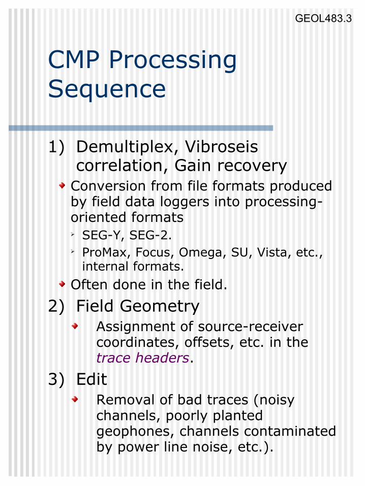
1) Demultiplex, Vibroseis correlation, Gain recovery
Conversion from file formats produced by field data loggers into processing-oriented formats➢ SEG-Y, SEG-2.➢ ProMax, Focus, Omega, SU, Vista, etc.,
internal formats. Often done in the field.
2) Field GeometryAssignment of source-receiver coordinates, offsets, etc. in the trace headers.
3) EditRemoval of bad traces (noisy channels, poorly planted geophones, channels contaminated by power line noise, etc.).

GEOL882.3GEOL483.3
CMP Processing sequence (continued)
4) First arrival pickingMay be semi-automatic or manual;Required for generation of refraction statics; models and for designing the mutes.
5) Elevation staticsBased on geometry information, compensates the travel-time variations caused by variations in source/receiver elevations.Transforms the records as if recorded at a common horizontal datum surface.
6) Refraction staticsBuilds a model for the shallow, low-velocity subsurface;Compensates travel-time variations caused by the shallow velocities.
7) ‘Top’, ‘bottom’, and ‘surgical’ muteEliminates (sets amplitude=0) the time intervals where strong non-reflection energy is present:
First arrivals, ground roll, airwave.

GEOL882.3GEOL483.3
CMP Processing Sequence (continued)
8) Gain recoveryCompensates geometrical spreading;Based on a simple heuristic relation.
9) Trace balanceEqualizes the variations in amplitudes caused by differences in coupling;In true-amplitude processing, replaced with ‘surface-consistent deconvolution’.
10) Deconvolution or wavelet processingCompresses the wavelet in time, attenuates reverberations.Converts the wavelet to zero-phase for viewing
11) Gather, CMP sortOften (in ProMax, Omega, Vista) done by using trace lookup tables instead of creating additional copies of the dataset.
12) Moveout (Radon, τ-p, f-k) filtering Attenuates multiples, ground roll.

GEOL882.3GEOL483.3
Deconvolution
Objectives:1)Compress
the wavelet into a sharp minimum- or zero-phase shape;
2)Remove predictable (short-period multiple) part of the signal;
3)Broaden (flatten) the spectrum.
Deconvolving (inverse) Filter
More on deconvolution in Filtering section later...
GEOL882.3GEOL483.3
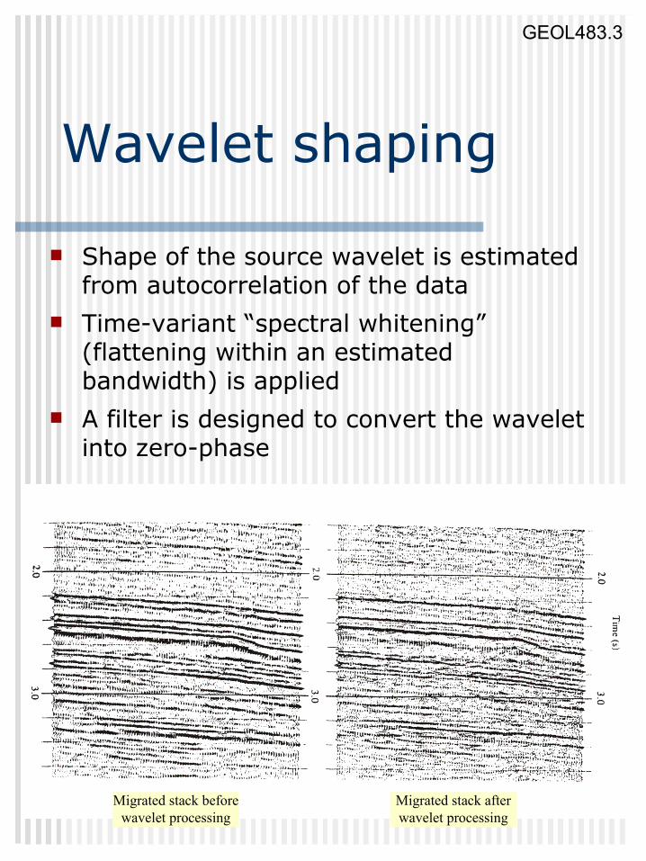
Wavelet shaping
Shape of the source wavelet is estimated from autocorrelation of the data
Time-variant “spectral whitening” (flattening within an estimated bandwidth) is applied
A filter is designed to convert the wavelet into zero-phase
Migrated stack beforewavelet processing
Migrated stack afterwavelet processing

GEOL882.3GEOL483.3
CMP Processing Sequence (continued)
13) Velocity analysisFor each of the CMP gathers, determines the optimal stacking velocity.
14) Dip Moveout (DMO) correctionTransforms the records so that the subsequent NMO+stack work well even in the presence of dipping reflectors.
15) Normal Moveout (NMO) correction
Removes the effects of source-receiver separation from reflection records;Transforms the records as if recorded at normal incidence.
16) Residual staticsRemoves the remaining small travel-time variations caused by inaccurate statics or velocity model
GEOL882.3GEOL483.3
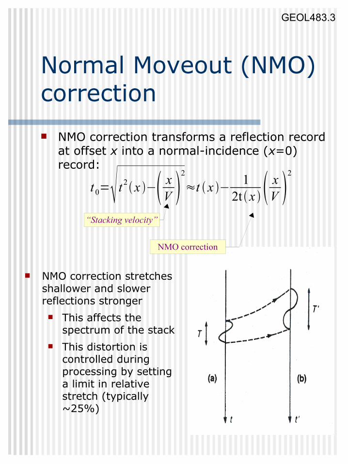
Normal Moveout (NMO) correction NMO correction transforms a reflection record
at offset x into a normal-incidence (x=0) record:
t 0= t 2x − xV
2
≈t x − 12t x x
V 2
“Stacking velocity”
NMO correction stretches shallower and slower reflections stronger This affects the
spectrum of the stack This distortion is
controlled during processing by setting a limit in relative stretch (typically ~25%)
NMO correction

GEOL882.3GEOL483.3
Velocity Analysis
CMP gathers are stacked along trial- velocity hyperbolas and presented in time-velocity diagrams.

GEOL882.3GEOL483.3
Velocity analysis(Common-Velocity Stacks)
Groups of CMP gathers are NMO-corrected (hyperbolas flattened) using a range of trial velocities and stacked.
Velocities are picked at the amplitude peaks and best resolution in the stacks.

GEOL882.3GEOL483.3
NMO→DMO→Migration
DMO assists NMO by correcting for the time delay on an offset trace assuming zero dip.
For a dipping reflector, DMO moves the data to the correct zero-offset trace. Migration further moves it to the subsurface location.
Der
egow
ski,
1986

GEOL882.3GEOL483.3
CMP Processing Sequence (continued)
17) Steps 13-16 above are usually iterated 3-5 times to produce accurate velocity and residual statics models.
Success of velocity analysis depends on the quality of DMO/NMO and residual statics, and vice versa.
18) CMP StackProduces a zero-offset section; Utilizes CMP redundancy to increase the Signal/Noise ratio.Can employ various normalization ideas, e.g., diversity stack
19) MigrationTransforms the zero-offset time section into a depth image;Establishes correct extents and dips of the reflectors.
20) Frequency filtering and displayAttenuates noiseProvides best display for interpretation

GEOL882.3GEOL483.3
Moveout (f-k, τ-p) filtering
Removes coherent events with undesired moveouts
Original CMP gather
NMO appliedapproximate)
Non-horizontalevents removed
and inverse NMO
applied
Multiple
Multiple

GEOL882.3GEOL483.3
Migration A simplified variant of 'inversion'
Inverts 'time section' for true 'depth image'. Establishes true positions and dips of
reflectors. Collapses diffractions.
Migration collapsesdiffraction curves(surfaces in 3-D)
t rx = t02
xV2
t d x=t 0
2 t0
22
xV2

GEOL882.3GEOL483.3
Example: CMP gathers

GEOL882.3GEOL483.3
Example: CMP gathers after NMO correction

GEOL882.3GEOL483.3
Example: CMP gathers after NMO+DMO corrections

GEOL882.3GEOL483.3
Example: Velocity analysis
Without DMO With DMO
GEOL882.3GEOL483.3
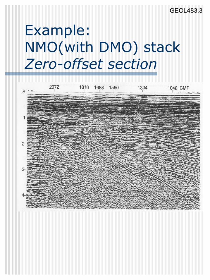
Example: NMO(with DMO) stackZero-offset section

GEOL882.3GEOL483.3
Example: Final migrated stack