geographic signaling system (geo) · page 2-5 – added line card to geo case configurations. page...
TRANSCRIPT

PRINTED IN THE U.S.A.
FIELD REFERENCE MANUAL
GEOGRAPHIC SIGNALING SYSTEM (GEO)
JULY 2008 (REVISED SEPTEMBER 2018)
DOCUMENT NO. SIG-00-05-09 VERSION D
Siemens Mobility 700 East Waterfront Drive Munhall, Pennsylvania 15120 1-800-793-SAFE Copyright © 2008-2018 Siemens Mobility, Inc.
All rights reserved
II SIG-00-05-09 JULY 2008 (REVISED SEPTEMBER 2018)
Version: D
PROPRIETARY INFORMATION The material contained herein constitutes proprietary and confidential information, and is the intellectual property of Siemens Mobility, Inc., Rail Automation (Siemens) protected under United States patent, copyright and/or other laws and international treaty provisions. This information and the software it describes are for authorized use only, and may not be: (i) modified, translated, reverse engineered, decompiled, disassembled or used to create derivative works; (ii) copied or reproduced for any reason other than specific application needs; or (iii) rented, leased, lent, sublicensed, distributed, remarketed, or in any way transferred; without the prior written authorization of Siemens. This proprietary notice and any other associated labels may not be removed.
TRANSLATIONS The manuals and product information of Siemens Mobility, Inc. are intended to be produced and read in English. Any translation of the manuals and product information are unofficial and can be imprecise and inaccurate in whole or in part. Siemens Mobility, Inc. does not warrant the accuracy, reliability, or timeliness of any information contained in any translation of manual or product information from its original official released version in English and shall not be liable for any losses caused by such reliance on the accuracy, reliability, or timeliness of such information. Any person or entity that relies on translated information does so at his or her own risk.
WARRANTY INFORMATION Siemens Mobility, Inc. warranty policy is as stated in the current Terms and Conditions of Sale document. Warranty adjustments will not be allowed for products or components which have been subjected to abuse, alteration, improper handling or installation, or which have not been operated in accordance with Seller's instructions. Alteration or removal of any serial number or identification mark voids the warranty.
SALES AND SERVICE LOCATIONS Technical assistance and sales information on Siemens Mobility, Inc. products may be obtained at the following locations:
SIEMENS MOBILITY, INC. RAIL AUTOMATION SIEMENS MOBILITY, INC. RAIL AUTOMATION
2400 NELSON MILLER PARKWAY 939 S. MAIN STREET
LOUISVILLE, KENTUCKY 40223 MARION, KENTUCKY 42064
TELEPHONE: (502) 618-8800 TELEPHONE: (270) 918-7800 FAX: (502) 618-8810 CUSTOMER SERVICE: (800) 626-2710 SALES & SERVICE: (800) 626-2710 TECHNICAL SUPPORT: (800) 793-7233 WEB SITE: USA Rail Automation Site FAX: (270) 918-7830
FCC RULES COMPLIANCE The equipment covered in this manual has been tested and found to comply with the limits for Class A digital devices, pursuant to part 15 of the FCC Rules. These limits are designed to provide reasonable protection against harmful interference when the equipment is operated in a commercial environment. This equipment generates, uses, and can radiate radio frequency energy and, if not installed and used in accordance with the instruction manual, may cause harmful interference to radio communications. Operation of this equipment in a residential area is likely to cause harmful interference in which case the user will be required to correct the interference at his/her own expense.

III SIG-00-05-09 JULY 2008 (REVISED SEPTEMBER 2018)
Version: D
DOCUMENT HISTORY
Version Release Date
Sections Changed
Details of Change
C July 2008
All Added references to Line Module throughout document. Additional changes/additions as noted.
Chapter 1
Page 1-5 - Added example drawing illustrating use of Line modules to span crossings.
Chapter 2
Page 2-4 - Added Line module and purpose to I/O Modules table.
Page 2-5 – Added Line card to GEO case configurations.
Page 2-6 – Added Line card to GEO block diagram.
Page 2-7 – Added Line card to GEO case slot drawing.
Page 2-14 – Added bullet description for using DIAG port under Track Module Features.
Page 2-15 – Added Line Module Information Path, Line Module Compatibility and Features.
Page 2-19 – Added Note that broken rail detection is not provided when using Line cards.
Chapter 3
Page 3-7 – Added Module Operating Parameters for CPU A80403. Also added CAUTION about setting operating parameters incorrectly and that the railroad assumes responsibility for its field-configured operating parameters.
Page 3-11 – Added Module Operating Parameters for Track Module.
Page 3-14 – Added Line Module Overview, Shorted Line Detection, and Module Operating Parameters.
Page 3-15 – Added Line Module External Filtering, Code Formats, and Event Recording.
Page 3-16 – Added Line Module Indicators and Connectors with drawing.
Page 3-17 & 3-18 – Added table for Line Module display and indicator functions.
Page 3-19 – Added paragraph under CLS Lamp Outputs explaining that lamp output can be programmed via the DT to reduce input current requirements and extend battery life.
Page 3-22 – Added CLS Module Operating Parameters.
IV SIG-00-05-09 JULY 2008 (REVISED SEPTEMBER 2018)
Version: D
Page 3-24 – Added information about SLS models: -01 without faceplate, -03 with faceplate. Added to first bullet: Six signal position feedback “vital” inputs. Added paragraph explaining that lamp output can be programmed via the DT to reduce input current requirements and extend battery life.
Page 3-25 – Added SLS Indicators and Connectors with updated faceplate and table details.
Page 3-26 – Added SLS Module Operating Parameters and new graphic of A53263-03 with faceplate.
Page 3-28 – Added RIO Module Operating Parameters.
Page 3-31 – Added VPI Module Operating Parameters.
Chapter 4
No change to content.
Chapter 5
No change to content.
Chapter 6
Page 6-6 - Added Line module to Basic Operation Menu Map.
Page 6-7 - Added Line module to Query Mode Viewing Parameters.
Pages 6-13 and 6-14 – Added Line Query and all related information.
Page 6-32 - Added Line module to Change Mode Accessing Parameters.
Page 6-37 – Added Line Change Mode and all related information.
Chapter 7
Page 7-4 - Added references to procedures for adjusting Line module transmit voltage and receive threshold in steps 7 & 8 of Setup Process.
Page 7-21 – Added procedure on “How to Set Line Module Transmit Voltage”.
Page 7-22 – Added procedure on “How to Set Line Module Receive Threshold”.
Chapter 8
Page 8-29 – Added details on connecting an RS-232 adaptor cable to a “revision A” or “revision B” Search Light module.
Chapter 9
Page 9-7 – Added Troubleshooting Action bullet to check for open or shorted line wire if using Line cards.

V SIG-00-05-09 JULY 2008 (REVISED SEPTEMBER 2018)
Version: D
Page 9-13 – Added Line Module to Health and Status Quick Reference Chart.
Pages 9-16, 9-17 & 9-21 – Added Line Module to flowcharting.
Chapter 10
Pages 10-18 thru 10-23 – Added information on Reading GEO Logs.
Chapter 11
No change to content.
Appendix A and Appendix B
No change to content.
Appendix C
New appendix – “Module Failure Descriptions”.
Appendix D
New appendix – “GEO Track Circuit Troubleshooting Guide”.
C.1 April 2014
All Rebranded all document for Siemens. Updated SEAR II battery information on page 3-45.
D Sep 2018
All Reformatted, added information on CPU III use and WebUI functionality, Deleted Obsolete information, Updated branding on graphics, reorganized content, removed Maintainer Interface Content.

VI SIG-00-05-09 JULY 2008 (REVISED SEPTEMBER 2018)
Version: D
Table of Contents SECTION 1 Introduction .................................................................................................................. 1-1
1.0 GEO Product Overview .............................................................................................................. 1-1
1.1 Capabilities: ............................................................................................................................ 1-1
1.2 Application: ............................................................................................................................. 1-1
1.3 Versatility ................................................................................................................................ 1-1
1.4 Advantages ............................................................................................................................. 1-2
1.5 Compatibility ........................................................................................................................... 1-2
1.6 Flexibility ................................................................................................................................. 1-2
1.7 Basic System Design .............................................................................................................. 1-3
SECTION 2 Primary Equipment Description .................................................................................... 1-1
2.0 Unit Configuration ....................................................................................................................... 2-1
2.1 Chassis Configuration ............................................................................................................. 2-1
2.2 End of Siding Configuration .................................................................................................... 2-2
2.3 Hardware Identification ........................................................................................................... 2-4
2.4 Application Logic ..................................................................................................................... 2-4
2.5 Color Light Signal Circuits ....................................................................................................... 2-5
2.6 Search Light Signal Circuits .................................................................................................... 2-6
2.7 Input/Output Circuits ............................................................................................................... 2-6
2.8 Track Circuits .......................................................................................................................... 2-7
2.9 Track Codes ........................................................................................................................... 2-8
2.10 Shunting ............................................................................................................................... 2-10
2.11 Diagnostic Port On CPU II+ .................................................................................................. 2-11
2.12 Laptop Port on CPU III .......................................................................................................... 2-11
2.13 Maintenance Interface of CPU .............................................................................................. 2-12
2.14 Viewing and Changing System Settings on the CPU II+ ....................................................... 2-12
2.15 Viewing and Changing System Settings on the CPU III ........................................................ 2-12
2.16 External COmmunications .................................................................................................... 2-12
2.17 GEO Non-Vital Interfaces ..................................................................................................... 2-13
2.18 Wayside Access Gateway .................................................................................................... 2-13
SECTION 3 Primary Equipment Description .................................................................................... 2-1
3.0 Primary Equipment Overview ..................................................................................................... 3-1
3.1 Chassis Description ................................................................................................................ 3-1
3.2 Track Module (A53285) .......................................................................................................... 3-7
3.3 Line Module (A53254) ........................................................................................................... 3-11

VII SIG-00-05-09 JULY 2008 (REVISED SEPTEMBER 2018)
Version: D
3.4 Color Light Signal Module (A53284) ..................................................................................... 3-15
3.5 SLS Module (A53263) ........................................................................................................... 3-20
3.6 RIO Module (A80413) ........................................................................................................... 3-24
SECTION 4 Auxiliary Equipment Overview .................................................................................... 3-28
4.0 Universal Local Control Panel (ULCP) A50692 ........................................................................ 4-28
4.2 End of Siding Application ...................................................................................................... 4-31
4.3 Siemens Event Analyzer and Recorder II (SEAR II) .............................................................. 4-35
SECTION 5 Equipment Installation ................................................................................................ 4-36
5.0 Wiring Terminals ...................................................................................................................... 5-36
5.1 Overview ............................................................................................................................... 5-36
5.2 Battery, LAN, and Communication Interface ......................................................................... 5-36
5.3 Track and I/O Connectors and Fuses ................................................................................... 5-37
5.4 I/O Connectors for Optional Modules .................................................................................... 5-39
5.5 Installation Overview ............................................................................................................. 5-40
5.6 Bungalow Checks ................................................................................................................. 5-42
5.7 Install Chassis....................................................................................................................... 5-43
5.8 Typical Color Light Application Wiring ................................................................................... 5-47
5.9 Typical Search Light Application Wiring ................................................................................ 5-48
5.10 Apply Power and Observe System Startup Sequence .......................................................... 5-49
SECTION 6 Maintainer Interface...................................................................................................... 5-1
6.0 Purpose ...................................................................................................................................... 6-1
6.1 Viewing System Settings ........................................................................................................ 6-1
SECTION 7 System Setup and Configuration .................................................................................. 6-1
7.0 Setup and Configuration Process ............................................................................................... 7-1
7.1 System Initialization ................................................................................................................ 7-2
7.2 Configuration Errors ................................................................................................................ 7-4
7.3 How to Load a New MCF via WebUI ....................................................................................... 7-5
7.4 How to Set System Time ........................................................................................................ 7-8
7.5 How to Set System Date (CPU II+) ....................................................................................... 7-11
7.6 How to Set Track Module voltage and Current Limits ............................................................ 7-12
7.7 How to Set a Track Module Receive Current ........................................................................ 7-14
7.8 How to Set Line Module Transmit Voltage and Receive Threshold ....................................... 7-16
7.9 How to Set Lamp Voltage for Color Light Signal Heads ........................................................ 7-17
7.10 How to Set Search Light Mechanism Parameters ................................................................. 7-18
SECTION 8 Maintenance ................................................................................................................ 7-1
VIII SIG-00-05-09 JULY 2008 (REVISED SEPTEMBER 2018)
Version: D
8.0 Tasks ......................................................................................................................................... 8-1
8.1 Viewing System Settings ........................................................................................................ 8-1
8.2 Test Equipment / Tools ........................................................................................................... 8-1
8.3 How to Check Battery Voltage ................................................................................................ 8-2
8.4 How to Check Track Circuit..................................................................................................... 8-3
8.5 How to Check Signal Lamp Parameters.................................................................................. 8-4
8.6 GEO Module/MEF Replacement Test Procedures .................................................................. 8-4
8.7 Test Procedure 1: GEO Track Module / MEF Replacement .................................................... 8-5
8.8 Test Procedure 2: CPU Module VLP/CP MEF Replacement ................................................. 8-12
8.9 Test Procedure 3: GEO I/O Module/MEF Replacement with the DT Tool ............................. 8-17
8.10 Test Procedure 4: Search Light Module / MEF Replacement ................................................ 8-19
SECTION 9 Troubleshooting ........................................................................................................... 8-1
9.0 Overview .................................................................................................................................... 9-1
9.1 ESD Precautions .................................................................................................................... 9-1
9.2 Tools and Equipment Needed ................................................................................................. 9-1
9.3 Standard Troubleshooting Procedure ..................................................................................... 9-2
9.4 Troubleshooting Notes and Tips ............................................................................................. 9-4
9.5 Failure Symptoms ................................................................................................................... 9-6
9.6 Using the Troubleshooting Flowcharts .................................................................................. 9-10
9.7 Troubleshooting Using the SEAR II ....................................................................................... 9-21
9.8 Troubleshooting Intermittent Problems ................................................................................. 9-23
9.9 Troubleshooting with a Laptop ComputeR ............................................................................ 9-23
9.10 How to Connect DT to a GEO ............................................................................................... 9-24
9.11 How to Check GEO Status.................................................................................................... 9-27
9.12 How to Adjust Voltages and Current ..................................................................................... 9-28
9.13 Reading GEO Logs ............................................................................................................... 9-29
9.14 How to View the Status (Event) Log ...................................................................................... 9-35
9.15 How to View the Summary Log ............................................................................................. 9-37
9.16 How to View the ATCS Communication Links ....................................................................... 9-37
SECTION 10 Track Circuit Troubleshooting Guide .......................................................................... 9-39
10.0 Introduction ............................................................................................................................ 10-39
10.1 Siemens Mobility GEO Track Module Displays (“d” “E” and/or “F”) ..................................... 10-39
10.2 Track Circuit Trouble Symptoms ......................................................................................... 10-41
10.3 GEO Track Inductors .......................................................................................................... 10-42
10.4 Reverse Polarity of Track Circuit Wiring .............................................................................. 10-43
IX SIG-00-05-09 JULY 2008 (REVISED SEPTEMBER 2018)
Version: D
10.5 Bad Insulated Joint – Without Code 5 Present .................................................................... 10-43
10.6 Bad Insulated Joint – With Code 5 Present ......................................................................... 10-44
10.7 Track Circuit Setup Procedure ............................................................................................ 10-45
10.8 Track Voltage Table ............................................................................................................ 10-48
Appendix A Electro Code™ Track Code Rates ............................................................................ A-1
Appendix B Module Failure Descriptions ..................................................................................... B-1

X SIG-00-05-09 JULY 2008 (REVISED SEPTEMBER 2018)
Version: D
List of Figures Figure 1-1 Using Coded Track and Line Modules to Span Crossings................................................... 1-2
Figure 2-1 Simplified Block Diagram .................................................................................................... 2-3
Figure 2-2 GEO Chassis ...................................................................................................................... 2-4
Figure 2-3 Vital Code Timing ............................................................................................................... 2-9
Figure 2-4 Non-Vital Codes ................................................................................................................ 2-10
Figure 3-1 CPU II+ Front Panel ............................................................................................................. 3-4
Figure 3-2 CPU III Front Panel .............................................................................................................. 3-5
Figure 3-3 Track Module Front Panel .................................................................................................... 3-8
Figure 3-4 Line Module LEDs and Display .......................................................................................... 3-13
Figure 3-5 Color Light Signal Front Panel ........................................................................................... 3-19
Figure 3-6 Search Light Signal Front Panel ......................................................................................... 3-22
Figure 3-7 RIO Front Panel ................................................................................................................. 3-26
Figure 4-1 Universal Local Control Panel (ULCP) Front Panel ............................................................ 4-28
Figure 4-2 Universal Local Control Panel Controls and Indicators ....................................................... 4-29
Figure 4-3 ULCP Rear Connectors ..................................................................................................... 4-31
Figure 4-4 Generic Overlay Example .................................................................................................. 4-32
Figure 5-1 GEO Wiring Terminal Panel ............................................................................................... 5-36
Figure 5-2 GEO External Filtering ....................................................................................................... 5-38
Figure 5-3 Wiring Slots 1 Through 7.................................................................................................... 5-39
Figure 5-4 Inserting Wires ................................................................................................................... 5-44
Figure 5-5 GEO Connector Pairs ........................................................................................................ 5-45
Figure 5-6 Key Pairs Example............................................................................................................. 5-45
Figure 5-7 Track Wire Connection Diagram ........................................................................................ 5-46
Figure 5-8 Color Light Wiring Diagram ................................................................................................ 5-47
Figure 5-9 Search Light Wiring Diagram ............................................................................................. 5-48
Figure 5-10 Connecting Meter to Terminal .......................................................................................... 5-52
Figure 7-1 Unsecure Connection Warning ............................................................................................ 7-6
Figure 7-2 WebUI Login Screen ............................................................................................................ 7-7
Figure 7-3 WebUI Tool Bar ................................................................................................................... 7-7
Figure 7-4 MCF Upload Screen ............................................................................................................ 7-7
Figure 7-5 Unlocking Parameters .......................................................................................................... 7-8
Figure 7-6 Uploading Status ................................................................................................................. 7-8
Figure 7-7 Enter Change Mode for CPU ............................................................................................... 7-9
Figure 7-8 Setting System Time and Date........................................................................................... 7-10

XI SIG-00-05-09 JULY 2008 (REVISED SEPTEMBER 2018)
Version: D
Figure 7-9 Track Module Voltage and Current .................................................................................... 7-13
Figure 7-10 Saved Successfully .......................................................................................................... 7-13
Figure 7-11 Set Line Module Transmit Voltage ................................................................................... 7-17
Figure 7-12 Adjust Lamp Voltage ........................................................................................................ 7-18
Figure 7-13 Setting Search Light Parameters ..................................................................................... 7-19
Figure 7-14 Unlock Parameters .......................................................................................................... 7-20
Figure 7-15 Search Light Debounce Parameter .................................................................................. 7-20
Figure 8-1 Checking Battery Voltage Manually ..................................................................................... 8-2
Figure 8-2 I/O View Using WebUI ......................................................................................................... 8-3
Figure 8-3 MEF Version Check Using WebUI ....................................................................................... 8-7
Figure 8-4 Check Serial Port Connection .............................................................................................. 8-8
Figure 8-5 CPU/Module Reboot Warning .............................................................................................. 8-9
Figure 8-6 Change Track Module MEF ................................................................................................. 8-9
Figure 8-7 Browse for Track Module MEF ............................................................................................. 8-9
Figure 8-8 Track Module MEF Upload Status ..................................................................................... 8-10
Figure 8-9 Confirm MCF and MEFs .................................................................................................... 8-11
Figure 8-10 Reboot Required .............................................................................................................. 8-15
Figure 8-11 CP MEF Upload Successful ............................................................................................. 8-16
Figure 9-1 Fix Confirmation Flow ........................................................................................................ 9-11
Figure 9-2 Further Troubleshooting ..................................................................................................... 9-12
Figure 9-3 Unsecure Connection Warning .......................................................................................... 9-26
Figure 9-4 WebUI Login Screen .......................................................................................................... 9-27
Figure 9-5 WebUI Tool Bar ............................................................................................................... 9-27
Figure 9-6 Event Log in WebUI ........................................................................................................... 9-30
Figure 9-7 Change Verbosity Settings ................................................................................................. 9-35
Figure 9-8 Adjust Verbosity of Status Log ........................................................................................... 9-36
Figure 9-9 Summary View of Log ........................................................................................................ 9-37
Figure 9-10 ATCS Communication Link Status Monitor ...................................................................... 9-38

XII SIG-00-05-09 JULY 2008 (REVISED SEPTEMBER 2018)
Version: D
List of Tables Table 2-1 CPU Unit Description ............................................................................................................ 2-1
Table 2-2 Module Description ............................................................................................................... 2-2
Table 2-3 Track Code Definitions ........................................................................................................ 2-11
Table 2-4 Commonly Interfacing External Devices .............................................................................. 2-13
Table 3-1 Unit Operating Parameters .................................................................................................... 3-3
Table 3-2 CPU User Interface ............................................................................................................... 3-6
Table 3-3 Track Module Operating Parameters .................................................................................... 3-8
Table 3-4 Track Module (A53285) Indicators and Connectors .............................................................. 3-9
Table 3-5 Line Module Operating Parameters ..................................................................................... 3-11
Table 3-6 Line Module (A53254) Indicators and Connectors ............................................................... 3-14
Table 3-7 Color Light Signal Operating Parameters ............................................................................ 3-18
Table 3-8 Color Light Signal Module (A53284) Indicators and Connectors ......................................... 3-20
Table 3-9 Search Light Signal Indicators and Connectors ................................................................... 3-23
Table 3-10 Search Light Operating Parameters .................................................................................. 3-23
Table 3-11 RIO Operating Parameters ................................................................................................ 3-25
Table 3-12 RIO Indicators and Connectors ......................................................................................... 3-27
Table 4-1 ULCP Controls .................................................................................................................... 4-30
Table 4-2 ULCP Indicators .................................................................................................................. 4-30
Table 4-3 Standard Pushbutton Labels on ULCP ................................................................................ 4-32
Table 4-4 Standard LED Labels on ULCP ........................................................................................... 4-33
Table 5-1 CPU II+ Startup Sequence .................................................................................................. 5-49
Table 5-2 CPU III Startup Sequence ................................................................................................... 5-51
Table 6-1 Push-button Functions of CPU Module ................................................................................. 6-2
Table 7-1 Startup Sequence for CPU II+ ............................................................................................... 7-2
Table 7-2 Startup Sequence for CPU III ................................................................................................ 7-3
Table 7-3 Fatal CIC Error Messages ..................................................................................................... 7-4
Table 7-4 Fatal Error Codes .................................................................................................................. 7-5
Table 7-5 Track Voltage Table ............................................................................................................ 7-12
Table 7-6 GEO Track Circuit Setup Checklist ..................................................................................... 7-15
Table 7-7 Track Circuit Checklist Instructions ..................................................................................... 7-16
Table 8-1 Track Module Receive Currents .......................................................................................... 8-12
Table 8-2 Track Circuit RX Jumper Adjustment Table ......................................................................... 8-12
Table 9-1 GEO Troubleshooting Procedure .......................................................................................... 9-2
Table 9-2 Health and Status Quick Reference Guide ............................................................................ 9-7
XIII SIG-00-05-09 JULY 2008 (REVISED SEPTEMBER 2018)
Version: D
Table 9-3 Observation Recommendations .......................................................................................... 9-10
Table A-1 EC-4 - Short/Alternating Freight Track Code Rates (Transmitter) ......................................... A-1
Table A-2 EC-4 Plus—Short/Alternating Freight Track Code Rates (Transmitter) ................................. A-2
Table A-3 EC-4 Plus (and EC-4) - Freight Track Code Rates (Transmitter) .......................................... A-3
Table A-4 Freight Track Code Rates (Receiver).................................................................................... A-4
Table A-5 Control Timing Diagram ........................................................................................................ A-5
Table B-1 CLS Module Failure Reference Table ................................................................................... B-1
Table B-2 LIN Module Failure Reference Table .................................................................................... B-7
Table B-3 RIO Module Failure Reference Table ................................................................................. B-12
Table B-4 SLS Module Failure Reference Table ................................................................................. B-13
Table B-5 TRK Module Failure Reference Table ................................................................................. B-22

XIV SIG-00-05-09 JULY 2008 (REVISED SEPTEMBER 2018)
Version: D
NOTES, CAUTIONS, AND WARNINGS Throughout this manual, notes, cautions, and warnings are frequently used to direct the reader’s attention to specific information. Use of the three terms is defined as follows:
WARNING INDICATES A POTENTIALLY HAZARDOUS SITUATION WHICH, IF NOT AVOIDED, COULD RESULT IN DEATH OR SERIOUS INJURY. WARNINGS ALWAYS TAKE PRECEDENCE OVER NOTES, CAUTIONS, AND ALL OTHER INFORMATION.
CAUTION REFERS TO PROPER PROCEDURES OR PRACTICES WHICH IF NOT STRICTLY OBSERVED, COULD RESULT IN A POTENTIALLY HAZARDOUS SITUATION AND/OR POSSIBLE DAMAGE TO EQUIPMENT. CAUTIONS TAKE PRECEDENCE OVER NOTES AND ALL OTHER INFORMATION, EXCEPT WARNINGS.
NOTE Generally used to highlight certain information relating to the topic under discussion.
If there are any questions, contact Siemens Mobility, Inc. Application Engineering

XV SIG-00-05-09 JULY 2008 (REVISED SEPTEMBER 2018)
Version: D
ELECTROSTATIC DISCHARGE (ESD) PRECAUTIONS Static electricity can damage electronic circuitry, particularly low voltage components such as the integrated circuits commonly used throughout the electronics industry. Therefore, procedures have been adopted industry-wide which make it possible to avoid the sometimes invisible damage caused by electrostatic discharge (ESD) during the handling, shipping, and storage of electronic modules and components. Siemens Mobility, Inc. has instituted these practices at its manufacturing facility and encourages its customers to adopt them as well to lessen the likelihood of equipment damage in the field due to ESD. Some of the basic protective practices include the following:
• Ground yourself before touching card cages, assemblies, modules, or components. • Remove power from card cages and assemblies before removing or installing modules. • Remove circuit boards (modules) from card cages by the ejector lever only. If an ejector lever is
not provided, grasp the edge of the circuit board but avoid touching circuit traces or components. • Handle circuit boards by the edges only. • Never physically touch circuit board or connector contact fingers or allow these fingers to come in
contact with an insulator (e.g., plastic, rubber, etc.). • When not in use, place circuit boards in approved static-shielding bags, contact fingers first.
Remove circuit boards from static-shielding bags by grasping the ejector lever or the edge of the board only. Each bag should include a caution label on the outside indicating static-sensitive contents.
• Cover workbench surfaces used for repair of electronic equipment with static dissipative workbench matting.
• Use integrated circuit extractor/inserter tools designed to remove and install electrostatic-sensitive integrated circuit devices such as PROM’s (OK Industries, Inc., Model EX-2 Extractor and Model MOS-40 Inserter (or equivalent) are highly recommended).
• Utilize only anti-static cushioning material in equipment shipping and storage containers.
For information concerning ESD material applications, please contact the Technical Support Staff at 1-800-793-7233. ESD Awareness Classes and additional ESD product information are also available through the Technical Support Staff.

XVI SIG-00-05-09 JULY 2008 (REVISED SEPTEMBER 2018)
Version: D
GLOSSARY
TERM DESCRIPTION
AAR: Association of American Railroads – An organization that establishes uniformity and standardization among different railroad systems.
AF Audio Frequency
AFO Audio Frequency Overlay
Application Logic
A program that defines how a GEO unit will monitor and control signaling equipment at a specific location. The program is loaded into the Chassis ID Chip (CIC) on the GEO chassis.
AREMA: American Railroad Equipment Manufacturing Association – An organization that supersedes AAR.
ATCS: Advanced Train Control System – A set of standards compiled by the AAR for controlling all aspects of train operation.
BIST Built In Self Test – A test program that is part of the firmware in a system. BIST typically executes automatically during system initialization. On vital modules, BIST continues to execute throughout runtime.
Boot Startup sequence for the microprocessor. On the GEO system this can be accomplished by removing then reseating the CPU module or by pulling the chassis fuse for a few seconds.
CCN Configuration Check Number – the 32 bit CRC of the configuration data.
CIC Chassis ID Chip – A serial EEPROM physically located on the GEO chassis and used to store the UCN, SIN, and site/module parameters.
CLS Color Light Signal - The GEO module used to control and monitor Color Light Signals.
Code Fail Loss of communication with a supervisory control system or other centralized train control system.
Code Rate Track-based waveform used to convey information between signal sites.
Control Message
A request to the signaling system, such as a signal request or a switch request.
CP Communication Processor - The processor mounted on the CPU II+ module used to control communication and non-vital processing.
CRC Cyclical Redundancy Check – Used to determine that data has not been corrupted.

XVII SIG-00-05-09 JULY 2008 (REVISED SEPTEMBER 2018)
Version: D
TERM DESCRIPTION
CWR Continuous Welded Rail
Debounce The amount of time an input must remain constant to be considered a valid input. Debounce prevents random spikes of electrical energy from energizing an input.
DC Offsets Condition in which one rail is kept at one voltage relative to the other even when the track circuit is disconnected.
DOT Number Department of Transportation crossing inventory number assigned to every highway-railroad crossing that consists of six numbers with an alpha suffix.
ECD: External Configuration Device – A serial EEPROM (Flash Memory) device mounted inside the chassis of the GEO unit. The ECD is used to store site-specific configuration data (MCF, SIN, UCN, and card parameters) for the CPU.
Echelon LAN GEO uses the Echelon connector on the front of the chassis to provide a two-wire, twisted-pair communication connection between the GEO system and other Siemens electronics equipment located within the same bungalow.
FEN Foreign Energy – An indication that is displayed when a signal lamp is being energized by a source other than GEO.
Firmware Software saved in ROM within a module and moved into main memory RAM for runtime use when the system is powered up.
Fleeting Refers to signals left in non-restrictive aspect to allow follow-on trains. Fleeting is a control that allows a signal to re-line automatically. For example, let’s presume that the signal is lined up. The train proceeds through the control point, then the signal lines back up after the train is clear of the control point. Fleeting is used when testing a location (FRA/cut-in) or when there is a communication failure and the location can be lined up in one direction locally and left.
FLASH MEMORY
A type of non-volatile memory that can be reprogrammed in-circuit via software.
HD Pole Line Wires strung along wayside poles for carrying signal aspect and other train control information. HD stands for Home/Distant, referring to track block signals.
Interlocking An automatic or manual arrangement of signals and appliances so interconnected that their movements must succeed each other in proper sequence and for which interlocking rules are in effect.

XVIII SIG-00-05-09 JULY 2008 (REVISED SEPTEMBER 2018)
Version: D
TERM DESCRIPTION
LAN Local Area Network – A communications connection (wired or wireless) between two or more pieces of electronic equipment. The connection allows each piece of electronic equipment to exchange data with other equipment in the LAN. GEO uses the Echelon connector on the front of the chassis to provide a two-wire, twisted-pair connection between the GEO unit and other Siemens electronics equipment located within the same bungalow.
LCP Local Control Panel – A control and display interface device that connects to the SEAR II and allows field personnel to perform maintenance and troubleshooting procedures at a location.
LED Light-Emitting-Diode - A solid-state indicator.
LIN Line - The GEO module used to transmit and receive coded track patterns over cable.
LOR Lamp Out Relay - A GEO status indication using the DTU or the maintainers interface that a signal lamp filament has been tested with current and failed.
LOS Loss of Shunt – Commonly due to rust and/or rail contamination. LOS timers provide a pick up delay function.
MEF: Module Executable File – The executive software running in the CPU or I/O Modules. The user can download the MEF through the Diag port to update the software.
MCF: Module Configuration File – The GCP application logic file.
MCF CRC Module Configuration File Cyclic Redundancy Check - A configuration validation number calculated from the contents of an approved MCF and issued to be stored in the CIC for the purpose of verifying proper configuration.
MCI Error Module Configuration Index error – A GEO boot error indicating an incompatibility between the installed MCF and the MEF on one or more modules.
MEF Module Executable File – Specific executive software running in each of the GEO modules. This software controls how the module interacts with the CPU II+ module to perform tasks.
Reboot To cause the system to restart by removing power for a few seconds, then reapplying power. On the GEO system this can be accomplished by removing then reseating the CPU module or by pulling the chassis fuse for a few seconds.
XIX SIG-00-05-09 JULY 2008 (REVISED SEPTEMBER 2018)
Version: D
TERM DESCRIPTION
Red-Retaining Relay
A safety function whereby a failure on any Color Light (CLS) module or group of CLS modules, or the associated lamp circuit(s), where a red-retaining relay output is assigned to the module or group, will cause all block signals controlled by the CLS module or associated group to turn red. (Other common names for this function include V-stop, M-stop and Signal Stop relay.)
RS-232 A communication protocol used to exchange serial binary data between
electronic devices. Uses a DB-25 or DB-9 connector. Distance between devices must be less than 60 meters.
RS-485 A higher speed version of RS-232 that supports longer distances and multiple devices.
RX Receive or Receiver
SEAR II Siemens Event Analyzer and Recorder II – Provides recording, reporting of
automated testing, and monitoring functions. For more detail, see Chapter 3 in this manual.
Serial Bus The communication path that carries messages between the CPU and I/O
modules installed in the GEO chassis. The serial bus is a set of solder runs on the motherboard (backplane) of the chassis.
Shunt An action or device that places a low resistance between opposite rails in a track circuit and pulls down the voltage of track code signals.
Signal Aspect The appearance of a fixed signal conveying an indication as viewed from the direction of an approaching train; the appearance of a cab signal conveying an indication as viewed by an observer in the cab.
SIN: Site Identification Number – The 12-digit ATCS address for the The SIN has the form 7.RRR.LLL.GGG.SS stored in binary coded decimal, with each digit in one nibble. The digit 0 is represented by “A” and 0 is used as a null byte.
Track Circuit Defined by AREMA as “An electrical circuit of which the rails of a track form a part.” A track circuit’s limits are established by the use of insulated rail joints.
TRK Track – The GEO module used to transmit and receive coded track patterns for railroad track circuits.
UCN Unique Check Number – This number is used to validate that vital program parameters are set as intended by the application designer. If the entered UCN does not match the calculate UCN, the GEO system will not energize any signals or outputs.
XX SIG-00-05-09 JULY 2008 (REVISED SEPTEMBER 2018)
Version: D
TERM DESCRIPTION
ULCP Universal Local Control Panel – Same as LCP.
VLO Vital Lamp Output – A software-driven vital hardware output which drives a lamp on a Color Light Signal to display a commanded aspect and verifies the lamp is operational (not shorted or out).
VLP Vital Logic Processor -- The processor mounted on the CPU module that is
responsible for vital processing.
VPI: Vital Parallel Input – An input used to read a vital relay contact.
VRO: Vital Relay Output – An output used to drive a vital relay.
WAG Wayside Access Gateway – A protocol/media converter connecting the Echelon bus to Ethernet or RS-485/RS-232.

INTRODUCTION
1-1 SIG-00-05-09 JULY 2008 (REVISED SEPTEMBER 2018)
Version: D
SECTION 1 INTRODUCTION
1.0 GEO PRODUCT OVERVIEW GEO® is a vital microprocessor-controlled signaling unit manufactured by Siemens Mobility. It monitors and controls switches, signals, and relays at wayside locations along railroad tracks.
1.1 CAPABILITIES:
• Transmit and receive electronic coded track/line circuit messages. • Monitor and control remote external devices. • Provide all vital logic functions at intermediate locations, end of sidings, and single or multiple
switch interlockings. • Interface with relay-based control points. • Interface with a variety of signaling systems produced by other manufacturers.
1.2 APPLICATION:
• GEO replaces relay-based logic circuits with solid state digital logic circuits.
GEO is typically installed to replace:
• Relay-based control points. • Relay-based intermediate locations. • Stepper units. • LCS units.
When equipped with a data radio, GEO can also replace pole-line wires and communicate with dispatch centers.
1.3 VERSATILITY
• GEO units can be configured to perform vital and non-vital tasks at almost any location, regardless of how simple or complex.
• Some examples of GEO versatility include: o Monitoring and reporting position of a remote switch. o Monitoring, controlling, and reporting status of a remote signal. o Controlling an intermediate location. o Controlling an end-of-siding. o Controlling multiple switch interlockings. o Functioning as a coded track circuit repeater
INTRODUCTION
1-2 SIG-00-05-09 JULY 2008 (REVISED SEPTEMBER 2018)
Version: D
1.4 ADVANTAGES GEO units offer several advantages over systems produced by other signal manufacturers. These include:
• Increased track circuit lengths – up to 18,000 feet for DC coded track circuits. • Vitality – circuit cards (modules) are “hot-swappable” i.e. cards can be replaced without shutting
down power to the unit. • Stability – the GEO chassis and each module incorporate extensive lightning and surge
protection. • Interchangeability – all GEO modules can be interchanged between other GEO units without
module reconfiguration. • User-friendly – the graphical interface simplifies maintenance and troubleshooting tasks. • 24-hour technical support: 1-800-793-7233
1.5 COMPATIBILITY The GEO programmable track circuit interface allows GEO units to communicate with equipment produced by other signal manufacturers.
GEO track circuit units are compatible with:
• Electro Code™ II/III/4, 4 Plus and 5 • Genrakode™ • Vital Harmon Logic Controller (VHLC)™ track circuits
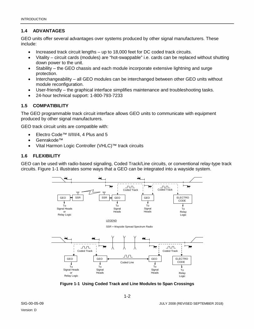
1.6 FLEXIBILITY GEO can be used with radio-based signaling, Coded Track/Line circuits, or conventional relay-type track circuits. Figure 1-1 illustrates some ways that a GEO can be integrated into a wayside system.
Figure 1-1 Using Coded Track and Line Modules to Span Crossings
ELECTROCODE
GEOSSR
ToSignalHeads
ToRelayLogic
LEGEND
SSR = Wayside Spread Spectrum Radio
Coded Track Coded Track
ToSignalHeads
SSRGEO
ToSignal Heads
orRelay Logic
GEO
ELECTROCODE
GEO
ToSignalHeads
ToRelayLogic
Coded LineTo
SignalHeads
GEO
ToSignal Heads
orRelay Logic
GEO
Coded Track Coded Track

INTRODUCTION
1-3 SIG-00-05-09 JULY 2008 (REVISED SEPTEMBER 2018)
Version: D
1.7 BASIC SYSTEM DESIGN
1.7.1 Design Concept Each GEO unit contains one Central Processing Unit (CPU) module and one to seven Input/Output (I/O) modules, depending upon site requirements.
1.7.2 I/O Modules The CPU in GEO units controls Input/Output (I/O) modules. Five different I/O modules provide inputs only, outputs only, or both inputs and outputs. Detailed descriptions of each module are provided in Chapter 3, Primary Equipment Overview.
1.7.3 Site-Specific Application Logic Location EEPROMs mounted on the GEO unit motherboard (also known as the chassis backplane) hold all site-specific vital and application logic. This allows all GEO modules, including CPU modules, to be interchanged between GEO units without module reconfiguration.
1.7.4 I/O Module Self-Test Each GEO I/O module contains an onboard processor that performs a module self-test whenever the module is inserted into a GEO chassis. Results of the self-test are reported to the CPU module in approximately 45 seconds.
1.7.5 Power Application GEO units do not incorporate a separate on/off power switch. Units connect directly to a battery source.
The GEO design allows hot-swapping of modules. Power does not need to be removed from the unit when replacing modules.
Following the installation of a module, 45 – 60 seconds are required for the module to perform a self-test before it can begin processing information.

INTRODUCTION
1-4 SIG-00-05-09 JULY 2008 (REVISED SEPTEMBER 2018)
Version: D
This Page Intentionally Left Blank
PRIMARY EQUIPMENT DESCRIPTION
2-1 SIG-00-05-09 JULY 2008 (REVISED SEPTEMBER 2018)
Version: D
SECTION 2 PRIMARY EQUIPMENT DESCRIPTION
2.0 UNIT CONFIGURATION Siemens offers 6-module, 7-module, and 8-module GEO units that satisfy requirements for most locations. The 8-module unit provides extended capabilities and is referred to as the “8-module Extended” chassis. The 8-module unit is the primary focus of this manual.
2.1 CHASSIS CONFIGURATION Each GEO unit contains one Central Processing Unit (CPU) module and up to seven Input/Output (I/O) modules, depending upon site requirements. The 8-module Extended GEO chassis supports monitoring and control at an intermediate location or control point.
Modules are installed in the 8-module Extended GEO chassis as follows:
• One CPU module in slot 1 (slot on the far left) • Two Track (TRK) or Line (LIN) modules – slots 2 and 8 • Up to five I/O modules – slots 3 through 7
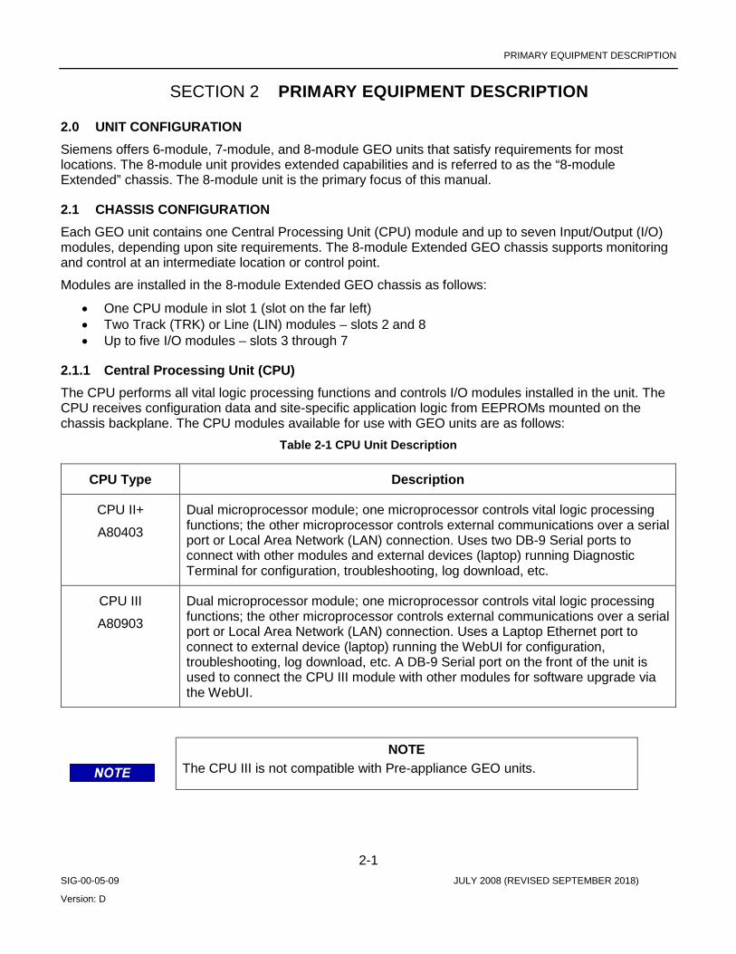
2.1.1 Central Processing Unit (CPU) The CPU performs all vital logic processing functions and controls I/O modules installed in the unit. The CPU receives configuration data and site-specific application logic from EEPROMs mounted on the chassis backplane. The CPU modules available for use with GEO units are as follows:
Table 2-1 CPU Unit Description
CPU Type Description
CPU II+
A80403
Dual microprocessor module; one microprocessor controls vital logic processing functions; the other microprocessor controls external communications over a serial port or Local Area Network (LAN) connection. Uses two DB-9 Serial ports to connect with other modules and external devices (laptop) running Diagnostic Terminal for configuration, troubleshooting, log download, etc.
CPU III
A80903
Dual microprocessor module; one microprocessor controls vital logic processing functions; the other microprocessor controls external communications over a serial port or Local Area Network (LAN) connection. Uses a Laptop Ethernet port to connect to external device (laptop) running the WebUI for configuration, troubleshooting, log download, etc. A DB-9 Serial port on the front of the unit is used to connect the CPU III module with other modules for software upgrade via the WebUI.
NOTE The CPU III is not compatible with Pre-appliance GEO units.

PRIMARY EQUIPMENT DESCRIPTION
2-2 SIG-00-05-09 JULY 2008 (REVISED SEPTEMBER 2018)
Version: D
2.1.2 I/O Modules Seven I/O modules are available to interface a GEO unit with wayside devices. These modules are listed below. See Chapter 3 in this manual, Primary Equipment Overview, for a complete description of each module.
Table 2-2 Module Description
Module Purposes
Track (TRK) Transmits and receives DC coded track messages through the tracks for one track circuit; compatible with Electro Code™ and Genrakode™ units. The track module also provides one VRO output. The VRO output typically provides cab rate signals.
Line (LIN) Transmits and receives DC coded track messages over cable (Line module to Line module) for one track circuit; compatible with Electro Code™ and Genrakode™ units. The Line module does not provide a VRO output.
Color Light Signal (CLS)
Controls and monitors six signal lamps; also receives two vital inputs and provides one vital output. In some applications, these inputs and outputs monitor and control switches.
Search Light Signal (SLS)
Controls and monitors two Search Light signal lamps and mechanisms; also receives two vital auxiliary inputs and provides one vital auxiliary output.
Relay Input/Output
(RIO)
Receives four inputs and provides four 12 VDC outputs; typically used to monitor and control switch machines.
NOTE Search Light Signal Modules are obsolete and no longer available.
2.2 END OF SIDING CONFIGURATION Complex locations such as end-of-sidings or double crossovers will use multiple GEO units. In existing installation, these units will be connected through the Echelon LAN twisted-pair interface. If new GEO locations are installed which use the CPU III, Ethernet can be used to link these via the Ethernet ports on the front of the CPU III modules and an Ethernet hub. Note that the SEAR2 and ULCP do not support Ethernet and must still be connected to the GEO using the Echelon LAN. If the GEO locations are not in the same bungalow so that the SEAR/ULCP cannot be connected to the GEO using the Echelon LAN, a WAG module is still required to support these.

PRIMARY EQUIPMENT DESCRIPTION
2-3 SIG-00-05-09 JULY 2008 (REVISED SEPTEMBER 2018)
Version: D
2.2.1 Simplified Block Diagram This simplified block diagram in Figure 2-1 is an example of a GEO unit for use in an intermediate or end-of-siding application. Not every GEO unit uses every GEO module. GEO unit configurations meet specific location requirements.
Figure 2-1 Simplified Block Diagram
Track Inductor
Central Processing
Unit
Color Light Signal
or
Search Light Signal
Vital Parallel Input
Module
Vital Relay Output Module
Relay Input/Output Module
Track/Line Module
Signals
Vital Input Devices
Vital Relays
Switch Machines
Track or wire line
Serial Ports and Echelon LAN
Interface I t f
External Communications
Diagnostic Port
Laptop Computer
Chassis ID Chip
External
Configuration
GEO chassis (within dotted line)

PRIMARY EQUIPMENT DESCRIPTION
2-4 SIG-00-05-09 JULY 2008 (REVISED SEPTEMBER 2018)
Version: D
2.3 HARDWARE IDENTIFICATION Figure 2-2 identifies the various major components of the GEO chassis.
Figure 2-2 GEO Chassis
2.4 APPLICATION LOGIC
2.4.1 Location Two EEPROMs mounted on the GEO backplane hold unit configuration and site-specific application logic.
LT
3 8ET 8T -
J2
PE
NFSU A
M20
T
-
CE PK
TARF 15
US
AM
J3 VROCOMMPORT -
+
R
9 22
Made in USA
1 10 1
5
34
67
6 5
87
34
54
67
B
AB
TRACK+J1 +
MF E
J5
910
J4
21
910
- TET
L3833 883
2910 1
54
6
87
5
34
67
29110
67
5
34
6
87
54
929
A53510
10 1 10
56
87
34
54
67
6
87
54
-
USEC
K
T FRA
P
15AM
J14 VRO -+
R
21
J6 J7
910
J8
910
21
J9 J10 J11 J12
1021
9 21
J13++
MF E
TRACK
Battery / LAN / Communications Interface
Track I Interface I/O Interface
Track 2 Interface
Slot 8 Track or LineModule (Optional)
Slot 3 - 7 I/OModules (Optional)
Slot 2: Track orLine Module(Optional)
ECD (MCFStored Here)
CIC (Site-SpecificInformation
Stored Here)
Slot 1: CPU Module

PRIMARY EQUIPMENT DESCRIPTION
2-5 SIG-00-05-09 JULY 2008 (REVISED SEPTEMBER 2018)
Version: D
• External Configuration Device (ECD) • Chassis ID Chip (CIC)
2.4.2 External Configuration Device (ECD) The External Configuration Device (ECD) is a memory module installed in a connector on the backplane. The ECD stores the Module Configuration File (MCF) for the GEO unit.
The MCF defines how the CPU and I/O modules interact to monitor and control signaling equipment. The MCF is loaded into the ECD at the factory, but can be modified during installation, if necessary.
2.4.3 Chassis ID Chip (CIC) The Chassis ID Chip (CIC) is a memory chip installed in a DIP socket on the backplane. The CIC stores the GEO unit configuration data, including site and module parameters.
2.4.4 Advantages Because the backplane includes all unit configuration and site-specific application logic, any module, including CPU modules (if the model is the same with the same software version), can be exchanged between GEO units without reconfiguring the unit or module.
NOTE When replacing a module, verify that the replacement module not only has identical hardware, but that the firmware version is also the same. Mismatched firmware results in boot errors (MCI errors) and the GEO not becoming fully operational. Avoid this possibility by keeping spare modules at up-to-date firmware version levels.
2.5 COLOR LIGHT SIGNAL CIRCUITS
2.5.1 Information Path Color light signals at a location connect to a Color Light Signal (CLS) module in a GEO unit. The CLS module responds to messages from the GEO CPU module by sending control voltages to the signals. The CLS monitors voltage and amperage levels to check signal status and sends this information to the CPU module. Based on these and other inputs, the CPU module uses site-specific programming to generate new command messages.
Each CLS module can control up to six lamps.
Inputs and outputs include:
• Six lamp outputs • One vital output • Two vital inputs • Red-retaining output (drops signal control relay in the event of a vital failure)

PRIMARY EQUIPMENT DESCRIPTION
2-6 SIG-00-05-09 JULY 2008 (REVISED SEPTEMBER 2018)
Version: D
2.5.2 Module Features Signal modules are designed to incorporate the following features:
• All inputs and outputs pass through opto-isolators that provide 2000 VAC surge protection for the module.
• Inductors mounted on each module provide additional surge suppression. • Input filters prevent AC voltages between 25 Hz and 220 Hz from energizing an input to the
module. • A DC-DC converter provides voltage stability and isolation for the current going to the signal
lamps. • LEDs on the module panel show the states of each input or output.
2.6 SEARCH LIGHT SIGNAL CIRCUITS
2.6.1 Information Path Search light signals at a location are connected to a Search Light Signal (SLS) module of a GEO unit. Each search light has red, yellow, and green check contacts. Each of these contacts is connected to an input on the SLS module. The SLS module sends control voltages to the lamps and signal mechanisms, and the GEO reads the signal mechanism contact position to determine signal status. The SLS module is controlled by the CPU.
Each SLS module controls two search light lamps and mechanisms.
Inputs and outputs include:
• Six signal position feedback inputs (three per signal mechanism) • Two auxiliary vital inputs • Two lamp outputs • Two signal mechanism outputs • One auxiliary vital output
2.6.2 Module Features Signal modules are designed to incorporate the following features:
• All inputs and outputs pass through opto-isolators that provide 2000 VAC surge protection for the module.
• Additional surge suppression is provided by inductors mounted on each module. • Inputs are filtered to provide AC frequency rejection. No external filters are required to prevent AC
voltages between 25 Hz and 220 Hz from energizing an input to the module.
2.7 INPUT/OUTPUT CIRCUITS
2.7.1 Information Path A Relay Input/Output (RIO) module allows a GEO to control and monitor an external device (typically a switch machine). The GEO CPU module generates command messages based on input data from I/O modules and site-specific programming. A RIO module responds to these command messages by setting specific voltages on its outputs to field equipment. The RIO module continuously monitors its outputs as well as inputs and sends status messages to the CPU module.
PRIMARY EQUIPMENT DESCRIPTION
2-7 SIG-00-05-09 JULY 2008 (REVISED SEPTEMBER 2018)
Version: D
Each RIO module provides four vital inputs and four vital outputs. Module outputs are controlled by the CPU and can be one of three types:
• Nominal voltage 12 VDC • Pulsed square-wave at one of five frequencies (used for cab signaling)
o 75 pulses per minute o 120 pulses per minute o 180 pulses per minute o 270 pulses per minute o 420 pulses per minute
• 60 cycles per minute flash – generally used to flash a local indicator
RIO modules often provide all inputs and outputs required to control switch operations, including electric locking.
2.7.2 Module Features RIO modules incorporate the following features:
• All inputs pass through opto-isolators that provide 2000 VAC surge protection for the module. • Input filters prevent AC voltages between 25 Hz and 220 Hz from energizing an input to the
module. • All outputs are transformer coupled to provide 2000 VAC surge protection for the module. • LEDs on the module indicate which inputs and outputs are energized.
2.8 TRACK CIRCUITS
2.8.1 Track Module Information Path Track modules transmit and receive DC coded track messages via the rails. Track modules receive DC coded messages and route them to the CPU for processing. The CPU generates commands based upon received messages and conditions at the site. Acting on CPU commands, the Track module transmits appropriate codes to the next wayside location.
Messages between the Track module and rails pass through track inductors mounted inside the GEO unit chassis. Each track module controls one track circuit.
See the Track Codes section of this chapter for information on message types.
2.8.1.1 Track Module Features Track modules incorporate the following features:
• Track circuit lengths can be up to 18,000 feet. • Two one-digit display units indicate which vital code is being transmitted and which vital code is
being received. • LEDs on the module indicate incoming/outgoing non-vital codes. • One Vital Relay Output, typically used for cab rate signaling. • One RS-232 Serial Port (DIAG) located on the front of the module can be used to download logs
from the module, or upload an MEF to the module with a laptop/personal computer.
PRIMARY EQUIPMENT DESCRIPTION
2-8 SIG-00-05-09 JULY 2008 (REVISED SEPTEMBER 2018)
Version: D
2.8.1.2 Line Module Information Path The GEO Line module is designed for a distributed/network application. It sends and receives DC-coded energy over wire cable. The Line module handles the transmit and receive functions for one end of a bidirectional line circuit. Line modules receive DC coded messages and route them to the CPU for processing. The CPU generates commands based upon received messages and conditions at the site. Acting on CPU commands, the Line module transmits appropriate codes to the Line module in the next wayside location.
Messages between Line modules pass through track inductors mounted inside the GEO unit chassis. Each Line module interfaces one track circuit.
See the Track Codes section of this chapter for information on message types.
2.8.1.3 Line Module Features Line modules incorporate the following features:
• Maximum cable length is 5 miles (8km) using #14 AWG or larger twisted pair wire. Note that maximum cable length depends on conditions such as type and size of wire or cable, and level of noise present.
• Two one-digit display units indicate which vital code is being transmitted and which vital code is being received.
• LEDs on the module indicate incoming/outgoing non-vital codes. • One RS-232 Serial Port (DIAG) located on the front of the module can be used to download logs
from the module, or upload an MEF to the module with a laptop/personal computer.
2.9 TRACK CODES
2.9.1 Purpose Track codes carry: track, block, and aspect information between two wayside locations. Ten track codes communicate this information. Six codes communicate vital information and four codes communicate non-vital information. Refer to the table on page 2-20 for typical code definitions.
2.9.1.1 Timing Defines Each Code Each code has a distinct timing characteristic. The Track/Line module transmits Code 1 every 2.5 seconds. This code provides a reference for all other code timing.
Other code pulses are transmitted at specific intervals following the Code 1 pulse. Timing between the Code 1 pulse and subsequent pulses determines the code(s) being transmitted.
Code 1 verifies track integrity when no other codes are being transmitted.
2.9.1.2 Vital Codes Vital codes carry aspect information. Only one vital code can be transmitted at a time.
Codes 2, 3, 4, 7, and 9 are defined by the railroad. Examples of code definitions are provided in the Table 2-3.
Code 8 is programmed for specific site requirements.

PRIMARY EQUIPMENT DESCRIPTION
2-9 SIG-00-05-09 JULY 2008 (REVISED SEPTEMBER 2018)
Version: D
2.9.1.3 Vital Code Timing Figure 2-3 shows the timing sequences used to communicate vital codes. Vital code pulses are generated at specific time intervals following the Code 1 reference pulse.
Figure 2-3 Vital Code Timing
2.9.1.4 Non-Vital Codes Non-vital codes can be transmitted along with the Code 1 pulse and vital code pulse. They are communicated by increasing the pulse width of the Code 1 pulse or the vital code pulse.
Codes 5 and 6 are predefined codes. Code M is a non-vital failure indication used to notify maintenance personnel of a situation requiring corrective action. Code M is programmed for specific site requirements.
An example of definitions for all codes is provided in Table 2-3.
224 ms
Codes 1 & 7
2.5 seconds
Code 1 Reference
332 msCodes 1 & 4
488 msCodes 1 & 3
692 ms
Codes 1 & 2
820 ms
Codes 1 & 9
948 ms
Codes 1 & 8

PRIMARY EQUIPMENT DESCRIPTION
2-10 SIG-00-05-09 JULY 2008 (REVISED SEPTEMBER 2018)
Version: D
Figure 2-4 Non-Vital Codes
2.10 SHUNTING When a train enters a block, its axles shunt the rails. The Track module at that location continues to transmit codes, but those codes are not received at the next location because of this shunting action.
The GEO unit interprets this loss of received codes as an indication that a train has entered the preceding block. Commands are generated to control devices at the GEO unit location, and codes are transmitted to the next location indicating occupancy of the preceding block.
2.10.1 Broken Rail Detection The GEO unit provides broken-rail detection in accordance with current FRA requirements. A rail break in a track circuit reduces track current in either direction.
NOTE Since Line Cards do not transmit track codes through the rails, broken rail detection is not provided by the GEO where Line Cards are used.
Within a track circuit, rail breaks can be located through visual inspection and voltage measurements.
2.10.1.1 Fail-Safe Operation If a vital failure is detected in a track circuit, signals for that track circuit are set to Stop.
Code 1 Reference
Code 1 & 5/M
Code 1 & 6
Codes 1 & 7
Code 1, 7, & 5/M

PRIMARY EQUIPMENT DESCRIPTION
2-11 SIG-00-05-09 JULY 2008 (REVISED SEPTEMBER 2018)
Version: D
2.10.1.2 Typical Track Code Definitions Table 2-3 provides typical definitions for vital and non-vital track codes.
Table 2-3 Track Code Definitions
Code Definition
1 Non-vital reference code that begins each message transmission Usually followed by other vital and non-vital codes Transmitted every 2.5 seconds Also used to verify track integrity when no other codes are being transmitted
2 Vital code indicating an approach aspect or medium approach
3 Vital code indicating an approach medium aspect or medium approach medium
4 Vital code indicating an approach limited or limited clear aspect
5 Non-vital code typically used to indicate block occupancy
6 Non-vital code typically used as a Tumbledown code to set opposing signals to stop
7 Vital code indicating a clear aspect
8 Vital code programmed for specific site requirements
9 Vital code indicating an approach slow aspect or medium approach slow
M Non-vital code used to indicate that a non-vital failure has occurred at the location Programmed for specific site requirements
2.11 DIAGNOSTIC PORT ON CPU II+
2.11.1 Information Path A 9-pin RS-232 port located on CPU II+ module provides a laptop computer connection to the unit.
GEO Diagnostic Terminal (DT) software communicates through the diagnostic port with the GEO module. DT software is provided on CD-ROM and can be loaded onto desktop or laptop personal computers (PCs) to perform installation, maintenance, and troubleshooting tasks.
Refer to the Siemens DT Field Handbook, document # SIG-00-04-17, for DT software use instructions.
2.12 LAPTOP PORT ON CPU III
2.12.1 Information Path An Ethernet Laptop port is located on the front of the CPU III module that provides either a network or direct laptop connection to the unit. The computer, running a web browser communicates with the built in web server on the CPU III. The WebUI is accessed via Firefox version 46.x, Internet Explorer 10 and 11, or Chrome version 55.x and can be used to perform installation, maintenance, and troubleshooting tasks. Refer to SIG-00-15-04 for further details.

PRIMARY EQUIPMENT DESCRIPTION
2-12 SIG-00-05-09 JULY 2008 (REVISED SEPTEMBER 2018)
Version: D
2.13 MAINTENANCE INTERFACE OF CPU A 4-character alphanumeric display unit and two push buttons located in the CPU module support basic maintenance and troubleshooting tasks when a laptop computer is unavailable.
2.13.1 Normal Operation During normal operation, the Module Configuration File (MCF) version number scrolls across the display unit from right to left. The MCF tells the CPU which modules to expect in the GEO unit.
On the CPU III: Using the Navigate (NAV) button, the user can scroll through two scrolling messages, MCF filename and IP address.
If a failure is detected, the display shows error messages instead of the MCF version number. Refer to Chapter 7 (Setup and Configuration Process) of this manual for a complete explanation of error messages.
2.14 VIEWING AND CHANGING SYSTEM SETTINGS ON THE CPU II+ The CPU II+ front panel has two push buttons allow for viewing and changing system settings. Pressing the Select (SEL) push button one time places the GEO unit in Menu mode. The module in slot 1 (CPU) is displayed. Pressing the Navigate (NAV) button moves down the menu to select slot 2 of the unit for configuration. Each successive press of the NAV button selects the next slot, from left to right, for configuration. To view parameters for a module slot, press the SEL push button. Parameters that can be viewed and changed vary with the type of module installed in the slot.
2.15 VIEWING AND CHANGING SYSTEM SETTINGS ON THE CPU III The CPU III front panel is equipped with a Select (SEL) and Navigate (NAV) that allows the user to access Program, Status, and Version menus on the CPU III four-character display. Using the NAV button, the user can toggle between the MCF version of the CPU III and the IP address. Pressing the SEL button will bring up the PROGRAM, STATUS, and VERSION menus. The user can navigate between them using the NAV button. SEL is used to select the desired menu, then NAV is used to scroll between the options. To select a menu option to complete, press SEL twice. To go back up a menu level, press NAV three times.
2.16 EXTERNAL COMMUNICATIONS GEO units equipped with either a CPU II+ (A80403) or CPU III (A80903) module can communicate with external devices. Communication between the GEO unit and external devices is established using an Advanced Train Control System (ATCS) messaging protocol.
The CPU II+ module supports two interfaces to external devices:
• Two RS-232 serial ports on the CPU II+ module • Echelon® Local Area Network (LAN) connection on the chassis
The CPU III module supports three interfaces to external devices
• One RS-232 DB-9 (male) serial port on the CPU III module • Echelon® Local Area Network (LAN) connection on the chassis • One Laptop Ethernet Port (RJ-45) on the CPU III module
Refer to site plans for communication connections at a specific location.
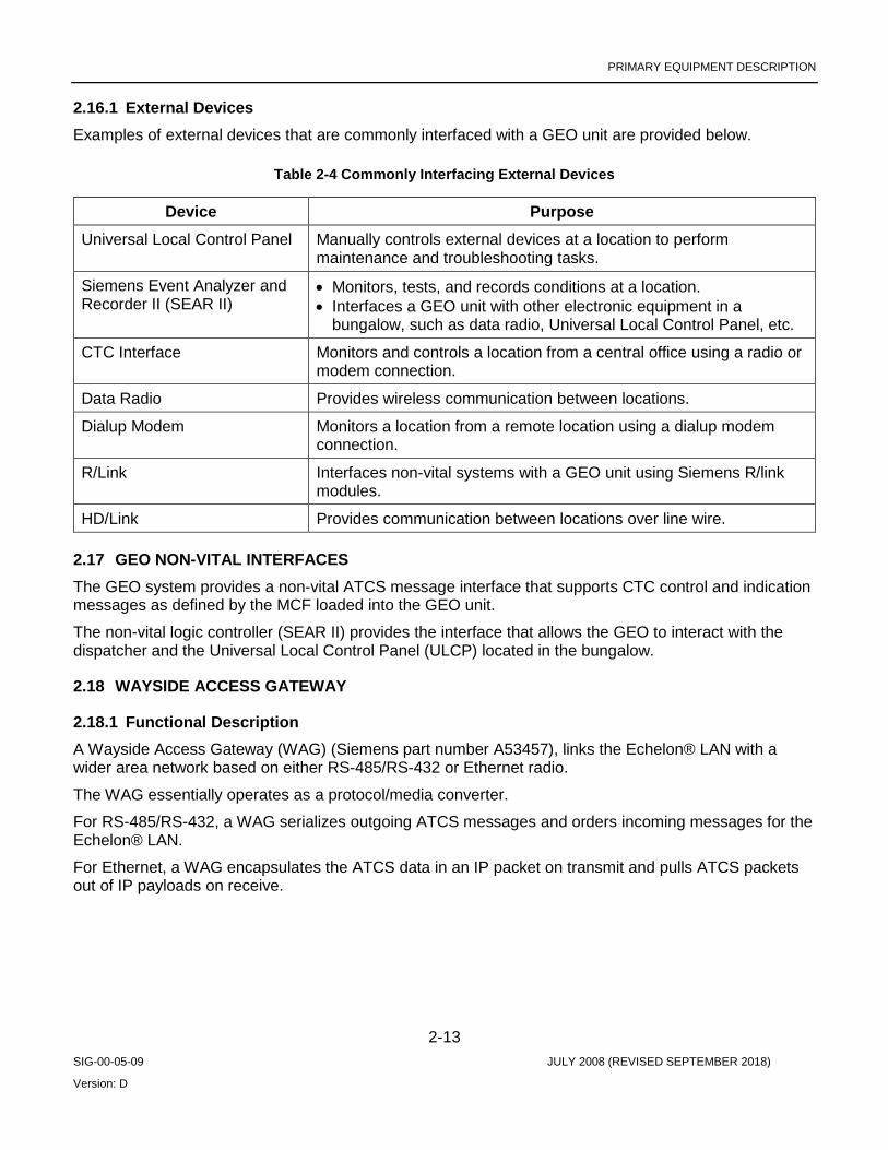
PRIMARY EQUIPMENT DESCRIPTION
2-13 SIG-00-05-09 JULY 2008 (REVISED SEPTEMBER 2018)
Version: D
2.16.1 External Devices Examples of external devices that are commonly interfaced with a GEO unit are provided below.
Table 2-4 Commonly Interfacing External Devices
Device Purpose Universal Local Control Panel Manually controls external devices at a location to perform
maintenance and troubleshooting tasks.
Siemens Event Analyzer and Recorder II (SEAR II)
• Monitors, tests, and records conditions at a location. • Interfaces a GEO unit with other electronic equipment in a
bungalow, such as data radio, Universal Local Control Panel, etc.
CTC Interface Monitors and controls a location from a central office using a radio or modem connection.
Data Radio Provides wireless communication between locations.
Dialup Modem Monitors a location from a remote location using a dialup modem connection.
R/Link Interfaces non-vital systems with a GEO unit using Siemens R/link modules.
HD/Link Provides communication between locations over line wire.
2.17 GEO NON-VITAL INTERFACES The GEO system provides a non-vital ATCS message interface that supports CTC control and indication messages as defined by the MCF loaded into the GEO unit.
The non-vital logic controller (SEAR II) provides the interface that allows the GEO to interact with the dispatcher and the Universal Local Control Panel (ULCP) located in the bungalow.
2.18 WAYSIDE ACCESS GATEWAY
2.18.1 Functional Description A Wayside Access Gateway (WAG) (Siemens part number A53457), links the Echelon® LAN with a wider area network based on either RS-485/RS-432 or Ethernet radio.
The WAG essentially operates as a protocol/media converter.
For RS-485/RS-432, a WAG serializes outgoing ATCS messages and orders incoming messages for the Echelon® LAN.
For Ethernet, a WAG encapsulates the ATCS data in an IP packet on transmit and pulls ATCS packets out of IP payloads on receive.

PRIMARY EQUIPMENT DESCRIPTION
2-14 SIG-00-05-09 JULY 2008 (REVISED SEPTEMBER 2018)
Version: D
This Page Intentionally Left Blank

EQUIPMENT INSTALLATION
3-1 SIG-00-05-09 JULY 2008 (REVISED SEPTEMBER 2018)
Version: D
SECTION 3 PRIMARY EQUIPMENT DESCRIPTION
3.0 PRIMARY EQUIPMENT OVERVIEW
3.1 CHASSIS DESCRIPTION The GEO chassis consists of the following components:
• Backplane (or motherboard) • External Configuration Device (ECD) • Chassis ID Chip (CIC) • Track inductors (for GEO units containing Track/Line modules) • Wiring terminal panel (not shown below, see Chapter 4.0)
CAUTION THE DEVICES DESCRIBED HERE MUST BE MOUNTED IN WEATHERPROOF ENCLOSURES UNLESS STATED OTHERWISE.
LT
3 8ET 8T -
J2
PE
NFSU A
M20
T
-
CE PK
TARF 15
US
AM
J3 VROCOMMPORT -
+
R
9 22
Made in USA
1 10 1
5
34
67
6 5
87
34
54
67
B
AB
TRACK+J1 +
MF E
J5
910
J4
21
910
- TET
L3833 883
2910 1
54
6
87
5
34
67
29110
67
5
34
6
87
54
929
A53510
10 1 10
56
87
34
54
67
6
87
54
-
USEC
K
TFRA
P
15AM
J14 VRO -+
R
21
J6 J7
910
J8
910
21
J9 J10 J11 J12
1021
9 21
J13++
MF E
TRACK
ECD
CIC

EQUIPMENT INSTALLATION
3-2 SIG-00-05-09 JULY 2008 (REVISED SEPTEMBER 2018)
Version: D
3.1.1 Backplane Each GEO unit contains a backplane located in the rear of the chassis. The backplane provides interconnections for modules installed in chassis slots and contains a serial bus that carries messages between the Central Processing Unit (CPU) and installed I/O modules.
Connections for the ECD and CIC are also located on the backplane.
WARNING THE CIC SHOULD NOT BE REMOVED OR REPLACED. IT CONTAINS VITAL SITE-SPECIFIC DATA REQUIRED FOR PROPER OPERATION OF THE SIGNALING SYSTEM.
3.1.2 Track Inductors Track inductors mounted in the rear of each chassis connect Track/Line modules to the track circuit. The primary purpose of the track inductors is lightning protection. There is one track inductor for each Track/Line module.
3.1.3 Central Processing Unit A Central Processing Unit (CPU) module is installed in slot 1 (the left most slot) of all GEO units. The The CPU performs all logic processing functions and controls Input/Output (I/O) modules installed in the unit.
3.1.4 Serial Bus Interface A serial bus on the chassis backplane carries messages between the CPU and I/O modules installed in the chassis. The CPU controls message flow on the serial bus and checks messages received from other modules for errors or omissions. If an error is detected, the CPU sets the suspect module to its most restrictive state.
3.1.5 System Clock The CPU module contains a real time clock that is accurate to within five minutes per year. The time and date can be set locally or remotely using any of the following methods:
• Maintainer Interface on the CPU module • Laptop computer interface • Remote connection over unit LAN, serial ports, or Network
3.1.6 Event Recording An event log on the CPU module records system events. Each event is time and date stamped. The event log is capable of recording approximately 3000 state changes on the CPU II+ and approximately 100,000 on the CPU III.
3.1.7 Power Supply The green POWER LED on the CPU module is on when battery voltage is applied to the unit.
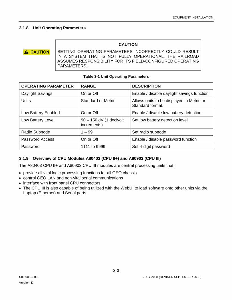
EQUIPMENT INSTALLATION
3-3 SIG-00-05-09 JULY 2008 (REVISED SEPTEMBER 2018)
Version: D
3.1.8 Unit Operating Parameters
CAUTION SETTING OPERATING PARAMETERS INCORRECTLY COULD RESULT IN A SYSTEM THAT IS NOT FULLY OPERATIONAL. THE RAILROAD ASSUMES RESPONSIBILITY FOR ITS FIELD-CONFIGURED OPERATING PARAMETERS.
Table 3-1 Unit Operating Parameters
OPERATING PARAMETER RANGE DESCRIPTION Daylight Savings On or Off Enable / disable daylight savings function
Units Standard or Metric Allows units to be displayed in Metric or Standard format.
Low Battery Enabled On or Off Enable / disable low battery detection
Low Battery Level 90 – 150 dV (1 decivolt increments)
Set low battery detection level
Radio Subnode 1 – 99 Set radio subnode
Password Access On or Off Enable / disable password function
Password 1111 to 9999 Set 4-digit password
3.1.9 Overview of CPU Modules A80403 (CPU II+) and A80903 (CPU III) The A80403 CPU II+ and A80903 CPU III modules are central processing units that:
• provide all vital logic processing functions for all GEO chassis • control GEO LAN and non-vital serial communications • interface with front panel CPU connectors • The CPU III is also capable of being utilized with the WebUI to load software onto other units via the
Laptop (Ethernet) and Serial ports.

EQUIPMENT INSTALLATION
3-4 SIG-00-05-09 JULY 2008 (REVISED SEPTEMBER 2018)
Version: D
3.1.9.1 CPU II+ Module User Interface The CPU II+ front panel is shown in Figure 3-1.
Figure 3-1 CPU II+ Front Panel
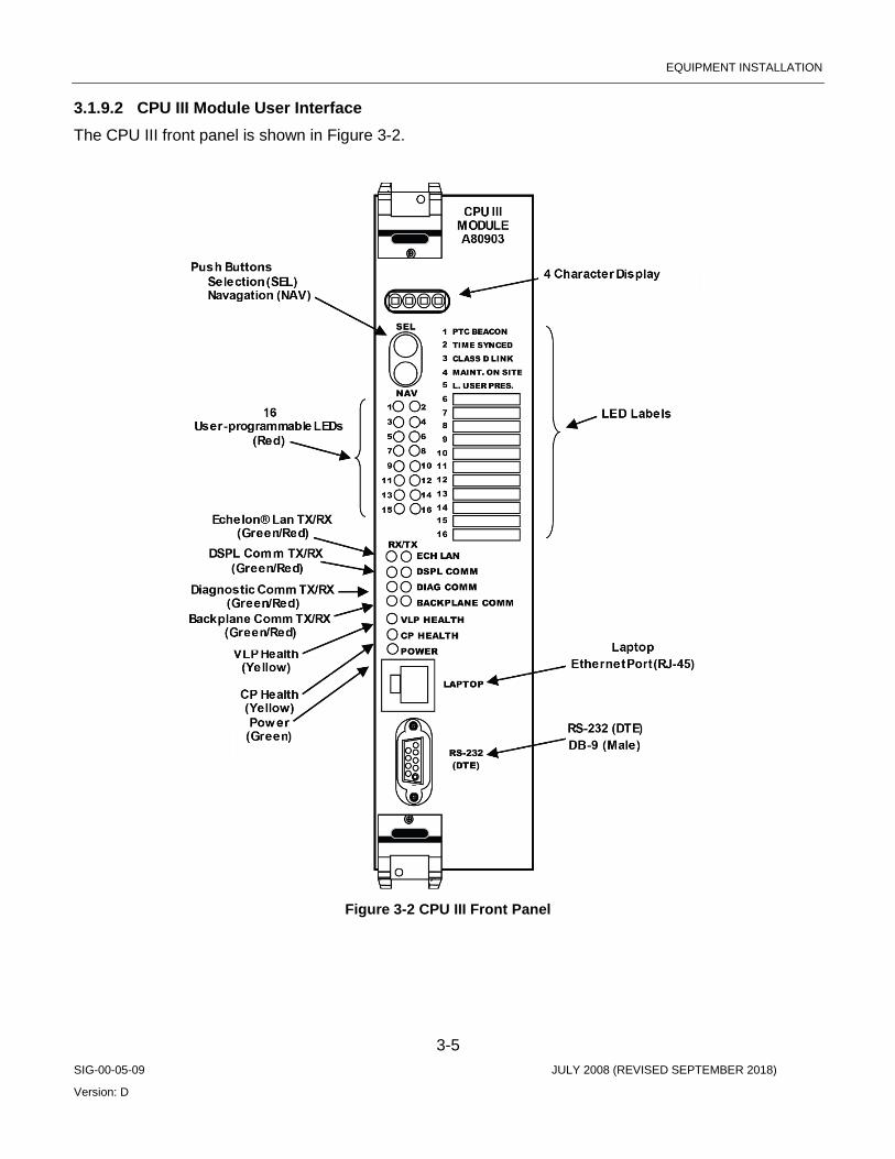
EQUIPMENT INSTALLATION
3-5 SIG-00-05-09 JULY 2008 (REVISED SEPTEMBER 2018)
Version: D
3.1.9.2 CPU III Module User Interface The CPU III front panel is shown in Figure 3-2.
Figure 3-2 CPU III Front Panel
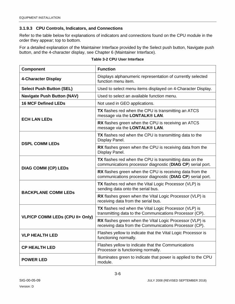
EQUIPMENT INSTALLATION
3-6 SIG-00-05-09 JULY 2008 (REVISED SEPTEMBER 2018)
Version: D
3.1.9.3 CPU Controls, Indicators, and Connections Refer to the table below for explanations of indicators and connections found on the CPU module in the order they appear; top to bottom.
For a detailed explanation of the Maintainer Interface provided by the Select push button, Navigate push button, and the 4-character display, see Chapter 6 (Maintainer Interface).
Table 3-2 CPU User Interface
Component Function
4-Character Display Displays alphanumeric representation of currently selected function menu item.
Select Push Button (SEL) Used to select menu items displayed on 4-Character Display.
Navigate Push Button (NAV) Used to select an available function menu.
16 MCF Defined LEDs Not used in GEO applications.
ECH LAN LEDs
TX flashes red when the CPU is transmitting an ATCS message via the LONTALK® LAN.
RX flashes green when the CPU is receiving an ATCS message via the LONTALK® LAN.
DSPL COMM LEDs
TX flashes red when the CPU is transmitting data to the Display Panel.
RX flashes green when the CPU is receiving data from the Display Panel.
DIAG COMM (CP) LEDs
TX flashes red when the CPU is transmitting data on the communications processor diagnostic (DIAG CP) serial port.
RX flashes green when the CPU is receiving data from the communications processor diagnostic (DIAG CP) serial port.
BACKPLANE COMM LEDs
TX flashes red when the Vital Logic Processor (VLP) is sending data onto the serial bus.
RX flashes green when the Vital Logic Processor (VLP) is receiving data from the serial bus.
VLP/CP COMM LEDs (CPU II+ Only)
TX flashes red when the Vital Logic Processor (VLP) is transmitting data to the Communications Processor (CP).
RX flashes green when the Vital Logic Processor (VLP) is receiving data from the Communications Processor (CP).
VLP HEALTH LED Flashes yellow to indicate that the Vital Logic Processor is functioning normally.
CP HEALTH LED Flashes yellow to indicate that the Communications Processor is functioning normally.
POWER LED Illuminates green to indicate that power is applied to the CPU module.

EQUIPMENT INSTALLATION
3-7 SIG-00-05-09 JULY 2008 (REVISED SEPTEMBER 2018)
Version: D
Component Function VLP Serial Port (CPU II+ Only) 9-pin diagnostic serial port for Vital Logic Processor.
DIAG (CP) Serial Port (CPU II+ Only)
9-pin diagnostic serial port for Communications Processor.
LAPTOP Port (CPU III Only) Ethernet port for WebUI access, or for communication via Ethernet cable from Display Laptop port.
RS-232 (DTE) (CPU III Only) 9-pin serial port for configuration management of modules via WebUI.
3.2 TRACK MODULE (A53285)
3.2.1 Overview Track modules transmit and receive DC coded track messages via the rails. Messages between the Track module and rails pass through track inductors mounted inside the GEO unit chassis. Each track module controls one end of a bi-directional coded track circuit. The Vital Relay Output on the Track module is typically used to transmit cab signals over the rails.
3.2.2 Output Parameters Output voltage is controlled by software. Track voltage can be set within a range of 0.00V to 4.00V in 0.1V increments. The Track module checks its output voltage during each code cycle. If the voltage is higher than the selected value, the transmitter is turned off.
Under failure conditions, the Track module is designed to prevent transmission of track codes. Only when it is commanded by the CPU can it transmit track codes.
3.2.3 Receive Current Receive current is adjusted by selecting different resistor values with a jumper located on the Track module. See Chapter 7.0, System Setup and Configuration, for an explanation of the receive current adjustment procedure.
3.2.4 Current Limiting LED Output current for each Track module can be set up to a limit of 10A. If current exceeds the selected current limit, the transmitter or receiver is turned off for that code cycle, and the RX or TX Current Limiting LED on the Track module is turned on momentarily.
If current exceeds the current limit for two consecutive code cycles, the transmitter or receiver is turned off and the Current Limiting LED is on steady.
3.2.5 Module Operating Parameters
CAUTION SETTING OPERATING PARAMETERS INCORRECTLY COULD RESULT IN A SYSTEM THAT IS NOT FULLY OPERATIONAL. THE RAILROAD ASSUMES RESPONSIBILITY FOR ITS FIELD-CONFIGURED OPERATING PARAMETERS.
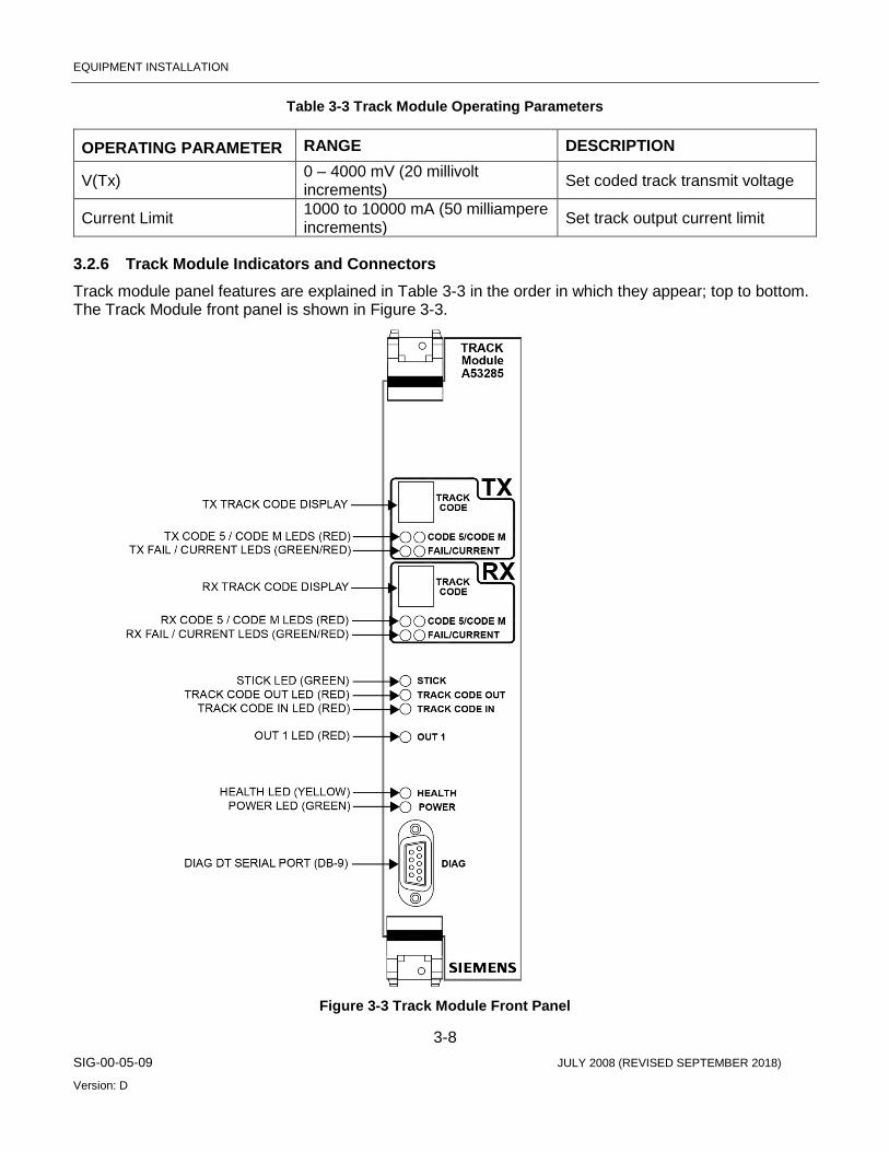
EQUIPMENT INSTALLATION
3-8 SIG-00-05-09 JULY 2008 (REVISED SEPTEMBER 2018)
Version: D
Table 3-3 Track Module Operating Parameters
OPERATING PARAMETER RANGE DESCRIPTION
V(Tx) 0 – 4000 mV (20 millivolt increments) Set coded track transmit voltage
Current Limit 1000 to 10000 mA (50 milliampere increments) Set track output current limit
3.2.6 Track Module Indicators and Connectors Track module panel features are explained in Table 3-3 in the order in which they appear; top to bottom. The Track Module front panel is shown in Figure 3-3.
Figure 3-3 Track Module Front Panel

EQUIPMENT INSTALLATION
3-9 SIG-00-05-09 JULY 2008 (REVISED SEPTEMBER 2018)
Version: D
Table 3-4 Track Module (A53285) Indicators and Connectors
Component Function
TX TRACK CODE Display
• Shows the vital code being transmitted. • Only one vital code transmitted in a code cycle. • Only vital codes are shown on this display. LEDs show the status of Code 5
and Code M messages. • Displays “d” when disabled. • Displays “E” during error condition. • Displays “F” during failure condition or fault. • A blank display indicates a module fault or that module is booting up.
TX CODE 5/ CODE M
LEDs (red/red)
TX CODE 5 LED:
• On - indicates transmission of Code 5 message.
TX CODE M LED:
• On - indicates transmission of Code M message.
TX FAIL/ CURRENT
LEDs (green/red)
TX FAIL LED:
• Flashing - indicates a Track condition fault. • On solid - indicates a Track module transmitter fault.
TX CURRENT LED:
• Flash rate proportional to transmission current. • Low current = long flash period. • High current = short flash period. • Current limiting = On. • Open track (current < 0.5 Amp) = Off.
RX TRACK CODE Display
• Displays the vital code that is being received. • Only one vital code received in each code cycle. • Only vital codes are shown on this display. LEDs show the status of Code 5
and Code M messages. • Displays “d” when disabled. • Displays “E” during error condition. • Displays “F” during failure condition. • A blank display indicates no code received.
RX CODE 5/ CODE M
LEDs (red/red)
RX CODE 5 LED:
• On - indicates a Code 5 message is being received.
RX CODE M LED:
• On - indicates a Code M message is being received.
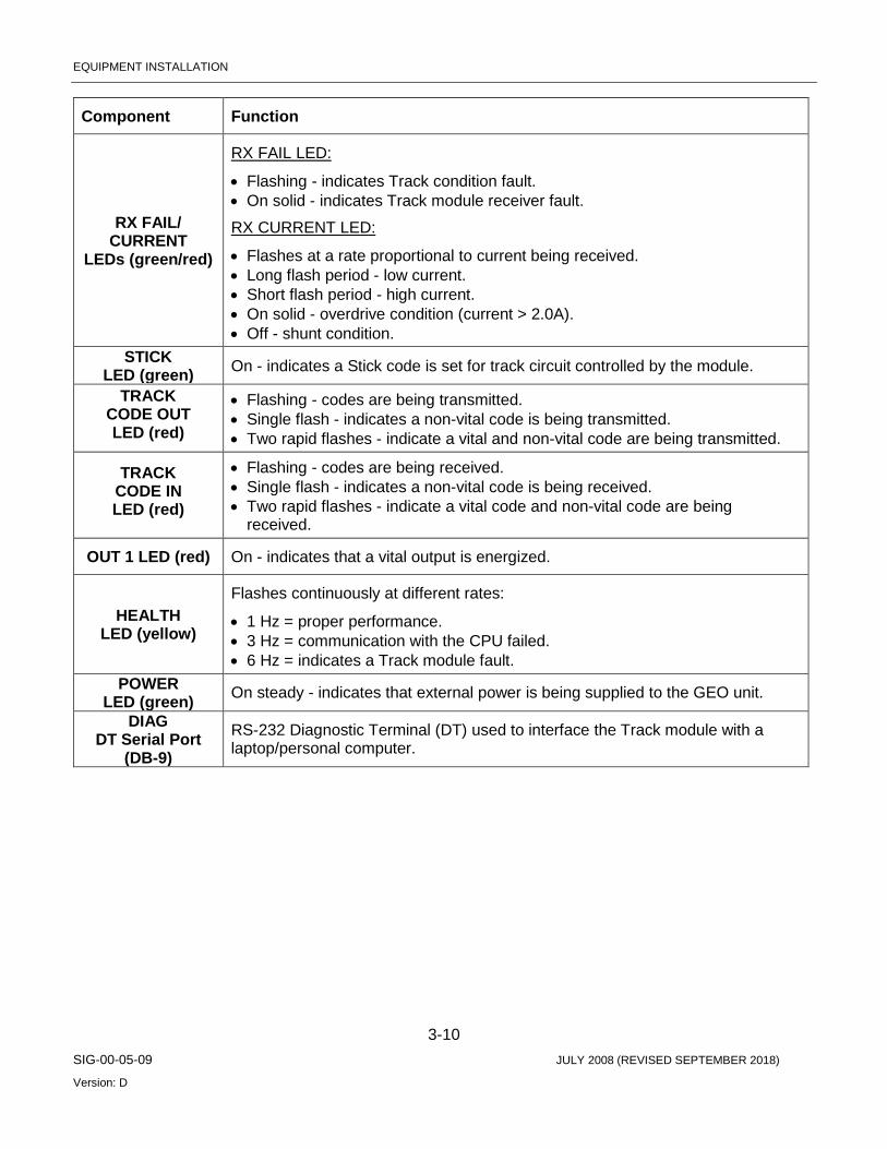
EQUIPMENT INSTALLATION
3-10 SIG-00-05-09 JULY 2008 (REVISED SEPTEMBER 2018)
Version: D
Component Function
RX FAIL/ CURRENT
LEDs (green/red)
RX FAIL LED:
• Flashing - indicates Track condition fault. • On solid - indicates Track module receiver fault.
RX CURRENT LED:
• Flashes at a rate proportional to current being received. • Long flash period - low current. • Short flash period - high current. • On solid - overdrive condition (current > 2.0A). • Off - shunt condition.
STICK LED (green) On - indicates a Stick code is set for track circuit controlled by the module.
TRACK CODE OUT LED (red)
• Flashing - codes are being transmitted. • Single flash - indicates a non-vital code is being transmitted. • Two rapid flashes - indicate a vital and non-vital code are being transmitted.
TRACK CODE IN LED (red)
• Flashing - codes are being received. • Single flash - indicates a non-vital code is being received. • Two rapid flashes - indicate a vital code and non-vital code are being
received.
OUT 1 LED (red) On - indicates that a vital output is energized.
HEALTH LED (yellow)
Flashes continuously at different rates:
• 1 Hz = proper performance. • 3 Hz = communication with the CPU failed. • 6 Hz = indicates a Track module fault.
POWER LED (green) On steady - indicates that external power is being supplied to the GEO unit.
DIAG DT Serial Port
(DB-9)
RS-232 Diagnostic Terminal (DT) used to interface the Track module with a laptop/personal computer.
EQUIPMENT INSTALLATION
3-11 SIG-00-05-09 JULY 2008 (REVISED SEPTEMBER 2018)
Version: D
3.3 LINE MODULE (A53254)
3.3.1 Overview The Coded Line Module is a special application card that transmits and receives DC coded track messages containing track, block and aspect information over wire cable. Wayside cable such as buried cable can be used instead of rail to send and receive track codes in cases where coded track circuits are impractical. The coded Line module is configured for the slot(s) normally configured with Track modules.
The Coded Line module transmits and receives track codes compatible with Electro Code® and Genrakode™. Each Coded Line module operates one end of a bidirectional coded line circuit.
On command from the CPU module, the Coded Line module transmits specific track codes and displays track codes on the Maintainer’s Interface. Under failure conditions, the Line module is designed to prevent transmission of track codes. Only when it is commanded by the CPU can it transmit codes.
The Line module receives track codes which are then decoded. After decoding the codes, it sets bits in the status message sent to the CPU module. If the code is not present, a bit cannot be set in the status message.
3.3.2 Shorted Line Detection If the Coded Line module detects a transmit current greater than 800 mA (due to a shorted line, etc.), the SHORTED LINE DETECT LED on the Line module lights, but the transmitter does not shut off. As soon as the output current drops below 800 mA, the SHORTED LINE DETECT LED extinguishes.
3.3.3 Module Operating Parameters The Line module transmit voltage (VTX) and receive threshold (VRX) can be set within a range of 2.00 to 15.00 VDC by using either the Maintainer’s Interface, the Diagnostic Terminal (CPU II+) or the WebUI (CPU III).
CAUTION SETTING OPERATING PARAMETERS INCORRECTLY COULD RESULT IN A SYSTEM THAT IS NOT FULLY OPERATIONAL. THE RAILROAD ASSUMES RESPONSIBILITY FOR ITS FIELD-CONFIGURED OPERATING PARAMETERS.
Table 3-5 Line Module Operating Parameters
OPERATING PARAMETER RANGE DESCRIPTION
VTX 2.00 VDC to 15.00 VDC (0.10 volt increments)
Set coded line transmit voltage
VRX 2.00 VDC to 15.00 VDC (0.10 volt increments)
Set line receive threshold
EQUIPMENT INSTALLATION
3-12 SIG-00-05-09 JULY 2008 (REVISED SEPTEMBER 2018)
Version: D
3.3.4 External Filtering Each Coded Line module interfaces with its line circuit through inductors mounted in the rear of the GEO chassis. External filtering to improve noise rejection can be applied to the Coded Line modules through connection to the AREMA terminals on the I/O panel marked “EXT FLTR”.
The Line module can generate vital and non-vital track codes as follows:
• Vital codes = 2, 3, 4, 7, 8, and 9 • Non-vital codes = 1, 5, 6, and M
Each code has a distinct timing characteristic and performs a specific job in the signal control system. Code 1 is used for track information. Code 5 is a non-vital code. Code 6 is used for tumble-down, and is a single pulse with a width of 600 msec. Code M can be used as a non-vital maintenance code.
3.3.5 Event Recording The Coded Line module maintains a time-stamped and dated event log for recording its own functional events. Coded Line module events are also logged in the CPU module event log (stored in the CPU module non-volatile memory), because it is in communication with the CPU module. Any of the event logs may be viewed by using the DT if CPU II+ is used, or the WebUI is a CPU III module is in use. The DT and WebUI provides tools for navigating the log, filtering and presenting data, printing, etc. For example, filters may be selected to view only module Operating Parameter changes.
Because of the limited storage capabilities for the internal event recorder, the system supports different levels of event recording, known as verbosity levels. Verbosity level 1 is the most general and level 5 the most detailed. The verbosity level for recording events can be viewed and set by using the DT utility or WebUI.

EQUIPMENT INSTALLATION
3-13 SIG-00-05-09 JULY 2008 (REVISED SEPTEMBER 2018)
Version: D
3.3.6 Line Module Indicators and Connectors Line module panel (Maintainer’s Interface) features are explained in the following table in the order in which they appear on the module; top to bottom. The Line Module LEDs and Display is shown in Figure 3-4.
Figure 3-4 Line Module LEDs and Display

EQUIPMENT INSTALLATION
3-14 SIG-00-05-09 JULY 2008 (REVISED SEPTEMBER 2018)
Version: D
Table 3-6 Line Module (A53254) Indicators and Connectors
Component Function
CODE TX Display (green)
• Shows the vital code being transmitted. • Only one vital code transmitted in a code cycle. • Only vital codes are shown on this display. LEDs show the status of
Code 5 and Code M messages. • Displays “d” when disabled. • Displays “E” during error condition. • Displays “F” during failure condition or fault. • A blank display indicates a module fault or that module is booting up.
CODE 5 TX / CODE M TX
LEDs (red/red)
CODE 5 TX LED: • On - indicates transmission of Code 5 message. CODE M TX LED: • On - indicates transmission of Code M message.
TX SHORTED LINE
DETECT / UNDEFINED
LEDs (green/red)
SHORTED LINE DETECT LED: • On solid - indicates a Line module transmitter fault. UNDEFINED LED: • Not used
CODE RX Display (red)
• Displays the vital code that is being received. • Only one vital code received in each code cycle. • Only vital codes are shown on this display. LEDs show the status of
Code 5 and Code M messages. • Displays “d” when disabled. • Displays “E” during error condition. • Displays “F” during failure condition. • A blank display indicates no code received.
CODE 5 RX / CODE M RX
LEDs (red/red)RX
CODE 5 RX LED: • On - indicates a Code 5 message is being received. CODE M RX LED: • On - indicates a Code M message is being received.
UNDEFINED LEDs (green/red)
UNDEFINED LED: • Not used UNDEFINED LED: • Not used
DT Serial Port (DIAG) (DB-9)
RS-232 Diagnostic Terminal (DT) used to download logs from the Line module, or upload an MEF to the Line module with a laptop/personal computer.
STICK LED (red)
• On - indicates a Stick code is set for track circuit controlled by the module.

EQUIPMENT INSTALLATION
3-15 SIG-00-05-09 JULY 2008 (REVISED SEPTEMBER 2018)
Version: D
Component Function
CODE OUT LED (red)
• Flashing - codes are being transmitted. • Single flash - indicates a non-vital code is being transmitted. • Two rapid flashes - indicate a vital and non-vital code are being
transmitted.
CODE IN LED (red)
• Flashing - codes are being received. • Single flash - indicates a non-vital code is being received. • Two rapid flashes - indicate a vital code and non-vital code are being
received.
HEALTH LED (yellow)
Flashes continuously at different rates: • 1 Hz = proper performance. • 3 Hz = communication with the CPU failed. • 6 Hz = indicates a Line module fault.
3.4 COLOR LIGHT SIGNAL MODULE (A53284)
3.4.1 Overview The CPU module in a GEO controls the Color Light Signal (CLS) module. The CLS module in turn controls two color light heads (six lamps).
As an optional module, the CLS can be installed in slots 3 – 7, depending on site requirements.
Inputs and outputs include:
• Six lamp outputs • One vital auxiliary output • Two vital auxiliary inputs • Red-retaining output (controls Signal-Stop relay coil)
3.4.2 Lamp Outputs Lamp output voltage is adjustable through system software. Voltage can be adjusted from 9.0 to 13.0 VDC in increments of 1 mV. No external lamp resistor is required.
Lamp output (Voltage Regulation) can be programmed via the DT or WebUI as either constant or variable. Variable will dynamically reduce the input current requirement and extend battery life. To use the variable parameter the CLS MEF must be CLS01_13 or later, the module must be an A53284, and the GEO application program must be compiled with Hardware Description file version 20 (HWDESC020) or later (included with GCS 2.4.5 or later).
CLS module outputs turn signal lamps on or off or flash signal lamps. If it is required to flash lamps in synchronization, the lamps must be controlled by the same CLS module.
3.4.3 Filament Checks The CLS module tests each lamp to determine if the filament is intact and whether the lamp is on. If the lamp is determined to be on or flashing when not commanded to be, the CPU commands the CLS module to turn off all the lamps it controls. This is to prevent foreign energy from affecting lamps.
EQUIPMENT INSTALLATION
3-16 SIG-00-05-09 JULY 2008 (REVISED SEPTEMBER 2018)
Version: D
3.4.4 Foreign Energy Detection If a lamp is being energized from a source other than the GEO system, the CLS module detects the condition during its lamp filament check cycle and turns off the lamps.
After the lamps are turned off, the CLS module rechecks the lines to see if the voltage is still present. If the other voltage source is still present, the CPU module reports the condition as a Foreign Energy (FEN) fault.
3.4.5 Red Retaining Relay Function The CLS module supports the Red-Retaining Relay function which is used to set all associated block signals to red in the event a malfunction is detected on the CLS module or a problem is detected with the associated block signal lamp circuit.
Each CLS module in the GEO case can be assigned a Red-Retaining Relay output.
All CLS modules in a single GEO case (up to four modules) can also be grouped in various combinations that use a common Red-Retaining Relay output assigned to one module in the group. A maximum of three groups is possible in a single GEO case.
The Red-Retaining Relay assignment and group assignments are made using the GEO Diagnostic Terminal software.
3.4.6 Red Retaining Relay Operation (Single CLS Module) If a single CLS module is assigned a Red-Retaining Relay output and a malfunction is detected on that module or in the associated block signal lamp circuit, the module turns off its on-board converter and deenergizes the Red-Retaining Relay output. The CPU module will see that the module is down and attempt to turn the module converter back on every 20 seconds. If the problem still exists, the converter will remain off.
When the Red-Retaining Relay output on the affected CLS module is deenergized, the relay contacts disconnect all associated yellow and green block signal lamp circuits. This condition supplies a lamp out indication for the affected block signal(s) to a CTC system at a central office.
The CPU status log and the status log for this CLS module will indicate the general type of malfunction.
3.4.7 Red Retaining Relay Operation (CLS Module Group) When two or more (up to four) CLS modules in a single GEO case are grouped for the Red-Retaining Relay function, one module in the group is assigned the Red-Retaining Relay output.
Scenario #1:
If a malfunction is detected on the module assigned the Red-retaining Relay output, or in the block signal lamp circuit associated with that module, only that module will turn off its on-board converter and deenergize the Red-Retaining Relay output. When the Red-Retaining Relay output is deenergized, the relay contacts disconnect all yellow and green block signal lamp circuits associated with the group. This will in turn cause an error on the remaining CLS modules in the group and they will turn off their respective converters. This condition supplies a lamp out indication for the affected block signal(s) to a CTC system at a central office.

EQUIPMENT INSTALLATION
3-17 SIG-00-05-09 JULY 2008 (REVISED SEPTEMBER 2018)
Version: D
The CPU module will attempt to turn the module converters back on every 20 seconds. If the problem still exists, the converters will remain off.
Scenario #2:
If a malfunction is detected on a CLS module in the group that is not assigned the Red-Retaining Relay output, or in the block signal lamp circuit associated with that module, that module will turn off its on-board converter. The CPU module will see that the module is down and command all other CLS modules in the group to turn off their converters. This action will deenergize the Red-Retaining Relay output for the group. When the Red-Retaining Relay output is deenergized, the relay contacts disconnect all yellow and green block signal lamp circuits associated with the group. This condition supplies lamp out indications for the affected block signal(s) to a CTC system at a central office.
The CPU will attempt to turn the module converters back on every 20 seconds. If the problem still exists, the converters will remain off.
The CPU status log and the status log for each CLS module in the group will indicate the general type of malfunction. Pay close attention to the first failure report for the CLS module group in the CPU status log as this will most likely indicate the module or associated circuitry that caused the problem.
3.4.8 Red Retaining Relay Operation (mixing modules with old and new MEFs)
WARNING MIXING CLS MODULES WITH OLDER MEFS INSTALLED AND CLS MODULES WITH NEWER MEFS INSTALLED IN THE SAME GEO CASE MAY DISABLE THE RED-RETAINING RELAY FUNCTION AND PREVENT CERTAIN CLS MODULES FROM GOING INTO SESSION.
If CLS modules running early MEFs (prior to cls01_10.mef) are mixed with CLS modules running the latest MEF (cls01_10.mef and later) in the same GEO case, and Red-Retaining options are set, the older modules will not go into session when power is applied to the system. The older MEFs do not support the Red-Retaining Relay function or grouping and the converters on these modules will be turned off by the CPU. Only the modules with the newer MEF will remain operational.
If CLS modules running early MEFs (prior to cls01_10.mef) are mixed with CLS modules running the latest MEF (cls01_10.mef and later) in the same GEO case, and Red-Retaining options are NOT set, all modules will go into session when power is applied to the system.
3.4.9 Module Operating Parameters
CAUTION SETTING OPERATING PARAMETERS INCORRECTLY COULD RESULT IN A SYSTEM THAT IS NOT FULLY OPERATIONAL. THE RAILROAD ASSUMES RESPONSIBILITY FOR ITS FIELD-CONFIGURED OPERATING PARAMETERS.

EQUIPMENT INSTALLATION
3-18 SIG-00-05-09 JULY 2008 (REVISED SEPTEMBER 2018)
Version: D
Table 3-7 Color Light Signal Operating Parameters
OPERATING PARAMETER RANGE DESCRIPTION
Lamp Voltage 9000 – 13000 mV (1 millivolt increments) Set lamp voltage
Filament Threshold
150 – 2500 mA (10 milliampere increments)
Sets lamp filament threshold for light out detection. NOTE: Should be left at default. If change is required, consult Siemens Technical Support.
VPI Debounce 20 – 200 ms (2 millisecond increments) Set VPI debounce time
Lamp Voltage Regulation Constant or Variable
Set to Constant to maintain constant lamp output voltage even under low battery conditions. For details see previous “Lamp Outputs” section.
3.4.10 CLS Indicators and Connectors Indicators and connectors on the CLS module are described in Table 3-7. The Color Light Signal Module front panel is shown in Figure 3-5.

EQUIPMENT INSTALLATION
3-19 SIG-00-05-09 JULY 2008 (REVISED SEPTEMBER 2018)
Version: D
Figure 3-5 Color Light Signal Front Panel

EQUIPMENT INSTALLATION
3-20 SIG-00-05-09 JULY 2008 (REVISED SEPTEMBER 2018)
Version: D
Table 3-8 Color Light Signal Module (A53284) Indicators and Connectors
Component Function
LAMP 1-6 LEDs (red) On / Off / Flashing (aspect indication).On - associated lamp output is energized.
IN 1-2 LEDs (red) On = associated vital input is energized.
OUT 1 LED (red) On steady for an energized vital output, or flashes at 60Hz to indicate a 60Hz flash rate or a cab signal output.
HEALTH LED (yellow)
Flashes continuously at different rates: • 1 Hz = proper performance • 3 Hz = communication with the CPU failed • 6 Hz = indicates a CLS module fault
POWER LED (green) On steady - indicates that external power is being supplied to the GEO unit.
DIAG DT Serial Port (DB-9) RS-232 Diagnostic Terminal (DT) used to interface the Color Light module with a laptop/personal computer.
3.5 SLS MODULE (A53263)
3.5.1 Overview Search light signals at a location are connected to a Search Light Signal (SLS) module of a GEO unit. The red, yellow, and green check contacts of each search light are connected to inputs on the SLS module. The SLS module sends control voltages to the lamps and signal mechanisms, and feedback is sent from the signals to the CPU through the SLS module to indicate signal status.
The SLS module is controlled by the CPU. As an optional module, the SLS may be installed in slots 3 – 7, depending on site requirements.
NOTE Inputs and outputs include:
• Six signal position feedback inputs (vital, if rev A or later). • Two lamp outputs. • Two signal mechanism outputs. • Two auxiliary vital inputs. • One auxiliary vital output.

EQUIPMENT INSTALLATION
3-21 SIG-00-05-09 JULY 2008 (REVISED SEPTEMBER 2018)
Version: D
3.5.2 Lamp Outputs Lamp output voltage is adjustable through system software. Voltage can be adjusted from 9.0 to 13.0 VDC in increments of 1 mV. No external lamp resistor is required.
Lamp output (Voltage Regulation) can be programmed via the DT or WebUI as either constant or variable. Variable will dynamically reduce the input current requirement and extend battery life. To use the variable parameter the SLS MEF must be SLS01_01 or later, the module must be rev A or later, and the GEO application program must be compiled with Hardware Description file version 20 (HWDESC020) or later (included with GCS 2.4.5 or later).
SLS module outputs control signal mechanism positioning, turns signal lamps on or off, or flashes signal lamps. If it is required to flash lamps in synchronization, the lamps must be controlled by the same SLS module.
3.5.3 Filament Checks The SLS module tests each lamp to determine if the filament is intact and whether the lamp is on. If the lamp is determined to be on or flashing when not commanded to be, the CPU commands the SLS module to turn off all the lamps it controls. This is to prevent foreign energy from affecting the lamp.
3.5.4 Foreign Energy Detection If a lamp is being energized from a source other than the GEO system, the SLS module detects the condition during its lamp filament check cycle, and turns off the lamps as if a short were present.
After the lamps are turned off, the SLS module rechecks the lines to see if the voltage is still present. If the other voltage source is still present, the CPU module reports the condition as a Foreign Energy (FEN) fault.

EQUIPMENT INSTALLATION
3-22 SIG-00-05-09 JULY 2008 (REVISED SEPTEMBER 2018)
Version: D
3.5.5 Search Light Signal (SLS) Indicators and Connectors Indicators and connectors on the SLS module are described in Table 3-8. The Search Light Signal Module front panel is shown in Figure 3-6.
NOTE Search Light Signal (SLS) Modules are obsolete and no longer available for purchase from Siemens.
Figure 3-6 Search Light Signal Front Panel
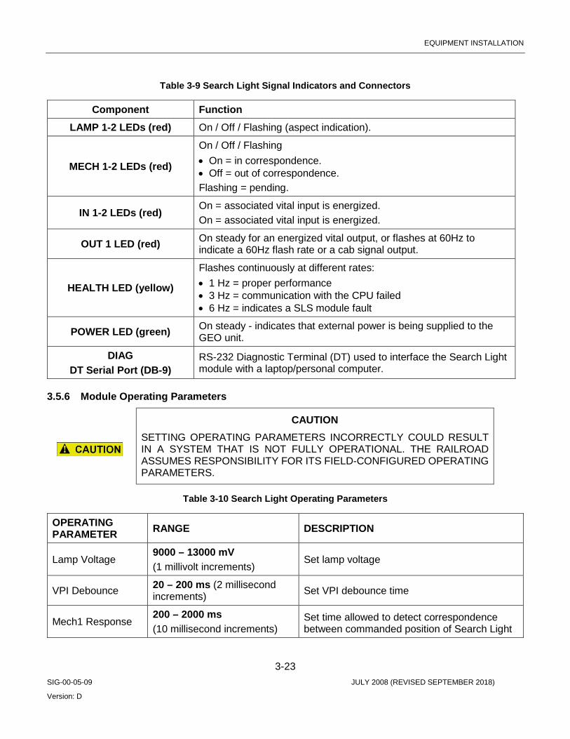
EQUIPMENT INSTALLATION
3-23 SIG-00-05-09 JULY 2008 (REVISED SEPTEMBER 2018)
Version: D
Table 3-9 Search Light Signal Indicators and Connectors
Component Function LAMP 1-2 LEDs (red) On / Off / Flashing (aspect indication).
MECH 1-2 LEDs (red)
On / Off / Flashing • On = in correspondence. • Off = out of correspondence. Flashing = pending.
IN 1-2 LEDs (red) On = associated vital input is energized. On = associated vital input is energized.
OUT 1 LED (red) On steady for an energized vital output, or flashes at 60Hz to indicate a 60Hz flash rate or a cab signal output.
HEALTH LED (yellow)
Flashes continuously at different rates: • 1 Hz = proper performance • 3 Hz = communication with the CPU failed • 6 Hz = indicates a SLS module fault
POWER LED (green) On steady - indicates that external power is being supplied to the GEO unit.
DIAG DT Serial Port (DB-9)
RS-232 Diagnostic Terminal (DT) used to interface the Search Light module with a laptop/personal computer.
3.5.6 Module Operating Parameters
CAUTION SETTING OPERATING PARAMETERS INCORRECTLY COULD RESULT IN A SYSTEM THAT IS NOT FULLY OPERATIONAL. THE RAILROAD ASSUMES RESPONSIBILITY FOR ITS FIELD-CONFIGURED OPERATING PARAMETERS.
Table 3-10 Search Light Operating Parameters
OPERATING PARAMETER RANGE DESCRIPTION
Lamp Voltage 9000 – 13000 mV (1 millivolt increments)
Set lamp voltage
VPI Debounce 20 – 200 ms (2 millisecond increments) Set VPI debounce time
Mech1 Response 200 – 2000 ms (10 millisecond increments)
Set time allowed to detect correspondence between commanded position of Search Light
EQUIPMENT INSTALLATION
3-24 SIG-00-05-09 JULY 2008 (REVISED SEPTEMBER 2018)
Version: D
OPERATING PARAMETER RANGE DESCRIPTION
300 – 3000 ms (15 millisecond increments)
mechanism 1 and current position, before declaring mechanism failed.
Mech2 Response
200 – 2000 ms (10 millisecond increments) Set correspondence detect time for Search
Light mechanism 2 (see above). 300 – 3000 ms (15 millisecond increments)
Lamp Voltage Regulation Constant or Variable
Set to Constant to maintain lamp output voltage, even under low battery conditions. For details see previous “Lamp Outputs” section.
3.6 RIO MODULE (A80413)
3.6.1 Overview Relay Input/Output (RIO) modules are used to control and monitor an external device (typically a switch machine). Output commands are routed through the RIO module to the external device, and device status information is sent to the CPU through the RIO module.
As an optional module, the RIO can be installed in slots 3 – 7, depending on site requirements.
In the course of controlling switches, RIO modules often control electric lock circuits.
Each RIO module can provide up to four vital inputs and four vital outputs. Module outputs are controlled by the CPU and can be one of three types:
Constant voltage 12 VDC
Square-wave coding at one of five frequencies (used for cab signaling)
• 75 pulses per minute • 120 pulses per minute • 180 pulses per minute • 270 pulses per minute • 420 pulses per minute • 60 cycles per minute (1 Hz) flash – generally used to flash a local indicator
LEDs on the module light to indicate which inputs and outputs are energized.
3.6.2 Input Parameters Relay contacts are used in the input circuitry. Input voltages of 7.5 volts or greater are recognized as energized. Input voltages of less than 2.5 volts are recognized as de-energized.
Inputs, up to a maximum of 65 VAC, are filtered to reject AC frequencies between 25Hz and 220Hz and prevent these AC voltages from energizing inputs.
All inputs to a RIO module pass through opto-isolators that provide 2000 VAC surge protection for the module.

EQUIPMENT INSTALLATION
3-25 SIG-00-05-09 JULY 2008 (REVISED SEPTEMBER 2018)
Version: D
The Vital Parallel Input (VPI) debounce delay time specifies the amount of time an input must remain constant to be considered a valid input. Debounce prevents random spikes of electrical energy from energizing the input.
3.6.3 Output Parameters The RIO module tests its outputs and reports their states to the CPU module for diagnostic purposes. If the RIO module detects that an output has failed, it shuts that output down and retries it every five seconds. RIO outputs are transformer coupled to provide 2000 VAC surge protection for the module.
CAUTION SETTING OPERATING PARAMETERS INCORRECTLY COULD RESULT IN A SYSTEM THAT IS NOT FULLY OPERATIONAL. THE RAILROAD ASSUMES RESPONSIBILITY FOR ITS FIELD-CONFIGURED OPERATING PARAMETERS.
Table 3-11 RIO Operating Parameters
OPERATING PARAMETER RANGE DESCRIPTION VPI Debounce 20 – 200 ms (2 millisecond increments) Set VPI debounce time
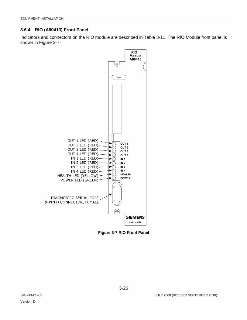
EQUIPMENT INSTALLATION
3-26 SIG-00-05-09 JULY 2008 (REVISED SEPTEMBER 2018)
Version: D
3.6.4 RIO (A80413) Front Panel Indicators and connectors on the RIO module are described in Table 3-11. The RIO Module front panel is shown in Figure 3-7.
Figure 3-7 RIO Front Panel

EQUIPMENT INSTALLATION
3-27 SIG-00-05-09 JULY 2008 (REVISED SEPTEMBER 2018)
Version: D
Table 3-12 RIO Indicators and Connectors
Component Function
OUT 1-4 LEDs (red) On steady – associated vital output is energized, or flash at 60 Hz to indicate a 60 Hz flash rate or a cab rate.
IN 1-4 LEDs (red) On - associated vital input is energized.
HEALTH LED (yellow)
Flashes continuously at different rates: • 1 Hz = proper performance. • 3 Hz = communication with the CPU failed. • 6 Hz = indicates a RIO module fault.
POWER LED (green) On steady - indicates that external power is being supplied to the GEO unit.
DIAG Serial Port (DB-9)
RS-232 Diagnostic Terminal (DT) used to interface the RIO module with a laptop/personal computer.

EQUIPMENT INSTALLATION
4-28 SIG-00-05-09 JULY 2008 (REVISED SEPTEMBER 2018)
Version: D
SECTION 4 AUXILIARY EQUIPMENT OVERVIEW
4.0 UNIVERSAL LOCAL CONTROL PANEL (ULCP) A50692
4.1.1 Overview The ULCP can be used to view and control the operation of the system from the bungalow. The ULCP is customized for a specific application with a printed overlay positioned on an LED array to create a track status display. The ULCP includes a minimum of logic and depends on application files running on the SEAR II.
Major ULCP features include:
• Display of status indications for up to seven parallel sections of track and interconnecting switches
• Field-configurable with replaceable track configuration overlays • 1.2 Mb/s client LAN port for communication with other wayside equipment • Alarms and non-vital I/O
For further information, refer to the ‘Universal Local Control Panel (ULCP) Installation & Operation Manual’ (Siemens document number SIG-00-01-23).
4.1.2 Front Panels The ULCP consists of a programmable array of LEDs and push buttons. The functions of the controls, indicators and connectors on the ULCP are described on the next page.
Figure 4-1 Universal Local Control Panel (ULCP) Front Panel

EQUIPMENT INSTALLATION
4-29 SIG-00-05-09 JULY 2008 (REVISED SEPTEMBER 2018)
Version: D
4.1.3 Controls and Indicators The system-level controls and indicators are located on the left side of the ULCP as shown below.
Application-level controls and indicators for a ULCP in an end-of-siding application are shown in the example on page 3-38.
Figure 4-2 Universal Local Control Panel Controls and Indicators
EQUIPMENT INSTALLATION
4-30 SIG-00-05-09 JULY 2008 (REVISED SEPTEMBER 2018)
Version: D
4.1.4 System Level Controls For control locations, refer to the Figure 4-2.
Table 4-1 ULCP Controls
Component Function
Echelon Push button Pushing this button causes the ULCP to send an ID message over the Echelon LAN. This supports LAN setup.
REMOTE / LOCAL / FIELD Switch
Either a toggle switch or a key switch. Remote – Instructions from a central location control the ULCP in this mode Local – The ULCP is controlled by the GEO CPU responding to push button controls on the ULCP front panel. This mode allows the maintainer to exercise field equipment from the bungalow. Field – For future use.
ON / OFF / TEST Switch OFF – ULCP de-energized. HEALTH and POWER LEDs continue to function. ON – ULCP is energized. All push buttons and LEDs function as described. TEST – All LEDs light to show that they are functional.
4.1.5 System Level Indicators For indicator locations, refer to the figure on the previous page. These indictors function regardless of the position of the REMOTE/LOCAL/FILED switch. In general, application-level controls and indictors function only when the ULCP is set for LOCAL control.
Table 4-2 ULCP Indicators
Component Function RX / TX / SERVICE
LEDs On - indicates incoming (RX) or outgoing (TX) Echelon traffic or, for the SERVICE LED, when the ULCP puts an ID message on the LAN. Echelon ID messages support interfacing equipment to the LAN.
HEALTH LED Flashing at 1 Hz - indicates the ULCP is working properly with the SEAR II. Off - contact with SEAR II has been lost.
POWER On steady - indicates power applied to ULCP.
Buzzer Audible alarm signal.
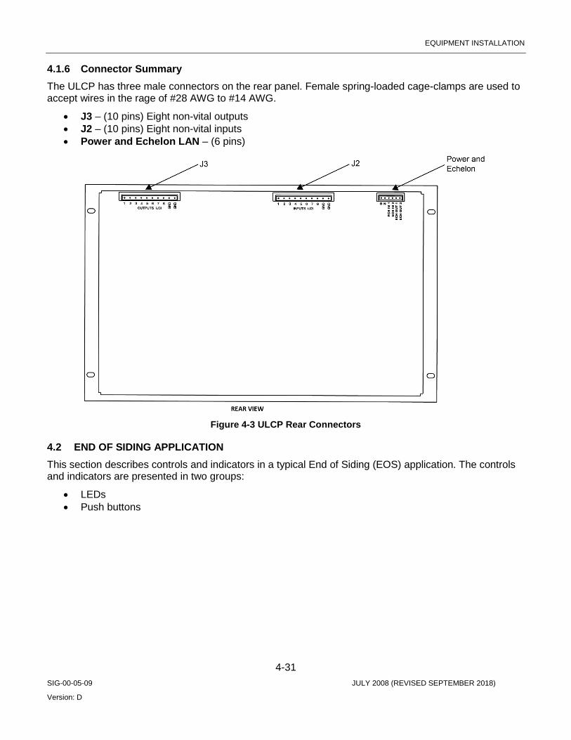
EQUIPMENT INSTALLATION
4-31 SIG-00-05-09 JULY 2008 (REVISED SEPTEMBER 2018)
Version: D
4.1.6 Connector Summary The ULCP has three male connectors on the rear panel. Female spring-loaded cage-clamps are used to accept wires in the rage of #28 AWG to #14 AWG.
• J3 – (10 pins) Eight non-vital outputs • J2 – (10 pins) Eight non-vital inputs • Power and Echelon LAN – (6 pins)
Figure 4-3 ULCP Rear Connectors
4.2 END OF SIDING APPLICATION This section describes controls and indicators in a typical End of Siding (EOS) application. The controls and indicators are presented in two groups:
• LEDs • Push buttons
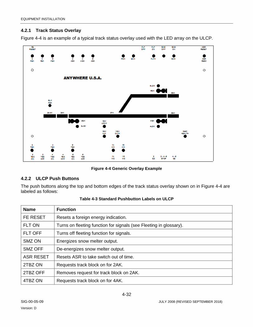
EQUIPMENT INSTALLATION
4-32 SIG-00-05-09 JULY 2008 (REVISED SEPTEMBER 2018)
Version: D
4.2.1 Track Status Overlay Figure 4-4 is an example of a typical track status overlay used with the LED array on the ULCP.
Figure 4-4 Generic Overlay Example
4.2.2 ULCP Push Buttons The push buttons along the top and bottom edges of the track status overlay shown on in Figure 4-4 are labeled as follows:
Table 4-3 Standard Pushbutton Labels on ULCP
Name Function FE RESET Resets a foreign energy indication.
FLT ON Turns on fleeting function for signals (see Fleeting in glossary).
FLT OFF Turns off fleeting function for signals.
SMZ ON Energizes snow melter output.
SMZ OFF De-energizes snow melter output.
ASR RESET Resets ASR to take switch out of time.
2TBZ ON Requests track block on for 2AK.
2TBZ OFF Removes request for track block on 2AK.
4TBZ ON Requests track block on for 4AK.
EQUIPMENT INSTALLATION
4-33 SIG-00-05-09 JULY 2008 (REVISED SEPTEMBER 2018)
Version: D
Name Function 4TBZ OFF Removes request for track block on 4AK.
6TBZ ON Requests track block on for 6AK.
6TBZ OFF Removes requests for track block on 6AK.
1NWZ Requests #1 switch normal.
1RWZ Requests #1 switch reverse.
2GZ Requests #2 signal to ‘line up’.
2-4-6 STOP Commands a ‘lined-up’ signal to stop.
4-6GZ Requests #4 or #6 signal to ‘line-up’ depending on switch position.
4.2.3 ULCP LEDs LEDs labeled in the track status overlay are defined as follows:
Table 4-4 Standard LED Labels on ULCP
Name Function 2FEK 4FEK 6FEK
On red - when foreign energy is detected at signals 2, 4, or 6. These indicators stay latched on until the FE RESET button is pushed.
2ASK 4ASK 6ASK
Normally on red Off - when a signal is lined or running time.
POK Normally off On red – when AC power to location is off.
ECK Normally off On red – under following conditions: • Dispatcher requests maintainer call • Switch is in correspondence but switch control relay back check input is low.
FLTK Normally off On red - when fleeting is turned on.
SMK Normally off On red - indicates snow melter on.
ASR RESK Normally OFF On red - when ASR RESET button is pushed.
2TBK 4TBK 6TBK
Normally off Flashing red - when track 2, 4, or 6 is requested. Solid red - when track 2, 4, or 6 block is in.

EQUIPMENT INSTALLATION
4-34 SIG-00-05-09 JULY 2008 (REVISED SEPTEMBER 2018)
Version: D
1NWK Flashing red - switch is requested normal and is not in correspondence, or switch is in correspondence and the switch control relay back check input is low. Solid red - indicates switch has normal correspondence.
1RWK Flashing red - switch is requested reverse and is not in correspondence, or when switch is in correspondence and the switch control relay back check input is low. Solid red – indicates switch has reverse correspondence.
1SW LOCK Normally off On - when switch is locked.
1SW NJK Normally off On - when switch in hand throw (M23 only).
1SW OLTK Normally off On red - when switch overload timer has run.
2GK 4GK 6GK
Signal status: • Solid green – signal cleared. • Flashing green – signal not cleared. • Sold red – signal at stop. • Flashing red – signal in time.
2LOK 4LOK 6LOK
Normally off Solid red – light out indication from signal 2, 4, or 6.
BLK POK Normally off Solid yellow - when maintenance codes are not received on #2 track.
2AAK Normally off Solid yellow - when Code 5 is not received on #2 track.
2AK 4AK 6AK
Normally off Solid red - when Code 1 is not received on track 2, 4, or 6.
2TK Normally off Solid red - when OS track circuit is de-energized.
GEO HEALTH
Normally solid yellow Flashing yellow - when communication between ULCP and SEAR and/or GEO is lost.
For further information regarding the Universal Local Control Panel, please reference manual SIG-00-01-24.

EQUIPMENT INSTALLATION
4-35 SIG-00-05-09 JULY 2008 (REVISED SEPTEMBER 2018)
Version: D
4.3 SIEMENS EVENT ANALYZER AND RECORDER II (SEAR II)
4.3.1 Overview The SEAR II provides recording, reporting of automated testing, and monitoring functions.
The basic SEAR II system configuration (standalone recorder with no expansion modules) features:
• Up to 23 separate input functions. • Internal temperature and internal battery sensor functions. • 2 internal non-vital relays. • A local user interface for field programming. • Battery backed event recorder.
The SEAR II uses the Echelon LAN to communicate with expansion modules:
• Analog Input Module for four analog inputs. • Analog/Digital I/O Module for 30 input functions (24 external digital inputs, 4 external analog inputs,
and internal temperature and internal battery sensor functions) and 4 digital outputs. • SDIM and SDIMFE modules allow digital inputs to be added in increments of 24, up to 120.
4.3.2 SEAR II Operation in an EOS In an end of siding (EOS) application, the SEAR II monitors communications over the Echelon LAN from the GEO unit, data radio, and Universal Local Control Panel, along with direct inputs from field equipment and other sensors. Based on these inputs, the SEAR II maintains an event log.
Like all other devices on an Echelon LAN, the SEAR II has a peer-to-peer relationship with other devices on the LAN. The SEAR II can play a role routing messages between other devices at the outside network, but it does not play a control or routing role on the LAN.
According to site-specific application programming, the SEAR II provides the intelligence behind the ULCP. SEAR II application programming can send alarms or other messages to the CTC or direct automated testing of the location to meet FRA requirements.
For further information, refer to ‘Siemens Event Analyzer and Recorder (SEAR II) Installation & Operation Manual’ (Siemens document number SIG-00-02-07).
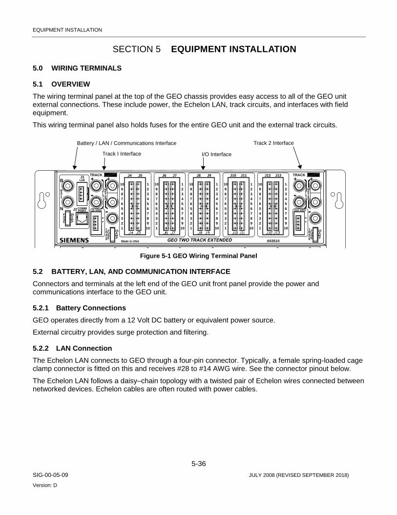
EQUIPMENT INSTALLATION
5-36 SIG-00-05-09 JULY 2008 (REVISED SEPTEMBER 2018)
Version: D
SECTION 5 EQUIPMENT INSTALLATION
5.0 WIRING TERMINALS
5.1 OVERVIEW The wiring terminal panel at the top of the GEO chassis provides easy access to all of the GEO unit external connections. These include power, the Echelon LAN, track circuits, and interfaces with field equipment.
This wiring terminal panel also holds fuses for the entire GEO unit and the external track circuits.
Figure 5-1 GEO Wiring Terminal Panel
5.2 BATTERY, LAN, AND COMMUNICATION INTERFACE Connectors and terminals at the left end of the GEO unit front panel provide the power and communications interface to the GEO unit.
5.2.1 Battery Connections GEO operates directly from a 12 Volt DC battery or equivalent power source.
External circuitry provides surge protection and filtering.
5.2.2 LAN Connection The Echelon LAN connects to GEO through a four-pin connector. Typically, a female spring-loaded cage clamp connector is fitted on this and receives #28 to #14 AWG wire. See the connector pinout below.
The Echelon LAN follows a daisy–chain topology with a twisted pair of Echelon wires connected between networked devices. Echelon cables are often routed with power cables.
LT
3 8ET 8T -
J2
PE
NFSU A
M20
T
-
CE PK
TARF 15
US
AM
J3 VROCOMMPORT -
+
R
9 22
Made in USA
1 10 1
5
34
67
6 5
87
34
54
67
B
AB
TRACK+J1 +
MF E
J5
910
J4
21
910
- TET
L3833 883
2910 1
54
6
87
5
34
67
29110
67
5
34
6
87
54
929
A53510
10 1 10
56
87
34
54
67
6
87
54
-
USEC
K
T FRA
P
15AM
J14 VRO -+
R
21
J6 J7
910
J8
910
21
J9 J10 J11 J12
1021
9 21
J13++
MF E
TRACK
Battery / LAN / Communications Interface
Track I Interface I/O Interface
Track 2 Interface

EQUIPMENT INSTALLATION
5-37 SIG-00-05-09 JULY 2008 (REVISED SEPTEMBER 2018)
Version: D
The Echelon connections are arbitrary, that is, the wire from ECH 0 on one Echelon device can be connected to ECH 0 or ECH 1 on the next device.
5.2.3 Fuse A 30 AMP fuse protects GEO from internal short circuits and external power surges.
5.3 TRACK AND I/O CONNECTORS AND FUSES
5.3.1 Overview The wiring terminal panel includes separate areas for the connectors and fuses supporting the Track/Line module in slot 2 (Track 1 I/O) and the Track/Line module in slot 8 (Track 2). These identical areas each include:
• Terminals for the track circuit (one also serves as a meter terminal) • Two meter terminals supporting measurement of track current • Two filter terminals • Four-pin VRO connector • 15 A Fuse
5.3.2 Meter Terminals These two terminals allow the track current from a module to be routed through a meter for a precise measurement of current.
5.3.3 Track VRO This connector supports the auxiliary output available on the Track modules. Only the top two pins are used. Observe proper polarity. This output typically drives cab signals.
5.3.4 Track Fuse This 15 A fuse protects the Track/Line module from over-current conditions typically caused by track signal cables shorting to one another or high voltages on the rails.
This automotive style fuse can be inspected through the transparent plastic fuse body or by simply pulling it out of the socket.
Pin # Name Description
1 ECH 0 Echelon conductor
2 ECH 1 Echelon conductor
3
N/A
twisted pair
N/A
4

EQUIPMENT INSTALLATION
5-38 SIG-00-05-09 JULY 2008 (REVISED SEPTEMBER 2018)
Version: D
5.3.5 External Surge Protection The simplified schematic below shows surge protection circuitry between the GEO and the rails. A surge suppression panel holds the equalizers and air gap arresters that provide primary protection against lighting strikes and other high energy conditions.
5.3.6 External Filtering A low-pass filter screens out unwanted signals and noise from the Track/Line card input.
As shown in the following simplified schematic, if an external filter module is used, it connects to the filter terminals to put it in parallel with the track. Observe proper polarity.
Figure 5-2 GEO External Filtering
+Track Codes
Low PassFilter Module
SurgeProtector
Low-Pass Filter Circuitry
To tracks+
To GEO unit- +
- -

EQUIPMENT INSTALLATION
5-39 SIG-00-05-09 JULY 2008 (REVISED SEPTEMBER 2018)
Version: D
5.4 I/O CONNECTORS FOR OPTIONAL MODULES
5.4.1 Overview The GEO Wiring Terminals include 5 pairs of 10-pin connectors (J4 – J13). These connect the I/O modules in slots 3 through 7 with field equipment.
Figure 5-3 Wiring Slots 1 Through 7
5.4.2 Typical Connector Pair Pinouts I/O connector pin assignments for CLS, SLS, RIO, VPI and VRO modules follow:
CLS SLS RIO CLS SLS RIO
VRO+ LAMP CNTL 1+ VRO 1+ LAMP 3+ A HEAD+ VPI 2+
VRO- LAMP CNTL 1- VRO 1- LAMP 3- A HEAD- VPI 2-
VPI 1+ LAMP CNTL 2+ VRO 2+ LAMP 4+ B HEAD+ VPI 3+
VPI 1- LAMP CNTL 2- VRO 2- LAMP 4- B HEAD- VPI 3-
VPI 2+ VRO+ VRO 3+ LAMP 5+ GREEN VPI 4+
VPI 2- VRO- VRO 3- LAMP 5- YELLOW VPI 4-
LAMP 1+ VPI 1+ VRO 4+ LAMP 6+ RED (n/a)
LAMP 1- VPI 1- VRO 4- LAMP 6- GREEN (n/a)
LAMP 2+ VPI 2+ VPI 1+ RED RETAINING + YELLOW (n/a)
LAMP 2- VPI 2- VPI 1- RED RETAINING- RED (n/a)
Slot 3 Slot 4 Slot 5 Slot 6 Slot 7

EQUIPMENT INSTALLATION
5-40 SIG-00-05-09 JULY 2008 (REVISED SEPTEMBER 2018)
Version: D
VPI VRO VPI VRO
VPI 1+ VRO 1+ VPI 6+ VRO 6+
VPI 1- VRO 1- VPI 6- VRO 6-
VPI 2+ VRO 2+ VPI 7+ (n/a)
VPI 2- VRO 2- VPI 7- (n/a)
VPI 3+ VRO 3+ VPI 8+ (n/a)
VPI 3- VRO 3- VPI 8- (n/a)
VPI 4+ VRO 4+ Analog Input 1+ (n/a)
VPI 4- VRO 4- Analog Input 1- (n/a)
VPI 5+ VRO 5+ Analog Input 2+ (n/a)
VPI 5- VRO 5- Analog Input 2- (n/a)
5.5 INSTALLATION OVERVIEW
5.5.1 Process Perform the following tasks to install a GEO unit:
1. Ensure DC offsets, wideband shunts and old DC track circuits have been removed. 2. Check bungalow for physical/electrical defects. 3. Install the GEO chassis per location circuit plans. 4. Connect wiring to external devices. 5. Apply power and observe the system startup sequence.
5.5.2 Test Equipment and Tools The following test equipment and tools are required to perform the installation procedure:
• Digital voltmeter • Common hand tools • Computer with Diagnostic Terminal Software (CPU II+ Only)or Internet Browser (WebUI, CPU III Only)
5.5.3 Wiring and Configuration Settings Tasks listed here are for sample installation procedures only. Refer to site plans at the location for specific wiring connections and software configuration settings.

EQUIPMENT INSTALLATION
5-41 SIG-00-05-09 JULY 2008 (REVISED SEPTEMBER 2018)
Version: D
5.5.4 ESD Precautions Electrostatic discharge (ESD) can damage electronic circuitry, particularly low voltage components found on GEO modules. Therefore, Siemens encourages its customers to adopt the following procedures to lessen the likelihood of equipment damage in the field due to ESD:
• Ground yourself before touching card cages, modules, or components. • Remove modules from chassis by the ejector lever only. • Handle circuit boards by the edges only. • Never physically touch the circuit board contact fingers or allow these fingers to come in contact
with an insulator (e.g., plastic, rubber, etc.). • When not in use, place circuit boards in approved static-shielding bags, contact fingers first.
Remove circuit boards from static-shielding bags by grasping the ejector lever or the edge of the board only. Each bag should include a caution label on the outside indicating static-sensitive contents.
• Cover workbench surfaces used for repair of electronic equipment with static dissipative workbench matting.
• Utilize only anti-static cushioning material in equipment shipping and storage containers.
5.5.5 Check for DC Offsets and Wideband Shunts
WARNING
THE GEO SYSTEM REQUIRES THAT DC OFFSETS BE ELIMINATED AND WIDE BAND SHUNTS REPLACED WITH NARROW BAND SHUNTS.
5.5.6 Definition of DC Offset DC offset refers to a voltage on the rails when the track circuit is disconnected.
5.5.7 Procedure Follow this procedure to ensure there are no DC offsets or wide band shunts on the track circuits.
1. Verify that previously installed batteries for DC track circuits have been disconnected from the track circuit.
2. Measure rail to rail voltage across the track to ensure that no DC offsets is present. 3. If DC offsets are present without track batteries connected the source must be determined
and the offsets eliminated. 4. Recheck the voltage across the track for DC offsets. 5. Check for wide band shunts installed in the track circuits. If wide band shunts are installed in
the track circuits, replace them with narrow band shunts.

EQUIPMENT INSTALLATION
5-42 SIG-00-05-09 JULY 2008 (REVISED SEPTEMBER 2018)
Version: D
5.6 BUNGALOW CHECKS
5.6.1 Procedure Follow this procedure to ensure conditions in the bungalow are satisfactory for system installation.
1. Ensure adequate ventilation is present and that any installed ventilation fans are functioning properly.
2. Check for loose, corroded, or oxidized wire connections and terminals. 3. Test the bungalow ground per railroad recommended procedures 4. Check the physical condition of the bungalow. Check for:
• Proper door alignment and sealing • Openings that would allow dust, rain or rodents to enter • Clogged door ventilation filters
5. Ensure adequate room is available in the bungalow to allow access to the front and back of the GEO unit following installation.
6. Check site plans for additional AC power and battery requirements. Install as necessary. See Note 1.
NOTE The GEO chassis requires only one power feed for all functions. This single power feed supplies all of the energy to operate the GEO hardware/system as well as illuminate all the lamp loads, operate the GEO track circuit and power any other external load (relays, etc.) driven by the GEO system. This single power feed replaces multiple power feeds used by similar equipment and therefore must be sized to handle the current demands. Additionally, the GEO color light and search light modules have a DC/DC converter built in that is user settable. This converter maintains a constant output voltage over a range of battery voltages. This constant voltage allows the brightness of the lamps to be held constant as the battery voltage varies. However, as the battery voltage decreases the converter must draw more current in order to maintain the constant power output. This results in the current load per illuminated incandescent lamp to rise above the nominal values one normally expects. A typical GEO system can draw 2.0 - 4.0 amps steady state with no lamps lit to18.0 – 22.0 amps with (6) six lamps lit when powered from a fully charged battery supply system. Therefore, for GEO to reliably maintain these constant output voltages it is critical that the DC power source used to power GEO is properly designed and maintained.
EQUIPMENT INSTALLATION
5-43 SIG-00-05-09 JULY 2008 (REVISED SEPTEMBER 2018)
Version: D
5.7 INSTALL CHASSIS
5.7.1 Procedure Follow this procedure to install the GEO chassis.
7. Mount the GEO chassis in a location that provides access to the front and back of the chassis, and prevents dirt, debris, and rain from contacting the unit when the bungalow door is opened.
8. Mount the GEO chassis in a rack assembly or on a level surface. 9. Ensure modules are mounted in the correct slots of the chassis and are properly seated. Refer to
site plans for proper module placement. 10. Install a battery surge protection panel between the battery and battery connections on the GEO
chassis. Siemens supplies surge panels for use with GEO units 11. Install additional arresters and equalizers, as necessary.
CAUTION SIEMENS RECOMMENDS THE USE OF PRIMARY ARRESTERS AND EQUALIZERS ON VPI, VRO, ANALOG, AND TRACK EXTERNAL LINES. LAMP OUTPUTS SHOULD HAVE PRIMARY ARRESTERS ONLY. EQUALIZERS SHOULD NOT BE CONNECTED ACROSS SIGNAL LAMP PAIRS.
5.7.2 Connect Wiring for External Devices 5.7.3 Plug-In Circuit Modules Each plug-in circuit module is equipped with:
• dual 43-pin connector on one edge which plugs into a corresponding edge connector on the motherboard
• locking ejector levers at the top and bottom of each module to facilitate removal from the case
5.7.4 External Wiring Connectors and Wire Size All external wiring to a GEO Assembly is by means of plug-in connectors.
The orange cage-clamp connectors for the signal circuits should use 16 to 12 AWG wire.
The orange cage-clamp connector for the LONTALK® LAN (Echelon®) should use communication grade twisted wires of at least 20 AWG. Refer to Echelon manual (COM-00-07-09) for further information.
NOTE Generic spare connectors that are not keyed for specific modules may be ordered. Refer to the catalog for ordering information.

EQUIPMENT INSTALLATION
5-44 SIG-00-05-09 JULY 2008 (REVISED SEPTEMBER 2018)
Version: D
5.7.5 Wire Preparation Strip insulation from the end of the wire as follows:
Connector Type Strip Length Screw terminal 0.28” (7 mm)
Cage clamp 0.32” – 0.35” (8-9 mm)
NOTE Use a stripping tool to accurately set the strip length. The addition of ferrules is not required.
5.7.6 Screw-terminal Connector Wire Insertion Wires are secured to the screw-terminal connector as follows:
1. Insert the stripped end of a wire into the wire receptor of the connector until it stops
2. Tighten the screw to a torque of 4.5 inch pounds (0.508 Newton meters)
5.7.7 Cage-Clamp Connector Wire Insertion Wires are secured to the cage-clamp connector as follows:
1. Place a flat bladed screwdriver in the rectangular slot in the connector next to the wire receptor (see figure below).
2. Use a screwdriver blade 0.10 in. wide and 0.020 in. thick (2.5mm x 0.5mm)
3. Lever the wire cage clamp open by pressing straight down on the screwdriver
4. Insert the stripped end of a wire into the fully-open wire receptor until it stops
5. Hold the wire in place and release the screwdriver blade pressure
6. The wire receptor closes on the stripped end of the wire
Figure 5-4 Inserting Wires

EQUIPMENT INSTALLATION
5-45 SIG-00-05-09 JULY 2008 (REVISED SEPTEMBER 2018)
Version: D
5.7.8 Connector Pairs Female connectors containing cage-clamp spring-type contacts are typically used. Follow this procedure to connect the GEO unit to external devices.
1. Wire I/O connectors on the GEO chassis according to site plans.
Figure 5-5 GEO Connector Pairs
NOTE Mating connectors are 10-pin screw-less female connectors with spring-loaded cage clamps.
2. Remove keying fingers on the connectors to match I/O connector keying patterns. Keying fingers on mating connectors are made to snap off easily with a pair of pliers. Refer to the illustration below.
Figure 5-6 Key Pairs Example
Pin 10
Pin 1
Pin 1
Pin 10
NOTE: Key pairs are shown folded inward for clarity.
Typical installed key

EQUIPMENT INSTALLATION
5-46 SIG-00-05-09 JULY 2008 (REVISED SEPTEMBER 2018)
Version: D
3. Refer to site plans and install external track filters as required. Connect external filters to the AREMA binding posts marked FLTR on the GEO chassis front panel (observe proper polarity).
4. Connect track wires to the appropriate track terminals on the front of the GEO® chassis. Ensure polarities are staggered on each side of an insulated joint. Refer to the figure below.
Figure 5-7 Track Wire Connection Diagram
5. Make communication connections as indicated on site plans.
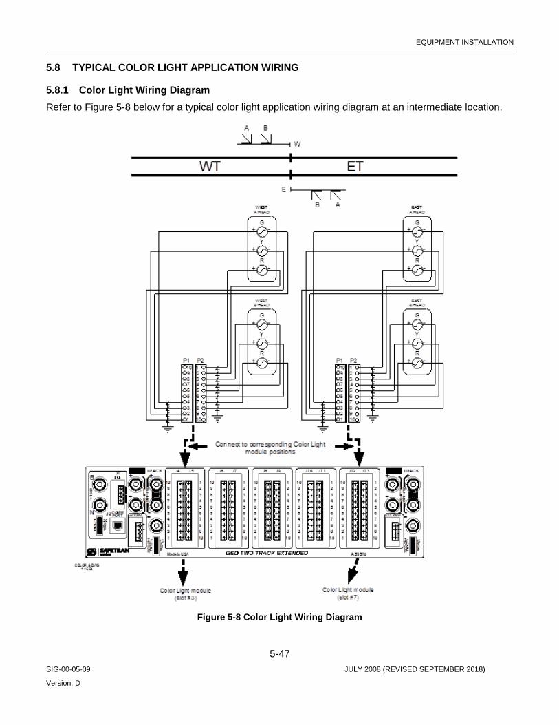
EQUIPMENT INSTALLATION
5-47 SIG-00-05-09 JULY 2008 (REVISED SEPTEMBER 2018)
Version: D
5.8 TYPICAL COLOR LIGHT APPLICATION WIRING
5.8.1 Color Light Wiring Diagram Refer to Figure 5-8 below for a typical color light application wiring diagram at an intermediate location.
Figure 5-8 Color Light Wiring Diagram
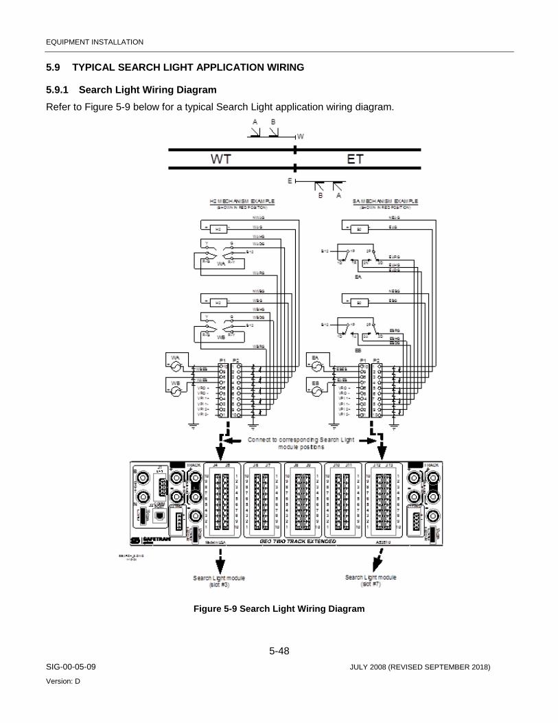
EQUIPMENT INSTALLATION
5-48 SIG-00-05-09 JULY 2008 (REVISED SEPTEMBER 2018)
Version: D
5.9 TYPICAL SEARCH LIGHT APPLICATION WIRING
5.9.1 Search Light Wiring Diagram Refer to Figure 5-9 below for a typical Search Light application wiring diagram.
Figure 5-9 Search Light Wiring Diagram
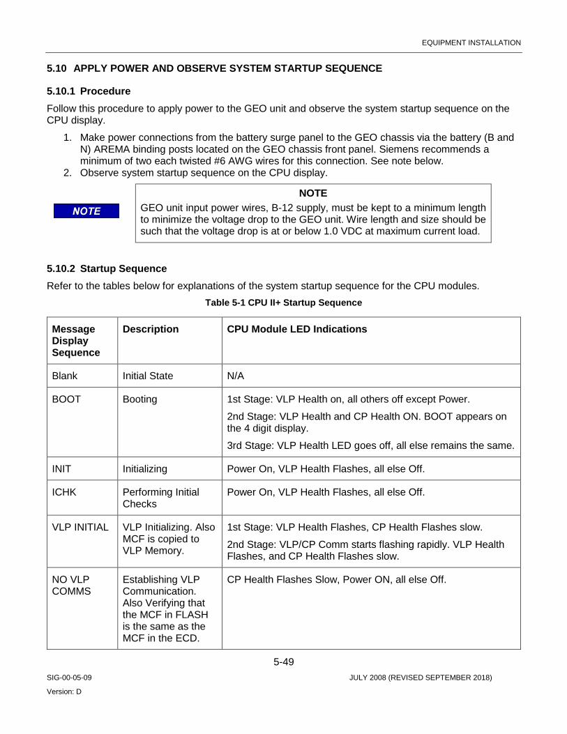
EQUIPMENT INSTALLATION
5-49 SIG-00-05-09 JULY 2008 (REVISED SEPTEMBER 2018)
Version: D
5.10 APPLY POWER AND OBSERVE SYSTEM STARTUP SEQUENCE
5.10.1 Procedure Follow this procedure to apply power to the GEO unit and observe the system startup sequence on the CPU display.
1. Make power connections from the battery surge panel to the GEO chassis via the battery (B and N) AREMA binding posts located on the GEO chassis front panel. Siemens recommends a minimum of two each twisted #6 AWG wires for this connection. See note below.
2. Observe system startup sequence on the CPU display.
NOTE GEO unit input power wires, B-12 supply, must be kept to a minimum length to minimize the voltage drop to the GEO unit. Wire length and size should be such that the voltage drop is at or below 1.0 VDC at maximum current load.
5.10.2 Startup Sequence Refer to the tables below for explanations of the system startup sequence for the CPU modules.
Table 5-1 CPU II+ Startup Sequence
Message Display Sequence
Description CPU Module LED Indications
Blank Initial State N/A
BOOT Booting 1st Stage: VLP Health on, all others off except Power.
2nd Stage: VLP Health and CP Health ON. BOOT appears on the 4 digit display.
3rd Stage: VLP Health LED goes off, all else remains the same.
INIT Initializing Power On, VLP Health Flashes, all else Off.
ICHK Performing Initial Checks
Power On, VLP Health Flashes, all else Off.
VLP INITIAL VLP Initializing. Also MCF is copied to VLP Memory.
1st Stage: VLP Health Flashes, CP Health Flashes slow.
2nd Stage: VLP/CP Comm starts flashing rapidly. VLP Health Flashes, and CP Health Flashes slow.
NO VLP COMMS
Establishing VLP Communication. Also Verifying that the MCF in FLASH is the same as the MCF in the ECD.
CP Health Flashes Slow, Power ON, all else Off.

EQUIPMENT INSTALLATION
5-50 SIG-00-05-09 JULY 2008 (REVISED SEPTEMBER 2018)
Version: D
Message Display Sequence
Description CPU Module LED Indications
* EFLA Preparing to download MCF from ECD.
CP Health OFF, VLP Health Flashes Fast, Power ON, all else OFF (VLP/CP COMM TX may be ON).
* 1-100% (Counts)
Downloading MCF from ECD.
VLP Health Flashes, Power ON, all else OFF (VLP/CP COMM TX may be ON).
* DONE Finished Downloading MCF.
VLP Health Flashes, Power ON, all else OFF
* BOOT Rebooting System CP Health ON, VLP Health Flashes fast, Power ON, all else off.
* INIT Initializing System CP Health OFF, VLP Health Flashes Fast, Power ON, all else off.
* ICHK Performing Initial Checks
CP Health OFF, VLP Health Flashes Fast, Power ON, all else off.
* VLP INITIAL
VLP Initializing 1st Stage: VLP Health Flashes, CP Health Flashes slow.
2nd Stage: VLP/CP Comm starts flashing rapidly, VLP Health Flashes and CP Health Flashes slow.
* NO VLP COMMS
Establishing VLP Communication. Also Verifying that the MCF in FLASH is the same as the MCF in the ECD.
CP Health Flashes Slow, Power ON, all else Off.
MCF SCROLLS
CP Health and VLP Health Flashing Slowly, VLP/CP COMM Flashing Rapidly, BACKPLANE COMM Flashing.
* These steps only occur when the MCF in FLASH is different from the MCF in the ECD.

EQUIPMENT INSTALLATION
5-51 SIG-00-05-09 JULY 2008 (REVISED SEPTEMBER 2018)
Version: D
Table 5-2 CPU III Startup Sequence
Message Display Sequence
Description CPU Module LED Indications
CPU3 Initial State Power On, VLP Health Flashes, CP Health Flashes
INIT Initializing 1st Stage: Power On, all LEDs flash but Backplane COMM
2nd Stage: Power On, VLP Health, CP Health, and Backplane COMM flash
FULLY OPERATIONAL
Performing Final Checks
Power On, VLP Health, CP Health, and Backplane COMM flash
MCF SCROLLS Operational Power On, VLP Health, CP Health, and Backplane COMM flash
5.10.3 MCF Format Following a successful startup sequence, the Module Configuration File (MCF) version name and number scroll across the CPU display from right to left.
5.10.4 Startup Errors If the startup sequence detects errors, other codes appear instead of the MCF. Refer to the Chapter 7, Setup and Configuration, for an explanation of error codes and corrective actions.
5.10.5 Turn off Track Blocks After power is applied to the GEO system, change the universal local control panel (ULCP) to LOCAL control. Notice that the track block indications energize, as can be seen on the ULCP. All the track block indicators will light solid red.
Turn off the track blocks by pressing the appropriate push buttons on the ULCP. Make sure that all the track block lights are off before proceeding.
5.10.6 Track Circuit Setup After the system is powered-up, follow the latest version of the GEO Coded Track Circuit Setup Procedure. A copy can be found in Section 7.7 of this manual. The track circuit setup can also be completed using a computer with DT software or Web Browser access (WebUI, CPU III only).
As described in the setup procedure, connect a meter to the METER terminals on the GEO unit.
5.10.7 Using the Meter Terminals To use the dedicated Meter terminals, refer to the Figure 5-10 and follow these steps:
1. With the unit powered-up, connect current meter leads across Meter terminal 1 and Meter terminal 2. The meter is shunted by the “current test link” and will indicate zero current.
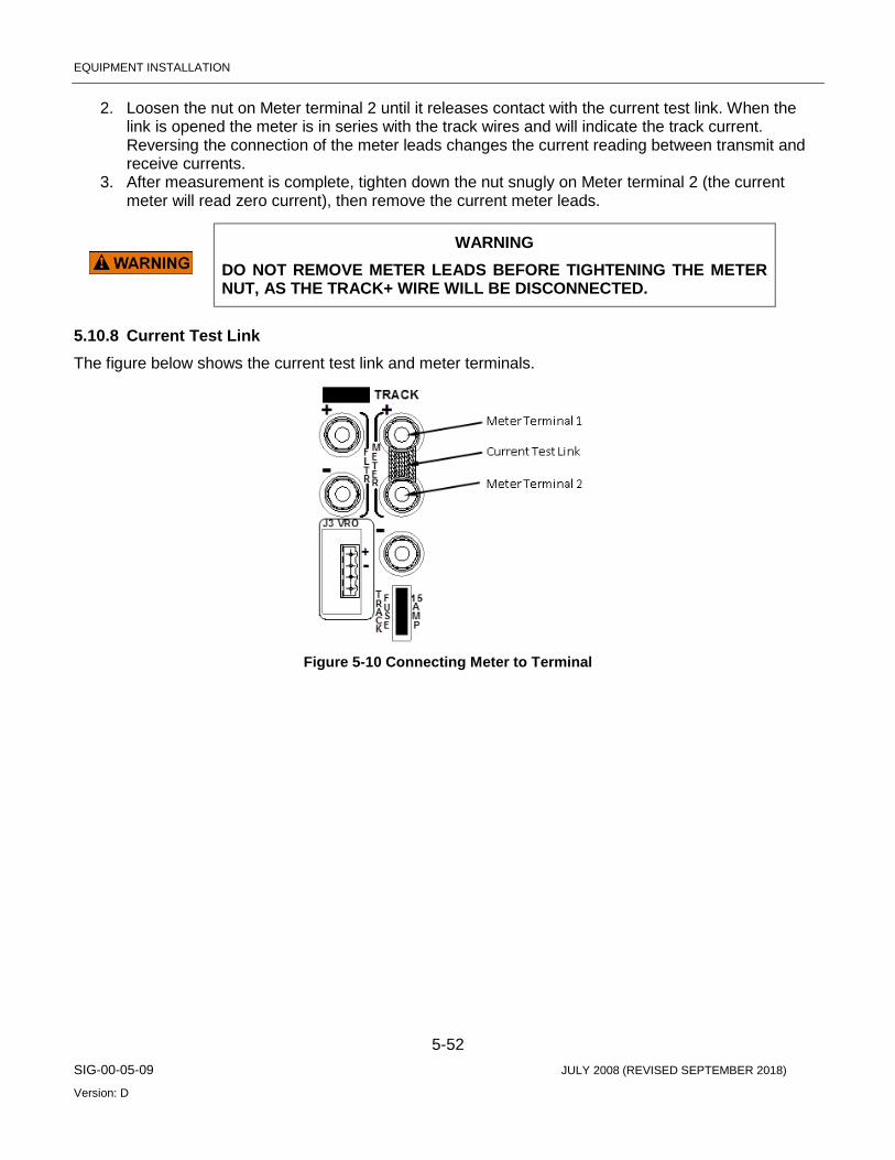
EQUIPMENT INSTALLATION
5-52 SIG-00-05-09 JULY 2008 (REVISED SEPTEMBER 2018)
Version: D
2. Loosen the nut on Meter terminal 2 until it releases contact with the current test link. When the link is opened the meter is in series with the track wires and will indicate the track current. Reversing the connection of the meter leads changes the current reading between transmit and receive currents.
3. After measurement is complete, tighten down the nut snugly on Meter terminal 2 (the current meter will read zero current), then remove the current meter leads.
WARNING
DO NOT REMOVE METER LEADS BEFORE TIGHTENING THE METER NUT, AS THE TRACK+ WIRE WILL BE DISCONNECTED.
5.10.8 Current Test Link The figure below shows the current test link and meter terminals.
Figure 5-10 Connecting Meter to Terminal

MAINTAINER INTERFACE
6-1 SIG-00-05-09 JULY 2008 (REVISED SEPTEMBER 2018)
Version: D
SECTION 6 MAINTAINER INTERFACE
6.0 PURPOSE A 4-character alphanumeric display unit and two push buttons are provided on the CPU module to perform basic maintenance and troubleshooting tasks when a laptop computer is unavailable. This chapter deals with various modes of operation and menu selections used to view status on GEO system configuration.
6.1 VIEWING SYSTEM SETTINGS Settings for track output voltage and current, and lamp output voltage can be viewed on the Maintainer Interface without disturbing system operation. However, other maintenance tasks could interfere with signal system operation.
WARNING
THE GEO SYSTEM IS PART OF THE RAILROAD SIGNAL SYSTEM. PERFORMING ANY MAINTENANCE OR ADJUSTMENT PROCEDURE ON THE GEO UNIT COULD AFFECT THE SIGNAL SYSTEM. THEREFORE, ALL SAFETY AND OPERATING RULES OF THE RAILROAD PERTAINING TO THE ADJUSTMENT OR MAINTENANCE OF THE SIGNAL SYSTEM MUST BE COMPLIED WITH.
6.1.1 Normal Operation During normal operation, the Module Configuration File (MCF) version number scrolls across the display unit from right to left. The MCF is loaded at the factory and tells the CPU which modules are installed in the unit.
On the CPU III, the MCF scrolls across the display, or, if the Navigate (NAV) button is selected, the IP address of the unit will scroll across the display.
If a failure is detected, error messages appear instead of the MCF version number. Refer to Chapter 7, System Setup and Configuration, of this manual for a complete explanation of error messages.
6.1.2 Viewing System Settings on the CPU II+ The CPU II+ front panel has two push buttons allow for viewing system settings. Pressing the Select (SEL) push button one time places the GEO unit in Menu mode. The module in slot 1 (CPU) is displayed. Pressing the Navigate (NAV) button moves down the menu to select slot 2 of the unit for configuration. Each successive press of the NAV button selects the next slot, from left to right, for configuration. To view parameters for a module slot, press the SEL push button. Parameters that can be viewed and changed vary with the type of module installed in the slot.
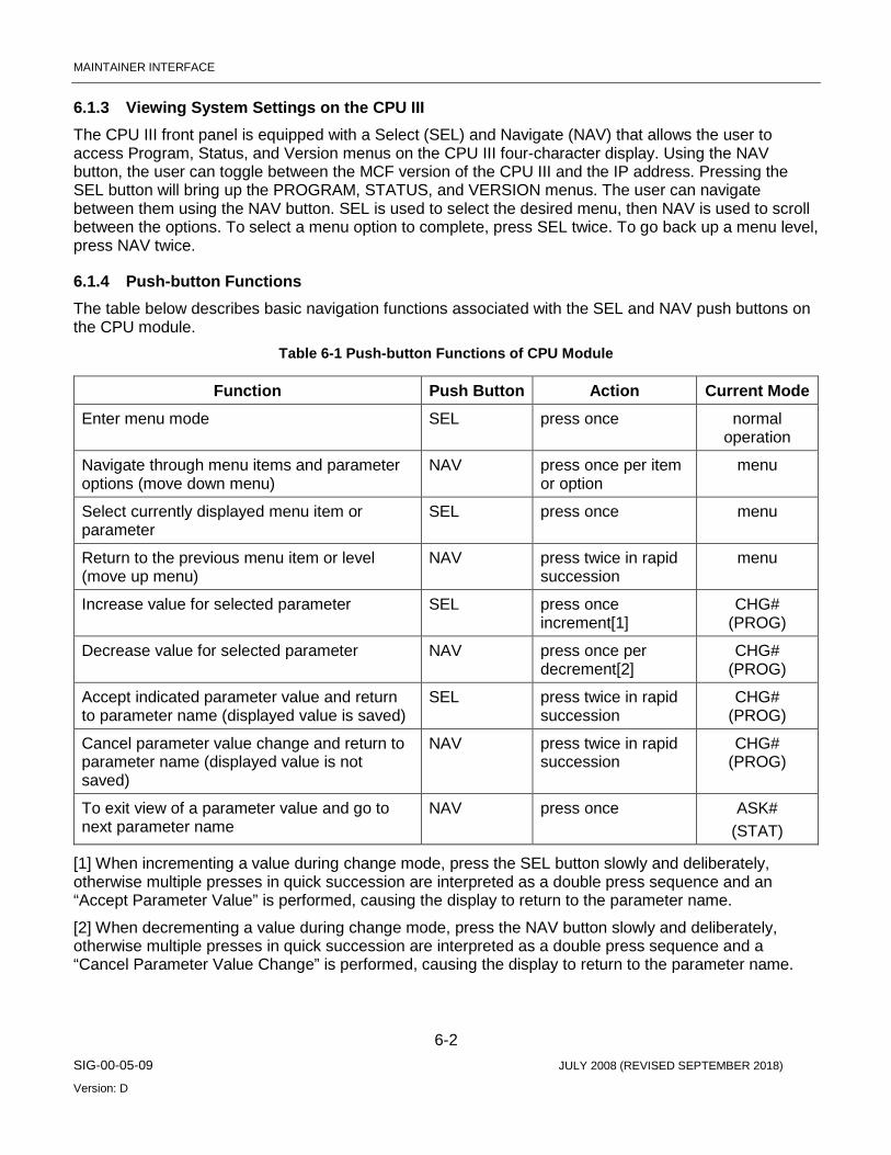
MAINTAINER INTERFACE
6-2 SIG-00-05-09 JULY 2008 (REVISED SEPTEMBER 2018)
Version: D
6.1.3 Viewing System Settings on the CPU III The CPU III front panel is equipped with a Select (SEL) and Navigate (NAV) that allows the user to access Program, Status, and Version menus on the CPU III four-character display. Using the NAV button, the user can toggle between the MCF version of the CPU III and the IP address. Pressing the SEL button will bring up the PROGRAM, STATUS, and VERSION menus. The user can navigate between them using the NAV button. SEL is used to select the desired menu, then NAV is used to scroll between the options. To select a menu option to complete, press SEL twice. To go back up a menu level, press NAV twice.
6.1.4 Push-button Functions The table below describes basic navigation functions associated with the SEL and NAV push buttons on the CPU module.
Table 6-1 Push-button Functions of CPU Module
Function Push Button Action Current Mode Enter menu mode SEL press once normal
operation
Navigate through menu items and parameter options (move down menu)
NAV press once per item or option
menu
Select currently displayed menu item or parameter
SEL press once menu
Return to the previous menu item or level (move up menu)
NAV press twice in rapid succession
menu
Increase value for selected parameter SEL press once increment[1]
CHG# (PROG)
Decrease value for selected parameter NAV press once per decrement[2]
CHG# (PROG)
Accept indicated parameter value and return to parameter name (displayed value is saved)
SEL press twice in rapid succession
CHG# (PROG)
Cancel parameter value change and return to parameter name (displayed value is not saved)
NAV press twice in rapid succession
CHG# (PROG)
To exit view of a parameter value and go to next parameter name
NAV press once ASK# (STAT)
[1] When incrementing a value during change mode, press the SEL button slowly and deliberately, otherwise multiple presses in quick succession are interpreted as a double press sequence and an “Accept Parameter Value” is performed, causing the display to return to the parameter name.
[2] When decrementing a value during change mode, press the NAV button slowly and deliberately, otherwise multiple presses in quick succession are interpreted as a double press sequence and a “Cancel Parameter Value Change” is performed, causing the display to return to the parameter name.
MAINTAINER INTERFACE
6-3 SIG-00-05-09 JULY 2008 (REVISED SEPTEMBER 2018)
Version: D
6.1.5 Menu Mode Timeout If no CPU module push-button activity occurs for a period of 6 minutes, the CPU exits the menu mode and returns to normal operation with the MCF version scrolling on the display.
6.1.6 Exiting Menu Mode To exit Menu mode and return to normal operation, press the NAV push button twice in rapid succession repeatedly until the MCF version number scrolls across the display.
6.1.7 For Further Information Contact Siemens Technical Support at: 1-800-793-7233 if more information is desired on the operation of the Maintainer Push Button Interface.

MAINTAINER INTERFACE
6-4 SIG-00-05-09 JULY 2008 (REVISED SEPTEMBER 2018)
Version: D
This Page Intentionally Left Blank
SYSTEM SETUP AND CONFIGURATION
7-1 SIG-00-05-09 JULY 2008 (REVISED SEPTEMBER 2018)
Version: D
SECTION 7 SYSTEM SETUP AND CONFIGURATION
7.0 SETUP AND CONFIGURATION PROCESS To setup and configure a GEO unit, complete the following procedures:
1. Apply power to the GEO unit or reboot the system if power is already applied. a. To reboot a GEO unit and perform a new system initialization, perform one of the following
procedures: i. Remove, then reapply power. ii. Unseat, then reseat the CPU module.
2. Observe the system initialization sequence on the CPU display. a. See System Initialization, 7.1, for initialization sequence indications.
3. If site-specific Module Configuration File (MCF) or Module Executable Files (MEF) must be loaded, go to Step 4. If not, go to Step 5.
4. If site-specific MCF or MEF files must be loaded for the location, a laptop computer using WebUI or the Diagnostic Terminal is used to load software. For use of the DT refer to SIG-00-04-17, for use of the WebUI refer to How to Load a New MCF 7.3 for procedure).
a. Load site-specific Module Configuration File (MCF) or Module Executable Files (MEF), as necessary. Reboot the system and observe the system initialization sequence.
5. Correct any configuration errors. a. Check site plans for correct module locations. b. See Configuration Errors 7.2, for an explanation of configuration errors and corrective
actions for each. 6. Set system time and date.
a. See How to Set System Time Section 7.4 and Date Section 7.5. 7. Adjust Track module output voltage and current limit.
a. See How to Set Track Module Voltage and Current Limit, 7.6 and/or adjust Line module Transmit Voltage - See How to Set Line Transmit Voltage, 7.8.
8. Adjust Track module input current. a. See How to Set Track Module Receive Current, 7.7 and/or adjust Line module Receive
Threshold - See How to Set Line Module Receive Threshold, Error! Reference source not found..
9. Adjust lamp voltage for signal heads. a. See How to Set Lamp Voltage for Color Light Signal Heads, 7.9.
10. Adjust Search Light signal mechanism parameters. a. See How to Set Search Light Signal Mechanism Parameters, 7.10.
11. Verify all other I/O module configuration options and adjust as necessary. a. Refer to site plans at the location and verify/adjust all other I/O module configuration
option settings. b. Menu maps detailing I/O module configuration option change procedures are located in
Chapter 6, Maintainer Interface, of this manual. 12. Perform a complete operational check of the system.
a. Refer to Troubleshooting (SECTION 9) of this manual for operational check procedures. 13. Perform all required FRA tests and complete and file all required forms.
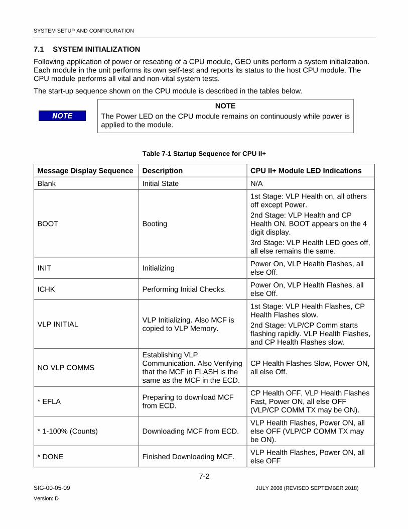
SYSTEM SETUP AND CONFIGURATION
7-2 SIG-00-05-09 JULY 2008 (REVISED SEPTEMBER 2018)
Version: D
7.1 SYSTEM INITIALIZATION Following application of power or reseating of a CPU module, GEO units perform a system initialization. Each module in the unit performs its own self-test and reports its status to the host CPU module. The CPU module performs all vital and non-vital system tests.
The start-up sequence shown on the CPU module is described in the tables below.
NOTE The Power LED on the CPU module remains on continuously while power is applied to the module.
Table 7-1 Startup Sequence for CPU II+
Message Display Sequence Description CPU II+ Module LED Indications Blank Initial State N/A
BOOT Booting
1st Stage: VLP Health on, all others off except Power. 2nd Stage: VLP Health and CP Health ON. BOOT appears on the 4 digit display. 3rd Stage: VLP Health LED goes off, all else remains the same.
INIT Initializing Power On, VLP Health Flashes, all else Off.
ICHK Performing Initial Checks. Power On, VLP Health Flashes, all else Off.
VLP INITIAL VLP Initializing. Also MCF is copied to VLP Memory.
1st Stage: VLP Health Flashes, CP Health Flashes slow. 2nd Stage: VLP/CP Comm starts flashing rapidly. VLP Health Flashes, and CP Health Flashes slow.
NO VLP COMMS
Establishing VLP Communication. Also Verifying that the MCF in FLASH is the same as the MCF in the ECD.
CP Health Flashes Slow, Power ON, all else Off.
* EFLA Preparing to download MCF from ECD.
CP Health OFF, VLP Health Flashes Fast, Power ON, all else OFF (VLP/CP COMM TX may be ON).
* 1-100% (Counts) Downloading MCF from ECD. VLP Health Flashes, Power ON, all else OFF (VLP/CP COMM TX may be ON).
* DONE Finished Downloading MCF. VLP Health Flashes, Power ON, all else OFF
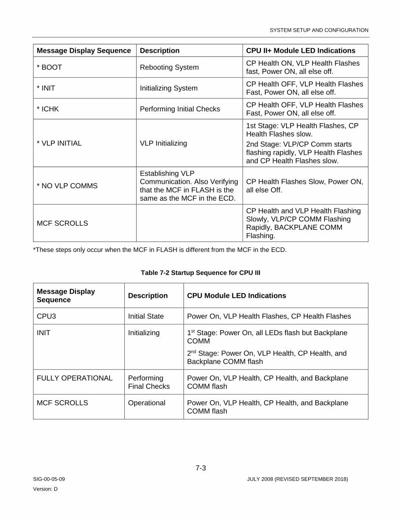
SYSTEM SETUP AND CONFIGURATION
7-3 SIG-00-05-09 JULY 2008 (REVISED SEPTEMBER 2018)
Version: D
Message Display Sequence Description CPU II+ Module LED Indications
* BOOT Rebooting System CP Health ON, VLP Health Flashes fast, Power ON, all else off.
* INIT Initializing System CP Health OFF, VLP Health Flashes Fast, Power ON, all else off.
* ICHK Performing Initial Checks CP Health OFF, VLP Health Flashes Fast, Power ON, all else off.
* VLP INITIAL VLP Initializing
1st Stage: VLP Health Flashes, CP Health Flashes slow. 2nd Stage: VLP/CP Comm starts flashing rapidly, VLP Health Flashes and CP Health Flashes slow.
* NO VLP COMMS
Establishing VLP Communication. Also Verifying that the MCF in FLASH is the same as the MCF in the ECD.
CP Health Flashes Slow, Power ON, all else Off.
MCF SCROLLS
CP Health and VLP Health Flashing Slowly, VLP/CP COMM Flashing Rapidly, BACKPLANE COMM Flashing.
*These steps only occur when the MCF in FLASH is different from the MCF in the ECD.
Table 7-2 Startup Sequence for CPU III
Message Display Sequence Description CPU Module LED Indications
CPU3 Initial State Power On, VLP Health Flashes, CP Health Flashes
INIT Initializing 1st Stage: Power On, all LEDs flash but Backplane COMM
2nd Stage: Power On, VLP Health, CP Health, and Backplane COMM flash
FULLY OPERATIONAL Performing Final Checks
Power On, VLP Health, CP Health, and Backplane COMM flash
MCF SCROLLS Operational Power On, VLP Health, CP Health, and Backplane COMM flash

SYSTEM SETUP AND CONFIGURATION
7-4 SIG-00-05-09 JULY 2008 (REVISED SEPTEMBER 2018)
Version: D
7.1.1 Status Indications The unit Module Configuration File (MCF) version number scrolls from right to left on the CPU display following a successful system initialization. If errors are detected during system initialization, error messages appear instead of, or in addition to, the scrolling MCF. Refer to the next section in this chapter for configuration error messages.
7.2 CONFIGURATION ERRORS
7.2.1 Error Indications Some GEO configuration options are defined in the MCF, but others must be assigned or verified during setup. Failure to do so correctly can generate error indications.
Site plans for a location define configuration options and states.
7.2.2 Fatal Versus Non-Fatal Configuration Errors If non-fatal configuration errors are detected during system startup, the system becomes operational, but an error message appears on the CPU module display.
If fatal configuration errors are detected during system startup, the system remains inoperative, and a fatal error message appears on the CPU module display. Vital configuration options must be assigned or verified, and the system must be rebooted to become operational. Fatal error messages often relate to Chassis ID Chip (CIC) data elements. See the table below. Fatal and non-fatal error message types are presented on pages 7-8 and 7-9.
7.2.3 Bad CIC Data Errors The following table summarizes the data stored in the CIC. If this data is incorrect, a fatal error results.
Table 7-3 Fatal CIC Error Messages
CIC Data Description MCF CRC Module Configuration File Cyclic Redundancy Check – a configuration validation
number calculated from the contents of an approved MCF. This number is used to verify proper configuration of the unit.
SIN Site Identification Number – an assigned ATCS address for the location.
UCN Unique Check Number – a configuration validation number calculated from the contents of an approved MCF, SIN, and the vital user options and timer settings stored in the CIC.
Configuration options
Field-configured vital user and timer options for the location, including application logic and I/O voltage/current settings.
7.2.4 Fatal Error Codes The following table describes fatal error codes and corrective action for each error code. When an error is detected, the displays reads “ERR:”, followed by the applicable error code.

SYSTEM SETUP AND CONFIGURATION
7-5 SIG-00-05-09 JULY 2008 (REVISED SEPTEMBER 2018)
Version: D
Table 7-4 Fatal Error Codes
Error Codes Problem Indicated Corrective Action UCN* Configuration error - UCN incorrect Correct UCN and reboot.
CRC* Configuration error - MCF CRC incorrect Correct MCF CRC and reboot.
SIN* Configuration error – SIN incorrect Correct SIN and reboot.
MCF* Configuration error – MCF corrupted or invalid Reload MCF and reboot.
MCI* Configuration error – hardware and MEF configuration indexes do not match Correct configuration and reboot.
ADR* Invalid ATCS address Correct the ATCS address by selecting the SIN, and reboot.
NOTE Attempting to boot up a GEO unit with an ECD holding an invalid MCF for that GEO unit can result in multiple error codes including: UCN*, CRC*, and MCF*.
7.2.5 Confirm Configuration Settings Refer to site plans at the location and confirm correct CPU module vital and non-vital configuration settings. Adjust as necessary.
Menu maps detailing CPU module configuration option change procedures are located in the Chapter 6, Maintainer Interface.
7.3 HOW TO LOAD A NEW MCF VIA WEBUI
7.3.1 Accessing Siemens WebUI The CPU III module provides a Web Interface which enables the user to configure the GEO locally as well as remotely through the Laptop/Ethernet port on the front of the CPU III module. The Laptop Port default protocol is set as DHCP Server. The CPU III will display an IP address scrolling across the four-character display. This can be accessed by using the Navigate (NAV) button to move between the scrolling displayed text. The WebUI uses the HTTP Secure (https) protocol. The CPU III DHCP Server protocol will assign the laptop an IP address and connect the user to the GEO. The WebUI supports the following web browsers:
• IE 10 and 11 • Firefox (version 46.x) • Chrome (version 55.x)

SYSTEM SETUP AND CONFIGURATION
7-6 SIG-00-05-09 JULY 2008 (REVISED SEPTEMBER 2018)
Version: D
Open a web browser and type in https:// followed by the IP address of the CPU III. The browser may give the following screens regarding the connection.
Figure 7-1 Unsecure Connection Warning
Click the Advanced option and select the option to proceed to the WebUI.
The WebUI will then appear. Select the user name as Admin (default). There is no Maintainer login option for GEO WebUI.

SYSTEM SETUP AND CONFIGURATION
7-7 SIG-00-05-09 JULY 2008 (REVISED SEPTEMBER 2018)
Version: D
The default password is Siemens (case sensitive) to open the session. If a specific Admin password has been set, enter this.
Figure 7-2 WebUI Login Screen
NOTE The WebUI has a 1-minute session timeout. If the web browser is closed without selecting Logout. The user will not be able to log back in for 1 minute.
The WebUI has buttons at the top which allow the user to select the various functions.
Figure 7-3 WebUI Tool Bar
From the Tool Bar select the Maintenance icon. Select VLP then MCF from the menu on the left side of the display. This will show the MCF upload screen.
Figure 7-4 MCF Upload Screen
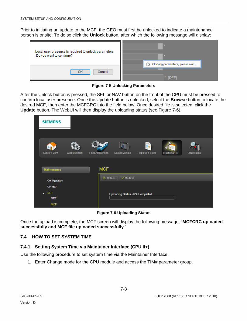
SYSTEM SETUP AND CONFIGURATION
7-8 SIG-00-05-09 JULY 2008 (REVISED SEPTEMBER 2018)
Version: D
Prior to initiating an update to the MCF, the GEO must first be unlocked to indicate a maintenance person is onsite. To do so click the Unlock button, after which the following message will display:
Figure 7-5 Unlocking Parameters
After the Unlock button is pressed, the SEL or NAV button on the front of the CPU must be pressed to confirm local user presence. Once the Update button is unlocked, select the Browse button to locate the desired MCF, then enter the MCFCRC into the field below. Once desired file is selected, click the Update button. The WebUI will then display the uploading status (see Figure 7-6).
Figure 7-6 Uploading Status
Once the upload is complete, the MCF screen will display the following message, “MCFCRC uploaded successfully and MCF file uploaded successfully.”
7.4 HOW TO SET SYSTEM TIME
7.4.1 Setting System Time via Maintainer Interface (CPU II+) Use the following procedure to set system time via the Maintainer Interface.
1. Enter Change mode for the CPU module and access the TIM# parameter group.
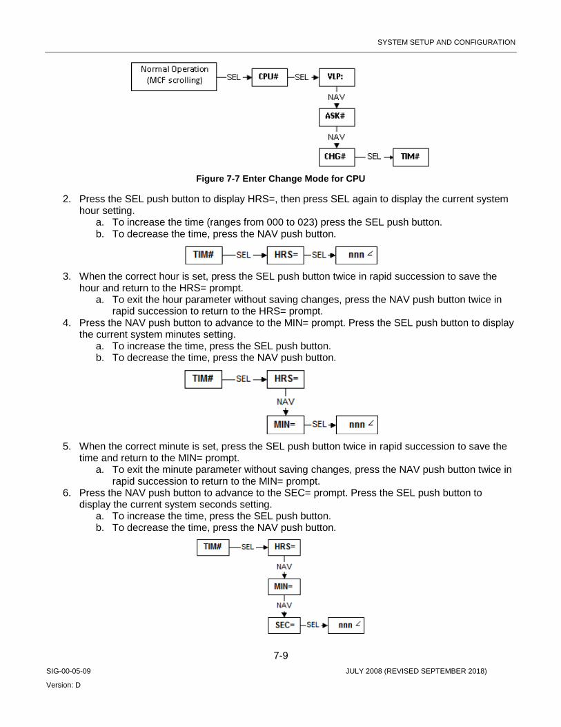
SYSTEM SETUP AND CONFIGURATION
7-9 SIG-00-05-09 JULY 2008 (REVISED SEPTEMBER 2018)
Version: D
Figure 7-7 Enter Change Mode for CPU
2. Press the SEL push button to display HRS=, then press SEL again to display the current system hour setting.
a. To increase the time (ranges from 000 to 023) press the SEL push button. b. To decrease the time, press the NAV push button.
3. When the correct hour is set, press the SEL push button twice in rapid succession to save the
hour and return to the HRS= prompt. a. To exit the hour parameter without saving changes, press the NAV push button twice in
rapid succession to return to the HRS= prompt. 4. Press the NAV push button to advance to the MIN= prompt. Press the SEL push button to display
the current system minutes setting. a. To increase the time, press the SEL push button. b. To decrease the time, press the NAV push button.
5. When the correct minute is set, press the SEL push button twice in rapid succession to save the
time and return to the MIN= prompt. a. To exit the minute parameter without saving changes, press the NAV push button twice in
rapid succession to return to the MIN= prompt. 6. Press the NAV push button to advance to the SEC= prompt. Press the SEL push button to
display the current system seconds setting. a. To increase the time, press the SEL push button. b. To decrease the time, press the NAV push button.

SYSTEM SETUP AND CONFIGURATION
7-10 SIG-00-05-09 JULY 2008 (REVISED SEPTEMBER 2018)
Version: D
7. When the correct second is set, press the SEL push button twice in rapid succession to save the time and return to the SEC= prompt.
a. To exit the second parameter without saving changes, press the NAV push button twice in rapid succession to return to the SEC= prompt.
8. Press the NAV push button to return to the HRS= prompt, then press NAV twice in rapid succession to return to the TIM# parameter group.
7.4.2 Setting System Time and Date via WebUI (CPU III) To set the time and date via the WebUI, select the Configuration menu, then from the left side menu choose Vital Configuration > Site Configuration > Time. The Time screen allows you to set the Time Zone, Date, and Clock time.
Figure 7-8 Setting System Time and Date

SYSTEM SETUP AND CONFIGURATION
7-11 SIG-00-05-09 JULY 2008 (REVISED SEPTEMBER 2018)
Version: D
7.5 HOW TO SET SYSTEM DATE (CPU II+) Use the following procedure to set system date, or the WebUI may be used if available (see Section 7.4.2.)
1. From the TIM# parameter group, press the NAV push button to access the DAT# parameter group.
2. Press the SEL push button to display YRS=, then press SEL again to display the current system
year setting. a. To increase the year, press the SEL push button. b. To decrease the year, press the NAV push button.
3. When the correct year is set, press the SEL push button twice in rapid succession to save the
year and return to the YRS= prompt. a. To exit the year parameter without saving changes, press the NAV push button twice in
rapid succession to return to the YRS= prompt. 4. Press the NAV push button to advance to the MON= prompt. Then press the SEL push button to
display the current system month setting.
a. To increase the month, press the SEL push button. b. To decrease the month, press the NAV push button.
5. When the correct month is set, press the SEL push button twice in rapid succession to save the month and return to the MON= prompt.
a. To exit the month parameter without saving changes, press the NAV push button twice in rapid succession to return to the MON= prompt.
6. Press the NAV push button to advance to the DAY= prompt. Press the SEL push button to display the current system day setting.
a. To increase the day, press the SEL push button. b. To decrease the day, press the NAV push button.

SYSTEM SETUP AND CONFIGURATION
7-12 SIG-00-05-09 JULY 2008 (REVISED SEPTEMBER 2018)
Version: D
7. When the correct day is set, press the SEL push button twice in rapid succession to save the day and return to the DAY= prompt.
a. To exit the day parameter without saving changes, press the NAV push button twice in rapid succession to return to the DAY= prompt.
8. To exit the time and date parameter groups and return to normal operation, press the NAV push button twice in rapid succession repeatedly, until the MCF version number is scrolling on the CPU display.
7.6 HOW TO SET TRACK MODULE VOLTAGE AND CURRENT LIMITS
7.6.1 Track Circuit Setup Follow the latest version of the GEO Coded Track Circuit Setup Procedure. A copy is located at the end of this chapter.
7.6.2 Track Voltage Table Set Track output voltage according the track type, track length and ballast conditions shown in the table below.
Table 7-5 Track Voltage Table
Length Feet (Meters)
VOLTS, RAIL-TO-RAIL 3 Ohms Ballast
140 Lbs/Yd – 69.4 kg/m 5 Ohms Ballast
140 Lbs/Yd – 69.4 kg/m Continuous Welded Rail Bonded Joints Continuous
Welded Rail Bonded Joints
5,000 (1,524) 1.1 1.3 1.1 1.2
6,000 (1,829) 1.2 1.3 1.1 1.3
7,000 (2,134) 1.2 1.4 1.2 1.3
8,000 (2,438) 1.3 1.5 1.2 1.4
9,000 (2,743) 1.3 1.7 1.2 1.5
10,000 (3,048) 1.4 1.8 1.3 1.6
11,000 (3,353) 1.5 1.9 1.3 1.7
12,000 (3,658) 1.5 2.1 1.4 1.8
13,000 (3,962) 1.6 2.3 1.4 1.9
14,000 (4,267) 1.7 2.5 1.5 2.0
15,000 (4,572) 1.8 2.7 1.5 2.1
16,000 (4,877) 1.9 3.0 1.6 2.3
17,000 (5,182) 2.0 3.3 1.7 2.4
18,000 (5,486) 2.1 3.6 1.8 2.6
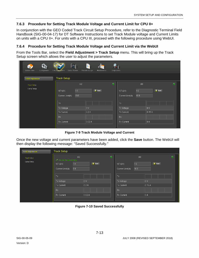
SYSTEM SETUP AND CONFIGURATION
7-13 SIG-00-05-09 JULY 2008 (REVISED SEPTEMBER 2018)
Version: D
7.6.3 Procedure for Setting Track Module Voltage and Current Limit for CPU II+ In conjunction with the GEO Coded Track Circuit Setup Procedure, refer to the Diagnostic Terminal Field Handbook (SIG-00-04-17) for DT Software Instructions to set Track Module voltage and Current Limits on units with a CPU II+. For units with a CPU III, proceed with the following procedure using WebUI.
7.6.4 Procedure for Setting Track Module Voltage and Current Limit via the WebUI From the Tools Bar, select the Field Adjustment > Track Setup menu. This will bring up the Track Setup screen which allows the user to adjust the parameters.
Figure 7-9 Track Module Voltage and Current
Once the new voltage and current parameters have been added, click the Save button. The WebUI will then display the following message: “Saved Successfully.”
Figure 7-10 Saved Successfully

SYSTEM SETUP AND CONFIGURATION
7-14 SIG-00-05-09 JULY 2008 (REVISED SEPTEMBER 2018)
Version: D
7.7 HOW TO SET A TRACK MODULE RECEIVE CURRENT 7.7.1 Importance of Receive Current In order for the Track module to function properly, the receive current must be set to the proper value for a particular quality of ballast. The GEO track circuit is properly adjusted when receive current is:
• 1150 - 1350 mA with very dry or frozen ballast. • 850 – 1150 mA with normal ballast. • 650 - 850 mA for very wet ballast.
7.7.2 Jumper Settings Each GEO Track module can be set for the optimal track circuit receive (RX) current using a jumper to select different resistance values.
One of five different resistance values can be selected. On all PCBs, J2 selects the maximum resistance (.88 ohms), and J6 selects zero ohms resistance. Siemens recommends the receive jumper be set for .30 ohms (J4) initially. This allows the signal maintainer to make minor adjustments to the track circuit without going to the transmit end of the track circuit.
7.7.3 Test Equipment Required A peak-reading meter is required to set track circuit receive current when setting without the DT. Refer to the latest version of the GEO Coded Track Circuit Setup Procedure. A copy is located at the end of this chapter.
7.7.4 Procedure In conjunction with the GEO Coded Track Circuit Setup Procedure, use the following procedure if it becomes necessary to adjust track circuit receive current, or the DT may be used if available. When using the DT refer to manual SIG-00-04-17.
Use the track circuit checklist to record the track circuit values. See the checklist on next page.
NOTE These steps are general guidelines and may vary, depending on actual track conditions.
1. Set voltage and current limit at the transmit end of the track circuit in accordance with Track Voltage Tables in the previous section of this chapter.
2. At the receive end of the track circuit, connect a peak-reading ammeter in series with the track circuit to measure the receive current.
3. On the Track module, connect the RX current jumper to position J4 and measure received current.
4. Receive current should fall within one of the following ranges: • 1150 - 1350 mA with very dry or frozen ballast. • 850 – 1150 mA with normal ballast. • 650 - 850 mA for very wet ballast. 5. If the receive current requires adjustment, move the RX jumper, then measure the current again.
Repeat until the current is within range for the ballast conditions. • To decrease the current reading, move the jumper to J2 or J3. • To increase the current reading, move the jumper to J5, or J6.
SYSTEM SETUP AND CONFIGURATION
7-15 SIG-00-05-09 JULY 2008 (REVISED SEPTEMBER 2018)
Version: D
7.7.5 About This Checklist A checklist helps to keep a record of the dates that track circuit setups are performed.
A well-kept checklist can be valuable when troubleshooting, and when replacing modules. The list can provide values of previous track current readings. A checklist should be kept for every signal location.
7.7.6 Checklist Form A form is located at the end of this chapter and can be copied for use. The form is shown below in reduced size.
Table 7-6 GEO Track Circuit Setup Checklist
GEO Track Circuit Setup Checklist Signal Location No. __________________________
Reason for Call Track Conditions Battery Voltage
Track Circuit Measurements Meter Type
Date Initials
Routine Maintenance
Trouble Call
Dry Damp Wet VCO TX Current
RX Current
Jumper Setting
7.7.7 Instructions for Completing the Checklist Follow the instructions below when filling out the checklist form.

SYSTEM SETUP AND CONFIGURATION
7-16 SIG-00-05-09 JULY 2008 (REVISED SEPTEMBER 2018)
Version: D
Table 7-7 Track Circuit Checklist Instructions
Area on form What to write
Signal location No.
The location number as shown on the site plan.
Reason for call Check routine maintenance if you are doing normal scheduled maintenance. Check trouble call if you were called out to fix a problem.
Track condition Check dry, damp, or wet, based on the condition of the track and ballast.
Battery voltage Measure battery voltage and write reading in the column. This voltage should be measured at the battery input terminals (B, N).
Track circuit measurements
Use this area to record the voltage and current as you measure the track circuit. Write transmitting voltage in the VCO column. Write the transmit and receive current in the TX and RX current columns. Write the position of the jumper setting on the Track module (such as J4) in the jumper setting column.
Meter type Write in the type of meter you used to measure the track circuit, such as the Triplett 2000.
Date Date of the maintenance or service call.
Initials Initials of technician completing the checklist.
7.8 HOW TO SET LINE MODULE TRANSMIT VOLTAGE AND RECEIVE THRESHOLD
7.8.1 How to Set Line Module Transmit Voltage Using DT Refer to the Diagnostic Terminal Field Handbook (SIG-00-04-17) for DT Software Instructions to set Line Module Transmit Voltage and Receive Threshold on units with a CPU II+. For units with a CPU III, proceed with the following procedure using WebUI.
NOTE VRX must be set at least 1 volt less than VTX (VTX should be set first, as detailed in the previous procedure). Any attempt to set VRX higher than VTX will result in the default value being set (VTX minus 1 volt).
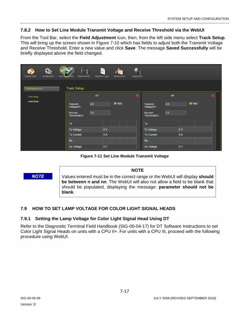
SYSTEM SETUP AND CONFIGURATION
7-17 SIG-00-05-09 JULY 2008 (REVISED SEPTEMBER 2018)
Version: D
7.8.2 How to Set Line Module Transmit Voltage and Receive Threshold via the WebUI From the Tool Bar, select the Field Adjustment icon, then, from the left side menu select Track Setup. This will bring up the screen shown in Figure 7-10 which has fields to adjust both the Transmit Voltage and Receive Threshold. Enter a new value and click Save. The message Saved Successfully will be briefly displayed above the field changed.
Figure 7-11 Set Line Module Transmit Voltage
NOTE Values entered must be in the correct range or the WebUI will display should be between n and nn. The WebUI will also not allow a field to be blank that should be populated, displaying the message: parameter should not be blank.
7.9 HOW TO SET LAMP VOLTAGE FOR COLOR LIGHT SIGNAL HEADS
7.9.1 Setting the Lamp Voltage for Color Light Signal Head Using DT Refer to the Diagnostic Terminal Field Handbook (SIG-00-04-17) for DT Software Instructions to set Color Light Signal Heads on units with a CPU II+. For units with a CPU III, proceed with the following procedure using WebUI.

SYSTEM SETUP AND CONFIGURATION
7-18 SIG-00-05-09 JULY 2008 (REVISED SEPTEMBER 2018)
Version: D
NOTE It is recommended that the lamp output voltage setting on each color light module be adjusted to meet the railroad required voltage at the farthest signal lamp and/or LED unit (Minimize the voltage drop over the lighting circuit variable resister). Utilize the variable lighting circuit resister in the signal housing and/or bungalow to adjust all other signal lamps assigned to the same color light module to meet the required lamp voltage. Minimizing the voltage drop over variable signal lighting resistors can reduce the input ampere demand to the GEO unit, especially during a prolonged power outage when the color light DC-DC converter is attempting to continually meet the targeted output voltage. This will reduce GEO ampere demand and prolong battery life.
7.9.2 Setting the Lamp Voltage for Color Light Signal Head via the WebUI From the Tool Bar, select the Field Adjustment icon, then, from the left side menu select Lamp Setup. This will bring up the screen shown in Figure 7-11 which has fields to adjust the Lamp Voltage. Enter a new value and click Save. The message Saved Successfully will be briefly displayed above the field changed.
Figure 7-12 Adjust Lamp Voltage
7.10 HOW TO SET SEARCH LIGHT MECHANISM PARAMETERS
7.10.1 Search Light Parameters Three parameters can be adjusted for Search Light signal heads.
• Debounce time • Lamp voltage • Mechanism position correspondence time for each signal head

SYSTEM SETUP AND CONFIGURATION
7-19 SIG-00-05-09 JULY 2008 (REVISED SEPTEMBER 2018)
Version: D
7.10.2 Procedure for Setting Search Light Parameters Using DT Refer to the Diagnostic Terminal Field Handbook (SIG-00-04-17) for DT Software Instructions to set Color Light Signal Heads on units with a CPU II+. For units with a CPU III, proceed with the following procedure using WebUI.
NOTE It is recommended that the lamp output voltage setting on each color light module be adjusted to meet the railroad required voltage at the farthest signal lamp and/or LED unit (Minimize the voltage drop over the lighting circuit variable resister). Utilize the variable lighting circuit resister in the signal housing and/or bungalow to adjust all other signal lamps assigned to the same color light module to meet the required lamp voltage. Minimizing the voltage drop over variable signal lighting resistors can reduce the input ampere demand to the GEO unit, especially during a prolonged power outage when the color light DC-DC converter is attempting to continually meet the targeted output voltage. This will reduce GEO ampere demand and prolong battery life.
7.10.3 Procedure for Setting Search Light Parameters with the WebUI
7.10.3.1 Set Lamp Voltage and Mechanism Position Correspondence Time From the Tool Bar, select the Field Adjustment icon, then, from the left side menu select Lamp Setup. This will bring up the screen shown in Figure 7-12 which has fields to adjust the Lamp Voltage and Mechanism Position Correspondence Time for both signal heads. Enter a new value and click Save. The message Saved Successfully will be briefly displayed above the field changed.
Figure 7-13 Setting Search Light Parameters

SYSTEM SETUP AND CONFIGURATION
7-20 SIG-00-05-09 JULY 2008 (REVISED SEPTEMBER 2018)
Version: D
7.10.3.2 Set Debounce Time To access the VPI Debounce parameters, select Configuration from the Tool Bar. From the left side of the screen select Vital Configuration > PHYSICAL configuration > MODULE configuration then the correct slot number for the Search Light Module. To unlock the parameters for editing, the Unlock button must be selected and then either the SEL or NAV button on the front of the CPU to confirm user presence.
Figure 7-14 Unlock Parameters
Once the parameters are unlocked, a new value can be entered into the Debounce field, then click Save. The screen will then briefly display the following message: Saved Parameters Successfully.
Figure 7-15 Search Light Debounce Parameter
MAINTENANCE
8-1 SIG-00-05-09 JULY 2008 (REVISED SEPTEMBER 2018)
Version: D
SECTION 8 MAINTENANCE
8.0 TASKS Digital control systems like GEO require very little maintenance. In general, maintenance tasks are confined to periodic inspections as required by the railroad and FRA.
These include the following tests/checks, at a minimum:
• Battery voltage • Track receive current • Signal lamp voltage
Maintenance and troubleshooting activities may lead to module and/or module MEF replacement. Such modifications will require a minimum set of test procedures to be executed – these are documented in the following sections. In addition to these minimum test procedures, please refer to official release notes for test procedures specific to the module hardware and software being used.
8.1 VIEWING SYSTEM SETTINGS Settings for track output voltage and the output current limit, along with the lamp output voltage can be viewed on the Maintainer Interface without disturbing system operation. However, other maintenance tasks can interfere with signal system operation.
WARNING THE GEO SYSTEM IS PART OF THE RAILROAD SIGNAL SYSTEM. PERFORMING ANY MAINTENANCE OR ADJUSTMENT PROCEDURE ON THE GEO UNIT COULD AFFECT THE SIGNAL SYSTEM. THEREFORE, ALL SAFETY AND OPERATING RULES OF THE RAILROAD PERTAINING TO THE ADJUSTMENT OR MAINTENANCE OF THE SIGNAL SYSTEM MUST BE COMPLIED WITH.
8.2 TEST EQUIPMENT / TOOLS The following test equipment and tools are required to perform the maintenance on a GEO unit:
• Digital voltmeter such as Fluke 87 or equivalent • Peak-reading meter such as Triplett 2000 or equivalent • Common hand tools
NOTE If a laptop computer is available, the Siemens GEO WebUI / DT software should be used for setup and configuration modification.

MAINTENANCE
8-2 SIG-00-05-09 JULY 2008 (REVISED SEPTEMBER 2018)
Version: D
8.3 HOW TO CHECK BATTERY VOLTAGE
8.3.1 Voltage Requirements DC power supplied to the GEO system is nominally 12 volts. The range of normal operation is from +10VDC to +16.5VDC. Check railroad standards for recommended battery voltage levels.
Use the following procedure to check battery voltage.
1. Measure battery voltage at the B and N battery terminals on the GEO chassis front panel.
Figure 8-1 Checking Battery Voltage Manually
2. Adjust battery charger voltage, as necessary, to obtain the correct battery voltage level.
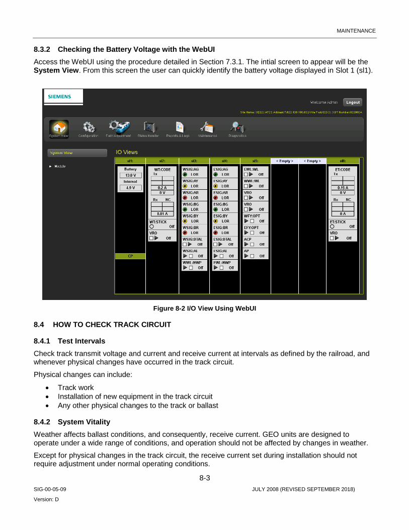
MAINTENANCE
8-3 SIG-00-05-09 JULY 2008 (REVISED SEPTEMBER 2018)
Version: D
8.3.2 Checking the Battery Voltage with the WebUI Access the WebUI using the procedure detailed in Section 7.3.1. The intial screen to appear will be the System View. From this screen the user can quickly identify the battery voltage displayed in Slot 1 (sl1).
Figure 8-2 I/O View Using WebUI
8.4 HOW TO CHECK TRACK CIRCUIT
8.4.1 Test Intervals Check track transmit voltage and current and receive current at intervals as defined by the railroad, and whenever physical changes have occurred in the track circuit.
Physical changes can include:
• Track work • Installation of new equipment in the track circuit • Any other physical changes to the track or ballast
8.4.2 System Vitality Weather affects ballast conditions, and consequently, receive current. GEO units are designed to operate under a wide range of conditions, and operation should not be affected by changes in weather.
Except for physical changes in the track circuit, the receive current set during installation should not require adjustment under normal operating conditions.

MAINTENANCE
8-4 SIG-00-05-09 JULY 2008 (REVISED SEPTEMBER 2018)
Version: D
8.4.3 Procedure for Checking Track Circuits Refer to the How to Set Track Module Receive Current and How to Set Track Module Voltage and Current Limit procedures in SECTION 7.
8.5 HOW TO CHECK SIGNAL LAMP PARAMETERS
8.5.1 Color Light Lamp Voltage See How to Set Lamp Voltage for Color Light Signal Heads in SECTION 7.
8.5.2 Search Light Signal See How to Set Search Light Parameters in SECTION 7.
8.6 GEO MODULE/MEF REPLACEMENT TEST PROCEDURES The following procedures provide minimum guidelines for testing a GEO unit after replacing a module or upgrading a module MEF (module executable file). These procedures outline the minimum testing that must be done to verify the GEO system and software are functioning as intended. The railroad and/or authority may require additional testing to be performed in support of changing the module or MEF(s).
8.6.1 Units Effected All GEO modules and corresponding MEF(s)
8.6.2 Locations All applicable GEO locations.
WARNING REPLACING A MODULE OR MEF WILL RESULT IN THE MODULE BEING RESET, THEREFORE, THE RAILROAD AND/OR AUTHORITY MUST MAKE THE NECESSARY ARRANGEMENTS TO ASSURE THE SAFE MOVEMENT OF TRAINS PRIOR TO REPLACING AND VERIFYING THE NEWLY INSTALLED MODULE OR MEF(S). IT IS RECOMMENDED THAT A QUALIFIED RAILROAD EMPLOYEE PERFORM THE TEST PROCEDURES HEREIN.
NOTE The use of WebUI (CPU III) or DT (CPU II+) is required.

MAINTENANCE
8-5 SIG-00-05-09 JULY 2008 (REVISED SEPTEMBER 2018)
Version: D
8.6.3 Applicable Documents Location Circuit Plans: these plans should contain the field configuration and/or MEF information for the location. Siemens recommends consulting with railroad officials to verify current field configuration and approved module MEF versions.
• Railroad/User Maintenance and Testing Regulations and Instructions. (All applicable test procedures, standards, and operating instructions.)
• Railroad/User Software Configuration Guidelines, where applicable. • Applicable site-specific documentation • Track plans • Aspect charts • Railroad software configuration information
8.7 TEST PROCEDURE 1: GEO TRACK MODULE / MEF REPLACEMENT Use the following test procedure when replacing a GEO Track Module or Track Module MEF.
8.7.1 Required Tools
• Laptop computer with Siemens DT, Diagnostic Terminal utility installed or WebUI access. • GEO Diagnostic Terminal (DT) Handbook (Document No.SIG-00-04-17). • CPU III for GEO and WayConneX (Document No. SIG-00-15-04) • Triplett 2000 or equivalent. • 9-pin Female to Male straight through RS-232 Serial Cable. • 0.06 ohm test shunt.
8.7.2 Procedure for CPU II+ Using DT to Check Track Module / Replace MEF 1. Connect the laptop to the DIAG (CP) port on the CPU II+ module. Launch the DT. 2. Using the DT utility, verify and record the transmit amps, transmit volts, and receive amps for the
GEO Track Module to be replaced or updated. (See example below) 3. Verify the Track Module field configurable options, V(TX) and current limit. (See example below) 4. Verify the MEF version currently in use on the Track Module by selecting Software Information
under the “VIEW” tab. a. Scroll through the system information display to locate the Track Module MEF information.
Record the MEF version.
WARNING REPLACING A TRACK MODULE OR MODULE MEF WILL RESULT IN A MODULE RESET. DURING THIS INITIALIZATION PROCESS, THE GEO UNIT DOES NOT HAVE CONTROL OF THE ASSOCIATED TRACK. TAKE ADEQUATE PRECAUTIONS PER RAILROAD SAFETY AND OPERATING RULES PERTAINING TO THE SIGNAL SYSTEM.
5. If replacing MEF only, go to step 10. 6. Remove the GEO Track Module to be replaced and observe the position of the receiver jumper.

MAINTENANCE
8-6 SIG-00-05-09 JULY 2008 (REVISED SEPTEMBER 2018)
Version: D
7. Prior to installing the new GEO Track Module, install the receiver jumper in the same position as it was on the previous module. Also verify the module hardware version. (Hardware version label located on backside of module on or near module serial number label.)
8. Install the new Track Module. 9. Verify that the “Health” LED on the new Track Module is flashing at the proper rate (see chapter
3). Additionally, the “coded track” module label should turn green on the DT main display if the Track Module is communicating with the CPU module. If indications appear as stated, proceed to step 13.
NOTE If the health LED indicates a problem, the associated Track Module label is displayed red, or the CPU Module and/or Track Module display indicates an error, check the Track Module MEF version as described in step 4 above.
10. If the MEF is to be changed, connect the laptop to the diagnostic port on the Track Module that will receive the MEF update.
11. Install the MEF as follows: b. Click the COMM button or menu, then select Install Software. c. A text box appears displaying boot messages until the Setup Program menu is displayed. d. Press the F4 function key on the PC keyboard or click the F4 button on the display to start
the MEF change process. e. Select the correct MEF file for the module. f. Once the loading of the new MEF starts, the bar at the base of the text box shows
progress. g. When the new MEF is completely loaded the text box will return to the Setup Program
menu.
NOTE If the module fails to reboot, or reboots and re-enters the Setup Program, check the boot messages to see if the correct MEF is listed. If not, repeat the MEF download process by clicking the MEF button or pressing F4.
NOTE If the unit is without an MEF, Click the COMM button and select Reset Module from the menu. If “No Valid MEF” is displayed in the Text Terminal screen, then respond to “Change module setup (Y/N)?” by typing a “Y” from the keyboard, and then repeat steps c through e above.
h. Select EXIT to reboot the module and exit the Setup Program. i. After observing that the module is rebooting, select EXIT again to close the text box. j. Wait until the GEO reboot is complete. Move the DB9 serial cable to the CPU module
DIAG (CP) port if needed and reconnect DT. k. Right click on the label for the module just updated (label should be green), then select
the Module Information function to check that the new MEF installation was successful.

MAINTENANCE
8-7 SIG-00-05-09 JULY 2008 (REVISED SEPTEMBER 2018)
Version: D
NOTE Siemens recommends recording this software change on the location circuit plans.
12. Verify the “Health” LED on the updated Track Module is flashing at the proper flash rate (see chapter 3).
13. Using the GEO DT, verify the loaded MEF name and CRC number (see step 4 above). 14. Depending on track and weather conditions it may be necessary to readjust the GEO track circuit
to meet manufacture’s recommended operating parameters. See tables below for recommended receive current settings.
15. Verify the Track Module is transmitting and receiving vital and non-vital track codes by observing TX and RX track code displays on the Track Module.
16. Perform an operational test of the track circuit by applying a 0.06-ohm shunt on at least one end of the effective track circuit and verify the loss of receive track codes and receive amps.
17. Simulate broken rail by opening at least one track connection (test link) in the circuit and observe loss of receive track codes and receive amps. With the track lead open an ‘F’ indication may be displayed on the Track Module TX code display.
18. Remove all test equipment, track shunts, ensure all connections are tight, and extinguish signal lamps where applicable and restore the signal system to service.
8.7.3 Procedure for CPU III Using WebUI to Check Track Module / Replace MEF 1. Connect the laptop via an Ethernet cable to the Laptop port. Launch the WebUI. 2. Using the WebUI I/O Views screen, verify and record the transmit amps, transmit volts, and
receive amps for the GEO Track Module to be replaced or updated. 3. Verify the Track Module field configurable options, V(TX) and current limit. (See example below) 4. Verify the MEF version currently in use on the Track Module by selecting System View > Module
> Versions. Find the correct slot and record the MEF Version (under the column labeled Name).
Figure 8-3 MEF Version Check Using WebUI

MAINTENANCE
8-8 SIG-00-05-09 JULY 2008 (REVISED SEPTEMBER 2018)
Version: D
WARNING REPLACING A TRACK MODULE OR MODULE MEF WILL RESULT IN A MODULE RESET. DURING THIS INITIALIZATION PROCESS, THE GEO UNIT DOES NOT HAVE CONTROL OF THE ASSOCIATED TRACK. TAKE ADEQUATE PRECAUTIONS PER RAILROAD SAFETY AND OPERATING RULES PERTAINING TO THE SIGNAL SYSTEM.
5. If replacing MEF only, go to step 10. 6. Remove the GEO Track Module to be replaced and observe the position of the receiver jumper. 7. Prior to installing the new GEO Track Module, install the receiver jumper in the same position as
it was on the previous module. Also verify the module hardware version. (Hardware version label located on backside of module on or near module serial number label.)
8. Install the new Track Module. 9. Verify that the “Health” LED on the new Track Module is flashing at the proper rate (see chapter
3). Additionally, the slot label should turn green on the IO Views display if the Track Module is communicating with the CPU module. If indications appear as stated, proceed to step 10.
NOTE If the health LED indicates a problem, the associated Track Module label is displayed red, or the CPU Module and/or Track Module display indicates an error, check the Track Module MEF version as described in step 4 above.
10. If the MEF is to be changed, connect the CPU III to the diagnostic port on the Track Module that will receive the MEF update via a serial cable.
11. Install the MEF as follows: a. First, unlock the parameters for editing: the Unlock button must be selected and then
either the SEL or NAV button on the front of the CPU to confirm user presence. b. The WebUI will then notify the user to check the serial port connection before uploading.
Figure 8-4 Check Serial Port Connection

MAINTENANCE
8-9 SIG-00-05-09 JULY 2008 (REVISED SEPTEMBER 2018)
Version: D
c. Select OK to continue. The WebUI will then display the following message. Select OK to continue.
Figure 8-5 CPU/Module Reboot Warning
d. The menu for updating the Track Module MEF will now be available. Select Change MEF to continue. The user can also note the current MEF on this screen.
Figure 8-6 Change Track Module MEF
e. Once Change MEF has been selected, the WebUI will ask to confirm deletion of the current MEF (Erase the MEF (Y/N)?). Select Yes to continue.
f. A Browse button will then appear allowing the user to navigate to the desired MEF.
Figure 8-7 Browse for Track Module MEF

MAINTENANCE
8-10 SIG-00-05-09 JULY 2008 (REVISED SEPTEMBER 2018)
Version: D
g. Once the correct file is selected, the WebUI will begin the upload. A status bar will appear indicating upload progress.
Figure 8-8 Track Module MEF Upload Status
h. At the end of the upload the WebUI will display the following message: Uploaded files successfully. The user can then select the Exit Setup option located above the progress bar.
NOTE If the module fails to reboot, or reboots and re-enters the Setup Program, check the boot messages to see if the correct MEF is listed. If not, repeat the MEF download process by clicking the MEF button or pressing F4.
NOTE If the unit is without an MEF, Click the COMM button and select Reset Module from the menu. If “No Valid MEF” is displayed in the Text Terminal screen, then respond to “Change module setup (Y/N)?” by typing a “Y” from the keyboard, and then repeat steps c through e above.
l. Wait until the GEO reboot is complete, then return to the System View menu and select Version to check that the new MEF installation was successful.
NOTE Siemens recommends recording this software change on the location circuit plans.
12. Verify the “Health” LED on the updated Track Module is flashing at the proper flash rate (see chapter 3).
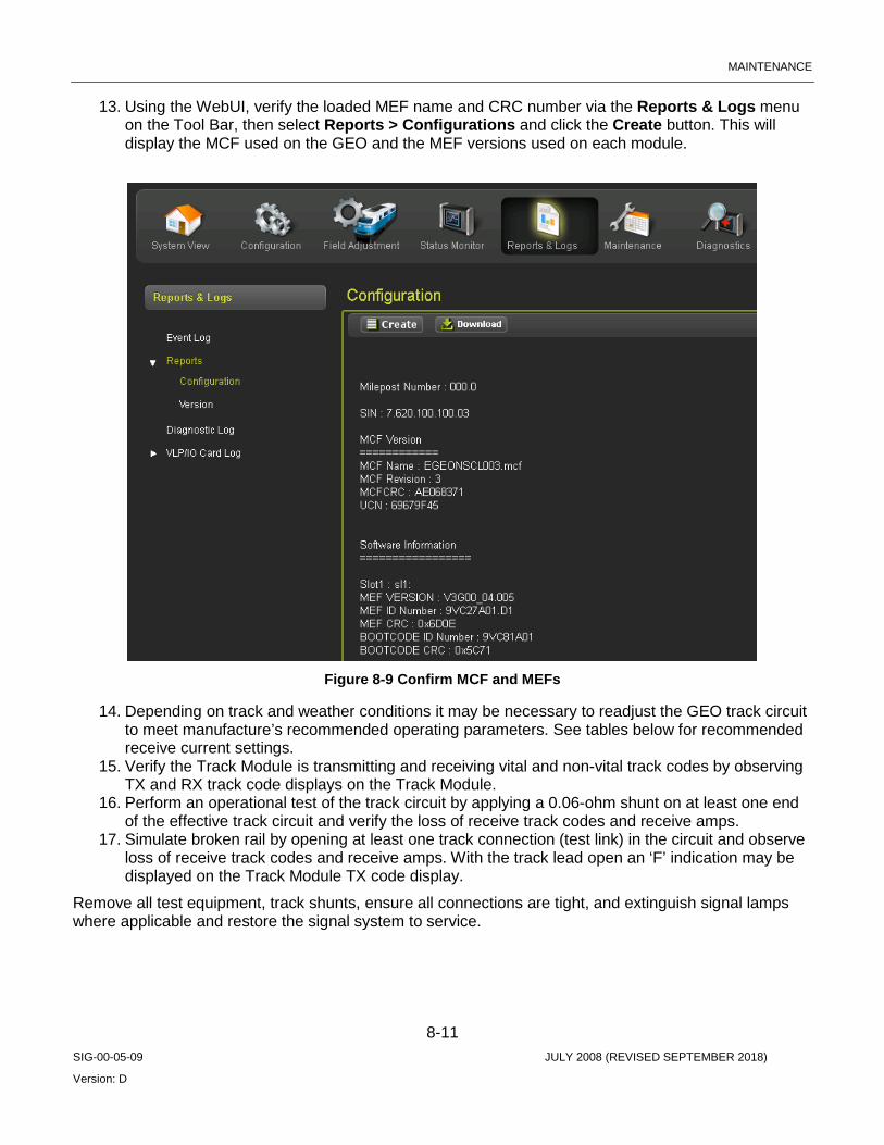
MAINTENANCE
8-11 SIG-00-05-09 JULY 2008 (REVISED SEPTEMBER 2018)
Version: D
13. Using the WebUI, verify the loaded MEF name and CRC number via the Reports & Logs menu on the Tool Bar, then select Reports > Configurations and click the Create button. This will display the MCF used on the GEO and the MEF versions used on each module.
Figure 8-9 Confirm MCF and MEFs
14. Depending on track and weather conditions it may be necessary to readjust the GEO track circuit to meet manufacture’s recommended operating parameters. See tables below for recommended receive current settings.
15. Verify the Track Module is transmitting and receiving vital and non-vital track codes by observing TX and RX track code displays on the Track Module.
16. Perform an operational test of the track circuit by applying a 0.06-ohm shunt on at least one end of the effective track circuit and verify the loss of receive track codes and receive amps.
17. Simulate broken rail by opening at least one track connection (test link) in the circuit and observe loss of receive track codes and receive amps. With the track lead open an ‘F’ indication may be displayed on the Track Module TX code display.
Remove all test equipment, track shunts, ensure all connections are tight, and extinguish signal lamps where applicable and restore the signal system to service.

MAINTENANCE
8-12 SIG-00-05-09 JULY 2008 (REVISED SEPTEMBER 2018)
Version: D
Table 8-1 Track Module Receive Currents
Ballast Conditions DT RX Current Target Reading Frozen Ballast Approx. 1350 mA
Dry Ballast Approx. 1150 mA
Wet Ballast Approx. 850 mA
Table 8-2 Track Circuit RX Jumper Adjustment Table
Jumper Position Assigned Resistance Value
Total Resistance w/Jumper in Position
Resistance Calculation
J-6 Zero Ohms (0) J-6 = Zero (0) Ohms J6 only
J-5 0.15 Ohms J-5 = 0.15 Ohms J6+J5
J-4 0.15 Ohms J-4 = 0.30 Ohms J6+J5+J4
J-3 0.20 Ohms J-3 = 0.50 Ohms J6+J5+J4+J3
J-2 0.33 Ohms J-2 = 0.83 Ohms J6+J5+J4+J3+J2
NOTE The final RX adjustment of the GEO track circuit is equal to the total resistance shown for the assigned jumper position. Total resistance is based on the sum of all prior resistances beginning with position J-6. For example if the jumper is left in position J-4 the added total resistance to the RX adjustment is equal to 0.30 ohms. To decrease the RX amp reading move the jumper from J-4 to J-3 or J-2, to increase the RX amp reading move the jumper from J-4 to J-5 or J-6.
8.8 TEST PROCEDURE 2: CPU MODULE VLP/CP MEF REPLACEMENT Use the following procedure when replacing a GEO CPU Module or the CPU Module MEFs.
8.8.1 Required Tools
• Laptop computer with Siemens Diagnostic Terminal (DT) utility installed or WebUI access • CPU III for GEO and WayConneX (Document No. SIG-00-15-04) • GEO Diagnostic Terminal (DT) Handbook (Document No. SIG-00-04-17) • 9-pin Female to Male straight through RS-232 Serial Cable.
NOTE Please ensure the use of the corresponding VLP and CP MEFs as identified by Siemens Mobility. Refer to the Railroad/User Software Configuration database to ensure proper MEF revision levels.
MAINTENANCE
8-13 SIG-00-05-09 JULY 2008 (REVISED SEPTEMBER 2018)
Version: D
8.8.2 Replacing the CPU VLP/CP MEF via DT (CPU II+) 1. Connect the laptop to the DIAG (CP) port on the GEO CPU module. 2. Verify the MEF versions currently in use on the CPU module by selecting Software Information
under the “VIEW” tab. a. Scroll through the system information display to locate the CPU module MEF information.
WARNING REPLACING A MODULE OR MODULE MEF WILL RESULT IN A MODULE RESET. DURING THIS INITIALIZATION PROCESS, THE GEO UNIT DOES NOT HAVE CONTROL OF THE SIGNAL SYSTEM. TAKE ADEQUATE PRECAUTIONS PER RAILROAD SAFETY AND OPERATING RULES PERTAINING TO THE SIGNAL SYSTEM.
3. If replacing MEFs only, go to step 6. 4. Disconnect the serial cable, remove the CPU Module and install the new CPU Module. 5. Verify the MEF versions of the new module (repeat steps 1 & 2). 6. If the MEFs are to be replaced, connect the laptop to the left VLP port to update the Vital Logic
Processor MEF and the right DIAG (CP) port to update the Communications Processor MEF. 7. Install the each MEF as follows:
a. Click the COMM button or menu, then select Install Software. b. A text box appears displaying boot messages until the Setup Program menu is displayed. c. Press the F4 function key on the PC keyboard or click the F4 button on the display to start
the MEF change process. d. Select the correct MEF file for the module. e. Once the loading of the new MEF starts, the bar at the base of the text box shows
progress. f. When the new MEF is completely loaded the text box will return to the Setup Program
menu.
NOTE If the module fails to reboot, or reboots and re-enters the Setup Program, check the boot messages to see if the correct MEF is listed. If not, repeat the MEF download process by clicking the MEF button or pressing F4.
NOTE If the unit is without an MEF, Click the COMM button and select “Reset Module” from the menu. If “No Valid MEF” is displayed in the Text Terminal screen, then respond to “Change module setup (Y/N)?” by typing a “Y” from the keyboard, and then repeat steps c through e above.
a. Select EXIT to reboot the module and exit the Setup Program. b. After observing that the module is rebooting, select EXIT again to close the text box. c. Wait until the GEO reboot is complete. Move the DB9 serial cable to the CPU module
DIAG (CP) port if needed and reconnect DT.

MAINTENANCE
8-14 SIG-00-05-09 JULY 2008 (REVISED SEPTEMBER 2018)
Version: D
d. Right click on the CPU module label (label should be green), then select the Module Information function to check that the new MEF installation was successful.
NOTE Siemens recommends recording this software change on the location circuit plans.
8. Verify that all health and status LEDs on the CPU module are indicating properly (see Primary Equipment Description).
9. Verify the MCF name is scrolling in the CPU display. 10. Using the GEO DT, verify the loaded VLP and CP MEF names and CRC numbers (see step 2
above). 11. Using the DT, verify that all required GEO modules are in session and communicating with the
CPU module by observing the CPU status/summary log. In addition, ensure each module displays a green module label on the main DT status display for the GEO unit. Any modules that show a red module label may be an indication that the module is not communicating with the CPU module.
12. Momentarily remove each module, one at a time, replacing one before removing the next, and observe loss of communication with the CPU module.
13. If the GEO unit is in an interlocking and or control point, verify that at least one indication can be sent and one control can be received and executed per the given application from the central office to the GEO unit, (i.e. vital switch and or signal/route request). For distributed GEO systems (multiple units), ensure such request(s) include logic execution associated with each GEO unit.
14. If the GEO unit is connected to signal equipment through echelon ports (other than the Local Control Panel), then verify that at least one input to the GEO unit and one output from the GEO unit is functional.
15. For all locations utilizing a ULCP, (Universal Local Control Panel), verify the functionality of the ULCP by placing the location in local control and generating requests to the GEO system from the ULCP. Verify that corresponding ULCP indications are properly displayed.
16. For distributed GEO systems, momentarily disconnect the Echelon connection between the GEO units and verify the system responds accordingly, (e.g. display a signal for a given route spanning more than one GEO unit; remove the Echelon connection between GEO units and observe that the clear signal displays stop). In addition, ensure each ATCS session displays a green color banner on the DT ATCS Communications status display for the GEO unit.
17. Using the DT, verify the CPU module is recording events from each module as well as itself.

MAINTENANCE
8-15 SIG-00-05-09 JULY 2008 (REVISED SEPTEMBER 2018)
Version: D
8.8.3 Replacing the CPU VLP/CP MEF via the WebUI 1. Connect the laptop via an Ethernet cable to the Laptop port. Launch the WebUI (reference
section 7.3.1). 2. Verify the MEF version currently in use by selecting System View > Module > Versions. Find
the correct slot and record the CPU MEF Version (under the column labeled Name).
WARNING REPLACING A MODULE OR MODULE MEF WILL RESULT IN A MODULE RESET. DURING THIS INITIALIZATION PROCESS, THE GEO UNIT DOES NOT HAVE CONTROL OF THE SIGNAL SYSTEM. TAKE ADEQUATE PRECAUTIONS PER RAILROAD SAFETY AND OPERATING RULES PERTAINING TO THE SIGNAL SYSTEM.
3. If replacing MEFs only, go to step 6. 4. Disconnect the Ethernet cable, remove the CPU Module, and install the new CPU Module. 5. Verify the MEF versions of the new module (repeat steps 1 & 2). 6. If the MEFs are to be replaced, connect the laptop to the Laptop port to update the Vital Logic
Processor MEF and the Communications Processor MEF. 7. Install the each MEF as follows:
a. Click the Maintenance icon from the Tool Bar. b. From the left side menu, select either the CP MEF or VLP MEF. c. To confirm local user presence, click the Unlock button, confirm, then immediately
following, press either the SEL or NAV button on the front of the CPU III. d. Once unlocked (screen will display Unlock Successful. System is in edit mode now.),
click the Browse button and navigate to the desired MEF file. e. After selecting the correct file, click the Update button. f. Once the loading of the new MEF starts, an Uploading Status bar will show progress. g. Prior to finishing the upload the WebUI will display the message shown in Figure 8-10.
Figure 8-10 Reboot Required

MAINTENANCE
8-16 SIG-00-05-09 JULY 2008 (REVISED SEPTEMBER 2018)
Version: D
h. Select OK to continue. The new MEF is now completely loaded and the screen will display the message shown in Figure 8-11. The module will then proceed to reboot.
Figure 8-11 CP MEF Upload Successful
NOTE If the module fails to reboot, or reboots and re-enters the Setup Program, check the boot messages to see if the correct MEF is listed. If not, repeat the MEF download process by clicking the MEF button or pressing F4.
NOTE If the unit is without an MEF, Click the COMM button and select “Reset Module” from the menu. If “No Valid MEF” is displayed in the Text Terminal screen, then respond to “Change module setup (Y/N)?” by typing a “Y” from the keyboard, and then repeat steps c through e above.
i. Using the WebUI, verify the loaded MEF name and CRC number via the Reports & Logs menu on the Tool Bar, then select Reports > Configurations and click the Create button. This will display the MEF used on the GEO and the MEF versions used on each module.

MAINTENANCE
8-17 SIG-00-05-09 JULY 2008 (REVISED SEPTEMBER 2018)
Version: D
NOTE Siemens recommends recording this software change on the location circuit plans.
8. Verify that all health and status LEDs on the CPU module are indicating properly (see Primary Equipment Description).
9. Verify the MCF name is scrolling in the CPU display. 10. Using the GEO DT, verify the loaded VLP and CP MEF names and CRC numbers (see step g
above). 11. Using the WebUI, verify that all required GEO modules are in session and communicating with
the CPU module by observing the IO Views. In addition, ensure each module displays a green module label on the IO View display for the GEO unit. Any modules that show a red module label may be an indication that the module is not communicating with the CPU module.
12. Momentarily remove each module, one at a time, replacing one before removing the next, and observe loss of communication with the CPU module.
13. If the GEO unit is in an interlocking and or control point, verify that at least one indication can be sent and one control can be received and executed per the given application from the central office to the GEO unit, (i.e. vital switch and or signal/route request). For distributed GEO systems (multiple units), ensure such request(s) include logic execution associated with each GEO unit.
14. If the GEO unit is connected to signal equipment through echelon ports (other than the Local Control Panel), then verify that at least one input to the GEO unit and one output from the GEO unit is functional.
15. For all locations utilizing a ULCP, (Universal Local Control Panel), verify the functionality of the ULCP by placing the location in local control and generating requests to the GEO system from the ULCP. Verify that corresponding ULCP indications are properly displayed.
16. For distributed GEO systems, momentarily disconnect the Echelon connection between the GEO units and verify the system responds accordingly, (e.g. display a signal for a given route spanning more than one GEO unit; remove the Echelon connection between GEO units and observe that the clear signal displays stop). In addition, ensure each ATCS session displays a green color banner on the DT ATCS Communications status display for the GEO unit.
17. Using the WebUI, verify the CPU module is recording events (Event Log) from each module as well as itself.
Upon completion of this testing remove all test equipment, restore the ULCP to the office/remote position, and return control of the location to the railroad dispatcher/operator.
8.9 TEST PROCEDURE 3: GEO I/O MODULE/MEF REPLACEMENT WITH THE DT TOOL Use the following procedure when replacing a GEO I/O Module or the module MEF.
8.9.1 Required Tools
• Laptop computer with Siemens Diagnostic Terminal (DT) utility installed or Laptop computer with access to WebUI
• 9-pin Female to Male straight through RS-232 Serial Cable or Ethernet cable
1. Connect the laptop to the DIAG (CP) port on the GEO CPU module. Launch the DT utility or the Web UI.

MAINTENANCE
8-18 SIG-00-05-09 JULY 2008 (REVISED SEPTEMBER 2018)
Version: D
2. Verify the MEF version currently in use on the GEO module to be updated/replaced by selecting Software Information under the “VIEW” tab. Scroll through the system information display to locate the module MEF information.
WARNING REPLACING A MODULE OR MODULE MEF WILL RESULT IN A MODULE RESET. DURING THIS SOFTWARE UPGRADE, THE GEO UNIT DOES NOT HAVE CONTROL OF THE SIGNAL SYSTEM. TAKE ADEQUATE PRECAUTIONS PER RAILROAD SAFETY AND OPERATING RULES PERTAINING TO THE SIGNAL SYSTEM.
3. If replacing MEF only, go to step 5. 4. Remove the GEO I/O Module and install the new GEO I/O Module. 5. If the MEF is to be replaced, connect the laptop to the diagnostic port on the module that will
receive the MEF update. 6. Install the MEF as follows:
a. Click the COMM button or menu, then select Install Software. b. A text box appears displaying boot messages until the Setup Program menu is displayed. c. Press the F4 function key on the PC keyboard or click the F4 button on the display to start
the MEF change process. d. Select the correct MEF file for the module. e. Once the loading of the new MEF starts, the bar at the base of the text box shows
progress. f. When the new MEF is completely loaded the text box will return to the Setup Program
menu.
NOTE If the module fails to reboot, or reboots and re-enters the Setup Program, check the boot messages to see if the correct MEF is listed. If not, repeat the MEF download process by clicking the MEF button or pressing F4.
NOTE If the unit is without an MEF, click the COMM button and select Reset Module from the menu. If “No Valid MEF” is displayed in the Text Terminal screen, then respond to “Change module setup (Y/N)?” by typing a “Y” from the keyboard, and then repeat steps c through e above.
g. Select EXIT to reboot the module and exit the Setup Program. h. After observing that the module is rebooting, select EXIT again to close the text box. i. Wait until the GEO reboot is complete. Move the DB9 serial cable to the CPU module
DIAG (CP) port if needed and reconnect DT. j. Right click on the label for the module just updated (label should be green), then select
the Module Information function to check that the new MEF installation was successful.

MAINTENANCE
8-19 SIG-00-05-09 JULY 2008 (REVISED SEPTEMBER 2018)
Version: D
NOTE Siemens recommends recording this software change on the location circuit plans.
7. Verify the “Health” LED on the updated module is flashing at the proper flash rate (see chapter 3). 8. Using the GEO DT, verify the loaded MEF name and CRC number (see step 2 above). 9. Open the summary log under the “HIST” tab on the respective module and verify the module has
re-established session with the VLP by observing the presence of the Rx Session Established message.
10. Open the CP and VLP summary log on the CPU module and confirm Rx Session has been re-established with the VLP. (See samples of CP and VLP summary log below.)
11. Exit the DT utility. 12. Remove the laptop from the GEO unit and restore the signal system to service.
8.9.2 Replace I/O Module MEF via the WebUI Follow procedure outlined in Section 8.7.3 for Replacing Track Module MEF, using the same process but connecting the serial cable to the I/O module and selecting the correct MEF for the I/O Module to upload.
8.10 TEST PROCEDURE 4: SEARCH LIGHT MODULE / MEF REPLACEMENT Use the following procedure when replacing a GEO Search Light Module or the module MEF.
8.10.1 Required Tools
• Laptop computer with Siemens Diagnostic Terminal (DT) utility installed. • GEO Diagnostic Terminal (DT) Handbook (Document No. SIG-00-04-17). • 9-pin Female to Male straight through RS-232 Serial Cable. • 9-pin Female to 4-pin Female RS-232 Adaptor for use with the Search Light Module diagnostic
connector, J4.
1. Connect the laptop to the DIAG (CP) port on the GEO CPU module. Launch the DT utility. 2. Verify the MEF version currently in use on the GEO Search Light Module to be updated/replaced
by selecting Software Information under the “VIEW” tab. Scroll through the system information display to locate the module MEF information.
3. After verifying the existing MEF, change the module verbosity to level 2. Do this by right-clicking on the module label and selecting Set Verbosity on the menu. When the Verbosity window appears, drag the cursor to the second position, and click the SET button.
WARNING REPLACING A MODULE MEF WILL RESULT IN A MODULE RESET. DURING THIS SOFTWARE UPGRADE, THE GEO UNIT DOES NOT HAVE CONTROL OF THE SIGNAL SYSTEM. TAKE ADEQUATE PRECAUTIONS PER RAILROAD SAFETY AND OPERATING RULES PERTAINING TO THE SIGNAL SYSTEM.
4. If replacing the MEF only, go to step 6. 5. Remove the Search Light Module and replace it with the new Search Light Module.

MAINTENANCE
8-20 SIG-00-05-09 JULY 2008 (REVISED SEPTEMBER 2018)
Version: D
6. To replace the MEF, connect the laptop to J4 on the GEO Search Light Module using the RS-232 Adaptor cable.
7. Install the MEF as follows: a. Click the COMM button or menu, then select Install Software. b. A text box appears displaying boot messages until the Setup Program menu is displayed. c. Press the F4 function key on the PC keyboard or click the F4 button on the display to start the
MEF change process. d. Select the correct MEF file for the module. e. Once the loading of the new MEF starts, the bar at the base of the text box shows progress. f. When the new MEF is completely loaded the text box will return to the Setup Program menu.
NOTE If the module fails to reboot, or reboots and re-enters the Setup Program, check the boot messages to see if the correct MEF is listed. If not, repeat the MEF download process by clicking the MEF button or pressing F4.
NOTE If the unit is without an MEF, Click the COMM button and select Reset Module from the menu. If “No Valid MEF” is displayed in the Text Terminal screen, then respond to “Change module setup (Y/N)?” by typing a “Y” from the keyboard, and then repeat steps c through e above.
g. Select EXIT to reboot the module and exit the Setup Program. h. After observing that the module is rebooting, select EXIT again to close the text box. i. Wait until the GEO reboot is complete. Move the DB9 serial cable to the CPU module DIAG
(CP) port if needed and reconnect DT. j. Right click on the label for the module just updated (label should be green), then select the
Module Information function to check that the new MEF installation was successful.
NOTE Siemens recommends recording this software change on the location circuit plans.
8. Using the GEO DT, verify the loaded MEF name and CRC number (see steps 1 & 2 above). 9. Verify the “health” LED on the Search Light module is flashing at the proper flash rate (see
chapter 3). Additionally, the module label will turn green when displayed on the DT indicating that the module and newly installed MEF is communicating with the CPU module, as shown below.
10. Open the summary log under the “HIST” tab on the respective module and verify the module has re-established session with the VLP by observing the presence of the Rx Session Established message.
11. Open the CP and VLP summary log on the CPU module and confirm Rx Session has been re-established with the VLP. (see samples of CP and VLP summary log below)
12. Open the status log under the “HIST” tab on the respective module. 13. Verify the module has completed and passed the Search Light mechanism self test for both
channel 1 and channel 2 (see below). 14. Change the module verbosity setting back to level 1 (minimum).
MAINTENANCE
8-21 SIG-00-05-09 JULY 2008 (REVISED SEPTEMBER 2018)
Version: D
15. Exit the DT utility. 16. Disconnect the laptop from the GEO unit. 17. Restore the signal system to service.
8.10.2 Replace Search Light Module MEF via the WebUI Follow procedure outlined in Section 8.7.3 for Replacing Track Module MEF, using the same process but connecting the serial cable to the Search Light module and selecting the correct MEF for the Search Light Module to upload.

MAINTENANCE
8-22 SIG-00-05-09 JULY 2008 (REVISED SEPTEMBER 2018)
Version: D
This Page Intentionally Left Blank
TRACK CIRCUIT TROUBLESHOOTING GUIDE
9-1 SIG-00-05-09 JULY 2008 (REVISED SEPTEMBER 2018)
Version: D
SECTION 9 TROUBLESHOOTING
9.0 OVERVIEW This chapter covers the following topics:
• Warnings and precautions • Tools and equipment needed • Troubleshooting notes and tips • Typical symptoms • Standard troubleshooting procedure • Troubleshooting using flowcharts
WARNING TROUBLESHOOTING MAY INTERFERE WITH THE OPERATION OF THE SIGNAL SYSTEM. BEFORE TROUBLESHOOTING THE GEO SYSTEM, OBTAIN PERMISSION FROM THE DISPATCHER PER RAILROAD OPERATING RULES.
9.1 ESD PRECAUTIONS Electrostatic Discharge, or ESD, can damage electronic circuitry, particularly low voltage components found on GEO modules. Therefore, Siemens encourages its customers to adopt the following procedures to lessen the likelihood of equipment damage in the field due to ESD:
• Ground yourself before touching a chassis, modules, or components. • Remove modules from the chassis by the ejector lever only. • Handle circuit boards by the edges only. • Never physically touch the circuit board contact fingers or allow these fingers to come in contact
with an insulator (such as plastic or rubber). • When not in use, place circuit boards in approved static-shielding bags, contact fingers first.
Remove circuit boards from static-shielding bags by grasping the ejector lever or the edge of the board only. Each bag should include a caution label on the outside indicating static-sensitive contents.
• Cover workbench surfaces used for repair of electronic equipment with static dissipative workbench matting.
• Use only anti-static cushioning material in equipment shipping and storage containers.
9.2 TOOLS AND EQUIPMENT NEEDED Have the following test equipment and tools available for troubleshooting:
• Digital multimeter such as Fluke 27 or 87 or equivalent • Spare modules for GEO • Spare parts as needed (fuses, surge arresters, batteries, etc.) • Common hand tools

TRACK CIRCUIT TROUBLESHOOTING GUIDE
9-2 SIG-00-05-09 JULY 2008 (REVISED SEPTEMBER 2018)
Version: D
NOTE Make sure instruments such as multimeters are calibrated to railroad standards. Follow railroad guidelines regarding spare modules and parts.
9.3 STANDARD TROUBLESHOOTING PROCEDURE A standard troubleshooting procedure has been adopted to ensure a systematic approach to all problems relating to signal control systems.
The standard procedure is listed below, tailored to the GEO equipment:
Table 9-1 GEO Troubleshooting Procedure
Step Action Tips
1
Identify the trouble symptom. Get as much information as possible from the report source.
Verify the problem. Check to verify that the symptom reported still exists. Check with the dispatcher, specialist, and train crews.
Ask questions, such as:
• Exactly what is the problem? • What was going on when the problem occurred? • Was the weather a factor? Could it have affected ballast conditions
or damaged surge protection devices? • Was anything else going on at the time, such as another problem
that could be related? • Has there been recent track work in the area?
2
Sectionalize the problem. Look at what is being reported to be in trouble.
Cut the circuit or system in half by observing GEO indicator LEDs and take readings. Try to determine which half contains the problem.
Did something change? Has this system worked properly before or is this a startup problem? If the system used to work properly, has anything changed since then? Have there been any hardware changes or wiring changes?
Use the flowcharts. Follow a logical procedure and keep a record of steps and results. After trying something, be sure to restore modules and connections that do not clear up the problem.
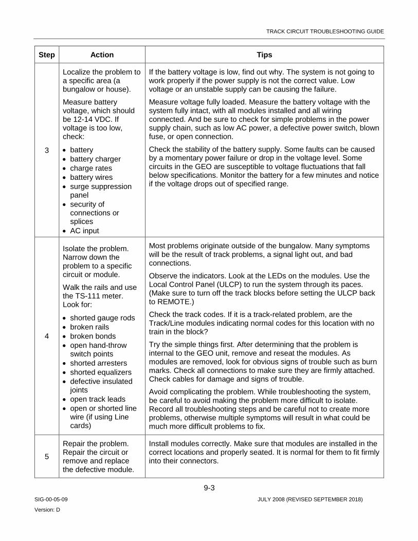
TRACK CIRCUIT TROUBLESHOOTING GUIDE
9-3 SIG-00-05-09 JULY 2008 (REVISED SEPTEMBER 2018)
Version: D
Step Action Tips
3
Localize the problem to a specific area (a bungalow or house).
Measure battery voltage, which should be 12-14 VDC. If voltage is too low, check:
• battery • battery charger • charge rates • battery wires • surge suppression
panel • security of
connections or splices
• AC input
If the battery voltage is low, find out why. The system is not going to work properly if the power supply is not the correct value. Low voltage or an unstable supply can be causing the failure.
Measure voltage fully loaded. Measure the battery voltage with the system fully intact, with all modules installed and all wiring connected. And be sure to check for simple problems in the power supply chain, such as low AC power, a defective power switch, blown fuse, or open connection.
Check the stability of the battery supply. Some faults can be caused by a momentary power failure or drop in the voltage level. Some circuits in the GEO are susceptible to voltage fluctuations that fall below specifications. Monitor the battery for a few minutes and notice if the voltage drops out of specified range.
4
Isolate the problem. Narrow down the problem to a specific circuit or module.
Walk the rails and use the TS-111 meter. Look for:
• shorted gauge rods • broken rails • broken bonds • open hand-throw
switch points • shorted arresters • shorted equalizers • defective insulated
joints • open track leads • open or shorted line
wire (if using Line cards)
Most problems originate outside of the bungalow. Many symptoms will be the result of track problems, a signal light out, and bad connections.
Observe the indicators. Look at the LEDs on the modules. Use the Local Control Panel (ULCP) to run the system through its paces. (Make sure to turn off the track blocks before setting the ULCP back to REMOTE.)
Check the track codes. If it is a track-related problem, are the Track/Line modules indicating normal codes for this location with no train in the block?
Try the simple things first. After determining that the problem is internal to the GEO unit, remove and reseat the modules. As modules are removed, look for obvious signs of trouble such as burn marks. Check all connections to make sure they are firmly attached. Check cables for damage and signs of trouble.
Avoid complicating the problem. While troubleshooting the system, be careful to avoid making the problem more difficult to isolate. Record all troubleshooting steps and be careful not to create more problems, otherwise multiple symptoms will result in what could be much more difficult problems to fix.
5
Repair the problem. Repair the circuit or remove and replace the defective module.
Install modules correctly. Make sure that modules are installed in the correct locations and properly seated. It is normal for them to fit firmly into their connectors.
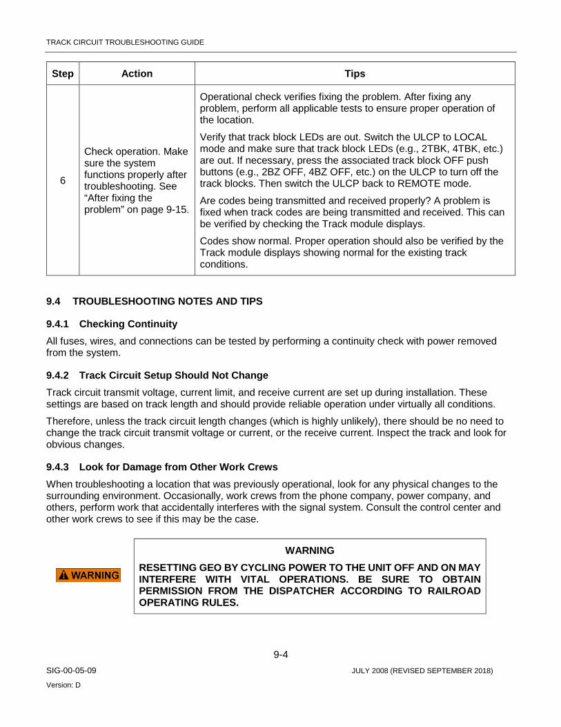
TRACK CIRCUIT TROUBLESHOOTING GUIDE
9-4 SIG-00-05-09 JULY 2008 (REVISED SEPTEMBER 2018)
Version: D
Step Action Tips
6
Check operation. Make sure the system functions properly after troubleshooting. See “After fixing the problem” on page 9-15.
Operational check verifies fixing the problem. After fixing any problem, perform all applicable tests to ensure proper operation of the location.
Verify that track block LEDs are out. Switch the ULCP to LOCAL mode and make sure that track block LEDs (e.g., 2TBK, 4TBK, etc.) are out. If necessary, press the associated track block OFF push buttons (e.g., 2BZ OFF, 4BZ OFF, etc.) on the ULCP to turn off the track blocks. Then switch the ULCP back to REMOTE mode.
Are codes being transmitted and received properly? A problem is fixed when track codes are being transmitted and received. This can be verified by checking the Track module displays.
Codes show normal. Proper operation should also be verified by the Track module displays showing normal for the existing track conditions.
9.4 TROUBLESHOOTING NOTES AND TIPS
9.4.1 Checking Continuity All fuses, wires, and connections can be tested by performing a continuity check with power removed from the system.
9.4.2 Track Circuit Setup Should Not Change Track circuit transmit voltage, current limit, and receive current are set up during installation. These settings are based on track length and should provide reliable operation under virtually all conditions.
Therefore, unless the track circuit length changes (which is highly unlikely), there should be no need to change the track circuit transmit voltage or current, or the receive current. Inspect the track and look for obvious changes.
9.4.3 Look for Damage from Other Work Crews When troubleshooting a location that was previously operational, look for any physical changes to the surrounding environment. Occasionally, work crews from the phone company, power company, and others, perform work that accidentally interferes with the signal system. Consult the control center and other work crews to see if this may be the case.
WARNING RESETTING GEO BY CYCLING POWER TO THE UNIT OFF AND ON MAY INTERFERE WITH VITAL OPERATIONS. BE SURE TO OBTAIN PERMISSION FROM THE DISPATCHER ACCORDING TO RAILROAD OPERATING RULES.
TRACK CIRCUIT TROUBLESHOOTING GUIDE
9-5 SIG-00-05-09 JULY 2008 (REVISED SEPTEMBER 2018)
Version: D
9.4.4 If Communications Problems Occur Communication equipment problems can sometimes be cleared by cycling power to the equipment. Cycle power off and on to the communications equipment as well as to the GEO unit.
The GEO should also be reset by removing and then reapplying power to the unit after replacing any communications equipment.
9.4.5 Troubleshoot by Swapping Modules After eliminating external devices and track circuits, and isolating the problem to the GEO unit, the most effective method of resolving the problem is by exchanging modules that are suspected as defective with known good ones.
GEO modules can be “hot-swapped” by removing them from a GEO chassis and replacing them without removing power from the GEO.
NOTE Each GEO module logs events in memory on that module. Important events are also recorded in memory on the CPU module. Use GEO DT (see Chapter 10 in this manual) to access these logs. Non-volatile read-only memories support these event memories on the CPU modules, but not on other modules. So, when power is removed from a non-CPU module, detailed event history is lost.
9.4.6 Configuring Track Modules Before Swapping When a track module is swapped out of a GEO, be sure to set the jumper for track receive current on the replacement module the same as on the removed module. Refer to How to Set Track Module Receive Current in chapter 7.
Other GEO modules may be hot-swapped without reconfiguration. The new module takes on all the operating parameters of the module it replaces.
9.4.7 Module Swapping Procedure Some problems may require exchanging several modules before restoring the system to full operation. This can result in returning modules that contain no faults.
To avoid returning good modules, we suggest the following procedure to isolate defective modules.
NOTE Following CPU module installation, 2 to 3 minutes are required for the module to perform a system initialization. Following installation of other modules, approximately 45 seconds are required for the module to perform a self-test and report its status to the host CPU module.
TRACK CIRCUIT TROUBLESHOOTING GUIDE
9-6 SIG-00-05-09 JULY 2008 (REVISED SEPTEMBER 2018)
Version: D
NOTE Hot-swapping GEO modules may cause error indications to be set at the ULCP. For example, swapping CLS modules may result in FEK LEDs on the ULCP lighting up. Clear this with the ULCP FE Reset push button.
1. Replace suspected modules one at a time with known good ones until the problem is fixed. Don’t remove modules that have already been replaced until the problem is completely eliminated.
2. Log and tag all modules as they are removed to be sure that good modules are not mixed with bad modules.
3. When the problem is fixed, put back previous modules one at a time, each time checking to see if the problem returns.
4. When a defective module has been isolated, replace only that module with a known good one to verify the module is defective.
5. Return defective modules for repair.
9.5 FAILURE SYMPTOMS
9.5.1 Alarm Messages The CPU module display normally shows the name of the MCF scrolling from right to left. Error messages may be displayed along with the MCF name. Refer to Chapter 7, Setup and Configuration, for details on error messages.
Other equipment connected over the Echelon LAN to GEO can show alarms. Depending on site-specific software, the SEAR II may show an alarm message on its display. SEAR II and ULCP units may also indicate alarms with LEDs.
NOTE The 16 user programmable LEDs on the CPU module front panels have no function on GEO units.
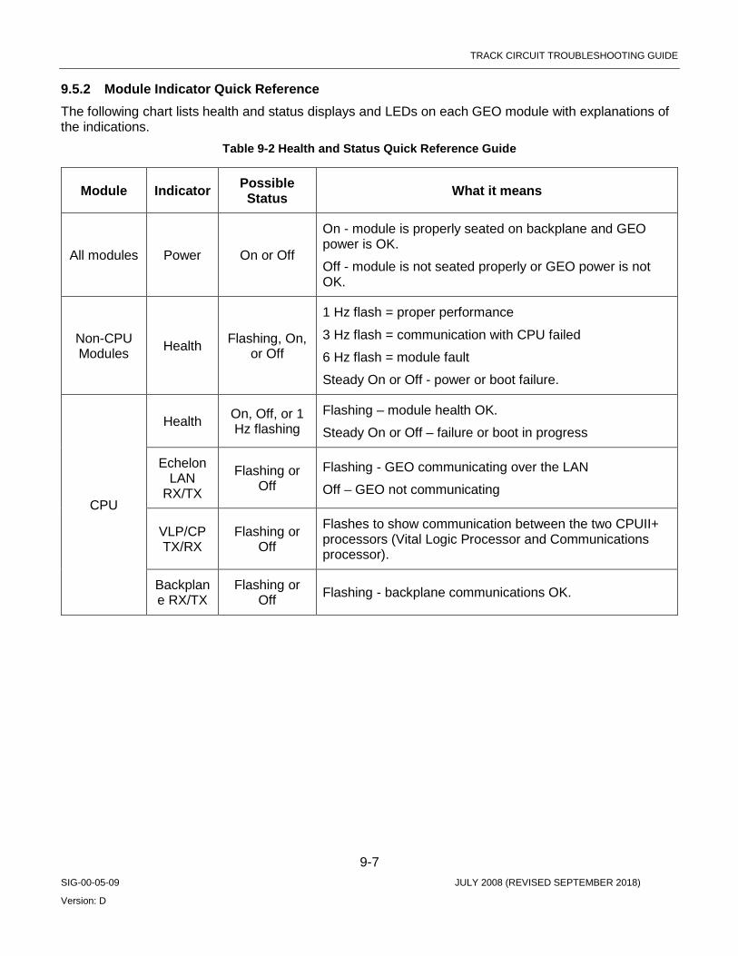
TRACK CIRCUIT TROUBLESHOOTING GUIDE
9-7 SIG-00-05-09 JULY 2008 (REVISED SEPTEMBER 2018)
Version: D
9.5.2 Module Indicator Quick Reference The following chart lists health and status displays and LEDs on each GEO module with explanations of the indications.
Table 9-2 Health and Status Quick Reference Guide
Module Indicator Possible Status What it means
All modules Power On or Off
On - module is properly seated on backplane and GEO power is OK.
Off - module is not seated properly or GEO power is not OK.
Non-CPU Modules Health Flashing, On,
or Off
1 Hz flash = proper performance
3 Hz flash = communication with CPU failed
6 Hz flash = module fault
Steady On or Off - power or boot failure.
CPU
Health On, Off, or 1 Hz flashing
Flashing – module health OK.
Steady On or Off – failure or boot in progress
Echelon LAN
RX/TX
Flashing or Off
Flashing - GEO communicating over the LAN
Off – GEO not communicating
VLP/CP TX/RX
Flashing or Off
Flashes to show communication between the two CPUII+ processors (Vital Logic Processor and Communications processor).
Backplane RX/TX
Flashing or Off Flashing - backplane communications OK.

TRACK CIRCUIT TROUBLESHOOTING GUIDE
9-8 SIG-00-05-09 JULY 2008 (REVISED SEPTEMBER 2018)
Version: D
Module Indicator Possible Status What it means
Track Module
Track Code
Display TX and
RX
Track code, blank, or specific
character
d = disabled.
• If TX displays d, module cannot transmit. • If RX displays d, module cannot receive. (Normally
displayed as module is booting.)
E = error condition
• Module is receiving or is attempting to send an illegal combination of track codes.
• Try replacing module. • If E continues to be displayed, check insulated joints at
both ends of affected circuit.
F = failure condition
• If F is on TX display, module could not send code (F should flash and alternate with code it could not send).
• If F is on RX display, module received a code it could not understand.
Try replacing module.
• Check for DC voltage on tracks with nothing connected. • If F continues to be displayed, look at RX and TX current
levels. • Check for a bad connection in the failed track circuit and
replace the original module. • If F appears on both RX and TX displays, replace
module.
Blank =
• RX blank may indicate a bad connection or lack of signal from adjacent location.
• TX blank suggests a problem with the Track module. • RX and TX both steady blank suggests a failure during
boot.
Fail TX/RX LEDs
Off, On or Flashing
• Flashing - indicates a Track condition fault. • On solid - indicates a Track module fault. • Off - OK.
Current TX/RX LEDs
On, Off or Flashing
• Flash rate proportional to TX or RX current. • Long flash period - low TX or RX current. • Short flash period - high TX or RX current. • On solid - either RX or TX current too high. • Off – TX: suggests open track circuit; • X: suggests track circuit shunt condition.

TRACK CIRCUIT TROUBLESHOOTING GUIDE
9-9 SIG-00-05-09 JULY 2008 (REVISED SEPTEMBER 2018)
Version: D
Module Indicator Possible Status What it means
Line Module
TX Display (upper)
RX Display (lower)
Vital code, blank or specific
character
d = disabled
• If upper display = d, module cannot transmit. • If lower display = d, module cannot receive. (Normally
displayed when module is booting.)
E = error condition
• Module is receiving or is attempting to send an illegal combination of codes.
• Try replacing module.
F = failure condition
• If F is on upper display, module could not send code (F should flash and alternate with code it could not send).
• If F is on lower display, module received a code it could not understand.
• Try replacing module. • If F continues to be displayed, check VRX and VTX
voltage levels. • Check for a bad line connection between Line
modules and/or replace the original module. • If F appears on both upper and lower displays,
replace module.
Blank =
• Upper display blank suggests a problem with the Line module.
• Lower display blank may indicate a bad connection or lack of signal from adjacent location.
• Upper and lower displays both steady blank suggests a failure during boot.
Shorted Line
Detect LED
On/Off • On solid - indicates a Line module transmitter fault, or problem with the line wire between modules.
9.5.3 Interpreting Symptoms When symptoms are reported, it may not be immediately obvious how reported symptoms relate to a specific type of trouble.
A signal problem can cause a symptom that looks like a track problem, and vice versa, since they directly relate to each other. By the same reasoning, signal and track problems can cause a symptom that looks like a switch or I/O problem, and vice versa, since they directly relate to each other.
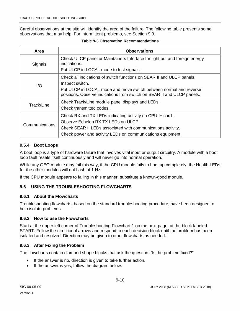
TRACK CIRCUIT TROUBLESHOOTING GUIDE
9-10 SIG-00-05-09 JULY 2008 (REVISED SEPTEMBER 2018)
Version: D
Careful observations at the site will identify the area of the failure. The following table presents some observations that may help. For intermittent problems, see Section 9.9.
Table 9-3 Observation Recommendations
Area Observations
Signals Check ULCP panel or Maintainers Interface for light out and foreign energy indications. Put ULCP in LOCAL mode to test signals.
I/O
Check all indications of switch functions on SEAR II and ULCP panels. Inspect switch. Put ULCP in LOCAL mode and move switch between normal and reverse positions. Observe indications from switch on SEAR II and ULCP panels.
Track/Line Check Track/Line module panel displays and LEDs. Check transmitted codes.
Communications
Check RX and TX LEDs indicating activity on CPUII+ card. Observe Echelon RX TX LEDs on ULCP. Check SEAR II LEDs associated with communications activity. Check power and activity LEDs on communications equipment.
9.5.4 Boot Loops A boot loop is a type of hardware failure that involves vital input or output circuitry. A module with a boot loop fault resets itself continuously and will never go into normal operation.
While any GEO module may fail this way, if the CPU module fails to boot up completely, the Health LEDs for the other modules will not flash at 1 Hz.
If the CPU module appears to failing in this manner, substitute a known-good module.
9.6 USING THE TROUBLESHOOTING FLOWCHARTS
9.6.1 About the Flowcharts Troubleshooting flowcharts, based on the standard troubleshooting procedure, have been designed to help isolate problems.
9.6.2 How to use the Flowcharts Start at the upper left corner of Troubleshooting Flowchart 1 on the next page, at the block labeled START. Follow the directional arrows and respond to each decision block until the problem has been isolated and resolved. Direction may be given to other flowcharts as needed.
9.6.3 After Fixing the Problem The flowcharts contain diamond shape blocks that ask the question, “Is the problem fixed?”
• If the answer is no, direction is given to take further action. • If the answer is yes, follow the diagram below.

TRACK CIRCUIT TROUBLESHOOTING GUIDE
9-11 SIG-00-05-09 JULY 2008 (REVISED SEPTEMBER 2018)
Version: D
First, decide if the problem has been fixed using the guidelines in the following diagram. Then perform all applicable tests to ensure that the system is operating properly. If modules were replaced, retest the system according to railroad approved field test procedures. Only after the system has passed these tests is troubleshooting complete.
Figure 9-1 Fix Confirmation Flow

TRACK CIRCUIT TROUBLESHOOTING GUIDE
9-12 SIG-00-05-09 JULY 2008 (REVISED SEPTEMBER 2018)
Version: D
Figure 9-2 Further Troubleshooting

TRACK CIRCUIT TROUBLESHOOTING GUIDE
9-13 SIG-00-05-09 JULY 2008 (REVISED SEPTEMBER 2018)
Version: D
9.6.4 Help in Identifying a Path Use this chart if you are not sure which troubleshooting path to follow. Look for the indication or symptom in the left column that is closest to the symptom observed. Follow the path indicated in the column on the right.
Possible Symptoms Troubleshooting Path
Vital Control: • The location has failed safe into a restrictive mode. • The CPU module Health LED flashes faster than 1 Hz. • Some or all modules show Health LED flashing faster than 1 Hz.
CPU – path A
Signal: • Signal-stop (Red-Retaining) relay is deactivated. • Light out indication. • Downgraded signal aspect reported.
CLS/SLS – path B
Input/Output: • I/O module Health LED flashes faster than 1 Hz. • Indications from field equipment indicate loss of control. • I/O module continuously reboots.
I/O – path C
Track/Line: • Track/Line module indicates code that is not consistent with normal
conditions at this location. • Track/Line module RX or TX displays d, E, F, or is blank (see charts on
pages 9-13 and 9-14). • Track/Line module Health LED flashes faster than 1 Hz. • (see chart on page 9-12). • Track module: TX or RX Fail LED is on solid or flashing. • Track module: TX or RX Current LED is on solid or completely off (not
flashing). • Line module: Shorted Line Detect LED is on solid. • Track/Line module continuously reboots.
TRK/LIN – path D
Communications: • CPU module communications TX/RX LEDs are not flashing. • ULCP is dark. • GEO Health LED on ULCP is flashing. • Failed or intermittent communications outside of the bungalow (such as
with the dispatch office).
Communications – path E
Red-Retaining Relay Function • Cycling of Red-Retaining relay. • CLS module Health LED(s) flashing at 6 Hz rate. • All block signals controlled by this GEO set to RED. • LOK indications at central office. • CLS converter status “FAILED” messages in CPU status log.
Red-Retaining Relay Function – path G
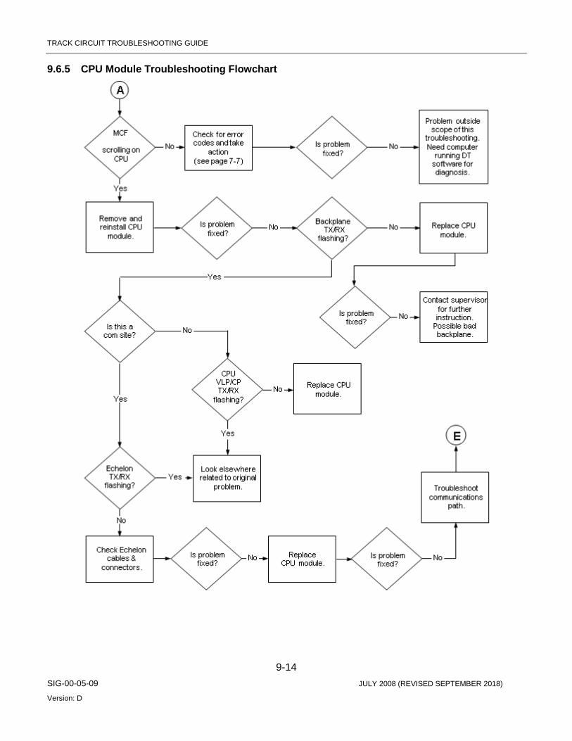
TRACK CIRCUIT TROUBLESHOOTING GUIDE
9-14 SIG-00-05-09 JULY 2008 (REVISED SEPTEMBER 2018)
Version: D
9.6.5 CPU Module Troubleshooting Flowchart
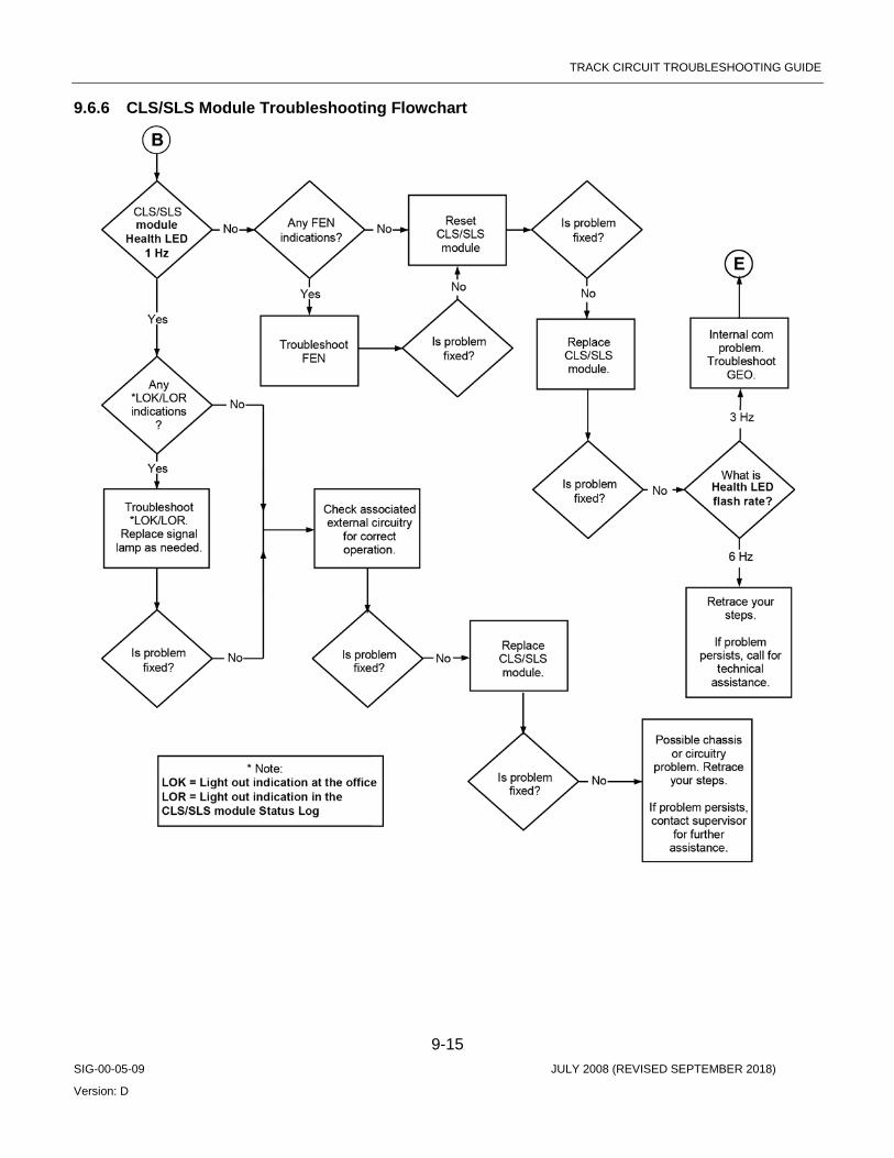
TRACK CIRCUIT TROUBLESHOOTING GUIDE
9-15 SIG-00-05-09 JULY 2008 (REVISED SEPTEMBER 2018)
Version: D
9.6.6 CLS/SLS Module Troubleshooting Flowchart

TRACK CIRCUIT TROUBLESHOOTING GUIDE
9-16 SIG-00-05-09 JULY 2008 (REVISED SEPTEMBER 2018)
Version: D
9.6.7 I/O Module Troubleshooting Flowchart

TRACK CIRCUIT TROUBLESHOOTING GUIDE
9-17 SIG-00-05-09 JULY 2008 (REVISED SEPTEMBER 2018)
Version: D
9.6.8 Track/Line Module Troubleshooting Flowchart
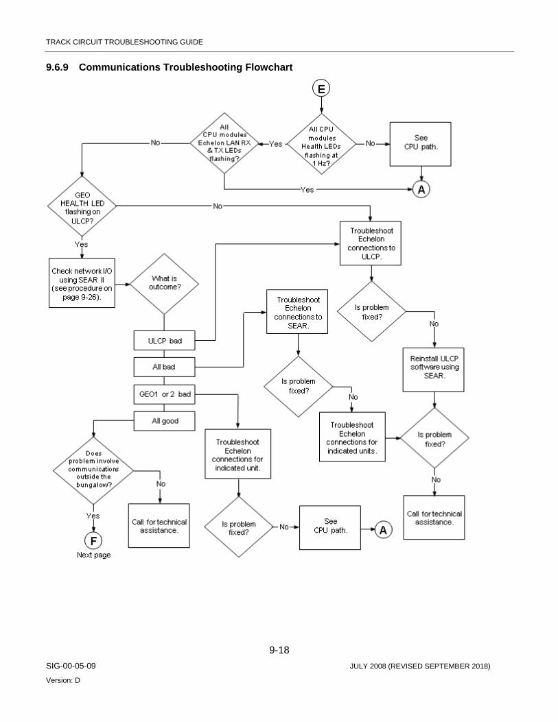
TRACK CIRCUIT TROUBLESHOOTING GUIDE
9-18 SIG-00-05-09 JULY 2008 (REVISED SEPTEMBER 2018)
Version: D
9.6.9 Communications Troubleshooting Flowchart

TRACK CIRCUIT TROUBLESHOOTING GUIDE
9-19 SIG-00-05-09 JULY 2008 (REVISED SEPTEMBER 2018)
Version: D

TRACK CIRCUIT TROUBLESHOOTING GUIDE
9-20 SIG-00-05-09 JULY 2008 (REVISED SEPTEMBER 2018)
Version: D
9.6.10 Red Retaining Relay Function Troubleshooting Flowchart
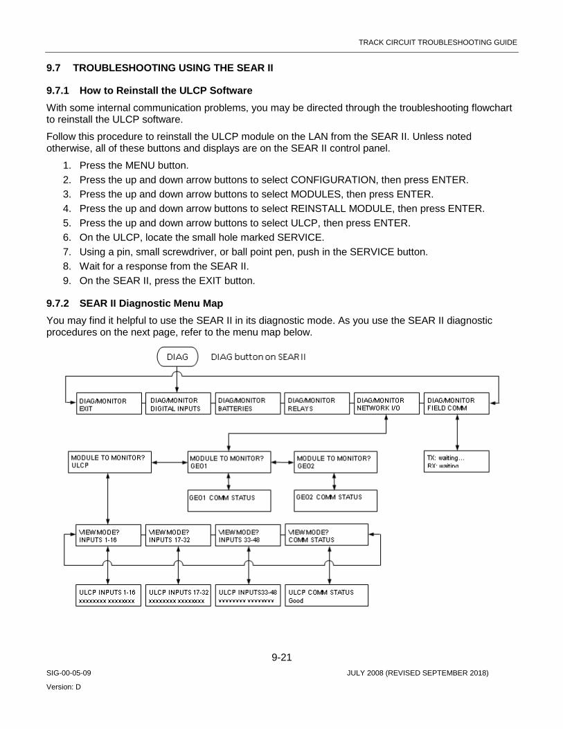
TRACK CIRCUIT TROUBLESHOOTING GUIDE
9-21 SIG-00-05-09 JULY 2008 (REVISED SEPTEMBER 2018)
Version: D
9.7 TROUBLESHOOTING USING THE SEAR II
9.7.1 How to Reinstall the ULCP Software With some internal communication problems, you may be directed through the troubleshooting flowchart to reinstall the ULCP software.
Follow this procedure to reinstall the ULCP module on the LAN from the SEAR II. Unless noted otherwise, all of these buttons and displays are on the SEAR II control panel.
1. Press the MENU button. 2. Press the up and down arrow buttons to select CONFIGURATION, then press ENTER. 3. Press the up and down arrow buttons to select MODULES, then press ENTER. 4. Press the up and down arrow buttons to select REINSTALL MODULE, then press ENTER. 5. Press the up and down arrow buttons to select ULCP, then press ENTER. 6. On the ULCP, locate the small hole marked SERVICE. 7. Using a pin, small screwdriver, or ball point pen, push in the SERVICE button. 8. Wait for a response from the SEAR II. 9. On the SEAR II, press the EXIT button.
9.7.2 SEAR II Diagnostic Menu Map You may find it helpful to use the SEAR II in its diagnostic mode. As you use the SEAR II diagnostic procedures on the next page, refer to the menu map below.
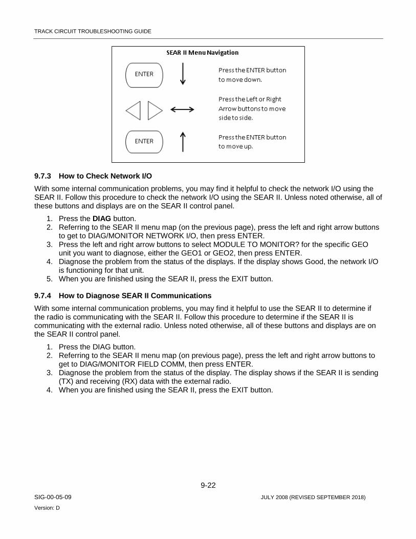
TRACK CIRCUIT TROUBLESHOOTING GUIDE
9-22 SIG-00-05-09 JULY 2008 (REVISED SEPTEMBER 2018)
Version: D
9.7.3 How to Check Network I/O With some internal communication problems, you may find it helpful to check the network I/O using the SEAR II. Follow this procedure to check the network I/O using the SEAR II. Unless noted otherwise, all of these buttons and displays are on the SEAR II control panel.
1. Press the DIAG button. 2. Referring to the SEAR II menu map (on the previous page), press the left and right arrow buttons
to get to DIAG/MONITOR NETWORK I/O, then press ENTER. 3. Press the left and right arrow buttons to select MODULE TO MONITOR? for the specific GEO
unit you want to diagnose, either the GEO1 or GEO2, then press ENTER. 4. Diagnose the problem from the status of the displays. If the display shows Good, the network I/O
is functioning for that unit. 5. When you are finished using the SEAR II, press the EXIT button.
9.7.4 How to Diagnose SEAR II Communications With some internal communication problems, you may find it helpful to use the SEAR II to determine if the radio is communicating with the SEAR II. Follow this procedure to determine if the SEAR II is communicating with the external radio. Unless noted otherwise, all of these buttons and displays are on the SEAR II control panel.
1. Press the DIAG button. 2. Referring to the SEAR II menu map (on previous page), press the left and right arrow buttons to
get to DIAG/MONITOR FIELD COMM, then press ENTER. 3. Diagnose the problem from the status of the display. The display shows if the SEAR II is sending
(TX) and receiving (RX) data with the external radio. 4. When you are finished using the SEAR II, press the EXIT button.

TRACK CIRCUIT TROUBLESHOOTING GUIDE
9-23 SIG-00-05-09 JULY 2008 (REVISED SEPTEMBER 2018)
Version: D
9.8 TROUBLESHOOTING INTERMITTENT PROBLEMS
9.8.1 Types of Failures and Event Log Entries Intermittent failures are typically one of two types:
• Failure of a critical software or hardware circuit or signal path. • Non-critical module failure or an intermittent input from an external source.
An I/O module undergoing the first type of failure will reboot and communications with the CPU module will be interrupted. A CPU module undergoing this type of failure will also reboot. In both cases events will be logged on the CPU and on the module undergoing the failure.
Modules undergoing the second type of failure do not cause the module to reboot but they do result in event log entries.
9.8.2 Accessing Event Logs To access event logs on CPU II+, use a laptop/personal computer loaded with the Siemens Diagnostic Terminal (DT) software. To access event logs on the CPU III, use a laptop with access to WebUI. Select Reports & Logs then Event Log from the left side menu.
By reviewing the event logs, it can be determined if an intermittent failure is being recorded for a module or external device.
9.9 TROUBLESHOOTING WITH A LAPTOP COMPUTER This chapter contains information supporting the use of GEO Diagnostic Terminal (DT) software or WebUI (CPU III) to troubleshoot GEO installations. It includes:
• Introduction • Installing GEO DT on a PC • Connecting a PC with GEO DT to a GEO Unit • Connecting a PC with WebUI to a GEO Unit • Checking GEO status with GEO DT and WebUI • Adjusting Voltages and Currents with GEO DT or WebUI
WARNING THE GEO SYSTEM IS PART OF THE RAILROAD SIGNAL SYSTEM. PERFORMING ANY MAINTENANCE OR ADJUSTMENT PROCEDURE ON THE GEO UNIT COULD AFFECT THE SIGNAL SYSTEM. THEREFORE, ALL SAFETY AND OPERATING RULES OF THE RAILROAD PERTAINING TO THE ADJUSTMENT OR MAINTENANCE OF THE SIGNAL SYSTEM MUST BE COMPLIED WITH.
NOTE For further information on GEO DT, refer to GEO Diagnostic Terminal (DT) Field Handbook (Siemens document number SIG-00-04-17).

TRACK CIRCUIT TROUBLESHOOTING GUIDE
9-24 SIG-00-05-09 JULY 2008 (REVISED SEPTEMBER 2018)
Version: D
NOTE For further information on WebUI, refer to CPU III for GEO and WayConneX (Siemens document number SIG-00-15-04).
9.9.1 Installing GEO DT
9.9.2 System Requirements GEO DT requires the following hardware and software:
• 800 MHz Pentium® class processor at the minimum • 256 MB RAM • CD drive • Microsoft® Windows 98SE®, 2000, XP, or NT 4.0® Operating System with latest Service Pack • Microsoft® Explorer 5.5 or later
9.9.3 Procedure To install GEO Diagnostic Terminal software on a PC:
1. Insert the Diagnostic Terminal software CD in the CD ROM drive. 2. Select the CD drive and run the DT Setup.exe program. 3. When the Diagnostic Terminal setup wizard appears, follow the instructions. 4. Check for any Release Notes before clicking on Finish.
9.10 HOW TO CONNECT DT TO A GEO Connecting DT on a PC to a GEO unit involves:
• Starting the DT software • Configuring a COM port on the PC • Connecting the PC COM port to the GEO • Starting a DT session
9.10.1 Procedure 1. To bring up the DT software and connect DT with a GEO unit:
a. Click on the Siemens icon displayed on the desktop display: b. Or, click on Start, select Programs, then Siemens, then DT.
2. Configure DT for a COM port on the PC by clicking on Comm and then select DT Port Setup. Click to select a COM port and maximum baud rate.
NOTE All GEO modules support up to 56000 baud communication.
3. Connect a serial data cable (RS-232) from the selected COM port to the DIAG connector on the GEO unit CPU module.
4. Once the PC is connected and GEO has booted up, start a DT session by clicking on Comm and the selecting Connect.

TRACK CIRCUIT TROUBLESHOOTING GUIDE
9-25 SIG-00-05-09 JULY 2008 (REVISED SEPTEMBER 2018)
Version: D
5. As DT connects, the status bar indicates progress.
9.10.2 Accessing Siemens WebUI The CPU III module provide a Web Interface which enables the user to configure the GEO locally as well as remotely through the Laptop/Ethernet port on the front of the CPU III module. The Laptop Port default protocol is set as DHCP Server. Connect a laptop computer vie an Ethernet cable to the Laptop port on the front of the CPU III. The CPU III will display an IP address scrolling across the four-character display. This can be accessed by using the Select button to move between the scrolling displayed text. The WebUI uses the HTTP Secure (https) protocol. The CPU III DHCP Server protocol will assign the laptop an IP address once the user has connected with the Ethernet cable this will allow the user to connect to the GEO. The WebUI supports the following web browsers:
• IE 10 and 11 • Firefox (version 46.x) • Chrome (version 55.x)
Open a web browser and type in the IP address of the CPU III. The browser may give the following screens regarding the connection.

TRACK CIRCUIT TROUBLESHOOTING GUIDE
9-26 SIG-00-05-09 JULY 2008 (REVISED SEPTEMBER 2018)
Version: D
Figure 9-3 Unsecure Connection Warning
Click the Advanced option and select the option to proceed to the WebUI.
The WebUI will then appear. Select the user name as Admin (default). There is no Maintainer login option for GEO WebUI.
The default password is Siemens (case sensitive) to open the session. If a specific Admin password has been set, enter this.
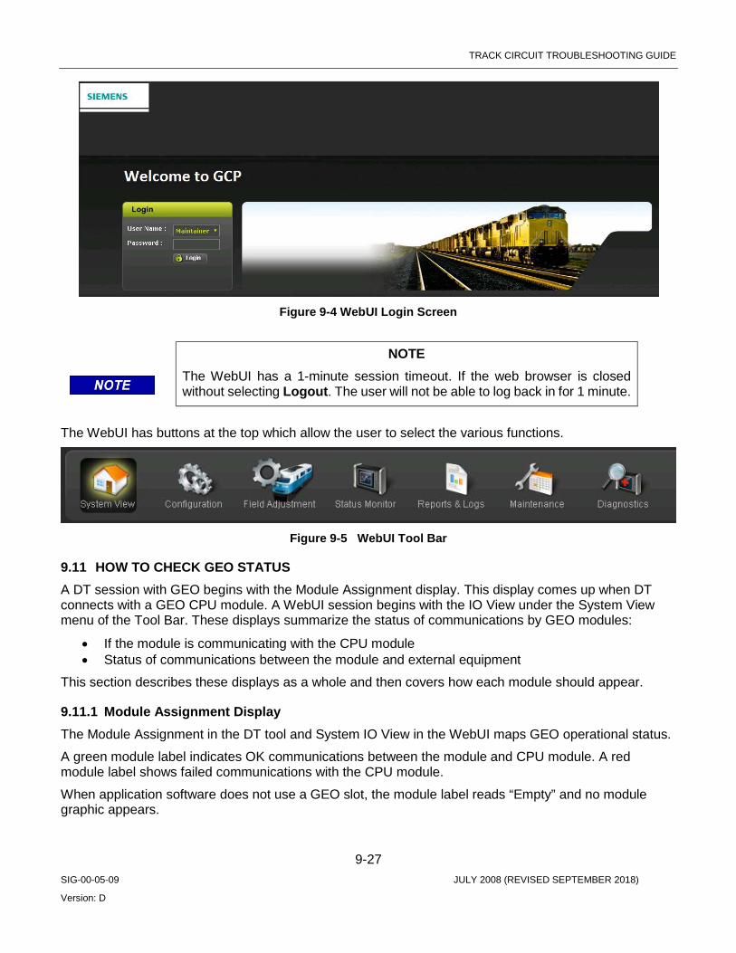
TRACK CIRCUIT TROUBLESHOOTING GUIDE
9-27 SIG-00-05-09 JULY 2008 (REVISED SEPTEMBER 2018)
Version: D
Figure 9-4 WebUI Login Screen
NOTE The WebUI has a 1-minute session timeout. If the web browser is closed without selecting Logout. The user will not be able to log back in for 1 minute.
The WebUI has buttons at the top which allow the user to select the various functions.
Figure 9-5 WebUI Tool Bar
9.11 HOW TO CHECK GEO STATUS A DT session with GEO begins with the Module Assignment display. This display comes up when DT connects with a GEO CPU module. A WebUI session begins with the IO View under the System View menu of the Tool Bar. These displays summarize the status of communications by GEO modules:
• If the module is communicating with the CPU module • Status of communications between the module and external equipment
This section describes these displays as a whole and then covers how each module should appear.
9.11.1 Module Assignment Display The Module Assignment in the DT tool and System IO View in the WebUI maps GEO operational status.
A green module label indicates OK communications between the module and CPU module. A red module label shows failed communications with the CPU module.
When application software does not use a GEO slot, the module label reads “Empty” and no module graphic appears.
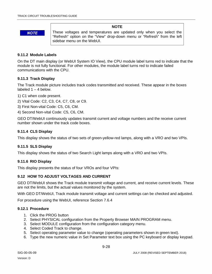
TRACK CIRCUIT TROUBLESHOOTING GUIDE
9-28 SIG-00-05-09 JULY 2008 (REVISED SEPTEMBER 2018)
Version: D
NOTE These voltages and temperatures are updated only when you select the “Refresh” option on the “View” drop-down menu or “Refresh” from the left sidebar menu on the WebUI.
9.11.2 Module Labels On the DT main display (or WebUI System IO View), the CPU module label turns red to indicate that the module is not fully functional. For other modules, the module label turns red to indicate failed communications with the CPU.
9.11.3 Track Display The Track module picture includes track codes transmitted and received. These appear in the boxes labeled 1 – 4 below.
1) C1 when code present. 2) Vital Code: C2, C3, C4, C7, C8, or C9. 3) First Non-vital Code: C5, C6, CM. 4) Second Non-vital Code: C5, C6, CM.
GEO DT/WebUI continuously updates transmit current and voltage numbers and the receive current number shown under the track code boxes.
9.11.4 CLS Display This display shows the status of two sets of green-yellow-red lamps, along with a VRO and two VPIs.
9.11.5 SLS Display This display shows the status of two Search Light lamps along with a VRO and two VPIs.
9.11.6 RIO Display This display presents the status of four VROs and four VPIs:
9.12 HOW TO ADJUST VOLTAGES AND CURRENT GEO DT/WebUI shows the Track module transmit voltage and current, and receive current levels. These are not the limits, but the actual values monitored by the system.
With GEO DT/WebUI, Track module transmit voltage and current settings can be checked and adjusted.
For procedure using the WebUI, reference Section 7.6.4
9.12.1 Procedure 1. Click the PROG button 2. Select PHYSICAL configuration from the Property Browser MAIN PROGRAM menu. 3. Select MODULE configuration from the configuration category menu. 4. Select Coded Track to change. 5. Select operating parameter value to change (operating parameters shown in green text). 6. Type the new numeric value in Set Parameter text box using the PC keyboard or display keypad.

TRACK CIRCUIT TROUBLESHOOTING GUIDE
9-29 SIG-00-05-09 JULY 2008 (REVISED SEPTEMBER 2018)
Version: D
7. Track module transmit voltage, V(Tx), is adjustable from 0 to 4000 millivolts in 20 millivolt increments. Track module transmit current limit is adjustable from 1000 to 10000 milliamperes in 50 milliampere increments.
8. Click Update to save change. 9. Repeat this process for each parameter to be changed. The operating parameter changes take
effect immediately.
9.13 READING GEO LOGS The purpose of this section is to describe how to read, and what certain items mean in various GEO logs. Following sections detail how to access these logs.
9.13.1 Summary Logs Example: 1E7 11JUL06 07:18:11.8 ATCS Rx session lost 6 1E7 11JUL06 07:22:48.7 ATCS Rx session lost 2 1E7 11JUL06 07:22:48.7 ATCS Rx session lost 3 1E7 11JUL06 07:22:48.7 ATCS Rx session lost 5 1E7 11JUL06 07:28:21.4 Parameter Change Error: Protocol Wrong 1E7 11JUL06 07:29:06.7 Parameter Change Error: Protocol Wrong 0E0 11JUL06 07:31:47.1 Reboot Occurred (RSR 128), CP: 0E7 11JUL06 07:31:47.2 Logical Layout = 1 0E7 11JUL06 07:31:47.2 Physical Layout = 1 1E7 11JUL06 07:32:31.5 Logical Layout = 1 1E7 11JUL06 07:32:31.5 Physical Layout = 1 1E8 11JUL06 07:32:31.6 Startup Check Error: 47, UCN check failed 1E0 11JUL06 07:32:31.6 VLP Unconfigured 0E7 11JUL06 07:32:31.8 Low Battery Threshold: 90 mV 1E7 11JUL06 07:32:43.7 Parameter Change Error: Protocol Wrong 1E7 11JUL06 07:32:50.4 Parameter Change Error: Protocol Wrong 1E0 11JUL06 07:33:08.7 Reboot Occurred (RSR 16 ), VLP2 1E7 11JUL06 07:33:46.5 Logical Layout = 1 1E7 11JUL06 07:33:46.5 Physical Layout = 1 1E0 11JUL06 07:33:47.4 VLP Fully Operational 1E0 11JUL06 07:33:48.6 Rx Session Established VLP with slot 6 1E0 11JUL06 07:33:49.4 Rx Session Established VLP with slot 3 1E0 11JUL06 07:33:49.4 Rx Session Established VLP with slot 4 1E0 11JUL06 07:33:50.3 ATCS Rx Session established 1 1E0 11JUL06 07:33:50.3 ATCS Rx Session established 2 1E0 11JUL06 07:33:50.3 ATCS Rx Session established 3 1E0 11JUL06 07:33:50.3 ATCS Rx Session established 4 1E0 11JUL06 07:33:51.0 ATCS Rx Session established 5 1E0 11JUL06 07:33:51.0 ATCS Rx Session established 6 1E0 11JUL06 07:33:51.7 Rx Session Established VLP with slot 5 1E0 11JUL06 07:33:52.7 Rx Session Established VLP with slot 7
9.13.2 Decoding Summary Logs The above example shows a typical reboot of an appliance model application using a CPU 2 + module. The slot 0 references the CP portion of the CPU module. The events with first number equal to 1 is referred to VLP portion of the CPU module. The RX session messages refer to the physical slots on the chassis. The ATCS RX messages refer to the GEO objects (these are Echelon Communication links and
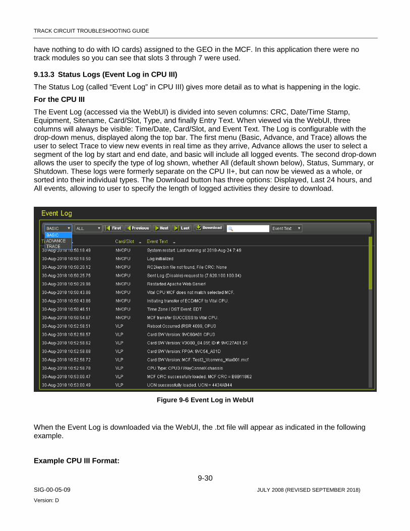
TRACK CIRCUIT TROUBLESHOOTING GUIDE
9-30 SIG-00-05-09 JULY 2008 (REVISED SEPTEMBER 2018)
Version: D
have nothing to do with IO cards) assigned to the GEO in the MCF. In this application there were no track modules so you can see that slots 3 through 7 were used.
9.13.3 Status Logs (Event Log in CPU III) The Status Log (called “Event Log” in CPU III) gives more detail as to what is happening in the logic.
For the CPU III The Event Log (accessed via the WebUI) is divided into seven columns: CRC, Date/Time Stamp, Equipment, Sitename, Card/Slot, Type, and finally Entry Text. When viewed via the WebUI, three columns will always be visible: Time/Date, Card/Slot, and Event Text. The Log is configurable with the drop-down menus, displayed along the top bar. The first menu (Basic, Advance, and Trace) allows the user to select Trace to view new events in real time as they arrive, Advance allows the user to select a segment of the log by start and end date, and basic will include all logged events. The second drop-down allows the user to specify the type of log shown, whether All (default shown below), Status, Summary, or Shutdown. These logs were formerly separate on the CPU II+, but can now be viewed as a whole, or sorted into their individual types. The Download button has three options: Displayed, Last 24 hours, and All events, allowing to user to specify the length of logged activities they desire to download.
Figure 9-6 Event Log in WebUI
When the Event Log is downloaded via the WebUI, the .txt file will appear as indicated in the following example.
Example CPU III Format:

TRACK CIRCUIT TROUBLESHOOTING GUIDE
9-31 SIG-00-05-09 JULY 2008 (REVISED SEPTEMBER 2018)
Version: D
CRC Date/Time Equipment Sitename Card/Slot Type Entry Text
==== ======================= ========= ========= ========= ===== ==================
E144 25-Sep-2018 09:14:00.54 VLP Brighton VLP STAT CSX2WT: CODE TX 1 2
BD70 25-Sep-2018 09:14:00.56 VLP Brighton VLP STAT 8E: BaLG Undef
260C 25-Sep-2018 09:14:00.69 VLP Brighton VLP STAT 6CT: LeLG Stale
A3C2 25-Sep-2018 09:14:00.75 VLP Brighton VLP STAT 6E: BaLG Stale
7E2F 25-Sep-2018 09:14:00.77 VLP Brighton VLP STAT 6CT: LeLG Undef
9F20 25-Sep-2018 09:14:00.83 VLP Brighton VLP STAT CSX1WT: CODE TX 1 2
1CE7 25-Sep-2018 09:14:00.87 VLP Brighton VLP STAT 6E: BaLG Undef
ABE4 25-Sep-2018 09:14:01.50 VLP Brighton VLP STAT 8E: BlockedDelay start:0h0 m 0. 0 s
115C 25-Sep-2018 09:14:01.52 VLP Brighton VLP STAT 8E: BlockedDelay stop: 0h0 m 0. 0 s
8CF9 25-Sep-2018 09:14:01.60 VLP Brighton VLP STAT 8E: SigClr Idle
377E 25-Sep-2018 09:14:01.62 VLP Brighton VLP STAT 6CT:LePG Stale
6271 25-Sep-2018 09:14:01.66 VLP Brighton VLP STAT 6E: BlockedDelay start:0h0 m 0. 0 s
098E 25-Sep-2018 09:14:01.72 VLP Brighton VLP STAT 6E: BlockedDelay stop: 0h0 m 0. 0 s
77D2 25-Sep-2018 09:14:01.78 VLP Brighton VLP STAT 6E: SigClr Idle
0CF8 25-Sep-2018 09:14:01.84 VLP Brighton VLP STAT 6CT:LePG Undef
C0E0 25-Sep-2018 13:37:26.16 VLP Brighton NVCPU UI M (WebUser): Log in
For the CPU II+ The first portion is the same as all the other logs with the slot and the Date/Time stamp. The “9W9T:” is the GEO object name as defined in the logic. The “fa” is the facing side of the switch. The “no and re” are normal and reverse respectively. The out and in comments indicate what GEO messages are being sent or received to that object. These logs are commented next to the line for clarity and represent a Switch request from normal to reverse.
Example CPU II+ Format: 0E2 11JUL06 20:48:11.7 9W9T: NZ False
NZ False is the loss of that control from the SEAR 0E2 11JUL06 20:48:11.7 9W9T: RZ True
RZ True is the control from the SEAR getting to GEO 0E2 11JUL06 20:48:11.7 9W9T: SwReq Rev
The SwReq is Switch request and REV means reverse. 0E2 11JUL06 20:48:11.7 9W9T: SwMove Moving
This line tells us that we need to move the switch. 0E2 11JUL06 20:48:11.7 9W9T: NWR Deenergized
This is making sure the NWR output is off.

TRACK CIRCUIT TROUBLESHOOTING GUIDE
9-32 SIG-00-05-09 JULY 2008 (REVISED SEPTEMBER 2018)
Version: D
0E2 11JUL06 20:48:11.7 9W9T: RWR Energized
This is making sure the RWR output is on. 0E2 11JUL06 20:48:11.7 9W9T: fa out ST True
This line and the next six lines are GEO messages being sent to other objects. 0E2 11JUL06 20:48:11.7 9W9T: fa out RC False
0E2 11JUL06 20:48:11.7 9W9T: fa out aspect Value Not Found
0E2 11JUL06 20:48:11.7 9W9T: fa out rsig 65535
0E2 11JUL06 20:48:11.7 9W9T: fa out HR False
0E2 11JUL06 20:48:11.7 9W9T: no out RC False
0E2 11JUL06 20:48:11.7 9W9T: no out HR False
0E2 11JUL06 20:48:11.7 9W9T: NK False
This is an indication going to the SEAR showing the switch is not normal. 0E2 11JUL06 20:48:11.7 9W9T: NK2 False
This is another indication going to the SEAR showing switch is not normal. 0E2 11JUL06 20:48:11.7 9W9T: NZK2 False
This is an indication sent to the SEAR matching the indications with the controls. 0E2 11JUL06 20:48:11.7 9W9T: RZK2 True
This is an indication to the SEAR showing that the reverse request is in the GEO. 0E0 11JUL06 20:48:12.0 9W9T: OLTime start: 0 h 0 m 15. 0 s
This is the start of the switch overload timer. 0E2 11JUL06 20:48:14.5 9W9T: RZ False
This is the reverse control from the SEAR going low. 0E2 11JUL06 20:48:14.8 9W9T: no in RTTM False
More GEO messages 0E2 11JUL06 20:48:14.8 9W9T: fa out RTTM False
0E2 11JUL06 20:48:15.7 9W9T: NWP Deenergized
The Switch has moved far enough to lose the input to GEO. 0E2 11JUL06 20:48:16.0 9W9T: RWP Energized
The switch reverse input to GEO is now true. 0E2 11JUL06 20:48:16.0 9W9T: fa in RTTM False
0E2 11JUL06 20:48:16.0 9W9T: SwMove IdleRe
This is a message saying the switch movement should stop. 0E2 11JUL06 20:48:16.0 9W9T: fa out RE False
0E2 11JUL06 20:48:16.0 9W9T: fa out RC True
GEO message telling the other objects the switch is reverse. 0E2 11JUL06 20:48:16.0 9W9T: fa out aspect HDI2N

TRACK CIRCUIT TROUBLESHOOTING GUIDE
9-33 SIG-00-05-09 JULY 2008 (REVISED SEPTEMBER 2018)
Version: D
0E2 11JUL06 20:48:16.0 9W9T: fa out rsig 1
0E2 11JUL06 20:48:16.0 9W9T: no out AE False
0E2 11JUL06 20:48:16.0 9W9T: no out RE False
0E2 11JUL06 20:48:16.0 9W9T: no out SE False
0E2 11JUL06 20:48:16.0 9W9T: no out T1E False
0E2 11JUL06 20:48:16.0 9W9T: no out T2E False
0E2 11JUL06 20:48:16.0 9W9T: no out _T1E False
0E2 11JUL06 20:48:16.0 9W9T: no out RC2 False
0E2 11JUL06 20:48:16.0 9W9T: no out RTTM False
0E2 11JUL06 20:48:16.0 9W9T: RK True
This is an indication to the SEAR showing the switch is reverse. 0E2 11JUL06 20:48:16.0 9W9T: RK2 True
This is an indication to the SEAR showing the switch is reverse. 0E2 11JUL06 20:48:26.0 9W9T: RWR Deenergized
This shows the output for the switch control relay is off 0E0 11JUL06 20:48:27.1 9W9T: OLTime expired
This shows the overload timer has expired.
The next set of logs represents some track code changes and signal changes. The information in them will be commented sparingly. The 2ZT is the exit track. The 6 sig is the signal being requested.
Example: 0E2 24OCT06 07:44:26.9 2ZT CODE TX 1 6
The signal is requested and the block is tumbled. 0E2 24OCT06 07:44:28.3 6 sig R/G/R
This tells the signal it should go R/G/R 0E2 24OCT06 07:44:28.3 6 SigClr Locked
0E2 24OCT06 07:44:28.3 6 SigRel Clear
0E2 24OCT06 07:44:28.3 6 HeLG Valid
0E2 24OCT06 07:44:28.3 6 AspectOut MEDIUM CLEAR
This is the defined name for the aspect to be displayed. 0E2 24OCT06 07:44:28.3 6 BG On
The B head green is told to turn on. 0E2 24OCT06 07:44:28.3 6 BR Off
The B head red is told to turn off.

TRACK CIRCUIT TROUBLESHOOTING GUIDE
9-34 SIG-00-05-09 JULY 2008 (REVISED SEPTEMBER 2018)
Version: D
0E2 24OCT06 07:44:28.3 6 GK True
The signal is indicating to the SEAR. 0E2 24OCT06 07:44:28.3 6 ASK False
The ASR is indicating false to the SEAR. 0E2 24OCT06 07:44:29.7 6ZT CODE TX 1 3
Codes to the rear of the 6 signal are changed. 0E2 24OCT06 07:44:31.0 6 BG Status On
The aspect is confirmed as being on. 9E7 24OCT06 07:44:57.6 TRK Avg Current Failure: I1= 0 I2= 0 I3= 0 mA
This represents an open track circuit in slot 9. 0E2 24OCT06 07:44:58.3 6ZT CODE RX 1 3 TXF
The TXF shows the transmit failure because of the open. 0E2 24OCT06 07:45:00.6 6ZT CODE RX No Code TXF
The GEO now responds to the open circuit with no code in. 0E2 24OCT06 07:45:00.6 6ZT CodeM NoCode
0E2 24OCT06 07:45:00.6 6ZT CODE TX 1 2
This is the code into shunt. 0E2 24OCT06 07:45:00.6 6ZT TK True
This sends the track indication to the SEAR. 0E2 24OCT06 07:45:00.6 TRSW: Tumbledown Hold
0E2 24OCT06 07:45:01.3 6 RTT Approach
0E2 24OCT06 07:45:02.8 6 HePG Valid
0E2 24OCT06 07:45:08.5 1 TR Deenergized
This is the OS track input going low. 0E2 24OCT06 07:45:08.5 1 LOS Occupied
This shows the logic sees the OS occupied. 0E2 24OCT06 07:45:08.5 1 OccDir Trailing
This shows what direction the OS was occupied from. 0E2 24OCT06 07:45:09.2 2 SigReq OS
0E2 24OCT06 07:45:09.2 6 sig R/R/R
This shows the signal should now go to stop.
9.13.4 Verbosity Levels The verbosity is the level of detail that is recorded in the logs. The higher the verbosity the quicker the memory will fill up. Under normal operation the verbosity levels for the CP and each module should be set to the minimum setting. This setting will give the field personnel all the information they need to diagnose events that would be associated with train traffic.

TRACK CIRCUIT TROUBLESHOOTING GUIDE
9-35 SIG-00-05-09 JULY 2008 (REVISED SEPTEMBER 2018)
Version: D
The higher settings are used by Siemens personnel to diagnose items ranging from the hardware level to the embedded software level.
To change a module’s verbosity level using the DT, right-click on the module label on the DT screen and select Set Verbosity.
To change the verbosity level using WebUI, access the Configuration menu via the Tool Bar. Under that menu access Non-Vital Configuration > Log Setup > Log Verbosity Settings. Each Module setting will be available from this screen.
Figure 9-7 Change Verbosity Settings
9.13.5 Log Retention The CPU module is the only module that can hold log memory. All other modules will lose the log information when the card loses power. Therefore, if there is a problem and a module is suspected to be the cause, the logs from that module should be recovered before removing the card. These logs should help to prove the module is indeed the problem or provide information to Siemens to determine what the problem is.
9.14 HOW TO VIEW THE STATUS (EVENT) LOG The Status Log includes all event history for a GEO module including:
• System status events • Parameter changes • Internal command activity

TRACK CIRCUIT TROUBLESHOOTING GUIDE
9-36 SIG-00-05-09 JULY 2008 (REVISED SEPTEMBER 2018)
Version: D
• Session status • RX and TX session activity
The Status Log for the VLP includes messages from other modules.
NOTE The status log for the CPU module uses non-volatile memory so this log is not lost when the CPU loses power. On all other cards, the status log is lost when the module loses power.
9.14.1 To Check the Status Log for a Module via DT 1. Right-click on the module label 2. Select Status Log 3. Status Log display: The level of detail in the log entries goes up with the verbosity level from 1 to
5. CPU CP processor is limited to verbosity levels 1 and 2. To change the verbosity level, right-click on the module label and select Set Verbosity.
4. Use the buttons at the top of the error log to navigate: 5. To update the Status Log listing, click on the CARD button and select the same module. 6. To leave the log, click to CLOSE button.
9.14.2 To Check the Status Log for a Module via WebUI 1. Select the Reports & Logs icon from the Tool bar 2. Select VLP/IO Card Log 3. The Status Log display can now be selected for each individual slot.
Figure 9-8 Adjust Verbosity of Status Log
4. The level of detail in the log entries goes up with the verbosity level from 1 to 5. To change the verbosity level, use the drop-down Verbosity menu menu. See Figure 9-7.
5. Use the buttons at the top of the error log (Previous and Next) to navigate.

TRACK CIRCUIT TROUBLESHOOTING GUIDE
9-37 SIG-00-05-09 JULY 2008 (REVISED SEPTEMBER 2018)
Version: D
9.15 HOW TO VIEW THE SUMMARY LOG The Summary Log includes the following major event history:
• Reboots • Critical errors • Parameter changes
The Summary Log for the VLP includes UCN, MCF CRC, and fully operational start events.
NOTE The summary log for the CPU module uses non-volatile memory so this log is not lost when the CPU loses power. On all other cards, the status log is lost when the module loses power.
9.15.1 To Check the Summary Log for a Module Using DT 1. Right-click on the module label. 2. Select Summary Log. 3. Summary Log display. 4. Use the buttons at the top of the error log to navigate. 5. To update the Summary Log listing, click on the CARD button and select the same module. 6. To leave the log, click on the CLOSE button.
9.15.2 To Check the Summary Log for a Module Using WebUI 1. Select the Reports & Logs icon from the Tool bar 2. Select VLP/IO Card Log. From the first drop down menu on the screen, select Summary.
Figure 9-9 Summary View of Log
3. The Summary Log display can now be selected for each individual slot. 4. Use the buttons at the top of the error log (Previous and Next) to navigate.
9.16 HOW TO VIEW THE ATCS COMMUNICATION LINKS The CPU II+ module allows “ATCS Communications” to be used to check the status of communications links between the GEO and other networked devices. To view in DT, click the VIEW button, then and select ATCS Communication Links. The ATCS communication links display.
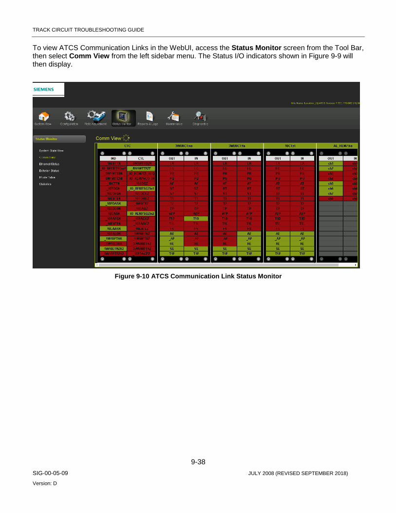
TRACK CIRCUIT TROUBLESHOOTING GUIDE
9-38 SIG-00-05-09 JULY 2008 (REVISED SEPTEMBER 2018)
Version: D
To view ATCS Communication Links in the WebUI, access the Status Monitor screen from the Tool Bar, then select Comm View from the left sidebar menu. The Status I/O indicators shown in Figure 9-9 will then display.
Figure 9-10 ATCS Communication Link Status Monitor
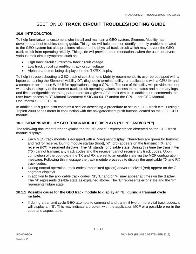
TRACK CIRCUIT TROUBLESHOOTING GUIDE
10-39 SIG-00-05-09 JULY 2008 (REVISED SEPTEMBER 2018)
Version: D
SECTION 10 TRACK CIRCUIT TROUBLESHOOTING GUIDE
10.0 INTRODUCTION To help familiarize its customers who install and maintain a GEO system, Siemens Mobility has developed a brief troubleshooting guide. This guide will help the user identify not only problems related to the GEO system but also problems related to the physical track circuit which may prevent the GEO track circuit from operating reliably. This guide will provide recommendations when the user observers various track circuit symptoms such as:
• High track circuit current/low track circuit voltage • Low track circuit current/high track circuit voltage • Alpha characters being displayed in the TX/RX display
To help in troubleshooting a GEO track circuit Siemens Mobility recommends its user be equipped with a laptop containing the Siemens Mobility DT, diagnostic terminal, utility for applications with a CPU II+ and a computer able to use WebUI for applications using a CPU III. The use of this utility will provide the user with a visual display of the current track circuit operating values, access to the status and summary logs, and field configurable operating parameters for a given GEO track circuit. In addition it recommends the user have access to DT Manual Document # SIG-00-04-17 and/or the CPU III for GEO Manual, Document# SIG-00-15-04.
In addition, this guide also contains a section describing a procedure to setup a GEO track circuit using a Triplett 2000 series meter in conjunction with the navigate/select push buttons located on the GEO CPU module.
10.1 SIEMENS MOBILITY GEO TRACK MODULE DISPLAYS (“D” “E” AND/OR “F”) The following document further explains the “d”, “E” and “F” representation observed on the GEO track module displays.
• Each GEO track module is equipped with a 7-segment display. Characters are green for transmit and red for receive. During module startup (boot), "d" (d/d) appears on the transmit (TX) and receive (RX) 7-segment displays. The "d" stands for disable state. During this time the transmitter (TX) cannot transmit any track codes and the receiver cannot receive any track codes. Upon completion of the boot cycle the TX and RX are set to an enable state via the MCF configuration message. Following this message the track module proceeds to display the applicable TX and RX track codes.
• During normal operation, track codes transmitted (green) and/or received (red) appear on the 7-segment displays.
• In addition to the applicable track codes, “d”, “E” and/or “F” may appear at times on the display. The “d” represents disable state as explained above. The “E” represents error state and the “F” represents failure state.
10.1.1 Possible cause for the GEO track module to display an “E” during a transmit cycle include:
• If during a transmit cycle GEO attempts to command and transmit two or more vital track codes, it will display an “E”. This may indicate a problem with the application MCF or a possible error in the code and aspect table.

TRACK CIRCUIT TROUBLESHOOTING GUIDE
10-40 SIG-00-05-09 JULY 2008 (REVISED SEPTEMBER 2018)
Version: D
10.1.2 Possible cause for the GEO track module to display an “E” during a receive cycle include:
• During a receive cycle GEO may display an “E” if the receiver sensitivity level is set too low. This may indicate a problem with changing ballast conditions for that section of track and/or the GEO track circuit is not properly adjusted. Verify the transmit output voltage level of the applicable track module and/or that the receiver sensitivity level jumpers are properly adjusted.
10.1.3 Possible causes for the GEO track module to display an “F” during transmit cycle include:
• Track output voltage does not meet transmit threshold voltage. This generates a GEO “TRK VCO Voltage Fail” error. This error may be caused by external noise on the track circuit, i.e. AC interference. Verify the condition of the GEO track circuit.
• Requested transmitter voltage does not meet requested transmit threshold voltage. This generates a GEO “TRK DAC Voltage Fail” error. This is an internal module test and if this condition persists, replace and return the module to Siemens Mobility.
• Track output voltage feedback 1 and track output voltage feedback 2 disagree by 25%. This generates a GEO “TRK VCO Voltage Fdbk Fail” error. This error may be caused by noise (AC) and/or surges on the GEO track circuit. Also verify the GEO operating battery to ensure it is at acceptable levels.
• Track output current does not meet track output threshold current. This generates a GEO “TRK Avg Current Failure” error. This error may be caused by an open in the GEO track circuit. Verify the condition of the track leads. High levels of AC interference may also cause this error to be generated.
• Track output current feedback 1 and track output current feedback 2 disagree by 20%. This generates a GEO “TRK VCO Current Fdbk Fail” error. Same as D above. This error may be caused by an open in the GEO track circuit. Verify the condition of the track leads. High levels of AC interference can also cause this error to be generated.
• Track module receiver is detecting a surge. This generates a GEO “TRK RX Surge Limit Failure” error. This error may be caused by a surge and/or an over energized GEO track circuit. Verify the applicable GEO transmitter and receiver are properly adjusted.
10.1.4 Possible causes for the GEO track module to display an “F” during receive cycle include:
• Track receiver is experiencing a surge(s). This generates a GEO “TRK RX Surge Limit Failure” error. Same as F above. This error may be caused by a surge and/or an over energized GEO track circuit. Verify the applicable GEO transmitter and receiver are properly adjusted.
• Hall Effect sensor fails sensitivity test. This generates a GEO “TRK HES Digital Level Failure” error. This error may be caused by an improperly tuned Hall Effect sensor. If this problem persists the module should be replaced and returned to Siemens Mobility.
• Hall Effect sensor circuit fails. This generates a GEO “TRK HES Stability Failure” error. This error may be caused by high levels of AC on the GEO track circuit. With the use of the DT verify the module operating parameters by viewing the status log.
• Track receiver is picking up DC bias. This generates a GEO “TRK DC Bias Failure” error. This error may be caused by another DC source present on the GEO track circuit. Verify the GEO track circuit to ensure there is no other DC source present.

TRACK CIRCUIT TROUBLESHOOTING GUIDE
10-41 SIG-00-05-09 JULY 2008 (REVISED SEPTEMBER 2018)
Version: D
NOTE In general, a possible cause for transmitter errors can be attributed to a low DC battery condition. Verify the B-12 supply to the GEO unit is at an acceptable level, nominal 12.0 vdc on the GEO input terminals.
NOTE When any of the above errors are generated, the applicable transmitter and/or receiver may be disabled. However, the track module transmitter and/or receiver will attempt to recover from any of the above errors every 10 seconds.
10.2 TRACK CIRCUIT TROUBLE SYMPTOMS
10.2.1 Open Track Circuit Possible causes: track circuit adjusted too low, broken rail, open test link or test nut, broken wire, bad bond, blown receive fuse on GEO track module, blown track fuse on GEO chassis.
• Track card RX display is dark • Track card TX display will typically alternate between intended track code and “F”. See section on
the alpha character display.
• “Track code in” LED on track module will remain dark. • “Track code out” LED on track module will continue to flash as code is sent out by the GEO track
module. • The DT (Diagnostic Terminal software) or WebUI display will show “Fail” and the track code that
the GEO is attempting to send. Little or no TX amps will be indicated. (A) • The DT or WebUI display will indicate “NC” for no code received, and no RX amps will be
indicated. (B) • An open track circuit is indicated in the GEO CP status log with a “TRK VCO Current Fdbk Fail”
error.
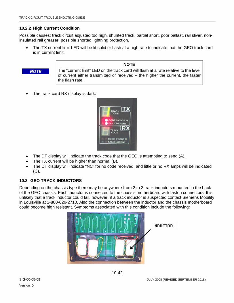
TRACK CIRCUIT TROUBLESHOOTING GUIDE
10-42 SIG-00-05-09 JULY 2008 (REVISED SEPTEMBER 2018)
Version: D
10.2.2 High Current Condition Possible causes: track circuit adjusted too high, shunted track, partial short, poor ballast, rail sliver, non-insulated rail greaser, possible shorted lightning protection.
• The TX current limit LED will be lit solid or flash at a high rate to indicate that the GEO track card is in current limit.
NOTE The “current limit” LED on the track card will flash at a rate relative to the level of current either transmitted or received – the higher the current, the faster the flash rate.
• The track card RX display is dark.
• The DT display will indicate the track code that the GEO is attempting to send (A). • The TX current will be higher than normal (B). • The DT display will indicate “NC” for no code received, and little or no RX amps will be indicated
(C).
10.3 GEO TRACK INDUCTORS Depending on the chassis type there may be anywhere from 2 to 3 track inductors mounted in the back of the GEO chassis. Each inductor is connected to the chassis motherboard with faston connectors. It is unlikely that a track inductor could fail, however, if a track inductor is suspected contact Siemens Mobility in Louisville at 1-800-626-2710. Also the connection between the inductor and the chassis motherboard could become high resistant. Symptoms associated with this condition include the following:

TRACK CIRCUIT TROUBLESHOOTING GUIDE
10-43 SIG-00-05-09 JULY 2008 (REVISED SEPTEMBER 2018)
Version: D
• With the DT (or WebUI) connected, a large swing in the transmit amps will be observed (A). Also, the GEO track circuit may not recover to its previously adjusted value after a train move (B).
• This condition could cause the track circuit to be re-adjusted frequently.
NOTE A VCO setting above 2800 mV indicates a possible track circuit problem and should be investigated.
NOTE The GEO status log (Event Log in CPU III) will typically not record any errors associated with a high resistance track inductor. Large swings in TX current and frequent re-setting of the track circuit are indications of this condition.
10.4 REVERSE POLARITY OF TRACK CIRCUIT WIRING
• TX display on GEO track card will appear as normal. • RX display will remain dark.
• “Track code in” LED on track module will remain dark. • “Track code out” LED on track module will continue to flash as code is sent out by the GEO track
module. • Reverse polarity of track circuit wires will typically be indicated in the GEO CP status log with a
“TRK VCO Current Fdbk Fail” error
10.5 BAD INSULATED JOINT – WITHOUT CODE 5 PRESENT
10.5.1 GEO Coded Track to GEO Coded Track, Non-Staggered Polarity – One Bad Joint
• No noticeable changes to TX or RX displays on GEO track modules. • No noticeable changes on the DT. • Typically, there will be no errors recorded in the GEO logs.
NOTE Typically, one bad insulated joint will not prevent a GEO track circuit from operating safely and reliably.
TRACK CIRCUIT TROUBLESHOOTING GUIDE
10-44 SIG-00-05-09 JULY 2008 (REVISED SEPTEMBER 2018)
Version: D
10.5.2 GEO Coded Track to GEO Coded Track, Non-Staggered Polarity – Two Bad Joints
• Both GEO track cards TX will display vital code as normal. • Both GEO track cards RX will display vital code as normal. • The TX status for both tracks on the DT will display higher than normal amps (A). • The RX status for both tracks will display a lower than normal amps (B). • Typically, there will be no errors recorded in the GEO logs.
NOTE Applying a shunt on one track circuit will cause both track circuits to fail.
10.5.3 GEO Coded Track to DC Track – One Bad Joint
• GEO track card TX will display vital code as normal. • GEO track card RX will display vital code as normal. • No noticeable changes on the DT TX or RX status. • Typically, there will be no errors recorded in the GEO logs.
10.5.4 GEO Coded Track to DC Track – Two Bad Joints
• The TX display on the track module may alternate between a 1 and a vital code. • The RX display on the track module will alternate between “F” and dark. • RX status of the affected track module will alternate between FAIL and NC on the DT (A). • The log for the affected track module will indicate “TRK DC Bias Failure”. • The OS DC track relay may de-energize during this condition.
10.5.5 GEO CODED TRACK TO DC TRACK, STAGGERED POLARITY – ONE BAD JOINT
• No noticeable changes to TX or RX on GEO track modules. • No noticeable changes on the DT TX or RX status. • Typically, there will be no errors recorded in the GEO logs.
10.5.6 GEO Coded Track to DC Track, Staggered Polarity – Two Bad Joints
• No noticeable changes to TX or RX on GEO track modules. • The TX status DT will display higher than normal current. • The RX status will display a lower than normal current. • Typically, there will be no errors recorded in the GEO logs. • The OS DC track relay may de-energize during this condition.
10.6 BAD INSULATED JOINT – WITH CODE 5 PRESENT
10.6.1 GEO Coded Track to GEO Coded Track, Non-Staggered Polarity – One Bad Joint
• No noticeable changes to TX or RX displays on GEO track modules. • No noticeable changes on the DT. • Typically, there will be no errors recorded in the GEO logs.

TRACK CIRCUIT TROUBLESHOOTING GUIDE
10-45 SIG-00-05-09 JULY 2008 (REVISED SEPTEMBER 2018)
Version: D
NOTE Typically, one bad insulated joint will not prevent a GEO track circuit from operating safely and reliably.
10.6.2 GEO Coded Track to GEO Coded Track, Non-Staggered Polarity – Two Bad Joints
• Both GEO track cards may display TX 1or any other vital code. • RX display on both track cards may show “E”, code received, or may be dark. • The TX status for both tracks on the DT will display higher than normal amps (A). • The RX status for both tracks will alternate between “NC” and “CP” (B). • Typically, there will be no errors recorded in the GEO logs.
NOTE Applying a shunt on one track circuit will cause both track circuits to fail.
10.6.3 GEO Coded Track to GEO Coded Track, Staggered Polarity – One Bad Joint
• No noticeable changes to TX or RX on GEO track modules. • No noticeable changes on the DT. • Typically, there will be no errors recorded in the GEO logs.
NOTE Typically, one bad insulated joint will not prevent a GEO track circuit from operating safely and reliably.
10.6.4 GEO Coded Track to GEO Coded Track, Staggered Polarity – Two Bad Joints
• Both GEO track cards TX will display vital code as normal. • Both GEO track cards RX may display vital code as normal, “E” or no code at all. • The TX status for both tracks on the DT will display higher than normal amps (A). • The RX status for both tracks will display a lower than normal amps, and may alternate between
VCP, CP and NC (B). • Typically, there will be no errors recorded in the GEO logs.
10.7 TRACK CIRCUIT SETUP PROCEDURE
10.7.1 Precautions:
• Have proper track authority. • Ensure no unsafe conditions are created.
10.7.2 Equipment Required
• Meter – Triplett 2000 Series Type 2 • Terminal Wrench • Shunt – 0.06 Ohm / Hardwire • Hammer / Punch • Computer with DT installed (Optional)
TRACK CIRCUIT TROUBLESHOOTING GUIDE
10-46 SIG-00-05-09 JULY 2008 (REVISED SEPTEMBER 2018)
Version: D
10.7.3 Meter Setup for Reading Receive (RX) Current With this setting the meter will only indicate receive current. For this procedure Meter will always be inserted on the receive end of the circuit and setup to read receive (RX) current.
• Set meter to the DC 1.5 A scale • Set code function switch to “Hold” • Set Polarity Selector switch to the Positive (+) position
NOTE Meter must be removed from circuit whenever the track card is reset or rebooted. This includes the time when the card is removed and reinserted for the purpose of changing the RX Current Jumper. Not removing the meter may blow fuse or damage meter.
10.7.4 Meter Setup for Reading Transmit (TX) Current With this setting the meter will only indicate transmit current.
• Set meter to DC 6 A scale • Set code function switch to “Hold” • Set Polarity Selector switch to the Negative (-) position
NOTE Meter Setup for Reading Transmit (TX) current not required for this procedure. Information provided for user. Transmit current and VCO can be read with navigate / select push buttons or the GEO diagnostic terminal.
10.7.5 Track Circuit Setup Procedure When Using a Meter 1. One person is needed at each end of the coded track circuit. 2. Remove track card and set the RX Current Jumper, located on top edge of track module, to
position J4. 3. The coded track circuit will need to be set up in both directions. Identify one end of the track
circuit as the transmit end. This will define the direction for which the circuit will be set up first. The other end of the circuit will be identified as the receive end.
4. Place Triplett Meter in series with the coded track circuit at the Receiver end of the circuit to be set up. Two AAR terminals, provided for inserting meter, are identified on the chassis with the word “METER”. To connect meter in series, place the positive meter lead to the top “METER” terminal and the negative meter lead to the bottom “METER” terminal (the bottom meter terminal has a gold nut). Once the leads are connected, opening the gold nut will insert the meter into the circuit.
5. Set the VCO voltage for the “Transmit” end of the circuit according to the track voltage table at the end of this procedure. This is only a baseline setting for the VCO voltage. The Navigate / Select push buttons or the GEO diagnostic terminal can be used to set the VCO level.
6. Have person at receive end of circuit observe receiver current value on meter. 7. Verify correct Receiver Current value.
• 1250 – 1350 ma for very dry or frozen ballast. • 750 – 850 ma for very wet ballast.

TRACK CIRCUIT TROUBLESHOOTING GUIDE
10-47 SIG-00-05-09 JULY 2008 (REVISED SEPTEMBER 2018)
Version: D
NOTE Final track circuit settings will depend on the length of the track circuit, ballast conditions, highway crossings at grade, and other contributing factors.
8. Adjust Receiver Current levels if necessary. Receiver current can be increased by raising VCO levels from the transmit end. Conversely, the receiver current levels can be decreased by lowering VCO levels from the transmit end of the circuit.
9. Record the VCO voltage and Receive Current levels once the track circuit is setup. 10. Set up track circuit in the opposite direction. Repeat steps 5 through 9.
10.7.6 Verification of VCO Voltage Level 11. At this time remove meter from receiver end of the track circuit that was set up last and close the
gold test nut. Place a hardwire shunt down at the track connections of the transmit end of the circuit. With the shunt in place observe the “Green” transmit display on the track card. Verify that the display is “NOT” Toggling between a valid code and the letter “F”. If this condition exists proceed to step 12. If the condition does not exist then repeat step 11 for the other end of the track circuit.
12. If an “F” was observed in step 11 then move the Receive Current Jumper on the Receive end of the circuit from J4 to J5. Moving the Receive Current Jumper will allow the VCO transmit voltage on the transmit end of the circuit to be lowered. Once VCO voltage is decreased repeat steps 6 through 12. If Step 11 and 12 are complete for both ends of the track circuit then proceed to Step 13, otherwise repeat steps 11 and 12 for the transmitter end that has not been checked for an “F” under a hardwire shunt.
10.7.7 Broken Rail and Foreign Current Tests 13. Broken Rail Test – Follow step 3 to insert the meter in series on the receive end of the track
circuit under test. Meter should be configured to measure receive current and set for the 30 A scale. Knock out track connectors on the transmit end of the circuit. Track connectors should only be removed from one rail at a time. Each time a connector is removed, verify that the Receive end of the circuit is receiving “NO” Code. Tester can move meter lead and use 6 A scale if deemed necessary to detect level of any foreign currents. Each time a track connection is removed, record both the transmit and receive current of the receive end of the circuit under test.
a. The receiver current on the receive side of the circuit may be read from the Triplett meter. The Transmitter current may be read by using the navigate and select push buttons or the GEO diagnostic terminal.
14. Foreign Current – Verify that meter is set for the 30 A scale and setup to read receiver current. Pull the track module at the transmit end of the circuit under test. Record the receive current values at the receive end of the circuit. Meter leads may be moved to 6A scale to detect level of any foreign currents.
15. Restore signal system to a safe and Normal condition. a. Once track circuit is setup, the Receiver (RX) current jumpers can be used to adjust the
receiver current. To decrease receiver current the jumper should be moved from J4 to J3 or J2. To increase current the jumper should be moved from J4 to J5 or J6.
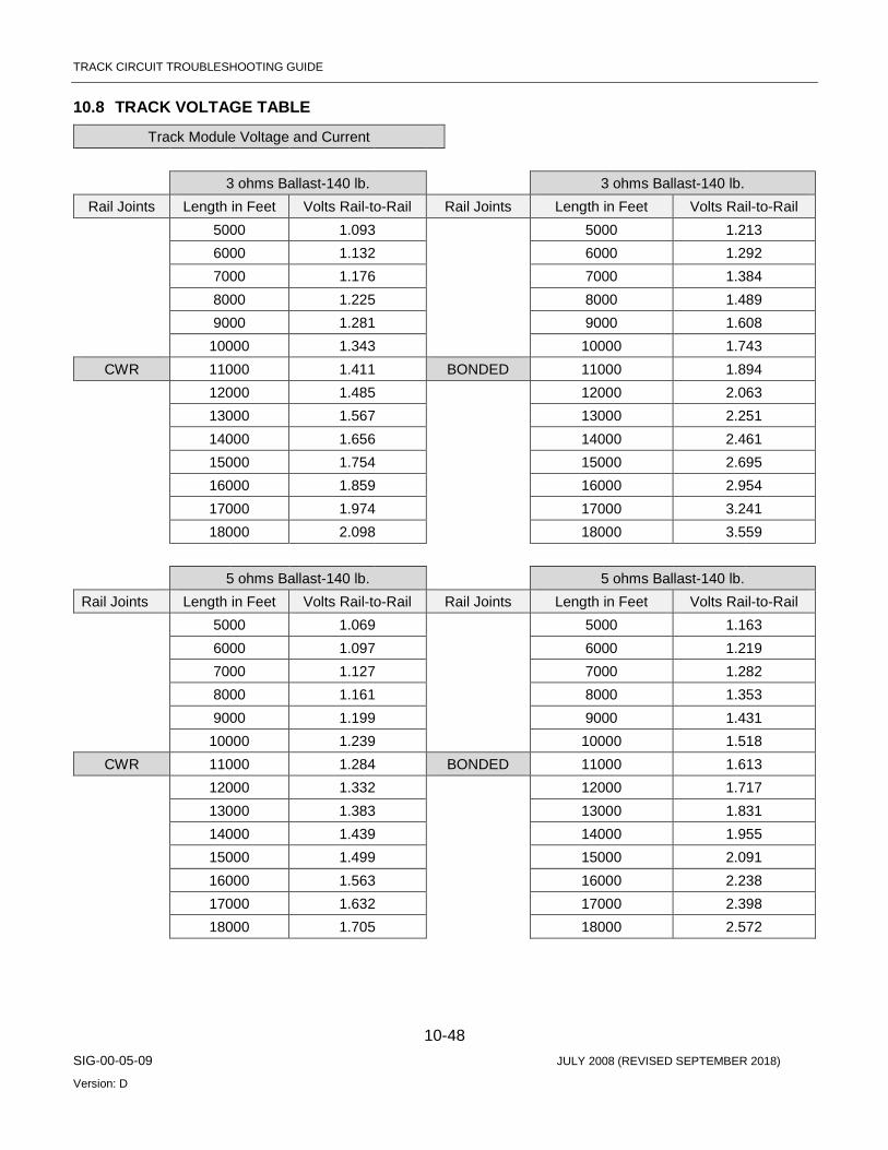
TRACK CIRCUIT TROUBLESHOOTING GUIDE
10-48 SIG-00-05-09 JULY 2008 (REVISED SEPTEMBER 2018)
Version: D
10.8 TRACK VOLTAGE TABLE
Track Module Voltage and Current 3 ohms Ballast-140 lb. 3 ohms Ballast-140 lb. Rail Joints Length in Feet Volts Rail-to-Rail Rail Joints Length in Feet Volts Rail-to-Rail
5000 1.093 5000 1.213 6000 1.132 6000 1.292 7000 1.176 7000 1.384 8000 1.225 8000 1.489 9000 1.281 9000 1.608 10000 1.343 10000 1.743
CWR 11000 1.411 BONDED 11000 1.894 12000 1.485 12000 2.063 13000 1.567 13000 2.251 14000 1.656 14000 2.461 15000 1.754 15000 2.695 16000 1.859 16000 2.954 17000 1.974 17000 3.241 18000 2.098 18000 3.559 5 ohms Ballast-140 lb. 5 ohms Ballast-140 lb. Rail Joints Length in Feet Volts Rail-to-Rail Rail Joints Length in Feet Volts Rail-to-Rail 5000 1.069 5000 1.163 6000 1.097 6000 1.219 7000 1.127 7000 1.282 8000 1.161 8000 1.353 9000 1.199 9000 1.431 10000 1.239 10000 1.518
CWR 11000 1.284 BONDED 11000 1.613 12000 1.332 12000 1.717 13000 1.383 13000 1.831 14000 1.439 14000 1.955 15000 1.499 15000 2.091 16000 1.563 16000 2.238 17000 1.632 17000 2.398 18000 1.705 18000 2.572
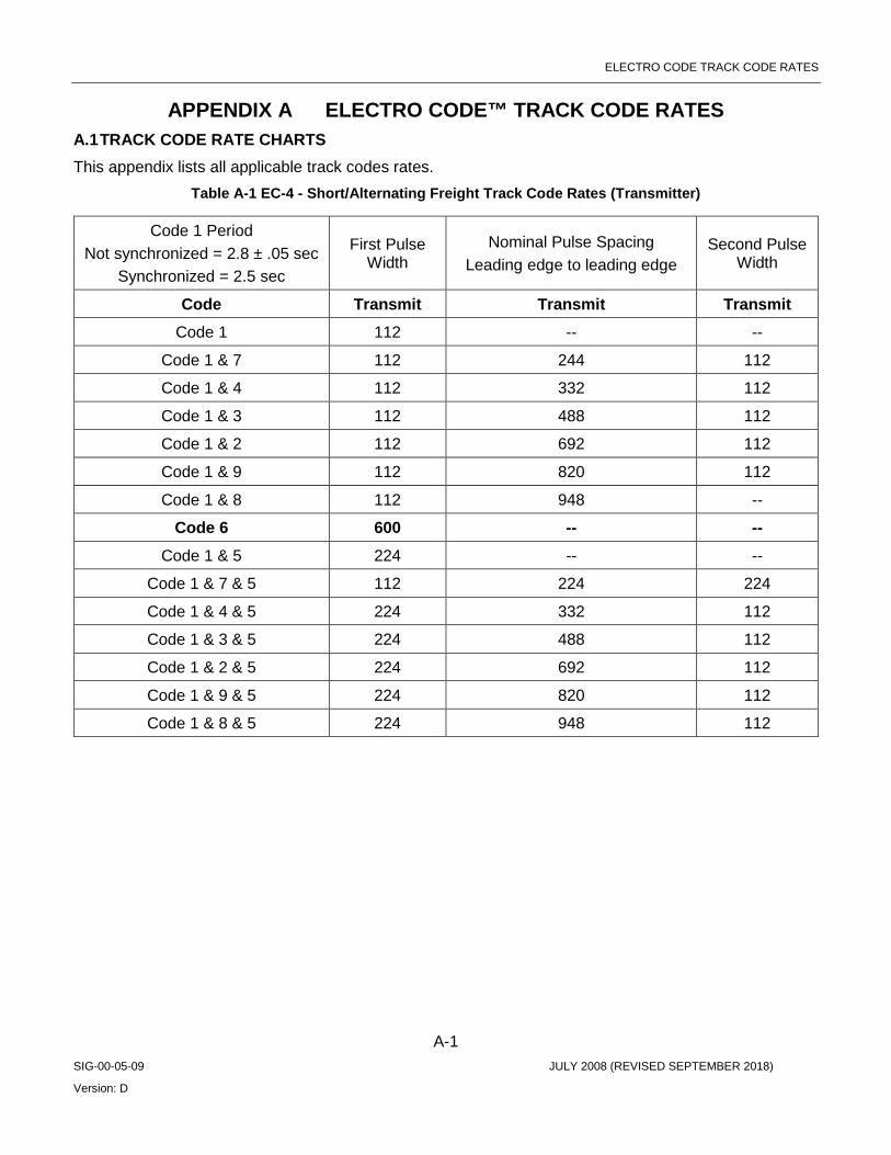
ELECTRO CODE TRACK CODE RATES
A-1 SIG-00-05-09 JULY 2008 (REVISED SEPTEMBER 2018)
Version: D
APPENDIX A ELECTRO CODE™ TRACK CODE RATES A.1 TRACK CODE RATE CHARTS This appendix lists all applicable track codes rates.
Table A-1 EC-4 - Short/Alternating Freight Track Code Rates (Transmitter)
Code 1 Period Not synchronized = 2.8 ± .05 sec
Synchronized = 2.5 sec
First Pulse Width
Nominal Pulse Spacing Leading edge to leading edge
Second Pulse Width
Code Transmit Transmit Transmit Code 1 112 -- --
Code 1 & 7 112 244 112
Code 1 & 4 112 332 112
Code 1 & 3 112 488 112
Code 1 & 2 112 692 112
Code 1 & 9 112 820 112
Code 1 & 8 112 948 --
Code 6 600 -- -- Code 1 & 5 224 -- --
Code 1 & 7 & 5 112 224 224
Code 1 & 4 & 5 224 332 112
Code 1 & 3 & 5 224 488 112
Code 1 & 2 & 5 224 692 112
Code 1 & 9 & 5 224 820 112
Code 1 & 8 & 5 224 948 112

ELECTRO CODE TRACK CODE RATES
A-2 SIG-00-05-09 JULY 2008 (REVISED SEPTEMBER 2018)
Version: D
Table A-2 EC-4 Plus—Short/Alternating Freight Track Code Rates (Transmitter)
Code 1 Period Not synchronized = 2.8 ± .05 sec
Synchronized = 2.5 sec
First Pulse Width
Nominal Pulse Spacing Leading edge to leading edge
Second Pulse Width
Code Transmit Transmit Transmit Code 1 112 -- --
Code 1 & 7 112 244 112 Code 1 & 4 112 332 112 Code 1 & 3 112 488 112 Code 1 & 2 112 692 112 Code 1 & 9 112 820 112 Code 1 & 8 112 948 --
Code 6 600 -- -- Code 1 & 5 224 -- --
Code 1 & 7 & 5 112 224 224 Code 1 & 4 & 5 224 332 112 Code 1 & 3 & 5 224 488 112 Code 1 & 2 & 5 224 692 112 Code 1 & 9 & 5 224 820 112 Code 1 & 8 & 5 224 948 112
Code 1 & M 304 -- -- Code 1 & 7 & M 112 224 304 Code 1 & 4 & M 112 332 304 Code 1 & 3 & M 112 488 304 Code 1 & 2 & M 304 692 112 Code 1 & 9 & M 304 820 112 Code 1 & 8 & M 304 948 112 Code 1 & 5 & M 264 -- --
Code 1 & 7 & 5 & M 112 224 264 Code 1 & 4 & 5 & M 112 332 264 Code 1 & 3 & 5 & M 112 488 264 Code 1 & 2 & 5 & M 264 692 112 Code 1 & 9 & 5 & M 264 820 112 Code 1 & 8 & 5 & M 264 948 112
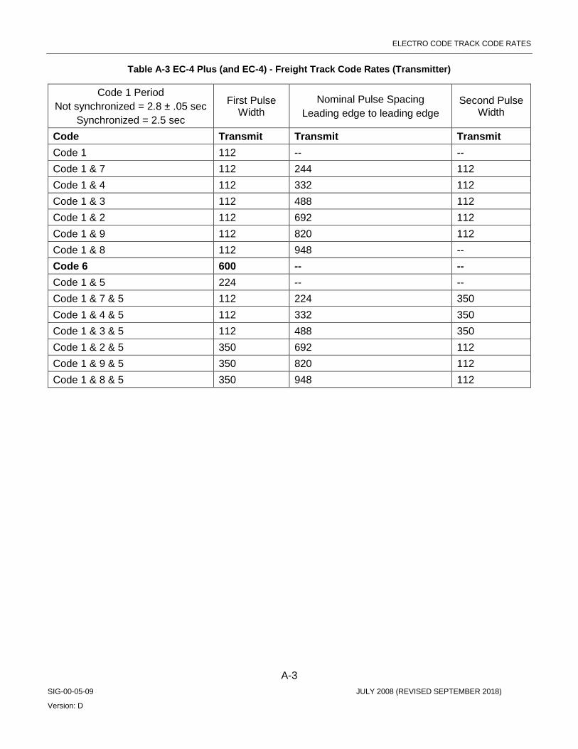
ELECTRO CODE TRACK CODE RATES
A-3 SIG-00-05-09 JULY 2008 (REVISED SEPTEMBER 2018)
Version: D
Table A-3 EC-4 Plus (and EC-4) - Freight Track Code Rates (Transmitter)
Code 1 Period Not synchronized = 2.8 ± .05 sec
Synchronized = 2.5 sec
First Pulse Width
Nominal Pulse Spacing Leading edge to leading edge
Second Pulse Width
Code Transmit Transmit Transmit Code 1 112 -- -- Code 1 & 7 112 244 112 Code 1 & 4 112 332 112 Code 1 & 3 112 488 112 Code 1 & 2 112 692 112 Code 1 & 9 112 820 112 Code 1 & 8 112 948 -- Code 6 600 -- -- Code 1 & 5 224 -- -- Code 1 & 7 & 5 112 224 350 Code 1 & 4 & 5 112 332 350 Code 1 & 3 & 5 112 488 350 Code 1 & 2 & 5 350 692 112 Code 1 & 9 & 5 350 820 112 Code 1 & 8 & 5 350 948 112

ELECTRO CODE TRACK CODE RATES
A-4 SIG-00-05-09 JULY 2008 (REVISED SEPTEMBER 2018)
Version: D
Table A-4 Freight Track Code Rates (Receiver)
First Pulse Width Pulse Spacing leading edge to leading edge Second Pulse Width
Code Minimum Maximum Minimum Maximum Minimum Maximum Code 1 62 700 -- -- -- -- Code 1 & 7 62 184 192 256 62 184 Code 1 & 4 62 184 300 364 62 184 Code 1 & 3 62 184 456 520 62 184 Code 1 & 2 62 184 660 724 62 184 Code 1 & 9 62 184 788 852 62 184 Code 1 & 8 62 184 916 980 62 184 Code 6 540 700 -- -- -- -- Code 1 & 5 184 244 -- -- -- -- Code 1 & 7 & 5 62 164 192 256 184 244 Code 1 & 4 & 5 62 164 300 364 184 244 Code 1 & 3 & 5 62 164 456 520 184 244 Code 1 & 2 & 5 184 244 660 724 62 184 Code 1 & 9 & 5 184 244 788 852 62 184 Code 1 & 8 & 5 184 244 916 980 62 184 Code 1 & M 284 344 -- -- -- -- Code 1 & 7 & M 62 184 192 256 284 344 Code 1 & 4 & M 62 184 300 364 284 344 Code 1 & 3 & M 62 184 456 520 284 344 Code 1 & 2 & M 284 344 660 724 62 184 Code 1 & 9 & M 284 344 788 852 62 184 Code 1 & 8 & M 284 344 916 980 62 184 Code 1 & 5 & M 244 284 -- -- -- -- Code 1 & 7 & 5 & M 62 184 192 256 244 284 Code 1 & 4 & 5 & M 62 184 300 364 244 284 Code 1 & 3 & 5 & M 62 184 456 520 244 284 Code 1 & 2 & 5 & M 244 284 660 724 62 184 Code 1 & 9 & 5 & M 244 284 788 852 62 184 Code 1 & 8 & 5 & M 244 284 916 980 62 184
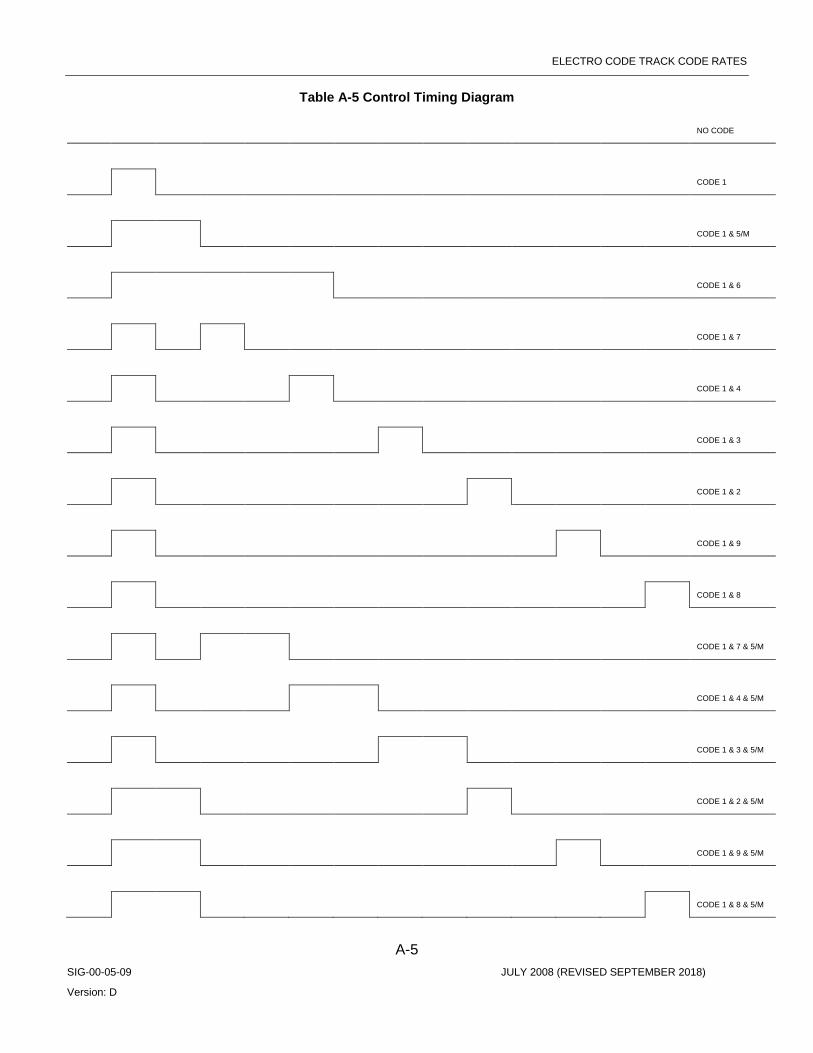
ELECTRO CODE TRACK CODE RATES
A-5 SIG-00-05-09 JULY 2008 (REVISED SEPTEMBER 2018)
Version: D
Table A-5 Control Timing Diagram
NO CODE
CODE 1
CODE 1 & 5/M
CODE 1 & 6
CODE 1 & 7
CODE 1 & 4
CODE 1 & 3
CODE 1 & 2
CODE 1 & 9
CODE 1 & 8
CODE 1 & 7 & 5/M
CODE 1 & 4 & 5/M
CODE 1 & 3 & 5/M
CODE 1 & 2 & 5/M
CODE 1 & 9 & 5/M
CODE 1 & 8 & 5/M

ELECTRO CODE TRACK CODE RATES
A-6 SIG-00-05-09 JULY 2008 (REVISED SEPTEMBER 2018)
Version: D
CODE 1 & M
CODE 1 & 5 & M
CODE 1 & 5
CODE 1 & 7 & 5
CODE 1 & 7 & 5 TO CODE 1 & 6, THEN CODE 1 & 5
CODE 1 & 7 & 5 TO CODE 1 & 6, THEN CODE 1 & 5

MODULE FAILURE DESCRIPTIONS
B-1 SIG-00-05-09 JULY 2008 (REVISED SEPTEMBER 2018)
Version: D
APPENDIX B MODULE FAILURE DESCRIPTIONS B.1 CLS MODULE Based on CLS01_12.mef
NOTE All error messages in this section will refer to “Safetran” errors, not Siemens errors.
Table B-1 CLS Module Failure Reference Table
Message Conditions Effect
"VLO Channel X1 LOR Voltage: X2 Current: X3 " X1 is failed VLO channel. X2 is VLO channel voltage. X3 is VLO channel current.
The following are failure conditions:
1. VLO current is less than threshold current. This threshold is configurable and the range is 150 to 2500 mA
2. VLO voltage is less than threshold voltage of 4000 mV
3. VLO is off during this test.
If any above condition(s) occur consecutively for threshold count, this message will be logged. The consecutive fail count threshold is set differently based on threshold current.
Set VLO status to LOR and de-energized VLO.
The software keeps testing until fault disappears.
"Safetran Error: 34 - VLO Short X1 X2 mV " (CPU II+) "Shutdown Error: 34 - VLO Short X1 X2 mV " (CPU III) When doing single lamp on (inter-channel shorts) test:
X1 is lamp channel under control and being turned on. X2 is tested lamp channel that is shorted to X1. When doing all lamps off test: X1 is failed lamp channel that is wrongly lit. X2 is set to 0.
When doing single lamp on test, if lamps are shorted is detected this message will be logged.
When doing all lamps off test, if lamp is lit is detected this message will be logged.
Set lamps status to LOR and shut down converter.
The software starts 20 seconds retry until fault disappears.
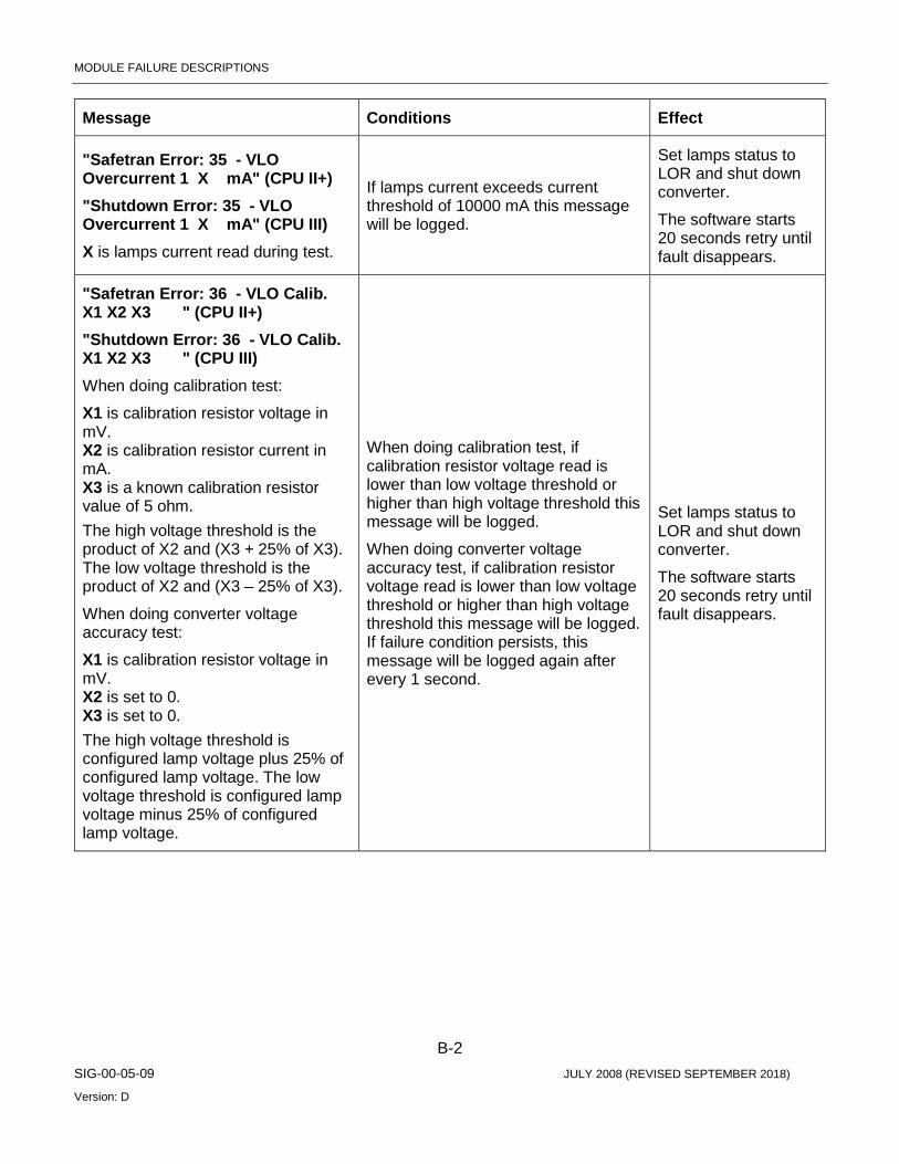
MODULE FAILURE DESCRIPTIONS
B-2 SIG-00-05-09 JULY 2008 (REVISED SEPTEMBER 2018)
Version: D
Message Conditions Effect
"Safetran Error: 35 - VLO Overcurrent 1 X mA" (CPU II+) "Shutdown Error: 35 - VLO Overcurrent 1 X mA" (CPU III) X is lamps current read during test.
If lamps current exceeds current threshold of 10000 mA this message will be logged.
Set lamps status to LOR and shut down converter.
The software starts 20 seconds retry until fault disappears.
"Safetran Error: 36 - VLO Calib. X1 X2 X3 " (CPU II+) "Shutdown Error: 36 - VLO Calib. X1 X2 X3 " (CPU III) When doing calibration test:
X1 is calibration resistor voltage in mV. X2 is calibration resistor current in mA. X3 is a known calibration resistor value of 5 ohm. The high voltage threshold is the product of X2 and (X3 + 25% of X3). The low voltage threshold is the product of X2 and (X3 – 25% of X3).
When doing converter voltage accuracy test:
X1 is calibration resistor voltage in mV. X2 is set to 0. X3 is set to 0. The high voltage threshold is configured lamp voltage plus 25% of configured lamp voltage. The low voltage threshold is configured lamp voltage minus 25% of configured lamp voltage.
When doing calibration test, if calibration resistor voltage read is lower than low voltage threshold or higher than high voltage threshold this message will be logged.
When doing converter voltage accuracy test, if calibration resistor voltage read is lower than low voltage threshold or higher than high voltage threshold this message will be logged. If failure condition persists, this message will be logged again after every 1 second.
Set lamps status to LOR and shut down converter.
The software starts 20 seconds retry until fault disappears.
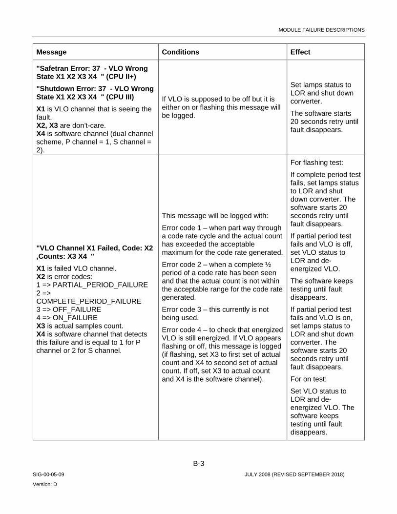
MODULE FAILURE DESCRIPTIONS
B-3 SIG-00-05-09 JULY 2008 (REVISED SEPTEMBER 2018)
Version: D
Message Conditions Effect
"Safetran Error: 37 - VLO Wrong State X1 X2 X3 X4 " (CPU II+) "Shutdown Error: 37 - VLO Wrong State X1 X2 X3 X4 " (CPU III) X1 is VLO channel that is seeing the fault. X2, X3 are don’t-care. X4 is software channel (dual channel scheme, P channel = 1, S channel = 2).
If VLO is supposed to be off but it is either on or flashing this message will be logged.
Set lamps status to LOR and shut down converter.
The software starts 20 seconds retry until fault disappears.
"VLO Channel X1 Failed, Code: X2 ,Counts: X3 X4 " X1 is failed VLO channel. X2 is error codes: 1 => PARTIAL_PERIOD_FAILURE 2 => COMPLETE_PERIOD_FAILURE 3 => OFF_FAILURE 4 => ON_FAILURE X3 is actual samples count. X4 is software channel that detects this failure and is equal to 1 for P channel or 2 for S channel.
This message will be logged with:
Error code 1 – when part way through a code rate cycle and the actual count has exceeded the acceptable maximum for the code rate generated.
Error code 2 – when a complete ½ period of a code rate has been seen and that the actual count is not within the acceptable range for the code rate generated.
Error code 3 – this currently is not being used.
Error code 4 – to check that energized VLO is still energized. If VLO appears flashing or off, this message is logged (if flashing, set X3 to first set of actual count and X4 to second set of actual count. If off, set X3 to actual count and X4 is the software channel).
For flashing test:
If complete period test fails, set lamps status to LOR and shut down converter. The software starts 20 seconds retry until fault disappears.
If partial period test fails and VLO is off, set VLO status to LOR and de-energized VLO.
The software keeps testing until fault disappears.
If partial period test fails and VLO is on, set lamps status to LOR and shut down converter. The software starts 20 seconds retry until fault disappears.
For on test:
Set VLO status to LOR and de-energized VLO. The software keeps testing until fault disappears.

MODULE FAILURE DESCRIPTIONS
B-4 SIG-00-05-09 JULY 2008 (REVISED SEPTEMBER 2018)
Version: D
Message Conditions Effect
"VLO Channel X1 Feedback failure, state X2 volts X3 " X1 is failed VLO channel. X2 is VLO state (on = 1 or off = 0). X3 is VLO channel voltage.
If VLO is on and VLO voltage is less than 4000mV, this message is logged (set X2 to 1).
If VLO is off and VLO voltage is greater than 4000mV, this message is logged (set X2 to 0).
If VLO voltage is less than 4000mV (as seen by other test), so indirectly, this could set VLO status to LOR and de-energized VLO. The software keeps testing until fault disappears.
"PWM Fail Test: X1 Voltage: X2 Current: X3 " X1 is the code of subtest which fails: 1 => check that PWM is on, but it is off. 2 => check that PWM can be turned off by controlling its voltage, but it is on. 3 => check that PWM can be turned on by controlling its voltage, but voltage out of range. 4 => check that PWM can be turned off by disabling PWM, but it is on. X2 is PWM voltage. X3 is PWM current.
This message will be logged with:
Subtest code 1 – if PWM voltage is less than 7500 mV, this message is logged (set X3 to 0).
Subtest code 2 - if PWM voltage is greater than 4000mV or PWM current is greater than 100mA.
Subtest code 3 – if PWM voltage is greater than 12500mV or less than 7500mV or PWM current is greater than 2500mA or less than 1500mA.
Subtest code 4 – if PWM voltage is greater than 4000mV or PWM current is greater than 100mA.
Module cannot start normal operation until this test is passed. The software keeps testing until fault disappears.
"Safetran Error: 38 - P/S Mismatch, Channel X " (CPU II+) "Shutdown Error: 38 - P/S Mismatch, Channel X " (CPU III) X is VLO channel seeing the mismatch.
Dual channel software disagrees on VLO status. Module reboots.

MODULE FAILURE DESCRIPTIONS
B-5 SIG-00-05-09 JULY 2008 (REVISED SEPTEMBER 2018)
Version: D
Message Conditions Effect
"Safetran Error: 39 - Current Fail, X1 X2 mA" (CPU II+) "Shutdown Error: 39 - Current Fail, X1 X2 mA" (CPU III) X1 is P/S software channel which detects this error (X1 = 1 for P channel, X1 = 2 for S channel).
X2 is VLO voltage for P software channel, or VLO current for S software channel.
During all lamps off test, if power when lamps off is greater than 2000mW, this message is logged. If above condition continues to be detected, the converter will be shut down.
Set lamps status to LOR and shut down converter.
The software starts 20 seconds retry until fault disappears.
"VLO Channel X1 Foreign Energy Detected X2 " X1 is VLO channel detecting the foreign energy.
X2 is software channel (dual channel scheme, P channel = 1, S channel = 2).
If converter is already shut down and VLO channel state is on for roughly 60 ms, then this message is logged. This message will not be logged again until foreign energy disappears and reappears.
Keep the converter down until foreign energy disappears.
The software keeps testing until fault disappears.
"Safetran Error: 0 - VLO cycle time " (CPU II+) "Shutdown Error: 0 - VLO cycle time " (CPU III)
If the software does not read and empty the VLOs samples buffer when it is scheduled to, this message will be logged.
Module reboots.

MODULE FAILURE DESCRIPTIONS
B-6 SIG-00-05-09 JULY 2008 (REVISED SEPTEMBER 2018)
Version: D
Message Conditions Effect
"VRO Channel X1 Failed, Code: X2 ,Counts: X3 X4 " X1 is failed VRO channel.
X2 is error codes:
1 => SELF_CHECK_FAIL
2 => CHECK_PERIOD_TEST_FAIL
3 => START_UP_CHECK_STATE_FAIL
4 => PARTIAL_CHECK_PERIOD_FAIL
5 => OFF_STATE_FAIL
6 => ON_STATE_FAIL
X3 is actual samples count.
X4 is software channel that detects this failure and is equal to 1 for P channel or 2 for S channel.
This message will be logged with:
Error code 1 – during performing self test, if number of test samples of de-energized state is less than expected test samples (= 1).
Error code 2 – when a complete 1/2 period of a code rate has been seen and that the actual count is not within the acceptable range for the code rate generated.
Error code 3 – to check that VRO is commanded from off to on/coded or from on/coded/coded to coded/on/coded respectively within specified time (roughly in 1 second). If it is not within that time, this message is logged (X3 is schedule count).
Error code 4 – when part way through a code rate cycle, if the actual count has exceeded the acceptable maximum for the code rate generated.
Error code 5 – de-energized VROs appear flashing or on, (set X3 to 0 if flashing and to actual count if on).
Error code 6 – If VRO appears flashing or off when VRO is on, then message is logged (set X3 to 0 if flashing and to actual count if off).
Set VRO status to failed, turn off failed VRO, and open failed VRO output switch.
The software starts 5 second retry until fault disappears.
"Safetran Error: 31 - VRO cycle time " (CPU II+) "Shutdown Error: 31 - VRO cycle time " (CPU III)
If the software does not read and empty the VRO’s samples buffer when it is scheduled to, this message will be logged.
Module reboots.
"Safetran Error: 32 - VRO P/S Mismatch channel X " (CPU II+) "Shutdown Error: 32 - VRO P/S Mismatch channel X " (CPU III) X is VRO channel that is seeing the mismatch.
If the VRO output status disagrees between P and S channel (software channel), this message will be logged.
Module reboots.

MODULE FAILURE DESCRIPTIONS
B-7 SIG-00-05-09 JULY 2008 (REVISED SEPTEMBER 2018)
Version: D
Message Conditions Effect
"Safetran Error: 33 - VRO fail channel X " (CPU II+) "Shutdown Error: 33 - VRO fail channel X " (CPU III) X is failed VRO channel.
This test is to check that failed VRO are still de-energized. If VRO appears flashing or on, this message is logged.
Module reboots.
"Safetran Error: 29 - VPI hw fail channel X " (CPU II+) "Shutdown Error: 29 - VPI hw fail channel X " (CPU III) X is failed VPI channel.
During self-test, the VPI channel is shorted during which a sample is taken and if the state of this sample is not de-energized this message is logged.
Module reboots.
"Safetran Error: 30 - VPI cycle time " (CPU II+) "Shutdown Error: 30 - VPI cycle time " (CPU III)
If the software does not read and empty the VPI’s samples buffer when it is scheduled to, this message will be logged.
Module reboots.
B.2 LIN MODULE Based on LIN00_17.mef
Table B-2 LIN Module Failure Reference Table
Message Conditions Effect
"TRK Reference Voltage Error: Nom= X1 mV Act= X2 mV" X1 is nominal reference voltage of 2500 mV.
X2 is actual reading of the reference voltage source of 2.5 V.
When taking reading of requested transmitter voltage, VCO voltages, or VCO currents, this reference voltage is also read. If this reference voltage is out of range this message is logged.
Sets reading of requested transmitter voltage, VCO voltages, or VCO currents to zeros. The tests that use these readings will act accordingly.
"Safetran Error: 0 - TRK Dual Channel Mismatch "
If Dual channel software disagrees on line cycles or cycle count, this message is logged.
Module reboots.
"TRK Code Illegal Commanded ( ): "
If illegal TRK codes are commanded, this message will be logged.
Transmits TRK code “1”. Flashes health LED at fail flash rate.

MODULE FAILURE DESCRIPTIONS
B-8 SIG-00-05-09 JULY 2008 (REVISED SEPTEMBER 2018)
Version: D
Message Conditions Effect
"TRK VCO Voltage Fail( X1):Act= X2 Min\Max= X3 X4 " X1 is software channel that detects this failure (P channel = 1, S channel = 2).
X2 is actual line output voltage.
Active VCO voltage is user configured VCO voltage plus 500mV that is compensated for diode drop.
Configured receive threshold is user configured receive threshold unless user configured VCO voltage is less than or equal to user configured receive threshold plus 1000mV, then configured receive threshold is user configured VCO voltage minus 1000mV.
When transmitter is on:
X3 is low threshold voltage. If active VCO voltage is less than 4000 mV, this threshold voltage is 0 mV. If active VCO voltage is greater than or equal to 4000 mV, this threshold voltage is active VCO voltage minus 4000 mV.
X4 is high threshold voltage of active VCO voltage plus 4000 mV.
When transmitter is off:
X3 is don’t-care and set at 0 mV.
X4 is don’t-care and set at 2000mv.
The actual threshold voltage is assigned half the configured receive threshold and if this actual threshold voltage is less than 2000mV, it is re-assigned 2000mV.
While transmitter is on, if line output voltage is less than X3 or greater than X4 for roughly 7.5 seconds this message is logged.
While transmitter is off, if line output voltage is greater than actual threshold voltage in roughly 1.25 seconds or less, this message is logged.
For transmitter on test:
Transmitter shutdowns: Sets transmitter fail status bit, shutdowns converter and flashes health LED at fail flash rate. The software starts 10 seconds retry until fault disappears.
For transmitter off test:
Transmitter shutdowns: Sets transmitter fail status bit, shutdowns converter and flashes health LED at fail flash rate. The software starts 10 seconds retry until fault disappears.
Receiver shutdowns: Sets receiver fail status bit, indicates no code received to CPU, and flashes health LED at fail flash rate. The software starts 10 seconds retry until fault disappears.

MODULE FAILURE DESCRIPTIONS
B-9 SIG-00-05-09 JULY 2008 (REVISED SEPTEMBER 2018)
Version: D
Message Conditions Effect
"TRK DAC Voltage Fail( X1 ):Act= X2 Min\Max= X3 X4 " X1 is software channel that detects this failure (P channel = 1, S channel = 2).
X2 is the requested transmitter voltage.
Active VCO voltage is user configured VCO voltage plus 500mV that is compensated for diode drop.
X3 is low threshold voltage. If active VCO voltage is less than 800 mV, this threshold voltage is 0 mV. If active VCO voltage is greater than or equal to 800 mV, this threshold voltage is active VCO voltage minus 800 mV.
X4 is high threshold voltage of active VCO voltage plus 800 mV.
If the Track voltage is outside the expected range for roughly 1.25 seconds, this message is logged.
Transmitter shutdowns: Sets transmitter fail status bit, shutdowns converter and flashes health LED at fail flash rate. The software starts 10 seconds retry until fault disappears.
"TRK VCO Current Fail( X1 ): I1= X2 mA, I2= X3 mA " X1 is software channel that detects this failure (P channel = 1, S channel = 2).
X2 is line output current 1.
X3 is line output current 2.
If current 1 is greater than 250 mA and difference between current 1 and current 2 is greater than 20% of current 1 for roughly 7.5 seconds this message is logged.
Transmitter shutdowns: Sets transmitter fail status bit, shutdowns converter and flashes health LED at fail flash rate. The software starts 10 seconds retry until fault disappears.
"Safetran Error: 43 - TRACK Transmit Shutdown Failure"
If transmitter failure occurrences due to any cause have reached 100 times, this message is logged.
Module reboots.
"Safetran Error: 44 - TRACK Transmitter On Failure "
When transmitter is on, if requested transmitter voltage falls outside the expected range for roughly 24 ms, this message is logged.
This test is performed during transmit cycle.
Module reboots.
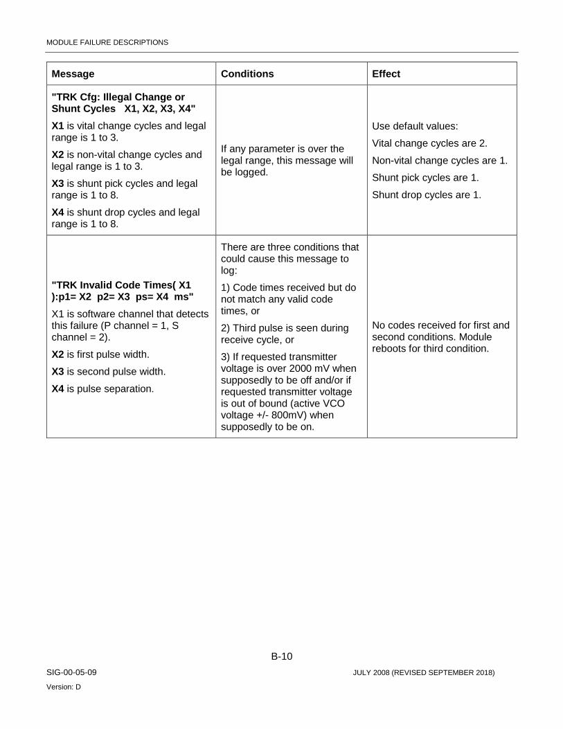
MODULE FAILURE DESCRIPTIONS
B-10 SIG-00-05-09 JULY 2008 (REVISED SEPTEMBER 2018)
Version: D
Message Conditions Effect
"TRK Cfg: Illegal Change or Shunt Cycles X1, X2, X3, X4" X1 is vital change cycles and legal range is 1 to 3.
X2 is non-vital change cycles and legal range is 1 to 3.
X3 is shunt pick cycles and legal range is 1 to 8.
X4 is shunt drop cycles and legal range is 1 to 8.
If any parameter is over the legal range, this message will be logged.
Use default values:
Vital change cycles are 2.
Non-vital change cycles are 1.
Shunt pick cycles are 1.
Shunt drop cycles are 1.
"TRK Invalid Code Times( X1 ):p1= X2 p2= X3 ps= X4 ms" X1 is software channel that detects this failure (P channel = 1, S channel = 2).
X2 is first pulse width.
X3 is second pulse width.
X4 is pulse separation.
There are three conditions that could cause this message to log:
1) Code times received but do not match any valid code times, or
2) Third pulse is seen during receive cycle, or
3) If requested transmitter voltage is over 2000 mV when supposedly to be off and/or if requested transmitter voltage is out of bound (active VCO voltage +/- 800mV) when supposedly to be on.
No codes received for first and second conditions. Module reboots for third condition.

MODULE FAILURE DESCRIPTIONS
B-11 SIG-00-05-09 JULY 2008 (REVISED SEPTEMBER 2018)
Version: D
Message Conditions Effect
"TRK HES Digital Level Failure ( X1 ): P,Q= X2 mV" X1 is software channel that detects this failure (P channel = 1, S channel = 2).
Configured receive threshold is user configured receive threshold unless user configured VCO voltage is less than or equal to user configured receive threshold plus 1000mV, then configured receive threshold is user configured VCO voltage minus 1000mV.
X2 is receiver voltage level (1=High, or 0=Low). If line receive voltage (same channel as transmit voltage) is greater than configured receive threshold, set X2 to High else set X2 to Low.
During transmit cycle, when transmitter is on, if receiver voltage level is Low, or when transmitter is off, if receiver voltage level is High, this message is logged.
Transmitter shutdowns: Sets transmitter fail status bit, shutdowns converter, and flashes health LED at fail flash rate. The software starts 10 seconds retry until fault disappears.
Receiver shutdowns: Sets receiver fail status bit, indicates no code received to CPU, and flashes health LED at fail flash rate. The software starts 10 seconds retry until fault disappears.
"Safetran Error: 54 - TRACK Receive Shutdown Failure "
If receiver failure occurrences due to any cause have reached 100 times, this message is logged.
Module reboots.
"LINE Avg Voltage Failure: V X1 Last_V X2 X3 " X1 is current average line output voltage.
X2 is last average line output voltage.
Each average voltage is the average of 8 samples.
X3 is set to 1 (P channel software).
While transmitter is on, if average line output voltage is below ½ the last average line output voltage or below 2000 mV, this message is logged.
Transmitter shutdowns: Sets transmitter fail status bit, shutdowns converter and flashes health LED at fail flash rate. The software starts 10 seconds retry until fault disappears.
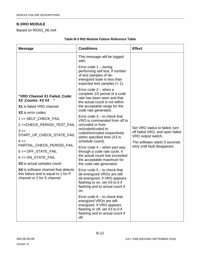
MODULE FAILURE DESCRIPTIONS
B-12 SIG-00-05-09 JULY 2008 (REVISED SEPTEMBER 2018)
Version: D
B.3 RIO MODULE Based on RIO01_06.mef
Table B-3 RIO Module Failure Reference Table
Message Conditions Effect
"VRO Channel X1 Failed, Code: X2 ,Counts: X3 X4 " X1 is failed VRO channel.
X2 is error codes:
1 => SELF_CHECK_FAIL
2 =>CHECK_PERIOD_TEST_FAIL
3 => START_UP_CHECK_STATE_FAIL
4 => PARTIAL_CHECK_PERIOD_FAIL
5 => OFF_STATE_FAIL
6 => ON_STATE_FAIL
X3 is actual samples count.
X4 is software channel that detects this failure and is equal to 1 for P channel or 2 for S channel.
This message will be logged with:
Error code 1 – during performing self test, if number of test samples of de-energized state is less than expected test samples (= 1).
Error code 2 – when a complete 1/2 period of a code rate has been seen and that the actual count is not within the acceptable range for the code rate generated.
Error code 3 – to check that VRO is commanded from off to on/coded or from on/coded/coded to coded/on/coded respectively within specified time (X3 is schedule count).
Error code 4 – when part way through a code rate cycle, if the actual count has exceeded the acceptable maximum for the code rate generated.
Error code 5 – to check that de-energized VROs are still de-energized. If VRO appears flashing or on, set X3 to 0 if flashing and to actual count if on.
Error code 6 – to check that energized VROs are still energized. If VRO appears flashing or off, set X3 to 0 if flashing and to actual count if off.
Set VRO status to failed, turn off failed VRO, and open failed VRO output switch.
The software starts 5 seconds retry until fault disappears.
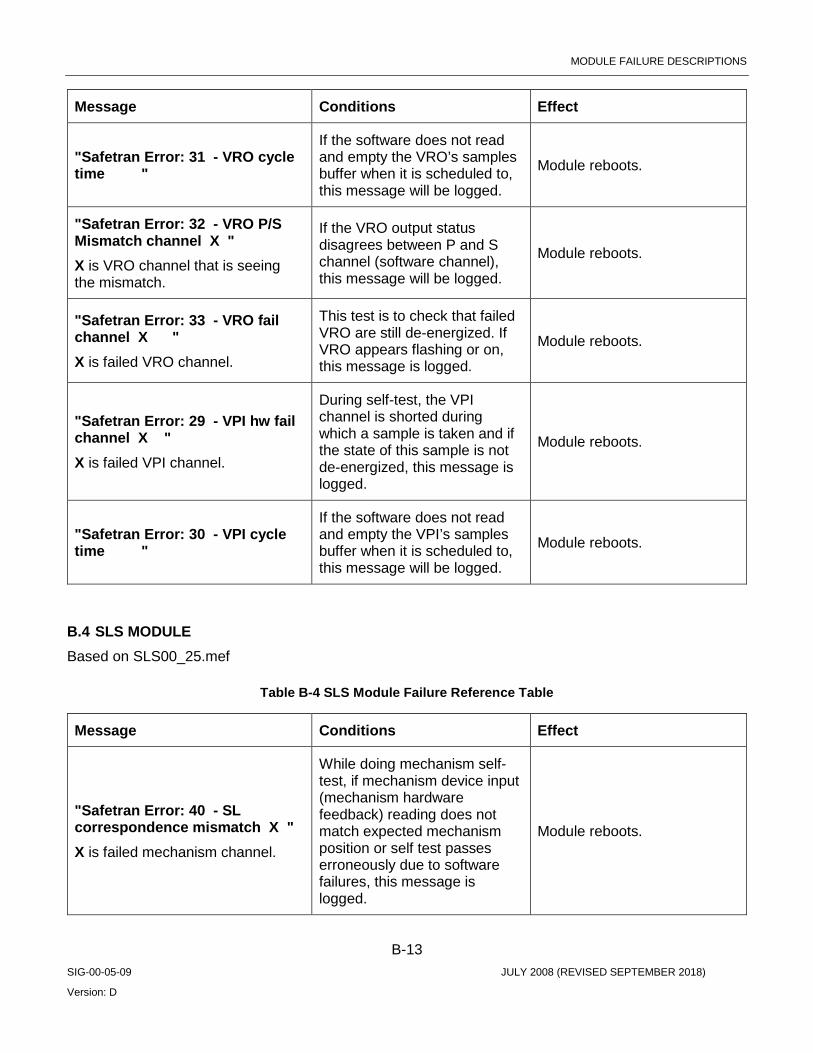
MODULE FAILURE DESCRIPTIONS
B-13 SIG-00-05-09 JULY 2008 (REVISED SEPTEMBER 2018)
Version: D
Message Conditions Effect
"Safetran Error: 31 - VRO cycle time "
If the software does not read and empty the VRO’s samples buffer when it is scheduled to, this message will be logged.
Module reboots.
"Safetran Error: 32 - VRO P/S Mismatch channel X " X is VRO channel that is seeing the mismatch.
If the VRO output status disagrees between P and S channel (software channel), this message will be logged.
Module reboots.
"Safetran Error: 33 - VRO fail channel X " X is failed VRO channel.
This test is to check that failed VRO are still de-energized. If VRO appears flashing or on, this message is logged.
Module reboots.
"Safetran Error: 29 - VPI hw fail channel X " X is failed VPI channel.
During self-test, the VPI channel is shorted during which a sample is taken and if the state of this sample is not de-energized, this message is logged.
Module reboots.
"Safetran Error: 30 - VPI cycle time "
If the software does not read and empty the VPI’s samples buffer when it is scheduled to, this message will be logged.
Module reboots.
B.4 SLS MODULE Based on SLS00_25.mef
Table B-4 SLS Module Failure Reference Table
Message Conditions Effect
"Safetran Error: 40 - SL correspondence mismatch X " X is failed mechanism channel.
While doing mechanism self-test, if mechanism device input (mechanism hardware feedback) reading does not match expected mechanism position or self test passes erroneously due to software failures, this message is logged.
Module reboots.

MODULE FAILURE DESCRIPTIONS
B-14 SIG-00-05-09 JULY 2008 (REVISED SEPTEMBER 2018)
Version: D
Message Conditions Effect
"SL red correspondence test failed ,channel: X " X is failed mechanism channel.
During red position mechanism check, if mechanism device input does not indicate red, then this message is logged. This message only logs once if it stays in failed mode.
Set card in failed mode: command VLO to off, command mechanism position to red, set mech. position status to red, and indicate mech. failed to CPU.
The software starts 10 seconds retry until fault disappears.
"SL yellow correspondence test failed, channel: X " X is failed mechanism channel.
During yellow position mechanism check, if mechanism device input indicates position other than yellow and no position (no position means not settle in any position and not invalid positions) then this message is logged. This message only logs once if it stays in failed mode.
Set card in failed mode: command VLO to off, command mechanism position to red, set mech. position status to red, and indicate mech. failed to CPU.
The software starts 10 seconds retry until fault disappears.
"SL green correspondence test failed ,channel: X " X is failed mechanism channel.
During green position mechanism check, if mechanism device input indicates position other than green and no position (no position means not settle in any position and not invalid positions) then this message is logged. This message only logs once if it stays in failed mode.
Set card in failed mode: command VLO to off, command mechanism position to red, set mech. position status to red, and indicate mech. failed to CPU.
The software starts 10 seconds retry until fault disappears.
"SL correspondence test failed ,channel: X " X is failed mechanism channel.
During last stage of mech. Self-test, if mechanism device input does not indicate red position then this message is logged.
Set card in failed mode: command VLO to off, command mechanism position to red, set mech. position status to red, and indicate mech. failed to CPU.
The software starts 10 seconds retry until fault disappears.
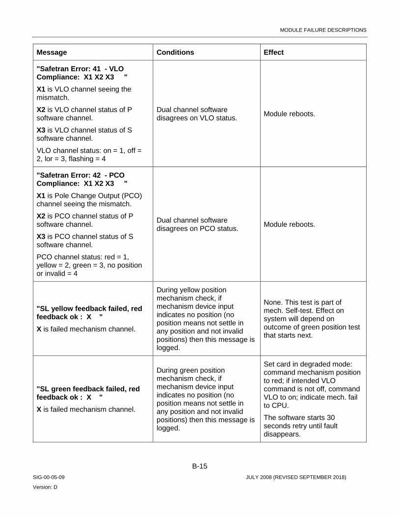
MODULE FAILURE DESCRIPTIONS
B-15 SIG-00-05-09 JULY 2008 (REVISED SEPTEMBER 2018)
Version: D
Message Conditions Effect
"Safetran Error: 41 - VLO Compliance: X1 X2 X3 " X1 is VLO channel seeing the mismatch.
X2 is VLO channel status of P software channel.
X3 is VLO channel status of S software channel.
VLO channel status: on = 1, off = 2, lor = 3, flashing = 4
Dual channel software disagrees on VLO status. Module reboots.
"Safetran Error: 42 - PCO Compliance: X1 X2 X3 " X1 is Pole Change Output (PCO) channel seeing the mismatch.
X2 is PCO channel status of P software channel.
X3 is PCO channel status of S software channel.
PCO channel status: red = 1, yellow = 2, green = 3, no position or invalid = 4
Dual channel software disagrees on PCO status. Module reboots.
"SL yellow feedback failed, red feedback ok : X " X is failed mechanism channel.
During yellow position mechanism check, if mechanism device input indicates no position (no position means not settle in any position and not invalid positions) then this message is logged.
None. This test is part of mech. Self-test. Effect on system will depend on outcome of green position test that starts next.
"SL green feedback failed, red feedback ok : X " X is failed mechanism channel.
During green position mechanism check, if mechanism device input indicates no position (no position means not settle in any position and not invalid positions) then this message is logged.
Set card in degraded mode: command mechanism position to red; if intended VLO command is not off, command VLO to on; indicate mech. fail to CPU.
The software starts 30 seconds retry until fault disappears.

MODULE FAILURE DESCRIPTIONS
B-16 SIG-00-05-09 JULY 2008 (REVISED SEPTEMBER 2018)
Version: D
Message Conditions Effect
"PCO Channel X1 Correspondence Failure : X2 " X1 is failed mechanism channel.
X2 is mechanism device input reading.
If mechanism device input does not match commanded mech. position then this message is logged.
None. Upper layer software will evaluate this failure and act accordingly.
"VLO Channel X1 LOR Voltage: X2 Current: X3 " X1 is failed VLO channel.
X2 is VLO channel voltage.
X3 is VLO channel current.
The following are failure conditions:
4) VLO current is less than threshold current (=600 mA).
5) VLO voltage is less than threshold voltage. This threshold voltage is half the configured lamp voltage.
6) VLO is off during this test.
If any above condition(s) occur, this message will be logged.
Set VLO status to LOR and de-energized VLO.
The software keeps testing until fault disappears.
"Safetran Error: 34 - VLO Short X1 X2 mV " When doing single lamp on (inter-channel shorts) test:
X1 is lamp channel under control and being turned on.
X2 is tested lamp channel that is shorted to X1.
When doing all lamps off test:
X1 is failed lamp channel that is wrongly lit.
X2 is set to 0.
When doing single lamp on test, if lamps are shorted is detected, this message will be logged.
When doing all lamps off test, if lamp is lit is detected, this message will be logged.
Set lamps status to LOR and shut down converter.
The software starts 20 seconds retry until fault disappears.
"Safetran Error: 35 - VLO Overcurrent 1 X mA" X is lamps current read during test.
If lamps current exceeds current threshold of 8000 mA, this message will be logged.
Set lamps status to LOR and shut down converter.
The software starts 20 seconds retry until fault disappears.

MODULE FAILURE DESCRIPTIONS
B-17 SIG-00-05-09 JULY 2008 (REVISED SEPTEMBER 2018)
Version: D
Message Conditions Effect
"Safetran Error: 36 - VLO Calib. X1 X2 X3 " When doing calibration test:
X1 is calibration resistor voltage in mV.
X2 is calibration resistor current in mA.
X3 is a known calibration resistor value of 5 ohm.
The high voltage threshold is the product of X2 and (X3 + 20% of X3). The low voltage threshold is the product of X2 and (X3 – 20% of X3).
When doing converter voltage accuracy test:
X1 is calibration resistor voltage in mV.
X2 is set to 0.
X3 is set to 0.
The high voltage threshold is configured lamp voltage plus 20% of configured lamp voltage. The low voltage threshold is configured lamp voltage minus 20% of configured lamp voltage.
When doing calibration test, if calibration resistor voltage read is lower than low voltage threshold or higher than high voltage threshold for one time (within 2 seconds), this message will be logged. Failure for the second time in sequence will result in shutdown of the lamp converter.
When doing converter voltage accuracy test, if calibration resistor voltage read is lower than low voltage threshold or higher than high voltage threshold for one time (within 2 seconds), this message will be logged. Failure for the second time in sequence will result in shutdown of the lamp converter.
Set lamps status to LOR and shut down converter.
The software starts 20 seconds retry until fault disappears.
"Safetran Error: 37 - VLO Wrong State X1 X2 X3 X4 " X1 is VLO channel that is seeing the fault.
X2, X3 are don’t-care.
X4 is software channel (dual channel scheme, P channel = 1, S channel = 2).
If VLO is supposed to be off but it is either on or flashing, this message will be logged.
Set lamps status to LOR and shut down converter.
The software starts 20 seconds retry until fault disappears.
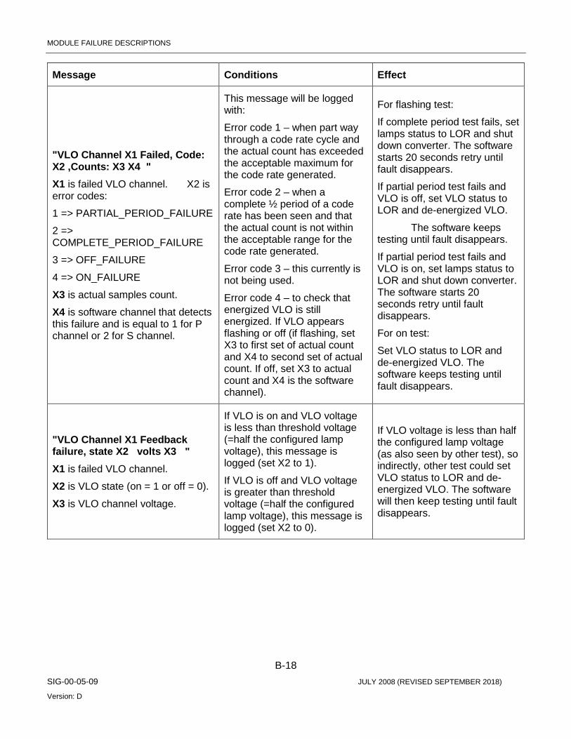
MODULE FAILURE DESCRIPTIONS
B-18 SIG-00-05-09 JULY 2008 (REVISED SEPTEMBER 2018)
Version: D
Message Conditions Effect
"VLO Channel X1 Failed, Code: X2 ,Counts: X3 X4 " X1 is failed VLO channel. X2 is error codes:
1 => PARTIAL_PERIOD_FAILURE
2 => COMPLETE_PERIOD_FAILURE
3 => OFF_FAILURE
4 => ON_FAILURE
X3 is actual samples count.
X4 is software channel that detects this failure and is equal to 1 for P channel or 2 for S channel.
This message will be logged with:
Error code 1 – when part way through a code rate cycle and the actual count has exceeded the acceptable maximum for the code rate generated.
Error code 2 – when a complete ½ period of a code rate has been seen and that the actual count is not within the acceptable range for the code rate generated.
Error code 3 – this currently is not being used.
Error code 4 – to check that energized VLO is still energized. If VLO appears flashing or off (if flashing, set X3 to first set of actual count and X4 to second set of actual count. If off, set X3 to actual count and X4 is the software channel).
For flashing test:
If complete period test fails, set lamps status to LOR and shut down converter. The software starts 20 seconds retry until fault disappears.
If partial period test fails and VLO is off, set VLO status to LOR and de-energized VLO.
The software keeps testing until fault disappears.
If partial period test fails and VLO is on, set lamps status to LOR and shut down converter. The software starts 20 seconds retry until fault disappears.
For on test:
Set VLO status to LOR and de-energized VLO. The software keeps testing until fault disappears.
"VLO Channel X1 Feedback failure, state X2 volts X3 " X1 is failed VLO channel.
X2 is VLO state (on = 1 or off = 0).
X3 is VLO channel voltage.
If VLO is on and VLO voltage is less than threshold voltage (=half the configured lamp voltage), this message is logged (set X2 to 1).
If VLO is off and VLO voltage is greater than threshold voltage (=half the configured lamp voltage), this message is logged (set X2 to 0).
If VLO voltage is less than half the configured lamp voltage (as also seen by other test), so indirectly, other test could set VLO status to LOR and de-energized VLO. The software will then keep testing until fault disappears.
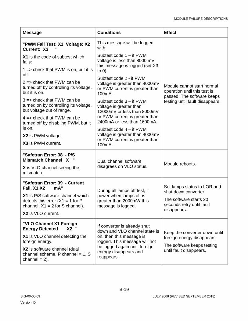
MODULE FAILURE DESCRIPTIONS
B-19 SIG-00-05-09 JULY 2008 (REVISED SEPTEMBER 2018)
Version: D
Message Conditions Effect
"PWM Fail Test: X1 Voltage: X2 Current: X3 " X1 is the code of subtest which fails:
1 => check that PWM is on, but it is off.
2 => check that PWM can be turned off by controlling its voltage, but it is on.
3 => check that PWM can be turned on by controlling its voltage, but voltage out of range.
4 => check that PWM can be turned off by disabling PWM, but it is on.
X2 is PWM voltage.
X3 is PWM current.
This message will be logged with:
Subtest code 1 – if PWM voltage is less than 8000 mV, this message is logged (set X3 to 0).
Subtest code 2 - if PWM voltage is greater than 4000mV or PWM current is greater than 100mA.
Subtest code 3 – if PWM voltage is greater than 12000mV or less than 8000mV or PWM current is greater than 2400mA or less than 1600mA.
Subtest code 4 – if PWM voltage is greater than 4000mV or PWM current is greater than 100mA.
Module cannot start normal operation until this test is passed. The software keeps testing until fault disappears.
"Safetran Error: 38 - P/S Mismatch,Channel X " X is VLO channel seeing the mismatch.
Dual channel software disagrees on VLO status. Module reboots.
"Safetran Error: 39 - Current Fail, X1 X2 mA" X1 is P/S software channel which detects this error (X1 = 1 for P channel, X1 = 2 for S channel).
X2 is VLO current.
During all lamps off test, if power when lamps off is greater than 2000mW this message is logged.
Set lamps status to LOR and shut down converter.
The software starts 20 seconds retry until fault disappears.
"VLO Channel X1 Foreign Energy Detected X2 " X1 is VLO channel detecting the foreign energy.
X2 is software channel (dual channel scheme, P channel = 1, S channel = 2).
If converter is already shut down and VLO channel state is on, then this message is logged. This message will not be logged again until foreign energy disappears and reappears.
Keep the converter down until foreign energy disappears.
The software keeps testing until fault disappears.

MODULE FAILURE DESCRIPTIONS
B-20 SIG-00-05-09 JULY 2008 (REVISED SEPTEMBER 2018)
Version: D
Message Conditions Effect
"VRO Channel X1 Failed, Code: X2 ,Counts: X3 X4 " X1 is failed VRO channel.
X2 is error codes:
1 => SELF_CHECK_FAIL
2 => CHECK_PERIOD_TEST_FAIL
3 => START_UP_CHECK_STATE_FAIL
4 => PARTIAL_CHECK_PERIOD_FAIL
5 => OFF_STATE_FAIL
6 => ON_STATE_FAIL
X3 is actual samples count.
X4 is software channel that detects this failure and is equal to 1 for P channel or 2 for S channel.
This message will be logged with:
Error code 1 – during performing self-test, if number of test samples of de-energized state is less than expected test samples (= 1).
Error code 2 – when a complete 1/2 period of a code rate has been seen and that the actual count is not within the acceptable range for the code rate generated.
Error code 3 – to check that VRO is commanded from off to on/coded or from on/coded/coded to coded/on/coded respectively within specified time (roughly in 1 second). If it is not within that time, message is logged (X3 is schedule count).
Error code 4 – when part way through a code rate cycle, if the actual count has exceeded the acceptable maximum for the code rate generated.
Error code 5 – to check that de-energized VROs are still de-energized. If VRO appears flashing or on (set X3 to 0 if flashing and to actual count if on).
Error code 6 – to check that energized VROs are still energized. If VRO appears flashing or off (set X3 to 0 if flashing and to actual count if off).
Set VRO status to failed, turn off failed VRO, and open failed VRO output switch.
The software starts 5 seconds retry until fault disappears.
"Safetran Error: 31 - VRO cycle time "
If the software does not read and empty the VRO’s samples buffer when it is scheduled to, this message will be logged.
Module reboots.

MODULE FAILURE DESCRIPTIONS
B-21 SIG-00-05-09 JULY 2008 (REVISED SEPTEMBER 2018)
Version: D
Message Conditions Effect
"Safetran Error: 32 - VRO P/S Mismatch channel X " X is VRO channel that is seeing the mismatch.
If the VRO output status disagrees between P and S channel (software channel), this message will be logged.
Module reboots.
"Safetran Error: 33 - VRO fail channel X " X is failed VRO channel.
This test is to check that failed VRO are still de-energized. If VRO appears flashing or on, this message is logged.
Module reboots.
"Safetran Error: 29 - VPI hw fail channel X " X is failed VPI channel.
During self-test, the VPI channel is shorted during which a sample is taken and if the state of this sample is not de-energized, this message is logged.
Module reboots.
"Safetran Error: 30 - VPI cycle time "
If the software does not read and empty the VPI’s samples buffer when it is scheduled to, this message will be logged.
Module reboots.
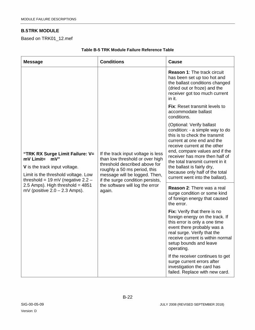
MODULE FAILURE DESCRIPTIONS
B-22 SIG-00-05-09 JULY 2008 (REVISED SEPTEMBER 2018)
Version: D
B.5 TRK MODULE Based on TRK01_12.mef
Table B-5 TRK Module Failure Reference Table
Message Conditions Cause
“TRK RX Surge Limit Failure: V= mV Limit= mV” V is the track input voltage.
Limit is the threshold voltage. Low threshold = 19 mV (negative 2.2 – 2.5 Amps). High threshold = 4851 mV (positive 2.0 – 2.3 Amps).
If the track input voltage is less than low threshold or over high threshold described above for roughly a 50 ms period, this message will be logged. Then, if the surge condition persists, the software will log the error again.
Reason 1: The track circuit has been set up too hot and the ballast conditions changed (dried out or froze) and the receiver got too much current in it.
Fix: Reset transmit levels to accommodate ballast conditions.
(Optional: Verify ballast condition: - a simple way to do this is to check the transmit current at one end and the receive current at the other end, compare values and if the receiver has more then half of the total transmit current in it the ballast is fairly dry, because only half of the total current went into the ballast).
Reason 2: There was a real surge condition or some kind of foreign energy that caused the error.
Fix: Verify that there is no foreign energy on the track. If this error is only a one time event there probably was a real surge. Verify that the receive current is within normal setup bounds and leave operating.
If the receiver continues to get surge current errors after investigation the card has failed. Replace with new card.

MODULE FAILURE DESCRIPTIONS
B-23 SIG-00-05-09 JULY 2008 (REVISED SEPTEMBER 2018)
Version: D
Message Conditions Cause
Effect: Receiver shuts down: Sets receiver fail status bit, indicates no code received to CPU and opens receiver switch.
Transmitter shuts down: Sets transmitter fail status bit, turns off transmit voltage, and opens transmit switch.
The software starts 10 seconds retry until fault disappears.
"Safetran Error: 61 - TRACK Config Failure Code 5 "
If illegal Code 5 Mode configuration is commanded, this message will be logged.
MCF/MEF bug. Consult Siemens.
Effect: Module reboots.
"TRK Code Illegal Commanded ( ): xxxxx " Xxxxx are illegal TRK codes.
If illegal TRK codes are commanded, this message will be logged.
MCF/MEF bug. Consult Siemens.
Effect: Transmits TRK code “1”.

MODULE FAILURE DESCRIPTIONS
B-24 SIG-00-05-09 JULY 2008 (REVISED SEPTEMBER 2018)
Version: D
Message Conditions Cause
"TRK VCO Voltage Fail( ):Act= Min\Max= " Act is actual track output voltage.
When transmitter is off:
Min is low threshold voltage of 0 mV.
Max is high threshold voltage of 800 mV.
When transmitter is on:
Min is low threshold voltage of configured VCO voltage minus 20% of configured VCO voltage (in mV).
Max is high threshold voltage of configured VCO voltage plus 20% of configured VCO voltage (in mV).
While transmitter is either on or off separately, if track output voltage exceeds the high threshold voltage, this message will be logged. Then, if failure condition persists, the message will be logged again.
The track transmitter voltage feedbacks disagree with the track outputs commanded voltage state. So the track output looks like it is on when it is commanded off or when it is commanded on and it has too much error in it (20% from VCO voltage setting).
Fix: Verify that there is no excessive foreign energy on the track, which can cause this error. Also verify that there is no intermittent connection to the track. Also verify that the battery is healthy.
Effect: Transmitter shuts down: Sets transmitter fail status bit, turns off transmit voltage, and opens transmit switch.
The software starts 10 seconds retry until fault disappears.
"TRK DAC Voltage Fail( ):Act= Min\Max= " Act is the requested transmitter voltage.
Min is low threshold voltage. This voltage is 0 mV if configured VCO voltage is less than 100 mV. This voltage is configured VCO voltage minus 100 mV if configured VCO voltage is greater than or equal to 100 mV.
Max is high threshold voltage and is equal to configured VCO voltage plus 100 mV.
When the average transmitter voltage is outside the expected range, this message will be logged.
This error occurs in the internal CPU core area with the output of the DAC which drives the transmitter voltage. This error should never occur or be very rare. A frequent occurrence of this error means that the card has failed. Return it to Siemens.
Effect: Transmitter shuts down: Sets transmitter fail status bit, turns off transmit voltage, and opens transmit switch.
The software starts 10 seconds retry until fault disappears.

MODULE FAILURE DESCRIPTIONS
B-25 SIG-00-05-09 JULY 2008 (REVISED SEPTEMBER 2018)
Version: D
Message Conditions Cause
"TRK VCO Voltage Fdbk Fail( ): V1= mV, V2= mV" V1 is track output voltage 1.
When performing track output voltages disagreement test, V2 is track output voltage 2. With configured VCO voltage sets above 1500 mV, the disagreement threshold between V1 and V2 is 25% of V1. With configured VCO voltage sets at or below 1500 mV, the disagreement threshold between V1 and V2 is 35% of V1.
When performing track output voltage minimum test, V2 is the threshold voltage. The threshold V2 is set at 500 mV. If the configured VCO voltage is less than or equal to 500 mV, then the threshold V2 is reset and is equal to half the configured VCO voltage.
When transmitter is on and is doing track output voltage minimum test, if the average track output voltage 1 is less than threshold voltage, this message will be logged. If failure condition persists, the message will be logged again.
When transmitter is on and is doing track output voltages disagreement test, if the average difference between V1 and V2 is more than the disagreement threshold, this message will be logged. Then, if failure condition persists, the message will be logged again.
The track transmitter voltage feedbacks disagree with the track outputs commanded voltage state. So the track output looks like it is on when it is commanded off or the output looks like it is off when it should be on or it has too much error in it.
Fix: Verify that there is no excessive foreign energy on the track, which can cause this error. Also verify that there is no intermittent connection to the track. Also verify that the battery is healthy.
If problem persists the card has failed; return to Siemens.
Effect: Transmitter shuts down: Sets transmitter fail status bit, turns off transmit voltage, and opens transmit switch.
The software starts 10 seconds retry until fault disappears.

MODULE FAILURE DESCRIPTIONS
B-26 SIG-00-05-09 JULY 2008 (REVISED SEPTEMBER 2018)
Version: D
Message Conditions Cause
"TRK TX: VCO Low Warning: Act= mV Min= mV” Act is track output voltage.
Min is low threshold voltage of configured VCO voltage minus 20% of configured VCO voltage (in mV).
While transmitter is on, if the average track output voltage is less than low threshold voltage, this message will be logged. If failure condition persists, the message will be logged again.
The track transmitter voltage feedbacks disagree with the track outputs commanded voltage state. So the track output looks like it is on when it is commanded off or the output looks like it is off when it should be on or it has too much error in it.
Fix: Verify that there is no excessive foreign energy on the track, which can cause this error. Also verify that there is no intermittent connection to the track. Also verify that the battery is healthy. If problem persists the card has failed; return to Siemens.
Effect: None.
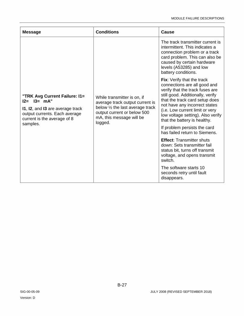
MODULE FAILURE DESCRIPTIONS
B-27 SIG-00-05-09 JULY 2008 (REVISED SEPTEMBER 2018)
Version: D
Message Conditions Cause
"TRK Avg Current Failure: I1= I2= I3= mA" I1, I2, and I3 are average track output currents. Each average current is the average of 8 samples.
While transmitter is on, if average track output current is below ½ the last average track output current or below 500 mA, this message will be logged.
The track transmitter current is intermittent. This indicates a connection problem or a track card problem. This can also be caused by certain hardware levels (A53285) and low battery conditions.
Fix: Verify that the track connections are all good and verify that the track fuses are still good. Additionally, verify that the track card setup does not have any incorrect states (i.e. Low current limit or very low voltage setting). Also verify that the battery is healthy.
If problem persists the card has failed return to Siemens.
Effect: Transmitter shuts down: Sets transmitter fail status bit, turns off transmit voltage, and opens transmit switch.
The software starts 10 seconds retry until fault disappears.
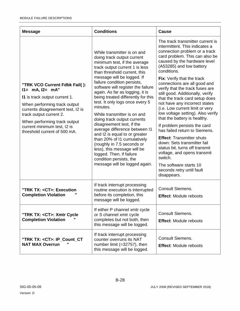
MODULE FAILURE DESCRIPTIONS
B-28 SIG-00-05-09 JULY 2008 (REVISED SEPTEMBER 2018)
Version: D
Message Conditions Cause
"TRK VCO Current Fdbk Fail( ): I1= mA, I2= mA" I1 is track output current 1.
When performing track output currents disagreement test, I2 is track output current 2.
When performing track output current minimum test, I2 is threshold current of 500 mA.
While transmitter is on and doing track output current minimum test, if the average track output current 1 is less than threshold current, this message will be logged. If failure condition persists, software will register the failure again. As far as logging, it is being treated differently for this test. It only logs once every 5 minutes.
While transmitter is on and doing track output currents disagreement test, if the average difference between I1 and I2 is equal to or greater than 20% of I1 cumulatively (roughly in 7.5 seconds or less), this message will be logged. Then, if failure condition persists, the message will be logged again.
The track transmitter current is intermittent. This indicates a connection problem or a track card problem. This can also be caused by the hardware level (A53285) and low battery conditions.
Fix: Verify that the track connections are all good and verify that the track fuses are still good. Additionally, verify that the track card setup does not have any incorrect states (i.e. Low current limit or very low voltage setting). Also verify that the battery is healthy.
If problem persists the card has failed return to Siemens.
Effect: Transmitter shuts down: Sets transmitter fail status bit, turns off transmit voltage, and opens transmit switch.
The software starts 10 seconds retry until fault disappears.
"TRK TX: <CT>: Execution Completion Violation "
If track interrupt processing routine execution is interrupted before its completion, this message will be logged.
Consult Siemens.
Effect: Module reboots
"TRK TX: <CT>: Xmtr Cycle Completion Violation "
If either P channel xmtr cycle or S channel xmtr cycle completes but not both, then this message will be logged.
Consult Siemens.
Effect: Module reboots
"TRK TX: <CT>: IP_Count_CT NAT MAX Overrun "
If track interrupt processing counter overruns its NAT number limit (=32757), then this message will be logged.
Consult Siemens.
Effect: Module reboots

MODULE FAILURE DESCRIPTIONS
B-29 SIG-00-05-09 JULY 2008 (REVISED SEPTEMBER 2018)
Version: D
Message Conditions Cause
"TRK TX: <CT>: IP_Count_CT Cycle Count Overrun "
If track interrupt processing counter overruns its type definition limit (=750), then this message will be logged.
Consult Siemens.
Effect: Module reboots
"Safetran Error: 44 - TRACK Transmitter On Failure "
While transmitter is off and transmitter switch is open, if requested transmitter voltage is greater than 800 mV, this message will be logged.
This error occurs in the internal CPU core area with the output of the DAC which drives the transmitter voltage. This error should never occur or be very rare. A frequent occurrence of this error means that the card has failed. Return it to Siemens.
Effect: Module reboots
"Safetran Error: 62 - TRACK Transmitter Switch Failure"
Near the end of every transmit cycle, a test pulse is generated with transmit switch open. If the average current is greater than 600 mA, this message is logged.
The transmitter switch appears to be shorted.
Fix: If the error is frequent send the card back to Siemens. If this error is a one time event keep the card in service.
Effect: Module reboots.
"TRK Cfg: Illegal Change or Shunt Cycles , , , " First parameter is vital change cycles and legal range is 1 to 3.
Second parameter is non-vital change cycles and legal range is 1 to 3.
Third parameter is shunt pick cycles and legal range is 1 to 8.
Fourth parameter is shunt drop cycles and legal range is 1 to 8.
If any parameter is over the legal range, this message will be logged.
Consult Siemens
Effect: Use default values:
Vital change cycles is 2.
Non-vital change cycles is 1.
Shunt pick cycles is 1.
Shunt drop cycles is 1.
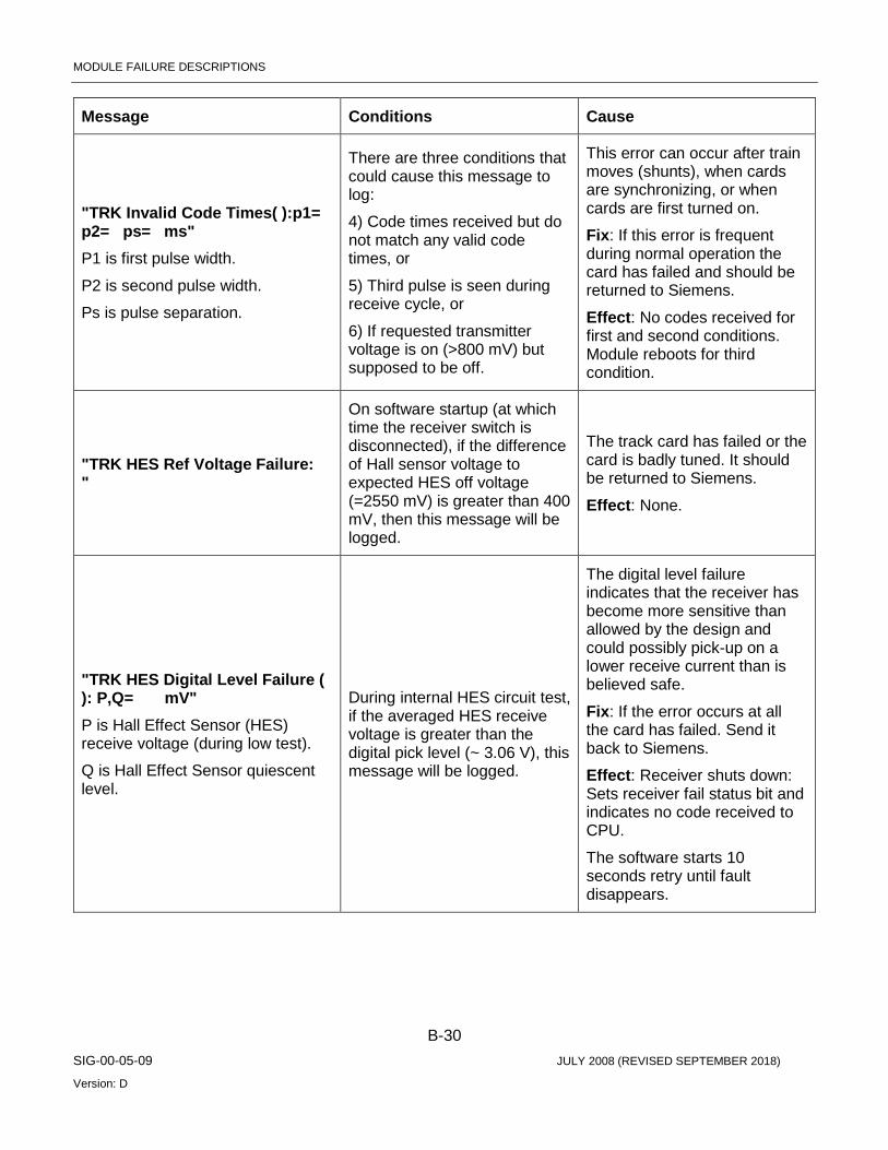
MODULE FAILURE DESCRIPTIONS
B-30 SIG-00-05-09 JULY 2008 (REVISED SEPTEMBER 2018)
Version: D
Message Conditions Cause
"TRK Invalid Code Times( ):p1= p2= ps= ms" P1 is first pulse width.
P2 is second pulse width.
Ps is pulse separation.
There are three conditions that could cause this message to log:
4) Code times received but do not match any valid code times, or
5) Third pulse is seen during receive cycle, or
6) If requested transmitter voltage is on (>800 mV) but supposed to be off.
This error can occur after train moves (shunts), when cards are synchronizing, or when cards are first turned on.
Fix: If this error is frequent during normal operation the card has failed and should be returned to Siemens.
Effect: No codes received for first and second conditions. Module reboots for third condition.
"TRK HES Ref Voltage Failure: "
On software startup (at which time the receiver switch is disconnected), if the difference of Hall sensor voltage to expected HES off voltage (=2550 mV) is greater than 400 mV, then this message will be logged.
The track card has failed or the card is badly tuned. It should be returned to Siemens.
Effect: None.
"TRK HES Digital Level Failure ( ): P,Q= mV" P is Hall Effect Sensor (HES) receive voltage (during low test).
Q is Hall Effect Sensor quiescent level.
During internal HES circuit test, if the averaged HES receive voltage is greater than the digital pick level (~ 3.06 V), this message will be logged.
The digital level failure indicates that the receiver has become more sensitive than allowed by the design and could possibly pick-up on a lower receive current than is believed safe.
Fix: If the error occurs at all the card has failed. Send it back to Siemens.
Effect: Receiver shuts down: Sets receiver fail status bit and indicates no code received to CPU.
The software starts 10 seconds retry until fault disappears.
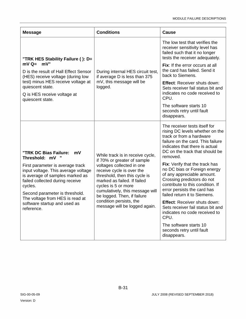
MODULE FAILURE DESCRIPTIONS
B-31 SIG-00-05-09 JULY 2008 (REVISED SEPTEMBER 2018)
Version: D
Message Conditions Cause
"TRK HES Stability Failure ( ): D= mV Q= mV" D is the result of Hall Effect Sensor (HES) receive voltage (during low test) minus HES receive voltage at quiescent state.
Q is HES receive voltage at quiescent state.
During internal HES circuit test, if average D is less than 375 mV, this message will be logged.
The low test that verifies the receiver sensitivity level has failed such that it no longer tests the receiver adequately.
Fix: If the error occurs at all the card has failed. Send it back to Siemens.
Effect: Receiver shuts down: Sets receiver fail status bit and indicates no code received to CPU.
The software starts 10 seconds retry until fault disappears.
"TRK DC Bias Failure: mV Threshold: mV " First parameter is average track input voltage. This average voltage is average of samples marked as failed collected during receive cycles.
Second parameter is threshold. The voltage from HES is read at software startup and used as reference.
While track is in receive cycle, if 70% or greater of sample voltages collected in one receive cycle is over the threshold, then this cycle is marked as failed. If failed cycles is 5 or more cumulatively, this message will be logged. Then, if failure condition persists, the message will be logged again.
The receiver tests itself for rising DC levels whether on the track or from a hardware failure on the card. This failure indicates that there is actual DC on the track that should be removed.
Fix: Verify that the track has no DC bias or Foreign energy of any appreciable amount. Crossing predictors do not contribute to this condition. If error persists the card has failed return it to Siemens.
Effect: Receiver shuts down: Sets receiver fail status bit and indicates no code received to CPU.
The software starts 10 seconds retry until fault disappears.

MODULE FAILURE DESCRIPTIONS
B-32 SIG-00-05-09 JULY 2008 (REVISED SEPTEMBER 2018)
Version: D
Message Conditions Cause
"TRK RX : HES Ref Voltage : Ex = " First parameter is the HES receive voltage read at software startup.
Second parameter is the expected HES receive voltage of 2500 mV.
On software startup, if the HES receive voltage at quiescent state is not within the range of 2500 to 2700 mV, this message will be logged.
There is no known cause for the receiver to be greater than 2700mv. This is probably a hardware failure. On the low side the gray filter and/or a train shunt have been known to decrease the hall sensor voltage below 2500 mV.
The HES voltage reference is set to 0 mV if the HES receive voltage is above 2700 mV. When this voltage reference is used for DC Bias Test, the test will fail and shuts down receiver.
"TRK RX Failure: TRK ( ): Rcvr_Get_Status - Code_Present "
Dual channel software disagreement on Code Present status.
Consult Siemens.
Effect: Module reboots
"TRK RX Failure: TRK ( ): Rcvr_Get_Status - Vtl_Code_Pre"
Dual channel software disagreement on Vital Code Present status.
Consult Siemens.
Effect: Module reboots
"TRK RX Failure: TRK ( ): Rcvr_Get_Status - Track_Code"
Dual channel software disagreement on Track Code status.
Consult Siemens.
Effect: Module reboots
"TRK RX: <CT>: Rcvr Cycle Completion Violation "
If either P channel rcvr cycle or S channel rcvr cycle completes but not both, then this message will be logged.
Consult Siemens.
Effect: Module reboots
"TRK VRO Illegal Commanded ( ) "
If attempt to command other than de-energized state to track card with no VRO hardware component, this message will be logged.
Wrong HW revision. Replace with a track card that has a VRO component.
Effect: None (no VRO functionality is available).
" Safetran Error: 63 - TRK Dual Channel Mismatch "
If the TX/RX cycle and cycle count status disagrees between P and S channel (software channel), this message will be logged.
Consult Siemens.
Effect: Module reboots

MODULE FAILURE DESCRIPTIONS
B-33 SIG-00-05-09 JULY 2008 (REVISED SEPTEMBER 2018)
Version: D
Message Conditions Cause
"VRO Channel Failed, Code: ,Counts: " First parameter is failed VRO channel.
Second parameter is error codes:
1 => SELF_CHECK_FAIL
2 => CHECK_PERIOD_TEST_FAIL
3 => START_UP_CHECK_STATE_FAIL
4 => PARTIAL_CHECK_PERIOD_FAIL
5 => OFF_STATE_FAIL
6 => ON_STATE_FAIL
Third parameter is actual samples count.
Fourth parameter is software channel that detects this failure and is equal to 1 for P channel or 2 for S channel.
This message will be logged with:
Error code 1 – during performing self test, if number of test samples of de-energized state is less than expected test samples (= 1).
Error code 2 – when a complete 1/2 period of a code rate has been seen and that the actual count is not within the acceptable range for the code rate generated.
Error code 3 – to check that VRO is commanded from off to on/coded or from on/coded/coded to coded/on/coded respectively within specified time (third parameter is schedule count).
Error code 4 – when part way through a code rate cycle, if the actual count has exceeded the acceptable maximum for the code rate generated.
Error code 5 – to check that de-energized VROs are still de-energized. If VRO appears flashing or on (set third parameter to 0 if flashing and to actual count if on).
Error code 6 – to check that energized VROs are still energized. If VRO appears flashing or off (set third parameter to 0 if flashing and to actual count if off).
Check to see if the output is shorted out. Otherwise replace the card.
Effect: Set VRO status to failed, turn off failed VRO, and open failed VRO output switch.
The software starts 5 seconds retry until fault disappears.
"Safetran Error: 31 - VRO cycle time "
If the software does not read and empty the VRO’s samples buffer when it is scheduled to, this message will be logged.
The card has failed. Replace the card.
Effect: Module reboots.

MODULE FAILURE DESCRIPTIONS
B-34 SIG-00-05-09 JULY 2008 (REVISED SEPTEMBER 2018)
Version: D
Message Conditions Cause
"Safetran Error: 32 - VRO P/S Mismatch channel " Channel is VRO channel that is seeing the mismatch.
If the VRO output status disagrees between P and S channel (software channel), this message will be logged.
Consult Siemens.
Effect: Module reboots
"Safetran Error: 33 - VRO fail channel " Channel is failed VRO channel.
This test is to check that failed VRO are still de-energized. If the VRO appears flashing or on, this message is logged.
The card has failed. Replace the card.
Effect: Module Reboots.