genesis™ ii - smith+nephew...sizing guide procedure: posterior referencing to use the sizing guide...
TRANSCRIPT

Distal Cut First Surgical Technique
GENESIS™ IITotal Knee System
www.syncera.com

The following technique guide was prepared under the guidance of Consulting Clinicians under close collaboration with each physician. It contains a summary of medical techniques and opinions based upon their training and expertise in the field, along with their knowledge of Smith & Nephew products. It is provided for educational and informational purposes only. Smith & Nephew does not provide medical advice and it is not intended to serve as such. It is the responsibility of the treating physician to determine and utilize the appropriate products and techniques according to their own clinical judgment for each of their patients. For more information on the products in this surgical technique, including indications for use, contraindications, effects, precautions and warnings, please consult the products' Instructions for Use (IFU).
Indications: The Genesis II XLPE Resurfacing Patellar Components are intended to be used with Smith & Nephew Total Knee Systems and their cleared Indications for Use.
Indications for Total Knee Replacementl. Rheumatoid arthritis.
2. Post-traumatic arthritis, osteoarthritis, or degenerative arthritis.
3. Failed osteotomies, unicompartmental replacement, or total knee replacement.
4. Posterior stabilized knee systems are designed for use in patients in primary and revision surgery, where the anterior and posterior cruciate ligaments are incompetent and the collateral ligaments remain intact.
5. Constrained knee systems are designed for use in patients in primary and revision surgery, where the posterior cruciate ligament and one or both of the collateral ligaments (i.e. medial collateral and/or lateral collateral ligament) are incompetent.
6. Hinge knee systems are designed for use in patients in primary and revision surgery, where the posterior cruciate ligament and one or both of the collateral ligaments (i.e. medial collateral and/or lateral collateral ligament) are absent or incompetent.

1
ABOUT SYNCERA™Syncera is a new approach to the purchase and management of primary reconstructive hip and knee implants that have demonstrated long-term survivorship.
Uniquely designed for patients, facilities, surgeons and systems, Syncera provides a solution that enables an empowering, value-driven approach to the acquisition and ongoing management of hip and knee implants.
By combining the proven performance of Smith & Nephew products with cost efficiencies that align surgeons and administrators, you achieve the quality outcomes, improved operational efficiencies and financial impact to excel in today’s environment.
INTRODUCTIONThe GENESIS™ II Total Knee System has been designed to offer the orthopaedic surgeon solutions to address intraoperative situations. Implant function is directly related to accurate surgical technique.
GENESIS II instrumentation has been developed to be an easy-to-use system that will assist the surgeon in obtaining accurate and reproducible knee alignment.
The instrumentation can be used in minimally invasive or standard exposures. While it has been the designers’ objective to develop accurate, easy-to-use instrumentation, each surgeon must evaluate the appropriateness of the following technique based on his or her medical training, experience and patient evaluation.
CONTRIBUTING CLINICIANS Robert B. Bourne, MD, FRCSC Chief of Orthopaedic Surgery University Hospital The University of Western Ontario London, Ontario, Canada
Steven B. Haas, MD, MPH Associate Professor of Orthopaedic Surgery Weill Medical College of Cornell University Associate Chief of the Knee Service The Hospital for Special Surgery New York, New York
Richard S. Laskin, MD Professor of Orthopaedic Surgery Weill Medical College of Cornell University Co-Chief, Knee Service The Hospital for Special Surgery New York, New York
Michael D. Ries, MD Professor and Vice Chairman University of California, San Francisco Department of Orthopaedic Surgery San Francisco, CA
William B. Smith, MD Assistant Clinical Professor in Orthopaedic Surgery Medical College of Wisconsin Columbia Hospital Milwaukee, Wisconsin
Mark A. Snyder, MD Clinical Instructor University of Cincinnati Orthopaedic Surgeon Christ Hospital Cincinnati, Ohio
Todd V. Swanson, MD Desert Orthopaedic Center Las Vegas, Nevada
Jan Victor, MD Department of Orthopaedics St. Lucas Hospital Brugge, Belgium
Nota Bene: The technique description herein is made available to the healthcare professional to illustrate the authors’ suggested treatment for the uncomplicated procedure. In the final analysis, the preferred treatment is that which addresses the needs of the patient.

2
Femoral preparation
Use the 9.5 mm drill to open up the femoral canal and slide the valgus alignment assembly until at least one side contacts the distal femur.
After the assembly is placed in neutral rotation, impact the floating spikes into the distal femur and secure the distal block with pins.
Remove the IM rod, unlock the lever on the valgus alignment guide and remove the valgus alignment assembly using the universal extractor.
Resect the distal femur.
Position the sizing guide flush against the distal femur, while ensuring that the posterior paddles are contacting the underside of both posterior condyles.
To posterior reference, drill and insert two pins through the holes of the sizing guide to secure the guide and prepare holes for the A-P cutting block.
Position the sizing guide stylus so that it contacts the lateral ridge of the anterior cortex and determine the size from the graduations on the shaft of the stylus. If the femur is in-between sizes, choose the larger size.
Optional
To anterior reference, position the sizing guide stylus so that it contacts the lateral ridge of the anterior cortex and determine the size from the graduations on the shaft of the stylus.
If the indicated size is in-between sizes, turn the lower hex screw to raise the anterior surface to the next smaller size. Once the appropriate size is selected, turn the upper hex screw to lock in position. Drill to mark the location holes for the A-P cutting block.
Place the correctly sized A-P cutting block on the distal femur and make anterior, posterior and chamfer cuts.
DISTAL CUT FIRST SHORT TECHNIQUE

3
Tibial preparation
Extramedullary tibial alignment: Assemble extramedullary tibial guide with the non-spiked rod and place on tibia. Align guide over medial third of the tibial tubercle and parallel to the tibia.
Attach the tibial stylus to the tibial cutting block and lower the cutting block until the stylus touches the low point on the least affected side of the tibia. Once the resection level is determined, insert pins to secure and remove alignment assembly.
Resect the proximal tibia.
Size the tibia.
Posterior stabilized
Attach the PS collet to the PS housing block by tightening the gold thumb screw, then pin to the distal femur.
Ream through the collet until the depth stop contacts the collet and then move reamer anterior and posterior until it contacts the depth stops.
Impact the housing box chisel anteriorly and posteriorly through the housing resection collet to square the corners of the housing.
Final preparation
Prepare the patella using surgeon’s preferred technique.
After trial ROM and alignment checks, select the appropriate trial fin punch and punch through the trial.
Seat the tibial implant with the tibial impactor.
Place the femoral implant on the femur and use the femoral impactor to fully seat the implant.
Place the patellar implant onto the patella and clamp onto the bone to pressurize.
Attach the articular inserter/extractor to the tibial tray and engage the insert implant into the locking mechanism.

4
PREOP PLANNING
Determine the angle between the anatomical and the mechanical axes. This measurement will be used intraoperatively to select the appropriate valgus angle so that correct limb alignment is restored. (Beware of misleading angles in knees with a flexion contracture or rotated lower extremities).
Tip: Many surgeons prefer to simply select a standard angle for the distal femoral cut (i.e., 5º, 6º or 7º) based on the patient and surgical experience.
M = Mechanical Axis A = Anatomical Axis
T = Transverse Axis V = Vertical Axis
3º
M M AV
3º
6º
3º3º
T

5
FEMORAL PREPARATION
Intramedullary femoral alignment 1. Open the femoral canal with a 9.5 mm intramedullary drill (Figure 1).
Instrument assembly: a. Attach the selected valgus angle bushing (5°, 6° or 7°) to the valgus
alignment guide. Check the bushing position to make sure that “left” is facing anteriorly (up) when operating on a left knee and “right” is facing anteriorly (up) when operating on a right knee.
b. Attach a modular T-handle to the IM rod and insert through the alignment assembly (Figure 2).
c. Assemble the distal femoral cutting block onto the valgus alignment guide. Positioning the block at the “primary” resection level will ensure the cut will equal the distal thickness of the femoral prosthesis. Lock by pressing the lever in a horizontal position toward the medial side (Figure 3).
Tip: If desired, the distal femoral cutting block may be set to resect an additional +2, +5 or +7 mm of bone.
2. Slide the intramedullary rod of the assembly into the femoral canal until the alignment guide contacts the distal femur (Figure 3).
Tip: It is acceptable for only one side of the guide to touch bone.
3. Orient the rotation of the assembly neutral to the posterior condyles (even amounts of posterior condyles being exposed) (Figure 4) and impact one or both of the floating spikes into the distal femur.
Figure 1
Figure 2
locked
Figure 3
Figure 4

6
Distal femoral resection 1. Using non-headed pins, pin the distal femoral cutting
block to the anterior femur using the holes marked “0.” Once adequate distal femoral resection is verified, an additional headed or non-headed pin may be placed obliquely to provide additional stability (Figure 5).
2. Remove the intramedullary rod. Then, unlock the lever on the valgus alignment guide and remove the valgus alignment assembly using the universal extractor (Figure 6). Only the distal femoral cutting block should remain on the femur.
3. Resect the distal femur (Figure 7), then remove the distal femoral cutting block. If necessary the distal cut may need to be finished without the cutting block in place.
Tip: If the distal femoral resection is not adequate, remove the oblique headed pin, and reposition the block through the pin holes marked +2, +4, or +6 mm for the desired level of resection.
Tip: The ideal thickness of sawblade is 1.35 mm.
Figure 5
unlocked
Figure 6
Figure 7
FEMORAL PREPARATION CONTINUED

7
Femoral sizing guide preparation The sizing guide has drill holes that locate the A-P block (Figure 8). Rotational alignment may also be checked by ensuring that the appropriately angled line on the face of the guide are parallel with the epicondylar axis.
A unique feature of the sizing guide for this system is that it may be used in a traditional posterior referencing or anterior referencing manner. For a full discussion on anterior and posterior referencing, please see Appendix C.
Surgeons wishing to use the sizing guide in an anterior referencing manner should see Appendix C.
(a) anterior surface (b) hex
screws
(c) drill holes
Figure 8

8
Sizing guide procedure: Posterior referencing To use the sizing guide in this manner, the femoral size is read from the graduations on the stylus arm relative to the anterior surface. If the anterior surface is positioned between sizes on the stylus shaft, the larger of the two sizes should be chosen.
1. Place the sizing guide flush against the distal femur, while ensuring the posterior paddles contact the underside of both posterior condyles (Figure 9).
Ensure that the anterior portion of the sizing guide is in the lowest level position.
Tip: It is not necessary that the guide be centered on the femur, as long as the paddles adequately reference both posterior condyles.
2. Drill and insert two pins through the holes of the sizing guide to secure the guide and prepare holes for the A-P cutting block (Figure 10).
3. Insert the sizing guide stylus into the top of the sizing guide and position the stylus so that it contacts the lateral ridge of the anterior femoral cortex (Figure 11).
Tip: There should only be about 1/2" to 3/4" between the edge of the stylus arm and edge of knob.
4. Determine the size of the component from the gradations on the shaft of the stylus, choosing the larger size if in-between sizes.
5. Remove the pins and the sizing guide.
Figure 9
Figure 10
1/2" – 3/4"
Figure 11
FEMORAL PREPARATION CONTINUED

9
A-P femoral resection 1. Position the fixed spikes on the A-P cutting block into the
predrilled holes.
Tip: It is not necessary that the block be centered M-L on the distal femur.
2. Ensure that the cutting block is flush with the resected distal femur. Several holes in the A-P block allow fixation of the block. Place one pin centrally through the middle holes below the quick-connect attachment. For additional stability, a smooth headed pin may be placed through the holes on the medial or lateral side of the block (Figure 12).
3. Complete the anterior, posterior and chamfer cuts (Figures 13-16). The block is designed to allow for angling of the sawblade during the cuts.
Tip: To maintain block stability, the anterior chamfer cut should be completed last.
Tip: Some surgeons prefer to make the chamfer cuts after assuring that the flexion and extension spaces are equal. If desired, chamfer cuts may be made through the posterior stabilized femoral housing block or through dedicated chamfer cutting blocks.
Figure 12
Figure 13
Figure 14
Figure 15
Figure 16

10
Posterior stabilized only step
Instrument assembly and technique: Attach the housing reamer dome and the PS reamer sleeve to the patellar reamer shaft (Figure 17).
1. Attach the PS housing resection collet to the housing resection block by tightening the gold thumbscrew in the most anterior position (which posteriorizes the collet relative to the bone) (Figure 18).
2. The PS housing resection block must be centered on the femur, as this will determine component position.
Tip: The housing resection blocks have the same M-L dimension as the implants.
Tip: The only difference between the cruciate retaining and the Posterior Stabilized femoral components is the addition of the housing for the cam mechanism. All other box dimensions are the same. The anterior and posterior chamfer resections can be made through the Posterior Stabilized housing resection block. .
3. Secure with 1/8” trocar pins through the straight holes in the front of the block. If the chamfer cuts are made through this block, the angled holes in the sides of the block should be used.
4. Ream through the housing resection collet until the automatic depth stop contacts the collet, loosen the thumbscrew and then move the reamer anterior and posterior until it contacts the automatic stop (Figure 19).
5. Impact the housing box chisel through the housing resection collet to square the corners of the housing. The housing box chisel should be used anteriorly and posteriorly to ensure that the full length of the box is prepared (Figure 20).
6. If the chamfer resections have not been made, they can now be made by cutting through the chamfer slots in the housing resection block.
Figure 17
Figure 18
Figure 19
Figure 20

11
Optional step
Downsizing the femoral component1. Attach the downsizing drill guide to the cut femur,
placing the spikes on the back of the plate into the same location holes used for the A-P cutting blocks (Figure 21).
2. Drill new location holes through the block (shifted 2 mm anterior).
3. Place the smaller A-P cutting block into the new location holes. Redo the posterior, anterior and chamfer cuts.
Tip: It is useful to mark the original pin track holes with methylene blue in order to properly identify the new holes. Figure 21

12
TIBIAL PREPARATION
Non-spiked fixation rod1. Place the arms of the extramedullary alignment
clamp around the ankle, and adjust the distal M-L slide directly over the middle of the tibiotalar joint, which is also approximated by the second ray of the foot proximal to the malleoli (Figure 24). The cutting block on the proximal end of the assembly should be proximal to the tibial tubercle (Figure 25).
2. Assess rotation of the alignment guide and slope of the cutting plane. The goal is to align the extramedullary alignment assembly rotationally so that it aligns over the medial third of the tibial tubercle and over the second toe (Figure 26).
3. Rotational alignment is critical due to the 3º posterior sloped cut. The slope can be adjusted according to the patient’s anatomy (Figure 27).
Note: 3-5° of slope is built into the articular insert (depending on which insert is chosen) and 3º of slope is built into the tibial cutting block. A slope in-line with the saggital mechanical axis of the tibia should usually be chosen (Figure 27).
Tip: Neutral or minimally sloped alignment may be achieved by palpating the fibula followed by aligning the alignment guide parallel to the fibula.
Figure 24 Figure 25
Figure 26 Figure 27
EXTRAMEDULLARY TIBIAL ALIGNMENTInstrument assembly: a. Insert the ankle clamp into the distal end of the
alignment tube and thread the locking pin into the ankle clamp (Figure 22).
b. After the ankle clamp is moved into the proper position, lock into place with the gold knob.
c. Choose the correct left or right tibial cutting block.
Instrument assembly: a. Place the appropriate left or right tibial cutting block
on top of the disc on the non-spiked fixation rod (Figure 23). Tighten the central knob to lock the block into position.
b. Introduce the rod into the Extramedullary Assembly and adjust and lock the cam in the assembly (Figure 23).
central knob
locking cam
Figure 22 Figure 23

13
Tibial resection1. Attach the tibial stylus to the tibial cutting block by
inserting the stylus foot into the cutting slot.
2. Lower the cutting block until the stylus touches the low point on the less affected side of the tibia (Figure 28). The stylus can be adjusted for a 9, 11 or 13 mm tibial resection by twisting the knob on top of the stylus.
3. Pin the tibial cutting block to the tibia by inserting pins first through the central holes; then the oblique hole.
Tip: Pinning through the central holes marked 0 mm with smooth pins will allow the block to be moved +2 mm should additional resection be required (Figure 29).
Tip: A 9 mm resection is recommended since 9 mm of metal and plastic is the thinnest available component.
4. To remove the assembly: The extramedullary assembly with the non-spiked rod may be left in place or removed by loosening the thumbscrew and lowering the non-spiked rod to disengage from the tibial cutting block.
Tip: To do an extramedullary alignment check, place the extramedullary alignment rod through the tibial cutting block and tighten the central knob.
5. Cut the tibia by first directing the blade in the posterior direction and then laterally (Figure 30).
6. Check alignment and balance with spacer block and rod (Figures 31 and 32). Balance ligaments in standard fashion.
Tip: Since the spacer block has one end for flexion and one for extension, ensure that the appropriate end is used.
Figure 28 Figure 29
Figure 30
Figure 31 Figure 32
14
TIBIAL SIZING
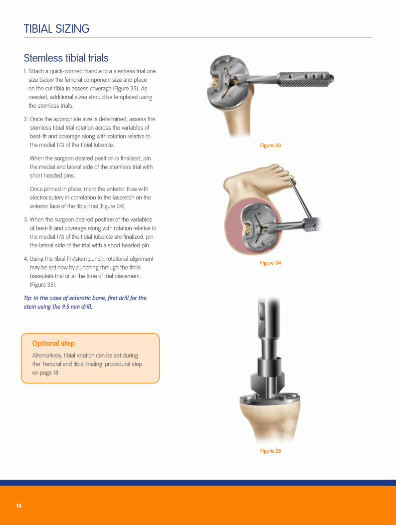
Stemless tibial trials 1. Attach a quick-connect handle to a stemless trial one
size below the femoral component size and place on the cut tibia to assess coverage (Figure 33). As needed, additional sizes should be templated using the stemless trials.
2. Once the appropriate size is determined, assess the stemless tibial trial rotation across the variables of best-fit and coverage along with rotation relative to the medial 1/3 of the tibial tubercle.
When the surgeon desired position is finalized, pin the medial and lateral side of the stemless trial with short headed pins.
Once pinned in place, mark the anterior tibia with electrocautery in correlation to the laseretch on the anterior face of the tibial trial (Figure 34).
3. When the surgeon desired position of the variables of best-fit and coverage along with rotation relative to the medial 1/3 of the tibial tubercle are finalized, pin the lateral side of the trial with a short headed pin.
4. Using the tibial fin/stem punch, rotational alignment may be set now by punching through the tibial baseplate trial or at the time of trial placement. (Figure 35).
Tip: In the case of sclerotic bone, first drill for the stem using the 9.5 mm drill.
Figure 33
Figure 34
Figure 35
Optional step
Alternatively, tibial rotation can be set during the 'Femoral and tibial trialing’ procedural step on page 18.

15
RESURFACING PATELLAR PREPARATION
1. Trim tissue surrounding the patella using electrocautery (bovie) (Figure 36).
2. Use a rongeur to remove osteophytes and reduce the patella to its true size (Figure 37). The bovie should also be used to release soft tissue attachments to the estimated level of resection.
3. Measure patellar thickness with the patellar calipers (Figure 38).
Determine the design and diameter of the patellar implant to be used. A round may be chosen. The round resurfacing patella is 9 mm thick.
4. Resect the patella using the freehand cutting technique with towel-clips and a standard saw with a wide blade.
5. Centralize the thickest portion of the prosthetic patella along the line of the medial facet eminence.
6. Place the appropriate drill guide on the patellar reamer guide and clamp the guide to the patella. Drill to the measured depths (Figure 39).
7. Place the trial on the patella and remeasure the patella if desired (Figure 40).
Figure 36
Figure 37
Figure 38
Figure 40Figure 39

16
Femoral and tibial trialing (CR and PS) 1. Flex the knee to 90° and insert the appropriate femoral trial (CR or PS) using the
femoral trial impactor (Figure 41).
2. Use the appropriate insert trial (CR or PS variant) (beginning with a 9 mm trial and increasing thickness and articulation as needed for desired balance) to determine stability and alignment.
3. Perform a trial range of motion. The alignment marks on the front of the femoral and tibial trials should line up (Figure 42). If rotation was not set earlier during the stemless tibial tray placement step, the quick-connect handle may be attached to the tibial trial and used to set the appropriate tibial rotational alignment (Figure 43). If it was already selected you may skip step 4.
Tip: The technique of tibial trial, then femoral trial and then trial insert works for all GENESIS™ II inserts except the dished inserts. For the deep dished, the trial bearing should be inserted before the femoral trial.
Mark correct tibial rotational alignment on the anterior tibia using a cautery knife (Figure 43).
Figure 42
Figure 43Figure 41

17
4. Select the appropriately sized tibial fin punch to prepare the fins and punch through the tibial trial (Figure 44).
Tip: If the tibial bone is sclerotic, begin the fin slot with a burr or thin sawblade before using the fin punch to prevent tibial fracture.
5. Perform a trial range of motion to assess patellar tracking. With cruciate-retaining knees, medial-lateral placement of the femoral trial can be adjusted to optimize patellar tracking (Figure 45).
6. Remove the tibial trial. Attach the end of the universal extractor to the femoral trial (Figure 47).
Remove the femoral trial. Use a towel clip to remove the patellar trial.
Figure 45
Figure 46
Figure 47
Figure 44
Cruciate retaining only step
For cruciate-retaining femorals, prepare the femoral lug holes through the femoral trial with the femoral lug punch (Figure 46).
18
IMPLANTATION
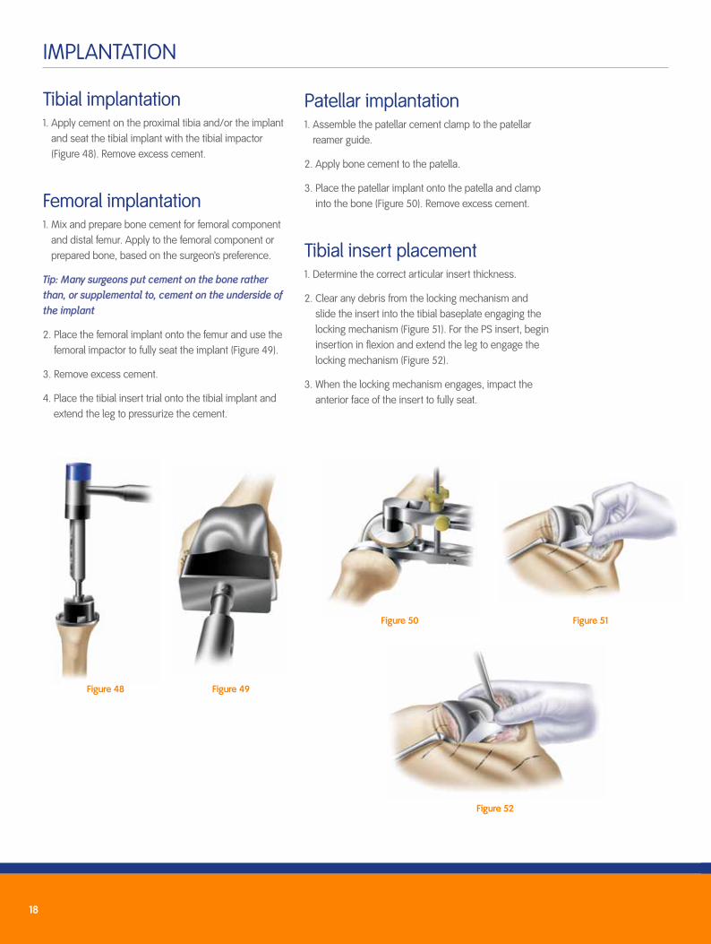
Tibial implantation1. Apply cement on the proximal tibia and/or the implant
and seat the tibial implant with the tibial impactor (Figure 48). Remove excess cement.
Femoral implantation1. Mix and prepare bone cement for femoral component
and distal femur. Apply to the femoral component or prepared bone, based on the surgeon’s preference.
Tip: Many surgeons put cement on the bone rather than, or supplemental to, cement on the underside of the implant
2. Place the femoral implant onto the femur and use the femoral impactor to fully seat the implant (Figure 49).
3. Remove excess cement.
4. Place the tibial insert trial onto the tibial implant and extend the leg to pressurize the cement.
Figure 48 Figure 49
Patellar implantation1. Assemble the patellar cement clamp to the patellar
reamer guide.
2. Apply bone cement to the patella.
3. Place the patellar implant onto the patella and clamp into the bone (Figure 50). Remove excess cement.
Tibial insert placement1. Determine the correct articular insert thickness.
2. Clear any debris from the locking mechanism and slide the insert into the tibial baseplate engaging the locking mechanism (Figure 51). For the PS insert, begin insertion in flexion and extend the leg to engage the locking mechanism (Figure 52).
3. When the locking mechanism engages, impact the anterior face of the insert to fully seat.
Figure 50 Figure 51
Figure 52

19
APPENDIX A: GENESIS™ II ARTICULAR INSERT INTERCHANGEABILITY CHART Cruciate retaining inserts: Completely interchangeable with all size femoral components.
Posterior Stabilized (PS), Dished (DD), Posterior Stabilized High Flexion (PSHF) and Cruciate Retaining Deep Flex (CRDF): Limited interchangeability; chart applies.
Insert Size 1 2 3 4 5 6 7 8 9
1-2 PS, DD • • •1-2 PSHF, CRDF • • • •3-4 PS, DD • • • •3-4 PSHF, CRDF • • • • •5-6 PS, DD • • • •5-6 PSHF, CRDF • • • • •7-8 PS, DD • • •7-8 PSHF, CRDF • • • •
9 11 13 15 18
CR • • • • •PS • • • • •DD • • • • •CRDF • • • •PSHF • • • •Note: Minimum polyethylene thickness for a 9 mm metal backed component is 6.7 mm thick under the condyles.
Articular Insert Interchangeability Cruciate Retaining inserts: Completely interchangeable with all size femoral components.
Posterior-Stabilized (PS), Dished (DD), Posterior-Stabilized High Flexion (PSHF) and
Cruciate Retaining Deep Flex (CRDF): Limited interchangeability; chart applies.
Femoral Size
Insert Size 1 2 3 4 5 6 7 8 9
1-2 PS, DD
1-2 PSHF, CRDF
3-4 PS, DD
3-4 PSHF, CRDF
5-6 PS, DD
5-6 PSHF, CRDF
7-8 PS, DD
7-8 PSHF, CRDF
Articular Insert Thickness
9 11 13 15 18 21 25 30
CR
PS
DD
CRDF
PSHF
Note: Minimum polyethylene thickness for a 9 mm metal backed component is 6.7 mm thick under the condyles.
Average Slope for Articular Inserts
Note: All dimensions include 3° posterior cut and are in millimeters (mm) unless specified otherwise.
7°
7˚
CR DD PSCRDF PSHF
7˚
7˚8˚
6˚
CR
Articular Insert Interchangeability Cruciate Retaining inserts: Completely interchangeable with all size femoral components.
Posterior-Stabilized (PS), Dished (DD), Posterior-Stabilized High Flexion (PSHF) and
Cruciate Retaining Deep Flex (CRDF): Limited interchangeability; chart applies.
Femoral Size
Insert Size 1 2 3 4 5 6 7 8 9
1-2 PS, DD
1-2 PSHF, CRDF
3-4 PS, DD
3-4 PSHF, CRDF
5-6 PS, DD
5-6 PSHF, CRDF
7-8 PS, DD
7-8 PSHF, CRDF
Articular Insert Thickness
9 11 13 15 18 21 25 30
CR
PS
DD
CRDF
PSHF
Note: Minimum polyethylene thickness for a 9 mm metal backed component is 6.7 mm thick under the condyles.
Average Slope for Articular Inserts
Note: All dimensions include 3° posterior cut and are in millimeters (mm) unless specified otherwise.
7°
7˚
CR DD PSCRDF PSHF
7˚
7˚8˚
6˚CRDF
Articular Insert Interchangeability Cruciate Retaining inserts: Completely interchangeable with all size femoral components.
Posterior-Stabilized (PS), Dished (DD), Posterior-Stabilized High Flexion (PSHF) and
Cruciate Retaining Deep Flex (CRDF): Limited interchangeability; chart applies.
Femoral Size
Insert Size 1 2 3 4 5 6 7 8 9
1-2 PS, DD
1-2 PSHF, CRDF
3-4 PS, DD
3-4 PSHF, CRDF
5-6 PS, DD
5-6 PSHF, CRDF
7-8 PS, DD
7-8 PSHF, CRDF
Articular Insert Thickness
9 11 13 15 18 21 25 30
CR
PS
DD
CRDF
PSHF
Note: Minimum polyethylene thickness for a 9 mm metal backed component is 6.7 mm thick under the condyles.
Average Slope for Articular Inserts
Note: All dimensions include 3° posterior cut and are in millimeters (mm) unless specified otherwise.
7°
7˚
CR DD PSCRDF PSHF
7˚
7˚8˚
6˚
PS
Articular Insert Interchangeability Cruciate Retaining inserts: Completely interchangeable with all size femoral components.
Posterior-Stabilized (PS), Dished (DD), Posterior-Stabilized High Flexion (PSHF) and
Cruciate Retaining Deep Flex (CRDF): Limited interchangeability; chart applies.
Femoral Size
Insert Size 1 2 3 4 5 6 7 8 9
1-2 PS, DD
1-2 PSHF, CRDF
3-4 PS, DD
3-4 PSHF, CRDF
5-6 PS, DD
5-6 PSHF, CRDF
7-8 PS, DD
7-8 PSHF, CRDF
Articular Insert Thickness
9 11 13 15 18 21 25 30
CR
PS
DD
CRDF
PSHF
Note: Minimum polyethylene thickness for a 9 mm metal backed component is 6.7 mm thick under the condyles.
Average Slope for Articular Inserts
Note: All dimensions include 3° posterior cut and are in millimeters (mm) unless specified otherwise.
7°
7˚
CR DD PSCRDF PSHF
7˚
7˚8˚
6˚PSHF
Articular Insert Interchangeability Cruciate Retaining inserts: Completely interchangeable with all size femoral components.
Posterior-Stabilized (PS), Dished (DD), Posterior-Stabilized High Flexion (PSHF) and
Cruciate Retaining Deep Flex (CRDF): Limited interchangeability; chart applies.
Femoral Size
Insert Size 1 2 3 4 5 6 7 8 9
1-2 PS, DD
1-2 PSHF, CRDF
3-4 PS, DD
3-4 PSHF, CRDF
5-6 PS, DD
5-6 PSHF, CRDF
7-8 PS, DD
7-8 PSHF, CRDF
Articular Insert Thickness
9 11 13 15 18 21 25 30
CR
PS
DD
CRDF
PSHF
Note: Minimum polyethylene thickness for a 9 mm metal backed component is 6.7 mm thick under the condyles.
Average Slope for Articular Inserts
Note: All dimensions include 3° posterior cut and are in millimeters (mm) unless specified otherwise.
7°
7˚
CR DD PSCRDF PSHF
7˚
7˚8˚
6˚
DD
Articular Insert Interchangeability Cruciate Retaining inserts: Completely interchangeable with all size femoral components.
Posterior-Stabilized (PS), Dished (DD), Posterior-Stabilized High Flexion (PSHF) and
Cruciate Retaining Deep Flex (CRDF): Limited interchangeability; chart applies.
Femoral Size
Insert Size 1 2 3 4 5 6 7 8 9
1-2 PS, DD
1-2 PSHF, CRDF
3-4 PS, DD
3-4 PSHF, CRDF
5-6 PS, DD
5-6 PSHF, CRDF
7-8 PS, DD
7-8 PSHF, CRDF
Articular Insert Thickness
9 11 13 15 18 21 25 30
CR
PS
DD
CRDF
PSHF
Note: Minimum polyethylene thickness for a 9 mm metal backed component is 6.7 mm thick under the condyles.
Average Slope for Articular Inserts
Note: All dimensions include 3° posterior cut and are in millimeters (mm) unless specified otherwise.
7°
7˚
CR DD PSCRDF PSHF
7˚
7˚8˚
6˚
Note: All dimensions include 3° posterior cut and are in millimeters (mm) unless specified otherwise.
Articular insert thickness
Femoral size
Average Slope for articular inserts

20
APPENDIX B: ANTERIOR AND POSTERIOR REFERENCING
Anterior referencingAn anterior referencing technique is based on the anterior cortex, which serves as the primary reference point. The anterior resection is fixed while the posterior resection varies with size. Because the component will be flush against the anterior cortex, this will enable the reapproximation of the patellofemoral joint. When the sizing guide indicates the femoral implant is between two sizes, the smaller size should be selected. Choosing the smaller size results in more bone resection from the posterior condyles thereby increasing the flexion space.
Posterior referencingA posterior referencing technique is based on the posterior femoral condyles which serve as the reference point. The posterior resection remains constant while the anterior resection varies with respect to the anterior cortex.
Therefore, the posterior resection will equal the posterior thickness of the prosthesis, resulting in a balanced flexion-extension space. When the sizing guide indicates the femoral implant is between two sizes, the larger size should be chosen. Even though there is a slight chance in overstuffing the patellofemoral joint with a larger size, there is a reduced risk in notching the anterior cortex of the femur.
Anterior referencing
Advantages Disadvantages
Reapproximation of the patellofemoral joint
Knee may be loose in flexion
Reduced chance of notching the anterior cortex
Posterior referencing
Advantages Disadvantages
Balanced flexion and extension spaces
May overstuff the patellofemoral joint

To use the sizing guide in this manner, femoral size is read from the graduations on the stylus arm relative to the anterior surface.
If the anterior surface of the guide is in-between two sizes when it is in the lowest position, the lower hex screw mechanism can be rotated to shift both the anterior surface and the drill holes up to the next smaller size on the stylus (Figures 53a and 53b). As a result, the anterior surface and associated drill holes are shifted anteriorly to align with the next smaller implant size.
Tip: The gap between the anterior surface and the stylus graduation line indicating the smaller size is how much additional bone will be removed from the posterior condyles by choosing the smaller size (Figure 53c).
1. Place the sizing guide flush against the distal femur, while ensuring the posterior paddles contact the underside of both posterior condyles. Ensure that the anterior portion of the sizing guide is in the lowest level position.
Tip: It is not necessary that the guide be centered on the femur, as long as the paddles adequately reference both posterior condyles.
2. Position the sizing guide stylus so that it contacts the lateral ridge of the anterior femoral cortex where the anterior flange will end (Figure 54).
Tip: There should only be about 1/2" to 3/4" between the edge of the stylus arm and edge of knob.
3. Determine the size of the component from the graduations on the shaft of the stylus (Figure 55).
4. If in-between sizes, turn the lower hex screw to raise the anterior surface to the next smaller size (Figures 53a, 53b, 53c and 56). Once the appropriate size is selected, turn the upper hex screw to lock the anterior surface and drill holes in position.
5. Drill the holes to mark the location holes for the A-P cutting block and then remove the sizing guide.
Figure 53c
Figure 53a Figure 53b
APPENDIX C: SIZING GUIDE PROCEDURE – ANTERIOR REFERENCING
1/2”3/4”
Figure 56
Figure 55
Figure 54

Smith & Nephew, Inc.7135 Goodlett Farms ParkwayCordova, TN 38016USA
™ Trademark of Smith & Nephew. Certain marks Registered US Patent and Trademark Office. All Trademarks acknowledged. ©2016 Smith & Nephew. All rights reserved. Printed in USA. 02587 V2 07/16
www.syncera.com 800-248-4668 800-383-0047 fax