generic eps model - ipg automotive gmbh · generic eps model adam opel ag, control systems &...
TRANSCRIPT


www.opel.com
Generic Modeling and Control of an Electromechanical
Power Steering System for Virtual Prototypes
GENERIC EPS MODEL
Adam Opel AG, Control Systems & Brake CAE
Karlsruhe, Apply & Innovate, 20 September 2016
Dipl.-Ing. Roman Mannale,
Volker Ewald, Dr.-Ing. Markus Bauer
1. Introduction
2. EPS tool chain
3. Generic EPS model
4. Summary
AGENDA
3

VARIANT DIVERSITY
4
0
50
100
150
200
250
300
350
400
450
Senator
Astra
ABS, ESC, AWD, CDC
ABS & ESC
Chassis & ADAS
ABS
1984 1994 2004 2014
Increasing development, tuning and validation effort
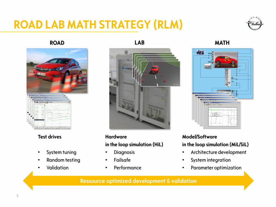
ROAD LAB MATH STRATEGY (RLM)
5
Model/Software
in the loop simulation (MiL/SiL)
• Architecture development
• System integration
• Parameter optimization
Hardware
in the loop simulation (HiL)
• Diagnosis
• Failsafe
• Performance
LAB
Test drives
• System tuning
• Random testing
• Validation
ROAD
Ressource optimized development & validation
MATH
11
11
11
11
00
1/z
1/z
1/z
11
Straßenanregung MatCarAdam Opel AG
? ? ?
Manöver
IVCSIVCS
[BLS]
[man_mcp]man_mcp
[gas_gear_clutch]gas_gear_clutch
[stwhl_ang]stwhl_ang
1EngRngSt_value1
ESP / ABS / TCS
Demux
CDC

Control Systems Master Model (CSMM)
Multi Body Simulation (MBS)Master Model
SIMULATION TOOL CHAIN OVERVIEW
6
AxleFull vehicle
SiL
HiL
DiL
CarMaker (CM)vehicle infofiles
ComponentDatabase
ASCII
(CM-Infofile)
Parameters
ComponentData
Measurements
Design Data CSMM
Component Models CM-Models
Simulink Models
S-functions
c-Code
© fkfs.de

MASTER MODEL APPROACH
7User 1 User 2 User n
Master Model Master Model Master Model
Library 1
Library m

RLM EXAMPLES
8
Architecture phase Prototype phase Tuning & Validation
Develop Test
MiL SiL
HiL
Vehicle ROAD
LAB
MATH
Mule
Elimination
ESC
Homologation
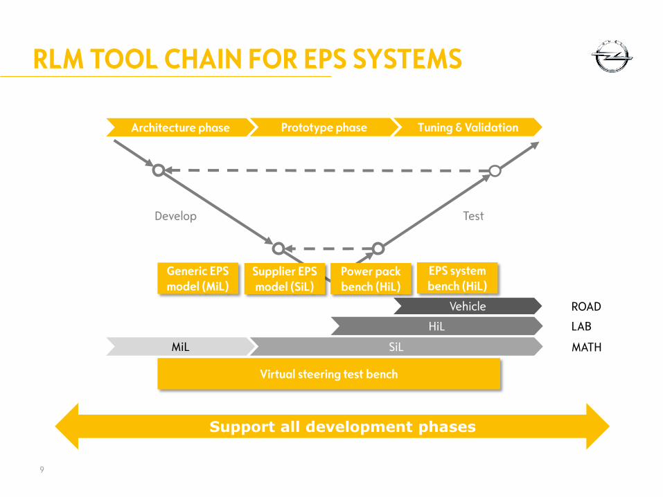
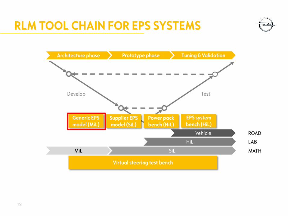
RLM TOOL CHAIN FOR EPS SYSTEMS
9
Support all development phases
Develop Test
Architecture phase Prototype phase Tuning & Validation
MiL SiL
HiL
Vehicle ROAD
LAB
MATH
Generic EPS
model (MiL)
Supplier EPS
model (SiL)
Power pack
bench (HiL)
EPS system
bench (HiL)
Virtual steering test bench
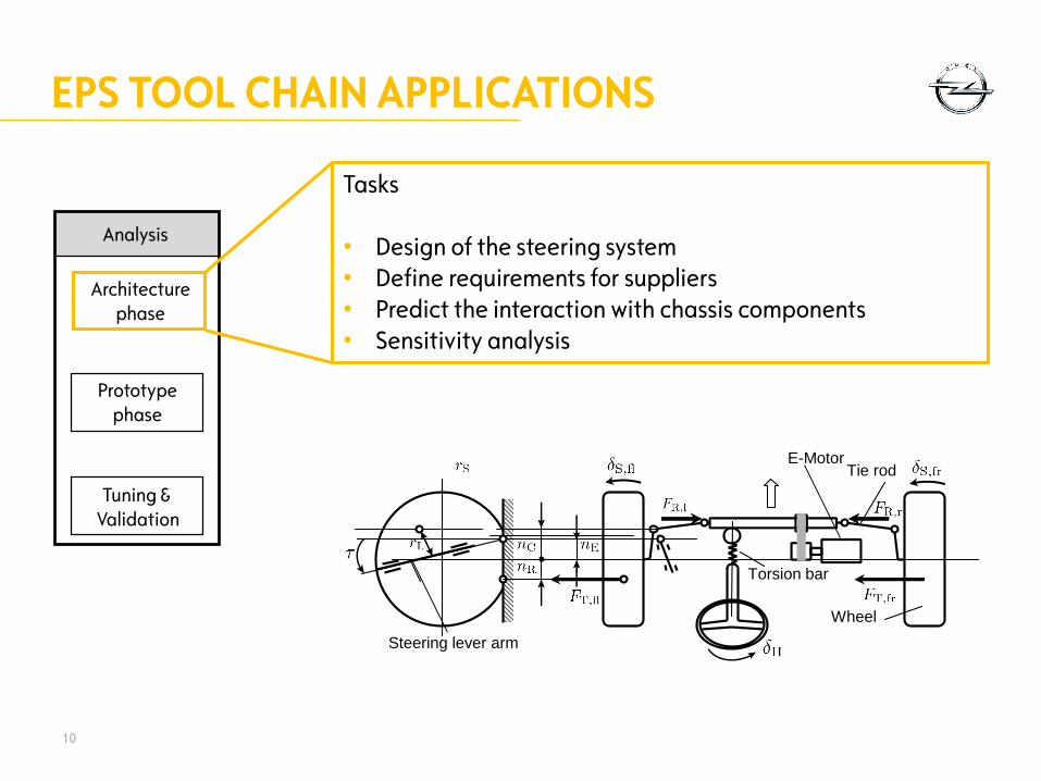
EPS TOOL CHAIN APPLICATIONS
10
Analysis
Architecture
phase
Prototype
phase
Tuning &
Validation
Steering lever arm
Wheel
Tie rod
Torsion bar
E-Motor
Tasks
• Design of the steering system
• Define requirements for suppliers
• Predict the interaction with chassis components
• Sensitivity analysis

EPS TOOL CHAIN APPLICATIONS
11
Analysis
Tuning &
Validation
Tasks
• Detailed analysis of the interaction with chassis components
Dampers
Bushes
Mounting …
• ECU functional testing
Architecture
phase
Prototype
phase

EPS TOOL CHAIN APPLICATIONS
12
Analysis
Tuning &
Validation
Tasks
• ECU testing
Functional testing
Performance testing according to internal spec.
Pre-calibration of control functions
Architecture
phase
Prototype
phase
Power pack
bench (HiL)
EPS system
bench (HiL)

RLM TOOL CHAIN FOR EPS SYSTEMS
13
Develop Test
Architecture phase Prototype phase Tuning & Validation
MiL SiL
HiL
Vehicle ROAD
LAB
MATH
Generic EPS
model (MiL)
Supplier EPS
model (SiL)
Power pack
bench (HiL)
EPS system
bench (HiL)
Virtual steering test bench

VIRTUAL STEERING TEST BENCH
14
Automatic
identification
Model parameters
Measurement data
(from MBS or real system)
Validation
Validated
steering model
Measurement data
(from MBS or real system),
steering model
Analysis
Controlability, observability,
modal/stability/sensitivity analysis
Steering model
Virtual steering
test bench
EPS model B
EPS model AEPS model C
EPS model D
One tool for all models
(Opel/Supplier)
RLM TOOL CHAIN FOR EPS SYSTEMS
15
Develop Test
Architecture phase Prototype phase Tuning & Validation
MiL SiL
HiL
Vehicle ROAD
LAB
MATH
Generic EPS
model (MiL)
Supplier EPS
model (SiL)
Power pack
bench (HiL)
EPS system
bench (HiL)
Virtual steering test bench

GENERIC EPS MODEL COMPONENTS
• Controller model
• Reference model for target behaviour
• Model based approach: Internal Model Control
• Motor model
• Mechanical steering model
16
Non-linear
friction
Non-linear
friction
2 degrees
of freedom

REQUIREMENTS FOR GENERIC EPS MODEL
• Model in the loop Available for early development
• Modular concept
• Cover all basic EPS functions
• Physically-based self-adjusting controller setup
17
Generic EPS
model
Vehicle parametersEPS target values

18
F(s) GR(s)
GM(s)
-
u
yd
d
Filter Controller System
Model
Disturbances
Model error
G (s)
GR(s) = 1/GM(s)
INTERNAL MODEL CONTROL APPROACH
Controller parameters reflect physical parameters of the system
-

GENERIC EPS MODEL OVERVIEW
19
Generate reference
intermediate shaft
angular speed
Steering wheel
torque
Observers
Friction
compensator
Model (IMC)
Disturbance
compensator
Controller
(IMC)
Mech. system

GENERIC EPS REFERENCE GENERATION
20
Reference
intermediate shaft
angular speed
Steering wheel
torque
Stationary model
- Define desired
steering support (Boost Curve)
Dynamic model
- Ideal dynamic reference behaviour
- Tunable damping

GENERIC EPS EXAMPLE RESULT
• Test run:
• 100 km/h
• Slowly increase steering wheel angle (quasi stationary)
• Two vehicle models:
• Middle class
• Compact class
21
Lateral vehicle acceleration
Steering
wheel
torque
Middle class
Target behaviour
Compact class
Two vehicles classes, similar
steering wheel torque

SUMMARY
• RLM strategy for ressource optimized development & validation• Model/software in the loop (Math)
• Hardware in the loop (Lab)
• Test drives (Road)
• EPS tool chain as one part of RLM covers all development phases• Architecture phase
• Prototype phase
• Tuning & Validation
• Generic EPS model allows early analysis & system understanding • Available for early development (MiL)
• Modular concept
• Covers all basic EPS functions
• Physically-based self-adjusting controller setup
22

Roman Mannale
THANK YOU