generic design assessment - westinghouse ap1000 ... and safety executive . nuclear directorate ....
TRANSCRIPT

Health and Safety Executive
NUCLEAR DIRECTORATE
GENERIC DESIGN ASSESSMENT – NEW CIVIL REACTOR BUILD
STEP 3 PROBABILISTIC SAFETY ANALYSIS OF THE WESTINGHOUSE AP1000
DIVISION 6 ASSESSMENT REPORT NO. AR 09/017-P
HSE Nuclear Directorate Redgrave Court Merton Road Bootle Merseyside L20 7HS

HSE Nuclear Directorate Division 6 Assessment Report No. AR 09/017-P
Page (i)
EXECUTIVE SUMMARY
This report provides an overview of the Nuclear Directorate’s (ND) Generic Design Assessment (GDA) Step 3 assessment of the AP1000 Probabilistic Safety Analysis (PSA) presented in report UK AP1000 Probabilistic Risk Assessment (UKP-GW-GL-022, Rev 0) provided by Westinghouse in support of the AP1000 European Design Control Document (EPS-GW-GL-700, Rev 0). For GDA Step 3 it is important to note that the PSA has not been assessed in its entirety; rather, the arguments that support high level claims (which were assessed in Step 2) on how the PSA related Safety Assessment Principles are met, have been looked at. The evidence supporting these claims and arguments will be examined in Step 4. For PSA, ‘arguments’ are interpreted as being the methods, techniques and scope of the PSA. The assessment conducted during GDA Step 3 has mainly been restricted to those areas but some in-depth spot checks of models and data have also been conducted to gather information on how those methods and techniques have been applied by Westinghouse. The AP1000 PSA is a Level 1 and Level 2 PSA. A Level 3 PSA has been performed but it has not been reviewed during GDA Step 3. The scope of the PSA includes consideration of internal initiated events and internal hazards and includes low power and shutdown operating states. The methods and data used in the PSA are well known, although not always up-to-date or aligned with the latest international good practices. During GDA Step 3 a high level review of all the PSA technical areas against the tables contained in Annex 1 of Nuclear Directorate’s PSA guide (T/AST/030 Issue 3, February 2009) has been conducted. In addition, a detailed review of the PSA Task on “identification and grouping of internal initiating events during operation at power” has been also done to confirm whether the basis of the PSA are robust and to gain confidence on its completeness. The GDA Step 3 review has been undertaken with the assistance of Technical Support Contractors who have carried out their work under direction and supervision of ND. From the GDA Step 3 review carried out, 85 Technical Queries (TQ) and 2 Regulatory Observations (RO) have been issued. An ‘AP1000 PSA Step 3 Assessment Wrap-up Meeting’ was held in August 2009 with representatives from ND’s GDA team (including TSCs), Westinghouse and some Utilities to agree the priority of each TQ and RO. The current PSA with its current scope provides part of the basis to interpret the risk associated with this reactor and where the main design strengths and relative vulnerabilities may lie. However, shortcomings in scope, methods and data identified during GDA Step 3 indicate that work will be required to complete and modernise the PSA so that it can provide a more adequate input into the demonstration that the risk associated with the AP1000 is ALARP. Despite the above, the current Core Damage and Large Release Frequencies presented by Westinghouse provide a degree of confidence that the relevant Numerical Targets of the SAPs will be met. At the moment, I do not have any reason to believe that this position will change dramatically once the PSA has been completed and updated. Westinghouse’s PSA team are making a significant effort to establish a programme of work to update the AP1000 PSA and bring it to modern standards. They have shown readiness to address the TQs and ROs properly and they appear to listen and take on board feedback given by ND. Overall, I see no reason, on PSA grounds, why the AP1000 should not proceed to Step 4 of the GDA process.
HSE Nuclear Directorate Division 6 Assessment Report No. AR 09/017-P
Page (ii)
S
CAFTA Computer Aided Fault Tree Analysis System
trol Document
orage Tank
IVR In-Vessel Retention
Loss of Off-site Power
LIST OF ABBREVIATION
ALARP As Low As Reasonably Practicable
ALWR URD Advanced Light Water Reactor Utility Requirements Document
APET Accident Progression Event Tree
BMS (Nuclear Directorate) Business Management System
BSL Basic Safety Level
CCF Common Cause Failure
CDF Core Damage Frequency
Ceff Containment Effectiveness
CET Containment Event Tree
CHR Containment Heat Removal
C&I Control and Instrumentation
DCD Design Con
DF Decontamination Factor
EA The Environment Agency
EOP Emergency Operating Procedure
EPRI Electric Power Research Institute
FA Fault Analysis
FIVE Fire-Induced Vulnerability Evaluation
FMEA Failure Modes and Effects Analysis
GDA Generic Design Assessment
HCLPF High Confidence of Low Probability of Failure
HEP Human Error Probability
HFE Human Failure Event
HRA Human Reliability Analysis
HSE The Health and Safety Executive
IAEA The International Atomic Energy Agency
IE Initiating Event
INPO Institute of Nuclear Power Operations
IRWST In-containment Refuelling Water St
LCF Late Containment Failure
LERF Large Early Release Frequency
LOCA Loss of Coolant Accident
LOOP
HSE Nuclear Directorate Division 6 Assessment Report No. AR 09/017-P
Page (iii)
LIST OF ABBREVIATIONS
LRF Large R
MCR l Room
rogramme
ve
ent Report
ort
iagram
ystem
afety Monitoring System
ter Reactor
n
ion
DA Management Design Alternatives
R be Rupture
ents
elease Frequency
MAAP Modular Accident Analysis Program
MCCI Molten Corium-Concrete Interaction
Main Contro
MDEP Multi National Design Evaluation P
MGL Multiple Greek Letter
MOV Motor Operated Val
ND (HSE) Nuclear Directorate
NPP Nuclear Power Plant
PCER Pre-construction Environm
PCSR Pre-construction Safety Rep
PDS Plant Damage State
PGA Peak Ground Acceleration
P&ID Piping and Instrumentation D
PID Project Initiation Document
PLS (AP1000) Plant Control S
PMS (AP1000) Protection and S
POS Plant Operational State
PRA Probabilistic Risk Assessment
PWR Pressurised Wa
PSA Probabilistic Safety Analysis
RHR Residual Heat Removal
RC Release Category
RI Regulatory Issue
RIA Regulatory Issue Action
RO Regulatory Observatio
ROA Regulatory Observation Act
RP Requesting Party
RPV Reactor Pressure Vessel
SAM Severe Accident
SAP Safety Assessment Principle
SG Steam Generator
SGT Steam Generator Tu
SMA Seismic Margins Analysis
SSC Structures, Systems and Compon
ST Source Term
HSE Nuclear Directorate Division 6 Assessment Report No. AR 09/017-P
Page (iv)
LIST OF ABBREVIATIONS
ical Assessment Guide
oling Water System
diction
ance
tractor
C egulatory Commission
pany LLC
A n Nuclear Regulators Association
TAG (Nuclear Directorate) Techn
TCS (AP1000) Turbine Building Closed Co
THERP Technique for Human Error Rate Pre
T&M Testing and Mainten
TQ Technical Query
TSC Technical Support Con
US NR United States Nuclear R
WEC Westinghouse Electric Com
WENR The Western Europea

HSE Nuclear Directorate Division 6 Assessment Report No. AR 09/017-P
Page (v)
1 INTRODUCTION...................................................................................................................... 1
2 NU DIRECTOR ...................................... 1
2.1 Party’s Safety Case 1
2. andards and Cri ................................................................................. 2
2. lear Directorat ............................................................ 2
trategy .................................................................................................................. 2
Strengths o ............................................... 3
SA Limitat ................ 4
2.3.4 Requirements of GDA Guidance ........................................................................ 12
2.3.5 Use of Other Regulators Information.................................................................... 13
2.3.6 Plans for GDA Step 4 Assessment....................................................................... 13
2.3.7 Related Research................................................................................................. 13
2.3.8 Technical Queries (TQ) ........................................................................................ 13
2.3.9 Regulatory Observations (RO) ............................................................................. 14
2.3.10 Regulatory Issues (RI).......................................................................................... 14
2.3.11 Potential Exclusions ............................................................................................. 14
3 CONCLUSIONS AND RECOMMENDATIONS...................................................................... 15
4 REFERENCES....................................................................................................................... 16
Table 1: AP1000 PSA Results
Table 2: HSE – ND Safety Assessment Principle Compliance – Probabilistic Safety Assessment
Annex 1: Probabilistic Safety Analysis – Status of Regulatory Issues and Observations
Annex 2: Detailed assessment against T/AST/030 expectations
TABLE OF CONTENTS
CLEAR ATE’S ASSESSMENT ..................................
Requesting ........................................................................................
2 St teria .....................
3 Nuc e Assessment...........................
2.3.1 S
2.3.2 f the PSA...............................................
2.3.3 P ions, Initial Concerns and Points for Further Consideration
..

HSE Nuclear Directorate Division 6 Assessment Report No. AR 09/017-P
Page 1
1 INTRODUCTION
1 Nuclear Directorate’s (ND) ent (GDA) process calls for a step-
observations to be followed up in Steps 3 and 4.
2
(Ref.
3
became
now
Rev.
Step 4.
UC
4 This section of the report covers three main areas: a short summary of the RP’s ubm sum
.1 Requesting Party’s Safety Case
Probabilistic Safety Analysis was performed by Westinghouse to support the design of the AP600 in the 1990s. This practice was carried over to the design of the AP1000.
6 The construction of the PSA is based on the standard small event tree / large fault tree approach, and is a Level 1 and Level 2 PSA. A simplified Level 3 PSA has been performed but it has not been reviewed during GDA Step 3.
7 The scope of the PSA includes consideration of internal initiated events and internal hazards and includes low power and shutdown operating states.
8 The methods and data used in the PSA are well known, although not always up-to-date or aligned with the latest international good practices, as will be discussed later in this report.
9 The PSA quantification for both Level 1 and Level 2 is carried out using the CAFTA software developed by the Electric Power Research Institute (EPRI).
Generic Design Assessmwise assessment of the Requesting Party’s (RP) safety submission. As with the other technical areas, the Probabilistic Safety Analysis (PSA) is following the claims-argument-evidence hierarchy. In Step 2 the claims made by the RP were examined, in Step 3 the assessment focussed on the arguments that underpin those claims and in Step 4 the evidence that supports the claims and arguments will be looked at. The Step 2 assessment (Ref. 1) concluded that Westinghouse had provided an adequate overview of the approach, scope, criteria and output of the PSA but also noted some points, or
This report deals with the GDA Step 3 assessment of the UK AP1000 Probabilistic Risk Assessment (PRA) report (Ref. 2) provided by Westinghouse in support of Chapter 19 (Probabilistic Risk Assessment) of the AP1000 European Design Control Document
At the time when this assessment process commenced, Ref. 2 was fully 3). available on the internet.
During a visit to Westinghouse Offices in Pittsburgh in March 2009 to undertake a detailed assessment of the PSA task on Identification and Grouping of Initiating Events it
apparent that some parts of the UK AP1000 PRA report (Ref. 2) had been superseded or supplemented by more up-to-date documents. For example, Chapters 26 (Protection and Safety Monitoring System) and 28 (Plant Control System) of Ref. 2 are
superseded by Calculation Notes APP-PRA-GSC-222 Rev. 1 and APP-PRA-GSC-228 Rev. 0 respectively. The PSA electronic model built up in CAFTA submitted to ND for assessment and contained within / attached to Calculation Note APP/PRA/GSC-236
0 is an updated version of the one documented in Ref. 2. The existence of these newer documents has been taken into consideration during the Step 3 assessment and, in this report, an attempt has been made to reflect and / or acknowledge key changes, but the new material has not been reviewed in detail. However, these will be part of the suite of PSA documents and computer files that will be assessed in detail during GDA
2 N LEAR DIRECTORATE’S ASSESSMENT
s ission, identification of the standards and criteria used to assess the PSA and thirdly a mary of the assessment findings.
2
5

HSE Nuclear Directorate Division 6 Assessment Report No. AR 09/017-P
Page 2
10 The AP1000 PSA results are presented in Table 1 below.
Table 1: AP1000 PSA Results (from Ref. 2)
Item AP1000
Core Damage Frequency (CDF) internal events at power 2.41 x 10⁻⁷ /yr
CDF internal hazards (fires and floods) at power 5.69 x 10⁻⁸ /yr
CDF internal events during low power and shutdown 1.23 x 10⁻⁷ /yr
CDF internal hazards (fires and floods) during low power and shutdown 8.8 x 10⁻⁸ /yr
Large Release Frequency (LRF) (reactor internal events at power) 1.95 x 10⁻⁸ /yr
LRF (reactor internal events during low power and shutdown) 2.05 x 10⁻⁸ /yr
S2.2
11
12
13 3 it is important to note that the PSA has not been assessed in its entirety; rather, the arguments
tandards and Criteria
The main standards and criteria used are ND’s Safety Assessment Principles (SAPs) (Ref. 4). The PSA Step 3 assessment strategy (Ref. 5) identified SAPs FA.10 to FA.14 and Numerical Targets 7 to 9 as the relevant parts of that document. Attention has also been paid to relevant parts of the International Atomic Energy Agency (IAEA) standards (Ref. 6) and the Western European Nuclear Regulators’ Association (WENRA) reference levels (Ref. 7).
The above PSA related SAPs, IAEA standards and WENRA reference levels are embodied and enlarged in ND’s Technical Assessment Guide (TAG) on PSA (Ref. 8) and it is this guide that provides the principal means for assessing the PSA in practice.
For Step that support high level claims (which were assessed in Step 2, Ref.
1) on how the PSA SAPs are met, have been looked at. The evidence supporting these 4.
f models and data have also been conducted to gather information on how those methods and techniques have been applied by Westinghouse.
15 evel review of all the PSA
16 rs (TSC) who have carried out their work under direction and supervision of ND.
claims and arguments will be examined in Step
14 For PSA ‘arguments’ are interpreted as being the methods, techniques and scope of the PSA. The assessment conducted during GDA Step 3 has mainly been restricted to those areas but some in-depth spot checks o
2.3 Nuclear Directorate Assessment
2.3.1 Strategy
The Step 3 PSA assessment has followed the PSA strategy set out at the end of Step 2 (Ref. 5), and has been carried out by conducting a high ltechnical areas against the tables contained in Annex 1 of ND’s PSA guide (Ref. 8). A detailed review of the PSA Task on ‘identification and grouping of internal initiating events during operation at power’ has also been conducted during GDA Step 3 to confirm whether the bases of the PSA are robust and to gain confidence on its completeness.
The Step 3 review has been undertaken with the assistance of Technical Support ContractoThis is documented in detail in Refs 9 to 11.

HSE Nuclear Directorate Division 6 Assessment Report No. AR 09/017-P
Page 3
17 For each of the relevant ‘assessment expectations’ in the tables of Ref. 8, a view has se of the documentation. Commentaries so been provided. Cases where the RP’s
documentation has been found to be less than adequate have led to or to dialogue with Westinghouse an the issuing of Technical Queries (TQ) latory O
18 I tep 3 assessment an ‘AP1 3 A SE’s Headquarters on 19th A st, 2009. Representatives from ND’s GDA team (including TSCs), Westinghouse and some U e meeting was to disc me of a
Summary of the assessment work done (as documented in this report and its
Westinghouse’s responses or proposed responses.
etailed PSA assessment).
ished.
ever, since this will be normally
20
21 Step 3 assessment findings is presented below. Further details are provided in Annex 2.
24
(although there is some lack of traceability in the references).
been formed on the adequacy or otherwiexplaining the reason for that view have al
will lead or Regud / or
bservations (RO), as appropriate.
n order to provide a conclusion to the GDA Sssessment Wrap-up Meeting’ was held at H
000 PSA Stepand 20th ugu
tilities attended the meeting. The objective of th uss the outcoND's Step 3 GDA in the area of PSA for the AP1000. This included for each technical
rea:
References 9 to 11).
Overview of key queries raised.
Summary of findings.
19 During the meeting ND gave an indication of the priority of each TQ or RO. This provided clarity on ND’s expectation and was appreciated by all involved. The prioritisation scheme was as follows:
P1: Adequate response needed immediately (because it is necessary to proceed with GDA Step 4 d
P2: Information needed within GDA framework. If work is necessary to address the TQ / RO satisfactorily, this should be started in GDA Step 4 timeframe (for ND to gain confidence that it is addressing the TQ / RO satisfactorily) but not necessarily finIf work is not completed within GDA it could constitute a ‘Condition’ attached to the GDA certificate. If work is not started within GDA it could constitute an ‘Exclusion’ attached to the GDA certificate.
P3: Information is necessary for Licensing. Howpointing to a deficiency or gap in the PSA, if not done within GDA it could constitute a ‘Condition’ attached to the GDA certificate.
The highlights of the ‘AP1000 PSA Step 3 Assessment Wrap-up Meeting’ and decisions made are documented in the meeting Contact Report (Ref. 12).
A summary of our
2.3.2 Strengths of the PSA
22 The AP1000 PSA includes reactor faults: Level 1 PSA (Core Damage Frequency, CDF); Level 2 PSA (Large Release Frequency, LRF); some internal hazards (internal fires and internal floods) and low power and shutdown. In this regard, the AP1000 PSA provides part of the basis to interpret the risk associated with this reactor and where the main design strengths and relative vulnerabilities may lie.
23 The AP1000 PSA appears to be supported by a considerable amount of analysis. This is particularly the case for the Level 2 PSA.
The PSA documentation is well structured and consistent throughout. Because of this, the current PSA documentation forms a good basis for future developments of the PSA

HSE Nuclear Directorate Division 6 Assessment Report No. AR 09/017-P
Page 4
25 Westinghouse’s PSA team are dealing with a PSA that was originally developed years ago to standards that are no longer modern in some areas. The PSA team however, are making a significant effort to establish a programme of work to update this PSA and bring it to modern standards. They appear to be listening and taking on board feedback given so far by the ND team. Discussions between ND and Westinghouse’s PSA team have been open and positive.
PS2.3.3
26
ents an interim position. Detailed review of Westinghouse’s responses to the TQs / confirm
2.3.3.1
27 not complete. Initial concerns have been raised in the following
ences initiated by internal events have been carried forward to
e larly known as the ‘dose-band staircase’)
are
bvious (only internal fires and floods have
rnal hazard.
The Level 1 Shutdown PSA contains little AP1000-specific analysis being extensively d the presented documentation provides little technical detail.
28
A timeframe. Therefore ND’s PSA
29 eds to provide an overall ALARP (As Low As
A Limitations, Initial Concerns and Points for Further Consideration
The initial findings of the assessment of the AP1000 PSA are described in the following paragraphs. It should be noted that this is a snapshot in the assessment process and represROs, and detailed assessment of the various PSA tasks during GDA Step 4 willor otherwise these initial concerns; it also may raise additional findings.
PSA Scope
The scope of the PSA is areas:
The PSA documentation does not present an integrated picture of the risk associated with all the sources of radioactivity in an AP1000 Nuclear Power Plant (NPP). Only reactor accident sequthe Level 2 PSA. A separate study of the risk associated with the spent fuel pond has been provided to ND but has not yet been assessed.
The risk associated with non-core damage sequences has not been evaluated and integrated with the overall PSA results. It appears that the releases from the Design Basis Accident sequences have been evaluated but we are not yet in a position to judge whether this, together with the results from the various parts of the risk assessment, will allow a meaningful comparison against the Numerical Targets of thSAPs (in particular Target 8, popu
Sequences where core damage / containment failure may happen in the long termcurrently excluded from the evaluation of the risk.
Formal screening of internal hazards is not obeen included in the Level 1 PSA but have not been taken forward to the Level 2 PSA).
The screening of external hazards for analysis appears incomplete. The PSA does not include any exte
based on AP600, an
AP1000-specific shutdown Level 2 PSA has not been performed (the current analysis is a scaling of the AP600 analysis to the AP1000 CDF).
At this point it is difficult to evaluate the overall impact of the above omissions in the PSA and it would not be feasible for Westinghouse to complete (and update as required) the PSA and for ND to assess the updated PSA within GDreview team will make an assessment of the potential risk gap to report in GDA Step 4.
In any case Westinghouse ultimately neReasonably Practicable) evaluation taking into consideration all sources of risk. A key element of this should be a full scope high quality PSA.
HSE Nuclear Directorate Division 6 Assessment Report No. AR 09/017-P
Page 5
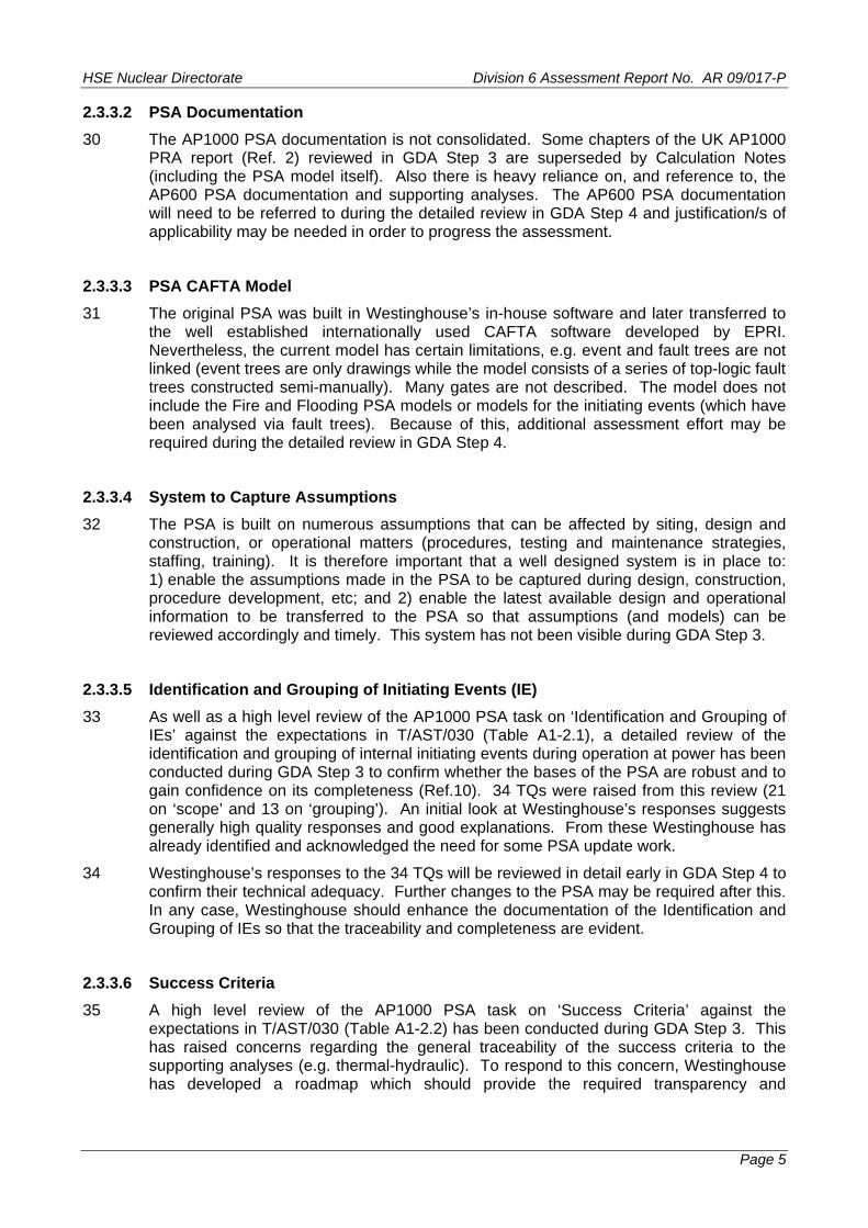
2.3.3.2 PSA Documentation
The AP1000 PSA documentation is not consolidated. Some chapters of the UK AP1000 PRA report (Ref. 2) reviewed in GDA Step 3 are superseded by Calculation Notes (including the PSA model itself). Also there is heavy reliance on, and reference to, the AP600 PSA documentation and supporting analyses. The AP600 PSA documentation will need to be referred t
30
o during the detailed review in GDA Step 4 and justification/s of applicability may be needed in order to progress the assessment.
31
s of top-logic fault trees constructed semi-manually). Many gates are not described. The model does not
ire and Flooding PSA models or models for the initiating events (which have d via fault trees). Because of this, additional assessment effort may be
2.3.3.4
32 d
esigned system is in place to: n,
l
2.3.3.5
33 a detailed review of the
ence on its completeness (Ref.10). 34 TQs were raised from this review (21 look at Westinghouse’s responses suggests
s
34 his.
2.3.3.6
35
e required transparency and
2.3.3.3 PSA CAFTA Model
The original PSA was built in Westinghouse’s in-house software and later transferred to the well established internationally used CAFTA software developed by EPRI. Nevertheless, the current model has certain limitations, e.g. event and fault trees are not linked (event trees are only drawings while the model consists of a serie
include the Fbeen analyserequired during the detailed review in GDA Step 4.
System to Capture Assumptions
The PSA is built on numerous assumptions that can be affected by siting, design anconstruction, or operational matters (procedures, testing and maintenance strategies, staffing, training). It is therefore important that a well d1) enable the assumptions made in the PSA to be captured during design, constructioprocedure development, etc; and 2) enable the latest available design and operationainformation to be transferred to the PSA so that assumptions (and models) can bereviewed accordingly and timely. This system has not been visible during GDA Step 3.
Identification and Grouping of Initiating Events (IE)
As well as a high level review of the AP1000 PSA task on ‘Identification and Grouping of IEs’ against the expectations in T/AST/030 (Table A1-2.1), identification and grouping of internal initiating events during operation at power has been conducted during GDA Step 3 to confirm whether the bases of the PSA are robust and to gain confidon ‘scope’ and 13 on ‘grouping’). An initial generally high quality responses and good explanations. From these Westinghouse haalready identified and acknowledged the need for some PSA update work.
Westinghouse’s responses to the 34 TQs will be reviewed in detail early in GDA Step 4 toconfirm their technical adequacy. Further changes to the PSA may be required after tIn any case, Westinghouse should enhance the documentation of the Identification and Grouping of IEs so that the traceability and completeness are evident.
Success Criteria
A high level review of the AP1000 PSA task on ‘Success Criteria’ against the expectations in T/AST/030 (Table A1-2.2) has been conducted during GDA Step 3. Thishas raised concerns regarding the general traceability of the success criteria to the supporting analyses (e.g. thermal-hydraulic). To respond to this concern, Westinghouse has developed a roadmap which should provide th

HSE Nuclear Directorate Division 6 Assessment Report No. AR 09/017-P
Page 6
traceability. This roadmap will be tested early in Step 4 by assessing in detail the
36
.3.3.7 Accident Sequence Analysis (Event Trees)
of the AP1000 PSA task on ‘Accident Sequence Analysis (Event
38
39 e to software failures.
0 Most event trees contain a header CHR (Containment Heat Removal) following success is is because (in the longer term) containment heat the residual heat from the reactor. However,
2.3.3.8
1 A high level review of the AP1000 PSA task on ‘Systems Analysis’ against the ducted during GDA Step 3.
Fault Tree
se Failures (CCF) have been included in the fault trees. Also, the modelling of instrumentation failures that contribute to the human errors (e.g. failure of the alarms or indications) is very simplistic
e actual instrumentation available. All these simplifications defeat the
43
diagrams are not included. Also, the PSA report does not include information on the
success criteria for two initially selected accident sequences.
Westinghouse has used conservative analyses to define the success criteria in some areas of the PSA. This could in principle distort the results of the PSA and limit its usability. Therefore, Westinghouse needs to provide details of the extent of conservatisms in the success criteria and their impact, and justify the approach adopted.
2
37 A high level review Trees)’ against the expectations in T/AST/030 (Table A1-2.3) has been conducted during GDA Step 3. Key findings are summarised below.
It is important that Westinghouse establishes the link between the accident sequences delineated in the PSA and the procedures used by the operators during the course of an accident. This link is currently missing.
Westinghouse needs to explain if and how they have evaluated potential dependencies between initiating events and mitigating systems du
4of the reactor cooling systems. Thremoval is necessary to evacuatesequences with failure of CHR are not added to the CDF or carried over to the Level 2 PSA. Westinghouse needs to demonstrate a safe stable state of the plant at the end of the (selected) PSA mission time in sequences where success of reactor cooling systems is claimed. Further development in the event trees may be needed.
Systems Analysis (Fault Trees)
4expectations in T/AST/030 (Table A1-2.4) has been con
42 A number of concerns raised during this review have been compiled in an RO that mainly addresses incompleteness of the system fault tree models and concerns on how the models have been built. For example, the models do not include pre-accident Human Failure Events (HFE) (e.g. mis-alignments and mis-calibrations) and the criteria for their exclusion are not considered adequate; the criteria for excluding structural failures and passive component failures may be optimistic for a design that bases its safety on the availability of ‘passive’ systems; the modelling of unavailabilities due to Testing and Maintenance (T&M) is asymmetric, some T&M events are embedded inside modules, and, overall this part of the models is not easily traceable; the AP1000Guidelines promote simplification of the model structure. This has been achieved by, for example, modelling basic events out of step to the logical sequence described by the gate descriptions, or by using modular events throughout without proper documentation. The simplified approach also affects the way in which Common Cau
and unrelated to thtransparency of the model and bring questions regarding whether all dependencies have been properly captured.
Other findings in the systems analysis have been brought to Westinghouse’s attention via TQs. In particular, the approach adopted for the definition of system boundaries in the AP1000 PSA is not explicit in the documentation provided. Adequate simplified system
HSE Nuclear Directorate Division 6 Assessment Report No. AR 09/017-P
Page 7
boundaries adopted for all component types modelled. In addition, the matrices that show the dependencies between components and their support systems do not explicitly
systems analysis documentation (including the fault tree guidelines) requires
A Step 4.
2.3.3.9
tep 3. So far,
ions (recoveries by other members of the operating team) seems optimistic.
r Rate Prediction (THERP) data requires substantiation
46 yet to
2.3.3.10
47
48
49 es) defined and their characteristics and identification of the
indicate which specific component in the support system delineates the interface between both systems. Because of all of this, it is felt that the current system fault tree models are prone to having gaps or overlaps. This also brings questions on whether the data and the models are consistent. Although the correctness and completeness of the system models needs to be reviewed in more detail during GDA Step 4, it is already clear that the
enhancements.
44 One of the issues encountered during GDA Step 3 is that it is not clear what the current status of development of each system design, testing and maintenance schedules and strategies is and what exactly the PSA models. Clarity on this is particularly urgent for the systems that will be reviewed in detail during GD
Human Reliability Analysis (HRA)
45 A review of the AP1000 PSA task on ‘Human Reliability Analysis’ against the expectations in T/AST/030 (Table A1-2.5) has commenced during GDA Sthis review has raised initial concerns in the following areas:
Lack of modelling / consideration of pre-initiator HFEs (discussed above in the systems assessment).
Assessment of time windows for operator actuation appears optimistic.
Consideration of post-fault diagnosis appears unrealistic.
Recovery model used in the Human Error Probability (HEP) calculat
The Technique for Human Errofor AP1000 digital interfaces and facilities.
Westinghouse has been briefed about the above but has not had the opportunity see and comment on the review report. Therefore, formal TQs / ROs have not been raised yet. This review work will continue in GDA Step 4 and will be done in coordination with the Human Factors assessment team.
Data Analysis
A high level review of the AP1000 PSA task on ‘Data Analysis’ against the expectations in T/AST/030 (Table A1-2.6) has been conducted during GDA Step 3.
For the evaluation of some initiating event frequencies (e.g. transients) Westinghouse has used operational experience data from Westinghouse reactors. However, this data is old and limited to a 5 year period, which brings a concern on its adequacy. Figures used for the frequencies of Steam Generator Tube Rupture (SGTR) and Loss of Coolant Accident (LOCA) need justification. In all cases the criteria for selection of data sources and the order of precedence of data sources used in the evaluation of initiating event frequencies is not explicit in the PSA documentation.
Data used for component reliability is old and requires updating. Details of the component types (familicomponents grouped within each type / family needs to be explicit, but it is not. Also, ND expects to receive information (description and definition) on boundaries for each component population and evidence that the component boundaries in the generic
HSE Nuclear Directorate Division 6 Assessment Report No. AR 09/017-P
Page 8
sources of data used are consistent with the boundaries used in the PSA Systems Analysis. Concerns with some component mission times have also been raised.
Data used for the CCF parameters is also old and requires updating.
It is understood that Westinghouse has programmed work to update the PSA database. ND wishes to see and discuss with Westinghouse, during GDA Step 4, the programme to do this work and the methods and data sources selected to gain confidence that the next version of the PSA database is likely to meet ND’s expectations. It is however not clear whether this effort
50
51
will also address CCF data but this data should also be updated.
2.3.3.11
52 of Hazards’ against the expectations in T/AST/030 (Table A1-2.7) has been conducted during GDA Step 3.
00 PSA does not start with a complete list of internal internal flood no analysis or screening of additional
54 000 PSA does not start with xternal
d nearby facility accidents have been screened out based on ugh follow-up a used was
s CDF is 2.41 x 10⁻⁷ /yr and g )
55
6 Westinghouse has used the method FIVE with some enhancements to conduct the A. Since FIVE is a focused screening tool with inherent conservatisms
and has now been superseded by NUREG/CR-6850, the adequacy of the
impact on circuits,
57
cant update to incorporate design
58
Step 4. Our expectation is that the review and update of the AP1000 Fire PSA should
Analysis of Hazards
A high level review of the AP1000 PSA task on ‘Analysis
53 The analysis of hazards for the AP10hazards. Apart from internal fire andpotential internal hazards (e.g. turbine missile, dropped loads) has been documented in Ref. 2. Westinghouse has been requested to provide justification for this.
In the same way, the analysis of external hazards for the AP1a complete list. From the set of hazards listed up front, high winds, tornadoes, efloods and transportation an
-6a frequency <1.0 x 10 /yr (according to the PSA documentation, althodiscussions with Westinghouse suggest that the screening criteri<1.0 x 10⁻⁷ /yr). Considering that the AP1000 internal event
-8the LRF is 1.95 x 10 /yr, there is a question on the adequacy of (either) screenincriteria. Finally, the seismic hazard is addressed via a Seismic Margins Analysis (SMAbut it is not included in the PSA.
2.3.3.11.1 Fire PSA
Currently the estimated CDF from internal fires amounts to approximately 25% of the CDF from internal initiating events, and, therefore, the relative risk significance of internal fires is non negligible.
5AP1000 Fire PSand optimisms, approach needs to be justified. In particular, concerns have been raised in the following areas of the analysis: fire frequencies, selection of cables and fire spurious actuations, fire induced explosions and missiles impacting outside the compartment boundary, multi-compartment fires and human reliability analysis for fire scenarios.
During the ND / Westinghouse ‘AP1000 PSA Step 3 Assessment Wrap-up Meeting’ (Ref. 12), it became apparent that although Westinghouse may be able to provide answers to some of the questions raised, the current Fire PSA is not a good representation of the AP1000 risk due to internal fires since it needs significhanges.
In order to compile all the concerns around the AP1000 Fire PSA an RO has been raised. In response to this Westinghouse is planning to establish and provide, within GDA timeframes, a detailed programme to update the Fire PSA, however the work will not be completed until later. ND will assess Westinghouse’s Fire PSA programme in GDA
HSE Nuclear Directorate Division 6 Assessment Report No. AR 09/017-P
Page 9
align it with up-to-date information and modern standards and, therefore, the Fire PSA programme should be accompanied by enough information on standards, approaches
ent on whether the
2
59 ternal
floods is small. However, from the review conducted so far, it appears that some aspects may be optimistic. For example, old data has been used for flood
e modern data reflects more accurately the frequency of spraying
clear
r the potential
2
60
the seismic hazard analysis for one of the NPP sites in the UK, ND’s assessment team has estimated that the mean LRF for the seismic event
ame order as the currently calculated LRF from internal events erefore, more analysis will be required to determine the seismic
61
mentation of the AP600 PSA, but the applicability of AP600 information is not
2.3.3.13 Analyses, Quantification, and Interpretation of Level 1 PSA Results
and data sources to be used to allow us to establish an initial judgemfinal Fire PSA for the AP1000 will be acceptable to ND.
.3.3.11.2 Flooding PSA
Currently the estimated CDF from internal flooding events is much smaller than the CDF from internal initiating events, and, therefore, the relative risk significance of in
of the flooding analysisfrequencies while morevents. Maintenance induced floods have not been considered. The PSA assumes that doors will remain intact and in their normal position in all flooding scenarios. It is notif / how structural failures due to the flood load, or compartment pressurisation, have been considered. ‘Immersion’ and ‘spray hazards’ are the only failure mechanisms addressed; ‘jet impingement’ and ‘high temperature and / or humidity effects’ or ‘over pressurisation’ due to high energy line breaks are not discussed. No discussion is included of the post flood human reliability analysis so it is not clear whethedegradation of human reliability in some flood scenarios has been addressed. Therefore, additional information, relevant justification or extension of the analysis will be required to address all these points.
.3.3.11.3 Seismic Hazard
Westinghouse has submitted an SMA to address seismic risk. This is not a Seismic PSA and cannot be integrated with the rest of the PSA for overall evaluation of the risk. Using the information in the SMA and
would be of the s(1.95 x 10⁻⁸ /yr). Thcontribution to the risk when site-specific information is available.
2.3.3.12 Low Power and Shutdown PSA
A review of the AP1000 PSA task on ‘Low Power and Shutdown’ against the expectations in T/AST/030 (Table A1-2.8) has started during GDA Step 3 however the review team quickly encountered problems in this particular area due to the scattered nature of the documentation of the AP1000 Shutdown PSA. For example, the UK AP1000 PRA does not present the Plant Operational States (POS) during low power and shutdown or the derivation of the IEs during low power and shutdown POSs. This appears to be included in the docuclear. In order to undertake a detailed assessment during GDA Step 4 Westinghouse has been requested to provide a reconstruction of the study from the various sources of information.
Uncertainty
62 A systematic description of all sources of uncertainty is currently missing from the AP1000 PSA report. This is necessary to confirm whether the sensitivity and uncertainty analyses are sufficient to address important uncertainties. In addition Westinghouse needs to explain what actions are being taken to reduce uncertainties that have a significant (relative) impact on the overall risk. ND requires this to gain confidence that

HSE Nuclear Directorate Division 6 Assessment Report No. AR 09/017-P
Page 10
the results of the PSA are robust and the PSA can be used in future applications to support decision making.
Regarding the parametric uncertainties Westinghouse needs to provide adequate justification of the error factors assigned and they also
63 need to explain how parametric
uncertainties of components using the same parameter (e.g. components of the same are combined in the same cutsets) have been propagated in the
65
2.3.3.14
66
67
ttributes had been followed and no step-by-step explanation of the criteria used to determine each grouping attribute based on the status of the Level 1 sequences is included.
S is calculated by adding the frequencies of all the Level 1
2.3.3.15
9 A high level review of the ‘AP1000 Deterministic Accident Progression Analysis’ that the expectations in T/AST/030 (Table A1-3.2) has been
71
tion (IVR) and hydrogen combustion. However, it was felt that the effects of alternate credible assumptions had not always been thoroughly demonstrated to be negligible.
72
type the failures of which quantification.
64 The truncation limits used in PSA quantification need to be identified and justified.
Finally, Westinghouse needs to revise the PSA documentation to reflect the quantification of the CAFTA model and its results.
Interface between Level 1 and Level 2 PSA
The review of the AP1000 Level 2 PSA started by conducting a high level review of the ‘Interface between the Level 1 and the Level 2 PSA’ against the expectations in T/AST/030 (Table A1-3.1).
The AP1000 Plant Damage States (PDS) are identified using a 2 / 3 letter code. Each Level 1 sequence is mapped to the relevant PDS by using a set of attributes. However, no evidence is provided in the reviewed documentation that a systematic process to identify and select PDS a
68 The frequency of each PDsequences. Each PDS is connected to a Containment Event Tree (CET). Careful application of Westinghouse’s methodology to address the interface between the Level 1 and Level 2 PSA should be capable of correctly transferring information from the Level 1 sequences to the Level 2 CETs, but lack of transparency in the process was noted.
Deterministic (Severe) Accident Progression Analysis
6supports the Level 2 PSA against conducted during GDA Step 3.
70 The deterministic accident progression analyses for the AP1000 have been done using the MAAP4 code. A summary of these analyses is presented in the PSA documentation. Detailed documentation (and input decks) of individual MAAP4 calculations need to be provided by Westinghouse so that they can be assessed during GDA Step 4.
The accident progression analyses are usually specific to the AP1000, although a considerable amount of information is drawn from earlier analysis for the AP600, with scaling arguments and adjustments. The parametric sensitivity to selected assumptions is examined in areas such as depressurisation of the Reactor Pressure Vessel (RPV), In-Vessel Reten
2.3.3.16 Containment Performance Analysis
A high level review of the ‘AP1000 Containment Performance Analysis’ against the expectations in T/AST/030 (Table A1-3.3) has been conducted during GDA Step 3.

HSE Nuclear Directorate Division 6 Assessment Report No. AR 09/017-P
Page 11
73 ations and no evidence was found of a systematic search for,
e been ess of
75 ent AP1000 LRF is not very sensitive to the ultimate capacity of the containment – this is probably due to the fact that the currently estimated
e conservative assumptions regarding while still presenting a LRF that is small.
pite its currently perceived low importance from the risk point
2.3.3.17
76 4) has been conducted during GDA Step 3.
the correspondence between the documentation and the model to be reviewed.
e selection of phenomena h ome events have been
cies for events in the CET may have been ignored when
2.3.3.18
80
ypassed. A common Source Term is then developed for each RC based solely on the mode (time) of containment failure without further discrimination of accident sequence characteristics or severe accident phenomena. As a result, there is a wide
s enveloped within each RC. This lack of detail
The analysis of the AP1000 containment performance is based on typical containment failure mechanisms and locand evaluation of, all plausible mechanisms and locations of containment failure. Qualitative arguments are used to dismiss the contributions of smaller mechanical and electrical penetrations; these are not considered sufficient. Furthermore, it is not clear from the documentation provided to what extent stress concentration around small penetrations is addressed in the structural response calculations.
74 The contributors to the uncertainty in the ultimate capacity of the containment havquantified by expert judgment, but no evidence was found of a systematic proceliciting expert judgment for this purpose.
According to Westinghouse, the curr
low CDF allowed Westinghouse to makcontainment performance in the Level 2 PSA This approach may be no longer adequate if future revisions of the PSA show a higher CDF. This is the reason why assessment of this aspect of the Level 2 PSA will be pursued in GDA Step 4 desof view.
Level 2 PSA Probabilistic Modelling Framework: Containment Event Trees (CET)
A high level review of the AP1000 Level 2 PSA CETs against the expectations in T/AST/030 (Table A1-3.
77 The Level 2 PSA documented in Ref. 2 indicates that CETs are not linked fault tree type. This is different to the CAFTA model which appears to present a fully linked fault tree Level 2 model, which however is not documented in detail in any of the references seen during GDA Step 3. So, in order to continue with the detailed assessment of the Level 2 PSA during GDA Step 4, clarification is being sought from Westinghouse on
78 Not sufficient evidence was found of a systematic process for th included in the CET and therefore, it is not clear up front w y sincluded or excluded from the CET. Questions have also been raised on some details of the approach used to evaluate the CET nodal probabilities. An initial review of the CETs suggests that human dependengenerating probabilities for the CET nodes. This could be important and needs to be explored in further detail during GDA Step 4.
Source Term Analysis
79 A high level review of the AP1000 Level 2 PSA ‘Source Term Analysis’ against the expectations in T/AST/030 (Table A1-3.4) has been conducted during GDA Step 3.
Each CET sequence is mapped to a Release Category (RC). RCs are defined in terms of containment failure at different nodes in the CET. RCs are classified as ‘large release’ (and their frequency added to the LRF) for any CET sequence in which the containment fails or is b
range of radiological release scenariomay distort any evaluation or understanding of the relative contribution of systems, sequences or phenomenological issues to overall (risk and release frequency) results and may hinder a meaningful comparison against the Numerical Targets of the SAPs.

HSE Nuclear Directorate Division 6 Assessment Report No. AR 09/017-P
Page 12
81 The Source Term for each RC is evaluated by selecting a single representative sequence. A justification of how the sequence is selected or of the adequacy of this simplified approach is not included in Ref. 2. No information has been found to identify and characterise the efficiency of important retention mechanisms, locations of deposited material, of the dominant factors contributing to differences in the releases among the RCs. Also, for the Source Term characterisation some assumptions have been made (e.g. releases are assumed to be continuous, have a constant release rate, are from the
the fractional releases to offsite dose is not
2.3.3.19
82
ment.
Containment Effectiveness (Ceff): ratio of intact containment frequency to core
85 rm for each
86
dditional analysis. It was noted that the success sequences of the Level 1 PSA do not appear to have been considered for their potential low dose band contribution. Furthermore, it is not clear at this stage that the
performed in a way that facilitates easy comparison with the
2.3.4
88
ground level and have no internal energy) for which the technical basis are not clear. Each Source Term is then presented in terms of cumulative and time-dependent release fractions of radionuclide groups to the environment however the assumed isotopic inventory of radionuclides used to translatedescribed.
Presentation and Interpretation of the Level 2 PSA Results
The numerical results of the Level 2 PSA are presented in terms of:
Large Release Frequency (LRF): frequency of all Release Categories except intact contain
damage frequency.
83 The documentation presented by Westinghouse for Step 3 compares the above results with targets derived from the United States Nuclear Regulatory Commission (US NRC) Safety Goals, rather than UK targets.
84 Sensitivity analyses have been performed but propagation of uncertainties (Level 1 parametric uncertainties, Level 2 uncertainties or combination of these) to the LRF has not been performed.
A limited scope Level 3 PSA analysis has been presented in Chapter 49 of Ref. 2 which uses as input the Level 2 PSA results in terms of frequency and Source TeRC and certain assumptions on demography and weather. The estimated site boundary whole-body dose and the acute red bone marrow dose are compared to the Westinghouse goal of <25 rems (0.25 sieverts), at a frequency not to exceed 1 x 10⁻⁶ /yr.
Some consideration of UK targets is provided in the ‘Safety Assessment Principles Roadmap for AP1000 Design’ (Ref. 13). In this document, Numerical Targets 5 to 9 of the SAPs are addressed based on the PSA presented in Chapter 19 of Ref. 3. Compliance is claimed on this basis without a
Level 2 PSA has been Numerical Targets in the SAPs related to offsite consequences, i.e. it is not clear that a mapping of RCs to Dose Bands (HSE Target 8) and a mapping of RCs corresponding to a ‘large accident’ (societal risk in HSE Target 9) can be established.
87 A Severe Accident Management Design Alternatives (SAMDA) analysis is presented which is intended to support the ALARP demonstration. Potential modifications (design alternative) have been assessed in this analysis.
Requirements of GDA Guidance
The guidance to RPs on GDA required them, at Step 3, to include a PSA. Ref. 2 and supporting documentation fulfil that requirement.
HSE Nuclear Directorate Division 6 Assessment Report No. AR 09/017-P
Page 13
89 HSE undertakings for Step 3 for PSA items 3.15, 3.22, and 3.23 of the GDA guidance (Ref. 16) are the main points to consider:
3.15 is addressed by this report.
3.22 is addressed by TQs and ROs raised to date.
3.23 is addressed by comparison with numerical targets (note these may change as a result of ongoing design and assessment).
In relation to 3.26, PSA is not a major overlap for the Environment Agency.
Use of Oth
90
2.3.5 er Regulators Information
1 Westinghouse has provided a list of questions raised by US NRC during its assessment All of this will be reviewed ress and findings of the
ther members of the
2.3.6
92 ep 4 assessment will look in detail at all the areas reviewed at a
ing the structure established in Appendix 1 of ND’s
hniques used is adequate. In addition to this, specific items
2.3.7
2.3.8
94 A (Ref. 14). All TQs
reclude further TQs for greater detail, should they be needed or indeed issue of ROs or RIs).
9of the AP1000 PSA and the responses sent by Westinghouse. and where relevant included in ND’s assessment. The progassessment of the AP1000 PSA will be also discussed with the oAP1000 Multi-national Design Evaluation Programme (MDEP) as / if required.
Plans for GDA Step 4 Assessment
It is intended that the Sthigh level in Step 3, using, as the basis, the original PSA documentation and all the additional information received in response to the TQs and ROs raised. All the technical areas of PSA will be addressed followPSA guide (Ref. 8). However, not each and every fault tree, event tree, supporting analysis or item of reliability data, will be examined in detail. Rather, the aim is to establish, by reviewing in detail a representative sample, whether the implementation of the methods and tecidentified in Step 3 that require follow-up during the Step 4 assessment will be listed in the GDA Step 4 Project Plan for the AP1000 PSA.
Related Research
93 We have identified a potential need to research in the area of Human Reliability Analysis (HRA). The AP1000 HRA uses the well known THERP (NUREG/CR-1278, 1983) data but the AP1000 design, particularly for all control room post-fault actions uses interfaces that are very different to those assumed in the THERP data sets. ND needs to form a view on the work that would be necessary to evaluate THERP data against digital interfaces and whether some research work needs to be commissioned.
Technical Queries (TQ)
During Step 3 we have issued 85 TQs covering all aspects of the PShave been acknowledged by Westinghouse and full or partial responses have already been provided for many of them. The responses to the TQs will form the basis for ongoing assessment (this of course does not p
HSE Nuclear Directorate Division 6 Assessment Report No. AR 09/017-P
Page 14
2.3.9 Regulatory Observations (RO)
In two areas it has been clear that there are95 shortfalls that cannot be clarified via TQs. To e been issued (Ref. 15):
dels’. This RO addresses the
the AP1000 Fire PSA, both approach and
2.3.11
7 No firm exclusions have been identified during the assessment in GDA Step 3. However, the potential for exclusions or conditions related to PSA is discussed in Section 2.3.1
address these the following ROs hav
‘PSA Systems Analysis Guidelines and Systems Moobserved incompleteness in the AP1000 systems fault tree models.
‘Fire PSA’. This RO addresses the fact thatdata used, are out of date.
2.3.10 Regulatory Issues (RI)
96 In the PSA area we have not identified any failings or shortfalls of sufficient magnitude to warrant the issue of an RI for the PSA itself.
Potential Exclusions
9
above.

HSE Nuclear Directorate Division 6 Assessment Report No. AR 09/017-P
Page 15
3 CONCLUSIONS AND RECOMMENDATIONS
cal areas against the tables SA er’
r I conclude the
99 of the basis to interpret the risk associated with this reactor and where the main design strengths and relative
wever, shortcomings in scope, methods and data identified work will be required to complete and modernise the PSA so
0 In addition, I believe that further development will be required in the future to provide the ail which can support modern decision making tools such as a
(as represented by Target 9 of the SAPs) lies below the Basic Safety Level (BSL). At the moment, I do not have any reason to believe that this position will change dramatically once the PSA has been completed and updated.
102 Finally, I believe that Westinghouse’s PSA team are making a significant effort to establish a programme of work to update the AP1000 PSA and bring it to modern standards. They appear to be listening and taking on board feedback given by the ND team and they seek and value the opinion of other peers in the US. Discussions between ND and Westinghouse’s PSA team during GDA Step 3 have continually been open and positive.
103 Overall, I see no reason, on PSA grounds, why the AP1000 should not proceed to Step 4 of the GDA process.
104 From the AP1000 PSA assessment work done so far I recommend the following:
Recommendation 1: All the items identified in Step 3 as important to be followed up should be included in ND’s GDA Step 4 Project Plan for the AP1000 PSA.
Recommendation 2: Considering the (extensive) current, planned and expected developments of the AP1000 PSA, two technical exchange workshops should be scheduled during GDA Step 4 to discuss in depth the PSA work being done by Westinghouse in the different areas including methods, sources of data and progress. The information compiled from, and outcome of, these workshops should be used to inform ND’s Step 4 assessment and its final (GDA Phase 1) position regarding the AP1000 PSA.
98 Westinghouse has provided a PSA as part of the AP1000 submission to HSE-ND for GDA. During Step 3 a high level review of all the PSA technicontained in Appendix 1 of ND’s PSA guide (Ref. 8) and a detailed review of the PTask on ‘identification and grouping of internal initiating events during operation at powhave been conducted. From the AP1000 assessment work done so fafollowing:
The current PSA with its current scope provides part
vulnerabilities may lie. Hoduring Step 3 indicate that that it can provide a more adequate input into the demonstration that the risk associated with the AP1000 is ALARP.
10PSA with the level of detRisk Monitor
101 Having said that, the current Core Damage and Large Release Frequencies presented by Westinghouse provide a degree of confidence that the Societal Risk associated with the AP1000

HSE Nuclear Directorate Division 6 Assessment Report No. AR 09/017-P
Page 16
4 REFERENCES
1 New Reactor Build – Westinghouse AP1000 Step 2 PSA Assessment. ND Division 6 Assessment Report No. AR08/009, HSE, March 2008. TRIM Ref. 2008/86523.
UK AP1000 Probabilistic Risk Assessment. UKP-GW-GL-022, Revision 0, Westinghouse Electric Company LLC, May 2007.
AP1000 Eu
2
3 ropean Design Control Document. EPS-GW-GL-700, Revision 0,
4
5
8
9 , Rev 0, Jacobsen
10
11 esign Assessment Step 3 – Review of Human Reliability Assessment for the
. 9.
13 Safety Asses 1, Rev 0,
14 WestinghousNovember 2
15 WestinghousHSE-ND, No
16 Nuclear pow uidance to requesting parties. (Version 3) HSE, August 2008.
Westinghouse Electric Company LLC, February 2009.
Safety assessment principles for nuclear facilities. 2006 Edition, Version 1, HSE, December 2006.
New Reactor Build Step 3 PSA Strategy. ND Division 6 Assessment Report No. AR08/029, HSE, March 2008. TRIM Ref. 2008/317683.
6 Safety Assessment and Verification for Nuclear Power Plants. IAEA Safety Standards Series, Safety Guide NS-G-1.2, International Atomic Energy Agency (IAEA), Vienna, 2001.
7 Reactor Safety Reference Levels. Issue O, Western European Nuclear Regulators Association (WENRA), January 2008.
Probabilistic Safety Analysis, Technical Assessment Guide. T/AST/030, Issue 3, Health and HSE Nuclear Directorate, February 2009.
Review of the AP1000 PSA for Step 3 of GDA. JEL1-HSE-0803Engineering Ltd, October 2009. TRIM Ref. 2009/434983.
Review of the UK AP1000 PRA – Internal Initiating Events during Full Power Operation. JEL2-HSE-0309, Rev 1, Jacobsen Engineering Ltd, Stetkar J, July 2009. TRIM Ref. 2009/434989.
Generic DAP1000 PSA. PR-2152-1, Greenstreet Berman / Synergy (Consortium), August 2009. TRIM Ref. 2009/415396.
12 AP1000 Probabilistic Safety Analysis - GDA Step 3 Assessment Wrap-up MeetingNuclear Directorate Division 6 Contact Report No CR09148, HSE-ND, August 200TRIM Ref. 2009/347567.
sment Principles Roadmap for AP1000 Design. UKP-GW-GL-74Westinghouse Electric Company LLC, November 2008.
e AP1000 - Schedule of Technical Queries Raised during Step 3. HSE-ND, 009. TRIM Ref. 2009/358248.
e AP1000 - Schedule of Regulatory Observations Raised during Step 3. vember 2009. TRIM Ref. 2009/358257.
er station generic design assessment – g

HSE Nuclear Directorate Division 6 Assessment Report No. AR 09/017-P
Page 17
Table 2
H
SE – ND Safety Assessment Principle Compliance – Probabilistic Safety Analysis
SAP Interpretation Comment
Fault analysis: PSA – Need for A.10
This principle sets the framework and requirements for a PSA
Addressed in paras 5 ta PSA – F
should be f
velopm
judgements on the safety of the
o 10, 22 to 25 and 99 of this report.
“Suitable and sufficient PSA
performed as part o
study. The overriding aim of the PSA assessment is to assist ND
the fault analysis and design de ent and analysis”
facility and whether the risks of its operation are being made as low as reasonably practicable.
Fault analysis: PSA – Validity – This principle establishes the need for each aspect of the PSA
Addressed throughout this report but in particular in paras 30, 32 FA.11
sign anfacility or
to be directly related to existing
e absence of
su a
and 61.
“PSA should reflect the current de d operation of the
site”
facility information, facility documentation or the analysts’ assumptions in th
such information. The PSA should be documented in chway as to allow this principle to be met.
Fault analy exten
“PSA sho
rces of ras of in
at the fac
ility (e.g. fuel ponds, fuel
tiating faults (e.g. internal
power, shutdown, start-up,
ssed in paras 7, 22, 27, 33, sis: PSA – Scope In order to meet this principle the Addreand t – FA.12
uld cover all significant
scope of the PSA should cover all sources of radioactivity at the fac
34, 53, 54 and 61 of this report.
sou dioactivity and all type itiating faults identified
ility or site”
handling facilities, waste storage tanks, radioactive sources, reactor core, etc), all types of inifaults, internal hazards, external hazards) and all operational modes (e.g. nominal full power, lowrefuelling, maintenance outages).
Fault anaesen
“The PSAdequ
ata and
the facility.
ssed in paras 35 to 81 of this lysis: PSA – Adequate The aim of this principle is to Addrerepr tation – FA.13
model should provide
ensure the technical adequacy of the PSA. Inspectors should review PSA models, d
report.
an a ate representation of the site and its facilities”
results to be satisfied that the PSA has a robust technical basis and thus provides a credible picture of the contributors to the risk from
FPSA – FA.14
ault analysis: PSA – Use of
SA should be used to inform e design process and help
nsure the safe operation of the cilities”
The aim of this principle is to establish the expectations on what uses the duty-holders should make of the PSA to support decision-making and on how the supporting analyses should be undertaken.
Addressed in paras 5, 32, 87, 99 and 100 of this report.
“Pthesite and its fa

HSE Nuclear Directorate Division 6 Assessment Report No. AR 09/017-P
Page 18
SAP Interpretation Comment
N
umerical Targets
Target 7: Indipeople off the site from accidents
nts on an off
Addressed in paras 83 to 86 of this report.
vidual risk to
Target 8: Frequency dose argets for accidet
individual facility – any personthe site Target 9: Total risk of 100 or more fatalities
NT.2 Not addressed in GDA Step 3.
HSE Nuclear Directorate Division 6 Assessment Report No. AR 09/017-P
Annex 1 - Page 1
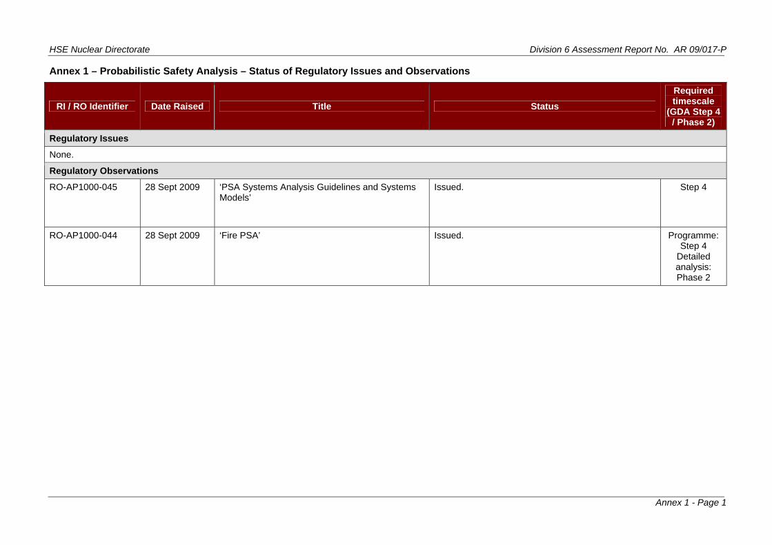
Annex 1 – Probabilistic Safety Analysis – Status of Regulatory Issues and Observations
RI / RO Identifier Date Raised Title Status
Required timescale
(GDA Step 4 / Phase 2)
Regulatory Issues
None.
Regulatory Observations
RO-AP1000-045 28 Sept 2009 ‘PSA Systems Analysis Guidelines and Systems Models’
Issued. Step 4
RO-AP1000-044 28 Sept 2009 ‘Fire PSA’ Issued. Programme:
s:
Step 4 Detailed analysiPhase 2

HSE Nuclear Directorate Division 6 Assessment Report No. AR 09/017-P
Annex 2 - Page 1
Annex 2
Detailed assessment against T/AST/030 expectations
Additional information on the assessment of the AP1000 PSA conducted during Step 3 of the Generic Design Assessment (GDA) is presented below under the headings of the ‘Table of Assessment Expectations’ in Appendix 1 of the HSE Nuclear Directorate’s (ND) Probabilistic Safety Analysis (PSA) Technical Assessment Guide (TAG) (Ref. 8). Points arising from this step of the assessment where clarification or additional information have been sought have been the subject of Technical Queries (TQ) or Regulatory Observations (RO) and will be tracked to completion through a purpose designed GDA administrative system.
Unless otherwise stated references to section or chapter numbers relate to the AP1000 PSA report (Ref. 2) supporting the AP1000 GDA submission (Ref. 3).
Further details of the review work done can be found in Refs 9 to 11.
It should be noted that for most of the assessment expectations in ND’s PSA guide (Ref.8) a detailed review (of a representative set of examples) still needs to be performed in Step 4 of the GDA, to verify that the stated intent / methods that the PSA has employed (as reviewed in Step 3 of the GDA) have been implemented as correctly, consistently and completely as possible.
Re Table A1-1 General E ctationf. 8, xpe s
1 Two points are worth highlighting up front. These are related to the PSA documentation and to the system to capture PSA assumptions.
2 The AP1000 PSA documentation is not consolidated. Some chapters of Ref. 2 have been superseded by Calculation Notes (including the PSA model itself). Also there is heavy reliance on, and reference to, the AP600 PSA documentation and supporting analyses. This is not a desirable position or in line with modern PSA standards. For each instance in which the AP10needed to progress the assessment during Step 4. In any case, Westinghouse should develop, as soon as possible, a self-standing and comprehensive documentation for the AP1000 PSA.
3 For all technical areas of the PSA, ND’s guide (Ref. 8) sets up an expectation that, in the absence of facility-specific information, all the assumptions made should be described and justified and a system should be in place to ensure that relevant assumptions are captured in future developments (e.g. of the design or procedures).
4 PSA assumptions could be affected by siting, design and construction, or operational matters (e.g. procedures, maintenance and testing strategies, training programmes, Main Control Room staff d or isation, etc), and, thus, they need to be reviewed when detailed information becomes available. Therefore, a system to capture assumptions should really serve two purposes: 1) enable the assumptions made in the PSA to be captured during design, construction, procedure development, etc, and 2) to enable the latest available design and operational information to be transferred to the PSA so that assumptions (and models) can be reviewed accordingly. Such a system has not been visible during GDA Step 3.
Ref. 8, Table A1-1.2 PSA Scope
00 PSA relies on the AP600 PSA, justification of applicability may be
ing an gan
5 The purpose of the PSA that has been stated in Chapter 1 of Ref. 2 is to satisfy the United States Nuclear Regulatory Commission (US NRC) regulatory requirements that a design-specific Probabilistic Risk Assessment (PRA) be conducted as part of the application for

HSE Nuclear Directorate Division 6 Assessment Report No. AR 09/017-P
Annex 2 - Page 2
design certification (10 CFR 52.47(a)(i)(v)). No mention is made of the PSA to support the application to
6 The scope of the AP1000 PSA has therefore been based on the regulatory requirements to obtain design approval for the US NRC in the mid 1990s. Thus, there are gaps
spent fuel pond. This was not reviewed during
ening out, without adequate
the UK HSE for the purposes of the GDA.
between the PSA submitted and the requirements to support a safety case submission in the UK as set out in the TAG T/AST/030 (Ref 8).
7 The scope of the PSA included in Ref. 2 considers only potential core damage scenarios. Low consequence, high frequency sequences, potential risks from fuel ponds, fuel handling facilities and waste storage facilities are not included. Report ‘AP1000 PRA Spent Fuel Pool Evaluation’ (UKP-GW-GL-743 Rev 0), submitted separately to ND, addresses the risk associated with the GDA Step 3 and, thus, it is not clear how the results of this analysis integrate with the overall PSA results.
8 The treatment of external hazards has been based on screjustification, all external hazards other than earthquakes, which have been analysed via a qualitative Seismic Margins Analysis (SMA). As the Seismic Margins Assessment is a qualitative assessment, it cannot be directly integrated into the PSA. The internal fire and flooding analyses are quantitative but are also not integrated into the overall PSA results.
Ref. 8, Table A1-1.3 Freeze Date
9 A Freeze Date or Design Freeze Reference is not clearly stated or referenced in the PSA, and there are systems that have had design changes implemented and have not been reflected in Ref. 2 (e.g. 11kV power supplies for UK design, but PSA models 6.9kV power
R
supplies).
ef. 8, Table A1-1.4 Computer Codes and Inputs
Level 1 and Level 2 PSA computer codes and inputs are not well documented in the main PSA report (Ref. 2). For example, it is not clear in this report what code was used to quantify the Level 1 PSA and the documentation does not provide the drawings for all the inputs to the m
10
odels (e.g. fault trees for the Initiating Events, Modules and Control and
CAFTA model has
11
t they will be key references to be used for the detailed assessment of the PSA during GDA Step 4 together with appropriate justification of the applicability of AP600 evaluations to the AP1000.
PSA TAG (Ref. 8) in relation to computer codes and inputs should
Instrumentation, C&I, are not provided). However, this is of little significance bearing in mind that although the original PSA was built in Westinghouse’s in-house software, it was later transferred to the well established internationally used CAFTA software developed by the Electric Power Research Institute (EPRI). Nevertheless, the certain limitations, e.g. event and fault trees are not linked (event trees are only drawings while the model consists of a series of top-logic fault trees constructed semi-manually). Many gates are not described. The model does not include the Fire and Flooding PSA models or models for the Initiating Events (IE) which have been analysed via fault trees. Because of this, additional assessment effort may be required during the detailed review in GDA Step 4.
In addition heavy reliance is made on the PSA and the supporting analyses performed for the AP600 design. The AP600 documentation and supporting analyses were not consulted during Step 3 bu
12 The expectations of the be addressed on a case by case basis during the detailed assessment of the individual technical areas, as appropriate, in GDA Step 4.

HSE Nuclear Directorate Division 6 Assessment Report No. AR 09/017-P
Annex 2 - Page 3
Ref. 8, Table A1-2 Level 1 PSA
ef. 8, Table A1-2.1 Identification and Grouping of Initiating EventR s
eness. The detailed review of the
14
s and concerns. Items that remained unresolved formed the basis
15
6 An initial look at Westinghouse’s responses suggests generally high quality responses and good explanations. From these Westinghouse has already identified and
r some PSA update work.
f Initiating Events so that the traceability and completeness are evident.
ent: Determination of Success Criteria
13 As well as a high level review of the AP1000 PSA task on ‘Identification and Grouping of Initiating Events’ against the expectations in T/AST/030 (Table A1-2.1), a detailed review has been conducted during GDA Step 3 to confirm whether the bases of the PSA are robust and to gain confidence on its complet‘Identification and Grouping of Initiating Events’ has focused exclusively on internal initiating events for the full power operating mode.
The review benefited substantially from meetings with Westinghouse’s PSA team held at the Westinghouse offices in Monroeville from 23 to 27 March 2009 during which a number of items were raised with Westinghouse’s team (PSA and engineering personnel). All these items are documented in Ref. 10. In some cases, the discussions effectively resolved the questionfor 34 TQs (21 on scope and 13 on grouping of initiating events). The background to each TQ is documented in Ref. 10.
The outcome of the review indicated that there may be a number of IEs missing from the PSA’s Fault Schedule. Also, some IEs appear to have been grouped incorrectly.
1
acknowledged the need fo
17 Westinghouse’s responses to the 34 TQs will be reviewed in detail early in GDA Step 4 to confirm their technical adequacy. Further changes to the PSA may be required after this. In any case, Westinghouse should enhance the documentation of the Identification and Grouping o
Ref. 8, Table A1-2.2 Accident Sequence Developm
19
antification of the Human Failure Events (HFE) modelled in the PSA to
20
Summary) of the PSA document (Ref. 2) however states that “It is important to note that, in general, these are not best-estimate
18 The main references for the derivation of success criteria for the AP1000 PSA were: Appendix A of the PSA report (Ref. 2), Chapter 15 of the AP1000 European Design Control Document (Ref. 3), and the AP600 PSA. It was noted that the references to Chapter 15 of the Design Control Document (DCD) in Table 6-2 of the PSA report were too vague to lead the reviewer back to specific analysis cases and that while references to Appendix A of the PSA report are more specific (the Appendix provides definitions of cases) the linkage between the defined cases and actual code runs and the configuration controls applied are not transparent. Reviewers should be able to trace backwards from a specific success criteria claim that they wish to review, through to the specific calculation which justifies the claimed success criteria. The availability of this information will be essential to undertake the detailed PSA review in GDA Step 4.
Also, the timing for operator actions should be justified by sufficient and representative thermal-hydraulic analyses, however, the traceability of the time windows used for the analysis and quspecific cases and analyses was not clear.
In response to the concerns above, Westinghouse has developed a roadmap which should provide the required transparency and traceability. This roadmap will be tested early in Step 4 by assessing in detail the success criteria for two initially selected accident sequences.
21 ND’s PSA guide (Ref. 8) requires that the thermal-hydraulic, neutronics (and any other) analyses used for derivation of success criteria should be performed on a best-estimate basis. Section 6.3.4 (Sequence Success Criteria

HSE Nuclear Directorate Division 6 Assessment Report No. AR 09/017-P
Annex 2 - Page 4
success criteria. Criteria have been selected to bound the spectra of conditions identified categories, in order to avoid
22
R
in Appendix A as being important for the various event quantifying uncertainty bounds for the success criteria”. It is therefore not clear the impact of the stated conservatisms in the success criteria on the overall PSA results.
Finally, some clarification will be required to be able to understand and trace the information contained in the tables in Chapter 6 of Ref. 2.
ef. 8, Table A1-2.3 Accident Sequence Development: Event Sequence Modeling
24 needs to be clear. In the absence of fully
it is not
he AP600 PRA. There are no new
no significant additional information is provided there). For the detailed PSA review during
OP) and se of an
25
have been searched for
initiating events and mitigating systems due
26
This is because (in the longer term) containment heat removal is necessary
23 The link between the various headings / nodes of the event trees and the relevant thermal-hydraulic analyses performed to support the event sequence modelling should be transparent. As already discussed above there is an issue with the traceability of the thermal-hydraulic analyses supporting event sequence definitions.
The link between the various headings / nodes of the event tree and the potential operational and emergency procedures developed procedures, the assumptions regarding any procedures to be developed have to be explicit and justified. Each event class section of Chapter 4 of Ref. 2 has a sub-section clearly identifying operator actions which have been credited. However,very clear what the basis for the choice of the operator actions credited is. Section 30.1 Human Reliability Analysis (HRA) of Ref. 2 states “The AP1000 human reliability analysis (HRA) is the same as was provided in Chapter 30 of toperator actions modelled in the AP1000 PRA. The operator actions, available action times and other associated assumptions made in the AP600 HRA can be applied to the AP1000”. Therefore, the AP600 study (together with the justification of its applicability to AP1000) will be a key reference to be used for the detailed assessment of the PSA during GDA Step 4 (although an initial look at Chapter 30 of the AP600 PRA suggests that
GDA Step 4 ND will also need the AP1000 Emergency Operating Procedures (Eany other relevant procedures that the operators might use during the couraccident. In any case Westinghouse should establish, as soon as possible, the link between the accident sequences delineated in the PSA and the procedures designed to be used by the operators during the course of an accident.
In principle it appears that the identification and treatment of dependencies in the AP1000 sequence analysis is reasonable. Further confirmatory review will be required during GDA Step 4. However, there is an area that has not come across in a transparent fashion; this is related to dependencies that may arise because of the specific characteristics of the design. An example is dependencies between IEs and mitigating systems due to software failures (including common cause software failures between the control system and the protection system). Whether there is evidence that this type of dependencies (called ‘subtle dependencies’ in T/AST/030) systematically by Westinghouse may be checked on a case-by-case basis during GDA Step 4. In the mean time, and in order to address some general concerns regarding the extensive use of digital systems in modern designs, Westinghouse should explain whether and how the potential dependencies betweento software failures have been evaluated and reflected, if appropriate, in the PSA.
Most event trees contain a header Containment Heat Removal (CHR) following success of the reactor cooling systems (passive reactor heat removal, RHR, normal RHR or recirculation). to evacuate the residual heat from the reactor. Sequences with failure of this final CHR header are stored under the Late Containment Failure (LCF) end state which has a frequency of 6.92 x 10⁻⁸ /yr. However, these sequences are not added to the Core Damage Frequency (CDF) or carried over to the Level 2 PSA. This appears to imply that

HSE Nuclear Directorate Division 6 Assessment Report No. AR 09/017-P
Annex 2 - Page 5
air cooling of the containment is being claimed but it is not clear whether or not this is justified by supporting transient analysis. Westinghouse needs to demonstrate a safe stable state of the plant at the end of the (selected) PSA mission time in sequences where success of reactor cooling systems is claimed. Further development in the event trees
ef. 8, Table A1-2.4 Systems Analysis
may be needed.
R
Ref. 8, Table A1-2.4.1 General Methodological Aspects
27 In PSA system analysis it is very important that the approach used for the definition of system boundaries is stated and is adequate. This is because there is a need to ensure modelling consistency among the different system analysts so that there are neither gaps, nor overlaps between the different system models. This would normally be dealt with in
28
29 AP1000 fault trees, Chapter
out pre-
the System Analysis Task Procedure. However, the AP1000 PSA Fault Tree Guidelines (Chapter 7 of Ref. 2) do not explicitly provide an approach for the identification and definition of system boundaries. This may lead to additional effort during GDA Step 4, as the review will have to be conducted using detailed system drawings in all cases (e.g. Piping and Instrumentation Diagrams, P&ID) instead of the PSA descriptions and simplified diagrams and cross-reviews between the different systems will need to be undertaken.
In PSA system analysis it is also very important that the approach used for the definition of component boundaries is stated and is adequate. Again this is because there is a need to ensure modelling consistency among the different system analysts and also with the data analysts. In Chapter 7.3.5 of Ref. 2 standardised power and control boundaries and failure modes for 4 types of components have been defined but not for all component types included in the PSA models. Component boundaries should be defined for all component types modelled so that the failure modes associated with each component type can be checked. Component boundaries in data sources can then also be checked against the boundaries of the components modelled in the PSA to confirm the applicability of the data used.
In relation to the approach used for the inclusion of pre-accident Human Failure Events (HFE) (e.g. misalignments and mis-calibrations) in the 7.3.4.1, of Ref. 2 describes the criteria for identifying this type of HFE. The review team believes however that the method for identifying these types of failures is not appropriate. First of all, the method seems to deal exclusively with mispositions of valves but does not appear to consider at all that pre-accident human errors can lead to valves, pumps, bus-bars, etc, being left de-energised (and unable to actuate on receipt of a safety signal). Equally, mis-calibrations are mentioned but not addressed in any detail. It is also believed that the criteria for screening out these types of failures are weak. For example, the screening criteria indicate that misposition of valves should only be included in the fault tree if the HFEs could seriously degrade or fail the system. This screening criterion is not adequate since the impact of a valve misalignment on the failure of the system will be different for different success criteria in different initiating events or sequences. Equally, the impact of a misalignment on the overall risk depends on each sequence and the amount of plant available to cope with the event. Also, the criteria for screening accident HFEs rely on testing intervals and strategies and alarm design and operational philosophy that have not yet been decided for the AP1000. Therefore, it is possible that the current criteria have the potential to screen out of the models latent HFEs with significant risk contributions (in particular Risk Achievement Worth). Indeed, a more detailed look at some system fault trees has identified that no pre-accident HFEs have been included in the AP1000 PSA models, thus hindering the ability of the PSA to provide support for the development of the surveillance, maintenance and testing strategies, design of the control room displays, development of procedures, etc.
HSE Nuclear Directorate Division 6 Assessment Report No. AR 09/017-P
Annex 2 - Page 6
30
e with modern PSA standards. Guidelines on what components are subject to CCF (and thus which CCF events should be explicitly modelled) or what other CCF aspects the system analyst should consider when developing the system models
ment, it is not clear that the modelling of CCF is consistent detail in GDA Step 4. CCFs could be sue has potentially high importance.
32 e (Ref. 8) expects that the approach for the inclusion of passive component
ese failures are included in Table 32-1 (Generic Data Base) of Ref. 2,
33
34
35
The AP1000 Fault Tree Guidelines (Chapter 7 of Ref. 2) require including at least one Common Cause Failure (CCF) in each system model without further guidance. More detailed CCF analysis is reported in Chapter 29 of Ref. 2. The guidance provided to the fault tree analysts is not sufficient to ensure complete and correct CCF modelling and it is not in accordanc
should be provided. At the mothroughout. This will need to be checked inimportant risk contributors and, therefore, this is
31 No discussion on the potential inclusion of structural failures could be found except for a related statement on Chapter 7.3.1.1 of Ref. 2 that indicates “Piping faults considered to be credible include: pipe plugging, orifice plugging, and plugging from chemical crystallization due to the loss of the pipe heat tracing system”. A discussion of potential structural failures and consequential structural failures (e.g. pipe whip) should be provided together with a justification of why these have not been modelled in the PSA. It should be noted that structural failure probabilities are provided in Table 32-1, Generic Data Base, of Ref. 2, thus, the concern noted here relates exclusively to the modelling of these failures in the fault trees.
ND’s PSA guidfailures into the systems should be stated and adequate. The term passive component failures refers both to the failures of passive components discussed in the previous paragraph and also to the failures of components to remain in the required position. Chapter 7.3.1.1 of Ref. 2 describes Westinghouse’s rules for including passive failures. For example, the guidance in Chapter 7 prescribes that passive failures that affect a single loop or train do not need to be included except where potential failure of an entire system is possible. The review team considers that these rules are not adequate for the AP1000 whose high level of safety claimed mainly relies on the availability of passive systems. Therefore, any failure that blocks the paths of these systems has a potentially high relative risk significance and should be modelled. It should be noted that probabilities for ththus, the concern noted here relates exclusively to the modelling of these failures in the fault trees.
The AP1000 Fault Tree Guidelines (Chapter 7 of Ref. 2) do not present a list of the failure modes applicable to each component type. Therefore, it is not clear whether this has been addressed consistently throughout the fault trees and will be checked during the detailed assessment in Step 4. It should be noted that the list of failure modes applicable to each component type is presented in Table 32-1 (Generic Data Base) of Ref. 2.
Normally, it would be expected that the PSA documentation includes a general description of the way in which circular logic (also known as logic loops) has been dealt with in the fault tree models. Although Ref. 2 does not include a general description of the way in which circular logic has been addressed in the AP1000 PSA, Chapter 6 (Success Criteria) identifies independent fault trees for which boundary conditions are provided and it should be noted that for some systems discussion of circular logic is provided in the ‘Assumptions and Boundary Conditions’.
The expected level of detail of the system fault tree models in modern PSA is such that, first, it is consistent throughout the systems analysis, second, it is sufficient to ensure that the models are realistic, that the logic of the models is correct, that all the dependencies are captured, that the resulting cut sets for failures of the system reflect combinations of failures that can be easily understood, and that the data used is applicable to the boundary selected for each component (basic event) in the PSA. A significant concern raised during the review is that the AP1000 Fault Tree Guidelines (Chapter 7 of Ref. 2)

HSE Nuclear Directorate Division 6 Assessment Report No. AR 09/017-P
Annex 2 - Page 7
promote simplification of the model structure such that understanding of the fault tree logic may be compromised, i.e. basic events are modelled out of step to the logical sequence described by the gate descriptions. It also appears that modular events have been used throughout and it is not clear if the contributors to the modules are readily accessible – some information can be extracted from the Table(s) entitled ‘Fault Tree Basic Event for…’ in Chapters 8 to 28 of Ref. 2 but this is not sufficient to ascertain that the model internal to the module is correct and complete. This may compromise understanding the fault tree logic. For example:
Cases have been found where unavailabilities due to testing and maintenance (T&M) are embedded in module events1, which is generally not recommended, as the contributions from these T&M basic events are difficult to identify in cut sets, importance / sensitivity analyses, and are easily overlooked when changes are made.
There are no detailed descriptions of components and basic events or graphical representations of the individual constituents included in each module. The current documentation therefore does not provide details of the basic events within the modules and evidence that the dependencies are properly captured.
Fault Tree models should remain logical and simplification / modularisation should be avoided as they
36 result in models that are difficult to understand and review for
37
R
completeness, and can lead to application problems when changes to elements in a module get overlooked.
Finally, it was noted that the CAFTA model contains a significant number of gates without description.
ef. 8, Table A1-2.4.2 Specific for Each System Model
Whether the AP1000 PSA meets the expectations set up in Table A1-2.4.2 of ND’s PSA guide (Ref. 8) will be confirmed during GDA Step 4, since this will require detailed review of the system fault trees. However, some initial findings have been raised from the high level review of Step 3. These are summarised in the following paragraphs.
ND’s PSA guide (Ref. 8) indicates that a simplified system diagram should be presented for each sys
38
39 tem modelled in the PSA including all the components modelled (adequately
able to
40
labelled and without omission) and clearly indicating the system boundaries and interfaces with other systems. For some AP1000 systems, reference is made to detailed system descriptions and P&IDs that can be found in the AP1000 Design Control Document (Ref. 3). For other systems some incomplete simplified diagrams (e.g. they do not show all trains, do not include component labels, etc.) have been included. As, already indicated above, this may lead to additional effort during GDA Step 4 since, instead of being rely on simplified diagrams (with some spot checks of some detailed system drawings), all the system fault trees will need to be assessed starting from the detailed system drawings.
It is to be expected that the design of some AP1000 systems may not be finalised yet; in these cases all the assumptions on system design should be stated. From the system descriptions in Ref. 2, it cannot be inferred whether part of the information is assumed, i.e.
Examples of these are module events AD1MOD05 and 06, AD2MOD01 and 02, AD3MOD03 and 04, which ent the hardware failures of Stage 1, 2 and 3 ADS valves. Each of these events lumps together the following:
e of two Motor Operated Valves (MOV) to open, failure of two circuit breakers to close, failure of two solid state ys to operate and two (generic) unavailability events. Another example is module event TCBMOD01B (described as
nical failures of the Turbine Building Closed Cooling Water System, TCS, pump 01B) which includes: failure to run otor driven pump, failure to open of a check valve, failure to start a motor driven pump, test and maintenance
ailability of 2 loops, failure to close of a circuit breaker, spurious opening of a circuit breaker and failure to operate of
1
represfailurrelamechaof a munava solid state relay.

HSE Nuclear Directorate Division 6 Assessment Report No. AR 09/017-P
Annex 2 - Page 8
no specific assumptions on system design have been found. In addition, no process could be found where assumptions are captured to enable verification following completion of the design. This is a general finding throughout all areas of the PSA and has been discussed in para. 4 of this Annex.
ND’s PSA guide (Ref. 8) sets up the expectation that the information on dependencies for each component should be transparent (including the support systems / actuation signal interface points). Although AP1000 system dependency matrices have been provided, these do not explicitly state wh
41
ich components mark the interface between the systems l
ition of o the fact
42 . 2 ent of
d system testing
expected maintenance frequencies and expected outage times but it is not detailed enough to understand system maintenance strategies, the types of maintenance
ts (including impact on other systems, if ed etc. Westinghouse will need to provide
44 and Effects
45
metric modelling by including specific T&M unavailabilities for each train. In
estimation of the risk associated with those POSs.
46 The fault tree models should include those hardware failures that contribute to the Human
(e.g. front line and support systems). This finding is closely related to generamethodological concerns raised above i.e. the fact that the approaches for the definsystems boundaries and component boundaries are not explicitly stated and alsthat simplified diagrams with sufficient level of information to identify where a system stops and the next systems start (e.g. its support systems) have not been provided.
Tables i-5 (table number may be different for some systems) in Chapters 8 to 28 of Refinclude information on testing assumptions. This is, in general, limited to a statemexpected testing frequencies but it is not detailed enough to understanstrategies, the types of tests to be carried out and what failure modes they test, the necessary realignments (including impact on other systems, if relevant), etc. Westinghouse will need to provide urgently additional available information on system test for those systems that will be reviewed in detail in GDA Step 4.
43 Tables i-6 (table number may be different for some systems) in Chapters 8 to 28 of Ref. 2 include information on maintenance assumptions. This is, in general, limited to a statement of
to be carried out, the necessary realignmenrelevant), any post-maintenance testing requirurgently additional available information on system maintenance for those systems that will be reviewed in detail in GDA Step 4.
It is not clear whether all relevant component failures have been correctly included in the fault trees since no systematic analysis of failures (such as Failure ModesAnalysis, FMEA) or clear description of failure modes that have been modelled (and those that have been excluded) have yet been provided. Detailed assessment of the system models in GDA Step 4 will be required to confirm this.
The way in which unavailabilities due to Testing and Maintenance (T&M) have been included in the fault trees has raised concerns. The modelling solution chosen by Westinghouse consists of aggregating all the T&M unavailability for multiple trains into a single (standby) train. No mutually exclusive rules, ‘not logic’ or post-processing appears to have been included in the quantification to remove (assumed) forbidden combinations of maintenance activities among systems. While correctness of the current models should be checked during the detailed assessment in GDA Step 4, modern practices would suggest symaddition, T&M unavailability during shutdown Plant Operational States (POS) does not appear to have been considered. If this is confirmed during GDA Step 4, the implication would be that the current AP1000 shutdown PSA is inadequate and unable to provide an
Failure Events (e.g. failure of the alarms or indications). For the AP1000 PSA these are modelled in a very simplistic manner. A failure probability of 1 x 10⁻⁶ /d for the overall failure of relevant alarms and indications has been used throughout the models without consideration of the available instrumentation in each case.

HSE Nuclear Directorate Division 6 Assessment Report No. AR 09/017-P
Annex 2 - Page 9
47
view in GDA Step 4.
Some intersystem common cause failures have been included. While these appear to have been derived in accordance with the general approach, the assessment during GDA Step 3 has not checked the completeness of the CCF modelling. This is an important aspect to be followed up during the detailed re
48 Finally, it is worth mentioning that some areas of the documentation of the fault trees should be improved. For example, Chapter 5 of Ref. 2 provides a table of fault trees with transfers to support systems. However only fault tree denominations are listed without descriptions, which hinders the usefulness of this table; the fault tree descriptions should be added. In addition, it is not yet known whether these fault tree denominations are consistent with those used in the CAFTA model. Tables entitled ‘Fault Tree Basic Events’ in Chapters 8 to 28 of Ref. 2 should also be improved by including the complete name and description of each basic event in the fault tree.
Ref. 8, Table A1-2.5 Human Reliability Analysis (HRA)
A review of the AP1000 PSA task on ‘Human Reliability Analysis’ against the expectations in T/AST/030 (Table A1-2.5) has commenced during GDA Step 3 with the support of PSA specialists looking at the HRA modelling, and Human Factors specialists looking at human factors background and substantiation aspects of the HRA. So far, the review of the HRA (documented in Refs 9 and 11) has raised the concerns d
49
iscussed in the following
50
51 is related to the identification and modelling of
52 Es are quantified in Chapter 30 of
53
ors of commission had been subject to a systematic, qualitative assessment. It appears that this analysis is
paragraphs.
It should be noted that Westinghouse has been briefed about the contents of Ref.11 but have not yet had the opportunity to see and comment on this report. Therefore, formal TQs / ROs have not been raised yet. This review work will continue in GDA Step 4 and will be done in coordination with the Human Factors assessment team. For the purpose of this assessment report, the items discussed below which are not strictly related to the PSA model should be considered preliminary.
One of the key findings in the HRA areaType A HFEs (pre-accident human errors that cause equipment to be unavailable when required post fault, e.g. misalignments and miscalibrations). This has been discussed at length above.
Type B HFEs are those human actions that either by themselves or in combination with other equipment failures lead to IEs. Some Type B HFRef. 2. These, as well as modelling consistency of Type B HFEs in the initiating event frequency assessment, should be checked in detail during GDA Step 4. Explicit analysis of Type B HFEs is generally performed for Low Power and Shutdown modes, however, Chapter 54 of Ref. 2 does not document the derivation of the low power and shutdown initiating events and, therefore, this needs to be followed up during GDA Step 4.
Initial concerns have been raised on how the diagnosis and decision aspects of the human actions have been dealt with in HRA. Westinghouse’s analysis assumes that the diagnosis and response aspects of the post-fault actions will be straightforward responses to alarms and entries into defined procedures. This appears likely to be optimistic or / and places considerable requirements on the detailed control room interface designs and information presentation and on the associated procedures.
54 Type C2 HFEs are those human actions during the accident that due to the inadequate recognition of the situation or the selection of the wrong strategy, make it worse (these are one type of errors of commission). ND’s PSA guide (Ref. 8) sets up an expectation that those occasions for mis-diagnosis of the situation by the operators should be analysed systematically and HFEs resulting from identified credible mis-diagnosis should be modelled. In Chapter 30.5 of Ref. 2 the claim is made that err

HSE Nuclear Directorate Division 6 Assessment Report No. AR 09/017-P
Annex 2 - Page 10
documented in report APP-GW-GLR-003 Rev. 1 on ‘AP1000 Adverse System Interactions Evaluation Report’, submitted separately to ND, which should be reviewed in GDA Step 4.
Standardised recovery probabilities are applied directly in the quantification of the Human Error Probabilities (HEP) and, depending on the stated time availabl
55 e, multiple recoveries
6 Time windows have been used, in HEP calculation, to allow more or less recoveries ows have not been used to calculate the
when it is no longer useful. In any case, an
57
to those assumed in the THERP data sets. The justification for use of this
R
are claimed from the Senior Reactor Operator and the Shift Technical Advisor. Best practice methods would suggest considering recovery factors taking into account the individual characteristics of the accident sequences / scenarios including all the human errors involved and the dependencies. Also, this recovery model assumes a structure of the operating crew which may not be correct for future operating AP1000 reactors. Therefore, considering the high impact of the recovery modelled used on the calculated HEPs, it is suggested that this be looked at in detail during GDA Step 4 in coordination with the ND’s Human Factors team.
5depending on the time available. Time windprobability of the human response happening initial look at the way in which the time windows have been obtained has shown that there is little justification for them and it appears that these evaluations may be optimistic (against the claimed HEPs).
The HRA uses Technique for Human Error Rate Predication (THERP) data but the AP1000 design, particularly for all control room post-fault actions, uses interfaces that are very differentdata, or provision of alternative data relevant to the AP1000 design, needs to be made. It may be that research is needed to address this.
ef. 8, Table A1-2.6 Data Analysis
ef. 8, Table A1-2.6.1 Initiating Fault FrequenciesR
58 ND’s PSA guide (Ref. 8) sets up the expectation that the PSA documentation should state the criteria for the selection / precedence of data sources used for the analysis of Initiating Event (IE) frequencies. This information has not been found in Ref. 2. Without this information a thorough review of the adequacy of data sources, on a case-by-case basis,
59
rom the
60 ised on the relevance of 20
61
will be required during GDA Step 4.
Clearly, since there are no AP1000 Nuclear Power Plants (NPP) operating yet, it is essential that in cases where operational experience from ‘similar’ NPPs has been used in the evaluation of IE frequencies, its applicability is justified and the data used is auditable. For some Transient Initiators, Institute of Nuclear Power Operations (INPO) data for 2, 3 and 4 loops Westinghouse Pressurised Water Reactors (PWR) from 1984 to 1989 is recorded in Table 2A-7 of Ref. 2, including event dates. Westinghouse data fsame plant set has been used for the evaluation of Steam Generator Tube Rupture (SGTR) frequency. SGTR failure events are listed in Table 2A-3 of Ref. 2, however the calculation is not auditable. In addition, the calculation of the SGTR frequency for Steam Generators with tubes manufactured from Alloy 690 is not clear.
Furthermore, the operational experience used for the evaluation of IE frequencies covers a 5 year period starting 25 years ago. Concerns have been rato 25 year old data to a new plant design yet to be constructed. Concerns have also been raised regarding the limited amount of operational history used.
In relation to the frequencies of the various Loss of Coolant Accidents (LOCA) modelled in the PSA, it appears that generic industry data has been used for the analysis. Little or no justification is provided for the frequencies used and the determination of the frequencies is not auditable.
HSE Nuclear Directorate Division 6 Assessment Report No. AR 09/017-P
Annex 2 - Page 11
62
R
Overall, concerns have been raised about the general lack of auditability of the IE frequency analyses.
63 It is understood that Westinghouse has programmed work to update the IE frequencies. ND wishes to see and discuss with Westinghouse, during GDA Step 4, the programme to do this work, and the methods and data sources selected, to gain confidence that the next version of the IE frequency database is likely to meet ND’s expectations.
ef. 8, Table A1-2.6.2 Random Component Failures
Chapter 32 of Ref. 2 is a summary of the data used in the AP1000 PSA. This chapter refers to Chapter 32 Data Analysis for the AP600 PSA and to data derived from EPRI’s 1993 Advanced Light Water Reactor U
64
tility Requirements Document (ALWR URD). Thus,
65
in Chapter 32 of Ref. 2 except for a limited description of
66
and a suitable value was selected based on judgment regarding applicability to the anticipated ALWR designs”. When ALWR URD
e, or deemed not applicable for AP1000, the data is obtained er listed. These are 1) NUREG/CR-2728 (1983), 2) IEEE Std
‘other sources’ (such as an ENEA\ENEL paper
67
ata Analysis Documentation. Mission times and test
68
parameters assigned is
n of the PSA reliability database is likely to meet ND’s expectations.
Chapter 32 of Ref. 2 does not, in itself, provide extensive detail of how the AP1000 PSA data has been derived. For example, there is no information on the identified component populations together with their characteristics.
Concerns with the identification of component boundaries have been discussed in the Systems Analysis section above. In line with that, no discussion of component boundaries has been includedthe boundary for selected components that is provided in Table 32-1 under ‘Remarks’.
For the evaluation of random component failure probabilities, Ref. 2 states the criteria for selection / precedence of data sources. Priority was given to the ALWR URD 1993 report. In that document it is stated that: “For each component type and failure mode, the failure rates were extracted from the available sources,
failure data is not availablfrom 4 sources in the ord500 (1984), 3) NSAC-154 (1991) and 4) from 1985). It is not clear what the criteria were for the choice of data sources and the order of precedence. No justification of applicability is documented in Ref. 2.
The calculation of the failure probabilities for the basic events in the PSA is documented individually for each system in Table(s) entitled ‘Fault Tree Basic Events for…’ in Chapters 8 to 28 of Ref. 2 rather than in the Dintervals used for the reliability calculations are also shown in these tables. The review identified that a mission time of 2.5 hours has been applied to Diesel Generators which may be optimistic as it is based on an average Loss of Off-Site Power (LOOP) of 2.5 hours. (Note that the Diesel Generator day tanks only have sufficient fuel to run for a maximum of 4 hours). Initiating Events with LOOP or consequential LOOP greater than 2.5 hours may therefore not be adequately modelled. The adequacy of the missions times assigned to the components need to be reviewed in detail during GDA Step 4.
Table 32-5 of Ref. 2 provides the Master Data Bank which lists the parameters according to Component and System type codes / parameter codes with failure mode description and failure rate. A list of the basic events with the respective provided individually for each system in Table(s) entitled ‘Fault Tree Basic Events for…’ in Chapters 8 to 28 of Ref. 2. All these tables generally provide a non-specific reference to a document or a PSA chapter. Finally no uncertainty bounds or error factors are presented in any of these tables. Instead these are dealt with in Chapter 51 of Ref. 2. All this may point to some issues in the traceability in the data.
69 It is understood that Westinghouse has programmed work to update the PSA reliability database. ND wishes to see and discuss with Westinghouse, during GDA Step 4, the programme to do this work and the methods and data sources selected to gain confidence that the next versio

HSE Nuclear Directorate Division 6 Assessment Report No. AR 09/017-P
Annex 2 - Page 12
Ref. 8, Table A1-2.6.3 Unavailabilities Due to Testing and Maintenance (T&M)
…’ in Chapters 8 to 28 of Ref. 2. Some of these have been embedded into module events. As for the
may point to some issues in the traceability in GDA Step 4.
R
70 Generic unavailbility data used for the AP1000 PSA has been derived from EPRI’s 1993 ALWR URD. Table 32-5 of Ref. 2, Master Data Bank, lists some T&M unavailabilities (but not all) according to Component and System type codes. Specific system T&M unavailabilities can be seen in Table(s) entitled ‘Fault Tree Basic Events for
random component failure data (above) this the data and will need detailed review during
ef. 8, Table A1-2.6.4 Common Cause Failures
Chapter 29 of Ref. 2 presents the analysis of Common Cause Failures. Both intra-system and inter-system CCFs are considered. The Multiple Greek Letter (MGL) method has been used for the evaluation of CCF probab
71
ilities in the AP1000 PSA. This is a well
72 n
73
75
R
established approach although no detailed assessment of the method and the way it has been applied has been undertaken yet.
The CCF parameters used to quantify the CCF probabilities for each component type and different system configurations are presented in Table 32-4 of Ref. 2. This data has beeextracted, in general, from EPRI’s 1993 ALWR URD. For some components such as check valves and catastrophic failure of motor operated valves, the source of the MGL parameters is a 1985 document. Therefore, it is felt that the CCF data used may be outdated as more recent generic data for MGL parameters is available.
The current CCF analysis has assumed, and taken into account, some features that could serve as defences against CCF in order to screen out certain types of CCFs. This is discussed in Section 29.3 of Ref. 2. The review during GDA Step 4 should look in detail at the assumptions made for screening out some CCF types and any other assumptions made in the CCF analysis.
74 The list of CCF events appears in Chapter 29 of Ref. 2. No uncertainty bounds or error factors are presented except for the components listed in Table 29-1 (electrical components with low CCF rate).
It is understood that Westinghouse has programmed work to update the PSA reliability database but it is not clear whether this effort will also address CCF. Nevertheless it is felt that this data should also be updated.
ef. 8, Table A1-2.7 Internal and External Hazards PSA
ef. 8, Table A1-2.7.1 Screening of Hazards and General Methodological AspectsR
76 The analysis of hazards for the AP1000 PSA presented in Ref. 2 does not start with a complete list of internal and external hazards. In each case, a number of specific hazards are listed as a starting point without appropriate justification for the UK expectations as discussed below.
No discussion on general screening criteria for internal hazards is provided in Ref. 2. There is no discussion of the reason for limiting the hazards considered to those discussed in the analysis or why the hazards not
77
considered are not applicable. Apart
78
remaining external hazards from the initial list (i.e. if their frequency is <1.0 x 10 /yr)
from internal fire and internal flood no analysis or screening of additional potential internal hazards (e.g. turbine missile, dropped loads) has been documented in Ref. 2.
For external hazards a Seismic Margins Analysis (SMA) is performed. According to Chapter 58 of Ref. 2 it seems that siting criteria is used as an argument to screen out the
-6
HSE Nuclear Directorate Division 6 Assessment Report No. AR 09/017-P
Annex 2 - Page 13
based on US NRC documents dated 1991. Discussions with Westinghouse suggest that y case, the external external floods and
R
the actual screening criteria used was frequency <1.0 x 10⁻⁷ /yr. In anhazards screened out on those basis were high winds, tornadoes, transportation and nearby facility accidents. As the AP1000 internal events CDF is 2.41 x 10⁻⁷ /yr and the Large Release Frequency (LRF) is 1.95 x 10⁻⁸ /yr, the adequacy of either screening criteria is questionable.
ef. 8, Table A1-2.7.2 Analysis of Internal Fires
The methodology used for the AP1000 Fire PSA is EPRI’s FIVE method and data with 79 some enhancements. This method was developed in 1992 and has been superseded by
2001 and published in 2005. While many of the
81 eaknesses in the
82
on ignition sources, amount of combustible material, control
not reviewed during GDA Step 3. In any case, for any
al, allocation of equipment, etc, will be required.
3 In modern Fire PSA it is considered important that there are procedures in place for
s or assumptions are referenced for
combustible loading’ is used in some cases without consideration of
85
method of
NUREG/CR-6850, available in draft in concepts are similar, the level of depth required by the newer approach, i.e. to search out new fire initiators, fire induced mitigating system damage, multiple spurious equipment operations, and degradation of operator reliability and inappropriate operator actions based on spurious indications, may not have been achieved by using FIVE; indeed, no evidence of this depth of analysis has been found in the documentation reviewed.
80 Furthermore, generic fire frequencies tend to be higher in NUREG/CR-6850. In addition, FIVE is essentially a focused screening tool not a Fire PSA methodology. As a result of applying FIVE, no detailed fire modelling has been performed (apart from the analysis of the Main Control Room, MCR).
While the reported fire CDF is only 5.6 x 10⁻⁸ /yr this represents approximately 25% of the CDF. Therefore, the potential to reasonably assess strengths and wdesign may have been compromised by the use of FIVE instead of a more modern method.
ND’s PSA guide (Ref. 8) sets up the expectation that, if complete plant specific information is not available, all the assumptions made in support of the analysis should be identified (e.g. assumptionsprogrammes for combustible and ignition sources, allocation of equipment / cables, fire barriers, separation, segregation, fire detection and suppression equipment, performance of the fire brigade, etc.). Much of the information used in the AP1000 Fire PSA is derived from the AP600 PSA. This was detailed assessment during GDA (Phase 2) up-to-date drawings of compartment boundaries, together with clarification and details for each compartment regarding ignition sources, amount of combustible materi
8evaluating circuits and selecting cables required to support the operation of essential equipment. No AP1000 process, proceduredetermining potential fire impact on circuits.
84 Tables 57-1 and 57-2 of Ref. 2 provide a list of all compartments and indicate those which have been screened in or out. However, the reasons given for screening individual compartments do not always correspond to the screening criteria established, for example, ‘negligible‘fire impact’. The screening of fire compartments (including consistency with the screening criteria) should be reviewed in detail in the future.
For the calculation of fire frequencies for the compartments the AP1000 analysis uses the FIVE methodology and generic data. However, neither the weighting factors (to distribute generic plant-wide frequencies among the different compartments) nor theirderivation based on compartment ignition source inventories are provided in Ref. 2. Also, the calculation of fire frequencies for all fire compartments is not documented explicitly. Whether all this information is included in the AP600 PSA report was not confirmed during

HSE Nuclear Directorate Division 6 Assessment Report No. AR 09/017-P
Annex 2 - Page 14
GDA Step 3. In addition, the use of the US generic data provided in the FIVE methodology has not been justified. Furthermore, such data is now superseded and should be updated with newer sources. Fire frequencies are listed in Tables 57-3 and 57-4 of Ref. 2 but these are only point estimates without characterisation of uncertainty.
In the AP1000 PSA no fire compartments have been quantitatively screened out. Therefore, there was no need to check the
86 quantitative screening criteria or process.
7 In Fire PSA, once the set of compartments selected for detailed analysis has been e scenarios in each compartment need to be
88 ed by
89 aluated involve full room burnout could indicate that
90
91
92
93
94
8established, the possible different firidentified and characterised together with the identification of the relevant initiating events. For this a detailed search for fire sources and targets, and analysis of fire growth and propagation, detection, human response and damage, would normally be carried out. No detailed analysis of individual ignition sources or specific fire modelling has been undertaken in the AP1000 Fire PSA. This is because four general fire scenarios have been defined for each fire compartment, all of them involving full room burnout (except for the MCR).
The AP1000 PSA documentation addresses spurious actuations of equipment causfire. However the method used to identify potential spurious actuation (and combinations) and their associated consequences is not discussed. The completeness of the current analysis is therefore in question.
The fact that the scenarios evexplosions may have been implicitly considered, however potential consequences beyond the compartment boundary have not been addressed. Equally, potential fire caused missiles and their impact are not discussed in Ref. 2.
Analysis of inter-compartment fire propagation has been conducted in the AP1000 PSA. For this, a deterministic screening has been applied if there is no penetration or the exposing compartment combustible loading is <20000 Btu/ft2. This is based on the FIVE methodology. However FIVE Section 5.3.6 also requires automatic detection in the fire compartment and assurance that there is no combustible concentration at the inter compartment barrier. Neither of these criteria are considered for the AP1000. Furthermore the latest NUREG/CR 6850 methodology requires the determination of the temperature of the hot gas layer rather than relying on average combustible loading.
Multi-compartment scenarios which cannot be screened-out are carried onto the next stages of the Fire PSA. The initial multi-compartment analysis is performed assuming whole room damage. In general most scenarios present negligible risk with the exception of specific scenarios in the containment (which are evaluated further). No quantitative screening criterion has been specified for discontinuing the analysis.
The last stage of the Fire PSA analysis is the actual probabilistic modelling consisting of identification of initiating events, accident sequence modelling (including revision of the fault trees and data as appropriate) and quantification for each identified scenario. This should be documented in detail.
The documentation of the AP1000 Fire PSA (in Ref. 2) does not provide evidence that a systematic search for the initiating events caused by fire in each compartment has been undertaken. Evidence that the most onerous initiating event has been selected to be the basis for the quantification of each fire scenario should be provided and the rationale for this selection should be clear. The AP1000 PSA does not meet this expectation. In addition, there is no indication that the internal events PSA model has been examined to ensure that all potentially risk significant fire induced failure modes have been captured.
No discussion of the post fire human reliability analysis is provided in Chapter 57 of Ref. 2 for fire scenarios in the plant and containment (except for two specific actions credited post fire, i.e. ‘Operator deactivates the Protection and Safety Monitoring System, PMS, division involved in the fire’, and ‘Operator opens manual valve to sprinklers in

HSE Nuclear Directorate Division 6 Assessment Report No. AR 09/017-P
Annex 2 - Page 15
containment’, described in Attachment 57B of Ref. 2). For the MCR scenarios it appears that a generic HEP value of 0.1 has been applied (without presenting any supporting analysis) for all HFEs to account for degraded plant conditions.
A discussion of contributors to fire CDF is provided in Chapter 57 of Ref. 2 together wi95 th
SA is not a good representation of the AP1000 risk due to internal fires since
97
amme to update the Fire PSA, however the work will not
itial judgement on whether the final
R
various sensitivity analyses. No evaluation of release frequencies due to fires has been undertaken.
96 From the high level review of the AP1000 Fire PSA against ND’s PSA guide (Ref. 8) undertaken during GDA Step 3, it was felt that the current analysis, that has been performed mainly using a screening method, using outdated data, and which therefore includes both conservatisms and optimisms throughout, does not provide a strong basis for the evaluation of the risk associated to fire and, thus, for the evaluation of the strengths and weaknesses of the design. In addition, during the ND / Westinghouse ‘AP1000 PSA Step 3 Assessment Wrap-up Meeting’ (Ref. 12), it became apparent that although Westinghouse may be able to provide answers to some of the questions raised, the current Fire Pit needs significant update to incorporate design changes.
Therefore, in order to compile all the concerns around the AP1000 Fire PSA an RO has been raised. In response to this Westinghouse is planning to establish and provide, within GDA timeframes, a detailed progrbe completed until later. ND will assess Westinghouse’s Fire PSA programme in GDA Step 4. Our expectation is that the review and update of the AP1000 Fire PSA should align it with up-to-date information and modern standards and, therefore, the Fire PSA programme should be accompanied by enough information on standards, approaches and data sources to be used to allow us to establish an inFire PSA for the AP1000 will be acceptable to ND.
ef. 8, Table A1-2.7.3 Analysis of Internal Flooding
The approach to Flooding Analysis in the AP1000 PSA followed a systematic process similar to the fire analysis. However, no detailed analysis of flooding scenarios was performed, and the results are therefore bounding; this is justified based on the apparent low risk contribution from the flooding hazard. The accuracy of this conclusion will re
98
quire
99
r to confirm that the
100 Table 56-2 of Ref. 2 together with information on flood
101 h
further consideration in the detailed review during GDA Step 4.
Details of the compartmentalisation used in the AP1000 Flooding PSA are available in Table 56-1 of Ref. 2. Flood propagation paths are identified in Table 56-2. However inter area barriers are not described well enough to verify these or understand the basis. More detailed descriptions of inter-area barriers will be necessary in ordecompartmentalisation used as the basis for the flooding analysis is correct. Up-to-date drawings that detail the flooding compartment boundaries will be needed for the detailed review in GDA Step 4.
Flood compartments are listed in sources and potential mitigating system damage and pathways, however flood sources are not characterised as high, medium or low energy and the maximum flood rates and volumes for each source are not identified. The detailed screening analysis relies on the determination of maximum flood heights and susceptibility to spray hazards but no calculations to corroborate the conclusions are presented. More detailed information is required to confirm that the screening analysis of flood scenarios is adequate.
For the evaluation of flooding frequencies generic pipe break frequencies combined witsection of pipe have been used. Separate failure frequencies have been assigned to expansion joints. Pipe break frequencies are multiplied by a factor of 0.05 to allow for breaks which are merely leaks. Ref. 2 does not provide justification for the generic values used and, in fact, more recent generic data is available which characterises failure

HSE Nuclear Directorate Division 6 Assessment Report No. AR 09/017-P
Annex 2 - Page 16
frequencies according to system type, failure mechanism and severity. Having said that, the AP1000 flooding frequencies appear to be consistent with flood frequencies in more recent data sources, however, it is believed that the frequency of spraying events may
provided.
103
r, no indication of flood area
104
105 ntified and justified in Chapter 56 of Ref. 2. The method used to quantify conditional core damage probabilities for each
ever, no discussion of the post flood human ar whether the potential degradation of human
R
have been significantly underestimated. In addition, the AP1000 study does not appear to address maintenance-induced floods. The flood frequencies from specific sources in each compartment are discussed in Section 56.4.5 of Ref. 2 but no characterisation of uncertainty is
102 The general assumptions of the flooding analysis presented in Section 56.3 of Ref. 2 are broadly reasonable. However, the analysis assumes that doors remain intact and in their normal position without justification. Most flood analyses assume doors fail at some water height. Therefore, an analysis of potential propagation of the flooding through failed doors is currently missing.
ND’s PSA guide (Ref. 8) sets up the expectation that, for each flood source, the propagation path from the source compartment to the point of accumulation should be identified, including the potential for structural failures. Table 56-2 of Ref. 2 includes brief descriptions of potential flood propagation paths. Howeveadjacency or inter area pathways (door openings etc.) is provided. It is therefore difficult to corroborate that all affected areas to the point of final accumulation have been identified. In addition, no structural failures (including door failures) due to loads imposed by flooding or compartment pressurisation are addressed.
The susceptibility of various component types to flood sources is described in the general assumptions Section 56.3.1 of Ref. 2. However, only immersion and spray hazards are addressed. No discussion is provided regarding jet impingement and high temperature and / or humidity effects or over pressurisation due to high energy line breaks.
The initiating events for each flood scenario are ide
flooding scenario is also described. Howreliability analysis is provided so it is not clereliability in some flood scenarios has been addressed.
ef. 8, Table A1-2.7.4 Seismic Analysis
For GDA Westinghouse has submitted a Seismic Margins A106 nalysis (SMA) to address
107
onstrate that the contribution to risk from seismic events is very
108
seismic risk. Since this is not a proper Seismic PSA, it cannot be integrated with the rest of the PSA for the evaluation of the overall risk of the AP1000 to support an assessment of the strengths and weaknesses in the design. This does not meet ND’s PSA guide (Ref. 8) expectations for a seismic probabilistic safety analysis.
In order to perform the Seismic PSA it is necessary to have a seismic hazard curve. Westinghouse has not attempted to use a generic curve for a typical UK site relying on the margins analysis to demlow.
The seismic margins High Confidence of Low Probability of Failure (HCLPF) approach has been taken so there is no discussion of the seismic hazard. The HCLPF is defined as the 95% confidence limit of not exceeding a 5% probability of failure. In the seismic margins approach a single earthquake is assumed, in this case 0.5g Peak Ground Acceleration (PGA), and a seismic event tree constructed to determine the plant seismic damage states and hence the seismic initiating event categories.
109 The qualitative analysis shows that all the seismic plant damage states fragilities which lead directly to core damage are equal to or above the review level earthquake of 0.5g PGA. No quantitative analysis is performed. However, it is interesting to note that the seismic hazard analysis for one of the NPP sites in the UK indicates that the

HSE Nuclear Directorate Division 6 Assessment Report No. AR 09/017-P
Annex 2 - Page 17
exceedance frequency for a 0.5g PGA event is 5 x 10⁻⁶ /yr. This is equal to the fragility for the sequence EQ-IEV-RVFA, which is postulated to lead to core damage and large release. This represents the 95% confidence that the probability of this event is only 5%. Since the large release frequency from internal events is 1.95 x 10⁻⁸ /yr, the mean value for the seismic event will be of the same order as this.
Therefore, more analysis will be required to determine the seismic contribution to core damage and large release when site-specific information is available.
110
R
ef. 8, Table A1-2.8 Low Power and Shutdown Modes
From the initial review of Chapter 54 of Ref. 2, it was apparent that the Shutdown PSA for the AP1000 is heavily based on the AP600 Shutdown
111 PSA. In addition Appendix 19E of
112
R
the AP1000 Design Control Document submitted for GDA (Ref. 3), which is part of Chapter 19 on ‘Probabilistic Risk Assessment’, presents a so-called ‘Shutdown Evaluation’ but it is not clear how this information links with the Shutdown PSA presented in Chapter 54 of the UK AP1000 PSA report (Ref. 2).
Ref. 2 in itself does not provide the summary of Plant Operational States (POS) considered or the development process to define (POSs). A justification of the applicability of the AP600 POSs to the AP1000 has not been found. Also, Ref. 2 does not provide the derivation of IEs during low power and shutdown states.
113 Therefore, problems were encountered in the Step 3 review of this particular area due to the scattered nature of the documentation of the AP1000 Shutdown PSA. In order to undertake a detailed assessment during GDA Step 4 Westinghouse has been requested to provide a reconstruction of the study from the various sources of information.
ef. 8, Table A1-2.9 Uncertainty Analyses, Quantification and Interpretation of the Level 1 PSA Results
ef. 8, Table A1-2.9.1 Uncertainty and Sensitivity AnalysesR
114 Chapter 50 of Ref. 2 documents the AP1000 Importance and Sensitivity Analyses are reported throughout the PSA documentation, e.g. in
115 licit discussion of the sources
116
es and uncertainty analyses presented. So, it is difficult to get an understanding on
117 parametric uncertainty.
(additional sensitivity analyses Chapters 43 (Large Release Frequency), 49 (Dose), 54 (Shutdown), 56 (Internal Floods) and 57 (Internal Fires). Chapter 51 of Ref. 2 documents the AP1000 Uncertainty Analyses.
ND’s PSA guide (Ref. 8) sets up the expectation that the sources of uncertainty should be identified explicitly. However, nowhere in Ref. 2 was an expof uncertainty (Aleatory and Epistemic) for the AP1000 found.
For example, although assumptions have been made through all technical areas of the PSA, there is no easy way to clearly identify them and link them with the sensitivity analyswhere all the sources of uncertainty are, how the sources of uncertainty impact the risk and whether the sensitivity analyses presented are sufficiently comprehensive to provide confidence that the results are adequately robust. In this respect, it is felt that key assumptions regarding the performance of passive systems (for Level 1 PSA) have not been discussed explicitly and have therefore not been captured in the sensitivity analyses.
The Level 1 PSA Uncertainty Analysis of Chapter 51 focuses on There is some explanation on the uncertainty parameters that have been assigned, but these are not considered to be sufficiently justified. For example, error factor values of 3, 10, 30 have been assumed for small, large, and very large uncertainties; some of the CCF values in Table 51-A1 have error factors as low as 3, which, given the lack of data for the determination of these values, are unlikely to be appropriate.
HSE Nuclear Directorate Division 6 Assessment Report No. AR 09/017-P
Annex 2 - Page 18
118
ty analysis should be performed
19 Finally, the results of the importance and sensitivity evaluations reported in Ref. 2 indicate arameters / components. However, there is
R
The review team also believes that there is some inadequacy in the performance of the uncertainty analysis; the parametric values used to determine the value for each basic event are tabulated in Chapter 32 of Ref. 2, however, the uncertainty analysis has been performed on basic event values with no consideration of the correlation between components using the same parameter. An uncertainusing the parametric values in the cut set in order to get the correct correlation and more accurate uncertainty distribution. The mean from the parametric uncertainty analysis should then be used for the comparison against numerical risk targets.
1significant sensitivity of the results to several pno discussion on reducing the most important uncertainties, as it would be expected in the UK regulatory environment.
ef. 8, Table A1-2.9.2 Quantification of the Level 1 PSA
The review of the quantification during GDA Step 3 ha120 s been based on the documentation provided in Ref. 2. However, as discussed earlier, Ref. 2 does not document the PSA model submitted to ND for assessment, which has been built in the CAFTA software. This model is attached to a Calculation Note which also includes some documentation. This will be reviewed during GDA Step 4.
121 The cut-off / truncation limit used for the quantification has not been found and is not provided in Chapter 33 of Ref. 2. From a review of the documentation, it appears that a truncation limit of 1.0 x 10⁻¹² may have been used. It is felt that this value, if confirmed, is not low enough since the core damage frequency is 2.4 x 10⁻⁷ /yr. Westinghouse needs to justify the actual cut-off/s used for the quantification of the AP1000 PSA.
Ref. 8, Table A1-3 Level 2 PSA
Ref. 8, Table A1-3.1 Interface Between Level 1 and Level 2 PSA
below:
utes which might be
123
122 The methodology used for the Level 1 – Level 2 interface is considered reasonable and is expected to be capable of correctly transferring information to the Level 2 Containment Event Trees (CET). However, concerns were raised about a lack of transparency and lack of evidence of a systematic approach to the identification of Plant Damage States (PDS) and the subsequent definition of the PDSs themselves. Specific points are summarised
There is no evidence in Ref. 2 of a systematic process to select attributes or even of what attributes were considered for inclusion and why these were included / excluded. For example, there is no evidence of a list of candidate attribbased on other studies, reference documents or available standards, a subsequent review of these for application to the AP1000 PSA or of any plant specific discussion leading to the choice of attributes used.
There is no step-by-step explanation of the criteria used to determine each grouping attribute based on sequence status, which has the potential to lead to ambiguity in the grouping.
Note that the above points do not in themselves imply that the PDSs identified for the AP1000 are inadequate. Further detailed review would be required in Step 4 to confirm adequacy or otherwise.
HSE Nuclear Directorate Division 6 Assessment Report No. AR 09/017-P
Annex 2 - Page 19
Ref. 8, Table A1-3.2 Level 2 PSA Deterministic Accident Progression Analysis
Parametric sensitivity to selected assumptions is examined in some areas, for example: Reactor Pressure Vessel (RPV) depressurisation, In-Vessel Retention (IVR), and hydrogen combustion. However, the effects of alternate credible assumptions have not always been thoroughly demonstrated to be negligible. Technical debate within the international severe accident community remains open on some topics, such as in-vessel debris configurations, associated heat fluxes to the RPV lower head and their impact on conclusions of IVR.
124
to capture the power and geometric differences between the two designs.
in Chapter 34 of Ref. 2, with additional
125 The analyses are usually specific to AP1000. However, a considerable amount of information is drawn from earlier analysis of AP600. Scaling arguments or adjustments to calculations have been made, when necessary. The original ULPU experiments for IVR, for example, were extended
126 A summary of MAAP4 results is presented information of particular phenomena in Chapters 39, 41 and Appendix B. However, detailed documentation (and input decks) of individual MAAP4 calculations needs to be provided by Westinghouse so that it can be assessed in GDA Step 4. The experience and qualification of MAAP analysts are not known or stated.
Ref. 8, Table A1-3.3 Level 2 PSA Containment Performance Analysis
Westinghouse’s analysis of containment performance is based on heuristic information on ‘typical’ containment failure mechanisms and locations. Quasi-static over-pressure (fragility curve) and dynamic events (H2 detonation or steam explosion) are the only two mechanisms applied in the Level 2 PSA. A description of a systematic se
127
arch for, and evaluation of, all plausible mechanisms and locations of containment failure (or a suitable
mechanical and and more onerous
129
g
130 lly
131 ultimate
may be no longer adequate if future revisions of the PSA show a higher
alternative process) was not found in the PSA documentation (Ref. 2).
128 A qualitative argument is used to dismiss the contributions of smaller electrical penetrations based on similarities in material composition failure criteria (e.g. higher temperatures) observed in scaled experimental work. The extent to which stress intensity near small penetrations - caused by global displacement of the containment cylindrical shell - was explicitly addressed in the calculation of ultimate pressure capacity is not clear.
Contributors to uncertainty in ultimate capacity were apparently quantified by expert judgment, although this is not documented in available references. There is no evidence of a systematic process of eliciting expert judgment for the purposes of evaluatinuncertainty in containment failure criteria or response.
The containment performance analysis documentation currently provided is not futraceable.
According to Westinghouse, the current AP1000 LRF is not very sensitive to the capacity of the containment – this is probably due to the fact that the currently estimated low CDF allowed Westinghouse to make conservative assumptions regardingcontainment performance in the Level 2 PSA while still presenting a LRF that is small.This approachCDF. This is the reason why assessment of this aspect of the Level 2 PSA will be pursued in GDA Step 4 despite its currently perceived low importance from the risk point of view.

HSE Nuclear Directorate Division 6 Assessment Report No. AR 09/017-P
Annex 2 - Page 20
Ref. 8, Table A1-3.4 Probabilistic Modelling Framework – Accident Progression Event Trees (APET)
According to the documentation presented in Ref. 2, the Containment Event Trees (CET), referred to as APETs in Ref. 8, are linked to the Level 1 by a set of PDSs defined by their frequency and characteristics. The model is not, according to Ref. 2, linked at the fault tree level, even though fault tree top events are present in the CET. The CET is quantified numerically.
In principle the meth
132
133 od used, described in Ref. 2, should be capable of correctly carrying
antification and explains the process of quantification of systems related
134
rocess followed for deciding which events to include and exclude from the CET. Further detailed review will be required in Step 4 to confirm adequacy or otherwise of the CET structure.
les are not contained in PSA
136
assessment of the
Ref. 8, Table A1-3.5 Level 2 PSA Source Term Analysis
forward and quantifying dependencies, this being achieved by a process whereby conditional split fractions are generated for the CET events, according to the specific PDS. However, it appears that human dependencies for events in the CET were not allowed for in the conditional split fraction generation process. Chapter 43 of Ref. 2 describes release frequency quevents.
Similarly to the case of the Level 1 – Level 2 Interface, it is felt that there is not sufficient evidence of a systematic process for the selection of phenomena included in the CET. For example, there is no evidence of a list of potential generic light water reactor phenomena for incorporation in the CET and / or of the p
135 CET quantification is only described at a high level and data fidocumentation, although nodal split fractions are presented, which would probably be sufficient for independent verification of the Level 2 results.
Finally, it is necessary to point out that Ref. 2 describes a historic Level 2 PSA model which is not in CAFTA. The CAFTA model appears to present a fully linked fault tree Level 2 model, which however is not documented in detail in any of the references reviewed during GDA Step 3. So, in order to continue with the detailedLevel 2 PSA during GDA Step 4, clarification is being sought from Westinghouse on the correspondence between the documentation of the Level 2 PSA and the model to be reviewed.
cs or severe accident phenomena.
139
140 presents a set of Release Categories associated with containment failure at different nodes in the CET. The main focus (see Chapter 45) is on releases accompanying containment failure (or containment bypass) classified as ‘large release’ (LRF), which is associated with any CET sequence in which the containment fails or is bypassed. Large releases occurring in sequences involving containment bypass or early
137 During the review of this aspect of the PSA in Step 3, it was felt that the discrimination among Release Categories (RC) is not adequate. A common Source Term (ST) is developed for each RC based solely on the mode (time) of containment failure without any discrimination among accident sequence characteristiThis precludes any evaluation or understanding of the relative contribution of systems, sequences or phenomenological issues to overall results.
138 No technical argument is offered to justify the selection of the single accident sequence used to represent each RC. The number of RCs is considered to be too small.
The basis for selecting the single accident sequence used to represent each RC is not known. The contribution to the frequency of each RC (Table 43-7 and 43-8 of Ref. 2) indicates that a wide variety of sequences contribute to several RCs. However, the Source Term Analysis in Chapter 45 of Ref. 2 only evaluates releases associated with a single representative sequence.
The PSA
HSE Nuclear Directorate Division 6 Assessment Report No. AR 09/017-P
Annex 2 - Page 21
containment failure are sub-categorised as a ‘large early’ release (Large Early Release Frequency, LERF), although this distinction is not followed through elsewhere in the PSA
59.4.1 of Ref. 2).
142 on 49.4 of Ref. 2, continuous release fractions from MAAP calculations are
143 ework) but the
144 parse. A single sensitivity
R
and the term LERF is not used later in the results section (Chapter 59). Rather, the general presentation of results uses the combined frequency of releases associated with containment failure which are collectively described as the ‘Large Release Frequency’ (LRF). It is noted, however, that the two terms are effectively interchangeable because LRF is dominated by the frequency of early rather than delayed containment failure sequences (see Section
141 The Source Term magnitudes are presented in terms of cumulative and (for the purposes of dose assessment only) time-dependent release fractions of radionuclide groups to the environment. No information is offered to identify and characterise the efficiency of important retention mechanisms, locations of deposited material, nor the dominant factors contributing to differences in the releases among the RCs.
In Sectireduced to four consecutive plumes, each with a unique start time, duration and (constant) release rate. All releases are assumed to emerge from containment at ground level. Tables 49.1 and 49.2 indicate that the releases are assumed to have no internal energy (i.e. no plume rise is reflected in the offsite dispersion calculations.) Release energy is not discussed in Chapter 45 as an attribute of the Source Term.
Chemical forms of released radionuclides are stated (based on MAAP framassumed isotopic inventory of radionuclides used to translate the fractional releases from MAAP to offsite dose is not described.
The sensitivity analysis provided for the Source Term is scalculation is offered to examine the effects of applying a Decontamination Factor (DF) of 3 to the release associated with the RC representing releases from an intact containment. No sensitivity analysis is offered to examine impacts of assumptions or uncertainties on Source Terms calculations for risk-dominant sequences.
ef. 8, Table A1-3.6 Presentation and Interpretation of the Level 2 PSA Results
145 Sensitivity analysis has been performed for the Level 2 PSA. This is documented in Chapter 43 of Ref. 2. However, propagation of uncertainties to LRF is not performed,
l 2 uncertainties or a combination of the
146
tact containment frequency to
147 RC Safety
148
149 to estimate the whole-body dose and acute red bone
either for Level 1 parametric uncertainties, Levetwo.
The Level 2 PSA presented in Ref. 2 presents the following numerical results:
Large Release Frequency (LRF), which is the frequency of all Release Categories except intact containment.
Containment Effectiveness (Ceff), which is the ratio of incore damage frequency.
The values of these are then compared with targets derived from the US NGoals, rather than UK targets.
Chapter 49 of Ref. 2 presents a limited scope Level 3 PSA analysis which uses the Level 2 PSA results (frequency and Source Term for each RC) as input, and makes certain ‘generic’ assumptions about demography and weather.
These analyses are conducted marrow dose, both at the site boundary (0.5 miles). The population whole-body dose out to 80.5 kilometres and the downwind, centerline, ground-level thyroid dose at the site boundary (0.5 miles) are also calculated for information.

HSE Nuclear Directorate Division 6 Assessment Report No. AR 09/017-P
Annex 2 - Page 22
150
151
tinghouse is <10-6 /yr.
153 onding to risk from accidents)
a way that facilitates easy
at a mapping of RCs corresponding to a ‘large
154
d being a scaling of the AP600 analysis to the AP1000 CDF.
) are not included
cluded).
tification on
156 discussed in the
oted before in this assessment report that a document
demonstration.
The estimated site boundary whole-body dose and the acute red bone marrow dose are compared to the Westinghouse goal of <25 rems (0.25 sieverts), at a frequency not to exceed 1 x 10⁻⁶ /yr. This is consistent with the goal provided in the following Reference: Advanced Light Water Reactor Utility Requirements Document, Volume III, Appendix A to Chapter 1, PRA Key Assumptions and Groundrules, EPRI, Rev. 5 & 6, December 1993.
These analyses are used to show compliance with the EPRI / Westinghouse targets with considerable margin, according to the supplied documentation. This is unsurprising since the CDF for the AP1000 presented by Wes
152 Some consideration of UK targets is provided in a document entitled ‘Safety Assessment Principles (SAPs) Roadmap for AP1000 Design’ (Ref. 13). The following paragraphs provide some observations on this document.
In Ref. 13, Numerical Targets 5 to 9 of the SAPs (correspare addressed based on the PSA presented in Chapter 19 of Ref. 3. Compliance is claimed on this basis without additional analysis. It was noted that there does not appear to be any consideration of sequences without core damage resulting in small releases which may contribute significantly to the low dose, higher frequency end of the dose band scale. In other words, the success sequences of the Level 1 PSA do not appear to have been considered for their potential low dose band contribution. Furthermore, it is not clear at this stage that the Level 2 PSA has been performed incomparison with the Numerical Targets in the HSE SAPs related to offsite consequences (Targets 7 to 9). For example, it is not clear that a mapping of RCs to Dose Bands (Target 8) could be established, or thaccident’ (societal risk in Target 9) could be established.
The scope of the Level 2 PSA presented in Ref. 2 has the following omissions:
Fires, floods and external hazards are not included.
The shutdown assessment for Level 2 PSA is simplifie
Low consequence sequences (Level 1 non-core damage sequencesin the scope meaning that their radiological risk contribution is not taken into account.
The Level 2 PSA does not cover all sources of radioactivity (only the reactor core is included; fuel ponds, fuel handling facilities, waste storage tanks, etc, are not in
155 The documentation provided by Westinghouse does not provide a detailed jusisth last point, rather it states:
“The AP1000 PRA considers the reactor core as the largest source of radioactivity in the AP1000. Thus, the PRA quantifies risk due to initiating events that may challenge thecore integrity”
It is also stated that additional sources of radioactivity (spent fuel) are DCD Chapter 19 and the PSA but this discussion was not found in Ref. 2 (PSA) or Ref. 3 (DCD). However, it has been nentitled ‘AP1000 PRA Spent Fuel Pool Evaluation’ (UKP-GW-GL-743 Rev 0), submitted to ND separately from the rest of the PSA, addresses the risk associated with the spent fuel pond. This will be reviewed during GDA Step 4.
157 Westinghouse has presented a SAMDA (Severe Accident Management Design Alternatives) analysis which is intended to support the ALARP demonstration. Potential modifications (design alternatives) have been assessed in this analysis. No specific comments were raised on the SAMDA during the Step 3 review, however it was noted that the omissions from the scope of the Level 2 may limit the validity of the ALARP