generator eu22i...eu22i bk generator 32z44600 00x32-z44-6000 honda motor co., ltd. 2018 printed in...
TRANSCRIPT

EU22i
Bk
GENERATOR
32Z4460000X32-Z44-6000
Honda Motor Co., Ltd. 2018
Printed in Thailand英C
背幅6mmPANTONE 186C
OWNER'S MANUAL

Keep this owner’s manual handy, so that you can refer to it any time.This owner’s manual is considered a permanent part of the generator and should remain with the generator if resold.
The information and specifications included in this publication were in effect at the time of approval for printing. Honda Motor Co., Ltd. reserves the right, however, to discontinue or change specifications or design at any time without notice and without incurring any obligation whatsoever.
1
INTRODUCTION
Congratulations on your selection of a Honda generator. We are certain
you will be pleased with your purchase of one of the finest generators
on the market.
We want to help you get the best results from your new generator and
to operate it safely. This manual contains the information on how to
do that; please read it carefully.
As you read this manual, you will find information preceded by a
symbol. That information is intended to help you avoid
damage to your generator, other property, or the environment.
We suggest you read the warranty policy to fully understand its
coverage and your responsibilities of ownership.
When your generator needs scheduled maintenance, keep in mind that
your Honda servicing dealer is specially trained in servicing Honda
generators. Your Honda servicing dealer is dedicated to your
satisfaction and will be pleased to answer your questions and
concerns.
Best Wishes,
Honda Motor Co., Ltd.
32Z446000.book Page 1 Friday, February 2, 2018 3:46 PM

2
A FEW WORDS ABOUT SAFETY
Your safety and the safety of others are very important. And using this
generator safely is an important responsibility.
To help you make informed decisions about safety, we have provided
operating procedures and other information on labels and in this
manual. This information alerts you to potential hazards that could
hurt you or others.
Of course, it is not practical or possible to warn you about all the
hazards associated with operating or maintaining a generator. You
must use your own good judgment.
You will find important safety information in a variety of forms,
including:
• Safety Labels — on the generator.
• Safety Messages — preceded by a safety alert symbol and one
of three signal words, DANGER, WARNING, or CAUTION.
These signal words mean:
• Safety Headings — such as IMPORTANT SAFETY INFORMATION.
• Safety Section — such as GENERATOR SAFETY.
• Instructions — how to use this generator correctly and safely.
This entire book is filled with important safety information — please
read it carefully.
The illustrations in this manual are based on: R type
You WILL be KILLED or SERIOUSLY HURT if
you don’t follow instructions.
You CAN be KILLED or SERIOUSLY HURT if
you don’t follow instructions.
You CAN be HURT if you don’t follow
instructions.
32Z446000.book Page 2 Friday, February 2, 2018 3:46 PM

3
CONTENTS
GENERATOR SAFETY ...............................................................................6
IMPORTANT SAFETY INFORMATION .................................................6
Operator Responsibility.....................................................................6
Carbon Monoxide Hazards................................................................6
Electric Shock Hazards ......................................................................7
Fire and Burn Hazards .......................................................................7
Refuel With Care ................................................................................8
SAFETY LABEL LOCATIONS.................................................................9
CONTROLS & FEATURES.......................................................................10
COMPONENT & CONTROL LOCATIONS...........................................10
CONTROLS...........................................................................................12
Engine Switch ..................................................................................12
Starter Grip.......................................................................................12
Fuel Filler Cap Vent Lever ...............................................................13
Choke Lever......................................................................................13
Eco Throttle Switch..........................................................................14
Parallel Operation Outlets ...............................................................14
DC Receptacle ..................................................................................15
DC Circuit Protector .........................................................................15
FEATURES............................................................................................16
Ground Terminal..............................................................................16
Output Indicator ...............................................................................17
Overload Alarm (Indicator) .............................................................18
Oil Alert Indicator.............................................................................18
LED Light Patterns ...........................................................................19
BEFORE OPERATION ..............................................................................20
ARE YOU READY TO GET STARTED?................................................20
Knowledge........................................................................................20
IS YOUR GENERATOR READY TO GO?.............................................20
Check the Engine .............................................................................21
32Z446000.book Page 3 Friday, February 2, 2018 3:46 PM

4
CONTENTS
OPERATION .............................................................................................22
SAFE OPERATING PRECAUTIONS.....................................................22
STARTING THE ENGINE .....................................................................23
STOPPING THE ENGINE .....................................................................26
AC OPERATION....................................................................................28
AC Applications................................................................................30
AC PARALLEL OPERATION (optional equipment)............................31
Parallel operation with EU20i .........................................................34
AC Parallel Operation Applications ................................................35
DC OPERATION....................................................................................37
ECO THROTTLE SYSTEM....................................................................40
STANDBY POWER...............................................................................41
Connections to a Building’s Electrical System ..............................41
System Ground ................................................................................41
Special Requirements......................................................................42
SERVICING YOUR GENERATOR............................................................43
THE IMPORTANCE OF MAINTENANCE.............................................43
MAINTENANCE SAFETY.....................................................................44
Safety Precautions ...........................................................................44
MAINTENANCE SCHEDULE ...............................................................45
REFUELING ..........................................................................................46
FUEL RECOMMENDATIONS...............................................................47
ENGINE OIL LEVEL CHECK .................................................................48
ENGINE OIL CHANGE..........................................................................49
ENGINE OIL RECOMMENDATIONS...................................................50
AIR CLEANER SERVICE.......................................................................51
MAIN AND OUTER FILTER CLEANING..............................................53
SPARK PLUG SERVICE........................................................................54
STORAGE.................................................................................................56
STORAGE PREPARATION...................................................................56
Cleaning............................................................................................56
Fuel....................................................................................................56
Engine Oil .........................................................................................59
Engine Cylinder................................................................................59
STORAGE PRECAUTIONS ..................................................................60
REMOVAL FROM STORAGE...............................................................60
32Z446000.book Page 4 Friday, February 2, 2018 3:46 PM

5
CONTENTS
TRANSPORTING......................................................................................61
TAKING CARE OF UNEXPECTED PROBLEMS ......................................62
ENGINE WILL NOT START..................................................................62
ENGINE LACKS POWER......................................................................63
NO POWER AT THE AC RECEPTACLES.............................................64
NO POWER AT THE DC RECEPTACLES.............................................64
TECHNICAL INFORMATION ...................................................................65
Serial Number Location ......................................................................65
Carburetor Modification for High Altitude Operation.......................66
Specifications.......................................................................................67
WIRING DIAGRAM...............................................................................68
CONSUMER INFORMATION ..................................................................70
Australia Distributor Information .......................................................70
32Z446000.book Page 5 Friday, February 2, 2018 3:46 PM

6
GENERATOR SAFETY
IMPORTANT SAFETY INFORMATION
Honda generators are designed for use with electrical equipment that has suitable power requirements. Other uses can result in injury to the operator or damage to the generator and other property.Most injuries or property damage can be prevented if you follow all
the instructions in this manual and on the generator. The most
common hazards are discussed below, along with the best way to
protect yourself and others.
Operator Responsibility
• Know how to stop the generator quickly in case of emergency.
• Understand the use of all generator controls, output receptacles, and connections.
• Be sure that anyone who operates the generator receives proper instruction. Do not let children operate the generator without parental supervision.
Carbon Monoxide Hazards
A generator's exhaust contains toxic carbon monoxide, which you cannot see or smell. Breathing carbon monoxide can KILL YOU IN MINUTES. To avoid carbon monoxide poisoning, follow these instructions when operating a generator:
• Only run a generator OUTSIDE, far away from windows, doors, and vents.
• Never operate a generator inside a house, garage, basement, crawl space, or any enclosed or partially enclosed space.
• Never operate a generator near open doors or windows.
• Get fresh air and seek medical attention immediately if you suspect you have inhaled carbon monoxide.
Early symptoms of carbon monoxide exposure include headache, fatigue, shortness of breath, nausea, and dizziness. Continued exposure to carbon monoxide can cause loss of muscular coordination, loss of consciousness, and then death.
32Z446000.book Page 6 Friday, February 2, 2018 3:46 PM

7
GENERATOR SAFETY
Electric Shock Hazards
• The generator produces enough electric power to cause a serious
shock or electrocution if misused.
• Using a generator or electrical appliance in wet conditions, such as
rain or snow, or near a pool or sprinkler system, or when your hands
are wet, could result in electrocution. Keep the generator dry.
• If the generator is stored outdoors, unprotected from the weather,
check all of the electrical components on the control panel before
each use. Moisture or ice can cause a malfunction or short circuit in
electrical components that could result in electrocution.
• Do not connect to a building’s electrical system unless an isolation
switch has been installed by a qualified electrician.
• For parallel operation, use only a Honda approved receptacle box
(optional equipment) when connecting the generator combinations
shown below.
* An EU22i can only be paired with EU20i models that have serial numbers within the ranges shown below.
• Never connect an EU22i generator to a different generator model,
other than the models specified above.
Fire and Burn Hazards
• The exhaust system gets hot enough to ignite some materials.
– Keep the generator at least 1 meter away from buildings and other equipment during operation.
– Do not enclose the generator in any structure.– Keep flammable materials away from the generator.
• The muffler becomes very hot during operation and remains hot for
a while after stopping the engine. Be careful not to touch the muffler
while it is hot. Let the engine cool before storing the generator
indoors.
EU22i and EU22i
EU22i and EU20i *
Applicable frame serial number of EU20iEAAJ -2032188 and later
EACT -1000001 and later
32Z446000.book Page 7 Friday, February 2, 2018 3:46 PM

8
GENERATOR SAFETY
Refuel With Care
Gasoline is extremely flammable, and gasoline vapor can explode.
Do not refuel during operation.
Allow the engine to cool if it has been in operation.
Refuel only outdoors in a well-ventilated area and on a level surface.
Never smoke near gasoline, and keep other flames and sparks away.
Do not overfill the fuel tank.
Make sure that any spilled fuel has been wiped up and cleaned before
starting the engine.
Always store gasoline in an approved container.
32Z446000.book Page 8 Friday, February 2, 2018 3:46 PM

9
GENERATOR SAFETY
SAFETY LABEL LOCATIONS
These labels warn you of potential hazards that can cause serious
injury. Read them carefully. If a label comes off or becomes hard to
read, contact your Honda servicing dealer for a replacement.
32Z446000.book Page 9 Friday, February 2, 2018 3:46 PM
10
CONTROLS & FEATURES
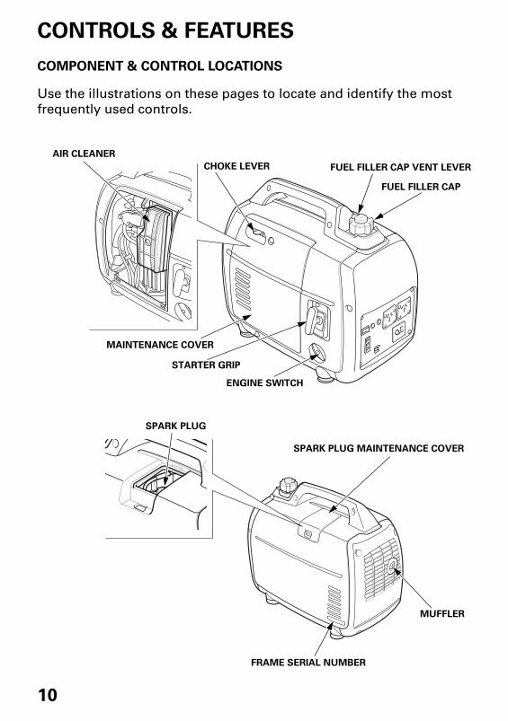
COMPONENT & CONTROL LOCATIONS
Use the illustrations on these pages to locate and identify the most
frequently used controls.
SPARK PLUG MAINTENANCE COVER
MUFFLER
SPARK PLUG
FRAME SERIAL NUMBER
AIR CLEANER
FUEL FILLER CAP VENT LEVER
FUEL FILLER CAP
ENGINE SWITCH
STARTER GRIP
MAINTENANCE COVER
CHOKE LEVER
32Z446000.book Page 10 Friday, February 2, 2018 3:46 PM

11
CONTROLS & FEATURES
ECO THROTTLE SWITCH
PARALLEL OPERATION OUTLETS
AC RECEPTACLES
DC RECEPTACLE
DC CIRCUIT PROTECTOR
GROUND TERMINAL
OUTPUT INDICATOR
OVERLOAD INDICATOR
OIL ALERT INDICATOR
32Z446000.book Page 11 Friday, February 2, 2018 3:46 PM

12
CONTROLS & FEATURES
CONTROLS
Engine Switch
The engine switch controls the ignition system and the fuel valve.
OFF – Stops the engine and closes the fuel valve.
FUEL OFF – Keeps the ignition system ON, and closes only the fuel valve. (see page 26)
ON – Running position; opens the fuel valve and allows the engine to be started.
Starter Grip
Pulling the starter grip operates the recoil starter to start the engine.
Do not allow the starter grip to snap back against the generator. Return it gently to prevent damage to the starter.
ENGINESWITCH
ON
OFF
STARTER GRIP
FUEL OFF
32Z446000.book Page 12 Friday, February 2, 2018 3:46 PM

13
CONTROLS & FEATURES
Fuel Filler Cap Vent Lever
The fuel filler cap is provided with a vent lever to seal the fuel tank.
The vent lever must be in the ON position for the engine to run.
When the engine is not in use, leave the vent lever in the OFF position
to reduce the possibility of fuel leakage. Allow the engine to cool well
before turning the vent lever to the OFF position.
Choke Lever
The choke is used to provide
proper starting mixture when the
engine is cold. It can be opened
and closed by operating the choke
lever manually. Move the choke
lever to the CLOSED position to
enrich the mixture for cold
starting.
FUEL FILLER CAP VENT LEVER
OFF
ON
FUEL FILLER CAP
ONOFF
OPEN
CHOKE LEVER
CLOSED
32Z446000.book Page 13 Friday, February 2, 2018 3:46 PM

14
CONTROLS & FEATURES
Eco Throttle Switch
The Eco Throttle system automatically reduces engine speed when loads are turned off or disconnected. When appliances are turned on or reconnected, the engine returns to the proper speed to power the electrical load.If high electrical loads are connected simultaneously, turn the Eco Throttle switch to the OFF position to reduce voltage changes.When using the DC output, turn the Eco Throttle switch to the OFF position.ON: Recommended to minimize fuel consumption and further reduce
noise levels when less than a full load is applied to the generator.OFF: The Eco Throttle system does not operate.
Parallel Operation Outlets
These outlets are used for connecting both types of the EU22i generator or EU20i generator for parallel operation (see page 31 through 36). A Honda approved receptacle box (optional equipment) is required for parallel operation. This receptacle box can be purchased from an authorized Honda generator dealer.
ECO THROTTLE SWITCH
OFF
ON
PARALLEL OPERATION OUTLETS
32Z446000.book Page 14 Friday, February 2, 2018 3:46 PM

15
CONTROLS & FEATURES
DC Receptacle
The DC receptacle should ONLY be used for charging 12-volt
automotive type batteries. The DC charging output is not regulated.
This means that the charging output does not decrease as the battery
reaches full charge.
Check the battery voltage frequently while charging to prevent
overcharging the battery.
DC Circuit Protector
The DC circuit protector automatically shuts off the DC battery charging circuit when the DC charging circuit is overloaded, when there is a problem with the battery, or when the connections between the battery and the generator are improper. However, the DC circuit protector does not prevent overcharging.
DC RECEPTACLE
OFF
ON
PUSH
DC CIRCUIT PROTECTOR
32Z446000.book Page 15 Friday, February 2, 2018 3:46 PM

16
CONTROLS & FEATURES
FEATURES
Ground Terminal
The generator ground terminal is connected to the frame of the
generator, the metal non-current-carrying parts of the generator, and
the ground terminals of each receptacle.
Before using the ground terminal, consult a qualified electrician,
electrical inspector, or local agency having jurisdiction for local codes
or ordinances that apply to the intended use of the generator.
GROUND TERMINAL
32Z446000.book Page 16 Friday, February 2, 2018 3:46 PM

17
CONTROLS & FEATURES
Output Indicator
The output indicator (green) is illuminated when the generator is
operating normally. It indicates that the generator is producing
electrical power at the receptacles.
In addition, the output indicator has a simplified hour meter function.
When you start the engine, the indicator blinks according to the
generator’s cumulative operating hours as follows:
• No blinks: 0–100 hours
• 1 blink: 100–200 hours
• 2 blinks: 200–300 hours
• 3 blinks: 300–400 hours
• 4 blinks: 400–500 hours
• 5 blinks: 500 or more hours
OUTPUT INDICATOR(GREEN)
32Z446000.book Page 17 Friday, February 2, 2018 3:46 PM
18
CONTROLS & FEATURES
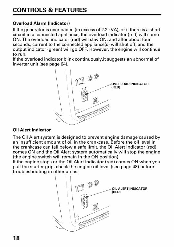
Overload Alarm (Indicator)
If the generator is overloaded (in excess of 2.2 kVA), or if there is a short circuit in a connected appliance, the overload indicator (red) will come ON. The overload indicator (red) will stay ON, and after about four seconds, current to the connected appliance(s) will shut off, and the output indicator (green) will go OFF. However, the engine will continue to run.If the overload indicator blink continuously,it suggests an abnormal of inverter unit (see page 64).
Oil Alert Indicator
The Oil Alert system is designed to prevent engine damage caused by an insufficient amount of oil in the crankcase. Before the oil level in the crankcase can fall below a safe limit, the Oil Alert indicator (red) comes ON and the Oil Alert system automatically will stop the engine (the engine switch will remain in the ON position).If the engine stops or the Oil Alert indicator (red) comes ON when you pull the starter grip, check the engine oil level (see page 48) before troubleshooting in other areas.
OVERLOAD INDICATOR(RED)
OIL ALERT INDICATOR(RED)
32Z446000.book Page 18 Friday, February 2, 2018 3:46 PM

19
CONTROLS & FEATURES
LED Light Patterns
: ON
: OFF
: Blinking
Refer to TAKING CARE OF UNEXPECTED PROBLEMS on page 64 for
failure diagnosis.
Status Possible cause Output Indicator Overload indicator Oil Alert Indicator
Normal Operating
normally
Malfunction Inverter unit
failure
Abnormal Output
overcurrent
Inverter unit
overheat
Warning Engine oil low
OIL ALERT INDICATOR
OVERLOAD INDICATOR
OUTPUT INDICATOR
32Z446000.book Page 19 Friday, February 2, 2018 3:46 PM

20
BEFORE OPERATION
ARE YOU READY TO GET STARTED?
Your safety is your responsibility. A little time spent in preparation will
significantly reduce your risk of injury.
Knowledge
Read and understand this manual. Know what the controls do and how
to operate them.
Familiarize yourself with the generator and its operation before you
begin using it. Know how to quickly shut off the generator in case of
an emergency.
If the generator is being used to power appliances, be sure that they do
not exceed the generator’s load rating (see pages 30 and 36).
IS YOUR GENERATOR READY TO GO?
For your safety, to ensure compliance with environmental regulations,
and to maximize the service life of your equipment, it is very important
to take a few moments before you operate the generator to check its
condition. Be sure to take care of any problem you find, or have your
servicing dealer correct it, before you operate the generator.
Failure to properly maintain this
generator, or failing to correct a
problem before operation, could
result in a significant malfunction.
Some malfunctions can cause
serious injuries or death.
Always perform a pre-operation
inspection before each operation
and correct any problems.
32Z446000.book Page 20 Friday, February 2, 2018 3:46 PM

21
BEFORE OPERATION
To prevent a possible fire, keep the generator at least 1 meter away
from building walls and other equipment during operation. Do not
place flammable objects close to the engine.
Before beginning your pre-operation checks, be sure the generator is
on a level surface and the engine switch is in the OFF position.
Check the Engine
• Before each use, look around and underneath the engine for signs of
oil or gasoline leaks.
• Check the engine oil level (see page 48). A low engine oil level will
cause the Oil Alert system to shut down the engine.
• Check the air filters (see page 51). Dirty air filters will restrict air flow
to the carburetor, reducing engine and generator performance.
• Check the fuel level (see page 46). Starting with a full tank will help
to eliminate or reduce operating interruptions for refueling.
32Z446000.book Page 21 Friday, February 2, 2018 3:46 PM

22
OPERATION
SAFE OPERATING PRECAUTIONS
Before operating the generator for the first time, review chapters
GENERATOR SAFETY (see page 6) and BEFORE OPERATION (see page
20).
For your safety, do not operate the generator in an enclosed area such
as a garage. Your generator’s exhaust contains poisonous carbon
monoxide gas that can collect rapidly in an enclosed area and cause
illness or death.
Before connecting an AC appliance or power cord to the generator:
• Use grounded 3-prong extension cords, tools, and appliances, or
double-insulated tools and appliances.
• Inspect cords and plugs, and replace if damaged.
• Make sure that the appliance is in good working order. Faulty
appliances or power cords can create a potential for electric shock.
• Make sure the electrical rating of the tool or appliance does not
exceed the rated power of the generator or the receptacle being
used.
• Operate the generator at least 1 meter away from buildings and
other equipment.
• Do not operate the generator in an enclosed structure.
• Do not place flammable objects close to the engine or locate the
generator near flammable materials.
Exhaust contains poisonous carbon
monoxide gas that can build up to
dangerous levels in closed areas.
Breathing carbon monoxide can
cause unconsciousness or death.
Never run this product's engine in a
closed, or even partly closed area.
32Z446000.book Page 22 Friday, February 2, 2018 3:46 PM

23
OPERATION
STARTING THE ENGINE
To prevent a possible fire, keep the generator at least 1 meter away from
building walls and other equipment during operation. Do not place
flammable objects close to the engine.
• Operating this generator less than 1 meter from a building or other obstruction can cause overheating and damage the generator.
• For proper cooling, allow at least 1 meter of empty space above and around the generator.Keep all cooling holes open and clear of debris, mud, water, etc. Cooling holes are located on the side panel, the control panel, and the bottom of the generator. If the cooling holes are blocked, the generator may overheat and damage the engine, inverter, or windings.
Refer to SAFE OPERATING PRECAUTIONS on page 22 and perform the
IS YOUR GENERATOR READY TO GO? checks (see page 20).
Refer to the AC OPERATION (see page 28), AC PARALLEL OPERATION
(see page 31) or DC OPERATION (see page 37) for connecting loads to
the generator.
1. Make sure that all appliances are disconnected from the AC receptacle.
2. Turn the fuel filler cap vent lever to the ON position.
FUEL FILLER CAP VENT LEVER
ON
ON
32Z446000.book Page 23 Friday, February 2, 2018 3:46 PM

24
OPERATION
3. Make sure the Eco Throttle
switch is in the OFF position, or
more time will be required for
warm-up.
4. To start a cold engine, move
the choke lever to the CLOSED
position. To restart a warm
engine, leave the choke lever in
the OPEN position.
5. Turn the engine switch to the
ON position.
ECO THROTTLE SWITCH
OFF
CHOKE LEVER
CLOSED
ON
ENGINE SWITCH
32Z446000.book Page 24 Friday, February 2, 2018 3:46 PM

25
OPERATION
6. Pull the starter grip lightly until
you feel resistance; then pull
briskly in the direction of the
arrow as shown.
Do not allow the starter grip to snap back against the generator. Return it gently to prevent damage to the starter.
7. If the choke lever was moved to
the CLOSED position to start
the engine, gradually move it to
the OPEN position as the
engine warms up.
8. If you wish to use the
Eco Throttle system, turn the
Eco Throttle switch to the ON
position after the engine has
warmed up for 2 or 3 minutes.
STARTER GRIP
ECO THROTTLE SWITCH
OPEN
Direction to pull
ON
CHOKE LEVER
32Z446000.book Page 25 Friday, February 2, 2018 3:46 PM

26
OPERATION
STOPPING THE ENGINE
To stop the engine in an emergency, simply turn the engine switch to the OFF position securely. Under normal conditions, use the following procedure.
1. Turn off or disconnect all appliances that are connected to the generator.
2. Turn the engine switch to the OFF position securely.
Operating the generator in the FUEL OFF position before turning the engine switch to the OFF position can reduce the fuel in the carburetor.• When using the FUEL OFF position, the generator will continue to
run for several minutes until the fuel in the carburetor has been consumed, and then the engine will stop.
• Turn the engine switch to the OFF position after the engine stops.• After stopping the engine using the FUEL OFF position, restarting
the engine will require additional pulls on the recoil starter.
3. Allow the engine to cool, and then turn the fuel filler cap vent lever to the OFF position.
ENGINE SWITCH OFF
FUEL OFF
FUEL FILLER CAP VENT LEVER
OFF
OFF
32Z446000.book Page 26 Friday, February 2, 2018 3:46 PM

27
OPERATION
4. If two generators were connected for parallel operation, disconnect
the receptacle box for parallel operation after stopping the engines
if you do not wish to resume parallel operation.
If the generator will not be used for a long period of time, refer to
page 57 for information on Draining the Fuel Tank and Carburetor.
RECEPTACLE BOX FOR PARALLEL OPERATION(optional equipment)
32Z446000.book Page 27 Friday, February 2, 2018 3:46 PM

28
OPERATION
AC OPERATION
Before connecting an appliance to the generator, make sure that it is
in good working order and that its electrical rating does not exceed
that of the generator.
Most motorized appliances require more than their electrical rating for
startup. When an electric motor is started, the overload indicator (red)
may come ON. This is normal if the overload indicator (red) goes OFF
within 4 seconds. If the overload indicator (red) stays ON, consult your
generator dealer.
1. Start the engine (see page 23) and make sure the output indicator
(green) comes ON.
OVERLOAD INDICATOR(RED)
OUTPUT INDICATOR(GREEN)
32Z446000.book Page 28 Friday, February 2, 2018 3:46 PM

29
OPERATION
2. Plug in the appliance into the
receptacle.
3. Turn on the appliance.
If the generator is overloaded (see page 30), or if there is a short
circuit in a connected appliance, the overload indicator (red) will go
ON. The overload indicator (red) will stay ON, and after about four
seconds, current to the connected appliance(s) will shut off, and the
output indicator (green) will go OFF. Stop the engine and investigate
the problem.
Determine if the cause is a short circuit in a connected appliance or an
overload. Correct the problem and restart the generator.
PLUG
32Z446000.book Page 29 Friday, February 2, 2018 3:46 PM

30
OPERATION
AC Applications
Before connecting an appliance or power cord to the generator:
• Make sure that it is in good working order. A faulty appliance or
power cord can create a potential for electrical shock.
• If an appliance begins to operate abnormally, becomes sluggish, or
stops suddenly, turn it off immediately. Disconnect the appliance, and
determine whether the problem is the appliance or the rated load
capacity of the generator has been exceeded.
Most appliance motors require more than their rated wattage for
startup.
Make sure the electrical rating of the tool or appliance does not exceed
the maximum power rating of the generator.
Maximum power is:
2.2 kVA
For continuous operation, do not exceed the rated power.
Rated power is:
1.8 kVA
In either case, the total power requirements (VA) of all appliances
connected must be considered. Appliance and power tool
manufacturers usually list rating information near the model number or
serial number.
Substantial overloading that continuously lights the overload indicator (red) may damage the generator. Marginal overloading that temporarily lights the overload indicator (red) may shorten the service life of the generator.
32Z446000.book Page 30 Friday, February 2, 2018 3:46 PM

31
OPERATION
AC PARALLEL OPERATION (optional equipment)
Both types of EU22i generator can be connected to each other to
increase the available power using a receptacle box.
Before connecting an appliance to either generator, make sure that it
is in good working order and that its electrical rating does not exceed
that of the receptacle.
Most motorized appliances require more than their electrical rating for
startup. When an electric motor is started, the overload indicator (red)
may come ON. This is normal if the overload indicator (red) goes OFF
within 4 seconds. If the overload indicator (red) stays ON, consult your
generator dealer.
During parallel operation, the Eco Throttle switch should be in the
same position on both generators.
1. Install the receptacle box for parallel operation on to the one generator and secure it with setting band as shown.• Set the belt on the front side of the handle.• Secure the narrow belt to the handle with the velcro fastening.• Pass the upper wide belt through the lower belt hook and secure
with the velcro fastening.• Route the receptacle box wires under the engine switch.• Install the belts so they are not slack.
VELCRO FASTENING
ENGINE SWITCH
RECEPTACLE BOX FORPARALLEL OPERATION(optional equipment)
NARROW BELT HANDLE WIDE BELT
VELCRO FASTENING LOWER BELT HOOK
32Z446000.book Page 31 Friday, February 2, 2018 3:46 PM

32
OPERATION
2. Connect the cable connectors and ground terminals of the
receptacle box for parallel operation to the generators and secure
the cord clamp to handle.
• Place two generators at least 1 meter away from each other
during parallel operation.
• Route the wire through the handle and clamp it to the handle
using the band.
• Take care not to slacken the wire toward the starter grip side.
• Connect the longer wire to the generator on which the receptacle
box for parallel operation is not installed.
• Do not set the generators with the exhaust side face to face each
other.
3. Connect the ground terminal of one generator to the ground.
• When an appliance is connected to the ground, connect the
generator to the ground as well.
PARALLEL OPERATION OUTLETS(optional equipment)
GROUNDTERMINAL
BAND
At least 1 m
32Z446000.book Page 32 Friday, February 2, 2018 3:46 PM

33
OPERATION
4. Start the engines and make sure the output indicators (green) come
ON.
5. Confirm that the appliance to be used is switched off, and plug in
the appliance.
6. Switch on the equipment to be used.
If the generators are overloaded (see page 36), or if there is a short
circuit in a connected appliance, the overload indicator (red) will go
ON. The overload indicator (red) will stay ON, and after about four
seconds, current to the connected appliance(s) will shut off, and the
output indicator (green) will go OFF. Stop both engines and
investigate the problem.
Determine if the cause is a short circuit in a connected appliance or an
overload. Correct the problem and restart the generator.
OUTPUT INDICATORLIGHT (GREEN)
PLUG
32Z446000.book Page 33 Friday, February 2, 2018 3:46 PM

34
OPERATION
Parallel operation with EU20i
For instructions on how to connect the parallel operation cable, refer
to pages 31 through 33.
An EU22i generator may only be connected to EU20i generator that
have specific frame serial numbers. Refer to the table below to
confirm that your EU20i generator is compatible with an EU22i.
Model Frame Serial Number Range
EU20iEAAJ -2032188 and later
EACT -1000001 and later
32Z446000.book Page 34 Friday, February 2, 2018 3:46 PM

35
OPERATION
AC Parallel Operation Applications
Before connecting an appliance or power cord to the generator:
• Make sure that it is in good working order. A faulty appliance or
power cord can create a potential for electrical shock.
• If an appliance begins to operate abnormally, becomes sluggish, or
stops suddenly, turn it off immediately. Disconnect the appliance,
and determine whether the problem is the appliance or the rated
load capacity of the generator has been exceeded.
• Never connect other than the specified generator models
(see page 7).
• For parallel operation, use only a Honda approved receptacle box
(optional equipment).
• Never connect or remove the receptacle box when the generator is
running.
• For single generator operation, the receptacle box for parallel
operation must be removed.
32Z446000.book Page 35 Friday, February 2, 2018 3:46 PM

36
OPERATION
Most appliance motors require more than their rated wattage for
startup.
Make sure the electrical rating of the tool or appliance does not
exceed the maximum power rating of the generator.
Maximum power in parallel operation is:
For continuous operation, do not exceed the rated power.
Rated power in parallel operation is:
In either case, the total power requirements (VA) of all appliances
connected must be considered. Appliance and power tool
manufacturers usually list rating information near the model number
or serial number.
Substantial overloading that continuously lights the overload indicator (red) may damage the generator. Marginal overloading that temporarily lights the overload indicator (red) may shorten the service life of the generator.
EU22i and EU22i 4.4kVA
EU22i and EU20i 4.2kVA
EU22i and EU22i 3.6kVA
EU22i and EU20i 3.4kVA
32Z446000.book Page 36 Friday, February 2, 2018 3:46 PM

37
OPERATION
DC OPERATION
The DC receptacle should ONLY be used for charging 12-volt
automotive type batteries. The DC charging output is not regulated.
This means that the charging output is constant; it does not decrease
as the battery reaches full charge. Check the battery voltage frequently
while charging to prevent overcharging the battery.
When using the DC output, turn the Eco Throttle switch to the OFF
position.
Connecting the battery charging cable (optional equipment):
1. Before connecting the battery charging cable to a battery that is
installed in a vehicle, disconnect the vehicle battery ground cable
from the negative (–) battery terminal.
WARNING: Battery posts, terminals, and related accessories contain
lead and lead components. Wash hands after handling.
2. Plug the battery charging cable into the DC receptacle of the
generator.
The battery gives off explosive
hydrogen gas during normal
operation.
A spark or flame can cause the
battery to explode with enough
force to kill or seriously hurt you.
Wear protective clothing and a face
shield, or have a skilled mechanic
perform the battery maintenance.
32Z446000.book Page 37 Friday, February 2, 2018 3:46 PM

38
OPERATION
3. Connect the red lead of the battery charging cable to the positive (+)
battery terminal and the black lead to the negative (–) battery
terminal.
4. Start the generator (see page 23).
Do not start the vehicle while the battery charging cable is connected and the generator is running. The vehicle or the generator may be damaged.
An overloaded DC circuit, excessive current draw by the battery, or a
wiring problem will trip the DC circuit protector (PUSH button extends
out). If this happens, wait a few minutes before pushing in the circuit
protector to resume operation. If the DC circuit protector continues to
go OFF, discontinue charging and see your authorized Honda
generator dealer. The circuit protector does not prevent overcharging
the battery.
BATTERY CHARGING CABLE(Optional equipment)
BLACK LEAD
RED LEAD
DC CIRCUITPROTECTOR
PUSH
OFF
ON
YELLOW INDICATOR
DC RECEPTACLE
32Z446000.book Page 38 Friday, February 2, 2018 3:46 PM

39
OPERATION
Disconnecting the battery charging cable:
1. Stop the engine.
2. Disconnect the black lead of the battery charging cable from the
negative (–) battery terminal.
3. Disconnect the red lead of the battery charging cable from the
positive (+) battery terminal.
4. Disconnect the battery charging cable from the DC receptacle of the
generator.
5. Connect the vehicle battery ground cable to the negative (–) battery
terminal.
BATTERY CHARGING CABLE(optional equipment)
BLACK LEAD
RED LEAD
32Z446000.book Page 39 Friday, February 2, 2018 3:46 PM

40
OPERATION
ECO THROTTLE SYSTEM
With the switch in the ON position, engine speed is automatically
lowered when loads are reduced, turned off, or disconnected. When
appliances are turned on or reconnected, the engine returns to the
proper speed to power the electrical load. In the OFF position, the
Eco Throttle system does not operate.
Appliances with large start-up power demands may not allow the
engine to reach normal operating rpm when they are connected to the
generator. Turn the Eco Throttle switch to the OFF position and connect
the appliance to the generator. If the engine still will not reach normal
operating speed, check that the appliance does not exceed the rated
load capacity of the generator.
If high electrical loads are connected simultaneously, turn the
Eco Throttle switch to the OFF position to reduce voltage changes.
The Eco Throttle system is not effective for use with appliances or tools
that require only momentary power. If the tool or appliance will be
turned ON and OFF quickly, the Eco Throttle switch should be in the
OFF position.
When using the DC output, turn the Eco Throttle switch to the OFF
position.
ECO THROTTLE SWITCH
OFF
ON
32Z446000.book Page 40 Friday, February 2, 2018 3:46 PM

41
OPERATION
STANDBY POWER
Connections to a Building’s Electrical System
Connections for standby power to a building’s electrical system must
be made by a qualified electrician. The connection must isolate the
generator power from utility power, and must comply with all
applicable laws and electrical codes.
In some areas, generators are required by law to be registered with
local utility companies. Check local regulations for proper registration
and use procedures.
System Ground
This generator has a system ground that connects generator frame
components to ground terminals in the AC output receptacles. The
system ground is not connected to the AC neutral wire.
Improper connections to a building’s
electrical system can allow current
from the generator to backfeed into
the utility lines.
Such backfeed may electrocute
utility company workers or others
who contact the lines during a
power outage, and the generator
may explode, burn, or cause fires
when utility power is restored.
Consult the utility company or a
qualified electrician prior to making
any power connections.
32Z446000.book Page 41 Friday, February 2, 2018 3:46 PM

42
OPERATION
Special Requirements
Do not lay the generator on its side when moving, storing, or operating it. Oil may leak and damage the engine or your property.
There may be applicable laws, local codes, or ordinances that apply to
the intended use of the generator. Please consult a qualified
electrician, electrical inspector, or the local agency having jurisdiction.
• In some areas, generators are required to be registered with local
utility companies.
• If the generator is used at a construction site, there may be
additional regulations that must be observed.
32Z446000.book Page 42 Friday, February 2, 2018 3:46 PM

43
SERVICING YOUR GENERATOR
THE IMPORTANCE OF MAINTENANCE
Good maintenance is essential for safe, economical, and trouble free
operation. It will also help reduce air pollution.
To help you properly care for your generator, the following pages
include a maintenance schedule, routine inspection procedures, and
simple maintenance procedures using basic hand tools. Other service
tasks that are more difficult or require special tools are best handled by
professionals and are normally performed by a Honda technician or
other qualified mechanic.
The maintenance schedule applies to normal operating conditions. If
you operate your generator under unusual conditions, such as
sustained high-load or high-temperature operation, or use it in dusty
conditions, consult your servicing dealer for recommendations
applicable to your individual needs and use.
Remember that an authorized Honda servicing dealer knows your
generator best and is fully equipped to maintain and repair it.
To ensure the best quality and reliability, use only new, Honda Genuine
parts or their equivalents for repair and replacement.
Failure to properly maintain this
generator, or failing to correct a
problem before operation, could
result in a significant malfunction.
Some malfunctions can cause
serious injuries or death.
Always follow the inspection and
maintenance recommendations and
schedules in this owner's manual.
32Z446000.book Page 43 Friday, February 2, 2018 3:46 PM

44
SERVICING YOUR GENERATOR
MAINTENANCE SAFETY
Some of the most important safety precautions follow. However, we
cannot warn you of every conceivable hazard that can arise in
performing maintenance. Only you can decide whether or not you
should perform a given task.
Safety Precautions
Make sure the engine is off before you begin any maintenance or
repairs. This will eliminate several potential hazards:
– Carbon monoxide poisoning from engine exhaust.
Operate outside away from open windows or doors.
– Burns from hot parts.
Let the engine and exhaust system cool before touching.
– Injury from moving parts.
Do not run the engine unless instructed to do so.
• Read the instructions before you begin, and make sure you have the
tools and skills required.
• To reduce the possibility of fire or explosion, be careful when
working around gasoline. Use only a non-flammable solvent, not
gasoline, to clean parts. Keep cigarettes, sparks, and flames away
from all fuel-related parts.
Improper maintenance can cause
an unsafe condition.
Failure to properly follow
maintenance instructions and
precautions can cause serious
injuries or death.
Always follow the procedures and
precautions in this owner's manual.
32Z446000.book Page 44 Friday, February 2, 2018 3:46 PM

45
SERVICING YOUR GENERATOR
MAINTENANCE SCHEDULE
(1) Service more frequently when used in dusty areas.
(2) These items should be serviced by your servicing dealer, unless you have the proper tools
and are mechanically proficient. Refer to the Honda shop manual for service procedures.
(3) For commercial use, log hours of operation to determine proper maintenance intervals.
REGULAR SERVICE PERIOD (3)
Perform at every indicated month
or operating hour interval,
whichever comes first.
ITEM
Each
use
First
month
or
20 Hrs.
Every
3
months
or
50 Hrs.
Every
6
months
or
100 Hrs.
Every
year
or
200 Hrs.Page
Engine oil Check level o 48
Change o o 49
Air cleaner Check o 51
Clean o (1) 53
Spark plug Check-adjust o 54
Replace o 54
Valve clearance Check-adjust o (2) —
Combustion chamber Clean After every 300 hrs. (2) —
Fuel tank and filter Clean o (2) —
Fuel tube Check Every 2 years (Replace if necessary) (2) —
32Z446000.book Page 45 Friday, February 2, 2018 3:46 PM

46
SERVICING YOUR GENERATOR
REFUELING
With the engine stopped, remove the fuel filler cap and check the fuel
level. Refill the fuel tank if the fuel level is low.
Fuel can damage paint and plastic. Be careful not to spill fuel when filling your fuel tank. Damage caused by spilled fuel is not covered under warranty.
Refuel in a well-ventilated area before starting the engine. If the engine
has been running, allow it to cool. Refuel carefully to avoid spilling fuel.
Do not fill the fuel tank above the upper level mark (see page 47) on the
fuel filter.
Never refuel the engine inside a building where gasoline fumes may
reach flames or sparks. Keep gasoline away from appliance pilot lights,
barbecues, electric appliances, power tools, etc.
Spilled fuel is not only a fire hazard, it causes environmental damage.
Wipe up spills immediately.
Gasoline is highly flammable and
explosive.
You can be burned or seriously
injured when handling fuel.
• Stop the engine and let it cool
before handling fuel.
• Keep heat, sparks, and flame away.
• Handle fuel only outdoors.
• Wipe up spills immediately.
32Z446000.book Page 46 Friday, February 2, 2018 3:46 PM

47
SERVICING YOUR GENERATOR
After refueling, tighten the fuel filler cap securely.
FUEL RECOMMENDATIONS
This engine is certified to operate on regular unleaded gasoline with a
research octane rating of 91 or higher (a pump octane rating of 86 or
higher).
Never use gasoline that is stale, contaminated, or mixed with oil.
Avoid getting dirt or water in the fuel tank.
You may use regular unleaded gasoline containing no more than 10%
ethanol (E10) or 5% methanol by volume. In addition, methanol must
contain cosolvents and corrosion inhibitors.
Use of fuels with content of ethanol or methanol greater than shown
above may cause starting and/or performance problems. It may also
damage metal, rubber, and plastic parts of the fuel system.
Engine damage or performance problems that result from using a fuel
with percentages of ethanol or methanol greater than shown above are
not covered under warranty.
If your equipment will be used on an infrequent basis, please refer to
the fuel section of the STORAGE chapter (see page 56) for additional
information regarding fuel deterioration.
FUEL FILLER CAP UPPER LEVEL MARK (RED)
FUEL FILTER
32Z446000.book Page 47 Friday, February 2, 2018 3:46 PM

48
SERVICING YOUR GENERATOR
ENGINE OIL LEVEL CHECK
Check the engine oil level with the generator on a level surface and
the engine stopped.
1. Loosen the maintenance cover screw and remove the maintenance
cover.
2. Remove the oil filler cap and wipe the dipstick clean.
3. Check the oil level by inserting the dipstick into the oil filler neck
without screwing it in.
4. If the level is low, fill to the upper limit of the oil filler neck with the
recommended oil (see page 50).
5. Reinstall the oil filler cap securely.
6. Reinstall the maintenance cover and tighten the maintenance cover
screw securely.
The Oil Alert system will automatically stop the engine before the oil
level falls below safe limits. However, to avoid the inconvenience of an
unexpected shutdown, check the oil level regularly.
MAINTENANCE COVER SCREW
MAINTENANCECOVER
OIL FILLER NECK
UPPER LIMIT
OIL FILLER CAP LOWER LIMIT
32Z446000.book Page 48 Friday, February 2, 2018 3:46 PM

49
SERVICING YOUR GENERATOR
ENGINE OIL CHANGE
Drain the oil while the engine is warm to assure rapid and complete
draining.
1. Turn the engine switch and fuel filler cap vent lever to the OFF
position (see page 26) to reduce the possibility of fuel leakage.
2. Loosen the maintenance cover screw and remove the maintenance
cover (see page 48).
3. Place a suitable container next to the engine to catch the used oil.
4. Remove the oil filler cap, and drain the oil into the container by
tipping the engine toward the oil filler neck.
Improper disposal of engine oil can be harmful to the environment. If you change your own oil, please dispose of the used oil properly. Put it in a sealed container, and take it to a recycling center. Do not discard it in a trash bin, dump it on the ground, or pour it down the drain.
5. With the engine in a level position, fill with the recommended oil
(see page 50) to the upper limit of the oil filler neck.
Maximum oil capacity: 0.44 L
6. Reinstall the oil filler cap securely.
7. Reinstall the maintenance cover and tighten the maintenance cover
screw securely.
Wash your hands with soap and water after handling used oil.
OIL FILLER NECK
UPPER LIMIT
LOWER LIMIT
32Z446000.book Page 49 Friday, February 2, 2018 3:46 PM
50
SERVICING YOUR GENERATOR
ENGINE OIL RECOMMENDATIONS
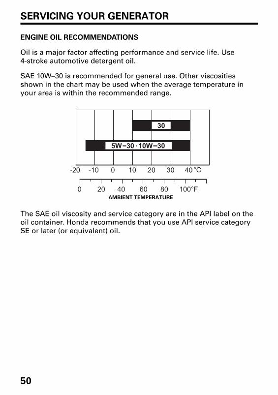
Oil is a major factor affecting performance and service life. Use
4-stroke automotive detergent oil.
SAE 10W–30 is recommended for general use. Other viscosities
shown in the chart may be used when the average temperature in
your area is within the recommended range.
The SAE oil viscosity and service category are in the API label on the
oil container. Honda recommends that you use API service category
SE or later (or equivalent) oil.
AMBIENT TEMPERATURE
32Z446000.book Page 50 Friday, February 2, 2018 3:46 PM

51
SERVICING YOUR GENERATOR
AIR CLEANER SERVICE
1. Loosen the maintenance
cover screw and remove the
maintenance cover.
2. Loosen the air cleaner cover
screw, and remove the air
cleaner cover.
3. Remove the main and outer
filters from the air cleaner housing.
4. Check the main and outer filters to be sure they are clean and in
good condition. If the main and outer filters are dirty, clean them as
described on page 53. Replace the main and outer filters if they are
damaged.
MAIN FILTER
MAINTENANCE COVER SCREW
MAINTENANCE COVER
AIR CLEANERCOVER SCREW
OUTER FILTER
AIR CLEANER COVER
32Z446000.book Page 51 Friday, February 2, 2018 3:46 PM

52
SERVICING YOUR GENERATOR
5. Reinstall the air filters.
6. Make sure that the rubber seal is
set in the groove of the air
cleaner cover.
7. Reinstall the air cleaner cover,
and tighten the air cleaner cover
screw.
8. Reinstall the maintenance cover,
and tighten the maintenance
cover screw securely.
Operating the engine without the air filters or with a damaged air filter will allow dirt to enter the engine, causing rapid engine wear. This type of damage is not covered by the warranty.
AIR CLEANER COVER
RUBBER SEAL
AIR FILTERS
AIR CLEANERCOVER SCREW
AIR CLEANERCOVER
32Z446000.book Page 52 Friday, February 2, 2018 3:46 PM

53
SERVICING YOUR GENERATOR
MAIN AND OUTER FILTER CLEANING
Dirty air filters will restrict air flow to the carburetor, reducing engine
performance. If you operate the generator in very dusty areas, clean
the main and outer filters more frequently than specified in the
Maintenance Schedule.
1. Clean the air filters in warm soapy water, rinse, and allow to dry
thoroughly, or clean in nonflammable solvent and allow to dry.
2. Dip the air cleaner element in clean engine oil, and then squeeze out
all excess oil. The engine will smoke when started if too much oil is
left in the air filters.
3. Wipe dirt from the air cleaner housing and cover using a moist rag.
Be careful to prevent dirt from entering the air duct that leads to the
carburetor.
Clean Squeeze and dry Dip in oil Squeeze
Do not twist. Do not twist.
32Z446000.book Page 53 Friday, February 2, 2018 3:46 PM

54
SERVICING YOUR GENERATOR
SPARK PLUG SERVICE
Spark plug: CR5HSB (NGK)
To ensure proper engine operation, the spark plug must be properly
gapped and free of deposits.
An incorrect spark plug can cause engine damage.
If the engine is hot, allow it to cool before servicing the spark plug.
1. Remove the spark plug maintenance cover.
2. Remove the spark plug cap.
3. Clean any dirt from around the spark plug base.
4. Use a spark plug wrench to remove the spark plug.
SPARK PLUGMAINTENANCECOVER
SPARK PLUG CAP
SPARK PLUG WRENCH
SPARK PLUG CAP
32Z446000.book Page 54 Friday, February 2, 2018 3:46 PM

55
SERVICING YOUR GENERATOR
5. Inspect the spark plug. Replace it
if the electrodes are worn or if
the insulator is cracked, chipped,
or fouled.
6. Measure the spark plug
electrode gap with a wire-type
feeler gauge. Correct the gap, if
necessary, by carefully bending
the side electrode.
The gap should be:
0.6–0.7 mm
7. Make sure that the spark plug sealing washer is in good condition,
and thread the spark plug in by hand to prevent cross-threading.
8. After the spark plug is seated, tighten with a spark plug wrench to
compress the sealing washer.
If reinstalling a used spark plug, tighten 1/8–1/4 turn after the spark
plug seats.
If installing a new spark plug, tighten 1/2 turn after the spark plug
seats.
TORQUE: 12 N·m, 1.2 kgf·m
A loose spark plug can overheat and damage the engine.Overtightening the spark plug can damage the threads in the cylinder head.
9. Reinstall the spark plug cap on the spark plug securely.
10. Reinstall the spark plug maintenance cover.
SIDE ELECTRODE
SEALING WASHER
0.6–0.7 mm
INSULATOR
32Z446000.book Page 55 Friday, February 2, 2018 3:46 PM

56
STORAGE
STORAGE PREPARATION
Proper storage preparation is essential for keeping your generator
trouble-free and looking good. The following steps will help to keep
rust and corrosion from impairing your generator’s function and
appearance, and will make the engine easier to start when you use the
generator again.
Cleaning
Wipe the generator with a moist cloth. After the generator has dried,
touch up any damaged paint, and coat other areas that may rust with
a light film of oil.
Fuel
Depending on the region where you operate your equipment, fuel formulations may deteriorate and oxidize rapidly. Fuel deterioration and oxidation can occur in as little as 30 days and may cause damage to the carburetor and/or fuel system. Please check with your servicing dealer for local storage recommendations.
Gasoline will oxidize and deteriorate in storage. Old gasoline will
cause hard starting, and it leaves gum deposits that clog the fuel
system. If the gasoline in your generator deteriorates during storage,
you may need to have the carburetor and other fuel system
components serviced or replaced.
The length of time that gasoline can be left in your fuel tank and
carburetor without causing functional problems will vary with such
factors as gasoline blend, your storage temperatures, and whether the
fuel tank is partially or completely filled. The air in a partially filled fuel
tank promotes fuel deterioration. Very warm storage temperatures
accelerate fuel deterioration. Fuel deterioration problems may occur
within a few months, or even less if the gasoline was not fresh when
you filled the fuel tank.
32Z446000.book Page 56 Friday, February 2, 2018 3:46 PM

57
STORAGE
Draining the Fuel Tank and Carburetor
1. Unscrew the fuel filler cap (see page 47), remove the fuel filter, and empty the fuel tank into an approved gasoline container. We recommend using a commercially available gasoline hand pump to empty the tank. Do not use an electric pump. Reinstall the fuel filter and the fuel filler cap.
2. Loosen the maintenance cover screw and remove the maintenance cover (see page 48).
Gasoline is highly flammable and explosive.
You can be burned or seriously injured when handling fuel.
• Stop the engine and let it cool before handling fuel.
• Keep heat, sparks, and flame away.• Handle fuel only outdoors.• Wipe up spills immediately.
FUEL FILTER
FUEL FILLER CAP
MAINTENANCE COVER SCREW
MAINTENANCE COVER
32Z446000.book Page 57 Friday, February 2, 2018 3:46 PM

58
STORAGE
3. Loosen the carburetor drain screw, and drain the gasoline from the carburetor into a suitable container.
4. Remove the spark plug maintenance cover and the spark plug cap (see page 54).
5. Turn the engine switch to the ON position.6. Pull the starter grip 3 to 4 times to drain the gasoline from the fuel
pump into a suitable container.7. Turn the engine switch to the OFF position securely.
8. Tighten the carburetor drain screw, and then reinstall the maintenance cover.
9. Reinstall the spark plug cap and spark plug maintenance cover.
CARBURETOR DRAIN SCREW
ENGINE SWITCH OFF
FUEL OFF
32Z446000.book Page 58 Friday, February 2, 2018 3:46 PM

59
STORAGE
Engine Oil
Change the engine oil (see page 49).
Engine Cylinder
1. Remove the spark plug (see page 54), and pour approximately one
teaspoon (5 cc) of clean engine oil into the cylinder. Crank the engine
several revolutions to distribute the oil, then reinstall the spark plug.
2. Reinstall the spark plug cap on the spark plug securely.
3. Reinstall the spark plug maintenance cover.
4. Reinstall the maintenance cover and tighten the maintenance cover
screw securely.
5. Pull the starter grip (see page 25) slowly until you feel resistance,
then return the starter grip gently. This closes the valves so moisture
cannot enter.
32Z446000.book Page 59 Friday, February 2, 2018 3:46 PM

60
STORAGE
STORAGE PRECAUTIONS
If your generator will be stored with gasoline in the fuel tank and
carburetor, it is important to reduce the hazard of gasoline vapor
ignition.
Select a well-ventilated storage area away from any appliance that
operates with a flame, such as a furnace, water heater, or clothes
dryer.
Also, avoid any area with a spark-producing electric motor, or where
power tools are operated.
If possible, avoid storage areas with high humidity, because that
promotes rust and corrosion.
Unless all fuel has been drained from the fuel tank, leave the engine
switch in the OFF position, and the fuel filler cap vent lever in the OFF
position (see page 26) to reduce the possibility of leakage.
Place the generator on a level surface. Tilting or laying it on its side can
cause fuel or oil leakage.
With the engine and exhaust system cool, cover the generator to keep
out dust. A hot engine and exhaust system can ignite or melt some
materials.
Do not use a plastic sheet as a dust cover. A nonporous cover will trap
moisture around the generator, promoting rust and corrosion.
REMOVAL FROM STORAGE
Check your generator as described in the BEFORE OPERATION chapter
of this manual (see page 20).
If the fuel was drained during storage preparation, fill the tank with
fresh gasoline. If you keep a container of gasoline for refueling, be sure
that it contains only fresh gasoline. Gasoline oxidizes and deteriorates
over time, causing hard starting.
If the cylinder was coated with oil during storage preparation, the
engine may smoke briefly at startup. This is normal.
32Z446000.book Page 60 Friday, February 2, 2018 3:46 PM

61
TRANSPORTING
Do not lay the generator on its side when moving, storing, or operating it. Oil may leak and damage the engine or your property.
If the generator has been used, allow it cool for at least 15 minutes
before loading the generator on the transport vehicle. A hot engine and
exhaust system can burn you and can ignite some material.
To prevent fuel spillage when transporting, the generator should be
secured upright in its normal operating position, with the engine switch
OFF and the fuel filler cap vent lever turned fully counterclockwise to
the OFF position (see page 26).
Take care not to drop or strike the generator when transporting. Do
not place heavy objects on the generator.
32Z446000.book Page 61 Friday, February 2, 2018 3:46 PM

62
TAKING CARE OF UNEXPECTED PROBLEMS
ENGINE WILL NOT START
Possible Cause Correction
Fuel filler cap vent lever is in the
OFF position.
Turn the vent lever to the ON
position (see page 23).
Engine switch is in the OFF
position.
Turn engine switch to the ON
position (see page 24).
Out of fuel. Refuel (see page 46).
Bad fuel; generator stored
without treating or draining
gasoline, or refueled with bad
gasoline.
Drain fuel tank and carburetor
(see page 57).
Refuel with fresh gasoline
(see page 46).
Low engine oil level caused Oil
Alert to stop engine.
Turn the engine switch to the OFF
position. Add engine oil. Then
turn the engine switch to the ON
position and restart the engine.
Spark plug faulty, fouled, or
improperly gapped.
Gap or replace spark plug
(see page 54).
Spark plug wet with fuel
(flooded engine).
Dry and reinstall spark plug.
Fuel filter restricted, carburetor
malfunction, ignition
malfunction, valves stuck, etc.
Take the generator to an
authorized Honda servicing
dealer, or refer to the shop
manual.
32Z446000.book Page 62 Friday, February 2, 2018 3:46 PM

63
TAKING CARE OF UNEXPECTED PROBLEMS
ENGINE LACKS POWER
Possible Cause Correction
Air filter restricted. Clean or replace air filter (see
page 51).
Bad fuel; generator stored
without treating or draining
gasoline, or refueled with bad
gasoline.
Drain fuel tank and carburetor
(see page 57).
Refuel with fresh gasoline
(see page 46).
Fuel filter restricted, carburetor
malfunction, ignition
malfunction, valves stuck, etc.
Take the generator to an
authorized Honda servicing
dealer, or refer to the shop
manual.
32Z446000.book Page 63 Friday, February 2, 2018 3:46 PM

64
TAKING CARE OF UNEXPECTED PROBLEMS
NO POWER AT THE AC RECEPTACLES
NO POWER AT THE DC RECEPTACLES
Possible Cause Correction
Output indicator is OFF, and
overload indicator is ON.
Check AC load. Stop and restart
the engine.
Check the cooling air inlet. Stop
and restart the engine.
Overload indicator blink. Take the generator to an
authorized Honda servicing
dealer, or refer to the shop
manual.
Faulty power tool or appliance. Replace or repair power tool or
appliance.
Stop and restart the engine.
Faulty generator. Take the generator to an
authorized Honda servicing
dealer, or refer to the shop
manual.
Possible Cause Correction
DC circuit protector OFF. Turn DC circuit protector ON
(see page 38).
Faulty generator. Take the generator to an
authorized Honda servicing
dealer, or refer to the shop
manual.
32Z446000.book Page 64 Friday, February 2, 2018 3:46 PM

65
TECHNICAL INFORMATION
Serial Number Location
Record the frame serial number and date purchased in the spaces
below. You will need this information when ordering parts and when
making technical or warranty inquiries.
Frame serial number:
Date purchased:
FRAME SERIAL NUMBER
32Z446000.book Page 65 Friday, February 2, 2018 3:46 PM

66
TECHNICAL INFORMATION
Carburetor Modification for High Altitude Operation
At high altitude, the standard carburetor air-fuel mixture will be too
rich. Performance will decrease, and fuel consumption will increase. A
very rich mixture will also foul the spark plug and cause hard starting.
Operation at an altitude that differs from that at which this engine was
certified, for extended periods of time, may increase emissions.
High altitude performance can be improved by specific modifications
to the carburetor. If you always operate your generator at altitudes
above 1,500 meters, have your authorized Honda servicing dealer
perform this carburetor modification. This engine, when operated at
high altitude with the carburetor modifications for high altitude use,
will meet each emission standard throughout its useful life.
Even with carburetor modification, engine horsepower will decrease
about 3.5% for each 300-meter increase in altitude. The effect of
altitude on horsepower will be greater than this if no carburetor
modification is made.
When the carburetor has been modified for high altitude operation, the air/fuel mixture will be too lean for low altitude use. Operation at altitudes below 1,500 meters with a modified carburetor may cause the engine to overheat and result in serious engine damage. For use at low altitudes, have your servicing dealer return the carburetor to original factory specifications.
32Z446000.book Page 66 Friday, February 2, 2018 3:46 PM

67
TECHNICAL INFORMATION
Specifications
Dimensions
Engine
Generator
Tune-up Specifications
Specifications are subject to change without notice.
Model EU22iT
Description code EAMT
Length 509 mm
Width 290 mm
Height 425 mm
Dry mass [weight] 21.1 kg
Model GXR120T
Engine type 4-stroke, overhead camshaft, single cylinder
Displacement[Bore × Stroke]
121 cm3
[60.0 × 43.0 mm]
Compression ratio 8.5:1
Engine speed 4,000 – 4,500 rpm (with Eco Throttle switch OFF)
Cooling system Forced air
Ignition system Full transistor
Engine oil capacity 0.44 L
Fuel tank capacity 3.6 L
Spark plug CR5HSB (NGK)
Model EU22iT
Type U4
AC output
Rated voltage (V) 240
Rated frequency (Hz) 50
Rated current (A) 7.5
Rated output (kVA) 1.8
Maximum output (kVA) 2.2
DC output Only for charging 12 V automotive batteries.Maximum charging output = 8.3 A
ITEM SPECIFICATION MAINTENANCE
Spark plug gap 0.6 – 0.7 mm Refer to page 54.
Valve clearance (cold)
IN: 0.15 ± 0.04 mmEX: 0.20 ± 0.04 mm
See your authorizedHonda dealer.
Other specifications No other adjustments needed.
32Z446000.book Page 67 Friday, February 2, 2018 3:46 PM

68
TECHNICAL INFORMATION
WIRING DIAGRAM
ACOR
Cot
CPB
DC, CP
DC, D
DCOR
DC, W
EcoSw
EgB
EgG
ESw
ExW
FrB
FrG
GeB
GT
IB
FTU
IgC
IU
MW
NF
OAL
OAU
OI
OLSw
PC
PL
RBx
SP
SpU
StpM
SW
AC Output Receptacle
Parallel operation socket
Control Panel Block
DC Circuit Protector
DC Diode
DC Output Receptacle
DC Winding
Eco throttle switch
Engine Block
Engine Ground
Engine Switch
Exciter Winding
Frame Block
Frame Ground
Generator Block
Ground Terminal
Inverter Block
Full-Transistor Unit
Ignition Coil
Inverter Unit
Main Winding
Noise Filter(DC)
Oil Alert Indicator
Oil Alert Unit
Overload Indicator
Oil Level Switch
Pulser Coil
Output Indicator
Receptacle Box for
Parallel Operation
Spark Plug
Spark Unit
Stepping Motor
(Throttle Control)
Sub Winding
Bl
Y
Bu
G
R
W
Br
Lg
Gr
Lb
O
P
BLACK
YELLOW
BLUE
GREEN
RED
WHITE
BROWN
LIGHT GREEN
GRAY
LIGHT BLUE
ORANGE
PINK
ENGINE SWITCH
ECO THROTTLE SWITCH
G BIOFF o o
ON
R/W R/YONOFF o o
32Z446000.book Page 68 Friday, February 2, 2018 3:46 PM

69
TECHNICAL INFORMATION
RM
W
SW
IU
DC
, W
ExW
SP
IgC
EgG
EgG
PC
Stp
M
DC
, D
ES
w
OLS
w
W Bu
WRY
Bu
WRY
Bu
Bl
Y/G
Y/G EgG
Y/G
Y
Y/G
Y/G
Y/G
Y/G
Bu
Br
Br
Br
Bl/B
u
Br
W/R
Bl/RBl/R
W/R
Bl/R
W/R
Bu
Bu
Bl/B
uB
l/Bu
Y/G
Y/G
YY
Bl
Bl/R
W/R
Y/G
Y/G
Y/G
Bl
Y/G
Bl
GB
lG
R/W
G/R
G/B
l
PL
Ol
Y Y/G Bl
Bl/B
uB
u
R/W
R/Y
R/WWBr
Br
Br
R/Y
WW
G/R
G/B
l
EgB
FrB
CP
B
IBG
eB
DC
OR
NF
DC
, CP
FrG
SpU
Eco
Sw
OA
L
FT
U
OA
U
P Gr
P Gr
AC
OR
AC
OR
Br
W
Y/G
Y/G
Y/G
W
R
B
B B
B B
RB
x
GT
32Z446000.book Page 69 Friday, February 2, 2018 3:46 PM

70
CONSUMER INFORMATION
Australia Distributor Information
NAME OF FIRM
(COMPANY)ADDRESS TEL: FAX:
Honda Australia
Motorcycle and Power
Equipment Pty. Ltd.
1954-1956 Hume
Highway Campbellfield
Victoria 3061
Tel: (03) 9270 1111
Fax: (03) 9270 1133
32Z446000.book Page 70 Friday, February 2, 2018 3:46 PM

71
MEMO
32Z446000.book Page 71 Friday, February 2, 2018 3:46 PM

72
MEMO
32Z446000.book Page 72 Friday, February 2, 2018 3:46 PM