generator arbitrary waveform k e y s ig h t m8195 a m8195a... · safety summary general safety...
TRANSCRIPT

User’s Guide
Keysight M8195A Arbitrary Waveform Generator


Notices © Keysight Technologies, Inc. 2014
No part of this manual may be
reproduced in any form or by any
means (including electronic storage
and retrieval or translation into a
foreign language) without prior
agreement and written consent from
Keysight Technologies, Inc. as
governed by United States and
international copyright laws.
Manual Part Number
M8195-91020
Edition
Second edition, October 2014
Keysight Technologies,
Deutschland GmbH
Herrenberger Str. 130
71034 Böblingen, Germany
For Assistance and Support
http://www.keysight.com/find/assist
Limitation of Warranty
The foregoing warranty shall not
apply to defects resulting from
improper or inadequate maintenance
by Buyer, Buyer-supplied software or
interfacing, unauthorized modification
or misuse, operation outside of the
environmental specifications for the
product, or improper site preparation
or maintenance. No other warranty is
expressed or implied. Keysight
Technologies specifically disclaims
the implied warranties of
Merchantability and Fitness for a
Particular Purpose.
ESD sensitive device
All front-panel connectors of the
M8195A are sensitive to Electrostatic
discharge (ESD). We recommend to
operate the instrument in an
electrostatic safe environment.
There is a risk of instrument
malfunction when touching a
connector.
Please follow this instruction:
Before touching the front-panel
connectors, discharge yourself by
touching the properly grounded
mainframe.
Warranty
THE MATERIAL CONTAINED IN THIS
DOCUMENT IS PROVIDED “AS IS,”
AND IS SUBJECT TO BEING
CHANGED, WITHOUT NOTICE, IN
FUTURE EDITIONS. FURTHER, TO
THE MAXIMUM EXTENT PERMITTED
BY APPLICABLE LAW, KEYSIGHT
DISCLAIMS ALL WARRANTIES,
EITHER EXPRESS OR IMPLIED, WITH
REGARD TO THIS MANUAL AND ANY
INFORMATION CONTAINED HEREIN,
INCLUDING BUT NOT LIMITED TO
THE IMPLIED WARRANTIES OF
MERCHANTABILITY AND FITNESS
FOR A PARTICULAR PURPOSE.
KEYSIGHT SHALL NOT BE LIABLE
FOR ERRORS OR FOR INCIDENTAL
OR CONSEQUENTIAL DAMAGES IN
CONNECTION WITH THE
FURNISHING, USE, OR
PERFORMANCE OF THIS DOCUMENT
OR OF ANY INFORMATION
CONTAINED HEREIN. SHOULD
KEYSIGHT AND THE USER HAVE A
SEPARATE WRITTEN AGREEMENT
WITH WARRANTY TERMS COVERING
THE MATERIAL IN THIS DOCUMENT
THAT CONFLICT WITH THESE
TERMS, THE WARRANTY TERMS IN
THE SEPARATE AGREEMENT SHALL
CONTROL.
Technology Licenses
The hardware and/or software
described in this document are
furnished under a license and may be
used or copied only in accordance
with the terms of such license.
Restricted Rights Legend
If software is for use in the
performance of a U.S. Government
prime contract or subcontract,
Software is delivered and licensed as
“Commercial computer software” as
defined in DFAR 252.227-7014 (June
1995), or as a “commercial item” as
defined in FAR 2.101(a) or as
“Restricted computer software” as
defined in FAR 52.227-19 (June 1987)
or any equivalent agency regulation
or contract clause. Use, duplication or
disclosure of Software is subject to
Keysight Technologies’ standard
commercial license terms, and non-
DOD Departments and Agencies of
the U.S. Government will receive no
greater than Restricted Rights as
defined in FAR 52.227-19(c)(1-2)
(June 1987). U.S. Government users
will receive no greater than Limited
Rights as defined in FAR 52.227-14
(June 1987) or DFAR 252.227-7015
(b)(2) (November 1995), as applicable
in any technical data.
Safety Notices
A CAUTION notice denotes a
hazard. It calls attention to an
operating procedure, practice,
or the like that, if not correctly
performed or adhered to, could
result in damage to the product
or loss of important data. Do not
proceed beyond a CAUTION
notice until the indicated
conditions are fully understood
and met.
A WARNING notice denotes a
hazard. It calls attention to an
operating procedure, practice,
or the like that, if not correctly
performed or adhered to, could
result in personal injury or
death. Do not proceed beyond a
WARNING notice until the
indicated conditions are fully
understood and met.
CAUTION
WARNING
Safety Summary
General Safety
Precautions
The following general safety precautions must be observed during all phases of
operation of this instrument. Failure to comply with these precautions or with
specific warnings elsewhere in this manual violates safety standards of design,
manufacture, and intended use of the instrument. For safe operation the general
safety precautions for the M9502A and M9505A AXIe chassis, must be followed.
See: http://www.keysight.com/find/M9505A Keysight Technologies Inc. assumes
no liability for the customer's failure to comply with these requirements. Before
operation, review the instrument and manual for safety markings and instructions.
You must follow these to ensure safe operation and to maintain the instrument in
safe condition.
Initial Inspection
Inspect the shipping container for damage. If there is damage to the container or
cushioning, keep them until you have checked the contents of the shipment for
completeness and verified the instrument both mechanically and electrically. The
Performance Tests give procedures for checking the operation of the instrument. If
the contents are incomplete, mechanical damage or defect is apparent, or if an
instrument does not pass the operator’s checks, notify the nearest Keysight
Technologies Sales/Service Office.
WARNING To avoid hazardous electrical shock, do not perform electrical tests
when there are signs of shipping damage to any portion of the outer enclosure
(covers, panels, etc.).
General
This product is a Safety Class 3 instrument. The protective features of this product
may be impaired if it is used in a manner not specified in the operation
instructions.
Environment
Conditions This instrument is intended for indoor use in an installation category II, pollution
degree 2 environment. It is designed to operate within a temperature range of 0
°C – 40 °C (32 °F – 105 °F) at a maximum relative humidity of 80% and at altitudes
of up to 2000 meters.
This module can be stored or shipped at temperatures between -40 °C and +70 °C.
Protect the module from temperature extremes that may cause condensation
within it.
Before Applying Power Verify that all safety precautions are taken including those defined for the
mainframe.
Line Power
Requirements The Keysight M8190A operates when installed in an Keysight AXIe mainframe.
Do Not Operate in an
Explosive Atmosphere Do not operate the instrument in the presence of flammable gases or fumes.
Do Not Remove the
Instrument Cover Operating personnel must not remove instrument covers. Component replacement
and internal adjustments must be made only by qualified personnel. Instruments
that appear damaged or defective should be made inoperative and secured
against unintended operation until they can be repaired by qualified service
personnel.
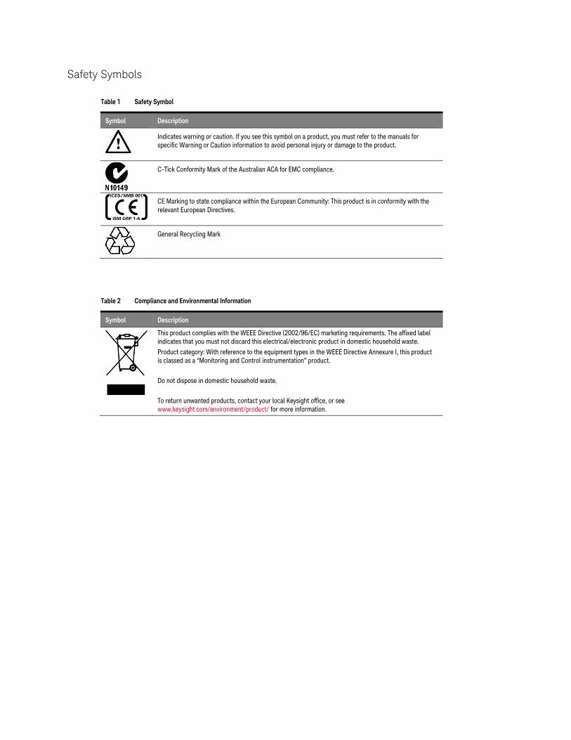
Safety Symbols
Table 1 Safety Symbol
Symbol Description
Indicates warning or caution. If you see this symbol on a product, you must refer to the manuals for
specific Warning or Caution information to avoid personal injury or damage to the product.
C-Tick Conformity Mark of the Australian ACA for EMC compliance.
CE Marking to state compliance within the European Community: This product is in conformity with the
relevant European Directives.
General Recycling Mark
Table 2 Compliance and Environmental Information
Symbol Description
This product complies with the WEEE Directive (2002/96/EC) marketing requirements. The affixed label
indicates that you must not discard this electrical/electronic product in domestic household waste.
Product category: With reference to the equipment types in the WEEE Directive Annexure I, this product
is classed as a “Monitoring and Control instrumentation” product.
Do not dispose in domestic household waste.
To return unwanted products, contact your local Keysight office, or see
www.keysight.com/environment/product/ for more information.


Contents
Keysight M8195A User’s Guide 7
Contents
1 Introduction
1.1 Document History 13
1.2 Options 14
1.3 The Front Panel of the M8195A Rev 001 16
2 M8195A User Interface
2.1 Introduction 17
2.2 Launching the M8195A Soft Front Panel 18
2.3 M8195A User Interface Overview 20
2.3.1 Title Bar 20 2.3.2 Menu Bar 20 2.3.3 Status Bar 22 2.3.4 Clock/Output/Standard Waveform/ Multi-Tone
Waveform/Complex Modulated Waveform/Import
Waveform/Status/Control Tabs 22 2.3.5 Numeric Control Usage 22
2.4 Driver Call Log 24
2.5 Errors Window 25
2.6 Clock Tab 26
2.7 Output Tab 27
2.8 Standard Waveform Tab 29
2.9 Multi-Tone Waveform Tab 36
2.10 Complex Modulated Waveform Tab 41
2.11 Import Waveform Tab 50
2.12 Correction File Format 55
3 General Programming
3.1 Introduction 57
3.2 IVI-COM Programming 58
3.3 SCPI Programming 59
3.3.1 AgM8195SFP.exe 60
3.4 Programming Recommendations 62
3.5 System Related Commands (SYSTem Subsystem) 63
3.5.1 :SYSTem:ERRor[:NEXT]? 63 3.5.2 :SYSTem:HELP:HEADers? 63 3.5.3 :SYSTem:LICense:EXTended:LIST? 65 3.5.4 :SYSTem:SET[?] 65 3.5.5 :SYSTem:VERSion? 65 3.5.6 :SYSTem:COMMunicate:*? 66
Contents
8 Keysight M8195A User’s Guide
3.6 Common Command List 69
3.6.1 *IDN? 69 3.6.2 *CLS 69 3.6.3 *ESE 69 3.6.4 ESR? 70 3.6.5 *OPC 70 3.6.6 *OPC? 70 3.6.7 *OPT? 70 3.6.8 *RST 70 3.6.9 *SRE[?] 71 3.6.10 *STB? 71 3.6.11 *TST? 71 3.6.12 *LRN? 71 3.6.13 *WAI? 71
3.7 Status Model 72
3.7.1 :STATus:PRESet 74 3.7.2 Status Byte Register 74 3.7.3 Questionable Data Register Command Subsystem 75 3.7.4 Operation Status Subsystem 77 3.7.5 Voltage Status Subsystem 79 3.7.6 Connection Status Subsystem 80 3.7.7 Run Status Subsystem 81
3.8 :ARM/TRIGger Subsystem 82
3.8.1 :ABORt[1|2|3|4 82 3.8.2 :INITiate:IMMediate[1|2|3|4] 82
3.9 :INSTrument Subsystem 82
3.9.1 :INSTrument:SLOT[:NUMBer]? 82 3.9.2 :INSTrument:IDENtify [<seconds>] 83 3.9.3 :INSTrument:IDENtify:STOP 84 3.9.4 :INSTrument:DACMode[?] [DUALchannel|FOURchannel] 84
3.10 :MMEMory Subsystem 84
3.10.1 :MMEMory:CATalog? [<directory_name>] 85 3.10.2 :MMEMory:CDIRectory [<directory_name>] 85 3.10.3 :MMEMory:COPY <string>,<string>[,<string>,<string>] 86 3.10.4 :MMEMory:DELete <file_name>[,<directory_name>] 87 3.10.5 :MMEMory:DATA <file_name>, <data> 87 3.10.6 :MMEMory:DATA? <file_name> 88 3.10.7 :MMEMory:MDIRectory <directory_name> 88 3.10.8 :MMEMory:MOVE <string>,<string>[,<string>,<string>] 88 3.10.9 :MMEMory:RDIRectory <directory_name> 90 3.10.10 :MMEMory:LOAD:CSTate <file_name> 90 3.10.11 :MMEMory:STORe:CSTate <file_name> 90
3.11 :OUTPut Subsystem 91
3.11.1 :OUTPut[1|2|3|4][:STATe][?] OFF|ON|0|1 91
3.12 Sampling Frequency Commands 92
Contents
Keysight M8195A User’s Guide 9
3.12.1 [:SOURce]:FREQuency:RASTer[?]
<frequency>|MINimum|MAXimum 92
3.13 :VOLTage Subsystem 93
3.13.1 [:SOURce]:VOLTage[1|2|3|4][:LEVel][:IMMediate][:AMPLitude][?]
<level> 93 3.13.2 [:SOURce]:VOLTage[1|2|3|4][:LEVel][:IMMediate]:OFFSet[?]
<level> 94 3.13.3 [:SOURce]:VOLTage[1|2|3|4][:LEVel][:IMMediate]:HIGH[?]
<level> 94 3.13.4 [:SOURce]:VOLTage[1|2|3|4][:LEVel][:IMMediate]:LOW[?]
<level> 94
3.14 Frequency and Phase Response Data Access 95
3.14.1 [:SOURce]: CHARacterist[1|2|3|4][:VALue]? 95
3.15 :TRACe Subsystem 95
3.15.1 Waveform Memory Capacity 96 3.15.2 Waveform Length Granularity and Size 96 3.15.3 Waveform Data Format 96 3.15.4 Arbitrary Waveform Generation 97 3.15.5 :TRAC[1|2|3|4]:DEF 98 3.15.6 :TRAC[1|2|3|4]:DEF:NEW? 99 3.15.7 :TRAC[1|2|3|4]:DEF:WONL 100 3.15.8 :TRAC[1|2|3|4]:DEF:WONL:NEW? 101 3.15.9 :TRAC[1|2|3|4]:DATA[?] 102 3.15.10 :TRAC[1|2|3|4]:IMP 103 3.15.11 :TRAC[1|2|3|4]:DEL 110 3.15.12 :TRAC[1|2|3|4]:DEL:ALL 110 3.15.13 :TRAC[1|2|3|4]:CAT? 110 3.15.14 :TRAC[1|2|3|4]:FREE? 110 3.15.15 :TRAC[1|2|3|4]:NAME[?] 111 3.15.16 :TRAC[1|2|3|4]:COMM[?] 112
3.16 :TEST Subsystem 113
3.16.1 :TEST:PON? 113 3.16.2 :TEST:TST? 113
4 Examples
4.1 Introduction 115
4.2 Remote Programming Examples 115
4.3 Example Files for Import 115
4.4 Example Correction Files 115
4.5 Example Custom Modulation Files 116
5 Appendix
5.1 Resampling Algorithms for Waveform Import 117
5.1.1 Resampling Requirements 117 5.1.2 Resampling Methodology 118

Contents
10 Keysight M8195A User’s Guide

Keysight M8195A – Arbitrary Waveform Generator
User’s Guide
Keysight M8195A User’s Guide
1 Introduction
1.1 Document History / 13
1.2 Options / 14
1.3 The Front Panel of the M8195A Rev 001 / 16
Introduction The Keysight M8195A is a 65 GSa/s Arbitrary Waveform Generator with highest
bandwidth and channel density. It offers up to 16 GSa waveform memory. The
M8195A is ideally suited to address following key applications:
Coherent optical – a single M8195A module can generate 2 independent
I/Q baseband signals (dual polarization = 4 channels) at up to 32 Gbaud
and beyond.
Multi-level / Multi-channel digital signals – generate NRZ, PAM4, PAM8,
DMT, etc. signals at up to 32 Gbaud. Embed/De-embed channels, add
Jitter, ISI, noise and other distortions.
Physics, chemistry, and electronics research – generate any
mathematically defined arbitrary waveforms, ultra-short yet precise pulses
and extremely wideband chirps.
Wideband RF/µW – generate extremely wideband RF signals with an instantaneous
bandwidth of DC to 20 GHz for aerospace/defense/communication applications.
Introduction
12 M8195A User’s Guide
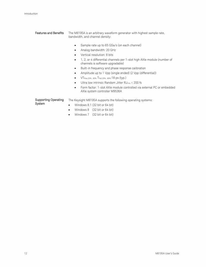
Features and Benefits The M8195A is an arbitrary waveform generator with highest sample rate,
bandwidth, and channel density:
Sample rate up to 65 GSa/s (on each channel)
Analog bandwidth: 20 GHz
Vertical resolution: 8 bits
1, 2, or 4 differential channels per 1-slot high AXIe module (number of
channels is software upgradable)
Built-in frequency and phase response calibration
Amplitude up to 1 Vpp (single ended) (2 Vpp (differential))
VTRise,20%...80% TFall,20%...80%:18 ps (typ.)
Ultra low intrinsic Random Jitter RJrms < 200 fs
Form factor: 1-slot AXIe module controlled via external PC or embedded
AXIe system controller M9536A
Supporting Operating
System The Keysight M8195A supports the following operating systems:
Windows 8.1 (32 bit or 64 bit)
Windows 8 (32 bit or 64 bit)
Windows 7 (32 bit or 64 bit)

Introduction
M8195A User’s Guide 13
Additional Documents Additional documentation can be found at:
http://www.keysight.com/find/M9514A for 13-slot chassis related
documentation.
http://www.keysight.com/find/M9505A for 5-slot chassis related
documentation.
http://www.keysight.com/find/M9502A for 2-slot chassis related
documentation.
http://www.keysight.com/find/M9045A for PCIe laptop adapter card related
documentation.
http://www.keysight.com/find/M9047A for PCIe desktop adapter card related
documentation.
http://www.keysight.com/find/M9536A for embedded AXIe controller related
documentation.
http://www.keysight.com/find/M8195A for AXIe based AWG module related
documentation.
1.1 Document History
First Edition
(September, 2014)
The first edition of the User’s Guide describes the functionality of the M8195A Version
1.0 .
Second Edition
(October, 2014)
The second edition of the User’s Guide describes the functionality of the M8195A
Version 1.1.

Introduction
14 M8195A User’s Guide
1.2 Options
For the M8195A Rev001, following product options are available.
Table 3: Options provided by M8195A
Product Number Description Comment
M8195A-R12 2 channel, 65 GSa/s AWG, 256
kSa per channel Must order either –R12 or -R14
M8195A-R14 4 channel, 65 GSa/s AWG, 256
kSa per channel
Must order either –R12 or -R14
M8195A-U12
Upgrade from Rev 1 to Rev 2 for
M8195A-R12 Hardware exchange
M8195A-U14
Upgrade from Rev 1 to Rev 2 for
M8195A-R14 Hardware exchange

Introduction
M8195A User’s Guide 15
Option -R12 or -R14 With this option the number of channels is selected. The M8195A is available as a two
channel (-R12) or 4 channel (-R14) instrument. There is no upgrade possible from
option –R12 to option -R14.
Option -U12 or -U14 These options can be ordered to get an upgrade from M8195A Rev001 to the M8195A
Rev 002. This upgrade is offered as a hardware exchange.

Introduction
16 M8195A User’s Guide
1.3 The Front Panel of the M8195A Rev 001
The Front Panel of the M8195A Rev 001 is shown in the figure below.
Figure 1: Front panel of M8195A
Outputs The M8195A offers two or four differential analog outputs of the Digital to Analog
Converters (DAC).
Note: The 2-channel version (-R12) and the 4-channel version (-R14) are both
equipped with four differential outputs. The 2-channel version uses channel 1 and
channel 4. Channels 2 and 3 are always disabled.
Note: The Data Outputs can be used differentially or single-ended. In case the output
is used single-ended, the unused output must be terminated with 50 Ohm to GND to
achieve optimum signal quality.
Status LED Following LEDs are available at the front panel to indicate the status of the AWG
module:
The green ‘Access’ LED:
o It indicates that the controlling PC exchanges data with the AWG
module.
The red ‘Fail’ LED has following functionality:
o It is ‘ON’ for about 30 seconds after powering the AXIe chassis.
o After about 30 seconds the LED is switched ‘OFF’. If an external PC is
used to control the AXIe chassis, this PC can be powered after this LED
has switched OFF.
o During normal operation of the module this LED is ‘OFF’. In case of an
error condition such as e.g. a self-test error, the LED is switch ‘ON’.
Four ‘Channel’ LEDs:
o It is ‘OFF’ when the channel is disabled and no overload condition at
this channel has been detected.
o It is ‘GREEN’ if the channel is enabled and no overload condition at this
channel has been detected.
o It is ‘RED’ if the internal protection circuit of that channel has detected
an overload condition. Potential overload conditions are e.g. an
external short to GND or 50 Ohm termination to a wrong externally
applied termination voltage VTerm. In case an overload condition is
detected, remove the overload condition of the test set-up and enable
the channel.

Keysight M8195A – Arbitrary Waveform Generator
User’s Guide
Keysight M8195A User’s Guide
2 M8195A User Interface
2.1 Introduction / 17
2.2 Launching the M8195A Soft Front Panel / 18
2.3 M8195A User Interface Overview / 20
2.4 Driver Call Log / 24
2.5 Errors Window / 25
2.6 Clock Tab / 26
2.7 Output Tab / 27
2.8 Standard Waveform Tab / 29
2.9 Multi-Tone Waveform Tab / 36
2.10 Complex Modulated Waveform Tab / 41
2.11 Import Waveform Tab / 50
2.12 Correction File Format / 55
2.1 Introduction
This chapter describes the M8195A Soft Front Panel.

M8195A User Interface
18 M8195A User’s Guide
2.2 Launching the M8195A Soft Front Panel
There are three ways to launch the M8195A Soft Front Panel:
1. Select Start > All Programs > Keysight M8195 > Keysight M8195 Soft Front
Panel from the Start Menu.
2. From the Keysight Connection Expert select the discovered M8195 module,
press the right mouse key to open the context menu and select “Send
Commands To This Instrument”.
3. From the Keysight Connection Expert select the discovered M8195 module,
select the “Installed Software” tab and press the “Start SFP” button.
The following screen will appear:
Figure 2: M8195A connected to PC

M8195A User Interface
M8195A User’s Guide 19
The instrument selection dialog shows the addresses of the discovered M8195A
modules. Select a module from the list and press “Connect”.
If no M8195A module is connected to your PC, you can check “Simulation Mode” to
simulate an M8195A module.
Figure 3: M8195A connected in simulation mode

M8195A User Interface
20 M8195A User’s Guide
2.3 M8195A User Interface Overview
The M8195A user interface includes the following GUI items:
Title Bar
Menu Bar
Status Bar
Tabs (Clock, Output, Standard Waveform, Multi-Tone Waveform, Complex
Modulated Waveform, and Import Waveform)
The detailed information on these GUI items is described in the sections that follow.
2.3.1 Title Bar
The title bar contains the standard Microsoft Windows elements such as the window
title and the icons for minimizing, maximizing, or closing the window.
2.3.2 Menu Bar
The menu bar consists of various pull down menus that provide access to the different
functions and launch interactive GUI tools.
The menu bar includes the following pull down menu:
File
View
Utilities
Tools
Help
Each menu and its options are described in the following sections.
2.3.2.1 File Menu
The File menu includes the following selections:
File – Connect…
Opens the instrument selection dialog.
File – Save Configuration As…
Saves configuration as a text file.
File – Load Configuration…
Load the previously saved configuration file.
File – Exit
Exits the user interface.
M8195A User Interface
M8195A User’s Guide 21
2.3.2.2 View Menu
The View menu includes the following selections:
View – Refresh
Reads the instrument state and updates all fields.
2.3.2.3 Utilities Menu
The Utility menu includes the following selections:
Utility – Reset
Resets the instrument, reads the state and updates all fields.
Utility – Errors…
Opens the Errors Window to display the errors reported by the instrument.
Utility – Self Test…
Opens a window to start the self-test and display the result after completion.
2.3.2.4 Tools Menu
The Tools menu includes the following selections:
Tools – Monitor Driver Calls
Opens the Driver Call Log window.
2.3.2.5 Help Menu
The Help menu includes the following selections:
Help – Online Support
Opens the instrument’s product support web page.
Help – About
Displays revision information for hardware, software and firmware. Displays the
serial number of the connected module.
M8195A User Interface
22 M8195A User’s Guide
2.3.3 Status Bar
The Status Bar contains three fields from left to right:
Connection state
“Not Connected” – No instrument is connected.
“Connected: <Instrument resource string>” – An instrument is connected. The
resource string, for example PXI36::0::0::INSTR is displayed.
“Simulation Mode” – No real instrument is connected. The user interface is in
simulation mode.
Click this field to open the Instrument Selection Dialog.
Instrument status
Displays the instrument status, for example “Reset complete” after issuing a reset
command. In case of error it displays additional error information.
Error status
“Error” – The connected instrument reported an error.
“No Error” – No errors occurred.
Click this field to open the Report Error Window.
2.3.4 Clock/Output/Standard Waveform/ Multi-Tone Waveform/Complex Modulated
Waveform/Import Waveform Tabs
These tabs are used to configure the most important parameters of the M8195A
module. They are described in detail in the sections that follow.
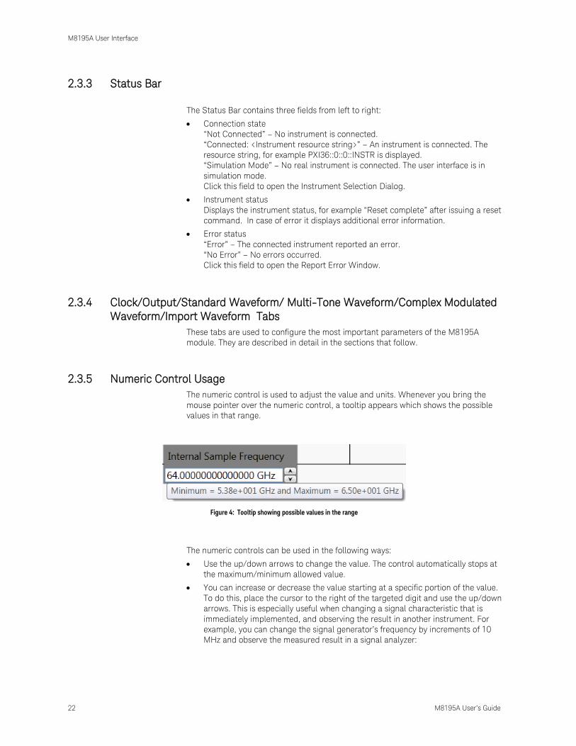
2.3.5 Numeric Control Usage
The numeric control is used to adjust the value and units. Whenever you bring the
mouse pointer over the numeric control, a tooltip appears which shows the possible
values in that range.
Figure 4: Tooltip showing possible values in the range
The numeric controls can be used in the following ways:
Use the up/down arrows to change the value. The control automatically stops at
the maximum/minimum allowed value.
You can increase or decrease the value starting at a specific portion of the value.
To do this, place the cursor to the right of the targeted digit and use the up/down
arrows. This is especially useful when changing a signal characteristic that is
immediately implemented, and observing the result in another instrument. For
example, you can change the signal generator’s frequency by increments of 10
MHz and observe the measured result in a signal analyzer:

M8195A User Interface
M8195A User’s Guide 23
Figure 5: : Typing directly into the field
Type directly into the field and press the Enter key. If you enter a value outside the
allowed range, the control automatically limits the entered value to the maximum
or minimum allowed value.
When you type the value, you can type the first letter of the allowed unit of
measure to set the units. For example, in the Frequency control you can use "H",
"K", "M", or "G" to specify hertz, kilohertz, megahertz, or gigahertz, respectively.
(The control is not case sensitive.)
The controls allow scientific notation if it is appropriate to the allowed range. Type the
first decimal number, enter an "E", and omit any trailing zeroes. For example, in the
Frequency control you can type 2.5e+9 and press Enter to set the frequency to 2.5 GHz.
(The plus sign is automatically inserted if it is omitted.)
M8195A User Interface
24 M8195A User’s Guide
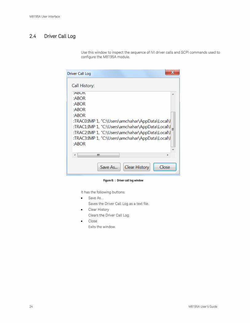
2.4 Driver Call Log
Use this window to inspect the sequence of IVI driver calls and SCPI commands used to
configure the M8195A module.
Figure 6: : Driver call log window
It has the following buttons:
Save As…
Saves the Driver Call Log as a text file.
Clear History
Clears the Driver Call Log.
Close
Exits the window.
M8195A User Interface
M8195A User’s Guide 25
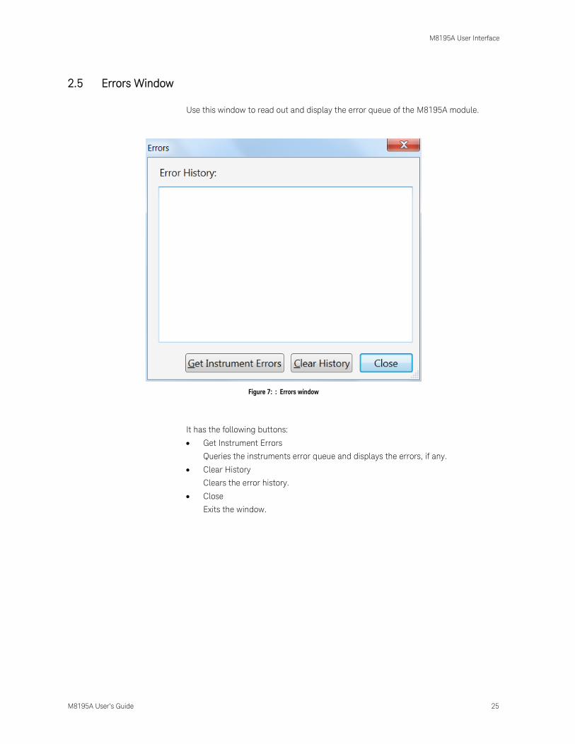
2.5 Errors Window
Use this window to read out and display the error queue of the M8195A module.
Figure 7: : Errors window
It has the following buttons:
Get Instrument Errors
Queries the instruments error queue and displays the errors, if any.
Clear History
Clears the error history.
Close
Exits the window.

M8195A User Interface
26 M8195A User’s Guide
2.6 Clock Tab
Use this tab to configure the sample clock of the M8195A module. The sample clock for
all four Digital to Analog Converters (DAC) of the four channels is identical. The Internal
Sample Frequency is derived from a fix Internal Reference clock.
Figure 8: Clock tab

M8195A User Interface
M8195A User’s Guide 27
2.7 Output Tab
Use this tab to configure the Data Outputs (Channel 1, Channel 2, Channel 3 and
Channel 4) of the M8195A AWG module.
The M8195A has two different Modes of operation:
Mode: 2 Channel. This mode is always available. If this mode is selected,
Channel 1 and Channel 4 are used to generate data. Channel 2 and Channel 3
are powered down and can not be enabled.
Mode: 4 Channel: This mode is only selectable, if option –R14 is installed. If
this mode is selected, all four channels can be used to generate data.
The Run/Stop button is used to switch between Run and Program mode.
Figure 9: Output tab
M8195A User Interface
28 M8195A User’s Guide
Each channel has the following input fields:
Amplitude
Specifies the amplitude of the output signal.
Offset
Specifies the offset of the output signal.
Output status indicator. This indicator reflects the color of the ‘Channel’ LED
on the front panel:
o It is ‘OFF’ when the channel is disabled and no overload condition at this
channel has been detected.
o It is ‘GREEN’ if the channel is enabled and no overload condition at this
channel has been detected.
o It is ‘RED’ if the internal protection circuit of that channel has detected an
overload condition. Potential overload conditions are e.g. an external
short to GND or 50 Ohm termination to a wrong externally applied
termination voltage VTerm. In case an overload condition is detected,
remove the overload condition of the test set-up and enable the channel.
Output enable switch
If set to enabled position, the generated signal is present at the output.

M8195A User Interface
M8195A User’s Guide 29
2.8 Standard Waveform Tab
Use this tab to create a variety of standard waveform types. It provides the controls
which allow the complete definition of signal generation parameters for the following
waveform shapes:
Sinusoidal
Square with linear transitions
Square with cosine-shaped transitions
Triangle
Sinc (Sin x/x)
Bandwidth-limited Gaussian noise
The standard waveform tab allows you to generate signals for both direct and I/Q data
generation modes. It also provides a graphic waveform preview functionality, which can
be used to validate created signals before sending them to the instrument. The created
signals can also be stored in a file for later use. The application takes care of handling
the requirements and limits of the target hardware in aspects such as maximum and
minimum record lengths and sampling rate and record length granularity. As a result,
the signals designed in this tab will be always feasible to be generated by the
instrument and free of distortions such as wrap-around or timing artifacts, even if the
signal is generated in looped mode.

M8195A User Interface
30 M8195A User’s Guide
Figure 10: Standard waveform tab

M8195A User Interface
M8195A User’s Guide 31
This tab has the following controls:
Waveform Destination Section
Channel
Independent checkboxes allow the definition of standard waveforms for Channel 1,
Channel 2, Channel 3 or Channel 4. One of the boxes is always checked. When
pressing the ‘Send To Instrument’ button, the waveform is sent to all channels that
are checked.
Generate I/Q Data
If checked, baseband (I/Q) signals will be generated. The effect of this control
depends on the selected signal type. For Sinusoidal waves, the resulting complex
signal will be a single spectral line located at positive or negative frequencies. This
implies that users can type negative numbers into the “Waveform Freq.” field. . For
noise, the resulting complex signal will be a limited-bandwidth Gaussian noise
with uncorrelated positive and negative frequency components. All the other
waveform types result in the same signal being generated by both I and Q assigned
channels.
I/Q Toggle buttons
I/Q selection toggle buttons for each channel will be shown when the Generate I/Q
Data checkbox is checked. In-Phase (I) and Quadrature (Q) components can be
independently assigned to each channel.
Segment Number
Target segment for each channel can be defined independently. The segment
number is for future use. It is always set to Segment 1.

M8195A User Interface
32 M8195A User’s Guide
Basic Waveform Parameters Section
Waveform Type:
The following waveform types are available:
Sine: Sinusoidal waveform. Frequency and Initial Phase parameters can
be defined for this waveform type using the corresponding controls. If the
Generate I/Q checkbox is checked, two sine waves with a 90º phase
difference will be assigned to the I and Q components.
Square_Linear: Square signal with linear transitions. Frequency, Rise
Time, Fall Time, Duty Cycle, and Initial Phase parameters can be defined
for this waveform type using the corresponding controls.
Square_Cos: Square signal with cosine shaped transitions. Frequency,
Rise Time, Fall Time, Duty Cycle, and Initial Phase parameters can be
defined for this waveform type using the corresponding controls.
Triangle: Triangular waveform with linear transitions. Frequency,
Symmetry, and Initial Phase parameters can be defined for this waveform
type using the corresponding controls.
Sinc: Sin x/x waveform. Frequency, Symmetry, Sinc Length, and Initial
Phase parameters can be defined for this waveform type using the
corresponding controls.
Noise: Gaussian noise with limited bandwidth. Frequency, Crest Factor,
and Noise Bandwidth parameters can be defined for this waveform type
using the corresponding controls. If the Generate I/Q checkbox is
checked, two uncorrelated noise waveforms will be assigned to the I and
Q components.
Waveform Frequency
Repetition rate for one cycle of the standard waveform. It is always a positive
number except when Signal Type is set to Sine and the Generate I/Q Data
checkbox is checked. In this case, frequency may be negative so the resulting SSB
(Single-Side Band) will be located over or below the carrier frequency.
Initial Phase
The phase within a normalized cycle of the standard waveform for the first sample
in the segment.
Duty Cycle
The relative width as a percentage of the mark and the space sections of square
waves.

M8195A User Interface
M8195A User’s Guide 33
Rise Time
The transition time (10%-90%) for the rising edge in square waveforms.
Fall Time
The transition time (10%-90%) for the falling edge in square waveforms.
Symmetry
For both triangular and sinc waveforms, it marks the location as a percentage of
the positive highest peak within a period of the basic signal.
Sinc Length
The number of zero crossings in a single period for the sinc waveform type.
Crest Factor
The peak-to-average power ratio in dBs for Noise samples before low-pass
filtering. Actual crest factor in the final signal after filtering will be higher.
Noise Bandwidth
Baseband noise bandwidth for Noise waveforms. For IQ modes, noise bandwidth
around the carrier frequency will be twice this parameter.
Additional Waveform Parameters Section
Preamble Length
The duration of a DC section before the defined Standard waveform starts.
Preamble Level
The level for the DC section before the defined Standard waveform starts.
Acceptable range for this parameter is -1/+1, being the full dynamic range of the
instrument’s DAC.
Postamble Length
The duration of a DC section after the defined Standard waveform stops.
Postamble Level
The level for the DC section after the defined Standard waveform stops. Acceptable
range for this parameter is -1/+1, being the full dynamic range of the instrument’s
DAC.
Keep Periods
This checkbox is only available when “Keep Sample Rate” is selected. When this
option is selected, the waveform calculation algorithm preserves the user-defined
number of periods.
Set WL to Max
This checkbox is only available when “Keep Sample Rate” is selected. When this
option is selected, the waveform calculation algorithm always takes the maximum
waveform length as defined in the “Max. Wfm. Length”. As the waveform length
must always be identical for all four channels, it is recommended to check the “Set
WL to Max” box in case different waveforms shall be downloaded to different
channels.
Periods
The number of repetition of single periods of the standard waveform within the
target segment. This parameter is set automatically when Frequency is changed
and preamble and postamble lengths are set to zero in order to

M8195A User Interface
34 M8195A User’s Guide
obtain the best timing accuracy and meet the record length granularity
requirements.
Waveform Length
The length in samples of the resulting segment. It may be set within acceptable
limits and it may be calculated automatically to properly implement other signal
and instrument parameters such as sampling rate.
Max. Wfm. Length
Maximum waveform length must be used to force the resulting waveform to be
shorter than or equal to a user-set limit.
Keep Sample Rate
This check box preserves the sampling rate to a user-defined value no matter how
any other signal parameters may be defined. Keeping the sampling rate to a fixed
value may be necessary when multiple waveforms are created to be used in a
sequence or scenario. The “Set WL to Max” check box gets activated when this
check box is checked.
Set WL to Max
This check box forces the usage of the number of samples defined in the “Max.
Wfm. Length” numeric entry field. Some waveform parameters may be adjusted to
make sure that continuous play-back of the waveform is seamless.
Scaling Section
DAC Max
Standard waveforms may occupy a limited range of the DAC’s full scale. This
parameter sets the maximum level. If set to a lower level than DAC Min, this will be
automatically set to the same level. Acceptable range for this parameter is -1/+1,
being the full dynamic range of the instrument’s DAC.
DAC Min
Standard waveforms may occupy a limited range of the DAC’s full scale. This
parameter sets the minimum level. If set to a higher level than DAC Max, this will
be automatically set to the same level. Acceptable range for this parameter is -
1/+1, being the full dynamic range of the instrument’s DAC.

M8195A User Interface
M8195A User’s Guide 35
Preview Section
Waveform Preview Toolbar
The waveform preview toolbar includes the icons to preview the waveform. The
following icons are available:
Uses the mouse to control the marker. The respective position
of marker at X and Y axis are displayed on the top of
waveform.
Takes the marker to the peak position
Sets the marker on the I data part of the waveform
Sets the marker on the Q data part of the waveform
Turns off the marker
Provides zoom functionality. Use the mouse pointer to select
the area on waveform that you want to zoom. Once done, you
can click Auto scale icon to zoom out the waveform.
Uses the mouse pointer to move the waveform around. You
can also use the pan tool when the waveform is zoomed in.
Auto scale the waveform
Save To File…
Signals can be stored in files in whether BIN (for non IQ modes) or IQBIN (for IQ
modes) formats. These files may be reused within the Import Waveform tab.
Send To Instrument
Signal will be transferred to the selected segments of the selected channels. The
previous running status for the target instrument will be preserved but sampling
rate may be modified depending on the waveform requirements.
Set Default
All the standard waveform parameters are set automatically to their corresponding
default values.
M8195A User Interface
36 M8195A User’s Guide
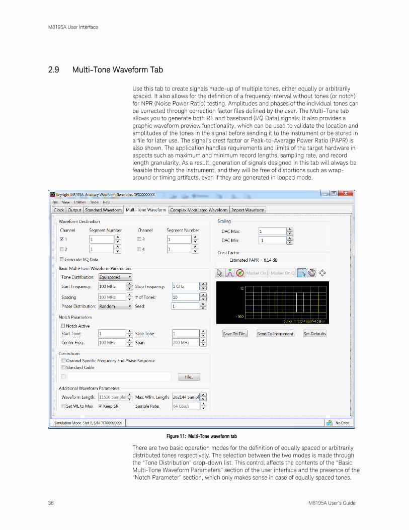
2.9 Multi-Tone Waveform Tab
Use this tab to create signals made-up of multiple tones, either equally or arbitrarily
spaced. It also allows for the definition of a frequency interval without tones (or notch)
for NPR (Noise Power Ratio) testing. Amplitudes and phases of the individual tones can
be corrected through correction factor files defined by the user. The Multi-Tone tab
allows you to generate both RF and baseband (I/Q Data) signals. It also provides a
graphic waveform preview functionality, which can be used to validate the location and
amplitudes of the tones in the signal before sending it to the instrument or be stored in
a file for later use. The signal’s crest factor or Peak-to-Average Power Ratio (PAPR) is
also shown. The application handles requirements and limits of the target hardware in
aspects such as maximum and minimum record lengths, sampling rate, and record
length granularity. As a result, generation of signals designed in this tab will always be
feasible through the instrument, and they will be free of distortions such as wrap-
around or timing artifacts, even if they are generated in looped mode.
Figure 11: Multi-Tone waveform tab
There are two basic operation modes for the definition of equally spaced or arbitrarily
distributed tones respectively. The selection between the two modes is made through
the “Tone Distribution” drop-down list. This control affects the contents of the “Basic
Multi-Tone Waveform Parameters” section of the user interface and the presence of the
“Notch Parameter” section, which only makes sense in case of equally spaced tones.

M8195A User Interface
M8195A User’s Guide 37
However, controls in the other control groups are valid and operative for both operating
modes. Equally spaced tones are defined on the basis of their common parameters such
as start and stop frequencies, and tone spacing or number of tones or both. Arbitrarily
distributed tones are defined through a table. In order to simplify the creation of
complex scenarios, the tones defined in the equally spaced mode are loaded into the
tone table every time the user switches to the arbitrary mode and the tone table is
empty. In this way, any number of tones may be easily defined in the equally spaced
mode, and then the resulting table may be edited for frequency, amplitude, or phase for
each individual tone. Tones may also be deleted or added.
This tab has the following controls:
Waveform Destination Section
Generate I/Q Data
If checked, baseband (I/Q) signals will be generated. The resulting complex signal
will be a series of tones located at positive and/or negative frequencies. As a
consequence, negative values can be typed into any waveform frequency edition
field in this panel when this checkbox is checked.
I/Q Toggle buttons
I/Q selection toggle buttons for each channel will be shown when the Generate I/Q
Data checkbox is checked. In-Phase (I) and Quadrature (Q) components can be
independently assigned to each channel.
Channel Independent checkboxes allow the definition of Multi-Tone waveforms for
Channel 1, Channel 2, Channel 3 or Channel 4. One of the boxes is always checked.
When pressing the ‘Send To Instrument’ button, the waveform is sent to all
channels that are checked.
Segment Number
Target segment for each channel can be defined independently. The segment
number is for future use. It is always set to Segment 1.
Corrections Section
File…
Open a correction file selection dialog box. Default file extensions match the File
Format selection. The name of the successfully loaded correction factors file is
shown in the field located at the left of this button. The accepted format for
correction files may be found in the Correction File Format section.
Channel Specific Frequency and Phase Response
This checkbox activates the application of corrections based on frequency-domain
calibration data stored in the target instrument in an internal non-volatile memory.
It improves flatness and linear phase distortion.
Standard Cable
This checkbox activates the application of correction factors based on a typical
high-quality, high-bandwidth 0.85m microwave cable (Huber+Suhner type
M8041-61616).
Additional Waveform Parameters Section
Waveform Length
It is indicator only. The length is in samples of the resulting segment.
Max. Wfm. Length
Maximum waveform length must be used to force the resulting waveform to be

M8195A User Interface
38 M8195A User’s Guide
shorter than or equal to the limit set by the user.
Keep Sample Rate
This check box preserves the sampling rate to a user-defined value irrespective of
the manner in which other signal parameters may be defined. Keeping the
sampling rate to a fixed value may be necessary when multiple waveforms are
created for usage in a sequence or scenario. The “Set WL to Max” checkbox shows
up when this check box is checked.
Set WL to Max
This checkbox is only available when “Keep Sample Rate” is selected. When this
option is selected, the waveform calculation algorithm always takes the maximum
waveform length as defined in the “Max. Wfm. Length”. As the waveform length
must always be identical for all four channels, it is recommended to check the “Set
WL to Max” box in case different waveforms shall be downloaded to different
channels.
Sample Rate
Final DAC conversion rate for the resulting signal. It may be set by the user or
automatically calculated depending on other signal parameters.
Scaling Section
DAC Max
Multi-Tone waveforms may occupy a limited range of the DAC’s full scale. This
parameter sets the maximum level. If set to a lower level than DAC Min, this will be
automatically set to the same level. Acceptable range for this parameter is -1/+1,
being the full dynamic range of the instrument’s DAC.
DAC Min
Multi-Tone waveforms may occupy a limited range of the DAC’s full scale. This
parameter sets the minimum level. If set to a higher level than DAC Max, this will
be automatically set to the same level. Acceptable range for this parameter is -
1/+1, being the full dynamic range of the instrument’s DAC.
Crest Factor Section
It is an indicator only.
It shows the estimated PAPR for the current waveform in dB. Although the
definition of the PAPR parameter is always the ratio between the peak and the
average power for a signal, results change depending on the working mode. For
the I/Q Data Generation mode, the result reflects the PAPR of the envelope of the
resulting signal while for direct generation it reflects the overall signal. The
difference between the former and the latter values is close to +3dBs in most
cases.
Preview Section
Multi-Tone Preview Toolbar
The waveform preview toolbar includes the icons that provide different
functionality to preview the waveform. For details, see Preview Section
Waveform Preview ToolbarPreview Toolbar.
Compilation and Panel Control Section
Save To File…
Signals can be stored in files either in BIN (for non IQ modes) or IQBIN (for IQ
modes) formats. These files may be reused within the Import Waveform tab.
M8195A User Interface
M8195A User’s Guide 39
Send To Instrument
Signal will be transferred to the selected segments of the selected channels. The
previous running status for the target instrument will be preserved but sampling
rate may be modified depending on the waveform requirements.
Set Default
All the Multi-Tone waveform parameters are set automatically to their
corresponding default values. Entries in the Arbitrary Tone table are not modified
by this button.
Two control sections show-up for equally spaced tone definition (“Equispaced” selected
in the Tone Distribution drop-down list): “Basic Multi-Tone Waveform Parameters” and
“Notch Parameters”.
Basic Multi-Tone Waveform Parameters Section
Start Frequency
It is the frequency of the first tone. If it is set to a value higher than the one in the
Stop Frequency field, this is changed back to the previous Start Frequency.
Stop Frequency
It is the frequency of the last tone. If it is set to a value lower than the one in the
Stop Frequency field, this is changed back to the previous Stop Frequency.
Spacing
It is an indicator only.
Spacing = (Stop Frequency – Start Frequency)/(# of Tones – 1).
# of Tones
It is the total number of tones in the Multi-Tone signal including the ones in the
notch, if any.
Phase Distribution
Phase for each tone can be set in the three different modes: constant, random, and
parabolic. While constant phase Multi-Tone signals show a high crest factor, a
random phase distribution results in a much lower value for this parameter while a
parabolic distribution results in a close to optimal (or minimum) crest factor.
Seed
This parameter is associated to the random phase distribution and allows
generating the same or different random sequences for the phases of each tone. It
is also useful to look for a distribution resulting in a desired crest factor value.
Notch Parameters Section
Notch Active
This check box activates or deactivates the generation of a notch in the equally
spaced Multi-Tone signal.
Start Tone
It is the index of the first tone to be removed in a notch. Acceptable indexes start
with 1.
Stop Tone
It is the index of the last tone to be removed in a notch. Acceptable indexes start
with 1.
Center Frequency
It is an indicator only. The central frequency for the notch is computed and shown
in this field.
M8195A User Interface
40 M8195A User’s Guide
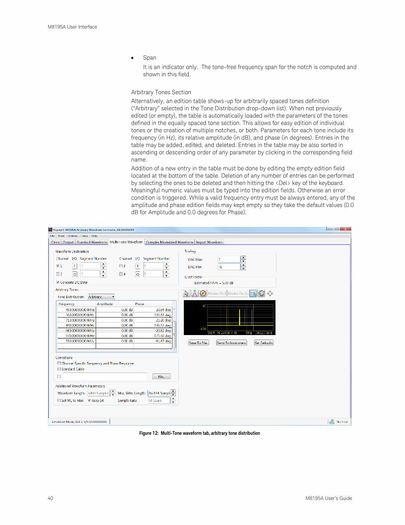
Span
It is an indicator only. The tone-free frequency span for the notch is computed and
shown in this field.
Arbitrary Tones Section
Alternatively, an edition table shows-up for arbitrarily spaced tones definition
(“Arbitrary” selected in the Tone Distribution drop-down list). When not previously
edited (or empty), the table is automatically loaded with the parameters of the tones
defined in the equally spaced tone section. This allows for easy edition of individual
tones or the creation of multiple notches, or both. Parameters for each tone include its
frequency (in Hz), its relative amplitude (in dB), and phase (in degrees). Entries in the
table may be added, edited, and deleted. Entries in the table may be also sorted in
ascending or descending order of any parameter by clicking in the corresponding field
name.
Addition of a new entry in the table must be done by editing the empty edition field
located at the bottom of the table. Deletion of any number of entries can be performed
by selecting the ones to be deleted and then hitting the <Del> key of the keyboard.
Meaningful numeric values must be typed into the edition fields. Otherwise an error
condition is triggered. While a valid frequency entry must be always entered, any of the
amplitude and phase edition fields may kept empty so they take the default values (0.0
dB for Amplitude and 0.0 degrees for Phase).
Figure 12: Multi-Tone waveform tab, arbitrary tone distribution
M8195A User Interface
M8195A User’s Guide 41
2.10 Complex Modulated Waveform Tab
Use this tab to create baseband and IF/RF digitally modulated signals. User-defined
corrections may be applied to signals to compensate for (or emulate) instrument,
interconnections and channel linear distortions. The complex modulation tab allows you
to generate both RF and Baseband (I/Q) signals. It directly supports a large variety of
single-carrier modulation schemes. This is a list of the currently supported standards,
modulation orders and modulation parameters:
ASK (Amplitude Shift Keying): Modulation Index (0%-100%).
PSK (Phase Shift Keying): BPSK, QPSK, π/4-DQPSK, Offset-QPSK (OQPSK), 8PSK,
and 3 π /8 8PSK (EDGE).
QAM (Quadrature Amplitude Modulation): 8QAM, 16QAM, 32QAM, 64QAM,
128QAM, 256QAM, 512QAM, AND 1024QAM.
MSK (Minimum Shift Keying)
APSK (Amplitude-Phase Shift Keying): 16APSK and 32 APSK. R2/R1 and R3/R1
can be set by the user to any desired value.
STAR: STAR16 and STAR32. The R2/R1 parameter may be set for the STAR16
modulation scheme.
VSB (Vestigial Side Band): 8VSB and 16VSB.
FSK (Frequency Shift Keying): 2FSK, 4FSK, 8FSK, and 16FSK. Peak deviation
frequency may be set by the user to any desired value.
Custom: Users may define arbitrary constellations through simple ASCII files that
may be read by the SFP application. Modulations with offset (Q delayed by half a
symbol time) and rotating constellations may be also defined. (Refer to the section
Custom Modulation File Format)
Baseband filter type, characteristics, and different data options may be selected by the
user. The panel provides a constellation preview functionality, which can be used to
validate the selected modulation scheme and the corresponding modulation
parameters. The application takes care of handling the requirements and limits of the
target hardware with respect to maximum and minimum record lengths, sampling rate,
and record length granularity. As a result, generation of the signals designed in this tab
will always be feasible by the instrument and free of distortions such as wrap-around or
timing artifacts at any signal domain (time, frequency, and modulation), even if the
signal is generated in looped mode.

M8195A User Interface
42 M8195A User’s Guide
Figure 13: Complex modulated waveform tab
Only relevant parameters and edition fields are shown in the GUI at any time depending
on the selected generation mode (RF or I/Q) and modulation scheme.
Waveform Destination Section
Generate I/Q Data
If checked baseband (I/Q) signals will be generated.
I/Q Toggle buttons
I/Q selection toggle buttons for each channel will be shown when the Generate I/Q
Data checkbox is checked. In-Phase (I) and Quadrature (Q) components can be
independently assigned to each channel.
Apply Offset Freq.
This checkbox is only active for the I/Q Data Generation mode and it applies a
frequency shift to the signal according to the ‘Offset Freq.’ edition field. Frequency
shift, unlike carrier frequency, may be positive or negative.
Spectrum Reversed
This checkbox must be selected for generation of signals in the second Nyquist
band (FS/2 – FS). Its effect is the reversion of the fundamental signal (in the 1st
Nyquist Band) in the frequency domain. It also reverses the effect of any correction

M8195A User Interface
M8195A User’s Guide 43
so correction factors obtained for the second Nyquist band will be applied
appropriately.
Channel
Independent checkboxes allow the definition of waveforms for Channel 1, Channel
2, Channel 3 or Channel 4.. One of the boxes will be always checked. When
pressing the ‘Send To Instrument’ button, the waveform is sent to all channels that
are checked.
Segment Number
Target segment for each channel can be defined independently. The segment
number is for future use. It is always set to Segment 1.
Modulation Parameters Section
Mod. Scheme
This drop-down list selects the different modulation scheme categories that are
supported (see list above).
Mod. Type/Mod. Order
This drop-down list selects the different modulation orders or modulation scheme
sub-types for the selected modulation scheme category.
Carrier Freq. / Offset Freq.
The purpose and labeling of this edition field changes depending on the generation
mode. For the direct RF generation mode, it handles the carrier frequency while for
the I/Q Data Generation mode it deals with the offset frequency (see the Apply
Offset Freq. control). Units in both cases are in Hz.
Symbol Rate
This edition field must be used to enter the signaling speed (or baud rate) for the
modulated signal expressed in Bauds (1 Baud = 1 Symbol/s).
Mod. Index(%)
This edition field only shows up when the ASK modulation scheme is selected. It
sets the modulation index as a percentage for the signal.
R2/R1 Ratio
This edition field only shows up when the 16APSK, 32APSK, and 16STAR
modulation schemes are selected. It sets the ratio between the radius of the two
inner symbol rings in the constellation.
R3/R1 Ratio
This edition field only shows up when the 32APSK modulation scheme is selected.
It sets the ratio between the radius of the outer and the most internal symbol rings
in the constellation.
Freq. Dev.
This edition field only shows up when the FSK modulation schemes are selected. It
sets the peak frequency deviation in Hz.
Mod. File..
This button only shows up when ‘Custom’ modulation scheme is selected. It opens
a file selection window where modulation definition files may be selected. If a valid
file is selected, its name will show up in the text field located at the left of this
button. Otherwise a “File Loading Error” message is shown.
Baseband Filter
This drop-down list can select different baseband filters to be applied to the
baseband symbols. Choices are ‘None’, ‘Raised_Cosine’, ‘Sqrt_Raised_Cosine’,
‘Gaussian_Dirac’, ‘Gaussian_Pulse’, ‘EDGE’, and ‘Half_Sine’.
Alpha / BT

M8195A User Interface
44 M8195A User’s Guide
The meaning and labeling of this edition field depends on the selected baseband
filter. For “Nyquist” filters (Raised Cosine and Square Root of Raised Cosine) it is
the ‘Alpha’ parameter (or roll-off factor) of the filter. For Gaussian filters it is the BT
(Bandwidth/symbol period product) parameter. Some filter types do not require an
additional filter parameter.
Data Source
This drop-down list allows the selection of different pseudo random binary
sequences as data sources for modulation. Choices are PRBS7 (Polynomial
x7+x6+1), PRBS10 (Polynomial x10+x7+1), PRBS11 (Polynomial x11+x9+1), PRBS15
(Polynomial x15+x14+1), PRBS23 (Polynomial x23+x18+1), PRBS23p (Polynomial
x23+x21+x18+x15+x7+x2+1), and PRB31 (Polynomial x31+x28+1).
Data Length
This edition field may be used to set a given data length to be implemented by the
modulated signal. This field defaults to the maximum non-repeating length of the
selected PRBS. It also defaults to this value if the user types ‘0’ (Zero). Otherwise
the sequence will be truncated when the number of bits set by this control is
reached. If this number is longer than the PRBS maximum length, the sequence
will be re-started as many times as necessary.
I/Q Delay
This numeric edition field allows for the definition of the time skew between the I
and the Q baseband components. It can be used to compensate or emulate timing
misalignments caused by cabling, external modulators and other devices. This
control is activated only when the Generate I/Q Data checkbox is selected. Delay is
applied differentially to both components.
Gray Coding
This checkbox enables gray coding for the applicable modulation modes.
Corrections Section
File…
Opens a correction file selection dialog box. Default file extension is CSV (Comma-
Separated Values). The name of the successfully loaded correction factors file is
shown in the field located at the left of this button. The accepted format for
correction files may be found in the Correction File Format section.
Channel Specific Frequency and Phase Response
This checkbox activates the application of correctionsa based on frequency-domain
calibration data stored in the target instrument in non-volatile memory. It improves
flatness and linear phase distotions.
Standard Cable
This checkbox activates the application of correction factors based on a typical
high-quality, high-bandwidth 0.85m cable (Huber+Suhner type M8041-61616)..
Additional Waveform Parameters Section
Waveform Length
It is an indicator only. The length is in samples of the resulting segment.
Max. Length
Maximum waveform length must be used to force the resulting waveform to be
shorter or equal to a limit set by the user.
Keep Sample Rate
This check box preserves the sampling rate to a user-defined value irrespective of
any other defined signal parameter. Keeping the sampling rate to a fixed value may

M8195A User Interface
M8195A User’s Guide 45
be necessary when multiple waveforms are created for usage in a sequence or
scenario. The “Set WL to Max” check box gets activated when this check box is
checked
Set WL to Max
This checkbox is only available when “Keep Sample Rate” is selected. When this
option is selected, the waveform calculation algorithm always takes the maximum
waveform length as defined in the “Max. Wfm. Length”. As the waveform length
must always be identical for all four channels, it is recommended to check the “Set
WL to Max” box in case different waveforms shall be downloaded to different
channels.
Sample Rate
It is the final DAC conversion rate for the resulting signal. It may be set by the user
or automatically calculated depending on other signal parameters.
Scaling Section
DAC Max
Standard waveforms may occupy a limited range of the DAC’s full scale. This
parameter sets the maximum level. If set to a lower level than DAC Min, this will be
automatically set to the same level. Acceptable range for this parameter is -1/+1,
being the full dynamic range of the instrument’s DAC.
DAC Min
Standard waveforms may occupy a limited range of the DAC’s full scale. This
parameter sets the minimum level. If set to a higher level than DAC Max, this will
be automatically set to the same level. Acceptable range for this parameter is -
1/+1, being the full dynamic range of the instrument’s DAC.
Constellation Diagram Section
The constellation diagram section shows a graphic representation of the ideal
constellation corresponding to the selected modulation scheme and modulation
parameters. It also shows the location of symbols from valid modulation definition
files for validation. The line above the constellation diagram shows the following
modulation parameters:
BPS (Bits Per Symbol)
Per symbol rotation angle (in degrees)
I/Q delay (in symbol times)
Compilation and Panel Control Section
Save To File…
Signals can be stored in files in whether BIN (for non IQ modes) or IQBIN (for IQ
modes) formats. These files may be reused within the Import Waveform tab.
Send To Instrument
Signal will be transferred to the selected segments of the selected channels. The
previous running status for the target instrument will be preserved but sampling
rate may be modified depending on the waveform requirements.
Set Default
All the waveform parameters are set automatically to their corresponding default
values.
Abort
This button allows canceling signal calculation at any moment. It only shows up
during signal compilation.

M8195A User Interface
46 M8195A User’s Guide
Custom Modulation File Format
A custom modulation file is an ASCII delimited file including all the information required
to define a single carrier modulated signal based in quadrature (IQ) modulation. The file
must be composed of a header including a series of lines with identifiers and
parameters, and a list of numerical correction factors. For lines including more than one
item (i.e. one identifier and one parameter), those must be separated using commas.
Identifiers and parameters are not case sensitive. These are the significant fields for the
header:
#N: This is a mandatory field and it must be the first in the file. The N parameter is
the bits per symbol parameter. 0<N<11.
Offset: It indicates if the Q component must be delayed by half a symbol time
respect to the I component. Accepted parameters are ‘yes’ or ‘no’. This parameter
is optional. It defaults to ‘no’ if not included in the file.
Rotation: It sets the rotation of the constellation for each consecutive symbol in
degrees. This parameter is optional. It defaults to 0.0 if not included in the file.
RotMode: Rotation mode. Parameter may be ‘cont’ (continuous) or ‘alt’ (alternate).
This parameter is optional. It defaults to ‘cont’ if not included in the file.
Vsb: It indicates that vestigial side band baseband filtering must be applied.
Accepted parameters are ‘yes’ or ‘no’. This parameter is optional. It defaults to ‘no’
if not included in the file.
The order of the above entries is not relevant except for the ‘#N’ field that must be
placed first in the file. The symbol location section starts with a line including the ‘IQ’
characters (not case-sensitive). Entries in this section are made by IQ pairs separated by
commas. The number of entries must be at least 2N although additional entries will be
ignored. Data to symbol mapping depends on the order of the symbols in the file so its
position expressed in binary format corresponds to the binary code assigned to that
symbol. Comments must start with the ‘//’ character sequence and may use a complete
line or be located at the end of any valid line (including the first line). Empty lines are
also valid.
M8195A User Interface
M8195A User’s Guide 47
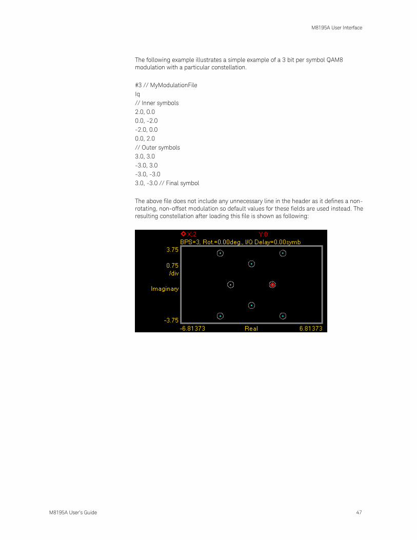
The following example illustrates a simple example of a 3 bit per symbol QAM8
modulation with a particular constellation.
#3 // MyModulationFile
Iq
// Inner symbols
2.0, 0.0
0.0, -2.0
-2.0, 0.0
0.0, 2.0
// Outer symbols
3.0, 3.0
-3.0, 3.0
-3.0, -3.0
3.0, -3.0 // Final symbol
The above file does not include any unnecessary line in the header as it defines a non-
rotating, non-offset modulation so default values for these fields are used instead. The
resulting constellation after loading this file is shown as following:

M8195A User Interface
48 M8195A User’s Guide
The following example illustrates another possible use of custom modulation to define a
distorted constellation. In this particular case, a O-QPSK modulation with a quadrature
error (non-perpendicular I and Q axis) is defined:
#2
Offset, yes
iq
1.05, 1.05
-0.95, 0.95
-1.05, -1.05
0.95, -0.95
The above file includes a line to indicate that this is an offset modulation. The resulting
constellation after loading this file is shown as following:

M8195A User Interface
M8195A User’s Guide 49
The following is a more complex example:
#3
Offset, no
Rotation, 10.0
RotMODE, cont
iq
1.0, 0.0
2.0, 0.0
0.0 ,1.0
0.0, 2.0
-1.0, 0.0
-2.0, 0.0
0.0, -1.0
0.0 ,-2.0
The above file is composed of a header with relevant information. In this particular case,
the file contains 8 (23) IQ pairs. The ‘IQ’ characters indicate the starting point for the
symbol location list composed by 8 lines with I/Q pairs separated by commas. I and Q
will not be delayed (‘Offset, no’) and constellation will rotate by 10.0 degrees (‘Rotation,
10.0’) in a continuous fashion (‘RotMODE, cont’). In fact, the ‘Offset’ and ‘RotMode’
fields could be removed without any effect on the final signal as these fields take the
default values. The resulting constellation after loading this file is shown as following:

M8195A User Interface
50 M8195A User’s Guide
2.11 Import Waveform Tab
Use this tab to perform the functions such as importing, scaling, and resampling
waveform files in a variety of formats for their generation by the M8195A arbitrary
waveform generator. It provides the controls which allow the complete definition of
signal processing parameters for the waveform file format (see File Format).
Depending on the file format and contents, marker information can be extracted and
exported to the M8195A generator. Up to two markers can be supported and assigned
to the AWG Sample and Sync markers. Also depending on the file format and contents,
information regarding the original sampling rate and/or carrier frequency of the input
waveforms can be extracted and re-used within the import tool. Resampling is
performed so no images or aliases show up in the resampled waveform.
Figure 14: Import waveform tab
This tab has the following controls and indicators:
Input File Section
File Format
For details on the available file format, see File Format.
Sample waveform data files are available in different formats as listed in the Table
4 . The files can be simply imported using the Input File section and can be sent to

M8195A User Interface
M8195A User’s Guide 51
the instrument to view the waveform preview. The sample waveform data can be
found at the location: Start > All Programs > Keysight M8195 > Keysight M8195
Examples
Steps to view the sample data file waveform preview:
1 Select the Show Next Waveform Preview check box.
2 Select the required File Format from the drop-down list.
3 Click File…
4 In the Open dialog box, select the sample waveform file (as per selected
file format)
5 Click Open.
6 Click Send to Instrument.
Table 4: Sample waveform data files
File Format Waveform Data File
TXT Sin10MHzAt64GHz.txt
BIN Sin10MHzAt64GHz.bin
BIN8 Sin10MHzAt64GHz.bin8
BIN6030 Sin10MHzAt64GHz.bin6030
BIN5110 SinDelta10MHzIQ.bin5110
IQBIN SinDelta10MHzIQ.iqbin
MAT89600 Sin10MHzAt64GHz.mat89600
CSV Sin10MHzAt64GHz.csv
DSA90000 Sin10MHzAt64GHz.dsa90000
N5110 Data With Embedded Marker Bits
This checkbox is only enabled, if the File Format is BIN5110. If checked, the
BIN5110 format with 14-bit data for I and Q and embedded marker bits is used. If
unchecked, the BIN5110 format with 16-bit data for I and Q and no marker bits is
used.
File…
Open a file selection dialog. Default file extensions match the File Format selection.
Successful loading of a waveform updates multiple information fields through the
panel reflecting the waveform settings and a graph of the waveform is shown in the
preview display.
Data Read From Input File Header Section
Sample Rate From File
Indicator only. It shows the input waveform sample rate, if any, contained in the
loaded file. If no sample rate is specified “n.a.” (not available) is shown.
Use As Source Sample Rate
This checkbox assigns the sample rate specified in the file as the Source Sample
Rate used for resampling.
Carrier Frequency From File
Indicator only. It shows the input waveform carrier frequency, if any, contained in
the loaded file. If no carrier frequency is specified “n.a.” (not available) is shown.
Data Type
This is the organization of samples within the file. It may be Single (real-only
waveform) or IQ (complex waveforms).
Spectrum Reversed

M8195A User Interface
52 M8195A User’s Guide
This checkbox is only active for complex (IQ) waveforms. It results in an imported
signal which is the complex conjugate of the input signal, thus
its spectrum will be reversed.
Data Columns
It shows the internal organization of the file regarding waveforms. It can show from
one column (Y1) up to 4 (Y1, Y2, Y3*, Y4*).
Marker Columns
It shows the internal organization of the file regarding markers. It can show from
one column (M1) up to 4 (M1, M2, M3*, M4*).
Waveform Destination Section
Channel
Independent checkboxes allowfor the definition of Multi-Tone waveforms for
Channel 1, Channel 2, Channel 3 or Channel 4. One of the boxes is always checked.
When pressing the ‘Send To Instrument’ button, the waveform is sent to all
channels that are checked.
I/Q Toggle buttons
I/Q selection toggle buttons for each channel will be shown when the a file
containing an I/Q waveform is selected for import. In-Phase (I) and Quadrature (Q)
components can be independently assigned to each channel.
Segment Number
Target segment for each channel can be defined independently. The segment
number is for future use. It is always set to Segment 1.
Resampling Section
Resampling Mode
It controls the way waveforms are imported and resampled. Please refer to the
description of the Resampling Methodology in the Appendix chapter. The following
modes are available:
None: Baseband Sample Rate will be the same as the Source Sampling
Rate. The output waveform will use the same number of samples as the
selected portion of the input waveform. Granularity requirements will be
met by repeating the basic waveform the minimum number of times so
the combined length is a multiple of the granularity for the current DAC
mode.
Timing: The time window of the input signal (Waveform Length / Sample
Rate) will be used to calculate the best value for the output record length
being a multiple of the granularity for the current DAC mode according to
the output sampling rate defined by the user. Final output sampling rate
will be slightly adjusted to accurately keep the timing of the original
signal.
M8195A User Interface
M8195A User’s Guide 53
Output_SR: The user-defined output sampling rate will be used to
calculate the best value for the output record length being a multiple of
the granularity for the current DAC mode according to the time window of
the input signal. Final time window will be slightly adjusted to keep the
selected output sampling rate. This change is reflected in the Source
Sampling Rate numeric entry field value.
Output_RL: The user-defined output Waveform Length will be used to
calculate the best value for the output Sample Rate according to the time
window of the input signal. Waveform Length will be adjusted to the
nearest multiple of the granularity for the current DAC mode according to
the time window of the input signal.
Zero_Padding: Output Waveform Length is calculated based on the input
waveform time window and the user-defined output sampling rate. The
resulting waveform length will not be, in general, a multiple of the
granularity. To meet the granularity conditions, a number of zero samples
are added until the combined number of samples is a multiple of the
granularity. Output Sample Rate will be slightly adjusted to keep the input
waveform time window.
Truncate: Output Waveform Length is calculated based on the input
waveform time window and the user-defined output sampling rate. The
resulting waveform length will not be, in general, a multiple of the
granularity. To meet the granularity conditions, a number of samples is
removed until the resulting number of samples is a multiple of the
granularity. Output Sample Rate will be slightly adjusted to keep the input
waveform time window.
Repeat: Output Waveform Length is calculated based on the input
waveform time window and the user-defined output sampling rate. The
resulting waveform length will not be, in general, a multiple of the
granularity. To meet the granularity conditions, the base waveform is
repeated the minimum number of times so the overall number of samples
is a multiple of the granularity. Output Sample Rate will be slightly
adjusted to keep the input waveform time window. The Waveform Length
field will show the length of the combined waveform.
Waveform Length
It shows the number of samples of the resampled output waveform. It can be set
when Resampling Mode is Output_RL. Otherwise, this field is an indicator.
Source Sample Rate
The speed at which samples in the input waveform are sampled. It can be set by
typing a valid value unless the "Use As Source Sample Rate" checkbox is checked.
In this particular case, the sampling rate information contained in the input
waveform file will be always used.
Baseband Sample Rate
The speed at which samples in the output waveform will be converted. It can be set
in all Resampling Modes except for the Output_RL mode.
Start Sample
This field can be used to select the starting sample of the section of the input
waveform to be imported. It cannot be set to a value higher than the Stop Sample.
Stop Sample
This field can be used to select the final sample of the section of the input
waveform to be imported. It cannot be set to a value lower than the Start Sample.
Scale
This checkbox controls the way the input output waveform will be scaled after
resampling. If unchecked, the output waveform samples will not be re-scaled.

M8195A User Interface
54 M8195A User’s Guide
Sample levels over +1.0 or under -1.0 will be clipped.
Scaling Section
DAC Max
Imported waveforms may occupy a limited range of the DAC’s full scale. This
parameter sets the maximum level. If set to a lower level than DAC Min, this will be
automatically set to the same level. Acceptable range for this parameter is -1/+1,
being the full dynamic range of the instrument’s DAC.
DAC Min
DAC Max: Imported waveforms may occupy a limited range of the DAC’s full scale.
This parameter sets the minimum level. If set to a higher level than DAC Max, this
will be automatically set to the same level. Acceptable range for this parameter is -
1/+1, being the full dynamic range of the instrument’s DAC.
Preview Section
Waveform Preview Toolbar
The waveform preview toolbar includes the icons which provide different
functionality to preview the waveform. For details, see Preview Section
Waveform Preview Toolbar.
Show Next Waveform Preview
This checkbox affects the behavior of the preview for the next waveform.
If selected, a preview of the imported waveform is displayed. Leave this checkbox
unselected to speed up the import of large waveforms.
Save To File…
Signals can be stored in files in whether BIN (for non IQ modes) or IQBIN (for IQ
modes) formats. These files may be reused within the Import Waveform tab.
Send To Instrument
Signal will be transferred to the selected segments of the selected channels. The
previous running status for the target instrument will be preserved but sampling
rate may be modified depending on the waveform requirements.
Set Default
All the imported waveform parameters are set automatically to their corresponding
default values.

M8195A User Interface
M8195A User’s Guide 55
2.12 Correction File Format
A correction file is an ASCII delimited file carrying all the information required to
compensate or embed a given frequency response in the multi-tone or complex
modulation signal. The file must be composed of a header including a series of lines
with identifiers and parameters, and a list of numerical correction factors. In lines
including more than one item (i.e., one identifier and one parameter), the items must
be separated using commas. Identifiers and parameters are not case sensitive.
These are the significant fields for the header:
InputBlockSize: It states the number of valid correction factors in the file.
It is a mandatory field.
XStart: It is frequency in Hz corresponding to the first entry in the correction
factor section of the file. It is a mandatory field for multi-tone generation in direct
mode and optional for multitone in upconverter mode and complex modulation.
XDelta: It is frequency distance in Hz between consecutive entries in the
correction factor section of the file. It is a mandatory field.
YUnit: Units for the amplitude values in the correction factor section of the file.
Parameter associated to it may be ‘dB’ (for logarithmic relative amplitudes) or ‘lin’
(for dimensionless linear relative amplitude). This parameter is optional and its
default value is ‘lin’. Phase unit must be always stated in radians.
The order of the above entries is not relevant. The correction factor section starts with
a line including a single ‘y’ or ‘Y’ character. Entries in this section are made by
Amp1(Fi), Phase1(Fi) pairs. In particular, this format is compatible with adaptive
equalizer files exported in comma-separated value (CSV) format from the Keysight
89600 VSA software package. These files reflect the channel response corrected by
the equalizer so they should be applied through the selection of the
‘Channel_Response’ option in the corresponding ‘CorrectionMode’ drop-down list in
the ‘Corrections’ section of the ‘Multi-Tone’ or ‘Complex Modulation’ panel,
respectively. Comments must start with the ‘//’ character sequence and may use a
complete line or be located at the end of any valid line. Empty lines are also valid.
This is an example correction file:
// MyCorrectionFile
InputBlockSize, 1024
XStart, 1.0E+09 // 1.0GHz
XDelta, 1.0E+06
YUnit, lin
Y
0.987, -0.2343
0.995, 0.5674
…
…
1.269, -0.765

M8195A User Interface
56 M8195A User’s Guide
The above files are is composed of a header with relevant information. In these
particular cases, the files contains 1024 linear correction factors spaced by 1 MHz and
starting at 1GHz. The ‘Y’ character indicates the starting point for the correction factor
list composed of 1024 lines with amplitude/phase pairs separated by commas. For
one-channel files Tthere is a amplitude/phase pair per line while for two channel files
there are two pairs (Amp1, Phase1, Amp2, Phase2).
The way this information is applied by the Soft Front Panel software depends on the
signal generation mode and the signal category. For direct conversion multi-tone RF
generation modes (‘Generate IQ Data’ unchecked), corrections are applied directly to
the tones based on their absolute frequency. For up-convertedmulti-tone baseband
generation(I/Q) modes (‘Generate IQ Data’ checked), corrections are applied to the
complex baseband signals. So, the internal or external carrier frequency is represented
by the central entry in the list (i.e., entry #512 in the 1024 entries example shown
above) regardless of the ‘XStart’ parameter. For Complex Modulated waveforms,
corrections are always applied to the complex baseband signals regardless of the
‘Generate IQ Data” checkbox setting so, as it happens with the correction of multi-
tone baseband signals, theinternal or external carrier frequency is represented by the
central entry in the list.
Keysight M8195A – Arbitrary Waveform Generator
User’s Guide
Keysight M8195A User’s Guide
3 General Programming
3.1 Introduction / 57
3.2 IVI-COM Programming / 58
3.3 SCPI Programming / 59
3.4 Programming Recommendations / 62
3.5 System Related Commands (SYSTem Subsystem) / 63
3.6 Common Command List / 69
3.7 Status Model / 72
3.8 :ARM/TRIGger Subsystem / 82
3.9 :INSTrument Subsystem / 82
3.10 :MMEMory Subsystem / 84
3.11 :OUTPut Subsystem / 91
3.12 Sampling Frequency Commands / 92
3.13 :VOLTage Subsystem / 93
3.14 Frequency and Phase Response Data Access / 95
3.15 :TRACe Subsystem / 95
3.16 :TEST Subsystem / 113
3.1 Introduction
Introduction The M8195A can be programmed like other modular instruments using IVI-COM
driver. In addition classic instrument programming using SCPI commands is
supported.
The following picture gives an overview about how things work together:
Programming using IVI-COM driver is not supported in revision 1.

General Programming
58 M8195A User’s Guide
Figure 15: M8195A programming
The Soft Front Panel talks to the actual M8195A module using a PCI express or USB
connection. I/O to the module is done using VISA library of Keysight I/O library.
Addressing is done with PXI resource strings, e.g. “PXI36::0::0::INSTR” or USB
resource strings, e.g. “USB-PXI0::5564::4819::DE00000001::INSTR”. The purpose of
the Soft Front Panel is to provide a classic instrument like SCPI interface that is
exposed via LAN.
IVI-COM wraps the SCPI commands into an API based programming model. To
select what module is programmed, the resource string of the module is used. The
IVI-driver will automatically locate an already running Soft Front Panel that is
handling the module. If no such Soft Front Panel exists, it is started automatically.
This way it is completely hidden that the IVI driver actually needs the Soft Front
Panel for programming the M8195A module.
VISA or VISA-COM are libraries from an installed I/O library such as the Keysight I/O
library to program the instrument using SCPI command strings. The Soft Front Panel
must be already running to connect to it.
The Soft Front Panel is also providing the user interface. It is used for interactively
changing settings. In addition, it can log what IVI or SCPI calls need to be done when
changing a setting. This can be activated with Tools Monitor Driver calls…. In
addition, you can verify changes done from a remote program.
3.2 IVI-COM Programming
The recommended way to program the M8195A module is to use the IVI drivers. See
documentation of the IVI drivers how to program using IVI drivers. The connection
between the IVI-COM driver and the Soft Front Panel is hidden. To address a module
therefore the PXI or USB resource string of the module is used. The IVI driver will
connect to an already running Soft Front Panel. If the Soft Front Panel is not running,
it will automatically start it.

General Programming
M8195A User’s Guide 59
3.3 SCPI Programming
Introduction In addition to IVI programming SCPI programming using a LAN connection is also
supported. Three LAN protocols are supported. The correct resource strings are
shown in the Soft Front Panel’s About window. A context menu is provided to copy
the resource strings.
VXI-11: The Visa resource string is e.g. “TCPIP0::localhost::inst0::INSTR”.
HiSLIP: This protocol is recommended. It offers the functionality of VXI-11
protocol with better performance that is near socket performance. Visa
resource strings look like “TCPIP0::localhost::hislip0::INSTR”. To use the HiSlip
protocol an I/O library such as the Keysight I/O Libraries Suite must be
installed. Since the protocol is new it might not be supported by the installed
I/O library. The Keysight I/O Libraries Suite 16.3 and above supports it.
However, the Keysight I/O Libraries Suite might be installed as secondary I/O
library. In this case, check if the primary I/O library supports HiSLIP. If it does
not, the socket protocol must be used.
Socket: This protocol can be used with any I/O library or using standard
operating system socket functionality connecting to port 5025. This protocol
must be used if the used I/O library is not supporting HiSLIP protocol. Visa
resource string looks like “TCPIP0::localhost::5025::SOCKET”, the exact
resource string can be seen in the Ag8195 Soft Front Panel main window.
AgM8195SFP.exe must be started prior to sending SCPI to the instrument. (See
AgM8195SFP.exe)

General Programming
60 M8195A User’s Guide
3.3.1 AgM8195SFP.exe
Before sending SCPI commands to the instrument, the Soft Front Panel
(AgM8195SFP.exe) must be started. This can be done in the Windows Start menu
(Start > All Programs > Keysight M8195 > Keysight M8195 Soft Front Panel).
3.3.1.1 Command Line Arguments
(See Communication for details about /Socket, /Telnet, /Inst, /AutoID, /NoAutoID,
/FallBack).
Table 5: Command line arguments
Option Description
/Socket socketPort Set the socket port at which the Soft Front Panel waits for SCPI commands
/Telnet telnetPort Set the telnet port at which the Soft Front Panel waits for SCPI commands
/Inst instrumentNumber Set the instrument number (instN, hislipN) at which the Soft Front Panel waits for SCPI commands
/AutoID Automatically select ports and number for the connections (default behavior).
/NoAutoID Disable the default behavior; i.e. do not automatically select ports and number for the connections.
/FallBack Try to find unused ports and number if starting a server fails.
/NoSplash Don't show the splash screen.
/r resourceName Visa PXI resource string of the module to connect to, e.g. PXI12::0::0::INSTR
General Programming
M8195A User’s Guide 61
3.3.1.2 Communication
Depending on the command line arguments /Socket, /Telnet, /Inst, /AutoID,
/NoAutoID, /FallBack, the Soft Front Panel starts several servers to handle SCPI
commands. (Refer to the table above.)
/Socket, /Telnet, /Inst: If -1, don’t start the respective servers
Defaults:
Socket port: 5025 (e.g. TCPIP0::localhost::5025::SOCKET)
Telnet port: 5024
HiSLIP, VXI-11.3: 0 (e.g. TCPIP0::localhost::hislip0::INSTR,
TCPIP0::localhost::inst0::INSTR)
/FallBack : If starting a server fails because of a conflict, try using another port or
number
HiSLIP, VXI-11.3: increase the index until a server can be started successfully
Socket, Telnet: start with port 60000, then increase it until the servers can be
started successfully. If neither socket nor telnet is disabled the Soft Front
Panel tries to start the servers on two consecutive ports
(socket port = telnet port + 1)
/AutoID : Automatically select ports and number for the connections, which are
unique per instrument.
This is the default behavior; it is not necessary to specify this argument on the
command line.
If only one AXIe module is connected to this PC and it is an M8195 module,
first try to use the command line arguments /Socket, /Telnet, /Inst, or their
respective default values if they are not specified. If starting the servers fails,
proceed with the steps below.
/Socket, /Telnet, /Inst are ignored (unless they are -1 and a server is disabled)
If the Soft Front Panel detects more than one AXIe module, use a special
mechanism to obtain a number for the HiSLIP and VXI-11.3 servers, which
makes sure that the Soft Front Panel uses always the same VISA resource
string per module
The socket and telnet port are then calculated from the HiSLIP index:
telnet port = 60000 + 2 * <HiSLIP index>
socket port = 60000 + 2 * <HiSLIP index> + 1
Note: Ports may already be in use by Windows or other applications, so they are
not available for M8195A.
/NoAutoID : Do not automatically select ports and number for the connections, use
the values specified with /Socket, /Telnet, /Inst or their respective default values
instead.
If both /NoAutoID and /AutoID are specified, /AutoID overrides /NoAutoID.
The first port not assigned by IANA is 49152 (IANA, Internet Assigned Numbers
Authority, http://www.iana.org)

General Programming
62 M8195A User’s Guide
3.4 Programming Recommendations
This section lists some recommendations for programming the instrument.
Start programming from the default setting. The common command for setting the
default setting is:
Use the binary data format when transferring waveform data.
The SCPI standard defines a long and a short form of the commands. For fast
programming speed, it is recommended to use the short forms. The short forms of
the commands are represented by upper case letters. For example the short form of
the command to set 10mV offset is:
To improve programming speed it is also allowed to skip optional subsystem
command parts. Optional subsystem command parts are depicted in square
brackets, e.g.: Set amplitude
Sufficient to use:
M8195A is a 4 channel instrument. Parameters have to be specified for output 1, 2,
3, and 4. If there is no output specified the command will set the default output 1.
So, for setting an offset of 10mV for output 1 and output 2 the commands are:
# sets offset of 10mV at output 1
# sets offset of 10mV at output 1
# sets offset of 10mV at output 2
If it is important to know whether the last command is completed then send the
common query:
It is recommended to test the new setting which will be programmed on the
instrument by setting it up manually. When you have found the correct setting, then
use this to create the program.
In the program it is recommended to send the command for starting data generation
(:INIT:IMM) as the last command. This way intermediate stop/restarts (e.g. when
changing sample rate or loading a waveform) are avoided and optimum execution
performance is achieved.
*RST # set default settings
... # other commands to set modes
... # and parameters
:OUTP1 ON # enable the output 1
:INIT:IMM # start data generation.

General Programming
M8195A User’s Guide 63
3.5 System Related Commands (SYSTem Subsystem)
3.5.1 :SYSTem:ERRor[:NEXT]?
Command :SYST:ERR?
Long :SYSTem:ERRor?
Parameters None
Parameter Suffix None
Description Read and clear one error from the instrument’s error queue.
A record of up to 30 command syntax or hardware errors can be stored in the error
queue. Errors are retrieved in first-in-first-out (FIFO) order. The first error returned is
the first error that was stored. Errors are cleared as you read them.
If more than 30 errors have occurred, the last error stored in the queue (the most
recent error) is replaced with “Queue overflow”. No additional errors are stored until
you remove errors from the queue.
If no errors have occurred when you read the error queue, the instrument responds
with 0,“No error”.
The error queue is cleared by the command, when the power is cycled, or
when the Soft Front Panel is re-started.
The error queue is not cleared by a reset ( ) command.
The error messages have the following format (the error string may contain up to 255
characters):
error number,”Description”, e.g.
-113,”Undefined header”.
Example Query
:SYST:ERR?
3.5.2 :SYSTem:HELP:HEADers?
Command :SYST:HELP:HEAD?
Long :SYSTem:HELP:HEADers?
Parameters None
Parameter Suffix None

General Programming
64 M8195A User’s Guide
Description The HEADers? query returns all SCPI commands and queries and IEEE 488.2
common commands and common queries implemented by the instrument. The
response is a <DEFINITE LENGTH ARBITRARY BLOCK RESPONSE DATA> element.
The full path for every command and query is returned separated by linefeeds. The
syntax of the response is defined as: The <nonzero digit> and sequence of <digit>
follow the rules in IEEE 488.2, Section 8.7.9. A <SCPI header> is defined as: It
contains all the nodes from the root. The <SCPI program mnemonic> contains the
node in standard SCPI format. The short form uses uppercase characters while the
additional characters for the long form are in lowercase characters. Default nodes
are surrounded by square brackets ([]).
Example Query
:SYST:HELP:HEAD?

General Programming
M8195A User’s Guide 65
3.5.3 :SYSTem:LICense:EXTended:LIST?
Command :SYST:LIC:EXT:LIST?
Long :SYSTem:LICense:EXTended:LIST?
Parameters None
Parameter Suffix None
Description This query lists the licenses installed.
Example Query
:SYST:LIC:EXT:LIST?
3.5.4 :SYSTem:SET[?]
Command :SYST:SET[?]
Long :SYSTem:SET[?]
Parameters <binary block data>
Parameter Suffix None
Description In query form, the command reads a block of data containing the instrument’s
complete set-up. The set-up information includes all parameter and mode settings,
but does not include the contents of the instrument setting memories or the status
group registers. The data is in a binary format, not ASCII, and cannot be edited.
In set form, the block data must be a complete instrument set-up read using the
query form of the command.
This command has the same functionality as the command.
Example Command
:SYST:SET <binary block data>
Query
:SYST:SET?
3.5.5 :SYSTem:VERSion?
Command :SYST:VERS?
Long :SYSTem:VERSion?
Parameters None

General Programming
66 M8195A User’s Guide
Parameter Suffix None
Description This query returns a formatted numeric value corresponding to the SCPI version
number for which the instrument complies.
Example Query
:SYST:VERS?
3.5.6 :SYSTem:COMMunicate:*?
Command :SYST:COMM:*?
Long :SYSTem:COMMunicate:*?
Parameters None
Parameter Suffix None
Description These queries return information about the instrument Soft Front Panel’s available
connections. If a connection is not available, the returned value is -1.
This is only useful if there is more than one Keysight module connected to a PC,
otherwise one would normally use the default connections (HiSLIP and VXI-11
instrument number 0, socket port 5025, telnet port 5024)
One can never be sure if a socket port is already in use, so one could e.g. specify a
HiSLIP number on the command line
and let the Soft Front Panel find an unused socket port. Then
this socket port can be queried using the HiSLIP connection.
Example Query
:SYST:COMM:*?

General Programming
M8195A User’s Guide 67
3.5.6.1 :SYSTem:COMMunicate:INSTr[:NUMBer]?
Command :SYST:COMM:INST?
Long :SYSTem:COMMunicate:INSTr?
Parameters None
Parameter Suffix None
Description This query returns the VXI-11 instrument number used by the Soft Front Panel.
Example Query
:SYST:COMM:INST?
3.5.6.2 :SYSTem:COMMunicate:HISLip[:NUMBer]?
Command :SYST:COMM:HISL?
Long :SYSTem:COMMunicate:HISLip?
Parameters None
Parameter Suffix None
Description This query returns the HiSLIP number used by the Soft Front Panel.
Example Query
:SYST:COMM:HISL?
3.5.6.3 :SYSTem:COMMunicate:SOCKet[:PORT]?
Command :SYST:COMM:SOCK?
Long :SYSTem:COMMunicate:SOCKet?
Parameters None
Parameter Suffix None
Description This query returns the socket port used by the Soft Front Panel.
Example Query
:SYST:COMM:SOCK?

General Programming
68 M8195A User’s Guide
3.5.6.4 :SYSTem:COMMunicate:TELNet[:PORT]?
Command :SYST:COMM:TELN?
Long :SYSTem:COMMunicate:TELNet?
Parameters None
Parameter Suffix None
Description This query returns the telnet port used by the Soft Front Panel.
Example Query
:SYST:COMM:TELN?
3.5.6.5 :SYSTem:COMMunicate:TCPip:CONTrol?
Command :SYST:COMM:TCP:CONT?
Long :SYSTem:COMMunicate:TCPip:CONTrol?
Parameters None
Parameter Suffix None
Description This query returns the port number of the control connection. You can use the
control port to send control commands (for example “Device Clear”) to the
instrument.
Example Query
:SYST:COMM:TCP:CONT?
General Programming
M8195A User’s Guide 69
3.6 Common Command List
3.6.1 *IDN?
Read the instrument’s identification string which contains four fields separated by
commas. The first field is the manufacturer’s name, the second field is the model
number, the third field is the serial number, and the fourth field is a revision code
which contains four numbers separated dots and a fifth number separated by a dash:
Keysight Technologies, M8195A,<serial number>, x.x.x.x-h
x.x.x.x= Soft Front Panel revision number, e.g. 2.0.0.0
h= Hardware revision number
3.6.2 *CLS
Clear the event register in all register groups. This command also clears the error
queue and cancels a *OPC operation. It doesn’t clear the enable register.
3.6.3 *ESE
Enable bits in the Standard Event Status Register to be reported in the Status Byte.
The selected bits are summarized in the “Standard Event” bit (bit 5) of the Status
Byte Register. The *ESE? query returns a value which corresponds to the binary-
weighted sum of all bits enabled decimal by the *ESE command. These bits are not
cleared by a *CLS command. Value Range: 0–255.

General Programming
70 M8195A User’s Guide
3.6.4 ESR?
Query the Standard Event Status Register. Once a bit is set, it remains set until
cleared by a *CLS (clear status) command or queried by this command. A query of
this register returns a decimal value which corresponds to the binary-weighted sum
of all bits set in the register.
3.6.5 *OPC
Set the “Operation Complete” bit (bit 0) in the Standard Event register after the
previous commands have been completed.
3.6.6 *OPC?
Return “1” to the output buffer after the previous commands have been completed.
Other commands cannot be executed until this command completes.
3.6.7 *OPT?
Read the installed options. The response consists of any number of fields separated
by commas.
3.6.8 *RST
Reset instrument to its factory default state.
General Programming
M8195A User’s Guide 71
3.6.9 *SRE[?]
Enable bits in the Status Byte to generate a Service Request. To enable specific bits,
you must write a decimal value which corresponds to the binary-weighted sum of the
bits in the register. The selected bits are summarized in the “Master Summary” bit
(bit 6) of the Status Byte Register. If any of the selected bits change from “0” to “1”, a
Service Request signal is generated. The query returns a decimal value which
corresponds to the binary-weighted sum of all bits enabled by the command.
3.6.10 *STB?
Query the summary (status byte condition) register in this register group. This
command is similar to a Serial Poll but it is processed like any other instrument
command. This command returns the same result as a Serial Poll but the “Master
Summary” bit (bit 6) is not cleared by the command.
3.6.11 *TST?
Execute Self Tests. If self-tests pass, a 0 is returned. A number lager than 0 indicates
the number of failed tests.
To get actual messages, use :
3.6.12 *LRN?
Query the instrument and return a binary block of data containing the current
settings (learn string). You can then send the string back to the instrument to restore
this state later. For proper operation, do not modify the returned string before
sending it to the instrument. Use to send the learn string. See
:SYSTem:SET[?].
3.6.13 *WAI?
Prevents the instrument from executing any further commands until the current
command has finished executing.

General Programming
72 M8195A User’s Guide
3.7 Status Model
Introduction This section describes the structure of the SCPI status system used by the M8195A.
The status system records various conditions and states of the instrument in several
register groups as shown on the following pages. Each of the register groups is made
up of several low level registers called Condition registers, Event registers, and
Enable registers which control the action of specific bits within the register group.
These groups are explained below:
A condition register continuously monitors the state of the instrument. The
bits in the condition register are updated in real time and the bits are not
latched or buffered. This is a read-only register and bits are not cleared when
you read the register. A query of a condition register returns a decimal value
which corresponds to the binary-weighted sum of all bits set in that register.
An event register latches the various events from changes in the condition
register. There is no buffering in this register; while an event bit is set,
subsequent events corresponding to that bit are ignored. This is a read only
register. Once a bit is set, it remains set until cleared by query command
(such as ) or a (clear status) command. A query of
this register returns a decimal value which corresponds to the binary-
weighted sum of all bits set in that register.
An enable register defines which bits in the event register will be reported to
the Status Byte register group. You can write to or read from an enable
register. A (clear status) command will not clear the enable register but
it does clear all bits in the event register. A command clears all
bits in the enable register. To enable bits in the enable register to be reported
to the Status Byte register, you must write a decimal value which corresponds
to the binary weighted sum of the corresponding bits.
Transition Filters are used to detect changes of the state in the condition
register and set the corresponding bit in the event register. You can set
transition filter bits to detect positive transitions (PTR), negative transitions
(NTR) or both. Transition filters are read/write registers. They are not affected
by .

General Programming
M8195A User’s Guide 73
Figure 16: Status register structure

General Programming
74 M8195A User’s Guide
3.7.1 :STATus:PRESet
Clears all status group event registers. Presets the status group enables PTR and
NTR registers as follows:
ENABle = 0x0000, PTR = 0xffff, NTR = 0x0000
3.7.2 Status Byte Register
The Status Byte summary register reports conditions from the other status registers.
Data that is waiting in the instrument’s output buffer is immediately reported on the
“Message Available” bit (bit 4) for example. Clearing an event register from one of the
other register groups will clear the corresponding bits in the Status Byte condition
register. Reading all messages from the output buffer, including any pending queries,
will clear the “Message Available” bit. To set the enable register mask and generate
an SRQ (service request), you must write a decimal value to the register using the
command.
Table 6: Status byte register
Bit Number Decimal Value Definition
0 Not used 1 Not Used. Returns “0”
1 Not used 2 Not Used. Returns “0”
2 Error Queue 4 One or more error are stored in the Error Queue
3 Questionable Data 8 One or more bits are set in the Questionable Data Register (bits must be
enabled)
4 Message Available 16 Data is available in the instrument’s output buffer
5 Standard Event 32 One or more bits are set in the Standard Event Register
6 Master Summary 64 One or more bits are set in the Status Byte Register
7 Operational Data 128 One or more bits set in the Operation Data Register (bits must be enabled)

General Programming
M8195A User’s Guide 75
3.7.3 Questionable Data Register Command Subsystem
The Questionable Data register group provides information about the quality or
integrity of the instrument. Any or all of these conditions can be reported to the
Questionable Data summary bit through the enable register.
Table 7: Questionable data register
Bit Number Decimal Value Definition
0 Voltage warning 1 Output has been switched off (to protect itself)
1 Not used 2 Returns “0”
2 Not used 4 Returns “0”
3 Not used 8 Returns “0”
4 Not used 16 Returns “0”
5 Not used 32 Returns “0”
6 Not used 64 Returns “0”
7 USB disconnected 128 USB module connection state
8 Not used 256 Returns “0”
9 Not used 512 Returns “0”
10 Not used 1024 Returns “0”
11 Not used 2048 Returns “0”
12 Not used 4096 Returns “0”
13 Not used 8192 Returns “0”
14 Not used 16384 Returns “0”
15 Not used 32768 Returns “0”

General Programming
76 M8195A User’s Guide
The following commands access the questionable status group.
3.7.3.1 :STATus:QUEStionable[:EVENt]?
Reads the event register in the questionable status group. It’s a read-only register.
Once a bit is set, it remains set until cleared by this command or the
command. A query of the register returns a decimal value which corresponds to the
binary-weighted sum of all bits set in the register.
3.7.3.2 :STATus:QUEStionable:CONDition?
Reads the condition register in the questionable status group. It’s a read-only
register and bits are not cleared when you read the register. A query of the register
returns a decimal value which corresponds to the binary-weighted sum of all bits set
in the register.
3.7.3.3 :STATus:QUEStionable:ENABle[?]
Sets or queries the enable register in the questionable status group. The selected
bits are then reported to the Status Byte. A will not clear the enable register
but it does clear all bits in the event register. To enable bits in the enable register,
you must write a decimal value which corresponds to the binary-weighted sum of the
bits you wish to enable in the register.
3.7.3.4 :STATus:QUEStionable:NTRansition[?]
Sets or queries the negative-transition register in the questionable status group. A
negative transition filter allows an event to be reported when a condition changes
from true to false. Setting both positive/negative filters true allows an event to be
reported anytime the condition changes. Clearing both filters disable event reporting.
The contents of transition filters are unchanged by and .
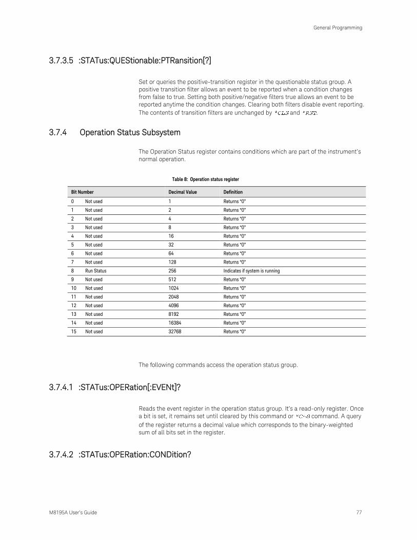
General Programming
M8195A User’s Guide 77
3.7.3.5 :STATus:QUEStionable:PTRansition[?]
Set or queries the positive-transition register in the questionable status group. A
positive transition filter allows an event to be reported when a condition changes
from false to true. Setting both positive/negative filters true allows an event to be
reported anytime the condition changes. Clearing both filters disable event reporting.
The contents of transition filters are unchanged by and .
3.7.4 Operation Status Subsystem
The Operation Status register contains conditions which are part of the instrument’s
normal operation.
Table 8: Operation status register
Bit Number Decimal Value Definition
0 Not used 1 Returns “0”
1 Not used 2 Returns “0”
2 Not used 4 Returns “0”
3 Not used 8 Returns “0”
4 Not used 16 Returns “0”
5 Not used 32 Returns “0”
6 Not used 64 Returns “0”
7 Not used 128 Returns “0”
8 Run Status 256 Indicates if system is running
9 Not used 512 Returns “0”
10 Not used 1024 Returns “0”
11 Not used 2048 Returns “0”
12 Not used 4096 Returns “0”
13 Not used 8192 Returns “0”
14 Not used 16384 Returns “0”
15 Not used 32768 Returns “0”
The following commands access the operation status group.
3.7.4.1 :STATus:OPERation[:EVENt]?
Reads the event register in the operation status group. It’s a read-only register. Once
a bit is set, it remains set until cleared by this command or command. A query
of the register returns a decimal value which corresponds to the binary-weighted
sum of all bits set in the register.
3.7.4.2 :STATus:OPERation:CONDition?

General Programming
78 M8195A User’s Guide
Reads the condition register in the operation status group. It’s a read-only register
and bits are not cleared when you read the register. A query of the register returns a
decimal value which corresponds to the binary-weighted sum of all bits set in the
register.
3.7.4.3 :STATus:OPERation:ENABle[?]
Sets or queries the enable register in the operation status group. The selected bits
are then reported to the Status Byte. A will not clear the enable register but it
does clear all bits in the event register. To enable bits in the enable register, you
must write a decimal value which corresponds to the binary-weighted sum of the bits
you wish to enable in the register.
3.7.4.4 :STATus:OPERation:NTRansition[?]
Sets or queries the negative-transition register in the operation status group. A
negative transition filter allows an event to be reported when a condition changes
from true to false. Setting both positive/negative filters true allows an event to be
reported anytime the condition changes. Clearing both filters disable event reporting.
The contents of transition filters are unchanged by and .
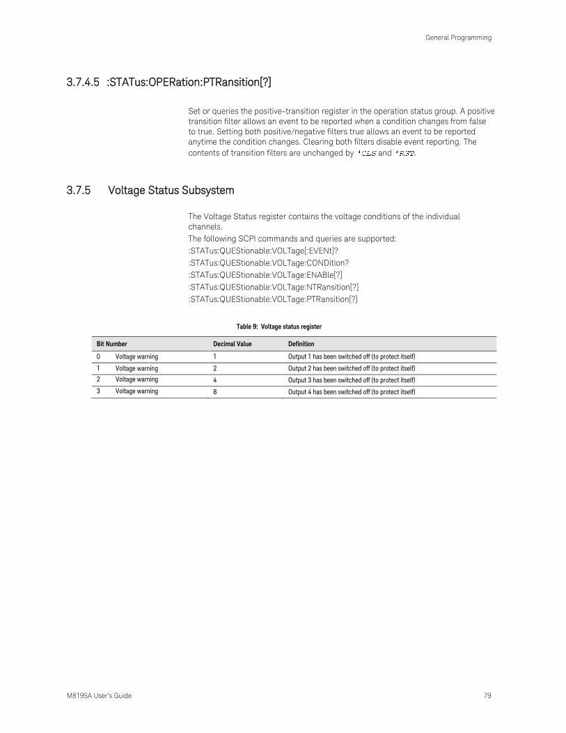
General Programming
M8195A User’s Guide 79
3.7.4.5 :STATus:OPERation:PTRansition[?]
Set or queries the positive-transition register in the operation status group. A positive
transition filter allows an event to be reported when a condition changes from false
to true. Setting both positive/negative filters true allows an event to be reported
anytime the condition changes. Clearing both filters disable event reporting. The
contents of transition filters are unchanged by and .
3.7.5 Voltage Status Subsystem
The Voltage Status register contains the voltage conditions of the individual
channels.
The following SCPI commands and queries are supported:
:STATus:QUEStionable:VOLTage[:EVENt]?
:STATus:QUEStionable:VOLTage:CONDition?
:STATus:QUEStionable:VOLTage:ENABle[?]
:STATus:QUEStionable:VOLTage:NTRansition[?]
:STATus:QUEStionable:VOLTage:PTRansition[?]
Table 9: Voltage status register
Bit Number Decimal Value Definition
0 Voltage warning 1 Output 1 has been switched off (to protect itself)
1 Voltage warning 2 Output 2 has been switched off (to protect itself)
2 Voltage warning 4 Output 3 has been switched off (to protect itself)
3 Voltage warning 8 Output 4 has been switched off (to protect itself)

General Programming
80 M8195A User’s Guide
3.7.6 Connection Status Subsystem
The Connection Status register contains the state of the USB connection to the
M8195A module.
The following SCPI commands and queries are supported:
:STATus:QUEStionable:CONNection[:EVENt]?
:STATus:QUEStionable:CONNection:CONDition?
:STATus:QUEStionable:CONNection:ENABle[?]
:STATus:QUEStionable:CONNection:NTRansition[?]
:STATus:QUEStionable:CONNection:PTRansition[?]
Table 10: Connection status register
Bit Number Decimal Value Definition
0 USB disconnected 1 USB module connection state

General Programming
M8195A User’s Guide 81
3.7.7 Run Status Subsystem
The Run Status register contains the run status conditions of the individual channels.
The following SCPI commands and queries are supported:
:STATus:OPERation:RUN[:EVENt]?
:STATus:OPERation:RUN:CONDition?
:STATus:OPERation:RUN:ENABle[?]
:STATus:OPERation:RUN:NTRansition[?]
:STATus:OPERation:RUN:PTRansition[?]
Table 11: Run status register
Bit Number Decimal Value Definition
0 Run Status 1 Indicates if channel 1 is running
1 Run Status 2 Indicates if channel 2 is running
2 Run Status 4 Indicates if channel 3 is running
3 Run Status 8 Indicates if channel 4 is running

General Programming
82 M8195A User’s Guide
3.8 :ARM/TRIGger Subsystem
3.8.1 :ABORt[1|2|3|4]
Command :ABOR[1|2|3|4]
Long :ABORt[1|2|3|4]
Parameters None
Parameter Suffix None
Description Stop signal generation on all channels. The channel suffix is ignored.
Example Command
:ABOR1
3.8.2 :INITiate:IMMediate[1|2|3|4]
Command :INIT:IMM[1|2|3|4]
Long :INITiate:IMMediate[1|2|3|4]
Parameters None
Parameter Suffix None
Description Start signal generation on all channels. The channel suffix is ignored
Example Command
:INIT:IMM
3.9 :INSTrument Subsystem
3.9.1 :INSTrument:SLOT[:NUMBer]?
Command :INST:SLOT?
Long :INSTrument:SLOT?
Parameters None

General Programming
M8195A User’s Guide 83
Parameter Suffix None
Description Query the instrument’s slot number in its AXIe frame.
Example Query
:INST:SLOT?
3.9.2 :INSTrument:IDENtify [<seconds>]
Command :INST:IDEN
Long :INSTrument:IDENtify
Parameters <seconds>
Parameter Suffix None
Description Identify the instrument by flashing the green “Access” LED on the front panel for a
certain time.
<seconds> optional length of the flashing interval, default is 10 seconds.
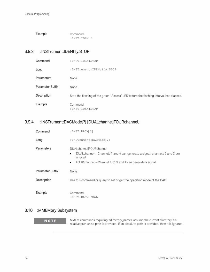
General Programming
84 M8195A User’s Guide
Example Command
:INST:IDEN 5
3.9.3 :INSTrument:IDENtify:STOP
Command :INST:IDEN:STOP
Long :INSTrument:IDENtify:STOP
Parameters None
Parameter Suffix None
Description Stop the flashing of the green “Access” LED before the flashing interval has elapsed.
Example Command
:INST:IDEN:STOP
3.9.4 :INSTrument:DACMode[?] [DUALchannel|FOURchannel]
Command :INST:DACM[?]
Long :INSTrument:DACMode[?]
Parameters DUALchannel|FOURchannel
DUALchannel – Channels 1 and 4 can generate a signal, channels 2 and 3 are
unused
FOURchannel – Channel 1, 2, 3 and 4 can generate a signal
Parameter Suffix None
Description Use this command or query to set or get the operation mode of the DAC.
Example Command
:INST:DACM DUAL
3.10 :MMEMory Subsystem
MMEM commands requiring <directory_name> assume the current directory if a
relative path or no path is provided. If an absolute path is provided, then it is ignored.
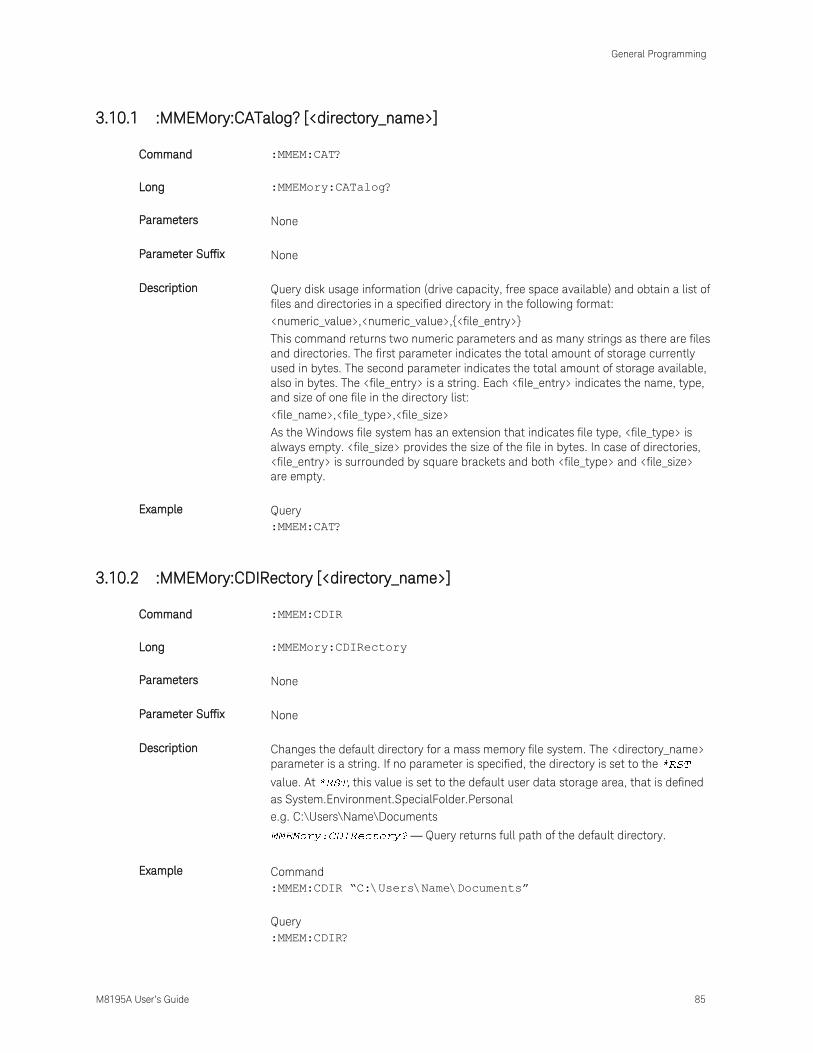
General Programming
M8195A User’s Guide 85
3.10.1 :MMEMory:CATalog? [<directory_name>]
Command :MMEM:CAT?
Long :MMEMory:CATalog?
Parameters None
Parameter Suffix None
Description Query disk usage information (drive capacity, free space available) and obtain a list of
files and directories in a specified directory in the following format:
<numeric_value>,<numeric_value>,{<file_entry>}
This command returns two numeric parameters and as many strings as there are files
and directories. The first parameter indicates the total amount of storage currently
used in bytes. The second parameter indicates the total amount of storage available,
also in bytes. The <file_entry> is a string. Each <file_entry> indicates the name, type,
and size of one file in the directory list:
<file_name>,<file_type>,<file_size>
As the Windows file system has an extension that indicates file type, <file_type> is
always empty. <file_size> provides the size of the file in bytes. In case of directories,
<file_entry> is surrounded by square brackets and both <file_type> and <file_size>
are empty.
Example Query
:MMEM:CAT?
3.10.2 :MMEMory:CDIRectory [<directory_name>]
Command :MMEM:CDIR
Long :MMEMory:CDIRectory
Parameters None
Parameter Suffix None
Description Changes the default directory for a mass memory file system. The <directory_name>
parameter is a string. If no parameter is specified, the directory is set to the
value. At , this value is set to the default user data storage area, that is defined
as System.Environment.SpecialFolder.Personal
e.g. C:\Users\Name\Documents
— Query returns full path of the default directory.
Example Command
:MMEM:CDIR “C:\Users\Name\Documents”
Query
:MMEM:CDIR?

General Programming
86 M8195A User’s Guide
3.10.3 :MMEMory:COPY <string>,<string>[,<string>,<string>]
Command :MMEM:COPY
Long :MMEMory:COPY
Parameters <string>,<string>
Parameter Suffix None
Description Copies an existing file to a new file or an existing directory to a new directory. Two
forms of parameters are allowed. The first form has two parameters. In this form, the
first parameter specifies the source, and the second parameter specifies the
destination.
The second form has four parameters. In this form, the first and third parameters
specify the file names. The second and fourth parameters specify the directories. The
first pair of parameters specifies the source. The second pair specifies the
destination. An error is generated if the source doesn't exist or the destination file
already exists.
Example Command
:MMEM:COPY "C:\data.txt", "C:\data_new.txt"

General Programming
M8195A User’s Guide 87
3.10.4 :MMEMory:DELete <file_name>[,<directory_name>]
Command :MMEM:DEL
Long :MMEMory:DELete
Parameters <file_name>
Parameter Suffix None
Description Removes a file from the specified directory. The <file_name> parameter specifies the
file to be removed.
Example Command
:MMEM:DEL "C:\data.txt"
3.10.5 :MMEMory:DATA <file_name>, <data>
Command :MMEM:DATA
Long :MMEMory:DATA
Parameters <file_name>, <data>
Parameter Suffix None
Description The command form is . It loads <data>
into the file <file_name>. <data> is in 488.2 block format. <file_name> is string data.

General Programming
88 M8195A User’s Guide
Example Command
:MMEM:DATA “C:\data.txt”, #14test
3.10.6 :MMEMory:DATA? <file_name>
Command :MMEM:DATA?
Long :MMEMory:DATA?
Parameters <file_name>
Parameter Suffix None
Description The query form is > with the response being the
associated <data> in block format.
Example Query
:MMEM:DATA? "C:\data.txt"
3.10.7 :MMEMory:MDIRectory <directory_name>
Command :MMEM:MDIR
Long :MMEMory:MDIRectory
Parameters <directory_name>
Parameter Suffix None
Description Creates a new directory. The <directory_name> parameter specifies the name to be
created.
Example Command
:MMEM:MDIR "C:\data_dir"
3.10.8 :MMEMory:MOVE <string>,<string>[,<string>,<string>]
Command :MMEM:MOVE
Long :MMEMory:MOVE
Parameters <string>,<string>
Parameter Suffix None
Description Moves an existing file to a new file or an existing directory to a new directory. Two
forms of parameters are allowed. The first form has two parameters. In this form, the
first parameter specifies the source, and the second parameter specifies the
destination.
The second form has four parameters. In this form, the first and third parameters
specify the file names. The second and fourth parameters specify the directories. The
first pair of parameters specifies the source. The second pair specifies the
destination. An error is generated if the source doesn't exist or the destination file
already exists.

General Programming
M8195A User’s Guide 89
Example Command
:MMEM:MOVE "C:\data_dir","C:\newdata_dir"

General Programming
90 M8195A User’s Guide
3.10.9 :MMEMory:RDIRectory <directory_name>
Command :MMEM:RDIR
Long :MMEMory:RDIRectory
Parameters <directory_name >
Parameter Suffix None
Description Removes a directory. The <directory_name> parameter specifies the directory name
to be removed. All files and directories under the specified directory are also
removed.
Example Command
:MMEM:RDIR "C:\newdata_dir"
3.10.10 :MMEMory:LOAD:CSTate <file_name>
Command :MMEM:LOAD:CST
Long :MMEMory:LOAD:CSTate
Parameters <file_name >
Parameter Suffix None
Description Current state of instrument is loaded from a file.
Example Command
:MMEM:LOAD:CST "C:\data.txt"
3.10.11 :MMEMory:STORe:CSTate <file_name>
Command :MMEM:STOR:CST
Long :MMEMory:STORe:CSTate
Parameters <file_name >
Parameter Suffix None
Description Current state of instrument is stored to a file.
Example Command
:MMEM:STOR:CST "C:\data.txt"

General Programming
M8195A User’s Guide 91
3.11 :OUTPut Subsystem
3.11.1 :OUTPut[1|2|3|4][:STATe][?] OFF|ON|0|1
Command :OUTP[?]
Long :OUTPut[?]
Parameters OFF|ON|0|1
Parameter Suffix None
Description Switch the amplifier of the output path for a channel on or off.
Example Command
:OUTP ON
Query
:OUTP?
General Programming
92 M8195A User’s Guide
3.12 Sampling Frequency Commands
3.12.1 [:SOURce]:FREQuency:RASTer[?] <frequency>|MINimum|MAXimum
Command :FREQ:RAST[?]
Long :FREQuency:RASTer[?]
Parameters <frequency>|MINimum|MAXimum
Parameter Suffix None
Description Set or query the sample frequency of the output DAC. of
Example Command
:FREQ:RAST MIN
Query
:FREQ:RAST?

General Programming
M8195A User’s Guide 93
3.13 :VOLTage Subsystem
Set the output voltages for a channel.
3.13.1 [:SOURce]:VOLTage[1|2|3|4][:LEVel][:IMMediate][:AMPLitude][?] <level>
Command :VOLT[?]
Long :VOLTage[?]
Parameters <level>
Parameter Suffix None
Description Set or query the output amplitude.
Example Command
:VOLT 0.685
Query
:VOLT?

General Programming
94 M8195A User’s Guide
3.13.2 [:SOURce]:VOLTage[1|2|3|4][:LEVel][:IMMediate]:OFFSet[?] <level>
Command :VOLT:OFFS[?]
Long :VOLTage:OFFSet[?]
Parameters <level>
Parameter Suffix None
Description Set or query the output offset.
Example Command
:VOLT:OFFS 0.02
Query
:VOLT:OFFS?
3.13.3 [:SOURce]:VOLTage[1|2|3|4][:LEVel][:IMMediate]:HIGH[?] <level>
Command :VOLT:HIGH[?]
Long :VOLTage:HIGH[?]
Parameters <level>
Parameter Suffix None
Description Set or query the output high level.
Example Command
:VOLT:HIGH 3e-1
Query
:VOLT:HIGH?
3.13.4 [:SOURce]:VOLTage[1|2|3|4][:LEVel][:IMMediate]:LOW[?] <level>
Command :VOLT:LOW[?]
Long :VOLTage:LOW[?]
Parameters <level>
Parameter Suffix None
Description Set or query the output low level.
Example Command
:VOLT:LOW -0.3
Query
:VOLT:LOW?
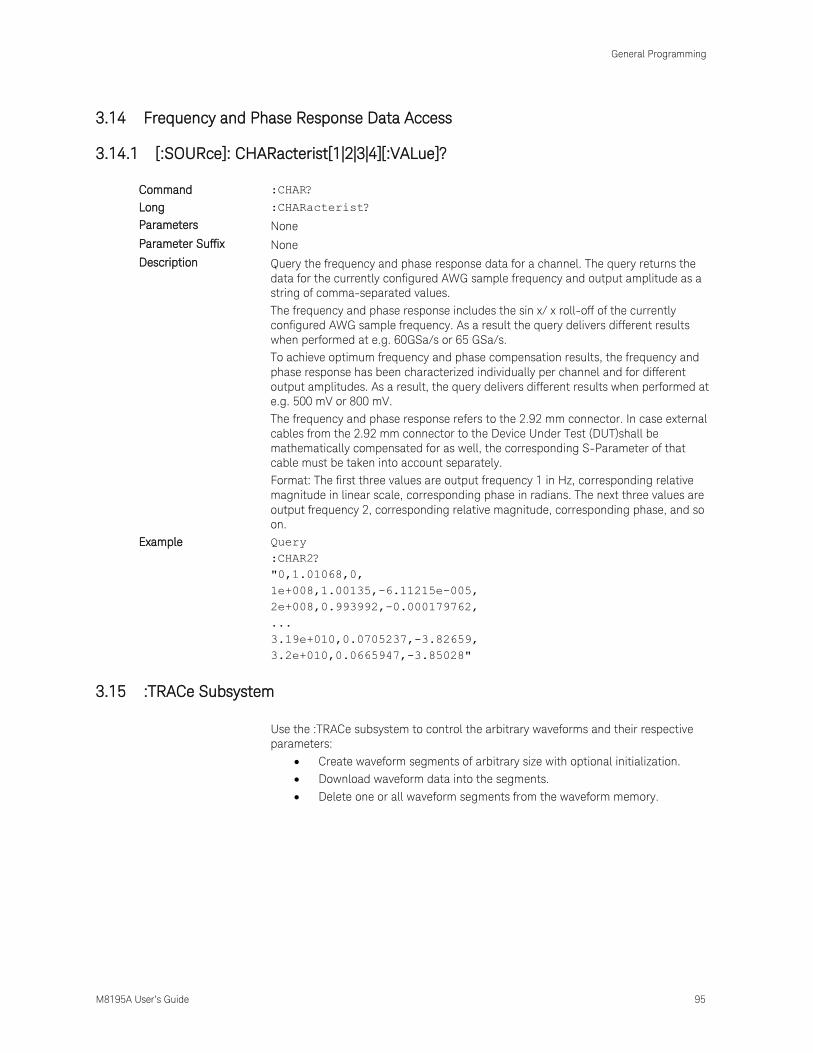
General Programming
M8195A User’s Guide 95
3.14 Frequency and Phase Response Data Access
3.14.1 [:SOURce]: CHARacterist[1|2|3|4][:VALue]?
Command :CHAR?
Long :CHARacterist?
Parameters None
Parameter Suffix None
Description Query the frequency and phase response data for a channel. The query returns the
data for the currently configured AWG sample frequency and output amplitude as a
string of comma-separated values.
The frequency and phase response includes the sin x/ x roll-off of the currently
configured AWG sample frequency. As a result the query delivers different results
when performed at e.g. 60GSa/s or 65 GSa/s.
To achieve optimum frequency and phase compensation results, the frequency and
phase response has been characterized individually per channel and for different
output amplitudes. As a result, the query delivers different results when performed at
e.g. 500 mV or 800 mV.
The frequency and phase response refers to the 2.92 mm connector. In case external
cables from the 2.92 mm connector to the Device Under Test (DUT)shall be
mathematically compensated for as well, the corresponding S-Parameter of that
cable must be taken into account separately.
Format: The first three values are output frequency 1 in Hz, corresponding relative
magnitude in linear scale, corresponding phase in radians. The next three values are
output frequency 2, corresponding relative magnitude, corresponding phase, and so
on.
Example Query
:CHAR2?
"0,1.01068,0,
1e+008,1.00135,-6.11215e-005,
2e+008,0.993992,-0.000179762,
...
3.19e+010,0.0705237,-3.82659,
3.2e+010,0.0665947,-3.85028"
3.15 :TRACe Subsystem
Use the :TRACe subsystem to control the arbitrary waveforms and their respective
parameters:
Create waveform segments of arbitrary size with optional initialization.
Download waveform data into the segments.
Delete one or all waveform segments from the waveform memory.

General Programming
96 M8195A User’s Guide
3.15.1 Waveform Memory Capacity
The available waveform memory is 256K (262144) samples per channel.
3.15.2 Waveform Length Granularity and Size
The waveform length granularity is 128. The minimum waveform size is 128 samples.
The maximum size is equal the complete size of the waveform memory.
3.15.3 Waveform Data Format
In the data formats shown below the fields have the following meanings:
DB7…DB0 - Sample as signed 8-bit value, valid range is -128 to +127.
Samples Format 7 6 5 4 3 2 1 0
DB7 DB6 DB5 DB4 DB3 DB2 DB1 DB0

General Programming
M8195A User’s Guide 97
3.15.4 Arbitrary Waveform Generation
To prepare your module for arbitrary waveform generation follow these steps:
Define a segment using the various forms of the
:TRAC[1|2|3|4]:DEF command.
Fill the segment with sample values using
:TRAC[1|2|3|4]:DATA.
Signal generation starts after calling INIT:IMM.
The waveforms in different channels must have the same lengths. If two or more
channels contain differing waveform lengths, an error is returned when trying to start
signal generation.
Use the :TRAC[1|2|3|4]:CAT? query to read the length of a waveform loaded into the
memory of a channel. Use the :TRAC[1|2|3|4]:DEL:ALL command to delete a
waveform from the memory of a channel.

General Programming
98 M8195A User’s Guide
3.15.5 :TRAC[1|2|3|4]:DEF
Command :TRAC[1|2|3|4]:DEF
Long :TRACe[1|2|3|4]:DEFine
Parameters <segment_id>,<length>[,<init_value>]
<segment_id > – id of the segment, must be 1
<length> – length of the segment in samples
<init_value> – optional initialization DAC value
Parameter Suffix None
Description Use this command to define the size of a waveform memory segment. If <init_value>
is specified, all values in the segment are initialized. If not specified, memory is only
allocated but not initialized.
Example Commands
Define a segment with id 1 and length 1280 samples on channel 1. Initialize all
samples to 0.
TRAC1:DEF 1,1280,0

General Programming
M8195A User’s Guide 99
3.15.6 :TRAC[1|2|3|4]:DEF:NEW?
Command :TRAC[1|2|3|4]:DEF:NEW?
Long :TRACe[1|2|3|4]:DEFine:NEW?
Parameters <length> [,<init_value>]
<length> – length of the segment in samples
<init_value> – optional initialization DAC value
Parameter Suffix None
Description Use this query to define the size of a waveform memory segment. If <init_value> is
specified, all values in the segment are initialized. If not specified, memory is only
allocated but not initialized. If the query was successful, a new <segment_id> will be
returned.
Example Query
Define a segment of length 1280 samples on channel 1. Returns the segment id.
TRAC1:DEF:NEW? 1280

General Programming
100 M8195A User’s Guide
3.15.7 :TRAC[1|2|3|4]:DEF:WONL
Command :TRAC[1|2|3|4]:DEF:WONL
Long :TRACe[1|2|3|4]:DEFine:WONLy
Parameters <segment_id>,<length>[,<init_value>]
< segment_id > – id of the segment, must be 1
<length> – length of the segment in samples
<init_value> – optional initialization DAC value.
Parameter Suffix None
Description Use this command to define the size of a waveform memory segment. If <init_value>
is specified, all values in the segment are initialized. If not specified, memory is only
allocated but not initialized. The segment will be flagged write-only, so it cannot be
read back or stored.
Example Command
Define a write-only segment with id 1 and length 1280 samples on channel 1.
:TRAC1:DEF:WONL 1,1280

General Programming
M8195A User’s Guide 101
3.15.8 :TRAC[1|2|3|4]:DEF:WONL:NEW?
Command :TRAC[1|2|3|4]:DEF:WONL:NEW?
Long :TRACe[1|2|3|4]:DEFine:WONLy:NEW?
Parameters <length>[,<init_value>]
<length> – length of the segment in samples
<init_value> – optional initialization DAC value
Parameter Suffix None
Description Use this query to define the size of a waveform memory segment. If <init_value> is
specified, all sample values in the segment are initialized. If not specified, memory is
only allocated but not initialized. If the query was successful, a new <segment_id>
will be returned. The segment will be flagged write-only, so it cannot be read back or
stored.
Example Query
Define a write-only segment with length 1280 samples on channel 1.
Returns the segment Id.
:TRAC1:DEF:WONL:NEW? 1280
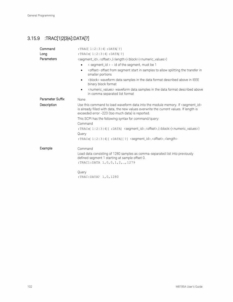
General Programming
102 M8195A User’s Guide
3.15.9 :TRAC[1|2|3|4]:DATA[?]
Command :TRAC[1|2|3|4]:DATA[?]
Long :TRACe[1|2|3|4]:DATA[?]
Parameters <segment_id>,<offset>,(<length>|<block>|<numeric_values>)
< segment_id > – id of the segment, must be 1
<offset> offset from segment start in samples to allow splitting the transfer in
smaller portions
<block> waveform data samples in the data format described above in IEEE
binary block format
<numeric_values> waveform data samples in the data format described above
in comma separated list format
Parameter Suffix None
Description Use this command to load waveform data into the module memory. If <segment_id>
is already filled with data, the new values overwrite the current values. If length is
exceeded error -223 (too much data) is reported.
This SCPI has the following syntax for command/query:
Command
:TRACe[1|2|3|4][:DATA] <segment_id>,<offset>,(<block>|<numeric_values>)
Query
:TRACe[1|2|3|4][:DATA][?] <segment_id>,<offset>,<length>
Example Command
Load data consisting of 1280 samples as comma-separated list into previously
defined segment 1 starting at sample offset 0.
:TRAC1:DATA 1,0,0,1,2,…,1279
Query
:TRAC:DATA? 1,0,1280

General Programming
M8195A User’s Guide 103
3.15.10 :TRAC[1|2|3|4]:IMP
Command :TRAC[1|2|3|4]:IMP
Long :TRACe[1|2|3|4]:IMPort
Parameters <segment_id>,<file_name>,TXT|BIN|BIN8|IQBIN|
BIN6030|BIN5110|MAT89600|DSA90000|CSV,IONLy|QONLy,ON|OFF|1|0,[,ALENgth|FI
LL|[,<init_valueI>[,<init_valueQ>[,<ignore_header_parameters>]]
File Format Import segment data from a file. Different file formats are supported. An already
existing segment can be filled, or a new segment can be created. This can be used to
import real waveform data as well as complex I/Q data.
<segment_id> must be 1
<file_name> the complete path of the file.
TXT|BIN|BIN8|IQBIN|BIN6030|BIN5110|MAT89600|DSA90000|CSV. (See File Type)
<data_type> IONLy|QONLy
<marker_flag> ON|OFF|1|0 (See Marker Flag)
<padding> ALENgth|FILL (See Padding)
<init_valueI> – optional initialization value. For non-I/Q format this is a DAC value.
For I/Q file format this is the I-part of an I/Q sample pair in binary format (int8).
Defaults to 0 if not specified.
<init_valueQ> – optional initialization value, only applicable for I/Q file formats. This
is the Q-part of an I/Q sample pair in binary format (int8). Defaults to 0 if not
specified.
<ignore_header_parameters> ON|OFF|1|0 (See Ignore Header Parameters)
The supported file formats can contain marker bits. These are not available in
revision 1.

General Programming
104 M8195A User’s Guide
File Type TXT
Compatibility: Keysight M8190A, Tek AWG 7000
One file contains waveform samples for one M8195A channel as normalized values (-
1.0 .. +1.0) and (optionally marker values) separated by ‘,’ or ‘;’ or ‘\t’. Not given
marker values are just set to 0. Space ‘ ‘ and ‘\t’ are ignored. Line end can be \r or
\r\n. The waveform samples can be imported to any of the four M8195A channels.
Example (US locale)
0.7,0,1
0.9,1
Example (German locale):
0,7;0;1
0,9;1
In German locale it is recommended (but not required) to use ‘;’ or ‘\t’ as separator.
But it must then be ensured that the double really has a decimal point (‘,’) or there is
some space inserted to ensure correct parsing:
0,7,0,1
0 ,0,1
BIN
Compatibility: Keysight M8190A.
One file contains waveform samples for one channel. The waveform samples can be
imported to any of the four M8195A channels. Samples consist of binary int16 values
(in little endian byte order).
15 14 13 12 11 10 9 8 7 6 5 4 3 2 1 0
DB13 DB12 DB11 DB10 DB9 DB8 DB7 DB6 DB5 DB4 DB3 DB2 DB1 DB0 SYNM SMPM
When imported the MSBs DB13 to DB6 are used as 8-bit sample values. All other
bits including marker bits SYNM and SMPM are ignored.
BIN8
BIN8 is the most memory efficient file format for the M8195A without digital markers.
As a result, the fastest file download can be achieved
One file contains waveform samples for one channel. The waveform samples can be
imported to any of the four M8195A channels. Samples consist of binary int8 values:
7 6 5 4 3 2 1 0
DB7 DB6 DB5 DB4 DB3 DB2 DB1 DB0
IQBIN
Compatibility: Keysight M8195A.
One file contains waveform samples for two M8190A channels plus optionally digital
marker information.
Channel mapping
I is mapped to channel 1
Q mapped to channel 2
Sample Marker 1 is ignored
Sample Marker 2 is ignored

General Programming
M8195A User’s Guide 105
BIN6030
Compatibility: Keysight N6030
Binary int16 values (in little endian byte order). The Keysight N6030 has
15 bits and uses the most significant digits, ignoring the LSB. While importing, the 8
LSBs are used as sample values, all other bits are ignored.
15 14 13 12 11 10 9 8 7 6 5 4 3 2 1 0
DB13 DB12 DB11 DB10 DB9 DB8 DB7 DB6 DB5 DB4 DB3 DB2 DB1 DB0 X X
BIN5110
Compatibility: Keysight 5110A
Binary int16 I/Q sample pairs (in little endian byte order). May contain full 16 bit
DAC values without the marker bits or 14 bit value plus two markers.
When importing 16 bit values without markers the marker flag should be set to ‘OFF’
so that 8 LSB are ignored.
For option –R14 there are two possibilities how to map I and Q to the M8195A
channels:
1 I mapped to channel 1. Q mapped to channel 2
2 I mapped to channel 3. Q mapped to channel 4
When importing 14 bit value with markers, the mapping is the following:
1 I mapped to channel 1.
2 Q mapped to channel 2.
3 Marker SMPM ignored.
Marker SYNM ignored.
15 14 13 12 11 10 9 8 7 6 5 4 3 2 1 0
I13 I12 I11 I10 I9 I8 I7 I6 I5 I4 I3 I2 I1 I0 X SMPM
Q13 Q12 Q11 Q10 Q9 Q8 Q7 Q6 Q5 Q4 Q3 Q2 Q1 Q0 X SYNM
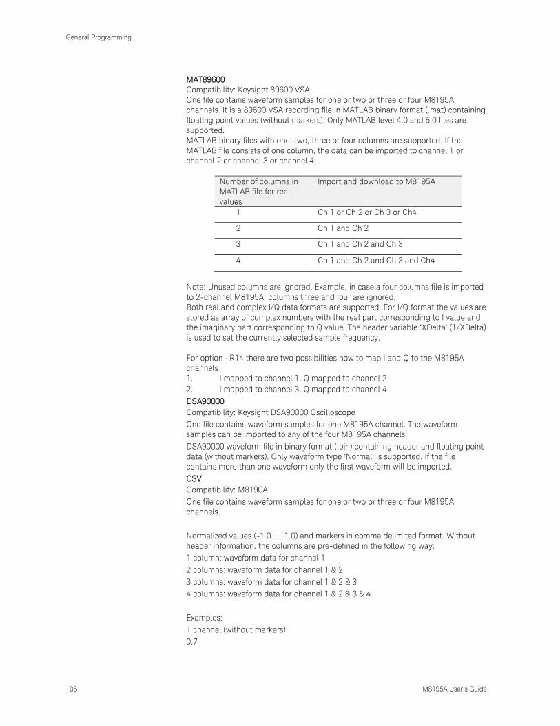
General Programming
106 M8195A User’s Guide
MAT89600
Compatibility: Keysight 89600 VSA
One file contains waveform samples for one or two or three or four M8195A
channels. It is a 89600 VSA recording file in MATLAB binary format (.mat) containing
floating point values (without markers). Only MATLAB level 4.0 and 5.0 files are
supported.
MATLAB binary files with one, two, three or four columns are supported. If the
MATLAB file consists of one column, the data can be imported to channel 1 or
channel 2 or channel 3 or channel 4.
Number of columns in
MATLAB file for real
values
Import and download to M8195A
1 Ch 1 or Ch 2 or Ch 3 or Ch4
2 Ch 1 and Ch 2
3 Ch 1 and Ch 2 and Ch 3
4 Ch 1 and Ch 2 and Ch 3 and Ch4
Note: Unused columns are ignored. Example, in case a four columns file is imported
to 2-channel M8195A, columns three and four are ignored.
Both real and complex I/Q data formats are supported. For I/Q format the values are
stored as array of complex numbers with the real part corresponding to I value and
the imaginary part corresponding to Q value. The header variable ‘XDelta’ (1/XDelta)
is used to set the currently selected sample frequency.
For option –R14 there are two possibilities how to map I and Q to the M8195A
channels
1. I mapped to channel 1. Q mapped to channel 2
2. I mapped to channel 3. Q mapped to channel 4
DSA90000
Compatibility: Keysight DSA90000 Oscilloscope
One file contains waveform samples for one M8195A channel. The waveform
samples can be imported to any of the four M8195A channels.
DSA90000 waveform file in binary format (.bin) containing header and floating point
data (without markers). Only waveform type ‘Normal’ is supported. If the file
contains more than one waveform only the first waveform will be imported.
CSV
Compatibility: M8190A
One file contains waveform samples for one or two or three or four M8195A
channels.
Normalized values (-1.0 .. +1.0) and markers in comma delimited format. Without
header information, the columns are pre-defined in the following way:
1 column: waveform data for channel 1
2 columns: waveform data for channel 1 & 2
3 columns: waveform data for channel 1 & 2 & 3
4 columns: waveform data for channel 1 & 2 & 3 & 4
Examples:
1 channel (without markers):
0.7

General Programming
M8195A User’s Guide 107
0.9
…
2 channel (without markers):
0.7,0.7
0.9,1.0
…
3 channels (without markers):
0.7,0,65,0.36
0.8,0,66,0.35
0.9,0,67,0.34
…
4 channels (without markers):
0.7,0,65,0.36,-0.1
0.8,0,66,0.35;-0.2
0.9,0,67,0.34;-0.33
…
The CSV format may contain optional header information as follows:
Parameter Header
The parameter header contains optional header parameters as name and value pairs
separated by ‘=’. Each parameter should be specified in a single line. This header is
optional. There are following header parameters:
SampleRate
The sample rate.
SetConfig
Flag to indicate if the header parameters need to be set. This can be set to either
‘true’ or ‘false’. If this flag is ‘false’ header parameters will not be set. If this flag is
omitted header parameters are set.
Data Header
The data header contains the names of the data columns separated by ','. The
waveform data are specified after the data header. This header is optional. If this
header is not specified the data need to be defined similar to CSV files without the
header (see above). The data columns are as follows:
Y1
Waveform data for channel 1.
Y2
Waveform data for channel 2.
Y3

General Programming
108 M8195A User’s Guide
Waveform data for channel 3.
Y4
Waveform data for channel 4.
SampleMarker1
Sample Marker for channel 1.
SampleMarker2
Sample Marker for channel 2.
Notes: If any of the marker columns (SampleMarker1 or Sample Marker2) is present
for a channel the data header must contain the waveform data column (Y1 or Y2). It
is possible to have only the data columns (Y1 , Y2, Y3, Y4 or any combination)
without the marker columns though.
Examples:
SampleRate = 7.2 GHz
Y1, Y2, SampleMarker1, SampleMarker2
0.7,0.7,0,0
0.9,1.0,0,1
0.3,-0,3,1,1
…
Y1, SampleMarker1
0.7,0
0.9,1
0.3,0
…
Y1, SampleMarker1, SampleMarker2
0.7,0,0
0.9,0,1
0.3,1,1
…
Y1, Y2, Y4
0.7,0,65,0.36
0.8,0,66,0.35
0.9,0,67,0.34
…
Marker Flag This flag is used to specify if the marker data need to be downloaded or not. If this
flag is ‘OFF’ marker data will not be downloaded. Default value is ‘ON’. This flag is
applicable to BIN5110 format only . If BIN5110 format consists of full 16 bit DAC
values (without markers) this flag should be set to ‘OFF’ so that 2 LSB’s are ignored.

General Programming
M8195A User’s Guide 109
Padding ALENgth: Automatic LENgth : <segment_id> may or may not exist. After execution
<segment_id> has exactly the length of the pattern in file or a multiple of this length
to fulfill granularity and minimum segment length requirements. Formula: length =
granularity * max(5 , # samples in file). This behavior is default if <padding> is
omitted.
FILL: <segment_id> must exist. If pattern in file is larger than the defined segment
length, just ignore excessive samples. If pattern in file is smaller than defined
segment length, fill remaining samples with <init_value>. <init_value> defaults to 0 if
it is not specified.
Ignore Header
Parameters Flag
This flag is used to specify if the header parameters need to be set. If this flag is ‘ON’
header parameters will not be set. This flag is optional and the default value is ‘OFF’
i.e. by default the header parameters are set . This flag is applicable to formats (CSV,
LICensed and MAT89600) that contain header parameters.
Example Command
:TRAC1:IMP 1, "C:\Program Files
(x86)\Keysight\M8195\Examples\WaveformDataFiles\
Sin10MHzAt64GHz.bin", BIN, IONLY, ON, ALEN

General Programming
110 M8195A User’s Guide
3.15.11 :TRAC[1|2|3|4]:DEL
Command :TRAC[1|2|3|4]:DEL
Long :TRACe[1|2|3|4]:DELete
Parameters <segment_id>– id of the segment, must be 1
Parameter Suffix None
Description Delete a segment. The command can only be used in program mode.
Example Command
:TRAC:DEL 1
3.15.12 :TRAC[1|2|3|4]:DEL:ALL
Command :TRAC[1|2|3|4]:DEL:ALL
Long :TRACe[1|2|3|4]:DELete:ALL
Parameters None
Parameter Suffix None
Description Delete all segments. The command can only be used in program mode.
Example Command
:TRAC:DEL:ALL
3.15.13 :TRAC[1|2|3|4]:CAT?
Command :TRAC[1|2|3|4]:CAT?
Long :TRACe[1|2|3|4]:CATalog?
Parameters None
Parameter Suffix None
Description The query returns a comma-separated list of segment-ids that are defined and the
length of each segment. So first number is a segment id, next length …
If no segment is defined, “0, 0” is returned.
Example Query
:TRAC1:CAT?
3.15.14 :TRAC[1|2|3|4]:FREE?
Command :TRAC[1|2|3|4]:FREE?
Long :TRACe[1|2|3|4]:FREE?
Parameters None
Parameter Suffix None
Description The query returns the amount of memory space available for waveform data in the
following form: <bytes available>, <bytes in use>, < contiguous bytes available>.
Example Query
:TRAC:FREE?

General Programming
M8195A User’s Guide 111
3.15.15 :TRAC[1|2|3|4]:NAME[?]
Command :TRAC[1|2|3|4]:NAME[?]
Long :TRACe[1|2|3|4]:NAME[?]
Parameters <segment_id>,<name>
Parameter Suffix None
Description This command associates a name to a segment. The query gets the name for a
segment.
<segment_id> – must be 1
<name> – string of at most 32 characters
Example Command
:TRAC:NAME 1,”ADY”
Query
:TRAC:NAME? 1

General Programming
112 M8195A User’s Guide
3.15.16 :TRAC[1|2|3|4]:COMM[?]
Command :TRAC[1|2|3|4]:COMM[?]
Long :TRACe[1|2|3|4]:COMMent[?]
Parameters <segment_id>,<comment>
Parameter Suffix None
Description This command associates a comment to a segment. The query gets the comment for
a segment.
<segment_id> – must be 1
<comment> – string of at most 256 characters
Example Command
:TRAC:COMM 1, “Comment”
Query
:TRAC:COMM? 1
General Programming
M8195A User’s Guide 113
3.16 :TEST Subsystem
3.16.1 :TEST:PON?
Command :TEST:PON?
Long :TEST:PON?
Parameters None
Parameter Suffix None
Description Return the results of the power on self-tests.
Example Query
:TEST:PON?
3.16.2 :TEST:TST?
Command :TEST:TST?
Long :TEST:TST?
Parameters None
Parameter Suffix None
Description Same as , but the actual test messages are returned.
Example Query
:TEST:TST?
Currently same as :TEST:PON?


Keysight M8195A – Arbitrary Waveform Generator
User’s Guide
Keysight M8195A User’s Guide
4 Examples
4.1 Introduction / 115
4.2 Remote Programming Examples / 115
4.3 Example Files for Import / 115
4.4 Example Correction Files / 115
4.5 Example Custom Modulation Files / 116
4.1 Introduction
In a standard installation the examples can be found in the folder “C:\Program Files
(x86)\Keysight\M8195\Examples”.
4.2 Remote Programming Examples
The MATLAB IQtools are described in file “README.docx” in subfolder
“MATLAB\iqtools”.The C++, C# and VB programs are provided as Visual Studio 2008
solutions. But they can be easily converted to more recent Visual Studio versions.
They show how to connect to the AWG, write a sine wave into the memory and start
signal generation. They use the VISA or VISA-COM libraries.
4.3 Example Files for Import
The subfolder “WaveformDataFiles” contains examples for all supported import file
formats. To import them use either the SFP Import Waveform panel or the SCPI
command TRAC[1|2|3|4]:IMP.
4.4 Example Correction Files
The subfolder “CorrectionFiles” contains examples to be used in the SFP
Multi-Tone and Complex Modulation panels.

Examples
116 M8195A User’s Guide
4.5 Example Custom Modulation Files
The subfolder “CustomModulationFiles” contains examples to be used in the SFP
Complex Modulation panel.

Keysight M8195A – Arbitrary Waveform Generator
User’s Guide
Keysight M8195A User’s Guide
5 Appendix
5.1 Resampling Algorithms for Waveform Import / 117
5.1 Resampling Algorithms for Waveform Import
5.1.1 Resampling Requirements
Resampling is typically associated to a series of processes applied to a waveform
sampled at a given sampling frequency to generate a new waveform with a different
sampling rate while preserving all the original information contained in the signal
within the Nyquist bandwidth corresponding to the output sampling rate. Processes
involved in resampling may vary depending on the output to input sampling rate ratio
(or resampling factor) and the integer nature of the ratio itself. Resampling
calculations, when applied to arbitrary waveform generation, must meet additional
constraints such as available record length boundaries, record length granularity
requirements, or acceptable sampling rate range.
Typically the characteristics of the input waveform (sampling rate, record length) are
externally defined (i.e. by the horizontal settings of an oscilloscope used to capture
the waveform). Users may be interested in resampling the signal to adapt the input
waveform to the AWG requirements or the user desires. In some cases it may be
necessary to reduce the sampling rate if it has been captured at a higher sampling
rate than the one allowed by the AWG or to reduce the record length required to
generate it. The opposite is also true as oversampling may help to “smooth” the
signal as increasing sampling rate will shift the images created by the DAC to a
higher frequency. Finally, resampling may be also necessary to adapt the record
length of the input waveform to a legal record length that can be applied to a real
AWG (i.e. to meet the record length granularities) without applying truncation or
“zero padding” to the input waveform.
Appendix
118 M8195A User’s Guide
5.1.2 Resampling Methodology
Generally speaking, resampling factors do not have to be an integer or a simple
fractional ratio. Because of that, traditional methods based in
upsampling/filtering/decimation techniques may not be suitable given the amount of
calculations resulting from the typical input waveform sizes involved. Instead of this,
a more straight forward approach has been chosen. This approach is based in the
following principles:
Only output samples will be calculated so there is not any up-sampling and/or
down-sampling operations involved.
Filtering calculations will be kept to a minimum by using a filter with a fast
enough roll-off and sufficient stop band attenuation according to the target
AWG dynamic range.
Interpolation filter and anti-alias filters are exactly the same although the filter
parameters will depend on the resampling parameters.
The implemented algorithm does perform filtering and interpolation
simultaneously so the number of calculations is greatly reduced. Additionally,
filters are implemented as look-up tables so those are calculated only once
during the process.
Timing parameters are based in double precision floating-point numbers while
amplitude related parameters are single precision numbers. Most calculations
consist in multiplication/addition operations required by convolution processes
and only involve amplitude related variables (input samples and filter
coefficients). Single precision numbers will minimize calculation time while
offering more than enough dynamic range.
Interpolators and anti-aliasing filters share most characteristics as they are required
to be low-pass with good flatness, linear phase, fast roll-off, and high stop-band
rejections ratio. Ideal interpolator filters show a “brick-wall” response. However, such
filters require a very long “sinc-like” impulse response to obtain good-enough
performance. Impulse response length has a direct effect on calculation times
resulting of applying the filter. Roll-off characteristics are especially important when
applying the filter as the anti-alias filter required for down-sampling. The filter
implemented in these algorithms has been designed with the following objectives:
Pass band flatness better than 0.01 dB
Stop band attenuation better than 80 dB
F80dB/F3dB ratio better than 1.15
The final filter consists in a sinc signal with a 41 sample periods length after applying
a Blackman-Harris time-domain window.

Appendix
M8195A User’s Guide
Figure 17: Interpolation/Antialiasing filter
The filter shape remains the same no matter the resampling characteristics. For
resampling ratios greater than 1.0, filter will implement an interpolator so nulls in the
impulse response must be located at multiples of the sampling period of the input
signal. For ratios lower than 1.0 the filter will implement an antialiasing filter. In this
case, distance between nulls will have to be longer than the output waveform
sampling period so the filter reach the required attenuation (>80dB) at the output
signal Nyquist frequency. For the implemented filter this is accomplished by
choosing 0.89 ratio between the output sampling period and the distance between
consecutive nulls in the filter’s impulse response.

This information is subject to change without notice.
© Keysight Technologies 2014
Edition 2.0, October 2014
www.keysight.com